st80caps: replacing the large capacitors in a … amp is surprisingly heavy…don’t drop ......
TRANSCRIPT
Page 1 of 15
ST80CAPS: Replacing the Large
Capacitors in a Stereo 80
© 2016 AkitikA, LLC All rights reserved
Revision 1p2 March 27, 2016

Page 2 of 15
Table of Contents Table of Contents................................................................................................................ 2 Table of Figures .................................................................................................................. 2 Section 1: About This Manual ............................................................................................ 3
Who Should Attempt these Projects? ............................................................................. 3 Tools You’ll Need........................................................................................................... 3 Project Overview ............................................................................................................ 3
Section 2: Some Background Information.......................................................................... 4 What symptoms might say I need new capacitors? .................................................... 4 What are the benefits of larger capacitors?................................................................. 4
Section 3: Replacing the Capacitors ................................................................................... 5 Getting Started ................................................................................................................ 5 Replacing C11................................................................................................................. 5 Replacing C9................................................................................................................... 6
Removing C9 .............................................................................................................. 6 Building the Dynamite Capacitor ............................................................................... 6
Installing the New C9 into the Amplifier ....................................................................... 8 Replacing C7 (Two Places) .......................................................................................... 10
Removing Left and Right Channel C7’s................................................................... 10 Building the Dynamite Capacitors............................................................................ 11
New C7 Capacitors Mechanical Installation................................................................. 14 Left Channel C7........................................................................................................ 14 Right Channel C7...................................................................................................... 14
Test and Final Assembly............................................................................................... 14 References..................................................................................................................... 15
Table of Figures Figure 1-Locating the capacitors ........................................................................................ 5 Figure 2-Note the position of the caps, offset from the mounting feet............................... 7 Figure 3-Ground Harness Configuration ............................................................................ 7 Figure 4-Soldering the ground positive harnesses on the new C9 dynamite capacitor arrangement......................................................................................................................... 8 Figure 5-Note the orientation of the capacitor assembly when installed into the amplifier9 Figure 6-Detail for C7....................................................................................................... 10 Figure 7-3 25 mm diameter capacitors take the space of one 2" diameter capacitor ....... 11 Figure 8-A bit of squeezing as indicated triangularizes the bracket, making it easy to tighten the clamp screw (the wires shown in the picture are added in a later step).......... 12 Figure 9-Negative Terminal Configuration ...................................................................... 12 Figure 10-Inductor wound around the new C7 ................................................................. 13 Figure 11-Adding red wires to connect positive terminals............................................... 13

Page 3 of 15
Section 1: About This Manual This manual gives the directions you’ll need to install the ST80CAPS kit into a Dynaco Stereo 80 Power Amplifier. This kit replaces and upgrades the original chassis mounted electrolytic capacitors with new, larger capacitors. This results in more power and better bass, making your Stereo 80 better than new. The ST80CAPS kit collects a number of other Updatemydynaco kits into one. It includes:
Half of a PSRC - a single 3900 µF 100 Volt capacitor which replaces C11, which was a 1000 µF capacitor. This increase also decreases noise and distortion by better filtering the driver supply rail.
C7X2 kit - a dynamite capacitor arrangement that bumps the output capacitor value from 5000 µF to 9900 µF, improving bass power and lowering bass distortion. A single C7X2 kit replaces both the left and right C7 output capacitors. The C7X2 kit also includes a 100K resistor that isn’t used in the Stereo 80 application.
SCA80C9 kit - replaces the original 5000 µF C9 bulk filter with 9900 µF in a dynamite capacitor arrangement. Once again, this increase in capacitance lowers distortion and allows the ST80 to produce more power, and in particular, more power at low frequencies.
Who Should Attempt these Projects? You can build this kit if you can:
1. solder (using normal rosin core solder and a soldering iron). 2. use simple hand tools like screwdrivers, wire cutters, and pliers. 3. read and follow directions.
It helps if you: 1. know a bit about electronics, or 2. have a friend who knows a bit about electronics 3. can get to YouTube to watch a few helpful videos about the assembly process (not
available as of this version of the manual)
Tools You’ll Need You’ll need the following tools:
1. flat blade screwdriver for #6 screws 2. needle nose pliers (helpful, but not strictly necessary) 3. pencil type soldering iron of 25 to 50 Watts (no huge honking soldering guns or
blowtorches) 4. wire cutters and strippers 5. Magnifying glass, if you’re over 42!
Project Overview The project consists of the following steps:
1. Removing the old capacitors. 2. Building and installing the new capacitors
Page 4 of 15
By purchasing, using, or assembling this kit, you have agreed to hold AkitikA, LLC harmless for any injuries you may receive in its assembly and/or use. To prevent injuries:
Wear safety glasses when soldering to prevent eye injuries. Always unplug the power before working on the amplifier. Large capacitors hold lots of energy for a long time. Before you put your hands
into the amplifier: o Pull the AC plug! o Wait 1 full minute for the capacitors to discharge!
Remove jewelry and rings from your hands and wrists, or anything that might dangle into the amplifier.
If working in the amplifier, keep one hand in your pocket, especially if you’re near the power supply or power supply wires. This can prevent serious shocks.
Build with a buddy nearby. If you’ve ignored all the previous advice, they can dial 911 or get you to the hospital.
Section 2: Some Background Information
What symptoms might say I need new capacitors? Do both channels hum? Hum is often caused by a reduction in the value of C11 and C9. This happens as the capacitors age. Heat quickens the deterioration of the capacitors, so if your Stereo 80 was used or stored in a warm place, it’s quite likely that your capacitors have lost capacitance. Is one (or both) channels dead? While there are many ways that a channel can “die”, one fairly benevolent failure mode is when the speaker coupling caps open up. This is a fairly common failure mechanism. Of course, there may be other causes of a dead channel, so replacing C7 is no guarantee of a cure.
What are the benefits of larger capacitors? The amplifiers run on direct current (DC). The power delivered to your house is alternating current (AC). The bridge rectifier and filter capacitors change AC into DC. The larger the capacitors, the steadier and quieter is the resulting DC that powers the amplifiers. This lets the amplifier circuits deliver the most power and least distortion. The speaker coupling capacitors couple the amplifier’s output to the speakers. Larger capacitors here mean that more power can be delivered at low frequencies with less distortion.

Page 5 of 15
Section 3: Replacing the Capacitors
Figure 1-Locating the capacitors
Getting Started Please work safely. There are lethal voltages inside the Stereo 80. Following these directions will greatly reduce your chances of injury.
1. Pull the plug out of the wall socket. 2. Don’t open the amp until one full minute after the plug has been pulled. 3. The amp is surprisingly heavy…Don’t drop it!
Replacing C11 1. Mark the 3 wires that connect to the positive terminal of C11. The original caps
marked the positive terminal with a bit of red paint on the terminal. Masking tape and a magic market is a handy way to make labels for these wires.
2. Desolder the wires that connect to the positive terminal of C11. 3. Mark the wire that connects to the negative terminal of C11. The original caps
marked the negative terminal with a bit of black paint on the terminal. Masking tape and a magic marker is a handy way to label this wire.
4. Loosen the clamp that holds C11 in place. If that screw/nut isn’t accessible, you may have to remove the screws that hold the clamp to the chassis. Wiggle C11 out of the clamp.

Page 6 of 15
5. Take the 3900 µF 100 Volt capacitor from the ST80CAPS kit. It may be in an envelope marked as “Half of a PSRC”.
6. Install the new cap into the C11 clamp and snug up the clamp-band screw. There is some variation in the diameter of the new cap, compared to the old one. You may find that it’s helpful to wind a few turns of electrical tape around the bottom of the new capacitor to build-out its diameter to comfortably fit the old clamp.
7. Make sure that the positive terminal of the new capacitor (the one without the minus sign) is placed closest to the circuit boards.
8. Crimp and solder the three positive terminal marked wires to the positive terminal.
9. Crimp and solder the one negative terminal marked wire to the negative terminal of the capacitor (marked by the negative signs on the side of the capacitor).
Please double check the polarity. A capacitor installed backwards can explode.
Replacing C9 The raw materials for building the new C9 are found in the kit labeled “SCA80C9”. These will be 3300 µF caps rated at 80 volts (or more).
Removing C9 1. Tag the wires connected to C9 with plus and minus labels before desoldering
them from C9’s terminals. 2. Remove the three sets of 6-32 hardware (screw, nut, and lock-washer) that hold
C9 to the chassis. 3. Lift C9 and its retaining clamp out of the chassis.
Building the Dynamite Capacitor 1. You’ll replace C9, a single 2” diameter capacitor with three 25 mm diameter
capacitors, as shown in Figure 2. 2. Orient the three capacitors with the negative leads in the center of the grouping. 3. Position the group of three caps as shown in Figure 2. That positioning allows you
to slightly bend the clamp to allow all three mounting holes to match the chassis. 4. Use the supplied 6-32x5/8” Phillips head sem screw (built-in lockwasher) and
keps nut (also with a built in lockwasher) to tighten the clamp once the caps are correctly located.
5. For now, tighten the screws a bit more than finger-tight. 6. Turn the amp over, and locate the chassis mounting holes for C9. Match these
holes with the holes in the C9 mounting clamp. All three holes might match straight away. However, you may find that a little creative clamp bending is needed to get you a pretty good match on all three holes.
7. Snug up the mounting clamp hardware, but don’t go too tight. Re-check for a 3-hole match. If you can only get a two hole-match, don’t worry...that will retain the caps just fine.

Page 7 of 15
Figure 2-Note the position of the caps, offset from the mounting feet
8. Construct the ground harness for the caps: a. Remove 4” of insulation from the supplied 20 AWG wire. b. Cut the resulting bare wire into two 2” long pieces. c. Twist and shape the wires as shown in Figure 3.
Figure 3-Ground Harness Configuration
9. Solder the center section as indicated. Place the soldered portion of the jumper in the center of the dynamite capacitor configuration. Hook the ends of three of the four wires to the three negative terminals of the capacitors. Solder the wires to the negative terminals.
10. Form the remaining wire upward, away from the caps. You’ll attach it to the amplifier ground connection in a later step.
11. Prepare the Positive Wire Harness as follows (see Figure 4): a. Cut two pieces of red 20 AWG wire, each to a length of 2”.
Page 8 of 15
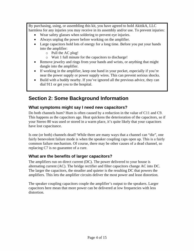
b. Remove ¼” of insulation from the ends of the wires (4 places). c. Form the bare ends into hooks. Crimp the hooks around the positive
terminals of the capacitor as shown in Figure 4. Solder the connections, making sure to leave room for additional wires added in later step
Figure 4-Soldering the ground and positive harnesses on the new C9 dynamite capacitor
arrangement
Installing the New C9 into the Amplifier 1. Install the clamp, capacitor, harness assembly into the amplifier. Use the keps
nuts with the built in lockwashers (the 3 old nuts and lockwashers aren’t used). 2. Orient and wire the new assembly as shown in Figure 5. 3. Inspect your work carefully. Make sure that there is no possible way for wires
connected to the positive and negative terminals of the new C9 configuration to come into contact.

Page 9 of 15
Figure 5-Note the orientation of the capacitor assembly when installed into the amplifier
Page 10 of 15
Replacing C7 (Two Places)
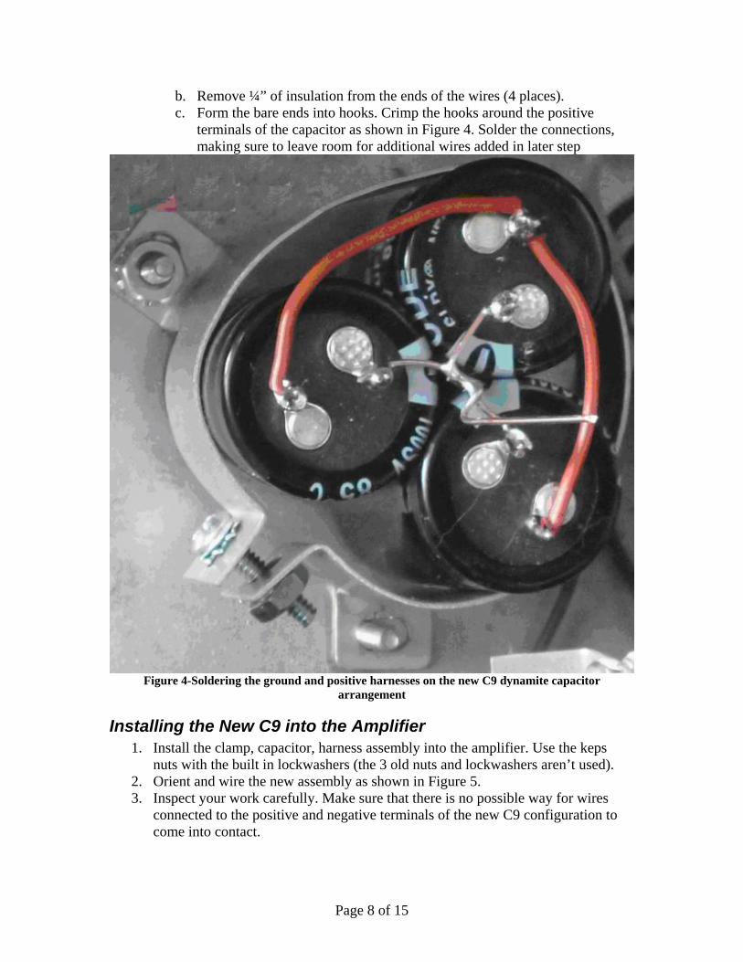
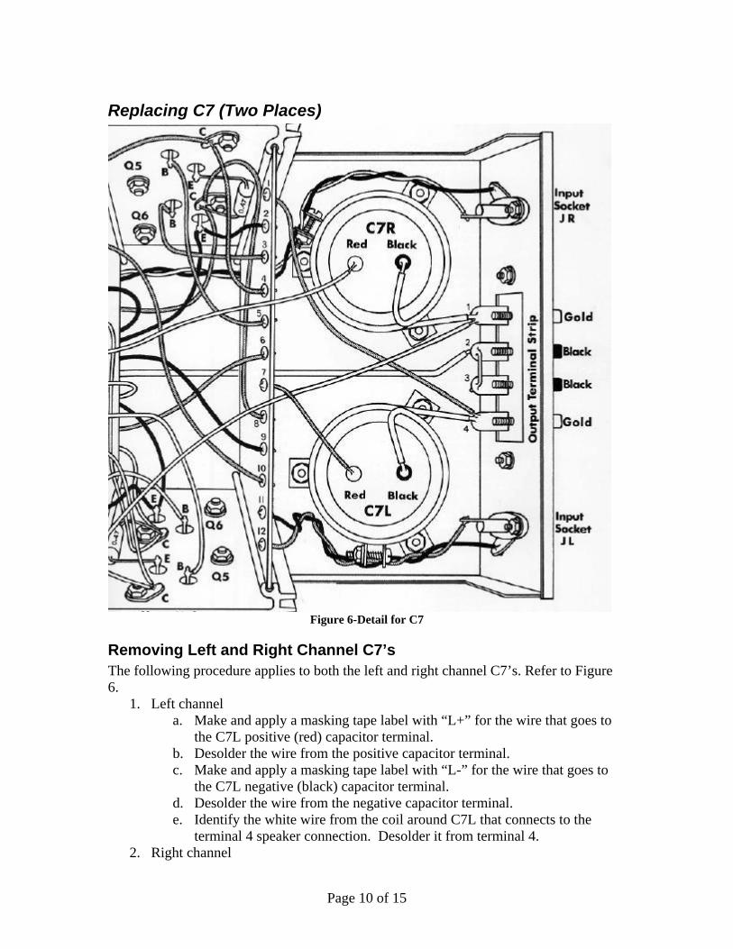
Figure 6-Detail for C7
Removing Left and Right Channel C7’s The following procedure applies to both the left and right channel C7’s. Refer to Figure 6.
1. Left channel a. Make and apply a masking tape label with “L+” for the wire that goes to
the C7L positive (red) capacitor terminal. b. Desolder the wire from the positive capacitor terminal. c. Make and apply a masking tape label with “L-” for the wire that goes to
the C7L negative (black) capacitor terminal. d. Desolder the wire from the negative capacitor terminal. e. Identify the white wire from the coil around C7L that connects to the
terminal 4 speaker connection. Desolder it from terminal 4. 2. Right channel

Page 11 of 15
a. Make and apply a masking tape label with “R+” for the wire that goes to the C7R positive (red) capacitor terminal.
b. Desolder the wire from the positive capacitor terminal. c. Make and apply a masking tape label with “R-” for the wire that goes to
the C7R negative (black) capacitor terminal. d. Desolder the wire from the negative capacitor terminal. e. Identify the white wire from the coil around C7R that connects to the
terminal 1 speaker connection. Desolder it from terminal 1. 3. Remove the three screws that hold the capacitor clamp to the chassis. Save the
screws for re-assembly. The kit provides 6 keps nuts (nuts with attached lockwashers) to make reassembly easier. Don’t loosen the capacitor clamp screw yet.
4. Sit the old capacitor in its clamp on a piece of paper, and trace the mounting hole locations on the piece of paper. You’ll use this template to guide a bit of creative bending in an upcoming step. Repeat this step for the other old C7.
Building the Dynamite Capacitors The actions described in this section must be performed twice, once for the left channel, and then again for the right channel.
1. You’ll replace C7, a single 2” diameter capacitor with three 25 mm diameter capacitors, as shown in Figure 7.
2. Loosen the capacitor clamp screw and remove the original C7.
Figure 7-3 25 mm diameter capacitors take the space of one 2" diameter capacitor
3. Orient the three capacitors with the negative leads in the center of the grouping. a. The space between two capacitors should be located next to the clamp
tightening screw. b. Place the group of three capacitors in the clamp as shown in Figure 8.
Referring to Figure 8, squeeze and bend the clamp a little by pushing inward toward the spaces between the capacitors in the triangle capacitor pattern. This makes it easy to use the supplied 6-3/8x5/8” screw in the capacitor clamp. (Note that the capacitors won’t be wired at this point of the assembly).

Page 12 of 15
c. Tighten the capacitor clamp screw until the holes in the clamp align with the holes recorded on your template. This will make it easy to install the upgraded C7 capacitor assembly in later steps.
4. Remove and straighten the white wire that was wrapped around the old C7. It will be reused (though not all of it) to create the new inductor for the new C7.
5. Strip a bit more than 2” of insulation from the white wire. Clean the bare wire by lightly scraping it with the jaws of the diagonal cutters or by cleaning it with isopropyl alcohol. This step is not strictly necessary, but it may make the wire a bit easier to solder.
Figure 8-A bit of squeezing as indicated triangularizes the bracket, making it easy to tighten the clamp screw (the wires shown in the picture are added in a later step).
6. Form the bare wire as shown to connect together all three negative terminals as shown in Figure 9. Solder the terminals.
Figure 9-Negative Terminal Configuration
Page 13 of 15
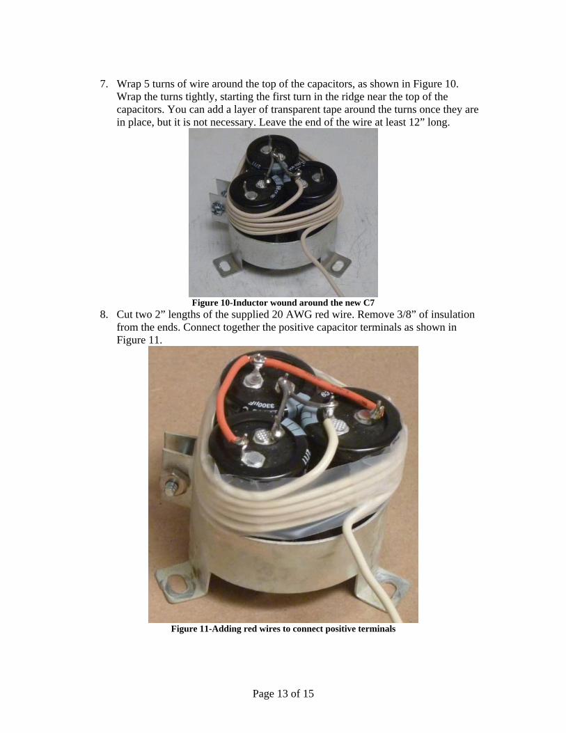
7. Wrap 5 turns of wire around the top of the capacitors, as shown in Figure 10.
Wrap the turns tightly, starting the first turn in the ridge near the top of the capacitors. You can add a layer of transparent tape around the turns once they are in place, but it is not necessary. Leave the end of the wire at least 12” long.
Figure 10-Inductor wound around the new C7
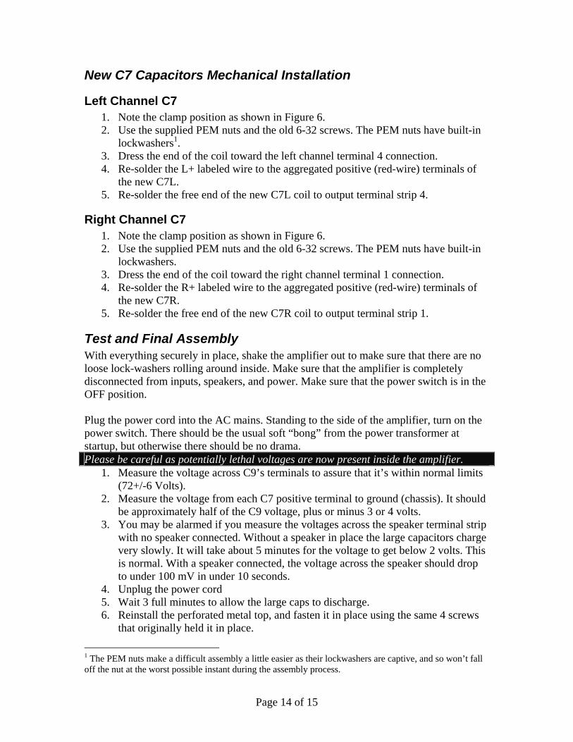
8. Cut two 2” lengths of the supplied 20 AWG red wire. Remove 3/8” of insulation from the ends. Connect together the positive capacitor terminals as shown in Figure 11.
Figure 11-Adding red wires to connect positive terminals
Page 14 of 15
New C7 Capacitors Mechanical Installation
Left Channel C7 1. Note the clamp position as shown in Figure 6. 2. Use the supplied PEM nuts and the old 6-32 screws. The PEM nuts have built-in
lockwashers1. 3. Dress the end of the coil toward the left channel terminal 4 connection. 4. Re-solder the L+ labeled wire to the aggregated positive (red-wire) terminals of
the new C7L. 5. Re-solder the free end of the new C7L coil to output terminal strip 4.
Right Channel C7 1. Note the clamp position as shown in Figure 6. 2. Use the supplied PEM nuts and the old 6-32 screws. The PEM nuts have built-in
lockwashers. 3. Dress the end of the coil toward the right channel terminal 1 connection. 4. Re-solder the R+ labeled wire to the aggregated positive (red-wire) terminals of
the new C7R. 5. Re-solder the free end of the new C7R coil to output terminal strip 1.
Test and Final Assembly With everything securely in place, shake the amplifier out to make sure that there are no loose lock-washers rolling around inside. Make sure that the amplifier is completely disconnected from inputs, speakers, and power. Make sure that the power switch is in the OFF position. Plug the power cord into the AC mains. Standing to the side of the amplifier, turn on the power switch. There should be the usual soft “bong” from the power transformer at startup, but otherwise there should be no drama. Please be careful as potentially lethal voltages are now present inside the amplifier.
1. Measure the voltage across C9’s terminals to assure that it’s within normal limits (72+/-6 Volts).
2. Measure the voltage from each C7 positive terminal to ground (chassis). It should be approximately half of the C9 voltage, plus or minus 3 or 4 volts.
3. You may be alarmed if you measure the voltages across the speaker terminal strip with no speaker connected. Without a speaker in place the large capacitors charge very slowly. It will take about 5 minutes for the voltage to get below 2 volts. This is normal. With a speaker connected, the voltage across the speaker should drop to under 100 mV in under 10 seconds.
4. Unplug the power cord 5. Wait 3 full minutes to allow the large caps to discharge. 6. Reinstall the perforated metal top, and fasten it in place using the same 4 screws
that originally held it in place.
1 The PEM nuts make a difficult assembly a little easier as their lockwashers are captive, and so won’t fall off the nut at the worst possible instant during the assembly process.

Page 15 of 15
You are ready to listen to music with better bass, higher signal to noise ratio, and lower distortion.
References Be sure to visit www.updatemydynaco.com to see the latest ways to make your Dynaco Solid State equipment better than new, or to download the latest version of this manual. Make sure that the 0.1 µF capacitors remain attached to the red speaker binding posts!