st tank-mounted suction filter - farnell element14 skb housings mta mtb gt zt rt rtd rti kft lrt bft...
TRANSCRIPT

FluidCompatibility
Type Fluid Appropriate Schroeder MediaPetroleum Based Fluids All Paper (E) and Synthetic (Z) media
High Water Content Z10Invert Emulsions Z10
Water Glycols Z10Phosphate Esters KZ10H, K10H
Skydrol KZ10H.5 Note: Contact factory regarding use of E Media in High Water Content, Invert Emulsion and Water Glycol Applications.
For more information, refer toFluid Compatibility:Fire Resistant Fluids,pages 19 and 20.
SCHROEDER INDUSTRIES98
Absolute Rating Per ISO 4572/NFPA T3.10.8.8 Abs. Rating wrt ISO 16889 Using automated particle counter (APC) calibrated per ISO 4402 Using APC calibrated per ISO 11171 Dirt Holding
Element ßx ≥ 75 ßx ≥ 100 ßx ≥ 200 ßx(c) ≥ 200 ßx(c) ≥ 1000 Capacity gm
K10 15.5 16.2 18.0 N/A N/A 44
KTZ10 7.4 8.0 10.0 10.0 12.7 56
Element Collapse Rating: 150 psid (10 bar)Flow Direction: Inside Out
Element Nominal Dimensions: 4.0” (100 mm) O.D. x 9.0” (230 mm) long
Flow Rating: Up to 20 gpm (75 L/min) for 150 SUS (32 cSt) fluids
Max. Operating Pressure: Suction Filter
Min. Yield Pressure: Not Applicable
Rated Fatigue Pressure: Not Applicable
Temp. Range: -20°F to 225°F (-29°C to 107°C)
Bypass Setting: Non-bypassing
Porting Head: Die Cast AluminumCap: Steel
Element Case: Steel
Weight of ST-1K: 11.1 lbs. (5.0 kg)Weight of ST-2K: 14.7 lbs. (6.7 kg)
Element Change Clearance: 7.25” (185 mm)
Filter Housing
Specifications
20 gpm75 L/min
Tank-Mounted Suction Filter
ElementPerformanceInformation
ST
6.25 MAX.
1.88(48)
(66)
1K =
8.8
1 (2
24)
2.59
5.06 (129) ØHOLE IN TANK
(162)
IN
OUT
6.38 PORT TO PORT
4.06 MAX.(103)
.44 (11) Ø ON A 6.25 (159) Ø B.C.
FOR INSTALLATION
GASKET.12 (3) THICK
2K =
18.
00 (
457)
OUT
7.00 Ø(178)
TYP45°
(159)
OPTIONAL DIRT ALARMOR ELECTRIC SWITCH
4.50(114)
Ø
OPTIONALCHECK VALVE
(4) MOUNTING HOLES
.88(22)
Metric dimensions in ( ).Model No. of filter in photograph is ST1K10SY.
Optional mounting ring availableto weld to tank.
ST
SKB Housings
MTA
MTB
GT
ZT
RT
RTD
RTI
KFT
LRT
BFT
Accessories for Tank-Mounted
Filters
Air Breathers
Filler StrainerAssemblies
Magnetic SuctionSeparators
Suction Strainers
PAF1
MAF1
MF2
TF1
TF3
KF3
WKF3
LF1
LF1—2"
MLF1
SRLT
SRLT
TRLT
RLT
RLT
WRLT
KF8
QF5
MQF5
QFD2
4QFD2
Filtration Carts
STAND-ALONE DISPOSABLE ELEMENT
™™
STAND-ALONE DISPOSABLE ELEMENT
™™
99SCHROEDER INDUSTRIES
FilterModelNumberSelection
OtherAvailableOptions
See Appendix B foradditional informationon these options andinstructions on how to order.
PressureDropInformationBased on Flow Rateand Viscosity
ElementSelectionBased on Flow Rate
Features
STTank-Mounted Suction Filter
Dirt AlarmFilter No. of Element Seal Outlet Optional (See Appendix A forSeries Elements Part No. Material Porting Check Valve complete list of options)
K10K25**
KTZ10
1ST
2
(Omit) = Buna N
H = EPR*
W = Buna N*
(Omit) = None
C = CheckValve
P = 11⁄2” NPTF
PP = Dual 11⁄2” NPTF
S = 17⁄8”-12 SAEStraight(SAE-24)
SS = Dual 17⁄8”-12SAE Straight(SAE-24)
B = ISO 228 G-11⁄2”(11⁄2-11 BSPP)
BB = Dual ISO 228G-11⁄2”(11⁄2-11 BSPP)
G501 = Rubber gasket G547 = Two 1⁄8” gauge ports
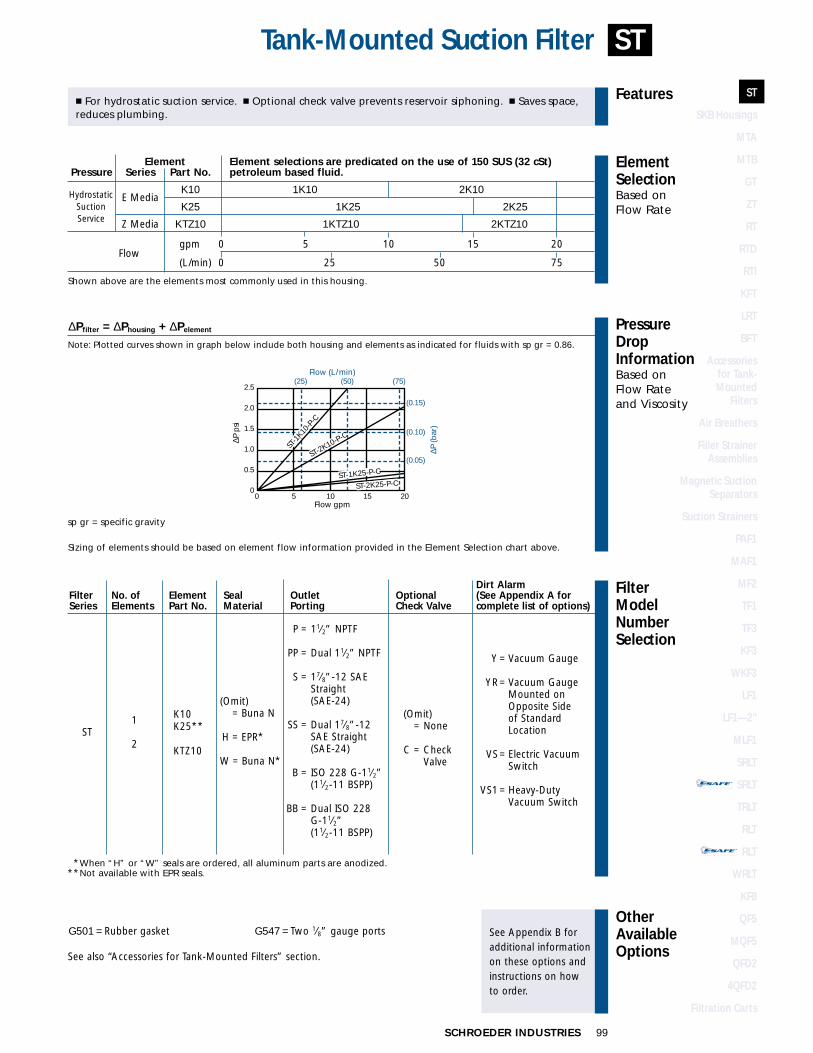
Element Element selections are predicated on the use of 150 SUS (32 cSt) Pressure Series Part No. petroleum based fluid.
K10 1K10 2K10E Media
K25 1K25 2K25
Z Media KTZ10 1KTZ10 2KTZ10
Flow gpm 0 5 10 15 20
(L/min) 0 25 50 75
Shown above are the elements most commonly used in this housing.
� For hydrostatic suction service. � Optional check valve prevents reservoir siphoning. � Saves space,reduces plumbing.
HydrostaticSuctionService
∆Pfilter = ∆Phousing + ∆Pelement
Note: Plotted curves shown in graph below include both housing and elements as indicated for fluids with sp gr = 0.86.
Sizing of elements should be based on element flow information provided in the Element Selection chart above.
sp gr = specific gravity
(25) (50) (75)2.5
2.0
1.5
1.0
0.5
0
(0.15)
(0.10)
(0.05)
0 5 10 15 20Flow gpm
Flow (L/min)
∆P (b
ar)
∆P p
si
ST-1
K10-P
-C
ST-2K10-P-C
ST-1K25-P-C
ST-2K25-P-C
Y = Vacuum Gauge
YR = Vacuum GaugeMounted onOpposite Sideof StandardLocation
VS = Electric Vacuum Switch
VS1 = Heavy-Duty Vacuum Switch
**When “H” or “W” seals are ordered, all aluminum parts are anodized.**Not available with EPR seals.
See also “Accessories for Tank-Mounted Filters” section.
SCHROEDER INDUSTRIES100
In-Line Magnetic Suction Separators
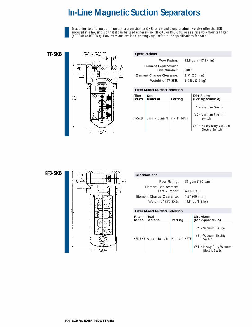
TF-SKB
KF3-SKB
Filter Seal Dirt AlarmSeries Material Porting (See Appendix A)
KF3-SKB Omit = Buna N P = 11⁄2” NPTF
Y = Vacuum Gauge
VS = Vacuum ElectricSwitch
VS1 = Heavy Duty VacuumElectric Switch
Specifications
Flow Rating: 35 gpm (130 L/min)
Element ReplacementPart Number: A-LF-1789
Element Change Clearance: 1.5” (40 mm)
Weight of KF3-SKB: 11.5 lbs (5.2 kg)
Filter Seal Dirt AlarmSeries Material Porting (See Appendix A)
TF-SKB Omit = Buna N P = 1” NPTF
Y = Vacuum Gauge
VS = Vacuum ElectricSwitch
VS1 = Heavy Duty VacuumElectric Switch
Specifications
Flow Rating: 12.5 gpm (47 L/min)
Element ReplacementPart Number: SKB-1
Element Change Clearance: 2.5” (65 mm)
Weight of TF-SKB: 5.8 lbs (2.6 kg)
Filter Model Number Selection
Filter Model Number Selection
In addition to offering our magnetic suction strainer (SKB) as a stand alone product, we also offer the SKBenclosed in a housing, so that it can be used either in-line (TF-SKB or KF3-SKB) or as a reservoir-mounted filter(KST-SKB or BFT-SKB). Flow rates and available porting vary—refer to the specifications for each.

ST
SKB Housings
MTA
MTB
GT
ZT
RT
RTD
RTI
KFT
LRT
BFT
Accessories for Tank-Mounted
Filters
Air Breathers
Filler StrainerAssemblies
Magnetic SuctionSeparators
Suction Strainers
PAF1
MAF1
MF2
TF1
TF3
KF3
WKF3
LF1
LF1—2"
MLF1
SRLT
SRLT
TRLT
RLT
RLT
WRLT
KF8
QF5
MQF5
QFD2
4QFD2
Filtration Carts
STAND-ALONE DISPOSABLE ELEMENT
™™
STAND-ALONE DISPOSABLE ELEMENT
™™
STAND-ALONE DISPOSABLE ELEMENT
™™
STAND-ALONE DISPOSABLE ELEMENT
™™
101SCHROEDER INDUSTRIES
Tank-Mounted Magnetic Suction Separators
BFT-SKB
KST-SKB
1.78
(4
5)
Filter SealSeries Material Porting
P24P24 = 11⁄2” NPT
KST-SKB Omit = Buna N P24P24 = Dual11⁄2” NPT
Y = Vacuum GaugeYR = Y mounted on opposite sideVS = Vacuum Electric Switch
VSR = VS mounted on opposite sideVS1 = Heavy Duty Vacuum Electric Switch
Dirt Alarm Other(See Appendix A) Options
C = CheckValve
Specifications
Flow Rating: 35 gpm (130 L/min)
Element Replacement � with check valve: A-SKB-11P-1Part Number: � with check valve for filter built
before Sept. 95: A-SKB-131� without check valve: A-SKB-99� without check valve for filter
built before Sept. 95: A-SKB-130
Element Change Clearance: 9.0” (230 mm)
Weight of KST-SKB: 11.5 lbs (5.2 kg)
Filter SealSeries Material Porting
PP = 21⁄2” NPTFPP = Dual 21⁄2” NPTF
BFT-SKB Omit = FF = 21⁄2” SAE J518 4-Bolt Flange Code 61Buna N
FF = Dual 21⁄2” SAE J518 4-Bolt Flange Code 61
Dirt Alarm Other(See Appendix A) Options
Y = Vacuum GaugeYR = Y mounted on opposite sideVS = Vacuum Electric Switch
VSR = VS mounted on opposite sideVS1 = Heavy Duty Vacuum Electric Switch
C = CheckValve
Specifications
Flow Rating: 75 gpm (285 L/min)
Element Replacement with check valve: A-SKB-3-76Part Number: without check valve: SKB-3
Element Change Clearance: 13.5” (345 mm)
Weight of BFT-SKB: 32.0 lbs (14.5 kg)
Filter Model Number Selection
Filter Model Number Selection

SCHROEDER INDUSTRIES102
FluidCompatibility
Type Fluid Appropriate Schroeder MediaPetroleum Based Fluids All Paper (E) and Synthetic (Z) media For more
information, refer toFluid Compatibility:Fire Resistant Fluids,pages 19 and 20.
Absolute Rating Per ISO 4572/NFPA T3.10.8.8 Abs. Rating wrt ISO 16889 Using automated particle counter (APC) calibrated per ISO 4402 Using APC calibrated per ISO 11171 Dirt Holding
Element ßx ≥ 75 ßx ≥ 100 ßx ≥ 200 ßx(c) ≥ 200 ßx(c) ≥ 1000 Capacity gm
3TA10 15.5 16.2 18.0 N/A N/A N/A
3TAZ3 <1.0 <1.0 <2.0 4.7 5.8 4
3TAZ5 2.5 3.0 4.0 6.5 7.5 4
3TAZ10 7.4 8.2 10.0 10.0 12.7 4
3TAZ25 18.0 20.0 22.5 19.0 24.0 4
Element Collapse Rating: 150 psid (10 bar)Flow Direction: Outside In
Element Nominal Dimensions: 2.0” (51 mm) O.D. x 3.0” (76 mm) long
Flow Rating: Up to 15 gpm (55 L/min) for 150 SUS (32 cSt) fluids
Max. Operating Pressure: 100 psi (7 bar)
Min. Yield Pressure: 269 psi (18 bar)
Rated Fatigue Pressure: Contact factory
Temp. Range: -20°F to 225°F (-29°C to 107°C)
Bypass Setting: Cracking: 25 psi (2 bar)Full Flow: 48 psi (3.3 bar)
Porting Head & Cap: Die Cast AluminumElement Case: Glass Filled Nylon
Weight of MTA-3: 1.0 lbs. (0.5 kg)
Element Change Clearance: 3.0” (76 mm)
Filter Housing
Specifications
15 gpm55 L/min
100 psi7 bar
MiniMiser Tank-Mounted Filter
ElementPerformanceInformation
MTA
Metric dimensions in ( ).Model No. of filter in photograph is MTA3TAZ10P8.
2.00(51)
3.30 (109) 60°
.28 (7) Ø ON A 3.50 (89) Ø B.C.(2) MOUNTING
HOLES
Ø
1.84(47)
.89 (23)
.94 Ø(24)
2.69 (68) Ø HOLE IN TANK REQ'D FORINSTALLATION
2.37 Ø
(60)
IN
O-RING
BOWL
CAP
SPRING
O-RING
ELEMENT
BYPASS VALVE
O-RING
OPTIONAL MAGNET
5.06
(1
29)
3.22
(82)
OUT
OPTIONAL DIRT ALARMOR ELECTRIC SWITCH
2.19 MAX(56)
ST
SKB Housings
MTA
MTB
GT
ZT
RT
RTD
RTI
KFT
LRT
BFT
Accessories for Tank-Mounted
Filters
Air Breathers
Filler StrainerAssemblies
Magnetic SuctionSeparators
Suction Strainers
PAF1
MAF1
MF2
TF1
TF3
KF3
WKF3
LF1
LF1—2"
MLF1
SRLT
SRLT
TRLT
RLT
RLT
WRLT
KF8
QF5
MQF5
QFD2
4QFD2
Filtration Carts
STAND-ALONE DISPOSABLE ELEMENT
™™
STAND-ALONE DISPOSABLE ELEMENT
™™
E
Z
Flowgpm
(L/min) 0
0 5 10 15
(25) (50)
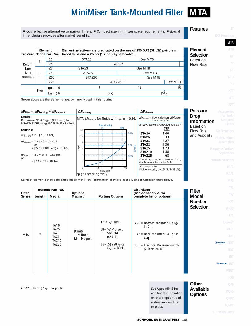
10 3TA10 See MTB25 3TA25Z3 3TAZ3 See MTBZ5 3TAZ5 See MTBZ10 3TAZ10 See MTBZ25 3TAZ25 See MTB
103SCHROEDER INDUSTRIES
FilterModelNumberSelection
OtherAvailableOptions
See Appendix B foradditional informationon these options andinstructions on how to order.
PressureDropInformationBased on Flow Rateand Viscosity
ElementSelectionBased on Flow Rate
Features
MTAMiniMiser Tank-Mounted Filter
TA10TA25TAZ3TAZ5TAZ10TAZ25
MTA 3"(Omit)
= NoneM = Magnet
P8 = 1⁄2” NPTF
S8= 3⁄4”-16 SAEStraight(SAE-8)
B8= IS) 228 G-1⁄2(1⁄2-14 BSPP)
G547 = Two 1⁄8” gauge ports
Shown above are the elements most commonly used in this housing.
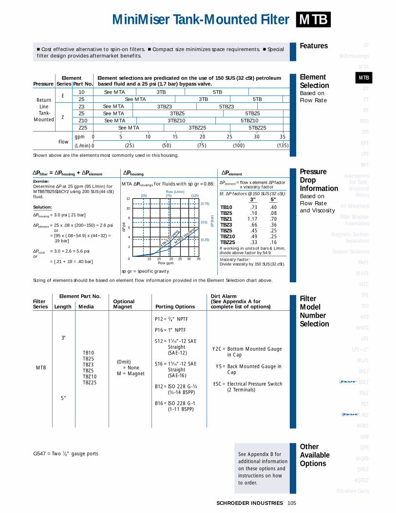
� Cost effective alternative to spin-on filters. � Compact size minimizes space requirements. � Specialfilter design provides aftermarket benefits.
MTA ∆Phousing for fluids with sp gr = 0.86: ∆Pelement= flow x element ∆P factor x viscosity factor
El. ∆P factors @ 150 SUS (32 cSt):3TA
3TA10 1.403TA25 .333TAZ1 4.273TAZ3 2.203TAZ5 1.733TAZ10 1.483TAZ25 .68
If working in units of bars & L/min,divide above factor by 54.9.
Viscosity factor:Divide viscosity by 150 SUS (32 cSt).
∆Pfilter = ∆Phousing + ∆Pelement ∆Phousing ∆Pelement
Exercise:Determine ∆P at 7 gpm (27 L/min) forMTA3TAZ10P8 using 150 SUS (32 cSt) fluid.
Solution:
∆Phousing = 2.0 psi [.14 bar]
∆Pelement = 7 x 1.48 = 10.3 psior
∆Pelement = [27 x (1.48÷54.9) = .73 bar]
∆Ptotal = 2.0 + 10.3 = 12.3 psior∆Pelement = [.14 + .73 = .87 bar]
Sizing of elements should be based on element flow information provided in the Element Selection chart above.
sp gr = specific gravity
12
10
8
6
4
2
(0.75)
(0.5)
(0.25)
0 5 10 15Flow gpm
Flow (L/min) (25) (50)
∆P (b
ar)
∆P p
si
Y2C= Bottom Mounted Gaugein Cap
Y5= Back Mounted Gauge inCap
ESC= Electrical Pressure Switch(2 Terminals)
Element Part No. Dirt AlarmFilter Optional (See Appendix A forSeries Length Media Magnet Porting Options complete list of options)
Element Element selections are predicated on the use of 150 SUS (32 cSt) petroleumPressure Series Part No. based fluid and a 25 psi (1.7 bar) bypass valve.
ReturnLine
-Tank-Mounted
SCHROEDER INDUSTRIES104
FluidCompatibility
Type Fluid Appropriate Schroeder MediaPetroleum Based Fluids All Paper (E) and Synthetic (Z) media
For more information, refer toFluid Compatibility:Fire Resistant Fluids,pages 19 and 20.
Absolute Rating Per ISO 4572/NFPA T3.10.8.8 Abs. Rating wrt ISO 16889 Using automated particle counter (APC) calibrated per ISO 4402 Using APC calibrated per ISO 11171 Dirt Holding
Element ßx ≥ 75 ßx ≥ 100 ßx ≥ 200 ßx(c) ≥ 200 ßx(c) ≥ 1000 Capacity gm
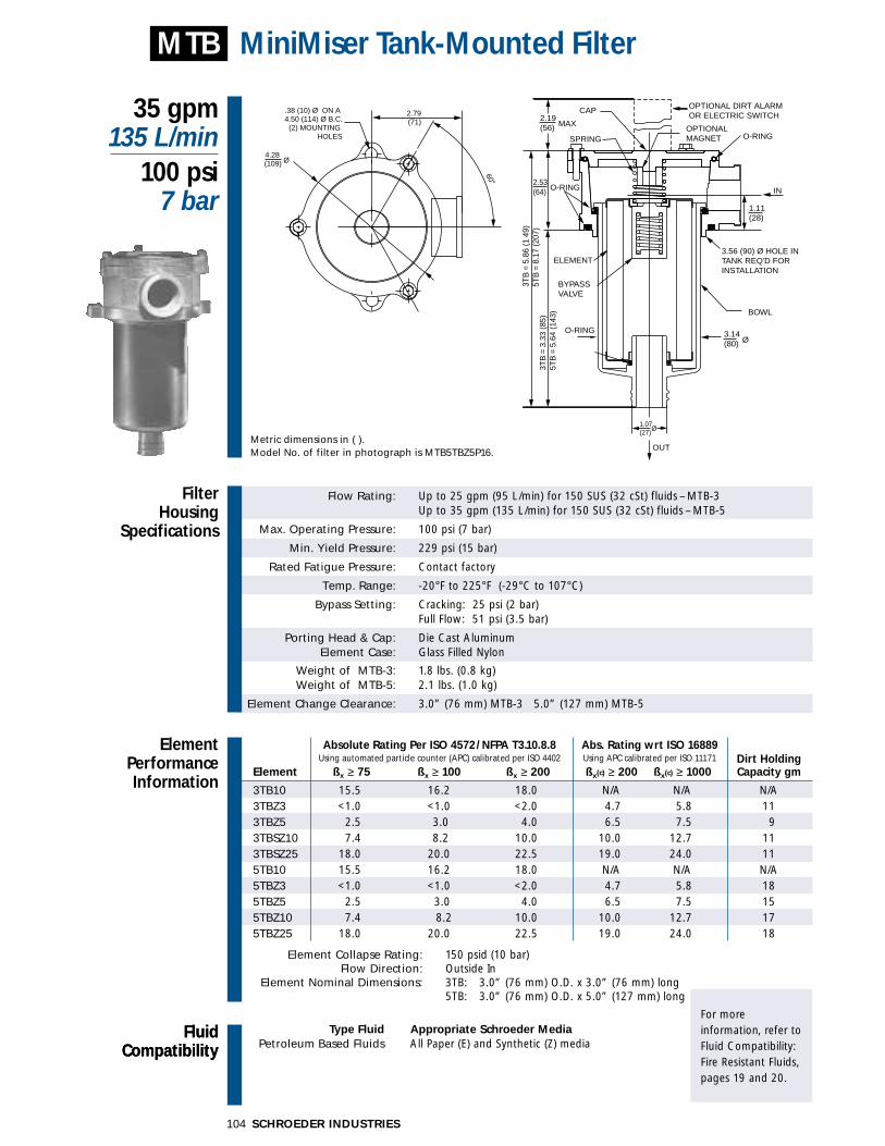
3TB10 15.5 16.2 18.0 N/A N/A N/A3TBZ3 <1.0 <1.0 <2.0 4.7 5.8 113TBZ5 2.5 3.0 4.0 6.5 7.5 93TBSZ10 7.4 8.2 10.0 10.0 12.7 113TBSZ25 18.0 20.0 22.5 19.0 24.0 115TB10 15.5 16.2 18.0 N/A N/A N/A5TBZ3 <1.0 <1.0 <2.0 4.7 5.8 185TBZ5 2.5 3.0 4.0 6.5 7.5 155TBZ10 7.4 8.2 10.0 10.0 12.7 175TBZ25 18.0 20.0 22.5 19.0 24.0 18
Element Collapse Rating: 150 psid (10 bar)Flow Direction: Outside In
Element Nominal Dimensions: 3TB: 3.0” (76 mm) O.D. x 3.0” (76 mm) long5TB: 3.0” (76 mm) O.D. x 5.0” (127 mm) long
Flow Rating: Up to 25 gpm (95 L/min) for 150 SUS (32 cSt) fluids – MTB-3 Up to 35 gpm (135 L/min) for 150 SUS (32 cSt) fluids – MTB-5
Max. Operating Pressure: 100 psi (7 bar)
Min. Yield Pressure: 229 psi (15 bar)
Rated Fatigue Pressure: Contact factory
Temp. Range: -20°F to 225°F (-29°C to 107°C)
Bypass Setting: Cracking: 25 psi (2 bar)Full Flow: 51 psi (3.5 bar)
Porting Head & Cap: Die Cast AluminumElement Case: Glass Filled Nylon
Weight of MTB-3: 1.8 lbs. (0.8 kg)Weight of MTB-5: 2.1 lbs. (1.0 kg)
Element Change Clearance: 3.0” (76 mm) MTB-3 5.0” (127 mm) MTB-5
Filter Housing
Specifications
35 gpm135 L/min
100 psi7 bar
MiniMiser Tank-Mounted Filter
ElementPerformanceInformation
MTB
FluidCompatibility
Metric dimensions in ( ).Model No. of filter in photograph is MTB5TBZ5P16.
60°
.38 (10) Ø ON A 4.50 (114) Ø B.C.
(2) MOUNTING HOLES
2.79(71)
4.28 (109) Ø
3TB
= 3
.33
(85)
5TB
= 5
.64
(143
)
3TB
= 5
.86
(1 4
9)5T
B =
8.1
7 (2
07)
OPTIONAL DIRT ALARMOR ELECTRIC SWITCH
O-RING
BOWL
CAP
SPRING
BYPASS VALVE
ELEMENT
O-RING
O-RING
OPTIONAL MAGNET
3.56 (90) Ø HOLE IN TANK REQ'D FORINSTALLATION
1.11(28)
2.53(64)
1.07Ø
(27)
3.14 Ø(80)
IN
OUT
2.19 MAX(56)
ST
SKB Housings
MTA
MTB
GT
ZT
RT
RTD
RTI
KFT
LRT
BFT
Accessories for Tank-Mounted
Filters
Air Breathers
Filler StrainerAssemblies
Magnetic SuctionSeparators
Suction Strainers
PAF1
MAF1
MF2
TF1
TF3
KF3
WKF3
LF1
LF1—2"
MLF1
SRLT
SRLT
TRLT
RLT
RLT
WRLT
KF8
QF5
MQF5
QFD2
4QFD2
Filtration Carts
STAND-ALONE DISPOSABLE ELEMENT
™™
STAND-ALONE DISPOSABLE ELEMENT
™™
∆Pfilter = ∆Phousing + ∆Pelement ∆Phousing ∆Pelement
105SCHROEDER INDUSTRIES
FilterModelNumberSelection
OtherAvailableOptions
See Appendix B foradditional informationon these options andinstructions on how to order.
PressureDropInformationBased on Flow Rateand Viscosity
ElementSelectionBased on Flow Rate
Features
MTBMiniMiser Tank-Mounted Filter
TB10TB25TBZ3TBZ5TBZ10TBZ25
MTB
3"
5"
(Omit) = None
M = Magnet
P12= 3⁄4” NPTF
P16= 1” NPTF
S12= 11⁄16"-12 SAEStraight (SAE-12)
S16 = 15⁄16"-12 SAEStraight (SAE-16)
B12= ISO 228 G-3⁄4(3⁄4-14 BSPP)
B16= ISO 228 G-1 (1-11 BSPP)
G547 = Two 1⁄8” gauge ports
Shown above are the elements most commonly used in this housing.
� Cost effective alternative to spin-on filters. � Compact size minimizes space requirements. � Specialfilter design provides aftermarket benefits.
MTA ∆Phousings for fluids with sp gr =0.86: ∆Pelement= flow x element ∆P factor x viscosity factor
El. ∆P factors @ 150 SUS (32 cSt):3" 5"
TB10 .73 .40TB25 .10 .08TBZ1 1.17 .70TBZ3 .66 .36TBZ5 .45 .25TBZ10 .49 .25TBZ25 .33 .16If working in units of bars & L/min,divide above factor by 54.9.
Viscosity factor:Divide viscosity by 150 SUS (32 cSt).
Exercise:Determine ∆P at 25 gpm (95 L/min) forMTB5TB25S16CY2 using 200 SUS (44 cSt)fluid.
Solution:
∆Phousing = 3.0 psi [.21 bar]
∆Pelement = 25 x .08 x (200÷150) = 2.6 psior
∆Pelement = [95 x (.08÷54.9) x (44÷32) = .19 bar]
∆Ptotal = 3.0 + 2.6 = 5.6 psior∆Pelement = [.21 + .19 = .40 bar]
Sizing of elements should be based on element flow information provided in the Element Selection chart above.
sp gr = specific gravity
0 10 15 20 25 30 35Flow gpm
Flow (L/min)(25) (75) (125)
∆P (b
ar)
∆P p
si
12
10
8
6
4
2
(0.75)
(0.5)
(0.25)M
TB-5 Housin
g
MTB
-3 H
ousing
Y2C= Bottom Mounted Gaugein Cap
Y5= Back Mounted Gauge inCap
ESC= Electrical Pressure Switch(2 Terminals)
E
Z
Flowgpm
(L/min) 0
Element Element selections are predicated on the use of 150 SUS (32 cSt) petroleumPressure Series Part No. based fluid and a 25 psi (1.7 bar) bypass valve.
ReturnLine
-Tank-Mounted
0 5 10 15 20 25 30 35
(25) (50) (75) (100) (135)
10 See MTA 3TB 5TB25 See MTA 3TB 5TBZ3 See MTA 3TBZ3 5TBZ3Z5 See MTA 3TBZ5 5TBZ5Z10 See MTA 3TBZ10 5TBZ10Z25 See MTA 3TBZ25 5TBZ25
Element Part No. Dirt AlarmFilter Optional (See Appendix A forSeries Length Media Magnet Porting Options complete list of options)

FluidCompatibility
Type Fluid Appropriate Schroeder MediaPetroleum Based Fluids All Paper (E) and Synthetic (Z) media
High Water Content Z10, Z25Invert Emulsions Z10, Z25
Water Glycols Z10, Z25Note: Contact factory regarding use of E Media in High Water Content, Invert Emulsion and Water Glycol Applications.
For more information, refer toFluid Compatibility:Fire Resistant Fluids,pages 19 and 20.
SCHROEDER INDUSTRIES106
Flow Rating: Up to 20 gpm (75 L/min) for 150 SUS (32 cSt) fluids
Max. Operating Pressure: 85 psi (6 bar)
Min. Yield Pressure: Contact factory
Rated Fatigue Pressure: Contact factory
Temp. Range: -20°F to 180°F (-29°C to 82°C)
Bypass Setting: Cracking: 35 psi (2 bar)
Porting Head & Cap: Glass Fiber Reinforced PlasticElement Case: Glass Fiber Reinforced Plastic
Weight of GT-4G: 0.8 lbs. (0.4 kg)Weight of GT-8G: 1.1 lbs. (0.5 kg)
Element Change Clearance: 4.75” (125 mm) 8.75” (225 mm)
Absolute Rating Per ISO 4572/NFPA T3.10.8.8 Dirt Holding Element ßx ≥ 75 ßx ≥ 100 ßx ≥ 200 Capacity gm
4G10 30 — — 5
8G10 30 — — 7
4GZ10 10 — — 5
8GZ10 10 — — 8
8GZ25 20 — — 9
Flow Direction: Outside InElement Nominal Dimensions: 1.75” (45 mm) O.D. x 4.0” (105 mm) long
2.5” (65 mm) O.D. x 8.0” (200 mm) long
Filter Housing
Specifications
20 gpm75 L/min
85 psi6 bar
Tank-Mounted Filter with Integral Air Breather
ElementPerformanceInformation
GT
Metric dimensions in ( ).Model No. of filter in photograph is GT8G10Y6A.
(22)
(65)
Ø(51)
(76)
GT-
8G =
7.1
6 (1
82)
GT-
8G =
9.7
2 (2
47)
GT-
4G =
3.3
5 (8
5)
GT-
4G =
5.9
1 (1
50)
GT-8G = .81 (21) ØGT-4G = .69 (18) Ø
TO INSTALLEXTENSION TUBE
2.56
3.00 Ø
PROVIDES CAPABILITYOUTLET FITTING
2.00
OIL SEPARATOR
O-RING SEAL
GAUGEDIRT ALARMCOLOR CODED
IN RESERVOIR2.36 (60) Ø HOLE
.86(108) (88)
(65) (59)
MOUNTING HOLESP = .75 PSI @ 3.2 SCFM
AIR BREATHER
2.56 2.32
4.25 3.46
DISPOSABLE.43 (11) Ø (2)
AA
IN
OUT
VIEW A-A
3.00(76)

ST
SKB Housings
MTA
MTB
GT
ZT
RT
RTD
RTI
KFT
LRT
BFT
Accessories for Tank-Mounted
Filters
Air Breathers
Filler StrainerAssemblies
Magnetic SuctionSeparators
Suction Strainers
PAF1
MAF1
MF2
TF1
TF3
KF3
WKF3
LF1
LF1—2"
MLF1
SRLT
SRLT
TRLT
RLT
RLT
WRLT
KF8
QF5
MQF5
QFD2
4QFD2
Filtration Carts
STAND-ALONE DISPOSABLE ELEMENT
™™
STAND-ALONE DISPOSABLE ELEMENT
™™
FilterModelNumberSelection
OtherAvailableOptions
See Appendix B foradditional informationon these options andinstructions on how to order.
PressureDropInformationBased on Flow Rateand Viscosity
ElementSelectionBased on Flow Rate
Features
107SCHROEDER INDUSTRIES
GTTank-Mounted Filter with Integral Air Breather
Element Part No.Dirt Alarm
Filter Seal (See Appendix forSeries Length Media Material Porting complete list of options) Other
G10GZ10
G10GZ10GZ25
GT (Omit) = Buna N
A = Dipstick
Omit =
Inlet: Male hose barb connection
Outlet: Non-threaded connection21⁄32” I.D.
Element Element selections are predicated on the use of 150 SUS (32 cSt) Pressure Series Part No. petroleum based fluid and a 35 psi bypass valve.
E4G10 & 8G10 4G10 8G10(Cellulose)
Z 4GZ10 & 8GZ10 4GZ10 8GZ10(Glass) 8GZ20 8GZ20
Flow gpm 0 5 10 15 20
(L/min) 0 25 50 75
Shown above are the elements most commonly used in this housing.
� Constructed of glass fiber reinforced plastic. � Built-in disposable air breather. � Cost saving hosebarb connection.
ReturnLine
-Tank-Mounted
GT ∆Phousing for fluids with sp gr = 0.86: ∆Pelement= flow x element ∆P factor x viscosity factor
El. ∆P factors @ 150 SUS (32 cSt):
4G10 .404GZ10 1.008G10 .188GZ10 .328GZ20 .25
If working in units of bars & L/min,divide above factor by 54.9.
Viscosity factor:Divide viscosity by 150 SUS (32 cSt).
∆Pfilter = ∆Phousing + ∆Pelement ∆Phousing ∆Pelement
Exercise:Determine ∆P at 10 gpm (38 L/min) forGT8G10 using 200 SUS (44 cSt) fluid.
Solution:
∆Phousing = 1.5 psi [.12 bar]
∆Pelement = 10 x .18 x (200÷150) = 2.4 psior
∆Pelement = [38 x (.18÷54.9) x (44÷32) = .17 bar]
∆Ptotal = 1.5 + 2.4 = 3.9 psior
∆Pelement = [.12 + .17 = .29 bar]
Sizing of elements should be based on element flow information provided in the Element Selection chart above.
sp gr = specific gravity
(0.25)
(0.50)
(25) (50) (75)8
6
4
2
0 0 5 10 15 20
Flow gpm
Flow (L/min)
∆P (b
ar)
∆P p
si
Y6 = Color Coded Gauge
ES6 = Electric Switch
4”
8”
None
FluidCompatibility
Type Fluid Appropriate Schroeder MediaPetroleum Based Fluids All Paper (E) and Synthetic (Z) media
High Water Content Z1, Z3, Z5, Z10, Z25Invert Emulsions Z10, Z25
Water Glycols Z3, Z5, Z10, Z25Phosphate Esters All Z media with EPR Seals
Skydrol Z3H.5, Z5H.5, Z10H.5 and Z25H.5 Note: Contact factory regarding use of E Media in High Water Content, Invert Emulsion and Water Glycol Applications.
For more information, refer toFluid Compatibility:Fire Resistant Fluids,pages 19 and 20.
SCHROEDER INDUSTRIES108
Absolute Rating Per ISO 4572/NFPA T3.10.8.8 Abs. Rating wrt ISO 16889 Using automated particle counter (APC) calibrated per ISO 4402 Using APC calibrated per ISO 11171 Dirt Holding
Element ßx ≥ 75 ßx ≥ 100 ßx ≥ 200 ßx(c) ≥ 200 ßx(c) ≥ 1000 Capacity gm
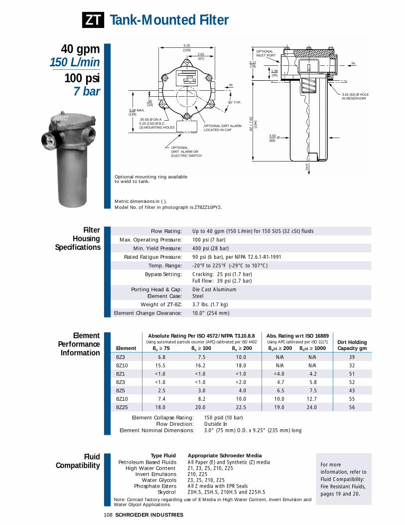
8Z3 6.8 7.5 10.0 N/A N/A 39
8Z10 15.5 16.2 18.0 N/A N/A 32
8Z1 <1.0 <1.0 <1.0 <4.0 4.2 51
8Z3 <1.0 <1.0 <2.0 4.7 5.8 52
8Z5 2.5 3.0 4.0 6.5 7.5 43
8Z10 7.4 8.2 10.0 10.0 12.7 55
8Z25 18.0 20.0 22.5 19.0 24.0 56
Element Collapse Rating: 150 psid (10 bar)Flow Direction: Outside In
Element Nominal Dimensions: 3.0” (75 mm) O.D. x 9.25” (235 mm) long
Flow Rating: Up to 40 gpm (150 L/min) for 150 SUS (32 cSt) fluids
Max. Operating Pressure: 100 psi (7 bar)
Min. Yield Pressure: 400 psi (28 bar)
Rated Fatigue Pressure: 90 psi (6 bar), per NFPA T2.6.1-R1-1991
Temp. Range: -20°F to 225°F (-29°C to 107°C)
Bypass Setting: Cracking: 25 psi (1.7 bar)Full Flow: 39 psi (2.7 bar)
Porting Head & Cap: Die Cast AluminumElement Case: Steel
Weight of ZT-8Z: 3.7 lbs. (1.7 kg)
Element Change Clearance: 10.0” (254 mm)
Filter Housing
Specifications
40 gpm150 L/min
100 psi7 bar
Tank-Mounted Filter
ElementPerformanceInformation
ZT
IN
.35 (9) Ø ON A5.25 (133) Ø B.C. (3) MOUNTING HOLES
OPTIONALDIRT ALARM ORELECTRIC SWITCH
OPTIONAL DIRT ALARM LOCATED IN CAP
30° TYP.
2.62(133)5.25
(67)
(14)
(149)5.88 MAX.
.56
OU
T
IN
3.62 (92) Ø HOLEIN RESERVOIR
OPTIONAL INLET PORT
3.50
(79)
(35)
(194
)
(89)Ø
8Z =
7.6
2
3.12
1.38
Metric dimensions in ( ).Model No. of filter in photograph is ZT8ZZ10PY2.
Optional mounting ring availableto weld to tank.

ST
SKB Housings
MTA
MTB
GT
ZT
RT
RTD
RTI
KFT
LRT
BFT
Accessories for Tank-Mounted
Filters
Air Breathers
Filler StrainerAssemblies
Magnetic SuctionSeparators
Suction Strainers
PAF1
MAF1
MF2
TF1
TF3
KF3
WKF3
LF1
LF1—2"
MLF1
SRLT
SRLT
TRLT
RLT
RLT
WRLT
KF8
QF5
MQF5
QFD2
4QFD2
Filtration Carts
STAND-ALONE DISPOSABLE ELEMENT
™™
STAND-ALONE DISPOSABLE ELEMENT
™™
FilterModelNumberSelection
OtherAvailableOptions
See Appendix B foradditional informationon these options andinstructions on how to order.
PressureDropInformationBased on Flow Rateand Viscosity
ElementSelectionBased on Flow Rate
Features
109SCHROEDER INDUSTRIES
ZTTank-Mounted Filter
Z3**Z10**Z25**
ZZ1ZZ3ZZ5ZZ10ZZ25
ZT 8”
(Omit) = Buna N
H = EPR*
P = 1” NPTF
PP = Dual 1”NPTF
S = 15⁄16”-12 SAEStraight(SAE-16)
SS = Dual 15⁄16”-12SAE Straight(SAE-16)
B = ISO 228 G-1(1-11 BSPP)
BB= Dual ISO 228 G-1(1-11 BSPP)
Element Element selections are predicated on the use of 150 SUS (32 cSt)Pressure Series Part No. petroleum based fluid and a 25 psi (1.7 bar) bypass valve.
E8Z3 paper 8Z3 (cellulose media)
Media 8Z10 paper 8Z10 (cellulose media)8Z25 paper 8Z25 (cellulose media)
Z
8ZZ3 8ZZ3
Media8ZZ5 8ZZ58ZZ10 8ZZ108ZZ25 8ZZ25
Flowgpm 0 10 20 30 40
(L/min) 0 50 100 150
Shown above are the elements most commonly used in this housing.
� Dual inlet porting available.
ReturnLine
-Tank-Mounted
ZT ∆Phousing for fluids with sp gr = 0.86: ∆Pelement= flow x element ∆P factor x viscosity factor
El. ∆P factors @ 150 SUS (32 cSt):
8Z3 .258Z10 .098Z25 .028ZZ1 .378ZZ3 .218ZZ5 .138ZZ10 .118ZZ25 .08
If working in units of bars & L/min,divide above factor by 54.9.
Viscosity factor:Divide viscosity by 150 SUS (32 cSt).
∆Pfilter = ∆Phousing + ∆Pelement ∆Phousing ∆Pelement
Exercise:Determine ∆P at 20 gpm (76 L/min) forZT8ZZ1PES using 200 SUS (44 cSt) fluid.
Solution:
∆Phousing = 1 psi [.07 bar]
∆Pelement = 20 x .37 x (200÷150) = 9.8 psior
∆Pelement = [76 x (.37÷54.9) x (44÷32) = 0.7 bar]
∆Ptotal = 1.0 + 9.8 = 10.8 psior
∆Pelement = [.07 + .7 = .77 bar]
Sizing of elements should be based on element flow information provided in the Element Selection chart above.
sp gr = specific gravity
(0.25)
(0.50)
(25) (75) (125)10
8
6
4
2
0 0 10 20 30 40
Flow gpm
Flow (L/min)
∆P (b
ar)
∆P p
si
Y2 = Back MountedTri-Color Gauge
Y2C = Bottom MountedGauge in Cap
Y5 = Back MountedGauge in Cap
ES = Electric Switch
ES1 = Heavy-DutyElectric Switchwith ConduitConnection
**When “H” seals are ordered all aluminum filter parts are anodized.**Only available with Buna N seals.
Element Part No.Dirt Alarm
Filter Seal Inlet Outlet (See Appendix A forSeries Length Media Material Porting Porting complete list of options)
(Omit)= Non-
threaded
OP = 11⁄2” NPTFMale
See also “Accessories for Tank-Mounted Filters” section.

FluidCompatibility
Type Fluid Appropriate Schroeder MediaPetroleum Based Fluids All Paper (E) and Synthetic (Z) Media
High Water Content Z1, Z3, Z5, Z10, Z25Invert Emulsions Z10, Z25
Water Glycols Z3, Z5, Z10, Z25Phosphate Esters All Z Media with EPR Seals, K3H and K10H E Media
Skydrol Z3H.5, Z5H.5, Z10H.5, Z25H.5 and WH.5 Note: Contact factory regarding use of E Media in High Water Content, Invert Emulsion and Water Glycol Applications.
For more information, refer toFluid Compatibility:Fire Resistant Fluids,pages 19 and 20.
SCHROEDER INDUSTRIES110
Absolute Rating Per ISO 4572/NFPA T3.10.8.8 Abs. Rating wrt ISO 16889 Using automated particle counter (APC) calibrated per ISO 4402 Using APC calibrated per ISO 11171 Dirt Holding
Element ßx ≥ 75 ßx ≥ 100 ßx ≥ 200 ßx(c) ≥ 200 ßx(c) ≥ 1000 Capacity gm
K3 6.8 7.5 10.0 N/A N/A 54
K10 15.5 16.2 18.0 N/A N/A 44
KZ1 <1.0 <1.0 <1.0 <4.0 4.2 112
KZ3 <1.0 <1.0 <2.0 4.7 5.8 115
KZ5 2.5 3.0 4.0 6.5 7.5 86
KZ10 7.4 8.2 10.0 10.0 12.7 108
KZ25 18.0 20.0 22.5 19.0 24.0 93
Element Collapse Rating: 150 psid (10 bar)Flow Direction: Outside In See RTI, page 114 for inside out flow version.
Element Nominal Dimensions: 4.0” (100 mm) O.D. x 9.0” (230 mm) long
Flow Rating: Up to 100 gpm (380 L/min) for 150 SUS (32 cSt) fluids
Max. Operating Pressure: 100 psi (7 bar)
Min. Yield Pressure: 400 psi (28 bar)
Rated Fatigue Pressure: 90 psi (6 bar), per NFPA T2.6.1-1974
Temp. Range: -20°F to 225°F (-29°C to 107°C)
Bypass Setting: Cracking: 25 psi (1.7 bar)Full Flow: 48 psi (3.3 bar)
Porting Head & Cap: Die Cast AluminumElement Case: Steel
Weight of RT-1K: 11.4 lbs. (5.2 kg)Weight of RT-2K: 14.5 lbs. (6.6 kg)
Element Change Clearance: 8.0” (205 mm)
Filter Housing
Specifications
100 gpm380 L/min
100 psi7 bar
Tank-Mounted Filter
ElementPerformanceInformation
RT
Metric dimensions in ( ).Model No. of filter in photograph is RT1K10S24NP16CY2.
2.59(66)
5.06 (129) ØHOLE IN TANK
4.50 (114)
.44 (11) Ø ON A6.25 (159) Ø B.C.(4) MOUNTING HOLES
(110)4.31
Ø
GASKET.12 (3) THICK
OPTIONALCHECK VALVE
FOR INSTALLATION
OPTIONALINLETPORT
OPTIONAL DIRT ALARMOR ELECTRIC SWITCH
45° TYP.
IN
OUT
6.25(159)
MAX.
SEE CHARTPORT TO PORT
7.00(178)
Ø
1K =
8.8
1 (2
24)
2K =
18.
00 (
457)
3K =
27.
31 (
694)
CSEE CHART
TO TANK TOP
.88(22)
Optional mounting ring available to weld to tank.
11⁄4”, 11⁄2” 11⁄2” PortsStandard Ports 4-Bolt Flange Only 2” Ports
Port to Port 6.38” 7.12” 7.56” (P, S, B)7.38” (F)
CL to Casting Base 1.56” 1.75” 1.81”CL to Tank Top 1.88” 2.06” 2.12”
ST
SKB Housings
MTA
MTB
GT
ZT
RT
RTD
RTI
KFT
LRT
BFT
Accessories for Tank-Mounted
Filters
Air Breathers
Filler StrainerAssemblies
Magnetic SuctionSeparators
Suction Strainers
PAF1
MAF1
MF2
TF1
TF3
KF3
WKF3
LF1
LF1—2"
MLF1
SRLT
SRLT
TRLT
RLT
RLT
WRLT
KF8
QF5
MQF5
QFD2
4QFD2
Filtration Carts
STAND-ALONE DISPOSABLE ELEMENT
™™
STAND-ALONE DISPOSABLE ELEMENT
™™
111SCHROEDER INDUSTRIES
FilterModelNumberSelection
OtherAvailableOptions
See Appendix B foradditional informationon these options andinstructions on how to order.
PressureDropInformationBased on Flow Rateand Viscosity
ElementSelectionBased on Flow Rate
Features
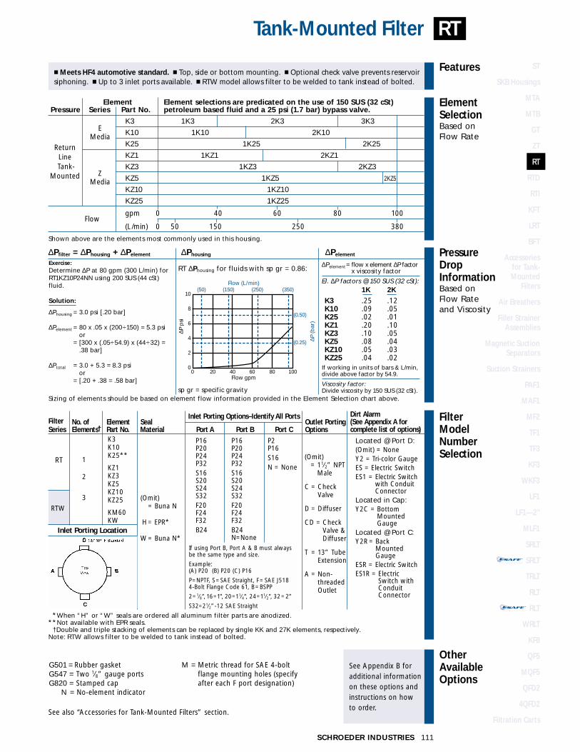
RTTank-Mounted Filter
Filter No. of Element SealInlet Porting Options–Identify All Ports
Outlet PortingSeries Elements† Part No. Material Port A Port B Port C Options
K3K10K25**
KZ1KZ3KZ5KZ10KZ25
KM60KW
1
2
3
RTW
(Omit) = Buna N
H= EPR*
W= Buna N*
P16P20P24P32S16S20S24S32F20F24F32B24
P16P20P24P32S16S20S24S32F20F24F32B24N=None
P2P16S16N = None
(Omit)= 11⁄2” NPT
Male
C = CheckValve
D = Diffuser
CD = CheckValve &Diffuser
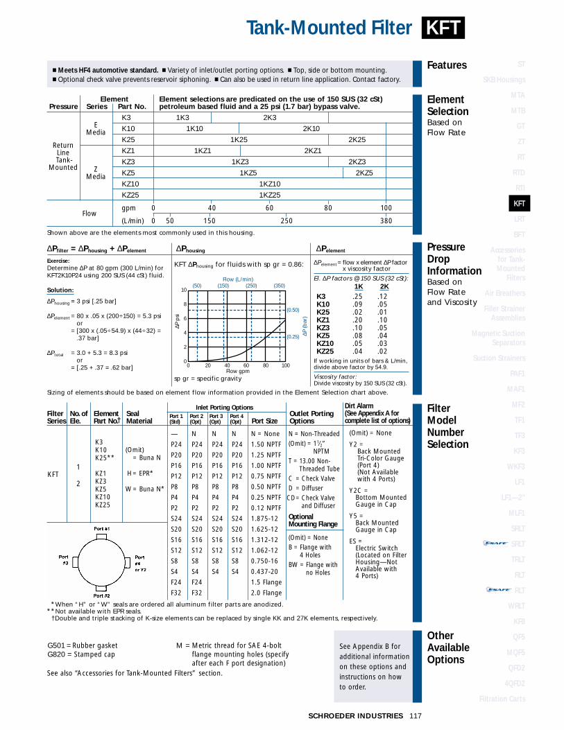
T = 13” TubeExtension
A = Non-threadedOutlet
Element Element selections are predicated on the use of 150 SUS (32 cSt) Pressure Series Part No. petroleum based fluid and a 25 psi (1.7 bar) bypass valve.
EK3 1K3 2K3 3K3
Media K10 1K10 2K10
K25 1K25 2K25
KZ1 1KZ1 2KZ1
ZKZ3 1KZ3 2KZ3
Media KZ5 1KZ5 2KZ5
KZ10 1KZ10
KZ25 1KZ25
Flowgpm 0 40 60 80 100
(L/min) 0 50 150 250 380
Shown above are the elements most commonly used in this housing.
� Meets HF4 automotive standard. � Top, side or bottom mounting. � Optional check valve prevents reservoirsiphoning. � Up to 3 inlet ports available. � RTW model allows filter to be welded to tank instead of bolted.
ReturnLine
-Tank-Mounted
RT ∆Phousing for fluids with sp gr = 0.86: ∆Pelement= flow x element ∆P factor x viscosity factor
El. ∆P factors @ 150 SUS (32 cSt):1K 2K
K3 .25 .12K10 .09 .05K25 .02 .01KZ1 .20 .10KZ3 .10 .05KZ5 .08 .04KZ10 .05 .03KZ25 .04 .02
If working in units of bars & L/min,divide above factor by 54.9.
Viscosity factor:Divide viscosity by 150 SUS (32 cSt).
∆Pfilter = ∆Phousing + ∆Pelement ∆Phousing ∆Pelement
Exercise:Determine ∆P at 80 gpm (300 L/min) forRT1KZ10P24NN using 200 SUS (44 cSt)fluid.
Solution:
∆Phousing = 3.0 psi [.20 bar]
∆Pelement = 80 x .05 x (200÷150) = 5.3 psior
∆Pelement = [300 x (.05÷54.9) x (44÷32) = .38 bar]
∆Ptotal = 3.0 + 5.3 = 8.3 psior
∆Pelement = [.20 + .38 = .58 bar]
Sizing of elements should be based on element flow information provided in the Element Selection chart above.sp gr = specific gravity
(0.25)
(0.50)
(50) (150) (250) (350)10
8
6
4
2
0 0 20 40 60 80 100
Flow gpm
Flow (L/min)
∆P (b
ar)
∆P p
si
Located @ Port D:(Omit) = NoneY2 = Tri-color GaugeES = Electric SwitchES1 = Electric Switch
with ConduitConnector
Located in Cap:Y2C = Bottom
MountedGauge
Located @ Port C:Y2R = Back
MountedGauge
ESR = Electric SwitchES1R = Electric
Switch withConduitConnector
**When “H” or “W” seals are ordered all aluminum filter parts are anodized.**Not available with EPR seals.
†Double and triple stacking of elements can be replaced by single KK and 27K elements, respectively.Note: RTW allows filter to be welded to tank instead of bolted.
Inlet Porting Location
If using Port B, Port A & B must alwaysbe the same type and size.
Example:(A) P20 (B) P20 (C) P16
P=NPTF, S=SAE Straight, F= SAE J518 4-Bolt Flange Code 61, B=BSPP
2=1⁄8”, 16=1”, 20=11⁄4”, 24=11⁄2”, 32=2”
S32=21⁄2”-12 SAE Straight
G501 = Rubber gasketG547 = Two 1⁄8” gauge portsG820 = Stamped cap
N = No-element indicator
M = Metric thread for SAE 4-boltflange mounting holes (specifyafter each F port designation)
See also “Accessories for Tank-Mounted Filters” section.
Dirt Alarm(See Appendix A forcomplete list of options)
RT

SCHROEDER INDUSTRIES112
Flow Rating: Up to 100 gpm (380 L/min) for 150 SUS (32 cSt) fluids
Max. Operating Pressure: 100 psi (7 bar)
Min. Yield Pressure: 400 psi (28 bar)
Rated Fatigue Pressure: 90 psi (6 bar), per NFPA T2.6.1.R1-1991
Temp. Range: -20°F to 225°F (-29°C to 107°C)
Bypass Setting: Cracking: 25 psi (1.7 bar)Full Flow: 48 psi (3.3 bar)
Porting Head & Cap: Die Cast AluminumElement Case: Steel
Weight of RTD-1K: 29.2 lbs. (13.3 kg)Weight of RTD-2K: 35.4 lbs. (16.1 kg)
Element Change Clearance: 8.0” (205 mm)
Filter Housing
Specifications
100 gpm380 L/min
100 psi7 bar
Tank-Mounted Duplex FilterRTD
Metric dimensions in ( ).Model No. of filter in photograph is RTD2KZ10P24.
21.59
14.47
OUT
4.50Ø
1 E
LEM
EN
T 8
.81
(224
)
2 E
LEM
EN
T 1
8.00
(45
7)3
ELE
ME
NT
27.
31 (
694)
5.06 (129)DIA. HOLEIN TANK
IN
OUT
ELE
ME
NT
RE
MO
VA
LR
EQ
UIR
ED
FO
R
MIN
. CLE
AR
AN
CE
8.00
2.59
2.06
4.31
6.25 [159]MAX
OPTIONAL DIRT ALARM OR ELECTRIC SWITCH
BACK
FRONT
DIRT ALARM LOCATIONS
INFRONT
BACK
FluidCompatibility
Type Fluid Appropriate Schroeder MediaPetroleum Based Fluids All Paper (E) and Synthetic (Z) Media
High Water Content Z1, Z3, Z5, Z10, Z25Invert Emulsions Z10, Z25
Water Glycols Z3, Z5, Z10, Z25Phosphate Esters All Z Media with EPR Seals, K3H and K10H E Media
Skydrol Z3H.5, Z5H.5, Z10H.5, Z25H.5 and WH.5 Note: Contact factory regarding use of E Media in High Water Content, Invert Emulsion and Water Glycol Applications.
For more information, refer toFluid Compatibility:Fire Resistant Fluids,pages 19 and 20.
Absolute Rating Per ISO 4572/NFPA T3.10.8.8 Abs. Rating wrt ISO 16889 Using automated particle counter (APC) calibrated per ISO 4402 Using APC calibrated per ISO 11171 Dirt Holding
Element ßx ≥ 75 ßx ≥ 100 ßx ≥ 200 ßx(c) ≥ 200 ßx(c) ≥ 1000 Capacity gm
K3 6.8 7.5 10.0 N/A N/A 54
K10 15.5 16.2 18.0 N/A N/A 44
KZ1 <1.0 <1.0 <1.0 <4.0 4.2 112
KZ3 <1.0 <1.0 <2.0 4.7 5.8 115
KZ5 2.5 3.0 4.0 6.5 7.5 86
KZ10 7.4 8.2 10.0 10.0 12.7 108
KZ25 18.0 20.0 22.5 19.0 24.0 93
Element Collapse Rating: 150 psid (10 bar)Flow Direction: Outside In
Element Nominal Dimensions: 4.0” (100 mm) O.D. x 9.0” (230 mm) long
ElementPerformanceInformation
NEWPRODUCT

ElementSelectionBased on Flow Rate
Element Element selections are predicated on the use of 150 SUS (32 cSt) Pressure Series Part No. petroleum based fluid and a 25 psi (1.7 bar) bypass valve.
EK3 1K3 2K3 3K3
Media K10 1K10 2K10
K25 1K25 2K25
KZ1 1KZ1 2KZ1
ZKZ3 1KZ3 2KZ3
Media KZ5 1KZ5 2KZ5
KZ10 1KZ10
KZ25 1KZ25
Flowgpm 0 40 60 80 100
(L/min) 0 50 150 250 380
Shown above are the elements most commonly used in this housing.
ReturnLine
-Tank-Mounted
ST
SKB Housings
MTA
MTB
GT
ZT
RT
RTD
RTI
KFT
LRT
BFT
Accessories for Tank-Mounted
Filters
Air Breathers
Filler StrainerAssemblies
Magnetic SuctionSeparators
Suction Strainers
PAF1
MAF1
MF2
TF1
TF3
KF3
WKF3
LF1
LF1—2"
MLF1
SRLT
SRLT
TRLT
RLT
RLT
WRLT
KF8
QF5
MQF5
QFD2
4QFD2
Filtration Carts
STAND-ALONE DISPOSABLE ELEMENT
™™
STAND-ALONE DISPOSABLE ELEMENT
™™
113SCHROEDER INDUSTRIES
FilterModelNumberSelection
OtherAvailableOptions
See Appendix B foradditional informationon these options andinstructions on how to order.
PressureDropInformationBased on Flow Rateand Viscosity
Features
RTDTank-Mounted Duplex Filter
G547 = Two 1⁄8” gauge portsG820 = Stamped cap
M = Metric thread for SAE 4-boltflange mounting holes (specify after each F port designation)
See also “Accessories for Tank-Mounted Filters” section.
� Diversion valve allows for uninterrupted flow during element change. � Meets HF4 automotive standard.� Top, side or bottom mounting. � Optional check valve prevents reservoir siphoning.
RTD ∆Phousing for fluids with sp gr = 0.86: ∆Pelement= flow x element ∆P factor x viscosity factor
El. ∆P factors @ 150 SUS (32 cSt):1K 2K
K3 .25 .12K10 .09 .05K25 .02 .01KZ1 .20 .10KZ3 .10 .05KZ5 .08 .04KZ10 .05 .03KZ25 .04 .02
If working in units of bars & L/min,divide above factor by 54.9.
Viscosity factor:Divide viscosity by 150 SUS (32 cSt).
∆Pfilter = ∆Phousing + ∆Pelement ∆Phousing ∆Pelement
Sizing of elements should be based on element flow information provided in the Element Selection chart above.sp gr = specific gravity
(0.25)
16
14
12
10
8
6
4
2
0
(0.50)
(0.75)
(1.00)∆P
(bar
)
∆P p
si
(100) (200)
0 25 50 75 100Flow gpm
Flow (L/min)(300)
PORT TO PORT
ELEMENT SIZING
K3K10K25
KZ1KZ3KZ5KZ10KZ25
KM60KW
RTD
1
2
3
(Omit) = Buna N
H = EPR(AluminumPartsAnodized)
P16 =1” NPTFP20 =11⁄4” NPTFP24 =11⁄2” NPTFP32 =2 NPTF
S16 =15⁄16”-12 SAEStraight (SAE-16)
S20 =15⁄8”-12 SAE Straight(SAE-20)
S24 =17⁄8 -12 SAE Straight(SAE-24)
S32 =21⁄2”-12 SAE Straight(SAE-32)
F20 =11⁄4” SAE J518 SplitFlange Code 61
F24 =11⁄2” SAE J518 SplitFlange Code 61
F32 =2” SAE J518 SplitFlange Code 61
B24 =ISO 228 G11⁄2”
Located in Front:(Omit) = NoneY2 = Tri-color GaugeES = Electric SwitchES1 = Electric Switch
with ConduitConnector
Located in Cap:Y2C = Bottom Mounted
Gauge
Located in Back:Y2R = Back Mounted
GaugeESR = Electric SwitchES1R = Electric Switch
with ConduitConnector
Filter Element Element Seal Inlet OutletSeries Length Model No. Material Porting Options Porting Options
(Omit) = 1.50 NPTM
A = NonThreaded
C = Check Valve
D = Diffuser
CD = Check Valveand Diffuser
T = 13" TubeExtension
Dirt Alarm(See Appendix A forcomplete list of options)
NEWPRODUCT
The ∆P housing curve labeled“Element Sizing” is the pressuredrop between the inlet and outlet areas of the filter’s bypass valveand should be used for filter sizing.The “Port to Port” ∆P takes intoconsideration any manifolds and/orspecial valving. This pressure dropcan be significantly higher due tothese additional flow constrictions.Although this ∆P does not affectthe performance of the filter, itshould be considered for overallsystem design.

FluidCompatibility
Type Fluid Appropriate Schroeder MediaPetroleum Based Fluids All Paper (E) and Synthetic (Z) Media
High Water Content Z1, Z3, Z5, Z10, Z25Invert Emulsions Z10, Z25
Water Glycols Z3, Z5, Z10, Z25Phosphate Esters All Z Media with EPR Seals, K3H and K10H E Media
Skydrol Z3H.5, Z5H.5, Z10H.5, Z25H.5 and WH.5 Note: Contact factory regarding use of E Media in High Water Content, Invert Emulsion and Water Glycol Applications.
For more information, refer toFluid Compatibility:Fire Resistant Fluids,pages 19 and 20.
SCHROEDER INDUSTRIES114
Absolute Rating Per ISO 4572/NFPA T3.10.8.8 Abs. Rating wrt ISO 16889 Dirt Holding Using automated particle counter (APC) calibrated per ISO 4402 Using APC calibrated per ISO 11171 Capacity gm
Element ßx ≥ 75 ßx ≥ 100 ßx ≥ 200 ßx(c) ≥ 200 ßx(c) ≥ 1000 K/KK/27K
KIZ1 <1.0 <1.0 <1.0 <4.0 4.2 85/181/276
KIZ3 <1.0 <1.0 <2.0 4.7 5.8 88/185/283
KIZ10 <7.4 <8.2 <10.0 10.0 12.7 82/174/266
Element Collapse Rating: 100 psid (7 bar)Flow Direction: Inside Out
Element Nominal Dimensions: KI: 4.0” (100 mm) O.D. x 9.0” (230 mm) longKKI: 4.0” (100 mm) O.D. x 18.0” (460 mm) long27KI: 4.0” (100 mm) O.D. x 27.0” (690 mm) long
Flow Rating: Up to 120 gpm (455 L/min) for 150 SUS (32 cSt) fluids
Max. Operating Pressure: 100 psi (7 bar)
Min. Yield Pressure: 400 psi (28 bar)
Rated Fatigue Pressure: Contact factory
Temp. Range: -20°F to 225°F (-29°C to 107°C)
Bypass Setting: Cracking: 25 psi (2 bar)Full Flow: 62 psi (4.3 bar)
Porting Head & Cap: Die Cast AluminumElement Case: Steel
Weight of RTI-KI: 11.4 lbs. (5.2 kg)Weight of RTI-KKI: 14.5 lbs. (6.6 kg)
Element Change Clearance: KI Element = 9.00 (229 mm)KKI Element = 18.00 (457 mm)27KI Element = 27.00 (686 mm)
Filter Housing
Specifications
120 gpm455 L/min
100 psi7 bar
Tank-Mounted Filter (Inside Out Flow)
ElementPerformanceInformation
RTI
Metric dimensions in ( ).Model No. of filter in photograph is RTI3KZ10S24NP16Y2.
5.06 (129) ØHOLE IN TANK
4.50 Ø (114)
(110)4.31
GASKET.12 (3) THICK
FOR INSTALLATION
OPTIONALINLETPORT IN
OUT
KI E
LEM
EN
T LE
NG
TH =
9.7
5 (2
48)
KK
I ELE
ME
NT
LEN
GTH
= 1
8.94
(481
)27
KI E
LEM
EN
T LE
NG
TH =
28.
69 (7
29)
SEE CHART TO TANK TOPC
.44 (11) Ø ON A6.25 (159) Ø B.C.(4) MOUNTING HOLES
OPTIONAL DIRT ALARMOR ELECTRIC SWITCH
45° TYP.
6.25(159)
MAX.
SEE CHARTPORT TO PORT
7.00(178)
Ø
ININ
Optional mounting ring available to weld to tank.
11⁄4”, 11⁄2” 11⁄2” PortsStandard Ports 4-Bolt Flange Only
Port to Port 6.38” 7.12”
CL to Casting Base 1.56” 1.75”CL to Tank Top 1.88” 2.06”
NEWPRODUCT
ST
SKB Housings
MTA
MTB
GT
ZT
RT
RTD
RTI
KFT
LRT
BFT
Accessories for Tank-Mounted
Filters
Air Breathers
Filler StrainerAssemblies
Magnetic SuctionSeparators
Suction Strainers
PAF1
MAF1
MF2
TF1
TF3
KF3
WKF3
LF1
LF1—2"
MLF1
SRLT
SRLT
TRLT
RLT
RLT
WRLT
KF8
QF5
MQF5
QFD2
4QFD2
Filtration Carts
STAND-ALONE DISPOSABLE ELEMENT
™™
STAND-ALONE DISPOSABLE ELEMENT
™™
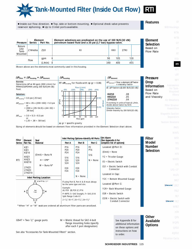
Element Element selections are predicated on the use of 150 SUS (32 cSt) Pressure Series Part No. petroleum based fluid and a 25 psi (1.7 bar) bypass valve.
Z Media Z10 KI KKI 27KI
Flowgpm 0 90 105 120
(L/min) 0 340 400 455
Shown above are the elements most commonly used in this housing.
STAND-ALONE DISPOSABLE ELEMENT
™™
STAND-ALONE DISPOSABLE ELEMENT
™™
115SCHROEDER INDUSTRIES
FilterModelNumberSelection
OtherAvailableOptions
See Appendix B foradditional informationon these options andinstructions on how to order.
PressureDropInformationBased on Flow Rateand Viscosity
ElementSelectionBased on Flow Rate
Features
Tank-Mounted Filter (Inside Out Flow)
Filter Element SealInlet Porting Options–Identify All Ports
Series Part No. Material Port A Port B Port C
KIZ1KIZ3KIZ10
KKIZ1KKIZ3KKIZ10
27KIZ127KIZ327KIZ10
RTI
(Omit) = Buna N
H = EPR*
W = Buna N*
P16P20P24
S16S20S24
F20F24
P16P20P24
S16S20S24
F20F24
N = None
P2P16
S16
N = None
� Inside out flow direction. � Top, side or bottom mounting. � Optional check valve prevents reservoir siphoning. � Up to 3 inlet ports available.
ReturnLine
-Tank-Mounted
RT ∆Phousing for fluids with sp gr = 0.86: ∆Pelement= flow x element ∆P factor x viscosity factor
El. ∆P factors @ 150 SUS (32 cSt):
KIZ10 .08KKIZ10 .0527KIZ10 .04
If working in units of bars & L/min,divide above factor by 54.9.
Viscosity factor:Divide viscosity by 150 SUS (32 cSt).
∆Pfilter = ∆Phousing + ∆Pelement ∆Phousing ∆Pelement
Exercise:Determine ∆P at 80 gpm (300 L/min) forRTIKKIZ10P24NN using 200 SUS (44 cSt)fluid.
Solution:
∆Phousing = 3.0 psi [.20 bar]
∆Pelement = 80 x .05 x (200÷150) = 5.3 psior
∆Pelement = [300 x (.05÷54.9) x (44÷32) = .38 bar]
∆Ptotal = 3.0 + 5.3 = 8.3 psior
∆Pelement = [.20 + .38 = .58 bar]
Sizing of elements should be based on element flow information provided in the Element Selection chart above.
sp gr = specific gravity
(0.25)
(0.50)
(50) (150) (250) (350) (454)10
8
6
4
2
0 0 20 40 60 80 100 120
Flow gpm
Flow (L/min)
∆P (b
ar)
∆P p
si
Located @ Port D:
(Omit) = None
Y2 = Tri-color Gauge
ES = Electric Switch
ES1 = Electric Switch with ConduitConnector
Located in Cap:
Y2C = Bottom Mounted Gauge
Located @ Port C:
Y2R = Back Mounted Gauge
ESR = Electric Switch
ES1R = Electric Switch withConduit Connector
**When “H” or “W” seals are ordered all aluminum filter parts are anodized.
Inlet Porting Location
If using Port B, Port A & B must alwaysbe the same type and size.
Example:(A) P20 (B) P20 (C) P16
P=NPTF, S=SAE Straight, F= SAE J518 Split Flange Code 61
2=1⁄8”, 16=1”, 20=11⁄4”, 24=11⁄2”
G547 = Two 1⁄8” gauge ports M = Metric thread for SAE 4-boltflange mounting holes (specifyafter each F port designation)
See also “Accessories for Tank-Mounted Filters” section.
Dirt Alarm(See Appendix A forcomplete list of options)
RTINEWPRODUCT

FluidCompatibility
Type Fluid Appropriate Schroeder MediaPetroleum Based Fluids All Paper (E) and Synthetic (Z) Media
High Water Content Z1, Z3, Z5, Z10, Z25Invert Emulsions Z10, Z25
Water Glycols Z3, Z5, Z10, Z25Phosphate Esters All Z Media with EPR Seals, K3H and K10H E Media
Skydrol Z3H.5, Z5H.5, Z10H.5, Z25H.5 and WH.5 Note: Contact factory regarding use of E Media in High Water Content, Invert Emulsion and Water Glycol Applications.
For more information, refer toFluid Compatibility:Fire Resistant Fluids,pages 19 and 20.
SCHROEDER INDUSTRIES
Absolute Rating Per ISO 4572/NFPA T3.10.8.8 Abs. Rating wrt ISO 16889 Using automated particle counter (APC) calibrated per ISO 4402 Using APC calibrated per ISO 11171 Dirt Holding
Element ßx ≥ 75 ßx ≥ 100 ßx ≥ 200 ßx(c) ≥ 200 ßx(c) ≥ 1000 Capacity gm
K3 6.8 7.5 10.0 N/A N/A 54
K10 15.5 16.2 18.0 N/A N/A 44
KZ1 <1.0 <1.0 <1.0 <4.0 4.2 112
KZ3 <1.0 <1.0 <2.0 4.7 5.8 115
KZ5 2.5 3.0 4.0 6.5 7.5 86
KZ10 7.4 8.2 10.0 10.0 12.7 108
KZ25 18.0 20.0 22.5 19.0 24.0 93
Element Collapse Rating: 150 psid (10 bar)Flow Direction: Outside In
Element Nominal Dimensions: 4.0” (100 mm) O.D. x 9.0” (230 mm) long
Flow Rating: Up to 100 gpm (380 L/min) for 150 SUS (32 cSt) fluids
Max. Operating Pressure: 100 psi (7 bar)
Min. Yield Pressure: 400 psi (27 bar)
Rated Fatigue Pressure: Contact factory
Temp. Range: -20°F to 225°F (-29°C to 107°C)
Bypass Setting: Cracking: 25 psi (1.7 bar)Full Flow: 48 psi (3.3 bar)
Cap: Die Cast Aluminum (standard), Steel (optional)Element Case: Steel
Weight of KFT-1K: 10.0 lbs. (4.5 kg)Weight of KFT-2K: 13.6 lbs. (6.2 kg)
Element Change Clearance: 8.0” (205 mm)
Filter Housing
Specifications
100 gpm380 L/min
100 psi7 bar
Tank-Mounted Filter
ElementPerformanceInformation
KFT
116
Metric dimensions in ( ).Model No. of filter in photograph is KFT1K10P24P24NBY2.
OU
T
ININ
1.78(45)
(130)
1K =
13.
60 (
345)
2K =
22.
97 (
583)
.12 (3)THICKGASKET
2.59(66)
OPTIONALMOUNTINGRING
OPTIONALCHECK VALVE
5.12
(154)6.06 MAX.
.88(22)
7.00 Ø
(178)
45°
6.82 Ø
(173)
OPTIONALDIRT ALARM ORELECTRIC SWITCH
.44 (11) Ø ON A6.25 (159) Ø B.C.(4) MOUNTING HOLESON OPTIONAL MTG. RING
ST
SKB Housings
MTA
MTB
GT
ZT
RT
RTD
RTI
KFT
LRT
BFT
Accessories for Tank-Mounted
Filters
Air Breathers
Filler StrainerAssemblies
Magnetic SuctionSeparators
Suction Strainers
PAF1
MAF1
MF2
TF1
TF3
KF3
WKF3
LF1
LF1—2"
MLF1
SRLT
SRLT
TRLT
RLT
RLT
WRLT
KF8
QF5
MQF5
QFD2
4QFD2
Filtration Carts
STAND-ALONE DISPOSABLE ELEMENT
™™
STAND-ALONE DISPOSABLE ELEMENT
™™
FilterModelNumberSelection
OtherAvailableOptions
See Appendix B foradditional informationon these options andinstructions on how to order.
PressureDropInformationBased on Flow Rateand Viscosity
ElementSelectionBased on Flow Rate
Features
117SCHROEDER INDUSTRIES
KFTTank-Mounted Filter
G501 = Rubber gasketG820 = Stamped cap
� Meets HF4 automotive standard. � Variety of inlet/outlet porting options. � Top, side or bottom mounting.� Optional check valve prevents reservoir siphoning. � Can also be used in return line application. Contact factory.
KFT ∆Phousing for fluids with sp gr = 0.86:
∆Pfilter = ∆Phousing + ∆Pelement ∆Phousing ∆Pelement
Exercise:Determine ∆P at 80 gpm (300 L/min) forKFT2K10P24 using 200 SUS (44 cSt) fluid.
Solution:
∆Phousing = 3 psi [.25 bar]
∆Pelement = 80 x .05 x (200÷150) = 5.3 psior
∆Pelement = [300 x (.05÷54.9) x (44÷32) = .37 bar]
∆Ptotal = 3.0 + 5.3 = 8.3 psior
∆Pelement = [.25 + .37 = .62 bar]
Sizing of elements should be based on element flow information provided in the Element Selection chart above.
sp gr = specific gravity
(0.25)
(0.50)
(50) (150) (250) (350)10
8
6
4
2
0 0 20 40 60 80 100
Flow gpm
Flow (L/min)
∆P (b
ar)
∆P p
si
Element Element selections are predicated on the use of 150 SUS (32 cSt)Pressure Series Part No. petroleum based fluid and a 25 psi (1.7 bar) bypass valve.
EK3 1K3 2K3
Media K10 1K10 2K10
K25 1K25 2K25
KZ1 1KZ1 2KZ1
KZ3 1KZ3 2KZ3Z KZ5 1KZ5 2KZ5Media
KZ10 1KZ10
KZ25 1KZ25
Flowgpm 0 40 60 80 100
(L/min) 0 50 150 250 380
Shown above are the elements most commonly used in this housing.
ReturnLine
-Tank-Mounted
∆Pelement= flow x element ∆P factor x viscosity factor
El. ∆P factors @ 150 SUS (32 cSt):1K 2K
K3 .25 .12K10 .09 .05K25 .02 .01KZ1 .20 .10KZ3 .10 .05KZ5 .08 .04KZ10 .05 .03KZ25 .04 .02
If working in units of bars & L/min,divide above factor by 54.9.
Viscosity factor:Divide viscosity by 150 SUS (32 cSt).
Filter No. of Element SealInlet Porting Options
Outlet PortingSeries Ele. Part No.† Material Port Size Options
K3K10K25**
KZ1KZ3KZ5KZ10KZ25
KFT1
2
(Omit) = Buna N
H= EPR*
W= Buna N*
—
P24
P20
P16
P12
P8
P4
P2
S24
S20
S16
S12
S8
S4
F24
F32
N
P24
P20
P16
P12
P8
P4
P2
S24
S20
S16
S12
S8
S4
F24
F32
N
P24
P20
P16
P12
P8
P4
P2
S24
S20
S16
S12
S8
S4
N
P24
P20
P16
P12
P8
P4
P2
S24
S20
S16
S12
S8
S4
N = None
1.50 NPTF
1.25 NPTF
1.00 NPTF
0.75 NPTF
0.50 NPTF
0.25 NPTF
0.12 NPTF
1.875-12
1.625-12
1.312-12
1.062-12
0.750-16
0.437-20
1.5 Flange
2.0 Flange
N = Non-Threaded(Omit) = 11⁄2”
NPTMT = 13.00 Non-
Threaded TubeC = Check ValveD = Diffuser
CD= Check Valveand Diffuser
Optional Mounting Flange
(Omit) = NoneB = Flange with
4 HolesBW = Flange with
no Holes
(Omit) = None
Y2 == Back Mounted
Tri-Color Gauge(Port 4) (Not Availablewith 4 Ports)
Y2C == Bottom Mounted
Gauge in Cap
Y5 == Back Mounted
Gauge in Cap
ES == Electric Switch
(Located on FilterHousing—NotAvailable with 4 Ports)
**When “H” or “W” seals are ordered all aluminum filter parts are anodized.**Not available with EPR seals.
†Double and triple stacking of K-size elements can be replaced by single KK and 27K elements, respectively.
Port 1 Port 2 Port 3 Port 4(Std) (Opt) (Opt) (Opt)
See also “Accessories for Tank-Mounted Filters” section.
M = Metric thread for SAE 4-boltflange mounting holes (specifyafter each F port designation)
Dirt Alarm(See Appendix A forcomplete list of options)
FluidCompatibility
Type Fluid Appropriate Schroeder MediaPetroleum Based Fluids All Paper (E) and Synthetic (Z) media
High Water Content Z1, Z3, Z5, Z10, Z25Invert Emulsions Z10, Z25
Water Glycols Z3, Z5, Z10, Z25Phosphate Esters All Z media with EPR Seals
Skydrol Z3H.5, Z5H.5, Z10H.5 and Z25H.5 Note: Contact factory regarding use of E Media in High Water Content, Invert Emulsion and Water Glycol Applications.
For more information, refer toFluid Compatibility:Fire Resistant Fluids,pages 19 and 20.
SCHROEDER INDUSTRIES118
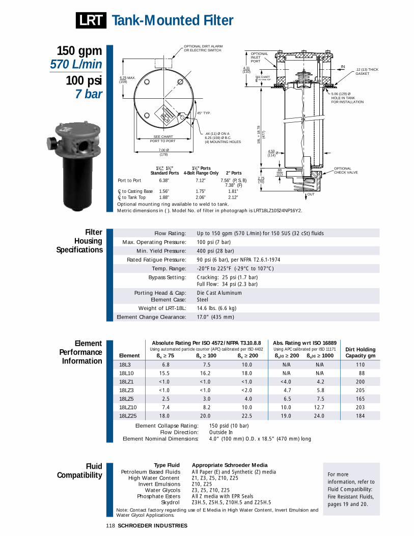
Absolute Rating Per ISO 4572/NFPA T3.10.8.8 Abs. Rating wrt ISO 16889 Using automated particle counter (APC) calibrated per ISO 4402 Using APC calibrated per ISO 11171 Dirt Holding
Element ßx ≥ 75 ßx ≥ 100 ßx ≥ 200 ßx(c) ≥ 200 ßx(c) ≥ 1000 Capacity gm
18L3 6.8 7.5 10.0 N/A N/A 110
18L10 15.5 16.2 18.0 N/A N/A 88
18LZ1 <1.0 <1.0 <1.0 <4.0 4.2 200
18LZ3 <1.0 <1.0 <2.0 4.7 5.8 205
18LZ5 2.5 3.0 4.0 6.5 7.5 165
18LZ10 7.4 8.2 10.0 10.0 12.7 203
18LZ25 18.0 20.0 22.5 19.0 24.0 184
Element Collapse Rating: 150 psid (10 bar)Flow Direction: Outside In
Element Nominal Dimensions: 4.0” (100 mm) O.D. x 18.5” (470 mm) long
Flow Rating: Up to 150 gpm (570 L/min) for 150 SUS (32 cSt) fluids
Max. Operating Pressure: 100 psi (7 bar)
Min. Yield Pressure: 400 psi (28 bar)
Rated Fatigue Pressure: 90 psi (6 bar), per NFPA T2.6.1-1974
Temp. Range: -20°F to 225°F (-29°C to 107°C)
Bypass Setting: Cracking: 25 psi (1.7 bar)Full Flow: 34 psi (2.3 bar)
Porting Head & Cap: Die Cast AluminumElement Case: Steel
Weight of LRT-18L: 14.6 lbs. (6.6 kg)
Element Change Clearance: 17.0” (435 mm)
Filter Housing
Specifications
150 gpm570 L/min
100 psi7 bar
Tank-Mounted Filter
ElementPerformanceInformation
LRT
Metric dimensions in ( ). Model No. of filter in photograph is LRT18LZ10S24NP16Y2.
(114)
5.06 (129) ØHOLE IN TANK
4.50
(22).88
18L
= 1
8.78
4.31 IN(110)
(477
)
.44 (11) Ø ON A6.25 (159) Ø B.C.(4) MOUNTING HOLES
OPTIONAL DIRT ALARMOR ELECTRIC SWITCH
OPTIONALCHECK VALVE
OUT
(70)2.75
OPTIONALINLETPORT
FOR INSTALLATION
Ø
.12 (13) THICKGASKET
SEE CHARTPORT TO PORT
7.00 Ø(178)
6.25(159)
MAX.CSEE CHART
TO TANK TOP
45° TYP.
Optional mounting ring available to weld to tank.
11⁄4”, 11⁄2” 11⁄2” PortsStandard Ports 4-Bolt Flange Only 2” Ports
Port to Port 6.38” 7.12” 7.56” (P, S, B)7.38” (F)
CL to Casting Base 1.56” 1.75” 1.81”CL to Tank Top 1.88” 2.06” 2.12”
ST
SKB Housings
MTA
MTB
GT
ZT
RT
RTD
RTI
KFT
LRT
BFT
Accessories for Tank-Mounted
Filters
Air Breathers
Filler StrainerAssemblies
Magnetic SuctionSeparators
Suction Strainers
PAF1
MAF1
MF2
TF1
TF3
KF3
WKF3
LF1
LF1—2"
MLF1
SRLT
SRLT
TRLT
RLT
RLT
WRLT
KF8
QF5
MQF5
QFD2
4QFD2
Filtration Carts
STAND-ALONE DISPOSABLE ELEMENT
™™
STAND-ALONE DISPOSABLE ELEMENT
™™
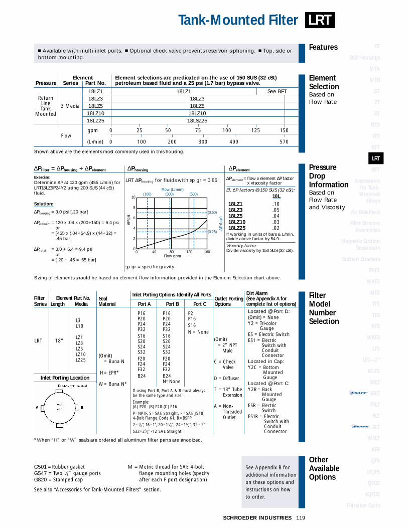
Element Element selections are predicated on the use of 150 SUS (32 cSt)Pressure Series Part No. petroleum based fluid and a 25 psi (1.7 bar) bypass valve.
18LZ1 18LZ1 See BFT
Z Media18LZ3 18LZ318LZ5 18LZ518LZ10 18LZ1018LZ25 18LSZ25
Flowgpm 0 25 50 75 100 125 150
(L/min) 0 100 200 300 400 570
Shown above are the elements most commonly used in this housing.
FilterModelNumberSelection
OtherAvailableOptions
See Appendix B foradditional informationon these options andinstructions on how to order.
PressureDropInformationBased on Flow Rateand Viscosity
ElementSelectionBased on Flow Rate
Features
119SCHROEDER INDUSTRIES
LRTTank-Mounted Filter
� Available with multi inlet ports. � Optional check valve prevents reservoir siphoning. � Top, side orbottom mounting.
∆Pfilter = ∆Phousing + ∆Pelement ∆Phousing ∆Pelement
Exercise:Determine ∆P at 120 gpm (455 L/min) forLRT18LZ5P24Y2 using 200 SUS (44 cSt)fluid.
Solution:
∆Phousing = 3.0 psi [.20 bar]
∆Pelement = 120 x .04 x (200÷150) = 6.4 psior
∆Pelement = [455 x (.04÷54.9) x (44÷32) = .45 bar]
∆Ptotal = 3.0 + 6.4 = 9.4 psior
∆Pelement = [.20 + .45 = .65 bar]
∆Pelement= flow x element ∆P factor x viscosity factor
El. ∆P factors @ 150 SUS (32 cSt):18L
18LZ1 .1018LZ3 .0518LZ5 .0418LZ10 .0318LZ25 .02
If working in units of bars & L/min,divide above factor by 54.9.
Viscosity factor:Divide viscosity by 150 SUS (32 cSt).
Sizing of elements should be based on element flow information provided in the Element Selection chart above.
LRT ∆Phousing for fluids with sp gr = 0.86:
sp gr = specific gravity
(0.25)
(0.50)
(100) (300) (500)10
8
6
4
2
0 0 40 80 120 160
Flow gpm
Flow (L/min)
∆P (b
ar)
∆P p
si
ReturnLine
-Tank-Mounted
L3L10
LZ1LZ3LZ5LZ10LZ25
LRT 18”
(Omit) = Buna N
H= EPR*
W= Buna N*
P16P20P24P32S16S20S24S32F20F24F32B24
P16P20P24P32S16S20S24S32F20F24F32B24N=None
P2P16S16N = None
(Omit)= 2” NPT
Male
C = CheckValve
D = Diffuser
T = 13” TubeExtension
A = Non-ThreadedOutlet
Located @ Port D:(Omit) = NoneY2 = Tri-color
GaugeES = Electric SwitchES1 = Electric
Switch withConduitConnector
Located in Cap:Y2C = Bottom
MountedGauge
Located @ Port C:Y2R = Back
MountedGauge
ESR = ElectricSwitch
ES1R = ElectricSwitch withConduitConnector
*When “H” or “W” seals are ordered all aluminum filter parts are anodized.
Inlet Porting Location
G501 = Rubber gasketG547 = Two 1⁄8” gauge portsG820 = Stamped cap
M = Metric thread for SAE 4-boltflange mounting holes (specifyafter each F port designation)
See also “Accessories for Tank-Mounted Filters” section.
Filter Element Part No. SealInlet Porting Options–Identify All Ports
Outlet PortingSeries Length Media Material Port A Port B Port C Options
Dirt Alarm(See Appendix A forcomplete list of options)
If using Port B, Port A & B must alwaysbe the same type and size.
Example:(A) P20 (B) P20 (C) P16
P=NPTF, S=SAE Straight, F= SAE J518 4-Bolt Flange Code 61, B=BSPP
2=1⁄8”, 16=1”, 20=11⁄4”, 24=11⁄2”, 32=2”
S32=21⁄2”-12 SAE Straight
FluidCompatibility
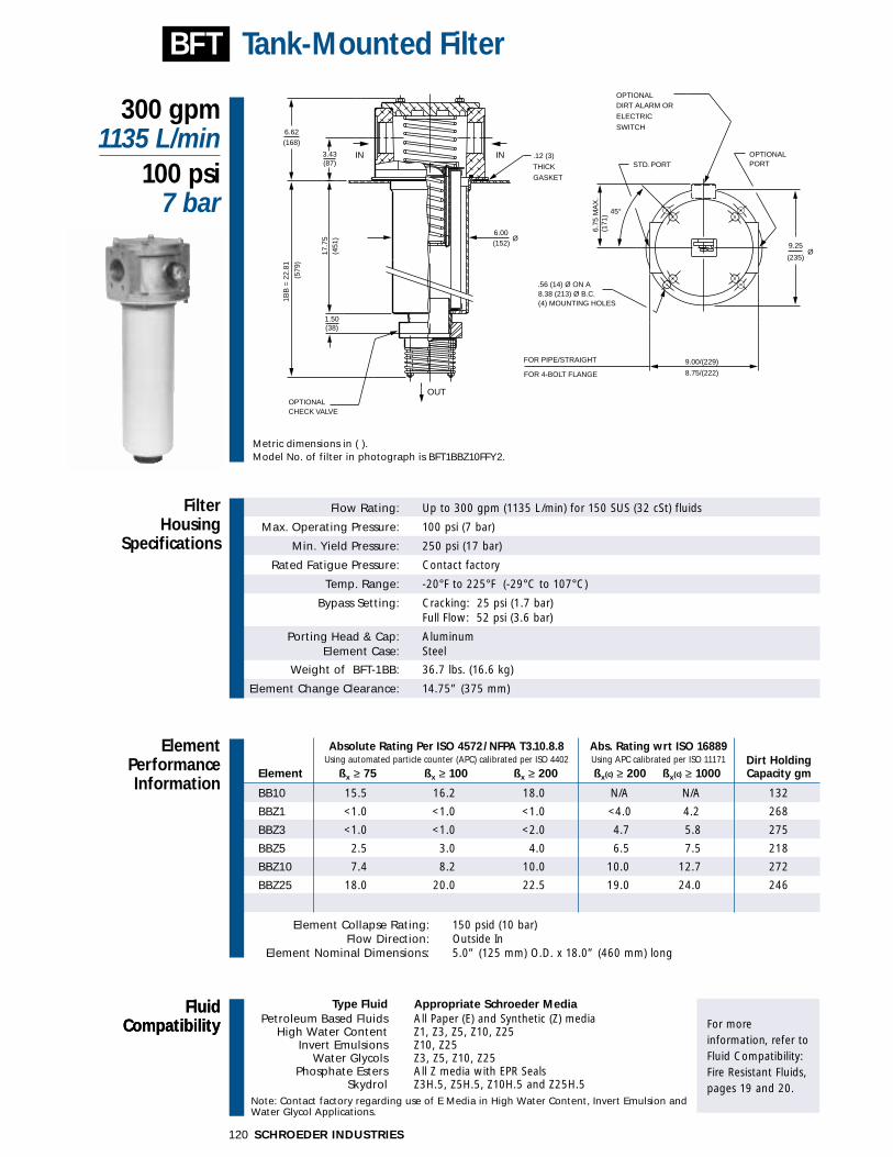
Type Fluid Appropriate Schroeder MediaPetroleum Based Fluids All Paper (E) and Synthetic (Z) media
High Water Content Z1, Z3, Z5, Z10, Z25Invert Emulsions Z10, Z25
Water Glycols Z3, Z5, Z10, Z25Phosphate Esters All Z media with EPR Seals
Skydrol Z3H.5, Z5H.5, Z10H.5 and Z25H.5 Note: Contact factory regarding use of E Media in High Water Content, Invert Emulsion and Water Glycol Applications.
For more information, refer toFluid Compatibility:Fire Resistant Fluids,pages 19 and 20.
Absolute Rating Per ISO 4572/NFPA T3.10.8.8 Abs. Rating wrt ISO 16889 Using automated particle counter (APC) calibrated per ISO 4402 Using APC calibrated per ISO 11171 Dirt Holding
Element ßx ≥ 75 ßx ≥ 100 ßx ≥ 200 ßx(c) ≥ 200 ßx(c) ≥ 1000 Capacity gm
BB10 15.5 16.2 18.0 N/A N/A 132
BBZ1 <1.0 <1.0 <1.0 <4.0 4.2 268
BBZ3 <1.0 <1.0 <2.0 4.7 5.8 275
BBZ5 2.5 3.0 4.0 6.5 7.5 218
BBZ10 7.4 8.2 10.0 10.0 12.7 272
BBZ25 18.0 20.0 22.5 19.0 24.0 246
Element Collapse Rating: 150 psid (10 bar)Flow Direction: Outside In
Element Nominal Dimensions: 5.0” (125 mm) O.D. x 18.0” (460 mm) long
Flow Rating: Up to 300 gpm (1135 L/min) for 150 SUS (32 cSt) fluids
Max. Operating Pressure: 100 psi (7 bar)
Min. Yield Pressure: 250 psi (17 bar)
Rated Fatigue Pressure: Contact factory
Temp. Range: -20°F to 225°F (-29°C to 107°C)
Bypass Setting: Cracking: 25 psi (1.7 bar)Full Flow: 52 psi (3.6 bar)
Porting Head & Cap: AluminumElement Case: Steel
Weight of BFT-1BB: 36.7 lbs. (16.6 kg)
Element Change Clearance: 14.75” (375 mm)
Filter Housing
Specifications
300 gpm1135 L/min
100 psi7 bar
Tank-Mounted Filter
ElementPerformanceInformation
BFT
FluidCompatibility
Metric dimensions in ( ).Model No. of filter in photograph is BFT1BBZ10FFY2.
IN IN3.43(87)
(168)
17.7
5(4
51)
(579
)
(152)
.12 (3)
THICK
GASKET
CHECK VALVEOPTIONAL
6.00
45°
STD. PORT
DIRT ALARM OR
ELECTRIC
SWITCH
(235)
9.25
OPTIONALPORT
8.75/(222)
.56 (14) Ø ON A8.38 (213) Ø B.C.(4) MOUNTING HOLES
OUT
9.00/(229)FOR PIPE/STRAIGHT
FOR 4-BOLT FLANGE
OPTIONAL
1BB
= 2
2.81
Ø
Ø
6.62
6.75
MA
X.
(171
)
1.50(38)
SCHROEDER INDUSTRIES120

ST
SKB Housings
MTA
MTB
GT
ZT
RT
RTD
RTI
KFT
LRT
BFT
Accessories for Tank-Mounted
Filters
Air Breathers
Filler StrainerAssemblies
Magnetic SuctionSeparators
Suction Strainers
PAF1
MAF1
MF2
TF1
TF3
KF3
WKF3
LF1
LF1—2"
MLF1
SRLT
SRLT
TRLT
RLT
RLT
WRLT
KF8
QF5
MQF5
QFD2
4QFD2
Filtration Carts
STAND-ALONE DISPOSABLE ELEMENT
™™
STAND-ALONE DISPOSABLE ELEMENT
™™
121SCHROEDER INDUSTRIES
FilterModelNumberSelection
OtherAvailableOptions
See Appendix B foradditional informationon these options andinstructions on how to order.
PressureDropInformationBased on Flow Rateand Viscosity
ElementSelectionBased on Flow Rate
Features
BFTTank-Mounted Filter
BB10**BB25**
BBZ1BBZ3BBZ5BBZ10BBZ25
BFT 1
(Omit) = Buna N
H = EPR*
W = Buna N*
P = 21⁄2” NPTF
PP = Dual 21⁄2” NPTF
S = 21⁄2”-12 SAEStraight(SAE-32)
SS = Dual 21⁄2”-12SAE Straight(SAE-32)
F = 21⁄2” SAE J5184-Bolt FlangeCode 61
FF = Dual 21⁄2” SAEJ518 4-BoltFlange Code 61
G547 = Two 1⁄8” gauge portsG1476 = Three terminal electric
switch
Element Element selections are predicated on the use of 150 SUS (32 cSt) petroleumPressure Series Part No. based fluid and a 25 psi (1.7 bar) bypass valve (with check valve option).
E BB10 1BB10 See MLFMedia BB25 1BB25
BBZ1 *BBZ1*
ZBBZ3 *BBZ3*
Media BBZ5 BBZ5BBZ10 BBZ10BBZ25 BBZ25
Flow gpm 0 100 150 200 250 300
(L/min) 0 400 600 800 1000 1150
Shown above are the elements most commonly used in this housing.*Note: Additional per element flow is available up to 300 gpm when using BFT filter without check valve option. See
housing pressure drop graph below.
� Dual inlet porting. � Top, side or bottom mounting. � Optional check valve prevents reservoirsiphoning.
ReturnLine
-Tank-Mounted
BFT ∆Phousing for fluids with sp gr = 0.86: ∆Pelement= flow x element ∆P factor x viscosity factor
El. ∆P factors @ 150 SUS (32 cSt):BB
BB10 .03BB25 .01BBZ1 .07BBZ3 .05BBZ5 .04BBZ10 .03BBZ25 .02
If working in units of bars & L/min,divide above factor by 54.9.
Viscosity factor:Divide viscosity by 150 SUS (32 cSt).
∆Pfilter = ∆Phousing + ∆Pelement ∆Phousing ∆Pelement
Exercise:Determine ∆P at 160 gpm (600 L/min) forBFT1BBZ3PCY2 using 200 SUS (44 cSt)fluid.
Solution:
∆Phousing = 2.5 psi [.20 bar]
∆Pelement = 160 x .05 x (200÷150) = 10.7 psior
∆Pelement = [600 x (.05÷54.9) x (44÷32) = .8 bar]
∆Ptotal = 2.5 + 10.7 = 13.2 psior
∆Pelement = [.20 + .8 = 1.0 bar]
Sizing of elements should be based on element flow information provided in the Element Selection chart above.
sp gr = specific gravity
(1000)(400) (600) (800)10
8
6
4
2
0 100 150 200 250 300
Flow gpm
Flow (L/min)
∆P (b
ar)
∆P p
si
(0.25)
(0.50)
W/ CHECK VALVE
W/O CHECK VALVE
Y2= Tri-ColorGauge
ES= ElectricSwitch
ES1= Heavy-DutyElectricSwitch withConduitConnection
**When H or W seals are ordered, all aluminum filter parts are anodized.**Only available with Buna N seals.
Filter No. of Element Seal Outlet OptionalSeries Ele. Part No. Material Porting Porting Check Valve
(Omit) = None
C = CheckValve
See also “Accessories for Tank-Mounted Filters” section.
(Omit) = 3” NPT
Male
T = 13" TubeExtension
M = Metric thread for SAE 4-boltflange mounting holes (specifyafter each F port designation)
Dirt Alarm(See Appendix A forcomplete list of options)
SCHROEDER INDUSTRIES122
Diffuser for RT,RTD, LRT, and
KFT Models
Accessories for Tank-Mounted Filters
B
A
GASKET
MOUNTINGRING WELDED
C
TO TANK
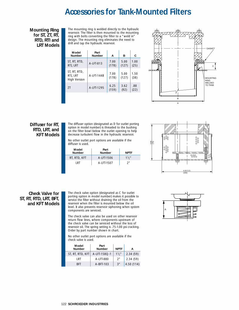
Mounting Ring for ST, ZT, RT, RTD, RTI and LRT Models
Model Part Number Number A B C
ST, RT, RTD,A-LFT-813
7.00 5.00 1.00 RTI, LRT (178) (127) (25)
ST, RT, RTD, RTI, LRT A-LFT-1448
7.00 5.00 1.50
High Version (178) (127) (38)
ZT A-LFT-12956.25 3.62 .88(159) (92) (22)
Model Part Number Number NPTF A
ST, RT, RTD, KFT A-LFT-158Q-1 11⁄2” 2.34 (59)
LRT A-LFT-880 2” 2.34 (59)
BFT A-BFT-103 3” 4.50 (114)
The mounting ring is welded directly to the hydraulicreservoir. The filter is then mounted to the mountingring with bolts converting the filter to a “weld in”design. The mounting ring eliminates the need todrill and tap the hydraulic reservoir.
The diffuser option (designated as D for outlet portingoption in model number) is threaded to the bushingon the filter bowl below the outlet opening to helpdecrease turbulent flow in the hydraulic reservoir.
No other outlet port options are available if the diffuser is used.
Check Valve for ST, RT, RTD, LRT, BFT,
and KFT Models
The check valve option (designated as C for outletporting option in model number) makes it possible toservice the filter without draining the oil from thereservoir when the filter is mounted below the oillevel. It also prevents reservoir siphoning when systemcomponents are serviced.
The check valve can also be used on other reservoirreturn flow lines, where components upstream of the check valve can be serviced without the loss ofreservoir oil. The spring setting is .75-1.00 psi cracking.Order by part number shown in chart.
No other outlet port options are available if the check valve is used.
4.00 O.D.(102)
3.00
(76)
A
Model Part Number Number NPTF
RT, RTD, KFT A-LFT-1506 11⁄2”
LRT A-LFT-1507 2”
ST
SKB Housings
MTA
MTB
GT
ZT
RT
RTD
RTI
KFT
LRT
BFT
Accessories for Tank-Mounted
Filters
Air Breathers
Filler StrainerAssemblies
Magnetic SuctionSeparators
Suction Strainers
PAF1
MAF1
MF2
TF1
TF3
KF3
WKF3
LF1
LF1—2"
MLF1
SRLT
SRLT
TRLT
RLT
RLT
WRLT
KF8
QF5
MQF5
QFD2
4QFD2
Filtration Carts
STAND-ALONE DISPOSABLE ELEMENT
™™
STAND-ALONE DISPOSABLE ELEMENT
™™
ThreadedOutlet Port for ZT, RT, RTD,LRT, BFT, and KFTModels
TubeAdapterOutlet Port for RT,RTD, KFT,LRT andBFTModels
Check ValveDiffuserCombinationfor RT, RTDand KFTModels
123SCHROEDER INDUSTRIES
Accessories for Tank-Mounted Filters
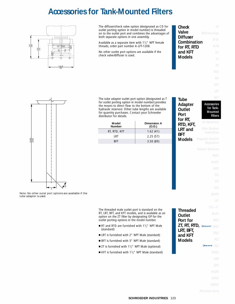
The diffuser/check valve option (designated as CD foroutlet porting option in model number) is threadedon to the outlet port and combines the advantages ofboth separate options in one assembly.
Available as a separate item with 11⁄2” NPT femalethreads, order part number A-LFT-1208.
No other outlet port options are available if the check valve/diffuser is used.
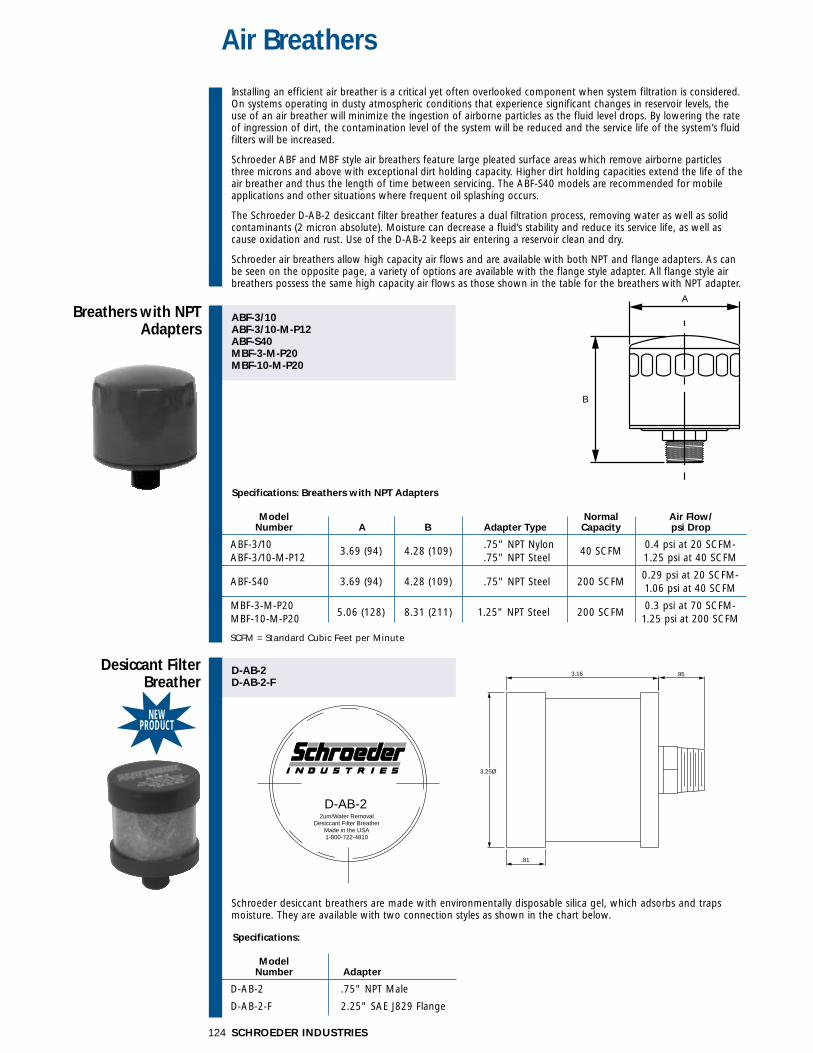
The tube adapter outlet port option (designated as Tfor outlet porting option in model number) providesthe means to direct flow to the bottom of thehydraulic reservoir. Other tube lengths are availablefor quantity purchases. Contact your Schroeder distributor for details.
The threaded male outlet port is standard on the RT, LRT, BFT, and KFT models, and is available as anoption on the ZT filter by designating OP for theoutlet porting options in the model number.
� RT and RTD are furnished with 11⁄2” NPT Male(standard)
� LRT is furnished with 2” NPT Male (standard)
� BFT is furnished with 3” NPT Male (standard)
� ZT is furnished with 11⁄2” NPT Male (optional)
� KFT is furnished with 11⁄2” NPT Male (standard)
2.94
(75)
3.50
(89)
3.90 Ø(99)
13.0
0(3
30)
A
45°
Note: No other outet port options are available if thetube adapter is used.
Model Dimension A Number (O.D.)
RT, RTD, KFT 1.62 (41)
LRT 2.25 (57)
BFT 3.50 (89)
Specifications: Breathers with NPT Adapters
Model Normal Air Flow/Number A B Adapter Type Capacity psi Drop
ABF-3/10 .75" NPT Nylon 0.4 psi at 20 SCFM-ABF-3/10-M-P12
3.69 (94) 4.28 (109).75" NPT Steel
40 SCFM1.25 psi at 40 SCFM
200 SCFM0.29 psi at 20 SCFM-
ABF-S40 3.69 (94) 4.28 (109) .75" NPT Steel1.06 psi at 40 SCFM
MBF-3-M-P20200 SCFM
0.3 psi at 70 SCFM-MBF-10-M-P20
5.06 (128) 8.31 (211) 1.25" NPT Steel1.25 psi at 200 SCFM
SCFM = Standard Cubic Feet per Minute
SCHROEDER INDUSTRIES124
Air Breathers
Specifications:
Model Number Adapter
D-AB-2 .75" NPT Male
D-AB-2-F 2.25" SAE J829 Flange
Breathers with NPTAdapters
ABF-3/10ABF-3/10-M-P12ABF-S40MBF-3-M-P20MBF-10-M-P20
D-AB-2D-AB-2-F
A
B
Desiccant FilterBreather
Installing an efficient air breather is a critical yet often overlooked component when system filtration is considered.On systems operating in dusty atmospheric conditions that experience significant changes in reservoir levels, theuse of an air breather will minimize the ingestion of airborne particles as the fluid level drops. By lowering the rateof ingression of dirt, the contamination level of the system will be reduced and the service life of the system’s fluidfilters will be increased.
Schroeder ABF and MBF style air breathers feature large pleated surface areas which remove airborne particlesthree microns and above with exceptional dirt holding capacity. Higher dirt holding capacities extend the life of theair breather and thus the length of time between servicing. The ABF-S40 models are recommended for mobileapplications and other situations where frequent oil splashing occurs.
The Schroeder D-AB-2 desiccant filter breather features a dual filtration process, removing water as well as solidcontaminants (2 micron absolute). Moisture can decrease a fluid’s stability and reduce its service life, as well ascause oxidation and rust. Use of the D-AB-2 keeps air entering a reservoir clean and dry.
Schroeder air breathers allow high capacity air flows and are available with both NPT and flange adapters. As canbe seen on the opposite page, a variety of options are available with the flange style adapter. All flange style airbreathers possess the same high capacity air flows as those shown in the table for the breathers with NPT adapter.
Schroeder desiccant breathers are made with environmentally disposable silica gel, which adsorbs and trapsmoisture. They are available with two connection styles as shown in the chart below.
NEWPRODUCT
3.16
3.25Ø
.95
.81
2um/Water RemovalDesiccant Filter Breather
Made in the USA1-800-722-4810
D-AB-2
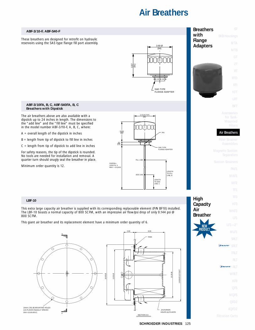
ST
SKB Housings
MTA
MTB
GT
ZT
RT
RTD
RTI
KFT
LRT
BFT
Accessories for Tank-Mounted
Filters
Air Breathers
Filler StrainerAssemblies
Magnetic SuctionSeparators
Suction Strainers
PAF1
MAF1
MF2
TF1
TF3
KF3
WKF3
LF1
LF1—2"
MLF1
SRLT
SRLT
TRLT
RLT
RLT
WRLT
KF8
QF5
MQF5
QFD2
4QFD2
Filtration Carts
STAND-ALONE DISPOSABLE ELEMENT
™™
STAND-ALONE DISPOSABLE ELEMENT
™™
ABF-3/10FA, B, C, ABF-S40FA, B, CBreathers with Dipstick
125SCHROEDER INDUSTRIES
Air Breathers
ABF-3/10-F, ABF-S40-F
SAE-TYPEFLANGE ADAPTER
3.57
(91)
3.69 Ø(94)
These breathers are designed for retrofit on hydraulicreservoirs using the SAE-type flange fill port assembly.
The air breathers above are also available with adipstick up to 24 inches in length. The dimensions tothe “add line” and the “fill line” must be specifiedin the model number ABF-3/10-F, A, B, C, where:
A = overall length of the dipstick in inches
B = length from tip of dipstick to fill line in inches
C = length from tip of dipstick to add line in inches
For safety reasons, the tip of the dipstick is rounded.No tools are needed for installation and removal. Aquarter turn should snugly seal the breather in place.
Minimum order quantity is 12.
3.531(90)
SAE-TYPEFLANGE ADAPTER
3.75 Ø (TYP)(95)
.53
OVERALLLENGTH, AMAX. = 24 (610)
LENGTHTO ADDLINE, C
LENGTHTO FILLLINE, B
PIN
FILL LINE
ADD LINE
(13)
Breathers withFlange Adapters
LBF-10
This extra large capacity air breather is supplied with its corresponding replaceable element (P/N BF10) installed.The LBF-10 boasts a normal capacity of 800 SCFM, with an impressive air flow/psi drop of only 0.144 psi @ 800 SCFM.
This giant air breather and its replacement element have a minimum order quantity of 6.
HighCapacityAirBreather
NEWPRODUCT
12.2
5 Ø
14.0
0 Ø
CU
T-O
UT
16.0
0 Ø
3.00
13.5
0 Ø
A
SECTION A-A
TANK
8.00
A
14mm (.551 Ø) MOUNTING HOLES(12) PLACES EQUALLY SPACED .25 Ø DRAIN
HOLES (4) PLACESON A 15.00 Ø B.C.

Filler Strainer Assemblies
Filler Breatherwith Strainer
ABF-3/10-SABF-3/10-S6 ABF-S40-6ABF-S40-S6
A-TB-779 A-TB-780
MOUNTING REQUIREMENT
2.12 (54) DIA. HOLE
#26 DRILL (6 HOLES)ON A 2.88 (73) B.C.
STRAINER
4.48(114)
-S6 = 6.00 (152)
-S = 3.71 (94)
3.69 Ø(94)
The strainer used here is #24 mesh and is available in the lengths shown.
Rapid Fill Cap and Strainer
Speed the process of adding fluid to a reservoir byusing our rapid fill cap and strainer. The strainer is4.38” in diameter and designed to accept cold viscousfluids easily. Choose from two strainer mesh sizes:A-TB-779, which features #24 mesh, and A-TB-780,which is supplied with #70 mesh. The cap completelyseals the opening. All assemblies are supplied withnecessary hardware, including retaining chain for capand self tapping screws for installation.
Specifications: A-TB’s
Model Mesh Strainer Strainer FlangeNumber Size O.D. Height Diameter
A-TB-780 70 4.38 3.94 5.56
A-TB-779 24 (111) (100) (141)
Metric dimensions in ( ).RESERVOIR
4.38 Ø
4.41 Ø(112)
RETAINING CHAIN
CAP
#26 DRILL ON A 4.50 (114) RADIUS(IN TANK LID)
#26 DRILL (6) HOLES ON A 4.94 (125) B.C.(IN TANK LID)
3.94(100) 4.50 (114) DIA. HOLE
REQUIRED FOR INSTALLATION(IN TANK LID)
GASKET
1.31(33)
SCHROEDER INDUSTRIES126
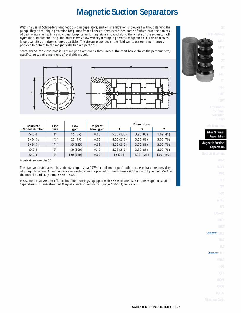
127SCHROEDER INDUSTRIES
Magnetic Suction Separators
With the use of Schroeder’s Magnetic Suction Separators, suction line filtration is provided without starving thepump. They offer unique protection for pumps from all sizes of ferrous particles, some of which have the potentialof destroying a pump in a single pass. Large ceramic magnets are spaced along the length of the separator. Allhydraulic fluid entering the pump must move at low velocity through a powerful magnetic field. This field trapslarge quantities of micronic ferrous particles. The viscous properties of the fluid can cause some non-ferrous particles to adhere to the magnetically trapped particles.
Schroeder SKB’s are available in sizes ranging from one to three inches. The chart below shows the part numbers,specifications, and dimensions of available models.
The standard outer screen has adequate open area (.079 inch diameter perforations) to eliminate the possibilityof pump starvation. All models are also available with a pleated 20 mesh screen (850 micron) by adding SS20 tothe model number. (Example SKB-1-SS20.)
Please note that we also offer in-line filter housings equipped with SKB elements. See In-Line Magnetic SuctionSeparators and Tank-Mounted Magnetic Suction Separators (pages 100-101) for details.
AC
B
Complete Pipe Flow ∆ psi at Dimensions
Model Number Size gpm Max. gpm A B C
SKB-1 1” 15 (55) 0.05 5.25 (133) 3.25 (83) 1.62 (41)
SKB-11⁄4 11⁄4” 25 (95) 0.05 8.25 (210) 3.50 (89) 3.00 (76)
SKB-11⁄2 11⁄2” 35 (135) 0.08 8.25 (210) 3.50 (89) 3.00 (76)
SKB-2 2” 50 (190) 0.10 8.25 (210) 3.50 (89) 3.00 (76)
SKB-3 3” 100 (380) 0.02 10 (254) 4.75 (121) 4.00 (102)
Metric dimensions in ( ).
ST
SKB Housings
MTA
MTB
GT
ZT
RT
RTD
RTI
KFT
LRT
BFT
Accessories for Tank-Mounted
Filters
Air Breathers
Filler StrainerAssemblies
Magnetic SuctionSeparators
Suction Strainers
PAF1
MAF1
MF2
TF1
TF3
KF3
WKF3
LF1
LF1—2"
MLF1
SRLT
SRLT
TRLT
RLT
RLT
WRLT
KF8
QF5
MQF5
QFD2
4QFD2
Filtration Carts
STAND-ALONE DISPOSABLE ELEMENT
™™
STAND-ALONE DISPOSABLE ELEMENT
™™

SCHROEDER INDUSTRIES128
Suction Strainers
C
B
NPTTHREAD
A
These all metal suction strainers are furnished with optimizedpleat size and screen area for extended life and low pressuredrop. 100 mesh stainless steel screen (140 micron) has 33.3%open area. Porting head is carbon steel, center core is platedperforated steel. End cap is heavy gauge zinc plated steel.These strainers can handle temperatures up to 250°F (121°C).
60 mesh (238 micron) and 200 mesh (74 micron) models alsoavailable — contact factory.
Our externally mounted suction strainers (ESS) are functionallyequivalent to our standard strainers with the added feature ofbeing installed through the wall of the reservoir. They areavailable with an optional 3 psi bypass valve.
Model Number Other Information
Optional Dimensions ScreenBasic 3 psi Pipe Flow* Area
Model Bypass Size gpm (L/min) A B C in2 (cm2)
SS-1⁄2-100 (Omit) =1⁄2” 5 (19) 3.10 (79) 2.63 (67) 1.12 (28) 62 (400)
SS-3⁄4-100 None 3⁄4” 8 (30) 3.55 (90) 2.63 (67) 1.31 (33) 88 (567)
SS-1-100 1” 10 (38) 5.35 (136) 2.63 (67) 1.62 (41) 110 (710)
SS-11⁄4-100 -3 = 11⁄4” 20 (76) 6.85 (174) 3.38 (89) 1.88 (48) 162 (1045)
SS-11⁄2-100 Bypass 11⁄2” 30 (114) 8.01 (204) 3.38 (89) 2.12 (54) 225 (1450)
SS-2-100 valve 2” 50 (189) 9.85 (250) 3.94 (100) 2.75 (70) 340 (2200)
SS-21⁄2-100 21⁄2” 75 (284) 10.10 (257) 5.12 (130) 3.50 (89) 400 (2580)
SS-3-100 3” 100 (379) 11.78 (299) 5.12 (130)4.00 (102)
500 (3225)Round
TO PUMP
RESERVOIR
*Flow rating based on 5 FPS or less.
Metric dimensions in ( ).Examples: SS-2-100 SS suction strainer, 2” NPT, without bypass valve.
SS-1-100-3 SS suction strainer, 1” NPT, with 3 psi bypass valve.

ST
SKB Housings
MTA
MTB
GT
ZT
RT
RTD
RTI
KFT
LRT
BFT
Accessories for Tank-Mounted
Filters
Air Breathers
Filler StrainerAssemblies
Magnetic SuctionSeparators
Suction Strainers
PAF1
MAF1
MF2
TF1
TF3
KF3
WKF3
LF1
LF1—2"
MLF1
SRLT
SRLT
TRLT
RLT
RLT
WRLT
KF8
QF5
MQF5
QFD2
4QFD2
Filtration Carts
STAND-ALONE DISPOSABLE ELEMENT
™™
STAND-ALONE DISPOSABLE ELEMENT
™™
129SCHROEDER INDUSTRIES
Suction Strainers
Model Number
Optional Flow A B C D E F ScreenBasic 3 psi Rating External Internal Overall Bushing End Cap Hex Area
Model Bypass gpm (L/min) Thread Thread Length Length O.D. Size in2 (cm2)
ESS-10P (Omit) = 10 (38) 11⁄4" NPT 3⁄4" NPT 8.18 (208) 1.20 (30) 1.38 (35) 1.75 (44) 64 (413)
ESS-15P None 15 (57) 11⁄2" NPT 1" NPT 8.25 (210) 1.23 (31) 1.66 (42) 2.00 (51) 87 (561)
ESS-25P 25 (95) 2" NPT 11⁄4" NPT 9.03 (229) 1.33 (34) 2.12 (54) 2.50 (64) 125 (806)
ESS-50P -3 = 50 (189) 3" NPT 2" NPT 9.70 (246) 1.68 (43) 3.00 (76) 3.25 (83) 260 (1677)
ESS-100P Bypass 100 (379) 4" NPT 3" NPT 11.31 (287) 1.75 (44) 3.94 (100) 4.62 (117) 315 (2032)
ESS-10S valve 10 (38) 15⁄8"-12 SAE 15⁄16"-12 SAE 8.00 (203) 1.19 (30) 1.38 (35) 1.88 (48) 64 (413)
ESS-15S 15 (57) 17⁄8"-12 SAE 15⁄8"-12 SAE 8.38 (213) 1.60 (41) 1.66 (42) 2.12 (54) 87 (561)
ESS-25S 25 (95) 21⁄2"-12 SAE 17⁄8"-12 SAE 8.90 (226) 1.50 (38) 2.12 (54) 2.75 (70) 125 (806)
Metric dimensions in ( ). .
(C)
(D)
(B)
(A)
(F)
(E)
BUSHING
INTERNALTHREAD
EXTERNAL THREAD
OVERALL LENGTHWIDTH ACROSS FLATS
EN
D C
AP
O.D
.
BYPASS VALVEOPTIONAL 3 PSI
T
OC
I N
SRH
UD S
E
EE
R ID
S
R
NEWPRODUCT
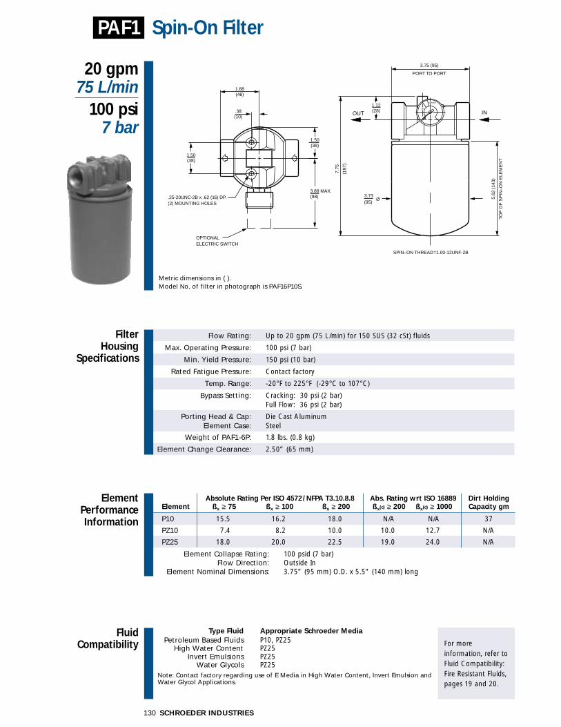
FluidCompatibility
Type Fluid Appropriate Schroeder MediaPetroleum Based Fluids P10, PZ25
High Water Content PZ25Invert Emulsions PZ25
Water Glycols PZ25Note: Contact factory regarding use of E Media in High Water Content, Invert Emulsion and Water Glycol Applications.
For more information, refer toFluid Compatibility:Fire Resistant Fluids,pages 19 and 20.
SCHROEDER INDUSTRIES130
Absolute Rating Per ISO 4572/NFPA T3.10.8.8 Abs. Rating wrt ISO 16889 Dirt Holding Element ßx ≥ 75 ßx ≥ 100 ßx ≥ 200 ßx(c) ≥ 200 ßx(c) ≥ 1000 Capacity gm
P10 15.5 16.2 18.0 N/A N/A 37
PZ10 7.4 8.2 10.0 10.0 12.7 N/A
PZ25 18.0 20.0 22.5 19.0 24.0 N/A
Element Collapse Rating: 100 psid (7 bar)Flow Direction: Outside In
Element Nominal Dimensions: 3.75” (95 mm) O.D. x 5.5” (140 mm) long
Flow Rating: Up to 20 gpm (75 L/min) for 150 SUS (32 cSt) fluids
Max. Operating Pressure: 100 psi (7 bar)
Min. Yield Pressure: 150 psi (10 bar)
Rated Fatigue Pressure: Contact factory
Temp. Range: -20°F to 225°F (-29°C to 107°C)
Bypass Setting: Cracking: 30 psi (2 bar)Full Flow: 36 psi (2 bar)
Porting Head & Cap: Die Cast AluminumElement Case: Steel
Weight of PAF1-6P: 1.8 lbs. (0.8 kg)
Element Change Clearance: 2.50” (65 mm)
Filter Housing
Specifications
20 gpm75 L/min
100 psi7 bar
Spin-On Filter
ElementPerformanceInformation
PAF1
Metric dimensions in ( ).Model No. of filter in photograph is PAF16P10S.
3.88 MAX.(98)
PORT TO PORT
3.75 (95)
3.73(95)
Ø
CHANGE
OK
OUT IN
OPTIONALELECTRIC SWITCH
.25-20UNC-2B x .62 (16) DP.(2) MOUNTING HOLES
1.50(38)
1.88(48)
.38(10)
1.50(38)
1.12(28)
5.62
(14
3)
TOP
OF
SP
IN–O
N E
LEM
EN
T
7.75
(197
)
SPIN–ON THREAD=1.00-12UNF-2B

FilterModelNumberSelection
OtherAvailableOptions
See Appendix B foradditional informationon these options andinstructions on how to order.
PressureDropInformationBased on Flow Rateand Viscosity
ElementSelectionBased on Flow Rate
Features
131SCHROEDER INDUSTRIES
PAF1Spin-On Filter
Dirt AlarmFilter Element Element Seal (See Appendix A forSeries Length Part No. Magnet Porting complete list of options)
P10
PZ10
PZ25
PAF1 6” (Omit) = Buna N
P = 3⁄4” NPTF
S = 11⁄16”-12 SAE Straight(SAE-12)
Element Element selections are predicated on the use of 150 SUS (32 cSt) Pressure Series Part No. petroleum based fluid and a 30 psi (2.1 bar) bypass valve.
EP10 P10Media
Z PZ25 PZ25Media
Flow gpm 0 10 20
(L/min) 0 25 50 75
Shown above are the elements most commonly used in this housing.
� Full ported die cast aluminum head for minimum pressure drop. � Pipe and SAE straight thread porting. � Visual or electrical dirt alarms.
To100 psi(7 bar)
PAF1 ∆Phousing for fluids with sp gr = 0.86: ∆Pelement= flow x element ∆P factor x viscosity factor
El. ∆P factors @ 150 SUS (32 cSt):
P10 .17PZ25 .15
If working in units of bars & L/min,divide above factor by 54.9.
Viscosity factor:Divide viscosity by 150 SUS (32 cSt).
∆Pfilter = ∆Phousing + ∆Pelement ∆Phousing ∆Pelement
Exercise:Determine ∆P at 10 gpm (38 L/min) forPAF16P10SY2 using 200 SUS (44 cSt) fluid.
Solution:
∆Phousing = 2.0 psi [.18 bar]
∆Pelement = 10 x .17 x (200÷150) = 2.3 psior
∆Pelement = [38 x (.17÷54.9) x (44÷32) = .16 bar]
∆Ptotal = 2.0 + 2.3 = 4.3 psior
∆Pelement = [.18 + .16 = .34 bar]
Sizing of elements should be based on element flow information provided in the Element Selection chart above.
sp gr = specific gravity
(25) (50) (75)
(0.25)
(0.50)
10
8
6
4
2
0 0 5 10 15 20
Flow gpm
Flow (L/min)
∆P (b
ar)
∆P p
si
Y2 = Tri-Color Gauge
ES = Electric Switch
ST
SKB Housings
MTA
MTB
GT
ZT
RT
RTD
RTI
KFT
LRT
BFT
Accessories for Tank-Mounted
Filters
Air Breathers
Filler StrainerAssemblies
Magnetic SuctionSeparators
Suction Strainers
PAF1
MAF1
MF2
TF1
TF3
KF3
WKF3
LF1
LF1—2"
MLF1
SRLT
SRLT
TRLT
RLT
RLT
WRLT
KF8
QF5
MQF5
QFD2
4QFD2
Filtration Carts
STAND-ALONE DISPOSABLE ELEMENT
™™
STAND-ALONE DISPOSABLE ELEMENT
™™

FluidCompatibility
Type Fluid Appropriate Schroeder MediaPetroleum Based Fluids All Paper (E) and Synthetic (Z) media
High Water Content Z3, Z10Invert Emulsions Z10
Water Glycols Z10Note: Contact factory regarding use of E Media in High Water Content, Invert Emulsion and Water Glycol Applications.
For more information, refer toFluid Compatibility:Fire Resistant Fluids,pages 19 and 20.
SCHROEDER INDUSTRIES132
Absolute Rating Per ISO 4572/NFPA T3.10.8.8 Abs. Rating wrt ISO 16889 Using automated particle counter (APC) calibrated per ISO 4402 Using APC calibrated per ISO 11171 Dirt Holding
Element ßx ≥ 75 ßx ≥ 100 ßx ≥ 200 ßx(c) ≥ 200 ßx(c) ≥ 1000 Capacity gm
M3 6.8 7.5 10.0 N/A N/A 50
M10 15.5 16.2 18.0 N/A N/A 37
MZ3 <1.0 <1.0 <2.0 4.7 5.8 105
MZ10 7.4 8.2 10.0 10.0 12.7 104
Element Collapse Rating: 100 psid (7 bar)Flow Direction: Outside In
Element Nominal Dimensions: 7M: 5.0” (125 mm) O.D. x 7.0” (180 mm) long10M: 5.0” (125 mm) O.D. x 10.5” (261 mm) long
Flow Rating: Up to 50 gpm (190 L/min) for 150 SUS (32 cSt) fluids
Max. Operating Pressure: 100 psi (7 bar)
Min. Yield Pressure: 150 psi (10 bar)
Rated Fatigue Pressure: Contact factory
Temp. Range: -20°F to 225°F (-29°C to 107°C)
Bypass Setting: Cracking: 30 psi (2 bar)Full Flow: 48 psi (3 bar)
Porting Head & Cap: Die Cast AluminumElement Case: Steel
Weight of MAF1-7M: 4.2 lbs. (1.9 kg)Weight of MAF1-10M: 5.0 lbs. (2.3 kg)
Element Change Clearance: 2.50” (65 mm)
Filter Housing
Specifications
50 gpm190 L/min
100 psi7 bar
Spin-On Filter
ElementPerformanceInformation
Metric dimensions in ( ).Model No. of filter in photograph is MAF17M10S.
MAF1
5.25 (133)PORT TO PORT
1.34
7M =
9.5
0 (2
41)
5.06
TOP
OF
SP
IN-O
N E
LEM
EN
T
(34)
10M
= 1
3.13
(33
3)
7M =
6.8
7 (1
74)
10M
= 1
0.50
(26
1)
(129)Ø
CHANGE
OK
OUT IN
.31-18UNC-2B x .50 (13) DP.ORM8 x 1.25 x (13) DP. (2) MOUNTING HOLES
1.88
2.68
ELECTRIC SWITCHOPTIONAL
2.63
(68)
(67)
(48)
(89)3.50 (MAX.)
OU
T
IN
SPIN-ON THREAD=1.50-16UN-2B
7"
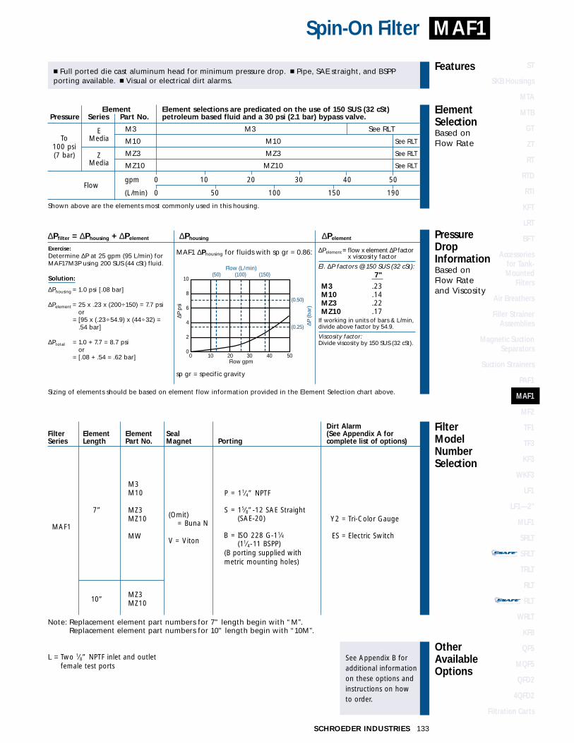
STAND-ALONE DISPOSABLE ELEMENT
™™
STAND-ALONE DISPOSABLE ELEMENT
™™
FilterModelNumberSelection
OtherAvailableOptions
See Appendix B foradditional informationon these options andinstructions on how to order.
PressureDropInformationBased on Flow Rateand Viscosity
ElementSelectionBased on Flow Rate
Features
133SCHROEDER INDUSTRIES
Spin-On Filter MAF1
Dirt AlarmFilter Element Element Seal (See Appendix A forSeries Length Part No. Magnet Porting complete list of options)
M3M10
MZ3MZ10
MW
MZ3MZ10
7”
10”
MAF1
(Omit) = Buna N
V = Viton
P = 11⁄4” NPTF
S = 15⁄8”-12 SAE Straight(SAE-20)
B = ISO 228 G-11⁄4(11⁄4-11 BSPP)
(B porting supplied with metric mounting holes)
Element Element selections are predicated on the use of 150 SUS (32 cSt) Pressure Series Part No. petroleum based fluid and a 30 psi (2.1 bar) bypass valve.
E M3 M3 See RLTMedia M10 M10 See RLT
Z MZ3 MZ3 See RLTMedia MZ10 MZ10 See RLT
Flowgpm 0 10 20 30 40 50
(L/min) 0 50 100 150 190
Shown above are the elements most commonly used in this housing.
� Full ported die cast aluminum head for minimum pressure drop. � Pipe, SAE straight, and BSPP porting available. � Visual or electrical dirt alarms.
To100 psi(7 bar)
MAF1 ∆Phousing for fluids with sp gr = 0.86: ∆Pelement= flow x element ∆P factor x viscosity factor
El. ∆P factors @ 150 SUS (32 cSt):7"
M3 .23M10 .14MZ3 .22MZ10 .17
If working in units of bars & L/min,divide above factor by 54.9.
Viscosity factor:Divide viscosity by 150 SUS (32 cSt).
∆Pfilter = ∆Phousing + ∆Pelement ∆Phousing ∆Pelement
Exercise:Determine ∆P at 25 gpm (95 L/min) forMAF17M3P using 200 SUS (44 cSt) fluid.
Solution:
∆Phousing = 1.0 psi [.08 bar]
∆Pelement = 25 x .23 x (200÷150) = 7.7 psior
∆Pelement = [95 x (.23÷54.9) x (44÷32) = .54 bar]
∆Ptotal = 1.0 + 7.7 = 8.7 psior
∆Pelement = [.08 + .54 = .62 bar]
Sizing of elements should be based on element flow information provided in the Element Selection chart above.
sp gr = specific gravity
(0.25)
(0.50)
(50) (150)(100)10
8
6
4
2
0 0 10 20 30 40 50
Flow gpm
Flow (L/min)
∆P (b
ar)
∆P p
si
Y2 = Tri-Color Gauge
ES = Electric Switch
L = Two 1⁄8” NPTF inlet and outletfemale test ports
Note: Replacement element part numbers for 7" length begin with “M”.Replacement element part numbers for 10" length begin with “10M”.
ST
SKB Housings
MTA
MTB
GT
ZT
RT
RTD
RTI
KFT
LRT
BFT
Accessories for Tank-Mounted
Filters
Air Breathers
Filler StrainerAssemblies
Magnetic SuctionSeparators
Suction Strainers
PAF1
MAF1
MF2
TF1
TF3
KF3
WKF3
LF1
LF1—2"
MLF1
SRLT
SRLT
TRLT
RLT
RLT
WRLT
KF8
QF5
MQF5
QFD2
4QFD2
Filtration Carts
STAND-ALONE DISPOSABLE ELEMENT
™™
STAND-ALONE DISPOSABLE ELEMENT
™™

FluidCompatibility
Type Fluid Appropriate Schroeder MediaPetroleum Based Fluids All Paper (E) and Synthetic (Z) media
High Water Content Z3, Z10Invert Emulsions Z10
Water Glycols Z10Note: Contact factory regarding use of E Media in High Water Content, Invert Emulsion and Water Glycol Applications.
For more information, refer toFluid Compatibility:Fire Resistant Fluids,pages 19 and 20.
SCHROEDER INDUSTRIES134
Absolute Rating Per ISO 4572/NFPA T3.10.8.8 Abs. Rating wrt ISO 16889 Using automated particle counter (APC) calibrated per ISO 4402 Using APC calibrated per ISO 11171 Dirt Holding
Element ßx ≥ 75 ßx ≥ 100 ßx ≥ 200 ßx(c) ≥ 200 ßx(c) ≥ 1000 Capacity gm
M3 6.8 7.5 10.0 N/A N/A 50
M10 15.5 16.2 18.0 N/A N/A 37
MZ3 <1.0 <1.0 <2.0 4.7 5.8 105
MZ10 7.4 8.2 10.0 10.0 12.7 104
Element Collapse Rating: 100 psid (7 bar)Flow Direction: Outside In
Element Nominal Dimensions: 7M: 5.0” (125 mm) O.D. x 7.0” (180 mm) long10M: 5.0” (125 mm) O.D. x 10.5” (261 mm) long
Flow Rating: Up to 60 gpm (230 L/min) for 150 SUS (32 cSt) fluids
Max. Operating Pressure: 150 psi (10 bar)
Min. Yield Pressure: 250 psi (17 bar)
Rated Fatigue Pressure: Contact factory
Temp. Range: -20°F to 225°F (-29°C to 107°C)
Bypass Setting: Cracking: 30 psi (2 bar)Full Flow: 48 psi (3 bar)
Porting Head: Cast IronElement Case: Steel
Weight of MF2-7M: 8.6 lbs. (3.9 kg)
Element Change Clearance: 1.50” (40 mm)
Filter Housing
Specifications
60 gpm230 L/min
150 psi10 bar
Spin-On Filter
ElementPerformanceInformation
Metric dimensions in ( ).Model No. of filter in photograph is MF27M10SD5.
MF2
IN
OU
T (32)
(60)
10M
= 1
0.50
(26
1)
(129)
2.75
5.50
(140)
(70)
(70)
(140)
(24)
(24)
.50-13UNC-2B X .62 (16) DEEPORM12 x 1.75 x (16) DEEP(2) MOUNTING HOLES
5.50
2.75
7M =
6.8
8 (1
75)
5.06
OR ELECTRIC SWITCHOPTIONAL DIRT ALARM
.94
.94
1.25
2.34
Ø
4.50 MAX.(114)
SPIN-ON THREAD=1.50-16UN-2B

STAND-ALONE DISPOSABLE ELEMENT
™™
STAND-ALONE DISPOSABLE ELEMENT
™™
FilterModelNumberSelection
OtherAvailableOptions
See Appendix B foradditional informationon these options andinstructions on how to order.
PressureDropInformationBased on Flow Rateand Viscosity
ElementSelectionBased on Flow Rate
Features
135SCHROEDER INDUSTRIES
MF2Spin-On Filter
Dirt AlarmFilter Element Element Seal (See Appendix A for Series Length Part No. Material Porting complete list of options)
M3M10
MZ3MZ10
MW
7”
MF2
(Omit) = Buna N
V = Viton
P = 11⁄4” NPTF
S = 15⁄8”-12 SAE Straight(SAE-20)
B = ISO 228 G-11⁄4(11⁄4 -11 BSPP)
(B porting supplied with metric mounting holes)
Element Element selections are predicated on the use of 150 SUS (32 cSt) Pressure Series Part No. petroleum based fluid and a 30 psi (2.1 bar) bypass valve.
E 7M3 7M3 See RLTMedia 7M10 7M10 See RLT
Z 7MZ3 7MZ3 See RLTMedia 7MZ10 7MZ10 See RLT
Flowgpm 0 20 30 40 50 60
(L/min) 0 50 100 150 230
Shown above are the elements most commonly used in this housing.
� Full ported cast iron head for minimum pressure drop. � Pipe, SAE straight, and BSPP porting available. � Differential pressure cartridge dirt alarm.
To150 psi(10 bar)
MF2 ∆Phousing for fluids with sp gr = 0.86: ∆Pelement= flow x element ∆P factor x viscosity factor
El. ∆P factors @ 150 SUS (32 cSt):M
M3 .23M10 .14MZ3 .22MZ10 .17
If working in units of bars & L/min,divide above factor by 54.9.
Viscosity factor:Divide viscosity by 150 SUS (32 cSt).
∆Pfilter = ∆Phousing + ∆Pelement ∆Phousing ∆Pelement
Exercise:Determine ∆P at 30 gpm (115 L/min) forMF27MZ3D5 using 200 SUS (44 cSt) fluid.
Solution:
∆Phousing = 3.0 psi [.22 bar]
∆Pelement = 30 x .22 x (200÷150) = 8.8 psior
∆Pelement = [115 x (.22÷54.9) x (44÷32) = .63 bar]
∆Ptotal = 3.0 + 8.8 = 11.8 psior
∆Pelement = [.22 + .63 = .83 bar]
Sizing of elements should be based on element flow information provided in the Element Selection chart above.
sp gr = specific gravity
(0.25)
(0.75)
(0.5)
(25) (125) (175)(75)12
10
8
6
4
2
0 0 10 20 30 40 50 60
Flow gpm
Flow (L/min)
∆P (b
ar)
∆P p
si
D5 = Cartridge
Electric Cartridge:MS5AC/DC/LC Family
(See Appendix A)
MZ3MZ1010”
Note: Replacement element part numbers for 7" length begin with “M”.Replacement element part numbers for 10" length begin with “10M”.
ST
SKB Housings
MTA
MTB
GT
ZT
RT
RTD
RTI
KFT
LRT
BFT
Accessories for Tank-Mounted
Filters
Air Breathers
Filler StrainerAssemblies
Magnetic SuctionSeparators
Suction Strainers
PAF1
MAF1
MF2
TF1
TF3
KF3
WKF3
LF1
LF1—2"
MLF1
SRLT
SRLT
TRLT
RLT
RLT
WRLT
KF8
QF5
MQF5
QFD2
4QFD2
Filtration Carts
STAND-ALONE DISPOSABLE ELEMENT
™™
STAND-ALONE DISPOSABLE ELEMENT
™™

FluidCompatibility
Type Fluid Appropriate Schroeder MediaPetroleum Based Fluids All Paper (E) and Synthetic (Z) media
High Water Content Z1, Z3, Z5, Z10, Z25Invert Emulsions Z10, Z25
Water Glycols Z3, Z5, Z10, Z25Phosphate Esters All Z media with EPR Seals
Skydrol Z3H.5, Z5H.5, Z10H.5 and Z25H.5 Note: Contact factory regarding use of E Media in High Water Content, Invert Emulsion and Water Glycol Applications.
For more information, refer toFluid Compatibility:Fire Resistant Fluids,pages 19 and 20.
SCHROEDER INDUSTRIES136
Absolute Rating Per ISO 4572/NFPA T3.10.8.8 Abs. Rating wrt ISO 16889 Using automated particle counter (APC) calibrated per ISO 4402 Using APC calibrated per ISO 11171 Dirt Holding
Element ßx ≥ 75 ßx ≥ 100 ßx ≥ 200 ßx(c) ≥ 200 ßx(c) ≥ 1000 Capacity gm
A3 6.8 7.5 10.0 N/A N/A 16
A10 15.5 16.2 18.0 N/A N/A 13
AZ1 <1.0 <1.0 <1.0 <4.0 4.2 25
AZ3 <1.0 <1.0 <2.0 4.7 5.8 26
AZ5 2.5 3.0 4.0 6.5 7.5 22
AZ10 7.4 8.2 10.0 10.0 12.7 28
AZ25 18.0 20.0 22.5 19.0 24.0 28
Element Collapse Rating: 150 psid (10 bar)Flow Direction: Outside In
Element Nominal Dimensions: 3.0” (75 mm) O.D. x 4.5” (115 mm) long
Flow Rating: Up to 30 gpm (120 L/min) for 150 SUS (32 cSt) fluids
Max. Operating Pressure: 300 psi (20 bar)
Min. Yield Pressure: 1200 psi (80 bar)
Rated Fatigue Pressure: 270 psi (19 bar), per NFPA T2.6.1-1974
Temp. Range: -20°F to 225°F (-29°C to 107°C)
Bypass Setting: Cracking: 30 psi (2 bar)Full Flow: 51 psi (4 bar)
Porting Head: Anodized Cast AluminumElement Case: Steel
Weight of TF1-1A: 5.1 lbs. (2.3 kg)Weight of TF1-2A: 6.3 lbs. (2.9 kg)
Element Change Clearance: 3.50” (90 mm)
Filter Housing
Specifications
30 gpm120 L/min
300 psi20 bar
Return Line Filter
ElementPerformanceInformation
TF1
Metric dimensions in ( ).Model No. of filter in photograph is TF1AZ10SD5.
1.38(35)
1A =
9.3
1 (2
36)
IN
3.50(89)
4.50 MAX.
OPTIONAL DIRT ALARMOR ELECTRIC SWITCH
(114)
2A =
14.
12 (
359)
Ø
OUTIN
(114)
(108)4.25
4.50
OUT
AA
.38-16UNC-2B x .50 (13) DEEPORM10 x 1.5 x (13) DEEP(2) MOUNTING HOLES
VIEW A-A
.38(10)
1.50(38)
.88
(22)

� Pipe, SAE straight, flange, and BSPP porting available.
FilterModelNumberSelection
OtherAvailableOptions
See Appendix B foradditional informationon these options andinstructions on how to order.
PressureDropInformationBased on Flow Rateand Viscosity
ElementSelectionBased on Flow Rate
Features
137SCHROEDER INDUSTRIES
TF1Return Line Filter
TF1 ∆Phousing for fluids with sp gr = 0.86:
∆Pfilter = ∆Phousing + ∆Pelement ∆Phousing ∆Pelement
Exercise:Determine ∆P at 20 gpm (75 L/min) forTF12AZ3PD using 200 SUS (44 cSt) fluid.
Solution:
∆Phousing = 4.5 psi [.30 bar]
∆Pelement = 20 x .25 x (200÷150) = 6.7 psior
∆Pelement = [75 x (.25÷54.9) x (44÷32) = .47 bar]
∆Ptotal = 4.5 + 6.7 = 11.2 psior
∆Pelement = [.30 + .47 = .77 bar]
Sizing of elements should be based on element flow information provided in the Element Selection chart above.
sp gr = specific gravity
(0.25)
(0.50)
(25) (50) (100)(75)10
8
6
4
2
0 0 10 20 30
Flow gpm
Flow (L/min)
∆P (b
ar)
∆P p
si
Element Element selections are predicated on the use of 150 SUS (32 cSt) Pressure Series Part No. petroleum based fluid and a 30 psi (2.1 bar) bypass valve.
EA3 1A3 2A3
MediaA10 1A10 2A10A25 1A25AZ1 1AZ1 2AZ1AZ3 1AZ3 2AZ3
ZAZ5 AZ5MediaAZ10 AZ10AZ25 AZ25
Flowgpm 0 10 20 30
(L/min) 0 25 50 75 100 120
Shown above are the elements most commonly used in this housing.
To300 psi(20 bar)
∆Pelement= flow x element ∆P factor x viscosity factor
El. ∆P factors @ 150 SUS (32 cSt):1A 2A
A3 .53 .27A10 .36 .18A25 .05 .03AZ1 .70 .35AZ3 .50 .25AZ5 .32 .16AZ10 .25 .13AZ25 .14 .07
If working in units of bars & L/min,divide above factor by 54.9.
Viscosity factor:Divide viscosity by 150 SUS (32 cSt).
L = Two 1⁄4” NPTF inlet & outlet femaletest ports
N = No-Element indicator
G440 = 1⁄2” drain on bottom of housing
P = 1” NPTF
S = 15⁄16”-12 SAE Straight(SAE-16)
F = 1” SAE J518 4-BoltFlange Code 61*
B = ISO 228 G-1(1-11 BSPP)
(B porting supplied with metric mounting holes)
(Omit) = Buna N
H = EPR
V = Viton
1
2
Dirt AlarmFilter No. of Element Seal (See Appendix A for Series Elements Part No. Material Porting complete list of options)
**Not available with Dirt Alarm.**Only available with Buna N seals.
A3**A10**A25**
AZ1AZ3AZ5AZ10AZ25
AM10AM60
TF1
D = PointerD5 = CartridgeMS = Cam Operated
Electric SwitchMS2 = Cam Operated
Electric Switch
Electric Cartridge:MS5AC/DC/LC Family
(See Appendix A)
MS15DC= DC Switch (SPST)
ST
SKB Housings
MTA
MTB
GT
ZT
RT
RTD
RTI
KFT
LRT
BFT
Accessories for Tank-Mounted
Filters
Air Breathers
Filler StrainerAssemblies
Magnetic SuctionSeparators
Suction Strainers
PAF1
MAF1
MF2
TF1
TF3
KF3
WKF3
LF1
LF1—2"
MLF1
SRLT
SRLT
TRLT
RLT
RLT
WRLT
KF8
QF5
MQF5
QFD2
4QFD2
Filtration Carts
STAND-ALONE DISPOSABLE ELEMENT
™™
STAND-ALONE DISPOSABLE ELEMENT
™™

FluidCompatibility
Type Fluid Appropriate Schroeder MediaPetroleum Based Fluids All Paper (E) and Synthetic (Z) media
High Water Content Z1, Z3, Z5, Z10, Z25Invert Emulsions Z10, Z25
Water Glycols Z3, Z5, Z10, Z25Phosphate Esters All Z media with EPR Seals
Skydrol Z3H.5, Z5H.5, Z10H.5 and Z25H.5 Note: Contact factory regarding use of E Media in High Water Content, Invert Emulsion and Water Glycol Applications.
For more information, refer toFluid Compatibility:Fire Resistant Fluids,pages 19 and 20.
SCHROEDER INDUSTRIES138
Absolute Rating Per ISO 4572/NFPA T3.10.8.8 Abs. Rating wrt ISO 16889 Using automated particle counter (APC) calibrated per ISO 4402 Using APC calibrated per ISO 11171 Dirt Holding
Element ßx ≥ 75 ßx ≥ 100 ßx ≥ 200 ßx(c) ≥ 200 ßx(c) ≥ 1000 Capacity gm
8T3 6.8 7.5 10.0 N/A N/A 39
8T10 15.5 16.2 18.0 N/A N/A 32
8TZ1 <1.0 <1.0 <1.0 <4.0 4.2 51
8TZ3 <1.0 <1.0 <2.0 4.7 5.8 52
8TZ5 2.5 3.0 4.0 6.5 7.5 43
8TZ10 7.4 8.2 10.0 10.0 12.7 55
8TZ25 18.0 20.0 22.5 19.0 24.0 53
Element Collapse Rating: 150 psid (10 bar)Flow Direction: Outside In
Element Nominal Dimensions: 3.1” (80 mm) O.D. x 8.0” (205 mm) long
Flow Rating: Up to 30 gpm (120 L/min) for 150 SUS (32 cSt) fluids
Max. Operating Pressure: 300 psi (20 bar)
Min. Yield Pressure: 1200 psi (80 bar)
Rated Fatigue Pressure: 270 psi (19 bar), per NFPA T2.6.1-1974
Temp. Range: -20°F to 225°F (-29°C to 107°C)
Bypass Setting: Cracking: 50 psi (3 bar)Full Flow: 72 psi (5 bar)
Porting Head: Anodized Cast AluminumElement Case: Steel
Weight of TF3-8T: 6.7 lbs. (3.0 kg)
Element Change Clearance: 3.50” (90 mm)
Filter Housing
Specifications
30 gpm120 L/min
300 psi20 bar
Return Line Filter
ElementPerformanceInformation
TF3
Metric dimensions in ( ).Model No. of filter in photograph is TF38T10SD5.
(35)
8T =
14.
12 (
359)
IN
3.50(89).38-16UNC-2B x .50 (13) DEEP
ORM10 x 1.5 x (13) DEEP(2) MOUNTING HOLES
IN
(114)
(108)
4.50 MAX.
OPTIONAL DIRT ALARMOR ELECTRIC SWITCH
(114)
Ø
4.25
4.50
OUT
1.38
VIEW A-A
AA
OUT
.38(10)
1.50(38)
.88
(22)

FilterModelNumberSelection
OtherAvailableOptions
See Appendix B foradditional informationon these options andinstructions on how to order.
PressureDropInformationBased on Flow Rateand Viscosity
ElementSelectionBased on Flow Rate
Features
139SCHROEDER INDUSTRIES
TF3Return Line Filter
� Meets HF3 automotive standard. � Pipe, SAE straight, flange, and BSPP porting available.
TF3 ∆Phousing for fluids with sp gr = 0.86:
∆Pfilter = ∆Phousing + ∆Pelement ∆Phousing ∆Pelement
Exercise:Determine ∆P at 15 gpm (57 L/min) forTF38T10PD5 using 200 SUS (44 cSt) fluid.
Solution:
∆Phousing = 3.0 psi [.20 bar]
∆Pelement = 15 x .09 x (200÷150) = 1.8 psior
∆Pelement = [57 x (.09÷54.9) x (44÷32) = .12 bar]
∆Ptotal = 3.0 + 1.8 = 4.8 psior
∆Pelement = [.20 + .12 = .32 bar]
Sizing of elements should be based on element flow information provided in the Element Selection chart above.
sp gr = specific gravity
(0.25)
(0.50)
(25) (50) (100)(75)10
8
6
4
2
0 0 10 20 30
Flow gpm
Flow (L/min)
∆P (b
ar)
∆P p
si
Element Element selections are predicated on the use of 150 SUS (32 cSt) Pressure Series Part No. petroleum based fluid and a 50 psi (3.4 bar) bypass valve.
8TZ1 8TZ1 See RLT8TZ3 8TZ3
Z 8TZ5 8TZ5Media8TZ10 8TZ108TZ25 8TZ25
Flowgpm 0 10 20 30
(L/min) 0 25 50 75 100 120
Shown above are the elements most commonly used in this housing.
To300 psi(20 bar)
∆Pelement= flow x element ∆P factor x viscosity factor
El. ∆P factors @ 150 SUS (32 cSt):
8T3 .258T10 .098T25 .028TZ1 .378TZ3 .218TZ5 .138TZ10 .118TZ25 .08
If working in units of bars & L/min,divide above factor by 54.9.
Viscosity factor:Divide viscosity by 150 SUS (32 cSt).
L = Two 1⁄4” NPTF inlet & outlet femaletest ports
N = No-Element indicator
G440 = 1⁄2” drain on bottom of housing
P = 1” NPTF
S = 15⁄16”-12 SAE Straight(SAE-16)
F = 1” SAE J518 4-BoltFlange Code 61*
B = ISO 228 G-1(1-11 BSPP)
(B porting supplied with metric mounting holes)
(Omit) = Buna N
H = EPR
V = Viton
8”
Dirt AlarmFilter
Element Part No.Seal (See Appendix A for
Series Length Media Material Porting complete list of options)
**Bolt thread depth .63” (16 mm). Not available with Dirt Alarm.**Only available with Buna N seals.
T3**T10**T25
TZ1TZ3TZ5TZ10TZ25
TF3
D5 = Cartridge
Electric Cartridge:MS5AC/DC/LC Family
(See Appendix A)
ST
SKB Housings
MTA
MTB
GT
ZT
RT
RTD
RTI
KFT
LRT
BFT
Accessories for Tank-Mounted
Filters
Air Breathers
Filler StrainerAssemblies
Magnetic SuctionSeparators
Suction Strainers
PAF1
MAF1
MF2
TF1
TF3
KF3
WKF3
LF1
LF1—2"
MLF1
SRLT
SRLT
TRLT
RLT
RLT
WRLT
KF8
QF5
MQF5
QFD2
4QFD2
Filtration Carts
STAND-ALONE DISPOSABLE ELEMENT
™™
STAND-ALONE DISPOSABLE ELEMENT
™™
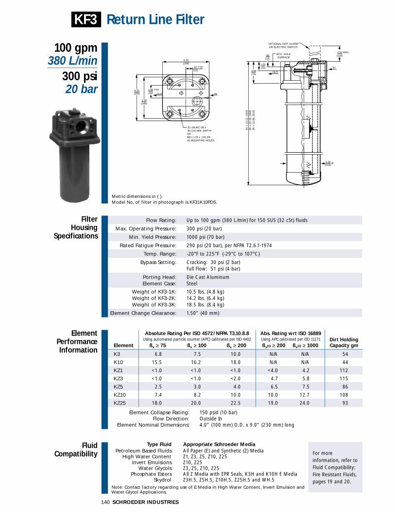
FluidCompatibility
Type Fluid Appropriate Schroeder MediaPetroleum Based Fluids All Paper (E) and Synthetic (Z) Media
High Water Content Z1, Z3, Z5, Z10, Z25Invert Emulsions Z10, Z25
Water Glycols Z3, Z5, Z10, Z25Phosphate Esters All Z Media with EPR Seals, K3H and K10H E Media
Skydrol Z3H.5, Z5H.5, Z10H.5, Z25H.5 and WH.5 Note: Contact factory regarding use of E Media in High Water Content, Invert Emulsion and Water Glycol Applications.
For more information, refer toFluid Compatibility:Fire Resistant Fluids,pages 19 and 20.
SCHROEDER INDUSTRIES140
Absolute Rating Per ISO 4572/NFPA T3.10.8.8 Abs. Rating wrt ISO 16889 Using automated particle counter (APC) calibrated per ISO 4402 Using APC calibrated per ISO 11171 Dirt Holding
Element ßx ≥ 75 ßx ≥ 100 ßx ≥ 200 ßx(c) ≥ 200 ßx(c) ≥ 1000 Capacity gm
K3 6.8 7.5 10.0 N/A N/A 54
K10 15.5 16.2 18.0 N/A N/A 44
KZ1 <1.0 <1.0 <1.0 <4.0 4.2 112
KZ3 <1.0 <1.0 <2.0 4.7 5.8 115
KZ5 2.5 3.0 4.0 6.5 7.5 86
KZ10 7.4 8.2 10.0 10.0 12.7 108
KZ25 18.0 20.0 22.5 19.0 24.0 93
Element Collapse Rating: 150 psid (10 bar)Flow Direction: Outside In
Element Nominal Dimensions: 4.0” (100 mm) O.D. x 9.0” (230 mm) long
Flow Rating: Up to 100 gpm (380 L/min) for 150 SUS (32 cSt) fluids
Max. Operating Pressure: 300 psi (20 bar)
Min. Yield Pressure: 1000 psi (70 bar)
Rated Fatigue Pressure: 290 psi (20 bar), per NFPA T2.6.1-1974
Temp. Range: -20°F to 225°F (-29°C to 107°C)
Bypass Setting: Cracking: 30 psi (2 bar)Full Flow: 51 psi (4 bar)
Porting Head: Die Cast AluminumElement Case: Steel
Weight of KF3-1K: 10.5 lbs. (4.8 kg)Weight of KF3-2K: 14.2 lbs. (6.4 kg)Weight of KF3-3K: 18.5 lbs. (8.4 kg)
Element Change Clearance: 1.50” (40 mm)
Filter Housing
Specifications
100 gpm380 L/min
300 psi20 bar
Return Line Filter
ElementPerformanceInformation
KF3
Metric dimensions in ( ).Model No. of filter in photograph is KF31K10PD5.
(13)
4.50 MAX.
1.25 (32)
(76)
1K =
13.
12 (
333)
2K =
22.
38 (
568)
3K =
31.
88 (
810)
(119)
.87 TYP(22)
(159)
(43)
(140)
INOUT
.31-18UNC-2B x
.60 (15) MIN. DEPTHORM8 x 1.25 x (15) DP.(4) MOUNTING HOLES
6.25
6.25(159)
5.50
IN
OUT
4.68 Ø
(114)
OPTIONAL DIRT ALARMOR ELECTRIC SWITCH
3.00
MTG. HOLESURFACE
1.68 TYP
.50

FilterModelNumberSelection
OtherAvailableOptions
See Appendix B foradditional informationon these options andinstructions on how to order.
PressureDropInformationBased on Flow Rateand Viscosity
ElementSelectionBased on Flow Rate
Features
141SCHROEDER INDUSTRIES
KF3Return Line Filter
Element Element selections are predicated on the use of 150 SUS (32 cSt) Pressure Series Part No. petroleum based fluid and a 30 psi (2.1 bar) bypass valve.
EK3 1K3 2K3 3K3
Media K10 1K10 2K10 3K10
K25 1K25 2K25
KZ1 1KZ1 2KZ1 3KZ1
ZKZ3 1KZ3 2KZ3
Media KZ5 1KZ5 2KZ5
KZ10 1KZ10
KZ25 1KZ25
Flowgpm 0 20 40 60 80 100
(L/min) 0 50 150 250 380Shown above are the elements most commonly used in this housing.
� Meets HF4 automotive standard. � Pipe, SAE straight, flange, and BSPP porting available.
To300 psi(20 bar)
KF3 ∆Phousing for fluids with sp gr = 0.86: ∆Pelement= flow x element ∆P factor x viscosity factor
El. ∆P factors @ 150 SUS (32 cSt):1K 2K 3K
K3 .25 .12 .08K10 .09 .05 .03K25 .02 .01 .01KZ1 .20 .10 .05KZ3 .10 .05 .03KZ5 .08 .04 .02KZ10 .05 .03 .02KZ25 .04 .02 .01
If working in units of bars & L/min,divide above factor by 54.9.
Viscosity factor:Divide viscosity by 150 SUS (32 cSt).
∆Pfilter = ∆Phousing + ∆Pelement ∆Phousing ∆Pelement
Exercise:Determine ∆P at 60 gpm (225 L/min) forKF32KZ5SD5 using 200 SUS (44 cSt) fluid.
Solution:
∆Phousing = 3.5 psi [.24 bar]
∆Pelement = 60 x .04 x (200÷150) = 3.2 psior
∆Pelement = [225 x (.04÷54.9) x (44÷32) = .23 bar]
∆Ptotal = 3.5 + 3.2 = 6.7 psior
∆Pelement = [.24 + .23 = .47 bar]
Sizing of elements should be based on element flow information provided in the Element Selection chart above.
sp gr = specific gravity
(0.25)
(0.50)
(50) (150) (250) (350)8
6
4
2
0 0 20 40 60 80 100
Flow gpm
Flow (L/min)
∆P (b
ar)
∆P p
si
L = Two 1⁄4” NPTF inlet & outlet female test ports
N = No-Element indicator
G426 = 3⁄4” drain on bottom of housing G440 = 1⁄2” drain on bottom of housing
P = 11⁄2” NPTF
S = 17⁄8”-12 SAE Straight(SAE-24)
F = 11⁄2” SAE J518 4-Bolt Flange Code 61*
B = ISO 228 G-11⁄2(11⁄2-11 BSPP)
(B porting supplied with metric mounting holes)
(Omit) = Buna N
H = EPR***
V = Viton***
W = Buna N***
1
2
3
Dirt AlarmFilter No. of Element Seal (See Appendix A for Series Elements† Part No. Material Porting complete list of options)
***Bolt thread depth .63” (16 mm). †Double and triple stacking of K-size elements can bereplaced by single KK and 27K elements, respectively.***Not available with EPR seals.
***When “H”, “W”, & “V” seals are ordered, all aluminum filter parts are anodized.
K3K10K25**
KZ1KZ3KZ5KZ10KZ25
KWKM10KM25KM60
KF3
D = PointerMS = Cam Operated
Electric SwitchMS2 = Cam Operated
Electric SwitchD5 = Cartridge
Electric Cartridge:MS5AC/DC/LC Family
(See Appendix A)
MS15DC= DC Switch (SPST)
ST
SKB Housings
MTA
MTB
GT
ZT
RT
RTD
RTI
KFT
LRT
BFT
Accessories for Tank-Mounted
Filters
Air Breathers
Filler StrainerAssemblies
Magnetic SuctionSeparators
Suction Strainers
PAF1
MAF1
MF2
TF1
TF3
KF3
WKF3
LF1
LF1—2"
MLF1
SRLT
SRLT
TRLT
RLT
RLT
WRLT
KF8
QF5
MQF5
QFD2
4QFD2
Filtration Carts
STAND-ALONE DISPOSABLE ELEMENT
™™
STAND-ALONE DISPOSABLE ELEMENT
™™
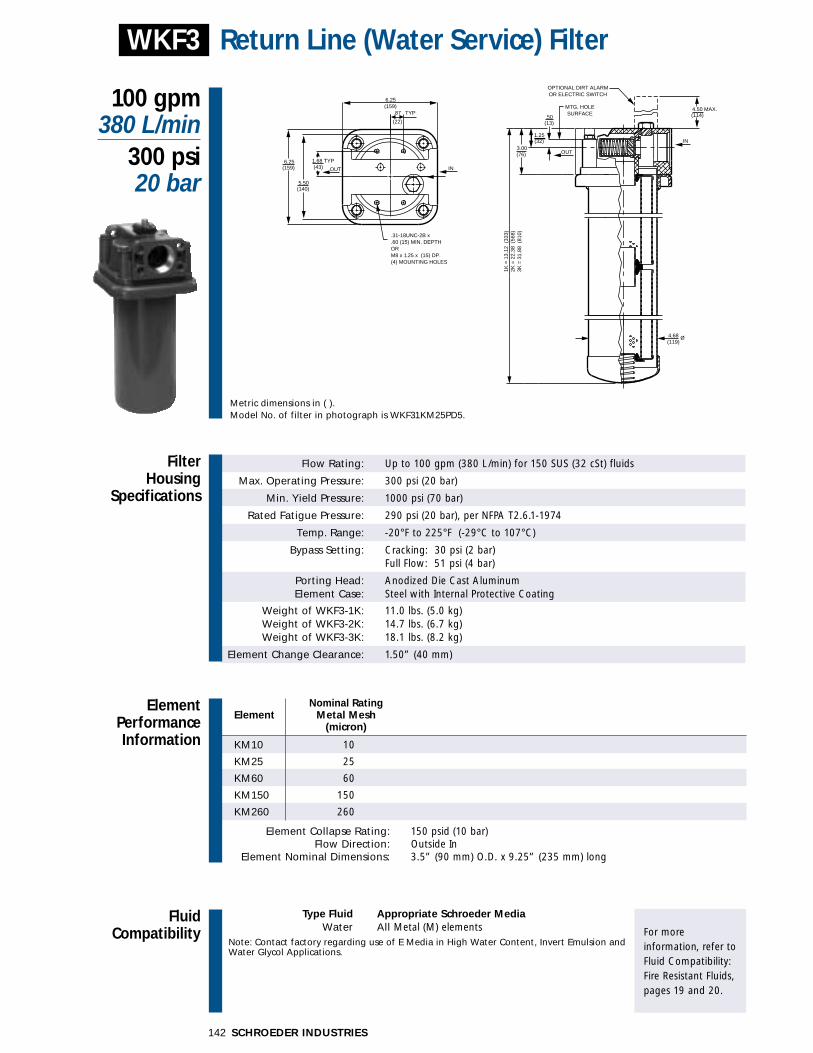
FluidCompatibility
Type Fluid Appropriate Schroeder MediaWater All Metal (M) elements
Note: Contact factory regarding use of E Media in High Water Content, Invert Emulsion and Water Glycol Applications.
For more information, refer toFluid Compatibility:Fire Resistant Fluids,pages 19 and 20.
SCHROEDER INDUSTRIES142
Nominal RatingElement Metal Mesh
(micron)
KM10 10
KM25 25
KM60 60
KM150 150
KM260 260
Element Collapse Rating: 150 psid (10 bar)Flow Direction: Outside In
Element Nominal Dimensions: 3.5” (90 mm) O.D. x 9.25” (235 mm) long
Flow Rating: Up to 100 gpm (380 L/min) for 150 SUS (32 cSt) fluids
Max. Operating Pressure: 300 psi (20 bar)
Min. Yield Pressure: 1000 psi (70 bar)
Rated Fatigue Pressure: 290 psi (20 bar), per NFPA T2.6.1-1974
Temp. Range: -20°F to 225°F (-29°C to 107°C)
Bypass Setting: Cracking: 30 psi (2 bar)Full Flow: 51 psi (4 bar)
Porting Head: Anodized Die Cast AluminumElement Case: Steel with Internal Protective Coating
Weight of WKF3-1K: 11.0 lbs. (5.0 kg)Weight of WKF3-2K: 14.7 lbs. (6.7 kg)Weight of WKF3-3K: 18.1 lbs. (8.2 kg)
Element Change Clearance: 1.50” (40 mm)
Filter Housing
Specifications
100 gpm380 L/min
300 psi20 bar
Return Line (Water Service) Filter
ElementPerformanceInformation
WKF3
Metric dimensions in ( ).Model No. of filter in photograph is WKF31KM25PD5.
(13)
(32)
4.50 MAX.(114).87
(22)
1.25
(76)
1K =
13.
12 (
333)
2K =
22.
38 (
568)
3K =
31.
88 (
810)
(119)
(159)
(43)
(140)
INOUT
.31-18UNC-2B x
.60 (15) MIN. DEPTHORM8 x 1.25 x (15) DP.(4) MOUNTING HOLES
6.25
6.25(159)
5.50
IN
OUT
4.68 Ø
OPTIONAL DIRT ALARMOR ELECTRIC SWITCH
3.00
MTG. HOLESURFACETYP
1.68 TYP
.50

143SCHROEDER INDUSTRIES
FilterModelNumberSelection
OtherAvailableOptions
See Appendix B foradditional informationon these options andinstructions on how to order.
PressureDropInformationBased on Flow Rateand Viscosity
ElementSelectionBased on Flow Rate
Features
WKF3Return Line (Water Service) Filter
Element Element selections are predicated on the use of water and a 30 psiPressure Series Part No. (2.1 bar) bypass valve.
KM10 1KM10
KM25 1KM25M KM60 1KM60
MediaKM150 1KM150
KM260 1KM260
Flowgpm 0 20 40 60 80 100
(L/min) 0 50 150 250 380
Shown above are the elements most commonly used in this housing.
� For use in water systems. � Furnished with cleanable metal elements.
To300 psi(20 bar)
WKF3 ∆Phousing for water: ∆Pelement= flow x element ∆P factor x viscosity factor
El. ∆P factors:
KM10 .08KM25 .06KM60 .01KM150 .01KM260 .01
If working in units of bars & L/min,divide above factor by 54.9.
∆Pfilter = ∆Phousing + ∆Pelement ∆Phousing ∆Pelement
Exercise:Determine ∆P at 50 gpm (190 L/min) forWKF31KM10P using water.
Solution:
∆Phousing = 2.6 psi [.14 bar]
∆Pelement = 50 x .08 = 4.0 psior
∆Pelement = [190 x (.08÷54.9) = .28 bar]
∆Ptotal = 2.6 + 4.0 = 6.6 psior
∆Pelement = [.14 + .28 = .42 bar]
Sizing of elements should be based on element flow information provided in the Element Selection chart above.
(0.25)
(0.50)
(50) (150) (250) (350)8
6
4
2
0 0 20 40 60 80 100
Flow gpm
Flow (L/min)
∆P (b
ar)
∆P p
si
L = Two 1⁄4” NPTF inlet & outlet femaletest ports
G426 = 3⁄4” drain on bottom of housing G440 = 1⁄2” drain on bottom of housing
P = 11⁄2” NPTF
S = 17⁄8”-12 SAE Straight(SAE-24)
F = 11⁄2” SAE J518 4-BoltFlange Code 61*
B = ISO 228 G-11⁄2(11⁄2-11 BSPP)
(B porting supplied with metric mounting holes)
(Omit) = Buna N
1
2
3
Dirt AlarmFilter No. of Element Seal (See Appendix A for Series Elements Part No. Material Porting complete list of options)
*Bolt thread depth .63” (16 mm).
KM10KM25KM60KM150KM260
WKF3
D = PointerMS = Cam Operated
Electric SwitchMS2 = Cam Operated
Electric SwitchD5 = Cartridge
Electric Cartridge:MS5AC/DC/LC Family
(See Appendix A)
ST
SKB Housings
MTA
MTB
GT
ZT
RT
RTD
RTI
KFT
LRT
BFT
Accessories for Tank-Mounted
Filters
Air Breathers
Filler StrainerAssemblies
Magnetic SuctionSeparators
Suction Strainers
PAF1
MAF1
MF2
TF1
TF3
KF3
WKF3
LF1
LF1—2"
MLF1
SRLT
SRLT
TRLT
RLT
RLT
WRLT
KF8
QF5
MQF5
QFD2
4QFD2
Filtration Carts
STAND-ALONE DISPOSABLE ELEMENT
™™
STAND-ALONE DISPOSABLE ELEMENT
™™

FluidCompatibility
Type Fluid Appropriate Schroeder MediaPetroleum Based Fluids All Paper (E) and Synthetic (Z) Media
High Water Content Z1, Z3, Z5, Z10, Z25Invert Emulsions Z10, Z25
Water Glycols Z3, Z5, Z10, Z25Phosphate Esters All Z Media with EPR Seals, K3H and K10H E Media
Skydrol Z3H.5, Z5H.5, Z10H.5, Z25H.5 and WH.5 Note: Contact factory regarding use of E Media in High Water Content, Invert Emulsion and Water Glycol Applications.
For more information, refer toFluid Compatibility:Fire Resistant Fluids,pages 19 and 20.
SCHROEDER INDUSTRIES144
Absolute Rating Per ISO 4572/NFPA T3.10.8.8 Abs. Rating wrt ISO 16889 Using automated particle counter (APC) calibrated per ISO 4402 Using APC calibrated per ISO 11171 Dirt Holding
Element ßx ≥ 75 ßx ≥ 100 ßx ≥ 200 ßx(c) ≥ 200 ßx(c) ≥ 1000 Capacity gm
K3 6.8 7.5 10.0 N/A N/A 54
K10 15.5 16.2 18.0 N/A N/A 44
KZ1 <1.0 <1.0 <1.0 <4.0 4.2 112
KZ3 <1.0 <1.0 <2.0 4.7 5.8 115
KZ5 2.5 3.0 4.0 6.5 7.5 86
KZ10 7.4 8.2 10.0 10.0 12.7 108
KZ25 18.0 20.0 22.5 19.0 24.0 93
Element Collapse Rating: 150 psid (10 bar)Flow Direction: Outside In
Element Nominal Dimensions: 4.0” (100 mm) O.D. x 9.0” (230 mm) long
Flow Rating: Up to 100 gpm (380 L/min) for 150 SUS (32 cSt) fluids
Max. Operating Pressure: 300 psi (20 bar)
Min. Yield Pressure: 1000 psi (70 bar)
Rated Fatigue Pressure: 250 psi (17 bar), per NFPA T2.6.1-1974
Temp. Range: -20°F to 225°F (-29°C to 107°C)
Bypass Setting: Cracking: 25 psi (2 bar)Full Flow: 60 psi (4 bar)
Porting Head: Anodized Cast AluminumElement Case: Steel
Weight of LF1-1K: 13.7 lbs. (6.2 kg)Weight of LF1-2K: 17.5 lbs. (7.9 kg)Weight of LF1-3K: 22.3 lbs. (10.1 kg)
Element Change Clearance: 2.00” (55 mm)
Filter Housing
Specifications
100 gpm380 L/min
300 psi20 bar
Return Line Filter
ElementPerformanceInformation
LF1
Metric dimensions in ( ).Model No. of filter in photograph is LF11K10PD.
1.881.88
4.69 Ø
5.62
1.50 MAX.
OPTIONAL DIRT ALARMOR ELECTRIC SWITCH
(38)
(48)
(119)
(143)
(159)
IN OUT
IN OUT
.38-16UNC-2B x .50(13) DP.ORM10 x 1.5 x (13) DP.(2) MOUNTING HOLES
1K =
14.
19 (
360)
2K =
23.
69 (
602)
3K =
32.
94 (
837)
6.25
.62
(51)
(16)
(44)
AA
VIEW A-A
INOUT
1.75 2.00
1.88

145SCHROEDER INDUSTRIES
FilterModelNumberSelection
OtherAvailableOptions
See Appendix B foradditional informationon these options andinstructions on how to order.
PressureDropInformationBased on Flow Rateand Viscosity
ElementSelectionBased on Flow Rate
Features
LF1Return Line Filter
� Meets HF4 automotive standard. � Pipe, SAE straight, flange, and BSPP porting available.
LF1 ∆Phousing for fluids with sp gr = 0.86:
∆Pfilter = ∆Phousing + ∆Pelement ∆Phousing ∆Pelement
Exercise:Determine ∆P at 40 gpm (150 L/min) forLF13K10SD5 using 200 SUS (44 cSt) fluid.
Solution:
∆Phousing = 2.5 psi [.18 bar]
∆Pelement = 40 x .03 x (200÷150) = 1.6 psior
∆Pelement = [150 x (.03÷54.9) x (44÷32) = .11 bar]
∆Ptotal = 2.5 + 1.6 = 4.1 psior
∆Pelement = [.18 + .11 = .29 bar]
Sizing of elements should be based on element flow information provided in the Element Selection chart above.
sp gr = specific gravity
(0.25)
(0.50)
(0.75)
(50) (150) (250) (350)12
10
8
6
4
2
0 0 20 40 60 80 100
Flow gpm
Flow (L/min)∆P
(bar
)
∆P p
si
∆Pelement= flow x element ∆P factor x viscosity factor
El. ∆P factors @ 150 SUS (32 cSt):1K 2K 3K
K3 .25 .12 .08K10 .09 .05 .03K25 .02 .01 .01KZ1 .20 .10 .05KZ3 .10 .05 .03KZ5 .08 .04 .02KZ10 .05 .03 .02KZ25 .04 .02 .01
If working in units of bars & L/min,divide above factor by 54.9.
Viscosity factor:Divide viscosity by 150 SUS (32 cSt).
Element Element selections are predicated on the use of 150 SUS (32 cSt) Pressure Series Part No. petroleum based fluid and a 25 psi (1.7 bar) bypass valve.
EK3 1K3 2K3 3K3
Media K10 1K10 2K10 3K10
K25 1K25 2K25
KZ1 1KZ1 2KZ1 3KZ1
ZKZ3 1KZ3 2KZ3 3KZ3
Media KZ5 1KZ5 2KZ5
KZ10 1KZ10
KZ25 1KZ25
Flowgpm 0 20 40 60 80 100
(L/min) 0 50 150 250 380Shown above are the elements most commonly used in this housing.
To300 psi(20 bar)
L = Two 1⁄4” NPTF inlet & outlet femaletest ports
G426 = 3⁄4” drain on bottom of housing G440 = 1⁄2” drain on bottom of housing
P = 11⁄2” NPTF
S = 17⁄8”-12 SAE Straight(SAE-24)
F = 11⁄2” SAE J518 4-BoltFlange Code 61*
B = ISO 228 G-11⁄2(11⁄2-11 BSPP)
(B porting supplied with metric mounting holes)
For 2” porting, See KF8 or contact factory.
(Omit) = Buna N
H = EPR
V = Viton
1
2
3
Dirt AlarmFilter No. of Element Seal (See Appendix A forSeries Elements† Part No. Material Porting complete list of options)
**Bolt thread depth .63” (16 mm). †Double and triple stacking of K-size elements can bereplaced by single KK and 27K elements, respectively.** Not available with EPR seals.
K3K10K25**
KZ1KZ3KZ5KZ10KZ25
KWKM10KM25KM60
LF1D = Pointer
MS = Electric CamOperated
ST
SKB Housings
MTA
MTB
GT
ZT
RT
RTD
RTI
KFT
LRT
BFT
Accessories for Tank-Mounted
Filters
Air Breathers
Filler StrainerAssemblies
Magnetic SuctionSeparators
Suction Strainers
PAF1
MAF1
MF2
TF1
TF3
KF3
WKF3
LF1
LF1—2"
MLF1
SRLT
SRLT
TRLT
RLT
RLT
WRLT
KF8
QF5
MQF5
QFD2
4QFD2
Filtration Carts
STAND-ALONE DISPOSABLE ELEMENT
™™
STAND-ALONE DISPOSABLE ELEMENT
™™

SCHROEDER INDUSTRIES146
120 gpm455 L/min
300 psi20 bar
Return Line Filter With 2" PortsLF1
Filter Housing
Specifications
1.881.88
4.69 Ø
5.62
1.50 MAX.
OPTIONAL DIRT ALARMOR ELECTRIC SWITCH
(38)
(48)
(119)
(143)
(159)
IN OUT
IN OUT
.38-16UNC-2B x .50(13) DP.ORM10 x 1.5 x (13) DP.(2) MOUNTING HOLES
18L=
23.
75 (
603)
6.25
.62
(51)
(16)
(44)
AA
VIEW A-A
INOUT
1.75 2.00
1.88
FluidCompatibility
Type Fluid Appropriate Schroeder MediaPetroleum Based Fluids All Paper (E) and Synthetic (Z) Media
High Water Content Z1, Z3, Z5, Z10, Z25Invert Emulsions Z10, Z25
Water Glycols Z3, Z5, Z10, Z25Phosphate Esters All Z Media with EPR Seals
Skydrol Z3H.5, Z5H.5, Z10H.5 and Z25H.5Note: Contact factory regarding use of E Media in High Water Content, Invert Emulsion and Water Glycol Applications.
For more information, refer toFluid Compatibility:Fire Resistant Fluids,pages 19 and 20.
ElementPerformanceInformation
Flow Rating: Up to 120 gpm (455 L/min) for 150 SUS (32 cSt) fluids
Max. Operating Pressure: 300 psi (20 bar)
Min. Yield Pressure: 1000 psi (70 bar)
Rated Fatigue Pressure: 250 psi (17 bar), per NFPA T2.6.1-1974
Temp. Range: -20°F to 225°F (-29°C to 107°C)
Bypass Setting: Cracking: 30 psi (2.1 bar)Full Flow: 60 psi (4.1 bar)
Porting Head: Anodized Cast AluminumElement Case: Steel
Available Porting: 2" NPTF, 21⁄2-12 SAE Straight
Weight of LF1-18L: 17.5 lbs. (7.9 kg)
Element Change Clearance: 2.00” (55 mm)
Absolute Rating Per ISO 4572/NFPA T3.10.8.8 Abs. Rating wrt ISO 16889 Using automated particle counter (APC) calibrated per ISO 4402 Using APC calibrated per ISO 11171 Dirt Holding
Element ßx ≥ 75 ßx ≥ 100 ßx ≥ 200 ßx(c) ≥ 200 ßx(c) ≥ 1000 Capacity gm
18L3 6.8 7.5 10.0 N/A N/A 110
18L10 15.5 16.2 18.0 N/A N/A 88
18LZ1 <1.0 <1.0 <1.0 <4.0 4.2 200
18LZ3 <1.0 <1.0 <2.0 4.7 5.8 205
18LZ5 2.5 3.0 4.0 6.5 7.5 165
18LZ10 7.4 8.2 10.0 10.0 12.7 203
18LZ25 18.0 20.0 22.5 19.0 24.0 184
Element Collapse Rating: 150 psid (10 bar)Flow Direction: Outside In
Element Nominal Dimensions: 4.0” (100 mm) O.D. x 18.5” (470 mm) long
Metric dimensions in ( ).
NEWPRODUCT
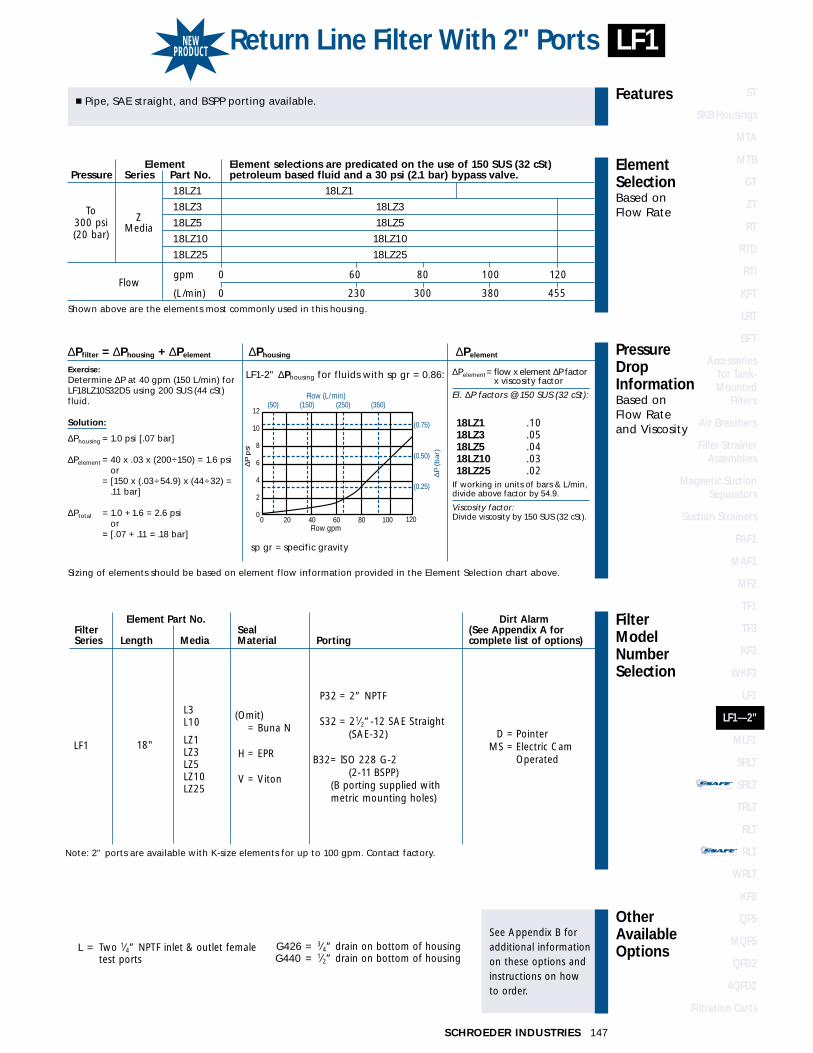
147SCHROEDER INDUSTRIES
STAND-ALONE DISPOSABLE ELEMENT
™™
STAND-ALONE DISPOSABLE ELEMENT
™™
Return Line Filter With 2" Ports LF1
FilterModelNumberSelection
OtherAvailableOptions
See Appendix B foradditional informationon these options andinstructions on how to order.
PressureDropInformationBased on Flow Rateand Viscosity
ElementSelectionBased on Flow Rate
Features� Pipe, SAE straight, and BSPP porting available.
LF1-2" ∆Phousing for fluids with sp gr = 0.86:
∆Pfilter = ∆Phousing + ∆Pelement ∆Phousing ∆Pelement
Exercise:Determine ∆P at 40 gpm (150 L/min) forLF18LZ10S32D5 using 200 SUS (44 cSt)fluid.
Solution:
∆Phousing = 1.0 psi [.07 bar]
∆Pelement = 40 x .03 x (200÷150) = 1.6 psior
∆Pelement = [150 x (.03÷54.9) x (44÷32) = .11 bar]
∆Ptotal = 1.0 + 1.6 = 2.6 psior
∆Pelement = [.07 + .11 = .18 bar]
Sizing of elements should be based on element flow information provided in the Element Selection chart above.
sp gr = specific gravity
(0.25)
(0.50)
(0.75)
(50) (150) (250) (350)12
10
8
6
4
2
0 0 20 40 60 80 100
Flow gpm
Flow (L/min)
∆P (
bar)
∆P p
si
120
∆Pelement= flow x element ∆P factor x viscosity factor
El. ∆P factors @ 150 SUS (32 cSt):
18LZ1 .1018LZ3 .0518LZ5 .0418LZ10 .0318LZ25 .02
If working in units of bars & L/min,divide above factor by 54.9.
Viscosity factor:Divide viscosity by 150 SUS (32 cSt).
Element Element selections are predicated on the use of 150 SUS (32 cSt) Pressure Series Part No. petroleum based fluid and a 30 psi (2.1 bar) bypass valve.
18LZ1 18LZ1
Z18LZ3 18LZ3
Media 18LZ5 18LZ5
18LZ10 18LZ10
18LZ25 18LZ25
Flowgpm 0 60 80 100 120
(L/min) 0 230 300 380 455Shown above are the elements most commonly used in this housing.
To300 psi(20 bar)
L = Two 1⁄4” NPTF inlet & outlet femaletest ports
G426 = 3⁄4” drain on bottom of housing G440 = 1⁄2” drain on bottom of housing
P32 = 2” NPTF
S32 = 21⁄2”-12 SAE Straight(SAE-32)
B32= ISO 228 G-2(2-11 BSPP)
(B porting supplied with metric mounting holes)
(Omit) = Buna N
H = EPR
V = Viton
18"
Element Part No. Dirt AlarmFilter Seal (See Appendix A forSeries Length Media Material Porting complete list of options)
Note: 2" ports are available with K-size elements for up to 100 gpm. Contact factory.
L3L10
LZ1LZ3LZ5LZ10LZ25
LF1D = Pointer
MS = Electric CamOperated
ST
SKB Housings
MTA
MTB
GT
ZT
RT
RTD
RTI
KFT
LRT
BFT
Accessories for Tank-Mounted
Filters
Air Breathers
Filler StrainerAssemblies
Magnetic SuctionSeparators
Suction Strainers
PAF1
MAF1
MF2
TF1
TF3
KF3
WKF3
LF1
LF1—2"
MLF1
SRLT
SRLT
TRLT
RLT
RLT
WRLT
KF8
QF5
MQF5
QFD2
4QFD2
Filtration Carts
STAND-ALONE DISPOSABLE ELEMENT
™™
STAND-ALONE DISPOSABLE ELEMENT
™™
NEWPRODUCT

SCHROEDER INDUSTRIES148
FluidCompatibility
Type Fluid Appropriate Schroeder MediaPetroleum Based Fluids All Paper (E) and Synthetic (Z) Media
High Water Content Z1, Z3, Z5, Z10, Z25Invert Emulsions Z10, Z25
Water Glycols Z3, Z5, Z10, Z25Phosphate Esters All Z Media with EPR Seals, K3H and K10H E Media
Skydrol Z3H.5, Z5H.5, Z10H.5, Z25H.5 and WH.5 Note: Contact factory regarding use of E Media in High Water Content, Invert Emulsion and Water Glycol Applications.
For more information, refer toFluid Compatibility:Fire Resistant Fluids,pages 19 and 20.
Absolute Rating Per ISO 4572/NFPA T3.10.8.8 Abs. Rating wrt ISO 16889 Using automated particle counter (APC) calibrated per ISO 4402 Using APC calibrated per ISO 11171 Dirt Holding
Element ßx ≥ 75 ßx ≥ 100 ßx ≥ 200 ßx(c) ≥ 200 ßx(c) ≥ 1000 Capacity gm
K3 6.8 7.5 10.0 N/A N/A 54
K10 15.5 16.2 18.0 N/A N/A 44
KZ1 <1.0 <1.0 <1.0 <4.0 4.2 112
KZ3 <1.0 <1.0 <2.0 4.7 5.8 115
KZ5 2.5 3.0 4.0 6.5 7.5 86
KZ10 7.4 8.2 10.0 10.0 12.7 108
KZ25 18.0 20.0 22.5 19.0 24.0 93
Element Collapse Rating: 150 psid (10 bar)Flow Direction: Outside In
Element Nominal Dimensions: 4.0” (100 mm) O.D. x 9.0” (230 mm) long
Flow Rating: Up to 200 gpm (760 L/min) for 150 SUS (32 cSt) fluids
Max. Operating Pressure: 300 psi (20 bar)
Min. Yield Pressure: 1000 psi (70 bar)
Rated Fatigue Pressure: 250 psi (17 bar), per NFPA T2.6.1-1974
Temp. Range: -20°F to 225°F (-29°C to 107°C)
Bypass Setting: Cracking: 25 psi (2 bar)Full Flow: 60 psi (4 bar)
Porting Head: Anodized Cast AluminumElement Case: Steel
Weight of MLF1-2K: 44.0 lbs. (20.0 kg)Weight of MLF1-4K: 50.0 lbs. (23.0 kg)Weight of MLF1-6K: 58.0 lbs. (26.0 kg)
Element Change Clearance: 2.00” (55 mm)
Filter Housing
Specifications
200 gpm760 L/min
300 psi20 bar
Top-Ported Return Line Filter
ElementPerformanceInformation
MLF1
Metric dimensions in ( ).Model No. of filter in photograph is MLF14K10PD.
3.00(76) 11.69
(297)
1.50 MAX.(38)
OPTIONAL DIRT ALARMOR ELECTRIC SWITCH
MANIFOLDMANIFOLD
.50-13UNC-2B x 1.00 (25) DEEP(4) MOUNTING HOLES (FROM BOTTOM)
2.25(57)
4.69(119)
Ø
IN
IN
2K =
14.
56 (
370)
4K =
24.
06 (
611)
6K =
33.
31 (
846) OUT
OUT
6.00(152)
4.25(108)
8.50(216)
12.88(327)
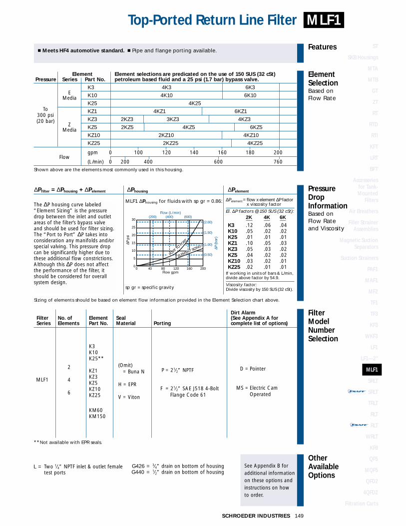
FilterModelNumberSelection
OtherAvailableOptions
See Appendix B foradditional informationon these options andinstructions on how to order.
PressureDropInformationBased on Flow Rateand Viscosity
ElementSelectionBased on Flow Rate
Features
149SCHROEDER INDUSTRIES
MLF1Top-Ported Return Line Filter
� Meets HF4 automotive standard. � Pipe and flange porting available.
MLF1 ∆Phousing for fluids with sp gr = 0.86:
∆Pfilter = ∆Phousing + ∆Pelement ∆Phousing ∆Pelement
Sizing of elements should be based on element flow information provided in the Element Selection chart above.
sp gr = specific gravity
(0.50)
(1.00)
(1.50)
(2.00)
(200) (400) (600)30
25
20
15
10
5
0 0 40 80 120 160 200
Flow gpm
Flow (L/min)∆P
(bar
)
∆P p
si
PORT T
O PORT
ELEMENT SIZING
Element Element selections are predicated on the use of 150 SUS (32 cSt) Pressure Series Part No. petroleum based fluid and a 25 psi (1.7 bar) bypass valve.
EK3 4K3 6K3
Media K10 4K10 6K10
K25 4K25
KZ1 4KZ1 6KZ1
ZKZ3 2KZ3 3KZ3 4KZ3
Media KZ5 2KZ5 4KZ5 6KZ5
KZ10 2KZ10 4KZ10
KZ25 2KZ25 4KZ25
Flowgpm 0 100 120 140 160 180 200
(L/min) 0 200 400 600 760Shown above are the elements most commonly used in this housing.
To300 psi(20 bar)
L = Two 1⁄4” NPTF inlet & outlet femaletest ports
G426 = 3⁄4” drain on bottom of housing G440 = 1⁄2” drain on bottom of housing
P = 21⁄2” NPTF
F = 21⁄2” SAE J518 4-BoltFlange Code 61
(Omit) = Buna N
H = EPR
V = Viton
2
4
6
Dirt AlarmFilter No. of Element Seal (See Appendix A for Series Elements Part No. Material Porting complete list of options)
**Not available with EPR seals.
K3K10K25**
KZ1KZ3KZ5KZ10KZ25
KM60KM150
MLF1
D = Pointer
MS = Electric CamOperated
∆Pelement= flow x element ∆P factor x viscosity factor
El. ∆P factors @ 150 SUS (32 cSt):2K 4K 6K
K3 .12 .06 .04K10 .05 .02 .02K25 .01 .01 .01KZ1 .10 .05 .03KZ3 .05 .03 .02KZ5 .04 .02 .02KZ10 .03 .02 .01KZ25 .02 .01 .01
If working in units of bars & L/min,divide above factor by 54.9.
Viscosity factor:Divide viscosity by 150 SUS (32 cSt).
The ∆P housing curve labeled“Element Sizing” is the pressuredrop between the inlet and outlet areas of the filter’s bypass valveand should be used for filter sizing.The “Port to Port” ∆P takes intoconsideration any manifolds and/orspecial valving. This pressure dropcan be significantly higher due tothese additional flow constrictions.Although this ∆P does not affectthe performance of the filter, itshould be considered for overallsystem design.
ST
SKB Housings
MTA
MTB
GT
ZT
RT
RTD
RTI
KFT
LRT
BFT
Accessories for Tank-Mounted
Filters
Air Breathers
Filler StrainerAssemblies
Magnetic SuctionSeparators
Suction Strainers
PAF1
MAF1
MF2
TF1
TF3
KF3
WKF3
LF1
LF1—2"
MLF1
SRLT
SRLT
TRLT
RLT
RLT
WRLT
KF8
QF5
MQF5
QFD2
4QFD2
Filtration Carts
STAND-ALONE DISPOSABLE ELEMENT
™™
STAND-ALONE DISPOSABLE ELEMENT
™™

FluidCompatibility
Type Fluid Appropriate Schroeder MediaPetroleum Based Fluids All Paper (E) and Synthetic (Z) media
High Water Content Z1, Z3, Z5, Z10, Z25Invert Emulsions Z10, Z25
Water Glycols Z3, Z5, Z10, Z25Phosphate Esters All Z media with EPR Seals
Skydrol Z3H.5, Z5H.5, Z10H.5 and Z25H.5Note: Contact factory regarding use of E Media in High Water Content, Invert Emulsion and Water Glycol Applications.
For more information, refer toFluid Compatibility:Fire Resistant Fluids,pages 19 and 20.
SCHROEDER INDUSTRIES150
Absolute Rating Per ISO 4572/NFPA T3.10.8.8 Abs. Rating wrt ISO 16889 Using automated particle counter (APC) calibrated per ISO 4402 Using APC calibrated per ISO 11171 Dirt Holding
Element ßx ≥ 75 ßx ≥ 100 ßx ≥ 200 ßx(c) ≥ 200 ßx(c) ≥ 1000 Capacity gm
6R3 6.8 7.5 10.0 N/A N/A 5
6R10 15.5 16.2 18.0 N/A N/A 6
6RZ1 <1.0 <1.0 <1.0 <4.0 4.2 15
6RZ3 <1.0 <1.0 <2.0 4.7 5.8 15
6RZ5 2.5 3.0 4.0 6.5 7.5 12
6RZ10 7.4 8.2 10.0 10.0 12.7 14
6RZ25 18.0 20.0 22.5 19.0 24.0 25
Element Collapse Rating: 150 psid (10 bar)Flow Direction: Outside In
Element Nominal Dimensions: 2.0” (50 mm) O.D. x 6.0” (150 mm) long
Flow Rating: Up to 25 gpm (100 L/min) for 150 SUS (32 cSt) fluids
Max. Operating Pressure: 1400 psi (100 bar)
Min. Yield Pressure: 4000 psi (276 bar)
Rated Fatigue Pressure: 750 psi (52 bar) per NFPA T2.6.1-R1-1991
Temp. Range: -20°F to 225°F (-29°C to 107°C)
Bypass Setting: Cracking: 40 psi (2.8 bar)Full Flow: 55 psi (3.8 bar)
Porting Head: Die Cast AluminumElement Case: Steel
Weight of SRLT-6R: 3.0 lbs. (1.4 kg)
Element Change Clearance: 2.75” (70 mm)
Filter Housing
Specifications
25 gpm100 L/min
1400 psi100 bar
Medium Pressure Filter
ElementPerformanceInformation
SRLT
Metric dimensions in ( ).Model No. of filter in photograph is SRLT6RZ10S12D5.
4.50 MAX..94(24)
PORT TO PORT
1.62(41)
.31-18UNC-2B x .50 (13) DEEPORM8 x 1.25 x (13) DEEP(2) MOUNTING HOLES 2.62
(67)Ø
OPTIONAL DIRT ALARMOR ELECTRIC SWITCH
CPORTS
OUTIN
OUTIN
3.50 (89)
.81(21)
.94(24)3.50
(89)
(114)
6R =
9.3
8 (2
38)
.84(21)
U.S. Patent #5891336

FilterModelNumberSelection
OtherAvailableOptions
See Appendix B foradditional informationon these options andinstructions on how to order.
PressureDropInformationBased on Flow Rateand Viscosity
ElementSelectionBased on Flow Rate
Features
151SCHROEDER INDUSTRIES
� U.S. Patent #5891336—Unique dirt tolerant rolled thread design. � Smaller, compact version of RLT.� Quick and easy cartridge element changeouts.
SRLT ∆Phousing for fluids with sp gr = 0.86:
∆Pfilter = ∆Phousing + ∆Pelement ∆Phousing ∆Pelement
Exercise:Determine ∆P at 15 gpm (57 L/min) forSRLT6R3P12D5 using 200 SUS (44 cSt) fluid.
Solution:
∆Phousing = 5.0 psi [.37 bar]
∆Pelement = 15 x .45 x (200÷150) = 9 psior
∆Pelement = [57 x (.45÷54.9) x (44÷32) = .64 bar]
∆Ptotal = 5.0 + 9.0 = 14.0 psior
∆Pelement = [.37 + .64 = 1.01 bar]
Sizing of elements should be based on element flow information provided in the Element Selection chart above.
sp gr = specific gravity
14
12
10
8
6
4
2
(1.0)
(0.75)
(0.5)
(0.25)
0 5 10 15 20 25Flow gpm
Flow (L/min)(25) (50) (75) (95)
∆P (b
ar)
∆P p
si
Element Element selections are predicated on the use of 150 SUS (32 cSt) Pressure Series Part No. petroleum based fluid and a 40 psi (2.8 bar) bypass valve.
E 6R3 6R3 See RLTMedia 6R10 6R10 See RLT
6RZ1 6RZ1 See RLT6RZ3 6RZ3 See RLTZ6RZ5 6RZ5 See RLTMedia6RZ10 6RZ10 See RLT6RZ25 6RZ25
Flowgpm 0 5 10 15 20 25
(L/min) 0 25 50 75 100
Shown above are the elements most commonly used in this housing.
To1400 psi(100 bar)
∆Pelement= flow x element ∆P factor x viscosity factor
El. ∆P factors @ 150 SUS (32 cSt):
6R3 .456R10 .386RZ1 1.116RZ3 .556RZ5 .506RZ10 .466RZ25 .14
If working in units of bars & L/min,divide above factor by 54.9.
Viscosity factor:Divide viscosity by 150 SUS (32 cSt).
P12 = 3⁄4” NPTF
S12 = 11⁄16”-12 SAE Straight(SAE-12)
B12 = ISO 228 G-3⁄4(3⁄4 -14 BSPP)
(B12 porting supplied with metric mounting holes)
(Omit) = Buna N
H = EPR*
V = Viton*
6”
Dirt AlarmFilter Element Part No. Seal (See Appendix A for Series Length Media Material Porting complete list of options)
R3**R10**
RZ1RZ3RZ5RZ10RZ25
SRLT
D5 = Cartridge
Electric Cartridge:MS5AC/DC/LC Family
MS15DC= DC Switch (SPST)
SRLTMedium Pressure Filter
**Aluminum parts are anodized.**Only available with Buna N seals.
L = Two 1⁄4” NPTF inlet & outlet femaletest ports
ST
SKB Housings
MTA
MTB
GT
ZT
RT
RTD
RTI
KFT
LRT
BFT
Accessories for Tank-Mounted
Filters
Air Breathers
Filler StrainerAssemblies
Magnetic SuctionSeparators
Suction Strainers
PAF1
MAF1
MF2
TF1
TF3
KF3
WKF3
LF1
LF1—2"
MLF1
SRLT
SRLT
TRLT
RLT
RLT
WRLT
KF8
QF5
MQF5
QFD2
4QFD2
Filtration Carts
STAND-ALONE DISPOSABLE ELEMENT
™™
STAND-ALONE DISPOSABLE ELEMENT
™™
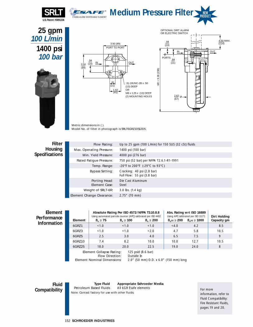
SCHROEDER INDUSTRIES152
FluidCompatibility
Type Fluid Appropriate Schroeder MediaPetroleum Based Fluids All 6GR Esafe elements
Note: Contact factory for use with other fluids.For more information, refer toFluid Compatibility:Fire Resistant Fluids,pages 19 and 20.
Absolute Rating Per ISO 4572/NFPA T3.10.8.8 Abs. Rating wrt ISO 16889 Using automated particle counter (APC) calibrated per ISO 4402 Using APC calibrated per ISO 11171 Dirt Holding
Element ßx ≥ 75 ßx ≥ 100 ßx ≥ 200 ßx(c) ≥ 200 ßx(c) ≥ 1000 Capacity gm
6GRZ1 <1.0 <1.0 <1.0 <4.0 4.2 8.5
6GRZ3 <1.0 <1.0 <2.0 4.7 5.8 10.5
6GRZ5 2.5 3.0 4.0 6.5 7.5 9
6GRZ10 7.4 8.2 10.0 10.0 12.7 10.5
6GRZ25 18.0 20.0 22.5 19.0 24.0 8
Element Collapse Rating: 125 psid (8.6 bar)Flow Direction: Outside In
Element Nominal Dimensions: 2.0” (50 mm) O.D. x 6.0” (150 mm) long
Flow Rating: Up to 25 gpm (100 L/min) for 150 SUS (32 cSt) fluids
Max. Operating Pressure: 1400 psi (100 bar)
Min. Yield Pressure: 4000 psi (276 bar)
Rated Fatigue Pressure: 750 psi (52 bar) per NFPA T2.6.1-R1-1991
Temp. Range: -20°F to 200°F (-29°C to 93°C)
Bypass Setting: Cracking: 40 psi (2.8 bar)Full Flow: 55 psi (3.8 bar)
Porting Head: Die Cast AluminumElement Case: Steel
Weight of SRLT-6R: 3.0 lbs. (1.4 kg)
Element Change Clearance: 2.75” (70 mm)
Filter Housing
Specifications
25 gpm100 L/min
1400 psi100 bar
Medium Pressure Filter
ElementPerformanceInformation
SRLT
Metric dimensions in ( ).Model No. of filter in photograph is SRLT6GRZ10S12D5.
4.50 MAX..94(24)
PORT TO PORT
1.62(41)
.31-18UNC-2B x .50 (13) DEEPORM8 x 1.25 x (13) DEEP(2) MOUNTING HOLES 2.62
(67)Ø
OPTIONAL DIRT ALARMOR ELECTRIC SWITCH
CPORTS
OUTIN
OUTIN
3.50 (89)
.81(21)
.94(24)3.50
(89)
(114)
6R =
9.3
8 (2
38)
.84(21)
STAND-ALONE DISPOSABLE ELEMENT
™™
U.S. Patent #5891336
NEWPRODUCT
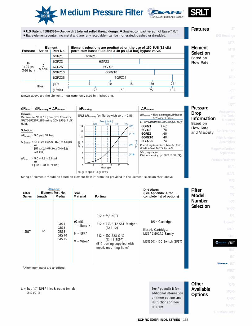
153SCHROEDER INDUSTRIES
FilterModelNumberSelection
OtherAvailableOptions
See Appendix B foradditional informationon these options andinstructions on how to order.
PressureDropInformationBased on Flow Rateand Viscosity
ElementSelectionBased on Flow Rate
Features� U.S. Patent #5891336—Unique dirt tolerant rolled thread design. � Smaller, compact version of EsafeTM RLT.� Esafe elements contain no metal and are fully recyclable—can be incinerated, crushed or shredded.
SRLT ∆Phousing for fluids with sp gr=0.86:
∆Pfilter = ∆Phousing + ∆Pelement ∆Phousing ∆Pelement
Exercise:Determine ∆P at 15 gpm (57 L/min) forSRLT6GRZ25P12D5 using 200 SUS (44 cSt)fluid.
Solution:
∆Phousing = 5.0 psi [.37 bar]
∆Pelement = 15 x .24 x (200÷150) = 4.8 psior
∆Pelement = [57 x (.24÷54.9) x (44÷32) = .34 bar]
∆Ptotal = 5.0 + 4.8 = 9.8 psior
∆Pelement = [.37 + .34 = .71 bar]
Sizing of elements should be based on element flow information provided in the Element Selection chart above.
sp gr = specific gravity
14
12
10
8
6
4
2
(1.0)
(0.75)
(0.5)
(0.25)
0 5 10 15 20 25Flow gpm
Flow (L/min)(25) (50) (75) (95)
∆P (b
ar)
∆P p
si
Element Element selections are predicated on the use of 150 SUS (32 cSt) Pressure Series Part No. petroleum based fluid and a 40 psi (2.8 bar) bypass valve.
6GRZ1 6GRZ1
6GRZ3 6GRZ3
6GRZ5 6GRZ5
6GRZ10 6GRZ10
6GRZ25 6GRZ25
Flowgpm 0 5 10 15 20 25
(L/min) 0 25 50 75 100
Shown above are the elements most commonly used in this housing.
To1400 psi(100 bar)
ZMedia
∆Pelement= flow x element ∆P factor x viscosity factor
El. ∆P factors @ 150 SUS (32 cSt):
6GRZ1 1.626GRZ3 .786GRZ5 .606GRZ10 .486GRZ25 .24
If working in units of bars & L/min,divide above factor by 54.9.
Viscosity factor:Divide viscosity by 150 SUS (32 cSt).
P12 = 3⁄4” NPTF
S12 = 11⁄16”-12 SAE Straight(SAE-12)
B12 = ISO 228 G-3⁄4(3⁄4 -14 BSPP)
(B12 porting supplied with metric mounting holes)
(Omit) = Buna N
H = EPR*
V = Viton*
6”
GRZ1GRZ3GRZ5GRZ10GRZ25
SRLT
D5 = Cartridge
Electric Cartridge:MS5AC/DC/LC Family
MS15DC= DC Switch (SPST)
SRLTMedium Pressure Filter
**Aluminum parts are anodized.
STAND-ALONE DISPOSABLE ELEMENT
™™
STAND-ALONE DISPOSABLE ELEMENT
™™ Dirt AlarmFilter Element Part No. Seal (See Appendix A for Series Length Media Material Porting complete list of options)
L = Two 1⁄4” NPTF inlet & outlet femaletest ports
NEWPRODUCT
ST
SKB Housings
MTA
MTB
GT
ZT
RT
RTD
RTI
KFT
LRT
BFT
Accessories for Tank-Mounted
Filters
Air Breathers
Filler StrainerAssemblies
Magnetic SuctionSeparators
Suction Strainers
PAF1
MAF1
MF2
TF1
TF3
KF3
WKF3
LF1
LF1—2"
MLF1
SRLT
SRLT
TRLT
RLT
RLT
WRLT
KF8
QF5
MQF5
QFD2
4QFD2
Filtration Carts
STAND-ALONE DISPOSABLE ELEMENT
™™
STAND-ALONE DISPOSABLE ELEMENT
™™

SCHROEDER INDUSTRIES154
FluidCompatibility
Type Fluid Appropriate Schroeder MediaPetroleum Based Fluids All Paper (E) and Synthetic (Z) media
High Water Content Z1, Z3, Z5, Z10, Z25Invert Emulsions Z10, Z25
Water Glycols Z3, Z5, Z10, Z25Phosphate Esters All Z media with EPR Seals
Skydrol Z3H.5, Z5H.5, Z10H.5 and Z25H.5Note: Contact factory regarding use of E Media in High Water Content, Invert Emulsion and Water Glycol Applications.
For more information, refer toFluid Compatibility:Fire Resistant Fluids,pages 19 and 20.
70 gpm270 L/min
800 psi55 bar
Medium Pressure FilterTRLT
Metric dimensions in ( ).Model No. of filter in photograph is TRLT8TZ10F16D5.
1.50
4.75(121)
1.38 IN OUT
3.50 (89)
OUTIN
(38)
(17.5)
(35)
8T =
12.
20 (
310)
13
T =
16.
92 (
430)
16T
= 2
0.81
(52
9)
Ø
(114)4.50 MAX.
(106)4.18
.69
(49)1.94
3.88(98)
OPTIONAL DIRT ALARMOR ELECTRIC SWITCH
.31-18UNC-2B x .50 (13) DP.ORM8 x 1.25 x (13) DP.(4) MOUNTING HOLES
Absolute Rating Per ISO 4572/NFPA T3.10.8.8 Abs. Rating wrt ISO 16889 Using automated particle counter (APC) calibrated per ISO 4402 Using APC calibrated per ISO 11171 Dirt Holding
Element ßx ≥ 75 ßx ≥ 100 ßx ≥ 200 ßx(c) ≥ 200 ßx(c) ≥ 1000 Capacity gm
8T3 6.8 7.5 10.0 N/A N/A 39
8T10 15.5 16.2 18.0 N/A N/A 32
8TZ1 <1.0 <1.0 <1.0 <4.0 4.2 51
8TZ3 <1.0 <1.0 <2.0 4.7 5.8 52
8TZ5 2.5 3.0 4.0 6.5 7.5 43
8TZ10 7.4 8.2 10.0 10.0 12.7 55
8TZ25 18.0 20.0 22.5 19.0 24.0 53
Element Collapse Rating: 150 psid (10 bar)Flow Direction: Outside In
Element Nominal Dimensions: 3.1” (80 mm) O.D. x 8.0” (205 mm) long
Flow Rating: Up to 70 gpm (270 L/min) for 150 SUS (32 cSt) fluids for P20, S20, & B20 portingUp to 50 gpm (190 L/min) for 150 SUS (32 cSt) fluids for P16, S16, F16, F20& B16 porting
Max. Operating Pressure: 800 psi (55 bar)
Min. Yield Pressure: 2400 psi (165 bar)
Rated Fatigue Pressure: 415 psi (29 bar), per NFPA T2.6.1-R1-1991
Temp. Range: -20°F to 225°F (-29°C to 107°C)
Bypass Setting: Cracking: 50 psi (3 bar) for all portingFull Flow: 45 psi (3 bar) for P20 & S20 portingFull Flow: 68 psi (5 bar) for P16, S16, F16 & F20 porting
Porting Head: Die Cast AluminumElement Case: Steel
Weight of TRLT-8T: 6.7 lbs. (3.0 kg)
Element Change Clearance: 2.75” (70 mm)
Filter Housing
Specifications
ElementPerformanceInformation
U.S. Patent #5891336

FilterModelNumberSelection
OtherAvailableOptions
See Appendix B foradditional informationon these options andinstructions on how to order.
PressureDropInformationBased on Flow Rateand Viscosity
ElementSelectionBased on Flow Rate
Features
155SCHROEDER INDUSTRIES
� U.S. Patent #5891336—Unique dirt tolerant rolled thread design. � Meets HF3 automotive standard. � Quick and easy element changeouts.
TRLT ∆Phousing for fluids with sp gr = 0.86:
∆Pfilter = ∆Phousing + ∆Pelement ∆Phousing ∆Pelement
Exercise:Determine ∆P at 40 gpm (150 L/min) forTRLT8TZ10S16D5 using 200 SUS (44 cSt)fluid.
Solution:
∆Phousing = 5.5 psi [.40 bar]
∆Pelement = 40 x .11 x (200÷150) = 5.9 psior
∆Pelement = [150 x (.11÷54.9) x (44÷32) = .41 bar]
∆Ptotal = 5.5 + 5.9 = 11.4 psior
∆Pelement = [.40 + .41 = .81 bar]
Sizing of elements should be based on element flow information provided in the Element Selection chart above.
sp gr = specific gravity
(0.50)
(0.75)
(0.25)
14
12
10
8
6
4
2
0 0 10 20 30 40 50 60 70
Flow gpm
Flow (L/min)(50) (100) (150) (200) (250)
∆P (b
ar)
∆P p
si
SIZE 1
6 PORTIN
G
SIZE 2
0 PORT
ING
To800 psi(55 bar)
∆Pelement= flow x element ∆P factor x viscosity factor
El. ∆P factors @ 150 SUS (32 cSt):
8T3 .258T10 .098T25 .028TZ1 .378TZ3 .218TZ5 .138TZ10 .118TZ25 .08
If working in units of bars & L/min,divide above factor by 54.9.
Viscosity factor:Divide viscosity by 150 SUS (32 cSt).
TRLTMedium Pressure Filter
P16 = 1” NPTFP20 = 11⁄4” NPTF
S16 = 15⁄16”-12 SAE Straight(SAE-16)
S20 = 15⁄8”-12 SAE Straight(SAE-20)
F16 = 1” SAE J518 4-BoltFlange Code 61
F20 = 11⁄4” SAE J518 4-BoltFlange Code 61
B16 = ISO 228 G-1(1-11 BSPP)
B20 = ISO 228 G-11⁄4(11⁄4-11 BSPP)
(B16 & B20 porting suppliedwith metric mounting holes)
(Omit) = Buna N
H = EPR**
V = Viton**
8”
13”
16”
T3*T10*
TZ1TZ3TZ5TZ10TZ25
TW
TRLT
D5 = Cartridge
Electric Cartridge:MS5AC/DC/LC Family
**Only available with Buna N seals.**Aluminum parts are anodized.
Dirt AlarmFilter Element Part No. Seal (See Appendix A for Series Length Media Material Porting complete list of options)
L = Two 1⁄4” NPTF inlet & outlet femaletest ports
See RLT or ContactFactory for HF3 Option
See RLT or ContactFactory for HF3 Option
Element Element selections are predicated on the use of 150 SUS (32 cSt) Pressure Series Part No. petroleum based fluid and a 40 psi (2.8 bar) bypass valve.
E 8T3 8T3 See RLT or Contact Factory for H3 OptionMedia 8T10 8T10
8TZ1 8TZ1 See RLT or Contact Factory for HF3 Option
Z8TZ3 8TZ3 See RLT or Contact Factory for HF3 Option
Media 8TZ5 8TZ58TZ10 8TZ108TZ25 8TZ25
Flowgpm 0 10 20 30 40 50 60 70
(L/min) 0 50 100 150 200 270
Shown above are the elements most commonly used in this housing. ���� requires size 20 porting
ST
SKB Housings
MTA
MTB
GT
ZT
RT
RTD
RTI
KFT
LRT
BFT
Accessories for Tank-Mounted
Filters
Air Breathers
Filler StrainerAssemblies
Magnetic SuctionSeparators
Suction Strainers
PAF1
MAF1
MF2
TF1
TF3
KF3
WKF3
LF1
LF1—2"
MLF1
SRLT
SRLT
TRLT
RLT
RLT
WRLT
KF8
QF5
MQF5
QFD2
4QFD2
Filtration Carts
STAND-ALONE DISPOSABLE ELEMENT
™™
STAND-ALONE DISPOSABLE ELEMENT
™™

Flow Rating: Up to 70 gpm (270 L/min) for 150 SUS (32 cSt) fluids for P20, S20, & B20 portingUp to 50 gpm (190 L/min) for 150 SUS (32 cSt) fluids for P16, S16, F16, F20& B16 porting
Max. Operating Pressure: 800 psi (55 bar)
Min. Yield Pressure: 2400 psi (165 bar)
Rated Fatigue Pressure: 415 psi (29 bar), per NFPA T2.6.1-R1-1991
Temp. Range: -20°F to 225°F (-29°C to 107°C)
Bypass Setting: Cracking: 40 psi (2.8 bar) for all portingFull Flow: 57 psi (3.9 bar) for P20 & S20 portingFull Flow: 75 psi (5.2 bar) for P16, S16, F16 & F20 porting
Porting Head: Die Cast AluminumElement Case: Steel
Weight of RLT-9V: 6.7 lbs. (3.0 kg)Weight of RLT-14V: 8.0 lbs. (3.6 kg)
Element Change Clearance: 9V & 14V: 2.75” (70 mm)
Filter Housing
Specifications
70 gpm270 L/min
800 psi55 bar
Medium Pressure Filter
ElementPerformanceInformation
156
RLT
Metric dimensions in ( ).Model No. of filter in photograph is RLT9VZ10S16D5.
1.50
4.75 (121)
1.38 IN OUT
3.50 (89)
OUTIN
(38)
(17.5)
(35)
9V =
13.
53 (
344)
14
V =
18.
53 (
471)
Ø
(114)4.50 MAX.
(106)4.18
.69
(49)1.94
3.88(98)
OPTIONAL DIRT ALARMOR ELECTRIC SWITCH
.31-18UNC-2B x .50 (13) DP.ORM8 x 1.25 x (13) DP.(4) MOUNTING HOLES
FluidCompatibility
Type Fluid Appropriate Schroeder MediaPetroleum Based Fluids All Paper (E) and Synthetic (Z) media
High Water Content Z1, Z3, Z5, Z10, Z25Invert Emulsions Z10, Z25
Water Glycols Z3, Z5, Z10, Z25Phosphate Esters All Z media with EPR Seals
Skydrol Z3H.5, Z5H.5, Z10H.5 and Z25H.5Note: Contact factory regarding use of E Media in High Water Content, Invert Emulsion and Water Glycol Applications.
For more information, refer toFluid Compatibility:Fire Resistant Fluids,pages 19 and 20.
SCHROEDER INDUSTRIES
Absolute Rating Per ISO 4572/NFPA T3.10.8.8 Abs. Rating wrt ISO 16889 Using automated particle counter (APC) calibrated per ISO 4402 Using APC calibrated per ISO 11171 Dirt Holding
Element ßx ≥ 75 ßx ≥ 100 ßx ≥ 200 ßx(c) ≥ 200 ßx(c) ≥ 1000 Capacity gm
9V3/14V3 6.8 7.5 10.0 N/A N/A 25/38
9V10/14V10 15.5 16.2 18.0 N/A N/A 12/25
9VZ1/14VZ1 <1.0 <1.0 <1.0 <4.0 4.2 55/102
9VZ3/14VZ3 <1.0 <1.0 <2.0 4.7 5.8 57/105
9VZ5/14VZ5 2.5 3.0 4.0 6.5 7.5 45/83
9VZ10/14VZ10 7.4 8.2 10.0 10.0 12.7 52/104
9VZ25/14VZ25 18.0 20.0 22.5 19.0 24.0 48/94
Element Collapse Rating: 150 psid (10 bar)500 psid (34.5 bar) for hydrostatic high crush (9V5Z10 element) version
Flow Direction: Outside InElement Nominal Dimensions: 9V: 3.0” (75 mm) O.D. x 9.5” (240 mm) long
14V: 3.0” (75 mm) O.D. x 14.5” (370 mm) long
U.S. Patent #5891336

FilterModelNumberSelection
OtherAvailableOptions
See Appendix B foradditional informationon these options andinstructions on how to order.
PressureDropInformationBased on Flow Rateand Viscosity
ElementSelectionBased on Flow Rate
Features� U.S. Patent #5891336—Unique dirt tolerant rolled thread design. � Durable, lightweight, compactdesign. � Quick and easy element changeouts.
RLT ∆Phousing for fluids with sp gr = 0.86:
∆Pfilter = ∆Phousing + ∆Pelement ∆Phousing ∆Pelement
Exercise:Determine ∆P at 40 gpm (150 L/min) forRLT9VZ5S16D5 using 200 SUS (44 cSt) fluid.
Solution:
∆Phousing = 5.5 psi [.35 bar]
∆Pelement = 40 x .13 x (200÷150) = 6.9 psior
∆Pelement = [150 x (.13÷54.9) x (44÷32) = .49 bar]
∆Ptotal = 5.5 + 6.9 = 12.4 psior
∆Pelement = [.35 + .49 = .84 bar]
Sizing of elements should be based on element flow information provided in the Element Selection chart above.
sp gr = specific gravity
(0.50)
(0.75)
(0.25)
14
12
10
8
6
4
2
0 0 10 20 30 40 50 60 70
Flow gpm
Flow (L/min)(50) (150) (250)
∆P (b
ar)
∆P p
si
SIZE 1
6 PORTIN
G
SIZE 2
0 PORT
ING
To800 psi(55 bar)
∆Pelement= flow x element ∆P factor x viscosity factor
El. ∆P factors @ 150 SUS (32 cSt):9V 14V
9V3 .32 14V3 .199V10 .24 14V10 .159VZ1 .34 14VZ1 .219VZ3 .21 14VZ3 .179VZ5 .13 14VZ5 .099VZ10 .11 14VZ10 .089VZ25 .06 14VZ25 .05If working in units of bars & L/min,divide above factor by 54.9.
Viscosity factor:Divide viscosity by 150 SUS (32 cSt).
P16 = 1” NPTFP20 = 11⁄4” NPTF
S16 = 15⁄16”-12 SAE Straight(SAE-16)
S20 = 15⁄8”-12 SAE Straight(SAE-20)
F16 = 1” SAE J518 4-BoltFlange Code 61
F20 = 11⁄4” SAE J518 4-BoltFlange Code 61
B16 = ISO 228 G-1(1-11 BSPP)
B20 = ISO 228 G-11⁄4(11⁄4-11 BSPP)
(B16 & B20 porting suppliedwith metric mounting holes)
(Omit) = Buna N
H = EPR**
V = Viton**
9”
14”
**Only available with Buna N seals.**Aluminum parts are anodized.
V3*V10*
VZ1VZ3VZ5VZ10VZ25
VW
RLT
RLTN 9” V5Z10
D5 = Cartridge
Electric Cartridge:MS5AC/DC/LC Family
MS15DC= DC Switch (SPST)
RLTMedium Pressure Filter
157SCHROEDER INDUSTRIES
Dirt AlarmFilter Element Part No. Seal (See Appendix A for Series Length Media Material Porting complete list of options)
L = Two 1⁄4” NPTF inlet & outlet femaletest ports
ST
SKB Housings
MTA
MTB
GT
ZT
RT
RTD
RTI
KFT
LRT
BFT
Accessories for Tank-Mounted
Filters
Air Breathers
Filler StrainerAssemblies
Magnetic SuctionSeparators
Suction Strainers
PAF1
MAF1
MF2
TF1
TF3
KF3
WKF3
LF1
LF1—2"
MLF1
SRLT
SRLT
TRLT
RLT
RLT
WRLT
KF8
QF5
MQF5
QFD2
4QFD2
Filtration Carts
STAND-ALONE DISPOSABLE ELEMENT
™™
STAND-ALONE DISPOSABLE ELEMENT
™™
Element Element selections are predicated on the use of 150 SUS (32 cSt) Pressure Series Part No. petroleum based fluid and a 40 psi (2.8 bar) bypass valve.
9V3 & 14V3 9V3 14V3 Contact FactoryE Media9V10 & 14V10 9V10 14V10 Contact Factory9VZ1 & 14VZ1 9VZ1 14VZ1 Contact Factory
Z9VZ3 & 14VZ3 9VZ3 14VZ3 Contact Factory
Media 9VZ5 & 14VZ5 9VZ5 14VZ5
9VZ10 & 14VZ10 9VZ10 & 14VZ109VZ25 & 14VZ25 9VZ25 & 14VZ25
Flowgpm 0 10 20 30 40 50 60 70
(L/min) 0 50 100 150 200 270
Shown above are the elements most commonly used in this housing. ���� requires size 20 porting

SCHROEDER INDUSTRIES158
Flow Rating: Up to 70 gpm (270 L/min) for 150 SUS (32 cSt) fluids for P20, S20, & B20 portingUp to 50 gpm (190 L/min) for 150 SUS (32 cSt) fluids for P16, S16, F16, F20& B16 porting
Max. Operating Pressure: 800 psi (55 bar)
Min. Yield Pressure: 2400 psi (165 bar)
Rated Fatigue Pressure: 415 psi (29 bar), per NFPA T2.6.1-R1-1991
Temp. Range: -20°F to 200°F (-29°C to 93°C)
Bypass Setting: Cracking: 40 psi (2.8 bar) for all portingFull Flow: 57 psi (3.9 bar) for P20 & S20 portingFull Flow: 75 psi (5.2 bar) for P16, S16, F16 & F20 porting
Porting Head: Die Cast AluminumElement Case: Steel
Weight of RLT-9V: 6.7 lbs. (3.0 kg)
Element Change Clearance: 2.75” (70 mm)
Filter Housing
Specifications
70 gpm270 L/min
800 psi55 bar
ElementPerformanceInformation
RLT
Metric dimensions in ( ).Model No. of filter in photograph is RLT9GVZ10S16D5.
1.50
4.75 (121)
1.38 IN OUT
3.50 (89)
OUTIN
(38)
(17.5)
(35)
9V =
13.
53 (
344)
14
V =
18.
53 (
471)
Ø
(114)4.50 MAX.
(106)4.18
.69
(49)1.94
3.88(98)
OPTIONAL DIRT ALARMOR ELECTRIC SWITCH
.31-18UNC-2B x .50 (13) DP.ORM8 x 1.25 x (13) DP.(4) MOUNTING HOLES
FluidCompatibility
Type Fluid Appropriate Schroeder MediaPetroleum Based Fluids All 9GV Esafe elements
Note: Contact factory for use with other fluids.For more information, refer toFluid Compatibility:Fire Resistant Fluids,pages 19 and 20.
Absolute Rating Per ISO 4572/NFPA T3.10.8.8 Abs. Rating wrt ISO 16889 Using automated particle counter (APC) calibrated per ISO 4402 Using APC calibrated per ISO 11171 Dirt Holding
Element ßx ≥ 75 ßx ≥ 100 ßx ≥ 200 ßx(c) ≥ 200 ßx(c) ≥ 1000 Capacity gm
9GVZ1 <1.0 <1.0 <1.0 <4.0 4.2 45
9GVZ3 <1.0 <1.0 <2.0 4.7 5.8 44.5
9GVZ5 2.5 3.0 4.0 6.5 7.5 37
9GVZ10 7.4 8.2 10.0 10.0 12.7 46
9GVZ25 18.0 20.0 22.5 19.0 24.0 27
Element Collapse Rating: 125 psid (8.6 bar)Flow Direction: Outside In
Element Nominal Dimensions: 9V: 3.0” (75 mm) O.D. x 9.5” (240 mm) long
Medium Pressure FilterSTAND-ALONE DISPOSABLE ELEMENT
™™
U.S. Patent #5891336
NEWPRODUCT
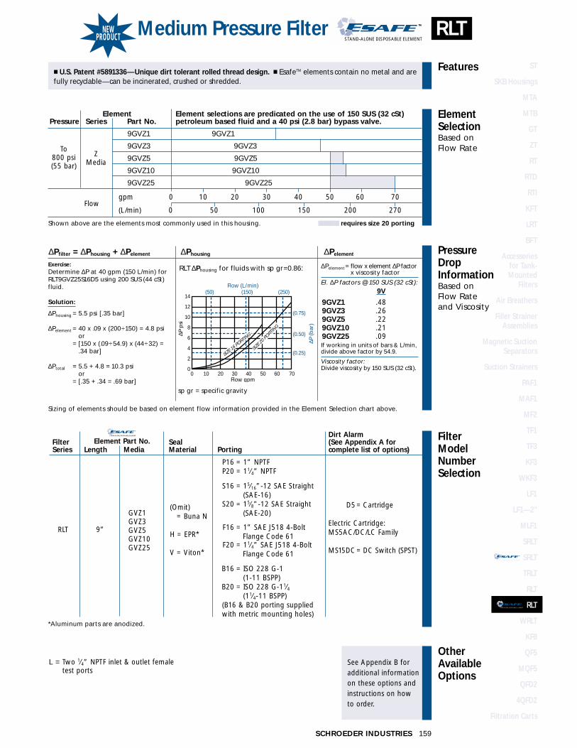
159SCHROEDER INDUSTRIES
FilterModelNumberSelection
OtherAvailableOptions
See Appendix B foradditional informationon these options andinstructions on how to order.
PressureDropInformationBased on Flow Rateand Viscosity
ElementSelectionBased on Flow Rate
Features� U.S. Patent #5891336—Unique dirt tolerant rolled thread design. � EsafeTM elements contain no metal and arefully recyclable—can be incinerated, crushed or shredded.
∆Pfilter = ∆Phousing + ∆Pelement ∆Phousing ∆Pelement
Exercise:Determine ∆P at 40 gpm (150 L/min) forRLT9GVZ25S16D5 using 200 SUS (44 cSt)fluid.
Solution:
∆Phousing = 5.5 psi [.35 bar]
∆Pelement = 40 x .09 x (200÷150) = 4.8 psior
∆Pelement = [150 x (.09÷54.9) x (44÷32) = .34 bar]
∆Ptotal = 5.5 + 4.8 = 10.3 psior
∆Pelement = [.35 + .34 = .69 bar]
Sizing of elements should be based on element flow information provided in the Element Selection chart above.
sp gr = specific gravity
(0.50)
(0.75)
(0.25)
14
12
10
8
6
4
2
0 0 10 20 30 40 50 60 70
Flow gpm
Flow (L/min)(50) (150) (250)
∆P (b
ar)
∆P p
si
SIZE 1
6 PORTIN
G
SIZE 2
0 PORT
ING
Element Element selections are predicated on the use of 150 SUS (32 cSt) Pressure Series Part No. petroleum based fluid and a 40 psi (2.8 bar) bypass valve.
9GVZ1 9GVZ1
9GVZ3 9GVZ3
9GVZ5 9GVZ5
9GVZ10 9GVZ10
9GVZ25 9GVZ25
Flowgpm 0 10 20 30 40 50 60 70
(L/min) 0 50 100 150 200 270
Shown above are the elements most commonly used in this housing. ���� requires size 20 porting
To800 psi(55 bar)
ZMedia
∆Pelement= flow x element ∆P factor x viscosity factor
El. ∆P factors @ 150 SUS (32 cSt):9V
9GVZ1 .489GVZ3 .269GVZ5 .229GVZ10 .219GVZ25 .09If working in units of bars & L/min,divide above factor by 54.9.
Viscosity factor:Divide viscosity by 150 SUS (32 cSt).
P16 = 1” NPTFP20 = 11⁄4” NPTF
S16 = 15⁄16”-12 SAE Straight(SAE-16)
S20 = 15⁄8”-12 SAE Straight(SAE-20)
F16 = 1” SAE J518 4-BoltFlange Code 61
F20 = 11⁄4” SAE J518 4-BoltFlange Code 61
B16 = ISO 228 G-1(1-11 BSPP)
B20 = ISO 228 G-11⁄4(11⁄4-11 BSPP)
(B16 & B20 porting suppliedwith metric mounting holes)
(Omit) = Buna N
H = EPR*
V = Viton*
9”
*Aluminum parts are anodized.
GVZ1GVZ3GVZ5GVZ10GVZ25
RLT
D5 = Cartridge
Electric Cartridge:MS5AC/DC/LC Family
MS15DC= DC Switch (SPST)
RLTMedium Pressure FilterSTAND-ALONE DISPOSABLE ELEMENT
™™
RLT ∆Phousing for fluids with sp gr=0.86:
STAND-ALONE DISPOSABLE ELEMENT
™™
Dirt AlarmFilter Element Part No. Seal (See Appendix A for Series Length Media Material Porting complete list of options)
L = Two 1⁄4” NPTF inlet & outlet femaletest ports
NEWPRODUCT
ST
SKB Housings
MTA
MTB
GT
ZT
RT
RTD
RTI
KFT
LRT
BFT
Accessories for Tank-Mounted
Filters
Air Breathers
Filler StrainerAssemblies
Magnetic SuctionSeparators
Suction Strainers
PAF1
MAF1
MF2
TF1
TF3
KF3
WKF3
LF1
LF1—2"
MLF1
SRLT
SRLT
TRLT
RLT
RLT
WRLT
KF8
QF5
MQF5
QFD2
4QFD2
Filtration Carts
STAND-ALONE DISPOSABLE ELEMENT
™™
STAND-ALONE DISPOSABLE ELEMENT
™™

Flow Rating: Up to 70 gpm (270 L/min) for 150 SUS (32 cSt) fluids
Max. Operating Pressure: 800 psi (55 bar)
Min. Yield Pressure: 2400 psi (165 bar)
Rated Fatigue Pressure: 415 psi (29 bar), per NFPA T2.6.1-R1-1991
Temp. Range: -20°F to 225°F (-29°C to 107°C)
Bypass Setting: Cracking: 40 psi (2.8 bar)Full Flow: 57 psi (3.9 bar)
Porting Head: Anodized Cast AluminumElement Case: Steel with protective coating
Weight of WRLT-9V: 6.25 lbs. (2.8 kg)
Element Change Clearance: 2.75” (70 mm)
Filter Housing
Specifications
70 gpm270 L/min
800 psi55 bar
Medium Pressure (Water Service) Filter
ElementPerformanceInformation
160
WRLT
Metric dimensions in ( ).Model No. of filter in photograph is WRLT9VM150S16D5.
1.50
4.75 (121)
1.38 IN OUT
3.50 (89)
OUTIN
(38)
(17.5)
(35)
9V =
13.
53 (
344)
14
V =
18.
53 (
471)
Ø
(114)4.50 MAX.
(106)4.18
.69
(49)1.94
3.88(98)
OPTIONAL DIRT ALARMOR ELECTRIC SWITCH
.31-18UNC-2B x .50 (13) DP.ORM8 x 1.25 x (13) DP.(4) MOUNTING HOLES
FluidCompatibility
Type Fluid Appropriate Schroeder MediaWater All Metal (M) elements For more
information, refer toFluid Compatibility:Fire Resistant Fluids,pages 19 and 20.
SCHROEDER INDUSTRIES
NEWPRODUCT
Nominal RatingElement Metal Mesh
(micron)
9VM150 150
9VM260 260
9VMX150 150
9VMX260 260
Element Collapse Rating: 150 psid (10 bar)Flow Direction: Outside In
Element Nominal Dimensions: 3.0” (75 mm) O.D. x 9.5” (240 mm) long

ST
SKB Housings
MTA
MTB
GT
ZT
RT
RTD
RTI
KFT
LRT
BFT
Accessories for Tank-Mounted
Filters
Air Breathers
Filler StrainerAssemblies
Magnetic SuctionSeparators
Suction Strainers
PAF1
MAF1
MF2
TF1
TF3
KF3
WKF3
LF1
LF1—2"
MLF1
SRLT
SRLT
TRLT
RLT
RLT
WRLT
KF8
QF5
MQF5
QFD2
4QFD2
Filtration Carts
STAND-ALONE DISPOSABLE ELEMENT
™™
STAND-ALONE DISPOSABLE ELEMENT
™™
STAND-ALONE DISPOSABLE ELEMENT
™™
STAND-ALONE DISPOSABLE ELEMENT
™™
Element Element selections are predicated on the use of 150 SUS (32 cSt) Pressure Series Part No. petroleum based fluid and a 40 psi (2.8 bar) bypass valve.
9VM150 9VM1509VM260 9VM260M9VMX150 9VMX150Media
9VMX260 9VMX260
Flowgpm 0 10 20 30 40 50 60 70
(L/min) 0 50 100 150 200 270
Shown above are the elements most commonly used in this housing.
FilterModelNumberSelection
OtherAvailableOptions
See Appendix B foradditional informationon these options andinstructions on how to order.
PressureDropInformationBased on Flow Rateand Viscosity
ElementSelectionBased on Flow Rate
Features� U.S. Patent #5891336. � Unique dirt tolerant rolled thread design. � Durable, lightweight, compactdesign. � Quick and easy element changeouts.
WRLT ∆Phousing for water:
∆Pfilter = ∆Phousing + ∆Pelement ∆Phousing ∆Pelement
Exercise:Determine ∆P at 50 gpm (190 L/min) forWRLT9VM150P20 using water.
Solution:
∆Phousing = 7.0 psi [.48 bar]
∆Pelement = 50 x .03 = 1.5 psior
∆Pelement = [190 x (.03÷54.9) = .10 bar]
∆Ptotal = 7.0 + 1.5 = 8.5 psior
∆Pelement = [.48 + .10 = .58 bar]
Sizing of elements should be based on element flow information provided in the Element Selection chart above.
sp gr = specific gravity
(0.50)
(0.75)
(0.25)
14
12
10
8
6
4
2
0 0 10 20 30 40 50 60 70
Flow gpm
Flow (L/min)(50) (150) (250)
∆P (b
ar)
∆P p
si
To800 psi(55 bar)
∆Pelement= flow x element ∆P factor x viscosity factor
El. ∆P factors @ 150 SUS (32 cSt):
9VM150 .039VM260 .039VMX150 .039VMX260 .03If working in units of bars & L/min,divide above factor by 54.9.
Viscosity factor:Divide viscosity by 150 SUS (32 cSt).
P20 = 11⁄4” NPTF
S20 = 15⁄8”-12 SAE Straight
(Omit) = Buna N
H = EPR
V = Viton
**Only available with Buna N seals.**Aluminum parts are anodized.
VM150VM260
WRLT 9”
WRLTN9”
VMX150(Non-
VMX260Bypass)
D5 = Cartridge
Electric Cartridge:MS5AC = AC onlyMS5DC = DC onlyMS5LC = AC & DC
(Low current application)
WRLTMedium Pressure (Water Service) Filter
161SCHROEDER INDUSTRIES
Dirt AlarmFilter Element Part No. Seal (See Appendix A for Series Length Media Material Porting complete list of options)
L = Two 1⁄4” NPTF inlet & outlet femaletest ports
NEWPRODUCT
ST
SKB Housings
MTA
MTB
GT
ZT
RT
RTD
RTI
KFT
LRT
BFT
Accessories for Tank-Mounted
Filters
Air Breathers
Filler StrainerAssemblies
Magnetic SuctionSeparators
Suction Strainers
PAF1
MAF1
MF2
TF1
TF3
KF3
WKF3
LF1
LF1—2"
MLF1
SRLT
SRLT
TRLT
RLT
RLT
WRLT
KF8
QF5
MQF5
QFD2
4QFD2
Filtration Carts

Absolute Rating Per ISO 4572/NFPA T3.10.8.8 Abs. Rating wrt ISO 16889 Using automated particle counter (APC) calibrated per ISO 4402 Using APC calibrated per ISO 11171 Dirt Holding
Element ßx ≥ 75 ßx ≥ 100 ßx ≥ 200 ßx(c) ≥ 200 ßx(c) ≥ 1000 Capacity gm
K3 6.8 7.5 10.0 N/A N/A 54
K10 15.5 16.2 18.0 N/A N/A 44
KZ1 <1.0 <1.0 <1.0 <4.0 4.2 112
KZ3 <1.0 <1.0 <2.0 4.7 5.8 115
KZ5 2.5 3.0 4.0 6.5 7.5 86
KZ10 7.4 8.2 10.0 10.0 12.7 108
KZ25 18.0 20.0 22.5 19.0 24.0 93
Element Collapse Rating: 150 psid (10 bar)Flow Direction: Outside In
Element Nominal Dimensions: 4.0” (100 mm) O.D. x 9.0” (230 mm) long
Flow Rating: Up to 100 gpm (380 L/min) for 150 SUS (32 cSt) fluids
Max. Operating Pressure: 800 psi (55 bar)
Min. Yield Pressure: 2600 psi (179 bar)
Rated Fatigue Pressure: 500 psi (35 bar), per NFPA T2.6.1-1974
Temp. Range: -20°F to 225°F (-29°C to 107°C)
Bypass Setting: Cracking: 40 psi (2.8 bar)Full Flow: 61 psi (4.2 bar)
Porting Head: Grey Cast IronElement Case: Steel
Weight of KF8-1K: 23.2 lbs. (10.5 kg)
Element Change Clearance: 2.00” (51 mm)
Filter Housing
Specifications
100 gpm380 L/min
800 psi55 bar
Medium Pressure Filter
ElementPerformanceInformation
KF8
Metric dimensions in ( ).Model No. of filter in photograph is KF81KZ10SD5.
(51)2.001.75
(44)
(48) .62(16)
4.69 (119)
1K =
14.
18(3
60)
.38-16UNC-2B x .50 (13) DP.ORM10 x 1.5 x (13) DP.(2) MOUNTING HOLES
5.62(143)
6.25 (159)PORT TO PORT
(114)
OPTIONAL DIRT ALARMOR ELECTRIC SWITCH
Ø
OUT IN
4.50 MAX
1.88
FluidCompatibility
Type Fluid Appropriate Schroeder MediaPetroleum Based Fluids All Paper (E) and Synthetic (Z) Media
High Water Content Z1, Z3, Z5, Z10, Z25Invert Emulsions Z10, Z25
Water Glycols Z3, Z5, Z10, Z25Phosphate Esters All Z Media with EPR Seals, K3H and K10H E Media
Skydrol Z3H.5, Z5H.5, Z10H.5, Z25H.5 and WH.5 Note: Contact factory regarding use of E Media in High Water Content, Invert Emulsion and Water Glycol Applications.
For more information, refer toFluid Compatibility:Fire Resistant Fluids,pages 19 and 20.
SCHROEDER INDUSTRIES162
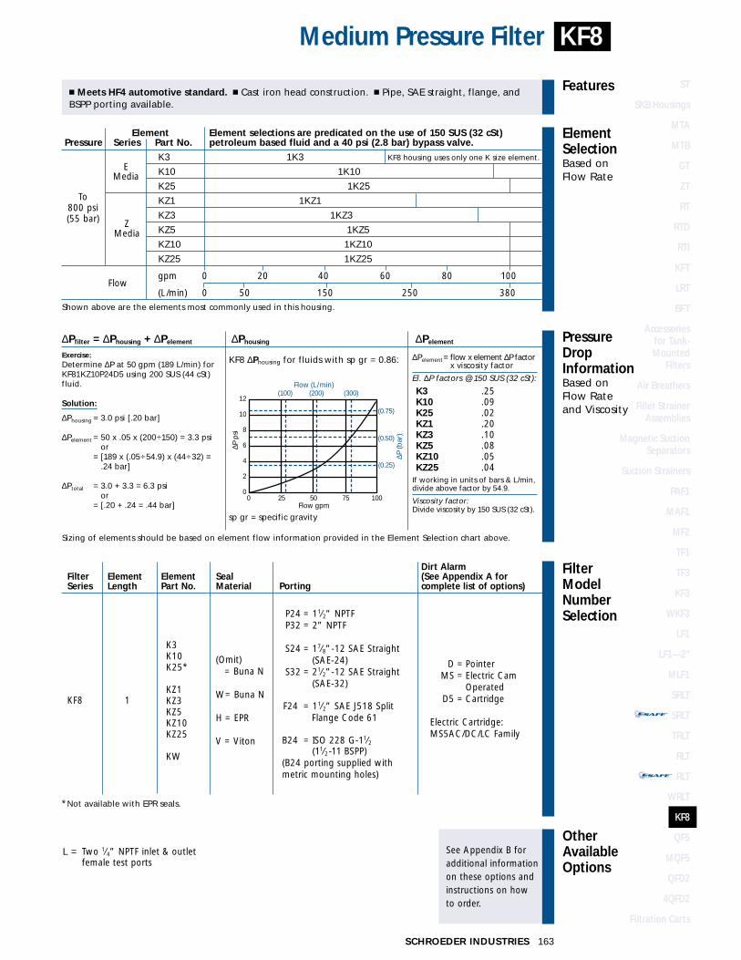
STAND-ALONE DISPOSABLE ELEMENT
™™
STAND-ALONE DISPOSABLE ELEMENT
™™
FilterModelNumberSelection
OtherAvailableOptions
See Appendix B foradditional informationon these options andinstructions on how to order.
PressureDropInformationBased on Flow Rateand Viscosity
ElementSelectionBased on Flow Rate
Features
Medium Pressure Filter
� Meets HF4 automotive standard. � Cast iron head construction. � Pipe, SAE straight, flange, andBSPP porting available.
KF8 ∆Phousing for fluids with sp gr = 0.86:
∆Pfilter = ∆Phousing + ∆Pelement ∆Phousing ∆Pelement
Exercise:Determine ∆P at 50 gpm (189 L/min) forKF81KZ10P24D5 using 200 SUS (44 cSt)fluid.
Solution:
∆Phousing = 3.0 psi [.20 bar]
∆Pelement = 50 x .05 x (200÷150) = 3.3 psior
∆Pelement = [189 x (.05÷54.9) x (44÷32) = .24 bar]
∆Ptotal = 3.0 + 3.3 = 6.3 psior
∆Pelement = [.20 + .24 = .44 bar]
Sizing of elements should be based on element flow information provided in the Element Selection chart above.
sp gr = specific gravity
Element Element selections are predicated on the use of 150 SUS (32 cSt) Pressure Series Part No. petroleum based fluid and a 40 psi (2.8 bar) bypass valve.
EK3 1K3
Media K10 1K10
K25 1K25
KZ1 1KZ1
KZ3 1KZ3Z
KZ5 1KZ5MediaKZ10 1KZ10
KZ25 1KZ25
Flowgpm 0 20 40 60 80 100
(L/min) 0 50 150 250 380Shown above are the elements most commonly used in this housing. KF8 housing uses only one K size element.
To800 psi(55 bar)
∆Pelement= flow x element ∆P factor x viscosity factor
El. ∆P factors @ 150 SUS (32 cSt):
K3 .25K10 .09K25 .02KZ1 .20KZ3 .10KZ5 .08KZ10 .05KZ25 .04
If working in units of bars & L/min,divide above factor by 54.9.
Viscosity factor:Divide viscosity by 150 SUS (32 cSt).
L = Two 1⁄4” NPTF inlet & outlet female test ports
P24 = 11⁄2” NPTFP32 = 2” NPTF
S24 = 17⁄8”-12 SAE Straight(SAE-24)
S32 = 21⁄2”-12 SAE Straight(SAE-32)
F24 = 11⁄2” SAE J518 Split Flange Code 61
B24 = ISO 228 G-11⁄2(11⁄2-11 BSPP)
(B24 porting supplied withmetric mounting holes)
(Omit) = Buna N
W= Buna N
H = EPR
V = Viton
1
*Not available with EPR seals.
K3K10K25*
KZ1KZ3KZ5KZ10KZ25
KW
KF8
D = PointerMS = Electric Cam
OperatedD5 = Cartridge
Electric Cartridge:MS5AC/DC/LC Family
KF8
163SCHROEDER INDUSTRIES
(0.25)
(100) (200)12
10
8
6
4
2
0
(0.75)
(0.50)
0 25 50 75 100Flow gpm
Flow (L/min)(300)
∆P (b
ar)
∆P p
si
Dirt AlarmFilter Element Element Seal (See Appendix A for Series Length Part No. Material Porting complete list of options)
ST
SKB Housings
MTA
MTB
GT
ZT
RT
RTD
RTI
KFT
LRT
BFT
Accessories for Tank-Mounted
Filters
Air Breathers
Filler StrainerAssemblies
Magnetic SuctionSeparators
Suction Strainers
PAF1
MAF1
MF2
TF1
TF3
KF3
WKF3
LF1
LF1—2"
MLF1
SRLT
SRLT
TRLT
RLT
RLT
WRLT
KF8
QF5
MQF5
QFD2
4QFD2
Filtration Carts
KF8 housing uses only one K size element.

Flow Rating: Up to 250 gpm (950 L/min) for 150 SUS (32 cSt) fluids
Max. Operating Pressure: 500 psi (35 bar)
Min. Yield Pressure: Contact factory
Rated Fatigue Pressure: Filter not designed for cyclic pressure applications
Temp. Range: -20°F to 225°F (-29°C to 107°C)
Bypass Setting: Cracking: 15 psi (1 bar), 30 psi (2 bar), or 50 psi (3.5 bar)—specify in model no.Full Flow: 69 psi (5 bar)
Porting Base & Cap: AluminumElement Case: Aluminum
Weight of QF5-16Q: 86.0 lbs. (39.0 kg)Weight of QF5-39Q: 105.0 lbs. (47.6 kg)
Element Change Clearance: 16Q 15.00” (380 mm)39Q 37.00” (940 mm)
Filter Housing
Specifications
250 gpm950 L/min
500 psi35 bar
Base-Ported Filter
ElementPerformanceInformation
QF5
Metric dimensions in ( ).Model No. of filter in photograph is QF539QZ10P3230.
US
Ø7.00(178)
39Q
= 5
3.50
(13
53)
16Q
= 3
1.75
(79
7)
3.00(76)
9.12(232)
4.88(124)
9.75(248)
10.50 (267) SAE 4-BOLT FLG. PORTS10.69 (272) PIPE & STR.THD. PORTS
.56 (14) Ø THRU(2) MOUNTING HOLES
OUTIN
DRAIN PLUG
IN
OUT
4.50 MAX.(114)
D
DRAIN PLUG
OPTIONAL DIRT ALARMOR ELECTRIC SWITCH
2.25(57)
2.25(57)
FluidCompatibility
Type Fluid Appropriate Schroeder MediaPetroleum Based Fluids All Paper (E) and Synthetic (Z) media
High Water Content Z1, Z3, Z5, Z10, Z25Invert Emulsions Z10, Z25
Water Glycols Z3, Z5, Z10, Z25Phosphate Esters All Z media with EPR Seals
Skydrol Z3H.5, Z5H.5, Z10H.5, Z25H.5 and WH.5 Note: Contact factory regarding use of E Media in High Water Content, Invert Emulsion and Water Glycol Applications.
For more information, refer toFluid Compatibility:Fire Resistant Fluids,pages 19 and 20.
SCHROEDER INDUSTRIES164
Absolute Rating Per ISO 4572/NFPA T3.10.8.8 Abs. Rating wrt ISO 16889 Using automated particle counter (APC) calibrated per ISO 4402 Using APC calibrated per ISO 11171 Dirt Holding
Element ßx ≥ 75 ßx ≥ 100 ßx ≥ 200 ßx(c) ≥ 200 ßx(c) ≥ 1000 Capacity gm
16QZ1/16QPMLZ1 <1.0 <1.0 <1.0 <4.0 4.2.2 276/30716QZ3/16QPMLZ3 <1.0 <1.0 <2.0 4.7 5.8.8 283/31516QZ5/16QPMLZ5 2.5 3.0 4.0 6.5 7.5 254/26416QZ10/16QPMLZ10 7.4 8.2 10.0 10.0 12.7 280/33016QZ25/16QPMLZ25 18.0 20.0 22.5 19.0 24.00 254/29939Q10/39QPML10 15.5 16.2 18.0 N/A N/A 475/81439QZ1/39QPMLZ1 <1.0 <1.0 <1.0 <4.0 4.2 974/148539QZ3/39QPMLZ3 <1.0 <1.0 <2.0 4.7 5.8 1001/152539QZ5/39QPMLZ5 2.5 3.0 4.0 6.5 7.5 691/89539QZ10/39QPMLZ10 7.4 8.2 10.0 10.0 12.7 940/143239QZ25/39QPMLZ25 18.0 20.0 22.5 19.0 24.0 853/1299
Element Collapse Rating: 150 psid (10 bar)Flow Direction: Outside In
Element Nominal Dimensions: 16Q: 6.0” (150 mm) O.D. x 16.85” (430 mm) long16QPML: 6.0” (150 mm) O.D. x 16.0” (405 mm) long39Q: 6.0” (150 mm) O.D. x 38.7” (985 mm) long39QPML: 6.0” (150 mm) O.D. x 37.8” (960 mm) long
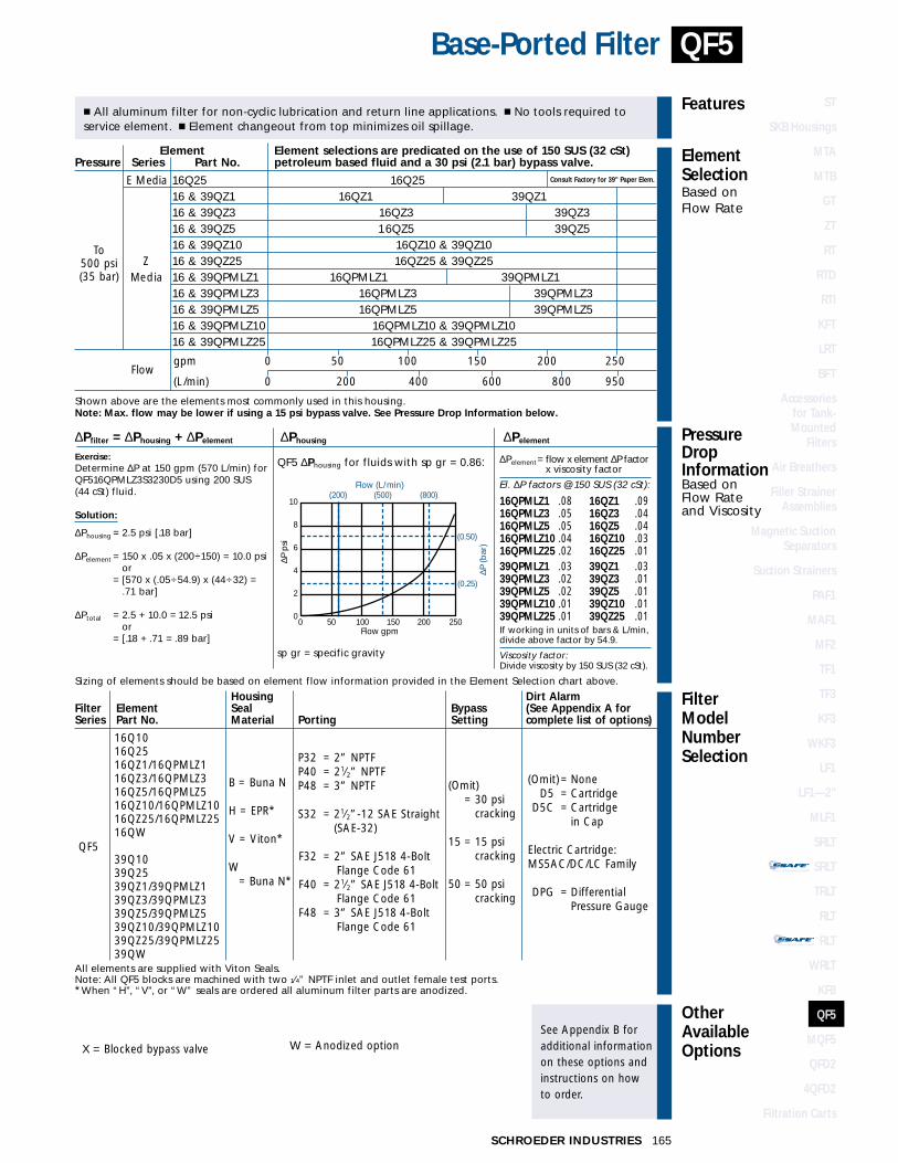
STAND-ALONE DISPOSABLE ELEMENT
™™
STAND-ALONE DISPOSABLE ELEMENT
™™
Element Element selections are predicated on the use of 150 SUS (32 cSt) Pressure Series Part No. petroleum based fluid and a 30 psi (2.1 bar) bypass valve.
E Media 16Q25 16Q25 Consult Factory for 39" Paper Elem.
16 & 39QZ1 16QZ1 39QZ116 & 39QZ3 16QZ3 39QZ316 & 39QZ5 16QZ5 39QZ516 & 39QZ10 16QZ10 & 39QZ10
Z 16 & 39QZ25 16QZ25 & 39QZ25Media 16 & 39QPMLZ1 16QPMLZ1 39QPMLZ1
16 & 39QPMLZ3 16QPMLZ3 39QPMLZ316 & 39QPMLZ5 16QPMLZ5 39QPMLZ516 & 39QPMLZ10 16QPMLZ10 & 39QPMLZ1016 & 39QPMLZ25 16QPMLZ25 & 39QPMLZ25
Flowgpm 0 50 100 150 200 250
(L/min) 0 200 400 600 800 950
Shown above are the elements most commonly used in this housing.Note: Max. flow may be lower if using a 15 psi bypass valve. See Pressure Drop Information below.
FilterModelNumberSelection
OtherAvailableOptions
See Appendix B foradditional informationon these options andinstructions on how to order.
PressureDropInformationBased on Flow Rateand Viscosity
ElementSelectionBased on Flow Rate
Features
Base-Ported Filter
� All aluminum filter for non-cyclic lubrication and return line applications. � No tools required to service element. � Element changeout from top minimizes oil spillage.
QF5 ∆Phousing for fluids with sp gr = 0.86:
∆Pfilter = ∆Phousing + ∆Pelement ∆Phousing ∆Pelement
Exercise:Determine ∆P at 150 gpm (570 L/min) forQF516QPMLZ3S3230D5 using 200 SUS (44 cSt) fluid.
Solution:
∆Phousing = 2.5 psi [.18 bar]
∆Pelement = 150 x .05 x (200÷150) = 10.0 psior
∆Pelement = [570 x (.05÷54.9) x (44÷32) = .71 bar]
∆Ptotal = 2.5 + 10.0 = 12.5 psior
∆Pelement = [.18 + .71 = .89 bar]
Sizing of elements should be based on element flow information provided in the Element Selection chart above.
sp gr = specific gravity
(800)(200) (500)
(0.25)
10
8
6
4
2
0
(0.50)
0 50 100 150 200 250Flow gpm
Flow (L/min)∆P
(bar
)
∆P p
si
∆Pelement= flow x element ∆P factor x viscosity factor
El. ∆P factors @ 150 SUS (32 cSt):
16QPMLZ1 .08 16QZ1 .0916QPMLZ3 .05 16QZ3 .0416QPMLZ5 .05 16QZ5 .0416QPMLZ10 .04 16QZ10 .0316QPMLZ25 .02 16QZ25 .0139QPMLZ1 .03 39QZ1 .0339QPMLZ3 .02 39QZ3 .0139QPMLZ5 .02 39QZ5 .0139QPMLZ10 .01 39QZ10 .0139QPMLZ25 .01 39QZ25 .01If working in units of bars & L/min,divide above factor by 54.9.
Viscosity factor:Divide viscosity by 150 SUS (32 cSt).
X = Blocked bypass valve W = Anodized option
All elements are supplied with Viton Seals.Note: All QF5 blocks are machined with two 1⁄4” NPTF inlet and outlet female test ports. *When “H”, “V”, or “W” seals are ordered all aluminum filter parts are anodized.
QF5
165SCHROEDER INDUSTRIES
P32 = 2” NPTFP40 = 21⁄2” NPTFP48 = 3” NPTF
S32 = 21⁄2”-12 SAE Straight (SAE-32)
F32 = 2” SAE J518 4-BoltFlange Code 61
F40 = 21⁄2” SAE J518 4-BoltFlange Code 61
F48 = 3” SAE J518 4-BoltFlange Code 61
B = Buna N
H = EPR*
V = Viton*
W= Buna N*
Housing Dirt AlarmFilter Element Seal Bypass (See Appendix A forSeries Part No. Material Porting Setting complete list of options)
16Q1016Q2516QZ1/16QPMLZ116QZ3/16QPMLZ316QZ5/16QPMLZ516QZ10/16QPMLZ1016QZ25/16QPMLZ2516QW
39Q1039Q2539QZ1/39QPMLZ139QZ3/39QPMLZ339QZ5/39QPMLZ539QZ10/39QPMLZ1039QZ25/39QPMLZ2539QW
QF5
(Omit) = NoneD5 = Cartridge
D5C = Cartridge in Cap
Electric Cartridge:MS5AC/DC/LC Family
DPG = DifferentialPressure Gauge
To500 psi(35 bar)
(Omit) = 30 psi
cracking
15 = 15 psicracking
50 = 50 psicracking
STAND-ALONE DISPOSABLE ELEMENT
™™
STAND-ALONE DISPOSABLE ELEMENT
™™
ST
SKB Housings
MTA
MTB
GT
ZT
RT
RTD
RTI
KFT
LRT
BFT
Accessories for Tank-Mounted
Filters
Air Breathers
Filler StrainerAssemblies
Magnetic SuctionSeparators
Suction Strainers
PAF1
MAF1
MF2
TF1
TF3
KF3
WKF3
LF1
LF1—2"
MLF1
SRLT
SRLT
TRLT
RLT
RLT
WRLT
KF8
QF5
MQF5
QFD2
4QFD2
Filtration Carts
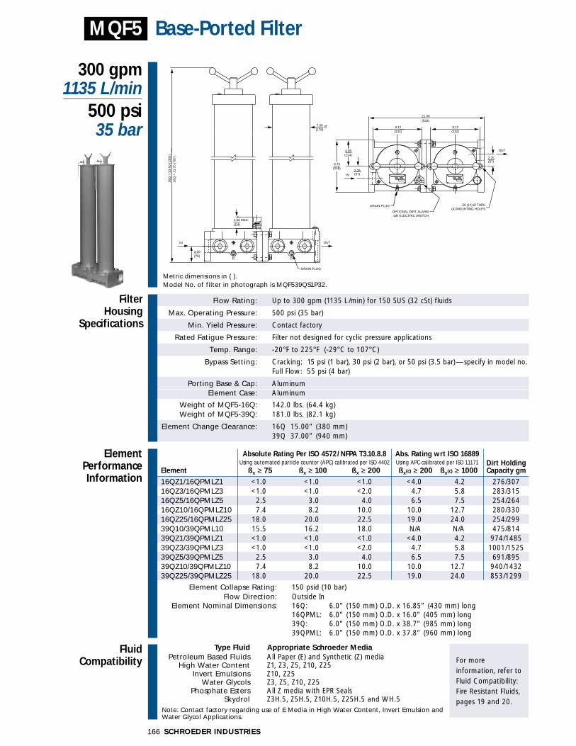
Flow Rating: Up to 300 gpm (1135 L/min) for 150 SUS (32 cSt) fluids
Max. Operating Pressure: 500 psi (35 bar)
Min. Yield Pressure: Contact factory
Rated Fatigue Pressure: Filter not designed for cyclic pressure applications
Temp. Range: -20°F to 225°F (-29°C to 107°C)
Bypass Setting: Cracking: 15 psi (1 bar), 30 psi (2 bar), or 50 psi (3.5 bar)—specify in model no.Full Flow: 55 psi (4 bar)
Porting Base & Cap: AluminumElement Case: Aluminum
Weight of MQF5-16Q: 142.0 lbs. (64.4 kg)Weight of MQF5-39Q: 181.0 lbs. (82.1 kg)
Element Change Clearance: 16Q 15.00” (380 mm)39Q 37.00” (940 mm)
Filter Housing
Specifications
300 gpm1135 L/min
500 psi35 bar
Base-Ported FilterMQF5
Metric dimensions in ( ).Model No. of filter in photograph is MQF539QS1P32.
2.25(57)
DD
4.50 MAX.(114)
3.00(76)
7.00(178)
IN OUT
39Q
= 5
3.50
(13
53)
16Q
= 3
1.75
(79
7)
DRAIN PLUG
2.25(57)
4.88(124)
9.75(248)
9.12(232)
21.00(533)
9.12(232)
DRAIN PLUG
IN
OUT
.56 (14) Ø THRU(4) MOUNTING HOLES
Ø
OPTIONAL DIRT ALARMOR ELECTRIC SWITCH
FluidCompatibility
Type Fluid Appropriate Schroeder MediaPetroleum Based Fluids All Paper (E) and Synthetic (Z) media
High Water Content Z1, Z3, Z5, Z10, Z25Invert Emulsions Z10, Z25
Water Glycols Z3, Z5, Z10, Z25Phosphate Esters All Z media with EPR Seals
Skydrol Z3H.5, Z5H.5, Z10H.5, Z25H.5 and WH.5 Note: Contact factory regarding use of E Media in High Water Content, Invert Emulsion and Water Glycol Applications.
For more information, refer toFluid Compatibility:Fire Resistant Fluids,pages 19 and 20.
SCHROEDER INDUSTRIES166
ElementPerformanceInformation
Absolute Rating Per ISO 4572/NFPA T3.10.8.8 Abs. Rating wrt ISO 16889 Using automated particle counter (APC) calibrated per ISO 4402 Using APC calibrated per ISO 11171 Dirt Holding
Element ßx ≥ 75 ßx ≥ 100 ßx ≥ 200 ßx(c) ≥ 200 ßx(c) ≥ 1000 Capacity gm
16QZ1/16QPMLZ1 <1.0 <1.0 <1.0 <4.0 4.2.2 276/30716QZ3/16QPMLZ3 <1.0 <1.0 <2.0 4.7 5.8.8 283/31516QZ5/16QPMLZ5 2.5 3.0 4.0 6.5 7.5 254/26416QZ10/16QPMLZ10 7.4 8.2 10.0 10.0 12.7 280/33016QZ25/16QPMLZ25 18.0 20.0 22.5 19.0 24.00 254/29939Q10/39QPML10 15.5 16.2 18.0 N/A N/A 475/81439QZ1/39QPMLZ1 <1.0 <1.0 <1.0 <4.0 4.2 974/148539QZ3/39QPMLZ3 <1.0 <1.0 <2.0 4.7 5.8 1001/152539QZ5/39QPMLZ5 2.5 3.0 4.0 6.5 7.5 691/89539QZ10/39QPMLZ10 7.4 8.2 10.0 10.0 12.7 940/143239QZ25/39QPMLZ25 18.0 20.0 22.5 19.0 24.0 853/1299
Element Collapse Rating: 150 psid (10 bar)Flow Direction: Outside In
Element Nominal Dimensions: 16Q: 6.0” (150 mm) O.D. x 16.85” (430 mm) long16QPML: 6.0” (150 mm) O.D. x 16.0” (405 mm) long39Q: 6.0” (150 mm) O.D. x 38.7” (985 mm) long39QPML: 6.0” (150 mm) O.D. x 37.8” (960 mm) long

ST
SKB Housings
MTA
MTB
GT
ZT
RT
RTD
RTI
KFT
LRT
BFT
Accessories for Tank-Mounted
Filters
Air Breathers
Filler StrainerAssemblies
Magnetic SuctionSeparators
Suction Strainers
PAF1
MAF1
MF2
TF1
TF3
KF3
WKF3
LF1
LF1—2"
MLF1
SRLT
SRLT
TRLT
RLT
RLT
WRLT
KF8
QF5
MQF5
QFD2
4QFD2
Filtration Carts
STAND-ALONE DISPOSABLE ELEMENT
™™
STAND-ALONE DISPOSABLE ELEMENT
™™
FilterModelNumberSelection
OtherAvailableOptions
See Appendix B foradditional informationon these options andinstructions on how to order.
PressureDropInformationBased on Flow Rateand Viscosity
ElementSelectionBased on Flow Rate
Features
Base-Ported Filter
� All aluminum dual filter for non-cyclic lubrication and return line applications. � No tools required toservice element. � Element changeout from top minimizes oil spillage.
MQF5 ∆Phousing for fluids with sp gr = 0.86:
∆Pfilter = ∆Phousing + ∆Pelement ∆Phousing ∆Pelement
Exercise:Determine ∆P at 250 gpm (950 L/min) for MQF539QPMLZ3S3230D5 using 200 SUS (44 cSt) fluid.
Solution:
∆Phousing = 4.0 psi [.30 bar]
∆Pelement = 250 x .01 x (200÷150) = 6.7 psi÷2 = 1.7 psior
∆Pelement = [950 x (.01÷54.9) x (44÷32) = .47 bar ÷2 = .12 bar]
∆Ptotal = 4.0 + 1.7 = 5.7 psior
∆Pelement = [.30 + .12 = .42 bar]
Sizing of elements should be based on element flow information provided in the Element Selection chart above.
sp gr = specific gravity
(0.25)
(0.50)
(200) (500) (800) (1000)10
8
6
4
2
0 0 50 100 150 200 250 300
Flow gpm
Flow (L/min)∆P
(bar
)
∆P p
si
∆Pelement= flow x element ∆P factor x viscosity factor
El. ∆P factors @ 150 SUS (32 cSt):
16QPMLZ1 .04 16QZ1 .0516QPMLZ3 .03 16QZ3 .0216QPMLZ5 .03 16QZ5 .0216QPMLZ10 .02 16QZ10 .0216QPMLZ25 .01 16QZ25 .0139QPMLZ1 .02 39QZ1 .0239QPMLZ3 .01 39QZ3 .0139QPMLZ5 .01 39QZ5 .0139QPMLZ10 .01 39QZ10 .0139QPMLZ25 .01 39QZ25 .01If working in units of bars & L/min,divide above factor by 54.9.
Viscosity factor:Divide viscosity by 150 SUS (32 cSt).
MQF5
167SCHROEDER INDUSTRIES
X = Blocked bypass valve W = Anodized option
All elements are supplied with Viton Seals.Note: All MQF5 blocks are machined with two 1⁄4” NPTF inlet and outlet female test ports. *When “H” seals are ordered all aluminum filter parts are anodized.
P32 = 2” NPTFP40 = 21⁄2” NPTFP48 = 3” NPTF
S32 = 21⁄2”-12 SAE Straight (SAE-32)
F32 = 2” SAE J518 4-BoltFlange Code 61
F40 = 21⁄2” SAE J518 4-BoltFlange Code 61
F48 = 3” SAE J518 4-BoltFlange Code 61
B = Buna N
H = EPR*
V = Viton
16Q1016Q2516QZ1/16QPMLZ116QZ3/16QPMLZ316QZ5/16QPMLZ516QZ10/16QPMLZ1016QZ25/16QPMLZ2516QW
39Q1039Q2539QZ1/39QPMLZ139QZ3/39QPMLZ339QZ5/39QPMLZ539QZ10/39QPMLZ1039QZ25/39QPMLZ2539QW
MQF5
(Omit) = NoneD5 = Cartridge
D5C = Cartridge in Cap
Electric Cartridge:MS5AC/DC/LC Family
DPG = DifferentialPressure Gauge
(Omit) = 30 psi
cracking
15 = 15 psicracking
50 = 50 psicracking
Element Element selections are predicated on the use of 150 SUS (32 cSt) Pressure Series Part No. petroleum based fluid and a 30 psi (2.1 bar) bypass valve.
E Media 16 & 39Q25 16Q25 & 39Q2516 & 39QZ1 16QZ1 39QZ116 & 39QZ3 16QZ3 39QZ316 & 39QZ5 16QZ516 & 39QZ10 16QZ10 & 39QZ1016 & 39QZ25 16QZ25 & 39QZ2516 & 39QPMLZ1 16QPMLZ1 39QPMLZ116 & 39QPMLZ3 16QPMLZ3 39QPMLZ316 & 39QPMLZ5 16QPMLZ5 39QPMLZ516 & 39QPMLZ10 16QPMLZ10 & 39QPMLZ1016 & 39QPMLZ25 16QPMLZ25 & 39QPMLZ25
Flowgpm 0 50 100 150 200 250 300
(L/min) 0 200 400 600 800 1000 1135
Shown above are the elements most commonly used in this housing.Note: Max. flow may be lower if using a 15 psi bypass valve. See Pressure Drop Information below.
To500 psi(35 bar)
ZMedia
Housing Dirt AlarmFilter Element Seal Bypass (See Appendix A forSeries Part No. Material Porting Setting complete list of options)
STAND-ALONE DISPOSABLE ELEMENT
™™
STAND-ALONE DISPOSABLE ELEMENT
™™
ST
SKB Housings
MTA
MTB
GT
ZT
RT
RTD
RTI
KFT
LRT
BFT
Accessories for Tank-Mounted
Filters
Air Breathers
Filler StrainerAssemblies
Magnetic SuctionSeparators
Suction Strainers
PAF1
MAF1
MF2
TF1
TF3
KF3
WKF3
LF1
LF1—2"
MLF1
SRLT
SRLT
TRLT
RLT
RLT
WRLT
KF8
QF5
MQF5
QFD2
4QFD2
Filtration Carts

Flow Rating: Up to 250 gpm (950 L/min) for 150 SUS (32 cSt) fluids
Max. Operating Pressure: 200 psi (15 bar)
Min. Yield Pressure: Contact factory
Rated Fatigue Pressure: Filter not designed for cyclic pressure applications
Temp. Range: -20°F to 225°F (-29°C to 107°C)
Bypass Setting: Cracking: 15 psi (1 bar), 30 psi (2 bar), or 50 psi (3.5 bar)—specify in model no.Full Flow: 69 psi (5 bar)
Porting Base & Cap: AluminumElement Case: Aluminum
Weight of QFD2-16Q: 511.0 lbs. (231.8 kg)Weight of QFD2-39Q: 550.0 lbs. (249.5 kg)
Element Change Clearance: 16Q 15.00” (380 mm)39Q 37.00” (940 mm)
Filter Housing
Specifications
250 gpm950 L/min
200 psi15 bar
Duplex Base-Ported FilterQFD2
Metric dimensions in ( ).Model No. of filter in photograph is QFD239QS7F40.
27.1
2 (6
89)
PO
RT
TO
PO
RT
25.4
3 (6
46)
SA
E 4
-BO
LT F
LG. P
OR
T
7.00(178)
Ø
OPTIONAL BASE CHANNEL
39.00(991)
OUT
IN
A
A
19.50(495)
4.50 MAX.(114)
VIEW A-A
OPTIONAL DIRT ALARMOR ELECTRIC SWITCH
39Q
= 5
3.50
(13
53)
16Q
= 3
1.75
(79
7)
39Q
= 5
5.28
(13
98)
16Q
= 3
3.53
(84
2)
FluidCompatibility
Type Fluid Appropriate Schroeder MediaPetroleum Based Fluids All Paper (E) and Synthetic (Z) media
High Water Content Z1, Z3, Z5, Z10, Z25Invert Emulsions Z10, Z25
Water Glycols Z3, Z5, Z10, Z25Phosphate Esters All Z media with EPR Seals
Skydrol Z3H.5, Z5H.5, Z10H.5, Z25H.5 and WH.5 Note: Contact factory regarding use of E Media in High Water Content, Invert Emulsion and Water Glycol Applications.
For more information, refer toFluid Compatibility:Fire Resistant Fluids,pages 19 and 20.
SCHROEDER INDUSTRIES168
ElementPerformanceInformation
Absolute Rating Per ISO 4572/NFPA T3.10.8.8 Abs. Rating wrt ISO 16889 Using automated particle counter (APC) calibrated per ISO 4402 Using APC calibrated per ISO 11171 Dirt Holding
Element ßx ≥ 75 ßx ≥ 100 ßx ≥ 200 ßx(c) ≥ 200 ßx(c) ≥ 1000 Capacity gm
16QZ1/16QPMLZ1 <1.0 <1.0 <1.0 <4.0 4.2.2 276/30716QZ3/16QPMLZ3 <1.0 <1.0 <2.0 4.7 5.8.8 283/31516QZ5/16QPMLZ5 2.5 3.0 4.0 6.5 7.5 254/26416QZ10/16QPMLZ10 7.4 8.2 10.0 10.0 12.7 280/33016QZ25/16QPMLZ25 18.0 20.0 22.5 19.0 24.00 254/29939Q10/39QPML10 15.5 16.2 18.0 N/A N/A 475/81439QZ1/39QPMLZ1 <1.0 <1.0 <1.0 <4.0 4.2 974/148539QZ3/39QPMLZ3 <1.0 <1.0 <2.0 4.7 5.8 1001/152539QZ5/39QPMLZ5 2.5 3.0 4.0 6.5 7.5 691/89539QZ10/39QPMLZ10 7.4 8.2 10.0 10.0 12.7 940/143239QZ25/39QPMLZ25 18.0 20.0 22.5 19.0 24.0 853/1299
Element Collapse Rating: 150 psid (10 bar)Flow Direction: Outside In
Element Nominal Dimensions: 16Q: 6.0” (150 mm) O.D. x 16.85” (430 mm) long16QPML: 6.0” (150 mm) O.D. x 16.0” (405 mm) long39Q: 6.0” (150 mm) O.D. x 38.7” (985 mm) long39QPML: 6.0” (150 mm) O.D. x 37.8” (960 mm) long
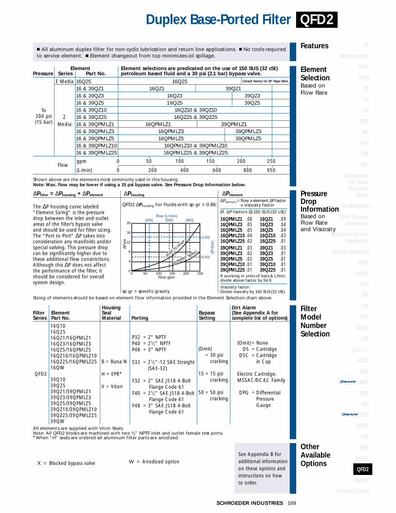
STAND-ALONE DISPOSABLE ELEMENT
™™
STAND-ALONE DISPOSABLE ELEMENT
™™
X = Blocked bypass valve W = Anodized option
All elements are supplied with Viton Seals.Note: All QFD2 blocks are machined with two 1⁄4” NPTF inlet and outlet female test ports. *When “H” seals are ordered all aluminum filter parts are anodized.
P32 = 2” NPTFP40 = 21⁄2” NPTFP48 = 3” NPTF
S32 = 21⁄2”-12 SAE Straight (SAE-32)
F32 = 2” SAE J518 4-BoltFlange Code 61
F40 = 21⁄2” SAE J518 4-BoltFlange Code 61
F48 = 3” SAE J518 4-BoltFlange Code 61
B = Buna N
H = EPR*
V = Viton
16Q1016Q2516QZ1/16QPMLZ116QZ3/16QPMLZ316QZ5/16QPMLZ516QZ10/16QPMLZ1016QZ25/16QPMLZ2516QW
39Q1039Q2539QZ1/39QPMLZ139QZ3/39QPMLZ339QZ5/39QPMLZ539QZ10/39QPMLZ1039QZ25/39QPMLZ2539QW
QFD2
(Omit) = NoneD5 = Cartridge
D5C = Cartridge in Cap
Electric Cartridge:MS5AC/DC/LC Family
DPG = DifferentialPressureGauge
(Omit) = 30 psi
cracking
15 = 15 psicracking
50 = 50 psicracking
FilterModelNumberSelection
OtherAvailableOptions
See Appendix B foradditional informationon these options andinstructions on how to order.
PressureDropInformationBased on Flow Rateand Viscosity
ElementSelectionBased on Flow Rate
Features
Duplex Base-Ported Filter
� All aluminum duplex filter for non-cyclic lubrication and return line applications. � No tools requiredto service element. � Element changeout from top minimizes oil spillage.
QFD2 ∆Phousing for fluids with sp gr = 0.86:
∆Pfilter = ∆Phousing + ∆Pelement ∆Phousing ∆Pelement
Sizing of elements should be based on element flow information provided in the Element Selection chart above.sp gr = specific gravity
0 50 100 150 200 250Flow gpm
∆P (b
ar)
(1.00)
(0.50)
(800)(200) (500)20
16
12
8
4
0
Flow (L/min)
∆P p
si
PORT T
O PORT
ELEMENT SIZING
∆Pelement= flow x element ∆P factor x viscosity factor
El. ∆P factors @ 150 SUS (32 cSt):
16QPMLZ1 .08 16QZ1 .0916QPMLZ3 .05 16QZ3 .0416QPMLZ5 .05 16QZ5 .0416QPMLZ10 .04 16QZ10 .0316QPMLZ25 .02 16QZ25 .0139QPMLZ1 .03 39QZ1 .0339QPMLZ3 .02 39QZ3 .0139QPMLZ5 .02 39QZ5 .0139QPMLZ10 .01 39QZ10 .0139QPMLZ25 .01 39QZ25 .01If working in units of bars & L/min,divide above factor by 54.9.
Viscosity factor:Divide viscosity by 150 SUS (32 cSt).
QFD2
169SCHROEDER INDUSTRIES
Element Element selections are predicated on the use of 150 SUS (32 cSt) Pressure Series Part No. petroleum based fluid and a 30 psi (2.1 bar) bypass valve.
E Media 16Q25 16Q25 Consult Factory for 39" Paper Elem.
16 & 39QZ1 16QZ1 39QZ116 & 39QZ3 16QZ3 39QZ316 & 39QZ5 16QZ5 39QZ516 & 39QZ10 16QZ10 & 39QZ10
Z 16 & 39QZ25 16QZ25 & 39QZ25Media 16 & 39QPMLZ1 16QPMLZ1 39QPMLZ1
16 & 39QPMLZ3 16QPMLZ3 39QPMLZ316 & 39QPMLZ5 16QPMLZ5 39QPMLZ516 & 39QPMLZ10 16QPMLZ10 & 39QPMLZ1016 & 39QPMLZ25 16QPMLZ25 & 39QPMLZ25
Flowgpm 0 50 100 150 200 250
(L/min) 0 200 400 600 800 950
Shown above are the elements most commonly used in this housing.Note: Max. flow may be lower if using a 15 psi bypass valve. See Pressure Drop Information below.
To200 psi(15 bar)
Housing Dirt AlarmFilter Element Seal Bypass (See Appendix A forSeries Part No. Material Porting Setting complete list of options)
STAND-ALONE DISPOSABLE ELEMENT
™™
STAND-ALONE DISPOSABLE ELEMENT
™™
The ∆P housing curve labeled“Element Sizing” is the pressuredrop between the inlet and outlet areas of the filter’s bypass valveand should be used for filter sizing.The “Port to Port” ∆P takes intoconsideration any manifolds and/orspecial valving. This pressure dropcan be significantly higher due tothese additional flow constrictions.Although this ∆P does not affectthe performance of the filter, itshould be considered for overallsystem design.
ST
SKB Housings
MTA
MTB
GT
ZT
RT
RTD
RTI
KFT
LRT
BFT
Accessories for Tank-Mounted
Filters
Air Breathers
Filler StrainerAssemblies
Magnetic SuctionSeparators
Suction Strainers
PAF1
MAF1
MF2
TF1
TF3
KF3
WKF3
LF1
LF1—2"
MLF1
SRLT
SRLT
TRLT
RLT
RLT
WRLT
KF8
QF5
MQF5
QFD2
4QFD2
Filtration Carts
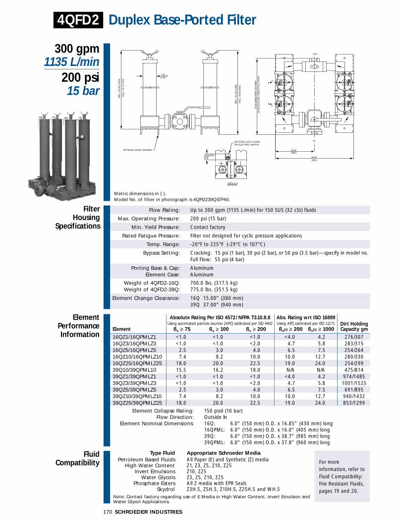
Flow Rating: Up to 300 gpm (1135 L/min) for 150 SUS (32 cSt) fluids
Max. Operating Pressure: 200 psi (15 bar)
Min. Yield Pressure: Contact factory
Rated Fatigue Pressure: Filter not designed for cyclic pressure applications
Temp. Range: -20°F to 225°F (-29°C to 107°C)
Bypass Setting: Cracking: 15 psi (1 bar), 30 psi (2 bar), or 50 psi (3.5 bar)—specify in model no.Full Flow: 55 psi (4 bar)
Porting Base & Cap: AluminumElement Case: Aluminum
Weight of 4QFD2-16Q: 700.0 lbs. (317.5 kg)Weight of 4QFD2-39Q: 775.0 lbs. (351.5 kg)
Element Change Clearance: 16Q 15.00” (380 mm)39Q 37.00” (940 mm)
Filter Housing
Specifications
300 gpm1135 L/min
200 psi15 bar
Duplex Base-Ported Filter4QFD2
Metric dimensions in ( ).Model No. of filter in photograph is 4QFD239QS7F40.
7.00(178)
Ø
OPTIONAL BASE CHANNEL
39.00(991)
OUT
IN
A
A
19.50(495)
37.6
2 (9
56)
PO
RT
TO
PO
RT
35.9
3 (9
13)
SA
E 4
-BO
LT F
LG. P
OR
T
4.50 MAX.(114)
VIEW A-A
OPTIONAL DIRT ALARMOR ELECTRIC SWITCH
39Q
= 5
5.28
(13
98)
16Q
= 3
3.53
(84
2)
39Q
= 5
3.50
(13
53)
16Q
= 3
1.75
(79
7)
FluidCompatibility
Type Fluid Appropriate Schroeder MediaPetroleum Based Fluids All Paper (E) and Synthetic (Z) media
High Water Content Z1, Z3, Z5, Z10, Z25Invert Emulsions Z10, Z25
Water Glycols Z3, Z5, Z10, Z25Phosphate Esters All Z media with EPR Seals
Skydrol Z3H.5, Z5H.5, Z10H.5, Z25H.5 and WH.5 Note: Contact factory regarding use of E Media in High Water Content, Invert Emulsion and Water Glycol Applications.
For more information, refer toFluid Compatibility:Fire Resistant Fluids,pages 19 and 20.
SCHROEDER INDUSTRIES170
ElementPerformanceInformation
Absolute Rating Per ISO 4572/NFPA T3.10.8.8 Abs. Rating wrt ISO 16889 Using automated particle counter (APC) calibrated per ISO 4402 Using APC calibrated per ISO 11171 Dirt Holding
Element ßx ≥ 75 ßx ≥ 100 ßx ≥ 200 ßx(c) ≥ 200 ßx(c) ≥ 1000 Capacity gm
16QZ1/16QPMLZ1 <1.0 <1.0 <1.0 <4.0 4.2.2 276/30716QZ3/16QPMLZ3 <1.0 <1.0 <2.0 4.7 5.8.8 283/31516QZ5/16QPMLZ5 2.5 3.0 4.0 6.5 7.5 254/26416QZ10/16QPMLZ10 7.4 8.2 10.0 10.0 12.7 280/33016QZ25/16QPMLZ25 18.0 20.0 22.5 19.0 24.00 254/29939Q10/39QPML10 15.5 16.2 18.0 N/A N/A 475/81439QZ1/39QPMLZ1 <1.0 <1.0 <1.0 <4.0 4.2 974/148539QZ3/39QPMLZ3 <1.0 <1.0 <2.0 4.7 5.8 1001/152539QZ5/39QPMLZ5 2.5 3.0 4.0 6.5 7.5 691/89539QZ10/39QPMLZ10 7.4 8.2 10.0 10.0 12.7 940/143239QZ25/39QPMLZ25 18.0 20.0 22.5 19.0 24.0 853/1299
Element Collapse Rating: 150 psid (10 bar)Flow Direction: Outside In
Element Nominal Dimensions: 16Q: 6.0” (150 mm) O.D. x 16.85” (430 mm) long16QPML: 6.0” (150 mm) O.D. x 16.0” (405 mm) long39Q: 6.0” (150 mm) O.D. x 38.7” (985 mm) long39QPML: 6.0” (150 mm) O.D. x 37.8” (960 mm) long
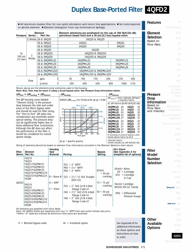
STAND-ALONE DISPOSABLE ELEMENT
™™
STAND-ALONE DISPOSABLE ELEMENT
™™
FilterModelNumberSelection
OtherAvailableOptions
See Appendix B foradditional informationon these options andinstructions on how to order.
PressureDropInformationBased on Flow Rateand Viscosity
ElementSelectionBased on Flow Rate
Features
Duplex Base-Ported Filter
� All aluminum duplex filter for non-cyclic lubrication and return line applications. � No tools requiredto service element. � Element changeout from top minimizes oil spillage.
4QFD2 ∆Phousing for fluids with sp gr =0.86:
∆Pfilter = ∆Phousing + ∆Pelement ∆Phousing ∆Pelement
Sizing of elements should be based on element flow information provided in the Element Selection chart above.
sp gr = specific gravity
(300) (600) (900)
(0.25)
16
14
12
10
8
6
4
2
0
(0.50)
(0.75)
(1.00)
0 50 100 150 200 250 300Flow gpm
Flow (L/min)∆P
(bar
)
∆P p
si
PORT T
O PORT
ELEMENT SIZING
∆Pelement= flow x element ∆P factor x viscosity factor
El. ∆P factors @ 150 SUS (32 cSt):
16QPMLZ1 .04 16QZ1 .0516QPMLZ3 .03 16QZ3 .0216QPMLZ5 .03 16QZ5 .0216QPMLZ10 .02 16QZ10 .0216QPMLZ25 .01 16QZ25 .0139QPMLZ1 .02 39QZ1 .0239QPMLZ3 .01 39QZ3 .0139QPMLZ5 .01 39QZ5 .0139QPMLZ10 .01 39QZ10 .0139QPMLZ25 .01 39QZ25 .01If working in units of bars & L/min,divide above factor by 54.9.
Viscosity factor:Divide viscosity by 150 SUS (32 cSt).
4QFD2
171SCHROEDER INDUSTRIES
X = Blocked bypass valve W = Anodized option
All elements are supplied with Viton Seals.Note: All 4QFD2 blocks are machined with two 1⁄4” NPTF inlet and outlet female test ports. *When “H” seals are ordered all aluminum filter parts are anodized.
P32 = 2” NPTFP40 = 21⁄2” NPTFP48 = 3” NPTF
S32 = 21⁄2”-12 SAE Straight (SAE-32)
F32 = 2” SAE J518 4-BoltFlange Code 61
F40 = 21⁄2” SAE J518 4-BoltFlange Code 61
F48 = 3” SAE J518 4-BoltFlange Code 61
B = Buna N
H = EPR*
V = Viton
16Q1016Q2516QZ1/16QPMLZ116QZ3/16QPMLZ316QZ5/16QPMLZ516QZ10/16QPMLZ1016QZ25/16QPMLZ2516QW
39Q1039Q2539QZ1/39QPMLZ139QZ3/39QPMLZ339QZ5/39QPMLZ539QZ10/39QPMLZ1039QZ25/39QPMLZ2539QW
4QFD2
(Omit) = NoneD5 = Cartridge
D5C = Cartridge in Cap
Electric Cartridge:MS5AC/DC/LC Family
DPG = DifferentialPressure Gauge
(Omit) = 30 psi
cracking
15 = 15 psicracking
50 = 50 psicracking
Element Element selections are predicated on the use of 150 SUS (32 cSt) Pressure Series Part No. petroleum based fluid and a 30 psi (2.1 bar) bypass valve.
E Media 16 & 39Q25 16Q25 & 39Q2516 & 39QZ1 16QZ1 39QZ116 & 39QZ3 16QZ3 39QZ316 & 39QZ5 16QZ516 & 39QZ10 16QZ10 & 39QZ1016 & 39QZ25 16QZ25 & 39QZ2516 & 39QPMLZ1 16QPMLZ1 39QPMLZ116 & 39QPMLZ3 16QPMLZ3 39QPMLZ316 & 39QPMLZ5 16QPMLZ5 39QPMLZ516 & 39QPMLZ10 16QPMLZ10 & 39QPMLZ1016 & 39QPMLZ25 16QPMLZ25 & 39QPMLZ25
Flowgpm 0 50 100 150 200 250 300
(L/min) 0 200 400 600 800 1000 1135
Shown above are the elements most commonly used in this housing.Note: Max. flow may be lower if using a 15 psi bypass valve. See Pressure Drop Information below.
To200 psi(15 bar)
ZMedia
Housing Dirt AlarmFilter Element Seal Bypass (See Appendix A forSeries Part No. Material Porting Setting complete list of options)
STAND-ALONE DISPOSABLE ELEMENT
™™
STAND-ALONE DISPOSABLE ELEMENT
™™
The ∆P housing curve labeled“Element Sizing” is the pressuredrop between the inlet and outlet areas of the filter’s bypass valveand should be used for filter sizing.The “Port to Port” ∆P takes intoconsideration any manifolds and/orspecial valving. This pressure dropcan be significantly higher due tothese additional flow constrictions.Although this ∆P does not affectthe performance of the filter, itshould be considered for overallsystem design.
ST
SKB Housings
MTA
MTB
GT
ZT
RT
RTD
RTI
KFT
LRT
BFT
Accessories for Tank-Mounted
Filters
Air Breathers
Filler StrainerAssemblies
Magnetic SuctionSeparators
Suction Strainers
PAF1
MAF1
MF2
TF1
TF3
KF3
WKF3
LF1
LF1—2"
MLF1
SRLT
SRLT
TRLT
RLT
RLT
WRLT
KF8
QF5
MQF5
QFD2
4QFD2
Filtration Carts

SCHROEDER INDUSTRIES172
Portable Filtration Carts
Custom Engineered “On-the-Spot” Units
Provide PortableVersatility
Save...Costly hydraulic oils and components,downtime, and maintenance.
The Schroeder Portable Filtration Cart is a compact,self contained portable filtration system on wheelsequipped with high efficiency, high capacity elementscapable of removing particulate contaminants and/orwater quickly, conveniently and economically. Typicalapplications include:
� Filtering the fluid in a hydraulic reservoir periodicallyas a supplement to continuous filtration by systemfilters.
� Cleaning up a hydraulic system before restartingthe system following component failure.
� Providing clean fluid when re-filling and addingfluid to the reservoir of the system.
� Reclaiming fluid which is contaminated with dirt.
� Pre-filling and cleaning up hydraulic systems onnew or re-built machinery and equipment.
MFB (Contamination Water/Particle RemovalFilter Cart)
The Model MFB Schroeder Portable Filtration Cartprovides dual filtration with both particulate andwater contaminant removal. Select the Schroeder Kelement desired for particulate contaminant removaldown to one micron and combine with the KWwater removal element. (Example: MFB-2KW-2KS3-1.5designates a Filtration Cart with 16 GPM pumpingcapacity, and two KS3 elements in series with twoKW water removal elements.)
HFBMFB

STAND-ALONE DISPOSABLE ELEMENT
™™
STAND-ALONE DISPOSABLE ELEMENT
™™
173SCHROEDER INDUSTRIES
� Dirt Alarm®—indicates when element needs servicing.
� Heavy duty gear pump with high vacuum capabilities.
� Ability to pump high viscosity fluid to 1000 SUS.
� Quick-disconnects to facilitate hookups at inlet andoutlet ports.
� Extra strength cart with large wheels for maximummobility.
� KZ1, KZ3, KZ5, KZ10, KZ25, K3, K10, K25, KM60micron elements for contamination removal.
� KW elements for water removal.
� 115V AC single phase motor standard. 3 phase version available. Contact factory.
� 60 Hz motor standard. 50 Hz version available.Contact factory.
� Configurations available to handle flows higherthan 16 gpm. Contact factory.
� Stationary filter units also available. Contact factory.
Models shown below are furnished with KZ3 & KW elements. For other elements, change the element number in the model number. Example: HFB-2KZ3-1.
Motor Size Filter ElementsComplete 115V A.C. Pump Total Dirt
Model Single Size Model Area Holding WeightNumber Phase (gpm) Number (sq. in.) Capacity lbs (kg)
HFB-2KZ3-1⁄3 1⁄3 hp 4 2KZ3 2200 230 gm 90 (41)
HFB-2KZ3-1 1 hp 10 2KZ3 2200 230 gm 119 (54)
HFB-2KZ3-1.5* 11⁄2 hp 16 2KZ3 2200 230 gm 130 (59)
MFB- 2KWWater Holding
2KW-2KZ3-11 hp 10
2KZ34000 Cap. 600 ml & 139 (63)
230 gm
MFB- 2KWWater Holding
2KW-2KZ3-1.511⁄2 hp 16
2KZ34000 Cap. 500 ml & 151 (68
230 gm*NSN 4300-01-044-7992
Portable Filtration Carts
SchroederSpecialties
OrderingInformation
ST
SKB Housings
MTA
MTB
GT
ZT
RT
RTD
RTI
KFT
LRT
BFT
Accessories for Tank-Mounted
Filters
Air Breathers
Filler StrainerAssemblies
Magnetic SuctionSeparators
Suction Strainers
PAF1
MAF1
MF2
TF1
TF3
KF3
WKF3
LF1
LF1—2"
MLF1
SRLT
SRLT
TRLT
RLT
RLT
WRLT
KF8
QF5
MQF5
QFD2
4QFD2
Filtration Carts