ssp470-touareg 2011 electronics
DESCRIPTION
vw, touareg, electronicsTRANSCRIPT

Protected by copyright. C
opying
for p
rivat
e or
com
mer
cial
pur
pose
s, in
par
t or i
n w
hole
, is
not p
erm
itted
unles
s authorise
d by Volkswagen AG. Volkswagen AG does not guarantee or accept any liability with respect to the correctness ofinform
ation in this document.Copyright by Volkswagen AG.
Service Training
Self-study Programme 470
The Touareg 2011 Electrics/electronicsDesign and Function

Protected by copyright. C
opying
for p
rivat
e or
com
mer
cial
pur
pose
s, in
par
t or i
n w
hole
, is
not p
erm
itted
unles
s authorise
d by Volkswagen AG. Volkswagen AG does not guarantee or accept any liability with respect to the correctness ofinform
ation in this document.Copyright by Volkswagen AG.
2
S470_001
The self-study programme portrays the design and function of new developments.The contents will not be updated.
For current testing, adjustment and repair instructions, refer to the relevant service literature. Attention
Note
The Touareg 2011 sets new standards in the area of electrics/electronics. Of all the latest Volkswagen vehicles, it features the most modern and innovative network that enables communication among all electronic control units.
For the first time at Volkswagen, two new data transfer systems have been introduced with the new Touareg in addition to the familiar CAN data bus and LIN data bus. The new FlexRay data bus joins the control units of the improved driver assist system for adaptive cruise control ACC. With the MOST bus, the infotainment system uses the most modern fibre-optic technology and thereby boasts new highlights in terms of function, display and controls.
As a luxury class vehicle, the Touareg 2011 not only has a modern infotainment system and improved driver assist systems but also completely newly developed functions, such as Area View and dynamic light assist.
This self-study programme is intended to help you become familiar with the electrics/electronics and also the driver assist systems employed in the Touareg 2011 and to understand how they interact.

Protected by copyright. C
opying
for p
rivat
e or
com
mer
cial
pur
pose
s, in
par
t or i
n w
hole
, is
not p
erm
itted
unles
s authorise
d by Volkswagen AG. Volkswagen AG does not guarantee or accept any liability with respect to the correctness ofinform
ation in this document.Copyright by Volkswagen AG.
3
Introduction . . . . . . . . . . . . . . . . . . . . . . . . . . . . . . . . . . . . . . . . . . . . . . . . . . . . . 4
Electrical system . . . . . . . . . . . . . . . . . . . . . . . . . . . . . . . . . . . . . . . . . . . . . . . . . .6
Convenience electronics . . . . . . . . . . . . . . . . . . . . . . . . . . . . . . . . . . . . . . . . . . . 19
Driver assist systems . . . . . . . . . . . . . . . . . . . . . . . . . . . . . . . . . . . . . . . . . . . . . 25
Infotainment. . . . . . . . . . . . . . . . . . . . . . . . . . . . . . . . . . . . . . . . . . . . . . . . . . . . 48
Glossary . . . . . . . . . . . . . . . . . . . . . . . . . . . . . . . . . . . . . . . . . . . . . . . . . . . . . . 50
Test yourself . . . . . . . . . . . . . . . . . . . . . . . . . . . . . . . . . . . . . . . . . . . . . . . . . . . 53
Contents
Protected by copyright. C
opying
for p
rivat
e or
com
mer
cial
pur
pose
s, in
par
t or i
n w
hole
, is
not p
erm
itted
unles
s authorise
d by Volkswagen AG. Volkswagen AG does not guarantee or accept any liability with respect to the correctness ofinform
ation in this document.Copyright by Volkswagen AG.
4
Introduction
OverviewTo start with, the diverse new features of the electrics and electronics of the Touareg 2011 are given some clarity. Listed as follows, therefore, are the main participating new components and functions, which are allocated to the two large main groups infotainment and driver assist systems.However, note that as networking of the most diverse vehicle systems intensifies because components are being combined to realise several vehicle functions, so clear assignment to one system constitutes a simplification, this in reality may not be a representation of the actual conditions in certain circumstances.
Infotainment
The following components and component groups have either been further developed or added as new items:
● MOST data bus● Dash panel insert with 7" TFT colour display (premium)● Control unit for information electronics 1 with
- internal hard-drive- Telephone module with Bluetooth, GSM part (optional)- Navigation module- Media player
● DYNAUDIO sound system● Decentralised radio tuner● TV tuner (optional) ● Additional DVD changer (optional)
The following infotainment systems and functions are available, for example, as further developments in the Touareg 2011 or are new additions:
- Animated 3D navigation guidance in dash panel insert (premium)- Display and operation of the surrounding area features using the Rear View and Area View (optional) functions
on the touch screen of the infotainment in the centre console- Premium telephone connection (equates to permanently installed telephone with dedicated SIM card slot)- Standard Bluetooth module (integrated) has to be enabled via PR number- Radio/navigation system RNS 850
Further information on the subject of infotainment can be found in self-study programme 473 "Infotainment in the Touareg 2011".
Protected by copyright. C
opying
for p
rivat
e or
com
mer
cial
pur
pose
s, in
par
t or i
n w
hole
, is
not p
erm
itted
unles
s authorise
d by Volkswagen AG. Volkswagen AG does not guarantee or accept any liability with respect to the correctness ofinform
ation in this document.Copyright by Volkswagen AG.
5
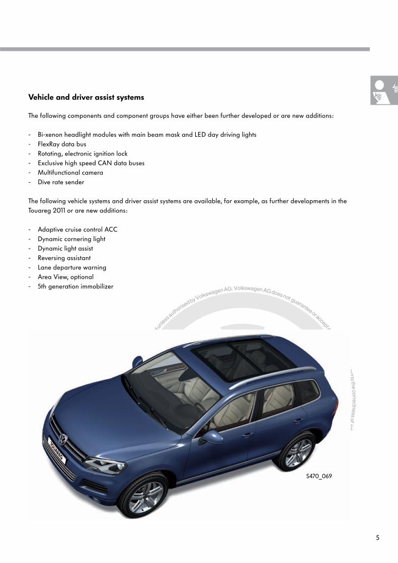
Vehicle and driver assist systems
The following components and component groups have either been further developed or are new additions:
- Bi-xenon headlight modules with main beam mask and LED day driving lights- FlexRay data bus- Rotating, electronic ignition lock- Exclusive high speed CAN data buses- Multifunctional camera- Dive rate sender
The following vehicle systems and driver assist systems are available, for example, as further developments in the Touareg 2011 or are new additions:
- Adaptive cruise control ACC- Dynamic cornering light- Dynamic light assist- Reversing assistant- Lane departure warning- Area View, optional- 5th generation immobilizer
S470_069

Protected by copyright. C
opying
for p
rivat
e or
com
mer
cial
pur
pose
s, in
par
t or i
n w
hole
, is
not p
erm
itted
unles
s authorise
d by Volkswagen AG. Volkswagen AG does not guarantee or accept any liability with respect to the correctness ofinform
ation in this document.Copyright by Volkswagen AG.
6
Electrical system
The networking conceptFor the launch of the Touareg, the highest level of infotainment equipment is installed. This means that in all instances RNS 850 and MOST fibre-optics are used. The data bus diagnostic interface J533 forms the interface for communication for the following data bus systems:
- Powertrain CAN data bus - Chassis CAN data bus - Display and operation CAN data bus - Convenience CAN data bus- Extended CAN data bus
All of the CAN data buses are high speed buses with a data transfer rate of 500kBit/s.
The FlexRay data bus, installed depending on the optional ACC, meets the higher demands of future networks, particularly with regards to a higher data transfer rate compared with the familiar CAN data bus. This is a standard that all manufacturers apply in which the data transfer rate is 10MBit/s.
J623 J624
J492 J197
n
o
J519J446J791
J136J502
J364
J885* J412*J255
E265 R*
J533
J285
T16
Key
Powertrain CAN data bus
Chassis CAN data bus
Convenience CAN data bus
Display and operation CAN data bus
Infotainment CAN data bus
Extended CAN data bus
LIN data bus
FlexRay data bus
MOST data bus
m
f
h

Protected by copyright. C
opying
for p
rivat
e or
com
mer
cial
pur
pose
s, in
par
t or i
n w
hole
, is
not p
erm
itted
unles
s authorise
d by Volkswagen AG. Volkswagen AG does not guarantee or accept any liability with respect to the correctness ofinform
ation in this document.Copyright by Volkswagen AG.
7
KeyE221 Operating unit in steering wheelE265 Operating and display unit for Climatronic in rearG85 Steering angle senderG397 Rain and light sensorG419 ESP sensor unitJ104 ABS control unitJ136 Control unit for seat and steering column adjustment
with memory functionJ197 Adaptive suspension control unitJ217 Automatic gearbox control unitJ234 Airbag control unitJ255 Climatronic control unitJ285 Control unit in dash panel insertJ345 Trailer detector control unitJ364 Auxiliary heater control unitJ386 Driver door control unitJ387 Front passenger door control unitJ388 Rear left door control unitJ389 Rear right door control unitJ393 Convenience system central control unitJ412 Mobile telephone operating electronics control unitJ446 Parking aid control unit J492 Four-wheel drive control unitJ501 Multifunction unit control unitJ502 Tyre pressure monitor control unitJ519 Onboard supply control unitJ521 Front passenger seat adjustment with memory control unitJ525 Digital sound package control unitJ527 Steering column electronics control unitJ533 Data bus diagnostic interfaceJ540 Control unit for electromechanical parking brakeJ605 Rear lid control unit J623 Engine control unitJ624 Engine control unit 2J647 Lateral locks control unitJ706 Seat occupied recognition control unitJ772 Reversing camera system control unitJ791 Control unit for parallel parking assistJ885 Interface for infotainment CAN busJ928 Area view camera control unitR Radio RCD 550 (introduced later)R215 Interface for external multimedia devicesT16 16-pin connector
f FlexRay data bush Extended CAN data busm MOST data busn LIN data bus on J533o LIN data bus on J519p LIN data bus on J393
* Only on vehicles without MOST (introduced later)** Depending on equipment
CAN data bus line
LIN data bus line
Private bus
FlexRay data bus line
MOST fibre-optic cable
J389 J387
J388 J386
J525*J772**/J928**R215*
J605 J501
J521 J345
J393 J527
p E221
J217 J234 J706
J647 J540 J104 G85
G419
CVBS
S470_026

Protected by copyright. C
opying
for p
rivat
e or
com
mer
cial
pur
pose
s, in
par
t or i
n w
hole
, is
not p
erm
itted
unles
s authorise
d by Volkswagen AG. Volkswagen AG does not guarantee or accept any liability with respect to the correctness ofinform
ation in this document.Copyright by Volkswagen AG.
8
Electrical system
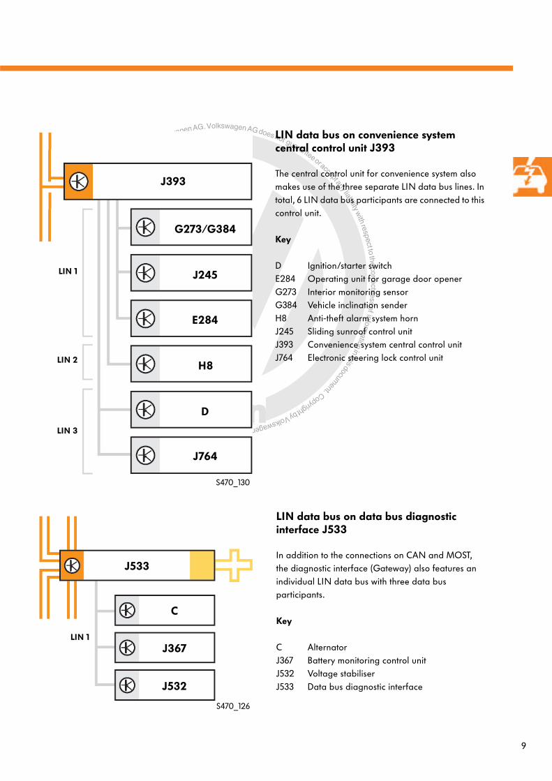
LIN data bus ranges
Shown as an example here are the LIN data bus network ranges from three control units:
- LIN data bus on data bus diagnostic interface J533- LIN data bus on onboard supply control unit 1 J519- LIN data bus on convenience system central control unit J393
In this way, the overview diagram for the overall network on the previous double page spread is given slightly more clarity and shows you how complicated and multi-layered the network architecture has become even beyond the large CAN data bus network ranges.
LIN data bus on Onboard supply control unit 1 J519
Onboard supply control unit 1 has three LIN data bus lines that are separate from each other. In total 9 LIN data bus participants are connected to this control unit.
Key
E1 Light switchG238 Air quality sensorG397 Rain and light sensorG65 High pressure senderJ400 Wiper motor control unitJ519 Onboard supply control unitJ530 Garage door opener control unitJ799 Front right seat ventilation control unitJ800 Front left seat ventilation control unitJ866 Control unit for electrically adjustable
steering column
LIN 1
LIN 2
LIN 3
G65
G238
J866
J519
J800
J400
E1
G397
J530
J799
S470_128
Protected by copyright. C
opying
for p
rivat
e or
com
mer
cial
pur
pose
s, in
par
t or i
n w
hole
, is
not p
erm
itted
unles
s authorise
d by Volkswagen AG. Volkswagen AG does not guarantee or accept any liability with respect to the correctness ofinform
ation in this document.Copyright by Volkswagen AG.
9
LIN data bus on convenience system central control unit J393
The central control unit for convenience system also makes use of the three separate LIN data bus lines. In total, 6 LIN data bus participants are connected to this control unit.
Key
D Ignition/starter switchE284 Operating unit for garage door openerG273 Interior monitoring sensorG384 Vehicle inclination senderH8 Anti-theft alarm system hornJ245 Sliding sunroof control unitJ393 Convenience system central control unitJ764 Electronic steering lock control unit
LIN data bus on data bus diagnostic interface J533
In addition to the connections on CAN and MOST, the diagnostic interface (Gateway) also features an individual LIN data bus with three data bus participants.
Key
C AlternatorJ367 Battery monitoring control unitJ532 Voltage stabiliserJ533 Data bus diagnostic interface
LIN 1
LIN 1
LIN 2
LIN 3
J393
G273/G384
J764
J245
J533
J367
J532
C
H8
D
E284
S470_126
S470_130

Protected by copyright. C
opying
for p
rivat
e or
com
mer
cial
pur
pose
s, in
par
t or i
n w
hole
, is
not p
erm
itted
unles
s authorise
d by Volkswagen AG. Volkswagen AG does not guarantee or accept any liability with respect to the correctness ofinform
ation in this document.Copyright by Volkswagen AG.
10
Electrical system
Key
G752 Dive rate senderJ285 Control unit in dash panel insert
(* Premium dash panel insert)J428 Control unit for adaptive cruise controlJ525 Digital sound package control unitJ533 Data bus diagnostic interfaceJ667 Power output module for left headlightJ668 Power output module for right headlightJ745 Cornering light and headlight range control unitJ769 Lane change assist control unitJ770 Lane change assist control unit 2J794 Control unit 1 for information electronicsJ844 Main beam assist control unit (introduced later)J850 Control unit 2 for adaptive cruise controlJ851 Image processing control unitJ852 Camera control unitJ854 Front left belt tensioner control unitJ855 Front right belt tensioner control unitR RadioR78 TV tunerR161 DVD changer
a Powertrain CAN data busb Display and operation CAN data busd Diagnostic CANfw Chassis CAN data busk Convenience CAN data busL LIN data bus
CAN-Extended, FlexRay, MOST
LVDS
R78
R161
R
J525J285*
J769
J844
J855
J854
G752J851
J850
J428
k
J533
J745
J852
J668
J667
J770
LVDSCVBS
J794L
b
d
fw
a
CAN data bus line
LIN data bus line
FlexRay data bus line
MOST fibre-optic cable
Key
Powertrain CAN data bus
Chassis CAN data bus
Convenience CAN data bus
Display and operation CAN data bus
Extended CAN data bus
LIN data bus
FlexRay data bus
MOST data bus
S470_042
b
Protected by copyright. C
opying
for p
rivat
e or
com
mer
cial
pur
pose
s, in
par
t or i
n w
hole
, is
not p
erm
itted
unles
s authorise
d by Volkswagen AG. Volkswagen AG does not guarantee or accept any liability with respect to the correctness ofinform
ation in this document.Copyright by Volkswagen AG.
11
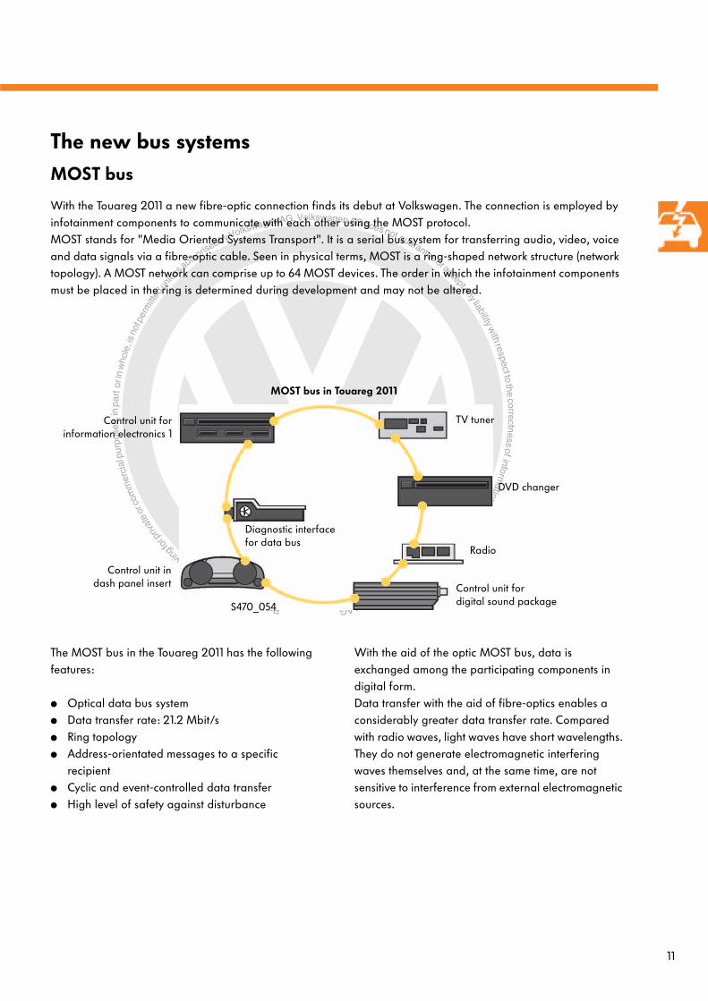
With the Touareg 2011 a new fibre-optic connection finds its debut at Volkswagen. The connection is employed by infotainment components to communicate with each other using the MOST protocol. MOST stands for "Media Oriented Systems Transport". It is a serial bus system for transferring audio, video, voice and data signals via a fibre-optic cable. Seen in physical terms, MOST is a ring-shaped network structure (network topology). A MOST network can comprise up to 64 MOST devices. The order in which the infotainment components must be placed in the ring is determined during development and may not be altered.
The new bus systemsMOST bus
The MOST bus in the Touareg 2011 has the following features:
● Optical data bus system● Data transfer rate: 21.2 Mbit/s● Ring topology● Address-orientated messages to a specific
recipient● Cyclic and event-controlled data transfer● High level of safety against disturbance
Diagnostic interface for data bus
Control unit indash panel insert
DVD changer
Control unit for digital sound package
TV tuner
Radio
Control unit forinformation electronics 1
With the aid of the optic MOST bus, data is exchanged among the participating components in digital form.Data transfer with the aid of fibre-optics enables a considerably greater data transfer rate. Compared with radio waves, light waves have short wavelengths. They do not generate electromagnetic interfering waves themselves and, at the same time, are not sensitive to interference from external electromagnetic sources.
MOST bus in Touareg 2011
S470_054

Protected by copyright. C
opying
for p
rivat
e or
com
mer
cial
pur
pose
s, in
par
t or i
n w
hole
, is
not p
erm
itted
unles
s authorise
d by Volkswagen AG. Volkswagen AG does not guarantee or accept any liability with respect to the correctness ofinform
ation in this document.Copyright by Volkswagen AG.
12
Data protocol
The data to be transferred are sub-divided into frames. Each frame comprises 512bits (64bytes) of digital information. The overall length of a frame is made up of one start and one boundary field, two data fields, one controlling data field, one status and one parity field. The maximum amount of data that can be stored in both data fields is limited to 480bits (60bytes) due to this fixed division.
The data is transferred via 3 channels:- Control channel for controlling data- Synchronous channel for audio and video data transfer (synchronous realtime transfer without
intermediate storage)- Asynchronous channel for large quantities of data, e.g. map data to dashboard insert (asynchronous, event-
controlled data transfer, intermediate storage possible)
On the new Toureg 2011, the size of the synchronous data field is fixed at 40 bytes and the asynchronous data field is fixed at 20 bytes.
Electrical system
Start field = 4bit(preamble)
Boundary field = 4bit(boundary description)
Data field for synchronous data
(synchronous channel)
480bit (60bytes)
Data field for asynchronous data
(asynchronous channel)
Status field = 7bit
Control channel = 16bit
Parity field = 1bit(parity)
S470_096
1 frame = 512bit (64bytes)

Protected by copyright. C
opying
for p
rivat
e or
com
mer
cial
pur
pose
s, in
par
t or i
n w
hole
, is
not p
erm
itted
unles
s authorise
d by Volkswagen AG. Volkswagen AG does not guarantee or accept any liability with respect to the correctness ofinform
ation in this document.Copyright by Volkswagen AG. 13
Outer sheathe.g. orange
Inner sheathalways black
Front surface
Cladding
Core
Structure of fibre-optic cable
The fibre-optic cable comprises several layers:
● the outer coloured coat serves as a means of identification, as protection against mechanical damage and against temperature extremes.
● The black inner coat protects the core against light irradiation.● The cladding (polymer fluoride) is a layer around the core with lower refractive index. Its thickness is several
microns and it ensures that the light fed through the core nearer to the edges is reflected back to the centre of the core, thus preventing "lateral" loss of light from the core.
● The core is the central area of the fibre-optic cable. It is made from specially conditioned plexiglass. It channels the light with practically no loss.
To prevent any loss in the transfer of data, the front surface of the fibre-optic cable has to be smooth, vertical and clean. Dirt and scratches on the front surface could lead to interference and data transfer losses and it could also impair the performance of the fibre-optic cable.
Outer sheathe.g. orange
Inner sheathalways black
Front surface
Cladding
Core
S470_098

Protected by copyright. C
opying
for p
rivat
e or
com
mer
cial
pur
pose
s, in
par
t or i
n w
hole
, is
not p
erm
itted
unles
s authorise
d by Volkswagen AG. Volkswagen AG does not guarantee or accept any liability with respect to the correctness ofinform
ation in this document.Copyright by Volkswagen AG.
14
Electrical system
The higher demands on data rates and also data security necessitate the introduction of time-controlled bus systems with high band width (as a comparison: the CAN data bus is an event-controlled bus system).
FlexRay is a new data bus system, which is debuted in the Touareg 2011. FlexRay is a serial, deterministic and fault-tolerant field bus system for use in automobiles. At 10Mbit/s, FlexRay is twenty times faster than a high speed CAN (which has 500kbit/s).
A further important feature is the guaranteed reaction and latent period. A latent period here describes the time a message needs to travel from the sender to receiver. In this context, deterministic transfer (predetermined, restricted) is another way of describing it. This means that the information reaches the recipient or recipients at a fixed or predetermined point in time (realtime capability).
Unlike the CAN data bus, at least two control units are needed on the FlexRay data bus in order to start the FlexRay. These control units are called cold start control units (KS). Their number is restricted to max. three per FlexRay network.For time-controlled communication within this set network, the shared time basis is formed by the common mode of several control units. Synchronising the clocks within the control units in the FlexRay network means that failure of one individual control unit will not influence the communication behaviour of the other control units. Typically, four control units contribute towards synchronisation of the FlexRay. These control units are designated synchronous control units.If more than four control units are included in a FlexRay network, the remaining control units simply synchronise themselves to the time-basis, which is defined by the synchronous control units. Since these additional control units are integrated in a running, synchronous network, they are designated integration control units.
FlexRay
The FlexRay in the Touareg 2011 has the following features:
● Electric two-wire bus system● Data transfer rate: maximum 10Mbit/s● Mixed topology● Realtime capability● Enables allotted regulations and employment in safety-relevant systems● Synchronous transfer

Protected by copyright. C
opying
for p
rivat
e or
com
mer
cial
pur
pose
s, in
par
t or i
n w
hole
, is
not p
erm
itted
unles
s authorise
d by Volkswagen AG. Volkswagen AG does not guarantee or accept any liability with respect to the correctness ofinform
ation in this document.Copyright by Volkswagen AG.
15
Network structure of FlexRay
FlexRay topology in the Touareg 2011
Star topology Mixed topologyBus topology
Properties for configuring FlexRay topology
- Control units have 2, 4 or more FlexRay connection pins (daisy chain)
- Maximum 4 control units on one branch (inc. star)- Maximum 12 metre line length per branch - Low ohm terminal connection of star and end
control unit - High ohm terminal connection of intermediate
control units
A FlexRay network could take the form of different network structures (topologies):
Key
GW GatewayCU Control unit
High ohm terminal connection (2400 ohms)
Low ohm terminal connection (94 ohms)
GW
GW
GWCUCU
CU
CU
CUCU
CU
CU
CU
CUCU
CU
CU
CUCU
CUCU
CU
J850
J428
J533
J851
Features:
- 2 branches- Active star in Gateway- Max. two control units per branch- Daisy chain wiring- FlexRay communication only with terminal 15
"ON"
Key
J428 Control unit for adaptive cruise controlJ533 Data bus diagnostic interface (Gateway)J850 Control unit 2 for adaptive cruise controlJ851 Image processing control unit
Term. 30, low ohm terminal connection (94 ohms)
Term. 15, high ohm terminal connection (2400 ohms)
Term. 15, low ohm terminal connection (94 ohms)
S470_100S470_102
S470_104
S470_108

Protected by copyright. C
opying
for p
rivat
e or
com
mer
cial
pur
pose
s, in
par
t or i
n w
hole
, is
not p
erm
itted
unles
s authorise
d by Volkswagen AG. Volkswagen AG does not guarantee or accept any liability with respect to the correctness ofinform
ation in this document.Copyright by Volkswagen AG.
16
Data protocol
Communication on the bus works with packages of cycles. One package of cycles comprises 64 cycles (320ms). Each cycle from the cycle package is sub-divided into one large static and one small dynamic segment and lasts 5ms.
Static segment
In the static segment, each control unit has one or more slots (time windows) permanently assigned to it, during which time it can send messages. The quantity and the type of data in this instance is specified for each control unit.This is the deterministic part of the FlexRay, with which assurance can be given that important messages (in the Touareg 2011, those from adaptive cruise control) have been transferred within the prescribed time.
Dynamic segment
The dynamic segment can be used by a control unit to send additional messages. The communication behaviour in the dynamic segment is not deterministic.If a control unit does not issue a message, the next control unit can send their message straight after the mini slot has elapsed. Currently, the dynamic segment is only used in the FlexRay network of the Touareg 2011 for special developer messages. This segment behaves like an event-controlled data transfer system.
Electrical system
Cycle 1 Cycle 2 Cycle 64
....
Slot
1
Slot
2
Slot
3
Slot
4
Slot
n....
Start field (header segment)
Control field (trailer segment)
Effective data field
Min
i 1
Min
i 2
Min
i 3
Min
i 4
Min
i n....
Start field (header segment)
Control field (trailer segment)
Effective data field
S470_112
Static segment
Dynamicsegment

Protected by copyright. C
opying
for p
rivat
e or
com
mer
cial
pur
pose
s, in
par
t or i
n w
hole
, is
not p
erm
itted
unles
s authorise
d by Volkswagen AG. Volkswagen AG does not guarantee or accept any liability with respect to the correctness ofinform
ation in this document.Copyright by Volkswagen AG.
17
Bus physics
The two lines of the FlexRay are designated bus positive (BP, red) and bus negative (BM, blue). The voltage level of both wires change in this example to minimum 2.2V and maximum 2.8V. The voltage difference is at least 600mV.
The FlexRay works with three signal conditions:● "Idle" – the levels of both bus lines are recessive at
2.5V (idling status). Recessive means that the levels can be overwritten by any other control unit.
● "Data 0" – the BP wire has a low voltage level and the BM wire has a high dominant voltage level. Dominant means that this level cannot be overwritten by other control units.
● "Data 1" – the BP wire has a high voltage level and the BM wire has a low dominant voltage level.
With this voltage level configuration, the transfer time for one bit is 100 nanoseconds (ns). If there is no activity (>2660ms) on the bus, synchronisation of the control units will be lost and the FlexRay has to resynchronise itself.
The two lines of the high speed CAN can bus are designated CAN high (CAN_H) and CAN low (CAN_L) The voltage levels of the two lines alternate between minimum 1.5V and maximum 3.5V. The voltage level difference is 2V.
The high speed CAN data bus works with two signal statuses:● "Recessive bit" – the level of the two bus lines is
2.5V;● "Dominant bit" – CAN_L has a low voltage level
and CAN_H has a high voltage level.
With this voltage level configuration, the transfer time for one bit is 2000 nanoseconds (ns).
Changing from high speed CAN data bus to FlexRay has brought about an increased data transfer rate from 500kBit/s to 10MBit/s. This change also has knock-on effects on the bit time and the bus voltage level.
[V][V]
FlexRay High speed CAN data
[ns]2000ns 2000ns[ns]100ns 100ns
1,5
2,5
3,5
2,22,52,8
S470_116 S470_114
Data 1 Data 0
Idle Dominant RecessiveRec. Bus restBus restDominant Dominant

Protected by copyright. C
opying
for p
rivat
e or
com
mer
cial
pur
pose
s, in
par
t or i
n w
hole
, is
not p
erm
itted
unles
s authorise
d by Volkswagen AG. Volkswagen AG does not guarantee or accept any liability with respect to the correctness ofinform
ation in this document.Copyright by Volkswagen AG.
18
Comparison between CAN and FlexRay
FlexRay CAN
Time-controlled
● The point of time at which the medium can be used is fixed.
● The period of use of the medium is fixed.● Time at which recipient receives message is known.
Event-controlled
● The medium is only used when required. ● The point of time at which the medium can be used
depends on the equipment.● Time received is known.● Medium may be overloaded.
Electrical system
Summary of bus systems
CAN low High speed CAN LIN MOST FlexRay
Data rate 100kBit/s 500kBit/s 19,2kBit/s 21MBit/s 10MBit/s
Topology Bus Bus Bus Ring Bus, stern, mixed
Medium Two wire Two wire Single wire Fibre-optic cable Two wire
Fail-safe feature Single wirefunction
Not capableof single wire
- - Not capableof single wire
Repairs to FlexRay wires can be performed in the same way as CAN bus lines using the VAS wiring repair set.
Protected by copyright. C
opying
for p
rivat
e or
com
mer
cial
pur
pose
s, in
par
t or i
n w
hole
, is
not p
erm
itted
unles
s authorise
d by Volkswagen AG. Volkswagen AG does not guarantee or accept any liability with respect to the correctness ofinform
ation in this document.Copyright by Volkswagen AG.
19
Component protection listing for individual components:90 - Component protection for reversible belt tensioner on front right13 - Component protection for cruise control05 - Component protection for access and start authorisation15 - Component protection for airbag control unit06 - Component protection for front passenger seat adjustment36 - Component protection for driver seat adjustment56 - Component protection for radio17 - Component protection for dash panel insert47 - Component protection for sound system08 - Component protection for Climatronic control unit09 - Component protection for onboard supply control unit19 - Component protection for data bus diagnostic interface88 - Component protection for cruise control 20E - Component protection for media player 15F - Component protection for information electronics8F - Component protection for reversible belt tensioner on front left
The 5th generation immobilizerThe new features of the 5th generation immobilizer are purely in relation to the data processes between vehicle and tester via the FAZIT database. The internal process in the vehicle have not been changed. On the 5th generation unit, the FAZIT database makes all decisions online regarding the necessary work measures (one button automatic).
The following tester functions are available:
- Adapting immobilizer- Component protection of master (Gateway) combined system- Component protection of individual components
With the component protection master function, the Gateway is programmed and authorised as a component protection master by FAZIT. This is a key control unit for the following component protection activities among individual components.
The above named control units must be authorised online by FAZIT as otherwise the control unit will be impaired in its functionality to some degree.
To quickly check whether a component protection control unit works, it can also be swapped over providing it works with terminal 30. However, the ignition should not be switched on as otherwise interrogation by the Gateway will ensue in terms of component protection.
Convenience electronics

Protected by copyright. C
opying
for p
rivat
e or
com
mer
cial
pur
pose
s, in
par
t or i
n w
hole
, is
not p
erm
itted
unles
s authorise
d by Volkswagen AG. Volkswagen AG does not guarantee or accept any liability with respect to the correctness ofinform
ation in this document.Copyright by Volkswagen AG.
20
The onboard supply control unitsOn the Touareg 2011, management of the onboard supply and convenience functions are shared by onboard supply control unit J519 and convenience system central control unit J393.
Onboard supply control unit 1 J519
Function
Light functions
● Exterior light master, actuation of lights ● Turn signal slave, actuation of front turn signals● Interior light master ● Leaving home and manual coming home● Interior and control lighting
Driver information
● Exterior temperature, unfiltered● Brake pad/lining wear warning● Brake fluid warning● Coolant warning● Washer water warning● Light warning
Wash/wipe
● Actuation of wiper via LIN● Rain sensor via LIN ● Actuation of washer/dual washer pump ● Actuation of HWS pump
Air conditioner functions
● Front seat heating (not with climate seats)● LIN Gateway for seat heater/seat ventilation
control ● LIN Gateway for pressure sensor and AQS● Actuation of air conditioner compressor
(not hybrid)● Humidity sensor via LIN
Other functions
● Actuation of horn relay● Servotronic with actuation of valve● Read-in reversing light switch ● Read-in bonnet contact● Read-in bonnet contact for ESI● LIN Gateway for UGDO sender● Eco start/stop button, actuation of LED● E-mode button, actuation of LED
Interfaces to J393
● Authorisation for electric steering column lock (discrete and CAN)
● Hardware feedback terminal 15 (CAN signal)
Convenience electronics
S470_040

Protected by copyright. C
opying
for p
rivat
e or
com
mer
cial
pur
pose
s, in
par
t or i
n w
hole
, is
not p
erm
itted
unles
s authorise
d by Volkswagen AG. Volkswagen AG does not guarantee or accept any liability with respect to the correctness ofinform
ation in this document.Copyright by Volkswagen AG.
21
Convenience system central control unit J393
Function
Light functions
● Exterior light slave, actuation of rear lights ● Brake light actuation● Turn signal master● Luggage compartment light actuation
Central locking and ATA
● Central locking master● Radio remote control (315MHz, 434MHz,
868MHz)● Tank flap engage and release● Luggage compartment release● Power latch actuation● Convenience opening/closing● Window regulator and sliding roof authorisation● ATA, actuation of sounder and IRM/TS
Kessy
● Keyless Entry and Keyless Go● Read-in ignition/starter button● Actuation of Kessy aerials
Immobilizer
● Immobilizer master● Read-in transponder of EIL via LIN● Actuation of ESL via LIN
Other functions
● External socket relay● External rear window heater relay● PSR via LIN● Convenience opening, convenience turn signalling● Exterior mirror actuation● Crash signal evaluation● LIN Gateway for UGDO operating unit● Self-diagnosis
Terminal control
● S-contact, term.15, term.50, term.75● Read-in electronic ignition lock● Actuation of key withdrawal lock● Engine ECU wake-up function
S470_008
The abbreviations used here are explained in the glossary and can be looked up there.In other technical literature, J519 is also designated body control module 1 (BCM 1) and J393 is also designated body control module 2 (BCM 2).

Protected by copyright. C
opying
for p
rivat
e or
com
mer
cial
pur
pose
s, in
par
t or i
n w
hole
, is
not p
erm
itted
unles
s authorise
d by Volkswagen AG. Volkswagen AG does not guarantee or accept any liability with respect to the correctness ofinform
ation in this document.Copyright by Volkswagen AG.
22
Convenience electronics
The electronic ignition lockAn electronic ignition lock finds its debut in the new Touareg. This ignition lock is a new design. Part of this involved converting the mechanical turning principle into a version that senses what position the key has been turned to electronically.
Design
The new remote key fob has no key as such but three buttons to unlock and lock the vehicle and also to open the rear lid.If the VW emblem is pressed along with an additional retaining lug, an emergency key pops out on the rear. This serves as a means of unlocking the vehicle in an emergency if the battery in the fob is discharged. The remote key fob also has a mounting for a key ring. The battery lid can be found behind the chrome clasp of the remote key fob.
Special functions
J519 J393
● P-mode: HWS, day driving lights, interior light and seat heating inactive
● BEM deactivation stages: Interior light, footwell lights, CH/LH, day driving lights, main beam inactive
● Transport mode: Interior light, footwell lights, CH/LH, day driving lights, main beam, fog light, rear wiper inactive
● Component protection (participants): Interior light, seat heating inactive
● Flashing via tester (as standard throughout product range)
● P-mode: Rear window heater and luggage compartment light inactive
● BEM deactivation stages: Sockets and luggage compartment light inactive
● Transport mode: Sockets, luggage compartment light, rear roller blind, ATA, Kessy inactive
● Component protection● Flashing via tester
(as standard throughout product range)
S470_007
Protected by copyright. C
opying
for p
rivat
e or
com
mer
cial
pur
pose
s, in
par
t or i
n w
hole
, is
not p
erm
itted
unles
s authorise
d by Volkswagen AG. Volkswagen AG does not guarantee or accept any liability with respect to the correctness ofinform
ation in this document.Copyright by Volkswagen AG.
23
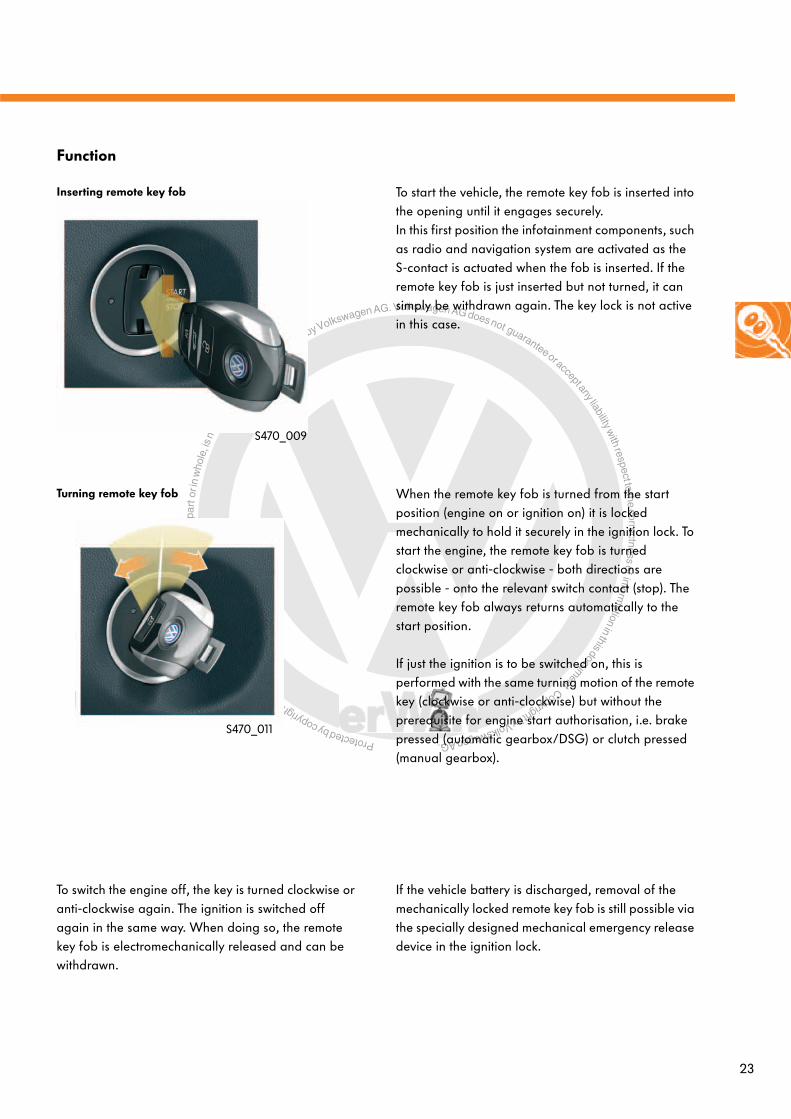
When the remote key fob is turned from the start position (engine on or ignition on) it is locked mechanically to hold it securely in the ignition lock. To start the engine, the remote key fob is turned clockwise or anti-clockwise - both directions are possible - onto the relevant switch contact (stop). The remote key fob always returns automatically to the start position.
If just the ignition is to be switched on, this is performed with the same turning motion of the remote key (clockwise or anti-clockwise) but without the prerequisite for engine start authorisation, i.e. brake pressed (automatic gearbox/DSG) or clutch pressed (manual gearbox).
Turning remote key fob
To switch the engine off, the key is turned clockwise or anti-clockwise again. The ignition is switched off again in the same way. When doing so, the remote key fob is electromechanically released and can be withdrawn.
If the vehicle battery is discharged, removal of the mechanically locked remote key fob is still possible via the specially designed mechanical emergency release device in the ignition lock.
Function
To start the vehicle, the remote key fob is inserted into the opening until it engages securely. In this first position the infotainment components, such as radio and navigation system are activated as the S-contact is actuated when the fob is inserted. If the remote key fob is just inserted but not turned, it can simply be withdrawn again. The key lock is not active in this case.
Inserting remote key fob
S470_009
S470_011

Protected by copyright. C
opying
for p
rivat
e or
com
mer
cial
pur
pose
s, in
par
t or i
n w
hole
, is
not p
erm
itted
unles
s authorise
d by Volkswagen AG. Volkswagen AG does not guarantee or accept any liability with respect to the correctness ofinform
ation in this document.Copyright by Volkswagen AG.
24
Convenience electronics
The area view sensorsThe area view sensors form the basis of the driver assist systems. The Touareg 2011 features several radars and camera sensors that monitor the surrounding area, which is analysed and interpreted using intelligent algorithms.
● The Touareg is equipped at the front with two 77GHz radar sensors with a range of 200m. These are used for the adaptive cruise control (ACC) and Front Scan.
● A multifunctional front camera serves:- to detect vehicles (invisible to radar) - to monitor the area in front of the vehicle when stationary (automatic restart of ACC)- to detect lane information for lane departure warning.- to detect vehicles and other illuminated objects at night for dynamic light assist.
● In the rear area there are two further radar sensors (24 GHz) that scan the traffic situation behind the vehicle. They form the basis for lane change assist, the signals of which are used in addition by ACC and Front Scan.
● To aid parking, the Touareg is equipped with two 4-channel ultrasound systems. The information from the ultrasound sensors is also used for ACC regulation.
Radar, rear
Ultrasoundrear
Radar, front
Multifunctional front camera
Ultrasoundfront
S470_012

Protected by copyright. C
opying
for p
rivat
e or
com
mer
cial
pur
pose
s, in
par
t or i
n w
hole
, is
not p
erm
itted
unles
s authorise
d by Volkswagen AG. Volkswagen AG does not guarantee or accept any liability with respect to the correctness ofinform
ation in this document.Copyright by Volkswagen AG.
25
Driver assist systems
The multifunctional camera systemWith the camera control unit J852, the multifunctional camera forms one assembly unit. With the operating and display protocol (ODP), the camera control unit J852 sends information via the extended CAN data bus to be used by the light assist systems and the lane departure warning system.
If the Touareg is fitted with adaptive cruise control (ACC), the control unit for image processing J851 is also included. J852 receives the image information via a fast LVDS line (Low Voltage Differential Signalling). This control unit sends the safety-relevant signals along the fast FlexRay data bus and supplies the control units for cruise control J428 and J850, which are also located in the FlexRay network, with the details derived from the image information.
To calculate the dive angle of the vehicle about the Y-axis with greater speed and safety, the camera control unit has a dive rate sender at its disposal, which is connected via the extended CAN.
FlexRay
Extended CAN
Data bus diagnostic interface J533
Control unit for image processing J851
Camera control unit J852
LVDS (Low Voltage Differential Signalling)
Dive rate sender G752
S470_016

Protected by copyright. C
opying
for p
rivat
e or
com
mer
cial
pur
pose
s, in
par
t or i
n w
hole
, is
not p
erm
itted
unles
s authorise
d by Volkswagen AG. Volkswagen AG does not guarantee or accept any liability with respect to the correctness ofinform
ation in this document.Copyright by Volkswagen AG.
26
Driver assist systems
The multifunctional front camera
The multifunctional front camera is integrated into the mirror base. It has the following features:
- It is a colour camera with a resolution of 1024 x 512 pixels.
- The range, depending on the system, can be up to 800m.
- The horizontal opening angle is 42 degrees and the vertical angle is 21 degrees.
The camera in the Touareg serves several systems. It supplies image information at different ranges for the following driver assist systems:
- Adaptive cruise control (ACC) with Front Scan with reduced stopping distance 3 (60m)
- Lane departure warning (80m)- Dynamic light assist (DLA) (400/800m)- Traffic sign/marking recognition (later
introduction)
S470_034S470_024
The dive rate sender G752 is located on the rear right (in direction of travel) beneath the bench seat support panel.It provides the vehicle's rate of rotation about the lateral axis (y-axis) and transfers this signal via the extended CAN exclusively to the camera control unit J852.
The dive rate sender G752
The dive angle calculated from this is needed by the camera for the image processing functions.
The dive rate sender is not capable of self-diagnosis and does not have its own diagnosis address. Diagnosis is possible via the camera control unit J852 with address code 85.
S470_022S470_020
Direction of travel

Protected by copyright. C
opying
for p
rivat
e or
com
mer
cial
pur
pose
s, in
par
t or i
n w
hole
, is
not p
erm
itted
unles
s authorise
d by Volkswagen AG. Volkswagen AG does not guarantee or accept any liability with respect to the correctness ofinform
ation in this document.Copyright by Volkswagen AG.
27
The adaptive cruise control Adaptive cruise control, sometimes referred to as automatic cruise control (ACC), with double radar and Front Scan is an enhancement of the conventional cruise control system (CCS).
Description of systemThe adaptive cruise control system keeps the vehicle travelling at a previously selected speed, which the driver can set for open roads at 30-250km/h and for following at 0-250km/h.
The adaptive cruise control system also ensures that a preset distance from the vehicle travelling ahead is safely maintained. In this case, the speed of the vehicle is adapted to the speed of any vehicle travelling ahead. The speed can be set in four stages (from approx. 1 -2.5sec.).Furthermore, the driver has three driving programmes to choose from: "Standard", "Comfort" and "Dynamic".
If the road ahead is clear, the vehicle is accelerated up to the desired speed. If there is a vehicle travelling ahead at a slower speed in the same lane, the system adapts to allow the vehicle to match that speed with a preset distance.
Specifieddistance
Actual distance
Target vehicle detectedDisplay in dash panel insert
Desired speed
S470_003
Lane detection by the camera, route data from the navigation system and detection of stationary vehicles and vehicles travelling ahead by both front radars ensures an improved estimation of which path to follow to continue the route. If a turn signal is activated, the system detects the driver's intention to overtake and improves the system dynamics with consideration for following traffic.
Stop&Go function
If the vehicle travelling ahead slows down to a halt, the Touareg will brake automatically and stop behind the vehicle. If the vehicle ahead resumes its journey within three seconds, the Touareg will follow it likewise automatically. If the stationary period lasts longer than three seconds, the driver can activate a time window of 15 seconds by pressing the RES button in the steering column switch enabling the Touareg to follow the vehicle ahead automatically within this period. With the gap close function (press RES button, both vehicles stationary), the gap to the vehicle ahead can be closed comfortably.

Protected by copyright. C
opying
for p
rivat
e or
com
mer
cial
pur
pose
s, in
par
t or i
n w
hole
, is
not p
erm
itted
unles
s authorise
d by Volkswagen AG. Volkswagen AG does not guarantee or accept any liability with respect to the correctness ofinform
ation in this document.Copyright by Volkswagen AG.
28
Driver assist systems
Front Scan
Front Scan in the Touareg is not just an assist function with a warning that is designed to prevent collision accidents, it also offers, in its third generation, a means of braking the vehicle (also without driver intervention). This contributes towards reducing the accident severity. Under certain conditions (speed-dependent), the system may be able to avoid the accident.This automatic emergency braking function (ANB) is achieved by reduced stopping distance RSD3. It accompanies reduced stopping distance RSD1 and reduced stopping distance RSD2 to form part of Front Scan.
Reduced stopping distance RSD3
Following the warning jolt from reduced stopping distance 2, the system decelerates at a rate of 3m/s2 until a reaction period of has elapsed. If the driver does not brake sufficiently, the system will intervene with additional braking. If the driver does not respond at all, the deceleration rate is increased to 5m/s2. If a collision is unavoidable, the system will initiate emergency braking, providing the following traffic is not put at risk, with maximum deceleration up to 9m/s2. In this instance, an overall speed reduction of 40km/h is engineered to reduce the accident severity. While this increased deceleration is taking place, the following traffic is made aware of the situation by the hazard warning lights (emergency flashing).
Further information about reduced stopping distance RSD1 and RSD2 can be found in self-study programme no. 374 "Traction control and assist systems".
RSD2: Optical/acoustic warningRSD1: PrefillRSD1: Increased sensitivity of brake assist
RSD2: Warning joltRSD1: Highest sensitivity of brake assistRSD3: Deceleration with 3m/s2
RSD3: Deceleration with 5 m/s2
ANB: Emergency braking with 9m/s2
S470_056
Protected by copyright. C
opying
for p
rivat
e or
com
mer
cial
pur
pose
s, in
par
t or i
n w
hole
, is
not p
erm
itted
unles
s authorise
d by Volkswagen AG. Volkswagen AG does not guarantee or accept any liability with respect to the correctness ofinform
ation in this document.Copyright by Volkswagen AG.
29
The adaptive cruise control system is a functional highlight. A combined system of up to 27 control units provides even greater comfort and safety. A new feature of the adaptive cruise control system in the Touareg 2011 is not just that this assist system is one function spread over several control units but also that other assist systems with completely different tasks can be included in the operation.
In this instance, for example, these are the radar sensors from the lane departure warning, the multifunctional camera system, which is used, among other things, to keep the vehicle in lane, and also the ultrasound sensors from park distance control. All of the components and systems mentioned serve as a means of monitoring the area in front of and behind the vehicle and identifying potential obstacles. They are described briefly as follows.
System design
Ultrasound sensors
The signals from the ultrasound sensors are used to resume travel on the new Stop&Go function.
Multifunctional camera system
The multifunctional camera system serves as a supplier of redundant signals to determine plausibility of the signals from the front radar sensors. As before, the system bridges the detection gap between ultrasound sensors and radar sensors.
Using the camera with its 60m range for the ACC and RSD3 functions and the navigation data (with unrestricted "view"), an improved forecast of what path the road is taking and information about the number of lanes is provided in addition to reduced neighbouring lane interference. Thanks to the colour camera, coloured markings are detected more easily (even different coloured road markings overseas).

Protected by copyright. C
opying
for p
rivat
e or
com
mer
cial
pur
pose
s, in
par
t or i
n w
hole
, is
not p
erm
itted
unles
s authorise
d by Volkswagen AG. Volkswagen AG does not guarantee or accept any liability with respect to the correctness ofinform
ation in this document.Copyright by Volkswagen AG.
30
Driver assist systems
Front radar sensors
The front radar sensors are located next to the fog lamps. They are 3rd generation radar sensors with the following features:
● Integrated in the sensor are 4 radar aerial units.● They work based on the long range sensor
principle with a sender frequency of 77GHz.● The installed sensor heater works in a temperature
range of -5°C to +5°C.● The radar sensor range is 200m. ● The horizontal opening angle is 40 degrees.
With this new generation of radar sensors, the whole width of a 3 lane road can be scanned even from a distance of approx. 30 m.
S470_036
S470_028
4 aerial units per radar sensor
Sender
Receiver
S470_002

Protected by copyright. C
opying
for p
rivat
e or
com
mer
cial
pur
pose
s, in
par
t or i
n w
hole
, is
not p
erm
itted
unles
s authorise
d by Volkswagen AG. Volkswagen AG does not guarantee or accept any liability with respect to the correctness ofinform
ation in this document.Copyright by Volkswagen AG.
31
Detection of lane change
Detected rear viewsof vehicles travelling ahead
Distances to detectedlane boundaries
The multifunctional camera system detects an impending lane change by the vehicle travelling ahead as it approaches its lane boundaries.
Stored in the camera system are various characteristics, which enable the system to differentiate between car, truck or motorbike. The lane change is detected irrespective of whether the vehicle travelling ahead enters or exits the same lane as the camera system.
This information is transmitted to the ACC system, adopted by it in its calculation algorithm and serves as a means of determining, with greater precision, what is happening ahead.
Obstacle detection in close proximity
Monitoring following traffic
The information from the multifunctional camera system and the ultrasound sensors for obstacle detection is required mainly for the close proximity (within 5m) to make it easier to resume travel. In this range, the radar sensors are not capable of detecting the whole area due to their radiation characteristics and their opening angle.
If a "no following traffic" message has been issued, the rear sensors enable Front Scan to increase the deceleration rate of 3m/s2 to maximum 9m/s2 during brake intervention following a driver warning.
S470_005
System functions of ACC

Protected by copyright. C
opying
for p
rivat
e or
com
mer
cial
pur
pose
s, in
par
t or i
n w
hole
, is
not p
erm
itted
unles
s authorise
d by Volkswagen AG. Volkswagen AG does not guarantee or accept any liability with respect to the correctness ofinform
ation in this document.Copyright by Volkswagen AG.
32
Driver assist systems
Lane departure warning
Lane departure warning helps the driver keep the vehicle in lane. The system comprises a camera in the roof module holder, the displays in the dash panel insert and a vibration motor in the steering wheel. With the aid of the camera (range for this function 80m), the lane boundary markings are detected. If the vehicle appears to be departing the lane unintentionally, the driver's attention is drawn back to the traffic situation by means of a steering wheel vibration.
Area of use
● Motorways and major roads● Activation speed 65km/h to 250km/h ● During deceleration, the system remains active up
to 60km/h
● Curve radius > 250m● Lane widths of 2.5m to 5.0m● A lane marking on one side is sufficient to detect
the lane
Poor conditions, such as insufficient road markings, dirty or snow-covered road surfaces, excessively narrow lanes or even ambivalent road markings, as is often the case when road works are being carried out on the motorway, lead to the system being temporarily incapable of providing a warning.
S470_013

Protected by copyright. C
opying
for p
rivat
e or
com
mer
cial
pur
pose
s, in
par
t or i
n w
hole
, is
not p
erm
itted
unles
s authorise
d by Volkswagen AG. Volkswagen AG does not guarantee or accept any liability with respect to the correctness ofinform
ation in this document.Copyright by Volkswagen AG.
33
Lane departure warning switched on and in active mode
The lane departure warning system is switched on and off with the button for driver assist systems on the front of the turn signal lever and by activating the buttons in the menu of the dash panel insert. If the lane departure warning system detects clear road markings within its system limitations, it changes from a passive (at least one condition has not been met) to an active operating mode.
The control lamp indicates the operating status of the lane departure warning system.
Operation
lane departure warning switched off
lane departure warning switched on and in passive mode
S470_072
The lane departure warning control lamp
The driver can choose from three different warning levels via the touchstone of the infotainment system:
● Early warning level: The virtual boundary is set approx. 20cm before the lane marking.
● Normal warning level: The virtual boundary is the same as the lane marking.
● Late warning level: The virtual boundary is set approx. 20cm after the lane marking.
When the virtual boundary is driven over, a warning is issued.
Adjusting warning levelS470_074
Late warning level
Normal warning level
Early warning level
Switching on and off

Protected by copyright. C
opying
for p
rivat
e or
com
mer
cial
pur
pose
s, in
par
t or i
n w
hole
, is
not p
erm
itted
unles
s authorise
d by Volkswagen AG. Volkswagen AG does not guarantee or accept any liability with respect to the correctness ofinform
ation in this document.Copyright by Volkswagen AG.
34
Driver assist systems
System design
Steering vibration motor
The steering vibration motor V331 is located in the bottom spoke of the steering wheel and is actuated by the signal from the camera control unit J852 via CAN and by the steering column electronics control unit via LIN.
The driver can choose from three vibration levels with different frequencies:
- Weak level – 29hz- Medium level – 34hz- Strong level – 44hz
These levels are adjusted via the touchscreen of the infotainment system.
The different frequencies are achieved by PWM signal actuation to the steering wheel vibration motor E221.
S470_063
S470_076Steering vibration motor
KeyE221 Operating unit in steering wheelJ527 Steering column electronics control unitJ533 Data bus diagnostic interfaceJ852 Camera control unitV331 Steering vibration motor
h Extended CAN data busk Convenience CAN data busL LIN data bus
NetworkingV331
E221
J852
J527
J533
PWM
L
k
hS470_120

Protected by copyright. C
opying
for p
rivat
e or
com
mer
cial
pur
pose
s, in
par
t or i
n w
hole
, is
not p
erm
itted
unles
s authorise
d by Volkswagen AG. Volkswagen AG does not guarantee or accept any liability with respect to the correctness ofinform
ation in this document.Copyright by Volkswagen AG.
35
System function
When the lane departure warning system is switched on, the system starts to scan and evaluate the path the road follows in front of the vehicle via the camera. If the vehicle gets close to a recognised boundary line and there is a threat of it departing the lane, the driver is warned by a vibration in the steering wheel.
The system only warns once. A second warning is only issued if the vehicle has moved sufficiently away from the relevant boundary line and has then approached it again. In this way, it is possible to avoid continual warnings while driving parallel to a road marking.
If, while the system is active, a turn signal is activated before a boundary line is driven over, the warning is suppressed as the system assumes that the lane departure is intentional.
Aside from the steering wheel vibration, the driver of the new Touareg can see a visual representation of detected and violated (driven over) boundary lines in the display of the dash panel insert.
System messages
Active mode:- Road marking detected on left
and right
Active mode:- Road marking detected on right- Road marking not detected on
left
Passive mode:- Road marking not detected on
left and right
Active mode:- Road marking detected on left
and right- Warning threshold on right
exceeded
Active mode:- Road marking detected on right- Road marking not detected on
left- Warning threshold on right
exceeded
S470_062
S470_064
S470_066
S470_068
S470_070
A warning is only issued in the case where a road marking is detected on one side if the boundary on that side is violated.

Protected by copyright. C
opying
for p
rivat
e or
com
mer
cial
pur
pose
s, in
par
t or i
n w
hole
, is
not p
erm
itted
unles
s authorise
d by Volkswagen AG. Volkswagen AG does not guarantee or accept any liability with respect to the correctness ofinform
ation in this document.Copyright by Volkswagen AG.
36
Driver assist systems
The dynamic light assistThe dynamic light assist (DLA) from Volkswagen (also designated "masked permanent main beam") is debuted in the new Touareg.
It is based on the already existing systems dynamic cornering light and headlight range control.
Function
Example of change in light distribution of headlight due to automatic detection of approaching objects with activated/recognisable lighting.
Illumination without object in opposing lane
Illumination with object in opposing lane - distance to object far
Illumination with object in opposing lane - distance to object medium
Illumination when passing an object in the opposing laneIn the final approaching phase, the "masked main beam" from the left headlight is equal to the dipped beam position.
With the dynamic light assist function, the road and edges of the road are illuminated to maximum effect while, at the same time, preventing any dazzling of vehicles travelling ahead in the same and opposite direction. The DLA is therefore currently the most innovative development level for headlight systems with variable light distribution.
S470_058
S470_058a to 058d

Protected by copyright. C
opying
for p
rivat
e or
com
mer
cial
pur
pose
s, in
par
t or i
n w
hole
, is
not p
erm
itted
unles
s authorise
d by Volkswagen AG. Volkswagen AG does not guarantee or accept any liability with respect to the correctness ofinform
ation in this document.Copyright by Volkswagen AG.
37
Example of change in light distribution of headlight due to automatic detection of objects travelling ahead with activated/recognisable lighting.
Illumination without object in own lane
Illumination with object in own lane - distance to object far
Illumination with object in own lane - distance to object medium
Illumination with object in own lane - distance to object closeIn the final approaching phase, the "masked main beam" from the right headlight is equal to the dipped beam position.
Activation conditions:
- Light switch in "Auto" position- Main beam actuated- DLA switched on via touchscreen of infotainment system.- Dark (signal from rain and light sensor G397)- Speed > 60km/h
S470_060
S470_060a to 060d

Protected by copyright. C
opying
for p
rivat
e or
com
mer
cial
pur
pose
s, in
par
t or i
n w
hole
, is
not p
erm
itted
unles
s authorise
d by Volkswagen AG. Volkswagen AG does not guarantee or accept any liability with respect to the correctness ofinform
ation in this document.Copyright by Volkswagen AG.
38
Networking
The dynamic light assist is based on the intelligent interplay of multifunctional front camera and camera control unit J852, image processing software and top Xenon headlight.
With the front camera, vehicles travelling ahead (camera range 400m) and those approaching from the opposite side (camera range 800m) are detected providing their lights are on. This information is digitally evaluated and the exact position and width of the detected vehicles is determined. The system also distinguishes between street lamps, traffic lights or reflections from side marker posts. This information is sent to the control unit for cornering light and headlight range control. Together with other vehicle information, such as speed, steering wheel angle or general lighting conditions, the optimal light distribution is thereby calculated automatically and depending on the situation and then sent to the headlight control units. These are installed directly onto the headlights. They have the same design and the same part number. The control units can determine whether they control the left or right headlight by means of the connector coding.
Based on the calculated light distribution, a special roller-type mask is now moved between the light source and projection lens in the top Xenon headlight. This prevents anyone from being dazzled, i.e. other traffic users are kept out of the light distribution.
Driver assist systems
KeyE1 Light switchG752 Dive rate senderJ285 Control unit in dash panel insertJ519 Onboard supply control unitJ527 Steering column electronics control unitJ533 Data bus diagnostic interfaceJ667 Power output module for left headlightJ668 Power output module for right headlightJ685 Display unit for front information display
and operating unit control unitJ745 Cornering light and headlight range control unitJ794 Control unit 1 for information electronicsJ852 Camera control unit
b Display and operation CAN data bush Extended CAN data busk Convenience CAN data busL LIN data busm MOST data bus
J667
hJ668
J745
k
b
L
J852
J285
J533
E1
J519
J527
J794
LVDS
m
J685S470_118
G752

Protected by copyright. C
opying
for p
rivat
e or
com
mer
cial
pur
pose
s, in
par
t or i
n w
hole
, is
not p
erm
itted
unles
s authorise
d by Volkswagen AG. Volkswagen AG does not guarantee or accept any liability with respect to the correctness ofinform
ation in this document.Copyright by Volkswagen AG.
39
Top Xenon headlight
The function of the dynamic light assist is realised by the additional, rotating, roller-type mask (shutter) between the reflector with the xenon burner and the lens. In connection with intelligent actuation of the left and right headlight, this additional masking geometry allows light to be masked only when it could dazzle others.
Even with the DLA switched off, the mask ensures that the dipped beam and main beam functions can be activated. Furthermore, in the dipped beam position it allows the functions urban light, main road light and motorway light.
The top Xenon headlight in the Touareg 2011 is the first headlight with permanently masked main beam.
Roller-type mask
S470_038
S470_037
S470_078 S470_080
Xenon burner
Reflector
Lens

Protected by copyright. C
opying
for p
rivat
e or
com
mer
cial
pur
pose
s, in
par
t or i
n w
hole
, is
not p
erm
itted
unles
s authorise
d by Volkswagen AG. Volkswagen AG does not guarantee or accept any liability with respect to the correctness ofinform
ation in this document.Copyright by Volkswagen AG.
40
Driver assist systems
Area View This driver assist function is debuted at Volkswagen in the Touareg 2011. Area View is a camera-based area capture system and is an enhancement of the reversing camera familiar from the A and B class (Rear Assist). While the reversing camera covers the area behind the vehicle, Area View allows the driver to see the entire area around the vehicle. It offers the driver numerous views and setting modes that he/she can specifically select depending on the traffic situation and according to the information he/she requires.
Design of Area View system
Visual rangeof rear camera
R246
Visual rangeof front camera
R243
Visual rangeof left mirrorcamera R244
Visual rangeof right mirrorcamera R245
Capturing the view around the vehicle is achieved by four cameras that are integrated cleverly within the vehicle. The front camera is located in the front grille, the rear camera is in the handle of the rear lid and the side cameras are installed underneath the side mirrors.
The cameras have wide-angle lenses and capture the whole area around the vehicle, thus enabling areas to be viewed that are either difficult to see or cannot be seen at all. Since the camera capture areas overlap, an accurate and realistic optical transition between the visual ranges of neighbouring cameras can be created (so-called bird's eye view with complete area capture).
The system has the diagnosis address of the reversing camera system (6C).
Area view camera control unit J928
Control unit 1 for information electronics J794 anddisplay unit for front information display
and operating unit control unit J685
S470_010

Protected by copyright. C
opying
for p
rivat
e or
com
mer
cial
pur
pose
s, in
par
t or i
n w
hole
, is
not p
erm
itted
unles
s authorise
d by Volkswagen AG. Volkswagen AG does not guarantee or accept any liability with respect to the correctness ofinform
ation in this document.Copyright by Volkswagen AG. 41
J393
The cameras are connected via HSD wires (High Speed Data) to the area view camera control unit. These wires are used to supply power to the cameras, to control them and to transfer video signals per LVDS (Low Voltage Differential Signalling).
The connection between the area view camera control unit and the information electronics control unit 1 is by means of coaxial cable (CVBS - composite video signal). The data transfer rate of the CVBS connection is approx. 6MBit/s.
The area view camera control unit relies on a wide range of signals from other control units. The accrued signals are just displayed optically by the area view camera control unit without having any functional influence or effect on other systems (e.g. display of dynamic steering angle dependent guidelines).
Networking
KeyD Ignition/starter switchE221 Operating unit in steering wheelG85 Steering angle senderG397 Rain and light sensorG419 ESP sensor unitJ104 ABS control unitJ217 Automatic gearbox control unitJ285 Control unit in dash panel insertJ345 Trailer detector control unitJ386 Driver door control unitJ387 Front passenger door control unitJ388 Rear left door control unitJ389 Rear right door control unitJ393 Convenience system central control unitJ400 Wiper motor control unitJ446 Parking aid control unit J519 Onboard supply control unitJ527 Steering column electronics control unitJ533 Data bus diagnostic interfaceJ685 Display unit for front information
from display and operating unit
J794 Control unit 1 for information electronicsJ928 Area view camera control unitR* Radio RCD 550 (introduced later,
excluded with J794)R243 Front area view cameraR244 Left area view cameraR245 Right area view cameraR246 Rear area view camera
a Powertrain CAN data busb Display and operation CAN data busfw Chassis CAN data busk Convenience CAN data busL LIN data busm MOST data bus
J794m
J685
CVBS
LVDS
bfw
R243
R245
R246
R244
k
a
L
G85
J104
J217
J345
J446
J519
J527
J533
J928
J285
S470_122
LVDS
R*G419
J387
J386
J389
J388
D
J400
G397
E221
L
L
L
L
Protected by copyright. C
opying
for p
rivat
e or
com
mer
cial
pur
pose
s, in
par
t or i
n w
hole
, is
not p
erm
itted
unles
s authorise
d by Volkswagen AG. Volkswagen AG does not guarantee or accept any liability with respect to the correctness ofinform
ation in this document.Copyright by Volkswagen AG.
42
Driver assist systems
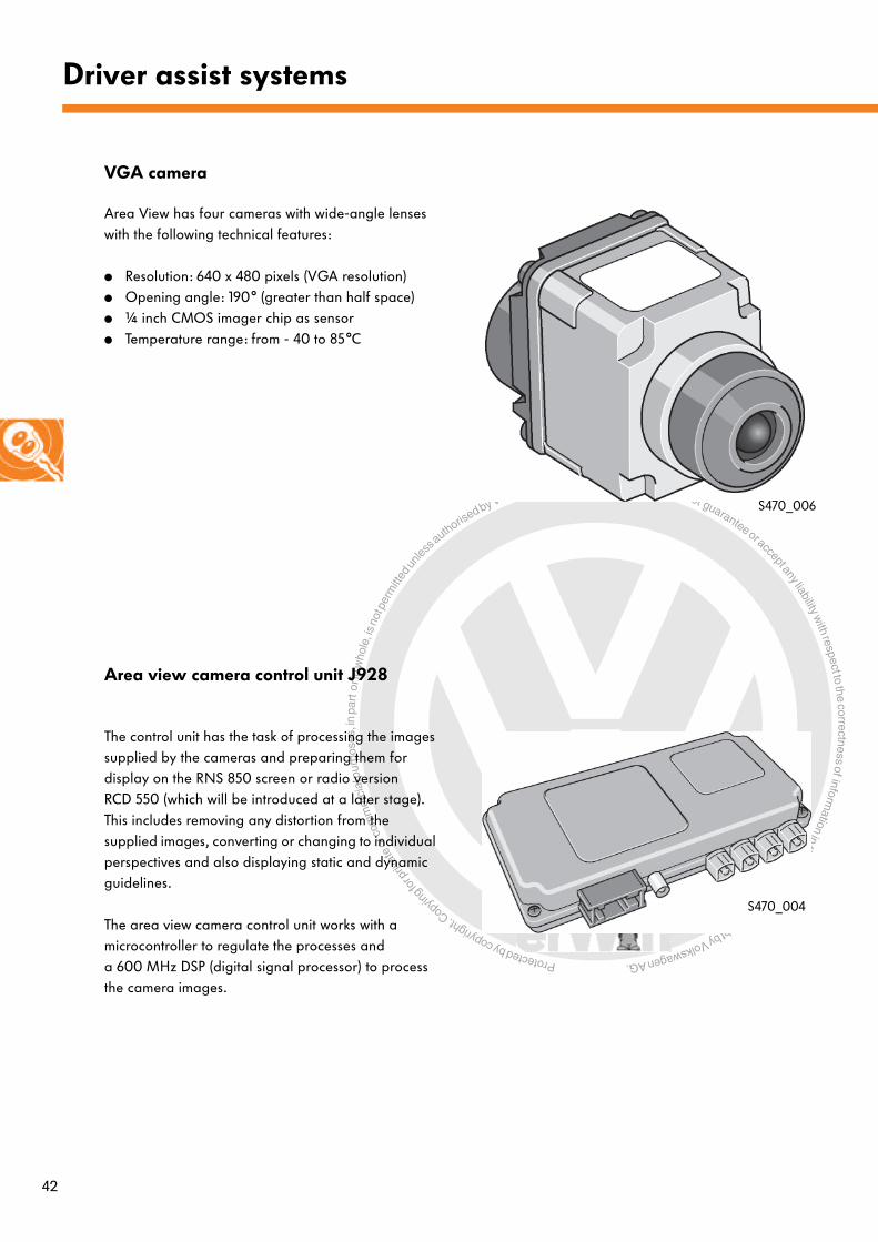
VGA camera
Area view camera control unit J928
The control unit has the task of processing the images supplied by the cameras and preparing them for display on the RNS 850 screen or radio version RCD 550 (which will be introduced at a later stage). This includes removing any distortion from the supplied images, converting or changing to individual perspectives and also displaying static and dynamic guidelines.
The area view camera control unit works with a microcontroller to regulate the processes and a 600 MHz DSP (digital signal processor) to process the camera images.
Area View has four cameras with wide-angle lenses with the following technical features:
● Resolution: 640 x 480 pixels (VGA resolution)● Opening angle: 190° (greater than half space)● ¼ inch CMOS imager chip as sensor ● Temperature range: from - 40 to 85°C
S470_004
S470_006
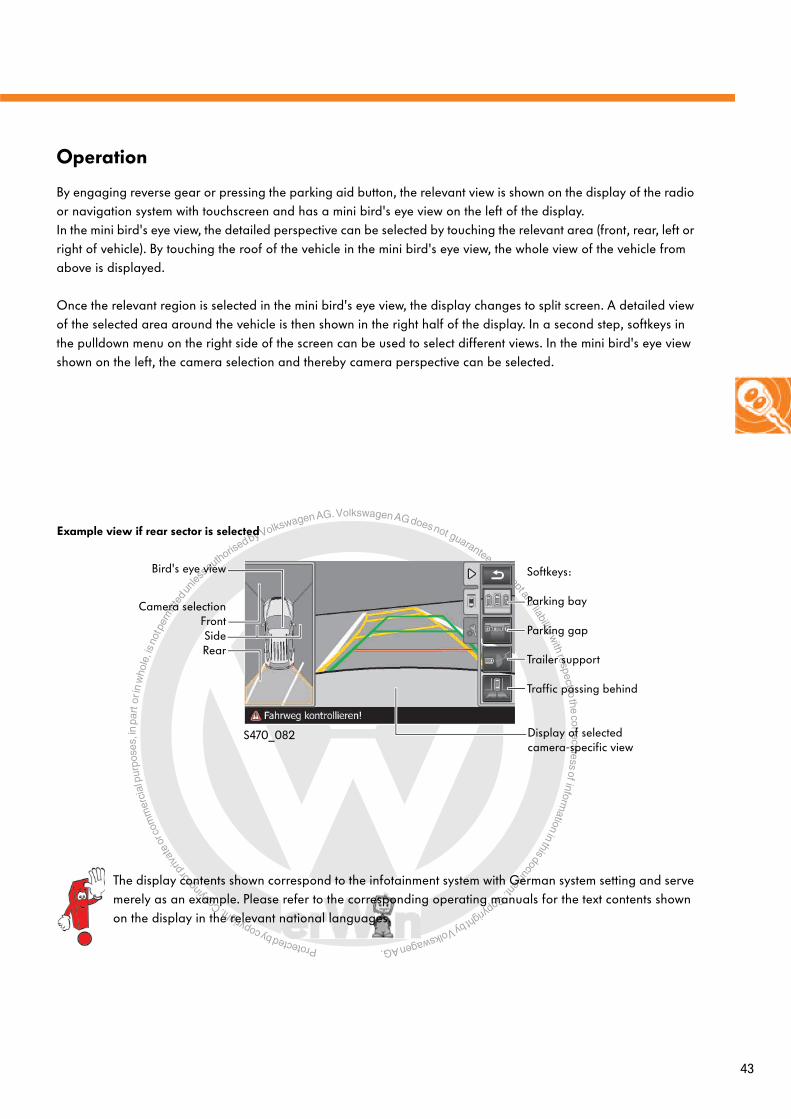
Protected by copyright. C
opying
for p
rivat
e or
com
mer
cial
pur
pose
s, in
par
t or i
n w
hole
, is
not p
erm
itted
unles
s authorise
d by Volkswagen AG. Volkswagen AG does not guarantee or accept any liability with respect to the correctness ofinform
ation in this document.Copyright by Volkswagen AG.
43
Operation
By engaging reverse gear or pressing the parking aid button, the relevant view is shown on the display of the radio or navigation system with touchscreen and has a mini bird's eye view on the left of the display. In the mini bird's eye view, the detailed perspective can be selected by touching the relevant area (front, rear, left or right of vehicle). By touching the roof of the vehicle in the mini bird's eye view, the whole view of the vehicle from above is displayed.
Once the relevant region is selected in the mini bird's eye view, the display changes to split screen. A detailed view of the selected area around the vehicle is then shown in the right half of the display. In a second step, softkeys in the pulldown menu on the right side of the screen can be used to select different views. In the mini bird's eye view shown on the left, the camera selection and thereby camera perspective can be selected.
Example view if rear sector is selected
Bird's eye view
Camera selectionFrontSideRear
Display of selected camera-specific view
Softkeys:
Parking bay
Parking gap
Trailer support
Traffic passing behind
The display contents shown correspond to the infotainment system with German system setting and serve merely as an example. Please refer to the corresponding operating manuals for the text contents shown on the display in the relevant national languages.
S470_082
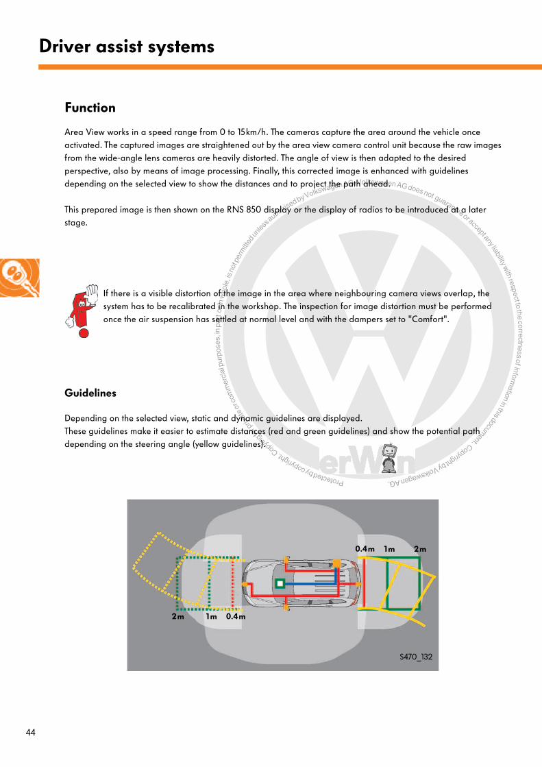
Protected by copyright. C
opying
for p
rivat
e or
com
mer
cial
pur
pose
s, in
par
t or i
n w
hole
, is
not p
erm
itted
unles
s authorise
d by Volkswagen AG. Volkswagen AG does not guarantee or accept any liability with respect to the correctness ofinform
ation in this document.Copyright by Volkswagen AG.
44
Driver assist systems
Function
Area View works in a speed range from 0 to 15km/h. The cameras capture the area around the vehicle once activated. The captured images are straightened out by the area view camera control unit because the raw images from the wide-angle lens cameras are heavily distorted. The angle of view is then adapted to the desired perspective, also by means of image processing. Finally, this corrected image is enhanced with guidelines depending on the selected view to show the distances and to project the path ahead.
This prepared image is then shown on the RNS 850 display or the display of radios to be introduced at a later stage.
Guidelines
Depending on the selected view, static and dynamic guidelines are displayed. These guidelines make it easier to estimate distances (red and green guidelines) and show the potential path depending on the steering angle (yellow guidelines).
0.4m1m2m
0.4m 1m 2m
S470_132
If there is a visible distortion of the image in the area where neighbouring camera views overlap, the system has to be recalibrated in the workshop. The inspection for image distortion must be performed once the air suspension has settled at normal level and with the dampers set to "Comfort".

Protected by copyright. C
opying
for p
rivat
e or
com
mer
cial
pur
pose
s, in
par
t or i
n w
hole
, is
not p
erm
itted
unles
s authorise
d by Volkswagen AG. Volkswagen AG does not guarantee or accept any liability with respect to the correctness ofinform
ation in this document.Copyright by Volkswagen AG.
45
"Cross traffic" view
This function allows the driver to look 90 degrees to the left and right from the front point of the vehicle, i.e. basically to look around the corner, to assess the traffic situation. Despite the fact that the driver is sitting in the vehicle about 2 metres behind the front camera, this system now allows him/her to see what is happening ahead on the left and right. Area View supports the driver here at exits that are difficult to see and in narrow roads.
For the "rear cross traffic" view, the rear camera is used. It allows the driver to see what is happening from the rearmost point of the vehicle.
Bird's eye view
From the four camera images, the control unit calculates an overall view of the area surrounding the vehicle as seen from above through a virtual camera. A high quality image is generated here and particular attention is given to optimising the transitions between the four camera views. In this view, a silhouette of the vehicle as seen from above is superimposed. The driver is thereby allowed to see the area around the vehicle from a bird's perspective, also referred to as bird's eye view.
Situation
Display view
Display view
S470_021
S470_086
Display views
S470_084

Protected by copyright. C
opying
for p
rivat
e or
com
mer
cial
pur
pose
s, in
par
t or i
n w
hole
, is
not p
erm
itted
unles
s authorise
d by Volkswagen AG. Volkswagen AG does not guarantee or accept any liability with respect to the correctness ofinform
ation in this document.Copyright by Volkswagen AG.
46
Driver assist systems
"Parking bay" viewSituation
Display view
This view supports the driver when driving forwards or backwards into a parking space, whereby the front camera or rear camera is used respectively.
When parking forwards, the view is activated by pressing the park distance control button. When parking backwards, the view is activated by engaging reverse gear.
"Left and right side" view
With this view, side cameras support the driver, e.g. when parking or on offroad tracks. Static guidelines indicate to the driver the distance to an obstacle, e.g. a curb.
Both side views can also be activated simultaneously via the side softkeys.
Situation
Display view
S470_041
S470_088
S470_045
S470_090

Protected by copyright. C
opying
for p
rivat
e or
com
mer
cial
pur
pose
s, in
par
t or i
n w
hole
, is
not p
erm
itted
unles
s authorise
d by Volkswagen AG. Volkswagen AG does not guarantee or accept any liability with respect to the correctness ofinform
ation in this document.Copyright by Volkswagen AG.
47
"Trailer support" view
This view makes it easier for the driver to hitch up a trailer. The rear camera is used for this function. The driver sees the area behind the vehicle from above. Green guidelines in the image provide a means of assessing the distance from the hitch to trailer. A yellow line shows the driver in which direction the vehicle will move with this steering angle. Hitching up the trailer to the vehicle is thereby optically supported.
To display this view, it is necessary to toggle in the menu. Simply deploying the trailer hitch or hitching up the trailer will not result in the perspective being selected.
"Offroad" display
This view supports the driver when driving offroad and if difficult obstacles are encountered by displaying the area directly in front of the vehicle from a bird's eye view.
Situation
Display view
Situation
Display view
S470_025
S470_092
S470_029
S470_094
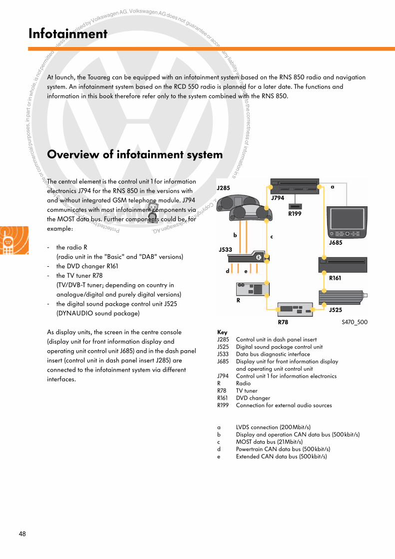
Protected by copyright. C
opying
for p
rivat
e or
com
mer
cial
pur
pose
s, in
par
t or i
n w
hole
, is
not p
erm
itted
unles
s authorise
d by Volkswagen AG. Volkswagen AG does not guarantee or accept any liability with respect to the correctness ofinform
ation in this document.Copyright by Volkswagen AG.
48
Overview of infotainment system
Infotainment
At launch, the Touareg can be equipped with an infotainment system based on the RNS 850 radio and navigation system. An infotainment system based on the RCD 550 radio is planned for a later date. The functions and information in this book therefore refer only to the system combined with the RNS 850.
The central element is the control unit 1 for information electronics J794 for the RNS 850 in the versions with and without integrated GSM telephone module. J794 communicates with most infotainment components via the MOST data bus. Further components could be, for example:
- the radio R(radio unit in the "Basic" and "DAB" versions)
- the DVD changer R161- the TV tuner R78
(TV/DVB-T tuner; depending on country in analogue/digital and purely digital versions)
- the digital sound package control unit J525(DYNAUDIO sound package)
As display units, the screen in the centre console (display unit for front information display and operating unit control unit J685) and in the dash panel insert (control unit in dash panel insert J285) are connected to the infotainment system via different interfaces.
KeyJ285 Control unit in dash panel insertJ525 Digital sound package control unitJ533 Data bus diagnostic interfaceJ685 Display unit for front information display
and operating unit control unitJ794 Control unit 1 for information electronicsR Radio R78 TV tunerR161 DVD changerR199 Connection for external audio sources
a LVDS connection (200Mbit/s)b Display and operation CAN data bus (500kbit/s)c MOST data bus (21Mbit/s)d Powertrain CAN data bus (500kbit/s)e Extended CAN data bus (500kbit/s)
J794
R
J685
R161
J525
J285
J533
R78
a
b c
R199
d e
S470_500

Protected by copyright. C
opying
for p
rivat
e or
com
mer
cial
pur
pose
s, in
par
t or i
n w
hole
, is
not p
erm
itted
unles
s authorise
d by Volkswagen AG. Volkswagen AG does not guarantee or accept any liability with respect to the correctness ofinform
ation in this document.Copyright by Volkswagen AG.
49
Further information about the infotainment system can be found in self-study programme no. 473 "Infotainment in the Touareg 2011".
The DYNAUDIO sound system
The central element of the DYNAUDIO sound system is a 620 watt amplifier with surround control (digital sound package control unit J525).It is fitted in the luggage compartment near the left-hand wheel housing and has 10 output stages for connecting a maximum of 12 loudspeakers. The amplifier communicates with the infotainment system via the MOST data bus.
A microphone built into the roof module detects the noises in the interior. These noises are analysed by the amplifier electronics and the playback signal is then adjusted depending on the frequency and sound level. This process is called automatic playback signal adjustment.
The surround control (Dolby 5.1, if supported by the data medium) allows you to set up an optimum surround sound, which faithfully reproduces, for example, concert hall acoustics, in relation to your position inside the vehicle.
Keya 60mm treble
loudspeakerb 100mm mid-range
loudspeaker cone
c 200mm bassloudspeaker
d 50mm trebleloudspeaker
J525 Digital sound package control unit
R74 Internal microphone(in roof module)
2 loudspeakers in centre of dash panel
5 loudspeakers on right-hand side of vehicle5 loudspeakers on left-hand side of vehicle
aa
b b
c
c
ad
c
c
a b
MOST data bus
J525
R74
S470_046

Protected by copyright. C
opying
for p
rivat
e or
com
mer
cial
pur
pose
s, in
par
t or i
n w
hole
, is
not p
erm
itted
unles
s authorise
d by Volkswagen AG. Volkswagen AG does not guarantee or accept any liability with respect to the correctness ofinform
ation in this document.Copyright by Volkswagen AG.
50
Glossary
ABSAnti-lock braking systemCounteracts potential locking of the wheels when the vehicle is braked hard by reducing brake pressure.
ACCAdaptive cruise control, also called automatic cruise control (ACC), is an enhanced version of the conventional cruise control system (CCS).
ANBAutomatic emergency braking
AQSAir quality sensor
RSDReduced stopping distance
ODPThe operating and display protocol ODP is used for communication between function control units and operating and display control units. ODP consistently separates the function from the display and control.
BCMBody control module In the Touareg, either the onboard supply control unit J519 (BCM1) or the convenience system control unit J393 (BCM2) is meant.
BEMBattery energy management
BluetoothAn industry standard developed by the Bluetooth Special Interest Group (SIG) for wireless transmission between devices over short distances.
CANThe controller area network is an asynchronous, serial bus system and belongs to the field buses.
CH/LHComing home and leaving home Coming home is a function that supports the driver when arriving at his/her home destination by allowing the headlights to stay on for a certain time when the vehicle is exited before switching off automatically. The purpose of this is to illuminate the path to the front door, i.e. to add an element of convenience to coming home, and also to improve the vehicle’s visibility when exiting. On some vehicles, the lights are also switched on when the vehicle is unlocked with the remote key fob in order to light up the path from the front door to the car. This function is called leaving home.
DSGDual clutch gearbox
DVDDigital Versatile/Video Discis a further development of the optical storage medium with a storage capacity of 4.7 GB; with one-sided single layered DVDs (single layer DVD, DVD±R, DVD±RW) and 8.5 GB; on double-sided, double layered DVDs (dual/double layered, DVD±R-DL, DVD-RW±DL)
ATAAnti-theft alarm system
ESLElectric steering column lock
Protected by copyright. C
opying
for p
rivat
e or
com
mer
cial
pur
pose
s, in
par
t or i
n w
hole
, is
not p
erm
itted
unles
s authorise
d by Volkswagen AG. Volkswagen AG does not guarantee or accept any liability with respect to the correctness ofinform
ation in this document.Copyright by Volkswagen AG.
51
ESPElectronic stabilisation programme The electronic stabilisation programme is a driver assist system that counteracts skidding through targeted braking of individual wheels (also electronic stability program).
EILElectronic ignition lock
CVBSComposite video, blanking and synchronisation signalThis is also referred to colloquially as "colour TV".
FlexRayFlexRay is a serial, deterministic and fault-tolerant field bus system for use in the automobile.
GPSGlobal positioning satellite systemThis was originally a military satellite-supported, global orientation and localisation system.
GSMGlobal system for mobile communicationsStandard for digital mobile telecommunications network that is used mainly for telephony but also finds application in data transfer and short messaging (SMS).
HSDHigh speed data
IRMInterior monitoring
CPComponent protection
LEDLuminescent diode, or LED for Light Emitting Diode
LINLocal interconnect networkThe local interconnect network (also referred to as LIN data bus) is the specification for a serial communication system. It was developed especially for the low cost communication of intelligent sensors and actuators in motor vehicles, is based on a single wire bus and can be classified as field buses.
LVDSLow voltage differential signalingThis is an interface standard for high speed data transfer.
MDFMasked permanent main beam
MOSTMedia-oriented systems transportThe MOST bus is a serial bus system for transferring audio, video, voice and data signals via fibre-optic cable.
ECUEngine control unit
NMNetwork management
P-modeProduction mode
PR numberProduction numberThis serves to identify the components that are installed. It always has three digits and can be gleaned from the customer service data sticker in the luggage compartment and the service booklet.

Protected by copyright. C
opying
for p
rivat
e or
com
mer
cial
pur
pose
s, in
par
t or i
n w
hole
, is
not p
erm
itted
unles
s authorise
d by Volkswagen AG. Volkswagen AG does not guarantee or accept any liability with respect to the correctness ofinform
ation in this document.Copyright by Volkswagen AG.
52
Glossary
PSRPanoramic sliding roof
PWM signalPulse-width modulated signal
RES buttonResume button
HWSHeadlight washer system
TFTThin-film transistor (type of field-effect transistor)
TFT displayThin-film transistor display;flat screen
UGDOUniversal garage door opener
ESIExtended service interval
Protected by copyright. C
opying
for p
rivat
e or
com
mer
cial
pur
pose
s, in
par
t or i
n w
hole
, is
not p
erm
itted
unles
s authorise
d by Volkswagen AG. Volkswagen AG does not guarantee or accept any liability with respect to the correctness ofinform
ation in this document.Copyright by Volkswagen AG.
53
Test yourself
1. What type of structure do the device connections have in the MOST bus of the Touareg 2011 to assure shared data exchange?
a) Ring topology
b) Star topology
c) Bus topology
d) Mixed topology
Which answer is correct?
One or several of the answers could be correct.
2. When does reduced stopping distance RSD3 occur?
a) After emergency braking
b) After a warning jolt from reduced stopping distance 2
c) During advance warning when the braking system is precharged
3. How is the dynamic light assist function realised in the top Xenon headlight of the Touareg 2011?
a) By a shutter with three different masking plates between the reflector with xenon burner and the lens
b) By a curved plate that can be adjusted so that the areas are masked off
c) By an additional, rotating roller-type mask between the reflector with xenon burner and the lens

Protected by copyright. C
opying
for p
rivat
e or
com
mer
cial
pur
pose
s, in
par
t or i
n w
hole
, is
not p
erm
itted
unles
s authorise
d by Volkswagen AG. Volkswagen AG does not guarantee or accept any liability with respect to the correctness ofinform
ation in this document.Copyright by Volkswagen AG.
54
Test yourself
5. How is the area around the vehicle captured by the "Area View" function?
a) By four cameras with wide-angle lenses, two radar sensors at the front and rear respectively and also ultrasound sensors at the front and rear
b) By four cameras with wide-angle lenses
c) By a multifunctional front camera, two radar sensors at the front and two radar sensors at the rear as well as ultrasound sensors at the front and rear
4. What is the purpose of lane departure warning?
a) It supports fatigued drivers by keeping the vehicle within the detected lane by means of independent, active steering intervention with the aid of the electromechanical power steering's full steering torque.
b) It helps the driver keep the vehicle in lane. If the vehicle threatens to depart from the calculated virtual lane, lane departure warning applies limited, corrective steering torque. If this measure is not sufficient, an acoustic and optical warning and a vibration alarm are issued.
c) It takes over the steering when the driver removes his/her hands from the steering wheel, and drives the vehicle along the centre of the calculated virtual lane.
d) If there is a danger of the vehicle departing the lane unintentionally, the driver's attention is reverted back to the traffic situation by means of a steering wheel vibration.
Protected by copyright. C
opying
for p
rivat
e or
com
mer
cial
pur
pose
s, in
par
t or i
n w
hole
, is
not p
erm
itted
unles
s authorise
d by Volkswagen AG. Volkswagen AG does not guarantee or accept any liability with respect to the correctness ofinform
ation in this document.Copyright by Volkswagen AG.
55
Answers1. a); 2. b); 3. c); 4. d); 5. b)

Protected by copyright. C
opying
for p
rivat
e or
com
mer
cial
pur
pose
s, in
par
t or i
n w
hole
, is
not p
erm
itted
unles
s authorise
d by Volkswagen AG. Volkswagen AG does not guarantee or accept any liability with respect to the correctness ofinform
ation in this document.Copyright by Volkswagen AG.
© VOLKSWAGEN AG, WolfsburgAll rights and rights to make technical alterations reserved.000.2812.42.20 Technical status 08.2010
Volkswagen AG After Sales Qualification Service Training VSQ-1 Brieffach 1995 D-38436 Wolfsburg
❀ This paper was manufactured from pulp that was bleached without the use of chlorine.
470