ssp213 gb - freepierro777.free.fr/docvag/ssp213_new technology 1999.pdf– electro-hydraulic engine...
TRANSCRIPT

Service.
For internal use only
All rights reserved.Technical specifications subject to change without notice.
AUDI AGDept. I/VK-5D-85045 IngolstadtFax +49 841/89-36367940.2810.32.20Technical status 02/99Printed in Germany
New Technology ‘99
Design and Function
Self-Study Programme 213
Outlook ‘99
AL 2
Tyre pressure monitoring
TT Roadster
CVT gearbox
Common Rail
V8 5 V engine
213
213

2
Modern like never before ...:
the aluminium body,
quattro technology,
an extensive range of high-tech engines,
an excellent convenience and safety package
and a high level of ecological compatibility are the key components of our cutting-edge concept.

3
Running gear . . . . . . . . . . . . . . . . . . . . . . . . 22
Air conditioning system . . . . . . . . . . . . . . . 30
Electrics . . . . . . . . . . . . . . . . . . . . . . . . . . . . . 40
Gearbox . . . . . . . . . . . . . . . . . . . . . . . . . . . . . 15
Contents
Vehicle safety . . . . . . . . . . . . . . . . . . . . . . . . . 4
Engine . . . . . . . . . . . . . . . . . . . . . . . . . . . . . . 12
The Self-Study Programme is not a Workshop Manual!
The Self-Study Programme provides you with information regarding designs and functions.
New ImportantNote
Page
For maintenance and repair work, always refer to the current technical literature.
The descriptions given on the following pages refer only to the technical status of the A8 major product upgrade.
Service . . . . . . . . . . . . . . . . . . . . . . . . . . . . . . 68
Body . . . . . . . . . . . . . . . . . . . . . . . . . . . . . . . . 70

4
Legend
E3 Hazard warning light switchE224 Airbag cutoff switch,
passenger's sideF140 Front left belt switchF141 Front right belt switchF145 Rear belt switch, driver's sideF146 Rear belt switch, front passenger's
sideF158 Switch -1- for belt tensionerG6 Fuel pumpG128 Seat occupied sensor, front
passenger's sideG177 Seat occupied sensor, driver's side
rear
N196
N201
N277
G179
N153
N199
V94
J218 / K75
J220
N95 E3
F221F220WF222F223
F140
J234
G177
F145
G178 Seat occupied sensor,driver's side rear
G179 Side airbag crash sensor,driver's side (B pillar)
G180 Side airbag crash sensor,front passenger's side (B pillar)
J17 Fuel relayJ218 Combination processor in dash panel
insertJ220 Motronic control unitJ234 Airbag control unitK75 Airbag warning lampK145 Airbag off warning lamp,
front passenger's sideN95 Airbag igniter, driver's side
Vehicle safety
System overview

5
N131 Airbag igniter -1-, front passenger'sside
N153 Belt tensioner igniter -1-,driver's side
N154 Belt tensioner igniter -2-,front passenger's side
N196 Rear belt tensioner igniter,driver's side
N197 Rear belt tensioner igniter,front passenger's side
N198 Rear belt tensioner igniter,centre
N199 Side airbag igniter, driver's sideN200 Side airbag igniter,
front passenger's side
G178
N198 N197
N202
N278
G180
N154
N200
N131E224
G128
K145
J17 G6
AIRBAGOFF AUS EIN
AIRBAG
F141
F146F158
N201 Rear side airbag igniter,driver's side
N202 Rear side airbag igniter,front passenger's side
N277 Head airbag igniter in D pillar,driver's side
N278 Head airbag igniter in D pillar,front passenger's side
V94 Central locking motor with controlunit for interior lights switch-off delayand anti-theft alarm system, in luggage compartment left
W Interior light, frontW43 Interior light, rear
SSP213_013

6
Vehicle safety
Head airbag
Another special feature of the large-area head airbag is the protection provided against impact with the A pillar. Specially positioned air pockets undertake this task.
Once activated, the head airbag stays inflated for longer in order to afford the occupants protection in the event of a roll-over after the collision.
This system supplements the conventional front and side airbags and is only triggered on the side of the vehicle on which the system detects the impact.
The new SIDEGUARD head airbag system improves the high standard of safety already afforded.
The head airbag module extends from the D pillar to the A pillar on the driver's and front passenger's sides. It inflates in one unit along the roof frame trim.
A curtain type airbag located above the side windows protects the heads and shoulders of front and rear vehicle occupants.
SSP213_077
The head airbag module must not be kinked when carrying out repair work. You can find further safety regulations and instructions in the current Work-shop Manual.

7
Airbag key lock switch (optional)
The (optional) function for deactivating the front passenger's airbag is implemented in the glove box by means of an airbag key lock switch (e.g. when using a Reboard child’s safety seat).
Deactivation using the VAS 5051 Diagnosis Testing and Information System has priority over deactivation using the key lock switch.
Front passenger's airbag off lamp
In the A8 ‘99, a continuously lit warning lamp in the interior light/sliding roof switch trim indicates when the front passenger's airbag is deactivated.
SSP213_026
SSP213_027
In vehicles with an interior rear-view mirror, the A and D pillar trims can only be released at the headlining using 2 wire cables.
SSP213_060
Unlocking

8
Vehicle safety
Belt tensioners
Ball-type tensioners are provided for all vehicle occupants in the A8 ‘99.
The balls are driven by a pyrotechnical charge. This kinetic energy is transmitted via a gear to the belt reel. Belt slack is taken up by reeling in the belt.
Testing of a triggered belt tensioner:
A distinct rattling sound can be heard when the removed belt tensioner is shaked.
The front belt tensioners also have a belt force limiter with stop. Further tensioning is inhibited from a defined point at which the belt tensile force becomes hazardous to the vehicle occupants.
A belt length of up to 10 cm can be compensated via a torsion spindle integrated in the inertia reel.
The rear ball-type tensioners are activated by a microswitch after the system recognised that the seatbelt is fastened. The switch integrated in the automatic belt buckle closes as soon as the belt has unwound a certain distance. It short-circuits a resistor which causes the igniter pellet to be ignited as required by the airbag control unit.
The self-diagnosis uses the resistor connected in parallel with the microswitch to ascertain when the ignition circuit is open.
SSP213_030
SSP213_029
SSP213_028

9
Lateral acceleration sensor G179/G180
The sensors, which have been moved out to the B pillar in the A8 ‘99, are connected to airbag control unit J234.
To activate the relevant output stages of the side airbag, the plausibility of the sensor signal has to be verified.
The following signal characteristic is produced:
– The lateral acceleration sensor G179/G180 outputs a continuous “Sensor defective“ or “Sensor OK“ signal to the airbag control unit after the ignition is turned “On“.
– In the event of a side impact, the “crash commencement“ signal is transmitted immediately.
– The airbag control unit interrogates the plausibility of the signal in the form of the “negative plausibility“ signal.
– If this is positive then the signal “Crash/Fire“ is transmitted. The same signal is generated by the capacitive acceleration sensor in the airbag control unit.
– If both signals match up with one another, the airbag control unit activates the relevant output stage of the side airbag.
– Data is repeated every 524
µ
s.
1 2 3 4 5 6 1 2 3 …
3Ah
2Ch
1Dh
16h
0Bh
Data is repeated every 524
µ
s
Word width 64
µ
s
Bit width 8
µ
s
SSP213_031
SSP213_032
Sensor defective
Sensor OK
Crash comm.
Negative plausibility
Crash/Fire

10
Vehicle safety
Seat occupied recognition
is implemented by means of a pressure sensitive foil (Interlink). The electrically conductive plastic connects the positive contact to the negative contact. If no pressure is exerted on the foil, then the resistance between the electrical contacts is high, and vice versa.
The pressure sensor enables the airbag control unit to recognise the following states:
- “seat occupied“ at high resistance
- “seat occupied“ at low resistance
The seat occupied recognition function prevents unnecessary airbag ignitions taking place while affording the vehicle occupants an adequate level of protection.
SSP213_035
If a fault or an undefined state is detected, then the control unit immediately evaluates the seat as occupied after “ignition on".
For further information – refer to SSP 182, Page 12.
Centring ring with slip ring
The centring ring with slip ring forms the electrical connection between the airbag control unit and the driver's module integrated in the steering wheel. On vehicles with ESP, wheel angle sensor G85 is also integrated in the centring ring housing.
After repair work and parts replace-ment, basic adjustment of the wheel angle sensor must be carried out.Design and function are in the SSP 204 described.
Centring ring with slip ring for the driver's airbag
SSP213_023
11
The airbag inflates earlier in order to intercept the occupants earlier.
If the seat is occupied and the seat belt is fastened, the belt tensioner receives tripping threshold 1 and the front passenger's airbag threshold 2.
Airbag control unit 8 - J234
The task of the control unit is to detect vehicle deceleration data and evaluate this data to reduce the risk of injury and activate the airbag, belt tensioner units and crash output.
A self-test follows every time the ignition is turned on. At the same time, the connected periphery is monitored for conformity with the coded equipment. If there are any discrepancies, then the fault message “control unit incorrectly coded“ is output through the diagnosis interface and airbag warning lamp K75 is activated.
The following actions are performed depending on belt buckle interrogation:– the airbag ignition circuit is tripped at
threshold 1 or 2 or– the front belt tensioner ignition circuit is
tripped.The rear belt tensioner ignition current is induced by the control unit via the micro-switch for the belt-fastened sensor in the inertia reel.
The airbag control unit continuously evaluates the status of the belt buckles after turning on the ignition.
If, for instance, the system recognises that the front passenger's seat is “occupied“ and the belt is not fastened, the front passenger's airbag is ignited earlier (threshold 1) in the event of a crash if the tripping criteria are exceeded.
When the airbags and/or the belt tensioners are ignited, the fault message “crash data stored“ is displayed. The airbag control unit can be no longer be recoded. Adaptation is still possible.
The belt tensioner is activated at tripping threshold 1. With airbag version 8.4 in the A8 GP, the belt tensioners can be ignited in accordance with the activation criteria irrespective of the airbags.
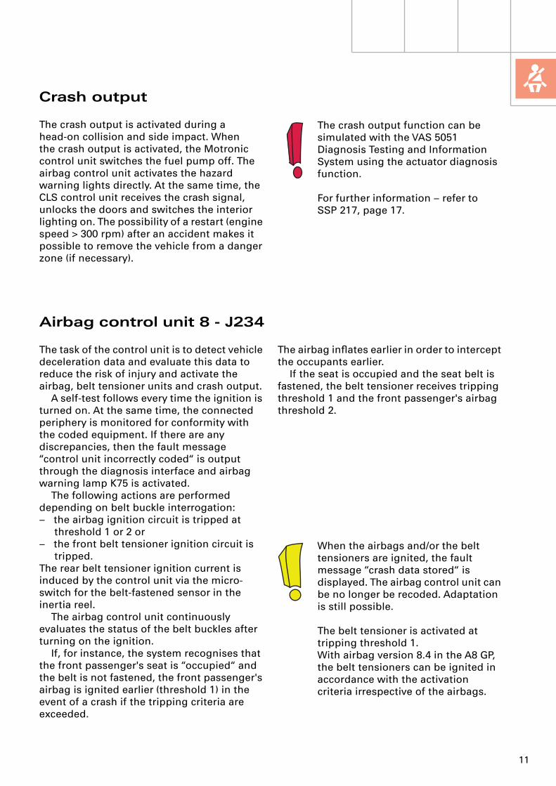
Crash output
The crash output is activated during a head-on collision and side impact. When the crash output is activated, the Motronic control unit switches the fuel pump off. The airbag control unit activates the hazard warning lights directly. At the same time, the CLS control unit receives the crash signal, unlocks the doors and switches the interior lighting on. The possibility of a restart (engine speed > 300 rpm) after an accident makes it possible to remove the vehicle from a danger zone (if necessary).
The crash output function can be simulated with the VAS 5051 Diagnosis Testing and Information System using the actuator diagnosis function.
For further information – refer to SSP 217, page 17.

12
Compared to the V8 4-valve engine, the new features and/or modifications are as follows:
Modifications
– to crankcase and crankshaft drive– to oil circuit– to cooling circuit
New features
– 5-valve cylinder head with roller type valve levers
– Camshaft adjuster – 3-stage intake manifold– Electro-hydraulic engine mount– Bosch ME 7.1 engine management system
V8 5V engines
Engine
SSP213_073
Introduction
AUDI has been producing state-of-the-art eight-cylinder engines since 1988. Engine displacement has increased from 3.6 litres to 4.2 litres.
The V8 engine together with Aluminium Space Frame technology was the technical basis for Audi's breakthrough into the luxury class of car manufacturing.
The V8 engines were fundamentally revised in the course of further development work.
The emphasis in this connection was on the following development goals:
– Meeting future exhaust emission regulations
– Reducing fuel consumption– Torque and performance gains– Enhancement of comfort/convenience– Reducing engine weight– Increased use of common parts of the
AUDI engine series.
You can find detailed information on the new V8 - 5V engine in SSP 217.

13
3.7 l 4.2 l
Engine codes AQG AQF (A8)ARS (A6)
Type V8 engine with 90
o
V-angle
Displacement 3697 cm
3
4172 cm
3
Power output 191 kW 260 bhp
at6000 rpm
228/220 kW 310/300 bhp
at 6000 rpm
Spec. power output
51.6 kW/l70.3 bhp/l
54.6 kW/l74.3 bhp/l
Torque 350 Nm at 3200 rpm
410 Nm at 3000 rpm
Spec. torque
94.7 Nm/l 98.3 Nm/l
Bore 84.5 mm 84.5 mm
Stroke 82.4 mm 93.0 mm
Compression ratio
11 : 1 11 : 1
Weight 198 kg 200 kg
Enginemanagement
Motronic ME 7.1
Fuel 98/95 RON
Firing order
1 - 5 - 4 - 8 - 6 - 3 - 7 - 2
Compliant with exhaust emis-sion standard
EU 3
Specifications
The specified performance data are only achievable using 98 RON fuel. A reduction in power output must be expected when using 95 RON fuel.
3.7 l V8 - 5 V
4.2 l V8 - 5 V
0
50
100
150
200
250
300
350
400
450
500
0
25
50
75
100
125
150
175
200
225
250
0 1000 2000 3000 4000 5000 6000 7000
0
50
100
150
200
250
300
350
400
0 1000 2000 3000 4000 5000 6000 70000
25
50
75
100
125
150
175
200
SSP217_004
SSP217_005
Torq
ue
(Nm
)
Engine speed (rpm)
Pow
er o
utp
ut
(kW
)
Torq
ue
(Nm
)
Engine speed (rpm)
Pow
er o
utp
ut
(kW
)

14
Engine
All the new features improve exhaust emission, fuel efficiency and torque while also increasing power output.
Power output of the 4.2 l has increased from 300 to 310 bhp.
The power output of the 3.7 l engine has increased to an even greater extent - namely from 230 to 260 bhp.
SSP217_020
The five-valve cylinder head with valve activation by a roller valve lever is employed in the new engine series.
Valve gear of this type produces a great deal less friction, particularly at low revs, thanks the use of optimised components.
5-valve technology

15
Gearbox
Automatic gearbox 01V
5-speed automatic gearbox 01V already offered a high level of driving comfort and handling dynamics even when it was launched in 1995. To be able to keep pace with growing demands in this area in future, the electro-hydraulic control of the 01V gearbox has been revised. The mechanicals (planet gear sets and clutches) have remained unchanged.
The new “generation“ of the 01V gearbox is used in the combination of petrol engines with the ME7 engine control unit and diesel engines which comply with the EU 3D exhaust emission standard.
Overview of new features
New gearbox input speed sender G182 for turbine speed data acquisition using a sensor system with Hall sender.
New valve body (hydraulic control unit) with modified operating cycles.
Gearbox control unit with higher processor power.
Facility for programming the control units of the vehicle and engine variant (currently not in use).
Additional ATF cooler for torquey engines.
SSP213_021
Valve body
Hall sensorG182

16
180-
180-
For design reasons, the speed of the planet carrier of the Ravigneaux planetary gear train has been used in the past to control shift operations.
The inductive sender G182 serves this purpose. The speed of the planet carrier was converted to a turbine speed in the gearbox control unit.
To achieve an excellent level of shift quality in all gears (precision control of shift operations), the precise turbine speed has to be detected (actual gearbox input speed).
Gearbox
Gearbox input speed sender G182
SSP213_096
Housing, clutch B
Gearboxinput shaft (turbine shaft)
Housing,clutch A
G182 (Hall sensor) previously:
G182(inductive sensor)
Planet carrier
C BA
E
D G
F
Final drive
Planetary gear train(Ravigneaux)
Measuring the turbine speed means gaining access to the housing of clutch A, which is responsible for power transmission.
The housing of clutch A is form-fitted to the turbine shaft and is located inside the housing of clutch B.
The distance between the sensor and the housing of clutch A makes it necessary to employ a system based on the Hall principle.
The system comprises the G182 and a magnetic ring, which is connected to the housing of clutch A.
The housing clutch B is made of non-magnetisable material, which means that the magnetic fields of the magnetic ring cannot be shielded from the sensor.

17
Electrical circuit
In comparison with the previously known Hall sensor systems, the G182 (Hall sensor) is now connected to control unit by two wires only.
The sensor signal and the earth supply is provided via Pin 44.
G182 is supplied with voltage via Pin 16.
SSP213_100
G182 J217
5
6
16
44
Plug-in connection to gearbox
Gearbox control unit interfaces
SSP213_020
Housing, clutch B
Magnetic ring
G182Gearboxinput speed sender
The advantages of precise turbine speed acquisition are as follows:
– Control and adaption during gearshifts to 1st gear and reverse. This reduces the engagement jolt when a drive gear is selected from P or N and when a rolling gearshift into 1st gear is executed.
Housing clutch A
– Improvement in shift quality in all gears through precise control and adaption of gearshifts.
– Improvement in self-diagnosis quality through early detection of a slipping clutch/brake.

18
Gearbox
Signal characteristic of G182
Test conditions:
Engine idling speedGate selector lever in position “P“
2 V/Div. 10 ms/Div.
0
T
Test conditions:
Ignition "on"orEngine at idling speedDrive position selectedBrake operated (turbine not running)
2 V/Div. 10 ms/Div.
0
T
Also refer to the relevant Workshop Manual
DOS connection
Red test probe Pin 44 SignalBlack test probe earth
DOS connection
Red test probe Pin 44 SignalBlack test probe earth
Auto mode
Auto mode
SSP213_098
SSP213_099
19
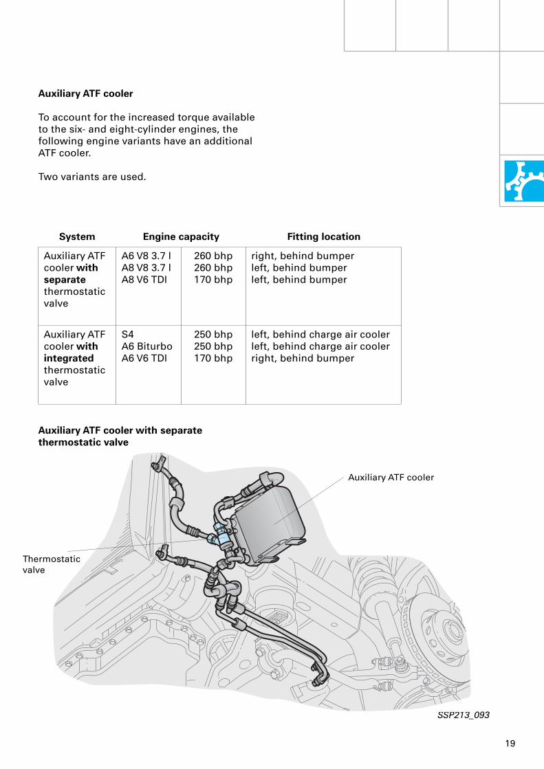
Auxiliary ATF cooler
To account for the increased torque available to the six- and eight-cylinder engines, the following engine variants have an additional ATF cooler.
Two variants are used.
System Engine capacity Fitting location
Auxiliary ATF cooler with separate thermostatic valve
A6 V8 3.7 lA8 V8 3.7 lA8 V6 TDI
260 bhp260 bhp170 bhp
right, behind bumperleft, behind bumperleft, behind bumper
Auxiliary ATF cooler with integrated thermostatic valve
S4A6 BiturboA6 V6 TDI
250 bhp250 bhp170 bhp
left, behind charge air coolerleft, behind charge air coolerright, behind bumper
Auxiliary ATF cooler with separate thermostatic valve
SSP213_093
Auxiliary ATF cooler
Thermostatic valve

20
Gearbox
The auxiliary ATF cooler is now connected in series with the main ATF cooler.
In this way the heat which develops as a result of the high power transmission is kept at an acceptable level.
The auxiliary ATF cooler is designed as an oil-air heat exchanger and connected downstream of the main ATF cooler (oil-coolant heat exchanger) via a thermostatic valve.
The thermostatic valve closes the return line to the gearbox at approx. 80oC and opens the supply line of the auxiliary ATF cooler.
ATF temperature < 80oC
SSP213_094
SSP213_095
ATF temperature > 80oC

21
Auxiliary ATF cooler with integrated thermostatic valve (example: Audi A6 Biturbo/S4)
When parts of the auxiliary cooler are replaced or ATF lines are disconnected, the auxiliary cooler goes to idling mode.
The auxiliary cooler cannot vent itself at low ATF temperatures, since the thermostatic valve does not open until the AFT temperature reaches approx. 80oC.
Given that the correct ATF level is tested at low ATF temperatures, non-compliance with the test requirements will result in a low ATF level.
Therefore, it is absolutely necessary to observe the instructions for carrying out the ATF check given in the Workshop Manual.
SSP213_092Thermostatic valve

22
Further aluminium components will be phased in for the four-link front suspension which will initially be used in the Audi A8 with effect from model year 1999.
New swing arms and wheel carriers made of aluminium will also be introduced.
Running gear
The reduction in weight offers additional benefits with regard to the running gear in particular, apart from general advantages with respect to fuel efficiency, exhaust emission and safety.
Driving comfort and handling dynamics have been substantially improved by reducing unsprung and rotating masses.
Axle
Front and rear swing arms
SSP213_091

23
The swing arms used in the Audi A8 are manufactured from an Al-Si-Mg alloy by means of a mould casting process. They are then subjected to heat treatment.
The swing arms for the Audi A6 - V8 and Audi S4 are forged from an AlMgSi alloy and then undergo heat treatment.
On account of the material pairing of aluminium and steel, it was necessary to reconstruct the wheel bearings and lower link anchorings.
To counteract the forces which are applied by the conical seats of the lower aluminium links, the taper seats in the swing arms are designed by means of press-fitted steel bushes.
SSP213_070
Support link
Taper seat made of steel
Swing arm
Clamping, lower link
SSP213_051
Forging, Audi A6 Casting, Audi A8

24
The aluminium swing arm and the weight optimised wheel hubs together achieve a weight benefit on the front axle of approx. 3.8 kg in the Audi A8 and approx. 2.5 kg in the Audi A6 - V8 and S4.
Wheel bearing
Running gear
SSP213_069
Threaded connection
Wheel bearing housing
Wheel hub
Threaded connection
Wheel bearing, threaded solution
The wheel bearings are not press-fitted into the swing arm or wheel bearing housing (previous construction). They are bolted directly to the swing arm in the form of a unit comprising the bearing and bearing housing.
This makes it possible to replace the wheel bearing without having to remove the swing arm or drive shaft.

25
The new central spring with leaf springs manufactured from stainless steel allows the brake pads to be changed without having to undo threaded connections or use special tools.
To avoid contact corrosion between aluminium and steel components, a new zinc-cobalt coating is applied to the floating caliper carrier and the outer floating caliper.
The following brake disc dimensions are used in the vehicles listed below:
The high-performance HP2 brake system, which has been in use since 1992, was optimised for– brake response– weight and– noise emission.
The new HP brake caliper is partly made of aluminium. This makes it possible to reduce weight by 2.2 kg at the front axle despite the fact that the brake discs are larger.
The guide pins of the floating caliper are positioned further outwards. Together with the large dimensioned centre pins, this provides a favourable leverage, resulting in little clearance between the housing frame and the brake carrier.
This measure, and an optimised brake pad location, act positively on brake response and noise emission. It also reduces brake wear.
HP2 brake caliper (Lukas)Central spring with leaf spring
SSP213_068
Brake disc Vehicle
323 x 30 mm A8 GP
A6 - V8
321 x 30 mm A6 Biturbo
S4

26
Running gear
4-piston brake caliper (Brembo)
The brake pad guides have stainless steel inlays.
SSP213_037
Weight saving and easy fitting are further advantages.
The brake discs measure 345 x 30 mm in keeping with engine performance.
An all-aluminium 4-piston brake caliper is used in the Audi S8.
The powder-coated brake caliper is attached to the swing arm radially. This fastening method has a positive effect on the brake caliper's vibration characteristics and helps reduce noise.
SSP213_071
Central spring
Stainless steel inlays
Radial screw connection at swing arm

27
Brake caliper, rear axle
As with the front wheel brake, the caliper is protected against corrosion by a zinc-cobalt coating.
The rear brake has aluminium floating calipers. A weight reduction of approx. 0.5 kg per brake caliper was achieved by using aluminium.
Brake disc: 269 x 22 mm for A8280 x 22 mm for S4
Piston diameter: 43 mm
SSP213_047
Since aluminium has a greater tendency to subside, the majority of the threaded connections are made using the torque angle tightening method.

28
Running gear
AA
SSP213_042
Oil filling
* unladen state… is the bump travel which occurswhen the “serviceable“ vehicle(with full fuel tank, spare wheel and tool kit)is standing on its wheels.
Two grooves in the damper tube serve as a bypass and reduce the resistance of the damper piston.
Approx. 40 mm in length, the grooves are located within the operating range of the damper piston when the vehicle is in an unladen* state or if it is laden with one to three persons.
When the spring travels short distances relative to the laden state (± 20 mm), the damper piston moves within the grooved area, reducing the damper forces.
This gives rise to good spring response, which in turn has a positive effect on driving comfort.
If the piston leaves the grooved area with the springs travelling large distances, the damper force increases. Firm damping in this drive position benefits driving safety and increases the vehicle's handling dynamics appreciably.
Gas-filled twin-sleeve shock absorber
In combination with a new suspension setup, shock absorbers, which have a damping characteristic dependent on engine load and travel, are used in the Audi A8 on the front and rear axles.
The gas-filled shock absorbers respond to vehicle vibration.
Bypassgrooves

29
The light-alloy hollow-spoke 8J x 18 rim, which will be used in an Audi for the first time in the Audi A8 with effect from model year 99, reduces wheel weight in comparison with the conventional cast aluminium wheel by approx. 2 kg per wheel.
The wheel comprises two parts. Designed as a hollow body, the wheel disc (with radial spokes) and rim base are joined by friction welding.
In addition to weight advantages, the two-piece construction makes it possible to easily combine the wheel spokes with rims of various widths.
Hollow-spoke wheel
SSP213_041
Reducing the weight of the wheels offers advantages in three respects:
– Reduces kerb weight (static)
– Reduces unsprung masses– Reduces rotating masses
The known benefits of reducing weight have a much more marked effect on rotating masses (e.g. wheels) than on “static masses“ (e.g. body), since these masses have to be made to rotate in addition to “normal acceleration“.
The aluminium hollow-spoke wheel, there-fore, helps to save a great deal of weight.
Friction weld
Wheel bolt hole
Radial spokes
Cavity
Rim width

30
Air conditioning system
Operating and display unit E87
– The information on ambient temperature supplied by sender G17 is now transferred directly to the dash panel insert, where it is evaluated and made available on the data bus.The information on ambient temperature supplied by sender G89 is still transferred directly to the operating and display unit, where it is evaluated and made available on the data bus.Operating and display unit E87 uses the lower ambient temperature value in each case.
– Air recirculation mode is automatically switched on for a defined period of time when the windscreen washer switch is operated.
– The control unit of E87 switches the windscreen heater on in defined conditions.
– Changed compressor switch-off conditions.
Technical status of operating and display unit – major product upgrade
Vehicles with a modified dash panel mid-section will be equipped with a new air conditioner operating and display unit with effect from model year A8 GP 1999.The automatic air conditioner control unit has been retained.
What features are new, both technically and visually?
– Operator keys have been repositioned.– Rear window heater button has been
integrated.– Seat heater control is replaceable. – Connection to CAN bus drive
(currently available on A8 only).– Key code
Windscreen heater button
Temperature sensorDash panel G56 with fresh air blower for temperature sensor G42
Seat heatercontrol
Rear window heater button
SSP213_011

31
The key is coded by reading out the fixed transponder code. The immobiliser control unit integrated in the dash panel insert supplies this information to operating and display unit E87 along the CAN bus.
Key code
When the ignition is turned on, operating and display unit E87 initially adopts the setting, temperature, air distribution and fresh air blower speed which were valid when the ignition was last turned off with this key.
J 220 J 218 J 217 J 104 E 87
– In the Audi A8, the operating and display unit is connected to the “Drive data bus“.
– Depending on the vehicle equipment specification, various control units belong to the drive data bus.
– If faults occur during information transfer within the bus system from the engine control unit or dash panel insert, then operating and display unit E87 does not switch the compressor on.
Using the current flow diagrams, you can establish what and how many control units are connected to the bus system.
SSP213_012
CAN LCAN HCAN screen
Up to 4 keys can be stored by E87.
Drive data bus in max. communication configuration:
J104 ABS control unit with EDLJ217 Automatic gearbox control unitJ218 Combination processor in dash panel
insertJ220 Motronic control unit
(or equivalent engine control unit)E87 Operating and display unit
Information exchange between the automatic air conditioning system and other systems now takes place along the CAN bus
To rule out any possibility of interference with the data transfer along the Drive data bus, the data wires are protected by an additional screen and are neutral externally.

32
Example: Information networking E87
Air conditioning system
4DO820043 M D2 Fully automatic air conditionerDXX →
Code 00001 WSCXXXXX
The combination processor in dash panel insert J218 supplies the following information:
– Coolant temperature “t“– Vehicle road speed “v“– Ambient temperature “ϑA“– Stationary period “th“
Engine control unit J220 supplies the following information:
– Engine speed “n“– Coolant temperature “t1“– Air conditioner compressor OFF/ON “K“– Intake air temperature “ϑL“– Air conditioner compressor Off “Ka“
The operating and display unit, therefore, is no longer connected directly to certain sensors.
Self-diagnosis
The operating and display unit is integrated in the self-diagnosis.The control unit ID appears on the display of the Diagnostic Testing and Information System (in this special case Index “M“).The drive data bus must also be tested (the air conditioner control unit utilises the information supplied by other control units).
Control unit ID
Index
J220J218
E87
t ht v Kat 1Aϑ LϑnCAN-BUS
K
SSP213_014
The operating and display unit sends the following messages to the air conditioning system along the Drive data bus:
– A/C ready (speed increase)– Driver input, auxiliary heater– Heated rear window– Heated windscreen– Compressor state OFF/ON– No heat output required– Ambient temperature (sensor)– Air conditioner pressure– Compressor load– Fresh air blower voltage
33
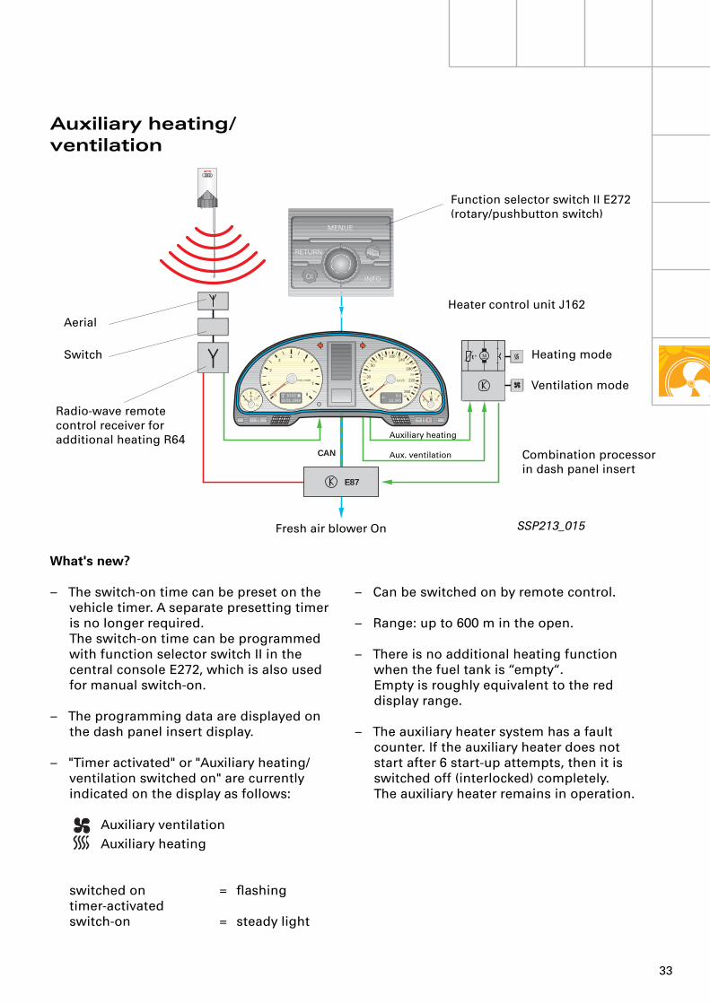
– Can be switched on by remote control.
– Range: up to 600 m in the open.
– There is no additional heating function when the fuel tank is “empty“.Empty is roughly equivalent to the red display range.
– The auxiliary heater system has a fault counter. If the auxiliary heater does not start after 6 start-up attempts, then it is switched off (interlocked) completely.The auxiliary heater remains in operation.
What's new?
– The switch-on time can be preset on the vehicle timer. A separate presetting timer is no longer required.The switch-on time can be programmed with function selector switch II in the central console E272, which is also used for manual switch-on.
– The programming data are displayed on the dash panel insert display.
– "Timer activated" or "Auxiliary heating/ventilation switched on" are currently indicated on the display as follows:
Auxiliary ventilationAuxiliary heating
switched on = flashingtimer-activatedswitch-on = steady light
E87
MENUE
INFO
RETURN
OI
to M
CAN
3
2
1
45
6
0
710
30
50
70 100140
180
220
260
20
40
60
80
160
200
240
120
1/21/1R0
0 890
°C
50 120280
- +
10:0218.01.1999
0.012.345
km
SSP213_015
Function selector switch II E272 (rotary/pushbutton switch)
Heater control unit J162
Combination processor in dash panel insert
Radio-wave remotecontrol receiver for additional heating R64
Fresh air blower On
Auxiliary heating/ventilation
Switch
Aerial
Heating mode
Ventilation mode
Auxiliary heating
Aux. ventilation

34
Temperature control
Automatically controlled air recirculation mode
Air conditioning system
In automatic air recirculation mode, a change-over from fresh air mode to air recirculation mode takes place automatically when the sensor detects noxious smells.
In automatic air recirculation mode, the change-over takes place as soon as the air quality sensor detects pollutants, i.e. before noxious smells actually develop.
Air quality sensor G238
Combi. filterFresh air intake
+
-
SO2
NOx
CO
C H6 6
C H6 14
H S2CS2
Digital square-wave signal to operating and display unit E87
Airborne pollutants
SSP213_079
The system components
– Air quality sensor G238An electronic component located in the fresh air intake upstream of the combina-tion filter.
– Combination filtersThe combination filters (there are 2 of them) replace the pollen filter. They comprise a particle filter containingactivated charcoal. They are fitted in the fresh air intake duct.
SSP213_081
Air quality sensor G238
SSP213_088
Combination filter

35
The operating principle of the automatic change-over system
Operating and display unit with automatically controlled air recirculation mode
SSP213_080
Manual function switch on/off button
The operating principle
A gas sensor detects pollutants in the ambient air.
When a high pollutant concentration is measured, a signal is transmitted to operating and display unit E87, which then switches from fresh air mode to air recirculation mode.
If the pollutant concentration drops below a given threshold, fresh air is again supplied to the vehicle interior.
The period between the detection of pollutants and the closing of the fresh air supply is bridged by the activated charcoal in the combination filter.
The operating and display unit decides whether to carry out a change-over automatically depending on the level of air pollution, the ambient temperature, driver input and whether the compressor is on or off.
What pollutants are detected?
The primary pollutants contained in the exhaust gases of the petrol engine are:CO - Carbon monoxideC6H14 - HexaneC6H6 - BenzeneC7H16 - n-heptane
The constituents of the exhaust gases of diesel engines are:NOX - Nitrogen oxidesSO2 - Sulphur dioxideH2S - Hydrogen sulphideCS2 - Carbon bisulphide
The “automatic air recirculation“ function can be switched on or off manually.
Ambienttemperature
Air pollution Air recirculation
> +2 oC Lowrise
yesmin. 25 sec.
> +2 oC Low no
+2 oC ... –5 oC
Higherrise
yes
< –5 oC Higherrise
max.12 sec.
ECON modecompressor off
max.12 sec.
Defrost mode no
Warm-up phase of sensorapprox. 30 sec.
no
Automatic air recirculation mode is limited to 12 minutes.
Example:

36
+
G238
E87
-
M M
The evaluation electronics in the sensor
The evaluation electronics integrated in the ultrasonic sensor module react to changes in sensor conductivity.
It achieves a high degree of sensitivity.
The system is “self-adaptive“, i.e. self-learning.
The electronics determine the average pollutant concentration in the ambient air and send a request for air recirculation to the air conditioner control unit by means of a square-wave signal.
The control unit now closes the air recirculation flap and fresh air flap depending on the ambient temperature, driver input, whether the compressor is on or off and the extent of air pollution at peak pollution levels.
This ensures that the system is not continuously switched to air recirculation mode in highly polluted areas.
Air flow flap positioning motor V71
Operating and display unit
Digital square-wave signal
Air quality sensor
SSP213_082
SSP213_081Air quality sensor G238
Air conditioning system
Air quality sensor G238
In principle, the sensor operates in much the same way as a lambda probe.
The measuring element is a mixed oxide sensor which incorporates semiconductor technology (tin oxide - SnO2). Sensitivity to noxious gases is increased by catalytic additives consisting of platinum and palladium.
The sensor has an operating temperature of approx. 350oC. Its power consumption of 0.5 watts is very low.
Service
– The air quality sensor is wear-free.– When washing the engine compartment, it
is important to ensure that the air quality sensor is not wetted with cleaning agent and solvent, as this will impair its ability to operate.
The sensor reacts to exhaust emissions of diesel engines about twenty times more sensitively than to petrol vapours.This is roughly equivalent to the sensitivity of the human nose.
Air recirculation flap positioning motor V113

37
The combination filter
The combination filter is a dust and pollen filter made of a non-woven fabric with an additional filter inlay of activated charcoal granulate.
– The non-woven fabric filters out dust and pollen.
– The non-woven fabric can also filter out gaseous pollutants such as ozone, benzene, nitrogen dioxide and other pollutants in the air flowing through the filter.
Function
To absorb the gaseous impurities in the air flowing through the filter until the fresh air flap is closed and the air conditioning system has gone into air recirculation mode.
Air then no longer flows through the filter. Air recirculation mode inevitably extends the filter's service life.
The activated charcoal layer reacts differently to different pollutants:
– Certain pollutants are bound permanently in the filter.
– Others are converted to harmless compounds in much the same way as in a catalytic converter.
– The activated charcoal has the same effect on the remaining pollutants as a condenser.At increasing pollution levels, pollutants are absorbed to saturation point.When the pollutant concentration decreases, the absorbed particles are partially released.
Some of the pollutants are bound permanently in the filter.It is necessary, therefore, to change the filter from time to time.
Service
The combination filter must be replaced at the prescribed service intervals.
Since the activated charcoal layer permanently binds a fraction of the pollutant particles, it is advisable to replace the filter earlier in certain conditions of use:
– when operating the vehicle in areas where air pollution levels are high,
– when operating the vehicle with the “automatic air recirculation“ function switched off most of the time.
The combination filter can also be fitted in vehicles without an automatically controlled air recirculation mode.
SSP213_088
Activated charcoal granulate
Non-woven fabric

38
Air conditioning system
Function diagram
The function diagram represents a simplified current flow diagram and shows how all component parts of the air conditioning system interact with one another.
Components
D Ignition switch, terminal 15E87 Air conditioner operating and display
unitF129 Air conditioner pressure switchF183 Vent switch, middle leftF184 Vent switch, middle rightG89 Fresh air intake duct, temperature sensor G92 Temperature flap positioning motor
potentiometerG107 Sunlight penetration photo sensorG111 Air conditioner compressor speed senderG113 Air flow flap positioning motor
potentiometerG135 Defrost flap positioning motor
potentiometerG136 Potentiometer in left-hand central vent
positioning motorG137 Potentiometer in right-hand central vent
positioning motorG138 Potentiometer in central vent positioning
motorG139 Potentiometer in left-hand footwell flap
positioning motorG140 Potentiometer in right-hand footwell flap
positioning motorG141 Potentiometer in rear footwell vent
positioning motorG142 Potentiometer in central ventG143 Potentiometer in air recirculation flap
positioning motorG150 Vent temperature sender, leftG151 Vent temperature sender, rightG238 Air quality sensorJ44 Magnetic clutch relayJ126 Fresh air blower control unitJ218 Combination processor in dash panel
insertN25 Air conditioner magnetic clutchN175 Heat regulation valve leftN176 Heat regulation valve rightS Fuse
V2 Fresh air blowerV50 Coolant circulation pumpV68 Temperature flap positioning motorV71 Air flow flap positioning motorV102 Centre vents positioning motorV107 Defrost flap positioning motorV108 Left footwell flap positioning motorV109 Right footwell flap positioning motorV110 Centre left vent positioning motorV111 Centre right vent positioning motor V112 Rear footwell vent positioning motorV113 Air recirculation flap positioning motorZ1 Heated rear window
Auxiliary signals and connections
1 From dash panel insert lightinginstruments (terminal 58s)
2 From steering column switch/washercontact
3 To relay for fan speed 1
4 Air conditioner compressor On/Off signal
5 Speed increase signal
6 Windscreen heater
7 To relay for fan speed 2 (optional)
8 From relay for solar roof
9 From auxiliary heating control unit
10 From steering column switch terminal 58
11 To relay for radiator fan speed 2J101
12 CAN data bus
31 Central earth
X Signal earth
Code codes
= Input signal
= Output signal
= Positive
= Earth

31
X
15
30
2 4 6 8
M
V108
G139
S
31
t° t°
E87
CA
N -
BU
S L
1
3 5 7 9
t°
CA
N -
BU
S H
J218
G107
1
F183 F184
S
M
V50 N175 N176
S S
J44 N25
S
M
V2
G238 J126
S
X
G150 G151 G89
G142
M
V107
G135
M
V102
G138
M
V71
G113
M
V68
G92
31
Z1
D+15
31
10
S
31
X
15
30
31
M
V109
G140
F129
31
11
X
M
V113
G143
M
V112
G141
M
V111
G137
M
V110
G136
in out
X
12
SSP213_017
39

40
Electrics
Radio-controlled clockThe time of day and date are displayed on the two-line clock display. The following segments are also integrated in the clock display:
– Radio tower at left of clock; the radio tower symbol is only displayed when a radio signal is received.
– Additional heating and auxiliary ventilation are indicated by symbols, with separate illumination when ignition is off.
You can find further information regarding distance and cruise control as well as tyre pressure monitoring in a special SSP.
Dash panel insert
The basic information which is displayed by the dash panel insert has been adopted unchanged.
The new eight-colour dot matrix display is located in the middle.
The messages issued by the driver information system (DIS) cover the representation of– graphic information of additional external
systems, e.g. navigation, radio, telephone– Ambient temperature– On-board computer– Shift indicator– Auto-Check System (in the background)
A new feature is:– Distance and cruise control display– Tyre pressure monitoring
(equipment-dependent)– Menu guidance
SSP213_061
SSP213_062
ANTENNEFM1 - 6 TP
P R N 4 3 2
6
730
5040
20
D
+25.5 °C
L
100km0 5.2
12:5512.8.1998

41
Options– Computer– Clock– Tyre pressure*– Auxiliary heating*– Auxiliary ventilation*– Radio display– Speed warning
HelpThe Help function helps you to make the right choices when making entries.
For instructions on how to operate the various menus as well as the functions, please refer to the vehicle's Owner's Manual.
SSP213_063
SSP213_065
MENUE
RETURN
INFO
6
730
5040
20
Menu guidance
In conjunction with the major product upgrade of the Audi A8, menu guidance has been introduced for the dash panel insert.The settings are made using function selector switch II E272 in the central console. Options menus are represented on the display of the driver information system.
The start menu has the following display modes:– Menu from– Interrogate– Options– Help
The following functions are assigned to the start menu display modes:
Menu from– On-board computer– Auto-Check Control/radio or telephone
data– Ambient temperature– Speed warning– "Door open/boot lid open" warning– Information display or selector lever
position display for automatic gearbox– Navigation display*
Interrogation functions– Oil level– Inspection
* equipment-dependent
Display type
Menu fromInterrogateOptions
Help

42
Electrics
SSP213_097
Before doing this, it is very important to interrogate the fault memory and note down the values for Service Interval Display and mileage counter (refer to the relevant Workshop Manual).
3
2
1
45
6
0
710
30
50
70 100140
180
220
260
20
40
60
80
160
200
240
120
1/21/1R0
0 890
°C
50 120280
- +
10:0218.01.1999
0.012.345
km
SSP213_059
In the A8 GP, all warning lamps have an LED, i.e. when a warning lamp fails, the dash panel insert has to be replaced.
Multi-way connector, 32-pin, green
Multi-way connector, 32-pin, blue
Multi-way connector, 32-pin, grey
Multi-way connector, 4-pin, black
Internal phototransistor
Dimmer button
Lighting
The brightness of the dash panel insert is regulated depending on
– an integral phototransistor– an external phototransistor (G107 in E87)– the adjustment made using the dimmer
buttons
In addition to the combination lighting, the driving light indicator lamps (high beam, parking light, fog lights, etc.) are also dimmed depending on ambient luminosity.
Connections at dash panel insert
There are four multi-way connectors on the microprocessor-controlled dash panel insert.
43
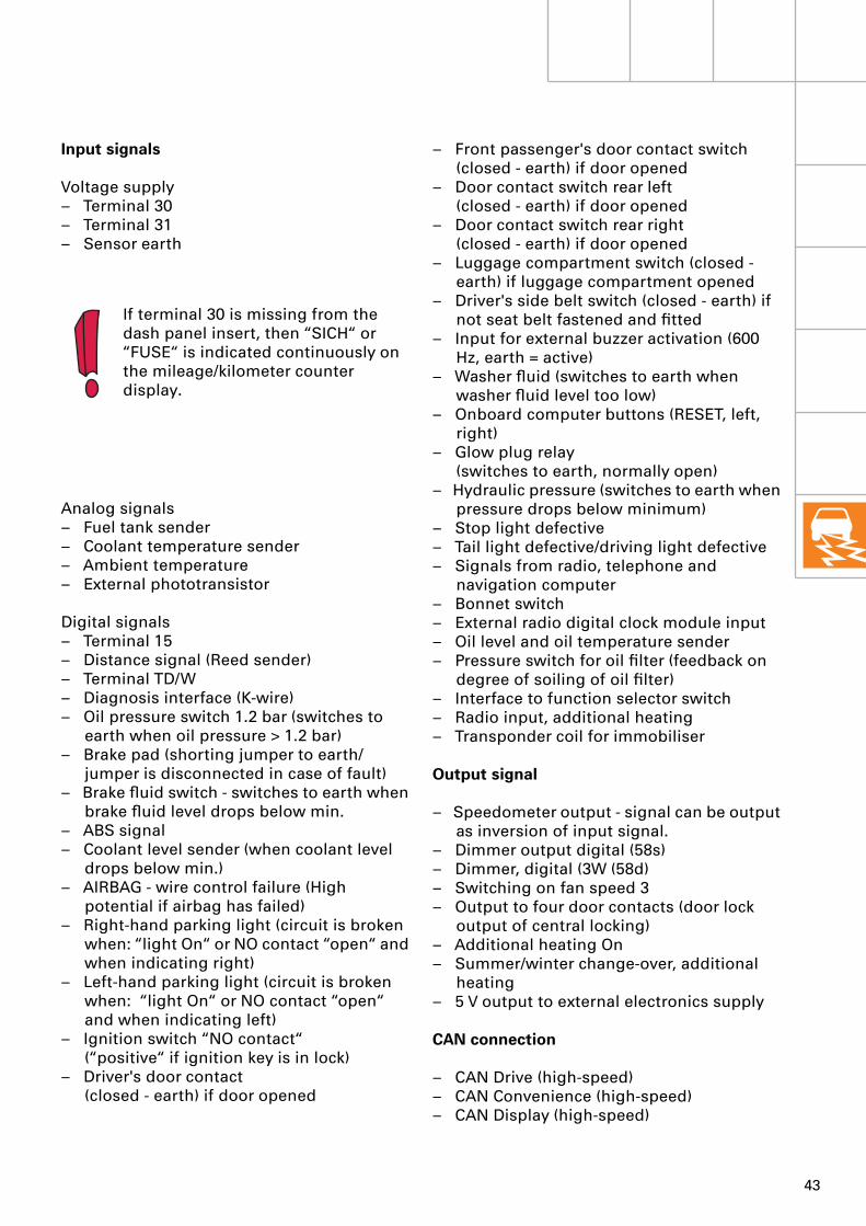
– Front passenger's door contact switch(closed - earth) if door opened
– Door contact switch rear left (closed - earth) if door opened
– Door contact switch rear right (closed - earth) if door opened
– Luggage compartment switch (closed - earth) if luggage compartment opened
– Driver's side belt switch (closed - earth) if not seat belt fastened and fitted
– Input for external buzzer activation (600 Hz, earth = active)
– Washer fluid (switches to earth when washer fluid level too low)
– Onboard computer buttons (RESET, left, right)
– Glow plug relay (switches to earth, normally open)
– Hydraulic pressure (switches to earth when pressure drops below minimum)
– Stop light defective– Tail light defective/driving light defective– Signals from radio, telephone and
navigation computer– Bonnet switch– External radio digital clock module input– Oil level and oil temperature sender– Pressure switch for oil filter (feedback on
degree of soiling of oil filter)– Interface to function selector switch – Radio input, additional heating– Transponder coil for immobiliser
Output signal
– Speedometer output - signal can be output as inversion of input signal.
– Dimmer output digital (58s)– Dimmer, digital (3W (58d)– Switching on fan speed 3– Output to four door contacts (door lock
output of central locking)– Additional heating On– Summer/winter change-over, additional
heating– 5 V output to external electronics supply
CAN connection
– CAN Drive (high-speed)– CAN Convenience (high-speed)– CAN Display (high-speed)
Input signals
Voltage supply– Terminal 30– Terminal 31– Sensor earth
Analog signals– Fuel tank sender– Coolant temperature sender– Ambient temperature– External phototransistor
Digital signals– Terminal 15– Distance signal (Reed sender)– Terminal TD/W– Diagnosis interface (K-wire)– Oil pressure switch 1.2 bar (switches to
earth when oil pressure > 1.2 bar)– Brake pad (shorting jumper to earth/
jumper is disconnected in case of fault)– Brake fluid switch - switches to earth when
brake fluid level drops below min.– ABS signal– Coolant level sender (when coolant level
drops below min.)– AIRBAG - wire control failure (High
potential if airbag has failed)– Right-hand parking light (circuit is broken
when: “light On“ or NO contact “open“ and when indicating right)
– Left-hand parking light (circuit is broken when: “light On“ or NO contact “open“ and when indicating left)
– Ignition switch “NO contact“ (“positive“ if ignition key is in lock)
– Driver's door contact(closed - earth) if door opened
If terminal 30 is missing from the dash panel insert, then “SICH“ or “FUSE“ is indicated continuously on the mileage/kilometer counter display.

44
The dash panel insert can maintain communi-cations on the CAN bus up to an operating voltage of 6.5 V.
Bus systems
The dash panel insert is equipped with three CAN buses and a gateway function.
The following bus systems are used:
– CAN DriveHigh-Speed CAN at a transfer speed of 500 kBaud
– CAN ConvenienceHigh-Speed CAN at a transfer speed of 100 kBaud
– CAN-DisplayHigh-Speed CAN at a transfer speed of 100 kBaud
A 'gateway' is a function which assembles pieces of information from various identifiers (data messages) of a CAN bus to generate an identifier of another CAN bus, thus creating a new message.
Electrics
You can find further information regarding the CANbus in SSP 186.
SSP213_052
1 2 3 4 5 6
7 8 9 10 11 12 13
1 2 3 4 5 6
3
2
1
45
6
0
710
30
50
70 100140
180
220
260
20
40
60
80
160
200
240
120
1/21/1R0
0 890
°C
50 120280
- +
10:0218.01.1999
0.012.345
km
MFL Interface J453Relay slot 3+4
Data message
Navigation operating electronics control unit J402
Combination processor indash panel insert J218

45
CAN Drive
Ambient temperature display:
The combination processor in the dash panel insert evaluates the analog voltage signal provided by the NTC resistor for digital display in the dash panel insert. The digital signal is encoded as a binary number and included in the data message. This signal is directly available to all connected control units.
The air conditioner operating and display unit outputs the ambient temperature indicated by the plenum chamber sensor G89 via the CAN Drive output.
The dash panel insert compares the two temperature values and displays the lower of the two values.
The following control units are networked to one another in CAN Drive:
– Motronic control unit J220
– Automatic gearbox control unit J217
– ABS control unit with EDL J104
– Air conditioner operating and display unit E87
– Combination processor in dash panel insert J218
The networking of the control units, i.e. mutual editing and dispatch of measured data, can be demonstrated well by means of the following examples:
J220
J217E87
J218
J104 SSP213_039
46
Electrics
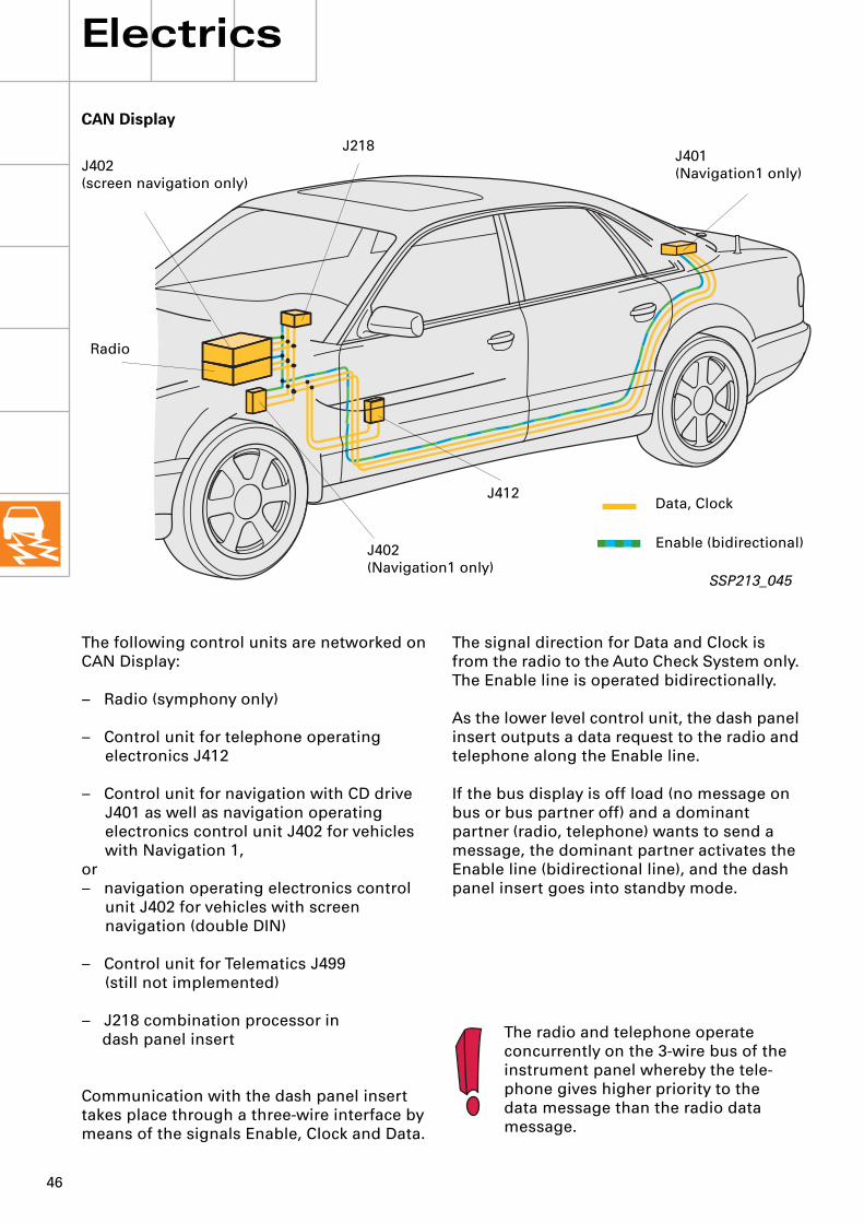
CAN Display
The signal direction for Data and Clock is from the radio to the Auto Check System only. The Enable line is operated bidirectionally.
As the lower level control unit, the dash panel insert outputs a data request to the radio and telephone along the Enable line.
If the bus display is off load (no message on bus or bus partner off) and a dominant partner (radio, telephone) wants to send a message, the dominant partner activates the Enable line (bidirectional line), and the dash panel insert goes into standby mode.
The following control units are networked on CAN Display:
– Radio (symphony only)
– Control unit for telephone operating electronics J412
– Control unit for navigation with CD drive J401 as well as navigation operating electronics control unit J402 for vehicles with Navigation 1,
or– navigation operating electronics control
unit J402 for vehicles with screen navigation (double DIN)
– Control unit for Telematics J499(still not implemented)
– J218 combination processor indash panel insert
Communication with the dash panel insert takes place through a three-wire interface by means of the signals Enable, Clock and Data.
SSP213_045
Radio
J412
J401(Navigation1 only)J402
(screen navigation only)
The radio and telephone operate concurrently on the 3-wire bus of the instrument panel whereby the tele-phone gives higher priority to the data message than the radio data message.
J218
J402(Navigation1 only)
Enable (bidirectional)
Data, Clock

47
The flag byte, dataset and check byte are transmitted along the Data and Clock wires.
The data message comprises a total of 18 bytes which are transferred from the radio or telephone to the dash panel insert and displayed as a message.
1 The first byte with differentbits contains the identifier for radio or telephone.
2 - 17 bytes contain the dataset ormessage
18 byte is the check byte which containsthe checksum of the message.
SSP213_046
Flag byte Check byteDataset
Enable
Data
Clock
SSP213_089
No data messages are transferred along the Enable line.

48
Electrics
The following information is transferred:
– Messages from the dash panel insert to the navigation system through Enable pulse length coding (request new screen, navigation no longer on display, repeat request, radio request, etc.)
– Navigation messages for screen build-up, radio, telephone messages and other control messages from the navigation system to the dash panel insert. Data are contained in protected data structures.
– Data messages from the navigation system to the components radio and telephone.
– Data messages from the components radio and telephone to the navigation system.
The navigation interfaceInterfaces the dash panel insert to the parallel components radio/telephone (MFL Interface). Both interfaces are implemented as a wire bus (Clock, Data, Enable). However, message buildup, protocols and transfer rates of bus subscribers radio/telephone and navigation system are different. The navigation interface fulfills the tasks of implementing and adap-ting information transfer in both directions.
SSP213_090
RT
+
-
J412 J453
J402
3
2
1
45
6
0
710
30
50
70 100140
180
220
260
20
40
60
80
160
200
240
120
1/21/1R0
0 890
°C
50 120280
- +
10:0218.01.1999
0.012.345
km
TRACKSEEK
CD CDC
AM
FM
1DOLBY SYSTEM
2
1 2
TAPEPLAY SDE
BASS MIDDLE TREBLE BALANCE FADER
1 2 3 4 5 6
EJECT Audi symphony
AS
TP
RDS
RANDOM
FR FF
TUNE SCAN
EJECT
J218
MENUE
RETURN
INFO
1-wire CAN
Tel. bus
Tel. (MFL) Multi-functionsteering wheel interface
Symphony radio
NavigationFunction selector switch
3-wire high-speed CAN
Remote
3-wire low-speed CAN
Enable (bidirectional) Data, clock
Navigation(example: Navigation1)

49
CAN Convenience
In CAN Convenience, the following control units are internetworked:
– Combination processor in dash panel insert J218
– Control unit for tyre pressure monitoring J502
– Control unit for parking aid J446
– Additional heating control unit J364
SSP213_040
J218
J502
J364
J446

50
Electrics
Self-diagnosis of dash panel insert
New contents in the followingfunctions:
02 - Interrogate fault memory08 - Read measured value block10 - Adaptation
Interrogate fault memory
With the introduction of CAN systems, the interrogation/fault numbers which are monitored and stored have been incremented.
In the fault memory of the Audi A8, for example, this results in the following additional fault locations which can be displayed:
Data line from Navigation - implausible signalNavigation operating electronics control unit - no communicationControl unit for Telematics - no communicationTelephone - no communicationRadio control unit - no communicationEngine control unit - no communicationGearbox control unit - no communicationABS control unit - no communicationTyre pressure monitoring - no communicationParking aid - no communicationCAN Display - defective
in single-wire modeCAN Convenience - defective
in single-wire modeCAN Drive - defective
in single-wire modeAmbient temperature signal - open circuit/
short circuit to positive/short circuit to earth
Please use the current Workshop Manuals to rectify any faults.
A static fault is saved if the malfunction exists for at least 20 seconds.
SSP213_038

51
If a field in the display group contains no entries, then this is an indication that this control unit is not connected to the CAN bus.
08 - Read measured value block
Display groups 12 to 16 give information on the Flexible Service Interval display:
Display groups 125, 126, 130 and 140 clearly show what control units are located on the CAN bus.
Measured value block 125
Read measured value block 125 →Engine 1 Gearbox 1
Display
ADR - display field for CAN interface– 1 - denotes ADR control unit is one of the CAN bus
users– Empty display field denotes ADR control unit is not
connected to CAN bus
ABS - display field for CAN interface– 1 - denotes ABS control unit is connected to
CAN bus– Empty display field denotes ABS control unit is not connected
to CAN bus
Gearbox - display field for CAN interface– 1 - denotes gearbox control unit is connected to CAN bus– Empty display field denotes gearbox control unit is not connected to CAN
bus
Engine - display field for CAN interface– 1 - denotes engine control unit is connected to CAN bus– Empty display field denotes engine control unit is not connected to CAN bus
Measured value block 126
Read measured value block 126 →Air conditioner 1
Display
Air conditioner - display field for CAN interface– 1 - denotes air conditioner control unit is connected to CAN bus– Empty display field denotes air conditioner control unit is not connected to CAN bus

52
Electrics
Measured value block 130
Read measured value block 130 → Display
Parking aid - display field for CAN interface– 1 - denotes parking aid control unit is connected to
CAN bus– Empty display field denotes parking aid control unit
is not connected to CAN bus
Additional heating - display field for CAN interface– 1 - denotes additional heating control unit is connected to CAN bus– Empty display field denotes additional heating control unit is not
connected to CAN bus
Tyre pressure - display field for CAN interface– 1 - denotes tyre pressure control unit is connected to CAN bus– Display field denotes tyre pressure control unit is not connected to CAN bus
Measured value block 140
Read measured value block 140 → Display
Telematics - display field for CAN interface– 1 - denotes Telematics control unit is connected to
CAN bus– Empty display field denotes Telematics control unit
is not connected to CAN bus
Navigation - display field for CAN interface– 1 - denotes navigation control unit is connected to CAN bus– Empty display field denotes navigation control unit is not
connected to CAN bus
Telephone - display field for CAN interface– 1 - denotes telephone control unit is connected to CAN bus– Empty display field denotes telephone control unit is not connected to CAN
bus
Radio - display field for CAN interface– 1 - denotes radio control unit is connected to CAN bus– Display field denotes radio control unit is not connected to CAN bus

53
10 - Adaptation
In the Audi A8 GP, for example,the following additional adaptation functions can be influenced:
Channel02 - Adaptation of FSIA to Fix or Flexible18 - Operating states of the additional
heating40 - Mileage/kilometres since inspection41 - Time since inspection42 - Minimum mileage/kilometres to
inspection43 - Maximum mileage/kilometres to
inspection44 - Maximum time interval to
inspection45 - Oil grade for calculating the
maintenance interval47 - Soot entrainment for calculating the
maintenance interval for diesel vehicles
The fitted control units which are connected to the CAN Drive in the Audi A8 GP are added.
Example: Automatic gearbox
Engine + gearbox + ABS + dash panel insert =1 + 2 + 4 + 1024 = 1031
Table: Drive CAN
Equipment Adaptation value
Engine 1
Gearbox 2
ABS 4
Air conditioner 8
ADR 32
Dash panel insert 1024
48 - Thermal load of oil forcalculating the maintenance interval fordiesel vehicles
60 - Adaptation, CAN Drive
61 - Adaptation, CAN Convenience
62 - Adaptation, CAN Display
The adaptation values can be found in the relevant Workshop Manual.

54
Electrics
Sound system
symphony radio
FM range:
The FM reception signals are consecutively supplied to the radio by 4 amplifiers, FM/AM and FM via the change-over box.
The radio makes a frequency adjustment and requests the change-over box via the intermediate frequency line to utilise the appropriate aerial and the highest reception signal.
AM range:
The reception signal in the AM range is permanently supplied via the FM/AM amplifier.
The symphony radio has the following outstanding features:
– Integrated Single-CD Player– Improved ease of operation, e.g. separate
sound control in the high, mid and low frequency bands
– System is CAN bus compatible– Use of the change-over box
The geometry of the rear window results in different magnetic field strengths which can impair the reception (Rx) level in certain situations.
To optimise reception, aerials for the FM range as well as an aerial for the AM range are integrated in the rear window in the Audi A8 4.
TRACKSEEK
CD CDC
AM
FM
1DOLBY SYSTEM
2
1 2
TAPEPLAY SDE
BASS MIDDLE TREBLE BALANCE FADER
1 2 3 4 5 6
EJECT Audi symphony
AS
TP
RDS
RANDOM
FR FF
TUNE SCAN
EJECT
SSP213_085
SSP213_086
Change-overbox
symph. radio
CD changer
FM1/AM
FM2
FM2 FM3
AM
FM1 FM4
optional
Aerial signal
Intermediate frequency line
FM3
FM4

55
Flexible Service Interval Display
The Service Interval Display informs the driver when a service is necessary.
The Fixed Interval Display, i.e. with limitation of distance or time to next service to 15,000 km or 1 year respectively, will be replaced gradually by a Flexible Service Interval Display.
Compared to rigid maintenance intervals, the Flexible Service Interval Display allows better use to be made of the engine oil's perfor-mance reserves. A new sensor for detecting oil level and oil temperature has been developed for this purpose.
Warning display1. Priority oil level “min“2. Priority oil level “min“ over
distance
You can find further information on the Flexible Service Interval Display in SSP 207.
6
730
5040
20
6
730
5040
20
MENUE
RETURN
INFO
6
730
5040
20
6
730
5040
20
The oil level and the mileage/kilometres to next service can be interrogated using of the function selector switch.
SSP213_067
Oil level sensor
Bonnet contact
Engine con-trol unit
Mileage/kilo-meter counter
Dash panel insert
How do you identify what variant (Fixed or Flexible) is fitted?The adaptation channels, e.g. 45, 46 and 47, can only be displayed in connection with the FSIA!
Oil levelhigh
Oil level
Back
Inspection
Inspectionin
8000 km
Back
Interrogate
Oil levelInspection
BackDisplayMenu fromInterrogateOptions
Help

56
Electronic tyre pressure monitoring
MENUE
RETURN
INFO
Electrics
The control unit evaluates the tyre pressures or changes in tyre pressure and relays the appropriate warnings to the dash panel insert where they are displayed to the driver by the Driver Information System (DIS).
The following situations can be identified:
– Gradual loss of pressure; the driver is informed early, allowing tyre pressure to be corrected.
– Sudden loss of pressure; the driver is warned immediately during the trip.
– Excessive loss of pressure when vehicle is stationary; the driver is warned straight after turning on the ignition.
Function
The electronic tyre pressure monitor continuously monitors tyre pressure during the trip and when the vehicle is stationary.
An electronic metering and transmitter unit integrated in the tyre valve transmits a radio signal to a receiver aerial fitted in the wheel housing and control unit for monitoring the tyre pressure at regular intervals.
SSP213_001
Tyre valve with wheel electronics
Receiver aerials
Control unit for tyre pressure monitoring
Function selector switch
Combination processor in dash panel insert

57
MENUE
RETURN
INFO
The wheel electronics
together with the valve form a compact unit which is bolted to the rim.
An intelligent sensor developed specially for this application is located here.
This sensor comprises a pressure sensor, a temperature sensor and an integrated circuit for complete measured-value acquisition and signal conditioning.
This sensor activates the HF transmitter stage. The sensor and transmitter stage are powered by a lithium battery.
The receiver aerial
receives the data message supplied by thewheel sensor and transfers this to the control unit for tyre pressure monitoring for further processing.
The function selector switch
The electronic tyre pressure monitoring function is activated and the momentary tyre pressures is stored in the submenu for tyre pressure using the selector switch function.
SSP213_005
SSP213_004
SSP213_063
The subject of electronic tyre pres-sure monitoring is dealt with in detail in one of the following SSPs.

58
Electrics
Acoustic parking aid, front and rear
SSP213_050
Intermittent warning beeps sound when the vehicles comes within approx. 160 cen-timetres of an obstacle. The closer the vehicle moves towards the obstacle, the shorter the interval between warning beeps.
When the vehicle comes within approx. 20 cm of an obstacle, the intermittent beeps become a continuous tone. To the driver, the direction of the warning beeps is identical to the direction of the obstacle.
The Acoustic Parking System (APS) is an ultra-sound based system that helps the driver to manoeuvre the vehicle. It alerts the driver by means of audible signals when the vehicle is approaching an obstacle.
Function
After turning on the ignition, the micro-computer performs a self-test and checks the periphery. The control unit is now permanently in operation.
Distance sensing is activated when you select a drive position or a gear. The function display in the parking aid switch lights up to indicate that the parking aid, and with it the distance sensing function, is active.
Intermittent warning beeps
Cont. tone
Cont. toneIntermittent warning beeps

59
Ultrasound converter
The ultrasound converters are housed in the front and rear bumper covers. They act as actuators and sensors, i.e. they transmit and receive signals.
Control unit for parking aid J446 gives the command to transmit or receive ultrasonic waves.
The converters receive an echo reflected by the obstacle. In the converters, evaluation electronics calculate the distance between the vehicle and an obstacle from the echo propagation time, i.e. the time between transmission and reception of the signal to the individual converters.
The evaluation electronics in the converters generate digital signals from the echo signals and relay them to the control unit.
If the distance between the two outer sensors and the obstacle does not change, the vehicle is driving alongside a wall.
The warning beep is switched off after approx. 3 seconds and does not sound again until the distance to the obstacle lessens.
In the control unit, the time between the command to transmit ultrasonic waves and receive digital signals from the converter is evaluated by timers.
The distance between the vehicle and the obstacle is calculated from the different times computed by the control unit using the triangulation method.
Triangulation
From the various distances it can be concluded that the object is located between the 2nd and 3rd converters. Height h can be determined using Pythagoras’ theorem. The resulting distance is 44 cm.
Trailer operation is detected via the microswitch in trailer socket F216 and deactivates the rear APS.
SSP213_083
SSP213_072
99 cm
59 cm
45 cm 75 cm
h = ?
Converters
Sample calculation

60
Electrics
Function diagram
F4 Reversing light switchF123 Anti-theft alarm, tailgate/boot lid
contact switchF125 Function selector switch/automaticF216 Rear fog light cut-out, contact switchE266 Contact switch for parking aidK136 Parking aid warning lampK159 Parking aid warning lampJ218 Combination processor in dash panel
insertJ446 Control unit for parking aid
G202 Parking aid sender, rear leftG203 Parking aid sender, rear left
centreG204 Parking aid sender, rear right
centreG205 Parking aid sender, rear rightG252 Parking aid sender, front rightG253 Parking aid sender, front right
centreG254 Parking aid sender, front left
centreG255 Parking aid sender, front leftH15 Warning buzzer for rear parking aidH22 Warning buzzer for front parking aid
The function display in the parking aid switch is lit continuously when the parking aid is active. If a fault occurs in a converter or tone generator, the function display flashes at a frequency of 2 Hz.

X
1530
X
1530
31
S
31
J446
v
F123K136/K159E266
G255 H15 H12G254G253G252G206G205G204G203
F4
AS
30+
15+
D
J218
F125
SSP213_019
61

62
+12V-12V
DC/DC
Electrical circuit
Electrics
Windscreen heater
Function
The windscreen is not heated like the rear window, i.e. by means of individual wires. It is heated by a metal foil sandwiched between the windows.
Windscreen – schematic diagram of layered structure
Outer glass paneThickness 2.1 mm
Decorative printGrid area
Heated IRR coatingResistance 2.2 Ω
PVB foil 0.38 mm thick
PVB foil 0.76 mm thick
Inner glass paneThickness 1.6 mm
Decorative printFully printed area
Uncoatedborder region
SSP213_006
SSP213_003
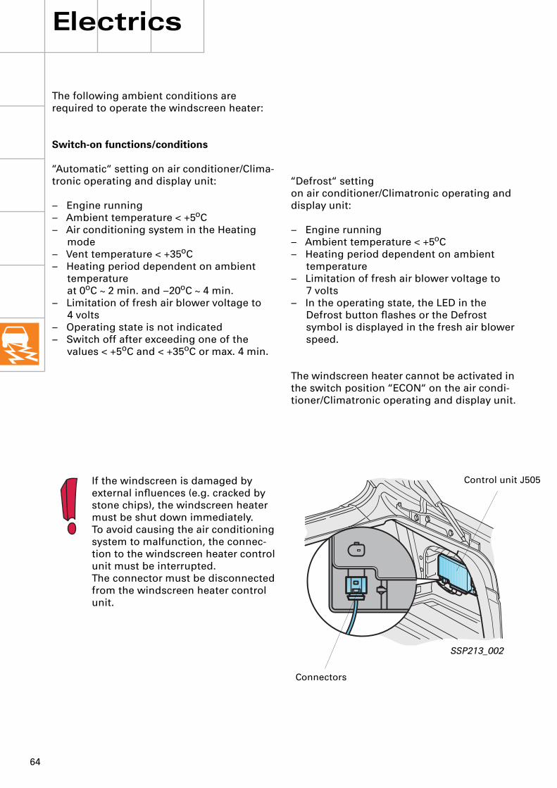
Control unit for heated windscreen J505
Air cond./Clima-tronic operating and display unit E87
Communication between the air conditioner/Climatronic operating and display unit E87 and the control unit for heated windscreen J505 is bidirectional.
Air conditioner/Climatronic operating and display unit E87 issues a heating request to control unit J505.
The control unit for heated windscreen J505 sends the confirmation for operation of the windscreen heater to the air conditioner/Climatronic operating and display unit along the same wire.
Windscreen
Bidirectional

63
Signal shape of heating request issued by air conditioner/Climatronic operating and display unit E87
The air conditioner/Climatronic operating and display unit sends a Low signal to the control unit for heated windscreen J505 as a heating request.
Signal shape of windscreen ready for heating as well as heating by the control unit for heated windscreen J505
The control unit for heated windscreen J505 signals when the windscreen heating is ready in the form of a Vbat signal.
Windscreen heating On is implementedby a 1/2 Vbat signal.
t
t
Control unit for heatedwindscreen J505Air conditioner/Cli-
matronic operating and display unit E87
Control unit for heated windscreen J505Air conditioner/Cli-
matronic operating and display unit E87
Bidirectional
Bidirectional
Vbat
1/2 Vbat
Vbat
1/2 Vbat
64
Electrics
“Defrost“ settingon air conditioner/Climatronic operating and display unit:
– Engine running– Ambient temperature < +5oC– Heating period dependent on ambient
temperature– Limitation of fresh air blower voltage to
7 volts– In the operating state, the LED in the
Defrost button flashes or the Defrost symbol is displayed in the fresh air blower speed.
The windscreen heater cannot be activated in the switch position “ECON“ on the air condi-tioner/Climatronic operating and display unit.
The following ambient conditions are required to operate the windscreen heater:
Switch-on functions/conditions
“Automatic“ setting on air conditioner/Clima-tronic operating and display unit:
– Engine running– Ambient temperature < +5oC– Air conditioning system in the Heating
mode– Vent temperature < +35oC– Heating period dependent on ambient
temperatureat 0oC ~ 2 min. and –20oC ~ 4 min.
– Limitation of fresh air blower voltage to 4 volts
– Operating state is not indicated– Switch off after exceeding one of the
values < +5oC and < +35oC or max. 4 min.
If the windscreen is damaged by external influences (e.g. cracked by stone chips), the windscreen heater must be shut down immediately.To avoid causing the air conditioning system to malfunction, the connec-tion to the windscreen heater control unit must be interrupted.The connector must be disconnected from the windscreen heater control unit.
SSP213_002
Control unit J505
Connectors

65
Dynamic headlight range control
When the vehicle is stationary with the ignition turned on, headlight range control is activated and set to the initial position.
The dynamic control also operates as a quasi-static system until the dipped beam headlight is switched on, i.e. the angle of inclination of the light beam is slowly adap-ted depending on the vehicle’s inclination.
Vehicle level sensors (1 apiece) at the front and rear axles supply a signal indicating the bumped state of the springs. The inclination setting of the emerging light beam is calcula-ted from the difference between these two input signals in the control unit for headlight range control to provide optimum road illumination.
A signal proportional to the vehicle road speed is evaluated in the control unit, defining the control characteristic of the dynamic headlight range control.
A headlight cleaning system and automatic headlight range control are compulsory requirements for vehicles with gas discharge headlights.
The system comprises the following components:
– Vehicle levelling sensors at front and rear axles
– Control unit for headlight range control– Control motor for left and right gas
discharge headlights
The automatic, static headlight range control fitted previously automatically adapts the angle of inclination of the light beam emerging from the headlight to the load state of the vehicle.
SSP213_076
Headlight range control motor, left V48 and right V49
Self-levelling suspension control unit J197
Vehicle levelling sender, rear left G76
Vehicle levelling sender, front left G78

66
Electrics
The control unit has self-diagnostic capability and can be adapted specifically to the vehicle through the diagnosis interface.
A faulty headlight range control system is indicated by an indication in the dash panel insert.
Control is vehicle-specific. The mode of opera-tion of the headlight range control adjusters is adapted to the vehicle’s operating state.
A short reaction time is required in dynamic driving situations, such as braking and accelerating. At a constant road speed, the system reacts slowly.
The reaction times of the system are defined by a variable electrical filter. It is also responsible for absorbing fault signals such as bumps and pot-holes for example.
SSP213_078
Comparison of static and dynamic headlight range control
Time
Sp
eed
Acceleration
Area of reduced field of vision
Static control
Time
Brakes
Hea
dlig
ht
ran
ge
Area of increased dazzlingDynamic control
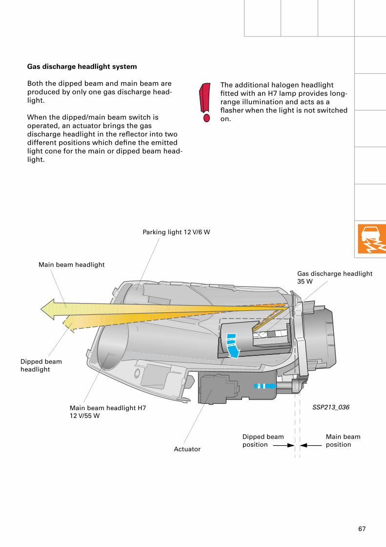
67
Gas discharge headlight system
Both the dipped beam and main beam are produced by only one gas discharge head-light.
When the dipped/main beam switch is operated, an actuator brings the gas discharge headlight in the reflector into two different positions which define the emitted light cone for the main or dipped beam head-light.
SSP213_036
The additional halogen headlight fitted with an H7 lamp provides long-range illumination and acts as a flasher when the light is not switched on.
Gas discharge headlight35 W
Parking light 12 V/6 W
Main beam headlight
Dipped beam headlight
Main beam position
Dipped beam position
Actuator
Main beam headlight H712 V/55 W

68
Special tools
Pressure piece
for crankshaft sealing ring
Order No.T40007
Tensioning roller key
Order No.T40009
Camshaft retainer
Order No.T40005
Extractor for aluminium support link
Swing arm
Order No.T40010
Service
SSP213_007
SSP213_008
SSP213_009
SSP213_010

69
SSP213_016
1
2
3
4
5
6
7
8
9
10
11
1213
14
15
16
17
18
12
Removal/assembly device VAS 5161 forvalve repair (all VW/Audi engines)
VAS 5161/ 1 1 CaseVAS 5161/ 2 1 Thrust fork with lever for mounting cartridgeVAS 5161/ 3 1 DriftVAS 5161/ 4 2 Interlocking fork M6/M8VAS 5161/ 5 2 Interlocking fork M6/M8 with threaded boltVAS 5161/ 6 1 GridVAS 5161/ 7 1 Guide plate, dia. 22, for V8 - 5 VVAS 5161/ 8 1 Assembly cartridge, dia. 22, for 4-cyl. 5 V / 6 cyl. - 5 V / V8 - 5 V /
V 6 - TDI 4 VVAS 5161/ 9 1 Guide plate, dia. 22, for V6 - TDI 4 VVAS 5161/10 1 Sealing pin for VAS 5161/9VAS 5161/11 1 Adapter for compressed air connectionVAS 5161/12 2 M6 knurled head screwVAS 5161/13 1 Guide bush, dia. 22 / 5-valve engines, intake valveVAS 5161/14 1 Guide bush, dia. 22 / 5-valve engines, exhaust valveVAS 5161/15 1 Mounting cartridge, dia. 30 / 2-valve enginesVAS 5161/16 1 Guide bush, dia. 30 / 2-valve enginesVAS 5161/17 1 Spacer ring, dia. 22 for assembly cartridge (V 6 - TDI 4 V)VAS 5161/18 1 Valve insertion device (6 dia. - 7 dia.)

70
Wiper system
Body
SSP213_024
The windscreen wiper system used on the Audi A8 has been redesigned on the driver's side.
The purpose of the revision is to reduce noise levels. This was achieved by using a modified wipe operation.
The wiper blade has an additional pivot point on the windscreen wiper arm which allows it to turn into the headwind earlier.
The noise level is modified with the support of the wind deflector plate and the associated change in the air flow.
The midpoint of the wiper blade continues to follow an orbital path. The path of the wiper blade ends on the other hand is defined by the additional pivot point.
The wiper blade tip initially accelerates more quickly to allow it to end the wipe cycle slowly.
The wiper blade achieves a better, aerody-namic working position in this way.

71
Notes

Service.
For internal use only
All rights reserved.Technical specifications subject to change without notice.
AUDI AGDept. I/VK-5D-85045 IngolstadtFax +49 841/89-36367940.2810.32.20Technical status 02/99Printed in Germany
New Technology ‘99
Design and Function
Self-Study Programme 213
Outlook ‘99
AL 2
Tyre pressure monitoring
TT Roadster
CVT gearbox
Common Rail
V8 5 V engine
213
213