ssp 820333 1.4l 3 4 2014
TRANSCRIPT
Service Training
Self Study Program 820333
The 1.4L EA211 Gasoline EngineDesign and Function

Volkswagen Group of America, Inc.Volkswagen AcademyPrinted in U.S.A.Printed 2/2014
Course Number SSP 820333
©2014 Volkswagen Group of America, Inc.
All rights reserved. All information contained in this manual is based on the latest information available at the time of printing and is subject to the copyright and other intellectual property rights of Volkswagen Group of America, Inc., its affiliated companies and its licensors. All rights are reserved to make changes at any time without notice. No part of this document may be reproduced, stored in a retrieval system, or transmitted in any form or by any means, electronic, mechanical, photocopying, recording or otherwise, nor may these materials be modified or reposted to other sites without the prior expressed written permission of the publisher.
All requests for permission to copy and redistribute information should be referred to Volkswagen Group of America, Inc.
Always check Technical Bulletins and the latest electronic repair information for information that may supersede any information included in this booklet.
Trademarks: All brand names and product names used in this manual are trade names, service marks, trademarks, or registered trademarks; and are the property of their respective owners.

i
Contents
This Self-Study Program provides information regarding the design and function of new models.
This Self-Study Program is not a Repair Manual. This information will not be updated.For maintenance and repair procedures, always refer to the latest electronic service information.
Note Important!
Introduction . . . . . . . . . . . . . . . . . . . . . . . . . . . . . . . . . . . . . . . . . . . . . . . . . . . . 1
Engine Mechanical . . . . . . . . . . . . . . . . . . . . . . . . . . . . . . . . . . . . . . . . . . . . . . 6
Engine Management Systems . . . . . . . . . . . . . . . . . . . . . . . . . . . . . . . . . . . . 36
Service . . . . . . . . . . . . . . . . . . . . . . . . . . . . . . . . . . . . . . . . . . . . . . . . . . . . . . . 53
Knowledge Assessment . . . . . . . . . . . . . . . . . . . . . . . . . . . . . . . . . . . . . . . . . 57

Page intentionally left blank
1
Introduction
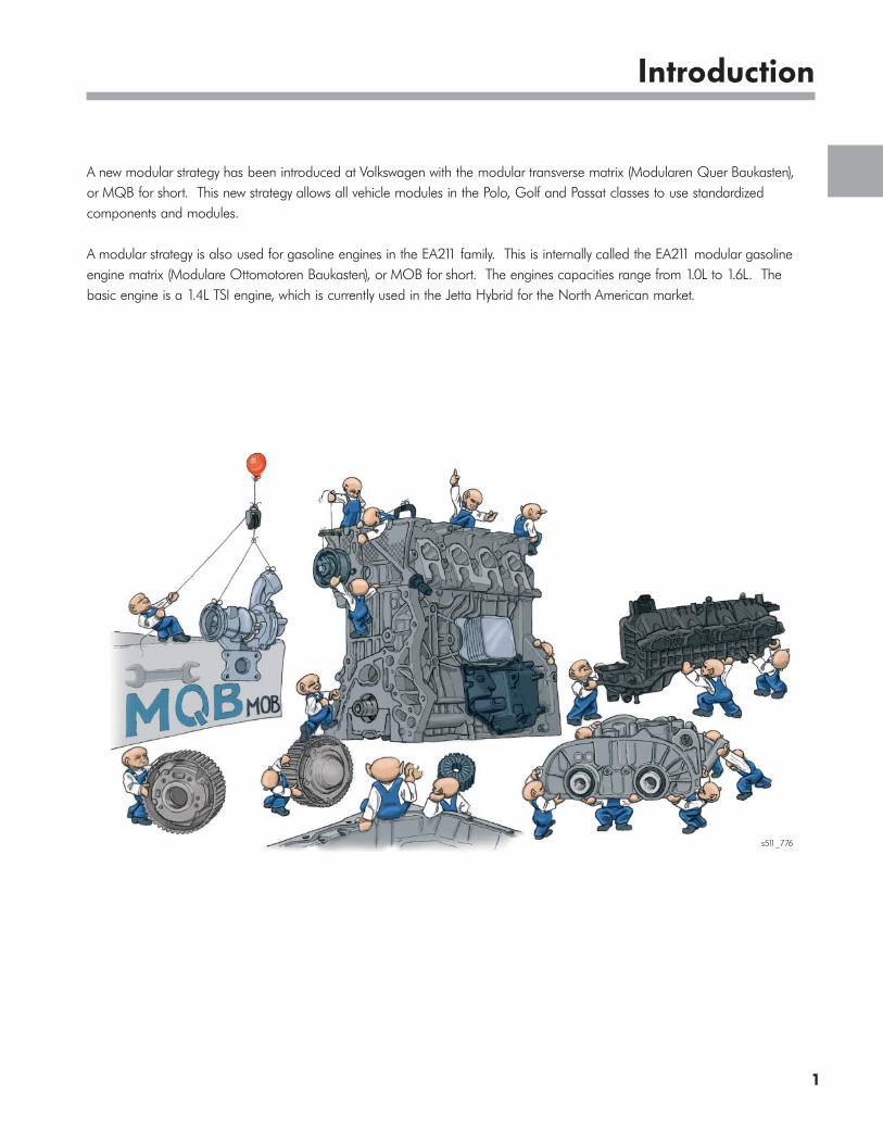
A new modular strategy has been introduced at Volkswagen with the modular transverse matrix (Modularen Quer Baukasten), or MQB for short. This new strategy allows all vehicle modules in the Polo, Golf and Passat classes to use standardized components and modules.
A modular strategy is also used for gasoline engines in the EA211 family. This is internally called the EA211 modular gasoline engine matrix (Modulare Ottomotoren Baukasten), or MOB for short. The engines capacities range from 1.0L to 1.6L. The basic engine is a 1.4L TSI engine, which is currently used in the Jetta Hybrid for the North American market.
s511_776

2
Introduction
Modular Gasoline Engine Matrix MOB The Engine installation Positions in the Vehicle
In the past, the installation position of the engines varied widely. Most Volkswagen Group engines have the exhaust ports facing towards the rear of the vehicle. However, some engines also had the exhaust ports facing out the front of the engine. The new EA211 platform assures that all engines will have components facing the same direction.
This revised installation position allowed the engineers to make improvements to the basic engine structure. Advantages of the new modular strategy are:
• Uniform installation position
• Standardization, e.g. of the transmission connections, cooling system and exhaust system
• Compact engine dimensions
• Tilting the installation position back by 12° reduced the engine depth by 50 mm
s511_128
Golf 6 Adaptations EA211 Engine Family MQB
All Engines
Main feature:
• Cylinder head rotated by 180°
Adaptations:
• Exhaust
• Driveshaft
• Transmission
• Selector Lever
EA111 Engine Family
Other Engines

3
Introduction
EA211 Gasoline Engine Family
This new engine platform provides easy integration of new technologies. However, there are specifications that must apply to the entire platform. These are:
• Modular structure
• Rotated installation position of the engines
• Compact design
• Reduction in consumption and CO2 emissions by 10 - 20%
• Reduction in the engine weight by up to 30%
• Compliance with the future EU6 emission standard
Modular Design of the 1.4L Engine
All engines in the EA211 family have:
• The same installation position
• Air conditioner compressor and alternator bolted directly onto the sump or onto the engine block without brackets
• Four-valve technology
• Aluminium cylinder block
• Exhaust manifold integrated into the cylinder head
• Belt-driven camshaft
Exhaust GasTurbocharger with
Electric Charge PressurePositioner
Cylinder Head
Camshaft Housing
Intake Manifold with Charge Air Cooler
Toothed Belt Drive
Cylinder Block
Two-Section Sump
Accessory Drive
4
Introduction
s511_117
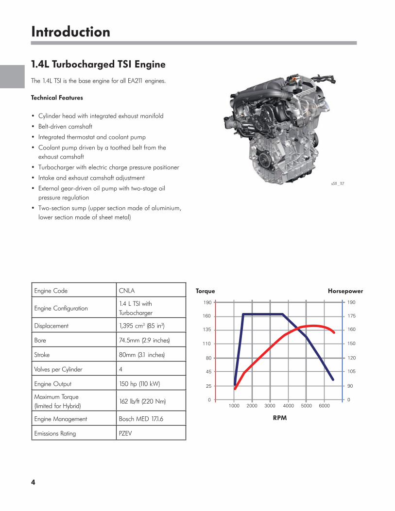
1.4L Turbocharged TSI Engine
The 1.4L TSI is the base engine for all EA211 engines.
Technical Features
• Cylinder head with integrated exhaust manifold
• Belt-driven camshaft
• Integrated thermostat and coolant pump
• Coolant pump driven by a toothed belt from the exhaust camshaft
• Turbocharger with electric charge pressure positioner
• Intake and exhaust camshaft adjustment
• External gear-driven oil pump with two-stage oil pressure regulation
• Two-section sump (upper section made of aluminium, lower section made of sheet metal)
Engine Code CNLA
Engine Configuration1.4 L TSI with Turbocharger
Displacement 1,395 cm3 (85 in3)
Bore 74.5mm (2.9 inches)
Stroke 80mm (3.1 inches)
Valves per Cylinder 4
Engine Output 150 hp (110 kW)
Maximum Torque (limited for Hybrid)
162 lb/ft (220 Nm)
Engine Management Bosch MED 17.1.6
Emissions Rating PZEV
135
160
80
45
25
0
110
190
160
175
120
105
90
0
150
190
1000 2000 3000 4000 5000 6000
Torque Horsepower
RPM

5
Introduction
1.4L TSI for the Jetta Hybrid
This engine is being used in the Jetta Hybrid with the engine code CNLA for the North American Region.
• Alternator and starter functions are performed by the E-machine V141
• Secondary air system (NAR)
• Crankcase breather lines, fuel and evaporative emissions lines are made of different materials to meet North American emission regulations
s511_119
Technical Features
• Crankshaft with teeth for connecting to the three phase current drive VX54 (E-machine)
• Crankshaft vibration damper
• Cylinder block and sealing flange on the transmission side, a port for cooling the E-machine V141 and a port for activating the K0 disengagement clutch
• Electric air conditioning compressor

6
Engine Mechanical
Timing Belt Drive
The camshafts are driven by a toothed timing belt. It is tensioned using an automatic tensioning roller.
An idler roller on the tension side and the special shape of the camshaft sprockets in the 3-cylinder engine, or camshaft gearwheel in the 4-cylinder engine respectively, ensure that the timing belt runs smoothly.
1.4L TSI Engine
Exhaust Camshaft Drive with Adjuster
Intake Camshaft Drive with AdjusterAutomatic Tensioning
Roller
Idler Roller
CTC Crankshaft Sprocket
s511_103
4-Cylinder Engines
Oval CTC crankshaft sprocket
A Crankshaft Torsional Cancellation (CTC) crankshaft sprocket is used in these engines. During the power stroke, the timing belt slackens slightly due to the sprocket’s smaller radius. This reduces tension and lowers the vibrations of the timing belt drive.
Advantages
• Due to CTC, a lower belt tension can be used. This results in lower friction and mechanical stress on the entire timing belt drive
• Reduced vibrations = quieter operation
7
Engine Mechanical
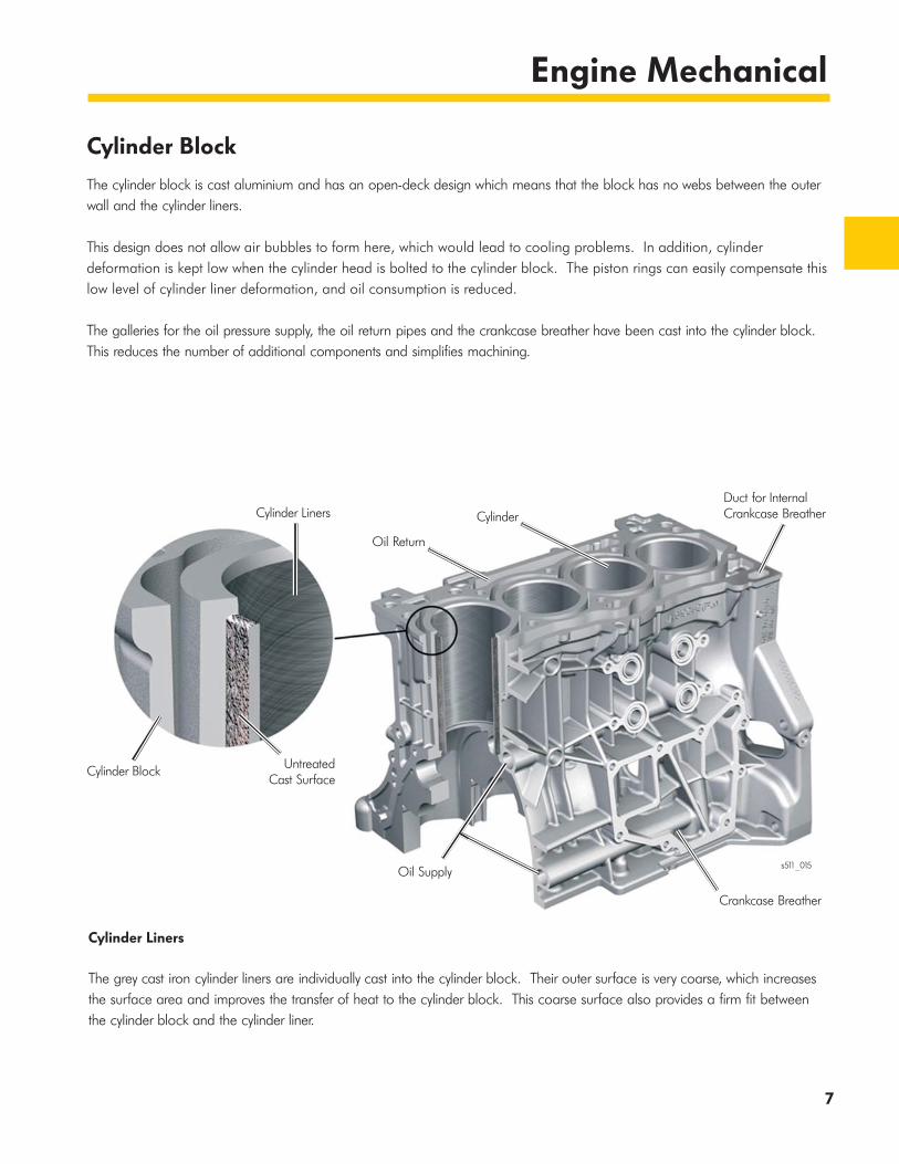
Cylinder Block
The cylinder block is cast aluminium and has an open-deck design which means that the block has no webs between the outer wall and the cylinder liners.
This design does not allow air bubbles to form here, which would lead to cooling problems. In addition, cylinder deformation is kept low when the cylinder head is bolted to the cylinder block. The piston rings can easily compensate this low level of cylinder liner deformation, and oil consumption is reduced.
The galleries for the oil pressure supply, the oil return pipes and the crankcase breather have been cast into the cylinder block. This reduces the number of additional components and simplifies machining.
Cylinder Liners
The grey cast iron cylinder liners are individually cast into the cylinder block. Their outer surface is very coarse, which increases the surface area and improves the transfer of heat to the cylinder block. This coarse surface also provides a firm fit between the cylinder block and the cylinder liner.
Cylinder Liners
Cylinder Block UntreatedCast Surface
Oil Supply
Crankcase Breather
CylinderDuct for InternalCrankcase Breather
Oil Return
s511_015
8
Engine Mechanical
Crankshaft Group
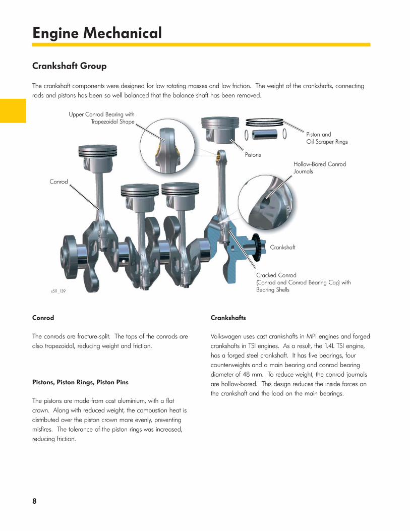
The crankshaft components were designed for low rotating masses and low friction. The weight of the crankshafts, connecting rods and pistons has been so well balanced that the balance shaft has been removed.
Conrod
The conrods are fracture-split. The tops of the conrods are also trapezoidal, reducing weight and friction.
Crankshafts
Volkswagen uses cast crankshafts in MPI engines and forged crankshafts in TSI engines. As a result, the 1.4L TSI engine, has a forged steel crankshaft. It has five bearings, four counterweights and a main bearing and conrod bearing diameter of 48 mm. To reduce weight, the conrod journals are hollow-bored. This design reduces the inside forces on the crankshaft and the load on the main bearings.
Pistons, Piston Rings, Piston Pins
The pistons are made from cast aluminium, with a flat crown. Along with reduced weight, the combustion heat is distributed over the piston crown more evenly, preventing misfires. The tolerance of the piston rings was increased, reducing friction.
Upper Conrod Bearing with Trapezoidal Shape
Conrod
Pistons
Piston and Oil Scraper Rings
s511_139
Cracked Conrod (Conrod and Conrod Bearing Cap) withBearing Shells
Crankshaft
Hollow-Bored ConrodJournals
9
Engine Mechanical
Cylinder Head
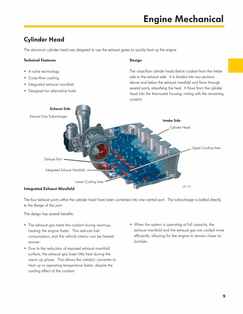
The aluminum cylinder head was designed to use the exhaust gases to quickly heat up the engine.
Technical Features
• 4-valve technology
• Cross-flow cooling
• Integrated exhaust manifold
• Designed for alternative fuels
Integrated Exhaust Manifold
The four exhaust ports within the cylinder head have been combined into one central port. The turbocharger is bolted directly to the flange of this port.
s511_147
This design has several benefits:
• The exhaust gas heats the coolant during warmup, heating the engine faster. This reduces fuel consumption, and the vehicle interior can be heated sooner.
• Due to the reduction of exposed exhaust manifold surface, the exhaust gas loses little heat during the warm-up phase. This allows the catalytic converter to heat up to operating temperature faster, despite the cooling effect of the coolant.
• When the system is operating at full capacity, the exhaust manifold and the exhaust gas are cooled more efficiently, allowing for the engine to remain closer to lambda.
Design
The cross-flow cylinder head directs coolant from the intake side to the exhaust side. It is divided into two sections above and below the exhaust manifold and flows through several ports, absorbing the heat. It flows from the cylinder head into the thermostat housing, mixing with the remaining coolant.
Exhaust Side
Intake SideExhaust Gas Turbocharger
Cylinder Head
Upper Cooling Area
Exhaust Port
Integrated Exhaust Manifold
Lower Cooling Area

10
Engine Mechanical
Camshaft Housing
The camshaft housing is made of cast aluminium and has integrated camshafts. The camshafts are assembled directly into the camshaft housing. Since the cams don’t have camshaft lobes installed before they are inserted into the camshaft housing, the bearing points can be smaller.
Advantages of smaller bearing points
• Lower friction in the bearings
• Higher rigidity
Oil Supply to the Bearing Points
The sleeve bearings receive oil from oil supply holes.
Grooved Ball Bearing
To reduce friction, the first bearing of both camshafts is a grooved ball bearing. This is because of the high load from the timing belt. This bearing cannot be replaced.
s511_150
s511_164
Deep-GrooveBall Bearing
Camshaft Housing
High Pressure FuelPump Drive
Oil Supply Hole
Bearing Point
Cam

11
Engine Mechanical
Valvetrain
The EA211 engine has 4-valve technology. The intake valves have an angle of 21°, and the exhaust valves have an angle of 22.4°. The valves are actuated by roller rocker fingers with hydraulic supporting elements.
Advantages of the 4-valve Technology
• Good cylinder charging and discharging
• High power with small capacity
• Low fuel consumption due to high efficiency
• High torque and pulling power
• Quieter operation
Other Features
• The valve stems have been reduced to a diameter of 5 mm which results in lower moving mass and fewer friction losses due to lower valve spring forces
• The valve seat angle is 90° on the intake side and 120° on the exhaust side, which contributes to an increase in the wear resistance for alternative fuels
s511_151
Hydraulic Supporting Element
Roller Rocker Fingers
Exhaust Camshaft
Exhaust Valve
Intake Valve
Intake Camshaft
12
Engine Mechanical
Variable Valve Timing
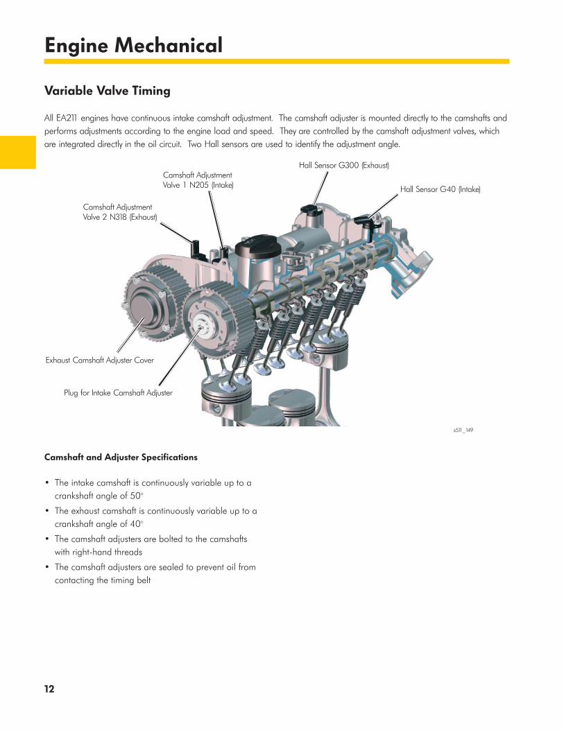
All EA211 engines have continuous intake camshaft adjustment. The camshaft adjuster is mounted directly to the camshafts and performs adjustments according to the engine load and speed. They are controlled by the camshaft adjustment valves, which are integrated directly in the oil circuit. Two Hall sensors are used to identify the adjustment angle.
Camshaft and Adjuster Specifications
• The intake camshaft is continuously variable up to a crankshaft angle of 50°
• The exhaust camshaft is continuously variable up to a crankshaft angle of 40°
• The camshaft adjusters are bolted to the camshafts with right-hand threads
• The camshaft adjusters are sealed to prevent oil from contacting the timing belt
s511_149
Plug for Intake Camshaft Adjuster
Exhaust Camshaft Adjuster Cover
Camshaft Adjustment Valve 2 N318 (Exhaust)
Camshaft Adjustment Valve 1 N205 (Intake)
Hall Sensor G300 (Exhaust)
Hall Sensor G40 (Intake)

13
Engine Mechanical
Vane-type Adjusters
The camshaft adjusters have vanes to control the camshaft position. Depending on which of the two chambers the oil is guided, the rotor turns and the camshaft turns with it. The adjustment is infinite.
Exhaust Camshaft Adjuster Return
To start the engine quickly, there must be no residual gases that can enter the cylinders. As a result, when the engine is shut down, the exhaust camshaft adjuster is locked in the “advanced position” and the intake camshaft adjuster is locked in the “retarded position.”
The exhaust camshaft adjuster is set to a position that is opposite to the direction of engine rotation. Due to the large adjustment angle up to a 40° crank angle, a spring assists the oil pressure to move the adjuster to the advanced position.
Locking
Locking the intake and exhaust camshafts in position prevents adjustment of the camshafts during engine start, allowing for quicker startup. It also prevents noises when the engine is starting.
s511_223
Intake and Exhaust Camshaft Adjustment
The basic design of both camshaft adjusters is identical.
s511_222
Gear Wheel
Housing
Chamber 2
Chamber 1
Rotor
s511_268
Gear Wheel
Housing
Rotor
LockingMechanism
Return Spring
Exhaust Camshaft Adjuster
Return Spring
Adjustment Direction for “Engine off”
14
Engine Mechanical
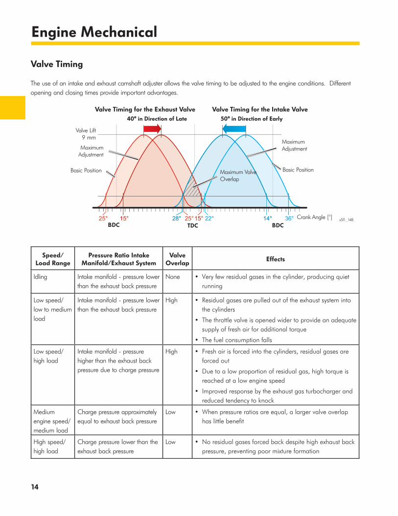
Valve Timing
The use of an intake and exhaust camshaft adjuster allows the valve timing to be adjusted to the engine conditions. Different opening and closing times provide important advantages.
Speed/ Load Range
Pressure Ratio Intake Manifold/Exhaust System
Valve Overlap
Effects
Idling Intake manifold - pressure lower than the exhaust back pressure
None • Very few residual gases in the cylinder, producing quiet running
Low speed/ low to medium load
Intake manifold - pressure lower than the exhaust back pressure
High • Residual gases are pulled out of the exhaust system into the cylinders
• The throttle valve is opened wider to provide an adequate supply of fresh air for additional torque
• The fuel consumption falls
Low speed/ high load
Intake manifold - pressure higher than the exhaust back pressure due to charge pressure
High • Fresh air is forced into the cylinders, residual gases are forced out
• Due to a low proportion of residual gas, high torque is reached at a low engine speed
• Improved response by the exhaust gas turbocharger and reduced tendency to knock
Medium engine speed/ medium load
Charge pressure approximately equal to exhaust back pressure
Low • When pressure ratios are equal, a larger valve overlap has little benefit
High speed/ high load
Charge pressure lower than the exhaust back pressure
Low • No residual gases forced back despite high exhaust back pressure, preventing poor mixture formation
s511_148
Valve Timing for the Exhaust Valve Valve Timing for the Intake Valve40° in Direction of Late 50° in Direction of Early
Crank Angle [°]BDC TDC BDC
Valve Lift9 mm
Basic Position
MaximumAdjustment
Maximum ValveOverlap
Basic Position
MaximumAdjustment
15
Engine Mechanical
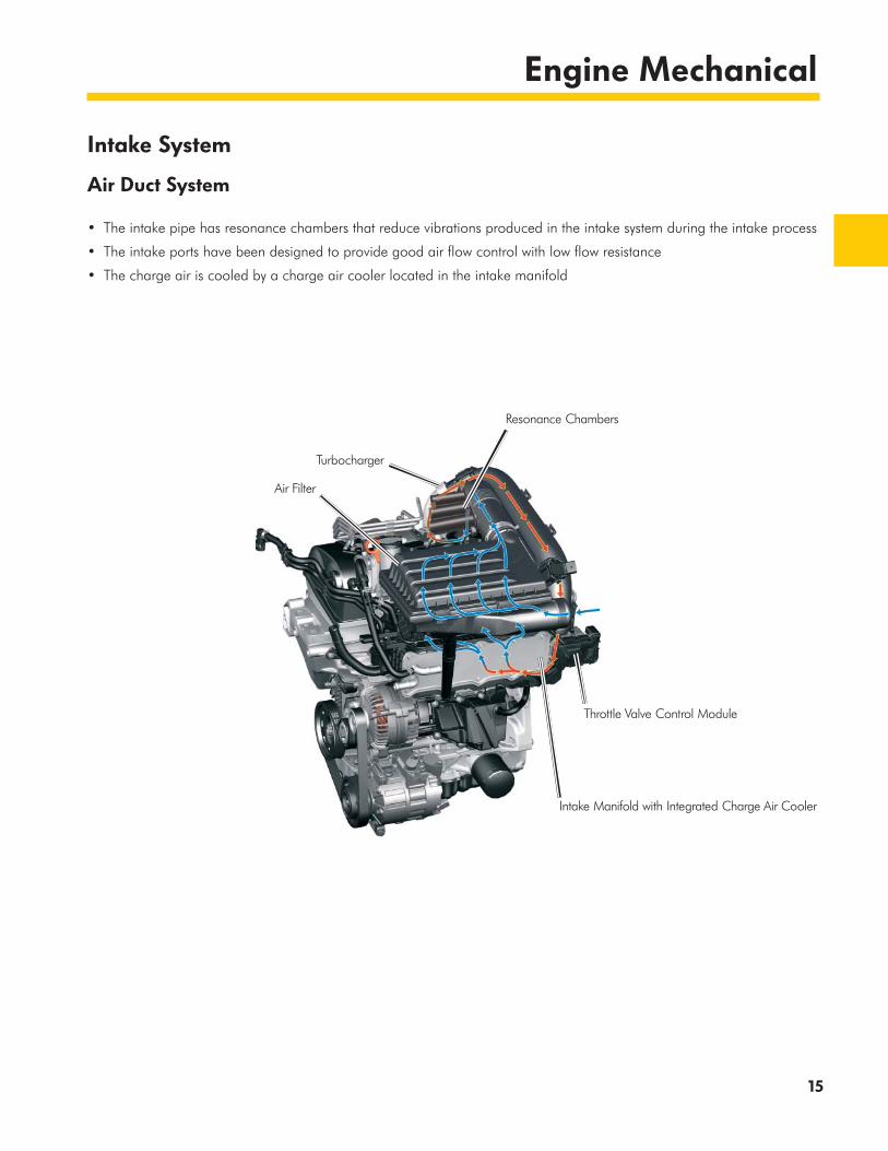
Intake System
Air Duct System
• The intake pipe has resonance chambers that reduce vibrations produced in the intake system during the intake process
• The intake ports have been designed to provide good air flow control with low flow resistance
• The charge air is cooled by a charge air cooler located in the intake manifold
Resonance Chambers
Turbocharger
Throttle Valve Control Module
Intake Manifold with Integrated Charge Air Cooler
Air Filter

16
Engine Mechanical
Turbocharger
The turbocharger is designed for a high torque at low engine speeds and a fast response. This allows the 1.4L TSI engine to reach its maximum torque at just 1500 rpm.
The charge air system is very compact in its design. As a result, the turbocharger has to compress a smaller volume and the charge pressure is reached faster.
Turbocharger
Technical Features:
• Small turbine and compressor wheel diameter with low mass
• Material designed for a maximum exhaust gas temperature of 950 °C
• Integration into the coolant circuit to keep the temperature at the shaft bearings low once the engine has been turned off
• Connection to the oil circuit for lubrication and for cooling the shaft bearings
• Electrical wastegate activation for charge pressure control
s511_168Charge Air Cooler
Charge Air SystemTurbocharger
Wastegate AttachmentCoolant SupplyCoolant Return
Oil LinesCharge PressureActuator
Turbocharger
s511_225
17
Engine Mechanical
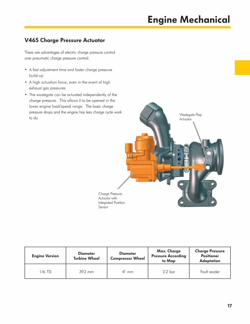
V465 Charge Pressure Actuator
There are advantages of electric charge pressure control over pneumatic charge pressure control:
• A fast adjustment time and faster charge pressure build-up
• A high actuation force, even in the event of high exhaust gas pressures
• The wastegate can be actuated independently of the charge pressure. This allows it to be opened in the lower engine load/speed range. The basic charge pressure drops and the engine has less charge cycle work to do
Engine VersionDiameter
Turbine WheelDiameter
Compressor Wheel
Max. Charge Pressure According
to Map
Charge Pressure Positioner
Adaptation
1.4L TSI 39.2 mm 41 mm 2.2 bar Fault reader
Wastegate Flap Actuator
Charge Pressure Actuator withIntegrated PositionSensor
18
Engine Mechanical
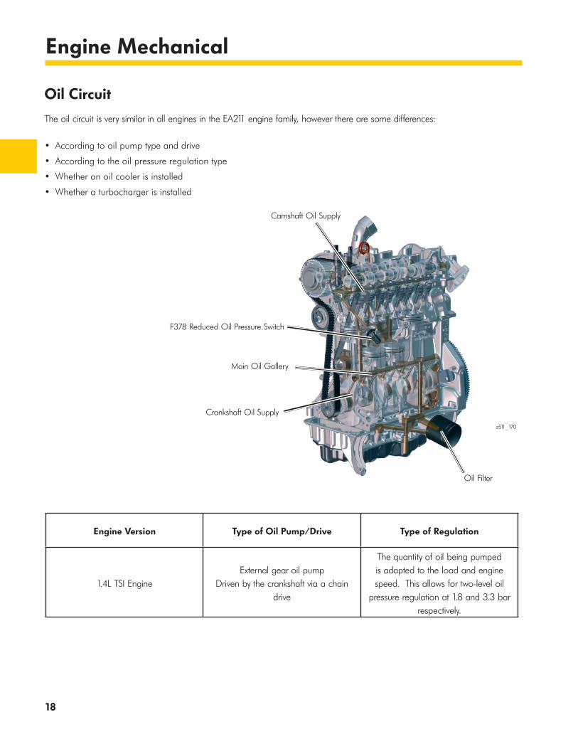
Engine Version Type of Oil Pump/Drive Type of Regulation
1.4L TSI EngineExternal gear oil pump
Driven by the crankshaft via a chain drive
The quantity of oil being pumped is adapted to the load and engine speed. This allows for two-level oil
pressure regulation at 1.8 and 3.3 bar respectively.
Oil Circuit
The oil circuit is very similar in all engines in the EA211 engine family, however there are some differences:
• According to oil pump type and drive
• According to the oil pressure regulation type
• Whether an oil cooler is installed
• Whether a turbocharger is installed
F378 Reduced Oil Pressure Switch
Main Oil Gallery
Crankshaft Oil Supply
Camshaft Oil Supply
Oil Filter
s511_170
19
Engine Mechanical
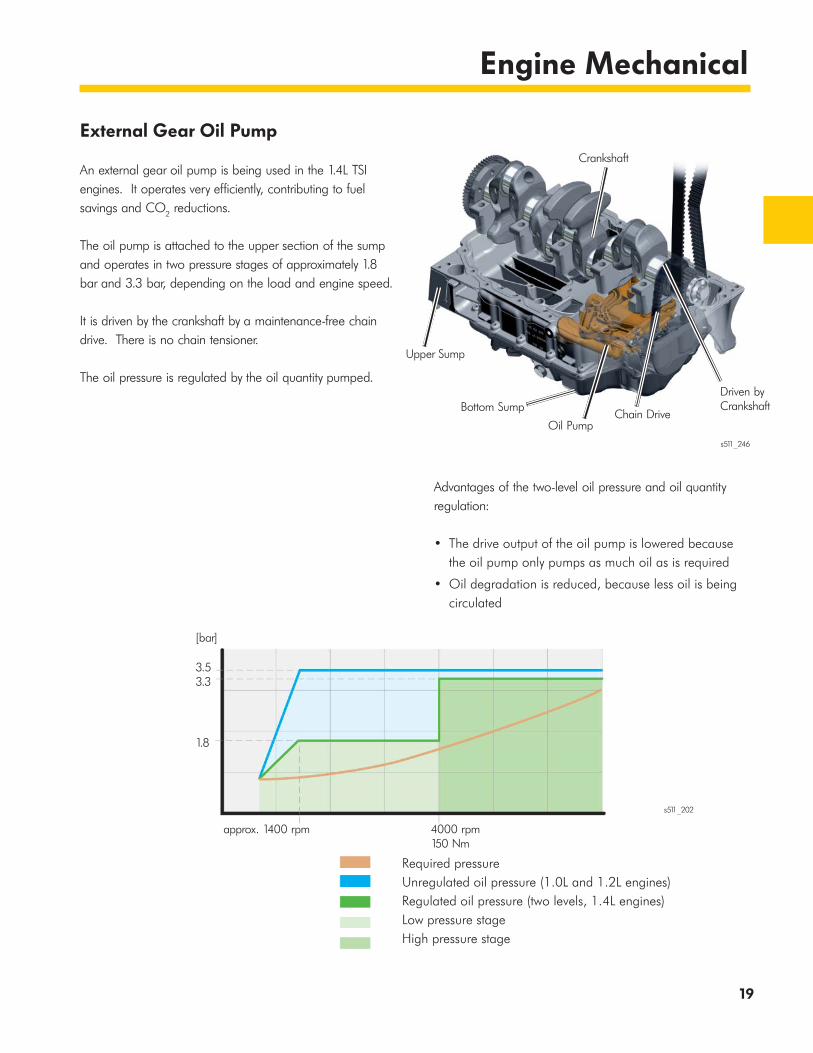
External Gear Oil Pump
An external gear oil pump is being used in the 1.4L TSI engines. It operates very efficiently, contributing to fuel savings and CO2 reductions.
The oil pump is attached to the upper section of the sump and operates in two pressure stages of approximately 1.8 bar and 3.3 bar, depending on the load and engine speed.
It is driven by the crankshaft by a maintenance-free chain drive. There is no chain tensioner.
The oil pressure is regulated by the oil quantity pumped.
Advantages of the two-level oil pressure and oil quantity regulation:
• The drive output of the oil pump is lowered because the oil pump only pumps as much oil as is required
• Oil degradation is reduced, because less oil is being circulated
Required pressureUnregulated oil pressure (1.0L and 1.2L engines)Regulated oil pressure (two levels, 1.4L engines)Low pressure stageHigh pressure stage
3.53.3
1.8
[bar]
approx. 1400 rpm 4000 rpm 150 Nm
s511_202
s511_246
Crankshaft
Upper Sump
Bottom Sump
Oil PumpChain Drive
Driven by Crankshaft
20
Engine Mechanical
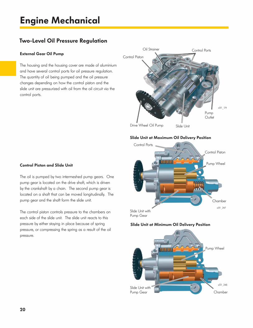
Two-Level Oil Pressure Regulation
External Gear Oil Pump
The housing and the housing cover are made of aluminium and have several control ports for oil pressure regulation. The quantity of oil being pumped and the oil pressure changes depending on how the control piston and the slide unit are pressurized with oil from the oil circuit via the control ports.
Control Piston and Slide Unit
The oil is pumped by two intermeshed pump gears. One pump gear is located on the drive shaft, which is driven by the crankshaft by a chain. The second pump gear is located on a shaft that can be moved longitudinally. The pump gear and the shaft form the slide unit.
The control piston controls pressure to the chambers on each side of the slide unit. The slide unit reacts to this pressure by either staying in place because of spring pressure, or compressing the spring as a result of the oil pressure.
Control Piston
Control Piston
Oil Strainer Control Ports
Control Ports
PumpOutlet
Drive Wheel Oil Pump Slide Unit
Slide Unit at Maximum Oil Delivery Position
Pump Wheel
Slide Unit with Pump Gear
Chamber
Slide Unit at Minimum Oil Delivery Position
Pump Wheel
ChamberSlide Unit with Pump Gear
s511_174
s511_247
s511_248

21
Engine Mechanical
N428 Oil Pressure Regulation Valve
The Oil Pressure Regulation Valve N428 is a ground-controlled valve. It receives a signal from the ECM based on load and engine speed. A valve is used to direct oil and switch between the two oil pressure stages.
The valve has the following switch states:
• If the valve is actuated, it opens the control port to the oil pump and pumps at the low oil pressure stage of 1.8 bar
• If the valve is not actuated, the port is kept closed by spring pressure and the oil pump and pumps at the high oil pressure stage of 3.3 bar
F378 Reduced Oil Pressure Switch and F1 Oil Pressure Switch
The two oil pressure switches are monitored by the ECM. If the oil pressure exceeds a certain threshold, the ECM opens the correct oil pressure switch. This action transmits a message across the CAN-Bus, lighting the K3 Oil Pressure Indicator Lamp in the instrument cluster.
F378
F378 is attached on the intake side, near the timing belt. It is used to monitor low oil pressure.
F1
F1 is attached to the rear of the engine block, in the center. This switch monitors only high pressure.
N428s511_177
s511_178F378
F1s511_228
22
Engine Mechanical
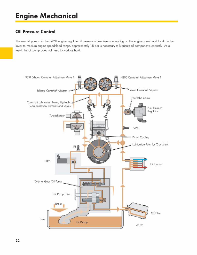
Oil Pressure Control
The new oil pumps for the EA211 engine regulate oil pressure at two levels depending on the engine speed and load. In the lower to medium engine speed/load range, approximately 1.8 bar is necessary to lubricate all components correctly. As a result, the oil pump does not need to work as hard.
N318 Exhaust Camshaft Adjustment Valve 1
Exhaust Camshaft Adjuster
Camshaft Lubrication Points, Hydraulic Compensation Elements and Valves
Turbocharger
F1
N428
External Gear Oil Pump
Oil Pump Drive
Return
SumpOil Pickup
N205 Camshaft Adjustment Valve 1
Intake Camshaft Adjuster
Four-lobe Cams
Fuel PressureRegulator
F378
Piston Cooling
Lubrication Point for Crankshaft
Oil Cooler
Oil Filter
s511_180
23
Engine Mechanical
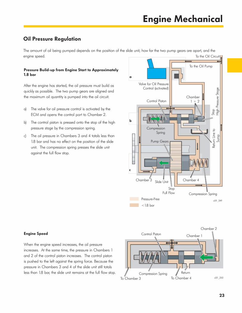
Oil Pressure Regulation
The amount of oil being pumped depends on the position of the slide unit, how far the two pump gears are apart, and the engine speed.
Pressure Build-up from Engine Start to Approximately 1.8 bar
After the engine has started, the oil pressure must build as quickly as possible. The two pump gears are aligned and the maximum oil quantity is pumped into the oil circuit.
a) The valve for oil pressure control is activated by the ECM and opens the control port to Chamber 2.
b) The control piston is pressed onto the stop of the high pressure stage by the compression spring.
c) The oil pressure in Chambers 3 and 4 totals less than 1.8 bar and has no effect on the position of the slide unit. The compression spring presses the slide unit against the full flow stop.
Engine Speed
When the engine speed increases, the oil pressure increases. At the same time, the pressure in Chambers 1 and 2 of the control piston increases. The control piston is pushed to the left against the spring force. Because the pressure in Chambers 3 and 4 of the slide unit still totals less than 1.8 bar, the slide unit remains at the full flow stop.
Pressure-Free
<1.8 bar
To the Oil Circuit
To the Oil Pump
Valve for Oil PressureControl (activated)
Chamber1 + 2Control Piston
a
b
c
Stop
H
igh
Pres
sure
Sta
geRe
turn
Lin
e to
Sum
p
CompressionSpring
Chamber 3 Slide Unit
StopFull Flow
Chamber 4
Compression Spring
s511_249
To Chamber 3 To Chamber 4
Chamber 1
Chamber 2
Compression Spring
Control Piston
Returns511_250
Pump Gears
24
Engine Mechanical
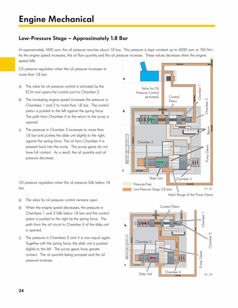
Low-Pressure Stage – Approximately 1.8 Bar
At approximately 1400 rpm, the oil pressure reaches about 1.8 bar. This pressure is kept constant up to 4000 rpm or 150 Nm. As the engine speed increases, the oil flow quantity and the oil pressure increase. These values decrease when the engine speed falls.
Oil pressure regulation when the oil pressure increases to more than 1.8 bar:
a) The valve for oil pressure control is activated by the ECM and opens the control port to Chamber 2.
b) The increasing engine speed increases the pressure in Chambers 1 and 2 to more than 1.8 bar. The control piston is pushed to the left against the spring force. The path from Chamber 4 to the return to the sump is opened.
c) The pressure in Chamber 3 increases to more than 1.8 bar and pushes the slide unit slightly to the right, against the spring force. The oil from Chamber 4 is pressed back into the sump. The pump gears do not have full contact. As a result, the oil quantity and oil pressure decrease.
Oil pressure regulation when the oil pressure falls below 1.8 bar
a) The valve for oil pressure control remains open.
b) When the engine speed decreases, the pressure in Chambers 1 and 2 falls below 1.8 bar and the control piston is pushed to the right by the spring force. The path from the oil circuit to Chamber 4 of the slide unit is opened.
c) The pressure in Chambers 3 and 4 is now equal again. Together with the spring force, the slide unit is pushed slightly to the left. The pump gears have greater contact. The oil quantity being pumped and the oil pressure increase.
Pressure-FreeLow-Pressure Stage (1.8 bar)
a
b
c
Valve for OilPressure Control
(activated)
Chamber 3
Chamber 4
Cha
mbe
r 1
Cha
mbe
r 2Re
turn
Pum
p G
ears
Control Piston
Mesh Range of the Pump Gears
s511_251
Chamber 4
Pum
p G
ears
Cha
mbe
r 2
Cha
mbe
r 1Control Piston
Chamber 3
Slide Unit
Slide Unit
b
c
s511_269
25
Engine Mechanical
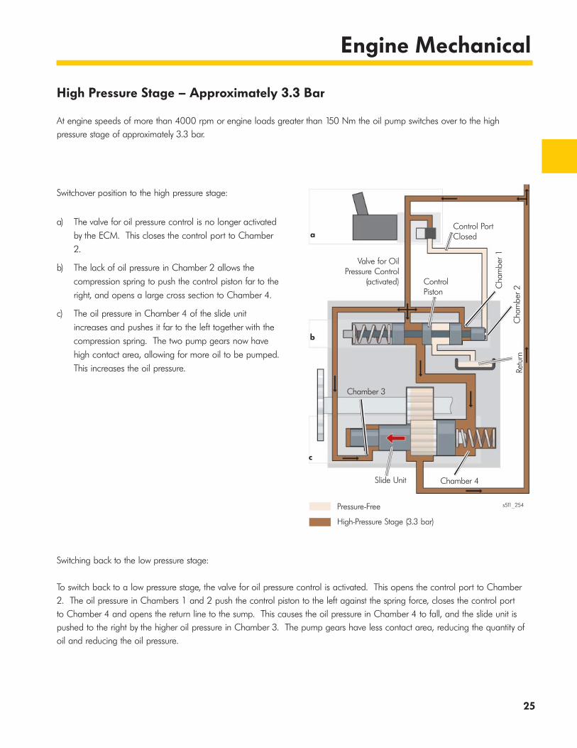
High Pressure Stage – Approximately 3.3 Bar
At engine speeds of more than 4000 rpm or engine loads greater than 150 Nm the oil pump switches over to the high pressure stage of approximately 3.3 bar.
Switchover position to the high pressure stage:
a) The valve for oil pressure control is no longer activated by the ECM. This closes the control port to Chamber 2.
b) The lack of oil pressure in Chamber 2 allows the compression spring to push the control piston far to the right, and opens a large cross section to Chamber 4.
c) The oil pressure in Chamber 4 of the slide unit increases and pushes it far to the left together with the compression spring. The two pump gears now have high contact area, allowing for more oil to be pumped. This increases the oil pressure.
Switching back to the low pressure stage:
To switch back to a low pressure stage, the valve for oil pressure control is activated. This opens the control port to Chamber 2. The oil pressure in Chambers 1 and 2 push the control piston to the left against the spring force, closes the control port to Chamber 4 and opens the return line to the sump. This causes the oil pressure in Chamber 4 to fall, and the slide unit is pushed to the right by the higher oil pressure in Chamber 3. The pump gears have less contact area, reducing the quantity of oil and reducing the oil pressure.
Pressure-Free
High-Pressure Stage (3.3 bar)
a
b
c
Valve for OilPressure Control
(activated)
Chamber 3
Chamber 4
Cha
mbe
r 1
Cha
mbe
r 2Re
turn
Control Piston
Slide Unit
Control PortClosed
s511_254

26
Engine Mechanical
Pressure-Free
High-Pressure Stage (3.3 bar)
High-Pressure Stage – Approximately 3.3 Bar
The oil pressure is regulated at 3.3 bar in the high pressure stage. As the engine speed increases, the oil quantity and the oil pressure continue to increase. The quantity of oil passing through the pump must be adjusted to keep the oil pressure at a constant 3.3 bar.
Oil pressure regulation when the oil pressure increases to more than 3.3 bar
a) The valve for oil pressure control is not activated by the ECM and the control port to Chamber 2 is closed.
b) The oil pressure in Chamber 1 is now high enough to push the control piston to the left against the force of the spring, opening the return port from Chamber 4 to the sump.
c) The pressure in Chamber 4 falls, and the slide unit is pushed to the right against the compression spring by the high oil pressure in Chamber 3. The pump gears no longer have full contact, pumping less oil. The oil pressure falls to approximately 3.3 bar.
a
b
c
Valve for OilPressure Control
(activated)
Chamber 3
Chamber 4C
ham
ber 1
Cha
mbe
r 2Re
turn
Control Piston
Slide Unit
Control PortClosed
27
Engine Mechanical
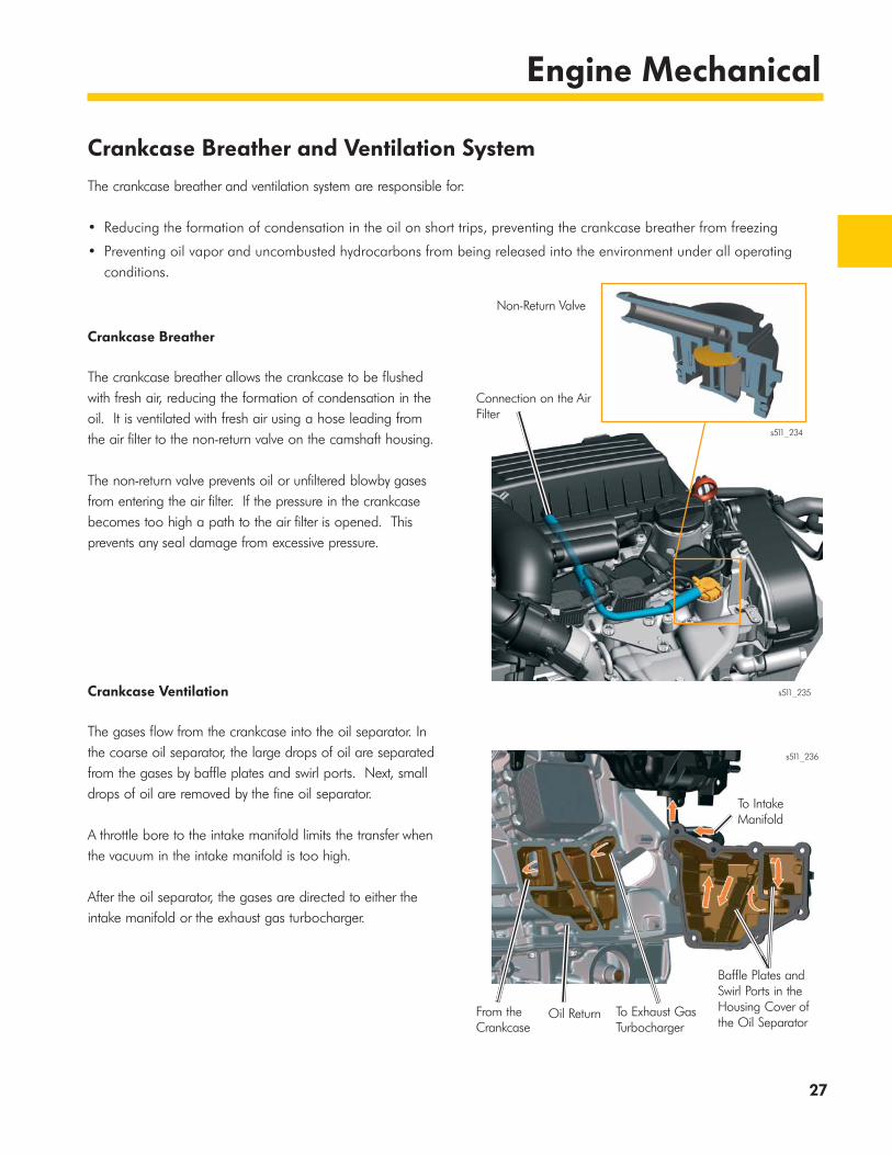
Crankcase Breather and Ventilation System
The crankcase breather and ventilation system are responsible for:
• Reducing the formation of condensation in the oil on short trips, preventing the crankcase breather from freezing
• Preventing oil vapor and uncombusted hydrocarbons from being released into the environment under all operating conditions.
Crankcase Breather
The crankcase breather allows the crankcase to be flushed with fresh air, reducing the formation of condensation in the oil. It is ventilated with fresh air using a hose leading from the air filter to the non-return valve on the camshaft housing.
The non-return valve prevents oil or unfiltered blowby gases from entering the air filter. If the pressure in the crankcase becomes too high a path to the air filter is opened. This prevents any seal damage from excessive pressure.
Crankcase Ventilation
The gases flow from the crankcase into the oil separator. In the coarse oil separator, the large drops of oil are separated from the gases by baffle plates and swirl ports. Next, small drops of oil are removed by the fine oil separator.
A throttle bore to the intake manifold limits the transfer when the vacuum in the intake manifold is too high.
After the oil separator, the gases are directed to either the intake manifold or the exhaust gas turbocharger.
Connection on the AirFilter
Non-Return Valve
s511_234
s511_235
Baffle Plates andSwirl Ports in theHousing Cover ofthe Oil Separator
To IntakeManifold
From the Crankcase
Oil Return To Exhaust GasTurbocharger
s511_236
28
Engine Mechanical
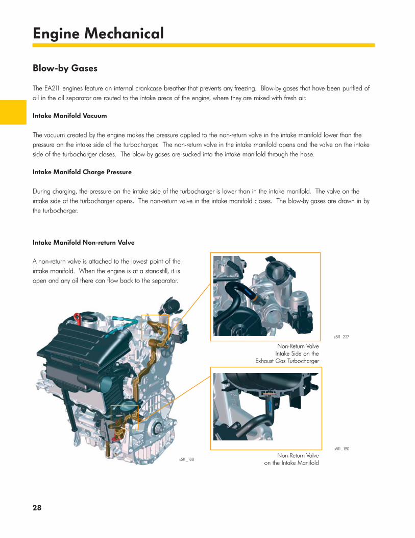
Blow-by Gases
The EA211 engines feature an internal crankcase breather that prevents any freezing. Blow-by gases that have been purified of oil in the oil separator are routed to the intake areas of the engine, where they are mixed with fresh air.
Intake Manifold Vacuum
The vacuum created by the engine makes the pressure applied to the non-return valve in the intake manifold lower than the pressure on the intake side of the turbocharger. The non-return valve in the intake manifold opens and the valve on the intake side of the turbocharger closes. The blow-by gases are sucked into the intake manifold through the hose.
Intake Manifold Charge Pressure
During charging, the pressure on the intake side of the turbocharger is lower than in the intake manifold. The valve on the intake side of the turbocharger opens. The non-return valve in the intake manifold closes. The blow-by gases are drawn in by the turbocharger.
Non-Return ValveIntake Side on the
Exhaust Gas Turbocharger
Non-Return Valveon the Intake Manifold
Intake Manifold Non-return Valve
A non-return valve is attached to the lowest point of the intake manifold. When the engine is at a standstill, it is open and any oil there can flow back to the separator.
s511_188
s511_237
s511_190
29
Engine Mechanical
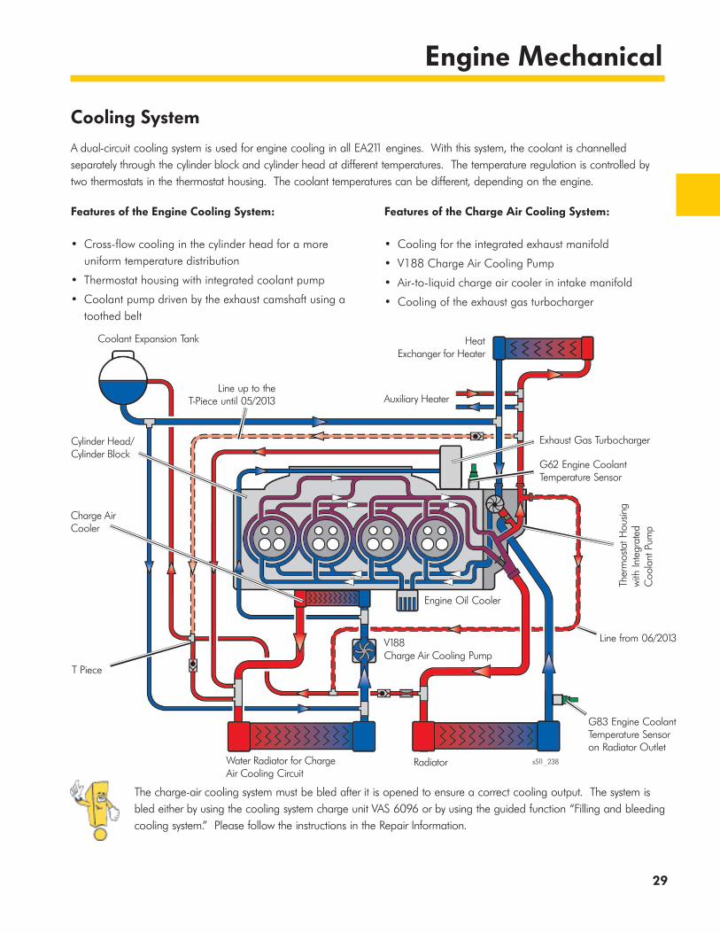
Cooling System
A dual-circuit cooling system is used for engine cooling in all EA211 engines. With this system, the coolant is channelled separately through the cylinder block and cylinder head at different temperatures. The temperature regulation is controlled by two thermostats in the thermostat housing. The coolant temperatures can be different, depending on the engine.
Features of the Engine Cooling System:
• Cross-flow cooling in the cylinder head for a more uniform temperature distribution
• Thermostat housing with integrated coolant pump
• Coolant pump driven by the exhaust camshaft using a toothed belt
Features of the Charge Air Cooling System:
• Cooling for the integrated exhaust manifold
• V188 Charge Air Cooling Pump
• Air-to-liquid charge air cooler in intake manifold
• Cooling of the exhaust gas turbocharger
The charge-air cooling system must be bled after it is opened to ensure a correct cooling output. The system is bled either by using the cooling system charge unit VAS 6096 or by using the guided function “Filling and bleeding cooling system.” Please follow the instructions in the Repair Information.
s511_238
Coolant Expansion Tank HeatExchanger for Heater
V188Charge Air Cooling Pump
Auxiliary Heater
Engine Oil Cooler
Line up to theT-Piece until 05/2013
G62 Engine Coolant Temperature Sensor
Exhaust Gas Turbocharger
Ther
mos
tat H
ousin
gw
ith In
tegr
ated
C
oola
nt P
ump
G83 Engine Coolant Temperature Sensor on Radiator Outlet
Line from 06/2013
Water Radiator for ChargeAir Cooling Circuit
Radiator
Cylinder Head/Cylinder Block
Charge Air Cooler
T Piece

30
Engine Mechanical
Engine Cooling System
The dual-circuit cooling system for the engine pumps the coolant from a coolant pump integrated into the thermostat housing to the cylinder head and cylinder block.
The dual-circuit cooling system has the following advantages:
• The cylinder block warms faster because the coolant remains in the cylinder block until it reaches approximately 105 °C
• Less friction in the crankshaft group due to the higher temperature level in the cylinder block
• Better cooling of the combustion chambers due to the lower temperature level in the cylinder head. This ensures better filling with a lower knocking tendency
Thermostat Housing with Integrated Coolant Pump
The thermostat housing is installed on the cylinder head at the transmission side. The coolant pump has been integrated into the thermostat housing to produce the most compact cooling system design possible. The coolant pump is driven by the exhaust camshaft using a toothed belt.
Cylinder Head Thermostat 1
Thermostat 1 opens at a temperature of 87 °C or above, and opens the path from the radiator to the coolant pump. It opens at a coolant temperature of 80 °C or above in the MPI engines.
Cylinder Block Thermostat 2
Thermostat 2 opens at a temperature of 105 °C or above, and opens the path for the warm coolant from the cylinder block to the radiator. The entire coolant circuit is open.
s511_026
Drive gear on the exhaust camshaft
Thermostat 1
Thermostat 2 s511_200
31
Engine Mechanical
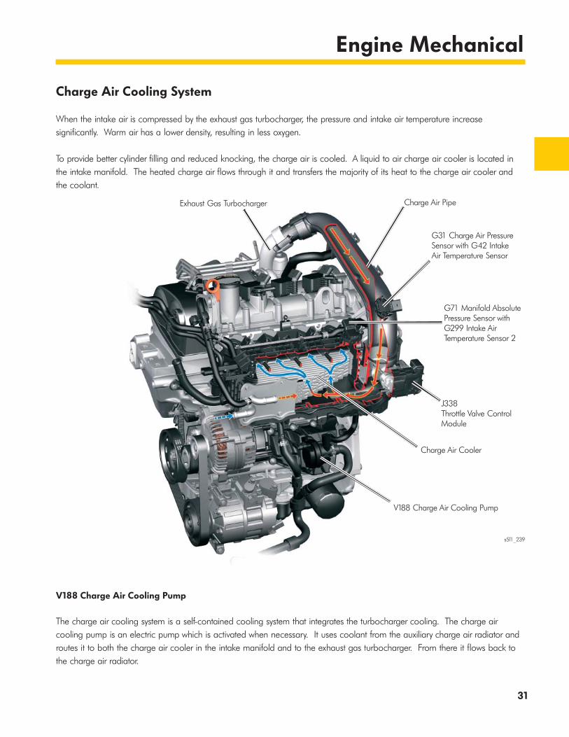
Charge Air Cooling System
When the intake air is compressed by the exhaust gas turbocharger, the pressure and intake air temperature increase significantly. Warm air has a lower density, resulting in less oxygen.
To provide better cylinder filling and reduced knocking, the charge air is cooled. A liquid to air charge air cooler is located in the intake manifold. The heated charge air flows through it and transfers the majority of its heat to the charge air cooler and the coolant.
V188 Charge Air Cooling Pump
The charge air cooling system is a self-contained cooling system that integrates the turbocharger cooling. The charge air cooling pump is an electric pump which is activated when necessary. It uses coolant from the auxiliary charge air radiator and routes it to both the charge air cooler in the intake manifold and to the exhaust gas turbocharger. From there it flows back to the charge air radiator.
s511_239
Exhaust Gas Turbocharger Charge Air Pipe
G31 Charge Air Pressure Sensor with G42 Intake Air Temperature Sensor
G71 Manifold Absolute Pressure Sensor with G299 Intake Air Temperature Sensor 2
J338Throttle Valve Control Module
Charge Air Cooler
V188 Charge Air Cooling Pump

32
Engine Mechanical
Fuel System
The fuel system used for the TSI engines has a low-pressure and a high-pressure fuel system. In addition, the fuel vapors from the activated charcoal filter system are used for combustion.
Low-pressure Fuel System
In the low-pressure fuel system, the fuel is delivered to the high-pressure fuel pump by the electric fuel pump in the fuel tank. The fuel pressure is between 2 and 6 bar, depending on demand.
During normal operation, the fuel pressure is between 2 and 5 bar. When a cold or hot start is made, the pressure is briefly raised to 5 to 6 bar, depending on the engine temperature.
High-pressure Fuel System
In the high pressure fuel system, fuel is pumped from the high pressure fuel pump into the fuel rail. The pressure is measured by the fuel pressure sender and is regulated by the fuel pressure regulating valve between 140 and 200 bar in the 1.4L TSI engines. The fuel is injected by the high pressure injectors.
The high pressure provides good mixture formation and reduces the particle emissions.
s511_240
s511_259
GX1 Fuel Delivery Unit with the G6 Transfer Fuel Pump and Integrated Fuel Filterand Pressure Limiting Valve
Fuel PressureRegulator
Activated CharcoalFilter
Low-Pressure Line to the High PressureFuel Pump
Low-Pressure Line fromFuel Tank
High-PressureFuel Pump
G247 Fuel Pressure Sensor
N30 - N33Cylinder 1 - 4 Fuel Injector
N276Fuel Pressure Regulator Valve

33
Engine Mechanical
Activated Charcoal Filter System
This system is required to reduce the amount of hydrocarbons released into the atmosphere. The system prevents fuel vapors escaping from the fuel tank into the environment. The vapors are stored in an activated charcoal filter. The filter is regularly cleaned and the vapors are routed to the intake manifold or to the intake side of the exhaust gas turbocharger for combustion.
The ECM calculates how much fuel can be supplied from the activated charcoal filter system. The solenoid valve is activated and the injection quantity and throttle valve are adjusted.
The ECM requires the following information:
• Engine load from the G71 Manifold Absolute Pressure Sensor
• Engine speed from the G28 Engine Speed Sensor
• Intake air temperature from the G299 Intake Air Temperature Sensor 2
• Load level of the activated charcoal filter via the G39 Heated Oxygen Sensor
Line from the Activated Charcoal Filter.
Activated Charcoal Filteron the Filler Neck of the
Tank System
EVAP Canister Purge Regulator Valve 1 N80
Inlet on the Intake Manifold
Inlet in Direction ofExhaust Gas Turbocharger
34
Engine Mechanical
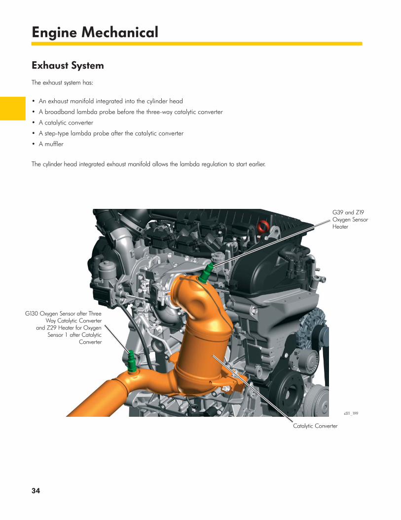
Exhaust System
The exhaust system has:
• An exhaust manifold integrated into the cylinder head
• A broadband lambda probe before the three-way catalytic converter
• A catalytic converter
• A step-type lambda probe after the catalytic converter
• A muffler
The cylinder head integrated exhaust manifold allows the lambda regulation to start earlier.
G130 Oxygen Sensor after Three Way Catalytic Converter
and Z29 Heater for Oxygen Sensor 1 after Catalytic
Converter
G39 and Z19 Oxygen Sensor Heater
Catalytic Converter
s511_199

Page intentionally left blank
36
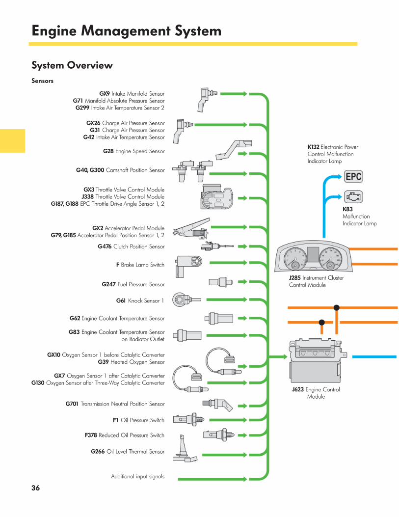
Engine Management System
System Overview Sensors
GX9 Intake Manifold SensorG71 Manifold Absolute Pressure Sensor
G299 Intake Air Temperature Sensor 2
GX26 Charge Air Pressure SensorG31 Charge Air Pressure Sensor
G42 Intake Air Temperature Sensor
G28 Engine Speed Sensor
G40, G300 Camshaft Position Sensor
GX3 Throttle Valve Control ModuleJ338 Throttle Valve Control Module
G187, G188 EPC Throttle Drive Angle Sensor 1, 2
GX2 Accelerator Pedal ModuleG79, G185 Accelerator Pedal Position Sensor 1, 2
G476 Clutch Position Sensor
F Brake Lamp Switch
G247 Fuel Pressure Sensor
G61 Knock Sensor 1
G62 Engine Coolant Temperature Sensor
G83 Engine Coolant Temperature Sensor on Radiator Outlet
GX10 Oxygen Sensor 1 before Catalytic ConverterG39 Heated Oxygen Sensor
GX7 Oxygen Sensor 1 after Catalytic ConverterG130 Oxygen Sensor after Three-Way Catalytic Converter
G701 Transmission Neutral Position Sensor
F1 Oil Pressure Switch
F378 Reduced Oil Pressure Switch
G266 Oil Level Thermal Sensor
Additional input signals
J623 Engine Control Module
J285 Instrument Cluster Control Module
K83 Malfunction Indicator Lamp
K132 Electronic Power Control Malfunction Indicator Lamp

37
Engine Management System
Powertrain CAN bus
J533 Data Bus on Board Diagnostic Interface
Convenience CAN bus
Components with an X in the short designation contain several sensors, actuators or switches in one housing, such as the GX9 with the G71 and the G299.
Additional output signals
VX57 Coolant FanJ293 Coolant Fan Control ModuleV7 Coolant Fan
V188 Charge Air Cooling Pump
N428 Oil Pressure Regulation Valve
V465 Charge Pressure Actuator
N318 Exhaust Camshaft Adjustment Valve 1
N205 Camshaft Adjustment Valve 1
GX7 Oxygen Sensor 1 after Catalytic ConverterZ29 Heater for Oxygen Sensor 1 after Catalytic Converter
GX10 Oxygen Sensor 1 before Catalytic ConverterZ19 Oxygen Sensor Heater
N80 EVAP Canister Purge Regulator Valve 1
N276 Fuel Pressure Regulator Valve
J271 Motronic Engine Control Module Power Supply Relay
GX3 Throttle Valve Control ModuleJ338 Throttle Valve Control ModuleG186 EPC Throttle Drive
N70, N127, N291, N292Ignition Coil 1 - 4 with Power Output Stage
N30 - N33 Cylinder 1 - 4 Fuel Injector
J538 Fuel Pump Control ModuleGX1 Fuel Delivery UnitG6 Transfer Fuel Pump
Actuators

38
Engine Management System
J623 Engine Control Module
The ECM controls all aspects of engine operation, from the intake to the exhaust system. The ECM for this engine also regulates the two-stage oil pressure system.
Engine Engine Management System Connector
1.4L TSI engine Bosch Motronic MED 17.5.21 1 x 60 pins and 1 x 94 pins
Engine Management System Diagnosis
The ECM performs sensor and actuator diagnosis. Exhaust gas-related faults are indicated by the K83 Malfunction Indicator Lamp and functional errors in the system are indicated by the K132 Electronic Power Control Malfunction Indicator Lamp.
Examples of exhaust gas relevant and functional sensors and actuators respectively are the G28 Engine Speed Sensor, the G40 Camshaft Position Sensor and G300 Camshaft Position Sensor 3, the G31 Charge Air Pressure Sensor with the G42 Intake Air Temperature Sensor, the G71 Manifold Absolute Pressure Sensor with the G299 Intake Air Temperature Sensor 2 or the N276 Fuel Pressure Regulator Valve.
In contrast, the K132 is turned on for the F1 Oil Pressure Switch. The K3 Oil Pressure Indicator Lamp is turned on for the F378 Reduced Oil Pressure Switch. If a fault is detected, an entry is made in the event memory.
s511_155

39
Engine Management System
Fuel System
The demand-based fuel system has a low-pressure and a high-pressure fuel system. The fuel delivery is continually adjusted using the electrical fuel pump and the high-pressure fuel pump to reduce excess fuel delivery. This also reduces electrical and mechanical drive power of the fuel pumps, saving fuel.
Low-pressure Fuel System
In the low-pressure fuel system, the pressure is between approximately 2 and 6 bar, depending on the engine map.
During a cold start, higher pressure is used to build up fuel pressure as quickly as possible. During a hot start, higher pressure is used to prevent steam bubbles from forming in the high pressure fuel pump. The temperature in the high pressure fuel pump is calculated by the ECM.
High-pressure Fuel System
In the high-pressure fuel system, the pressure in the 1.4L TSI engine is between 140 and 200 bar, depending on the load and engine speed. This high pressure results in improved vaporization of the injected fuel and an improved mixture formation with fewer exhaust emissions and less soot formation.
The spray pattern of the injectors has also been changed to ensure the injector jet does not hit any components in the combustion chamber.
s511_260
High-Pressure Fuel Pump
Fuel Rail
N276
G247 Fuel Pressure Sensor
Engine Control Module J623
GX1 Fuel Delivery Unit with G6 Transfer Fuel Pump
Fuel Tank
J538 Fuel Pump Control Module
IN30
-N33
Cyli
nder
1-4
Fue
l Inj
ecto
r
Fuel system/low pressure system
High-pressure system Actuator/output signal
Sensor/input signal

40
Engine Management System
Injection Strategies
Different injection strategies are used in all TSI engines. Depending on the coolant temperature, engine speed and engine load of the engine, different injection quantities are injected up to three times per stroke.
Operating Status
Number of
InjectionsAction
Multiple injection high pressure engine start
Coolant temperatures <18°C
Coolant temperature >18°C
3
2
When the engine is started, there are two or three injections per combustion cycle, depending on the coolant temperature. By dividing the fuel quantity for injection up over several injections, the injection time per injection is reduced. This reduces the depth that the fuel jet can penetrate the combustion chamber. Less fuel hits the components in the combustion chamber, the mixture formation is improved and the engine reaches its idling speed faster.
Multiple Injection Catalytic Converter Heating
Engine map
dependent 2 to 3
Multiple injections heat the catalytic converter faster. Thanks to retarded combustion, higher exhaust gas temperatures and mass acts on the catalytic converter. It is heated faster. All of these elements contribute towards reducing exhaust gas emissions and consumption. At the first injection, the majority of the total fuel quantity is injected during the intake cycle. This provides uniform processing of the fuel-air mixture.
Single/multiple injection part load/full load up to 3000 rpm
Engine map
dependent 1 to 3
The single injection takes place in the lowest load range.
Multiple injections from idle speed to full load at up to 3000 rpm ensures a more even mixture preparation. Initial injection takes place before ignition TDC during the intake cycle. Depending on the engine map, 50 - 80% of the total fuel to be injected is injected during the initial injection. The remaining fuel quantity is injected during the second and possibly a third injection. This results in fuel deposited on the cylinder wall. The fuel evaporates almost completely and mixture formation is improved. In addition, the mixture produced in the area of the spark plug is slightly richer than the rest of the combustion chamber. This improves the combustion process and reduces knocking.
EA211 Engine Injection Strategies

41
Engine Management System
Sensors
G31 Charge Air Pressure Sensor and G42 Intake Air Temperature Sensor
The charge pressure sensor with intake air temperature sensor is attached to the pressure pipe just in front of the throttle valve module. It measures the pressure and temperature in this area.
Signal Use
The ECM regulates the turbocharger charge pressure using the signal from the charge pressure sensor. It is regulated via the electrical charge pressure positioner.
The signal from the intake air temperature sensor is required to protect components. If the temperature of the charge air rises above a certain value, the charge pressure is reduced.
The signals from G42 and G299 Intake Air Temperature Sensor 2 are required:
• To activate the charge air cooling pump. If the temperature difference of the charge air before and after the charge air cooler is less than 12 °C, the charge air cooling pump is activated. If it increases to more than 15 °C, the pump is deactivated again
• For a plausibility test of the charge air cooling system. If the temperature difference between the charge air before and after the charge air cooler is too low despite activation of the charge air cooling pump, then it is assumed there is a fault in the charge air cooling system
Effects of Signal Failure
If one or both sensors fail, the turbocharger operation is regulated. The charge pressure is lower and the power is reduced.
s511_206G31 and G42
42
Engine Management System
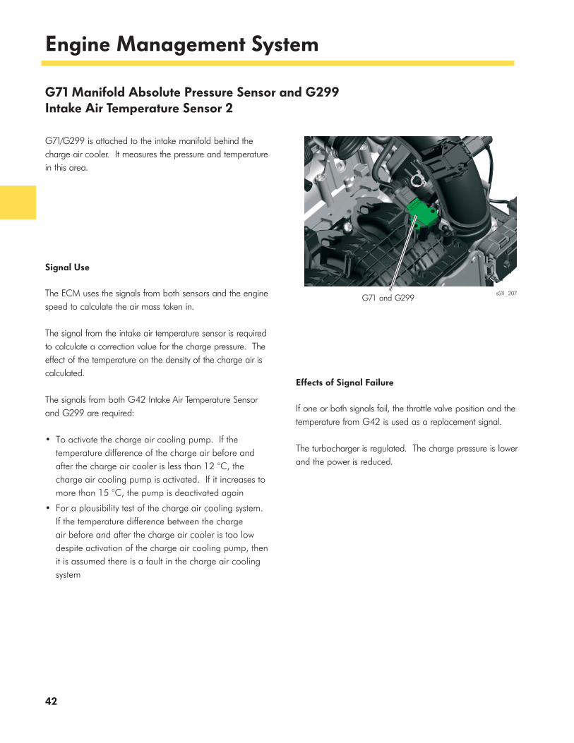
G71 Manifold Absolute Pressure Sensor and G299 Intake Air Temperature Sensor 2
G71/G299 is attached to the intake manifold behind the charge air cooler. It measures the pressure and temperature in this area.
Signal Use
The ECM uses the signals from both sensors and the engine speed to calculate the air mass taken in.
The signal from the intake air temperature sensor is required to calculate a correction value for the charge pressure. The effect of the temperature on the density of the charge air is calculated.
The signals from both G42 Intake Air Temperature Sensor and G299 are required:
• To activate the charge air cooling pump. If the temperature difference of the charge air before and after the charge air cooler is less than 12 °C, the charge air cooling pump is activated. If it increases to more than 15 °C, the pump is deactivated again
• For a plausibility test of the charge air cooling system. If the temperature difference between the charge air before and after the charge air cooler is too low despite activation of the charge air cooling pump, then it is assumed there is a fault in the charge air cooling system
Effects of Signal Failure
If one or both signals fail, the throttle valve position and the temperature from G42 is used as a replacement signal.
The turbocharger is regulated. The charge pressure is lower and the power is reduced.
G71 and G299s511_207
43
Engine Management System
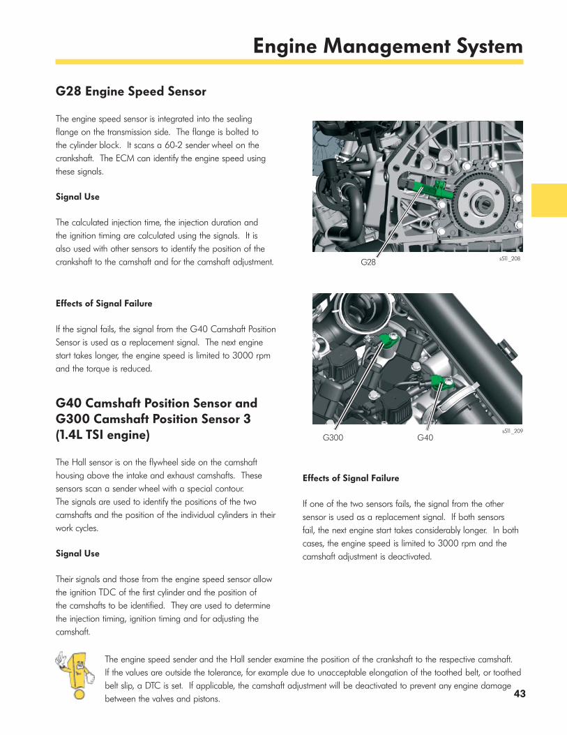
G28 Engine Speed Sensor
The engine speed sensor is integrated into the sealing flange on the transmission side. The flange is bolted to the cylinder block. It scans a 60-2 sender wheel on the crankshaft. The ECM can identify the engine speed using these signals.
s511_208G28
The engine speed sender and the Hall sender examine the position of the crankshaft to the respective camshaft. If the values are outside the tolerance, for example due to unacceptable elongation of the toothed belt, or toothed belt slip, a DTC is set. If applicable, the camshaft adjustment will be deactivated to prevent any engine damage between the valves and pistons.
Effects of Signal Failure
If one of the two sensors fails, the signal from the other sensor is used as a replacement signal. If both sensors fail, the next engine start takes considerably longer. In both cases, the engine speed is limited to 3000 rpm and the camshaft adjustment is deactivated.Signal Use
Their signals and those from the engine speed sensor allow the ignition TDC of the first cylinder and the position of the camshafts to be identified. They are used to determine the injection timing, ignition timing and for adjusting the camshaft.
G300 G40s511_209
Signal Use
The calculated injection time, the injection duration and the ignition timing are calculated using the signals. It is also used with other sensors to identify the position of the crankshaft to the camshaft and for the camshaft adjustment.
Effects of Signal Failure
If the signal fails, the signal from the G40 Camshaft Position Sensor is used as a replacement signal. The next engine start takes longer, the engine speed is limited to 3000 rpm and the torque is reduced.
G40 Camshaft Position Sensor and G300 Camshaft Position Sensor 3 (1.4L TSI engine)
The Hall sensor is on the flywheel side on the camshaft housing above the intake and exhaust camshafts. These sensors scan a sender wheel with a special contour. The signals are used to identify the positions of the two camshafts and the position of the individual cylinders in their work cycles.
44
Engine Management System
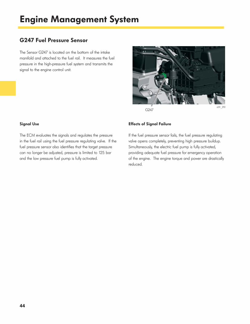
G247 Fuel Pressure Sensor
The Sensor G247 is located on the bottom of the intake manifold and attached to the fuel rail. It measures the fuel pressure in the high-pressure fuel system and transmits the signal to the engine control unit.
Signal Use
The ECM evaluates the signals and regulates the pressure in the fuel rail using the fuel pressure regulating valve. If the fuel pressure sensor also identifies that the target pressure can no longer be adjusted, pressure is limited to 125 bar and the low pressure fuel pump is fully activated.
Effects of Signal Failure
If the fuel pressure sensor fails, the fuel pressure regulating valve opens completely, preventing high pressure buildup. Simultaneously, the electric fuel pump is fully activated, providing adequate fuel pressure for emergency operation of the engine. The engine torque and power are drastically reduced.
s511_210G247
45
Engine Management System
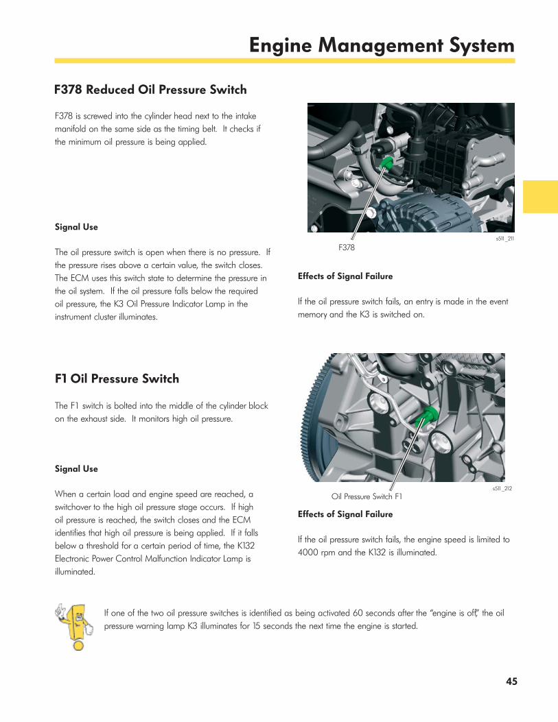
F378 Reduced Oil Pressure Switch
F378 is screwed into the cylinder head next to the intake manifold on the same side as the timing belt. It checks if the minimum oil pressure is being applied.
Signal Use
The oil pressure switch is open when there is no pressure. If the pressure rises above a certain value, the switch closes. The ECM uses this switch state to determine the pressure in the oil system. If the oil pressure falls below the required oil pressure, the K3 Oil Pressure Indicator Lamp in the instrument cluster illuminates.
F378
Effects of Signal Failure
If the oil pressure switch fails, an entry is made in the event memory and the K3 is switched on.
F1 Oil Pressure Switch
The F1 switch is bolted into the middle of the cylinder block on the exhaust side. It monitors high oil pressure.
Signal Use
When a certain load and engine speed are reached, a switchover to the high oil pressure stage occurs. If high oil pressure is reached, the switch closes and the ECM identifies that high oil pressure is being applied. If it falls below a threshold for a certain period of time, the K132 Electronic Power Control Malfunction Indicator Lamp is illuminated.
s511_211
s511_212
Oil Pressure Switch F1
Effects of Signal Failure
If the oil pressure switch fails, the engine speed is limited to 4000 rpm and the K132 is illuminated.
If one of the two oil pressure switches is identified as being activated 60 seconds after the “engine is off,” the oil pressure warning lamp K3 illuminates for 15 seconds the next time the engine is started.
46
Engine Management System
Actuators
J271 Motronic Engine Control Module Power Supply Relay
The J271 relay is installed on the left of the engine compartment in the electronics box.
Task
Using the power supply relay, the ECM can still perform certain functions in run-on mode even after the engine has been turned off (ignition OFF).
In this operating mode, the pressure sensors and some other components can still be monitored. The radiator fan can also be activated.
Effects of Failure
If the J271 relay fails, the corresponding sensors and actuators are no longer triggered. The engine is turned off and can not be started.
s511_270
J271
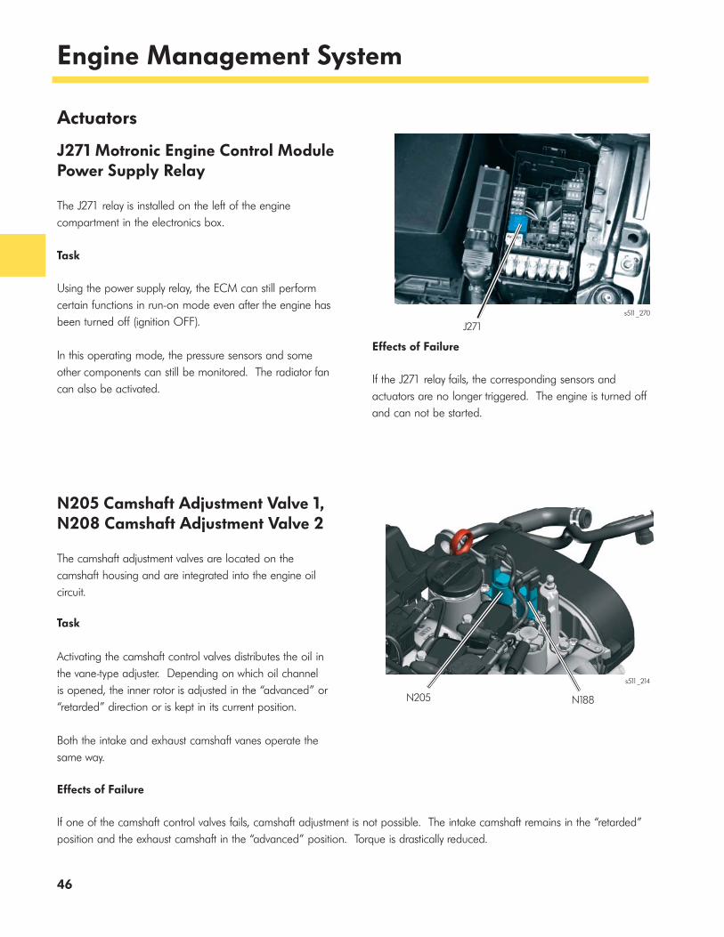
N205 Camshaft Adjustment Valve 1, N208 Camshaft Adjustment Valve 2
The camshaft adjustment valves are located on the camshaft housing and are integrated into the engine oil circuit.
Task
Activating the camshaft control valves distributes the oil in the vane-type adjuster. Depending on which oil channel is opened, the inner rotor is adjusted in the “advanced” or “retarded” direction or is kept in its current position.
Both the intake and exhaust camshaft vanes operate the same way.
Effects of Failure
If one of the camshaft control valves fails, camshaft adjustment is not possible. The intake camshaft remains in the “retarded” position and the exhaust camshaft in the “advanced” position. Torque is drastically reduced.
s511_214
N205 N188
47
Engine Management System
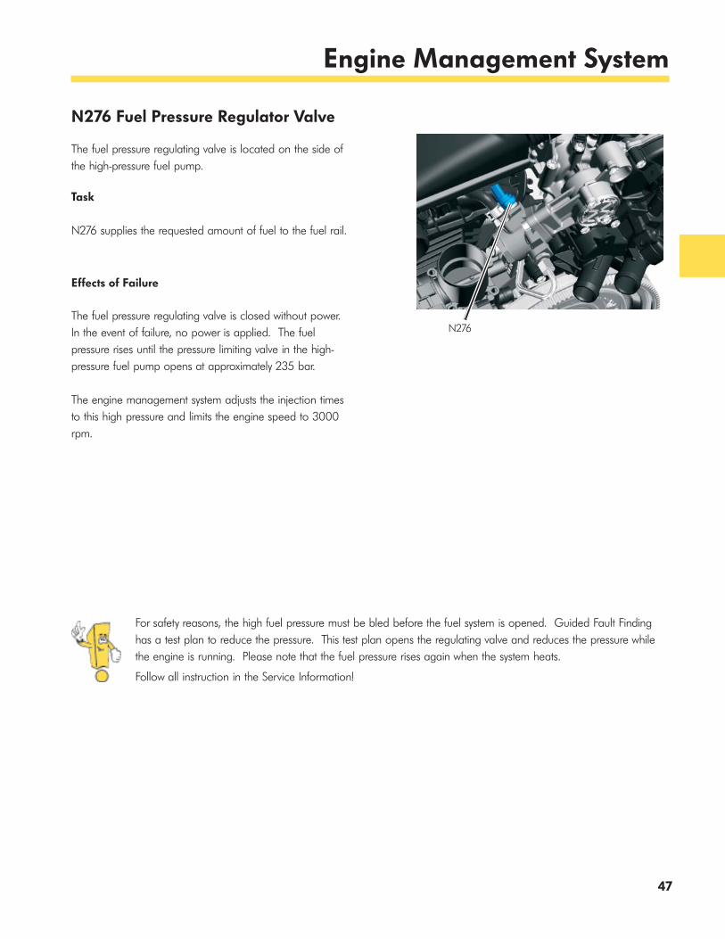
For safety reasons, the high fuel pressure must be bled before the fuel system is opened. Guided Fault Finding has a test plan to reduce the pressure. This test plan opens the regulating valve and reduces the pressure while the engine is running. Please note that the fuel pressure rises again when the system heats.
Follow all instruction in the Service Information!
N276 Fuel Pressure Regulator Valve
The fuel pressure regulating valve is located on the side of the high-pressure fuel pump.
Task
N276 supplies the requested amount of fuel to the fuel rail.
Effects of Failure
The fuel pressure regulating valve is closed without power. In the event of failure, no power is applied. The fuel pressure rises until the pressure limiting valve in the high-pressure fuel pump opens at approximately 235 bar.
The engine management system adjusts the injection times to this high pressure and limits the engine speed to 3000 rpm.
N276
48
Engine Management System
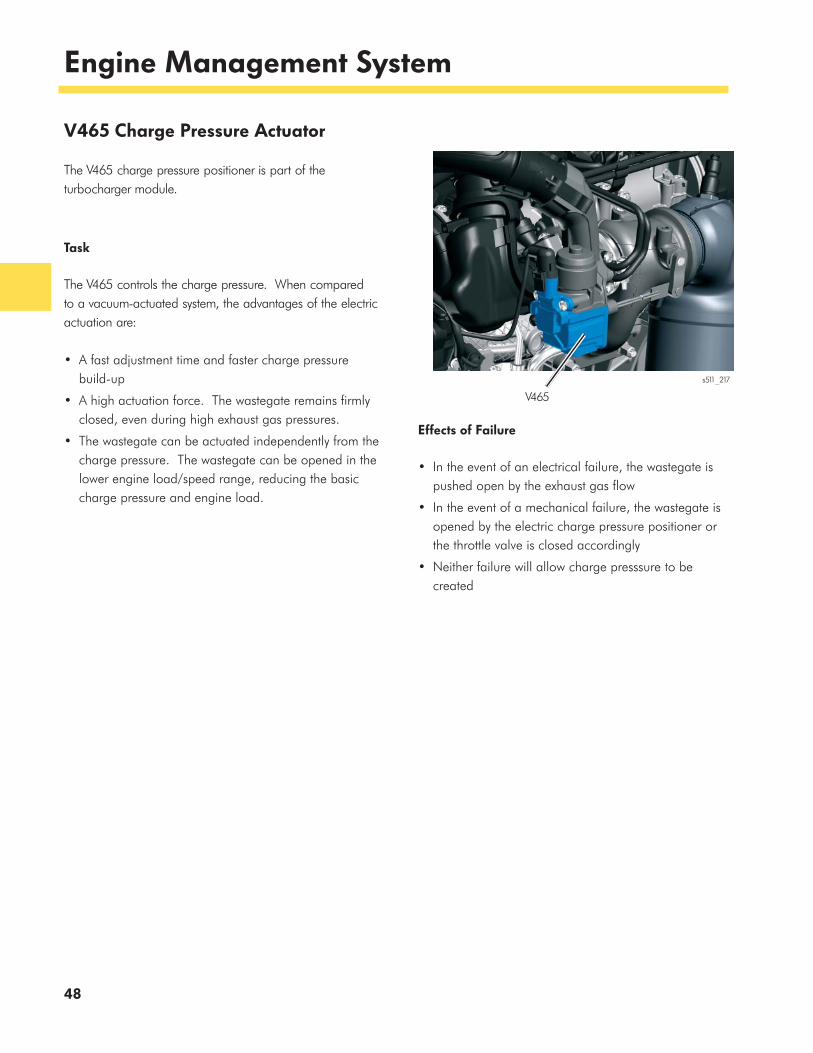
V465 Charge Pressure Actuator
The V465 charge pressure positioner is part of the turbocharger module.
Task
The V465 controls the charge pressure. When compared to a vacuum-actuated system, the advantages of the electric actuation are:
• A fast adjustment time and faster charge pressure build-up
• A high actuation force. The wastegate remains firmly closed, even during high exhaust gas pressures.
• The wastegate can be actuated independently from the charge pressure. The wastegate can be opened in the lower engine load/speed range, reducing the basic charge pressure and engine load.
Effects of Failure
• In the event of an electrical failure, the wastegate is pushed open by the exhaust gas flow
• In the event of a mechanical failure, the wastegate is opened by the electric charge pressure positioner or the throttle valve is closed accordingly
• Neither failure will allow charge presssure to be created
V465
s511_217
49
Engine Management System
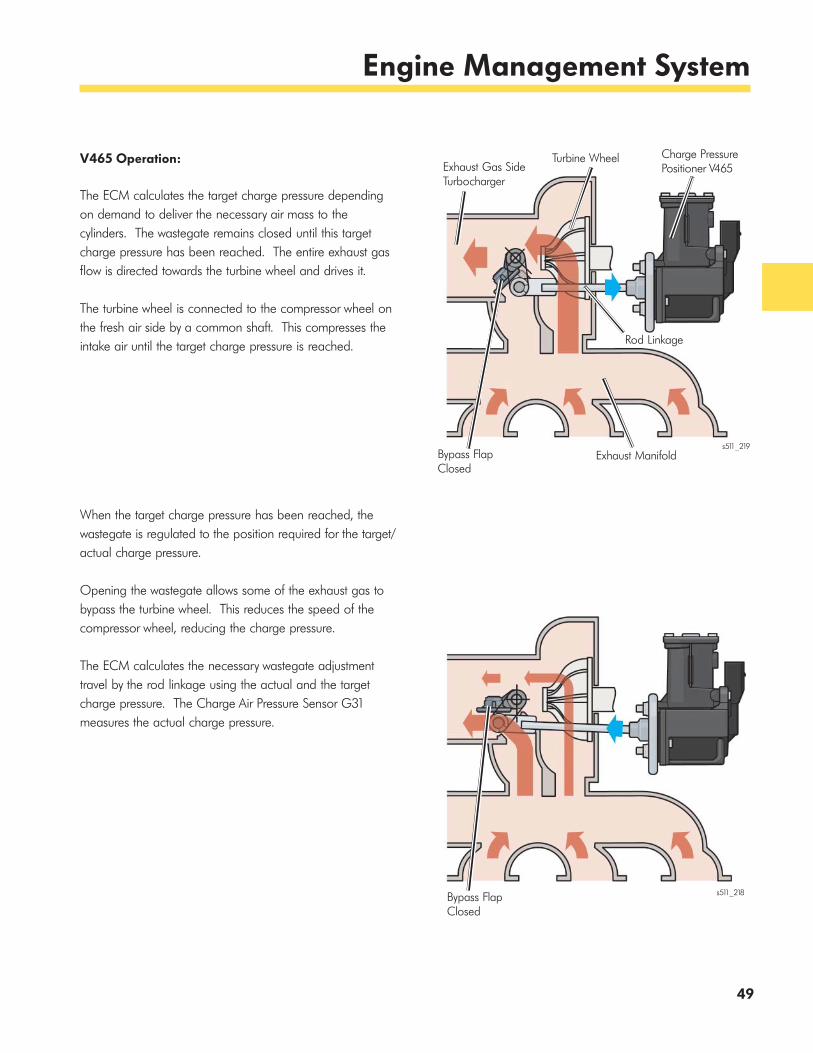
V465 Operation:
The ECM calculates the target charge pressure depending on demand to deliver the necessary air mass to the cylinders. The wastegate remains closed until this target charge pressure has been reached. The entire exhaust gas flow is directed towards the turbine wheel and drives it.
The turbine wheel is connected to the compressor wheel on the fresh air side by a common shaft. This compresses the intake air until the target charge pressure is reached.
When the target charge pressure has been reached, the wastegate is regulated to the position required for the target/actual charge pressure.
Opening the wastegate allows some of the exhaust gas to bypass the turbine wheel. This reduces the speed of the compressor wheel, reducing the charge pressure.
The ECM calculates the necessary wastegate adjustment travel by the rod linkage using the actual and the target charge pressure. The Charge Air Pressure Sensor G31 measures the actual charge pressure.
s511_219
s511_218
Exhaust Gas Side Turbocharger
Turbine Wheel Charge PressurePositioner V465
Rod Linkage
Bypass FlapClosed
Exhaust Manifold
Bypass FlapClosed
50
Engine Management System
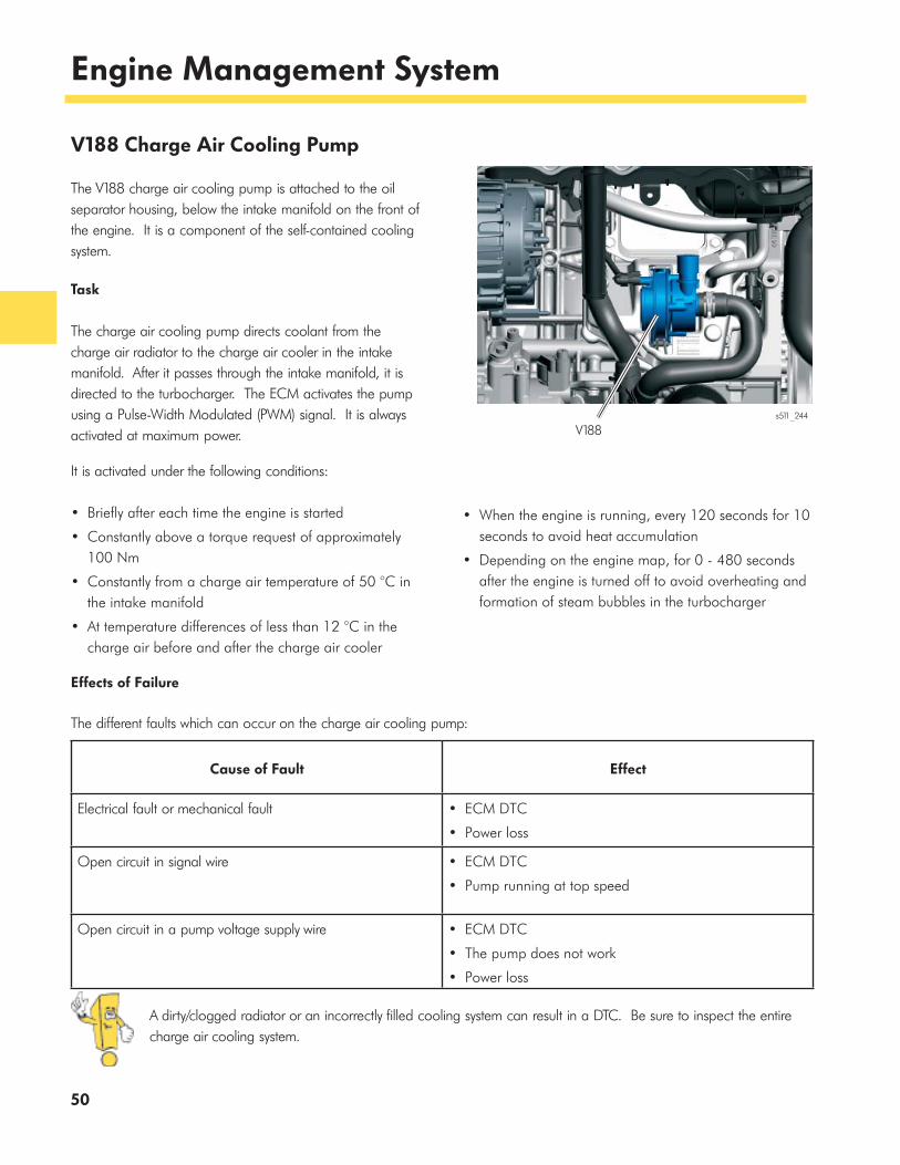
V188 Charge Air Cooling Pump
The V188 charge air cooling pump is attached to the oil separator housing, below the intake manifold on the front of the engine. It is a component of the self-contained cooling system.
Task
The charge air cooling pump directs coolant from the charge air radiator to the charge air cooler in the intake manifold. After it passes through the intake manifold, it is directed to the turbocharger. The ECM activates the pump using a Pulse-Width Modulated (PWM) signal. It is always activated at maximum power.
It is activated under the following conditions:
• Briefly after each time the engine is started
• Constantly above a torque request of approximately 100 Nm
• Constantly from a charge air temperature of 50 °C in the intake manifold
• At temperature differences of less than 12 °C in the charge air before and after the charge air cooler
• When the engine is running, every 120 seconds for 10 seconds to avoid heat accumulation
• Depending on the engine map, for 0 - 480 seconds after the engine is turned off to avoid overheating and formation of steam bubbles in the turbocharger
Cause of Fault Effect
Electrical fault or mechanical fault • ECM DTC
• Power loss
Open circuit in signal wire • ECM DTC
• Pump running at top speed
Open circuit in a pump voltage supply wire • ECM DTC
• The pump does not work
• Power loss
Effects of Failure
The different faults which can occur on the charge air cooling pump:
A dirty/clogged radiator or an incorrectly filled cooling system can result in a DTC. Be sure to inspect the entire charge air cooling system.
V188 s511_244
51
Engine Management System
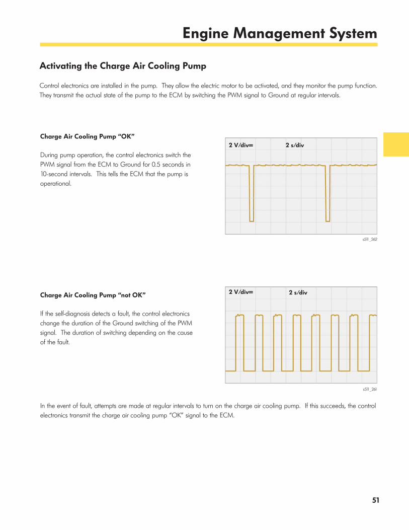
Activating the Charge Air Cooling Pump
Control electronics are installed in the pump. They allow the electric motor to be activated, and they monitor the pump function. They transmit the actual state of the pump to the ECM by switching the PWM signal to Ground at regular intervals.
s511_262
s511_261
2 V/div= 2 s/div
2 V/div= 2 s/divCharge Air Cooling Pump “OK”
During pump operation, the control electronics switch the PWM signal from the ECM to Ground for 0.5 seconds in 10-second intervals. This tells the ECM that the pump is operational.
Charge Air Cooling Pump “not OK”
If the self-diagnosis detects a fault, the control electronics change the duration of the Ground switching of the PWM signal. The duration of switching depending on the cause of the fault.
In the event of fault, attempts are made at regular intervals to turn on the charge air cooling pump. If this succeeds, the control electronics transmit the charge air cooling pump “OK” signal to the ECM.
52
Engine Management System
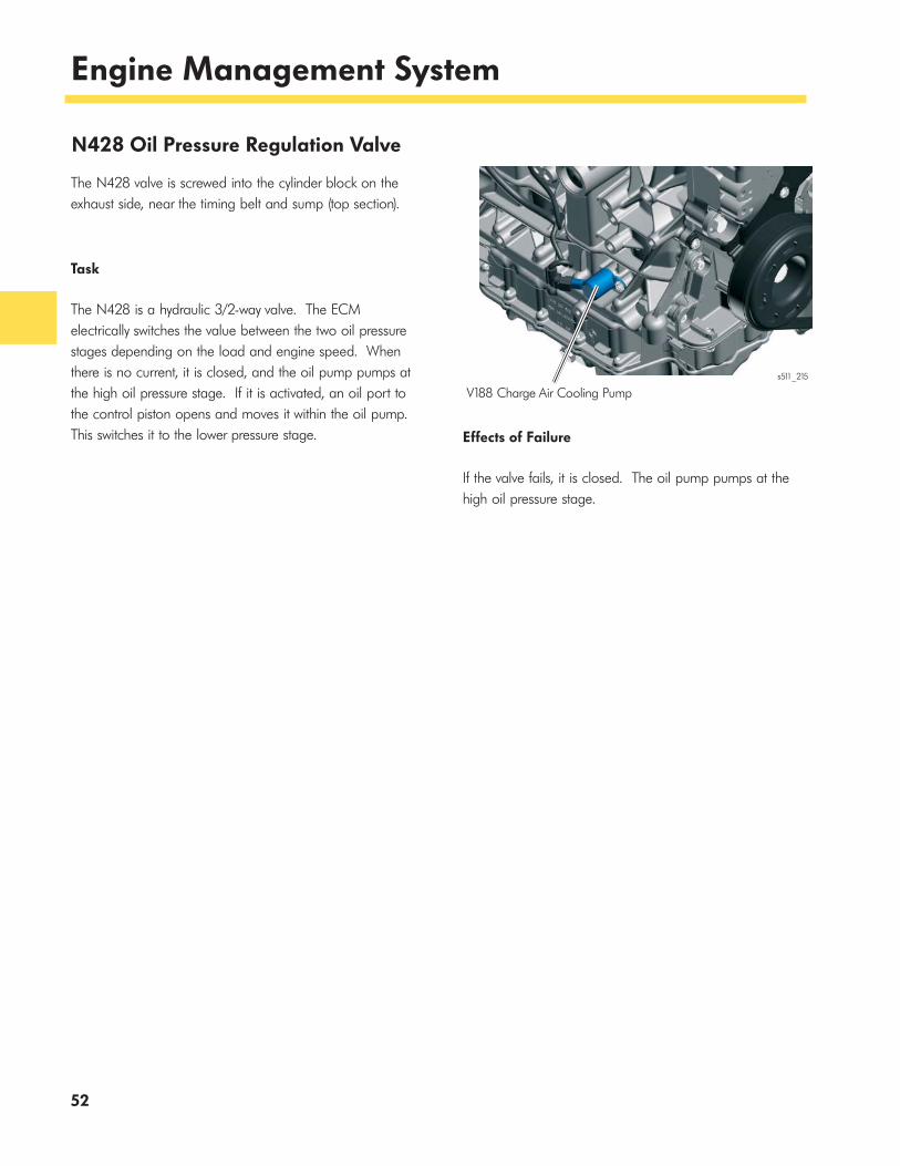
N428 Oil Pressure Regulation Valve
The N428 valve is screwed into the cylinder block on the exhaust side, near the timing belt and sump (top section).
Task
The N428 is a hydraulic 3/2-way valve. The ECM electrically switches the value between the two oil pressure stages depending on the load and engine speed. When there is no current, it is closed, and the oil pump pumps at the high oil pressure stage. If it is activated, an oil port to the control piston opens and moves it within the oil pump. This switches it to the lower pressure stage. Effects of Failure
If the valve fails, it is closed. The oil pump pumps at the high oil pressure stage.
s511_215
V188 Charge Air Cooling Pump
53
Service
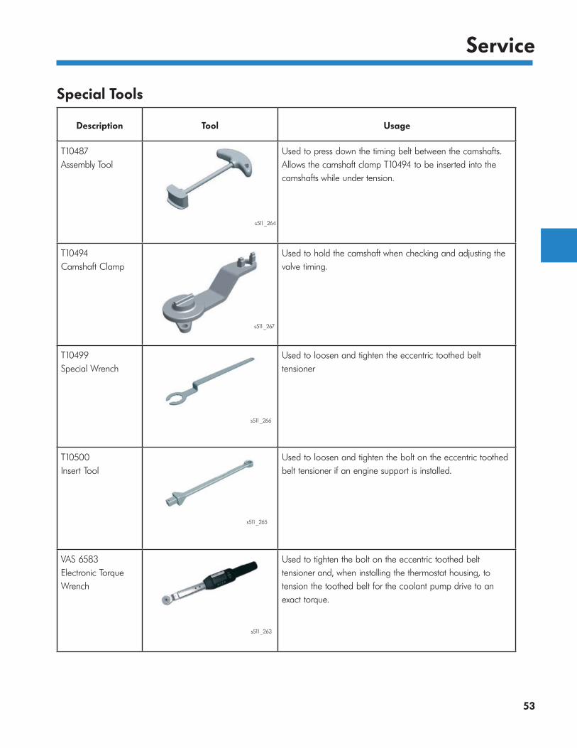
Special Tools
Description Tool Usage
T10487 Assembly Tool
Used to press down the timing belt between the camshafts. Allows the camshaft clamp T10494 to be inserted into the camshafts while under tension.
T10494 Camshaft Clamp
Used to hold the camshaft when checking and adjusting the valve timing.
T10499 Special Wrench
Used to loosen and tighten the eccentric toothed belt tensioner
T10500 Insert Tool
Used to loosen and tighten the bolt on the eccentric toothed belt tensioner if an engine support is installed.
VAS 6583 Electronic Torque Wrench
Used to tighten the bolt on the eccentric toothed belt tensioner and, when installing the thermostat housing, to tension the toothed belt for the coolant pump drive to an exact torque.
s511_264
s511_267
s511_266
s511_265
s511_263

54
Service
Technical Data
Timing Belt Cover
The timing belt is protected from dust and dirt by a three-part toothed belt cover. This extends the service life of the timing belt.
The tensioning roller for the timing belt can be released without having to remove the engine support. The insert T10500, the electronic torque wrench VAS 6583, and other hand tools are required for this procedure. The insert acts like an extension for a standard torque wrench.
Actual tightening specifications are listed on the insert. The bolt can be tightened to the correct torque by entering these specifications into the electronic torque wrench.
Timing Belt
The timing belt must not, under any circumstances, be kinked when doing assembly work, when transporting or storing it. This can damage the tension strands, causing possible engine damage.
s511_104
Timing Belt Tensioning Roller
Plastic Cover withInjection-MoldedSeal
Aluminium-SiliconCover
Plastic Cover withInjection-Molded Seal
s511_134
Backing Material
Tension Strands
Tooth Fabric Made ofPolyamide and Teflon
Timing Belt withTeflon for Reduced Wear

55
Service
Toothed Belt for the Coolant Pump
Before removing the drive wheel, and when tensioning the toothed belt, follow the notes in the Service Information. A correctly tensioned toothed belt allows longer coolant pump life.
To ensure the toothed belt for the coolant pump is correctly tensioned, pretension it to an exact torque using the electronic torque wrench VAS 6583.
Charge Air Cooler Sealing Strip
When installing the charge air cooler, correctly position the sealing strip. If it is not installed properly, vibrations occur, the charge air cooler cracks and is no longer airtight.
Crankshaft Clamp
When adjusting the valve timing, the crank web is only touching the securing bolt.
The crankshaft is not locked and can be rotated against the direction of engine rotation.
CamshaftDrive Gear
Exhaust Camshaft
Toothed Belt
s511_258
CoolantPumpDrive Gear
s511_245Charge Air Cooler Sealing Strip
s511_140
Crank Web
Securing Bolt

Important Links
www.vwwebsource.com
https://www.datarunners.net/vw_crc/default.asp?pageid=home
www.vwhub.com

57
Knowledge Assessment
An on-line Knowledge Assessment (exam) is available for this Self-Study Program.
The Knowledge Assessment may or may not be required for Certification.
You can find this Knowledge Assessment at:
www.vwwebsource.com
For Assistance, please call:
Volkswagen Academy
Certification Program Headquarters
1-877-791-4838
(8:00 a.m. to 8:00 p.m. EST)
Or, E-mail:

Volkswagen Group of America2200 Ferdinand Porsche DriveHerndon, VA 20171February 2014