ssina ss fabrication - designer handbook 2001
DESCRIPTION
SS Fabrication - Designer Handbook 2001TRANSCRIPT

STAINLESS
STEEL
FABRICATION
HANDBOOK
D E S I G N E R
StainlessSteel
TheValueOption®
3819 Fabrication 6/22/01 2:57 PM Page 3

TABLE OF CONTENTSGeneral..................................................1
Characteristics of Stainless Steel ........2Fabrication Properties........................2
Drilling ...................................................2Cutting...................................................2
Mechanical ........................................3Shearing.........................................3Circle Shearing...............................4Sawing ...........................................4Blanking, Punching,
and Nibbling...............................5Abrasive Cutting.............................6
Thermal..............................................6Flux Cutting ....................................6Arc Cutting .....................................7Plasma Arc Cutting.........................7
Bending.................................................8Springback ........................................8Types.................................................9
Press Brakes ..................................9Roll Bending...................................9Roll Forming...................................9Stretch Forming............................10
Descaling ............................................10Removal of Oxide Scale...................10
Pickling Solutions .........................10Blasting ........................................10
Removal of Weld Discoloration ........10Passivation ..........................................10Finishing..............................................11
Grinding, Polishing & Buffing ...........11Care in the Shop..................................11
Handling ..........................................11Contamination..................................12
Cleaning ..............................................12Rust Contamination..........................12Cleaning Methods............................12
The Specialty Steel Industry of NorthAmerica (SSINA) and the individual companies it represents have madeevery effort to ensure that the informationpresented in this handbook is technicallycorrect. However, neither the SSINA norits member companies warrants theaccuracy of the information contained in this handbook or its suitability for anygeneral and specific use. The SSINAassumes no liability or responsibility ofany kind in connection with the use ofthis information. The reader is advisedthat the material contained herein shouldnot be used or relied on for any specificor general applications without firstsecuring competent advice.
4-99-5

1
GENERALStainless steel is not a single alloy, but rather the name applies to a group of iron
based alloys containing a minimum of 10.5% chromium. Other elements are added andthe chromium content increased to improve the corrosion resistance, improve heat resist-ing properties, enhance mechanical properties, and/or to improve fabricating characteris-tics. There are over 50 stainless steel grades that were originally recognized by theAmerican Iron and Steel Institute (AISI) and are detailed in a designer handbook, DesignGuidelines for the Selection and Use of Stainless Steel, available from the Specialty SteelIndustry of North America (SSINA).
This booklet on the fabrication of stainless steel will only deal with 30 of the more com-mon grades in three metallurgical groups: austenitic, ferritic, and martensitic.
AUSTENITIC GROUPThis group contains chromium and nickel and is identified by the Type 300 series.
Grades containing chromium, nickel, and manganese are Type 200. These two typeshave different compositions and properties, but many common characteristics. Theycan be hardened by cold working, but not by heat treatment. In the annealed condition,all are essentially nonmagnetic. They have excellent corrosion resistance and unusuallygood formability. Type 304 (18% chromium - 8% nickel) and Type 316 (16% chromium -10% nickel - 2% molybdenum) are the most widely used grades in this group.
FERRITIC GROUPThe ferritic stainless steels are identified by the Type 400 series. They cannot be
hardened by heat treatment. They are straight chromium alloys and only moderatelyhardened by cold working. This group is magnetic and has good ductility and resist-ance to corrosion. Type 430 (16% chromium) is the general purpose stainless steel ofthe ferritic group.
MARTENSITIC GROUP This group is also identified by the Type 400 series and are hardenable by heat
treatment. They are magnetic and resist corrosion in mild environments. The ductility ofthis group is fair to good. Type 410 (11.5% chromium) is the most widely used alloy ofthis group.
ACKNOWLEDGMENTThe Specialty Steel Industry of North America wishes to acknowledge information
obtained from the International Nickel Company, the Southern Africa Stainless SteelDevelopment Association, the Steel Service Center Institute and the Nickel DevelopmentInstitute (NiDI) as having contributed to this publication.
3819 Fabrication 6/22/01 2:57 PM Page 5

2
Exhibit 1RELATIVE FABRICATION CHARACTERISTICS OF STAINLESS STEELS
Group Austenitic Ferritic Martensitic
201, 202, 316301, 302, 316L 405304, 304L 309S 317 321 430 442 403 440A
Type Number 305 303* 310S 317LMN 347 439 446 410 420 440C
Air Hardening No No No No No No No Yes Yes YesBlanking F F F F F E E E E GBrazing, Silver G – G G G G G G G GBuffing G – G G G G G G G GDrawing, Deep E – G E G E F E NR NRForming, Hot G F G G G G G G G GForming, Cold G F G G G G F G F NRGrinding, Ease of F G F F F F F G E EGrinding (magnetic) No No No No No Yes Yes Yes Yes YesHardenable by
Heat Treatment No No No No No No No Yes Yes YesPunching (perforating) F – F F F G G G G GPolishing G G G G F G G G G GRiveting, Hot G F G G G G G G NR NRRiveting, Cold G F G G G G G G NR NRShearing, Cold F F F F F G G G G FSoldering G G G G G G G G G GBrazing G G G G G G G G G GSpinning G – G G G G F F NR NRWelding E NR E E E F F F F FMachining F E F F F G F G F NR
Code: E = Excellent G = Good F = Fair NR = Not generally recommended (Poor)
CHARACTERISTICS OFSTAINLESS STEEL
Stainless steels can be fabricated bymethods similar to those used for carbonsteels and other common metals. How-ever, changes may be necessary to theextent that they differ in yield strengthand rate of work hardening. All havework hardening rates higher than com-mon carbon steels, but the austeniticsare characterized by large increases instrength and hardness with cold work.With the exception of the resulfurized“free-machining” grades (Type 303 is thecommon type, but many others can betreated to be more easily machined), allstainless steels are suitable for crimpingor flattening operations. The free machin-ing grades will withstand mild longitudi-nal deformation, but may exhibit sometendency to splitting. In spite of theirhigher hardness, most martensitic andall of the ferritic types can be success-fully fabricated. Exhibit 1 shows the rela-tive fabrication characteristics of threegroups of stainless steel.
*Chemistry designed for improved machining (as are other grades, i.e., 416, 420F, 430F, 440F)
FABRICATION PROPERTIES OFSTAINLESS STEEL
Exhibit 2 lists the 30 grades and theirUNS number (the Unified NumberingSystem was developed by the AmericanSociety for Testing Materials and theSociety of Automotive Engineers for allcommercial metals and alloys). Somestainless types are not suitable for certainapplications and others are designed tobe better adapted. Exhibit 2 shows thesuitability of these 30 types in variousfabrication applications.
CUTTINGImportant Note: In all cutting opera-
tions on stainless steels the followingguidelines are helpful in maintaining corrosion resistance:
• No contamination by ferrous (iron orsteel) material or particles shouldtake place.
• Mechanically cut edges will naturallyform the corrosion resistant passivefilm. The formation of such a passivefilm on cut edges will be enhancedby a chemical (acid) passivationtreatment with nitric acid.
• Thermally cut edges may be affectedin terms of chemical compositionand metallurgical structure. Removalof affected surface layers by dress-ing is necessary so that impairedareas of mechanical and corrosionresistant properties are minimized.
Cutting operations are usually neces-sary to obtain the desired blank shape orsize prior to forming operations and alsoto trim a part to final size. Mechanicalcutting and thermal cutting are the twomost frequently used cutting operationsand the specific methods available arediscussed in the individual sections below.These methods are useable with stain-less steel, but because of the differencesin strength, toughness and rate of workhardening, certain details in the opera-tions may need to be modified relative tocarbon steels.
DRILLINGAll stainless steels have “work” (or
strain) hardening characteristics. It is particularly notable in the 300 series.When the drill bits contact the surface ofthe stainless steel and as they penetrate,the material will harden and it will bemore and more difficult to continuedrilling with the same pressure andspeed. Drilling bits are generally madefrom high speed steels and monolithiccarbide. It is important to lubricate thedrill under pressure. Soluble oils or cutting oils are often used (it is advisableto seek professional recommendationson specific oils that are available for usewith stainless steel).
For long products and thick sheetsand plates, the point angle should be120 to 135 degrees. For thin sheets, inorder to reduce the surface stresses, thepoint angle should be increased to 140degrees and the relief angle reduced to5 degrees*
*As stated in “Working with StainlessSteels” by Pierre-Jean CUNAT SIRPEpublisher.

3
MECHANICALShearing
The shear strength of annealedaustenitic stainless steel is about 65 to70 percent of its ultimate tensile strength.The shear strength of carbon steel is inthe range of 55 to 60 percent of its ultimatestrength. Generally, shears are rated ontheir capacity to shear mild carbon steelof 50 ksi tensile strength. The shears aresupplied with rake on the upper knife inaccordance with the shear manufac-turer’s specification. More force andheavier equipment will be required toshear equal thicknesses of the stainlessalloys. With more power required it isnecessary to derate the shears againsttheir nominal capacity, which is usuallygiven in terms of the thickness of lowcarbon (mild) steel which they are capa-ble of shearing.
Typical relative derated capacities areas follows:
Low Carbon (mild) steel0.4 in. (10 mm) thick material
Ferritic Stainless Steel (T430)0.3 in. (7-8 mm) thick material
Austenitic Material (T304)0.2 in. (5-6 mm) thick material
Note: Because thinner gauges ofstainless steel are generally used, theforce required to shear stainless steelfor a given part is often comparable tothe force needed to shear a similar partmade of thicker carbon steel.
Ferritic stainless steels tend to fractureafter being cut through approximatelyhalf their thickness. In this respect theyare similar to carbon and low alloysteels.
Austenitic stainless steels are charac-terized by a high ductility and, hence, agreater resistance to fracture. A greaterdegree of penetration takes place beforethe fracture occurs. The clearance set-
ting of the blades is, therefore, important.For shearing thin gauge sheet a clear-ance of 0.001 to 0.002 in. (0.03 to0.05 mm) is suggested.
Closer clearance tends to increaseblade wear, whereas larger clearancesallow the material being sheared to dragover to an excessive degree, resulting inexcessive wear of the blades and a poorcut. As the material thickness increasesthe clearance should be increasedaccordingly and adjusted to best suitthe specific piece of equipment beingused, consistent with minimum roll over,burr height and distortion (camber, twist,and bow).
The clearance between the shearknives should be sufficient to avoid sec-ondary shearing by the upper knife as itpasses through the cut. Insufficient clear-ance exists if the cross section of thesheared edge is smeared from top tobottom. Proper clearance is present ifabout 40 percent of the metal thicknessis burnished at the top side of the tablepiece and at the bottom side of the drop-
Exhibit 2 FABRICATION PROPERTIES OF STAINLESS STEEL
Readily heat-treatable for hardening and for mechanical properties
Physical and mechanical properties satisfactory for spinning
Readily joinable by soldering and brazing
Readily joinable by resistance welding
Readily shaped by deep drawing (cold)
Readily joinable by fusion welding
Readily formable by bending
Adaptable for hot forging
Machinability
Group Type No. UNS No.
Austenitic 201 S20100 X X X X X X X X –202 S20200 X X X X X X X X –301 S30100 X X X X X X X X –302 S30200 X X X X X X X X –303 S30300 XX X – – – – X – –304 S30400 X X X X X X X X –
304L S30403 X X X X X X X X –305 S30500 X X X X X X X XX –
309S S30908 X X X X X X X X –310S S31008 X X X X X X X X –316 S31600 X X X X X X X X –
316L S31603 X X X X X X X X –317 S31700 X X X X X X X X –
317LMN S31726 X X X X X X X X –321 S32100 X X X X X X X X –347 S34700 X X X X X X X X –
Ferritic 405 S40500 X X X X X X X X –430 S43000 X X X X X X X X –439 S43035 X X X X X X X X –
430F S43020 XX X – – – – X – –442 S44200 X X X – – – X – –446 S44600 X X X X – – X X –
Martensitic 403 S40300 X X X X – X X – X410 S41000 X X X X X X X X X416 S41600 XX X – – – – X – X420 S42000 X X – – – – X – X
420F S42020 XX X – – – – X – X440A S44002 X X – – – – X – X440C S44004 X X – – – – X – X440F S44020 XX X – – – – X – X
X = Suitable for application. XX = Better adapted for application.
3819 Fabrication 6/22/01 2:57 PM Page 7

4
off piece. Although clearances havebeen found to vary from shop to shopaccording to specific requirements, agood guide is to use a clearance ofabout 5 percent of metal thickness forstock 0.062 in. (1.6 mm) thick and heav-ier, and 3 percent of the metal thicknessfor stock below 0.062 in. (1.6 mm) thick.Experience has shown that hard materialwill tolerate somewhat larger clearancethan soft material. Dull tools increaseshearing pressure, create the effect oftoo small a clearance, and produceburrs on sheared edges.
To counteract the shearing forcerequired, the hold down pressure onthe clamps may have to be increased,particularly when shearing the austeniticgrades.
Figure 1 shows the typical shearingparameters and mechanical setup.
ance/rake angle, without causing chip-ping of this blade.
For anything but the shortest of pro-duction runs, blades should be madefrom high quality tool steels, quenchedand tempered to possess the correctcombination of hardness, strength andtoughness.
Recommendations of the type of steelfor shear knives should come from bladeor knife manufacturers. However, sug-gestions on the AISI type steels forknives are: Type D-2 of 60 Rc hardnessfor long runs on light gauge material;Type A-2 of 60 Rc for intermediate runsand intermediate gauges and Type S-1of 57 Rc for heavy duty shearing.
Lubricants are generally not necessarywhen shearing stainless steel, but theperiodic application of soap or kerosenewith a swab have been found helpful inreducing metal pickup on the cuttingedges when the shear is in constant use.
Some benefits may be obtained bya slight reduction of shearing speed(20-25%), but this may increase the dis-tortion of the cut piece.
Distortion (twist, camber, and bow)tends to increase as the width of the cutpiece decreases relative to the thicknessof the material, and also to a lesserdegree as the length of the cutincreases. Distortion may be minimizedby careful attention to, and adjustmentof, the various parameters as discussedabove. If these steps do not eliminatedistortion, stretching the cut piece byapproximately 3-5% usually rectifiesthe situation.
The work hardening effect of shearingis significant in the case of austeniticstainless steels. Subsequent forming(bending) may lead to the initiation of acrack from the sheared edge. This canbe overcome by mechanical dressing ofthe sheared face to remove the workhardened surface layers, or by annealingthe cut pieces.
Circle ShearingIt is important to set circular knives to
correct horizontal and vertical clearanceto attain clean cutting and acceptableknife life. Optimum horizontal knife clear-ance usually varies from one setup toanother. A good guide from which tostart is a clearance equal to 8 percent ofthe thickness of the stock. Usually lessvertical clearance in relation to the stockthickness is required for hard materialthan for soft material. A minimum of over-lapping (vertical positive clearance) ofthe knives is desirable to attain burr-freeedges. Knives are generally overlappedto cut all the way through the metal up toabout 0.045 in. (1.1 mm) thick. For heav-ier gauge metal, the knives are sepa-rated (vertical negative clearance) toattain a clean cut and break action onthe sheared edge.
Knife speed for circular shearing is onthe order of 60 to 150 surface feet perminute (18 to 45 surface meters perminute) depending on the thickness ofmetal cut. For material below 17 gauge,0.058 in. (1.5 mm), the knives are oper-ated at the maximum referenced speedand at lower speeds for heavier gaugematerial. Knives should be smoothlyground to keen cutting edges. Knivesdeteriorate with metal pickup. This isminimized by using a lubricant such asheavy duty water soluble oil or petroleumbase oil to which 15 to 20 percent ofkerosene is added.
Here again recommendations onshear knives should come from theirmanufacturers. Suggestions on AISI typesteels for knives are: Types D-3 and M-2hardened to 62 to 65 Rc for thin gaugesto .030 inch; Type D-2 for intermediategauges .030 to 0.100 inch, and Type S-5for heavier gauges.
SawingStainless steels can be cut with mech-
anized or hand operated hack saws.High speed steel blades are recom-mended for all types of sawing. The sawing of austenitic grades (300 series)is made more difficult due to their tend-ency to work harden. When cutting these grades the cut must be initiatedwithout any riding of the saw on thework, a positive feed pressure must bemaintained, and no pressure, drag orslip should occur on the return stroke.An emulsion of soluble oil should beused as a cutting fluid.
Hand Hacksawing. Generally used forrandom cutting of light gauge material,small diameter bar, tube and pipe. Ablade with a wavy set is preferable.Wave set tooth blades of 32 teeth perinch (25 mm) mounted in a rigid frameto prevent bending are preferred formaterial up to 16 gauge, 0.062 in.(1.6 mm). Wave or raker set teeth of 24teeth per inch (25 mm) are satisfactoryfor material 1⁄16 to 1⁄4 in. (1.6 to 6 mm)thick. Heavier gauges require coarserteeth to facilitate removal of cuttings andto prevent clogging. Regardless of thesection thickness, it is desirable to haveat least two teeth constantly in contactwith the work to attain smooth cutting.
Cutting should be accomplished withlong smooth strokes with light but con-stant pressure at a rate of about 30 to 50strokes per minute. On the back strokethe blade should be lifted clear of thesurface to avoid riding over and workhardening the surface and to maintain
UPPER (MOVING) BLADE
HOLD DOWNCLAMPS
LOWER(FIXED) BLADE
UPPER(MOVING) BLADE
RAKE/SHEAR ANGLE
MATERIALBEING SHEARED
LOWER(FIXED) BLADE
CLEARANCE
BACKCLEARANCERAKE ANGLE
MATERIALBEING SHEARED
Side View
FrontView
Figure 1: Schematically shows the shearing parameters and mechanical setup.
The higher power requirements can tosome extent be countered by altering therake/shear angle. A rake of 1 in 40 is ashear angle of approximately 11⁄2°. Thisis the suggested least rake which shouldbe used. Small rake/shear angles neces-sitate higher power/force, but cause lessdistortion, whereas larger rakes/shearangles (e.g., 1 in 16 or 31⁄2°) reduce thepower/force required, but need higherhold down pressure on the clamps andtend to increase distortion.
Blades MUST BE SHARP. Dull bladesincrease the roll over, burr height anddistortion (clamp, twist, and bow).
The moving blade should be providedwith as large as possible back clear-
3819 Fabrication 6/22/01 2:57 PM Page 8

5
Cutting Speeds and Feeds Strokes/minute Feed/Stroke
Wrought Ferritic Stainless Steels 90 0.006 in. (0.15 mm)Wrought Martensitic Stainless Steels (Harder) 75 0.006 in. (0.15 mrn)Wrought Martensitic Stainless Steels (Softer) 100 0.006 in. (0.15 mm)Wrought Austenitic Stainless Steels 80 0.006 in. (0.15 rnm)Cast Austenitic Stainless Steels 65 0.006 in. (0.15 mm)All steels are assumed to be in the annealed (softened) condition
Cutting speeds in surface feet and (meters) per second
For thicknesses of 1/4 - 1/2 in. 1- 3 in. 4 -12 in.(6-12 mm) (25-75 mm) (100-300 mm)
Austenitic Type 304 2.3 (0.71) 1.7 (0.51) 1.2 (0.36)Austenitic Type 316 (*) 1.7 (0.51) 1.0 (0.30) 0.7 (0.20)Austenitic Type 321 2.3 (0.71) 1.7 (0.51) 1.2 (0.36)Austenitic Type 309/310 (*) 1.8 (0.56) 1.3 (0.41) 0.8 (0.25)Ferritic Type 430 2.3 (0.71) 1.5 (0.46) 1.2 (0.36)Martensitic Type 410/420 2.8 (0.86) 1.9 (0.58) 1.4 (0.43)All steels in the annealed (softened) condition
Blanking, Punching, andNibblingBlanking. Blanking stainless steelsrequires more force than for equal thick-nesses of carbon steel because of thehigher shear strength of stainless steel.Part of the reason that greater force isneeded is that the blanking cut must becarried further through the thickness ofaustenitic stainless steel than is neces-sary with carbon steel, before final break-ing occurs. Thus the punch should alsotravel through the metal.
Blanking, punching, and piercingoperations can be carried out withoutlubrication. However, the use of a lubri-cant reduces the power required andalso improves the tool life. Lubricantswhich may be used are emulsifiablechlorinated waxes/oils, wax basedpastes, soluble oils, or soap plus borax.
Clearance between the punch andthe die is important. For the thinnestgauges of material a minimum clearanceof 0.001 in. (0.025 mm) per side is sug-gested. For thicker sheet the clearanceper side should be between 5-10% ofmaterial thickness, and for plate thick-nesses the clearance per side may beincreased to 15% of the materialthickness.
Clearances are best determined byexperience and depend on the specificpiece of equipment employed, the com-plexity of the job, and the material.
Close clearances require very carefulalignment of the tools and tend toincrease the wear on the tooling. Largerclearance are preferred consistent withpreventing the metal being drawn intothe die and minimum burr formation(particularly austenitic stainless steels).Larger clearances should be used whenworking temper rolled austenitic material.
To reduce the shearing force in blank-ing austenitic stainless steel parts, one ofthe cutting tools is often provided withangular shearing edges, Figure 2. If theblanked portion is to become the part,the angular shear edges should be onthe die and the punch should be flat toavoid distortion of the work piece. Con-versely, if the blanked portion is the dis-card, the angular shear edges should beon the punch to maintain flatness in theremaining part.
Tooling should be clean and free ofany surface imperfections which other-wise tend to pick up material, scoring thepunch and dies, and possibly causingjamming and breaking of the punches.
Blanking and punching are severeapplications involving both shock andabrasion. A range of tool steels may beused, depending on the aspects of theparticular job, and the production quan-tity required. Proper heat treatment byquenching and tempering must beemployed to develop the necessarycombination of properties, i.e., hardness,wear resistance and toughness.
sharpness of the teeth particularly whensawing austenitic stainless steels. Forlight gauge material, where bending maybe a problem, backing up the materialwith wood has been found helpful.
Power Hacksawing. Cutting fluid shouldbe flooded on the cut to maximize cooling, particularly in cutting theaustenitic grades. More than one toothshould be in contact with the work at alltimes. Therefore small pitched bladesshould be used for cutting thinner gaugesand small diameters. As the materialthickness or diameter increases the toothspacing should increase to give betterclearance and to minimize chip packing:
up to 1/4 in. (6 mm) thick/diameter10 teeth per inch (25 mm)
1/4 - 3/4 in. (6-20 mm) thick/diameter10/8 teeth per inch (25 mm)
3/4 - 2 in. (20-50 mm) thick/diameter6 teeth per inch (25 mm)
over 2 in. (50 mm) thick/diameter4 teeth per inch (25 mm)
Band Sawing. Band sawing can be usedfor contour cutting, the sawing of tubes,pipes and medium to large diameterbars. Adequate cutting fluid should befed to the cut, especially in the cutting of
thick material — a minimum of 30 dropsper minute, increased for thicker mater-ial. As in power hacksawing, fine pitchedblades are used for cutting thin material,the tooth spacing being increased as thematerial being cut increases in thickness.
up to 1/16 in. (2 mm) thick/diameter32 teeth per inch (25 mm)
over 1/16 - 1/4 in. (2 mm - 6 mm) thick/diameter
24/14 teeth per inch (25 mm)over 1/4 - 3/4 in. (6 mm - 20 mm) thick/ diameter
10 teeth per inch (25 mm)over 3/4 - 13/8 in. (20 mm - 35 mm)thick/diameter
8 teeth per inch (25 mm)over 13/8 - 2 in. (35 mm - 50 mm) thick/diameter
6 teeth per inch (25 mm) over 2 in. (50 mm) thick/diameter
4/3 teeth per inch (25 mm)
Note: • The thinner the material, thehigher the cutting speed.
• Up to about 4 in. (100 mm)thick/diameter a regular toothshape should be employed. Forthicker material a hook shapedtooth has advantages.
• Feed Pressure. For thin materialthe feed pressure should be aminimum, for medium thicknessaverage pressure, and for thickmaterial the feed pressureshould be at a maximum for allmaterials. The steels indicated(*) require higher feed pressure.
3819 Fabrication 6/22/01 2:57 PM Page 9

6
Punching. Punching has much in com-mon with blanking, except that the holesare smaller and the punched out metal isusually discarded. Thus the angularshear edges are placed on the punch.The punched holes may be pierced sep-arately or by multiple punching.
In the austenitic stainless steels, circu-lar holes should have a minimum diame-ter of at least twice the thickness of themetal and the minimum distancebetween adjacent holes should be 1/2 thehole diameter.
Lubrication should be used to mini-mize metal pickup on the tooling andcool the work piece and the tools. In theabsence of previous experience, it is rec-ommended that lubricant suppliers beconsulted as to the proper mixture ofcoolant and lubricant. However, in mostinstances, lubricants which have beenproved satisfactory for blanking, havebeen satisfactory for punching opera-tions. If annealed austenitic stainlesssteel tends to distort during punchingbecause the holes are too closelyspaced, the tendency for distortion maybe prevented by the use of slightly coldworked material, such as the 1/4 hardtemper rolled, and by the use of flatfaced tools and reduced clearancebetween punch and die.
Nibbling. Nibbling is a process of cut-ting by blanking out a series of overlap-ping holes and is ideally suited for irregu-lar shapes. This process is widely usedfor parts where quantities do not justifythe expense of blanking dies. The holescan be of varied shape — circular, trian-gular, or rectangular with rounded cor-ners. The smoothness of the edge isgoverned by the shape of the toolingand the overlap of successive cuts.Since more force is necessary to cut
stainless steel than carbon steel, thecapacity of nibbling machines is aboutfour gauges less for austenitic stainlesssteels than for carbon steel. Usually thetools are flat faced and should containno irregular shear edges. If problems areexperienced in cutting a thickness, whichshould be possible, or if an unaccept-able cut is produced, attention should begiven to parameters which include strokerate, feed rate and clearance. Machinesequipped with mechanical feed devicesand variable stroke rates are recom-mended. The cutting edges of the tool-ing MUST BE SHARP. The importanceof this aspect cannot be over emphasized.
High speed steel or high carbon-highchromium alloy die steels hardened to aRc hardness of 60 to 62 are satisfactorymaterials for blanking, punching, andnibbling. High speed steels are preferredfor nibbling. Cemented carbide punchesand dies, well supported and properlyaligned, are satisfactory for blanking andpunching, but before proceeding withthe use of carbide tools, it is recom-mended that the tool supplier be con-sulted to obtain a recommendation onhow to best use the carbide tools.
Abrasive CuttingAbrasive wheels, rotating at high
speeds, can be used for both cut-offoperations on relatively small sectionsizes, and for straight line cutting of sheetand thin plate material.*The cutting oflarge radius curves is also possible.
Abrasive cutting is a useful method forcutting thinner cross sections to length (orto a mitre), and for making cuts of limitedlength on the shop floor during fabrication.
*Note: Straight line cutting of thickplate (from 3/4 - 4 in./20 - 100 mm thick)can be accomplished by abrasive cut-ting. This necessitates the use of special-ized equipment.
Cut-off operations are normally donewet, using a soluble oil emulsion. Rub-ber-based discs are used.
Random straight line cutting of sheetand thin plate is normally done dry. Vitri-fied or resinoid-bonded discs are used.Care must be exercised not to induceexcessive over-heating of the cut edge.
Dedicated discs (i.e., uncontaminatedby cutting of other material) must beused.
Random cutting done by hand mustemploy safety measures, as the discscan jam and break in the cut groove.
THERMALIn conventional oxy-cutting the metal is
first heated by the flame, then an excessof oxygen is supplied. This causesexothermic (heat generating) reactionswhich generate the heat necessary tomelt the oxides formed, which are thenremoved from the cut by the velocity ofthe gas jet.
Stainless steel having a high level ofchromium (Cr) cannot be cut by simpleoxy-cutting methods due to the very highmelting point of the chrome oxide whichis formed. Modified or other methods,therefore, have to be employed.
Flux Cutting or Metal PowderCutting
A fine iron-rich metal powder issprayed into the oxy-acetylene gasflame. When this burns in the oxygenstream, a great amount of heat is gener-ated, sufficient to melt the refractorychrome oxide, and in addition, a dilutingeffect also takes place. The molten material is removed from the cut by thevelocity of the gas stream enabling cutting to proceed.
This process is adaptable from thin tovery thick material, with cutting speedsonly slightly less than those for equalthicknesses of carbon steel. Therefore, itis particularly suitable for the cutting ofthick plates and slabs, and the removalof feeders and risers from castings.
The cut edge is both chemically andmetallurgically affected causing alterationof chemical composition, and possibleprecipitation of carbides (sensitization) inthe austenitic grades. Prior to welding,0.10 - 0.12 in. (2.5 - 3 mm) of materialshould be removed from the cut edge toensure the corrosion resistant propertiesare retained. Cut edges not welded mustalso be dressed prior to service.
The process is amendable to auto-matic set-up on profile cutting equipment.Stack-cutting is also possible.
Punch Punch
Metal Thickness Metal Thickness
Regular
Sheared Dies for Blanking
Sheared Punchfor Piercing
Figure 2: Face-sheared tools.
3819 Fabrication 6/22/01 2:57 PM Page 10

7
A variation on iron powder cutting isthe injection of finely pulverized flux intothe cutting oxygen stream. This fluxreacts with the refractory chrome oxideto form a slag of lower melting pointcompounds, which is then removed fromthe cut by the gas stream velocity. Thismethod is sometimes preferred becauseit produces a smoother cut. However, itis not as versatile as powder cutting, theedge must also be dressed to a depth of0.08 in. (2 mm) and operators must beprotected from the toxic fumes which areproduced.
Arc CuttingThe extremely high temperatures devel-
oped in Electric-Arc processes will meltall metals, thus enabling them to be cut.
Many modifications of the processexist. Different electrodes can be used,with or without gases either to promoteor prevent the oxidation of the metalbeing cut. The two commonly usedprocesses are Air Carbon-Arc Cuttingand Oxygen Arc-Cutting.
• Air Carbon-Arc Cutting. A car-bon graphite electrode is used and astream of high velocity compressedair flowing parallel to the electrodestrikes the molten metal behind thearc thus removing it from the cut.
As the thickness of the materialbeing cut increases, so does theelectrode diameter and the currentrequired. For cutting stainless steelsdirect current is preferred, and thepower source must have sufficientcapacity (e.g., 1/4 in. [6 mm] elec-trode needs 150-350 amps, 1/2 in.[12 mm] electrode needs 400-800amps).
For thorough-cutting, the electrodeis held almost vertical. More thanone cutting pass may be necessaryfor cutting material over 1/2 in. (12 mm) thick.
Edges which are to be welded mustbe dressed to a depth of 0.08 - 0.10in. (2 -2.5 mm).
Carbon-Arc Cutting is a modifica-tion which does not make use of thecompressed air. The molten metal isremoved from the cut by gravity, bythe force of the arc, or both. Providedthe recommended settings are fol-lowed, acceptable cuts can be pro-duced in the thicker sheet gaugesand thin plate.
• Oxygen-Arc Cutting. Flux-coveredtubular electrodes are used with theoxygen supplied down the tube. Theelectric arc initiates melting and theflux covering on the electrode actsto form lower melting point oxides
which are removed from the cut bythe gas stream.
Direct current electrode negativegives the most rapid cut. The speedof cut varies with the thickness andcomposition of the metal being cut,the oxygen pressure, the amount ofcurrent and the dimensions of theelectrode.
The cut surfaces are rough anduneven.
Shielded Metal-Arc Cutting is amodification using a heavily fluxcoated stick electrode. The flux per-forms the same function asdescribed previously, and themolten metal is removed from thecut by gravity, the force of the arc,or both.
Standard welding equipment can beused for cutting thicker sheetgauges and thinner plate.
The cut edge must be dressed priorto welding or being placed in service.
Plasma Arc CuttingPlasma forming gases are constricted
and passed through an arc chamber, thearc supplying a large amount of electri-cal energy. This ionizes the gases andthey exist as a plasma, a mixture of freeelectrons, positively charged ions andneutral atoms. Extremely high tempera-tures are attainable up to 55,000°F(30,000°C). Therefore, cutting resultsfrom the high temperature and not achemical reaction. The constrictedplasma arc heats and melts the metalin the cut and the molten products areremoved by the gas jet.
Plasma Arc Cutting with the Trans-ferred Arc is schematically illustrated inFigure 3. The tungsten electrode is thecathode (connected negative terminal),and the metal being cut is the anode(connected positive terminal).
• The Plasma Gases. Many gasescan be used in a plasma-arc torch,provided they do not have anadverse effect on the tungsten cath-ode or the metal being cut. The effi-ciency of the gas in terms of thethickness and the speed of cutdepends on its thermal conductivityas a plasma at the high tempera-tures.
The traditional gases used for thecutting of stainless steels are thegases argon (A), nitrogen (N),hydrogen (H), and helium (He).Argon is easily ionized, but has alower thermal conductivity at hightemperatures. Nitrogen has betterthermal conductivity and is, there-fore, added to enable the cutting ofthicker material. Hydrogen has ahigh thermal conductivity and, there-fore, should be used for improvedcutting capabilities and efficiencieson thick material (over 1/2 in. [12 mm]). Helium also has a highthermal conductivity, but is seldomused because of its high cost.
The use of nitrogen under conditionsemploying high arc currents canlead to the formation of relativelylarge amounts of nitrogen dioxide(NO2) - a brown gas. This is highlypoisonous gas, and all due precau-tions should be taken.
Active gases such as carbon dioxide(CO2) and compressed air can alsobe used. The use of such activegases requires torches and nozzlesspecifically designed for their use.
Carbon dioxide is used in conjunc-tion with nitrogen as the plasma gas.The carbon dioxide performs thefunction of an annular shielding gas.
Compressed air is used alone as theplasma gas, and the plasma arctemperature is complemented by the
������������������������������������
D.C.
TUNGSTENELECTRODE
PLASMAGASES
DIRECTIONOF CUT
TUNGSTENELECTRODE
WORKPIECE
Figure 3: Schematic illustration of Plasma Arc Cutting with a Transferred Arc.
3819 Fabrication 6/22/01 2:57 PM Page 11
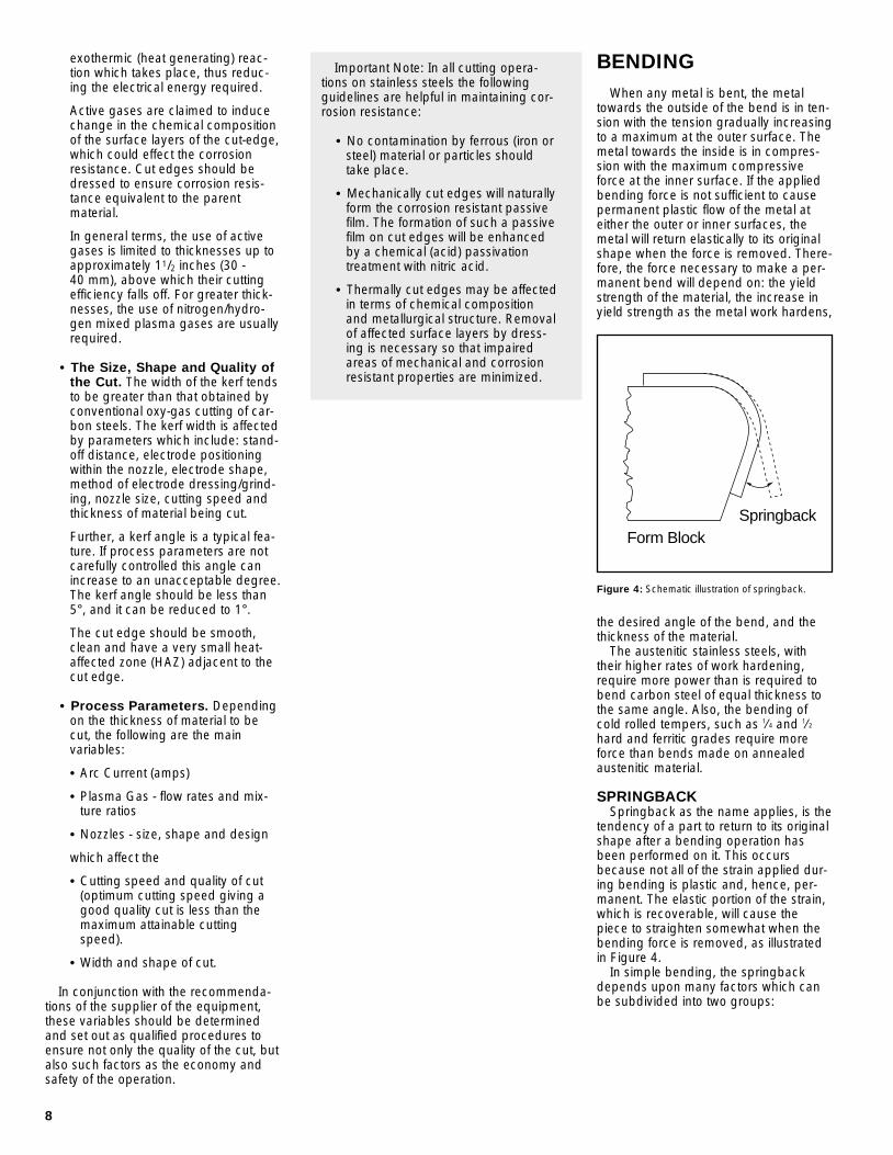
BENDINGWhen any metal is bent, the metal
towards the outside of the bend is in ten-sion with the tension gradually increasingto a maximum at the outer surface. Themetal towards the inside is in compres-sion with the maximum compressiveforce at the inner surface. If the appliedbending force is not sufficient to causepermanent plastic flow of the metal ateither the outer or inner surfaces, themetal will return elastically to its originalshape when the force is removed. There-fore, the force necessary to make a per-manent bend will depend on: the yieldstrength of the material, the increase inyield strength as the metal work hardens,
the desired angle of the bend, and thethickness of the material.
The austenitic stainless steels, withtheir higher rates of work hardening,require more power than is required tobend carbon steel of equal thickness tothe same angle. Also, the bending ofcold rolled tempers, such as 1⁄4 and 1⁄2hard and ferritic grades require moreforce than bends made on annealedaustenitic material.
SPRINGBACKSpringback as the name applies, is the
tendency of a part to return to its originalshape after a bending operation hasbeen performed on it. This occursbecause not all of the strain applied dur-ing bending is plastic and, hence, per-manent. The elastic portion of the strain,which is recoverable, will cause thepiece to straighten somewhat when thebending force is removed, as illustratedin Figure 4.
In simple bending, the springbackdepends upon many factors which canbe subdivided into two groups:
SpringbackForm Block
Figure 4: Schematic illustration of springback.
8
exothermic (heat generating) reac-tion which takes place, thus reduc-ing the electrical energy required.
Active gases are claimed to inducechange in the chemical compositionof the surface layers of the cut-edge,which could effect the corrosionresistance. Cut edges should bedressed to ensure corrosion resis-tance equivalent to the parentmaterial.
In general terms, the use of activegases is limited to thicknesses up toapproximately 11/2 inches (30 - 40 mm), above which their cuttingefficiency falls off. For greater thick-nesses, the use of nitrogen/hydro-gen mixed plasma gases are usuallyrequired.
• The Size, Shape and Quality ofthe Cut. The width of the kerf tendsto be greater than that obtained byconventional oxy-gas cutting of car-bon steels. The kerf width is affectedby parameters which include: stand-off distance, electrode positioningwithin the nozzle, electrode shape,method of electrode dressing/grind-ing, nozzle size, cutting speed andthickness of material being cut.
Further, a kerf angle is a typical fea-ture. If process parameters are notcarefully controlled this angle canincrease to an unacceptable degree.The kerf angle should be less than5°, and it can be reduced to 1°.
The cut edge should be smooth,clean and have a very small heat-affected zone (HAZ) adjacent to thecut edge.
• Process Parameters. Dependingon the thickness of material to becut, the following are the mainvariables:
• Arc Current (amps)
• Plasma Gas - flow rates and mix-ture ratios
• Nozzles - size, shape and design
which affect the
• Cutting speed and quality of cut(optimum cutting speed giving agood quality cut is less than themaximum attainable cuttingspeed).
• Width and shape of cut.
In conjunction with the recommenda-tions of the supplier of the equipment,these variables should be determinedand set out as qualified procedures toensure not only the quality of the cut, butalso such factors as the economy andsafety of the operation.
Important Note: In all cutting opera-tions on stainless steels the followingguidelines are helpful in maintaining cor-rosion resistance:
• No contamination by ferrous (iron orsteel) material or particles shouldtake place.
• Mechanically cut edges will naturallyform the corrosion resistant passivefilm. The formation of such a passivefilm on cut edges will be enhancedby a chemical (acid) passivationtreatment with nitric acid.
• Thermally cut edges may be affectedin terms of chemical compositionand metallurgical structure. Removalof affected surface layers by dress-ing is necessary so that impairedareas of mechanical and corrosionresistant properties are minimized.
3819 Fabrication 6/22/01 2:57 PM Page 12

9
���
����
�1.01
1.02
1.03
1.041.05
1.07
1.10
1.15
1.20
1.30
1.401.50
1.70
2.001 2 3 4 5 6 8 10 12 16 20
Die
Ang
leP
art A
ngle
Par
t Rad
ius
+ T
/2D
ie R
adiu
s +
T/2
or
Die RadiusThickness
a. The geometrical factors, such asthickness, bend radius and bend angleand
b. The characteristics of materials,such as alloy composition and the yieldstrength (before and after bending). Theamount of springback per degree ofbend is constant regardless of the totalangle of the bend. Springback increaseswith increasing ratio of bend radius topart thickness, that is a small bendradius results in less springback than alarge radius on a part of equal thickness.Increasing yield strength also increasesspringback. In addition, the springbackdepends upon the degree to which thepart conforms to the contour of the toolsunder load.
Figure 5: Relationship normally encountered between thickness of material, radius and angle of die and theradius and angle of the part in bending annealed type 300 stainless steels.
ExampleUsing a thickness (T) of 0.100 in. and a die radius of 1.00 in.
Die RadiusT
= 10
ThenDie angle 1.12 Part angle
=(on average)
If part angle is to be 90°, the partmust be bent an average of 100.8°.
If the die angle is to be 90°, the partangle will be an average of 80.3°.
ing pressures that are used for hot rolledcarbon steel four gauges heavier. Coldrolled tempers and the ferritic gradesrequire larger radii than annealedaustenitic material.
On bending a part, the tool strokeshould be as short as possible to lessenthe tendency of stainless steels to foul orscore the tools. To avoid ironing, theclearance between the die and thepunch should be about 10 percent morethan the metal thickness. Dies should begiven a high polish, and must be freefrom all surface blemishes, to preventmarring the finish of the stainlesssteel parts.
Figure 5 shows springback datawhich have been encountered in somecommercial bending operations.
TYPESPress Brakes
Press brake bending of austeniticstainless steels is performed in the sameway as bending of carbon steel withallowances made for the higher strengthand greater springback of stainlesssteels. The power necessary to bendannealed stainless steel is 50 to 60 per-cent more power than is needed for car-bon steel. Cold rolled tempers will needeven more because of their higherstrengths.
Due to their high ductility, theannealed austenitic stainless steels canbe bent to equally small bend radii,gauge for gauge, as carbon steel. How-ever, it is a good rule in setting up brakeforming procedure for one gauge ofstainless steel, to assume the same form-
If the brake forming process involvesprimarily a drawing operation, lubricantsmust be used.
Minimum recommended bend radiivary over rather wide limits. When bend-ing the annealed, more ductile, austeniticgrades, a minimum radius of 1/2 themetal thickness is possible. For hardtempers of austenitic and ferritic gradesradii up to six times the metal thicknessmay be required.
Exhibit 3 shows the minimum bendradii for press brake forming of annealedand cold worked tempers of austeniticstainless steel.
As with carbon steels, V-shapedfemale dies are frequently used. In thiscase the die opening is usually abouteight times the inside radius of theformed part.
Roll BendingThe roll bending of flat stainless steel is
performed in the same manner as withcarbon steel. More power is requiredand there is more springback. Theincreased springback can be offset byincreasing the roll pressure.
The most common types of roll ben-ders are of the pyramid or pinch types.Other types of benders are also used,but in the design of tools one mustremember to compensate for greaterspringback as compared with carbonsteel.
The minimum cylinder which can bemade in stainless steel on a pyramidtype bender is about twice the center rolldiameter as compared to about one anda half times for low carbon steel.
Roll FormingRoll forming is roughly similar to draw-
bench forming, except that it is per-formed with driven rolls, rather thanidling rolls, and is, therefore, a continu-ous process. It is a more economicalmethod of shaping sections in longlengths and large quantities.
Stainless steels can be roll-formedreadily in the annealed state. Extensiveroll forming has been performed suc-cessfully on harder tempers, but morepasses are required.
As with drawbench forming, generallythe same bend radii recommendationsas for other methods of bending shouldbe followed, though bends approachingzero radius have been satisfactorily roll-formed.
High carbon or alloy steels are satis-factory roll materials. Cast aluminumbronze rolls have been used where slid-ing motions between roll and part aregreat.
Dilute solutions of water soluble oilsmake adequate lubricants for roll formingstainless steels. Soap solutions andextreme pressure lubricants give greaterroll protection and produce a finer finishon the stainless steel. They are, however,more difficult to remove.
Exhibit 3MINIMUM BEND RADII FOR PRESS BRAKE FORMING
Annealed SteelsStainless and Low-Carbon Steels 1/2 to 11/2 t
Work-Hardened Stainless Steels1/4 Hard 1 to 2 t1/2 Hard 21/2 to 4 tFull Hard 4 to 6 t
Where t = Metal Thickness
3819 Fabrication 6/22/01 2:57 PM Page 13

DESCALINGREMOVAL OF OXIDE SCALEPickling Solutions
When stainless steel has been heatedto elevated temperatures, such as duringannealing or welding, an oxide scale willform on the surface unless the material iscompletely surrounded by a protectiveatmosphere. Any such oxides should beremoved to restore the stainless steel toits optimum corrosion resistant condition.Because they may vary in nature andcomposition, there is no single acid orprocess that will universally remove alltypes of oxides.
The most common pickling solutionused to remove scale produced byannealing austenitic stainless steel in airis 10 to 15 percent nitric acid plus 1 to 3percent hydrofluoric acid. The solution isusually used at temperatures of 120 to140°F (50 to 60°C). This acid mixture effi-ciently removes oxides, loosely imbed-ded iron and chromium depleted layers,and leaves the stainless steel surface in aclean, passivated condition. For lightscale the hydrofluoric acid is usuallyabout 1 percent and for heavier scalesthe HF content may be increased to 2 to3 percent.
Sulfuric acid 8 to 12 percent with2 percent rock salt (NaCl) at 150 to170°F (65 to 77°C) is well suited forhandling ferritic or martensitic stainlesssteels.
When the oxide scale is heavy andtenacious the stainless steel may betreated for 5 to 10 minutes in a bath of 8to 10 percent sulfuric acid at a tempera-ture of 150 to 160°F (65 to 71°C). Uponremoval from the bath the part should bescrubbed to remove the sludge and afterrinsing, pickling can be finished in anitric-hydrofluoric acid pickling solution.
When the above solutions cannot beused at the recommended temperature,they may be used at room temperaturebut it is usually necessary to strengthenthe acid concentration. A cold solutiontakes longer to act and agitation of thepart can be helpful.
Blasting• Grit blasting — Grit blasting is
generally unsatisfactory becausegrit is seldom clean, and even if itis initially, it soon becomes contami-nated with abraded material. Gritblasting leaves a rough profile thatmakes the stainless steel prone tocrevice corrosion, whether or notthe surface is free of iron. Thus,grit blasting should be avoided.
• Sand blasting — This method isgenerally unsatisfactory. However,for a severely contaminated surface,sand blasting can be used as a lastresort. New, clean sand will removedebris and heavy iron-contaminationfrom the surface. But avoid usingsand blasting, if possible.
• Glass-bead blasting — Goodresults have been obtained withclean, glass beads. Before applyingthis method, a test should be madeto determine that it will remove thesurface contamination. Also, periodi-cally test to see how much reuse ofthe beads can be tolerated beforethey begin to recontaminate thesurface. (Walnut shells have alsoperformed well.)
REMOVAL OF WELD DISCOLORATION
During welding some discoloration,which is a thin oxide layer, will be evidentin the heated area near the weld.Mechanical removal or this heat tintshould be limited to clean glass beadblasting, flapper wheels, aluminum oxidediscs and wire brushing with austeniticstainless steel wire brushes. Sand andgrit blasting should be prohibited. Pick-ling will remove the smeared surfacelayer left by these mechanical cleaningoperatons restoring much of the corro-sion resistance lost during thesemechanical cleaning operations. Electro-cleaning with a hand held electrocleaningtool is an equally effective alternative topickling for heat tint removal.
PASSIVATIONPASSIVATION OF STAINLESSSTEEL
On the surface of stainless steels thereis an extremely thin transparent film.Nevertheless, it is tenacious, uniform,stable and passive. It imparts to the sur-face the property of passivity, normallyassociated with noble or inert metals andit is to this passive film that stainlesssteels owe their superior corrosionresistance.
The film will form spontaneously, orrepair itself if damaged, both in air due tothe presence of oxygen, or whenimmersed in solutions, provided there issufficient oxygen or oxidizing elementspresent. The basic passivation treatmentfor stainless steel is exposure of a cleansurface to air. However, there is muchpractical evidence which shows that pas-sivity, and therefore corrosion resistance,is enhanced if the passive film is formedby the action of oxidizing acid solutions.Nitric acid is such an oxidizing acid, andis always used for passivation treatments.Nitric acid does not corrode stainlesssteel, does not alter critically dimen-sioned parts and will not remove heattint, embedded iron or other embedded
10
Stretch FormingIn free bends the material on the out-
side of the bend is always in tension andthe metal on the inside of the bend is incompression. In stretch forming suffi-cient tension is applied to the materialbeing bent, so that the compressiveforces acting on the inside of the bendmay be counterbalanced and leave thismetal either in a neutral condition or witha small amount of tension. Of course,stretch forming increases the tensionforce on the outside of the bend. How-ever, the high ductility of the annealedaustenitic stainless steels make themwell suited to this method of forming.
Stretch forming finds its greatest usein forming angles, channels, and hollowparts where it is effective in preventingbuckling.
Commonly a tension force 10 to 20percent above the yield strength isapplied to the metal before bending isstarted.
Springback is greatly reduced by thismethod of forming because none of thedeformed metal is under compressiveforce during bending. By proper selec-tion of applied tension, it is sometimespossible to reduce springback to a negli-gible amount.
3819 Fabrication 6/22/01 2:57 PM Page 14

11
surface contamination. Nitric acid passi-vation is most useful in enhancing thecorrosion resistance of freshly machinedsurfaces.
The standard nitric acid passivatingsolution is made up and used as follows:
10 to 15 percent by volume of nitricacid (HNO3) in water. Quickest andbest passivation results if used at150°F (65°C) for the austenitic (300series) stainless steels, and 120°F(50°C) for the ferritic and martensitic(400 series) plain chromium stainlesssteels. The immersion time is approxi-mately 30 minutes, followed bythorough water washing.
It is, however, appreciated that it is notalways possible to fully immerse fabrica-tions in a hot passivating solution, andtherefore, swabbing with cold acid solu-tion is normally used where lower con-centrations and temperatures of acidease handling and application. It mustbe appreciated that longer contact timeswill be required.
For austenitic (300 series)15% nitric acid at 65/80°F (20/25°C).............................30 to 90 minutes
For ferritics (400 series)12% nitric acid at 65/80°F (20/25°C).............................30 to 45 minutes
The acid solution is swabbed on withsponges, soft paint brushes or fine nylonpads. Continual swabbing is necessaryto ensure contact over the time period.For the treatment of small localized areasproprietary passivating pastes areobtainable and can be used. Contacttime should be in accordance with sup-pliers’ recommendations, as the concen-trations may differ from paste to paste,and the lower alloyed grades will requireshorter times. Thorough water rinsingMUST follow all passivating treatments.
CARE IN THE SHOPHANDLING
Mechanical damage (e.g., scratchesand gouges) can occur easily duringhandling if not guarded against. Suchmechanical damage will result in thepassive oxide film being “punctured”leading to a possible lower resistance tothe initiation of corrosion than the sur-rounding chemically passivated surface.In addition, corrosion in such areas canbe accelerated by the galvanic corrosioneffect due to the unfavorable relativearea ratios which exist.
• Plates and sheets should bestored vertically in racks and not bedragged out of the racks or overone another. Racks should be pro-tected to prevent iron contamination.
• Heavy plates should be carefullyseparated and chocked withwooden blocks, in order for theforks of a fork-lift to be insertedbetween plates without mechani-cally damaging the surface. If theforks are haphazardly forced inbetween plates, some degree ofcontamination of the scratches andgouges could also occur, thusaggravating the damage soinduced.
• Plates and sheets laid out for useshould be off the floor and be divided by wooden planks to pre-vent surface damage and facilitatesubsequent handling.
• Plate clamps, if used, must be usedwith care as the serrated faces usu-ally dig in, indent and gouge the surface.
• If chain slings are used, theseinevitably tend to slip, again causingmechanical damage of the surface.Slings of heavy duty synthetic mate-rial are preferable.
• Thin gauge cold rolled materialoften has a superior finish (e.g., pol-ished or bright annealed). Cleanlinen gloves should be worn whenhandling such material to avoid fin-ger markings. Such marks can beremoved by the use of a mildorganic solvent followed by cleaningwith a warm detergent solution.Sometimes a warm detergent willsuffice. Thorough clean water rinsingand drying completes the removalprocedure.
Note: ASTM A380 describes a num-ber of ways fabricating shops canreduce surface contamination dur-ing fabrication.
FINISHINGGRINDING, POLISHING, AND BUFFING
Grinding, polishing, and buffing opera-tions are applied to stainless steel inmuch the same manner as to other metals. The differences which exist arerelated to properties of stainless steel.
1. More power is required to removemetal because of its higherstrength.
2. The austenitic stainless steels havelower rates of heat conductivity thancarbon steel. Thus, the surfacesmay become hotter than the sur-face of carbon steel and heat tintingof the stainless steel surface mayoccur.
Two variables determine the amount ofgrinding and polishing required, namely,the initial surface condition and thedesired finish. The rougher the startingsurface, the coarser is the first grindingwheel. For the first grind on welds, it iscommon practice to use a wheel or abelt with a grit size of 20 to 60. If the arti-cle has a surface equivalent to a 2Bsheet finish, it is often customary to startwith a 100 grit. Succeeding operationsshould make use of increasingly finer gritsize until the desired smoothness isreached. For more information refer tothe SSINA publication “Finishes for Stain-less Steel.”
3819 Fabrication 6/22/01 2:57 PM Page 15

CLEANINGRUST CONTAMINATION
Sometimes the appearance of ruststreaks on stainless steel leads to thebelief that the stainless steel is rusting.Look for the source of the rust in someiron or steel not actually a part of thestainless steel itself. Steel (ferrous) conta-mination is prevented by the use of stain-less steel wire brushes, and grinding withabrasives that have not been used oncarbon steel.
The primary method of cleaning sur-faces contaminated with embedded ironis nitric-HF pickling in 10% nitric 2% HFeither warm or at ambient temperature.Pickling paste is a good alternative toimmersion.
CAUTION: Do not use paint, lacqueror varnish on stainless steel for mainte-nance. It is much safer and easier toclean the metal periodically than to relyon any sort of protective covering.
Exhibit 4EFFECTIVE CLEANING METHODS
Job Cleaning Agents* Comments
Routine Cleaning Warm Water, Soap, Ammonia, Detergent Apply with sponge or cloth.Can be used on all finishes.
Fingerprints and Smears 3M Stainless Steel Cleaner and Polish, Arcal 20, Provides barrier film to minimize fingerprints.Lac-O-Nu, Lumin Wash, O’Cedar Cream Polish, Can be used on all finishes.Stainless Shine
Stubborn Stains and Discoloration 3M Stainless Steel Cleaner and Polish, Allchem Rub lightly, using dry or damp cloth, in the Concentrated Cleaner, Samae, Twinkle, Cameo direction of polish lines on the stainless steel.Copper Cleaner, Grade FFF or Grade F Italian Pumice, Whiting or talc, Liquid Nu Steel, Copper’s or Revere Stainless Steel Cleaner, Household Cleaners, Lumin Cleaner, Zud Restoro, Sta-Clean, Highlite, Allen Polish, Penny-Brite, Copper-Brite
Grease and Blood, Scotch-Brite Power Pad 2001, Easy-Off, De-Grease-It, Excellent removal on acids, all finishes. Burnt-on or Baked-on Foods 4% to 6% hot solution of such agents as tri-sodium Particularly useful where rubbing is not practical.
polyphosphate, 5% to 15% caustic soda solution
Grease and Oil Any good commercial detergent or caustic cleanser. Apply with sponge or cloth in direction of polish lines.
*NOTE: Use of proprietary names is intended only to indicate a type of cleaner and does not constitute an endorsement. Omission of any proprietary cleanser does not imply itsinadequacy. All products should be used in strict accordance with instructions on package.
12
CLEANING METHODSSoap or detergent and water will
remove ordinary deposits of grease, dirtand similar contaminations. Washingshould be followed with a water rinseand thorough drying.
Tightly adhering deposits of food, oil,grease, milkstone, atmospheric stainsand other light discolorations may beremoved with the appropriate commer-cial cleaners shown in Exhibit 4.
For high luster finishes soft clothes orpads must be used without contamina-tion from foreign dirt or grit (even fromwater employed to dampen) in order toavoid scratching highly reflective surfaces.
For additional information refer to theNiDI publication No. 9001 “Cleaning andDescaling Stainless Steels.” or the SSINADesigner Handbook “The Care andCleaning of Stainless Steel.”
CONTAMINATIONContamination arises mainly from the
surfaces of equipment which have previ-ously been used in contact with carbon(mild) steel. The carbon steel and oxidescale may be smeared on and trans-ferred to the stainless steel surface. Whileit is not always possible to have handlingequipment dedicated for use with stain-less steel, this should be done if possible(e.g., synthetic material slings).
All other handling equipment shouldbe cleaned prior to use with stainlesssteel. It is, therefore, advisable to planand schedule the handling of stainlesssteel, because if handling equipment isused on a random basis, this cleaningis often neglected and contaminationresults.
3819 Fabrication 6/22/01 2:57 PM Page 16