ssd/raid reconfiguration procedures for … regarding battery backup is displayed, acknowledge the...
TRANSCRIPT

Contents
IntroductionPrerequisiteHardware RequirementsProceduresStep 1: Backup the Current Configuration and DataStep 2. Remove and Replace the Existing Storage MediaStep 3. Reconfigure the RAID ControllerStep 4. Reconfigure the Flash Storage HardwareStep 5. Reinstall the operating systemStep 6. Restore the backupRelated Cisco Support Community Discussions
Introduction
The Cisco Unified Computing System (UCS) devices are configured with RAID hardware andassociated drives to configure a logical volume, which provides redundancy and presents the OSwith a single storage space. This document describes the steps to:
Back up the existing Sourcefire software installation●
Remove and replace the existing storage media●
Reconfigure the RAID controller●
Reconfigure the storage hardware●
Re-install the operating system●
Restore the backup●
Prerequisite
Hardware Requirements
The instruction in this document is applicable on Cisco FireSIGHT Management Center FS2000and FS4000 models.
This document is created using the devices that are in a specific lab environment. All of thedevices used in this document started with a cleared (default) configuration. If your network is live,make sure that you understand the potential impact of any command.
Procedures
Step 1: Backup the Current Configuration and Data
1.1. Login to the web user interface (also known as GUI) for the UM.

1.2. Navigate to System > Tools > Backup/Restore.
1.3. Click Defense Center Backup. The Backup Management page appears.
1.4 Give the backup a name in the Name field.
1.5 Make sure the Back Up Configuration and the Back Up Events are selected.
1.6 Click the Start Backup button.
Tip: The backup archive is a tar.gz file located in /var/sf/backups
Step 2. Remove and Replace the Existing Storage Media
Note: If you have received replacement drives already installed in drive sleds, this procedureis not necessary: just use the sleds that came with the drives
2.1. Halt the system and power down.
2.2. Systems should be configured with 6 drives configured in two rows. One by one depress therelease catch and rotate the handle outward to remove the drive.

2.3. Unscrew the drives from the drive sleds. There are four screws to remove, which are securedwith thread adhesive. The screws may be somewhat difficult to remove.
Figure: Four Phillips head screws secure the drive to the sled: two on each side.
Note: Replacing the SSDs is the reverse of the operation above. SSDs are generally around¼ thick, and will rest in the bottom of the sled.
2.5. Make sure the drive is face up in the sled and the power and data connections are facing therear of the sled, opposite the locking lever. The locking lever has a hook that catches onto thechassis and pulls the drive into the system securely connecting it to the backplane. The drivecannot be seated completely if the latch hook is not fully engaged before closing the lever.
Step 3. Reconfigure the RAID Controller
3.1. Power the system up and wait for the RAID BIOS to display a message indicating to pressCtrl+H to display the WebBIOS. This is the configuration screen for the RAID controller. Oncethe system is done with POST and Ctrl+H has been pressed, the following screen is displayed:
3.2. Click Start to begin RAID configuration.
3.3. Here you can see the current RAID configuration:

3.4. This system is up and running with a healthy RAID. If the original drives have already beenreplaced, the virtual drive will be missing and the drives will show as unconfigured. In this case theexisting configuration will be removed and reconfigured. In either case, click ConfigurationWizard to begin the process.
3.5. Select New Configuration and click Next.
3.6. If prompted, choose Yes to clear the current configuration:
3.7. Select Manual Configuration and click Next:
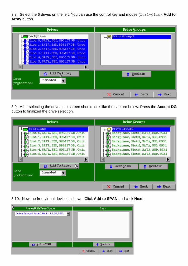
3.8. Select the 6 drives on the left. You can use the control key and mouse (Ctrl+Click Add toArray button.
3.9. After selecting the drives the screen should look like the capture below. Press the Accept DGbutton to finalized the drive selection.
3.10. Now the free virtual device is shown. Click Add to SPAN and click Next.

3.11. The next screen is where the RAID specific settings are configured.
Note: In the right hand window, the text Next LD: Possible RAID levels displays thesize needed for each RAID level. RAID 6 is the desired configuration, and the size displayedis 3.4888 TB. This size needs to be entered into the Select Size field as shown below.
3.12. All other settings on the screen show above should be left unchanged. Press Accept. Amessage regarding battery backup is displayed, acknowledge the message to continue. When thevirtual drive is listed as shown below, press Next, click Accept, then click Yes to the questionSave this Configuration.

3.13. A warning message appears to indicate that all of the data will be lost on the drives, clickYes.
3.14. The RAID process is complete, click the door icon on the tool bar to exit and press Yes.
3.15. You must reboot to complete the process.
Step 4. Reconfigure the Flash Storage Hardware
Note: The UCS systems have an internal USB flash drive that is used by the Firepowerinstallation as the System Restore partition. This device sometimes becomes 'disconnected'from the system and may not be detected by the Firepower installation.
Note: The following process requires SSH access to the Cisco Integrated ManagementController (CIMC). CIMC configuration is beyond the scope of this document.
4.1. Access the CIMC through Secure Shell (SSH) and log in with the admin account. Use the IPAddress of the CIMC when you want to access.
localhost:~$ ssh [email protected]
[email protected]'s password:
CIMC#
4.2. Change to the chassis scope:
CIMC# scope chassis
CIMC/chassis#
4.3. Check the status of the flexflash controller:
CIMC/chassis# show flexflash
Controller Product Name Has Error Firmware Version Vendor Internal State ------------ ----------
------ ---------- ----------------- -------- --------------- FlexFlash-0 Cisco FlexFlash No 1.2
build 258 Cypress Connected
In this example, the flexflash state shows as Connected. If it shows Disconnected, use thefollowing command to reset the flexflash partition.
4.4. Change to the flexflash scope and run the reset command:
CIMC/chassis# scope flexflash FlexFlash-0
CIMC/chassis/flexflash# reset-partition-defaults SLOT-1
This action will mark the SLOT-1 as healthy primary slot and SLOT-2 (if card existing) as
unhealthy secondary-active. This operation may disturb the host connectivity as well.
Continue?[y|N] y
Check the status again to ensure that the flexflash state is now showing as Connected. The

unit is now ready to reinstall the operating system.
Step 5. Reinstall the operating system
To reinstall the system, navigate to the CIMC interface. This interface is used to:
Map an ISO image to a drive on the system●
Reboot the system using the ISO image●
Interact with the installer●
5.1. Acquire the ISO installation media for the release of your choice and make sure it isaccessible from the system on which you are running the CIMC web interface.
5.2. Navigate to the CIMC IP address to access the interface using a web browser:
5.3. Click the KVM console icon.
Note: You will need to have java set up correctly on the client operating system and browserto work with KVM properly.
5.4. There will be several warning boxes that pop up in succession warning about using java, thatyou are downloading an application etc. Respond affirmatively to each prompt to continue.
5.6. You will see the virtual KVM console window. At the top on the menu bar click the VirtualMedia menu, and select Activate Virtual Devices.

5.7. Now click Map CD/DVD. A file browser window appears. Navigate to the location of the ISOinstallation media and select the ISO. If you do not see the Map CD/DVD option, make sure youselected Activate Virtual Devices in the previous step.
Note: The mapping option is not be visible until activated.
5.8. Next click Map Device.
5.9. Now on the Power menu, select Reset System (Warm boot).
5.10. Once the Cisco splash logo appears start pressing <F6> to get the system Boot Menu.Press <F6> once in every few seconds until you see Entering boot selection menu… likebelow:
5.11. Once you see the boot menu, select the item labeled Cisco vKVM-Mapped vDVD1.22and press enter. The system now boots up from the ISO installation media.

The installation is simple from here, you will be asked 3 questions:
If you are sure you want to install●
If you want to delete network and license settings●
Are you sure you want to wipe the system and install●
If you have reconfigured your drives, there is nothing to save as far as license and networksettings, so answering yes to all 3 questions is fine.
Step 6. Restore the backup
Configure the network settings on your appliance as you normally would for your environment.
6.1. Navigate to System > Tools > Backup/Restore.
6.2. Select Upload Backup.
Note: Your backup file must be available to the system from which you are using the webuser interface.
6.3. Browse to the backup archive and select it.
6.4. Select the Upload Backup button. Once uploaded, the backup should be available in theDefense Center Backups list.
6.5. Select the check box and click Restore.
Note: Be sure to check both Events and Configuration if that you wish to restore both.