ssd1963 eval rev2a user’s guide - techtoys.com.hk€¦ · ssd1963 eval rev2a user’s guide...
TRANSCRIPT
User’s Guide of SSD1963 Eval Rev2A
Doc. version 1.0b 8th Feb 2010 Page 1
SSD1963 Eval Rev2A
User’s Guide
TechToys Company
Unit 1807, Pacific Plaza, 410 Des Voeux Road
West, Hong Kong
Tel: 852-28576267
Fax: 852-28576216
Web site: www.TechToys.com.hk
User’s Guide of SSD1963 Eval Rev2A
Doc. version 1.0b 8th Feb 2010 Page 2
1. Introduction
SSD1963 Eval Rev2A is a development board for Solomon SSD1963 display
controller which provides 1,215K byte frame buffer with parallel MCU interfaces
for RAM-less LCD panels up to 864x480 at 24-bit per pixel resolution. With linear
voltage regulators, LED backlight circuits, and FPC connectors for touch panels
all built-in, users are provided with all necessary circuitry for testing TFT panels
of different size with their own choice of host microcontrollers.
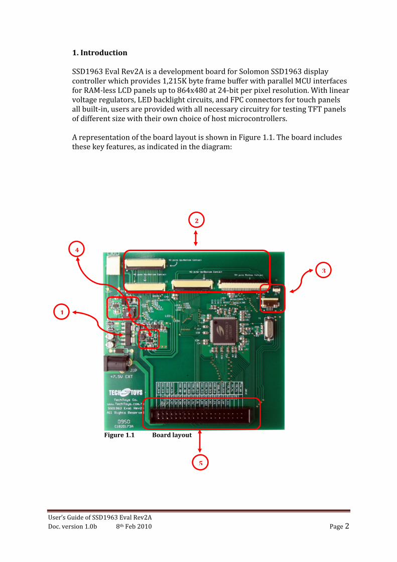
A representation of the board layout is shown in Figure 1.1. The board includes
these key features, as indicated in the diagram:
1
2
3
4
5
Figure 1.1 Board layout
User’s Guide of SSD1963 Eval Rev2A
Doc. version 1.0b 8th Feb 2010 Page 3
1. Voltage regulators for 5V, 3.3V, and 1.2V driving LED backlight (5V), interface
supply power for LCD and digital I/O (3.3V), as well as the core supply
voltage (1.2V) for SSD1963.
2. Four FPC connectors (J1~J4) for different LCD panels. There are dozens of
TFT pin-out definitions as there is no industrial standard for this. Only four
connectors will not cover all of the TFT interfaces but at least four panel sizes
have been verified including 3.5”, 4.3”, 5.6”, and 7” TFT panels on this
evaluation board.
3. Two FPC connectors (J5, J6) of bottom contact for touch panels. Some panels
have individual FPC for Touch Panel while others have Touch Panel signal
integrated with data bus on a single FPC. These FPC connectors of 0.5mm and
1.00mm pitch provide a convenient access to Touch Panel signals in case the
signals are separated from the data-bus-FPC. This is very common for large
panel size like 5.6” and 7” panels.
4. Two LED backlight circuits for
a. High voltage 20mA constant current white LED driver (CAT4237, On
Semiconductor Inc). The CAT4237 is a DC/DC step-up converter that
delivers an accurate constant current source driving 6 to 8 white LEDs
in series. Output of CAT4237 is routed to J3 and J4 for 4.3” and 3.5”
panels, respectively.
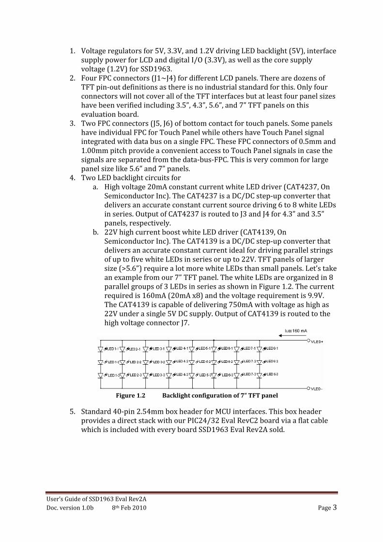
b. 22V high current boost white LED driver (CAT4139, On
Semiconductor Inc). The CAT4139 is a DC/DC step-up converter that
delivers an accurate constant current ideal for driving parallel strings
of up to five white LEDs in series or up to 22V. TFT panels of larger
size (>5.6”) require a lot more white LEDs than small panels. Let’s take
an example from our 7” TFT panel. The white LEDs are organized in 8
parallel groups of 3 LEDs in series as shown in Figure 1.2. The current
required is 160mA (20mA x8) and the voltage requirement is 9.9V.
The CAT4139 is capable of delivering 750mA with voltage as high as
22V under a single 5V DC supply. Output of CAT4139 is routed to the
high voltage connector J7.
Figure 1.2 Backlight configuration of 7” TFT panel
5. Standard 40-pin 2.54mm box header for MCU interfaces. This box header
provides a direct stack with our PIC24/32 Eval RevC2 board via a flat cable
which is included with every board SSD1963 Eval Rev2A sold.
User’s Guide of SSD1963 Eval Rev2A
Doc. version 1.0b 8th Feb 2010 Page 4
2. Hardware
Hardware used in this manual includes the following components
1. Evaluation board for Microchip 100-Pin General Purpose MCU:
Option with PIC32MX360F512L
Part number: PIC24/32 EVAL Rev2A – option PIC32MX360F512L
2. Evaluation kit for Solomon SSD1963 Display Controller
Part number: SSD1963 Eval Rev 2A
3. 3.5" QVGA color TFT-LCD module with Touch Panel
Part number: LVC75Z779V1S
4. 4.3" WQVGA color TFT-LCD module with Touch Panel
Part number: TY430TFT480272Rev03
5. 7" WVGA 262k color TFT-LCD module with Touch Panel
Part number: TY700TFT800480Rev01
3. Software
Several demo programs are provided for quality assurance. These programs
have been developed under Microchip Graphics Library Version v2.00 with a low
level driver for SSD1963 developed by us.
However, I must emphasize that, it is not restricted to use Microchip’s
microcontrollers to interface the SSD1963. Any microcontroller or processor
that is able to generate the required control signal (CS#, DC, RD#, WR#, and
D[23:0]) will be able to drive SSD1963. There are few Graphical Libraries such as:
• Luminary (now belongs to Texas Instruments) Micro Graphics Library o http://www.luminarymicro.com/products/stellaris_graphics_library.html
• Renesas Graphics Library o http://america.renesas.com/fmwk.jsp?cnt=sw_lib_child.htm&fp=/products
/mpumcu/h8_family/h8_lcd/child_folder/&title=Graphic%20Animation%2
0Software
• PEG embedded Graphical User Interface o http://swellsoftware.com/products/
• Easy GUI by IBIS Solution ApS o http://www.easygui.com
• emWin supplied by Segger Microcontroller GmbH & Co. KG o www.segger.com
Some of these libraries are free as long as you would use their products while the
others provide port to various MCUs at a certain cost. Users may select their host
and decide which GUI is the best for the application. Microchip Graphics Library
has been chosen because it is free as long as the library will be embedded in
Microchip products.
User’s Guide of SSD1963 Eval Rev2A
Doc. version 1.0b 8th Feb 2010 Page 5
4. Installing different LCD Panels
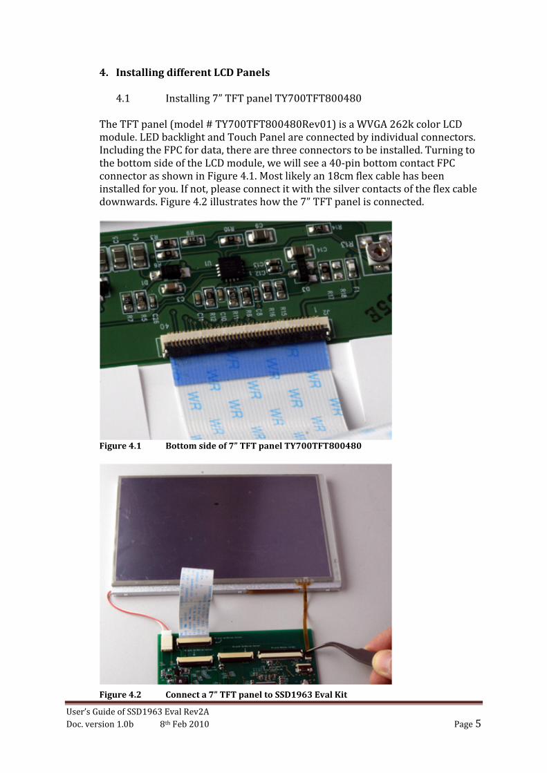
4.1 Installing 7” TFT panel TY700TFT800480
The TFT panel (model # TY700TFT800480Rev01) is a WVGA 262k color LCD
module. LED backlight and Touch Panel are connected by individual connectors.
Including the FPC for data, there are three connectors to be installed. Turning to
the bottom side of the LCD module, we will see a 40-pin bottom contact FPC
connector as shown in Figure 4.1. Most likely an 18cm flex cable has been
installed for you. If not, please connect it with the silver contacts of the flex cable
downwards. Figure 4.2 illustrates how the 7” TFT panel is connected.
Figure 4.1 Bottom side of 7” TFT panel TY700TFT800480
Figure 4.2 Connect a 7” TFT panel to SSD1963 Eval Kit

User’s Guide of SSD1963 Eval Rev2A
Doc. version 1.0b 8th Feb 2010 Page 6
Important message: There are three 40-pin FPC connectors onboard. They are J1,
J2, and J3. They come from the same manufacturer of the same model but they
have been designed to connect different TFT panels. Don’t confuse them;
otherwise, your TFT panel may be damaged.
Connect the 18cm flex cable of TY700TFT800480 to only J1! This time, silver
contacts of the flex cable should be facing upwards. Then, J7 connection can be
made for backlight. Connector J7 is a high voltage connector which is wired to
CAT4139 for a driving current as high as 160mA. Figure 4.3 illustrates the
connections.
Finally, connect the FPC for Touch Panel to J5 as shown in Figure 4.4. Use a
tweezers to handle this part close to the tip (don’t clip on the soft cable part.)
Push gently the FPC into J5 with gold contacts down. Please do it slowly with
great care because this FPC is very fragile.
Figure 4.3 Connection of J1 and J7 for 7” TFT panel (TY700TFT800480)
Figure 4.4 Connect Touch Panel FPC to J5 by holding the tip of the FPC
User’s Guide of SSD1963 Eval Rev2A
Doc. version 1.0b 8th Feb 2010 Page 7
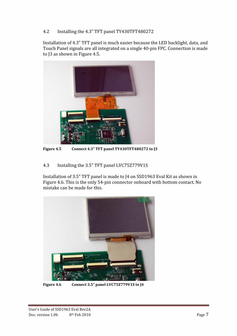
4.2 Installing the 4.3” TFT panel TY430TFT480272
Installation of 4.3” TFT panel is much easier because the LED backlight, data, and
Touch Panel signals are all integrated on a single 40-pin FPC. Connection is made
to J3 as shown in Figure 4.5.
Figure 4.5 Connect 4.3” TFT panel TY430TFT480272 to J3
4.3 Installing the 3.5” TFT panel LVC75Z779V1S
Installation of 3.5” TFT panel is made to J4 on SSD1963 Eval Kit as shown in
Figure 4.6. This is the only 54-pin connector onboard with bottom contact. No
mistake can be made for this.
Figure 4.6 Connect 3.5” panel LVC75Z779V1S to J4
User’s Guide of SSD1963 Eval Rev2A
Doc. version 1.0b 8th Feb 2010 Page 8
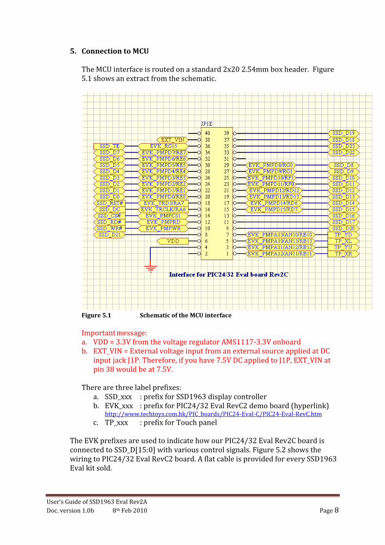
5. Connection to MCU
The MCU interface is routed on a standard 2x20 2.54mm box header. Figure
5.1 shows an extract from the schematic.
Figure 5.1 Schematic of the MCU interface
Important message:
a. VDD = 3.3V from the voltage regulator AMS1117-3.3V onboard
b. EXT_VIN = External voltage input from an external source applied at DC
input jack J1P. Therefore, if you have 7.5V DC applied to J1P, EXT_VIN at
pin 38 would be at 7.5V.
There are three label prefixes:
a. SSD_xxx : prefix for SSD1963 display controller
b. EVK_xxx : prefix for PIC24/32 Eval RevC2 demo board (hyperlink) http://www.techtoys.com.hk/PIC_boards/PIC24-Eval-C/PIC24-Eval-RevC.htm
c. TP_xxx : prefix for Touch panel
The EVK prefixes are used to indicate how our PIC24/32 Eval Rev2C board is
connected to SSD_D[15:0] with various control signals. Figure 5.2 shows the
wiring to PIC24/32 Eval RevC2 board. A flat cable is provided for every SSD1963
Eval kit sold.
User’s Guide of SSD1963 Eval Rev2A
Doc. version 1.0b 8th Feb 2010 Page 9
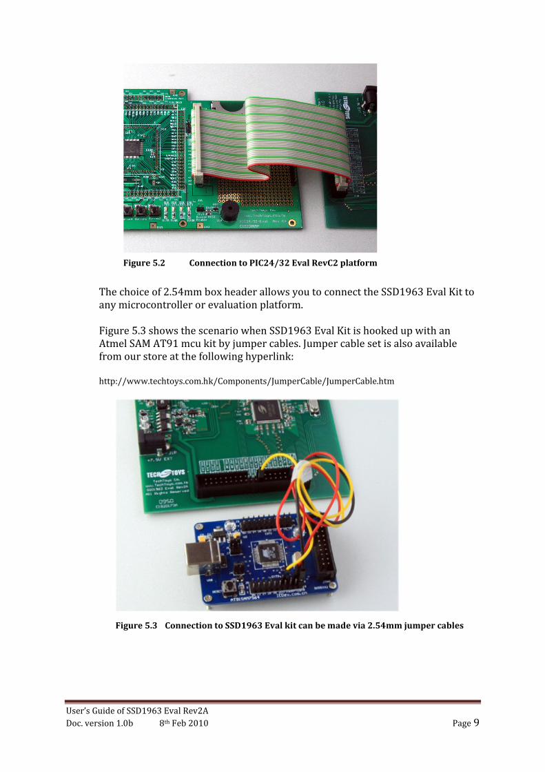
The choice of 2.54mm box header allows you to connect the SSD1963 Eval Kit to
any microcontroller or evaluation platform.
Figure 5.3 shows the scenario when SSD1963 Eval Kit is hooked up with an
Atmel SAM AT91 mcu kit by jumper cables. Jumper cable set is also available
from our store at the following hyperlink:
http://www.techtoys.com.hk/Components/JumperCable/JumperCable.htm
Figure 5.3 Connection to SSD1963 Eval kit can be made via 2.54mm jumper cables
Figure 5.2 Connection to PIC24/32 Eval RevC2 platform
User’s Guide of SSD1963 Eval Rev2A
Doc. version 1.0b 8th Feb 2010 Page 10
6. Installing the hardware
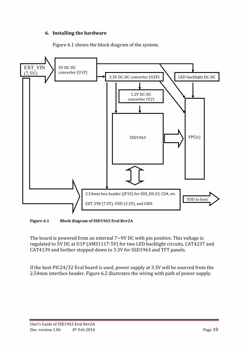
Figure 6.1 shows the block diagram of the system.
Figure 6.1 Block diagram of SSD1963 Eval Rev2A
The board is powered from an external 7~9V DC with pin positive. This voltage is
regulated to 5V DC at U1P (AMS1117-5V) for two LED backlight circuits, CAT4237 and
CAT4139 and further stepped down to 3.3V for SSD1963 and TFT panels.
If the host PIC24/32 Eval board is used, power supply at 3.3V will be sourced from the
2.54mm interface header. Figure 6.2 illustrates the wiring with path of power supply.
5V DC-DC
converter (U1P) 3.3V DC-DC converter (U2P)
1.2V DC-DC
converter (U2)
SSD1963
2.54mm box header (JP1E) for SSD_D0:23, CS#, etc
EXT_VIN (7.5V), VDD (3.3V), and GND
FPC(s)
LED backlight DC-DC
EXT_VIN
(7.5V)
VDD to host
User’s Guide of SSD1963 Eval Rev2A
Doc. version 1.0b 8th Feb 2010 Page 11
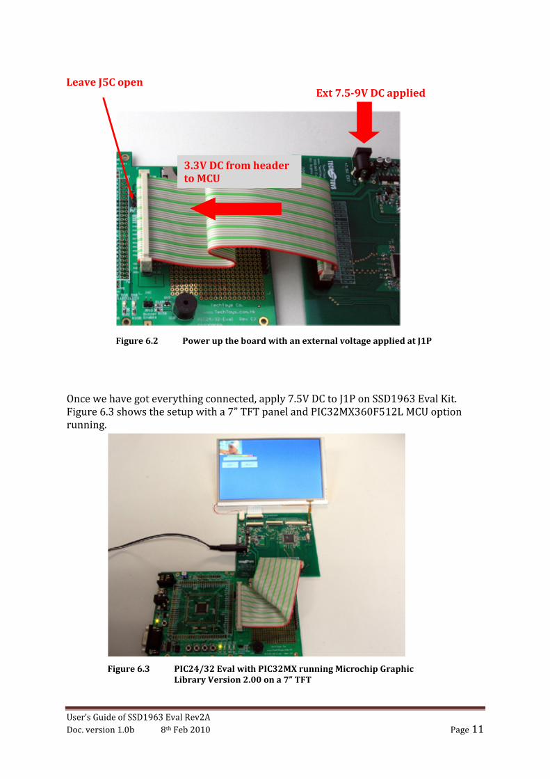
Once we have got everything connected, apply 7.5V DC to J1P on SSD1963 Eval Kit.
Figure 6.3 shows the setup with a 7” TFT panel and PIC32MX360F512L MCU option
running.
Ext 7.5-9V DC applied Leave J5C open
Figure 6.2 Power up the board with an external voltage applied at J1P
Figure 6.3 PIC24/32 Eval with PIC32MX running Microchip Graphic
Library Version 2.00 on a 7” TFT
3.3V DC from header
to MCU

User’s Guide of SSD1963 Eval Rev2A
Doc. version 1.0b 8th Feb 2010 Page 12
7. Running the Program
7.1 Starting the Demo Project
At time of writing, six projects are provided for out-of-the-box
demonstration. These demos have been modified from the original demos
provided by Microchip Graphics Library v2.001.
Development Environment:
• Microchip MPLAB version 8.10 or later
• C32 compiler version 1.05 or later
• Microchip Graphics Library version 2.00
The source code is available for download starting from Doc 04 under our
product web site at this hyperlink.
http://www.techtoys.com.hk/Displays/SSD1963EvalRev2A/SSD1963 Eval Board Rev2A.htm
1 http://www.microchip.com/stellent/idcplg?IdcService=SS_GET_PAGE&nodeId=2608¶m=en532067
Figure 7.1 Projects based on Microchip Graphics Library v2.00
User’s Guide of SSD1963 Eval Rev2A
Doc. version 1.0b 8th Feb 2010 Page 13
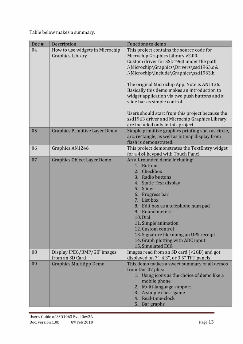
Table below makes a summary:
Doc # Description Functions to demo
04 How to use widgets in Microchip
Graphics Library
This project contains the source code for
Microchip Graphics Library v2.00.
Custom driver for SSD1963 under the path
.\Microchip\Graphics\Drivers\ssd1963.c &
.\Microchip\Include\Graphics\ssd1963.h
The original Microchip App. Note is AN1136.
Basically this demo makes an introduction to
widget application via two push buttons and a
slide bar as simple control.
Users should start from this project because the
ssd1963 driver and Microchip Graphics Library
are included only in this project.
05 Graphics Primitive Layer Demo Simple primitive graphics printing such as circle,
arc, rectangle, as well as bitmap display from
flash is demonstrated.
06 Graphics AN1246 This project demonstrates the TextEntry widget
for a 4x4 keypad with Touch Panel.
07 Graphics Object Layer Demo An all-rounded demo including:
1. Buttons
2. Checkbox
3. Radio buttons
4. Static Text display
5. Slider
6. Progress bar
7. List box
8. Edit box as a telephone num pad
9. Round meters
10. Dial
11. Simple animation
12. Custom control
13. Signature like doing an UPS receipt
14. Graph plotting with ADC input
15. Simulated ECG
08 Display JPEG/BMP/GIF images
from an SD Card
Images read from an SD card (<2GB) and got
displayed on 7”, 4.3”, or 3.5” TFT panels!
09 Graphics MultiApp Demo This demo makes a sweet summary of all demos
from Doc 07 plus:
1. Using icons as the choice of demo like a
mobile phone
2. Multi-language support
3. A simple chess game
4. Real-time-clock
5. Bar graphs
User’s Guide of SSD1963 Eval Rev2A
Doc. version 1.0b 8th Feb 2010 Page 14
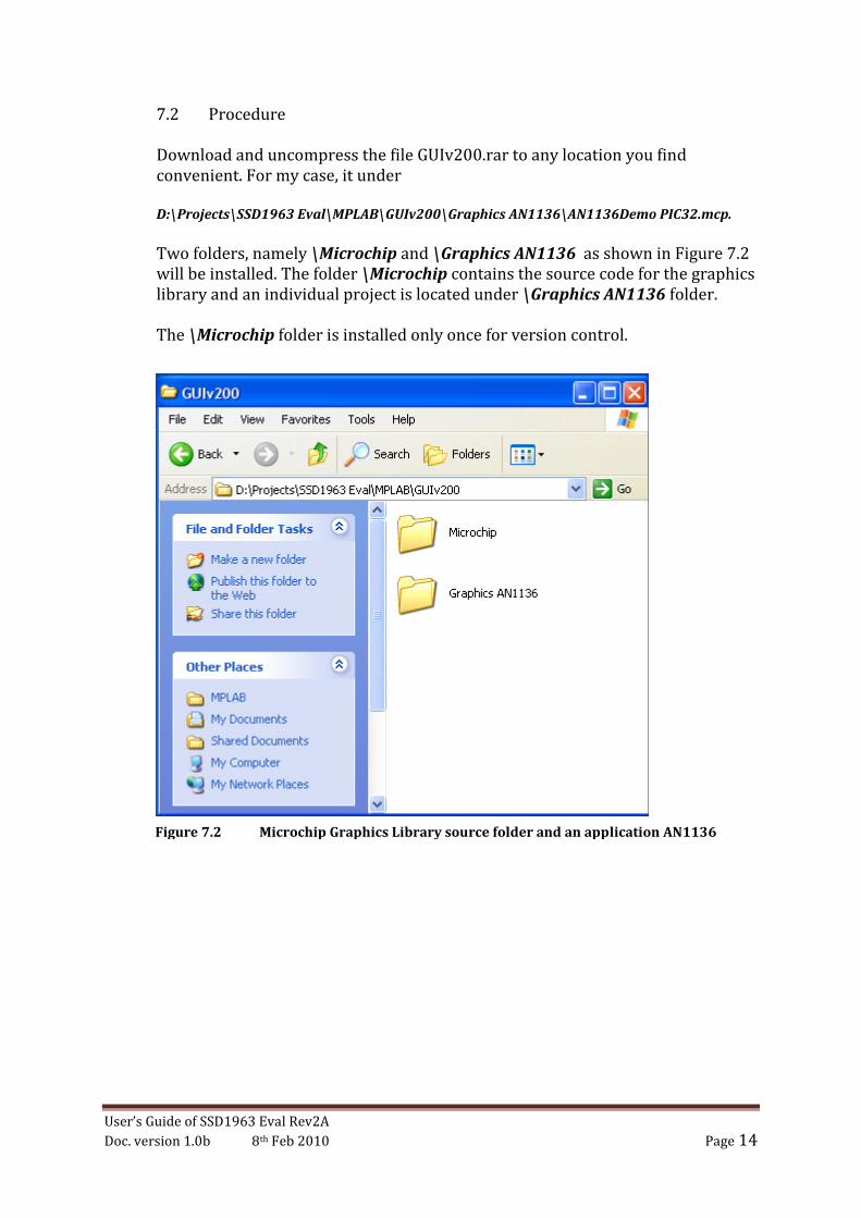
7.2 Procedure
Download and uncompress the file GUIv200.rar to any location you find
convenient. For my case, it under
D:\Projects\SSD1963 Eval\MPLAB\GUIv200\Graphics AN1136\AN1136Demo PIC32.mcp.
Two folders, namely \Microchip and \Graphics AN1136 as shown in Figure 7.2
will be installed. The folder \Microchip contains the source code for the graphics
library and an individual project is located under \Graphics AN1136 folder.
The \Microchip folder is installed only once for version control.
Figure 7.2 Microchip Graphics Library source folder and an application AN1136
User’s Guide of SSD1963 Eval Rev2A
Doc. version 1.0b 8th Feb 2010 Page 15
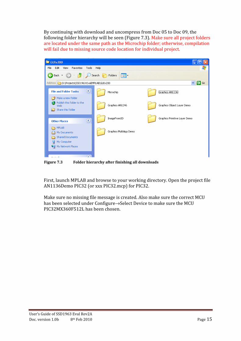
By continuing with download and uncompress from Doc 05 to Doc 09, the
following folder hierarchy will be seen (Figure 7.3). Make sure all project folders
are located under the same path as the Microchip folder; otherwise, compilation
will fail due to missing source code location for individual project.
First, launch MPLAB and browse to your working directory. Open the project file
AN1136Demo PIC32 (or xxx PIC32.mcp) for PIC32.
Make sure no missing file message is created. Also make sure the correct MCU
has been selected under Configure→Select Device to make sure the MCU
PIC32MX360F512L has been chosen.
Figure 7.3 Folder hierarchy after finishing all downloads
User’s Guide of SSD1963 Eval Rev2A
Doc. version 1.0b 8th Feb 2010 Page 16
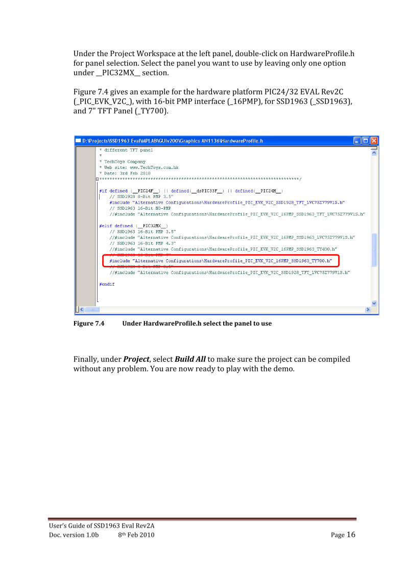
Under the Project Workspace at the left panel, double-click on HardwareProfile.h
for panel selection. Select the panel you want to use by leaving only one option
under __PIC32MX__ section.
Figure 7.4 gives an example for the hardware platform PIC24/32 EVAL Rev2C
(_PIC_EVK_V2C_), with 16-bit PMP interface (_16PMP), for SSD1963 (_SSD1963),
and 7” TFT Panel (_TY700).
Un
Finally, under Project, select Build All to make sure the project can be compiled
without any problem. You are now ready to play with the demo.
Figure 7.4 Under HardwareProfile.h select the panel to use