ssc-356 fatigue performance under multiaxial loading · · 2006-05-18fatigue performance under...
TRANSCRIPT
SSC-356
FATIGUE PERFORMANCE
UNDER MULTIAXIAL LOADING
Thisdmmtenthasbeenapprovedforpublicreleasesndsale;itsCListrilnltionisunlimited
SHIP STRUCTURE COMMITTEE
1990

SHIP STRUC URF COMMlllEET
The SHIP STRUCTURE COMMlll_EE is constituted to prosecute a research program to improve the hullstructures of ships and other marine structures by an extension of knowledge pertakring to design,materials, and methods of construction,
RADM J. D. Sip=, USCG, (Chairman)Chief, Office of Marine Safety, Semrity
and Environmental ProtectionU. S. Coast Guard
Mr. Alexander MalakhoffDirector, Structural Integrity
Subgroup (S= 55Y)Naval Sea Systems Command
Dr. Donald LiuSenior Vice PresidentAmerican Bureau of Shipping
Mr. H. T. Hailer&.sociate Administrator for Ship-
building and Ship OwrationsMaritime Administration
Mr. Thomas W. AllenEngineering Ofricer (N7)Military Sealifl Command
CDR Michael K. Parmelee, uSCG,Secretary, Ship Structure CommitteeU.S. Coast Guard
CONTRACT ING OFFICFR TFCHNICAL RE PRESFNTATIVFS
Mr. William J. Siekierka Mr. Greg D. WoodsSEA55Y3 SEA55Y3Naval Sea Systems Command Naval Sea Systems Command
SHIP STRUCTURF SUBCOMMll_FF
The SHIP STRUCTURE SUBCOMMlmEE acts for the Ship Structure Committee on technical matters byproviding technical coordination for determinating the goals and objectives of the program and byevaluating and interpreting the results in terms of structural design, construction, and operation.
AMERICAN BUREAU OF SHIPPING
Mr. Stephen G. Arntson (Chairman)Mr, John F. ConIonMr. William HanzalekMr, Philip G. Rynn
MILITARY SFAI In COMMA DN
Mr. Albert J, AttermeyerMr. Michael W. ToumaMr. Jeffery E. Beach
NAVAL SEA SYSTEMS COMMAND
Mr. Rokrf A SielskiMr. Charles L. NullMr. W, Thomas PackardMr. Allen H. Engle
U.S. CtTAST G( IARD
CAPT T. E. ThompsonCAPT Donald S. JensenCDR Mark E. Nell
MARITIME ADMINISTRATION
Mr. Frederick SeiboldMr. Norman O. HammerMr. Chao H, LinDr. Walter M. Maclean
SHIP STRU~COT MMllTFF I IAISON MEMRFRS
U. S. COAST ‘W ARD ACADFMY
LT Bruce Mustain
U. S. MERCHANT MARINE ACADEMY
Dr. C. B, Kim
U, S. NAVAL ACADEMY
Dr. Ramswar Bhattacharyya
~MARITIME COLLEGEF
Dr. W. R. Porter
WELDING RESEARCH COUNCIL
Dr. Martin Prager
NA 10 AI AC~FMY OF SCIFNCFS —M~Rl~EBOARD
Mr. Alexander B. Stavovy
NATIONAL ACADEMY OF SCIENCES -OMMHTFF ON MARINE STRU CTURES
Mr. Stanley G. Stiansen
SOCIETY OF NAVA~::CHITECTS ANDM~RINE ENGINEE
r-lMMWTEF
Dr. William Sandberg
AMERICAN IRON AND STEEL INSTITUTE
Mr. Alexander D. Wilson
Member Agtincies:
United States Coast GuardNaval SeaSystems Command
Maritime AdministrationAmerican Bureau of Sh@ping
Military SeadhY Command
& Address Corres~ndence to:
Secretay, Ship Structure Committee
ShipU.S. Coast Guard (G-MTH)2100 Second Street S,W.
Structure Washington, D.C. 20593-0001PH: (202) 267-0003
Committee FAX:(202) 267-0025
AnInteragencyAdvisoryCommitteeDedicatedtotheImprovementofMarineStructures
SSC-356December 3, 1990 SR-1323
FATIGUE PERFORMANCE UNDER MULTIAXIAL LOADING
We clearly recognize the need to consider fatigue in the designof marine structures. The analysis of complicated geometries canbe difficult where variable multiaxial loads are applied.Fatigue testing of large fabricated details is very costly. Thisreport provides a review and summary of methodologies used topredict the fatigue performance of structural details undermultiaxial loading conditions. This investigation should providea basis for further research leading to increased reliability ofmarine structures.
BRear Admiral, U.S. Coast Guard
Chairman, Ship Structure Committee

Technical kspw?DocumentationPogc
SSC- 356
4. Titlo ●nd Subtitlm 5. Ropwrt D=**
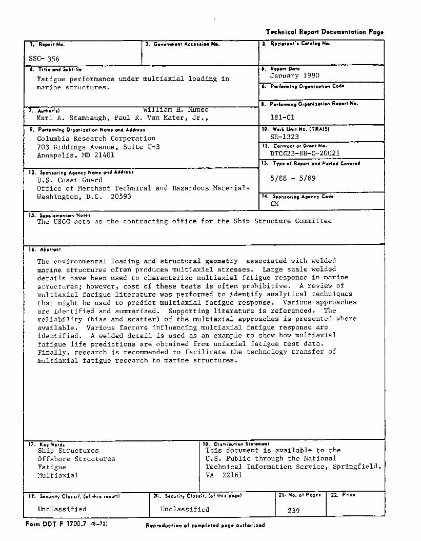
Fatigueperformanceundermultiaxialloadinginmarinestructures.
~6. Porfo*ltie Orgonlzotton Coda
KarlA. Stambaugh,Paul R. Van Mater,Jr., ] lel-ol1
9. Porfo~ing Or~mixotion Nemo md Addr*s~ I1O. work Umii Ne. (TRAls)
ColumbiaResearchCorporation703 GiddingsAvenue,SuiteU-3Annapolis,MD 21401 P====13, TYpoef Roperiond Period Covmrod
12. $ponJerinQ Agoncytdemo ond Addr**~4
U.S. CoastGuard 5/E8 - 5/89Officeof MerchantTechnicaland HazardousMaterialsWashington,D.C. 20593 14. Spenserino ApoticY C*d-
GI!
15. suPPiomsntory NOt*$The USCG actsas the contractingofficefor the Ship StructureCommittee
16. Abstrscf
The environmentalloadingand structuralgeometry associatedwith weldedmarinestructuresoftenproducesmultiaxialstresses. Largescaleweldeddetailshave beenused to characterizemultiaxialfatigueresponsein marinestructures;however,costof thesetestsis oftenprohibitive.A reviewofmultiaxialfatigueliteraturewas performedto identifyanalyticaltechniquesthatmightbe used to predictmultiaxialfatigueresponse. Variousapproachesare identifiedand summarized.Supportingliteratureis referenced.Thereliability(biasand scatter)of the multiaxialapproachesis presentedwhereavailable.Variousfactorsinfluencingmultiaxialfatigueresponseareidentified.A weldeddetailis used as an exampleto showhow multiaxialfatiguelifepredictionsare obtainedfromuniaxialfatiguetest data.Finally,researchis recommendedto facilitatethe technologytransferofmultiaxialfatigueresearchto marinestructures.
17. K,, Ward, I 1S. Distribution S!nt~rntSh~p”Structures This documentis availableto theOffshoreStructures U.S. Publicthroughthe NationalFatigue TechnicalInformationService,Springfield,Multiaxial VA 22161
9. ~.curit~ CIBl*il. (ef this report) I 20.SocuritY Cl*8zif. (ofthisp8s*) 21. No. mf Pogrs
I
22. Prir*
Unclassified Unclassified 239
FormDOT F 1700.7(B-72) Rcproduc!ionof complet.dpoge ourhotizod
METRIC CONVEFISION FACTORS
:— .———— u*-=———-- z———————— z~——— —m— .—.————— 5~———— z——————~ 5——.———— 5——————— .——————.> 2——————— 5—== z=.————. .————— .~————— .————— .~_—
——— G——.-—— .————— .—————— -—.——— ..
—E~— “
ApprrmimmtcConwsions 10 M#tric Mc#surts A~proxim#to Cmrwrsiorrs Irom Metric M*asrnr#s
SVmhlSymbol
4nrv“dIll,
m?fr’ydzmi~
M
lb
lspTbspII OzcNqtgal
ft3yd 3
“F
LEMGTII
LENGTIImnllmutws 0.04cenmn.mmm 0.4ITmmrs 3.3mmlers 1.1hilamtzms 0.6
nm
cm
.mmkm
inin11Vdmi
in chos “2.6ha 30Vmrds 0.9mdms 1.6
Czm ,17wms
Cmt ,mle,s
rmt*,shilmnwrn
cm
cm
m
km
Cmz
#
#
hmah-
0~9t
mlmlml
III
:3
4“3
“c
MEA
U4uHa C9mtkmtus 0,182quw* rrdors 1.2squw. kilmmolzts 0.4hcclmos (10.W m2) 2.6
AREAC#=Z
&
Iu
*q41u* inch- 6.6quzm f401 0.06zqusro Vds 0.8zquars midmm 2.64CS*● O.*
MASS (wsighi)
grzmz 0.036kibx#mm 2.2
Wlws Ilooo kg] 1. I
MASS ~woigfrt)
ounces 2a
*S 0.46Z41mt [ma 0,9
120W lb)
Oz
rb
VOLUME VOLUME
milliliters 0.03#itars 2.1liters 1.031,10,s 0.26cubic nntnls 35Cub#c nwler, 1.3
t*a2p0unstabkspoms
fluid mmcmcupspin$squartsOallonsctibac Imacubic yards
5
15
300.240.4?0.953.a
0.03
0.?6
millililnmm, Ililitor%mltli&iWrs
I,tersIltmrsIilers
tiletscub,c mewscubic meters. TEMPHIATURE [mmct~
Cnlsim 9/6 Ithan
Wnp3rnwm add 32)
TEMPERATURE (mmct) “’c “F
Fahranhe,l 5/9 1?.!1!3! Ctllslllsm.weratu mWrllpwalwa subl,act mg
321 OF 32 9a.6 iz
-40 Q 40 BoI,, I, I: I;*,l J,JJ
120 160 zm
l’; ,! 1 I 1 1 I-:: -20 0 20 40 60 ‘ 80 10D
37 JJc

TABLE OF CONTENTS
1.0
2.0
3.0
INTRODUCTION . . . . . . . . . . . . . . .
1.1 PROJECT OBJECTIVE . . . . . . . . . . . .1.2 sUMMAR Y........ . . . . . . .
FATIGUE IN MARINE STRUCTURES . . . . . . . . .
2.1 STRESS CHARACTERISTICS AND OTHER FACTORSAFFECTING FATIGUE IN MARINE STRUCTURES .
2.1.1
2.1.2
.
●
✎
✎
✎
.
.
.
.
.
Loadina and Stress Characteristicsin Marine Structures . . . . . . .
2.1.1.1 Ship Details . . . . . . .2.1.1.2 Stresses in Offshore
Structures . . . . . . . .
.
.
.
.
.
●
✎
✎
Factors Influencing Fati~ue Response(General) . . . . . . . . . . . . .
2.2 CUMULATIVE DAMAGE AND CRACK GROWTH APPROACHESFOR PREDICTING FATIGUE RESPONSE . . . . . . .
2.2.1 Stress Concentration Factor (SCF)Approach in Offshore Structures . .
2.2.2 Proposed Approach for FatiqueAnalvsis of ShiD Structural Details
2.2.3 Pro~osed Fracture MechanicsApproaches for Marine Structures
2.3 IMPETUS FOR A MULTIAXIAL FATIGUE APPROACH .
REVIEW OF LITERATURE ON MULTIAXIAL FATIGUERESEARCH. . . . . . . . . . . . . . . . . . . .
3.1 GENERAL MULTIAXIAL FATIGUE RESEARCH . . . .
●
✎
✎
✎
●
✎
✎
✎
●
✎
✎
●
.
.
.
.
.
●
✎
✎
✎
✎
✎
✎
●
✎
✎
●
w1-1
1-1
1-1
2-1
2-1
2-1
2-1
2-15
2-23
2-29
2-31
2-36
2-37
2-38
3-1
3-1

m3.1.2 Fatique Crack Pro~affation Research . . 3-33
3.1.2.1 Obsenations of Mixed ModeCrack Growth . . . . . . . . . 3-33
3.1.2.2 Prediction of Mixed ModeCrack Growth Rates . . . . . . 3-36
3.2 FATIGUE RESEARCH ON WELDED DETAILS . . . . . . . 3-46
3.2.1
3.2.2
4.0 APPLICATION OF
Fatiaue Life Estimates . . . . . . . . 3-46
Fatique Pro~aqation in WeldedStructures . . . . . . . . . . . . . .3-52
MULTIAXIAL FATIGUE RESEARCH TOtiRINESTRUCTURES . . . . . . . . . . . . . . . . . . 4-1
4.1 SHIP STRUCTURE APPLICATIONS . . . . . . . . . . . 4-1
4.2 OFFSHORE STRUCTURE APPLICATIONS . . . . . . . . . 4-6
4.3 FACTORS INFLUENCING MULTIAXIAL FATIGUERESPONSE IN MARINE DETAILS . . . . . . . . . . . 4-9
4.3.1
4.3.2
4.3.3
4.3.4
4.3.5
4.3.6
4.3.7
4.3.8
Multiaxial Stress Fields . . . . . . . 4-31
Mean Stress. . . . . . . . . . . . . . 4-34
Stress Gradient . . . . . . . . . . . . 4-34
Residual Stresses . . . . . . . . . . . 4–37
Corrosion. . . . . . . . . . . . . . .4-39
Geometrv, Fabrication Treatment,Defects. . . . . . . . . . . . . . . .4-42
Size - Thickness . . . . . . . . . . . 4-42
Material Strenath . . . . . . . . . . . 4-43

m5.0 EVALUATION OF MULTIAXIAL FATIGUE RELIABILITY . . . . . 5-1
5.1 RELIABILITY FORMAT FOR EVALUATING MULTIAXIALFATIGUE IN MARINE STRUCTURES . . . . . . . . . . 5-1
5.2 RELIABILITY OF MULTIAXIAL FATIGUE RESEARCH . . . 5-4
5.3 EVALUATION OF MULTIAXIAL FATIGUE RELIABILITYFOR MARINE STRUCTURES. . . . . . . . . . . . . . 5-7
6.0 CONCLUSIONS AND RECOMMENDATIONS . . . . . . . . . . . 6-1
6.1 CONCLUSIONS. . . . . . . . . . . . . . . . . . . 6-1
6.2 RECOMMENDED MULTIAXIAL FATIGUE RESEARCH . . . . . 6-3
6.2.1 Define SDacial and TenmoralCharacteristics of PrinciDal Stressesin Ship and Offshore Welded Details . . 6-3
6.2.2 Conduct Multiaxial Fatique TestsOn Marine Structural Details . . . . . 6-4
6.2.3 Inteqrate Multiaxial FatiffueResearchInto A Reliability Based Format . . . . 6-4
REFERENCES. . . . . . . . . . . . . . . . . . . . . . . . R-1
APPENDIX A - BIBLIOGRAPHY ON MULTIAXIAL FATIGUE . . . . . A-1
APPENDIX B - EXAMPLES OF MULTIAXIAL FATIGUE LIFEPREDICTIONS FOR A LATERALLY LOADED PLATEWITH A TRANSVERSE BUTT WELD . . . . . . . . B-1

LIST OF TABLES
2-1
2-2
2-3
3-1
3-2
3-3
3-4
3-5
4-1
4-2
4-3
4-4
4-5
5-1
B-1
Various Stresses in Ship Structural Details . . . . .
Influence of Various Stresses on Fatigue inOffshore Structural Details . . . . . . . . . . . . .
A Summary of Factors and Considerations Related toFatigue in Welded Joints of Offshore Platforms . . . .
Summary of Multiaxial Fatigue Approaches forPredicting Fatigue Life Based on CumulativeDamage Approaches . . . . . . . . . . . . . . . . . .
Angle of Crack on Surface as Function of StrainState . . . . . . . . . . . . . . . . . . . . . . . .
List of the Conditions for Choosing the ProperTerms, LingandWoo . . . . . . . . . . . . . . . . .
Re-Analysis of Plate Girder Data by Moyer . . . . . .
Research on Butt Welds and Crusiform Fillet Weldsby Lawrence . . . . . . . . . . . . . . . . . . . . .
Summary of Methods for Estimating FatigueResponse to Complex Loading . . . . . . . . . . . . .
General Configuration of Various Specimen Types . . .
Fatigue Strengths of Various Specimen Types . . . . .
HY Steel Test Members Used to InvestigateMultiaxial Fatigue Response . . . . . . . . . . . . .
Effect of Mean Stress on Fatigue Strength ofVarious Members . . . . . . . . . . . . . . . . . . .
Potential Improvements in Overall ReliabilityUsing Multiaxial Fatigue Procedures . . . . . . . . .
Summary of Fatigue Results . . . . . . . . . . . . . .
2-2
2-18
2-27
3-31
3-34
3-42
3-49
3-53
4-2
4-1o
4-14
4-28
4-35
5-8
B-3

2-1 Global Stresses Due to Combined Vertical and LateralBendingandTorsion . . . . . . . . . . . . . . . . .
2-2 Cutout inaTankerWeb Frame . . . . . . . . . . . . .
2-3 Predicted Stress Distribution in a Tanker Web Frame .
2-4 Constituent Loadings on Structural Web Frame . . . . .
2-5 Predicted Stress Distribution in Clearance CutoutsinaBulkCarrier . . . . . . . . . . . . . . . . . .
2-6 Stress Distribution in Clearance Cutouts for FatigueTests . . . . . . . . . . . . . . . . . . . . . . . .
2-7 Global Stresses Acting on Hatch Opening . . . . . . .
2-8 Stress Distribution in a Containership Hatch Corner .
2-9 Fracture of the Forward Hatch Cutout on the HighSpeed Containership During the Second Winter Season .
2-10 Biaxial Stress Distribution in a Tanker CVK . . . . .
2-11 Biaxial Stresses in Bottom Plate TransverseButt Weld . . . . . . . . . . . . . . . . . . . . . .
2-12 Illustration ’of an Offshore Platform withMultibrace Connections . . . . . . . . . . . . . . . .
2-13 Typical Joint Geometry/Loading Configuration . . . . .
2-14 Comparison of Stress Concentration Factors withParametric Equations . . . . . . . . . . . . . . . . .
2-15 Stress Concentration Factors for T andNon-Overlapping K, and TK Joints Under VariousTypes of In-Plane Loading . . . . . . . . . . . . . .
2-16 Stress Distribution Around Circumference of aT-Joint Under Various Loads . . . . . . . . . . . . .
2-3
2-5
2-6
2-7
2-7
2-8
2-9
2-1o
2-12
2-13
2-14
2-16
2-17
2-19
2-20
2-21

LIST OF FIGURES (continued)
2-20 Schematic Representation of Crack Growthin Steels . . . . . . . . . . . . . . . . . . . . . .2-32
2-21 Illustration of Stress Concentration Factors and
3-1
3-2
3-3
3-4
3-5
3-6
3-7
3-8
3-9
Hot-Spot Stress for Offshore Structures . . . . .
Schematic Representation of High Cycle and LowCycle Fatigue as a Function of Strain State andStrain Amplitude. . . . . . . . . . . . . . . . .
Comparison of Predicted Combined Bending-TorsionFatigue Limit with Tests Data for aCircumferentially Notched Round-Bar Specimen . . .
Comparison of Life Predictions Based on the TrescaEquivalent Strain Criterion with SAE Test Data . .
Comparison of Life Predictions Based on thevon Mises Equivalent Strain Criterion withIn-Phase SAE Test Data, Taking CircumferentialNotch Strain as Poisson’s Ratio times NotchBending Strain. . . . . . . . . . . . . . . . . .
Comparison of Life Predictions Based on thevon Mises Equivalent Strain Criterion withIn-Phase SAE Test Data, Using a Variable PoissonrsRatio . . . . . . . . . . . . . . . . . . . . . .
Actual versus Predicted Lives: Maximum PrincipalStrain Theory . . . . . . . . . . . . . . . . . .
Actual versus Predicted Lives: Effective StrainTheory. . . . . . . . . . . . . . . . . . . . . .
Actual versus Predicted Lives: Maximum ShearStrain Theory . . . . . . . . . . . . . . . . . .
Actual versus Predicted Lives: Lohr and Ellison
. .
. .
. .
● ✎
. .
. .
. .
. .
● ✎
2-35
3-3
3-5
3-1o
3-1o
3-11
3-11
3-14
3-14
Theory. . . . . . . . . . . . . . . . . . . . . . . .3-15
3-10 Actual versus Predicted Lives: Kandil, Brown andMillerTheog”. . . . . . . . . . . . . . . . . . . .3-15

LIST OF FIGURES (continued)
3-13 Correlation of Test Data Including Mean StressEffects (a) Lohr and Ellison Parameter and(b) Kandil, Brown and Miller Parameter . . . . . . . . 3-21
3-14 Stage I and Stage II Crack Growth Systems UnderGeneral Multiaxial Cyclic Strains . . . . . . . . . . 3-22
3-15 Uniaxial Stress-Strain Approximation for 1 PercentCR-Mo-VSteel . . . . . . . . . . . . . . . . . . . .3-24
3-16 Plastic Work Per Cycle (Calculated) versus Life toFailure (Obsemed) . . . . . . . . . . . . . . . . . . 3-25
3-17 Plastic Work Per Cycle (Calculated with a WeighingFactor on Shear Work) versus Li”feto Failure(Obsemed) . . . . . . . . . . . . . . . . . . . . . .3-22
3-18 In-Phase vs. Out-of-Phase Straining (Comparison) . . . 3-28
3-19 Elastic and Plastic Strain Energy Densities fora Uniaxial Cyclic Loading Case . . . . . . . . . . . . 3-29
3-20 The Predicted Strain Energy Density W’ versusthe Number of Cycles to Failure, N , forVarious Strain Ratios . . . . . . . . . . . . . . . . 3-30
3-21 Crack Propagation Plotted as Crack Length versusCrack Growth Rate to Compare Mode I, Mixed-Mode,andModeIIGrowth . . . . . . . . . . . . . . . . . . 3-35
3-22 Initial Fracture Angle versus the Ratio ofStress Intensity Ranges K,,and KI . . . . . . . . . . 3-37
3-23 Comparison Between the Proposed Method andLing and Woo Method for a = ‘1.0 . . . . . . . . . . . 3-44
3-24 0 - B Relationship for Biaxiality Ratio, a = -1.0 . . 3-45
3-25 e - B Relationship for Biaxiality Ratio, a = -0.45 . . 3-45
3-26 Details of Various Types of Stiffener . . . . . . . . 3-47
3-27 S/N Diagram for Maximum Bending Stress atFailure Section . . . . . . . . . . . . . . . . . . .3-47
3-28 S/N Diagram for Maximum Principal Tensile StressatFailureSection . . . . . . . . . . . . . . . . . . 3-47

LIST OF FIGURES (continued)
3-29
3-30
3-31
3-32
3-33
3-34
3-35
3-36
3-37
3-38
3-39
4-1
4-2
4-3
4-4
4-5
Specimen Geometry of Tube-to-Plate Welds . . . . . . . 3-51
Finite Element Mesh of Tube-to-Plate Welds . . . . . . 3-54
The Maximum ItWorstCase!tLocal Principal StressRange versus Cycles to Failure . . . . . . . . . . . . 3-55
The ItWorstCaseIILocal von Misesl Effective StressRange versus CyCl@S to Failure . . . . . . . . . . . . 3-56
Findleyts Equivalent Nominal Shear Stress Rangeversus Cycles to Failure . . . . . . . . . . . . . . . 3-57
Illustration of Estimating Stress Intensity byFinite Element Analysis
Predicted Crack Path a aIntersection . . . . . .
Stress Intensity FactorsFlaw (In-Plane Bending)
Stress Intensity FactorsFlaw (Torsion) . . . . .
Stress Intensity FactorsFlaw (Axial Tension) . .
Stress Intensity Factors
- -. . . . . . . . . . . . . . . 3-59
Welded Tubular. . . . . . . . . . . . . . . 3-61
of Weld Toe Surface.**.* ● . . . . . . . . . 3-63
of Weld Toe Surface. . . . . . . . . . . . . . . 3-63
of Weld Toe Surface. . . . . . . . . . . . .** 3-64
of Weld Toe SurfaceFlaw (Out-of-Plane Bending) . . . . . . . . . . . . . 3-64
Tension Member
S-N Curves for
S-N Curves forand HY-130/150
S-N Curves forand HY-130/150
S-N Curves forPlate and TypeRatio R=O . .
and Connector with High Pre-Load . . . 4-8
Type I Specimens of HY-80 Steel . . . . 4-16
Type I Specimens of HY-80, HY-1OOSteels . . . . . . . . . . . . . . . .4-17
Type II Specimens of HY-80, HY-1OOSteels . . . . . . . . . . . . . . . .4-16
Type IVB Specimens of HY-80 SteelVIC of HY-80 Cast Steel at Stress. . . . . . . . . . . . . . . . . . . . 4-18

LIST OF FIGURES (continued)
4-6
4-7
4-8
4-9
4-1o
4-11
4-12
4-13
4-14
4-15
4-16
4-17
S-N Curies for Type IVB Specimens of 1-1/211HY-130/150 Steel and Type XIVA Specimens of 3/411A302B and 70B Steels at Stress Ratio R=O . . . . . . . 4-18
S-N Curies for Type VA and VB Specimens of HY-80and HY-130/150 Steels at Stress Ratio R=O (Life at10% increase in deflection) . . . . . . . . . . . . . 4-19
S-N Curies for Type VA and VB Specimens of HY-80Steel at Stress Ratio R=O (Life at 100% increasein deflection) . . . . . . . . . . . . . . . . . . . .4-19
S-N Curies for Type VA and VB Specimens of HY-80Steel at Stress Ratio R=O (Life at 100% increasein deflection) . . . . . . . . . . . . . . . . . . . .4-20
S-N Curves for HY-80 Type VI Specimens UnderVarious Treatments at Stress Ratio R=O (Life at 10%increase in deflection) . . . . . . . . . . . . . . . 4-21
S-N Curves for HY-80 Type VII Specimens UnderVarious Treatments at Stress Ratio R=O (Life at100% increase in deflection) . . . . . . . . . . . . . 4-21
S-N Curve for Type VII Spimens of HY-80 Steel atStressRatioR=-l . . . . . . . . . . . . . . . . . . 4-22
S-N Curves for Type VII Specimens of HY-80 Steelat Stress Ratios of R=O and R=-1 . . . . . . . . . . . 4-23
S-N Curve for Type VIII Specimens of M. HY-80,HY-1OO and HY-140 Steels at Stress Ratio R=O . . . . . 4-24
S-N Curves for Type IX and X Specimens of HY-80Steel at Stress Ratio R=O . . . . . . . . . . . . . . 4-25
S-N Curves for Type XI Specimens of HY-80 andHY-100Steels . . . . . . . . . . . . . . . . . . . .4-17
S-N Cumes for Type XII and XIII Specimens of HY-80and HY-1OO Steels at Stress Ratio R=-1 . . . . . . . . 4-25
4-18a S-N Cume for Type XIVB Notched Specimens of A302Band 70B Specimens at Stress Ratio R=O . . . . . . . . 4-26
4-18b Comparison of Plain and Notched Type XIV Specimens . 4-26

4-19 Comparison of Axial Fatigue of Type III Specimensand Bending Fatigue of Type VI and VII Specimensat Stress Ratios R=O and R=-1 . . . . . . . . . . . . 4-27
4-20 Modified Goodman Diagram for HY-80 . . . . . . . . . . 4-36
4-21 Comparison of Axial Fatigue of Type II Specimensand Bending Fatigue of Type VB Specimens of HY-80Steel . . . . . . . . . . . . . . . . . . . . . . . .4-38
4-22 S-N Curves for As Welded and Mechanically PeenedType VIB Specimens of HY-1OO Steel at StressRatioR=O . . . . . . . . . . . . . . . . . . . . . .4-40
4-23 Ratio of Fatigue Strength to Tensile Strength forPlain Plate Specimens of HY-80, HY-1OO and HY-130/150 atStressRatioR=0 . . . . . . . . . . . . . ..4-41
B-1 Typical 56 by 28 by 1-1/2” HY-80 SteelButt Welded Plate Elements . . . . . . . . . . . . . . B-3
B-2 S-N DiagramsforHY-80. . . . . . . . . . . . . . . . B-4
B-3 Strain-Life Cumes Showing Total Elastic andPlastic Strain Components . . . . . . . . . . . . . . B-6

1.0
Ships and offshore platforms are designed and built to endurea rugged environment typified by extreme events [1-1, 1-2]that are highly unpredictable. The random seaway is oftencharacterized by amassed probabilities [1-2, 1-3]. Thisrandom seaway acts on marine structures that are designed toresist the random loads by welded structural geometries withintersecting structural members. More often than not theloadings are complex; that is, they produce two or three prin-cipal stresses that may be nonproportional or whose directionsmay change during a cycle of loading. Structural details suchas intersections in longitudinal and transverse framing andadjacent butt welds in ships and nodal joints (K, T) inoffshore structures are a few examples. Complex stresssystems are also common at notches or geometricdiscontinuities. The variable loading of these detailsproduces a fatigue response [1-4, 1-5] under such stresssystems. The multiaxial fatigue response is generallyunaccounted for on a detail level. Computational techniquesfor predicting the state of stress in structural elements haveimproved over recent decades because of the increasedavailability and capability of finite element computerprograms. They also require substantial effort in predictingstresses on a detail level. The fatigue prediction methodsused in practice for designing ship and offshore structures donot generally provide a comparable level of detail becausethey are based on the nominal stress field applied toboundaries of welded configurations.
1.1 PROJECT OBJECTIVE
The objective of this project is to survey and reviewmethodologies for predicting multiaxial fatigue performance ofstructural details pertinent to marine structures. Theresearch should ultimately lead to increased levels ofreliability in designs and performance evaluations of existingstructures and potentially minimize the need to conduct full-scale fatigue tests of ship and offshore structural elements.
1.2 SUMMARY
To accomplish the project objective a detailed literaturesurvey was performed identifying over 600 references onstructural fatigue under complex loading of various structuralconfigurations. The database is presented in Appendix A. Thereferences include multiaxial fatigue approaches used instructural systems such as nuclear reactors, aircraft, gasturbines, automobiles and heavy moving equipment.
The factors affecting fatigue in marine structures werereviewed including the stress characteristics in marine
1-1

structural details. Also , existing fatigue design procedureswere reviewed as a baseline to judge procedures associatedwith multiaxial fatigue approaches and to identify the extentmultiaxial fatigue response is considered in the existingtechniques. Essentially, the existing design approaches arebased on structural components tests where complex stressdistributions are internal to the applied nominal stress fieldboundary.
Several basic multiaxial fatigue approaches were identifiedincluding stress and strain-based approaches where anequivalent stress or strain is correlated to simple uniaxialtest data, critical plane approaches where crack initiation isdependent on a critical stress or strain plane and strainenergy approaches for both crack initiation and crackpropagation. These approaches were reviewed and theengineering significance discussed in Section 3.o. Themultiaxial fatigue approaches were compared to test data fortypical structural details found in marine structuresincluding a web frame cutout, center vertical keel (CVK),hatch corner and a butt weld for ship structures and K and Tjoints in offshore structures. These comparisons indicatethat there are candidate approaches for predicting multiaxialfatigue response in marine structures. The amount ofexperimental verification has been extremely limited and thereare a large number of variables that have not been quantifiedfor marine environments.
To support the evaluation of rnultiaxial fatigue data,statistical characteristics (bias and scatter) were identifiedand compared to existing fatigue design approaches by Munse[1-6], the American Petroleum Institute (API) [1-7] and theUnited Kingdom Department of Energy (UK DOE) [1-8]. There areindications from the data that there are possible gains inreliability to be realized by applying multiaxial fatigueapproaches. However, these gains must be evaluated in contextof the overall system reliability and associated level ofuncertainties and the additional effort required to applymultiaxial fatigue procedures as discussed in Section 5.o.
Finally, recommendations are provided to incorporate themultiaxial fatigue design approaches into a fatigue designprocedure for marine structures including experimental work.
1-2

2*O
Fatigue in marin@ structures is a function of the loadingcharacteristics and a given material’s capability to performwithout developing fatigue cracks in the operationalenvironment. These factors will be examined and engineeringtechniques used to estimate the load and response, and toprovide a proper perspective for reviewing and evaluating theapplicability of multiaxial fatigue research.
2.1 STRESS CHARACTERISTICS AND OTHER FACTORS AFFECTINGFATIGUE IN KARINE STRUCTURES
2.1.1 Loadina and Strsss Characteristics in Marine Structures
There are a number of multiaxial fatigue analysis proceduresfor predicting crack initiation and growth. Each method isapplicable to a specific set of stress, strain, and strainenergy loading characteristics. Each method must be evaluatedby comparing the loading assumed in the multiaxial fatiguecriteria with the actual loading on the structure of interest.Therefore, it is beneficial to review the state of stress intypical marine structural details, many of which are wherefatigue cracks are known to initiate and propagate. Theactual stress distribution in the structural details variesdepending on the operational environment encountered; however,design generalizations are usually made to characterize basicstresses for ships and offshore structures.
2.1.1.1 Ship Details
Sources of fatigue loads on ships are summarized in Table 2-1.Global loads are distributed through the structure via plates,girders and panel stiffeners at welded structural details.
In the steel structure of a ship, the stress or strain cyclesare generally caused by the seaway and by changing still waterbending moments. These loads produce bending stress and shearstress in the ship’s hull girder. These global stresses areillustrated in Figure 2-1 for a typical tanker where verticalbending, lateral bending and torsional bending stressescombine in the primary structural members. Superimposed onthe hull girder loads are local stresses caused by changes inhydrostatic pressure and local loading from ships cargo orballast. As shown in Figure 2-1, the stresses are planestresses within a thin walled plate structural member. In atransverse plane, bending and shear stresses are caused by
2-1

TABLE 2-1VARIOUS STRESSES IN SHIP STRUCTURAL DETAILS
Residual Stress - This includes the locked-in stresses in astructural element which occur during fabrication and assembly aswell as the stresses induced by the support of the ship’s ownstructure. The local stress is then the state of stress thatexists in the light ship condition.
Initial Mean Stress - The still water bending stress (SWBS) maybe induced by the addition of the deadweight which includescargo, fuel and lube oil, potable water, stores, crew andeffects, ballast and light ship bending stress.
Varvin~ Mean Stress - This refers to stress changes due to fuelburn-off, consumption of consumables, and change in ballastingthat affect the total displacement and attitude of the ship and,consequently, the stresses a structural element may experience.
Stress Due to Ship’s Own Wave - This stress is induced by thepressure of the shipis own wave system. Methods are available toestimate the speed dependent bending moment contribution and thusthe stress contribution from the ship’s own wave system.
Diurnal Thermal Stresses - These stresses arise from the thermalexpansion of the topside in the day and contraction during thenight. The thermal stresses are also affected by the amount andlocation of sun exposure occurring during daylight hours.
Low Frequency Wave-Induced Stresses - These stresses are causedby the wave forces on the hull and the ship motions due to theseforces. These cyclic stresses occur at the frequency ofencounter of the ship with the wave system. The level of stressexperienced is directly related to (although @ directlyproportional to) the significant wave height of the encounteredseaway.
Hi~h-Fre~ ency Wave-Induced Stresses - These stresses are inducedby dynamic wave loads which act on the ship’s structure. Themost common are bottom slamming, shipping of water on deck, andflare impact. Dynamic loads produce whipping and springingelastic motions of the hull, typically at higher frequencies thanthe fre~ency of wave encounter. The impact-induced stresseswill produce an initial spike in the stress records followed byhigh-fre~ency vibrations.
2-2

AXIAL SIRESS FROMLONGITUDINAL AND
HORIZONTAL BENDING
// &l
Z-———Y uf3
—SHEAR FROM
ITORSIONAL BENDING
VARYING LATERALHYDROSTATIC LOAD
Figure2-1
GLOBAL STRESSES DUE TO COMBINED VERTICAL ANDLATERAL BENDING AND TORSION
2-3

differences in hydrostatic pressure and internal cargo loadsor ballast.
These stress patterns are transmitted to structural details.The stress patterns in elemental details vary; however, theplaner character of stress remains because the geometry of atypical structure. These stress patterns will be investigatedfurther for specific details where fatigue cracks are known toexist for a web frame cutout, a hatch cover detail, a CVK anda bottom plate butt weld.
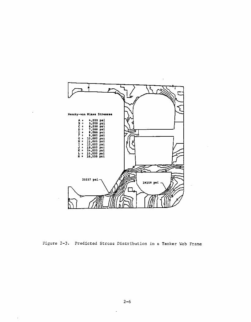
The web frame cutout detail was chosen as an example detailbecause of frequent cracking found in the web plating. Figure2-2 shows the location of the cutout under consideration.This detail is commonly found in tankers. The state ofstresses was investigated by ABS [2-1] and is illustrated inFigure 2-3. The stress patterns in the cutout wereinvestigated by Fricke [2-2] for a similar cutout in a bulkcarrier. The constituent loadings are illustrated in Figure2-4 and the resulting stress patterns are shown in Figure 2-5.This cutout detail was also fatigue tested by Munse [2-3].The stress distribution was measured by Munse with straingauges as shown in Figure 2-6. The load was applied as aconcentrated load between cutouts, however, the stresspatterns are consistent with those shown in the previousfigures. The constituent stress characteristics in thevicinity of the cutout are biaxial. However, the stress isuniaxial on the extreme fiber of the cutout. This is becausea free surface cannot support stress normal to the surface.Shear strains can exist near the free surface. Anotherimportant characteristic is the stress concentration thatexists around the cutout. This concentration produces localstresses that can exceed yield while adjacent biaxial fieldstresses are well below yield. The behavior has beenconfirmed by stress predictions for this cutout conducted byABS [2-1] and can result in strain-controlled fatiguecracking. Fricke [2-2] also describes this strain-controlledphenomenon for a similar structural detail.
Hatch corners often experience excessive stresses that lead tofatigue cracking. Compressive and tensile stresses resultfrom longitudinal and lateral bending due to the hogging orsagging condition. Also, torsionally induced hull stressesare high and common in large hatch ships. Figure 2-7illustrates a hatch opening through a deck with associatedstresses present. These stresses concentrate around thecorners of the hatch opening. Figure 2-8 illustrates stress
2-4

typicalWhvbSoight
/1—---————--—~I
/==-
/’bQE?L ~1 Initiationof Crack in Flatau Stiffener
2 Crack ●t Free Etigt of cut-out3 hack in Side Shell Plating
4 Crack ●t Rmdius of Cut-out
Figure2-2. Cutoutin a TankerWeb Frame
2-5
I
Hencky-von Mimes Stremmos
A. 4,000 psi. 5,000 psi
:; 6,000 pB~7,000 pai
-;: 8,000 psiF: S,000 psiG . 10,000psiH = 11,000 psiI = 12,000 psiJ E 13,000psiK: 14,000psiL= 1s,000psiH = 16,000p=i
20237 pei>
Figure2-3. PredictedStressDistributionin a TankerWeb Frame
2-6

~● LOAOCASE1 mIh1.
SYMMETRIC LOADS F1
ON LONGITUOINALS.-+ -. ~.. -
I.+L;.I
● LOAD CASE 2: &
wANTIMETRIC LOADS F2 - ,} +
ON LONGITUDINAL4A
~
● LOAD CASE 3:
NORMAL FORCE N
● LOAD CASE L :
SHEAR FORCE S
● LOAD CASE 5:
BENDING MOMENT M
SHIP IN BALLAST
ON WAVE CREST
LOADS:p-o
LOCALI
PRESSURE : ~ob[o~qmqoi{dil!ftll lllttttftltttltl
NOMINAL
STRESS
DUE TO S,M :
STRUCTURAL
DETAIL AT:
INNER
BOTTOM
OUTER
BOTTOM
p. 70kNlm2
Tn8 U3Mlmm2
Wn=:70 Nlmm2
‘t Is
.+
IiKEiiM; ii k ;
(, t + ;.,)M....
SHIP FULLY LOADED
IN WAVE TROUGH
Illlllllllllllllltl
p. 9SkN/m2
Tn. -S8 Nlmm2
Un. ;L9 N/mm2
Figure2-4. ConstituentLoadingson StructuralWeb -Frame
Figure2-5. PredictedStressDistributioninClearanceCutoutsin a Bulk Carrier
SCALE * r,: $00 !OOONlmm2
‘~2-7
0 73 145 KSI

(51)
2
12.19T
12.1971
Ur,:F,77~:;T
2L97C 12.55T
t
(a) Stresses at Strain Gage Locations for50k Load (ksi)
4T
(51) (52)
J
(b) Stresses at Strain Gage Locations for 75k Load (ksi)
Figure2-6. StressDistributionin ClearanceCutoutsfor FatigueTests
2–8

Figure2-7
GLOBAL STRESSES ACTING ON HATCH OPENING
2-9

m 2-0
ORIGINAL DESIGN HOBI?MD STWCZRI
~RSION
Gy
Figure2–8. StressDistributionin a ContainershipHatch Corner
2-1o
patterns that were determined for a class of containershipsfrom finite element analysis.
The stresses that act on an element of the deck platesurrounding a hatch corner are tensile, compression, andshear. The proportionality of principal stress is variable,depending on the status of mean stresses and encounteredwaves. Stresses in hatch corners were measured as part of thewell known and well documented SL-7 instrumentation program[2-4]. Stresses in excess of yield were measured in thevicinity of the hatch corner. Fatigue cracking occurred earlyin the ships service life as documented by Stambaugh [2-5] andothers [2-6] and shown in Figure 2-9. The fatigue crackgrowth is along a path perpendicular to the maximum principalstress field indicative of Mode I crack extension. Again, alocal strain controlled condition exists where local stressesare in excess of yield and nominal stresses are below yield inthe vicinity of a stress concentration.
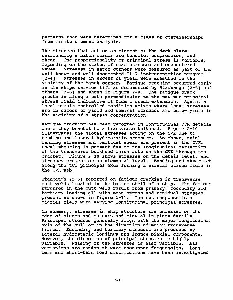
Fatigue cracking has been reported in longitudinal CVK detailswhere they bracket to a transverse bulkhead. Figure 2-10illustrates the global stresses acting on the CVK due tobending and lateral hydrostatic pressure. As shown, axialbending stresses and vertical shear are present in the CVK.Local shearing is present due to the longitudinal deflectionof the transverse bulkhead which acts on the CVK through thebracket. Figure 2-10 shows stresses on the detail level, andstresses present on an elemental level. Bending and shear actalong the two principal axes forming a biaxial stress field inthe CVK web.
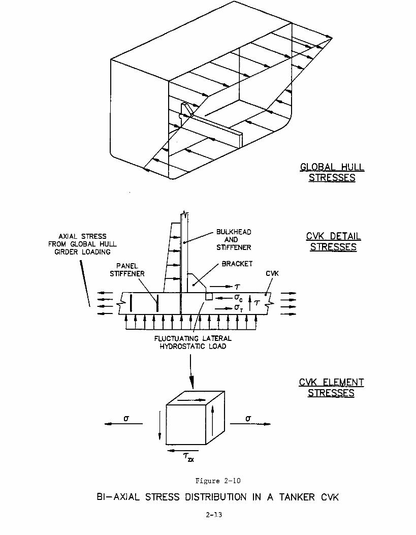
Stambaugh [2-5] reported on fatigue cracking in transversebutt welds located in the bottom shell of a ship. The fatiguestresses in the butt weld result from primary, secondary andtertiary loading all with mean stress and residual stressespresent as shown in Figure 2-11. The net response is abiaxial field with varying longitudinal principal stresses.
In summary, stresses in ship structure are uniaxial on theedge of plates and cutouts and biaxial in plate details.Principal stresses generally align with the major longitudinalaxis of the hull or in the direction of major transverseframes. Secondary and tertiary stresses are produced bylateral hydrostatic loadings and induce biaxial components.However, the direction of principal stresses is highlyvariable. Phasing of the stresses is also variable. Allvariations are random at wave encounter frequencies. Long-term and short-term load distributions have been investigated
2-11

n ?90
k \~~.<~” l;\
r+ I7—————.._— —————.——!l~
1 / I <
~)\——.—.——————\,1 / I
+---LY——-
[ l’!
II III II
II
\I
\I
1L I——— I-1——.—I
Figure2–9. Fractureof the ForwardHatch Cutouton the EighSpeedContainershipDuringthe SecondWinterSeason
●
2-12
GLOBAI HULLSTRESSES
7
AXIAL STRESSBULKHEAD
-FROM GLOBAL HULL w AND
GIRDER LOADING - SllFFENER
\
PANEL ~
SnFFENER Cvu
1-l_l~uc
t f~
~
~DT T ~
tlttt#lttt!ttt
u
FLUCTUATING LATERALHYDROSTATIC LOAD
CVK DETAILSTRESSES
CVK FLEMENTSTRESSES
Figure2–10
BI–AXIAL STRESS DISTRIBUTION IN A TANKER CVK
2-13
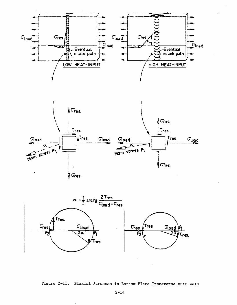
44-*
‘load~ Gr~
/’
HIGH HEAT-INPUT—— ——
4Crw,
Tres.
I..Gres.dl 2 GM.
=7 atg% d - %.
Figure2-11. BiaxialStressesin BottomPlateTransverseButt Weld
2-14
extensively with little agreement between researchers as tothe exact type of distribution that will account for randomload effects. Mean stresses should also be taken intoaccount. Also, large residual stresses are present from theweld process, in many instances on the order of magnitude ofyield, and effect the mean stress level.
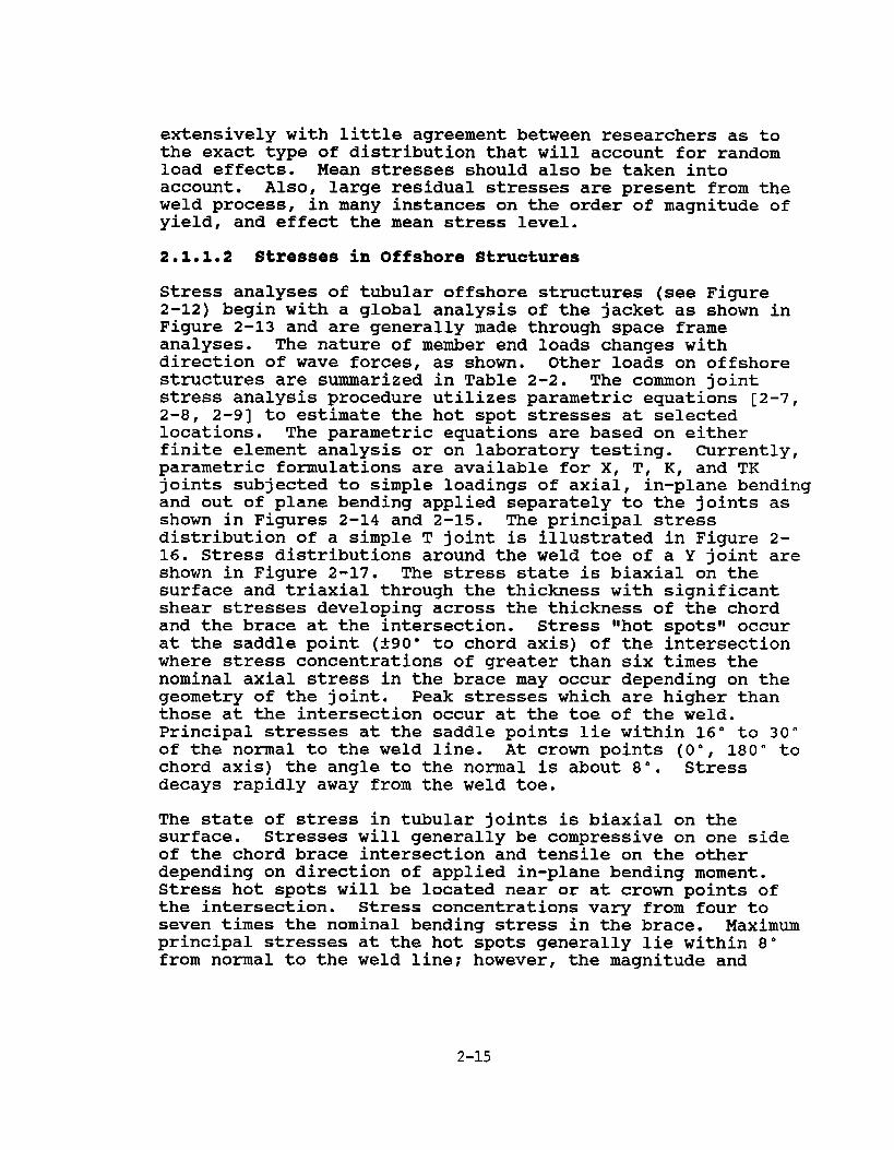
2.1.1.2 Stresses in Offshore Strmtures
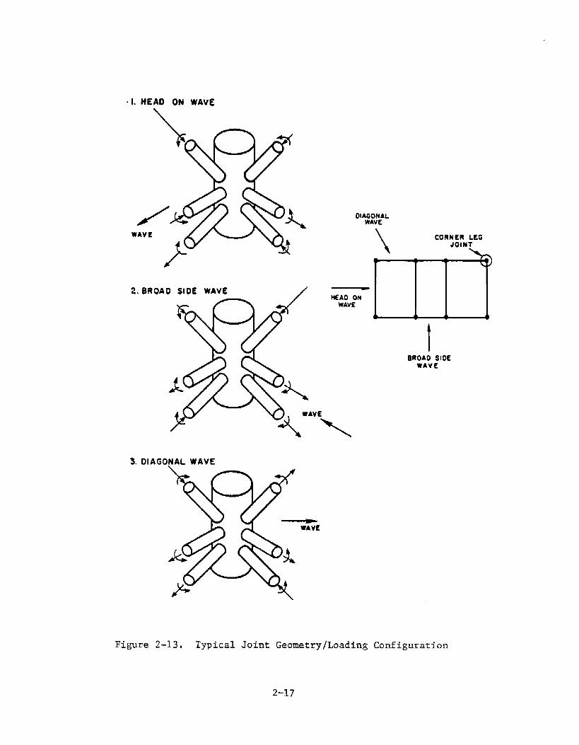
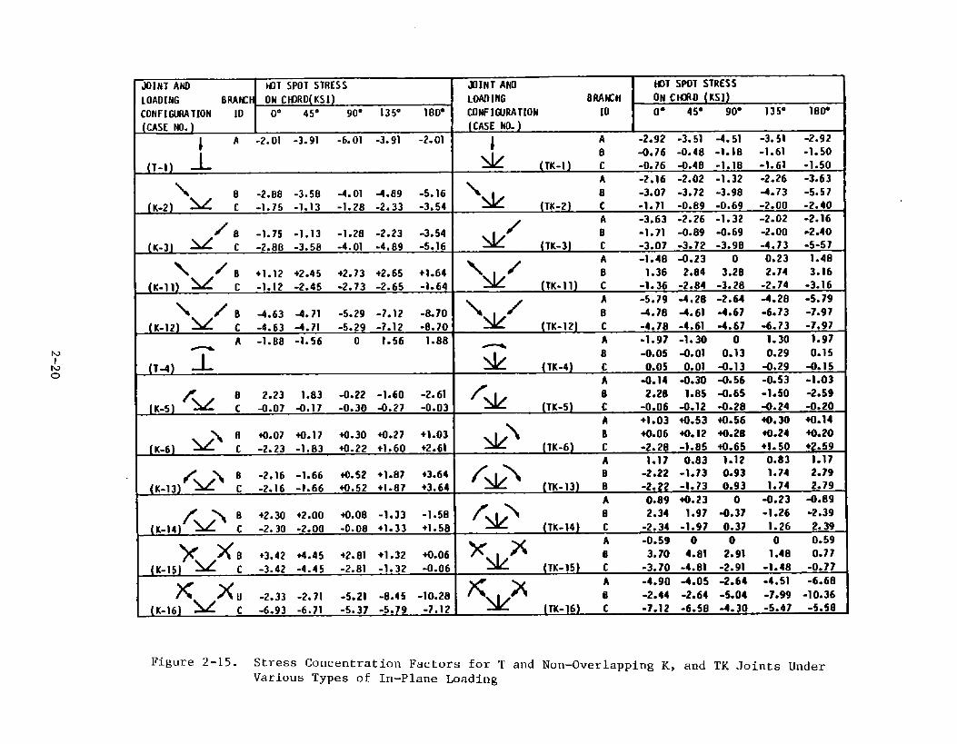
Stress analyses of tubular offshore structures (see Figure2-12) begin with a global analysis of the jacket as shown inFigure 2-13 and are generally made through space frameanalyses. The nature of member end loads changes withdirection of wave forces, as shown. Other loads on offshorestructures are summarized in Table 2-2. The common jointstress analysis procedure utilizes parametric equations [2-7,2-a, 2-9] to estimate the hot spot stresses at selectedlocations. The parametric equations are based on eitherfinite element analysis or on laboratory testing. Currently,parametric formulations are available for X, T, K, and TKjoints subjected to simple loadings of axial, in-plane bendingand out of plane bending applied separately to the joints asshown in Figures 2-14 and 2-15. The principal stressdistribution of a simple T joint is illustrated in Figure 2-16. Stress distributions around the weld toe of a Y joint areshown in Figure 2-17. The stress state is biaxial on thesurface and triaxial through the thickness with significantshear stresses developing across the thickness of the chordand the brace at the intersection. Stress ‘ihotspotslloccurat the saddle point (t90” to chord axis) of the intersectionwhere stress concentrations of greater than six times thenominal axial stress in the brace may occur depending on thegeometry of the joint. Peak stresses which are higher thanthose at the intersection occur at the toe of the weld.Principal stresses at the saddle points lie within 16° to 30”of the normal to the weld line. At crown points (O”, 180” tochord axis) the angle to the normal is about 8“. Stressdecays rapidly away from the weld toe.
The state of stress in tubular joints is biaxial on thesurface. Stresses will generally be compressive on one sideof the chord brace intersection and tensile on the otherdepending on direction of applied in-plane bending moment.Stress hot spots will be located near or at crown points ofthe intersection. Stress concentrations vary from four toseven times the nominal bending stress in the brace. Maximumprincipal stresses at the hot spots generally lie within 8°from normal to the weld line; however, the magnitude and
2-15

.e&.-.s—- “
>---
.
---,-,-.
. .. -.
.. .. .
.
.----.. -
Figure2-12. Illustrationof an OffshorePlatformwith MultibraceConnections
2-16
. L HEAD ON WAVE
w
/
2.BROAD SIDE WAVE /
3.DIA GONAL WAVE
DlA$&P4EAL
\
CORNER LEGJOINT
HEAD ONWAVE
m
BROAD SIDEWAVE
Figure2-13. TypicalJoint Geometry/LoadingConfiguration
2-17

TABLE 2-2
INFLUENCE OF VARIOUS STRESSES ON FATIGUEIN OFFSHORE STRUCTURAL DETAILS
TYPE OF LOADING
Wave
Current and Wind(Static andQuasi-Static)
Current and Wind(Dynamic)
Deadweight
Fabrication
Launching/Installation
Live Loads
Transportation
Buoyant and Hydrostatic
Foundation Movement/Earthquake
Floating Ice Impacts
CONTRIBUTION
Fatigue Crack Initiation andPropagation
Mean Stress (R ratio) in CrackInitiation and Propagation
Fatigue Crack Initiation andPropagation
Mean Stress (R ratio) in CrackInitiation and Propagation
Mean Stress (R ratio) in CrackInitiation and PropagationFatigue Crack InitiationInitial Flaw Size in CrackPropagation
Crack Initiation
Fatigue Crack Initiation andPropagation
Low-Cycle Fatigue Crack Initiationand Propagation
Mean Stress (R ratio) in CrackInitiation and PropagationCrack Initiation
Low-Cycle Crack Initiation
Crack Initiation
2-18

MOTES: s =c.
IRAMIJ FINITE ELEMEHT AMLfitS PAR/U4ElRI
10 CWUI [OIJISIOEWFACE) KIMHG UOROWOIUHo* 45“ 90* 135” lao* CM3RD cMIRD
h -2.01-3.91-6.01-3.91-2.01 4.67 6.16’2.916
A -1.M -1.58 0 1.58 1.88 l.sa 2.03C
B 1.12 2.45 2.78 2.73 1.64 2.80 2.36°2*50=
c -1.12-2.45-2.78-2.73-1.64 -2.80 2.36’2*5ti
8 -2.23-1.83 0.22 1.60 2.61 2.53 2.68c 0.07 O*17 0.30 0.27 1.03
A -1.484.23 0 0.23 1.48B 1.36 2.84 3.28 2.74 3.16 3.51 3.52c -1.36-2.84-3.28-2.74-3.16 3.51 3.52
SAIMKE POINT (90’ POSITION)
f310UN POIMT (O” or 180” FWS1TION)
## uA
“0’”
(
Figure2-14. Comparisonof StressConcentrationFactorswith ParametricEq
JOINT ANO HJT SPOTSTRESS
LOAOING BRAtKH ON CWRO(KS1)CONFIGURATION IO 0° 45° 90” 135” 180”
jCASE Ml.)
1 A -2”0’ ‘3”91 ‘6”01 ‘3”9’ ‘2”0’
(,-,] 1
\(~.~] M ; :;:;: :;:::
-4.01 4.89 -5.16-1. ?8 -2.33 -3*54
/ B .1.75 .1.13 .1.213 .2.23 .3.54(K.3] ~ C -?.88 -3.5B -4.01 -4.89 -5.16
~ z B +1.12 +2.45 +2.73 +2.65 +1.64(K-l]) = C -1.12 -2.45 -2.73 -2.65 -1.64
\ / B 4.63 -4.71 -5.29 -7.12 -8.?0
(K-12) = C -4.63 -4.71 -5.29 -7.12 -8.70A -1.8B -1.56 0 1.56 1.88
lTAI T
f(K-5] = t -% ;~f;
-0.22 -1-60 -2.61
-0.30 **27 -0.03
\ R +0.07 +0.17 +0.30 +0.2? +1.03(K-6) ~ C -2.23 -1.83 +0.22 tl.60 +2.61
/ \ B -2*16 -1”66 4“52 ‘1”87 ‘3”64(K-13) ~ C .2.16 -1.66 tO.52 +1.87 +3.64
K-14 &~ ~ ‘;”: ‘;~~ +0.08 -]-33 .1*5B-0.08 +1.33 +~.5f
K-,5X’MX::;:::;:::+2.81+1.32+0.06-2.81 -1.32 -0.0(
x x“ ‘: ::
(K.lfj) M c ::.;: -:.;:-5* 21 -8.45 -lo*2f-5.37 -5. ?9 -7.1:
lJINT ANOLOAOfMG 8RAt&ti
CONFJCURATION IO(CASE w.)
HOTSPOT STRESSON CIKMII(KSI)
o“ 45“ 90” 135° 18LP
I A -2.92 -3. 5) -4.51 -3.51 -2.92
& 8 -0.76 -0.48 -1.18 -1.61 -1.50
(TK-1) c -0.76 -0.48 -1.18 -1.61 -1.50
A -2.16 -2.02 -1.32 -2.26 -3.63
‘u8 -3.07 -3,72 -3.98 -4.73 -5.57
{TK-2) c -1.71 -0.89 -0.69 -2.00 -2.40
/A -3.63 -2.26 -1.32 -2.02 -2.16
.1/ B -1.71 -0.89 -0.69 -2*OO *2 .40
(TK-3) c -3.07 -3.72 -3.98 -4.73 -5-57
\,/A -1.48 -0.23 0 0.23 1.48
. . B 1.36 2.84 3.28 2.74 3.16(TK-11) C -1.36 -2.84 -3.28 -2.74 -3.16
\ * A -5.79 -4.28 -2.64 4.20 -5.79\/w B 4.70 -4.61 4.67 -6.73 -7.97
[TK-12) c -4.78 -4.61 -4.67 -6.73 -7.97
~ A -1.97 -1.30 0 1.30 1.97
*8 -0.05 -0.01 0.13 0.29 0.?5
(TK-4) c 0.05 0.01 -0.13 43.29 -0.15A
/*
-0.14 -0.30 -0.56 -O*53 -1.038 2.20 1.85 -0.65 -I*5O -2.59
(TK-5) c -0.06 -0.?2 -0.2a -0.24 -0.20
\
A +].03 443.53 +fJ.56 +0.30 +0.14
.l# B +0.06 +0.12 @.28 +0.24 40.20(TK-6) c -2.28 -1.85 +0.65 tl.so +2. 59
A 1.17 0.83 1.12 0.83 1.17
A@ B -2.22 -I*73 O*93 1.74 2.?9
(TK-13) B -2.22 -I*73 O*93 1.74 2.79
A
f*b
0.89 +0.23 O -0.23 -0.89
B 2.34 1.97 -0.37 -1.26 -2.39
{TK-14) c -2.34 -1.97 0.37 1.26 2.39
X*XA -0.59 0 0 0 0.598 3.70 4.81 2.91 1.40 0.17
(TK-15) c -3.70 -4.81 -2.91 -1.48 -0.77
K*%A -4.90 -4.05 -2.64 -4.51 -6.68
B -2.44 -2.64 -5.04 -7*99 -10.36[TK-16) C -7.12 -6.58 -4.30 -5.47 -5.58
Figure2-15. S~ressConcentrationFactorsfor T and Non-OverlappingK, and TK JointsUnderVariousTypes of In-PlaneLoading

n--T--r’.
A\\\l/
I
110Usl
AL
L
, 10 KSI
Figure2-16. StressDistributionAroundCircumferenceof a T-JointUnderVariousLoads
2-21

mI
E
STRESS DISTRIBUTION AT 12H FULL PENETRATION, TWO-SIDE WELD
NUMBERSDENOTESCF VALUES
Figure2-17. StressDistributionat a WeldedY–JointConnectionwith an Axial Load
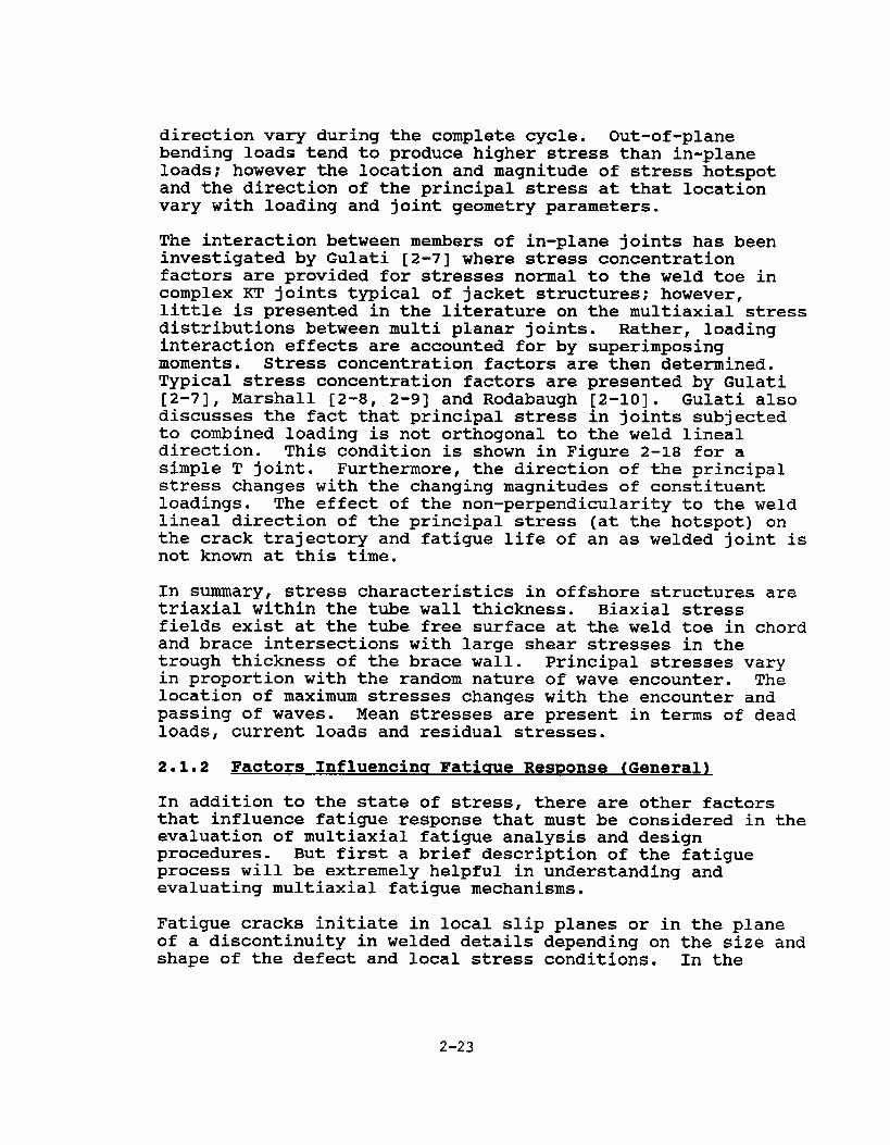
direction vary during the complete cycle. Out-of-planebending loads tend to produce higher stress than in-planeloads; however the location and magnitude of stress hotspotand the direction of the principal stress at that locationvary with loading and joint geometry parameters.
The interaction between members of in-plane joints has beeninvestigated by Gulati [2-7] where stress concentrationfactors are provided for stresses normal to the weld toe incomplex KT joints t~ical of jacket structures; however,little is presented in the literature on the multiaxial stressdistributions between multi planar joints. Rather, loadinginteraction effects are accounted for by superimposingmoments. Stress concentration factors are then determined.Typical stress concentration factors are presented by Gulati[2-7), Marshall [2-8, 2-9) and Rodabaugh [2-10]. Gulati alsodiscusses the fact that principal stress in joints subjectedto combined loading is not orthogonal to the weld linealdirection. This condition is shown in Figure 2-18 for asimple T joint. Furthermore, the direction of the principalstress changes with the changing magnitudes of constituentloadings. The effect of the non-perpendicularity to the weldlineal direction of the principal stress (at the hotspot) onthe crack trajectory and fatigue life of an as welded joint isnot known at this time.
In summary, stress characteristics in offshore structures aretriaxial within the tube wall thickness. Biaxial stressfields exist at the tube free surface at the weld toe in chordand brace intersections with large shear stresses in thetrough thickness of the brace wall. Principal stresses varyin proportion with the random nature of wave encounter. Thelocation of maximum stresses changes with the encounter andpassing of waves. Mean stresses are present in terms of deadloads, current loads and residual stresses.
2.1.2 Factors Influencing Fatique ResBonse (General)
In addition to the state of stress, there are other factorsthat influence fatigue response that must be considered in theevaluation of multiaxial fatigue analysis and designprocedures. But first a brief description of the fatigueprocess will be extremely helpful in understanding andevaluating multiaxial fatigue mechanisms.
Fatigue cracks initiate in local slip planes or in the planeof a discontinuity in welded details depending on the size andshape of the defect and local stress conditions. In the
2-23
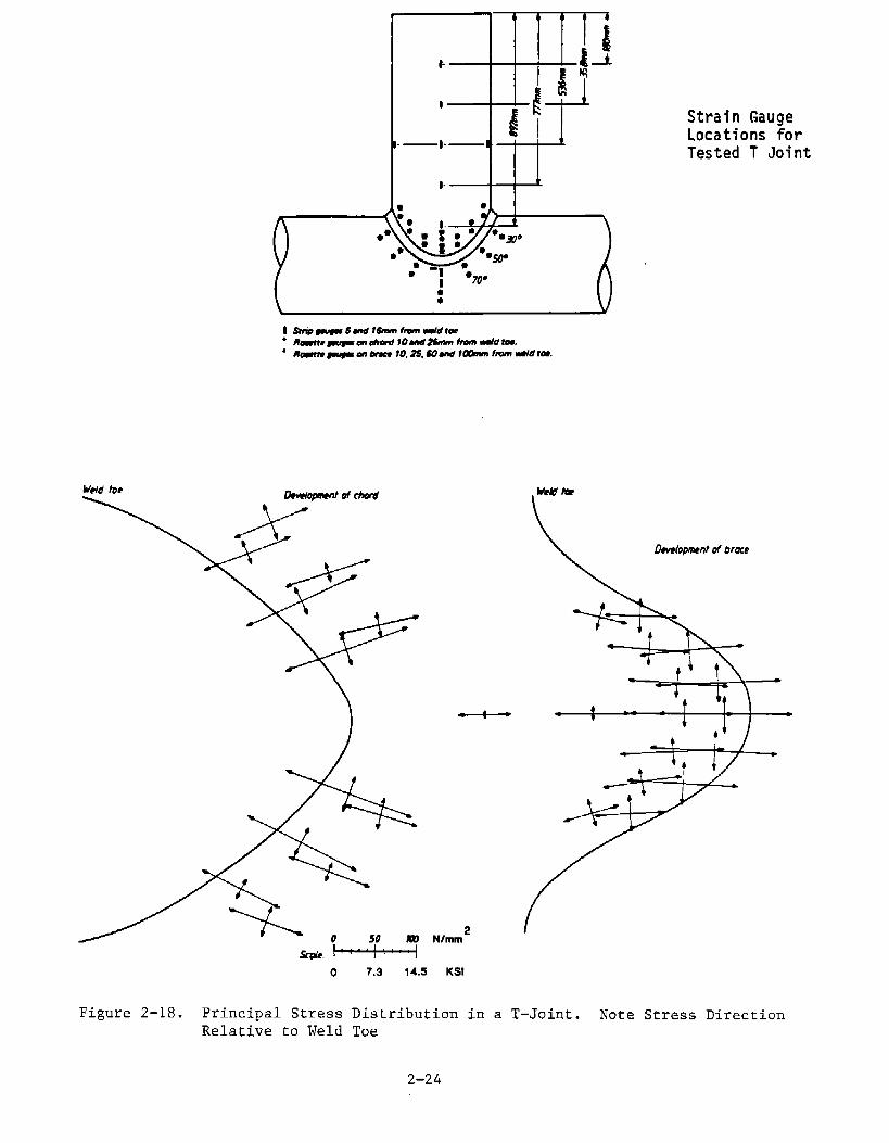
Strain GaugeLocations forTested T Joint
W@d tmIkdapmnt of M
Dndopmentd brace
\
WC
o 7.3 14.5 KSI
PrincipalStressDistributionin a T–Joint. Note StressDirectionRelativeto Weld Toe
Figure2-18.
2-24

absence of defects, fatigue cracks tend to grow in a plane ofmaximum shear stress range. This growth is quite small,usually on the order of several grains. As cycling continues,fatigue cracks tend to coalesce and grow along planes ofmaximum tensile stress range. When defects are present themode of crack growth is more complex. The two stages offatigue crack growth are called Stage I and Stage II as shownin Figure 2-19. The stages are important because multiaxialfatigue prediction techniques are generally applicable to onestage or the other and some attempt to account for both.
Fatigue life is influenced by numerous factors. Bea [2-11]has presented Table 2-3 listing the factors influencingfatigue in offshore structures indicating the level ofcomplexity and amount of effort required to predict fatigueresponse in offshore structures. Of a total of almost 40general topics, multiaxial fatigue is included in 1 or 2areas. Other factors affecting fatigue response in weldedmarine structures are considered as subcategories to Table2-3. They are as follows:
1. Material properties
a. Base metalb. Heat affected zonec. Weld metal
2. Stress characteristics
Stress gradients in weld geometry:: Stress proportionalityc* Elastic and plastic strain relationshipsd. Mean and residual stressese. Stress phasingf. Random loading9= Stress relieving
3. Corrosion
4. Thickness effects
5. Flaws
6. Fabrication procedures
7. Surface finish
2–25

Loading direction
rFree surface
Figure2-19. Schematicof StagesI and IITranscrystallineMicroscopicFatigueCrackGrowth
2-26
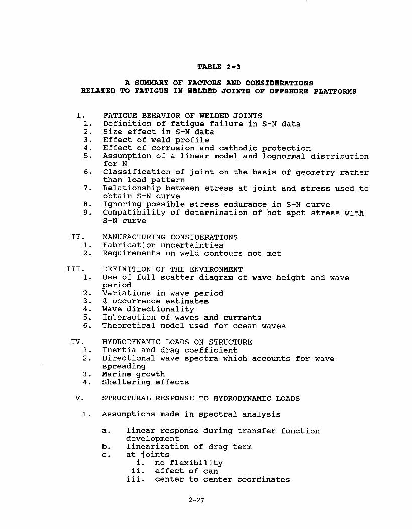
A SUMMARY OFRELATED TO FATIGUE IN
I.1.2.3.4.5.
6.
7.
8.9.
II.1.2.
III.1.
2.3.4.5.6.
IV.1.2.
3.4.
v.
1.
TABLE 2-3
FACTORS AND CONSIDERATIONSWELDED JOINTS OF OFFSHORE PLATFORMS
FATIGUE BEHAVIOR OF WELDED JOINTSDefinition of fatigue failure in S-N dataSize effect in S-N dataEffect of weld profileEffect of corrosion and cathodic protectionAssumption of a linear model and lognormal distributionfor NClassification of joint on the basis of geometry ratherthan load patternRelationship between stress at joint and stress used toobtain S-N cu~eIgnoring possible stress endurance inCompatibility of determination of hotS-N curve
MANUFACTURING CONSIDERATIONSFabrication uncertaintiesRequirements on weld contours not met
DEFINITION OF THE ENVIRONMENT
S-N curvespot stress with
Use of full scatter diagram of wave height and waveperiodVariations in wave period% occurrence estimatesWave directionalityInteraction of waves and currentsTheoretical model used for ocean waves
HYDRODYNAMIC LOADS ON STRUCTUREInertia and drag coefficientDirectional wave spectra which accounts for wavespreadingMarine growthSheltering effects
STRUCTURAL RESPONSE
Assumptions made in
TO HYDRODYNAMIC LOADS
spectral analysis
a. linear response during transfer functiondevelopment
b. linearization of drag termc. at joints
i. no flexibilityii. effect of can
iii. center to center
2-27
coordinates

TABLE 2-3 (continued)
A SUMMARY OF FACTORS AND CONSIDERATIONSRELATED TO FATIGUE IN WELDED JOINTS OF OFFSHORE PLATFORMS
VI.
1.
2.3.
VII.1.2.
3*
VIII.1.2.3.
d. soil stiffness in dynamic modele. damping effects in structural responsef. dynamic response not accounted for in analysis
FATIGUE STRESSES AT JOINT
Method of analysis to evaluate stress concentrationfactors (SCF)Parametric equations used for SCFPoint at intersection where failure occurs
FATIGUE DAMAGE EQUATIONSAssumption of Miner’s RuleAssumption of narrow band damage equation in spectralapproachAssumption of Weibull distribution for stress ranges instress distribution approach
OTHER CONSIDERATIONSErrors by designersBad judgment during towing and installationIn service loads
2-28

These factors should be kept in mind in reading the review ofmultiaxial fatigue prediction approaches. Few have beenaddressed adequately if the intent is to incorporate themultiaxial fatigue approaches in design of welded marinestructures.
As we will present later, there are gains to be made inoverall structural reliability by considering multiaxialeffects if the designer has the proper design tools,information and financial resources to do so.
2.2 CUMULATIVE DAMAGE AND CRACK GROWTH APPROACHES FORPREDICTING FATIGUE RESPONSE
As with stress distributions, it is important to understandexisting fatigue design procedures before reviewing rnultiaxialfatigue research. Most rnultiaxial fatigue approaches areextensions of fatigue life and fracture mechanics approachesdeveloped for uniaxial loading.
The fatigue life of a structural detail is determined by thesum of the elapsed cycles required to initiate a fatigue crackand propagate the crack from subcritical dimensions to acritical size. (Note that the critical crack size andcriteria for failure often differs from one set of data toanother.) The two basic fatigue prediction approaches thatare most widely used in structural design include the Miner’sLinear Rule for fatigue life (crack initiation and growth ofshort cracks) and the fracture mechanics theory for crackgrowth.
Miner’s [2-12] approach is based on knowledge of thestructural loading and the resistance of the structure interms of stress range and number of cycles to failure. Thismethod is developed from test data (S-N curves) together withthe hypothesis, that fatigue damage accumulates linearly.According to this hypothesis, the total fatigue life under avariety of stress ranges is the weighted sum of the individuallives at the various stress ranges, S, as given by the S-Ncu~es, with each being weighted according to the fractionalexposure to that level of stress range. To apply thishypothesis, the long-term distribution of stress range isreplaced by a stress histogram, consisting of a convenientnumber of constant amplitude stress range blocks, S+, and acorresponding number of stress cycles, ql. The constraintagainst fatigue fracture is then expressed in terms of anondimensional damage ratio, q:
2-29

where B = number of stress blocks
v, = number of stress cycles in stress block i
N, = number of cycles to failure at a constantstress range, S,
~L = limit damage ratio
The limit damage ratio q~ depends on the number of cycles ateach stress level.
Theories of crack propagation associated with most crackgrowth methods are based on linear elastic or elastic-plasticfracture mechanics methods.
In linear elastic fracture mechanics, the stress field at thetip of a crack is described in terms of stress intensity witha function of the following form:
where o = gross stress (ksi)
a = crack length (in)
F = geometry correcting factor, dependent uponcrack and part geometry, and stressgradient
K = stress intensity factor
In the literature there exists stress-intensity solutions fora wide variety of crack shapes and loading cases.
The stress intensity is used in all known schemes forcalculating crack-growth rates. For constant-amplitude crackgrowth, it has been shown that crack growth is primarily afunction of AK whereAK = ~., - Kim. That is, da/dn = f(LK).
When constant-amplitude crack-growth rate (da/dn) is plottedagainst LK on log/log paper, an S-shaped tune results as
2-30

shown in Figure 2-20. Traditionally, this curve is brokeninto three regions called Stage I, II and III crack growth.Stage I crack growth, sometimes called threshold crack growth,applies when crack-growth rates are very low. Small changesin AK substantially alter the crack-growth rates. Stage IIcrack growth, sometimes referred to as steady-state crackgrowth, is characterized by a nearly linear relation betweenlog da/dn and log AK, while Stage III crack growth ischaracterized by a rapidly increasing crack-growth rate andresults from crack instability.
Several models have been presented which attempt to describethe relation between da/dn andAK. The simplest, and limitedstrictly to Stage II crack growth, is the Paris equation:
da— =“C(AK)mdn
where C and m are material-dependent constants and aredetermined by experiment. Other relations account for stressratio effects or include Stage I or Stage III crack growth butare modifications of this approach.
Both the fatigue life and fracture mechanics approaches haveeither been applied or proposed for use in marine structuresas described next.
2.2.1 StreSS Concentration Factor (SCF) Amroach in OffshoreStructures
The American Petroleum Institute (API) [2-13] and the AmericanWelding Society (AWS) [2-14] provide a method of evaluatingthe fatigue life of offshore platform tubular joints usingeither an experimental or theoretically determined ‘Ihot-spotstress” range or “hot-spot strain!t range. The hot-spotstress/strain is the maximum stress/strain in a given tubularjoint due to a specified load range, but does not include theItpeaklistress/strain which arises due to the geometricaldiscontinuity at the toe of the fillet welds. The hot-spotstress/strain with this definition can be measured by straingauges (the peak stress/strain cannot be so measured) or itcan be calculated by finite-element analysis; the model usedin the finite-element analysis does not include the filletweld contour or the extremely fine element mesh needed todetermine peak stresses.
2-31

)Kzc FOR
STEEL B
41
SYEEL B
‘JI
I inch= 25.4mm STEEL A
/’
(/II‘TSTEEL A
~;c
— > 1.6x10-’ inchE WY
STEEL B
K:c— < I,6x IO”3 inchE WY
T1 REGION II REGION ~ I REGION ~
I 1
I L- _L-I
STRESS-INTENSITY-FACTOR RANGE,AKZ, LOG SCALE
Figure2-20. SchematicRepresentationof CrackGrowthin Steels
2-32

The AWS Code states that the X-curve is to be used with“greatest total range of worst hot-spot stress or strain onthe outside surface on intersecting members at the toe of theweld joining them -- measured after shakedown in model orprototype connection or calculated with best availabletheoryri.
The British have also developed an approach for predictingfatigue life of welded details and offshore structural joints[2-15]. The non-nodal joints are classified according to weldconfiguration and geometry. The nodal joints are all repre-sented by one S-N curve. Unlike the API code, this approachrecognizes combined stresses and presents data in terms ofprincipal stresses at the weld toe. This approach is based onnominal field stresses and tests of actual joint con-figurations.
During the past twenty years, a substantial amount of work hasbeen conducted and results published on hot-spot stresses insimple tubular joints. This work includes stresses asexperimentally determined by strain gauges on tubular jointmodels; stresses as experimentally determined by photo-elastictubular joint models, and by finite-element analysis oftubular joint models. These results have been used to developcorrelation methods for estimating elastic hot-spot stressesin a wide variety of types and joints and parameters.
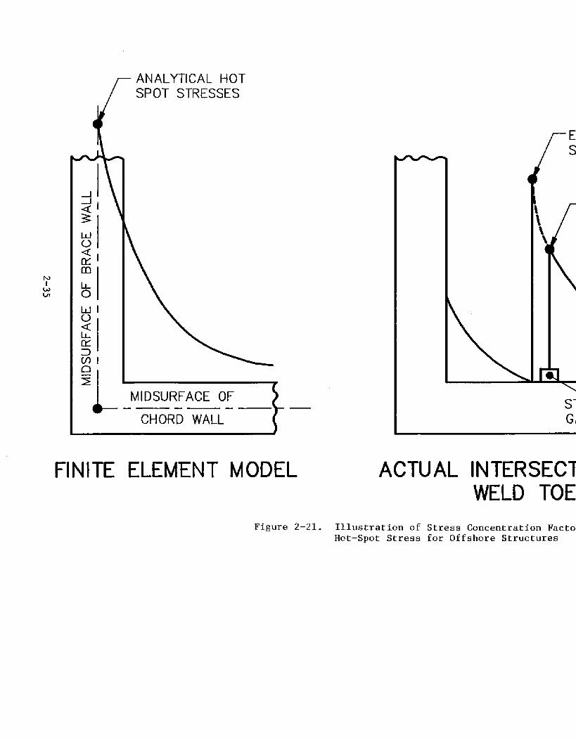
Comparisons between measured hot-spot stresses and finite-element analysis involve considerations of exactly where thehot-spot stresses are located and which type of data is moreappropriate for use with the AWS X-curve. Potvin [2-16]discussed this aspect using the illustration in Figure 2-21.
Potvin et al [2-16] noted that there is a &20% differencebetween their analytical hot-spot stresses and measured hot-spot stresses and they attribute this to the difference in theanalytical and experimental hot-spot locations. Thisvariation in hot-spot location is a result of two factors: theabsence of the weld fillet in their finite element model andthe difficulties involved with obtaining consistentexperimental data. Their finite-element model predicts thatthe hot-spot occurs at the intersection of the midsurface ofthe brace and chord. The inconsistency in the experimentaldata involves the actual location, with respect to the weldtoe, at which the experimental database is obtained. Theexperimental uncertainty is compounded by the size and numberof strain gauges used (i.e., is the gauge small enough to beplaced close to the toe of the weld and/or are there a
2-33

sufficient number of gauges so that an accurate extrapolationof stresses to the toe of the weld is possible as indicated inFigure 2-21).
The test-data available and correlation methods, in additionto being restricted to the elastic regime, are also restrictedin the sense that they are based on “isolated” joints (i.e.,joints in a chord where any other joint is sufficiently faraway so that the two joints are not influenced by each other) .In offshore platforms, quite often two or more joints areplaced at the same axial location on a chord. There are noavailable data on such joints. There are ‘Iruleof thumbttapproaches for joint spacing such that data on isolated jointswould be reasonably applicable.
Correlation methods for joint hot-spot stresses based on jointconfiguration parameters have been developed by a large numberof researchers. These correlation methods include:
1. Marshallts [2-17] presentation of the Kellogg [2-18] ‘equation for hot-spot stresses in the chord and hisequations for hot-spot stresses in the brace;
2. Bijlaard’s [2-19] method for hot-spot stresses inthe chord;
3. Kuang et al [2-20] method for hot-spot stresses;
4. Wordsworth [2-21] for chords;
5. Gibstein [2-22] for chords.
Other authors [2-23 through 2-26] have developed correlationmethods. These correlation methods are developed for in-planejoints as shown by Kuang in Figures 2-14 and 2-15. Gulati[2-7] reviewed several methods mentioned above and comparedthem to finite element analyses, the results of which areshown in the same figures.
The interaction of stress fields of neighboring connections isaccounted for by direct super position of stresses. However,results have been proven suspect in magnitude and location ofhot-spot stress. Additionally, local interaction formulationsare based on parametric formulations and rules of thumb andthese limitations will be discussed in Section 2.3.
2-34
f
ANALYTICAL HOTSPOT STRESSES
m
L!lb-l
n5
LCHORD WALL
MIDSURFACE OF— —
r ES
rE
{
STGA
FINITE ELEMENT MODEL ACTUAL INTERSECTWELD TOE
Figure2–21. Illustrationof StressConcentrationFactoHot-SpotStressfor OffshoreStructures

2.2.2 Proposed Approach for Fatiuue Analysis of ShipStructural Details
While there is no approach specifically written into codes orrules for ship structures (other than empirical stressallowable) , there have been approaches proposed to accountfor fatigue life in ship structural details [2-3, 2-27 through2-29] . The most notable approach is that developed by Munse etal [2-3] and presented in SSC 318. This approach is based oncalculating a “design allowable” stress range, S.dfor fatigue.This stress range is the maximum peak-to-trough stress rangeexpected at the point in question once under the most severesea state and during the entire life of the structure.Comparing that stress range to the allowable stress for otherfailure modes indicates the controlling mode of failure. Inany case, the maximum stress computed from the fatigue designstress range, S.~,must, generally speaking, be less than thenominal permissible stress permitted once by the basic designrules. According to the Munse approach, the design stressrange, Sr~, is found using the following equation:
where Sn = mean value of the constant amplitudestress range at the design life, N~
Rf reliability factor
E = random load factor.
The mean value of the constant amplitude stress range, Sn, isfound by entering the S-N cume of the structural detail ofinterest at the number of cycles expected in the design life,N The probabilistic nature of the design method isi~troduced by the other two factors in the equation.
The reliability factor, R , is meant to account for6uncertainties in the fati ue data, workmanship, fabrication,
use of the equivalent stress range concept, errors in theprediction of load history and errors in the associated stressanalysis. The factor comes from the assumption that fatiguelife is a random variable with a Weibull distribution, and theuse of a relationship for the probability of survival throughN loading cycles. The effect of the reliability factor is toreduce a mean constant stress range to an equivalent stressrange which corresponds to a designated probability ofsurvival greater than the 50% level of the mean stress range.The random load factor, ~, is introduced in the design
2-36
procedure to make possible the use of existing constant-cyclefatigue data in designing for variable loading service condi-tions.
The work of Munse et al represents a significant step forwardin the design of ship structures. It presents the first trulyprobabilistic approach to fatigue design for ship structuraldetails. This approach integrates well with the ship designprocess where a nominal level of stress is developed and nodetail stress calculations are required. Multiaxial stressdistributions are not accounted for within the detail,however, reliability factors are presented which are toaccount for these effects such as scatter about the mean lineof the S-N curve. When detailed stress analysis is warranted,other approaches are required for correlation to the basic S-Ntune for the materials.
2.2.3 Proposed Fracture Mechanics Amroaches for MarineStructures
Thayamballi et al [2-30] proposed a fracture mechanicsapproach for ship structures based on the Paris equationpresented above. This approach takes into account variousfactors influencing fatigue response and reliabilityconsiderations. There are approaches presented to account formultiaxial loading sources and complex stress fields.However, the authors emphasize Mode I stress intensity factorsbeing typical of ship structural loading and fatigue crackgrowth.
Chen used this approach for the fatigue crack growth analysisof the SL-7 hatch corner cracking [2-6]. An integration ofthe Paris eguation and use of the equivalent stress conceptyield the cycles to failure. As described earlier,Thayamballi found that initial crack length is proven a majorconsideration and source of uncertainty.
Fracture mechanics analysis for offshore structures has beenused as a fitness for purpose tool for some time and has beenproposed for fatigue life analysis by Rhee [2-31] and Haung[2-32] among others. Again, the Paris equation for linearelastic fracture mechanics is utilized. The important stepsassociated with the procedure are summarized as follows:
1. calculate storm member forces through frame analysisfor a jacket under a given environment;
2-37

2. determine the crack location for fatigue crackgrowth simulation analyses based on the stressanalysis results and defect distribution status;
3. calculate the stress intensity factors for thefatigue crack growth simulation analyses, and otherfracture parameters required for crack instabilityanalyses. Calibrate the material fatigue andfracture properties required consistently with thefracture parameters;
4. perform fatigue crack growth simulation analyses;
5. perform crack instability analyses to determine thecritical crack size;
6. correlate the results of the fatigue crack growthand crack instability analyses to determine thecomponent fatigue life.
2.3 IMPETUS FOR A MULTIAXIAL FATIGUE APPROACH
Over the past decade, the application of finite elementanalysis to structural details has proliferated, especiallywith the advent of personal computers with memory capacity forfinite element computer programs. Increasing use of this toolhas made it possible to analyze the state of stress in astructural detail to a level of detail beyond that required byexisting nominal stress fatigue design procedures. This toolalso makes it quite possible to predict combined stresses frommultiple loads and from geometric concentrations. Thedesigner now has a choice: 1) to use techniques that he has topredict nominal stresses in joint boundaries and acceptlimitations on consenatism associated with the correlationequations or test data from similar welded components; or 2)cross the nominal stress boundary and predict the state ofstress within the detail. More structural designers for bothships (ABS [2-1] and Columbia Research Corporation (CRC) [2-34]) and offshore platforms (Gulati [2-7] and Rhee [2-31]) arechoosing the latter option. However, the new knowledge hasalso raised additional questions.
Existing S-N curves and crack growth data is typicallypresented from uniaxial tests. Finite element techniquesestimate principal stresses in multiple directions resultingfrom various load and geometric effects. The designer nowrequires additional knowledge on how to characterize the state
2-38

of stress to correlate with uniaxial fatigue life predictionsand improve design reliability.
This situation is evident as a result of a finite elementstudy conducted by Gulati [2-7] for offshore structures. Asshown in Figure 2-18, the principal stress in the neighborhoodof the concentration point at the chord-brace junction of a T-joint subjected to combined loading is not orthogonal to theweld lineal direction assumed by the current fatigue lifeprediction methods. Furthermore, the direction of theprincipal stress changes with the changing magnitudes of theconstituent loadings. The effect of the non-perpendicularityto the weld lineal direction of the principal stress (at the“hot spot”) on the crack trajectory and fatigue life of an aswelded joint is not known.
Because designers are asking increasingly difficult questionson rnultiaxial fatigue response ‘inreal structures, it becamenecessary to review the general multiaxial fatigue researchand those approaches that have been applied to weldedstructural details and evaluate to their applicability tomarine structures.
2-39


3.0 REVIEW OF LITERATURE ON MULTIAXIAL FATIGUE RESEARCH
Interest in problems of metal fatigue and fracture inengineering has a long history dating back well into thelast century. There was certainly an early awareness of theproblem of dealing with the effect of combined loads, butthe major thrust of early fatigue development was in thefield Qf uniaxial fatigue testing and the development ofuniaxial data for material fatigue characteristics in theform of the well-known S-N diagrams. Interest was centeredin the area of long material lives, that is, High CycleFatigue (HCF). In this regime the nominal stresses in thematerial are in the elastic range, only a fraction of theyield stress for the material, and plasticity is confined tothe region in the immediate vicinity of the fatigue cracktip. The discipline of fracture mechanics was not bornuntil after World War I, but it remained until World War IIfor this field to experience really active development [3-1through 3-8]. As understanding of the mechanisms of crackinitiation and growth improved, interest increased in thearea of higher loadings and shorter lives -- that is, theLow Cycle Fatigue (LCF) regime. As the demands oftechnology made clear the need for a more sophisticatedunderstanding of the entire fatigue problem, testingmachines were developed which had the capability of testingin two modes, most often in torsion and axial push-pull,sometimes in torsion and bending, and less frequently inin-plane linear orthogonal loads. Multiaxial fatigueresearch has been active, lively and growing for the pasttwenty-five years, but it is not by any means a maturediscipline. There are a multitude of proposed multiaxialfatigue criteria, the most prominent of which will bediscussed in subsequent sections of this chapter, and thereare codes and formulations (e.g., American Society ofMechanical Engineers (ASME) Pressure Vessel Code) which arein place and may be used on a provisional basis, but theredoes not exist a single unified and validated criterion,accepted by the research community, which can be used forengineering design applications.
In the following sections, the general multiaxial fatigueresearch and candidate approaches to marine structure designand evaluation will be reviewed.
3.1 GENERAL MULTIAXIAL FATIGUE RESEARCH
3.1.1 Fatique Life Estimates for Crack Initiation
The first general category of multiaxial fatigue research isfor those approaches based on the cumulative damage approachfor estimating fatigue life. An equivalent stress is usedto correlate multiaxial stresses or strains to uniaxial test
3-1

data. Each approach is applicable to a specific type offatigue response. Generally, shear stress based criteriaare applicable to fatigue crack initiation in the high cycleregime. Principal stress criteria are applicable to fatiguelife approaches that include crack growth. Combinations ofapproaches have been developed. Approaches have also beendeveloped for estimating fatigue life under low cycleconditions where plastic work dominates. Traditionalinterest had been in long-lived behavior in which nominalstresses in the material remained in the elastic range wellbelow the tensile yield stress. Figure 3-1 taken fromReference [3-8] illustrates schematically the partitionbetween low cycle fatigue and high cycle fatigue regimes.The differentiation between high cycle and low cycle is im-portant in further categorizing multiaxial fatigueapproaches.
In the following sections the general multiaxial fatigueresearch developed for applications in other industries suchas pressure vessels, aircraft, moving vehicles and heavyequipment is reviewed. Much of this research is based onextension of existing uniaxial research with newerapproaches based on plastic work estimates.
3.1.1.1 Stress Based Criteria
Early research in multiaxial fatigue was, quite naturally,an extension of uniaxial work and dealt with combinedstresses in the HCF regime. The work of Mason [3-9] andMason and Delaney [3-10] is representative.
Two well-known and widely used yield criteria, thoseattributed to Tresca and to Von Mises were adapted early tocyclic stresses.
Tresca: TMax = (al-a,)/2= constant
Von Mises: roctahedral = 1/3[(al-a,)’+ (a,-U,)’
L
1
1/2+ (a3-a1)2 = constant
where al > up 2 Ua are the principal stress and the value ofthe constant is specified for a given fatigue life.
A significant contribution was made byin the mid-30’s through the early-50’sGough found that the arc of an ellipseto his experimental data from in-phasetests of brittle materials and ductile
3-2
Gough and colleagues[3-11 through 3-14).provided a good fitbending and torsionmaterials. Guest

I
I
103 104 I 105 106
10–20,000CYCLES
FATIGUE LIFE IN LOG N CYCLES
107
Figure3–1. SchematiclZepresentationof High Cycle and Low Cycle Fatiguas a Functionof StrainStateand StrainAmplitude

[3-15, 3-16] noted that Gough’s empirical formulations couldbe reduced to a single expression:
al-a2 al+u~+ k = constant (3-1)
2 2
where al > a2 2 as are principal stresses and k is a measureof the relative ductility or brittleness of the material.Guestis relationship is a statement that constant fatiguelives are a function of the maximum shear stress, (al-az)/2,modified by a fraction, k, of the normal stress on the planeof maximum shear stress, (al+aa)/2. Variations of thistheme in terms of both stress and strain will be seen tooccur repeatedly in the following years. Tipton and Nelson[3-17] have expressed the Guest criteria for combined in-phase bending and torsion as:
t-[; ~=+ [;-) .] (3-2)
where D = amplitude of cyclic bending stress
T = amplitude of cyclic torsion shear stress
bn = fatigue limit for notched specimens inbending (determined experimentally)
t“ = fatigue limit for notched specimens intorsion (determined experimentally)
Figure 3-2, taken from Reference [3-17], shows an excellentcorrelation of data taken from multiaxial notched specimentests in torsion and bending with the torsion-bendingfatigue limit predicted by (3-2) above. Also shown inFigure 3-2 are fatigue life predictions using the well-knownVon M&.es distortion energy yield criteria applied toconstant-amplitude bending and torsional stresses. Stressesin the notch of the specimen have been calculated in twoways: (1) using elastic stress concentration factors, K,;and (2) experimentally determined stress concentrationfactors, Kr. In this case, using the elastic stress concen-tration factors gives a very poor correlation. Other casesdisplayed in [3-17] using & are in better agreement. K,predictions are generally better, but in most casesunconsenative. Further confirmation of the form of theGuest Law was provided by Findley [3-18]. McDiarmid [3-20]also proposed a criterion for fatigue failure based on thecritical ranae of shear stress modified.by the normal stressacting on the plane of maximum shear stress. Sines [3-19]proposed a tensorial method of combining biaxial alternating
3-4

DIFFERENT R VALUESuSED IN TESTS
b
25.4 R
I
—Y
znE
7,6 mm
y 150 -%- ._.
‘x, -.u-n ,P.;”L.,
a
55”? GuEST ~> ‘\Ia \z 100 \<
‘:;’”4
VON MISES-Kf
u-lmw
\\ “1,
mi,’,
k
~5:1-150 200
SENDING STRE5S AMPLITUDE, u(MP1]
Figure3-2. Comparisonof PredictedCombinedBending-TorsionFatigueLimitwith Test Data for a CircumferentiallyNotchedRound-BarSpecimen[3-17]
3-5

(in-phase) stresses with a static mean stress. The methodis general in nature and could be extended to triaxialstress systems with a superimposed static stress.
Langer [3-21] has discussed the application of TrescaJscriterion to the design of pressure vessels involvingmultiaxial fatigue. Trescals criterion was favored over VonMises’ “criterion” because of its simplicity, conservatismand adaptability to more situations. This particularcriterion was adopted as the basis for evaluating multiaxialfatigue in the ASME Boiler and Pressure Vessel Codeprocedures [3-22]. The approach is as follows:
s =alt the value of (1/2)(SlD-S3D) maximizedwith respect to the least and greatestprincipal stress values of the stresscycle where SID and S3D are the maximumand minimum stresses respectively.
The parameter S.,,is called ‘Istress-intensityrrwhich is usedas the parameter correlating fatigue life (to crackinitiation) . It is the maximum range (over the completeIlcycle!!of loading) of shear stress acting on a particularpair of planes and in a particular direction; its absolutevalue is important and not the planes and directions alongwhich it acts. This is a stress based criterion. Thisapproach has been refuted under out-of-phase multiaxialloading because of the path independence assumption.
Reviews of the ASME Boiler and Pressure Vessel Code exist[3-23, 3-24] indicating mixed results for out-of-phaseloading. In the case of biaxial in-phase constant amplitudeloadings, the principal stresses will act in a constantdirection, but with oscillating amplitudes. The out-of-phase monofrequency constant amplitude problem is much morerealistic for many rotating machinery and pressure vesselapplications. Note that most of the following equivalentstress approaches are presented in a format in whichsinusoidal loading functions are known, for example, inapplications such as rotating machinery.
More recently, ASME adopted the following formulation in the1974 ASME Boiler and Pressure Vessel Code [3-25] for anequivalent stress, SALT (S.lt)which for fully-reversedbending and torsion can be expressed as:
3-6
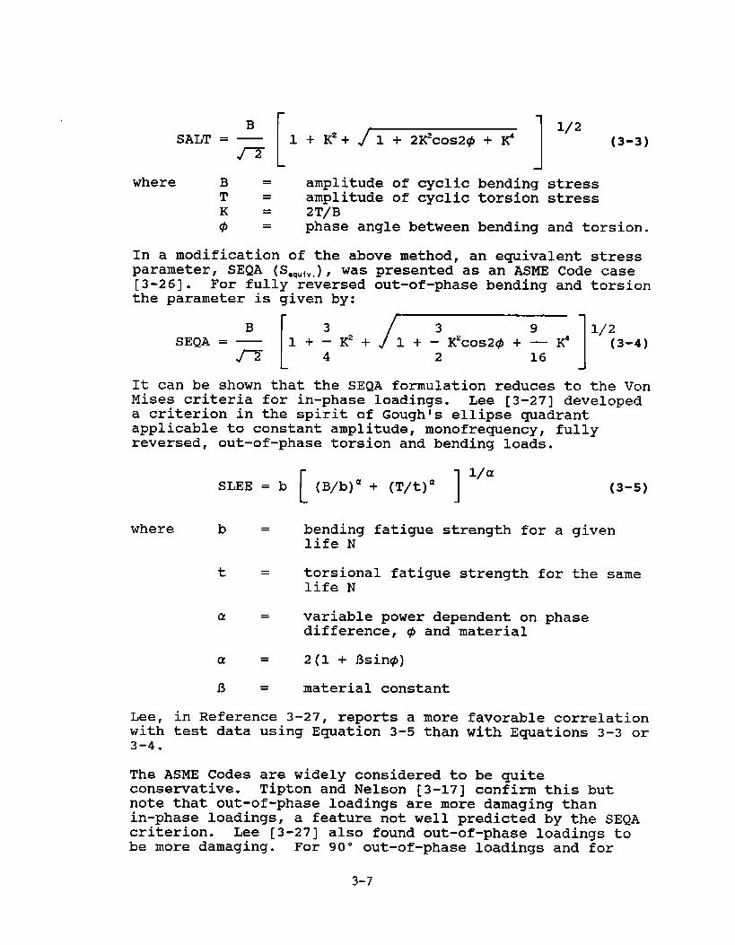
B
fl[
1+K2+ 11/2SALT = — 1 + 2K2cos2@ + K’ (3-3)
where B = amplitude of cyclic bending stressT = amplitude of cyclic torsion stress
= 2T/B; = phase angle between bending and torsion.
In a modification of the above method, an equivalent stressparameter, SEQA (S.,U,V.),was[3-26]. For fully reversedthe parameter is given by:
B r 3SEQA = — 1+–K’+
n 4L
presented-as an-ASME Code caseout-of-phase bending and torsion
3 9 11/2l+– K2cos2@ + — K’ (3-4)2 16
It can be shown that the SEQA formulation reduces to the VonMises criteria for in-phase loadings. Lee [3-27] developeda criterion in the spirit of Goughls ellipse quadrantapplicable to constant amplitude, monofrequency, fullyreversed, out-of-phase torsion and bending loads.
[ 1I/a
SLEE = b (B/b)a + (T/t)d (3-5)
where b = bending fatigue strength for a givenlife N
t = torsional fatigue strength for the samelife N
a = variable power dependent on phasedifference, @ and material
a = 2(1 + fisin@)
f3 = material constant
Lee, in Reference 3-27, reports a more favorable correlationwith test data using Equation 3-5 than with Equations 3-3 or3-4.
The ASME Codes are widely considered to be quiteconsemative. Tipton and Nelson [3-17] confirm this butnote that out-of-phase loadings are more damaging thanin-phase loadings, a feature not well predicted by the SEQAcriterion. Lee [3-27] also found out-of-phase loadings tobe more damaging. For 90° out-of-phase loadings and for
3-7
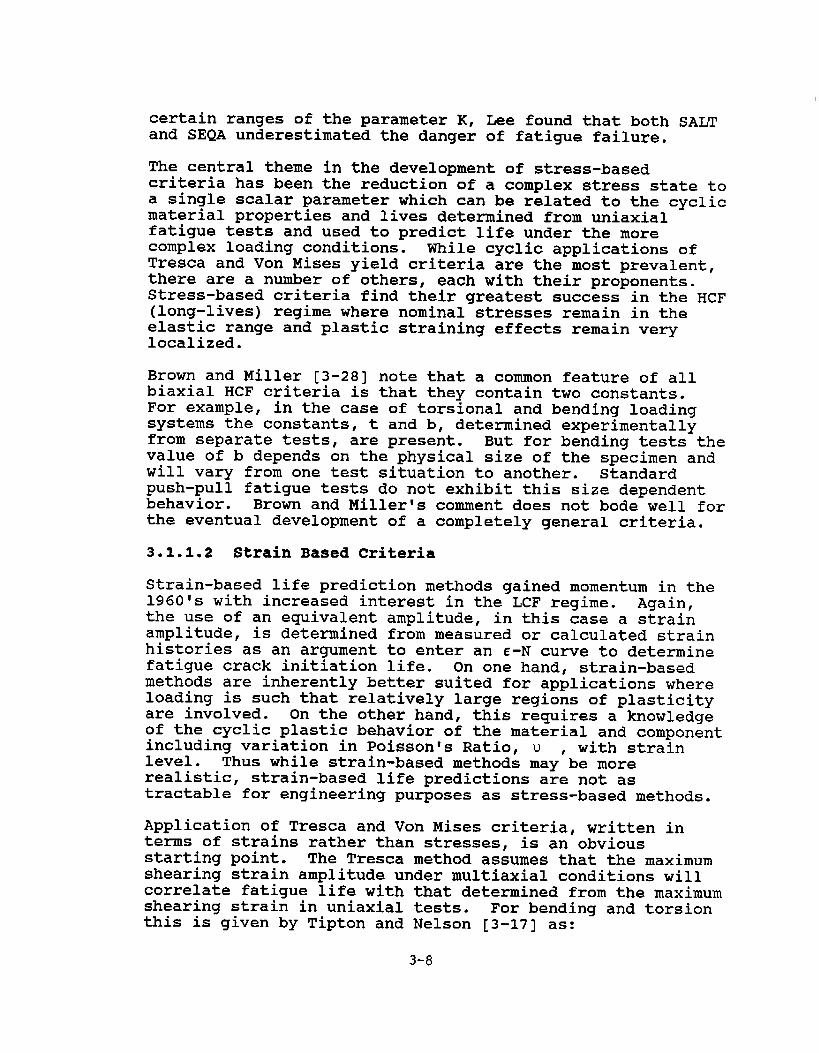
certain ranges of the parameter K, Lee found that both SALTand SEQA underestimated the danger of fatigue failure.
The central theme in the development of stress-basedcriteria has been the reduction of a complex stress state toa single scalar parameter which can be related to the cyclicmaterial properties and lives determined from uniaxialfatigue tests and used to predict life under the morecomplex loading conditions. While cyclic applications ofTresca and Von Mises yield criteria are the most prevalent,there are a number of others, each with their proponents.Stress-based criteria find their greatest success in the HCF(long-lives) regime where nominal stresses remain in theelastic range and plastic straining effects remain verylocalized.
Brown and Miller [3-28] note that a common feature of allbiaxial HCF criteria is that they contain two constants.For example, in the case of torsional and bending loadingsystems the constants, t and b, determined experimentallyfrom separate tests, are present. But for bending tests thevalue of b depends on the physical size of the specimen andwill vary from one test situation to another. Standardpush-pull fatigue tests do not exhibit this size dependentbehavior. Brown and Millerls comment does not bode well forthe eventual development of a completely general criteria.
3.1.1.2 Strain Based Criteria
Strain-based life prediction methods gained momentum in the1960!s with increased interest in the LCF regime. Again,the use of an equivalent amplitude, in this case a strainamplitude, is determined from measured or calculated strainhistories as an argument to enter an E-N curve to determinefatigue crack initiation life. On one hand, strain-basedmethods are inherently better suited for applications whereloading is such that relatively large regions of plasticityare involved. On the other hand, this requires a knowledgeof the cyclic plastic behavior of the material and componentincluding variation in Poisson’s Ratio, u , with strainlevel. Thus while strain-based methods may be morerealistic, strain-based life predictions are not astractable for engineering purposes as stress-based methods.
Application of Tresca and Von Mises criteria, written interms of strains rather than stresses, is an obviousstarting point. The Tresca method assumes that the maximumshearing strain amplitude under multiaxial conditions willcorrelate fatigue life with that determined from the maximumshearing strain in uniaxial tests. For bending and torsionthis is given by Tipton and Nelson [3-17] as:
3-8

[ 11/2Y =
max E*xx
(1+ )2 + .,’ (in-phase loading)
{ }
YXYmax = greater of
Exx (l+U)
where Y =XY torsional shear
(90° out-of-phaseloadings)
strain amplitude
E =xx bending strain amplitude
u = PoissonIs Ratio
The equivalent strain amplitude is given by:
E, = .aJ(l+u)
In the case of a standard SAE uniaxial bending-torsionfatigue specimen, the fatigue strain life for a normalized1045 steel is given by Tipton and Nelson as:
En = 0.00481(2N~)-0”102-1-0.182(2N~)-0”433
where E* = strain amplitude
2Nt = cyclic reversals to failure (tworeversals per cycle)
Results are shown in Figures 3-3 through 3-5.
Note that the coefficients and exponents in the aboveequation, known as the listrain-lifetlequation, are material-specific and at this time are available for only a limitednumber of materials.
Tipton and Nelson have also evaluated a Von Mises strain-based ap~roach under assumptions of ~yy= -UEXX, Figure 3-4,andu =u, Figure 3-5, where~ is a variable Poisson’s Ratiocalculated by Gonyeais method [3-29]. The effective strainused for entering the uniaxial 6-N curve is given by:
1
[ 11/2
‘=/=7=)
(E,-E,)2 + (E2-E3)2 + (E3-E,)2
where El, E2, E3 are principal strain amplitudes and u isPoissonts Ratio = .29 or .50.
Tipton and Nelson comment on several problems that arecharacteristic of fatigue testing. First, there is not a
3-9

TRESCA EQUIVALENT~RAIN
Figure3–3. Comparisonof Life PredictionsBased on the TrescaEquivalentStrainCriterionwith SAE Test Data [3-17]
IN-PHASE VON MISES STRAIN;E}”}”=-lJI:YX
107 .V q--.-,==.. ~. -T–r..,.T7.–r
-5,/
,///%3 ‘X3
.-,06
9/T
‘;’ T ~,$“(#~l’T,. q) ~
x,-~ B’x~W@.
T z
, ~5
~ wO:/Q,,,/z
: //
?’
~ -3B
~~~~~~~~ A
,/’”2 ~-p.reb,nding, ~4
B T-purr tor?ion
y~
h— B-T
zY— B=zT
T2- T=2B
,03 -J-. ,U,.3 ,04 , ~5 , Ofi I o’
N observed (Cyc5.)
O dc”otes V= OS, otherwise u=0,z9
Figure3-4. Comparisonof Life PredictionsBasedon the Von Mises EquivalentStrainCriterionwith In-PhaseSAE Test Data, TakingcircumferentialNotch Strainas Poisson’sRatio timesNotch BendingStrain [3-17]
3-1o

IN-PHASE VON MIWS STRAIN;u = v
‘“’F’- ‘ .2=7-. -T. ~.. ~- -,. ---
,.6
I
/
1-//;;.4 +-
L< .,,N T ~ }
/
,.’,05 Y
YB R,/’’;:/” ,
,
{
;,og:,, ;7,,,,,]
, ‘4 , ~11 I o’
N observed (CycS.)
Figure3-5. Comparisonof Life PredictionsBased on the von Mises EquivalentStrainCriterionwith In-PhaseSAE Test Data, Usinga VariablePoisson’sRatio [3-17]
Figure3-6. ActualversusPredictedLives:MaximumPrincipalStrainTheory [3-8]
3-11

commonly accepted standard for the size of a crack thatconstitutes initiation. A crack detectable by visualinspection is one definition. In other cases, opticalmicroscopes are used or ultrasonic acoustic transducers maybe employed. O.lmm and lmm crack lengths are otherdefinitions which are used. “Life” may be life to crackinitiation, or life to failure which may be defined as apercentage drop in load-carrying capability. Ten percent,twenty percent and one hundred percent drop-offs are oftenused. Tipton and Nelson use a fifty percent drop-off inReference [3-17].
A further difficulty in using uniaxial data is that,depending on the loading modes, their relative amplitudesand the multiaxial strain state, the type of crackingexperienced by a multiaxial specimen may be quite differentthan that experienced by the uniaxial specimen under“equivalent” conditions.
It may well be that application of equivalent uniaxial datato predict multiaxial fatigue phenomena will be, at best, aninterim procedure which will be useful until more generalmultiaxial criteria are developed together with specificallyapplicable supporting material data.
The use of a constant value for Poisson’s Ratio is also aproblem which must be dealt with when large plasticity orhigh temperatures are present. Gonyea [3-29] has proposedan iterative method for determining a variable value forPoissonis Ratio.
Brown and Miller [3-30 through 3-32] have presented animportant strain-based multiaxial fatigue life criterionwhich is a natural extension of Guest’s earlier work. Theapproach is one of several known as “critical planellmethods. It assumes that initiation is dominated by theamplitude of the maximum shear strain, Y ~,,,and thatpropagation is strongly influenced by the strain, En, normalto the plane on which Ym,Xis acting, a plane which theycalled the T-plane. The general form of the criterion theyrecommended formed a family of ellipses with life as aparameter.
(y:)’+(’)’ ‘1
The specific application is to strain-controlled in-phasecombined tension and torsion tests, with experimentallydetermined values of g, h and j which were found to varywith life. Figure 3-6 shows these results.
3-12

Fash et al [3-8] conducted experiments on a thin-walled tubespecimen in tension-torsion and on a solid notched shaft inbending-torsion and compared results with predictions basedon five
1.
2.
3.
4.
5.
different theories. They concluded that:
maximum principal multiaxial strain correlateslife with maximum principal uniaxial strain(Figure 3-6);
the effective strain (Von Mises) may be used toobtain life from uniaxial data (Figure 3-7) ;
maximum multiaxial shear strain may be correlatedby converting uniaxial data into shear strains(Tresca method) (Figure 3-8);
a theory proposed by Lohr and Ellison [3-33] isbased on the maximum shear strain,Y , which occurson a “critical plane” which in the case oftension-torsion loading of thin-walled tubesoccurs on planes intersection the surface at 45°.The maximum shear strain range, Y , is modifiedby a fraction of the strain normal to the criticalplanes, En (F@ure 3-9);
a theory proposed by Kandil, Brown and Miller r3-34], essentially an-extension of the earlier B~ownand Miller work [3-31, 3-32], is similar inappearance to that of Lohr-Ellison but the methodsdiffer in the definition of the shear strain andnormal strain components (Figure 3-10) . Lohr andEllison and Kandil, Brown and Miller approachesyield essentially equivalent correlations of thin-walled tube specimen fatigue life.
The relationship between fatigue life and a~~lied strainamplitude for uniaxial tests is given by the strain-lifeecil ation:
where A~
of f
Ef ‘
b
c
Ac af ‘—=— (2Nj)b + Ef’ (2Nf)c2 E
= axial strain range
= fatigue strength coefficient
= fatigue ductility coefficient
= fatigue strength exponent
= fatigue ductility exponent
3-13

Figure3-7. ActualversusPredictedLives:EffectiveStrainTheory [3-8]
~ ‘ L--u/$’”*m
Moxmum Sheer SrrO,n
.c Ir~
v
i,
20 0 O@ TensSonv 35
Figure3–8. ActualversusPredictedLives:MaximumShearStrainTheory [3-8]

Figure3-9. ActualversusPredictedLives:Lohr and EllisonTheory [3-8]
D’ I !
‘d‘- :Kandll. Brwn - M,ller
Pororwer
Iylc
000 Tens,onv 05A 100 20❑ rn TWSIOn
I
Figure3-10. ActualversusPredictedLives:Kandil,Brownand MillerTheory [3-8]
3-15

E = Youngls Modulus
Nf = cycles to failure
2Nf = reversals to failure.
Multiaxial strains as determined in the above theories areequated to the strain life equation above with coefficientsand exponents appropriate to the material. For the work ofFash et al, failure was defined as a 10% load drop-off forthe thin-walled tube tests and the occurrence of a 1 mmcrack for the notched shaft specimen tests.
In the uniaxial test the maximum principal strain andamplitude is equal to the applied axial strain amplitude.Life estimates based on the rancreof maximum principalstrain are based on a similar form of the strain-lifeequation:
AE’ of’—= — (2N~)b+ E/ (2Nt)c2 E
where AE ‘ is the range of maximum strain.
Effective (Von Mises) strains are given by:
then
2
[ 1 1/2T=– (E1-E2)2 + (E2-E3)2 + (E1-E3)23
For uniaxial data:
Ay ma. AE= (l+U) —
2 2
For multiaxial loadings, the maximum shear strain fromMohr’s circle is:
(U=.5)
AYnlax
= A (E1-ES) (El 2 E, 2 E,)2
3-16

Substitution ofU=.3 and u=.5 for elastic and plastic valuesof Poisson’s Ratio gives the maximum shearinq strain(Tresca) criterion:
*Y mm% afI— = 1.30 — (2Nt)b+ 1.50 E~t(2Nf)c
2 E
For the Lohr and Ellison criterion:
AY*
— = A (E1-~,)2
where the asterisk is used to designate the Lohr and Ellisonparameters, substituting appropriate values of PoissontsRatio gives the Lohr and Ellison form of the strain-lifeequation.
AY*— + .4 En = 1.44 (2Nt)b-I-1.60 ~f (2Nt)c2
The Kandil, Brown and Miller criterion differs in thedefinition of En and adds a term modifying the maximum shearstrain range,A~ max.
Substituting appropriate values of PoissonIs Ratio yieldsthe Kandil, Brown and Miller variant of the strain-lifeequation.
A-Y“x of t
+ k~n = 1.65 — (2Nf)b + 1.75 Ef’(2Nf)c2 E
A comparison of actual lives versus the predicted lives bythe five theories is shown for the smooth thin-walled tubetests in Figures 3-6 through 3-10. Correlation for all fivemethods falls within a scatter band of three of the perfectcorrelation line, except for the torsion data which isattributed by the authors to anistropy measured in the 1045steel specimens. The Lohr and Ellison theory appears to
3-17

give the slightly better results but not enough to justifyany strong preferences.
The results for the notched specimen tests are shown in theFash et al paper but are not included here. Correlationsbased on all five theories were rather poor andunconsenative showing that there is still much tounderstand about the effect of stress concentrations innotches.
At this point it appears that the Kandil, Brown and Millerapproach and the Lohr and Ellison approach are emerging atthe head of the pack in multiaxial fatigue theories, thusthe emphasis placed in the preceding paragraphs. Leese [3-35] in a recent state-of-the-art review, shows thedifference in the critical planes assumed in the twotheories on a Mohr’s circle representation of thethree-dimensional strain state, Figure 3-11. Qualitatively,the difference between the two theories is that Lohr andEllison reflect tendencies for the crack to be driventhrough the specimen whereas the Kandil, Brown and Millerapproach reflects the strains which drive surface cracking.
Socie, Waill and Dittmer [3-36] conducted standard uniaxialtests using Inconel 718 specimens and biaxialstrain-controlled tests under: (a) axial loading only; (b)torsional loading only: and (c) combined axial and torsionalloading. Results of the uniaxial tests are given in Figure3-12 for three different criteria for failure: occurrenceof a crack O.lmm long, occurrence of a crack l.Omm long, andseparation of the specimen. For this material, strain atthe .lmm crack level was 15% of that at separation, whilestrain at the l.Omm crack was 90% of that at separation.Socie et al also examined modifications to the Lohr andEllison parameter and to the Kandil, Brown and Millerparameter for the effect of mean stress, an importantconsideration in ship fatigue. Both modified theories gavereasonably good correlations, but Lohr and Ellison wasslightly the better. The comparison is shown in Figure3-13. The constants in the Lohr and Ellison equation may beobtained from uniaxial tests.
Brown and Miller [3-37] have identified two distinctcracking systems which they define as Case A and Case B,each of which gives rise to different fatigue lives. Thetwo cases are depicted schematically in Figure 3-14. InCase A, strains El and ~a are parallel to the surface (as inthe case of combined tension and torsion) and tend togenerate shallow surface cracks. Under other loadings ~a isnormal to the surface tending to drive deep cracks. This isindicated in Case B. Different functions were proposed foreach case.
3-18
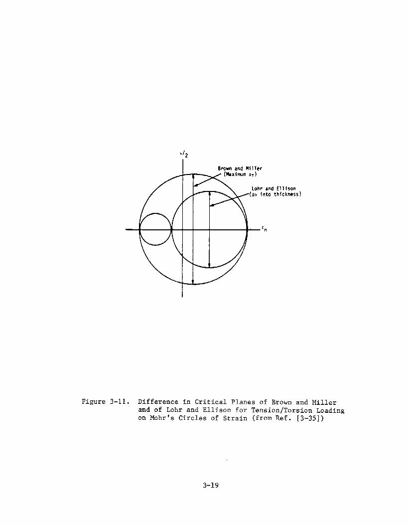
Y12
I BrowrI andM{1l“er
‘n
Figure3-11. Differencein CriticalPlanesof Brownand Millerand of Lohr and Ellisonfor Tension/TorsionLoadingon Mohr’sCirclesof Strain (fromRef. [3–35])
3-19

0010
0.009
0.008
0.007
0.006
0.005u
0.004
0.003
102 Id m’ K? 10’Cyclm to Failure, Nf
Figure3-12. UniaxialTest Resultsfrom Solid Specimens
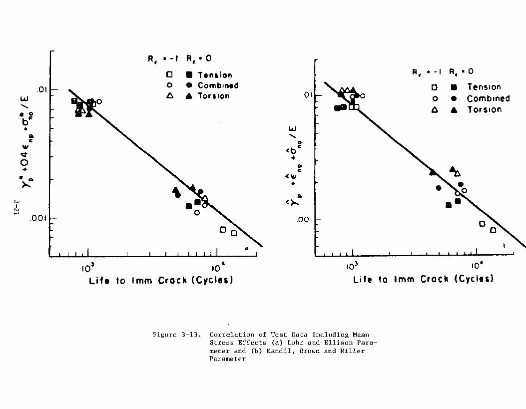
%-l R*BC)
0 ● ~ontion
o ● Comb~nodA A Tortion
w\
o<bc
+
,001
Id 10’
Life to Irnrrl crock (Cychd
Figure3–13. Correlationof Test Data IncludingMeanSLressEffects (a) Lohr and EllisonPara-meter and (b) Kandil,Brown and MillerParameter

-NCIPAL STRAINS PLA~ ot= MAXIMUM SHEARE1>EZ>E3 STRAN Am ~CTION OF
STAGE I CRACK GROWTH
●LANE 4 DWECT~NOP S7E n
CRACK GmwTH
m
Figure 3-14. Stage I and StageII CrackGrowrhSystemsUnder GeneralMultiaxialCyclicStrains
3-22

Other authors also have made contributions in the area ofmultiaxial strain-based methods. Konter, Janssen andHusslage [3-38] have presented a quadratic method forequivalent strain range using plastic strain components:
E●q2 = (16-9J3) ~.z+ B (y ~~2)2
Different values of the constant, B, apply to Cases A and B.Zamrik and Frishmuth [3-39] proposed use of maximum totalstrain to correlate out-of-phase fully reversed bending-torsion tests:
Grubsic and Simburger [3-24] proposed examining all planesin a body and selecting the most unfavorable combination ofmean and alternating shear stress on each plane as the basisfor a life criterion.
3.1.1.3 Plastic Work Methods
The difficulties associated with extending stress-based orstrain-based criteria to the more general cases ofcumulative damage under random loadings of mixed frequencyand phase has led a number of investigators to considermethods in which the material’s resistance to fatigue undermultiaxial loading conditions can be related to the workexpended in each stress-strain cycle. Early foundations forenergy approaches were laid by Feltner and Morrow [3-40],Morrow [3-41] and Halford [3-42) during the 19601s. In1977, Leis [3-43] proposed a damage parameter utilizingstrain energy per”cycle which was intended to account formultiaxiality of stress and stain, mean stress, and viscousdeformation response. The method assumed isothermal stress-strain cycles of constant strain amplitude obtained fromuniaxial tests. Using existing published data, Leisobtained an excellent data collapse for uniaxial data usinga log energy versus a log life plot, but the collapse ofbiaxial data was much less impressive. Leist definition offailure was the termination of Stage I crack growth. In1981, Garud [3-44] proposed an energy method, again based onevaluation of the plastic work per strain cycle, but nowintroducing a modified strain hardening method into thestress-strain constitutive relations for the material.Garud used the axial-torsional data of Kanazawa, Miller andBrown [3-45] to correlate his results. Figure 3-15 showsthe uniaxial stress-strain curve used to determine theplastic work per cycle. Figure 3-16 shows log plasticenergy versus log life for the various tests in the Kanazawadata. Note that the axial test data falls on the lowerbound and torsional data falls on the upper bound of afactor-of-three scatter band with the phase angle biaxial
3-23

o 0.5 1.0 1.5 2.0 2.5 3,0
AxialStrainAmphtude@fCent)
Figure3-15. UniaxialStress-StrainApproximationfor 1 PercentCR-MO-VSteel (segments4, 5 and 6 extrapolated;segments5 and 6 not shown)
3-24

@ Tcmion49 kid
AO
L \
1. 1 i 1 111111 I 1 1 111%lam
Me to Failure.N (cycles)
Figure3-16. PlasticWork Per Cycle (Calculated)VersusLife to Failure(Observed)
3-25

tests generally falling in between. When a weighing factorof % was applied to the plastic work done by the shearstraining, the correlation improved as shown in Figure 3-17.The effect of phase angle is shown in Figure 3-18. At thehigher axial strains (above the point C), the 90” out-of-phase loading absorbs the most plastic work, confirming thefindings of other investigators that this condition is themost damaging for this type of loading. Garud states thathydrostatic stress and mean stress effects may be includedin the method; however, strain rate and creep effects areexcluded.
Ellyin and his colleagues [3-46 through 3-49] have alsoworked on the development of energy based multiaxial fatiguecriteria throughout the 19801s. The criterion proposed inEllyinis recent paper, Reference 3-49, is based on thetheory that the damage caused as a result of cyclic loadingis a function of the mechanical work input to the material.The total work per cycle, AWt, is partitioned into elastic,w*, and plastic, 4WP, components with separate formulationsfor each. The elastic and plastic components are depictedgraphically for a uniaxial cyclic loading case in Figure3-19. The Ellyin criterion includes the effect ofhydrostatic pressure and mean stress but in its present formis limited to proportional or nearly proportional loadingsin the biaxial mode. This implies that the principalstresses are nearly constant in direction through the cycle.Experimental results for two strain ratios are required todetermine the constants in Ellyin’s equation; however, thesecould be determined from relatively simple tests such as astandard uniaxial push-pull fatigue test and a simpletorsion fatigue test. Results of such tests are generallyavailable for a wide range of materials. Ellyin and Goloshave applied the criterion to correlate test data obtainedfrom thin-walled tube tests with alternating internalpressure. Results for four different strain ratios areshown in Figure 3-20.
Plastic strain energy methods have great appeal because oftheir intrinsic flexibility. However, there are practicalconsiderations. They are basically better suited for theLCF regime where high straining is present. For the HCFregime where straining levels are much lower, the amount ofplastic work is low and much more difficult to quantify. Anassumption present in plastic work methods is that, afterthe first few cycles of straining, the constitutiverelationships remain constant. For materials or underloading conditions for which this assumption is lessrealistic, the method would be much more complex. A summaryof the multiaxial fatigue life approaches is presented inTable 3-1.
3-26

I 1 \
I 1 1 I I 11111 1 1 1 111~lm
Life to Failure, N (cycles)
Figure3-17. PlasticWork Per Cycle (Calculatedwith aWeighingFactoron ShearWork) versusLifeto Failure(Observed)
3-27

0
0 W outd-phase (F,+ y.)O h-phase (E, + y,)
O Torsional(7, = 1.5,,)A kat (CJ
.
/—
c
0.05 01 015 0.2Axial Strain &nplltude.Em@rcent)
Figure3-18. In-Phasevs. Out-of-PhaseStraining(Comparison)
3-28

Au~+clm
I
AV@=bw~ + AWe
/AWe
AWP
Figure3-19. Elasticand PlasticStrainEnergyDensitiesfora UniaxialCyclicLoadingCase
3-29
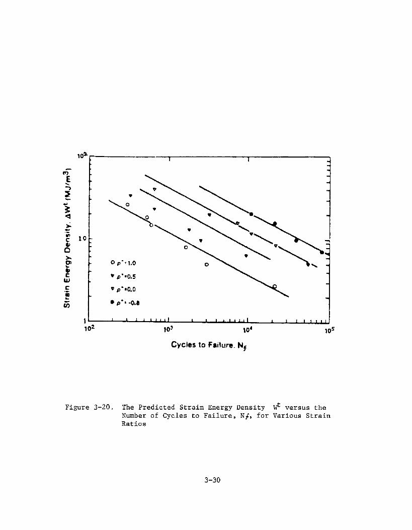
10It
II 1 1 1 1 1 1 1 1 I 1 I 1 1 1 1 1 1 1 A 1 1 1 1 1 1 J102 ,03 104 10s
Cycles IO Failure. Nf
Figure3-20, The PredictedStrainEnergyDensity Wt versustheNumberof Cyclesto Failure,N+, for VariousStrainRatios
3-30

TABLE 3-1
APPLI CABLE MAF APPROACHES
Ecwiva[ent Stress Methods
I. Von Hises methods
[[. Tresca methods
111. Guest method
yLJP
Strain-based methods
IV. Maximrnshearstrain nwthoti
v. Effective strain method
VI. Haximun principal strain
SlM4ARY OF WLT I AX[ AL FATIGUE APPROACHESF~ PIIEOI CT[ NGFATI GUE LIFE BASEO U CIR?JLATlVE OAMAGEAPPROACtlES
T octahedral = 1/3 (( U,-UZ)2 +h
(u,-%)’ + (U,-u, )’) = constant
7m, = a, -u$2 = constant
(7,-02 O,+fq
—k — = constant2 2
ca =AMSXI(I +u)
I
c[= j--, (El-a’
REf4ARKS
Biaxial von Hises stress correlatesuith uniaxial von Mises stress atfai lure. Applicable to HCF regime.
Biaxial Tresca stress correlateswith uniaxia[ Tresca stress atfai~ure. App[ icabte to liCF regime.
Haxinnnn shear streaa mdified by afrsction of norms[ atress awl itdepredicted using uniaxial fatiguelimits. Appt icable to liCF regime.
Maxinun biaxial shear strain iscorrelated uith maxim shearstrain in uniaxial tests.Applicable to LCF and HCF regimes.
von Hises strain in biaxial testsis correlated uith von Hises atrainin uniaxial tast. App[ icable toLCF ard HcF regimes.
Maximun principal strain underbiaxia~ conditions correlates uithmaximn principa[ strain inuniaxiai test. App[ icabie to LCFand IICF regimes.
REF
3-17
3-1?
3-11
3-
3-a,
3-8,
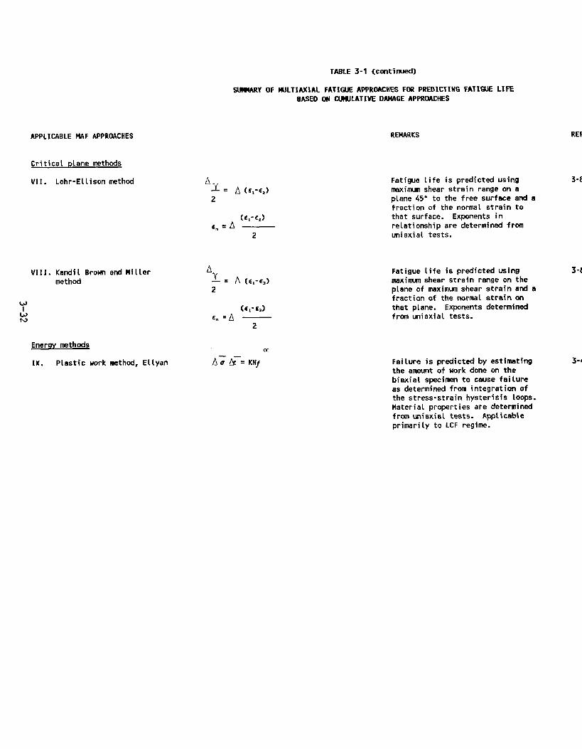
TAGLE 3-1 (cmtinud)
APPLI CABLE MAF APPROACHES
Critical plane methods
VII. Lohr-Ellison method
VIII.Kandi L Brown and Millermethod
Enerqy msthods
IK. Piastic work methti, E[Lyan
SLM4ARYOF ~LTIA%lAL FATIUJE APPROACHESFM PREDICTING FATIGL!& LIFEBASED ON CIMJLATIVE DAMAGEAPPROACHES
Ay= A(E,-E,)2
(6,-EJ~m=A —
2
REMARKS
Fatigue tife is predicted usingmmimum shear str~in range on aplane 45° to the free surface ad afraction of the normal strain tothat surface. Exponents inrelationship are determined fromuniaxiat tests.
FatigueLifeis predicted usingmaximum shear strain range on theplane of maxim-m shear strain ami af ract ion of the norms 1 strain onthat plane. Exponents cfetermi nedfrcsn uniaxial tests.
Fai Lure is predicted by estimatingthe amount of workdoneon thebiaxial specimen to cause fai (ureasdetermined from integration ofthe stress-strain hysteresis LOOPS.Material properties are determinedfrcm uniaxisl tests. A@ i cableprimarily to LCF regime.
REF
3-8,
3-8,
3-44

3.1.2 Fatiuu e Crack Propagation Research
General research on fatigue crack propagation using fracturemechanics has been reviewed and is presented here. Whilefew approaches have been proven for incorporation intodesign procedures, they do provide insight for futuredirections in crack growth studies.
3.1.2.1 Obse=ations of Mixed Mode Crack Growth
Smith and Pascoe [3-50] show that in HY1OO steel, cracks caneither initiate and grow in shear (Stage I-Mode II) orchange to grow in the opening mode (Stage II-Mode I) underdifferent stress status. They tested thick plate specimensunder the applied strain conditions in Table 3-2.
Under Mode II dominated conditions, crack bifurcation wasobserved which had a significant effect on crack growthrates as shown in Figure 3-21. Under these conditions theParis equation is invalid. They also noted that crack tipplasticity had a large effect on crack growth rates forHY1OO. The most significant finding of their study is thestable crack growth under Mode II loading. This finding isattributed to crack tip plasticity of this ductile material.Most literature indicates a lack of full understanding ofcrack propagation in mixed mode stress/strain fields.
Brown and Miller [3-50] show the importance of crack tipplasticity in controlling crack speed. Crack growth ratesare always faster than linear elastic fracture mechanics(LEFM) predictions suggest. Their rudimentary approach topredicting propagation rates requires further verification.
The work of Kitagawa et al [3-51] confirms that LEFM is onlyapplicable below one-third of yield stress and that athigher stress levels there is a need to account for biaxialeffects. They also confirm the obsemation that long cracksunder mixed mode loading branch to follow the directionwhere KIIis zero or, in other words, in a direction normalto the principal stress.
In contrast, Gao [3-52] observed stable mixed mode growth atstress levels close to threshold in four materials. Smithand Pascoe [3-50] show that stable Mode II growth ispossible for long cracks and high strain amplitudes. Thisshows that at least one question still to be resolved is whyshear mode cracks should change to Mode I. Again, large-scale yielding (or lack of) in shear planes is the suspectedcause.Mode III crack growth studies were conducted by Ritchie etal [3-53], Hourlier et al [3-54] and Pook [3-55]. Theresearchers found it difficult to maintain Mode III growth
3-33

TABLE 3-2
ANGLE OF CRACK ON SURFACE AS FUNCTION OF STRAIN STATE
APPLIED STRAIN STATE
AE2 CRACK ANGLES FROME = PRINCIPAL AXIS
K
-1 (shear) 45° and 135”
-0.5 55° and 125°
0 (plane strain) 90”
+0.5 (uniaxial strain) Between 45” and 135”
+1 (equibiaxial) Any angle
3-34

wmcbnon
+
mm nMoocl MUD WMl! \ mml
,** ,
(1
:-i :=●
●
,a
●
I
●
●
Ii ● ~ 1-3ins-d crEk n
,.-41 r,,,I
1 10
Mt-cma LM9tn (10-3 mJ
Figure3-21. CrackPropagationPlottedas CrackLengthversusCrackGrowthRate to CompareMode I, Mixed-Mode,and Mode IIGrowth
3-35
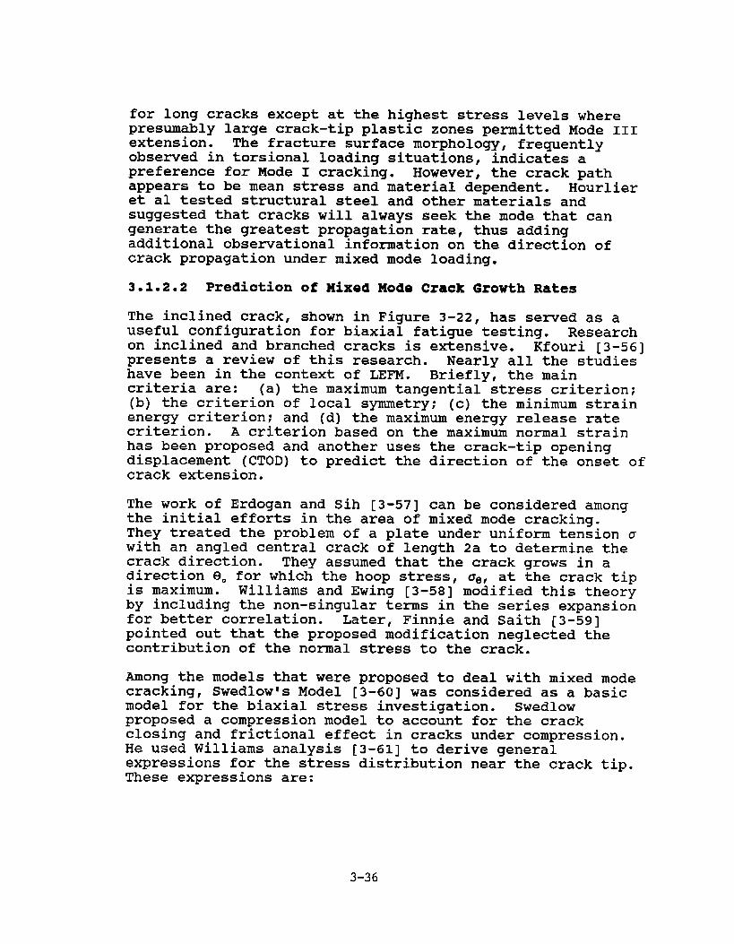
for long cracks except at the highest stress levels wherepresumably large crack-tip plastic zones permitted Mode IIIextension. The fracture surface morphology, frequentlyobsemed in torsional loading situations, indicates apreference for Mode I cracking. However, the crack pathappears to be mean stress and material dependent. Hourlieret al tested structural steel and other materials andsuggested that cracks will always seek the mode that cangenerate the greatest propagation rate, thus addingadditional obse~ational information on the direction ofcrack propagation under mixed mode loading.
3.1.2.2 Prediction of Mixed Mode Crack Growth Rates
The inclined crack, shown in Figure 3-22, has served as auseful configuration for biaxial fatigue testing. Researchon inclined and branched cracks is extensive. Kfouri [3-56]presents a review of this research. Nearly all the studieshave been in the context of LEFM. Briefly, the maincriteria are: (a) the maximum tangential stress criterion;(b) the criterion of local symmetry; (c) the minimum strainenergy criterion; and (d) the maximum energy release ratecriterion. A criterion based on the maximum normal strainhas been proposed and another uses the crack-tip openingdisplacement (CTOD) to predict the direction of the onset ofcrack extension.
The work of Erdogan and Sih [3-57] can be considered amongthe initial efforts in the area of mixed mode cracking.They treated the problem of a plate under uniform tension awith an angled central crack of length 2a to determine thecrack direction. They assumed that the crack grows in adirection BO for which the hoop stress, CT6,at the crack tipis maximum. Williams and Ewing [3-58] modified this theoryby including the non-singular terms in the series expansionfor better correlation. Later, Finnie and Saith [3-59]pointed out that the proposed modification neglected thecontribution of the normal stress to the crack.
Among the models that were proposed to deal with mixed modecracking, Swedlow’s Model [3-60] was considered as a basicmodel for the biaxial stress investigation. Swedlowproposed a compression model to account for the crackclosing and frictional effect in cracks under compression.He used Williams analysis [3-61] to derive generalexpressions for the stress distribution near the crack tip.These expressions are:
3-36
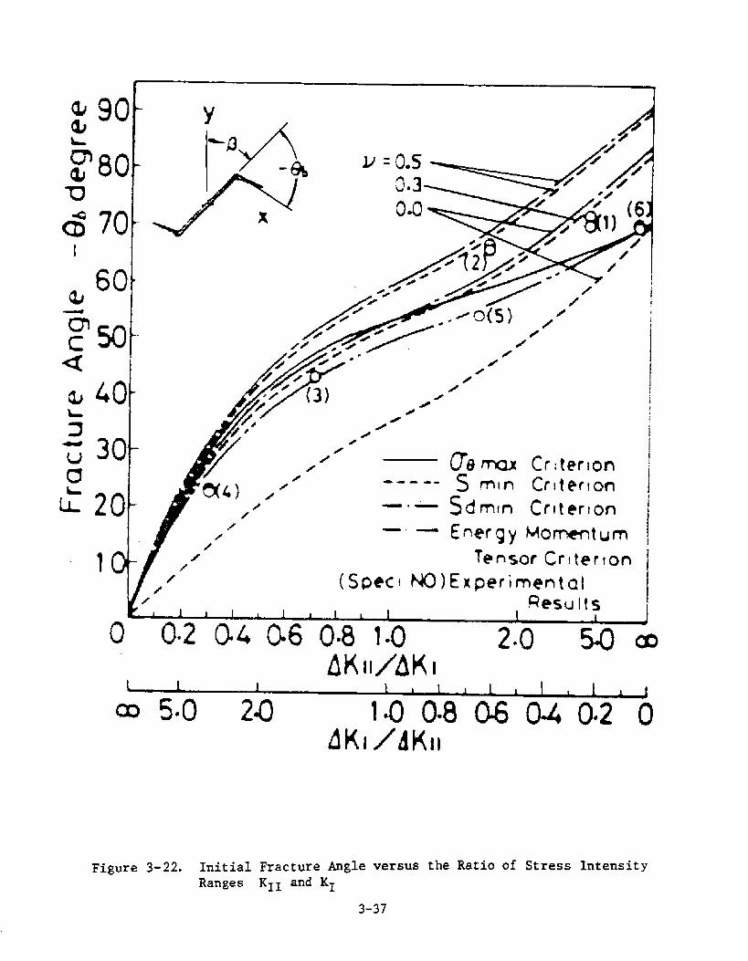
—
m 50
LO
30
20
10
0
1
-----
—.-
—.—
08 m Crlter
s m)n Crltefonml
Sdmn Criterion
Enwgy Mommtum
Tensor Criterton
Experirnenta~, Results/
1 1 1 1 1 1 I 1 L 1 1 1
0.2(M 06 0.8LO 2.0 5Q mf)KH/AKI
1 1 1 1 I 1 I 1 1 1 1 1 1 1co5*O 20 L0~8MQ40420
Figure 3-22. InitialFractureAngle versus the Ratio of Stress IntensityRanges K1l and K1
3-37
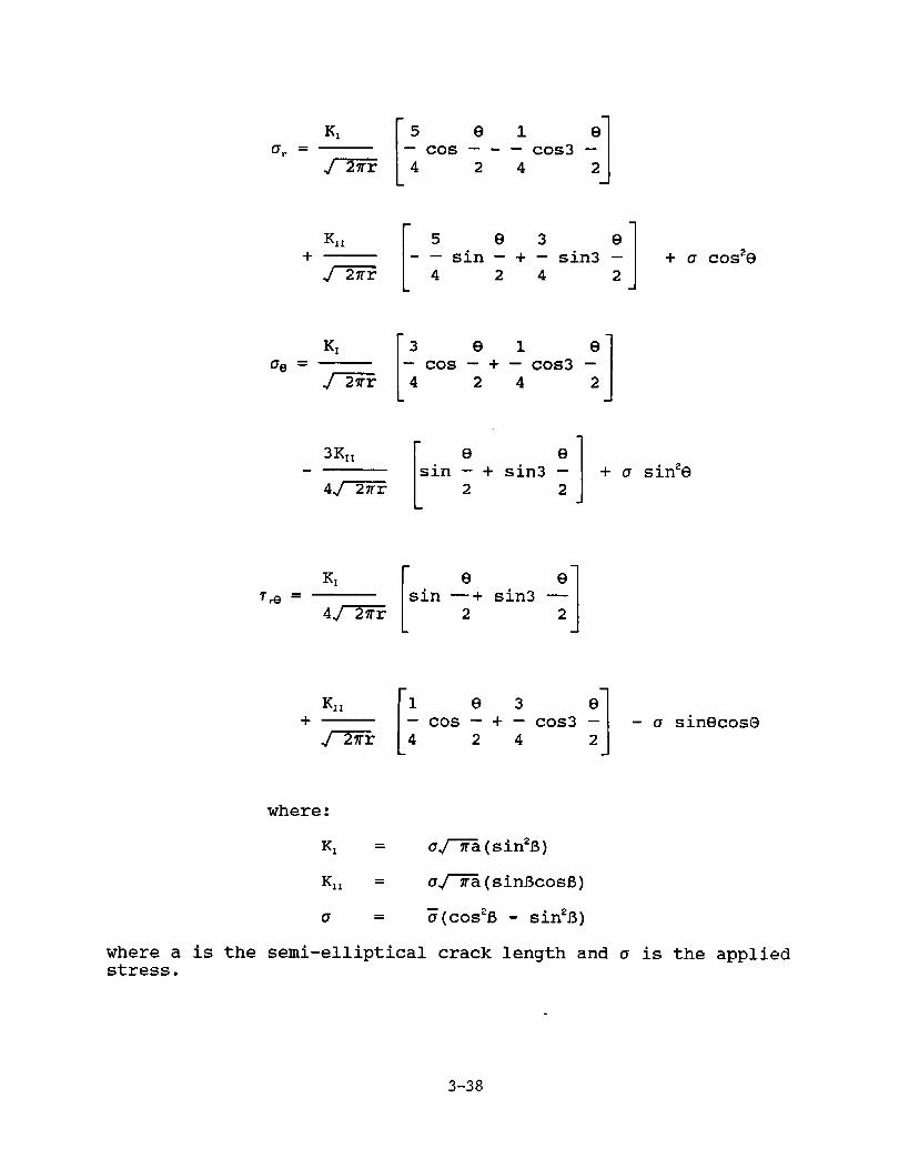
K,
[
5 el eUr = —cos —” —cos3—
=4242
5 e3 e-—sin —+ —sin3—4 24 2
L
KI
[
3 el eDe = –cos–+–cos3–
]=r 4 2 4 2 1L
K1
e esin – + sin3 –
2 2
r e eT* = sin —+ sin3 —
4~~r 2 21
+ a COS2(3
L J
KI~
[
1 e3 e+ –cos–+–cos3–
J=r 4 2 4 21-CTsin~cos@
where:
K, = u-a (sin2B)
K,, = a-a (sinBcosB)
o = G(cos2B - sin2fi)
where a is the semi-elliptical crack length and u is the appliedstress.
3-38

To take into account the crack closing and the frictionaleffect, Swedlow suggested that a should not be replaced by-a to express a compressive model. He postulated that whenK1 has negative values, it means that the crack is closingon itself and by such action, it causes friction on thesurface of the crack. Thus , in compression, KI can beneglected and the equations can be expressed as:
1
e 3 dor = I-–sin — + — sin3 —
m 4 2 4 21
+ u(sin20 - p~sin2B) sin2B + a~cosa
+ a(cOde - flfsin29)sin2J3+ u~sin2e
1 e 3 e– Cos — + — Cos —4 2 4 2
1
+ ~(cosesin e -u,cos2G) sin213+ fl,sin~coso
where a = -1, Uf is the coefficient
K1l= ~~a (sin
of friction, and
ficosB - #,sin’f3)
and
Ot = 3(cos213- sin2B)
These equations are applicable along the crack faces. Thecoefficient of friction may take a static or dynamic valuedepending on the motion of the crack faces. Using the
3-39

maximum hoop stress criterion of Erdogan and Sih and takinginto account the crack closing and the friction effect,Swedlow was able through his model to predict the initialfracture angle, BO, for an inclined crack under uniaxialcompression.
Another model related to this problem is one proposed by Wooand Ling [3-62]. They reviewed a number of fracturecriteria dealing with angled crack initiation ee and itsrelation to crack inclination angle B. They examined thebiaxial loading effect on the parameter used in eachcriterion for the prediction of the fracture behavior undermixed mode. In their experimental work, they used cruciformtype specimens of 1/8 in. thickness with an initial cracklength of 1-1/4 in. The material used in theirinvestigation was polymethyl-methacrylate (PMMA). Theiranalysis was an extension of Swedlow’s approach to the caseof biaxial tension-compression stressed models. This wasaccomplished by modifying Swedlow’s near-tip stressequations to the following forms:
K,
[
5 e 1 eor = — Cos — - — COS3 —
~)4242 1
K1l
[
5 e 3 e
+ - – sin – + — sin3 –
1
+ a,CO#e
-)4242
+ ansin2e + a~sin2e
K1
[
3 e 1 eDg =
1
– Cos – i“— COS3 –~)4242
3KII
[
e
1
e
sin – + sin3 – + u~sinze4J-@iq 2 2
+ ~nc0s2e - arsin2e
3-40

K,,
[
1 e3 e+ – Cos – + — COS3 –
I
- a~sinecos GJx) 4 2 4 2
+ ansin e cos e + 0fc0S2e
where
u“ = normal compression stress on the crack faces
D+ = frictional resistance due to the compressivestress (=fl~o.)
Mf = friction coefficient
at = u(l-a)cos213
They stated that the terms in the above equations will notappear at the same time and the selection of the properterms for a given problem was listed in a tabulated form asshown in Table 3-3. On the basis of their experimentalwork, they concluded that the maximum hoop stress criterionwas the most appropriate one to use for both the open andclosed crack conditions.
Zamrick [3-63] developed a biaxial stress model to predictcrack initiation angle, O., with respect to an inclinedcrack angle 13:
[ 1
l-3c0Se(a + tan’13)- (l-a) tanB
sine
3-41

CJf
a <0 uJ(rra)(sln2$+u co# ~) u~(m){l -a)sln # cosfl a(l-a) cos 2P
a<O: cr{(7Ta)(sln2#+a co# O u~(ma)(l -a) sln # GUSf3 9(1 -a) cos 2P
usln2/?>lalucos2@
acO~alucos2f32 usln2#: uj(fia)[(l-a)dn B cost
r91n#?cos#(l-a)> +pu(aCOS2J3+ sln2 #)] u(l–a) cos 2# a(aCOS21?+ 91n2P)
~dlalcos2B-sln2$)
131tto u{(~a) [(1 -a)sin $ cos#?
(In Swedlow’s form) +~u[acos2~ + sIn2 ~)] u(l-a) cos 2P a(acos2#+ sln2#) ~u(acos28+91n28)
Table 3-3. List of the Conditionsfor Choosingthe ProperTerms,Ling and Woo
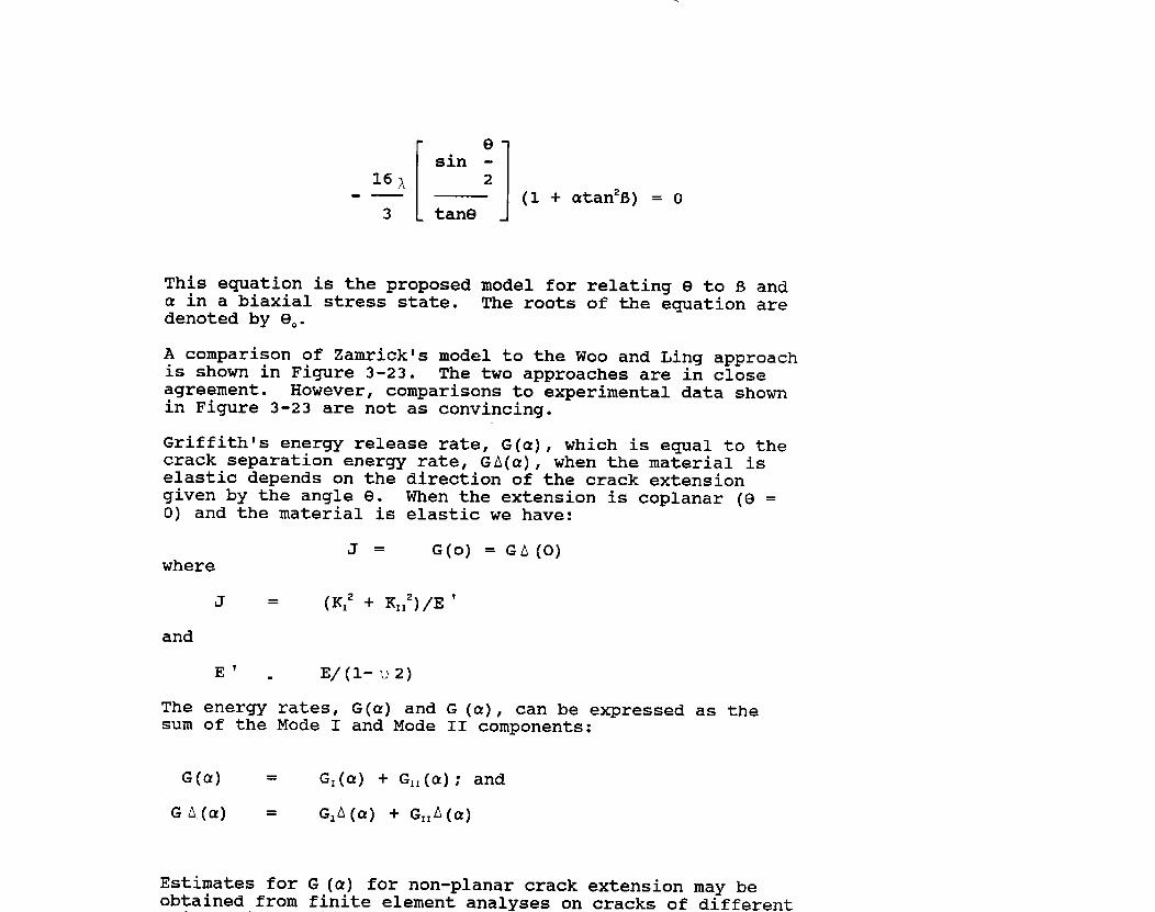
e
[1sin -16 ~ 2
.— (1 + atan213)= O3 tang
This equation is the proposed model for relating 9 to S anda in a biaxial stress state. The roots of the equation aredenoted by BO.
A comparison of Zamrickts model to the Woo and Ling approachis shown in Figure 3-23. The two approaches are in closeagreement. However, comparisons to experimental data shownin Figure 3-23 are not as convincing.
Griffith Is energy release rate, G(a), which is equal to thecrack separation energy rate, GA(a), when the material iselastic depends on the direction of the crack extensiongiven by the angle e. When the extension is coplanar (Q =O) and the material is elastic we have:
J = G(o) = GA(O)where
J = (K: + K,I’)/E’
and
E’ . E\(l-u2)
The energy rates, G(a) and G (a), can be expressed as thesum of the Mode I and Mode II components:
G(a) = GI(a) + GII(a); and
GA.(cc) = G,A(a) + G1lA(~)
Estimates for G (a) for non-planar crack extension may beobtained from finite element analyses on cracks of different

,
o-
.t-o-
“
-m
zG%HmlmIn
mo-
030-
Fracture Angle, f30(degrees)
oE
w4
wo 0
0 mo m
/
/
/
I1

125—
1
---- Ling and Woo—. Sih’s
PresentMethod
0 20 40 60 80 10C
CrackAngle, 6 (degrees)
Figure3-24. - Relationshipfor BiaxilityRatio,a = -1.0
120—
{
— — Ling and WooPresentMethod
A 1stMeasurement-100
0
I
2nd Measurement
i
E
a—
i
AA Q
i
i I “1 I Il’I’1 ’1’ 1’0 20 40 60 80 100
CrackAngle, ~ (degrees)
Figure3-25. - Relationshipfor BiaxialityRatio,a = -0.45
3-45

The agreement of any one approach is encouraging; however,no one approach is significantly highlighted by thesecorrelations. Also, few data points are presented forcorrelation. Therefore, further development of theseapproaches will be required before design applications canbe considered.
3.2 FATIGUE RESEARCH ON WELDED DETAILS
Few multiaxial fatigue approaches have been developed forwelded details due to the number of variables associatedwith the weld process and geometry. Nonetheless, a fewresearchers have attempted correlations for relativelysimple weld configurations and loadings and have had somesuccess. Review of this important research is presentednext.
3.2.1 Fatiae Life Estimates
Munse and Stallmeyer [3-65] investigated the fat@ue ofwelded plate girders with panel stiffeners shown in Figure3-26. Various stress formulations were tried to correlateS-N data. The most important finding is that most of thefractures occurred at stiffeners that were not in the regionof pure moment. In fact, most fractures occurred atstiffener’s ends where the flexural stresses wereconsiderably lower than the maximum flexural stresses.
An S-N curve is presented in which the maximum bendingstress on the extreme fiber at the location of failure isused as the ordinate. These data are shown in Figure 3-27.It is apparent from this plot that the maximum bendingstress at the fracture section does not provide a consistentrelationship in these tests either. A much bettercorrelation is obtained when the data are analyzed on thebasis of the maximum principal tensile stress (including theeffect of shear) at the point of failure. Data plotted onthe latter basis are presented in Figure 3-28. Althoughthere is still scatter in the test results, there is a well-defined scatter band for the entire range of fatigue lives.It appeared to the investigators that the shear and flexuralstress in the web of the welded members and the resultingprincipal tensile stresses, along with the stressconcentrations at the stiffener welds, produced the mostcritical fatigue conditions in the weldments withstiffeners. Maximum principal tensile stress predictedfatigue life including initiation and propagation.
Later, Moyar and Garg [3-66] re-analyzed some of the Munsedata using other fatigue criteria. They calculated thestresses in the vicinity of fatigue cracking and correlatedthe data based on maximum principal stress, modified range
3-46

Fig ● 3-26 –Details of various types of stiflener
Fig. 3-27
—SiN diagram jor amaximum berrdi~ z
,o~ r ‘J ! :-”-’’rnAo’‘“’”’4’+’0’’’’”Stiffener type lA~BiCIDIEIF!F,lFz
stress at failure s~crion Q 10+— I..—.——.__. ) I
Zero-to-tension stress cycles \ I I1 I 1
lx 10s 2X10⁵ 5xlo~ IxlobCYCLESTO FAILURE
2xlob 6x10b
Fig. 3-28
—S N diagram forma,rimurn principa[tensile srrex.~ arfaiiure section
CYCLESTO FAILURE
3-47

of shear stress, and maximum octahedral shear stressapproaches. The results of these tests are summarized inTable 3-4. Both the modified range of shear stress andmaximum octahedral shear stress criterion provided bettercorrelation with obsemed data for stiffened welded platebeams. However, this analysis is based on a few tests andcorrelations are not very convincing in the low cycleregion.
Lawrence [3-67] recently proposed an approach for predictingcrack initiation and growth in simple weldments undercombined loading (tensile and flexural moment) . Thisapproach is based on the ability to determine a stressfatigue notch factor for axial and bending load conditionsin the vicinity of the weld toe and predicting the state ofstress at the notch by superimposing tensile stress. Thisapproach also includes the effects of mean stress andresidual stress.
Lawrence proposed that for long fatigue lives and constantamplitude loading conditions, the notch root stresses aremostly elastic and the residual stresses can be considerednot to relax. Under these conditions, the Basquin equationcan be used to estimate fatigue life:
S.K, = (a’,- K,S. - a,)(2N,)b
where a ~ is the fatigue strength coefficient (a’~= Su + so(ksi units)), S. is the remotely applied mean stress, a. isthe notch-root residual stress and K, is the appropriatefatigue notch factor. Expanding the mean stress (S.) toinclude both (applied or induced) axial and bending meanstresses (S~Aand S.B), and considering both applied andinduced cyclic axial and bending stresses through thefollowing equation:
eff BK = (l-x)KA + XKfmax fmax fmax
B Tx =s/s
a a
A Bwhere K and K are the worst-case-notch fatigue notch
fmax fmaxfactor for axial and bending load conditions, respectively;
3-48

Table 3-4
Re-Analysisof Plate GirderData by Moyer
.
SPEC, OBS . MAX.PRIN. MAX.SHEAR MAX.OCT.# CYCLES STRESS THEORY STRESS THEORY STRESS THEORY
----------- ----------------------- ----------AA- Ffi!L PREDICT I)lFF. PREI)lCT DIFF. PREDICT DIFF.+Sc
0----------------------------*.---,------*.---..--_-__---,.----=,
29(0)B 0.6278 0.1426 -0.4852 0.3868 -0.2410 0.3456 -0.2822
30(0)B 0:4467 0.0731 -0.3736 0.2836 -0.1631 0.2355 -0.2112
31(0)B 0.5236 0.0744 -0.4492 0.2884 -0.2352 0.2399 -0.2837
41(0)B 1.1103 0.4438 -0.6665. 1.0261 -0.0842 0.9188 -0.1915
43(0)B 1.2719 0.8111 -0.4608 1.2522 -0.0197 1.1994 -0.0725
MEAN -0.4871 -0.1486 -0.2082
STD.DEV . 0.1086 0.0962 0.0864
COMPARISON OF PREDICTED CYCLES TO FA~URR (TN MTT,T,Tfi~s)OF TYPE B=AMS USING PROPERTIES FROM TYPE C BEAM BATA
AND BIAXIAL FATIGUE THEORIES
3-49
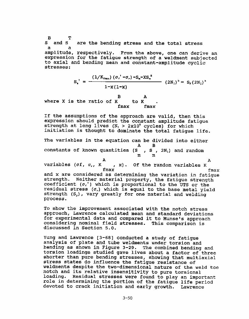
B TS and S are the bending stress and the total stressa a
amplitude, respectively. From the above, one can derive anexpression for the fatigue strength of a weldment subjectedto axial and bending mean and constant-amplitude cyclicstresses:
(I/K,..,)(u,‘-a,)-Sm-XSmBSa’ = (2NI)b= S,(2NI)’
1-X(1-X)
B Awhere X is the ratio of K toK .
fmax fmax
If the assumptions of the approach are valid, then thisexpression should predict the constant amplitude fatiguestrength at long lives (NT > 2X10E cycles) for whichinitiation is thought to dominate the total fatigue life.
The variables in the equation can be divided into eitherA B
constants of known quantities (S , S , 2NI) and randomm m
A Avariables (of, ar, K x) ● Of the random variables K
fmax’ fmaxand x are considered as determining the variation in fatiguestrength. Neither material property, the fatigue strengthcoefficient (a~’) which is proportional to the UTS or theresidual stress (u.) which is equal to the base metal yieldstrength (SY), vary greatly for one material and weldingprocess.
To show the improvement associated with the notch stressapproach, Lawrence calculated mean and standard deviationsfor experimental data and compared it to Munsels approachconsidering nominal field stresses. This comparison isdiscussed in Section 5.0.
Yung and Lawrence [3-68] conducted a study of fatigueanalysis of plate and tube weldments under torsion andbending as shown in F@ure 3-29. The combined bending andtorsion loadings studied gave lives about a factor of threeshorter than pure bending stresses, showing that multiaxialstress states do influence the fatigue resistance ofweldments despite the two-dimensional nature of the weld toenotch and its relative insensitivity to pure torsionalloading. Residual stresses were found to play an importantrole in determining the portion of the fatigue life perioddevoted to crack initiation and early growth. Lawrence
3-50

IIIIIIII
II
IIIII1
Q(9m
m
:
saJJ-1m
wo
t
3-51

found that the rnultiaxial fatigue theories of Lohr andEllison and Kandil, Brown and Miller gave best estimates offatigue crack initiation life, as shown in Table 3-5, whenthe notch root strains could be determined by finite elementanalysis as shown in Figure 3-30. Estimates of initiationlife based on Basquin’s equation modified for multiaxialstresses (principal stress and an equivalent stress) gavepredictions for long-life high-cycle fat@ue which werewithin a factor of three of the obsemed total lives, asshown in Table 3-5.
Siljander et al [3-69] recently investigated the propor-tional and non-proportional multiaxial fatigue of tube-to-plate weldments. This work was conducted to support thedevelopment of a multiaxial fatigue design procedure forbuilt-up plate bridge girders. Bridges experience non-proportional out-of-phase stresses as vehicles move acrossthe bridge. One of the most interesting aspects of thestudy is the analysis of the principal stresses in girderswith moving loads to determine representative out-of-phaseloadings. They correlated their data using various damagecriteria. As in many structural codes, principal stressrange used von Vises effective shear stress range and acritical shear plane approach originally developed byFindley. Of these approaches the critical shear planeapproach correlated the proportional and non-proportionaldata quite well as seen in Figures 3-31 through 3-33.Several of their findings in achieving this degree ofcorrelation are noteworthy. First, the test specimens werestress relieved to eliminate residual weld stresses. Thisproduced a significant reduction in data scatter. Second,the investigators used stress concentration factors at theweld toe that are developed in part by a complex 3-D finiteelement analysis with the added advantage of havingknowledge of weld profiles, information that is notavailable with certainty to structural designers.
3.2.2 Fatiqu e Pro~aqation in Welded Structures
Multiaxial fatigue procedure for crack propagation have beenexamined because weld flaws are often present at crackinitiation sites as discussed by Thayamballi [3-70] and manyothers.
Procedures have been identified for estimating the stressintensity factor for Mode I, KI,propagation in complexstress fields. The first approach identified is theinfluence function technique presented by Bueckner [3-71]:
Ja
K= h(x)u(x)’dxo
3-52

Table 3-5
Researchon Butt Welds & CruciformFilletWelds by Lawrence
.
StatisticalS~g of the Deparmres ofPredictedLives from Fatlgut Test Data
Mmse’s Miner’s Gurney’s MS Method I-P Model.
No. ofCases 29 29 29 13 29
Fp 1.061 1• 015 0.894 0.906 1.016
‘Fp0.124 0.093 0.081 0.052 0.067
l%o (Nprediction)Fp : lleanvalue of F~; Fp -
10$10 (NTe~~), ● unity of Fp value
representsthe perfect●greement betweenthe prediction●nd fatiguedata.
CaFp
: Coefficientof Variationof Fp.
3-53

4Figure 3-3o. Finite Element Mesh of Tube-to–Plate Welds
(Ratio of Notch-Root Element Size to NotchRadius = 1:4)
3-54

10J
102
1 1
0
AAO
++++ .4 A-
●
105
D *
0 Bendingonly(A=-)● Torsiononly(~=O)A In-phasecombinedMding-torsion(~=7.34)A Ln-phasecombinedbmding-[orsion ( ~ = 2.39)
❑ In-phasecombinedbending-~orsion(A= 1)
+ Out-of-phasecombinedbending-torsion(A=2.39)
106~clestofailure10’
108
Figure 3-31. The Maximum“WorstCase”LocalPrincipalStressRangeversusCyclesto Failure
3-55

10’
102105
0 Bendingonly(~=M)● Torsiononly(~=O)A In-phasecombinedIwuling-torsion(~=7.34)A In-phasecombinedknding-torsion(A=2.39)
•l In-phasecombinedixnding-torsion(A= 1)+ Outaf-phasecombinedMiding-torsion(~=2.39)
106 107Cyclestofailure
10s
Figure 3-32. The “Worst Case” Local von Mises’ EffectiveStress Range versus Cycles to Failure
3-56
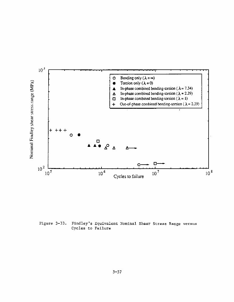
1050 Bendingonly(A==)● Torsiononly(~=O)A In-phasecombinedbending-torsion(A= 7.34)A In-phasecombimxlknding-r.mien(A=2.39)Q In-phasecombinedIxnding-[orsion(A= 1)+ Out-of-phasecombinedknding-mrsion(A=2.39)
k+++00
❑
102105 106
Cyclestofailure107 108
Figure 3-33. Findley ’s Equivalent Nominal Shear Stress Range versus
Cycles to Failure
3-57

where
h(x) = intensity arising from a unitlocation x on the crack face
load at
u(x) = untracked stress
This approach has the advantageto develop. It’s disadvantagesthe load is symmetric about the
distribution
of being relatively simpleinclude the assumption thatcrack face.
The second approach for estimating stress intensities incomplex stress patterns from geometric configurations isgiven by
where
K
M,
M,
Mb
@
Gurney [3-72]:M~M,M~
K= a J=#
= ~ ~ is baseline stress intensity for thethrough thickness crack
= stress concentration factor at welded toe
= front face correction for secondary bendingat crack tip
= back face correction for finite thicknessplate
= geometric factor for semi-elliptical surfaceflaw
The advantages of this approach are, again, its relativeease of application. However, factors must be developedspecific crack geometries and stress conditions.
for
The third approach for estimating stress intensity factorsis by finite element techniques with a crack element in themodel. This approach is illustrated in Figure 3-34. Theadvantage of this approach is that it accounts for complexstress patterns and crack geometries and elastic and plasticconditions around the crack tip. Disadvantages of thistechnique are that it is relatively time consuming andexpensive at this time. This situation is expected tochange in the future as more computational techniques aremade available and computer capabilities increase.
Of the three approaches, the later has been proposed mostrecently for applications. Most importantly, crack growthunder multiaxial loading has been shown to occur along a
3-58

Finite Element I’lodelof StructureAdjacentto the Crack Tip
Crack Tip Element
Figure 3-34. Illustration of Estimating Stress Intensity byFinite Element Analysis
3-59

path that maximizes Mode One component K, (Hellen [3-73])and strain release rate G (McDonald [3-74], Haung [3-75]).This is a controversial finding with conflictingexperimental results. However, if validated for use inmarine structures, it would facilitate development of anapproach for predicting multiaxial fatigue response inwelded structures. This factor alone makes prediction offatigue crack growth in welded structures worth furtherconsideration.
There is evidence that multiaxial stress affects the fatiguelife of welded joints as indicated by Sih [3-76]. The cracktrajectory emanating from a flaw at an angle to theprincipal stress is neither exclusively a function ofprincipal stress nor the stress component perpendicular tothe flaw. This is also true for welded tubular joints bythe experimental observations of McDonald et al [3-74].Furthermore, there is evidence [3-76] to indicate thatcracks grow along a tuned path through thickness underchord-brace intersections. The direction of a growingfatigue crack in a complex stress field has been the subjectof several hypotheses. It is argued by Hellen [3-73] thatthe crack develops in such a way as to maximize the Mode Icomponent KI, or that the path maximizes the strain energyrelease rate G [3-77, 3-78]. Insight into the direction ofcrack growth can be obtained by considering the effect of asmall angle kink on the crack tip. The local Mode I andMode II stress intensity factors on the kink are denoted KIand KIIcan be expressed in terms of the Mode I and Mode IIcomponents KI and KIIon the main crack following the work ofBilby [3-79]; Hussain et al [3-80]; and Masahiro et al [3-81]. Although the analyses differ on detail they givebroadly similar results. The angle of the crack for atubular joint weld is shown in Figure 3-35. The angle ofthe kink which maximizes KI and makes KIIzero is close to 15degrees for crack length to thickness ratio a/T=.2, 20degrees for a/T=.6, and approximately 55 degrees for a/T=.9.The local strain energy release rate G for the kink can bedetermined by combining the local KI and KII,or be obtainedby aft axis virtual crack extension. For the case shown inFigure 3-35 crack paths which maximize KI and G are similar.These are plotted as three piece wise linear segments andcompared with the path observed experimentally by Rice aspresented by Haung et al [3-82].
F!hee [3-76] has presented two techniques for computingstress intensity factors for welded structural details. Thefirst method is based on development of an effective stressintensity factor (K.) for mixed mode crack propagation andthe second is by using a special finite element program forestimating stress intensity factors.
3-60

H
H
m4-I
cd
um‘3
.
5
(smma) mm
3-61

The equivalent stress intensity factor, K., is convertedfrom the appropriate energy release rate, G:
K=* l-u2 K 2III—=G=— K12+ K112+E E 1-L!
This equivalent stress intensity factor represents the crackdriving force which incorporates all the KI, KIIand KIIIcomponents of a mixed mode problem. For a mixed modeproblem, any single component of the stress intensityfactors cannot represent the crack driving force properlysince crack propagation is a combined result of thecontributions of all three stress intensity factors of theproblem. A comparison between K. and any individualcomponent of KI, KIIand K1ll can indicate the contribution ofsuch an individual component to crack propagation. For thebrace tension cases, it is apparent from Figures 3-36through 3-39 that, throughout the crack front, the fatiguecrack propagation will dominate the Mode I stress intensityfactor KI. However, for the in-plane bending cases, the K,contribution to K. is negligible except for a small lengthnear the surface. Therefore, if the considered flawgeometry is practical for a fatigue load system whichconsists of a significant contribution of in-plane bending,a fatigue crack growth analysis should consider all three --K~, KIIand K,,,.
A crack driving force parameter such as K, has yet to beestablished as a parameter through which the fatigue crackgrowth behavior of a mixed mode flaw can be directlycalculated in a manner similar to the KI of a Mode Iproblem. Expressions similar to the present K. have beenstudied for limited mixed mode problems [3-83, 3-84] such asproblems with K, and KHowever,
IImixed and with KI and KIIImixed.few fully mixed mode problems, such as those
present, have been studied.
Rhee has also presented a method to calculate the stressintensity of an elliptical flaw using a specialized finiteelement computer approach. This method, called the FiniteElement Alternating method, can solve the problem of anelliptical flaw under arbitrary normal and shear stresseswhich can be expressed in higher-order polynomials [3-85through 3-87]. The Finite Element Alternating methoditerates through the following steps.
1. Using the solution of an elliptical crack in aninfinite solid and subjected to a constantpressure, the surface traction aYY, rYXand ~Y,arecomputed on y=-h plane.
3-62

IP9: o-36. mm; c-136,mm
tao-wx -
1
m t
TORSION:o-36.mm; c9136.mm
Tgo- wx -1 -
I ●
K1
Figure3-36. StressIntensityFactorsof WeldToe SurfaceFlaw(In-PlaneBending)
Figure 3-37. Stress intensityFactors of WeldToe Surface Flaw(Torsion)
3-63

Temskon:o-36.mm;c_136.mm
‘eff
\wG-
E
OPB: 0-36. mm; c-136.mm
IKll
11
Figure3-38. StressIntensityFactorsof WeldToe SurfaceFlaw(AxialTension)
Figure 3-39. Stress IntensityFactors of WeldToe Surface Flaw(Out-of-PlaneBending)
3-64

2.
3.
4.
The residual tractions acting on y=-h plane arethen freed by applying opposing surface tractionson the plane of an untracked, semi-infinite solid.The resulting residual normal stress, a==,on thecrack surface location is calculated.
The residual normal stress, u==,on the cracksurface is removed by an opposing stress. Thisopposing stress results in the stress intensityfactors along the crack front and the surfacetractions on y=-h plane, which can be calculatedusing Segedinis potential function [3-88].
Steps 2 and 3 are repeated until the resultingresidual stresses on the crack tip surface becomenegligible when compared to the applied stress ofr. The result of all the iterations aresuperimposed to obtain the stress intensityfactors for the elliptical crack of the originalproblem.
This approach has been successfully applied to obtainaccurate stress intensity factors in finite thickness plate[3-87], in pressure vessels [3-89] and for quarter-elliptical corner crack emanating from a pinhole in platesand in aircraft attachment lugs [3-90].
In the finite element alternating method, the solutions ofan elliptical flaw in an infinite body are obtained throughthe Trefftz’s potential function method [3-91]. In thisprocedure, extensive numerical calculations are involved toevaluate the various forms of elliptical integrals requiredfor the solutions. The finite element solution method isused to obtain the solutions of the untracked body underarbitrary boundary tractions. The boundary tractions, whichresult from the above elliptical flaw problem, are firstconverted into the boundary nodal forces of the finiteelement model without a crack and then applied as theexternal loads to calculate the stresses on the cracklocation. These solutions are used following the sequencesdiscussed earlier to obtain the stress intensity factors.
Another finite element based approach for calculating crackpropagation in welded details was presented by Haung [3-92].His approach is based on the work of Rice and Levy [3-93]where the crack is represented by a series of generalizedline springs which act across a discontinuity in a thinshell. The approach was originally developed for Mode Iloading but has been further generalized by Parks [3-94] andDesvaux [3-95] to incorporate both Mode II and Mode IIIloadings and is implemented in the finite element codeABAQUS [3-96].
3-65

Haung [3-92] presented results comparing the line springmodel to three-dimensional finite element analysis and toexperimental crack growth rates for a chord and braceintersection.
A fracture mechanics fatigue analysis method explicitlyconsiders the flaw geometry, which is one of many criticalcharacteristic of the problem. The necessity to considerthe flaw geometry in a fatigue analysis, in turn, can make arigorous crack growth analysis prohibitively expensive. Theeffort required for the evaluation of the stress intensityfactors can be significant, even for a simple flaw geometry.Especially for a surface flaw, which is a common form ofweld toe defects in a marine structure and whose stressintensity factors can only be practically evaluated througha numerical method such as the finite element method, theinvestment required for the evaluation of the stressintensity factor solution is enormous.
To perform a rigorous fatigue crack growth analysis of asurface flaw, which changes its size and shape continuouslyunder fatigue loading, the stress intensity factors of agroup of flaws with different dimensions are required tocover a certain range of flaw shapes and sizes. For thestress intensity factor calculation using the finite elementmethod, which is the most popular at present, the majorityof the analysis effort is devoted to modeling the finiteelement meshes.
3-66

4*O APPLICATION OF MULTIAXIAL FATIGUE RESEARCH TO KARINESTRUCTURES
Marine structures are subjected to various loads and localeffects that are combined in structural details. Theseloadings contribute to fatigue in the details. In thissection, the stress characteristics described in Section 2.1.1and multiaxial fatigue approaches presented in Section 3.o arecompared to identify candidate multiaxial fatigue approachesfor marine structures and to help identify areas whereadditional research is required. Table 4-1 has been preparedto summarize the proposed approaches identified during thecourse of this project and to highlight, for quick reference,areas in which gaps in technology exist. Further discussionof the applicability of multiaxial fatigue research to marinestructures follows.
4*1 SHIP STRUCTURE APPLICATIONS
Returning to our examples of representative structural detailsin ship structures, we will present relevant methods that havebeen proposed for predicting multiaxial fatigue response.
The first detail considered is the cutout in a transverse webframe. The cutout is to allow longitudinal panel stiffenersto pass through continuously in order to carry longitudinalprimary hull bending stresses. There have been studiesconducted on this detail [4-1] to determine the state ofstress. AS discussed in Section 2.0, there are biaxialnominal stresses adjacent to the cutout caused by distributedlateral load on the girder resulting in flexural bending andshear stresses. However, at the edge of the cutout, wherecracks are known to propagate, the stress is axial tension orcompression. The principal stress field has mean stresscomponents from hydrostatic loads and varying principalstresses from variations in hydrostatic loads as waves areencountered. Therefore, on a detailed level, the stresses arenot at all multiaxial, but on a nominal stress level, thestresses are biaxial as indicated by Munse and others. Munsesuggested shear stress as the correlating nominal stress forthis flexural member with cutouts.
The second example detail is a hatch corner cutout. The hatchcorner is a source of stress concentration. The state ofstress in the vicinity of this cutout is biaxial resultingfrom combined axial torsional hull loading. However, as withthe previous cutout, the stress state on the face of thecutout is axial. Research by Chen [4-2] and Munse [4-3]
4-1

TABLE 4-1
=RY OF HETH~S F~ ESTIMATING FATIGUE RESPCMSETO C(MPLEK LOAOING
LOADI kkG’ RELIA
(IMITIAPPR
O
RESPONSE HULT[AXJAL APPROACHES’
STRUCTURALDETAIL
LOCALGLOBAL DETAIL’ STRESS/STRAIN3 INITIATION PROPAGAT10kk BIAS
*
longitudina~Cutout in Web
Lateral loadingfrom hydrostaticuave variations.Cargo loadinginternally(tankers)
F(exural bendingand shear fromiaterat load
Axial atresa atedge of cutout,biaxial opposingprincipalstresses adjacentto cutout
Maximm shaaratress (Hunse)
h!aximun stress*(Fricke)
Hatch Corner
~
M
Longitudinal uavebending,torsional hullflexing
AxialIondingfrom hull bendingati shear frmnf~exing
Axiai stress atedge of cutout,opposingprincipalatressea adjacentto cutout
Maxim stress* @lode I, max(Chen) princips~ in
plane stress(Chen, Uirsching)
CVK longitudinal naveherding, lateralhydrostatic loadvariations fromwaves
Axia( respnaefrun Iongitudina[bending, flexuralbending and shearfr~ tatera( load
Biaxia[ opposingprincipai atress
Principa[ stress* Hode I msxinnn -(Hunae) for principet atreaafatigua life
t4axirmm shear*stress (Moyer,Garg) for crackinitiation
Critical shearplane whereprincipalstresses are outof phase(Laurence)

TABLE 4-1 (cwititwed)
~RY OF HETMX)S F~ ESTIMATING FATIGUE RESPCMSETO ~PLEX LWIBG
LOADING’ RESPONSE 14ULT1AK[ALAPPROACIIES” REL
INITIATION
(INITAPP
O
STRUCTURALOETAI L GLOBAL
LOCALSTRESS/STRAIN’DETAIL2 PROPAGATION BIAS
1.016Butt HeLded Plate Longitudinal hu(luave bending,lateralhydrostatic loadvariations fromnaves
Longitudinalprimary beiwlingstress, h-dingand tiranestress fromLateral load
Biaxial opposingprinci~lstresses,residual stresspresent
Principal stress(Laurence)
Principat atressfor fatigue life*(Stambaugh)
!faxi- principalstress (Lawrence)
Offshore Structures
T-ls, K-K, K-T Uave loading andout of plane drag
~ and inertia(w forces from
orbitalvelocities
Axia( stress andWnching shear,loading stressfran out of plane1Oads
Triaxia~ opposingprincipalstresses andshear
Haxitiprincips~ atressor shear stressmaxinwm (BUI,Gurney)
Strain energyrelaase rate formixed mode 1, II,[1[ (Haung, Rhee)(proposed for T-joints butapplicable tomore carp[exjoints)
Bending frmncurrant forces
Connect ors High pre-tensionand varying axialstresses intension legs,axial andtorsional loadsin risers
Biaxia( andtriaxiel opposingprincipal stressand strain
Equivalent*stress, Guest lawand critica[plana approachesfor out of phaserndtiaxialstresses

TABLE 4-? (continued)
~Y OF HETHOOS FCHI ESTIMATING FATIGIE RESPLMSE TO ~LEX LOADING
NOTES:
1. Hypothetical Ioadinga are presented.
2. GLobal detai[ reaponae refers to nominal state of stress external to notches and Local geometry.
3. Actual statea of stress vary depending on magnitudes of live and dead loads (e. g., deperding on state ofencountered uavea). This situation can actua[ly change the location of maxinwrn stresses in the detai[.on stress/strain characteristics.
4. klultiaxial approaches refers to s method for characterizing fatigue response under comp(ex
5. COV are for combined axia( ❑ti bending on the butt uetd, no biaxial stresses.
6. Joints are ccmbind out of plane intersections.
* Approach reccmmeruied by the investigators.
nwan stress or even direction ofSee text for additiona[ discussion
oading conditions.
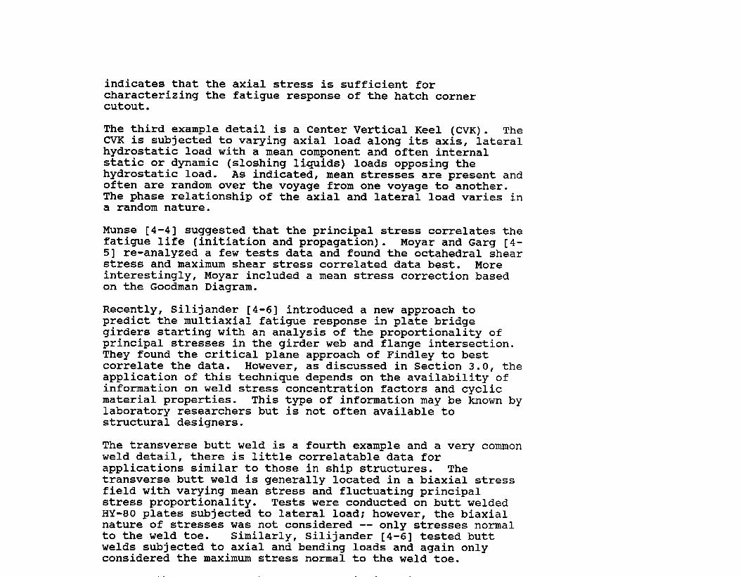
indicates that the axial stress is sufficient forcharacterizing the fatigue response of the hatch cornercutout .
The third example detail is a Center Vertical Keel (CVK). TheCVK is subjected to varying axial load along its axis, lateralhydrostatic load with a mean component and often internalstatic or dynamic (sloshing liquids) loads opposing thehydrostatic load. As indicated, mean stresses are present andoften are random over the voyage from one voyage to another.The phase relationship of the axial and lateral load varies ina random nature.
Munse [4-4] suggested that the principal stress correlates thefatigue life (initiation and propagation). Moyar and Garg [4-5] re-analyzed a few tests data and found the octahedral shearstress and maximum shear stress correlated data best. Moreinterestingly, Moyar included a mean stress correction basedon the Goodman Diagram.
Recently, Silijander [4-6] introduced a new approach topredict the multiaxial fatigue response in plate bridgegirders starting with an analysis of the proportionality ofprincipal stresses in the girder web and flange intersection.They found the critical plane approach of Findley to bestcorrelate the data. However, as discussed in Section 3.0, theapplication of this technique depends on the availability ofinformation on weld stress concentration factors and cyclicmaterial properties. This type of information may be known bylaboratory researchers but is not often available tostructural designers.
The transverse butt weld is a fourth example and a very commonweld detail, there is little correlatable data forapplications similar to those in ship structures. Thetransverse butt weld is generally located in a biaxial stressfield with varying mean stress and fluctuating principalstress proportionality. Tests were conducted on butt weldedHY-80 plates subjected to lateral load; however, the biaxialnature of stresses was not considered -- only stresses normalto the weld toe. Similarly, Silijander [4-6] tested buttwelds subjected to axial and bending loads and again onlyconsidered the maximum stress normal to the weld toe.

are presented in Appendix B. Equivalent shear stresstechniques modified for mean stress effects provided very goodpredictions of fatigue life of a laterally loaded plate with abutt weld based on uniaxial data. It was found, however, thatmultiaxial approaches based on cyclic strain fatigueproperties were not easy to apply because at this time theseproperties are generally not known for ships and offshorestructures. Additionally, stress concentration factors forweld geometry have a large influence on fatigue responsedepending on the weld profile and quality. The HY-80 platebutt had a quality weld and low weld profile resulting in astress concentration factor of about 1.15, not a typicalstress concentration for welds.
The foregoing discussion illustrates the variability of loadcharacteristics and geometry of ship structures and thedifferent multiaxial fatigue approaches that are applicable toeach type of detail.
Additionally, only a few data points were generalized tosupport the research and are insufficient for use indeveloping confidence in statistical parameters (bias andscatter) needed for reliability analysis.
4.2 OFFSHORE STRUCTURE APPLICATIONS
Currently there are two distinct approaches for predictingfatigue response in offshore structures. The first is afatigue life approach based on S-N curves [4-7] developed forvarious joint configurations. This approach is the mostwidely used in the industry and uses the maximum stress normalto the weld toe and neglects interaction effects for out-of-plane joint configurations. The British DOE rules [4-8]address complex stress distributions by correlating fatiguedata using maximum principal stresses at detail “hotspots” asdiscussed in Section 2.2.1 of this report. Yung and Lawrence[4-9] have used maximum shear stress and octahedral shearstress to correlate tube and plate high cycle fatigue responseunder multiaxial loading.
The second approach for fatigue response prediction that isgaining wider acceptance is the fracture mechanics approach.Multiaxial stress distributions are being considered.However, validation efforts are very limited in number, detail

Rhee presented estimates of stress intensity factors formultiaxial loading based on finite element analyses and usingan equivalent stress intensity factor as discussed in Section3.2.2. Figures shown in Section 3.2.2 present the resultingstress intensity factor solutions of two flaw geometries.These plots show that the in-plane bending load cases arepredominately mixed mode. All the solutions along the crackfront location where the negative Mode I stress intensityfactor is developed (for the in-plane bending cases) are notaccurate since a negative KI indicates the crack surfacecontact and penetration which developed in the analysis werephysically impossible. These negative values could beeliminated with a proper multicomponent contact algorithm. Acomparison between & and any individual component of KI, KIIand KIIIcan indicate the contribution of such an individualcomponent to crack propagation.
While Rhee’s K. is attractively simple, the approach isobviously limited to linear elastic fracture mechanicsassumptions in the high cycle range of crack growth. Itobviously does not account for crack tip plasticity observedin mixed mode tests as discussed earlier.
Huang [4-10] presented a more simplified approach forcalculating mixed mode crack growth in welded tube jointsusing finite element analysis, line spring elements, and theenergy release rate G. Haung compared his approach toexperimental results and found good agreement for cases whereMode I dominates and cracks are not long, 0.8 2 (a/T) 2 0.2.This technique is again limited to basic limitations of linearelastic fracture mechanics and does not account for mean andresidual stresses, random effects or interactions withcorrosive environments. Additionally, there are conflictingreports on the accuracy of assuming Mode I dominant crackgrowth.
Another type of offshore structure in which multiaxial fatigueconsiderations are important is riser connectors. Theseconnector systems, illustrated in Figure 4-1, are oftensubject to high pressure loads and tension and torsion loadsthat fluctuate about a mean stress. There are severalmultiaxial fatigue approaches that are good candidates forthis type of loading, especially those in which tension andtorsion type loads dominate. The automotive and heavyequipment industries have been very active in research ontension and torsion multiaxial fatigue with severalspecialized approaches investigated by Tipton and Nelson [4-11] which have been described previously. However, these
4-7

l’ilbumrPI- %ctlofl Pin %dlon\
——. . -. --— ..
16.W 2(W
3“ ~ 17.5-.~25.8*..–.. _
w“-%?30” ~ ,
\\?.’..\:?>::,.”... . . .. . ....’.: ‘. ..-—i I
s- L13.&-lI i
26.0”OD 16.~ ID 20.ti OD
(b) Threadd Ccmnectw
Figure 4-1. Tension Member and Connector with High Pre-Load
4-8

approaches should be subject to verification using offshorematerials and the exact geometries used in connectors.
The equivalent stress techni~es have been used most oftenbecause they are easiest to apply and required material datais available. Of the equivalent stress techniques reviewed,maximum shear stress techniques generally predict crackinitiation and equivalent principal stress is most useful forpredicting fatigue life where crack propagation lifedominates.
However, from the foregoing discussion and the summary inTable 4-1, there is no universal technique for predictingmultiaxial fatigue response for each varied application inmarine structures. This is because marine structural detailsvary in geometry, applied load, stress state and fabricationprocedures. Unlike pressure vessels or rotating machinery(where these approaches have been applied) there are a greatnumber of variables for each structural detail.
4.3 FACTORS INFLUENCING MULTIAXIAL FATIGUE RESPONSE IN MARINEDETAILS
The many factors which influence fatigue response in marinestructures were discussed in Section 2.1. The factors thathave influence in fatigue response of welded details arediscussed here along with the research conducted to determinetheir influence on multiaxial fatigue response and prediction.These factors include stress gradients, stress proportionalityand phasing, elastic and plastic strain relationships, meanand residual stress, random loading, corrosion, thicknesseffects, materials and fabrication procedures. A data set hasbeen identified where several of these effects wereinvestigated. The data set is from welded HY-80 and HY seriessteel plates subjected to lateral pressure load. Effects fromvarious sources are easier to separate from one another bycomparing different data sets. The intent of this review is
to illustrate the influence these factors have on multiaxialfatigue response.
Tests of a variety of welded plate laboratory specimens of HYsteels are also summarized in this study. The generalconfigurations of these various laboratory specimens arepresented in Table 4-2. A summary of the fatigue resistanceof these various members is presented in Table 4-3 and Figures4-2 through 4-19. Table 4-4 gives a brief description of thetest members included in the study of HY steels.
4-9

Table 4-2. General Configuration of Various Specimen Types
Type Specimen Steel Refs\Notes
, ~ :- g; :::t —
t I I I
t = 1/2, 3/4, 11/2 ‘T
HY-80 4–12, 4–13d HY-1OO 4-14, 4-15
II4-16, 4-17,
L 1 x 1 ft 4–18, 4-19,
4–20, 4–21
t = 3/4, 11/2 ‘T
HY-80 4-12, 4–13,- HY-1OO 4–17
t = 1 1/2
t-2’ ‘/2” -i HY–80 4–54
7
HY-130/150
32”
Iv -1
It
Iv(A)-Simply sup-
!Htt!ttt T
ported on 4 edges
Iv(B)-Simply sup-ported on 2 edges,
t =11/2, 15/8 * ee on 2 edges
4-1o
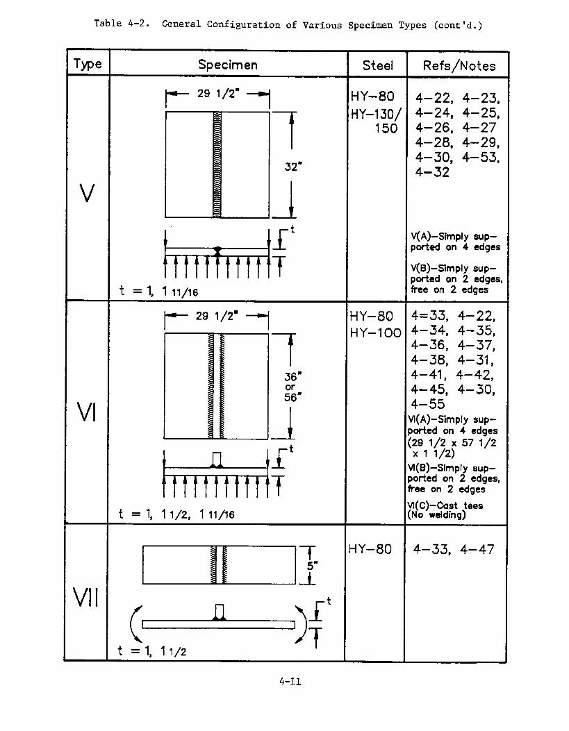
Table 4-2. General Configuration of Various Specimen Types (cent’d.)
Type Specimen Steel Refs/Notes
t-29 1/2”
~HY-80 4–22, 4–23,
7
HY-130/ 4-24, 4–25,150 4-26, 4–27
4-28, 4-29,4–30, 4-53,
32” 4-32
v 1I I
tV(A)-Simpiy sup-ported on 4 edges
H!HM! TV(B)-Simply sup-ported on 2 edges,
f = 1, 1 11/16 free on 2 edges
~ 2, 1/2” y HY-80 4=33, 4–22,
7
HY–100 4–341 4-35$4–36, 4–37,4–38, 4–31 ,
36” 4–41 , 4–42,
:6”4-45, 4–30,
VIJ
4–55Vi(A) -Simpiy sup-ported on 4 edges
if
t(:911(72; 57 1/2
Vi(B)-Simply sup-
ttHttt H ‘T
ported on 2 edges,free on 2 edges
t = 1, 1 1/2, 1 11/16Vi(C)-Cast tees(No welding)
ml’ ‘y-’o 4-33’4-47
‘“ (~)f’
t = 1, 1 1/2
4-11
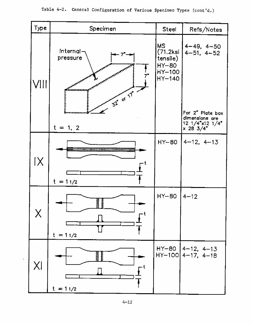
Table 4-2. General Configuration of Various Specimen Types (cent’d.)
Type Specimen Steel Refs\Notes
MS 4-49, 4-50Internal (71.2ksi 4–51, 4-52
pressure tens!le)
7HY–80HY-1OO
7“
Vlll 9HY-140
For 2- Plate boxdimensions are12 1/4”xl 2 1/4”
t =1,2 x 28 3/4”
HY-80 4–12, 4–13
lxI 1 I f
t
‘T
, :!_: ~1 ;–t t-lY-80 4-12
+++t = 1 1/2
/ HY-80 4-12, 4–13+ HY–loo 4–17, 4–18
xlt = 1 1/2
4-12
Table 4-2. General Configuration of Various Specimen Types (cent’d.)
Type Specimen Steel Refs\Notes
~11 ~ ‘Y-8” 4-’3
t I It
I
‘Tt = 1 1/2
HY–80 4-12, 4-13
~,1, ~ ‘Y-’oo
+++
t = 3/4, 1 1/2
A303B 4–55, 4–56,
t-- ‘7”7
70B 4-57
79 7/8”
{Iv -L
f
Htttttmsimply supportedplate 4 edges
1
xIV(A –Plain platexIV(B –Notched
t = 3/4 (Charpy-V)
4-13
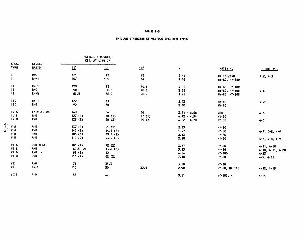
TABLE 4-3
FATI GUE STRENGTHSOF VARIIXJS SPECIMEU TYPES
FATIGUE STRENGTH,KSI,AT LIFE OF
SPEC.~
STRESSRATIO 105—
72100
MATERIAL
HY-130/150HY-80, HY-1OO
FIGURE NO.
4-2, 4-3
g
4.455.16
I1
R=(IR=-1
IIIIII
R=-1R=OR=+%
1289065.5
7250.536.2
40.528.320.2
4.003.983.92
liY-80, HY-100Hr-aor IIY-1OOIiY-80, HY-1OO
4-4
111[[1
R=- 1R=o
12790
4330
2.132.10
HY-80HY-80
4-20
IV AIv B[V B
(XIVA) R=OR=OR=O
?60127 (1)129 (2)
8678 (1)80 (2)
4647 (1)49 (2)
3.71 - 3.684.72 - 4.544.82 - 4.70
700HY-80HY-80
4-6
4-5
R=OR=OR=OR=O
137 (7)143 (2)106 (1)110 (2)
51 (1)44.5 (2)39.5 (1)43.5 (2)
2.33
1.97
2.33
2.48
HY-80HY-80HY-80HY-80
4-7, 4-8, 4-9
4-7, 4-8, 4-9
4-11, 4-204-10, 4-11, 4-204-234-5, 4-11
VBVB
VIkV[BVIBv]c
R=O (Est. )R=OR=OR=O
103 (2)68.5 (2)92 (2)
113 (2)
52 (2)33.6 (2)5282 (2)
3.373.234.047.18
ttY-80HY-80HY-?OOHY-80
VI1VII
R=OR=- 1
76110
35.350
3.002.90
HY-80HY-80, HY-14032.5 4-12, 4-13
4-14VIII Fl=o 845 47 3.11 HY-100, H
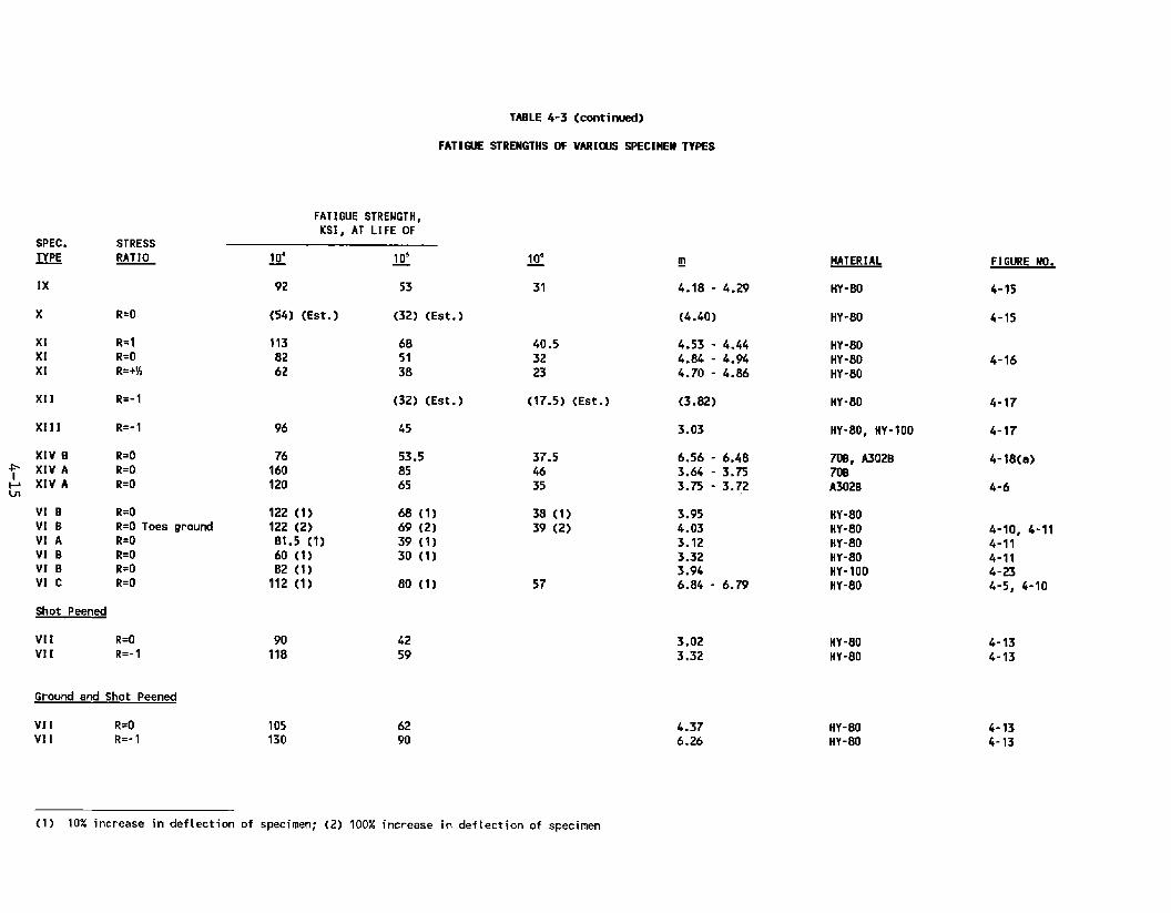
TABLE 4-3 (comti nued)
FATI = STRENGTHSOF VARIUJS SPEC[HEH TYPES
FATIGUE STRENGTH,KSI, AT LIFEOF
SPEC. STRESS~ RATIO
IX
10=— g ~
31 4.18 - 4.29
(4.40)
40.5 4.53 - 4.4432 4.84 - 4.9423 4.70 - 4.86
(17.5) (Est. ) (3.82)
3.03
6.56 - 6.483.64 - 3.753.75 - 3.72
3.954.033.123.323.946.84 - 6.79
HATERIAL FIGURE tJO.
4- ?5
4-15
92 53 tlY-80
x R=o (54) (Est. ) (32) (Est.) HY-80
XI R=1XI R=OXI R=+%
1138262
685138
HY-80MY-SOHY-80
4-16
X11 R=-1 (32) (Est. ) HY-80 4-17
4-17
4-18(a)
4-6
X111 R=- 1 96 45 HY-80, IIY-?OO
XIVB~ XIVA1A XIVAU!
VIBVIBW AVIBVIBVIC
R=OR=OR=O
76160120
53.5
85
65
70B, A302B70BA302B
37.54635
R=OR=O Toes ground
R=OR=OR=OR=O
122 (1)122 (2)81.5 (1)60 (1)82 (1)
112 (1)
68 (1)69 (2)39 (1)30 (1)
38 (1)39 (2)
tlY-80HY-80HY-80HY-80HY-1OOHY-80
4-1o, 4-114-114-114-234-5, 4-lo80 (1) 57
Shot Peened
VI1 R=OVI [ R=- 1
90118
4259
3.023.32
HY-80HY-80
4-134-13
Ground and Shot Peened
VI [ R=OVI [ R=- 1
105130
62
904.376.26
HY-80HY-80
4-134-73
—(1) 10% increase in defection of specimen; (2) 100% increase in defection of specimen

100
●
xoP
r
~-l,- .~--c‘Ym “ “
.& :* ‘Y ‘“i y‘.\ =--~
Stress Ratio R=O ‘< *>-L’>! “: ‘,
Stress Ratio R=-1Stress Ratio R=%MechanicallyPeened ‘Y”p >- ● “~
‘ k:’ -‘1
Fi~ure 4-4. S-N Curves for TypeII SpecimensofHY-80, HY-1OO and 1’Y-130/150Steels ‘-
‘\
~
*
-L@)_ ‘~100 ‘ ..~.
‘.~
● * : -----=. ‘ “------
●-. -4..
q Stress Ratio R=O -+ ~ ‘~x Stress Ratio R=-1
“‘G’~
Cycles to Failure
Figure 4-2. S-N Curves for Type I Specimens of HY+?O Steel
~... .———— ____ ____ ._..__ .1(33 104
~—- 1105 1oh

●
xo
P
Stress RatioStress RatioStress RatioMechanically
R=OR=-1 :-.% iR=++jpeened P P
“’~.o –-~
Figure 4-16. S-N Curves for Type XI Specimens of RY-80 andHY-1OO Steels
●x
● Stress Ratio R=O x wx Stress Ratio R=-1
● coma ●
Figure 4-3. S-N Curves for Type I Specimensof HY-80, HY-1OOand HY-130/150Steels
Cycles to Failure

x ● Life for 10% increasein deflectionA o Life for 100% increasein deflection
---
x and A are for cast tee sPeCimenS
Figure 4-5. S-N Curves for Type IVB Specimensof HY-80 SteelPlate andTypeVICof HY-80CastSteelatStressRatioR.o
0
Life for 10% increasein deflectionLifefoT 100% increasein deflectionFailureof XIVA of 70B steelFailureof XIVA of A302B steel
Figure 4-6. S-N15070B
Curves for Type IVB Specimensof 1-1/2”HY-130/Steel and Type XWA Specimensof 3/4” A302B andSteels at StressRatlo R=O
.- t103 1;4 105 ~@
Cycles to Failure

● Type VB specimens,HY-80x Type VA specimens,HY-80
● Type VBx Type VAo Type VBU Type VB
●
Specimensof HY-80Figure 4-8. S-N Curves for Type VA and VBSteel at StressRatio R=O (Lifeat 100% increasein deflection)
specimens,HY-80 :-
specimens,HY-80, HY-80, mechanicallypeenedspecimens,HY-130/150
\
. Peened-
Figure 4-7. S-Nand10%
Curves for Type VA and VB Specimensof HY-80HY-130/150Steels at StressRatio R=O (Life at
increasein deflection)
,.3 ]04 105
Cycles to Failure

● SpecimenType VB [4-22,4-27]A SpecimenType Vf![4-23] UndercuCl SpecimenType VB [4-23] Lack ofo SpecimenType ~[4-26] Weld tox SpecimenType VA [4-53]o SpecimenType VB [4-24]Rolled t
Figure 4-9. S-N Curvea for Type VA and VB Specimensof HY-80Steel at Stress Ratio R=O (Life at 100% increaseirIdeflection)
103 104 I05
Cycles to Failure

100
\
●
xP●
oDA
:
\. ●☛
❞❞
✝ ✍~%r+mnao~”o ●
As welded,VIBAs welded,VIA
Shot peened,VIFl●UI ● e
Mechanicallypeened,VI.BGround,VI13
o ● O
Cast steel, VIC
Stress relieved,VIB
Salt water corrosion
As welded,VIBAs welded,VIA (est.
Shot peened,VIB
Mechanicallypeened,Ground,VIBCast steel,VIC
, VIBFigure 4-10. S-N Curves for HY-80 Type VI SpecimensUnder
VariousTreatmentsat Stress Ratio R=O (Lifeatyo>.w - 10% increasein deflection)
k. ~e “ ~g. _ n
)
● *e ●
VIB
i
~ Stressrelieved,VIB Figure 4-11. S-N Curves for HY-80 Type V1l SpecimensUnderVariousTreatmentsat Stress Ratio R=O (Life at
~ Salt water corrosion,VIB 100% increasein deflection)
IL
Cycles to Failure
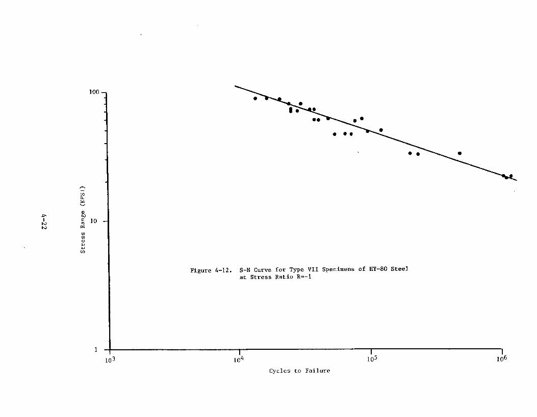
100
●
Figure 4-12. S-N Curve for Type VII Specimens of HY-80 Steelat Stress Ratio R=-1
I I I I103 ~04 105 106
Cycles to Failure

●
x
AA0+
GSPSP
As welded, R=OAs welded, R=-1Mechanicallypeened, R=OMechanicallypeened, R=-1Ground,R=OGround,R=-1Ground and shot peenedShot peened
(Lifeat 100% increase in deflection]
I Figure 4-13. S-N Curves for Tat Stress Ratios
x
“<,0 .

1000
● Boxes of 1“ plateo Box of 2“ plate
Figure 4-14. S-NCurve for Type VIII Specimensof Mild Steel, HY-80HY-1OO and RY-140 Steels at Stress Ratio R=O
10

● 0
/
u/
/
/
“e
u
‘*
u
4-25

100
OJuc2
100
10
● A302B
●
●●
●steel
x 70B steel3/4” plates
Figure 4-18(a). S-Nand
.\.
Curve for Type XIVB Notched Specimensof A302B70B Specimensat Stress Ratio R=O
Figure 4-18(b). Comparisonof Plain and Notched Type XIV Specimens
13 IJ4 J)5 166
Cycles to Failure

1000
100
lC
-.
Figure 4-19. Comparisonof Axial Fatigue of Type 111 Specimensand Bending Fatigue of Type VI and VII Specimensat Stress Ratios R=O and R=-1
—.1
3 104
Cycles
4.,1
I I105 ~06
to Failure

TABLE 4-4
HY STEEL TEST MEMBERSUSED TO INVESTIGATE MULTIAXIAL FATIGUE RESPONSE
Tv~e I. Axially loaded flat plate specimens in thicknesses of1/2, 3/4 and l-1/2-inch. Materials included are HY-80, HY-1OOand HY-130/150. The members have been studied under the stressratios of R=O and R=-l. The results of the tests are found inFigures 4-2 and 4-3.
Type II. These members are again flat plate members’ withtransverse butt welds and studied under axial loading inthickness of 3/4 and l-1/2-inches. Members included in thestudies are of HY-80 and HY-1OO steels and were subjected tostress ratios of R=O and R=-l, and R=+l/2. The results of thetests are found in Figure 4-4.
Type III. These are also flat plate specimens subjected to axialloadings and fabricated with transverse stiffeners welded to bothsurfaces of the plate with full penetration welds. Material was1-1/2 inches thick and test members fabricated of HY-80 and HY-100 steels.
Type IV. The type IV specimens consisted of flat rectangularplates that were subjected to transverse pressure therebyproducing a flexural loading of the plates. Type IVA specimenswere simply supported on four edges. In the case of type IVBmembers, the plates were simply supported on two opposite edgesand free on the remaining two edges. In this instance, most ofthe tests have been conducted on HY-80 or HY-130\150 steels. Theresults of the test can be fund in Figures 4-5 and 4-6.
Type V. These are flat plate members with transverse butt weldsthat were subjected to transverse bending loads and supportedeither on four or two edges of the plate. In these studies,primarily conducted on HY-80 and HY-130/150 steels, defects suchas undercut and lack of fusion were introduced in the welds. Theresults of these various studies can be found in Figures 4-7, 4-8and 4-9.
Type VI. These are flat type specimens which were simplysupported on either two or four edges of the plates and subjectedto a uniform transverse pressure. However, in this instance astiffener was welded to the surface of the plate with fullpenetration welds. In this instance most of the tests wereconducted on HY-80 and HY-1OO steels. However, a variety ofvariables have been included in the studies and cast steelspecimens have also been studied. The results of these variousstudies can be found in Figures 4-10 and 4-11.
4-28

TABLE 4-4 (continued)
HY STEEL TEST MEMBERSUSED TO INVESTIGATE ULTIAXIAL FATIGUE RESPONSE
Type VII. The Type VII members were beam-type plates on which atransverse stiffener had been welded with full penetration welds.Again, these members are fabricated of HY-80 steel and subjectedto a flexural loading which provided a stress ratio of R=l. In alimited number of tests a stress ratio R=O was also included.The toes of the fillet welds of these members were treated invarious ways including mechanically peening, grinding, and shot-peening. The results of these various tests will be found inFigures 4-12 and 4-13.
Tv~e VIII. These specimens consisted of box sections fabricatedof plates. The boxes were fabricated of mild steel, HY-1OO, andHY-140 steels. The various box members were subjected to astress ratio R=O. Only a limited number of tests of this typehave been conducted. Nevertheless, results of these varioustests are summarized in Figure 4-14.
Type IX. These members consisted of flat plates specimens with alongitudinal full penetration butt weld in the member. Resultsof tests on HY-80 steel are presented in Figure 4-15.
Tv~e X. These members consisted of flat plates with transverseattachments on the surfaces of the plate and attached with filletwelds. The tests on HY-80 steel are summarized also in Figure 4-15. However, only a very limited number of tests were conductedon such members.
Tme XI. These specimens consisted of flat plates subjected toaxial loadings and fabricated with a transverse attachment on onesurface attached with full penetration welds. Material was HY-80or HY-1OO steel and the members were subjected to stress ratiosof R=-l, R=O and R=l/2. Results of these various tests aresummarized in Figure 4-16.
TvPe XII. This specimen consisted of a flat plate withlongitudinal attachments fillet welded to the surface of theplate. Only one tests of this type was conducted on HY-80 steeland is summarized in Figure 4-17.
Type XIII. These specimens were fabricated as a cruciform T-joint. The flat plates were welded to a transverse bar with fullpenetration welds and the transverse bar subjected to a loadingnormal to the surface of the bar. Both HY-80 and HY-1OO steelswere used in these T-joints. The results of the few tests ofthis type are presented also in Figure 4-17.
4-29

TABLE 4-4 (continued)
HY STEEL TEST MEMBERSUSED TO INVESTIGATE MULTIAXIAL FATIGUE RESPONSE
Twe XIV. These specimens were flat plate members that weresubjected to a transverse pressure and simply supported on fouredges. These were smaller than the specimens discussed aboveunder Types IV, V and VI. They were also thinner plates, only3/4-inch thick. Nevertheless, they were loaded in a mannersimilar to some of the Type IV, V and VI flat plate specimens.In this instance, however, a Type XIVA member consists of a plainplate and a Type XIVB specimen Is plate notched on the surfacewith a (charpy-V) notch. These results of these various testswill be found in Figures 4-6 and 4-18.
4-30

4.3.1 Multiaxial Stress Fields
Tests of plain plates, butt-welded plates, flat plates withattachments, and welded boxes will be examined in detail toobtain a general indication of the effects of multiaxialstresses on the fatigue behavior of these t~es of structuralmembers.
Flat plate members will be discussed. Tests of Type I, TypeIVB and Type XIVA members can be examined to provide someindication of the effect of biaxial stresses on flat plates.The results of fatigue studies on these three types of membersare presented in the following tabulation. The detailed data(range of fatigue stress) are presented in Table 4-3 andFigures 4-2 through 4-6.
Fatigue Life of HY Steels
Fatigue Strength at Life ofType 104 cycles 105 cycles
I (HY-80) 120 ksi 72 ksiIVB* (HY-80) 127 ksi 78 ksiIVB* (HY-130\150) 194 ksi 104 ksiXIVA (70B) 160 ksi 85 ksi
* Fatigue strength for 10% increase in deflection.
From this tabulation, the axial fatigue strength (Type I) isslightly lower than the fatigue strength of the Type IVBplates in bending for HY-80 steel. The plates in bendingappear to have fatigue strengths 5 to 8% higher than that offlat plates subjected to axial loadings. However, when onecompares the fatigue resistance of the flat plates of HY-80and HY-130/150 steels, it is found that the fatigue resistanceof the higher strength steel is 33 to 53% higher for thehigher strength steel. Thus, the strength of the material hasa very significant effect on the fatigue resistance of theflat plates, a much greater effect than the difference foundwhen comparing the bending and axial loading of a givenmaterial.
A comparison of the fatigue behavior of the unwelded Type IVBand Type XIVA specimens gives an indication of the effect ofone axis bending versus biaxial bending in a flat plate. In
4-31

this instance, it is found that the fatigue resistance of 3/4-inch plate of the XIVA specimens was 9 to 26% greater thanthat of the type IVB specimens. However, the materialsdiffered in thickness, the XIVA specimens were 3/4-inch thickand the IVB specimens were l-1/2-inch thick and they were alsoof a different material. The IVB specimens were fabricated ofHY-80 steel with a tensile strength of 108 ksi whereas theType XIVA members were fabricated of 70B steel with a tensilestrength of 102 ksi. Nevertheless, it appears that flatplates subjected to a transverse loading had a somewhat higherfatigue strength when stijected to biaxial stressing than whensubjected to uniaxial stressing.
A second group of members examined consisted of flat plateswith a transverse butt weld which were subjected to transverseuniform pressure. These members, Type V, had a lower fatiguestrength than that of the plain flat plates of Type IV,previously considered. The S-N curves were also steeper thusindicating a more severe notch effect in the butt weldedmembers which produced the lower fatigue strength.
In the case of the Type V members, both A and B specimens weretested and thereby give some indication of the effect of abiaxial loading. As indicated in Figures 4-7 and 4-8, thebiaxial flexural loading again provided an increase in fatigueresistance. In this instance the fatigue strength of the TypeVA members was approximately 30% greater than that of the TypeVB members.
The third group of flat plate members subjected to lateralloadings were plates with transverse welded attachments(Type VI). The following tabulation presents the results ofthe Types IV, V and VI test specimens.
Fatigue Life of Different Details
Fatigue Strength at Life ofType 104 cycles 105 cycles
IV B 127 ksi 78 ksiVB 106 ksi 39.5 ksiVI B 60 ksi 30 ksiVA 137 ksi 51 ksiVI A 81 ksi 39 ksi
4-32

It is readily evident that the effect of butt welding and theaddition of welded attachments has a significant effect on thefatigue resistance of the flat plates subjected to transversepressures, the greater the stress concentration of the welddetail, the greater the reduction in fatigue resistance.
As in the case of detail Type V, it can be seen that thebiaxial stressing in the Type VI members (Type VIA vs. TypeVIB) again produced an increase in fatigue resistance ofapproximately 30%. This is a significant increase in fatigueresistance under the biaxial stressing condition.
Another evaluation can be made by comparing the Type III, TypeVI, and Type VII specimens. These include plates subjected tolateral loading, beams subjected to bending, and axialspecimens all of which have stiffeners attached to them.Stress ratios R=O and R=-1 were included for these three typesof members. A summary of the results is presented in Figure4-19. Here it may be seen that at approximately 40,000 cyclesof loadings, the fatigue resistance of the three types ofmembers are approximately equal. However, the Type IIIspecimens have a somewhat steeper slope to their S-N curve.This would suggest that the stress concentration for thedetail was somewhat more severe for this type of specimen thanfor the Type VI and VII specimens. It can also be seen thatthe fatigue resistance is approximately 50% greater under acompletely reversed stress cycle than it is for a O to tensiontype of stress cycle.
The fourth type of member to be considered is the welded boxof HY-1OO steel. These boxes, Type VIII, were subjected tointernal pressure and consequently stressed in a mannersimilar to the butt welded plates or plates with attachments,Types VA and VIA. The stresses in the longitudinal andtransverse direction of the boxes are in a ratio of 1 to 2.The results for the various series of tests on boxes are shownin Figure 4-14. Their behavior appears to have been quitesimilar to that of the stiffened plates, T~e VIA. The slopesof the S-N tunes appear to be quite similar and their fatiguestrengths comparable. The plain butt welded plates, Type VA,appear to have a somewhat higher fatigue strength. In oneinstance, a mild steel box (identified by M) was tested underinternal pressure and appeared to have a somewhat lowerfatigue resistance, as shown in the figure.
4-33

In summary, it appears that biaxial stressing in ratio ofapproximately 1 to 2 provides a fatigue strength on the orderof 25 to 30% greater than that of members stressed axially orin bending in only one direction.
4.3.2 Mean Stress
The effect of mean stress on the fatigue strength of thevarious types of specimens can most readily be studied byexamining the fatigue behavior of the members at variousstress ratios. In Table 4-5, data are available for variousstress ratios for details of Type I, II, III, VII, and XI. Asummary of the relative fatigue strengths of the members atvarious stress ratios and at lives of 104, 105, and 10G cyclesare presented. In this table it is evident that a significantdifference exists in the fatigue strengths at stress ratios of-1, 0, and +1/2.
A visual indication of the effect of stress ratio on fatiguestrength can be obtained from the fatigue diagram of Figure 4-20. Here the fatigue strengths for the various details, atvarious lives, have been plotted and clearly show the stressranges decrease significantly as the mean stress is increased.It appears that the fatigue resistance can be represented bythe following relationship.
F. = Fra(l-o.45R)
where F, = fatigue stress range at stress ratio, R.
F =t-o fatigue stress range for a stress ratio of
O (O-to-tension stress cycle).
R = stress ratio, ratio of minimum to maximumstress in the stress cycle.
In a similar study’ [4-5], a similar relationship was presentedexcept that the coefficient for R was somewhat smaller.Nevertheless, in both evaluations it is seen that the fatigueresistance is clearly affected by the mean stress to which themembers are subjected.
4*3.3 Stress Gradient
Relatively few data are available concerning the effect ofstress gradient on the fatigue resistance of welded members.Some data are available on small rotating beam specimens andare reported in various locations in the literature. For
4-34

TABLE 4-5
EFFECT OF MEAN STRESS ON FATIGUE STRENGTH OF VARIOUS MEMBERS
SPEC.TYPE
I
II
III
VII
XI
STRESSRATIO
R=O
R=-1
R=+l/ 2
R=O
R=-1
R=O
R=-1
R=O
R=-1
R=+1/2
R=O
R=-1
FATIGUE STRENGTHAT VARIOUS LIVES
104 105 106
1.0 1.0 1.0
1.30 1.39 1.49
0.73 0.72 0.71
1.0 1.0 1.0
1.42 1.42 1.43
1.0 1.01.41 1.43
1.0 1.01.45 1.42
0.76 0.74 0.72
1.0 1.0 1.0
1.38 1.33 1.27
NOTE : Values are the ratio of the fatigue strength at the stress
ratio shown to the fatigue strength at a stress ratio R=O.
4-35

!Sq
I\6Q
4-36

example, Reference 4-58 indicates that as the diameter of amember increases the fatigue resistance of the material can beexpected to decrease under a flexural loading. There areindications that up to a diameter or thickness of approximate-ly 6 inches, the fatigue resistance continues to decrease.Beyond that thickness or depth there is little or no furtherdecrease in fatigue resistance. This is in agreement with thefatigue resistance of 12-in. deep beams. The fatigue resis-tance of the beams is approximately the same as that ofaxially loaded plates of the same type of material, indicatingthat there is no stress gradient effect in the 12-in. beamtests.
If it is assumed that axially loaded members represent theflexural minimum fatigue resistance of deep members or thickmaterial where there is no stress gradient effect, then somegeneral indication of stress gradient effects can be obtainedby comparing the results of the data tabulated in Table 4-3.In Figure 4-19, data are compared for Type III, VI, and VIImembers. This comparison indicates that for a life ofapproximately 40,000 cycles there is no significant differencein fatigue resistance for the axially loaded members (Type IIIspecimens) and the plates and beams 1 l/2-inches thick thatare loaded in flexure (Type VI and VII specimens) . However,the S-N curves for the Type III specimens, members withattachments on both sides of the plate, have a steeper slopeand consequently a lower fatigue resistances at very longlives.
A similar comparison is shown in Figure 4-21 for butt-weldedplates under axial loading and flexural loading. Again, thereis a difference in slope of the S-N cumes. In this instancehowever, the S-N curve for the butt-welded plates subjected toflexural loading has a steeper slope than those for themembers loaded axially. It is evident that much moreinformation is required to evaluate the question of stressgradient, particularly where multi-axial stresses exist.
4.3.4 Residual Stresses
Another factor considered in this study is the effect ofresidual stresses on the fatigue behavior of the various typesof test members. The data presented in Figures 4-1o and 4-11clearly show that residual weld stresses had little or noeffect on fatigue life of Type VIB members; members that werestress relieved had approximately the same fatigue resistanceas members tested in the as-welded condition. This should beexpected for the short lives studied in the investigations.
4-37

10
Figure 4-21. Comparisonof Axial Fatigue of Type II Specimensand Bending Fatigue of Type VB Specimensof HY-80Steel
103 104
Cycles to Failure

However, members subject to lower stress ranges (long lives)stress relieving can be expected to have an effect on thefatigue resistance of welded test members. If compressiveresidual stresses are introduced they can have a beneficialfatigue effect on a member, even at the high stress rangesemployed in the tests reported herein. This can clearly beseen in the Figures 4-22 and 4-23 studies wherein test memberswere mechanically peened. This mechanical peening not onlyintroduced residual compressive stresses in the peened regionbut also changed the geometry at the toe of the weld wherethis mechanical peening was applied.
Detailed examination of the data in Reference 4-42, whereinmembers were mechanically peened and then stress-relieved,indicates that the stress-relieving treatment reduced thefatigue resistance because it removed compressive residualstresses. In the cases where a stress-relieving treatment wasapplied before mechanical peening a higher fatigue resistancewas obtained, indicating that the residual compressivestresses remained in the member after mechanical peening inthis latter case and the higher fatigue resistance resulted.
From the limited data available, it is evident that the effectof residual stresses on fatigue, whether in uniaxial ormultiaxial test, depends upon the sense of the residualstresses, their magnitude, and the magnitude of the appliedstresses.
4.3.5 Corrosion
Although corrosion could be a very important factor for shipstructures, relatively little information is availableconcerning the effect of salt water on the fatigue behavior ofweldments in ship steel. In Reference 4-22, three corrosiontests were conducted on Type VIB specimens. In these testssalt water produced about an 18% reduction in fatigueresistance and approximately 58% reduction in fatigue life ofthe test members. However, since these tests were conductedat a frequency of 20 cycles per minute, the test would onlyhave taken approximately 50 hours. This raises many questionconcerning the effects of corrosion under long life conditionsand also many of the other factors that are involved incorrosion fatigue. In Reference4-59, reference is made to many pertinent factors that affectcorrosion fatigue. These include such factors as temperature,oxygen content, electrolytic potential, load ratios, cyclicfrequency, etc. It is readily evident that much more needs tobe done to evaluate the effects of corrosion in fatigue.
4-39

n
● OXQ
III//
.
II 1“
I I 1 I 1
o
Lrl9
-4
!+
0*
uz
uo
mo
4-40

o200-l
b-0!=t-a
“
no
a
o
P-I.0

4.3.6 Geometry, Fabrication Treatment, Defects
It is well known that the geometry of welded structuralmembers has a significant effect on the fatigue behavior ofsuch members. This is readily evident in the fatiguestrengths tabulated in Table 4-3. Here it can be seen that ata life of 10s cycles fatigue strengths for a stress ratio R=Oare found to range from 32 to 54 ksi and for a life of 10Gcycles the fatigue strength range from 17.5 ksi to 57 ksi.Among the highest values are the results from tests on plainplate material and cast members for which the geometry is verysimple and with little or no stress concentration.
As noted previously and shown in Figures 4-22 and 4-23,mechanical peening the toes of welds can improve the fatigueresistance of a welded member. However, care must beexercised in evaluating such improvements since much of theimprovement obtained in the weldments shown in these figureswas a result of the residual compressive stresses produced bythe mechanical peening.
Grinding of the weld toes can also provide some benefit to thefatigue resistance. However, in this instance the improvementis a result of the improved geometry.
Another geometrical factor that may affect the fatiguestrength of structure weldments is their defect ordiscontinuity quality. In the case of a l/16-in. undercut inType VB and VIB specimens only a small reduction in fatiguestrength was observed. However, a lack of fusion was found toproduce a greater reduction (see Figures 4-9 through 4-11).See Reference 4-23.
4.3.7 Size - Thickness
In the investigations included this study, materials varyingin thickness from l/2-inch to approximately 1 5/8-inches wereincluded. Nevertheless, there appears to be relatively smalleffect of member thickness. This effect appears to beovershadowed by such other factors as tensile strength andmagnitude of stress applied in the tests.
An examination of thickness in fact was included for specimensof Type I, VI, VII, and VIII. In the case of the Type Ispecimens, plain flat plates subjected to axial loadings,thicknesses ranging from l/2-inch to 1 l/2-inches wereincluded. In the case of 3/4 and 1 l/2-inch specimens of HY80
4-42

steel, greater lives were obtained for the 1 l/2-inch materialthan for the 3/4-inch thick material when tested on a stresscycle O to 50 ksi. This is contrary to the generalobsemation often made that the fatigue resistance decreaseswith an increase in thickness. Upon examination of thestrength of the two material, it was found that the tensilestrength of the thicker material was approximately 8% greaterthan the tensile strength of the3/4-inch thick material. This no doubt accounts for theincreased fatigue resistance of the thicker material.
In the case the Type VI and Type VII specimens, relativelylittle information was available concerning the effect ofthickness and no firm conclusions could be drawn concerningthis factor.
For the Type VIII box type specimens, material 1 inch and 2inches in thickness were used in the tests. Neglecting thetensile strength of the materials it is found that boththickness provided approximately the same strength for thetest members. This may be seen in Figure 4-14.
4.3.8 Material $trenath
Material strengths ranging from mild steel to HY-130/150 steelhave been included in this study. These various materialshave been examined for a variety of specimen type and ingeneral it is found that the fatigue strength tends toincrease with the tensile strength. However, the relationshipof the fatigue strength to tensile strength is affected by avariety of other factors such as geometry, stress level, etc.
Combining the data for flat plate specimens of HY-80, HY-1OO,HY-130/150 steels and in thicknesses of l/2-inch to 1 l/2-inches, Reference 4-19, one finds that the ratio of fatiguestrength to tensile strength varies from values of 0.80 to0.40, depending upon the life of the member. As shown inFigure 4-15, the ratio of 0.80 is obtained for a life of20,000 cycles and the value of 0.40 at a life of 500,000cycles. The shortest lives, of course, are obtained at thehighest test stress levels and the longest lives at the lowertest stress levels. Thus , it would appear that the fatigue totensile strength ratio is primarily a function of themagnitude of stress to which its members are subjected, thisbeing a more important factor than the strength of thematerial or the thickness of the material.
4-43

The geometry of the specimens also becomes an extremelyimportant factor and may overshadow the effect of the tensilestrength of the material. It is evident that material doeshave some effect on the behavior of the members but otherfactors such as geometry and stress magnitudes play a muchmore important role.
4.3.9 Random Loadinq
While random loading has been proven to have a large effect onthe fatigue life of structures, to date little or no data areavailable concerning random loadings on members subjected tomultiaxial fatigue of the type considered in this study. Thetype of random loading distribution can have a large influenceon the effective stress used in the fatigue analysis. We alsoknow that marine structures are subjected to random loadingwhere principal stresses’ proportions are also random. Randomloading is a factor that must be strongly considered in anyfuture multiaxial fatigue testing.4.3.10 Stress Phasinq
In laboratory studies of multiaxial stresses the repeatedstresses are generally applied in a proportional manner, thatis, the proportions of flexure to shear is constant or theproportion of tension or flexure to torsion is constant.However, in marine structures such as a ship or an offshoreplatform, proportions will vary. Consequently, in a stiffenedlaboratory beam, for example, the direction of principalstress at a given point in the beam will remain constant eventhough the magnitude of the loading is changed. In marinestructures that are subjected to varying flexural andtorsional loads, the magnitudes and directions of theprincipal stresses will change with time.
To date there does not appear to be any information availableconcerning the above types of stress phasing in weldedstructural details. However, considerable research has beenconducted on notched specimens as discussed in Section 3.2.Until such information becomes available for welded details itwill probably be necessary to consider the fatigue of suchstructural details in terms of the maximum principal tensilestresses without consideration of the oscillation or rotationin the direction in which such stresses might be applied.
4-44

5.0 EVALUATION OF MULTIAXIAL FATIGUE RELIABILITY
The evaluation of multiaxial fat@ue reliability was performedto quantify the effects of multiaxial fatigue and with thepurpose of developing a baseline to be used in judging overallimprovements in reliability through the use of multiaxialfatigue design procedures. The effort included a review ofexisting reliability formats and data to develop a baseline tojudge overall improvements in reliability by using multiaxialfatigue design procedures in marine structures.
5.1 RELIABILITY FORMAT FOR EVALUATING MULTIAXIAL FATIGUE INMARINE STRUCTURES
The purpose of engineering design is to ensure the safety orperformance of a given system for a given period of timeand/or under a specified loading condition. The absolutesafety of the system cannot be guaranteed due to the number ofuncertainties involved. In structural design, theseuncertainties can be due to randomness of loads, simplifyingassumptions in the strength analysis, material properties,etc. However, through probabilistic analysis we can limit therisk of unacceptable consequences. The major benefit of areliability-based design approach which utilizes probabilisticanalysis is that a designer will be able to generate anengineering system which is both efficient and reliable to thelevel specified or desired.
The concepts of the reliability approaches for most types ofstructures are relatively simple, but complexity is associatedwith execution of the procedure.
In general, the structural reliability problem can beconsidered as one of load and resistance. Failure occurs whenthe supply (the resistance or strength of the system) is lessthan the demand (the loading of the system). For a structuralsystem, this can be stated as:
Probability of Failure = Pj = P (strength < load)
If both the load and strength are treated as random variables,then the reliability problem can be treated usingprobabilistic methods. In order to perform a reliabilityanalysis, a mathematical model which relates the load andresistance must be derived. This relationship is expressed inthe form of a limit-state equation. For the simple case usedabove, it would appear as
g(x) =R-L
5-1

where R and L are the resistance and load effect randomvariables. Failure is represented by the region where g(x) isless than zero while the safe region is where g(x) is greaterthan zero. The line g(x) = O represents the boundary betweenthe regions and is thus defined as the limit-state equation.
The implementation of reliability-based design methods doesnot mean that all engineers and designers need to be deeplyversed in probability theory. Rather, the design criteriathey used should be developed in a format which is bothfamiliar to the users and which should produce desired levelsof uniformity in safety among groups of structures. Thisshould be accomplished without departing drastically fromexisting general practice.
One of the more popular formats for including probabilisticinformation in structural design is the Load and ResistanceFactor Design (LRFD) approach as recommended by the NationalBureau of Standards [5-1]. This approach uses loadamplification factors and resistance reduction factors(partial safety factors) and can be expressed as:
where R is the resistance, e.g. in flexural shear, fatigue,etc.; L, is the ithload effect, e.g. due to dead, live, wind,earthquake loads, etc. ; @ is the resistance reduction factor;.5,is the ithpartial load effect amplification factor; and nis the total number of load effects considered in the limit-state design equation.
The implementation of an LRFD format for reliability-basedfatigue design has been proposed by Albrecht [5-2], Ang [5-3],and Munse [5-4] for cumulative damage fatigue approaches andby Wirsching [5-5) for the fracture mechanics approach tofatigue propagation.
For fatigue cumulative damage estimates of structures, theresistance is usually represented in terms of the mean andstandard deviation of the number of cycles to failure at agiven stress range. This information is typically derivedfrom constant amplitude fatigue tests data for specimens orcomponents being investigated. According to this approach, anumber of these tests are conducted and the results are
5-2

provided in the form of stress range versus life (S-N) curves.The question arises whether an equivalent stress or strainapproach based on small component tests simulating the loadeffects of the complex joint can be used to reduce the scatterabout the mean line, thus reduce conservatism and improvereliability of the structure.
Before this question can be answered, it is beneficial toreview the reliability formats in greater detail to illustratethe role of fatigue data bias and scatter in the reliabilityformats.
The standard deviation of the fatigue life data can be found.However, the scatter of the data about the mean fatigue lineis not the only uncertainty involved in the S-N analysis. Ameasure of the total uncertainty (coefficient of variation) infatigue life, V~, is usually developed to include theuncertainty in fatigue data, errors in the fatigue model, andany uncertainty in the individual stresses and stress effects.
Ang [5-3] and Munse [5-4] suggested that the total COV interms of fatigue life could be given by:
VR2 = V.2+ V~2+ VC2+ (mV.)2
where:
v, = total COV of resistance in terms of cycles tofailure
VN = variation in fatigue test data about mean S-N1ine
v, = variation due to errors in fatigue model anduse of Miner’s rule
Vc = variation due to uncertainty in mean interceptof the regression line; includes effects offabrication, workmanship, and uncertainty inslope
v~ = variation due to uncertainty in equivalentstress range; includes effects of error instress analysis
m = slope of mean S-N regression line.
5-3

Values of m and V~ can be obtained from sets of S-N curves forthe type of detail being investigated; a number of which aretabulated by Munse [5-4].
Reasonable values for the remaining uncertainties areavailable in the literature [5-3 through 5-8]. Typically, V~is taken to be 0.1, VC is assumed to be 0.4, and V~ is taken as0.15.
As can be seen from the discussion, there are many moreuncertainties other than V~ for scatter. However, this iswhere the primary improvement in reliability will be derivedwhen using multiaxial fatigue design procedures. Typically,COV for scatter V~ is .6 for welded structural details.
To determine the relationship between load and resistance forfatigue analysis, the value of COV for scatter in fatigue lifemust be converted to total COV of resistance in terms ofstress range. Using the properties of log-normal distribu-tions, resistance transformation in terms of stress range isgiven by
v/= [[(l+ V:F]-l] 1’2
Reiterating the reliability equation where
where the load and resistance factors,are expressed in terms of stress range
Y = exp (6J3VJ)
@ = exp (-&13VR’)
where 15= a splitting function and Bprobability of failure [5-9].
The reliability equation can also be
Y and O, respectively,and can be given by
is an acceptable
used to establish a levelof reliability-for fracture mechanics fatigue crack growthmethodologies. Again, there are numerous uncertaintiesincluding initial flaw size, type and orientation,experimental procedures, and geometry of structurefew. These, of course, contribute to the bias and
5-4
effects ofto name ascatter of

the crack growth rate parameters on the Paris equationdiscussed in Section 2.
5.2 RELIABILITY OF MULTIAXIAL FATIGUE RESEARCH
With this background we now have a basis for comparingmultiaxial fatigue data to existing approaches and determineif there are improvements in bias and scatter resulting inmore reliable designs.
The British Department of Energy (DOE) [5-10] publishedfatigue design rules for offshore structures. Reliabilitydata is presented for T-joint and S-N cume and is said to beapplicable to other complex joints as well. The standarddeviation of special interest is the use of principal stressand maximum shear stress at the hot spot rather than stressnormal to the weld toe as applicable to the API rules [5-11]where the standard deviation is on the order of 2 or more.The resulting improvement in standard deviation is apparent byusing a combined stress.
Nokleby [5-12] reviewed criteria for prediction of high cyclefatigue under multiaxial stress conditions includingoctahedral stress criterion, shear stress criterion, internalfriction criterion and shear stress intensity criterion. Thetests were conducted on smooth steel specimens with theresults as follows.
Criterion Bias Cov %
Octahedral stress 1.021 9.2Shear stress 1.080 9.5Internal friction 1.023 6.8Shear stress intensity 1.018 6.4
A positive bias indicates a conservative prediction andmeasurement value. From the paper, it appears that the biasof all four methods are on the consemative side most of thetime.
Munse [5-4] investigated the fatigue initiation and crackgrowth in stiffened plate beam similar to CVK or web frames inship structures. An S-N curve is presented in which themaximum bending stress on the extreme fiber at the location offailure is used to correlate data. These data are shown inFigure 3-27. It is apparent from this comparison that themaximum bending stress at the fracture section does notprovide a consistent relationship in these tests either. A
5-5

much better correlation is obtained when the data are analyzedon the basis of the maximum principal tensile stress(including the effect of shear) at the point of failure. Dataplotted on this latter basis are presented in Figure 3-28.Although there is still scatter in the test results, there isa well-defined scatter band for the entire range of lives.
It appears that the shear and flexural stress in the web ofthe welded members and the resulting principal tensilestresses, along with stress concentration gradients atstiffener welds, produce the most critical fatigue conditionin the weldments with various stiffeners.
Moyar and Garg [5-13] re-analyzed Munseis plate beam data andcorrelated the data using maximum principal stress, modifiedmaximum range of shear stress, and the maximum octahedralshear stress criteria.
A comparison of the corresponding predictions for the threetheories versus the observed cycles to failure for the type Bbeam specimens is provided in Table 3-4. The mean andstandard deviation of the difference of predicted minusobserved cycles to failure are presented. The maximum shearrange theory appears more satisfactory in that the meandifference in prediction and observation is smaller. Overall,the maximum principal stress theory is the least conservative.
Yung and Lawrence [5-14] evaluated multiaxial fatigue designprocedures for tube plate welds under combined bending andtorsion. The multiaxial fatigue theories of Lohr and Ellisonand Kandil, Brown and Miller gave reasonable non-consenativeestimates of fatigue life. Table 3-5 presents the fatiguelife data and results of predictions. As indicated, the meanvalues for maximum shear strain are in best agreement withexperimental results. The COV was not calculated, howeverFigures 3-31 through 3-33 illustrate the scatter in data.Although there are differences in bias for each approach, thescatter is similar for the limited number of points shown.
Lawrence et al [5-15] presented reliability data for theirInitiation-Propagation approach for predicting fatigue life ofwelded details. He compared his approach with that of Munsetsand others. The comparison is very interesting in that itshows the potential gains in predicting the stressdistribution at the weld toe versus nominal stress in thestructural member as is done in Munse’s approach. However,there is a key tradeoff between the additional work requiredto predict that combined stress at the weld toe and having
5-6

stress data presented as nominal stress with additionalinherent data scatter. Also, Lawrence had the advantage ofknowing the notch stress concentration factors of his weldedspecimens -- an item not known to structural designers. Thisissue is central to the need for multiaxial fatigue researchand the possible gain in reliability versus ease of use fordesigners.
5*3 EVALUATION OF MULTIAXIAII FATIGUE RELIABILITY FOR MARINESTRUCTURES
To put these coefficients of variance data in perspective, itis helpful to estimate the effect on total reliability orsafety factor for gains in reliability from using multiaxialtechniques. The LRFD format presented by Noland and Albrecht[5-7] is used to make this example relatively simple and easyto follow rather than using more complex variations. The netinput will be similar to other techniques by using
v= = .1
Vc = .4v, = . M
and varying V. (scatter of S-N data).
The impact of total reliability becomes clear. As shown inTable 5-1, large improvements in coefficient of variance indata scatter produce relatively small changes in totalreliability. This small change results because the magnitudeof COV for the other factors or uncertainties in the totalproblem of fatigue in marine structures. In other words,there are many large uncertainties in the overall problem. Alarge improvement in one parameter only produces a small neteffect. This finding strongly suggests improvements should bemade across the board rather than singly. This conclusion isnot completely fair because if a multiaxial fatigue procedurewere used it is likely that other uncertainties would beimproved. For example, the level of accuracy in stressprediction is likely to be greater, helping to improve theoverall level of reliability.
Nevertheless, this is a good illustration of the potentialoverall benefit if multiaxial fatigue procedures are used.
On a more deterministic note, one of the original questionsoften asked by structural designers is how to characterize thecomplex stress distribution for fatigue analysis. With
5-7

TABLE 5-1
POTENTIAL IMPROVEMENTS IN OVERALL RELIABILITYUSING MULTIAXIAL FATIGUE PROCEDURES
% of % ofv“ VR2 VR ‘ @ +/7 API Munse/DOE
MAF .25* .385 .143 .723 2.07 33 10
Munse/DOE .6 .703 .184 .653 2.3 20
API 1.3 2.033 .27 .545 2.75 -
* Representative value based on data presented for welded plate beams
and welded tube plate connections.
5-8

implementation of the research program described next, theseanswers will be provided.
5-9


General multiaxial fatigue research has been investigated forsimple welded structures by several researchers. There areindications that multiaxial fatigue approaches are capable ofimproving fatigue design in marine structures. However,additional effort is required to fully characterize multiaxialfatigue response in marine structures to a level of accuracybeyond existing techniques that are based on component tests andnominal stress fields. The vast majority of multiaxial fatiguedesign procedures were developed for unwelded structures wherestructural loading is not as complex as for marine structureswhere principal stresses and mean stresses are random -- a factorunaccounted for in most multiaxial fatigue procedures.
Implementation of this technology should certainly not be limitedto component testing arena. There will be many “spin-offs” fromthe advances made or anticipated in multiaxial fatigue research.For example, engineering design relies heavily on analyticalprocedures such as finite element analyses to aid the design andtesting procedures. The results of these analyses are oftenquite detailed and may be the input to fat@ue life predictionsmade prior to construction. Redefining the critical parametersnecessary for fatigue life predictability will certainly affect alarge base of existing software, not to mention the actualanalytical procedures. The designs that are complex enough torequire finite element rnodeli.ngmay be the very applications thatrequire a fatigue life predictive approach using other than theexisting component-based criteria.
Additionally, the approach must be used in conjunction withpredictive techniques that are capable of predicting stresscharacteristics in the weld regions in great detail. While thereis a trend toward detail in stress predictions, there isconsiderable additional effort. The designer must choose theapproach which best fits the design application and stressconditions. Similarly, when detailed fitness for serviceassessments are conducted, these multiaxial approaches will bequite useful, especially fracture mechanics approaches thataccount for mixed mode Stage I crack growth.
6.1 CONCLUSIONS
Conclusions on the multiaxial fatigue approaches are outlinedbelow. These conclusions are presented to summarize the findingscited above and to form a basis for further researchrecommendations.
1. There is currently no universal parameter for correlatingcyclic multiaxial stress/strain with fatigue life formarine structures. Very few have been investigated forwelded joints as a group and additional validation
6-1

efforts are required before they can be recommended for
2.
3.
4.
5.
general application to marine structures.
Of the correlation approaches reviewed, the effective orequivalent criteria such as use of maximum shear stressfor crack initiation and maximum principal stress forcrack growth are found to be potentially useful tools forextrapolating materials’ responses from one stress stateto another and for life correlation in high cyclemultiaxial regimes and appear to be suitable forpredicting fatigue initiation and propagation in simpleweld configurations (e.g., butt welds in laterally loadedplates). However, additional research is required beforethese approaches may be integrated into a designapproach.
There are a number of factors whose influence must bequantified and validated before multiaxial techniques canbe applied to welded details with acceptable levels ofconfidence. These factors include: mean stress, residualstress, stress gradients, and random load and phasingeffects.
There is currently insufficient data to determineconclusively if there is a significant improvement infatigue reliability (bias and scatter) over techniquessuch as Munsels approach presented in SSC-318 or the UKDOE code for offshore structures. By characterizingdetailed stress distributions on a local level,additional variables are added that are unquantified andincrease uncertainty in overall levels of reliabilityeven though the state of stress may be known on a detaillevel. From a deterministic perspective the equivalentstress correlations (e.g. principal stress) are usefulfor structural analysts interested in predicting stressesin welded details; however, many other variables must beconsidered in any multiaxial fatigue analysis.
The stress dktributi.ons h ship structural detailsexamined as part of this study are located in stressfields where axial primary stress dominates the principalstress field. There are secondary biaxial stress effectsat frames and floors. Cutouts produce axial stress atthe free surface in the global biaxial stress fields.The principal stress phase relationship k random. Onthe other extreme, offshore structures have complextubular joint configurations subjected to multiaxialstresses and strains with varying out of phase principalstress fields.
6-2

6. Both ships and offshore platforms experience both aconstant mean stress (e.g. dead load from structuralweight) and varying mean stresses that have not beenaccounted for in existing fatigue design procedures, letalone for multiaxial approaches.
7. Eventually, more extensive characterization of timedependent multiaxial loading spectra of actual marinestructural components will be useful in directing theapplication oriented research efforts.
6.2 RECOMMENDED MULTIAXIAL FATIGUE RESEARCH
Designers of marine structures need information on the fat@ueresponse of complex welded details under loading conditions withvariable time-dependent principal stress. Based on the review ofmultiaxial fatigue it is concluded that, while there arepotentially useful tools available, none have been developed orvalidated to an extent that will provide a reliable designwithout extensive component testing or analysis.
Although multiaxial fatigue technology has been developed forrelatively simple structures this technology will not transferdirectly to complex marine structures. Additional research isrequired to validate multiaxial fatigue technology for marinestructures. The first step in the research program is to definethe stress parameters ~ primarily in ship structures; to conductfollow on tests based on realistic stress conditions.
6.2.1. DEFINE SPACIAL AND TEMPORAL CHARACTERISTICS OF PRINCIPALSTRESSES IN SHIP AND OFFSHORE WELDED DETAILS.
Principal stress characteristics and their phase relationshipshave been shown to have a substantial influence on multiaxialfatigue response and the selection of appropriate predictiontechn@ue. These characteristics must be fully defined beforemultiaxial fatigue technology can be validated for use in marinestructures.
The characteristics of principal stresses include magnitudes,phase relationships, gradients and mean stress components. Therandom nature of each shall be considered. Thesecharacteristics shall be identified for typical structuraldetails including a bottom plate butt weld, a C!VKbracket and alongitudinal cut out for ships and multiplaner KT joints withoverlapping and non-overlapping members for offshore structures.
6-3

Typical loading conditions shall be identified and applied to themarine structure and detailed stress calculations shall beperformed to a level of detail required to support nominal stressand crack growth studies.
6.2.2 CONDUCT MULTIAXIAL FATIGUE TESTS ON MARINE STRUCTURALDETAILS
Multiaxial fatigue testing should be conducted to validateapproaches using representative stresses and strains identifiedin the previous project.
This effort should be conducted to validate multiaxial fatigueapproaches in marine structures based on their unique loadingcharacteristics. The best approach will likely depend on thespecific structure considered. Even in marine structures as agroup, principal stress characteristics are different. Theassociated multiaxial fatigue approach will reflect the stresscharacteristics identified. Fatigue initiation and crack growthtests shall be conducted. Sufficient tests shall be conducted toestimate bias and scatter for integration into reliabilitystudies. Analytical correlation shall be conducted to validatethe various multiaxial fatigue techniques that apply to marinestructures including stress and strain based fatigue lifecriteria and crack growth criteria (e.g. K.~~). Studies shouldconcentrate on the high cycle fatigue range.
6.2.3 INTEGRATE MULTIXXIAL FATIGUE RESEARCH INTO A RELIABILITYBASED FORMAT
The objective of this research is to develop analyticalapproaches for predicting multiaxial fat@ue response in marinestructures. The approaches will likely be different depending onthe marine structural detail. A decision tree or expert systemmay be appropriate. The tasks for this project should bedeveloped as part of the project described above.
6-4
1-1.
1-2.
1-3.
1-4.
1-5.
1-6.
1-7.
1-8.
2-1.
2-2.
2-3.
Buckley, W.H., “Progress in the Development of StructuralLoad Criteria for Extreme WavesrJ, Extreme LoadsSymposium, SNAME, SSC, 1981.
Ochi, M.K., “Principles of Extreme Value Statistics andTheir ApplicationII, Extreme Loads and Response Symposium,SNAME, SSC, 1981.
White, G.J. and B.M. Ayyub, “Reliability Based FatigueDesign for Ship Structurest~, ASNE Journal, May 1985.
Stambaugh, K. and W. Wood, IiShipFracture MechanismsInvestigation”, Final Report for SSC, March 1987.
Thayamballi, A., Y-K Chen and D. Lin, IiFractureMechanicsBased Assessment of Fatigue Reliability in ShipStructuresil, Ship Structures Symposium, 1984.
Munse, W.H., T.W. Wilbur, M.L. Tellalian, K. Nicoll andK. Wilson, “Fatigue Characterization of Fabricated ShipDetails for Design’!,Report No. SSC-318, Department ofCivil Engineering, University of Illinois at Urbana-Champain, sponsored by the Ship Structure Committee,1983.
American Petroleum Institute, ‘rRecommended Practice forPlanning, Designing and Constructing Fixed OffshorePlatforms”, API RP2A, 7th edition, January 1976.
British Department of Energy (UK DOE), “Fatigue DesignGuidance for Steel Welded Joints in Offshore Structuresll,London HMSO, 1984.
Liu, D. and A. Bakker, “Practical Procedures forTechnical and Economic Investigations of Ship StructuralDetails,” Marine Technology, January 1981.
Fricke W. and H. Daetzold, “Application of the CyclicStrain Approach to the Fatigue Failure of Ship StructuralDetails,” Journal of Ship Research, September 1987.
Munse, W., “Fatigue Characterization of Fabricated ShipDetails for Design,~I SSC-318, 1983.
R-1
2-4. Stambaugh, K. and B. Wood, “SL-7 Research Program SummaryConclusions and Recommendations, ilSSC 313, 1981.
2-5. Stambaugh, K. and W. Wood, IIship Fracture MechanismsInvestigationt’, Final Report for SSC, March 1987.
2-6. Chen, Y., J. Chin and A. Thayamballi, “Validation ofFatigue Life Prediction Using Containership Hatch CornerStain Measurements,” SNAME Trans, 1986.
2-7. Gulati, K.C., W. Wang and D. Kan, “An Analytical Study ofStress Concentration Effects in Multibrace Joints UnderCombined Loading,” OTC 4407, 1982.
2-8. Marshall, P., “Limit State Design of Tubular connectors,”Behavior of Offshore Structures, the Norwegian Instituteof Technology, 1976.
2-9. Marshall, P., ‘rBasicConsiderations for Tubular JointDesign in Offshore Construction,ll Welding ResearchCouncil Bulletin 193, April 1974.
2-10.Rodabaugh, “Review of Data Relevant to the Design ofTubular Joints for Use in Fixed Offshore Platforms,”Welding Research Council Bulletin 256, January 1980.
2-11.Bea R. G., !’Reliability of Marine StructuresFundamentals” prepared for SSC seminar on reliabilityFebruary 1988.
2-12.Miner, M.A., “Cumulative Damage in Fatigue”, Journal ofApplied Mechanics, Vol. 12, 1945.
2-13.American Petroleum Institute, IiRecommended Practice forPlanning, Designing and Constructing Fixed OffshorePlatforms”, API RP2A, 7th edition, January 1976.
2-14.American Welding Society, “Design of New TubularStructures”, Section 10 of D1.1, 1975.
2-15.British Department of Energy (UK DOE), ‘lFatigue DesignGuidance for Steel Welded Joints in Offshore Structures”,London HMSO, 1984.
2-16.Potvin, A.B., J.G. Kuang, R.D. Leick and J.L. Kahlich,“Stress Concentration in Tubular Joints”, Society ofPetroleum Engineers Journal, August 1977.
R-2

2-17.Marshall, P.W., Limit State Design of TubularConnections ‘t,Behavior of Offshore Structures, TheNorwegian Institute of Technology, 1976.
2-18.M.W. Kellogg Co., “Design of Piping Systems”, 2ndEdition, Wiley, 1956.
2-19.Bijlaard, P.P., “Stresses from Local Loadings inCylindrical Pressure Vesselsl~, Trans. ASME, August 1955.
2-20.Kuang, J.G., A.B. Potvin and R.D. Leick, llStressConcentration in Tubular Jointsff, Seventh Annual OffshoreTechnology Conference, OTC Paper No. 2205, 1975.
2-21.Wordsworth, A.C., “Stress Concentration Factors at K andKT Tubular Joints,!! Paper 7, Fatigue on OffshoreStructural Steel, Institute of Civil Engineers, 1981.
2-22.Gibstein, M.D., “Parametric Stress Analysis of T Joints,”Paper 26, European Offshore Steels Research Seminar, TheWelding Institute, November 1978.
2-23.Beale, L.A. and A.A. Toprac, “Analysis of In-Plane T, Y,and K Welded Tubular Connections”, WRC Bulletin 125,October 1967.
2-24.Reber, J.B., “Ultimate Strength Design of TubularJoints”, Fourth Annual Offshore Technology Conference,OTC Paper No. 1664, 1972.
2-25.Visser, W., “On the Structural Design of Tubular Joints”,Sixth ..~nual Offshore Technology Conference, OTC PaperNo. 2117, 1974.
2-26.Caulkins, D.W., ‘lParameter Study for Frameti ElasticStress in Tubular Joints”, Shell Oil Company,Construction-Design Group, New Orleans, IA, CDG Report15, September 1966.
2-27.Sikora, J.P., A. Dinsenbacher and J.E. Beach, “A Methodfor Estimating Lifetime Loads and Fatigue Lives for SWATHand Conventional Monohull Ships”, Naval EngineersJournal, ASNE, May 1983, pp. 63-85.
2-28.White, G.J. and B.M. Ayyub, “Reliability Based FatigueDesign for Ship Structures”, ASNE Journal, May 1985.
R-3

2-29.Park Soko, F.V. Lawrence, “Fatigue Characterization ofFabricated Ship Details for Design, Phase IIi~,Departmentof Civil Engineering, University of Illinois, for theShip Structure Committee, 1988.
2-30.Thayamballi, A., Y-K Chen and D. Lin, ‘~FractureMechanicsBased Assessment of Fatigue Reliability in ShipStructures”, Ship Structures Symposium, 1984.
2-31.Rhee, H.C., “Application of Finite Element AlternatingMethod to Offshore Stnctural Fatigue Analysisl~, OTC5111, 1986.
2-32.Huang, X., ‘IAFinite Element Evaluation of the StressIntensity Factors of Surface Cracks in a Tubular Joint!’,OTC 5665, 1986.
2-33.Liu, D. and A. Bakker, “Practical Procedures forTechnical and Economic Investigations of Ship StructuralDetails,” Marine Technology, January 1981.
2-34.Stambaugh, K.A., D.L. Edinberg, G.E. Fenton and P.R. VanMater, Jr., I!StructuralAnalysis of the Island ClassPatrol Boats”, for USCG Avery Point, CT, December 1988.
3-1. Rolfe, S.T. and J.M. Barsom, “Fracture and FatigueControl in Structures. Applications of FractureMechanics”, Prentice-Hall, Inc., 1977.
3-2. Forsyth, P.J.E., “Exudation of Material from Slip Bandsat the Surface of Fatigued Crystals of an Aluminum-CopperAlloy’!, Nature, Vol. 171, 1953, pp. 172.
3-3. Cottrell, A.H. and D. Hull, “Extrusion and Intrusion byCyclic Slip in Copper”, Proceedings of the Royal Society(London), Vol. 242a, 1957, pp. 211.
3-4. Fine, M.E. and R.O. Ritchie, IiFatigue-Crack Initiationand Near Threshold Crack Growth”, Fatigue andMicrostructure, ASM Materials Science Seminar, St. Louis,MO, 1978, pp. 245-278.
3-5. Laird, C., llMechanisms and Theories of Fatigue”, Fatigueand Microstructure, ASM Materials Science Seminar, St.Louis, MO, 1978, pp. 149-203.
3-6. Boettner, R.C., C. Laird and A.J. McEvily, I!CrackNucleation and Growth h High-Strain - Low Cycle
R-4

3-7.
3-8.
3-9.
Fatigue”, Transactions of the Metallurgical Society,AIME, Vol. 233, 1965, pp. 379-387.
Forsythe, P.J.E., “A TWO Stage Process of Fatigue CrackGrowth~l, Proceedings of the Symposium on CrackPropagation, Cranfield, England, 1961.
Fash, J.W., N.J. Hurd, C.T. Hua and D.F. Socie, ‘iDamageDevelopment During Multiaxial Fatigue of Unnotched andNotched SpecimensIi, Low Cycle Fat@_ue, ASTM STP 942, H.D.Solomon et al, Eds., ASTM, 1988, pp. 874-898.
Mason, W., “Alternating Stres Experiments”, Proceedingsof the Institution of ~echanical-Engineers- (Br.), -February 1917, pp. 121-196.
3-10.Mason, W. and W.J. Delaney, “Alternating Combined StressExperimentsii, British Association for the Advancement ofScience, London, 1921, pp. 329-341.
3-11.Gough, H.J. and H.V. Pollard, “The Strength of MetalsUnder Combined Alternating Stresses”, Proceedings of theInstitution of Mechanical Engineers (Br.), Vol. 131, No.3, November 1935, pp. 3-54.
3-12.Gough, H.J. and H.V. Pollard, “The Effect of SpecimenForm on the Resistance of Metals to Combined AlternatingStresseslt, Proceedings of the Institution of MechanicalEngineers (Br.), Vol. 132, December 1936, pp. 549-573.
3-13.Gough, H.J. and H.V. Pollard, ‘iProperties of SomeMaterials for Cast Crankshafts with Special Reference to
Combined Stressestt, Proceedings, Institution ofAutomobile Engineers (Br.), Vol. 31, March 1937, pp. 821-893.
3-14.Gough, H.J., H.V. Pollard and W.J. Clenshaw, “SomeExperiments on the Resistance of Metals to Fatigue UnderCombined Stress”, Aeronautic Research Council (Br.), R&M2522, 1951.
3-15.Guest, J.J., “Combined Stress. A Criticism of the Goughand Pollard Law”, The Automobile Engineer, September1937, pp. 326-332.
R-5

3-16.Guest, J.J., ItRecentResearch on combined Stress”rProceedings of the Institution of Automobile Engineers(Br.), Vol. 35, December 1940, pp. 33-72, 146-171.
3-17.Tipton, S.M. and D.V. Nelson, l~Fati~e Life Predictionsfor a Notched Shaft in Combined Bending and Torsiont’,Multiaxial Fatigue, ASTM STP 853, K.J. Miller and M.W.Brown, Eds., Am. Sot. for Testing and Materials, 1985,pp. 514-550.
3-18.Findley, W.N., “Combined Stress Fatigue Strength of 76S-T61 with Superimposed Mean Stresses and Corrections forYielding”, Technical Note 2924, National AdvisoryCommittee for Aeronautics, May 1953.
3-19.Sines, G. and G. Ohgi, ‘tFatigueCriteria Under CombinedStresses or Strainst!, Journal of Engineering Materialsand Technology, Vol. 103, April 1981, pp. 82-90.
3-20.McDiarmid, D.L., Proceedings, Second InternationalConference on Pressure Vessel Technology, ASME, SanAntonio, TX, 1973, pp. 851-862.
3-21.Langer, B.F. I!Designof Pressure Vessels for Low-CycleFatigue,” ASME, January 10, 1962, Journal of BasicEngineering.
3-22.ASME ‘lCriteria of the ASME Boiler and Pressure VesselCode for Design by Analysis in Sections III and VII,Division 2,1’ASME 1969.
3-23.Krempl, E., “The Influence of State of Stress on Low-Cycle Fatigue of Structural Materials: A LiteratureSurvey and Interpretive Report!’,ASTM STP 549, Am. Sot.for Testing and Materials, 1974.
3-24.Grubsic, V. and A. Simburger, “Fatigue Under CombinedOut-of-phase Multiaxial StressesIt, InternationalConference on Fatigue Testing and Design, Society ofEnvironmental Engineers, London, 1976, pp. 27.1-27.8.
3-25.ASME Boiler and Pressure Vessel Code, Section III,Division I, Subsection NA, Appendix XIV, ASME, 1974.
3-26.’’Cases of ASME Boiler and Pressure Coderi, Code Case N-47-12, ASME, 1978.
R-6

.3-27.Lee, S-B, ‘IACriterion for Fully Reversed Out-of-PhaseTorsion and Bendinglt,Multiaxial Fatiuue, ASTM STP 853,K.J. Miller and M.W. Brown, Eds., ASTM, 1985, pp. 553-568.
3-28.Brown, M.W. and K.J. Miller, “Two Decades of Progress inthe Assessment of Low-Cycle Fatigue Life”, Low-CvcleFatique and Life Prediction, ASTM STP 770, C. Amzallag etal, Eds ., ASTM, 1982, pp. 482-499.
3-29.Gonyea, D.C., in Fatiaue at Elevated Temmratures, ASTMSTP 520, ASTM, 1973, pp. 678-687.
3-30.Jordan, E., M. Brown and K. Miller, “Fatigue Under SevereNonproportional Loading!!, Multiaxial Fatique, ASTM STP853, Miller and Brown, Eds., 1985.
3-31.Brown, M.W. and K.J. Miller, ‘IATheory for FatigueFailure Under Multiaxial Stress-Strain Conditionsil,Proceedings of the Institution of Mechanical Engineers(Br.), Vol. 187, No. 65, 1973, pp. 745-755 anddiscussion, pp. D229-D244.
3-32.Brown, M.W. and K.J. Miller, Fatigue of EngineeringMaterials and Structures, Vol. 1, 1979, pp. 217-229.
3-33.Lohr, R.D. and E.G. Ellison, Fatigue of EngineeringMaterials and Structures, Vol. 3, 1980, pp. 1-17.
3-34.Kandil, F.A., M.W. Brown and K.J. Miller, “Biaxial Low-Cycle Fatigue Fracture of 316 Stainless Steel at ElevatedTemperatures”, Book 280, The Metals Society, London,1982, pp. 203-210.
3-35.Leese, G.E., “Engineering Significance of RecentMultiaxial Research!!, Low Cvcle Fatiaue, ASTM STP 942,G.R. Solomon et al, Eds., ASTM, 1988, pp. 861-873.
3-36.Socie, D.F., L.A. Waill and D.F. Dittmer, ‘tBiaxialFatigue of Inconel 718 Including Mean Stress Effects’r,Multiaxial Fatique, ASTM STP 853, K.J. Miller and M.W.Brown, Eds., ASTM, 1985, pp. 463-481.
3-37.Brown, M.W. and K.J. Miller, Fatigue of EngineeringMaterials and Structures, Vol. 1, 1979, pp. 231-246.
3-38.Konter, A.W.A., G.T.M. Janssen and W. Husslage, I!Effectof Biaxial Loading and Geometry on Prediction of Low-
R-7
Cycle Fatigue Life”, Proceedings, InternationalConference on Structural Mechanics in Reactor Technology,Berlin, 1979, Division L, Paper 13/1.
3-39.Zamrick, S.Y. and R.E. Frismuth, Experimental Mechanics,Vol. 13, May 1973, pp. 204-208.
3-40.Feltner, C. and J. Morrow, liMicroplastic StrainHysteresis Energy as a Criterion for Fatigue Fracture”,Journal of Basic Engineering, ASME, Vol. 83D, March 1961,PP “ 15-22.
3-41.Morrow, J., “Cyclic Plastic Strain Energy and the Fatigueof Metals”, Internal Friction, Dam~ina and CvclicPlasticity, ASTM STP 378, ASTM, 1965, pp. 45-87.
3-42.Halford, G.R., “The Energy Required for Fatigue”, Journalof Materials, Vol. 1, No. 1, March 1966, pp. 3-18.
3-43.Leis, B.N., “An Energy-Based Fatigue and Creep-FatigueDamage Parameterlt, Journal of Pressure Vessel Technology,ASME, Vol. 98, No. 4, 1977, pp. 524-533.
3-44.Garud, Y.S., “A New Approach to the Evaluation of FatigueUnder Multiaxial Loadings”, Journal of EngineeringMaterials and Technology, ASME, Vol. 103, April 1981, pp.118-125.
3-45.Kanazawa, K., K.J. Miller and M.W. Brown, ItCyclicDeformation of 1% Cr-Mo-V Steel Under Out-of-PhaseLoads~t, Proceedings of the 3rd International Conferenceon Mechanical Behavior of Materials, ICM-3, Cambridge(England), 20-24 August 1979.
3-46.Lefebvre, D., K.W. Neale and F. Ellyin, “A Criterion forLow-Cycle Fatigue Failure Under Biaxial States ofStress”, Journal of Engineering Materials and Technology,ASME, Vol. 103, January 1981, pp. 1-6.
3-47.Ellyin, F. and D. Kujawski, “Plastic Strain Energy inFatigue Failure”, Journal of Pressure Vessel Technology,ASME, Vol. 106, November 1984, pp. 342-347.
3-48.Ellyin, F., ItEffectof Tensile-Mean-Strain on PlasticStrain Energy and Cyclic Response”, Journal ofEngineering Materials and Technology, Vol. 107, April1985, pp. 119-125.
R-8

3-49.Ellyin, F. and K. Golos, “Multiaxial Fatigue DamageCriteriontl, Journal of Engineering Materials andTechnology, ASME, Vol. 110, January 1988, pp. 63-68.
3-50.Smith, E.W. and K.J. Pascoe, “Fatigue Crack Initiationand Growth in a High-Strength Ductile Steel Subject toIn-Plane Biaxial LoadingI1,ASTM STP 853, 1985.
3-51.Kitagawa, H., R. Yuuki and T.K. Tandbern, IIK-Dependencyof Fatigue Growth of Single and Mixed Mode Cracks UnderBiaxial Stresses$!, ASTM STP 853, 1985.
3-52.Gao, G., N. Alagok, M. Brown and K. Miller, lrGrowthofFatigue Cracks Under Combined Mode I and Mode II Loadsil,ASTM STP 853, 1985.
3-53.Ritchie, R.O., F.A. McClintock, E.K. Tscheyg and H.N.Hashemi, “Mode III Fatigue Crack Growth Under CombinedTorsional and Axial Loadingit,ASTM STP 853, 1985.
3-54.Hourlier, F., H. D~Hondt, M. Truchon and A. Pineau,“Fatigue Crack Path Behavior Under Polymodal Fatigue”,ASTM STP 853, 1985.
3-55.Pook, L.P., “Comments on Fatigue Crack Growth Under MixedModes I and III and Mode III Loading!’, ASTM STP 853,1985.
3-56.Kfouri, A.P. and K.J. Miller “Three-DimensionalConstitutive Relations and Ductile Fracture,ll S. Nemat-Nasserf Ed., Proceedings, Conference, Dourdan, France, 2-5 June 1980, International Union of Theoretical andApplied Mechanics, 1981, pp. 83.
3-57.Erdogan, F. and G.C. Sib, “On the Crack Extension inPlates Under Plane Loading and Transverse Sheartt,Journalof Basic Engineering, Vol. 85, 1963, pp. 519-525.
3-58.Williams, J.G. and P.D. Ewing, “Fracture Under ComplexStress”, International Journal of Fracture Mechanics,Vol. 8, 1972, pp. 441-446.
3-59.Finnie, I. and A. Saith, “A Note on the Angled Problemand Directional Stability of Crack”, InternationalJournal of Fracture Mechanics, Vol. 9, 1973, pp. 484-486.
3-60.Swedlow, J.L., Criterion for Growth on the Angled Crack”,Cracks and Fracture, ASTM STP 601, 1976, pp. 506-521.
R-9

3-61.Williams, J.G., IIOn the Stress Distribution at the Baseof a Stationary Crack”, Journal of Applied Mechanics,Vol. 24, 1957, pp. 109-114.
3-62.WOO, C.W. and L.H. Ling, lionAngled Crack InitiationUnder Biaxial Loading”, Journal of Strain Analysis, Vol.19, No. 1, 1984, pp. 51-59.
3-63.Zamricks, Y., A. Serbi and D.C. Davis, ‘tFatigueCrackInitiation and Growth rom an Induced Angled Crack UnderBiaxial Bendingt~, Third International Conference onBiaxial, Multiaxial Fatigue, 1989.
3-64.Kfouri, A.P. and K.J. Miller, Fracture 1977, Vol. 3,D.M.R. Taplin, Ed., University of Waterloo Press, U.K.,1978, pp. 241.
3-65.Munse, W.H. and J.E. Stallmeyer, I!Influence of WeldDetails on Fatigue of Welded Beams and Girders”,Symposium on Fatigue of Welded Structures, CambridgeUniversity, March 1960.
3-66.Moyar, G.J. and V.K. Garg, “Biaxial Fatigue DesignProcedure Applied to Welded Plate Structures”, privatecommunications, August 1983.
3-67.White, G.J. and B.M. Ayyub, “Reliability Based FatigueDesign for Ship Structures”, ASNE Journal, May 1985.
3-68.Yung, J-Y and F.V. Lawrence, “Predicting the Fatigue Lifeof Welds Under Combined Bending and Torsion”, Universityof Illinois, Department of Engineering, April 1986.
3-69.Silijander, A., P. Kurath and F.V. Lawrence,ItProportional and Non-Proportional Multiaxial Fatigue ofTube-to-Plate Weldments”
3-70.Thayamballi, A., Y-K Chen and D. Lin, “Fracture MechanicsBased Assessment of Fatigue Reliability in ShipStructures”, Ship Structures Symposium, 1984.
3-71.Bueckner, H.F., “The Propagation of Cracks and the Energyof Elastic Deformation”, Trans. ASME, Vol. 80E, August1958.
R-10

3-72.Gurney, T.R., Fatiaue of Welded Structures, CambridgeUniversity Press, Cambridge, New York and Melbourne, 2ndEd., 1979.
3-73.Hellen, T.K., “On the Method of Virtual Crack Extension”,Int. J. Num. Meth. Eng., 1975, pp. 187-205.
3-74.McDonald, A. et al, “The Influence of Geometrical andLoading Parameters on the Fatigue Life of TubularJoints!!, Proceedings, International Conference on Steelin Marine Structures’!, Proceedings, InternationalConference on Steel in Marine Structures, Paris, France,October 1981.
3-75.Huang, X., “A Fracture Mechanics Analysis of the FatigueReliability of Tubular Joints”, Ph.D. thesis, Universityof Glasgow, 1987.
3-76.Sib, G.C., “Mechanics of Fracture: Linear Response”,Proceedings of the First International Conference onNumerical Methods in Fracture Mechanics, Swansea, U.K.,January 1978.
3-77.Rhee, H.L., “Fracture Mechanics Fatigue Life Analysis fora Multiplane K-Joint, “ Seventh OMAE Conference, February1988.
3-78.McDonald, A., et. al., ItTheInfluence of GeOmettriCal andLoading Parameters on the Fatigue Life of TubularJoints,” Proceedings, International Conference on Steelin Marine Structures,” Paris, France, October 1981.
3-79.Bilby, B.A. and G.E. Cardew, “The Crack with a KinkedTip”, International Journal of Fracture, Vol. 11, 1975,pp. 708-712.
3-80.Hussain, M.A., S.L. Pu and J. Underwood, ‘lInFractureAnalysisil, STP 560, American Society for Testing andMaterials, Philadelphia, 1974, pp. 2-28.
3-81.Masahiro, I. and T. Sakae, “A Critical Analysis of theRelationship Between the Energy Release Rate and theStress Intensity Factor for Non-Coplanar Crack ExtensionUnder Combined Mode LoadingI~, International Journal ofFracture, Vol. 18, 1982, pp. 19-28.
R-n
3-82.Huang, X., Z-Z Du and J.W. Hancock, “A Finite ElementEvaluation of the Stress Intensity Facotrs of SurfaceCracks in Tubular Joints’!, OTC 5665, May 1988.
3-83.Broek, D. and R.C. Rice, The Fatigue Crack GrowthProperties of Rail Steels, DOT-TSC-1O76, BattelleColumbus Laboratories, Columbus, OH, July 1977.
3-84.Pook, L.P., ‘lTheFatigue Crack Direction and ThresholdBehavior of Mild Steel Under Mixed Mode I and IIILoading”, International Journal of Fatigue, Vol. 7, No.1, 1985.
3-85.Nishioka, T. and S.N. Atluri, “A Major DevelopmentTowards a Cost-Effective Alternating Method for FractureAnalysis of Steel Reactor Pressure VesselsIi, Transactionsof the 6th International Conference on StructuralMechanics in Reactor Technology, Paper G1/2, Paris, 1981.
3-86.Nishioka, T. and S.N. Atluri, “Analytical Solution forEmbedded Elliptical Cracks, and Finite ElementAlternating Method for Elliptical Surface Cracks,Subjected to Arbitrary Loadings!!, Engineering FractureMechanics, Vol. 17, No. 3, 1983.
3-87.Vijayakumar, K. and S.N. Atluri, “An Embedded EllipticalFlaw in an Infinite Solid Subject to Arbitrary Crack-FaceTractions”, Journal of Applied Mechanics, Vol. 48, 1981.
3-88.Segedin, C.M., llANote on Geometric Discontinuities inElastostatics”, International Journal of EngineeringScience, Vol. 6, 1968.
3-89.Nishioka, T. and S.N. Atluri, “Analysis of Surface Flawsin Pressure Vessels by a New 3-Dimensional AlternatingMethod”, Journal of Pressure Vessel Technology, Vol. 104,No. 4, 1982.
3-90.Nishioka, T. and S.N. Atluri, llm Alternating Mtehod ofAnalysis of Surface Flawed Aircraft StructuralComponents”, AIAA Journal, Vol. 21, No. 5, 1983.
3-91.Trefftz, E., Handbuch der Physik, Vol. 6, Springer-Verlag, Berlin, 1928, pp. 92.
3-92.Huang, X., “A Fracture Mechanics Analysis of the FatigueReliability of Tubular Joints”, Ph.D. thesis, Universityof Glasgow, 1987.
R-12

3-93.Rice, J.R. and N. Levy, ~lThePart-Through Surface Crackin an Elastic Plate”, Journal of Applied Mechanics, Vol.39, 1972, pp. 185-194.
3-94.Parks, D.M., “The Inelastic Line Spring for Elastic-Plastic Fracture Mechanics Parameters for Surface-CrackedPlates and Shells~l,Journal of Pressure VesselTechnology, Vol. 103, 1981, pp. 246-254.
3-95.Desvaux, G.J., “The Line Spring Model for Surface Flaw,An Extension to Mode 2 and Mode 3ti,MSC thesis,Massachusetts Institute of Technology, 1985.
3-96.ABAQUS User’s Manual, Hibbit, Karlsson and Sorensen,
4-1.
4-2.
4-3.
4-4.
4-5.
4-6.
4-7.
4-8.
Inc. , Providence, RI, 1982.
Liu, D. and A. Bakker, ImpracticalProcedures forTechnical and Economic Investigations of Ship StructuralDetails,” Marine Technology, January 1981.
Chen, Y., J. Chin and A. Thayamballi, ‘tValidation ofFatigue Life Prediction Using Containership Hatch CornerStain Measurements,” SNAME Trans, 1986.
Discussion to Reference 4-2.
Munse, W.H. and J.E. Stallrrieyer,“Influence of WeldDetails on Fatigue of Welded Beams and Girderstl,Symposium on Fatigue of Welded Structures, CambridgeUniversity, March 1960.
Moyar, G.J. and V.K. Garg, “Biaxial Fatigue DesignProcedure Applied to Welded Plate Structures”, privatecommunications, August 1983.
Silijander, A., P. Kurath and F.V. Lawrence,‘tProportional and Non-Proportional Multiaxial Fatigue ofTube-to-Plate Weldments.”
American Petroleum Institute, lrRecommended Practice forPlanning, Designing and Constructing Fixed OffshorePlatforms”, API RP2A, 7th edition, January 1976.British Department of Energy (UK DOE), “Fatigue DesignGuidance for Steel Welded Joints in Offshore Structures”,London HMSO, 1984.
R-13

4-9. Yung, J-Y and F.V. Lawrence, “predicting the Fatigue Lifeof Welds Under Combined Bending and Torsion”, Universityof Illinois, Department of Engineering, April 1986.
4-10.Huang, X., “A Fracture Mechanics Analysis of the FatigueReliability of Tubular Joints”, Ph.D. thesis, Universityof Glasgow, 1987.
4-11.Tipton. S.M. and D.V. Nelson, “Fatigue Life Predictionsfor a Notched Shaft in Combined Bending and Torsion”,ASTM STP 853, 1985.
4-12.Sahgal, R. K. and W. H. Munse. “Fatigue Behavior ofAxially Loaded Weldments in HY-80 Steel,ltUniv. of Ill.,Civil Engineering Studies, Structural Research Series No.204, September 1960.
4-13.Hartmann, A. J. and W. H. Munse. “Fatigue Behavior ofWelded Joints and Weldments in HY-80 Steel Subjected toAxial Loadings,tt Univ. of Ill., Civil EngineeringStudies, Structural Research Series No. 250, July 1962.
4-14.Zimmerman, J. E., Jr. and W. H. Munse. “Fatigue Behaviorof Defective Welded Joints in HY-80 Steel Subjected toAxial Loading, “ Univ. of 111., Civil Engineering Studies,Structural Research Series No. 252, July 1962.
4-15.Hartmann, A. J., W. H. Bruckner, J. Mooney and W. H.Munse. “Effect of Weld Flaws on the Fatigue Behavior ofButt-Welded Joints in HY-80 Steel,~~Univ. of Ill., CivilEngineering Studies, Structural Research Series No. 275,December 1963.
4-16.Munse, W. H., W. H. Bruckner, A. J. Hartmann and J. B.Radzirninski. “Studies of the Fatigue Behavior of Butt-Welded Joints in HY-80 and HY-1OO Steels,il Univ. of Ill.,Civil Engineering Studies, Structural Research Series No.285, November 1964.
4-17.Munse, W. H., W. H. Bruckner, J. B. Radziminiski, R. W.Hinton and J. W. Leibold. “Fatigue of Plates andWeldments in HY-1OO and HY-130/150 Steels,!’ Univ. ofIll. , Civil Engineering Studies, Structural ResearchSeries No. 300, November 1965.
4-18.Radziminski, J. B., R. A. Ridha, H. A. Osman, D. F.Meinheit and W. H. Munse. “Fatigue Behavior ofMechanically Peened HY-80 Weldments Subjected to Axial
R-14

4-18.Radziminski, J. B., R. A. Ridha, H. A. Osman, D. F.Meinheit and W. H. Munse. “Fatigue Behavior ofMechanically Peened HY-80 Weldments Subjected to AxialLoading,” Univ. of Ill., Civil Engineering Studies,Structural Research Series No. 312, August 1966.
4-19.Radziminski, J. B., R. W. Hinton, D. F. Meinheit, H. A.Osman, W. H. Bruckner and W. H. Munse. “Fatigue ofPlates and Weldrnents in High Strength Steel,!iUniv. ofIll. , Civil Engineering Studies, Structural ResearchSeries No. 318, February 1967.
4-20.Radziminski, J. B., F. V. Lawrence, S. Mukai, P.Panjwani, R. Johnson, R. Mah and W. H. Munse. “Low CycleFatigue of HY-130(T) Butt Welds,’t SRS No. 342, December1968.
4-21.Radziminski, J. B., F. V. Lawrence, T. W. Wells, R. Mahand W. H. Munse. “Final Report - Low Cycle Fatigue ofButt Weldments of HY-1OO(T) and HY-130(T) Steel,” Univ.of 111., SRS 361, July 1970.
4-22.Wolfe, R. J., I. L. Stern, P. Abramov and H. Nagler.“Investigation of Effect of Welding on the FatigueProperties of HY-80 Steel,!!New York Naval Shipyard,Material Laboratory Project 6160-2, Progress Report 3,July 1961.
4-23.Stern, I., R. Wolfe, H. Nagler and P. Abrarnov. “Effectsof Various Weld Flaws on Fatigue Properties of HY-80 Buttand Fillet Weld Assemblies,” New York Naval Shipyard,Material Laboratory, Project 6160-1, Progress Report No.2, 1962.
4-24.U. S. Naval Applied Science Laboratory. “Fatigue of IronBase Alloys HY-80 Steel, Rolled Plate to Cast Plate ButtWelds, etc. ,“ Project No. 6160-2, September 1963.
4-25.U. S. Naval Applied Science Laboratory. “Effect ofEmbrittled 110-18 Weld Metal on the Fatigue Life of HY-80Steel Butt Weldments,” Project No. 9300-1, TechnicalMemorandum No. 2, October 1963.
4-26.U. S. Naval Applied Science Laboratory. “Fatigue of IronBase Alloys HY-80 Steel Cast Tees Butt WeldedSection Single and Double Weld Joint Design,it9300-1, Technical Memorandum No. 19, December
R-15
to RolledProject1964.

4-27.U. S. Naval Applied Science Laboratory. “MechanicalPennding Procedure for Improvement of Fatigue Propertiesof HY-80 Butt Welds,” Project 9300-1, TechnicalMemorandum No. 34, August 1965.
4-28.U. S. Naval Applied Science Laboratory. “Investigationof Corrosion Fatigue and Stress Corrosion Properties ofHY-130/150 Steel,!!Tech. Memo. No. 51, Lab. Project 9300-1, Brooklyn, NY, Oct. 3, 1966.
4-29.U. S. Naval Applied Science Laboratory. “Fatigue ofLarge Scale Uniformly Loaded Simply Supported Butt WeldedRectangular Plates, “ Project 9300-23, SF 013-03-02,Technical Memorandum No. 8, Task 2025, June 1967.
4-30.Gaites, R. A. and M. Rosen. ‘rFatigue of Structural
Elements: Development of a Strain Gage Technigue for theDetermination of Crack Depth in High Strength SteelStructural Weldments,” U. S. Naval Applied Science Lab.,Project No. 930-23, Progress Report 5, September 1967.
4-31.Rosen, M. and R. A. Gaites. “Fatigue of Large ScaleUniformly Loaded Simply Supported Butt Welded RectangularPlates,” U. S. Naval Applied Science Laboratory, Project9300-23, Project Report No. 6, SF 013-03-02, 1968.
4-32.Gaites, R. A. and M. Rosen. “Fatigue of Large ScaleUniformly Loaded Supported Butt Welded RectangularPlates,” U. S. Naval Applied Science Lab.-MaterialSciences Division, Lab. Project 930-23, Progress ReportNo. 9, October 31, 1968.
4-33.Cordiano, H. V., P. Abramov and E. Lewis. “Investigationof the Effect of Welding on the Fatigue Properties of HY-80 Steel,” New York Naval Shipyard, Material LaboratoryProject 6160-2, Progress Report No. 1, September 1959.
4-34.Naval Applied Science Laboratory. “Fatigue of Iron BaseAlloys--HY-8O Steel, Cast Tee,” New York Naval Shipyard,Brooklyn, New York, Project No. 6160-2, Progress ReportNo. 7, June 1963.
4-35.Foster, M. L. and P. Abramov. “Development of NASLMechanical Peening Procedure for Improvement of FatigueProperties of HY-80 Welds,” U. S. Naval Applied ScienceLaboratory, Project 9300-1, Progress Report No. 1, April1964.
R-16

4-36.U. S. Naval Applied Science Laboratory. “Effects ofGrinding on Fatigue Life of Tee Weldments,lI Project 9300-1, Technical Memorandum No. 11, July 1964.
4-37.U. S. Naval Applied Science Laboratory. “Effects of ShotPeening on Fatigue Life of HY-80 Tee Fillet Weldments,rJProject 9300-1, Technical Memorandum No. 15, August 1964.
4-38.U. S. Naval Applied Science Laboratory. “Effect ofGrinding and Shot Peening on Fatigue Life of TeeWeldments,ll Project 9300-1, Technical Memorandum No. 18,September 1964.
4-39.U. S. Naval Applied Science Laboratory. “Investigationof the Effect of Welding on the Fatigue Properties of HY-100 Steel Tee-Fillet Welded Plates in as-WeldedCondition,” Tech. Memo., U. S. Naval Base, Brooklyn, NY,Feb. 2, 1965.
4-40.Rosen, M. and H. V. Cordiano. “Fatigue of Large ScaleUniformly Loaded Simply Supported Tee-Fillet WeldedRectangular Rib-Stiffened Plates,llU. S. Naval AppliedScience Laboratory, Project 9300-23, Technical MemorandumNo. 6, SF013-03-02, December 1966.
4-41.U. S. Naval Applied Science Laboratory. “Fatigue ofStructural Elements-- Initial Studies on the Effect ofOverstrain on Residual Stresses and Fatigue,tl MaterialScience Division, Project 9300-23, Technical MemorandumNo. 5, SF013-03-02, Task 2025, May 1966.
4-42.Abramov, P. and F. Ginsberg. “Effects of StressRelieving on Manual Metal Arc (MMA) and Metal Inert GasSpary Arc (MIG) HY-80 Tee Weldment,lr U. S. Naval AppliedScience Laboratory, Project 9300-1, Progress Report No.6, SF 020-01-01, Task 0722, April 1967.
4-43.Rosen, M. “Fatigue of Large Scale Uniformly LoadedSimply Supported Tee-Fillet Welded Rectangular Rib-Stiffened Plates,” U. S. Naval Applied ScienceLaboratory, Project 9300-23, Technical Memorandum No. 7,SF 013-03-02, Task 2025, March 1967.
4-44.Abramov, P. and F. Ginsberg. “Effects of StressRelieving on Manual Metal Arc (MMA) and Metal Inert GasSpary Arc (MIG) HY-80 Tee Weldment,II U. S. Naval AppliedScience Laboratory, Project 9300-1, Progress Report No.6, SF 020-01-01, Task 0722, April 1967.
R-17

4-45.Gaites, R. A. and M. Rosen. “Fatigue of Large ScaleUniformly Loaded Simply Supported Tee-Fillet WeldedRectangular Rib-Stiffened Plates,” U. S. Naval AppliedScience Laboratory, Project 930-23, Progress Report No.8, June 7, 1968.
4-46.Rosen, M. and H. V. Cordiano. “Fatigue of StructuralElements, Development of Economical Beam Type StructuralElements for Simulated Fatigue Evaluations,ii U. S. NavalApoplied Science Laboratory, Project No. 9300-23,Progress Report No. 4, June 1967.
4-47.Rosen, M. and H. V. Cordiano. “Fatigue of StructuralElements, Development of Economical Beam Type StructuralElements for Simulated Fatigue Evaluations,” U. S. NavalApplied Science Laboratory, Project No. 9300-23, ProgressReport No. 4, June 196
4-48.Gross, M. R. and R. E. Heise, Jr. “Low-Cycle FatigueBehavior of Internally Pressurized Boxes,tlAmericanSociety of Mechanical Engineers, Transactions, Journal ofEngineering for Industry, Vol. 66, WA/Unt-1, May 1966.
4-49.Heise, R. E. and M. R. Gross. “Low-Cycle FatigueBehavior of an Internally Pressurized Box,tlU. S. NavyMarine Engineering Laboratory, Research and DevelopmentPhase Report 86 108C, Sub-Project S-RO07 01 01 Task 0856,December 1963.
4-50.Gross, M. R. and R. E. Heise, Jr. “Low-Cycle FatigueBehavior of Internally Pressurized Boxes,” AmericanSociety of Mechanical Engineers, Transactions, Journal ofEngineering for Industry, Vol. 66, WA/Unt-1, May 1966.
4-51.Gross, M. R. “Low-Cycle Fatigue Behavior of InternallyPressurized Boxes,” U. S. Naval Marine EngineeringLaboratory, Assignment 86-108, Report 5/67, March 1967.
4-52.Gross, M. R. l~Low-Cycle Fatigue Behavior of a Double-BoxStructure,” Naval Ship Research and Development Center,Report No. 2568, Decmeber 1967.
4-53.Rosen, M. and R. A. Gaites. “Fatigue of Large ScaleUniformly Loaded Simply Supported Butt Welded RectangularPlates,!!U. S. Naval Applied Science Laboratory, Project9300-23, Project Report No. 6, SF 013-03-02, 1968.
R-18

4-54 .Abramov, P. and F. Ginsberg. “Investigation of FatigueLife of HY-130/150 Steel,” Tech. Memo., No. 43, Lab.Project 9300-1, U. S. Naval Applied Science Lab.,Brooklyn, NY, June 14, 1966.
4-55.Bowman, C. E. and T. J. Dolan. “Biaxial FatigueProperties of Pressure Vessel Steels,” Welding JournalResearch Supplement, Vol. 32, No. 11, pp. 529s-37s,November 1953.
4-56.Bowman, C. E. and T. J. Dolan. “Studies of BiaxialFatigue Properties of Pressure Vessel Steels,” WeldingJournal, pp. 51s, January 1955.
4-57.Bowman, C. E. and T. J. Dolan. “Resistance of Low-AlloySteel Plates to Biaxial Fatigue,” Welding Journal, Vol.35, No. 2, pp. 102s-109s, February 1956.
4-58.Munse, W. H. “Fatigue of Welded Steel Structures,”Welding Research Council, 1964.
4-59.Burnside, O. H., Hudak, S. J., Jr., Oelkers, E., Chan, K.and Dexter, R. J. ‘!Long-Term Corrosion Fatigue of WeldedMarine Steels, “ Ship Structure Committee, U.S.C.G.Hdqts., (G-M/TP 13), Washington, DC, 1984. SR-1276.SSC-326.
5-1. Harris, D.O., E.Y. Lim and D.D. Dedhia, “Probability ofPipe Fracture in the Primary Coolant Loop of a PWRPlantIi, Science Applications, Inc., Prepared for the U.S.Nuclear Regulatory Commission, Washington, DC, August1981.
5-2. Albrecht, P., “S-N Fatigue Reliability Analysis ofHighway Bridges”, Probabilistic Fracture Mechanics andFatigue Methods: Applications for Structural Design andMaintenance, ASTM STP 798, J.M. Bloom and J.C. Ekvall,Eds ., American Society of Testing and Materials, 1983,PP “ 184-204.
5-3. Ang, A.H-S. and W.H. Munse, “Practical Reliability Basisfor Structural Fatigue!i,Meeting Reprint 2492, ASCENational Structural Engineering Conference, April 14-18,1975.
R-19

5-4.
5-5.
5-6.
5-7.
5-8.
5-9.
Munse, W.H., T.W. Wilbur, M.L. Tellalian, K. Nicoll andK. Wilson, “Fatigue Characterization of Fabricated ShipDetails for Designtl, SSC-318, 1983.
Wirsching, P.H., llprobability-Based Fatigue DesignCriteria for Offshore Structuresrl, Final Project Report,API-PRAC Project No. 80-15, Department of Aerospace andMechanical Engineering, University of Arizona, Tucson,Arizona, January 1983.
Albrecht, P. and Ch. Nolan, “Load and Resistance FactorDesign of Steel Structures for FatigueJT, CivilEngineering Report, University of Maryland, College Park,MD, June 1983.
Nolan, Ch. and P. Albrecht, “Load and Resistance FactorDesign for Fatigue of Steel StructuresII, ASCE SpecialtyConference on Probabilistic Mechanics and StructuralReliability, Berkeley, CA, January 1984.
Albrecht, P., ‘lReviewof Fatigue Design Methods forHighway Bridges”, Civil Engineering Report, University ofMaryland, College Park, MD, May 1986.
Ang, A.H-S and C.A. Cornell, “Reliability Bases forStructural Safety and Design”, Journal of the StructuralDivision, ASCE, vol. 100, No. ST9, Proc. Paper 10777,September 1974, pp. 1755-1769.
5-10.British Department of Energy (UK DOE), “Fatigue DesignGuidance for Steel Welded Joints in Offshore Structuresll,London HMSO, 1984.
5-11.American Petroleum Institute, IiRecommended Practice forPlanning, Designing and Constructing Fixed OffshorePlatforms”, API RP2A, 7th edition, January 1976.
5-12.Nokleby, IJFatigUe Under Multiaxial Stress Conditions”, MD81001, Division of Machine Elements, The NorwegianInstitute of Technology, Trondheim, Norway.
5-13.Moyar, G.J. and V.K. Garg, “Biaxial Fatigue DesignProcedure Applied to Welded Plate Structuresrl, privatecommunications, August 1983.
5-14.Yung, J-Y and F.V. Lawrence, “Predicting the Fatigue Lifeof Welds Under Combined Bending and Torsion”, Universityof Illinois, Department of Engineering, April 1986.
R-2O
APPENDIX A
BIBLIOGRAPHY ON MULTIAXIAL FATIGUE

1. COMBINEDSTRESSES
Yung, J-Y, and F.V. Lawrence, Ilpredicting the Fatigue Life of Welds Under
Combined Bending and Torsion,” University of Illinois, Department ofEngineering, April 1986.
Tipton, S.M., and D.V. Nelson, “Fatigue Life Predictions for a Notched Shaftin Combined Bending and Torsion, “ Multiaxial Fatizue, ASTM STP 853, K.J.
Miller and M.W. Brown, Eds., Am. Sot. for Testing and Materials, 1985, pp.514-550.
Tipton, S,M., “Fatigue Life Predictions for a Notched Shaft in Combined
Bending and Torsion,” Interim Report No. 1. Mechanical Engineering Department,Stanford University, Stanford, CA, December 1982.
Tipton, S.M., and D.V. Nelson, “Fatigue Life Predictions for a Notched Shaftin Combined Bending and Torsion,” ASTM STP 853, 1982.
Gau, H., N. Alagok, M. Brown, and K. Miller, “Growth of Fatigue Cracks UnderCombined Mode II and Mode II Loads,rlASTM STP 853, 1982.
Ritchie, R.O,, F,A. McClintock, and E.K. Tschegy, ‘tModeIII Fatigue CrackGrowth Under Combined Torsional and Axial Loading,rl ASTM STP 853, 1982.
Pook, L.P., “Comments on Fatigue Crack Growth Under Mixed Modes I and 111 andPure Mode III Loading,” ASTM STP 853, 1982.
Sines, G., and G. Ohgi, IfFatigue criteria IJn&r Combined Stresses or Strains,”
Journal of En~ineerinz Materials and Technolo~v, Vol. 103, April 1981, pp. 82-90.
Hashin, Z., “Fatigue Failure Criteria for Combined Cyclic Stress,” Naval AirSystems Command, Office of Naval Research, 1979.
I!FatigueUnder complex Loading Analysis and Experiments,” Advances in
En~ineering, Vol. 6, Society of Automotive Engineers, Warrendale, PA, 1977.
Grubsic, V., and A. Simburger, ‘tFatigueUnder Combined Out-of-phase Multiaxial
Stresses,” International Conference on Fatigue Testing and Design, Society ofEnvironmental Engineers, London, 1976, pp. 27.1-27.8.
Krempl, E., “The Influence of State of Stress on Low Cycle Fatigue of
Structural Materials, “ ASTM 549, American Society For Testing and Materials,Philadelphia, 1974.
McDiarmid, D.L., Proceedings, Second International Conference on PressureVessel Technology, ASME, San Antonio, TX, 1973, pp. 851-862.
A-2
Ronay, Maria, I!Interaction of cyclic Torsion with Axial Loads,” Symposium on
Structural Fatigue in Aircraft, ASTM STP No. 404, Fifth Pacific Area MeetingPapers, pp. 176-189, November 1966.
Ronay, M., ItConditions of Interaction of Cyclic Torsion with hial Loads,”
Columbia University, Institute for Study of Fatigue and Reliability, ReportNo. 25, August 1965.
Sines, G., ll~e prediction of Fatigue Fracture Under Combined Stresses at
Stress Concentration,” [J] Trans. Sot, Mech. En~rs. JaDan, Vol. 26, No. 170,Oct. 1960, pp. 1340-1347.
Frost, N. E., “Notch Effects and the Critical Alternating Stress Required toPropagate a Crack in an Aluminum Alloy Subject to Fatigue Loading,” JournalMechanical En~ineerin E Science, Vol. 2, 1960.
Findley, W. N., I!FinalReport on Basic Research on Fatigue Failures Under
Combined Stress,lf Tech. Rep. Div, Engng, Engng Mater. R~s. Lab- BrO~ univ. NO
EMRL-13 [Tech. Rep. U.S. Army Ordnance Corps Project No. 7], Dec. 1958, pp.20-24.
Findley, W. N., P. N. Mathur, E. Szczepanski, and A. O. Temel, ItEnergyVersusStress Theories for Combined Stress - A Fatigue Experiment Using a RotatingDisc,” Tech. Rep. Div. Engng, Engng Mater. Res. Lab. Brown Univ. No, EMRL-13
[Tech. Rep. U.S. Army Ordnance Corps Project No. 7], Dec. 1958, pp. 1-19.
Findley, W, N., “A Theory for the Effect of Mean Stress on Fatigue of MetalsUnder Combined Torsion and Axial Load or Bending,rl Tech. Rep. Div. EngngMater. Res. Lab. Brown Univ. No. EMRL-12 [Tech. Rep. U.S. Army Ordnance CorpsProject No. 6], March 1958, pp. 23.
One, M., ItTest to Determine the Fatigue Limit Under Combined Repeated Str@ss,”
[J] Yamamchi Dai~aku Ko”zakubu rakuho”, Vol. 8, No. 1, Dec. 1957, pp. 65-72.
Findley, W. N., llFatigue of Metals Under Combinations Of stresses)”
Transactions of the American Societv of Mechanical En~ineers, vol. 79, No+ 6,Aug. 1957, pp. 1337-1348.Yokobori, T., “A Theoretical Criterion for the Fracture of Metals UnderCombined Alternating Stresses, “ Journal of ADDlied Mechanics, Vol. 24, No. 1,March 1957, pp. 77-80.
Coleman, J. J., and W, N. Findley, J~ATheory of the Non-Linear Influence of
Normal Stress on Fatigue Under Combined Stresses,” Proc. 2nd Confer. on theMechanics of Elasticity and Plasticity, U. S. Army, Office of OrdnanceResearch, Feb. 1957, pp. 214-243.
A-3

Murphy, J. J., C. R. Soderberg, and D. B. Rossheim, “Considerations AffectingFuture Pressure Vessel Codes,” Weldin~ Journal, Easton, Vol. 35, No. 12, Dec.1956, pp. 582s-596s.
Coleman, J. J., and W. N. Findley, “A Theory of the Non-Linear Influence of
Normal Stress on Fatigue Under Combined Stresses,” Tech. Rep. Div. Engng,Engng Mater. Res. Lab. Brown Univ. No. 4, Nov. 1956, pp. 28.
Findley, W. N., !~~eories Relating to Fatigue of Materials Under Combinations
of Stress,” Tech. Rep. Div. Engng, Engng Mater. Res. Lab. Brown Univ. No. 2,June 1956, pp. 12.
Findley, W. N., “Fatigue of Metals Under Combinations of Stress,” Tech. Rep.Div. Engng, Engng Mater. Res. Lab. Brown Univ. No. 3, June 1956, pp. 25.
Findley, W. N., J. J. Coleman, and B. C. Hanley, IiTheory for Combined Bendingand Torsion Fatigue with Data for SAE 4340 Steel,” Rep. Engng Mater. Res. Lab.Brown Univ. No. ERMRL-4, April 1956, pp. 23.
Findley, W. N., IITheories Relating to Fatigue of Materials Under Combinations
of Stress,” Colloquium on Fatigue. [Editors: W. Weibull and F. K. G.Odqvist]. Berlin-Gottingen-Heidelberg, Springer-Verlag, 1956, pp. 35-42.
Findley, W, N., J. J. Coleman, and B. C, Hanley, ~tTheory for Combined Bendingand Torsion Fatigue With Data for SAE 4340 Steel,” Proc. Int. Conf. FatigueMetals. London, Instn Mech. Engrs, 1956, pp. 150-157.
Findley, W. N., and P. N. Mathur, llModified Theories of Fatigue Failure Under
Combined Stress,tl Proc. Sot. Exp. Stress Analysis, Vol. 14, No. 1, 1956, pp.--4-33-46.
Marin. J.,Int. Conf.
Sines, G.,
!!Interpretation of Fatigue Strengths for Combined Stresses,” proc-
Fatigue Metals. London, Instn Mech. Engrs, 1956, pp. 184-194.
‘lFailure of Materials Under Combined Repeated Stresses with
Superimposed Static Stresses, “ NACA Technical Note-3495, National AdvisoryCommittee for Aeronautics, November 1955, pp. 69.
Findley, W. N., and P. N. Mathur, “Modified Theories of Fatigue Failure UnderCombined Stress,” Tech. Rep. No. 5 Office of Ordinance Research Contract No.DA-11-022-ORD-995, Proj. No. TB2-0001(313). Rep. Univ. Ill. Dep. Theoret.Appl. Mech., 1954, pp. 23.
Thurston, R. C. A., and J. E. Field, “The Fatigue Strength Under Bending,
Torsional, and Combined Stresses of Steel Test Pieces With StressConcentrations,” Proc. Instn Mech. Enzrs, Vol. 168, No. 31, 1954, pp. 785-796.
A-4
Findley, W. N., P. N. Mathur, and D. E. Martin, ~$Fatigue Failure UnderCombinations of Stresses,” Final Rep. Office of Ordnance Research Contract No.DA-11-0220RD-995, Proj. No, TB2-0001(313). Rep. Univ. Ill. Dep. Theoret.Appl. Mechan. No. 61, May 1954, pp.19.
Findley, W. N., W. I. Mitchell, and D. E. Martin, “Combined Bending andTorsion Fatigue Tests of 25S-T Aluminum Alloy,” Department of Theoretical andApplied Mechanics, Univ. of Ill., Urbana, January 1954.
Findley, W. N., “Effect of Range of Stress on Fatigue of 76S-T61 AluminumAlloy Under Combined Stresses Which Produce Yielding,ll Journal of Applied
Mechanics, Vol. 20, No. 3, Sept. 1953, pp. 365-374.
Findley, W.N., “Combined Stress Fatigue Strength of 76S-T61 with Superimposed
Mean Stresses and Corrections for Yielding, ‘tTechnical Note 2924, National
Advisory Committee for Aeronautics, May 1953.
Findley, W, N., “Fatigue of 76S-T61 Aluminum Alloy Under Combined Bending andTorsion, “ Preprint, American Society for Testing Materials, No. 97, 1952.
Gough, H. J., H. V. Pollard, and W. J. Clenshaw, I!SomeExperiments on theResistance of Metals to Fatigue Under Combined Stresses,” Re. Memo. Aeronaut.Res, Coun., No. 2522, 1951, pp. 141.
Sag, N. , “Design of Machine Parts Subjected to Fluctuating Combined Bendingand Tension,fl Engineer, Lend., Vol. 192, No. 4985, Aug. 10, 1951, pp. 172-176.Nishihara, T., and M. Kawamoto, “The Strength of Metals Under Combined
Alternating Bending and Torsion With Phase Difference,” Mere. CoIl. En~nqKvoto, vol. 11, no. 5, June 1945, pp. 85-112.
Nishihara, T,, and M. Kawamoto, “A New Criterion for the Strength of Metals
Under Combined Alternating Stresses,” Mere. Coil. Enm~ Dvoto, vol. 11, no. 4,July 1944, pp. 65-83.
Nishihara, T., and M. Kawamoto, “The Strength of Metals Under CombinedAlternating Bending and Torsion,” Mere. CoIl. Enm~ Kvoto, vol. 10, no. 6,1941, pp. 117-201. Abstr.: Metallur~. Abstr., vol. 10, pt. 4, April 1943, p.124.
McAdam, D. J., ll~e Influence of the Combination of Principal StreS5es in
Fatigue of Metals,” Proc. Amer. Sot. Test. Mater., vol. 42, 1942, pp. 576-594.
Marin, J., Ilstrength of Steel Subjected to Biaxial Fatigue Stresses,” ~
Journal, Easton, Pa., vol. 21, no. 11, Nov. 1942, pp. 554s-559s.
Marin, J., “Designing for Bending, Twisting, and Axial Loads,il Mach. Desi~n,vol. 14, no. 9, Sept. 1942, pp. 79-83, and no. 10, Oct. 1942, pp. 78-80, 260and 262.
A-5
Marin, J., “Interpretation of Experiments on Fatigue Strength of Metals
Subjected to Combined Stresses, 11Welding Journal Research Surmlement, May1942,PP. 245s-248s.
Guest, J.J., “Recent Research on Combined Stress,” Proceedings of theInstitution of Automobile Engineers (Br.), Vol. 35, December 1940, pp. 33-72,146-171.
Guest, J.J., llGombined StreSS: A Criticism of the Gough and Pollard Law,” ~Automobile En~ineer, September 1937, pp. 326-332.
Gough, H.J., and H,V. Pollard, “Properties of Some Materials for CastCrankshafts with Special Reference to Combined Stresses,~l Proceedings,Institution of Automobile Engineers (Br,), Vol. 31, March 1937, pp. 821-893.
Gough, H.J., and H.V. Pollard, ll~e Effect of Specimen Form on the Resistance
of Metals to Combined Alternating Stresses, ‘1Proceedings of the Institution ofMechanical Eruzineers (Br.), Vol. 132, December 1936, pp. 549-573.
Terazawa, K., “Fatigue Resistance and Allowable Stress of Ductile MaterialsUnder Combined Alternating StressesjIr J. Sot. Nav. Archit. , JaDan, vol. 59,Dec. 1936, pp. 15-44.
Gough, H,J., !!~e strengthof Metals Under Combined Alternating stresses!”
Iron Steel Ind., vol. 9, Jan. 1936, pp. 132-137, and Feb. 1936, pp. 177-178.
Gough, H.J., and H. V. Pollard, ‘iTheStrength of Metals Under Combined
Alternating Stresses,”Proc. Instn Mech, EnKrs. Lend., vol. 131, Nov. 1935,pp. 3-103. En~ineering, Lend., vol. 140, no. 3643, Nov. 8, 1935, pp. 511-513, and no. 3645, Nov. 22, 1935, pp. 565-567. Mech. World, vol. 98, no.2551, Nov. 22, 1935, pp. 501-502, and no. 2552, Nov. 29, 1935, pp. 527-528,536. Metallur~ia, Manchr, vol. 13, no. 73, no. 73, Nov. 1935, pp. 17-20.Iron Steel Ind., vol. 9, Jan. 1936, pp. 132-137, and Feb. 1936, pp. 177-178.
Gough, H.J., and H.V. Pollard, “The Strength of Metals Under Combined
Alternating Stresses, u proceedings of the Institution of Mechanical Engineers
(Br,), Vol. 131, No. 3, November 1935, pp. 3-54.
Kohn, P., “Zusammengesetzte Beanspruchung und Sicherheit bei Statischer undWechselnder Belastung,” [Complex Stresses and Safety Under Static and FatigueLoads. ] Schweiz. Bauzt~. , Vol. 102, no. 17, Oct. 21, 1933, pp. 203-205.
Hohenemser, K., and W. Prager, “Zur Frage der Ermu~dungsfestigkeit beiMehrachsigen Spannungszusta~nden,” [On the Question of Fatigue Strength UnderComplex Stress Conditions.] Metallwritschaft, vol. 12, no. 24, June 16, 1933,pp. 342-343.
A-6
Mason, W., and W.J. Delaney, “Alternating Combined Stress Experiments,”British Association for the Advancement of Science, London, 1921, pp. 329-341.
A-7

2. MULTIAXIALSTRESSES
Zamrick,Y., A. Serbi,and D.C. Davis,‘tFa~igueCrackInitiationand GrowthFrom an InducedAngledCrackUnderBiaxialBending,!!Third InternationalConferenceon Biaxial,MultiaxialFatigue,1989.
Huang,X., Z-Z Du, and J.W. Hancock,“A FiniteElementEvaluationof theStressIntensityFactorsof SurfaceCracksin TubularJoints,~tOTC 5665,May1988.
Ellyin,F., and K. Golos,llM~ltiaXialFatigueDamageCriterionj“ JournalofEn~ineerin~Materialsand Technolom, ASME,Vol. 110,January1988,pp. 63-68.
Fash,J.W.,N.J. Hurd,C.T.Hua, and D.F. Socie,“DamageDevelopmentDuringMultiaxialFatigueof Unnotchedand NotchedSpecimens,llLow CycleFatigue,ASTM STP 942,H.D. Solomonet al, Eds.,ASTM, 1988,pp. 874-898.
Leese,G,E.,“EngineeringSignificanceof RecentMultiaxialResearch,”~CycleFatime, ASTM STP 942,G.R. Solomonet al, Eds.,ASTM, 1988,pp. 861-873.
Rajpathak,S, S,, andW. H. Hartt,lJFati~ueCrackInitiationof SelectedHighStrength Steels in SeaConference on Offshore
Huang, X., “A FractureTubular Joints,” Ph.D.
Ellyin, F., “Effect of
Water,” Proceedin& of the Seventh International -Mechanics and Arctic Engineering, Houston, 1988.
Mechanics Analysis of the Fatigue Reliability ofthesis, University of Glasgow, 1987.
Tensile-Mean-Strain on Plastic Strain Energy and CyclicResponse, “ Journal of En~ineerin~ Materials and Technolo~v, Vol. 107, April1985, pp. 119-125.
Chang, P. Y., “Effects of Stress Concentration and Reinforcement on the
Fatigue Strength of Rectangular Openings,” Marine Technolo~ v, October 1985.
Desvaux, G.J,, “The Line Spring Model for Surface Flaw, An Extension to Mode 2
and Mode 3,” MSC thesis, Massachusetts Institute of Technology, 1985.Lee, S-B, “A Criterion for Fully Reversed Out-of-Phase Torsion and Bending,”Multiaxial Fatigue, ASTM STP 853, K.J, Miller and M.W. Brown, Eds., ASTM,1985, pp. 553-568.
Pook, L.P., “The Fatigue Crack Direction and Threshold Behavior of Mild Steel
Under Mixed Mode I and 111 Loading, “ International Journal of Fatigue, Vol. 7,No. 1, 1985,
A-8

Smith, E.W., and K.J. Pascoe, “Fatigue Crack Initiation and Growth in a High-Strength Ductile Steel Subject to In-Plane Biaxial Loading,” MultiaxialFatiwe, ASTM, 1985, pp. 111-134,
Kitagawa, H., R. Yuuki, and T.K. Tandbem, “ K-Dependency of Fatigue Growth ofSingle and Mixed Mode Cracks Under Biaxial Stresses,’! ASTM STP 853, 1985.
Hua, G., N. Alagok, M. Brown, and K. Miller, “Growth of Fatigue Cracks UnderCombined Mode I and Mode II Loads,tlASTM STP 853, 1985.
Ritchie, R.O., F.A. McClintock, E.K. Tscheyg, and H.N. Hashemi, ‘lMode IIIFatigue Crack Growth Under Combined Torsional and Axial Loading,il ASTM STP~, 1985.
Hourlier, F., H. D’Hondt, M. Truchon, and A. Pineau, ~IFatigue Crack pathBehavior Under Polymodal Fatigue,lr ASTM STP 853, 1985.
Pook, L.P., “Comments on Fatigue Crack Growth Under Mixed Modes I and III andMode III Loading, “ ASTM STP 853, 1985.
Ellyin, F., and D. Kujawski, Itplastic Strain Energy in Fatigue Failure,”
Journal of Pressure Vessel TechnoloRv, ASME, Vol. 106, November 1984, pp. 342-347.Ho, N. J., and F. V. Lawrence. , “The Fatigue of Weldments Subjected to ComplexLoadings, IIFracture Control Program!Collegeof Engineering,UniversityofIllinois,FCP ReportNo. 45, January1983.
Nishioka, T., and S.N. Atluri, “An Alternating Method of Analysis of SurfaceFlawed Aircraft Structural Components, “ AIAA Journal, Vol. 21, No. 5, 1983.
Nishioka, T., and S.N. Atluri, “Analytical Solution for Embedded EllipticalCracks, and Finite Element Alternating Method for Elliptical Surface Cracks,Subjected to Arbitrary Loadings,f! En~ineerin~ Fracture Mechanics, Vol. 17, No.3, 1983.
ABAQUS Userls Manual, Hibbit, Karlsson and Sorensen, Inc., Providence, RI,1982.
Brown, M.W., and K.J. Miller, ‘tTwo Decades of Progress in the Assessment of
Low-Cycle Fatigue Life,” Low-Cycle Fatigue and Life Prediction, ASTM STP 770,C. Amzallag et al, Eds., ASTM, 1982, pp. 482-499.
Smith, E. W., and K. J. Pascoe, lll?atigueCrackInitiation and Growth in a
High-Strength Ductile Steel Subject to In-Plane Biaxial Loading,ir ASTM STP~, 1982.
A-9

Kitagawa, H., R. Yuuki, K. Tohgo, and M. Tanabe, ‘iK-Dependency of FatigueGrowth of Single and Mixed Mode Cracks Under Biaxial Stresses,” ASTM STP 853,1982.
Jacquelin, B,, F. Hourlier, and A. Fineau, $Icrack Initiation Under Low-Cycle
Multiaxial Fatigue, 1!ASTM STP 853, 1982.
Leis, B. N., J. Ahmad, and M. F. Kanninen, “Effect of Local Stress State on
the Growth of Short Cracks,J’ASTM STP 853, 1982.
Leese, G. E., and J. Morrow, “Low Cycle Fatigue Properties of a 1045 Steel inTorsion,” ASTM STP 853, 1982. -
Fash, J. W., D. F. Socie, and D. L. McDowell, IIFatigue Life EstimatesSimple Notched Component Under Biaxial Loading)li ASTM STP 853, 1982.
Jordan, E. H,, M. W. Brown, and K. J. Miller, “Fatigue Under SevereNonproportional Loading,” ASTM STP 853, 1982.
for a
Sonsino, C. M., and V. Grubisic, “Fatigue Behavior of Cyclically Softening andHardening Steels Under Multiaxial Elastic-Plastic Deformation,ti ASTM STP 853,1982.
Nokleby, J. O., Ilprediction of High cycle Fatigue Under Multiaxial Stress
Conditions, 11Det Norske Veritas, ABSE Colloquium Fatigue of Steel and Concrete
Structures, Lausanne, 1982.
Nokleby, J, O., and A. U. Walden, Ilprediction of Fatigue at Multiaxial Stress-
-How Good is the Criterion of the ASME Code,” Det Norske Veritas, 1982.
Nishioka, T., and S.N. Atluri, “Analysis of Surface Flaws in Pressure Vessels
by a New 3-Dimensional Alternating Method,” Journal of Pressure VesselTechnolo~v , Vol. 104, No. 4, 1982.
Vaughan, H., “Fatigue and Fracture of Structural Elements Under Random Loads,i’Royal Institution of Naval Architects, 1982.
Smith, I.J., I.F.C. Smith, and S.J. Hurworth, 11A3-D Analysis of the
Longitudinal Non-Load-Carrying Fillet Welding Fatigue Specimen,” ResearchReport, The Welding Institute, 184/1982, May 1982.
Garud, Y.S., “A New Approach to the Evaluation of Fatigue Under Multiaxial
Loadings, “ Journal of En~ineerin~ Materials and Technolo~ v, ASME, Vol. 103,April 1981, pp. 118-125.
Kfouri, A.P., and K.J. Miller “Three-Dimensional Constitutive Relations andDuctile Fracture,” S. Nemat-Nasser, Ed., Proceedings, Conference, Dourdan,
A-10

France, 2-5 June 1980, International Union of Theoretical and Applied
Mechanics, 1981, pp. 83.
Nishioka, T., and S.N. Atluri, “A Major Development Towards a Cost-Effective
Alternating Method for Fracture Analysis of Steel Reactor Pressure Vessels,IiTransactions of the 6th International Conference on Structural Mechanics inReactor Technology, Paper G1/2, Paris, 1981,
Parks, D.M., lime Inelastic Line Spring for Elastic-Plastic Fracture Mechanics
Parameters for Surface-Cracked Plates and Shells,” Journal of Pressure VesselTechnology, Vol. 103, 1981, pp. 246-254.
Vijayakumar, K., and S.N. Atluri, ‘tAnEmbedded Elliptical Flaw in an Infinite
Solid Subject to Arbitrary Crack-Face Tractions,” Journal of ADDliedMechanics, Vol. 48, 1981.
Marloff, R. H., and R. L. Johnson, Ilfieinfluence of Multiaxial Stress on LOW
Cycle Fatigue of Cr-Mo-V Steel at 1000*F,IIWeldin~ Research Council Bulletinw, 1980.Lohr, R.D,, and E.G. Ellison, Fatigue of En~ineerin z Materials and Structures,Vol. 3, 1980, pp. 1-17.
Kanazawa, K. , K.J. Miller, and M.W. Brown, “Cyclic Deformation of 1% Cr-Mo-VSteel Under Out-of-Phase Loads,” Proceedings of the 3rd InternationalConference on Mechanical Behavior of Materials, ICM-3, Cambridge (England),20-24 August 1979.
Brown, M.W., and K.J. Miller, Fatime of En~ineerin~ Materials and Structures,vol. 1, 1979, pp. 217-229.
Konter, A.W.A., G.T.M. Janssen, and W. Husslage, “Effect of Biaxial Loadingand Geometry on Prediction of Low-Cycle Fatigue Life,” Proceedings,International Conference on Structural Mechanics in Reactor Technology,Berlin, 1979, Division L, Paper 13/1.
Liu, A. F., and D.F. Dittmer, “Effect of Multiaxial Loading on Crack Growth,”Northrop Corporation Report to the Air Force Flight Dynamics Laboratory AFFDL-TR-78-175, December 1978.
Kfouri, A.P., and K.J. Miller, Fracture 1977, Vol. 3, D.M.R. Taplin, Ed.,University of Waterloo Press, U.K., 1978, pp. 241.
Blass, J. J., and S. Y. Zamrik, ‘lMultiaxial Low-Cycle Fatigue of Type 304
Stainless Steel--Discussion of paper by Manson, C. S., and Halford, G. R.,llASME Transactions, Vol. 99, Ser. J., p. 283-85, July 1977.
A-n
Broek, D., and R.C. Rice, “The Fatigue Crack Growth Properties of RailSteels,” DOT-TSC-1O76, Battelle Columbus Laboratories, Columbus, OH, July1977.
Leis, B.N., llAnEnergy.Based Fatigue and Creep-Fatigu@ Damage Par-eter)t’
Journal of Pressure Vessel Technolozv, ASME, Vol. 98, No. 4, 1977, pp. 524-533.
Parsons, M.W., and K.J. Pascoe, “Observations of Surface Perforation, CrackInitiation and Crack Growth in Low-Cycle Fatigue Under Biaxial Stress,!!Materials Science and En~ineering, VO1. 22, 1976, pp. 31-50.
Swedlow, J.L.,Ilcriterionfor Growthon the Angledcrack~” CracksandFracture,ASTM STP 601, 1976,Pp. 506-521.
Ohura, K,, K. Ohji, and Y. Ohkubo. , ‘lFatigue Crack Growth Under BiaxialLoading, IIInternational Journal of Fracture, Vol. 10, pp. 609-610, Reprint,
1974.
IIClassification of Welded Bridge Details for Fatigue Loading,” NationalCooperative Highway Research Program, National Academy of Sciences, 1974.
Gonyea, D. C., llMethod for Low-cycle Fatigue Design Including Biaxial Str@ss
and Notch Effects,” ASTM STP 520, p. 678, August 1973.
Zamrick, S.Y., and R.E. Frismuth, Experimental Mechanics, Vol. 13, May 1973,pp. 204-208.
Brown, M.W., and K.J. Miller, MA Theory for Fatigue Failure Under Multiaxial
Stress-Strain Conditions, 11proceedings of the Institution of Mechanical
Engineers (Br.), Vol. 187, No. 65, 1973, pp. 745-755, and discussion, pp.D229-D244.
Finnie, I., and A. Saith, “A Note on the Angled Problem and Directional
Stability of Crack,” International Journal of Fracture Mechanics, Vol. 9,1973, pp. 484-486.
Evans, W. J., I!Deformation and Failure Under Multiaxial Stress--A Survey of
Laboratory Techniques and Experimental Data,” Note No. NT833, National GasTurbine Establishment, Hants, U.K., 1972.
Williams, J.G., and P.D. Ewing, “Fracture Under Complex Stress,” InternationalJournal of Fracture Mechanics, Vol. 8, 1972, pp. 441-446.
Rice, J,R., and N. Levy, “The Part-Through Surface Crack in an Elastic Plate,”Journal of Armlied Mechanics, Vol. 39, 1972, pp. 185-194.
A-12
Segedin, C.M., 11ANote on Geometric Discontinuities in Elastostatics,”
International Journal of EnEineerin~ Science, Vol. 6, 1968.
Christensen, R. H., and M.B. Harmon, “Fatigue Crack Propagation,” ASTM STP~, American Society for Testing and Materials, Philadelphia, 1967, p. 5.
Yokobori, T., andaxial AlternatingMaterials, Tohoku54.
T. Yoshimura, “A Criterion for Fatigue Fracture Under Multi-Stress State,tiRep. Res. Inst. Strength and Fracture ofUniversity, Sendai, Japan, Dec. 1966, Vol. 2, No. 2, pp. 45-
Halford, G.R., w~e Ener~ Required for Fatiwe~ IIJournal of Materials, Vol.
1, No. 1, March 1966, pp. 3-18.
Findley, W. M., and J. F. Tracy, “Fatigue Under Pulsating HydrostaticPressure, u proceedings of the First International conference
Volume 3. The Japanese Society for Strength and Fracture ofSeptember 12-17, 1965, pp 1343-1385,
Morrow, J., “Cyclic Plastic Strain Energy and the Fatigue ofFriction, DamuinK and Cyclic Plasticity, ASTM STP 378, ASTM,
on Fracture,Materials,
Metals,” Internal1965, pp. 45-87.
Welter, G., and J.A. Choquet, llTriaxial Tensile Stress Fatigue Testing,’rWelding Journal Research Su~~lement, Vol. 42, No. 12, pp. 565s-70s, December1963.
Erdogan, F., and G.C. Sib, tlonthe Crack Extension in Plates Under plan@
Loading and Transverse Shear,M Journal of Basic En~ineering, VO1. 85, 1963,
pp. 519-525.
Feltner, C., and J. Morrow, llMicroplastic Strain Hysteresis Energy as a
Criterion for Fatigue Fracture,il Journal of Basic En~ineering, ASME, Vol. 83D,March 1961, pp. 15-22.
Lehrer, W. M., and H. Schwartzbart, liStatic and Fatigue Strength of Metals
Subjected to Triaxial Stresses,it Proc. Am. SOC. Test. Mater., VO1. 60, 1960,
pp. 610-625. [Paper presented at 28th arm. Meet. Instit. Aeronaut. Sciences,New York, Jan. 25-27, 1960. Paper No. 60-12, pp. 17].
Matthaes, K., IiDieFestigkeit bei mehrachsiger Beanspruchung,” [The Strength
Under Multi-Axial Stressing. ] Metall, Vol. 14, No. 5, May 1960, pp. 413-420.
Mozberg, R. K., IfX-Ray Investigation of the Fatigue Process in Mild SteelUnder Complex Stress Conditions,tt [R] Tallinna poluteh, Inst. Toim. Seer+ A,No. 156, 195!3,PP. 41-56.
A-13

Sines, G., “Behaviour of Metals Under Complex Static and AlternatingStresses,” Metal Fatime. [Editors: G. Sines and J. L. Waisman]. New York,McGraw-Hill Book Co. Inc., 1959, pp. 145-169.
Lehrer, W., and H. Schwartzbart, “Investigation of Static and Fatigue Strengthof Metals Subjected to Triaxial Stresses,” W.A.D.C. Tech. Rep. No. 58-430,Dec. 1957, pp. 66.
Welter, G., and A. Choquet, IINouvelleMachine a Essais Statiques et en Fatigue
par Tensions Triaxiales,~I [A new machine for static and fatigue tests intriaxial tension. ] Inzenieur, Montreal, Vol. 42, No. 167, 1956, pp. 14-22.MetauxCorros.Inds,Vol. 32, No. 383/384,July-Aug.1957,pp. 300-312.
Morrison, J. L., B. Crossland, and J.S.C. Parry, “Fatigue Under TriaxialStress- A Testing Machine and Preliminary Results,lf En~ineering, Lend., Vol.183, No. 4752, April 5, 1957, pp. 428-432.
Williams, J.G., “On the Stress Distribution at the Base of a StationaryCrack,” Journal of Amlied Mechanics, Vol. 24, 1957, pp. 109-114.
Parry, J.S.C., llFurther Results of Fatigue Under Triaxial Stress,” proc. Int.
Conf. Fatigue Metals. London, Instn Mech. Engrs, 1956, pp. 132-137.
Morrison, J.L.M., B. Crossland, and J.S.C. Parry, “Fatigue Under TriaxialStress: Development of a Testing Machine and Preliminary Results,” Chart.Mech. Eruzr,Vol. 3, No. 3, March 1956, pp. 153-155.
Bundy, R. W., and J. Marin, “Fatigue Strength of 14S-T4 Aluminum AlloySubjected to Biaxial Stresses,” Proc. Am. Sot. Test. Mater., Vol. 54, 1954,pp. 755-768.
Gol’Tsev, D. I., “On the Strength Under Conditions of Variable Load andComplex Stressing.” [R] Voprosy Dianmiki i Dinamicheskoi Prochnosti [Problemsof Dynamics and Dynamical Strength], Riga, Izd-vo Akad. Nauk Latviiskoi SSSR,Vol 1, 1953, pp. 47-88.
Serensen, S. V., lionthe Fatigue Resistance Under A Complex Stress Condition
and Symmetrical Cycle.” [R] Nekotorye voprosy ustalostnoi prochnosti stali
[Some Problems of the Fatigue Strength of Steel]. [Editor: N. N.Davidenkov]. Leningrad, Mashgiz, 1953, pp. 102-115.
Sigwart, H., “Schadenfalle an Konstruktionsteilen bei mechrachsigem
Spannungszus tand,” [Damage conditions in structural members under multiaxialstress conditions. ] Maschinenschaden, Vol. 25, No. 9/10, 1952, pp. 118-124.
Marin, J., ‘rBiaxial Tension-Tension Fatigue Strengths of Metals,” J. ADP1.
Mech. , Vol. 16, No. 4, Dec., 1949, pp. 383-388, and [discussion] Vol. 17, No.2, June 1950, p. 222.
A-14
Marin, J., and W. Shelson, “Biaxial Fatigue Strength of 24ST Aluminum Alloy,”Tech. Note Nat. Adv. Comm. Aero., Wash., No. 1889, May 1949, pp. 41.
Fowler, F. H., “On Fatigue Failures Under Triaxial Static and FluctuatingStresses and A Statistical Explanation of Size Effect,!! Trans. Amer. Sot.Mech. Enzrs, vol. 67, no. 3, April 1945, pp. 213-215.
Trefftz, E., Handbuch der Phvsik, Vol. 6, Springer-Verlag, Berlin, 1928, pp.92.
Nokleby, “Fatigue Under Multiaxial Stress Conditions,” MD 81001, Division ofMachine Elements, The Norwegian Institute of Technology, Trondheim, Norway.
Silijander, A., P. Kurath, and F.V. Lawrence, “Proportional and Non-Proportional Multiaxial Fatigue of Tube-to-Plate Weldments”
3. PLATES IN BENDING - BIAXIAL STRESSES
Sakane, M., M. Ohnami, and M. Sawada, “Fracture Modes and Low Cycle BiaxialFatigue Life at Elevated Temperature,” Journal of En~ineerin~ Materials andTechnolozv , October 20, 1986.
woo, C,w., and L.H. Ling, “On Angled Crack Initiation Under Biaxial Loading,”Journal of Strain Analvsis, Vol. 19, No. 1, 1984, pp. 51-59.
Jong-Yeong, Yung, “The Effects of Variable and Biaxial Loadings on the Fatigue
of Weldments,” Thesis proopsal, Dept. of Metallurgy and Mining Engineering,Dec. 1983. University of Illinois.
Moyar, G.J., and V.K. Garg, “Biaxial Fatigue Design Procedure Applied toWelded Plate Structures,” private communications, August 1983.Miller, K. J., I!Mode I Fatigue crack Growth Under Biaxial Stress at Room and
Elevated Temperatures,” ASTM STP 853, 1982.
McDiarmid, D. L., IIDesigning for High-cycle Biaxial Fatigue USing Surface
Strain Records,ll ASTM STP 853, 1982.
Smith, E. W., and K.J. Passcoe, “Fatigue Crack Initiation and Growth in HY103
Steel Subject to In-Plane Biaxial Loading, “ Technical Report CUED/C-MAT.TR.95,
Cambridge University Engineering Department, Cambridge, 1982.
McDiarmid, D. L., I!FatigueUnder out-of-phase Biaxial Stresses Of Different
Frequencies, IIASTM STP 853, 1982.
Kandil, F.A., M.W. Brown, and K.J. Miller, llBiaxial Low-Cycle Fatigue Fracture
of 316 Stainless Steel at Elevated Temperatures,” Book 280, The MetalsSociety, London, 1982, pp. 203-210.
A-15

Lefebvre, D., K.W. Neale, and F. Ellyin, 11ACriterion for Low-Cycle Fatigue
Failure Under Biaxial States of Stress,” Journal of En~ineerin~ Materials andTechnology, ASME, Vol. 103, January 1981, pp. 1-6.
Adams, W. R., IIUniaxial and Biaxial Low Cycle Fatigue Behaviour Under
Isothermal and Temperature Cycling Conditions,” Ph.D. Thesis, University ofNottingham, U.K., 1972.
Rosen, M., and R. A. Gaites, “Fatigue of Large Scale Uniformly Loaded SimplySupported Butt Welded Rectangular Plates,itU. S. Naval Applied ScienceLaboratory, Project 9300-23, Project Report No. 6, SF 013-03-02, 1968.
Gaites, R. A., and M. Rosen, “Fatigue of Large Scale Uniformly Loaded SimplySupported Butt Welded Rectangular Plates,” U. S. Naval Applied Science Lab.-Material Sciences Division, Lab. Project 930-23, Progress Report No. 9,October 31, 1968.
Gaites, R, A., and M. Rosen, “Fatigue of Large Scale Uniformly Loaded SimplySupported Tee-Fillet Welded Rectangular Rib-Stiffened Plates,!’ U. S. NavalApplied Science Laboratory, Project 930-23, Progress Report No. 8, June 7,1968.
Rosen, M,, and H. V. Cordiano, I!Fatigue of Structural Elements, Development of
Economical Beam Type Structural Elements for Simulated Fatigue Evaluations,”U. S. Naval Applied Science Laboratory, Project No. 9300-23, Progress ReportNo. 4, June 1967.
U. S. Naval Applied Science Laboratory, “Fatigue of Large Scale UniformlyLoaded Simply Supported Butt Welded Rectangular Plates,i! Project 9300.23, SF013-03-02, Technical Memorandum No. 8, Task 2025, June 1967.
U. S. Naval Applied Science Laboratory, ‘rFatigue of Structural Elements Studyof Residual Stresses in Linearly Varying Biaxial Stress Fields,” Lab. Project9300-23, Progress Report No. 2, Brooklyn, NY, April 26, 1967.
Rosen, M., “Fatigue of Large Scale Uniformly Loaded Simply Supported Tee-Fillet Welded Rectangular Rib-Stiffened Plates,llU. S. Naval Applied ScienceLaboratory, Project 9300-23, Technical Memorandum No. 7, SF 013-03-02, Task2025, March 1967,
Blatherwick, A. A., and N. D. Viste, “Fatigue Damage During Two-Level Biaxial-Stress Tests, “ Air Force Materials Laboratory, AFML-TR-66-355, Wright-Patterson Air Force Base, Ohio, February 1967.
Rosen, M., and H. V. Cordiano, “Fatigue of Large Scale Uniformly Loaded SimplySupported Tee-Fillet Welded Rectangular Rib-Stiffener Plates,il U. S. NavalApplied Science Laboratory, Project 9300-23,TechnicalMemorandumNo. 6,SF013-03-02,December1966.
A-16

Abramov, P., and F. Ginsberg, “Investigation of Fatigue Life of HY-130/150Steel,” Tech. Memo, #43, Lab. Project 9300-1, U. S. Naval Applied ScienceLab. , Brooklyn, NY, June 14, 1966.
U. S. Naval Applied Science Laboratory, “Fatigue of Structural Elements--Initial Studies on the Effect of Overstrain on Residual Stresses and Fatigue,”Material Sciences Division, Project 9300-23, Technical Memorandum No. 5,sF013-03-02, Task 2025, May 1966.
U. S. Naval Applied Science Laboratory, “Crack Growth Properties of Welds inHY-80, Hy-100, and HY-130/150 High Strength Steels in a Sea WaterEnvironment,” Project 9300-1, Technical Memorandum No. 39, September 1965.
Cordiano, H. V., W. Werchniak, and B. S. Silverman, “Fatigue of Structural
Elements Development of Theory and Measurement of Residual Stresses at TeeFillet Welds in 1-1/2 in. HY-80 Steel,” U, S. Naval Applied Science Lab,September 1965.
U.S. Naval Applied Science Laboratory, ItMechanical Peening Procedure for
Improvement of Fatigue Properties of HY-80 Butt Welds,” Project 9300-1,Technical Memorandum No. 34, August 1965,
U.S. Naval Applied Science Laboratory, “Investigation of the Effect of Weldingon the fAtigue Properties of HY-1OO Steel, Tee Fillet Welded Plates,Mechanically Peened, “ Project 9300-1, Technical Memorandum No. 31, June 1965.
U.S. Naval Applied Science Laboratory, “Investigation of the Effect of Welding
on the Fatigue Properties of HY-1OO Steel Tee-Fillet Welded Plates in As-Welded Condition, 1!Technical Memorandum, U. S. Naval Base, Brooklyn, NY, Feb.2, 1965.
Anonymous, “Effects of Fatigue on the Explosion Bulge Properties of HY-80 Butt
Weldments,” U. S. Naval Applied Science Laboratory Lab Project 9300-1, Tech.Memorandum 7, 1964.
Anonymous, “Fatigue of Structural Elements Measurement of Residual Stresses at
Tee-Fillet Welds in HY-80 Steel,” U.S. Naval Applied Science Laboratory -Materials Sciences Division, Lab Project 9300-23, 1964.
U.S. Naval Applied Science Laboratory, ‘lFatigue of Iron Base Alloys HY-80
Steel cast Tees But Welded to Rolled Section Single and Double Weld JointDesign,” Project 9300-1, Technical Memorandum No. 19, December 1964.
U.S. Naval Applied Science Laboratory, Lab. Project 9300-1, Tech, Memo #19,“Fatigue of Iron Base Alloys HY-80 Steel Cast Tees Butt Welded to Rolled
Section Single and Double Weld Joint Design,” U. S. Naval Appl. Sci. Lab.,Naval Base, Brooklyn, NY. Dec. 14, 1964.
A-17

U.S. Naval Applied Science Laboratory, Lab. Project 9300-1, Tech. Memo. #18,llEffects of Grinding and Shot Peening on Fatigue life of Tee Weldments,”
Technical Memorandum No. 18, U.S. Naval Appl. Sci. hb., Naval Base, Brooklyn,NY, September 30, 1964.
U.S. Naval Applied Science Laboratory, “Effects of Shot Peening on FatigueLife of HY-80 Tee Fillet Weldments,” Project 9300-1, Technical Memorandum No.15, August 1964.
U.S. Naval Applied Science Laboratory, Lab. Project 9300-1, Tech. Memo #n,“Effects of Grinding on Fatigue Life of Tee Weldments,” U. S. Naval AppliedSci. Lab., Naval Base, Brooklyn, NY, Project 9300-1, Technical Memorandum No.11, July 8, 1964.
Foster, M. L., and P. Abramov, “Development of NASL Mechanical PeeningProcedure for Improvement of Fatigue Properties of HY-80 Welds,” U.S. NavalApplied Science Laboratory, Project 9300-1, Progress Report No. 1, April 1964.
Cordiano, H. V., “Submarine Structural Fatigue Program Design Procedures forLow-Cycle Fatigue, IITechnical Memorandm #1, U. S. Naval Applied Science
Laboratory, Project 9300-23, SF013-03-02, Task 2025, March 1964,
U.S. Naval Applied Science Laboratory, “Effect of Embrittled 110-18 Weld Metal
on the Fatigue Life of HY-80 Steel Butt Weldments,” Project No. 9300-1,Technical Memorandum No. 2, October 1963.
U.S. Naval Applied Science Laboratory, I!Fatigue of Iron Base Alloys HY-80
Steel, Rolled Plate to Cast Plate Butt Welds, etc.,” Project No. 6160-2,September 1963.
U.S. Naval Applied Science Laboratory, “Fatigue of Iron Base Alloys--NY-8OSteel, Cast Tee,” New York Naval Shipyard, Brooklyn, New York, Project No.6160-2, Progress Report No. 7, June 1963.
Anonymous, llInvestigatiOn of the Effect of Welding on the Fatigue Properties
of HY-80 Steel; Virgin Plate - Report on Fatigue of SRO07-01-01, Task 0856,”New York Naval Shipyard-Material Lab., Project 6160-2, April 1962.
Wolfe, R. J., I. L. Stern, P. Abramov, and H. Nagler, ItInvestigation of Effectof Welding on the Fatigue Properties of HY-80 Steels,” New York NavalShipyard, Material Laboratory Project 6160-2, Progress Report 3, July 1961.
Bowman, C. E., and T. J. Dolan, “Biaxial Fatigue Studies of High Strength
Steels Clad with Stainless Steel,” T.A.M. Report No. 164, Dept. of Theoreticaland Applied Mechanics, Univ. of 111, , Urbana, May 1960.
Anonymous, “Effects of Welding on Fatigue Properties of HY80 Steel,” New YorkNaval Shipyard-Materials Lab., Project 6160-2, Progress Report 2, April 1960.
A-18

Stern, I. L., and H. V. Cordiano, “Fatigue Properties of Welds, In HY-80
Steel,” Proceedings (HY-80 Steel Fabrication in Submarine Construction)Bureau of Ships Conference, Washington, DC, March 1960.
Cordiano, H. V., P. Abrsmov, and E. Lewis, “Investigation of the Effect ofWelding on the fatigue Properties of HY-80 Steel,!rNew York Naval Shipyard,Material Laboratory Project 6160-2, Progress Report No. 1, September 1959.
Cordiano, H. V., P, Abramov, and E. Lewis, “Investigation of the Effect ofWelding on the Fatigue Properties of HY-.8O Steel,ilTechnical Report, MaterialLaboratory, New York Naval Shipyard, Brooklyn, NY, September 9, 1959,
Bowman, C. E., and T. J. Dolan, ItResistance of Low-Alloy Steel Plates to
Biaxial Fatigue,” Weldin z Journal, Vol. 35, No. 2, pp. 102s-109s, February1956.
Bowman, C. E., and Dolan, T. J., “Studies of the Biaxial Fatigue Properties ofPressure Vessel Steels,tlWeldin~ Journal, Easton, Vol 34, No. 1, Jan. 1955,pp. 51s-59s, and [discussion] No. 4, April 1955, pp. 179s-182s.
Dolan, R.J., “Fatigue as a Factor in Pressure Vessel Design,” Weld. J.,Easton, Vol. 33, No, 6, June 1954, pp. 265s-275s, Tech. Rep. Univ. Ill. Dep.Theoret, Appl. Mech. No. 40 on Behaviour of Materials Under Repeated Stress,June 1954, pp. 19.
Bowman, C.E., “Design of Hydraulically Operated Biaxial Fatigue TestingMachine,” ADD1. Hvdraul. Pneumat. , Vol. 6, No, 12, Dec. 1953, pp. 61-64.
Bowman, C.E., and T. J. Dolan, !!Biaxial Fatigue properties Of preSSUre vessel
Steels,” Welding Journal Research SUPplement, Vol. 32, No. 11, pp. 529s-37s,November 1953.
Marin, J., and W.P. Hughes, “Fatigue Strengths of 14S-T4 Aluminum AlloySubjected to Biaxial Tensile Stresses,” Tech. Notes Natn. Advis. Comm.Aeronaut. , Wash., No. 2704, June 1952, pp. 24.
Blaser, R.U., and J. T. Tuchker, Jr, “Biaxial Fatigue Tests on Flat-Plate
Specimens,” Welding Journal Research Sumlement, Vol. 31, No. 3, March 1952,pp. 161s-168s.
Morikawa, G. K., and L. V. Griffis, ItBiaxial Fatigue Strength of Low-Carbon
Steels,*tWeldin~ Journal, Vol. 24, No. 3, pp. 167s-174s, March 1945.
Ahmad, J., B.N. Leis, and M.R. Kanninen, “Analysis of Fatigue CrackPropagation Under Biaxial Loading Using an Inclined Strip Yield Representationof Crack Tip Plasticity, iiIiFatigue of Engineering Materials and Structures,”
to appear.
A-19

4. PRINCIPAL STRESSES IN FLEXURAL MEMBERS - TENSION FIELD
Stickel, G. D., llFatigue Tests of Welded Transverse Stiffener Details:
Summary, Analysis, and Comparison of Results, IIMaster of Science Thesis inCivil Engineering, University of Pittsburgh, 1985.
Moyar, G.J., and V.K. Garg, “Biaxial Fatigue Design Procedure Applied toWelded Plate Structures,il private communications, August lg83-
Fisher, J. W., B.M. Barthelemy, D.R. Merta, J.A. Edinger, ‘iFatigue Behavior ofFull-Scale Welded Bridge Attachments, “ National Cooperative Highway ResearchProgram Report #227, 1980.
Albrecht, P., and Ian M. Friedland, “Fatigue-Limit Effect on Variable-Amplitude Fatigue of Stiffeners, M ASCE Journal of the Structural Division
Proceedings of the American Society of Civil En~ineers, Vol. 150, No. ST12,December 1979.
Bardell, G.R., and G. L. Kulak, “Fatigue Behavior of Steel Beams with WeldedDetails,’t Department of Civil Engineering, University of Alberta, StructuralEngineering Report No. i’z,September 1978.
Maeda, Y., S. Marsui, and Y. Matsuda, “Fatigue Test of Open-Web ExpandedBeams,” Technolo~v Reports of Osaka University, Vol. 25, No. 1246, 1975.
Fisher, Albrecht, Yen, Klingerman, and McNamee, ‘tFatigue Strength of SteelBeam with Welded Stiffeners and Attachments,ll National Cooperative HighwayResearch Program Report 147, 1974.
Frost, R. W., and R. E. Leffler, “Fatigue Tests of Beams with Rectangular WebHoles,” American Society of Civil Engineers, Journal of the StructuralDivision, Vol. 97, No. ST2, pp. 509-27, February 1971.
Parsanejad, S., and A. Ostapenko, “On the Fatigue Strength of UnsymmetricalSteel Plate Girders,” Weldinz Research Council, Bulletin No. 156, pp. 48-59,November 1970.
Toprac, A. A., llFatigue Strength of Hybrid Plate Girders,” Welding Journal
Research Su~~lement, Vol. 48, No. 5, pp. 195s.202s, May 1969,
Mueller, J. A., and B. T. Yen, IIFatigue Strength of Plate Girders; 1) Girder
Web Boundary Stresses and Fatigue, 2) Fatigue Tests of Large-Size Welded PlateGirders ‘ISteel Research for COnStructioni Bulletin No. 17, April 1969, LehighUniv. &erican Iron and Steel Institute.
Mueller, J. A., and B. T. Yen, “Girder Web Boundary Stresses and Fatigue,”Welding Research Council. Bulletin No. 127, January 1968.
A-20

Yen, B. T., and J. A. Mueller, ~lFati~e Tests of Welded Plate Girders in
Shear,~I Lehigh Univ., Institute of Research, Fritz Engr. Lab., Report No.303.6, 1964.
Hall, L. R., and J. E. Stallmeyer. Thin Web Girder Fatigue Behavior asInfluenced by Boundary Rigidity, ‘1Structural Research Series No. 278. Univ ofIll. , January 1964.
Munse, W. H., and J. E. Stallmeyer, “Fatigue in Welded Beams and Girders,”Highway Research Board, Bulletin No, 315, 1962.
Gurney, T. R., and C. C. Woodley, “Investigation into the Fatigue Strength ofWelded Beams: High Tensile Steel Beams with Stiffeners Welded to the Webs,llPart III in a Series, British Welding Journal, Vol. 9, No. 9, September 1962,
Munse, W. H., and J.E. Stallmeyer, ‘rBehavior of Welded Built-In Beams UnderRepeated Loads, M University of Illinois, April, 1960.
Munse, W.H., and J.E. Stallmeyer, “Influence of Weld Details on Fatigue ofWelded Beams and Girders, “ Symposium on Fatigue of Welded Structures,Cambridge University, March 1960.
Munse, W. H., and J. E. Stallmeyer, “Influence of Weld Details on Fatigue ofWelded Beams and Girders, “ British Welding Journal, Vol. 7, No. 3, March 1960.
Tada, Y. M. Konatsubara, K. Kamoto, Y. Moriwaki, and Y. Tabuchi, ‘lSomeConsiderations About the Shear Fatigue Strength of Welded Beams,” I.I.W.Document XIII-220-60, February 1960.
Douba, N. G., and J. E. Stallmeyer, “The Behavior of Stiffened Beams Under
Repeated Loads,!! Univ. of 111., Civil Engineering Studies, Structural ResearchSeries No, 173, April 1959.
Fisher, W. E., and J. E. Stallmeyer, “Behavior of Welded Built-Up Beams UnderRepeated Loads,” Univ. of Ill., Civil Engineering Studies, Structural ResearchSeries No. 147, March 1958.
Stallmeyer, J.E., W.H. Munse, and B.J. Goodal, “Behaviour of Welded Built-UpBeams Under Repeated Loads,!!Weld. J., Easton, Vol. 36, No. 1, Jan. 1957, pp.27s-36s. Civ. Engng Stud. Univ. Ill. Struct. Res. Ser. Rep. No. 135, Jan.1957, pp. 12.
de Leiris, H., “Etude Experimentale de la Resistance a la Traction Cyclique deLiaisons Soudees pour Radisseurs de Fond et de Point de Petroliers,”[Experimental Investigation of the Cyclic Tensile Strength of Welded Joints inBottom and Deck Stiffeners of Oil Tankers. ] Bull. Ass. Tech. Marit.Aeronaut. , Vol. 53, Mere.No. 1104, 1954, pp. 647-663.
A-21

Week, R., llFatigue Strength of Panels With Welded Angle Stiffeners,” Welding
Journal, Easton, Vol. 31, No. 7, July 1952, pp. 338s-349s.
Week. R., IiFatigue Strength of Panels With Welded Angle Stiffeners. WeldRes. . Lend. , Vol. 5, No. 5, Oct. 1951, pp. 219r-249r.
-
Maeda, Y., llFatigue Cracks of Deep ~in-Walled Plate Girders,” Bridge
Engineering, Vol. 1, Transportation Research record 664, TransportationResearch Board, National Academy of Science, pp. 120-128.
5. CROSSGIRDERS
Braithwaite, A. B. M., and T. R. Gurney, “Fatigue Tests on Cross GirderConnections,tl British Welding Research Association, Report D7/352/65, 1965.Also see British Welding Journal, pp. 71-80, February 1967.
6. PRESSURE VESSELS - TUBES AND MATERIALS
“Long Range Plan for Pressure Vessel Research--Eight Edition,” WeldingResearch Council Bulletin 327, 1987.
Wellman, G.W., S.T. Rolfe, and R.H, Dodds, “Failure Prediction of NotchedPressure Vessels Using the CTOD Approach, IiWelding Research Council Bulletin
~, 1984.
Jacquelin, B., F. Hourlier, and A. pineau, liTransactions,ll~erican SocietY ofMechanical Engineers, Journal of Pressure Vessel and Technolo~v , Vol. 106,1983, pp. 138-143.
Huther, M,, F, Benoit, and J. Poudret, ‘lFatigueAnalysis Method for LNG
Membrane Tank Details,” Paper to be presented at Extreme Loads ResponseSymposium, Arlington, VA 10/19-20/81. Society of Naval Architects and MarineEngineers.
ASME Boiler and Pressure Vessel Code, Section III, Code Case N-47-12, AmericanSociety of Mechanical Engineers, New York, 1980.
Yamaguchi, Y., S. Hattori, and H. yanai, “Fatigue Fracture of Thick-Walled
Cylinders,” Research and Development, Kobe Steel Engineering Reports, Vol 28,No. 2, pp. 47-51, April 1978.
Barsom, J. M., llFatigue Behavior of Pressure-Vessel SteelS,” Weldin~ ResearchCouncil Bulletin 194, 1974.
ASME Boiler and Pressure Vessel Code, Sec. III, Div. 1., Subsection NA,American Society of Mechanical Engineers, New York, 1974.
A-22
Ardentov, V.V., T.I. Ivanova, V.A. Ignatov, G.P. Karsov, M.P. Rosanov, andB.T. Timofeev, Flsomeproblems of Establishing Acceptance Levels for Defects in
Welded Pressure Vessels, “ I.I.W. Annual Assembly 1972, IIW General Reports.
Riccardella, P.C. and T.R. Mager, “Fatigue Crack Growth Analysis of
Pressurized Water Reactor Vessels,” Proceedings, 1971 National Symposium onFracture Mechanics, STP 513, Stress Analysis and Growth of Cracks, AmericanSociety for Testing and Materials, 1971.
Langer, B. F., “Pressure Vessel Engineering Technology,” Elsevier, Amsterdam-London-New York, 1971, pp. 59-100.
Gregory, S. C., W. R. Blackstone, and R. C. DeHart, “Studies of the FatigueStrength of Pressure Vessels,” Technical Summary Report, Southwest ResearchInstitute, Project No. 03-1275, U. S. Atomic Energy Commission, Contract No.AT(ll-1)-1228, pp. 1-85, December 15, 1970.
Haslam, G. H., “The Fatigue Strength of Thick-Walled Steel Cylinders Subjectedto Pulsating Internal Pressures,” N.E.L. Report No. 444. February 1970.
ASME, “Criteria of the ASME Boiler and Pressure Vessel Code for Design byAnalysis in Sections III and VII, Division 2,” ASME, 1969.
Geilenkeuser, H,, K. Wellinger, and M. Liebrich, “The Behavior of Cold WorkedWelded Line Pipe Under Repetitive Internal Stressing Conditions,” WeldingResearch Abroad, Vol. 15, No. 8, pp. 33-51, October 1969,
Stockman, G., and A. Sijs, “Results of Fatigue Tests on Tangetial Nozzles,part 2,“ Welding Research Abroad, Vol. 15, No. 1, pp. 2-24, January 1969.
Wellinger, K,, and D. Sturn, Ilperformance of pressure Vessels With NOZZleS
Under Pulsating Internal Pressure,” I.I.W. Document No. XIII-518-68, pp. 1-14,1968.
Pickett, A. G., and S. C. Grigory, IICclic pressure Tests of Full-Size
Pressure Vessels,” Weldin~ Research C&ncil. Bulletin No. 135, November 1968.
Taylor, T. E., “Low-Cycle Fatigue Behavior of Low Alloy Steel PressureVessels,tl Welding Research Abroad, Vol. 14, No. 2, pp. 10-12, February 1968.
Salkin, R. V., “How Low Cycle Fatigue Embrittles Pressure Vessel Steel,”I.I.W. XIII-451-67, 1967.
Taylor, T. E., “Low Cycle Fatigue Behavior of Low Alloy Steel PressureVessels,l’ British Weldin~ Journal, pp. 641-48, December 1967. Also seeBritish Welding Research Association, Report E/7/66.
A-23

Gross, M. R., IILOW.cycle Fatigue Behavior of a Double-Box Structure,” Naval
Ship Research and Development Center, Report No. 2568, December 1967.
Taylor, T. E., “Effect of Test Pressure on the Fatigue Performance of Mild
Steel Cylindrical Pressure Vessels Containing Nozzles,” British WeldingJournal, Vol. 14, No. 3, March 1967 (British Welding Research Assoc. ReportE/6/65).
Gross, M. R., llLow-Cycle Fatigue Behavior of Internally Pressurized Boxes,”
U.S. Naval Marine Engineering Laboratory, Assignment 86 108, Report 5/67,March 1967.
Taylor, T. E., “Effect of Test Pressure on the Fatigue Performance of Mild
Steel Cylindrical Pressure Vessels Containing Nozzles,” British WeldingJournal, pp. 117-20, March 1967.
Wood, D. S., “The Effect of Creep on the High Strain Fatigue Behavior of aPressure Vessel Steel,” Welding Journal Research Supplement, Vol. 45, No. 2,pp. 90s-96s, February 1966.
Kudrjavcev, I. V., and A. D. Chudnovstij , IICarrYing Capacity of Welded Vessels
Under Internal Pressure with Low Frequency Loading,” International Instituteof Welding, Commission XIII, Dec. XIII-388-65, USSR National WeldingCommittee, Moscow, 1965.
International Institute of Welding, ItBrittle Fracture of a Pressure Vessels
(Regenerator), 11IIW Doc XIII-400-65.
Bevitt, E., A. Cowan, and A. L. Stott, “Failure Tests on Cylindrical Steel
Vessels Containing Axial Faults, “ Weldin~ Research Abroad, Vol. 11, December1965, pp. 23-37.
Gross, M, R., and R. E. Heise, Jr., “Low-Cycle Fatigue Behavior of InternallyPressurized Boxes, ii~erican SocietY of Mechanical Engineers, Transaction!
Journal of En~ineerin~ for Industrv, Vol. 66, WA/Unt-1, May 1966. Also see
U.S. Naval Marine Engineering Laboratory, Assignment 86 108, Phase Report68/65, February 1965.
Heise, R. E., and M. R. Gross, “Low-Cycle Fatigue Behavior of an InternallyPressurized Box,!tU.S. Navy Marine Engineering Laboratory, Research and
Development Phase Report 86 108C, Sub-Project S-RO07 01 01 Task 0856, December1963.
Peterson, R. E., llFatigUe of Metals: Part 3--Engineering and Design Aspects,”Materials Research and Standards, Vol. 3, 1962, pp. 116.
Heywood, R.B., Desimin~ A~ainst Fatigue of Metals, Royal AircraftEstablishment, 1962.
A-24

Heywood, R. B., Desi~ninE Against Fati~ue of Metals, Reifiold publishingCorporation, New York, 1962.
Koositra, L. F., and M. M. Lemcoe, WLOW CYcle Fatigue Research on Full-Size
Pressure Vessels,” Welding Journal Research Surmlernent, Vol. 41, No. 7, p.297s, July 1962.
Langer, B. F., “Design of Pressure Vessels for Low-Cycle Fatigue,” ASME,January 10, 1962, Journal of Basic En~ineering.
DoIan, T. J,, Insignificance of Fatigue Data in Design of pressure Vessels,”
Pressure vessel and piping design - collected papers 1927.1959. New York, ~.Sot. Mech. Engrs, 1960, pp. 541-546.
Markl, A.R.C., ItFatigue Test of Welding Elbows and Comparable Double-Mitre
Bends,ii Pressure vessel and piping design - collected papers 1927-1959. NewYork, American Society of Mechanical Engineers, 1960, pp. 371-381.
Markl, A.R.C., “Fatigue Tests of Piping Components,” Pressure vessel andpiping design - collected papers 1927-1959. New York, American Society ofMechanical Engineers, 1960, pp. 91-101.
de Leiris, H., llLeComportment au Mises en Pression Re’pe’tees des Bouteilles
en Alliage leGger Affectee’s d’Accidents de Surface,” [The behaviour of light-alloy compressed air cylinders subjected to repeated applications of pressureand having surface defects. ] Bull, Ass. Tech. Marit. Aeronaut. , Vol. 59,1959, pp. 231-240.
Lane, P.H.R., “Essais de Fatigue par Pression Pulsatoire sur Divers Types
d’Assemblages de Tabulures sur Recipient a Pression,’1 [Pulsating pressurefatigue tests on various types of tubular joints on a pressure vessel. ]SoudaEe Tech. Corm. , Vol. 13, No, 5/6, May-June 1959, pp. 197-202.
Lankford, W. T. Pressure vessel high strain fatigue and information requiredto design against it. Docums Int. Inst. Weld., No. IIW/IIS-34-59, April 22,1959, pp. 18.
Rose, R.T., “pressure vessel design,” Enmwz Mater. Des. , Vol. 2, No. 1, Jan.
1959, pp. 33-37.
Lane, P.H.R., llFati~e Tests on pressure Vessel Branch Connections,” welding
Research Abroad, Vol. 4, No. 8, pp. 19-24, October 1958.
Hoare, R. G., and H. Stott, “Investigation Into the Life of Aluminum AlloyCylinders Under Repeated Application of Internal Hydraulic Pressure (part Iand II),“ Scient. Tech. Memo. No. 16/58, Sept. 1958, pp. 5.
A-25

Kerkhof, W.P., “Sterkteberekening Van Vaten Voor Hoge Inwendige Druk,” [Newdevelopments in the design of pressure vessels. ] Inpenieur, IS Grav., VO1 70,No. 33, Aug. 15, 1958. pp. Ch47-Ch56.
Morcock,D.S.,“HydrostaticFuselagePressureFatigueTest ProgramLockheedC-130AHerculesllJCan.Aeronaut.J., Vol. 4, No. 6, June 1958,pp. 180-184.
Zver’Kov, B.V., “Machine for Investigating the Fatigue Strength of Pipes UnderPressure Combined With Cyclic Bending Tests,tt [R] Zav. Lab., Vol. 24, lJo. 12,
Dec. 1958, pp. 1514-1517. English translation: Ind. Lab. Vol. 24, No. 12,Feb. 1960, pp. 1656-1658.
Kooistra, L. F., “Fatigue-Effect of Plastic Fatigue of Pressure Vessel
Material and Design, “ Welding Journal Research Sumlernent, Vol. 36, 1957, pp.120s-120s.
Murphy, J. J., and D. B. Rossheim, “Effect of Plastic Fatigue on Pressure-Vessel Materials and Design,lt (Discussion), Welding Journal, September 1957,p. 429s.
Welter, C., and J. Dubuc, “Fatigue Resistance of Simulated Nozzles in ModelPressure Vessels, “ Welding Journal Research Sumlernent, Vol. 36, No. 6, pp.
271s-274s, June 1957.
Harman, C. R, General Editor, Handbook for Welding Design. Volume 1, TheInstitute of Welding, 1956.
Murphy, J. J., C.R. Soderberg, and D.B. Rossheim, “Considerations AffectingFuture Pressure Vessel Codes,’tWeld. J,, Easton, Vol. 35, No. 12, Dec. 1956,pp. 582s-596s.
Peters, R. W., and N.F. Dow, “Failure Characteristics of Pressurized StiffenedCylinders,” Tech. Notes Natn. Advis. Comm. Aeronaut. , Wash. No. 3851, Dec.1956, pp. 18.
Dubuc, J., and G. Welter, llFatigue Tests of Model Pressure Vessels,” Weldinq
Journal, Vol. 35, pp. 329s-337s, July 1956.
Dolan, T. J., !lSignificance of Fatigue Data in Design Of pressure Vessels,”
Weld. J.. Easton, Vol. 35, No. 5, May 1956, pp. 255s-260s.
Markl, A.R.C., H.H. George, and E.G. Rodabaugh, !Ipressure-pulsation Tests
Shown Why Branch Connections Fail,” Pipe Line Ind., Vol. 3, No. 1, July 1955,pp. 32-38.
Gross. J. H., and R. D. Stout, “Plastic Fatigue Properties of High-StrengthPressure-Vessel Steels,” Welding Journal Research Muddlement, VO1, 34, No. 4,April 1955, pp. 161s-166s.
A-26
Dolan, R.J., llFatigue & A Factor in Pressure Vessel Design,” Weld. J. .
Easton, Vol. 33, No. 6, June 1954, pp. 265s-275s. Tech. Rep. Univ. Ill. Dep.Theoret. Appl. Mech. No, 40 on Behaviour of Materials Under Repeated Stress,June 1954, pp. 19.
Narduzzi, E. D., and G. Welter, “Fatigue Tests of Pressure Vessels,” WeldingJournal Research SUPPlement, Vol. 33, pp. 230s-238s, May 1954.
llApollo1i I%ntreHunt, M.S., and B.N. Mason, llRePeated presSUre Tests ‘n
Fuselage,” Scient. Tech. Memo No. 7/53, March 1954, pp. 6.
Gross, J.H., D.E. Gucer, and R.D. Stout, “The Plastic Fatigue of PressureVessel Steels,” Weldin~ Journal Research Supplement, March 1954, pp. 128s.
Sag, N. , “Design of Machine Parts Subjected to Fluctuating Combined Bendingand Tension,” Enzineer, Lend., Vol. 192, No. 4985, Aug. 10, 1951, pp. 172-176.
Cassidy, P.R., “Higher Design Stresses for Pressure Vessels,” Wel. J. . Easton.Vol. 30, No. 3, March 1951, pp. 123s-124s.
Kooistra, L. F., and Blaser, R. V., “Experimental Technique in Pressure-VesselTesting,” Trans. Amer. Sot. Mech, Enzrs, Vol 72, July 1950, pp. 579-589.
Maier, A.F., “Wechselbeanspruchung von Rohren unter Innerdruck” [Alternatingstressing of tubes under internal pressure. ] Stahl u. Eisen, vol. 54, no. 50,Dec. 13, 1934, pp. 1289-1291. English asbtr.: J. Iron St. Inst., vol. 131,no. 1, 1935, p. 484. English translation: Associated Technical ServicesInc. , Trans. no. 596-GJ.
Japan Pressure Vessel Research Council, Subcommittee on Significance of WeldDiscontinuities, llInfluence of Weld Discontinuities on Fatigue Behavior,”
Fabrication Division of the Japan Pressure Vessel Research Council.
7. SECONDARY STRESSES IN GIRDER WEBS
Goodpasture, D. W., and J. E. Stallmeyer, “Fatigue Behavior of Welded Thin Web
Girders as Influenced by Web Distortion and Boundary Rigidityjll Univ. of 111.,Civil Engineering Studies, Structural Research Series No. 328, August 1967.
Yen, B. T., and J. A. Mueller, “Fatigue Tests on Large-Size Welded PlateGirders,tl Welding Research Council Bulletin No. 118, November 1966.
Corrado, T. A., J. A. Mueller, and B. T, Yen, ‘lFatigue Tests of Welded Plate
Girders, “ Lehigh Univ. Inst. of Research, Fritz Engr. Lab,, Report No. 303.9,May 1965.
A-27

8. SHIP STRUCTURES
Stsmbaugh, K.A., D.L. Edinberg, G.E. Fenton, and P.R. Van Mater, Jr.,JIStructural Analysis of the Island Class Patrol Boats,” for USCG Avery point,
CT, December 1988.
Fricke W., and H, Daetzold, “Application of the Cyclic Strain Approach to theFatigue Failure of Ship Structural Details,” Journal of Shi~ Research,September 1987.
Hong, D,P., O.H. Kin, and Y.S. Less, ll~alYsis of Stnctural Damage of a Large
Ore/Coal Carrier, “ SNAME Spring Meeting/Star Symposium, 1987,Chen, Y., J. Chin, and A. Thayamballi, “Validation of Fatigue Life PredictionUsing Containership Hatch Corner Stain Measurements,!! SNAME Trans, 1986.
Munse, W.H., Discussion of ‘~Validation of Fatigue Life Prediction UsingContainership Hatch-Corner Strain Measurements,it (1986).
Chen, Y.-K., J.-W. Chiou, and A. K. Thayamballi, ‘lValidation of Fatigue LifePrediction Using Containership Hatch-Corner Strain Measurements,” The Societyof Naval Architects and Marine Engineers, No. 10, Advance copy to be presentedat the Annual Meeting, New York, NY, November 19-22, 1986.
Tomita, Yasumitsu; Yukio Fujimoto, “An Analysis for Fatigue Failure of ShipStructural Members,” Naval Architecture and Ocean Engineering, VO1. 22, 1984,
pp. 215-226.
Thayamballi, A., Y-K. Chen, and D. Lin, “Fracture Mechanics Based Assessmentof Fatigue Reliability in Ship Structures,” Ship Structures Symposium, 1984.
Munse, W.H., T.W. Wilbur, M.L. Tellalian, K. Nicoll, and K. Wilson, IIFatigueCharacterization of Fabricated Ship Details for Design,” Report No. SSC-318,Department of Civil Engineering, University of Illinois at Urbana-Champaign,Sponsored by the Ship Structure Committee, 1983.
Cyclic Fatime of Steel Ship Welded Joints, Bureau Veritas, 31, Rue Henri-Rochefort 75021, Paris Cedex 17. Guidance Note NI 188-October 1983.
Lereim, J., Fracture Mechanics in Desire Influence of Cracks on the ConventialStatic Strength Criteria, Det Norske Veritas, 1982.
Petershagen H., Fatime Testing in Ship Building, Material Testing Members asWell as Working Load Simulation, Material Engineering Press Karlsruhe, 1981,pp. 211-220. (Text in German)
Ushirokawa, O., Fatime Strength of Ship Structures: Practical Applicationfor DesiPn, Royal Institution of Naval Architects, 1981.
A-28

Liu, D. , and A. Bakker, ‘tPractical Procedures for Technical and Economic
Investigations of Ship Structural Details,” Marine Technolon, January 1981.
Jordan, C.R., and L.T. Knight, I!Further Survey of In-Service Performance ofStructural Details,rr Ship Structure Committee, SSC.294, 1980.
Nibbering, J.J.W., “Recent Work in Belgium and the Netherlands on Fatigue and
Brittle Fracture of Interest for Marine Structures,” Laboratorium VoorScheepsconstructies - Technische Hogeschool - Delft 1979. Report No, 215.
Nibbering, J.J.W., “Design Against Fatigue and Fracture for MarineStructures, “ Laboratorium Voor Scheepsconstructies - Technische Hogeschool -Report No. 220, Delft 1979.
Iida, K,, and M. Matoba, “Japanese Studies on the Fatigue Strength of SlottedParts in Ship’s Hull Members,lr Weldinz in the World, Vol. 16, No, 5/6, 1978.
Chen, Y.N., and J.W. Chiou, “Analysis of”Fatigue Life of Hatch Corner Detailsof Sea-Land McLean Based on Measured Stress Data,” Ocean Engineering Division,American Bureau of Shipping, July 1978, (Proprietary Report Subject toRestricted Distribution).
Nagano, T., T. Nitta, and H. Yashima, I’Study on the Fatigue Strength of Local
Parts of Ship Structures - First report Strength of Side Frame and StiffenerSnip Ends.,“ Shipbuilding and Marine Engineering, Vol 11, No. 3, p. 21, Japan,1977.
El Gammal, M. M., “A New Method for Estimating the Fatigue Life of ShipStructures,ll Int. Ship. Pro~ress, Vol. 22, 1975.
Iida, K., IIConcePts for Fatigue Design of Welded Marine Structures,” NAUT
Report No. 9009, July 1974.
Meek, M., R. Adams, J.C. Chapman, I.H. Reibel, and I.P. Wieske, IiTheStructural Design of the O.C.L. Container Ships,itTransactions of the RovalInstitution of Naval Architects, P. 241, 1972,
Kjellander, S. L., “Hull Damages on Large Swedish-Built Ships,” Kockums
Shipyard, Stockholm, Report No. 16/33/1, December 1972.
Mori, Matoba, Kawasaki, Nakajima, Hiroe, and Umesaki. Application of ProgramFatigue Test to Member Joints of Hulls,” Mitsubishi Technical Bulletin No. 78,July 1972.
Anonymous, “Application of Program Fatigue Test to Member Joints of Hulls,!!Mitsubishi Heavy Industries LTD, Mitsubishi Technical Bulletin No. 78, pp. 1-23, July 1972.
A-29

Akita, Y., K. Uchino, and J. Hsmanaka, lfInfluence of the Radius of Curvature
of the Curved Knee Inner Flange on the Fatigue Strength (Study fatiguestrength in cor. connect. in box strut.).” Prog. Rpt. 1, Res. Inst.Ishikawajima-Harima Heavy Ind. Co., Ltd., Tokyo, Japan, IIW Dec. XIII-571-70,July 1970.
9. TUBULAROR OFFSHORESTRUCTURES
Bea, R.G., “Reliability of Marine Structures Fundamentals” prepared for SSC -seminar on reliability February 1988.
Rhee, H.L., “Fracture Mechanics Fatigue Life Analysis for a Multiplane K-Joint,” Seventh OMAE Conference, February 1988.
ParkSoko,F.V. Lawrence,“FatigueCharacterizationof FabricatedShipDetailsfor Design,PhaseII,!!Departmentof CivilEngineering,UniversityofIllinois,for the Ship StructureCommittee,1988.
Gowda, S.S., and A. Helenius, “Fatigue Crack Growth Analysis of Welded TubularJoints of Offshore Structures, “ Proceedings of the Seventh International
Conference on Offshore Mechanics and Arctic Engineering, Houston, 1988,
Hsu, T. M., ‘lASimplified Method for Calculating the Remaining Fatigue Life of
Cracked Structures, M proceedings of the Seventh International Conference on
Offshore Mechanics and Arctic Engineering, Houston, 1988,
Huacan, F., and C. Znenxin, ‘lExperimental Research of Fatigue Crack
Propagation of Offshore Platform Joints Under Random Loading,” Proceedings ofthe Seventh International Conference on Offshore Mechanics and ArcticEngineering, Houston, 1988.Chang, R. W., “LOW Cycle Fatigue Properties of Welded Joints for Offshore
Structural Steels,” Proceedings of the Seventh International Conference onOffshore Mechanics and Arctic Engineering, Houston, 1988.
Yee, R., D.J, Burns, U.H. Mehaupt, R. Bell, and O. Vosikovsky, llThicknessEffect and Fatigue Crack Development on Welded Joints,” Proceedings of theSeventh International Conference on Offshore Mechanics and Arctic Engineering,Houston, 1988.
Sablok, A., and W.H. Hartt, llFatigue of High Strength Steels in Seawater,”
Proceedings of the Seventh International Conference on Offshore Mechanics andArctic Engineering, Houston, 1988.
Rodabaugh, E. C., “Accuracy of Stress Intensification Factors for Branch
Connections,” Weldin~ Research Council Bulletin 329, 1987.
Rhee, H.C., “Application of Finite Element Alternating Method to Offshore
Structural Fatigue Analysis,” OTC 5111, 1986.
A-30

Huang, X. , “A Finite Element Evaluation of the Stress Intensity Factors ofSurface Cracks in a Tubular Joint,” OTC 5665, 1986.
Raju, P. P., “A Parametric Three-Dimensional Finite Element Study of 45”Lateral Connections,’1 Welding Research Council Bulletin 301, 1985.
Burnside, O.H., S.J. Hudak, Jr., E. Oelkers, K. Chan, and R.J, Dexter, “Long-Term Corrosion Fatigue of Welded Marine Steels,l~ Ship Structure Committee,USCG HQ, (G-M/TP 13), Wash, D.C., 1984. SR-1276. SSC 326,
Mang, F., O. Bucak, and G. Steidl, “The Influence of Residual Stresses on theFatigue Strength of Hollow Section Joints,tl IIW Dec. XIII-1122-84,Versuchsanstalt fur stahl, Holz und Steine, Universitat (TH) Karlsruhe.
Hudak, S.J. Jr., O.H. Burnside, and K.S. Chan, “Analysis of Corrosion FatigueCrack Growth in Welded Tubular JointsjIl Sixteenth Annual Offshore TechnologyConference, May 7-9, 1984, Houston, Texas.
Baba, Shunsuke, Kohki Nonomiya, and Tateo Kajita, “Low-Cycle Fatigue ofStiffened Tubular Joints, u Journal of Structural Engineering, VO1. 110, No. 2,
Feb. 1984, pp. 301-315. ASCE.
British Department of Energy (UK DOE), “Fatigue Design Guidance for SteelWelded Joints in Offshore Structures,!r London HMSO, 1984.
Gulati, K.C., W. Wang, and D. Kan, lt~ Analytical Study of Stress Concen-
tration Effects in Multibrace Joints Under Combined Loading,” OTC 4407, 1982.
Wardenier, J., I!TheFatigue Behavior of Hollow Section Joints,” Ch. 8 in
Hollow Section Joints by J. Wardenier, Delft University Press, 1982, pp. 367-419.
Larsen, J.M., Some Aspects of Fatia-ue of Tubular Joints, Det Norske Veritas,1982.
Foss, G., and M.G, Michelsen, Determination of SCF in Crown Position for theConnection Between Chord and Brace bv Means of Photoelastic Model Tests, DetNorske Veritas, 1982.
Dover, W.D,, and S. Dharmavasan, “Fatigue Fracture Mechanics Analysis of T andY Joints,” Offshore Technology Conference, 1982.
Almar-Naess, A., P.J. Haagensen, B. Lian, T. Moan, and Simonsen,“Investigation of the Alexander L. Kielland Failure--Metallurgical andFracture Analysis, itOffshore Technology Conference, 1982.
Louvenssen A., and D. Dijkstra, “Fatigue Tests on Large Post Weld Heat Treated
and Welded Tubular T-Joints, M Offshore Technology Conference, May 1982.
A-31

Bernites, M.M., “Problems in Marine Riser Design,” Marine Technolo~v , vol. 19,No. 1, January 1982.
Wordsworth, A.C., IIStress Concentration Factors at K and KT Tubular Joints,”
Paper 7, Fatigue on Offshore Structural Steel, Institute of Civil Engineers,1981.
Baba, S., K. Ninomiya, K. Kajita, and M. Naksmura, ‘lLow-Cycle Fati~e ofStiffened Tubular Joints,!t Manuscript for Publication in ASCE Proc. Str. Div.,1981.
Moguerou, A., R. Vassal, G. Vassiere, and J. Bahuaud, Low-Cvcle FatirzueStrenzth of Tubes Under Biaxial Tension/Com~ression and Internal/ExternalPressure Loading, Material Testing and Testing of Structural Members as Wellas Working Load Simulation, Material Engineering Press, Karlsruhe, 1981, pp.55-64.
De Back, J,, (Rapporteur’s Notes) IiSessionX.Testing Tubular Joints,”
Institute TNO for Building Materials and Building Structures, Stevin Lab., U.of Technology, Delft, Netherlands, 1981, ECSC-Offshore Steels Programme.
De Back, J., “Plenary Session 7, Strength of Tubular Joints,tl Delft U. ofTechnology, Stevin Lab, Netherlands - ECSC-Offshore Steels Programme, 1981.
Dijkstra, O.D,, and J. De Back, “Fatigue Strength of Tubular X- and T-Joints.(Dutch Tests),” Paper T. S. 8.4, Institute TNO for Building Materials andBuilding Structures, Stevin Lab., U. of Technology, Delft, The Netherlands,1981.
Wildschut, H., J. De Back, W. Dortland, and J.L. Van Leeuwen, I!FatigueBehavior of Welded Joints in Air and Sea Water, “ paper No.5, Institute TNO forBuilding Materials and Building Structures, Stevin Lab, U. of Technology,Delft, Netherlands, 1981.
Dijkstra, O.D., W. Visser, and G.T.J!.Janssen, ‘iComparison of StrainDistributions in Three X-Joints Determined by Strain Gauge Measurements andFinite Element Calculations,” Paper T. S. 6.2, Institute TNO for BuildingMaterials and Building Structures, Stevin Lab., U. of Technology, Delft,Netherlands, 1981.
Ogle, R,B., and G.L. Kulak, IiFatigue Strength o.fTrusses Made From Rectangular
Hollow Sections, “ Structural Engineering Report No. 102, Dept. of CivilEngineering, Univ. of Alberta, Edmonton, Nov. 1981.
Gibstein, M.B., and E.T. Moe, “Numerical and Experimental Stress Analysis ofTubular Joints with Inclined Braces,” International Conference Steel in MarineStructures, Paris, October 1981.
A-32

Gibstein, M.B., “Fatigue Strength of Welded Tubular Joints Tested at Det
Norske Veritas Laboratories, M International Conference Steel in Marine
Structures, Paris, October 1981.
Van Leeuwen, J.L., J. De Back, and G.H.G. Vaessen, “Constant Amplitude FatigueTests on Welded Steel Joints Performed in Air and Seawater,” Technical Session2, Internal. Confr., Steel in Marine Structures, Commission of the EuropeanCommunities, Paris, France, Oct. 5-8, 1981. (Institute de Recherches de laSiderurgie Franchise).
Scholte, H.G., and H. Widschut, “Technical Session 5, Fatigue CrackPropagation Tests on Welded Specimens in Air and Sea Water,!! Internatl.Confr. , Steel in Marine Structures, Institut de Recherches de la SiderurgieFrancaise, Commission of the European Communities, Oct. 5-8, 1981.
Zwaans, M.H.J.M. , P.A.M. Jonkers, and J.L, Overbeeke, lITheEndurance of aWelded Joint Under Two Types of Random Loading in Air and Seawater,” TechnicalSession 7, Paper 7.3, Internatl. Confr. ,”Steel in Marine Structures, Institutde Recherches de la Siderurgie Francaise, Commission of the EuropeanCommunities, Paris, Oct. 5-8, 1981.
Noordhoek, C., ltECSC-CIDECT Fatigue Tests on Square Hollow Section Joints and
the Comparison with the ECSC-Offshore Tubular Joint Results,” TechnicalSession 10, Paper 10.5, Internatl. Confr. Steel in Marine Structures,Communities, Paris, Oct. 5-8, 1981.
Burnside, O.H., P.K. Nair, S.J, Hudak, D.L. Eck, and J.R. Maison, ‘lLong-TermCorrosion Fatigue of Welded Marine Steels - First Year Assessment,tl SouthwestResearch Institute - Interim Report, Contract No. DTCG-80-C-20028, SWRIProject No. 02-6292, Aug. 1981.
Asano, K., K. Iida, K. Ishikawa, and M. Toyofuku, ‘IAProposal for FatigueDesign Procedure for Offshore Tubular Connections,rl 1981 Annual Meeting ofInternational Institute of Welding, NAUT Report No. 9031, July, 1981.
Wardenier, J., and J. De Back, “considerations in Static and Fatigue Design of
Tubular Joints, ‘iPresented at the May 11-15, 1981 ASCE International
Convention and Exposition, New York,
Dijkstra, O.D., and J. DeBack, ItFatigue Strength of Tubular T- and X-Joints,”
OTC 3696, Offshore Technology Conference, 12th Annual OTC, Houston, TX, May 5-8, 1981.
De Back, J., and G.H.J. Vaessen, ‘tFatigue and Corrosion Fatigue Behavior of
Offshore Steel Structures,” Foundation for Materials Research in the Sea, ECSCConvention 7210-KB/6/602 (J.7.1 f/76) Final Report, Delft U. of Technology,April 1981.
A-33

Wardenier, J., and D. Dutta, i!~e Fatigue Behavior of Lattice Girder Joints in
Square Hollow Sections, u RePrint of paper presented at the Conference on
‘lJoints in Structural Steelwork,” Teeside, April 6-9, 1981, IIW Annual
Assembly 1981, Oporto, DOC XV-493-81, XIII-1OO5-81.
Baba, S., Y. Arizumi, and M. Naruoka, llLow-Cycle Fatigue Test of WeldedTubular Joints,” Journal of the Structural Division, March 1981, Vol. 107, No.ST 3, pp. 487-506.
Rodabaugh, E. C., “Review of Data Relevant to the Design of Tubular Joints forUse in Fixed Offshore Platforms,” Welding Research Council Bulletin 256, 1980.
Rajkotia, D.P., and W.C. Schnobrich, “A Stress Analysis of Circular Cylin-drical Shell Intersections, Including the Influence of Reinforcement, CyclingPlasticity and Fatigue, “ University of Illinois, SRS No. 483, Dec. 1980.
Noordhoek, C., J. Wardenier, and D. Dutta, “The Fatigue Behavior of WeldedJoints in Square Hollow Sections, Part 1,” (test results and S-N curves),Institute TNO for Building Materials and Building Structures, Stevin-Lab,Delft University of Technology, ESCS Convention 6210 KD-1-103, Stevin Report6-79-11, May 1980.
Yamasaki, Tokuya, Noboru Yamamoto, and Junichi Kudoh, ItStudies of StressConcentrations and Tolerances for Weld Defects in Full-Scale Tubular Joints,”12th Offshore Technology Conference, Houston, TX, May 5-8, 1980.
Noordhoek, C., J, Wardenier, and D. Dutta, “The Fatigue Behavior of WeldedJoints in Square Hollow Sections, Part 2, Analysis,ti Institute TNO forBuilding Materials and Building Structures, Stevin-Lab, Delft Univ. ofTechnology, ECSC Convention 6210 KD-1-103, Stevin Report 6-10-4, March 1980.
Dutta, D., J. Wardenier, and C. Noordheok, “Creep and Fatigue of Simple WeldedTruss Work Joints From Round Sections (Zeit-und Dauerfestigkeit von EinfachenGeschweissten Fachwerk-Knoten aus Rundhohlprofilen),tt Stevin-Lab, Delft U. ofTechnology, Institute TNO for Building Materials & Building Structures, EGKS-Vertrag No. 621O-KD-1-1O3, March 1980.
Rodabaugh, I!Review of Data Relevant to the Design of Tubular Joints for Use in
Fixed Offshore Platforms,” Weldin~ Research Council Bulletin 256, January1980.
Yamasaki, T., S. Takazawa, and M. Komatsu, “static Fatigue Tests on Large-Size
Tubular T-Joints,” Offshore Technology Conference, llth Annual OTC in Houston,TX, April 30-May 3, 1979.
Vaessen, G.H.G., and J. De Back, !!Fatigue Behavior of Welded Steel Joints in
Air and Seawater, “ OTC 3421, llth Annual Offshore Technology Confr. , Houston,TX, April 30-May 3, 1979.
A-34

Riggs, R. P., llFatigue Considerations for Semisubmersible Structures,” Marine
Technology, January 1979.
Gibstein, M. D., ‘!Parametric Stress Analysis of T Joints,” Paper 26, European
Offshore Steels Research Seminar, The Welding Institute, November 1978.
“Section 10. Design of New Tubular Structures,” in Structural Welding CodeAWS D1.1-79, American Welding Society, 1978, p. 145.
Iida, K., H. Sakurai, and S. Hayaski, “Fatigue Strength of Welded Tubular K-Joints of 88N/MM Class High Strength Steel,” I.I.W. Document XIII-872-78, May1978.
Jaske, C.E., D. Brock, J.E. Slater, and W.E, Anderson, “Corrosion-Fatigue of
Structural Steels in Seawater and for Offshore Applications,” ASTM STP 642,p.19, February 1978.
K nang, A. B., et al, “Stress Concentration in Tubular Joints,” Sot. Pet. En~.
Journal, August 1977.
Sharp, M.L., and G,E, Nordmark, ItFatigue Strength of Welded Tubular Aluminum
Truss, “ ASCE, Journal of the Structural Division, p. 1619, August 1977.
Potvin, A,B., J.G. Kuang, R.D. Leick, and J.L. Kahlich, “Stress Concentrationin Tubular Joints,” Societv of Petroleum Eruzineers Journal, August 1977.
Dijkstra, O.D., and G.H.G. Vaessen, llTheFatigue Behavior of Joints in Jacket
Constructions,” OTC 2852, 9th Annual OTC, Houston, TX, May 2-5, 1977.
Kuang, J.G,, A.B. Potvin, and R.D. Leick, ‘iStress Concentration in Tubular
Joints, w Seventh Annual Offshore Technology Conference, OTC paper No. 2205,
1975. A private communication from N.R. Maddox to E.C. Rodabaugh, March 15,1977, states that seven of the formulas presented in Table 2 have beenmodified. The modified equations are contained herein.
American Petroleum Institute, “Recommended Practice for Planning, Designing,and Constructing Fixed Offshore Platforms, “ API RP2A, 7th edition, January1976.
Marshall, P.W., ItLimit State Design of Tubular Connections,” Behavior of
Offshore Structures, The Norwegian Institute of Technology, 1976.
Anonymous (1.I.W.), IlveldedJoints in Tubular Structures,” I.I.W. Annual
Assembly in Sydney - Document XV-382-76, 1976.
Nolte, K.G., and J.E. Hansford, llClosed-Fo~ Expressions for Determining the
Fatigue Damage of Structure Due to Ocean Waves,” Offshore TechnologyConference, Paper No. OTC 2606, 1976.
A-35

Williams, A.K., and J.E. Rinne, “Fatigue Analysis of Steel Offshore
Structures,” Proceedings, November 1976.
American Welding Society, Desire of New Tubular Structures, Section 10 ofD1.1, 1975.
Marshall, P. W., ltBasic Considerations for Tubular Joint Design in Offshore
Construction, “ Weldin~ Research Council Bulletin 193, April 1974.
Kurobane, Y, and M. Konomi, I!Fatigue Strength of Tubular K-Joints - S-N
Relationships Proposed as Tentative Design Criteria,” Welding Research Abroad,Vol XX, No. 4, April 1974.
Visser, W., “On the Structural Design of Tubular Joints,” Sixth AnnualOffshore Technology Conference, OTC Paper No. 2117, 1974.
Matoba, Teramoto, Kawasaki, and Kaminokado, ‘tFatigue Strength of WeldedTubular Joints with Various Stiffeners in Offshore Structures,” I.I.W.Document No. XIII-687-73, 1973.
Becker, J.M., W.W. Gerberich, and J.G. Bouwkamp, ‘lFatigue Failure of WeldedTubular Joints, T!~erican Society of Civil Engineers, Journal of the
Structural Division, Vol. 98, ST1, pp. 37-59, January 1972.
Reber, J.B., IIUltimate Strength Design of Tubular Joints,” Fourth Annual
Offshore Technology Conference, OTC Paper No. 1664, 1972.
Akita, Y., A. Matsui, K. Uchino, and T. Kmiy~a, llExperimental Study on theFatigue Strength of Welded Tube to Gusset-Joints, Progress Report No. 1,11
Ishikawajima-Harima Heavy Ind. Co., Ltd. Research Inst., Tokyo, Japan, IIWDec. No X1ll-573-70.Mall, G., and R. Zirn, I!Load carving Behavior of Tube Intersections Under
Tensile and Dynamic Loading Conditions, 1!Weldin= Research Abroad, Vol. 16, No.
9, pp. 6-18, November 1970. Also see Schweissen and Schneidenj December 1969.
Kurobane, Y., ItEffects of Low-cycle Alternating Loads on Tubular K-Joints,”
Metal Construction and British Weldinp Journal, Vol. 1, No. 6, June 1969.
Wellinger, Karl, Helmut Gassman, and Harald Zenner, ll~e Fatigue Behavior ofWelded Pipes Under Combined Pulsating Stresses in Relation to the Angle ofInclination of the Weld Seam,“ Report Issued by Staatliche
Materilaprufungsanstalt an der Univ. Stuttgart, German, IIW Dec. XIII-519-68.
Natarajan, M., and A.A. Toprac, I!The Fatigue Strength of Tubular T-Joints,”
Univ. of Texas, Structures Fatigue Research Laboratory, November 1968.
A-36

Kurobane, Y., M. Natarajan, and A.A. Toprac, “Fatigue Tests of Tubular T-Joints,’t Univ. of Texas, Structures Fatigue Research Laboratory, November1967.
Beale, L.A., and A.A. Toprac, I!Analysis of In-Plane T-, Y-, and K-WeldedTubular Connections,” WRC Bulletin 125, October 1967.
Caulkins, D.W., “Parameter Study for Frsmeti Elastic Stress in TubularJoints,” Shell Oil Company, Construction-Design Group, New Orleans, LA, CDGReport 15, September 1966.
Kampschaefer, G.E. Jr., F.E. Havens, and J.P. Bruner, ‘iEngineering Data forthe Design and Fabrication of Offshore Drilling Platforms with Heat-TreatedSteels,” American Societv of Mechanical Engineers, Vol. 87, 1965.
Sabothy, B., “Tubular Connection - Welded Tubular Connection Subjected toDynamic Loads (Design, Carrying Capacity), IIInternational Institute of
Welding, Yugoslav Delegation, Dec. XIII-386-65, 1965.
Schlegel, E., “Zur Konstruktion von geschwe~ten Rohrverzweigungen” [Thedesign of welded pipe branch connections. ] Stahlbau, Vol. 28, No. 1, Jan.1959, pp. 13-21.
M.W. Kellogg Co., Desirzn of Pi~in~ Svstems, 2nd edition, Wiley, 1956.
Bijlaard, P.P., “Stresses from Local Loadings in Cylindrical PressureVessels,” Trans. ASME, August 1955.
Miner, M.A,, IIcmulative Damage in Fatiguej M Journal of Applied Mechanics,
vol. 12, 1945.
10. DESIGN METHODS AND CRITERIA
Recommended Practice for Planninp, DesiEninr. and Constructin~ Fixed OffshorePlatforms, American Petroleum Institute, Washington, D.C., 1987.
Madsen, H.O., R.K, Skjong, A.G, Tallin, and F. Kirkemo, “Probabilistic FatigueCrack Growth Analysis of Offshore Structures, with Reliability UpdatingThrough Inspection, M SNAME Marine Structural Reliability Symposium, 1987-
Wirsching, P. H., “Probability-Based Fatigue Design Criteria for Offshore
Structures, “ Project Report API-PRAC Project #81-15, Engineering ExperimentStation, Univ. of Arizona, Tucson, AZ 85721, January 1983.
Asano, K., K. Iida, K. Ishikawa, and M. Toyofuku, “A Proposal for FatigueDesign Procedure for Offshore Tubular Connections,” 1981 Annual Meeting ofInternational Institute of Welding, NAUT Report No. 9031, July, 1981.
A-37

Ellingwood, B.R., T.V. Galambos, J.L. MacGregor, and A.C. Corwell,“Development of a Probability Based Load Criterion for American NationalStandard A58,” National Bureau of Standards, Special Publication NO. 577, June1980.
Light, M., and P.E. Wirsching, IfProbability-Based Fatigue Design Criteria for
Offshore Structures, IIEngineering ExperimentStation!Universityof Arizona,API-PracProject#15, November1979.
Nibbering, J.J.W., and D. Faulkner, I!Fracture-Safe Design of Maritime
Structures, w paPer presented at International S~posi~ “Integrity of offshore
Structures, “ The Institution of Engineers and Shipbuilders in Scotland, April6-7, 1978.
Shiraishi, T., “ISSC’S Tentative Fatigue Design Guide and Its Comments,English Translation, ‘1I.I.W. Document XIII-800-76, 1976.
Socie, D.F., and JoDean M. Morrow, “Review of Contemporary Approaches to
Fatigue Damage Analysis,” FCP Report No. 24, College of Engineering,University of Illinois, Urbana, IL, December 1976.Gurney, T. R., “Fatigue Design Rules for Welded Steel Joints,” British Welding
Institute Research Bulletin, p. 115, May 1976.
Mann, J. Y., I!Fatigue in Structural Design, “ Australian Institute of Metals,
Proceedings of Symposium, March 1976.
Gurney, T. R., and J. G. Hicks, “On Fatigue Design Rules for Welded
Structure, M Offshore Technology Conference, paPer No’ OTC 1907, 1973.
Gurney, T. R., “A Comparison of Fatigue Design Rules,” Fatigue of WeldedStructures Conference, The Welding Institute, Paper #1, pp. 1-17, July 1970.
Ogle, M. H., “Implications of Current Fatigue Design Rules,” Fatigue of Welded
Structures Conference, The Welding Institute, Paper #5, pp. 53-72, July 1970.
Smith, D. W,, and W. I. Halse, llFatigue Design Specification - mat the
Designer Needs, M Fatigue of Welded Structures Conference, The Welding
Institute, Paper #27, pp. 391-404, July 1970.
Garrison D. R,, and M. L. Salive, Itcorrelation of the Bement-Pohler Fatigue
Theory with Experimental Fatigue Data and Its Extension to NotchedSpecimens,” Naval Ship Research and Development Center Report 3343, June 1970.
Kawano, K., and H. Nisitani, in “The Thirteenth Japan Congress on MaterialsResearch-Metallic Materials,” March 1970, pp. 73-76.
Nisitani, H., and K. Kawano, in “The Eleventh Japan Congress on Materials
Research-Metallic Material,” March 1968, pp. 49-51.
A-38
11. FAILURES
Stambaugh,K., and W. Wood, I!ShipFracture Mechanisms Investigation,” SSC,
1987.
Fricke, W., and H. Paetzold, ~IApplication of the Cyclic Strain Approach to theFatigue Failure of Ship Structural Details,tf Journal of ShiTJResearch,September 1987.
Naess, Almar, et al, “Investigation of the Alexander L. Kielland Failure -Metallurgical and Fracture Analysis,” OTC 4236, 1982.
Vedeler, G., “To mat Extent do Brittle Fracture and
Shipbuilders Today?” Houdremont Lecture, IIW AnnualSveiseteknikk, No. 3.
International Institute of Welding, Commission XIII,
Fatigue InterestAssembly, June 1962,
llObse~ationS on
Fractures of Welded Water Tanks o= Locomotive Tenders,” IIW Dec. IIS/IIw-40-60, December 1960.
International Institute of Welding, Commission XIII, “Failures of the BottomPlating Observed on Low-Tonnage Motor Vessels,” IIW Dec. IIS/IIW-39-60,December 1960.
DeLeiris, H., “Fatigue Cracks Found in the Stern Structure of a Cargo Ship,”Weldin~ Research Abroad, October 1955, pp. 27-31.
Nibbering, J. J. W., “Fracture Mechanics and Ships,” Ghent University,
Belgium/Deift University, The Netherlands.
12. RELIABILITY (GENERAL)
Mansour, A. E., “Tutorial Summary on Structural Reliability Theory Directed at
the Marine Industry--Draft Final Report, “ Mansour Engineering, Berkeley, CA,
1988.
Paliou, C,, M. Shinozuka, and Y.N. Chen, “Reliability and Durability Analysisof Marine Structures, “ SNAME Marine Structural Reliability Symposium, 1987.
White, G.J,, and B.M. Ayyub, ‘lAReliability-Conditioned Approach for the
Fatigue Design of Marine Structures, “ SNAME Marine Structural Reliability
Symposium, 1987.
Madsen, H.O., R.K. Skjong, A.G. Tallin, and F. Kirkemo, Ilprobabilistic Fatigue
Crack Growth Analysis of Offshore Structures, with Reliability UpdatingThrough Inspection, “ SNAME Marine Structural Reliability Symposium, 1987.
A-39
Kaneqaonkar, Hari B., and Achintya Haldar, “Non-Gaussian Response of OffshorePlatforms: Fatigue,” ASCE - Journal of Str. Division, Vol 113, No. 9, Sept.1987, pp. 1899-1908.
Paliou, C., M. Shinozuka, and Y.N. Chen, I!Reliability and Durability of Marine
Structures, “ ASCE - Journal of Str. Division, Vol. 113, No. 6, June 1987, pp.
1297-1314.
Albrecht, P., “Review of Fatigue Design Methods for Highway Bridges,” Civil
Engineering Report, University of Maryland, College Park, MD, May 1986.
Vrouwenvelder, A.C.W.M. , and E.M, Gostelie, ‘tReliability Analysis for the
Fatigue Limit State of the ASTRID Offshore Platform,sl HERON, Vol. 31, No. 1,1986.
Wirsching, Paul H., Ill?atigue Reliability for Offshore Structures,” Journal of
Structural Engineering, Vol. 110, No. 10, October 1985 (Paper No. 19235).
ASCE.
Knapp, Alphia E., and Bernhard Stahl, “Offshore Platform Fatigue CrackingProbability, M Journal of Structural Engineering, ASCE, VO1. 111, No. 8, Aug.
1985, pp. 1657-1660.
White, G.J., and B.M. Ayyub, “Reliability Based Fatigue Design for ShipStructures, “ ASNE Journal, May 1985.
Nolan, Ch., and P. Albrecht, “Load and Resistance Factor Design for Fatigue ofSteel Structures, u ASCE Specialty Conference on Probabilistic Mechanics and
Structural Reliability, Berkeley, CA, January 1984.
Ang, A.H., and R.M. Bennett, llReliability of Structural Systems,” SNAME Ship
Structure Symposium, 1984.
Ferro, G., and D. Cervetto, IIHu1lGirder Reliability,” SNAME Ship Structure
Symposium, 1984.
Thayamballi, A., Y-K Chen, and D, Lin, ‘iFracture Mechanics Based Assessment of
Fatigue Reliability in Ship Structures,” Ship Structures Symposiwn, 1984.
Albrecht, P., and Ch. Nolan, “Load and Resistance Factor Design of SteelStructures for Fatigue, “ Civil Engineering Report, University of Maryland,College Park, MD, June 1983.Albrecht, P., “S-N Fatigue Reliability Analysis of Highway Bridges,”Probabilistic Fracture Mechanics and Fatigue Methods: Applications forStructural Design and Maintenance, ASTM STP 798, J.M. Bloom and J.C. Ekvall,Eds ., American Society of Testing and Materials, 1983, pp. 184-204.
A-40
Albrecht, P., “S-N Fatgue Reliability analysis of Highway Bridges,”Probabilistic Fracture Mechanics and Fatigue Methods. Applications forStructural Design and Maintenance, ASTM STP 799, J. M. Bloom and J. C. Ekvall,Eds ,, ASTM 1983.
Dowling, N. E., “Torsional Fatigue Life of Power Plant Equipment RotatingShafts,“ DOE RA/29353-1, U.S. Department of Energy, Washington, DC, September1981.
Harris, D.O., E.Y. Lim, and D.D. Dedhia, “Probability of Pipe Fracture in thePrimary Coolant Loop of a PWR Plant,ii Science Applications, Inc., Prepared forthe U.S. Nuclear Regulatory Commission, Washington, DC, August 1981.
Kinra, R. K., and P.W. Marshall, Ill?atigue Analysis of the Cognac platform,”
Journal of Petroleum Technolo~v, 1979 Offshore Technology Conference, pp. 374-386, 1979.
Light, M., and P,E. Wirsching, “Probability-Based Fatigue Design Criteria forOffshore Structures, u Engineering Experiment Station, University of Arizona,
API-Prac Project #15, November 1979.
Lohne, Per W,, llFatigue~alysis of Welded Joints in Offshore Structures,”
Metal Construction and British WeldinE, Vol. II, No. 8, August, 1979.
Ang, A.H-S,, and W.H. Munse, ‘lPractical Reliability Basis for Structural
Fatigue, “ Meeting Reprint 2492, ASCE National Structural EngineeringConference, April 14-18, 1975.
Ang, A.H-S, and C.A. Cornell, “Reliability Bases for Structural Safety andDesign, ITJournal of the Structural Division, ASCE, VO1. 100, No. ST9, proc.
Paper 10777, September 1974, pp. 1755-1769.
Nokleby, I!FatigueUnder Multiaxial Stress Conditions,” MD 81001, Division of
Machine Elements, The Norwegian Institute of -Technology, Trondheim, Norway.
A-41


APPENDIX B
EXAMPLES OF MULTIAXIAL FATIGUE LIFE PREDICTIONSFOR A LATERALLY LOADED PLATE WITH A TRANSVERSE BUTT WELD
B-1

EXAMPLES OF MULTIAXIAL FATIGUE LIFE PREDICTIONS FOR ALATERALLY LOADED PLATE WITH A TRANSVERSE BUTT WELD
In this section several examples will be developed using bothuniaxial and multiaxial approaches to illustrate and compare themethodologies. The example case is based on tests of HY-80 testspecimens, each 28” x 56” x 1.50” thick welded on the centerlineof the long dimension. The test specimens were simply supported(on the upper surface) and subjected to a uniform pressureloading (on the lower surface) from zero to maximum pressurewhich yielded a maximum calculated stress at the center of thepanel of 80 ksi. The tests were conducted at the Naval AppliedScience Laboratory, Brooklyn, New York in 1968. Results arereported in Reference [B-1]. A sketch of the panel is shown inFigure B-1. A summary of the results is given in Table B-1. Themethodologies used for comparison of stress-based methods are:
(a) maximum principal stress(b) maximum shearing stress(c) maximum octahedral shearing stress
The principal stresses at the center of an unwelded plate of thedimensions shown in Figure B-1 have been calculated by themethods of Timonshenko and Woinowsky-Krieger [B-2]. The resultsfor all four test articles are:
01 = Crx = 80,000 psi02 =
~Y =36,520 psi
T =max 40,000 psi
The objective is to predict fatigue life for the butt weldedplate using simple uniaxial test data. The S-N curve forunwelded HY-80 is plotted on the basis of data given for Type Ispecimens. These specimens are standard flat plate uniaxialfatigue test specimens. The data is plotted in Figure B-2.
Each methodology will now be outlined briefly and the resultscompared with the lives shown in Table B-1. The means of theobserved lives shown there are:
Fatigue life to first obsemation of cracking,Ntl= 13,950 cycles
Fatigue life to 10% increase in deflection,Nf,= 36,138 cycles.
B-2

FIGURE B-1
TYPIGAL 66 BY 28 BY 1 1/2 In. HY-80 STEEL
TABLE B-1
BUTT WELDED PLATE ELEMENTS
SUMMARY OF FATIGUE RESULTS
MMER STRESS (IN.) PRESSUREml) SIDE B SIDE D WI)
i
2-1 B So,ooo 1,496 1.493 374
IZ-ze
I60,000
I1608
I1502
I379
a-~ B eqooo L497 L492 374
Iz-4B
I 60,000I L47B I 1.474 I S64
I I I I I
NUMBER OF STR~S CYCLES TO
4“RsTO;BjRE&’ON INGREASE
16,100I2%200
I49,700
=+=-l-=I%600 9,000 26,7oO
LOMTION OF
lNITiAL CR-
SIOE B - 0 N CENTER
SIOE D-2+%FF CENTER
9DE B-I+”WF CENTER
SiOE D-5+FF CENTER
SIDE B- 2“WF CENTER
SIDE D-3- OFF CENTER
SLDEB - I- OFF CEN7EI
SIDE O- 1“OFF CENTER
+3B-3

“1Q=. m.... . . . . UYa.. . . . . .:. : ‘s
-. ~:,,:.::.:.::.:,:=:.!:: +::.,-,:,,:,:-.,. i:-_iii-i,,i:i:.,hi-:;:,,,,,: .,: .:+: :::i::+:+:~:.i:-..::-,,.:,.,;=.::”,
: .7.,-.-.,,,: , ,-, ,,,, ,. :,;> ,,,, ,, =,,, .=. ,>—. =-.. ., ;,,;.-::,-: ,, ;,-:: =:= --:.: .!—...-,-::-:.,-,,,: . .. ....—...-. . .:,.n, ,~. : .=, ,: , , ~= =.,, ,::. :Z=:,==-:._.<.....———— ~._=- -—— !,=:, :.—. : ~-=:—~ >=..,=:: :::~::+:- ,-:R= ::-:=:i:iR.,.,,,: ,,,,, ... n, , nv.~,- , , ~
,fl,,,,,:,:.=,,.7,m pa: .......-. -.-.- "- . ..-. -- . . ..-. ..-.. ----------------------- .—-—— ..— . . ..--.—. .-.—— . . . . . ..—...—.—
—-—.— .——— .— . . ..- . . ..— .-.. -—.—— .- —--- .. —————— .
.-. . .
._.——. .—.—. -.——. —-——.———.-....—..——— .,.
r —.. :..- .-..—.-——-—...—.-———— .,..— --,.....——-.———- .———— .-—————— . ..———..———— —..—.———.—_T———....—— -.....—-— --!—.— —.——— .——._.. —..— G::L..-.—~—.. . -—-—--——OK==-====——.—.——....-——...—.-——f“—..——.—-—. .———- -...—--.........—.——-—.———.....— ,W—.— —...—T—. -...—.— —— .-— —-— — ———+—— _ _.—~ :f-~~ -—— .-r
JI n 1 )4 “—1 1;
I ! ,. 1 ! 1 II 11
m= ~ “@g=E=w1! II) \ 1 I 1 I f1 1 [ I
-.9
.—. --- .. ... . . . . .- .. . . .. . . . . ..—.—-.-..’,!. :.:: -:.— .: ..:, :. . . ..- -_ ... __
*. + ;,:.
~a . . . . . . . ... . . ..—-. .—— .__m
-.- —-— . . . . . . .. “. ..-. . . ..— . . ...——— — ——..——— --:~
— .. ..=. =_..—.
---— .— :–-—: — ,:-,-———.
= —..—.. .-. --—. . .....——. -— . .,—.—— ..-. ... ..-—...l==-
-f:+~f;v--- —..— .— .—
.—m.. —f=- n 1
~==ZEV=Z==~--i-:: ~—~ ‘“--
~—~ ,:-~. : .Iui. . ..*
*—
.-
. ... ..—.-.— .— -.————.—
,....
.-.
,—-1
“L–—— .
);; f——, --- .--—. ... ..-.——__-.Q —— ,-......— -—— 1,
...——t-
1! I 1i i 1--”-~-ti :“~ ) r 1 1 1I 1 i
1—.:—.—-—.-—–—...–.I .11. =—–— ! ,,, 1 I !.- ( ~—-
Z
.L:
54<
:bwu
d+~1
~= . — -.— -- ..-.—. /----- ~:--:.i .-. –.–– —–.. .—---- .,.,..,. . .. .. ..——..——: — - -—.. ::. --T--.=—--— .,,.. . . .. —- - ..—. - --- -- !-:. * -=’” ===:.=:- “~= ym~:L-_.~ ,__f-,.:=:{+_-”- 1. ...<2’’<+- ‘““““-””’”----- -“ -- .—---—–– _<:
f–=—:::.::.-. :=:.:-_:::-=::..-,:: +:... -.:.- . .. -.:. -:.-.:; ::.:.-, /n,..:-.:.. -,.... ..— -.-.—..-,-,———,...-.-,~... -/ -... ...-’ -, -. ‘.1 -:.-:. ~~,. :.,1-.::.. :.:-~~- :-: ::.n,:=_-+:. .. .. . .--—-—..-. —-——-—.———-.. ... . .... ...._ ..—,,:,g:~+-1-.J ..-.‘: :.’ “:-- “:-:=:Z” “:”:.: -=_-_—____.- ——— - . . . ——.-—— ...———
.—
~-: ,————— -- ---- ..-—.—. 4. . :... : 1___ .—- ----- — .. . ..- —.+—_— ..-.~ -— ———— . ...—— —H
I 1 a— --
..r.
.-,
B-4
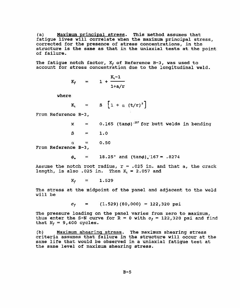
(a) Maximum nrinci~al stress. This method assumes thatfatigue lives will correlate when the maximum principal stress,corrected for the presence of stress concentrations, in thestructure is the same as that in the uniaxial tests at the pointof failure.
The fatigueaccount for
notch factor, Kf of Reference B-3, was used tostress concentration due to the longitudinal weld.
~-lKf=l+
l+a/r
where
K = B [1+ a (t/r)’]From Reference B-3,
x = 0.165 (tan@)”iG’for butt welds in bending
B = 1.0
0.50From Referenc~ B-3=,
@m = 18.25° and (tan@).”167= .8274
Assume the notch root radius, r = .025 in. and that a, the cracklength, is also .025 in. Then K~ = 2.057 and
Kt = 1.529
The stress at the midpoint of the panel and adjacent to the weldwill be
of = (1.529)(80,000) = 122,320 psi
The pressure loading on the panel varies from zero to maximum,thus enter the S-N curve for R = O with af = 122,320 psi and findthat Nf = 9,400 cycles.
(b) Maximum shearina stress. The maximum shearing stresscriteria assumes that failure in the structure will occur at thesame life that would be observed in a uniaxial fatigue test atthe same level of maximum shearing stress.
B-5

I 11 2h’
Reversals to failure (109 scale]
FigureB-3. S~rain-LifeCurvesShowingTotalElasticand PlasticStrainComponents(takenfromReferenceB-5)
B-6

For the plate and for the uniaxial test specimen,
01
r = —max
2
Applying this relationship to the R=O S-N cume gives the curvelabeled “~~~,”in Figure B-2. Using the same value of Kf found in(a) above yields
Tmax (1.529)(40,000) = 61,160 psiIn this case the s=amelife is obtained as in case (a)
Nf = 9,400 cycles
(c) Maximum octahedral shearinq stress. This criterionassumes that failure will occur at the same lives when themaximum octahedral stress in the structure is the same as that inthe uniaxial fatigue test. Octahedral shearing stress is givenby
1
r =- [
(al-a,)’ + (a2-u3)2 + (U1-U3)2 11/2
Ott
3
For the uniaxial test specimen U2 = us = O this reduces to
Applying this constant to the S-N curve yields the curve labeled!l~e=~tlin Figure B-2.
For the plate al = 80,000 psi, a2 = 36,520 psi, aa = o whichyields
T =Ott
32,710 psi
Applying the value of Kt found in (a) to rOc~,the fatigue life isNt = 18,000 cycles.
B-7
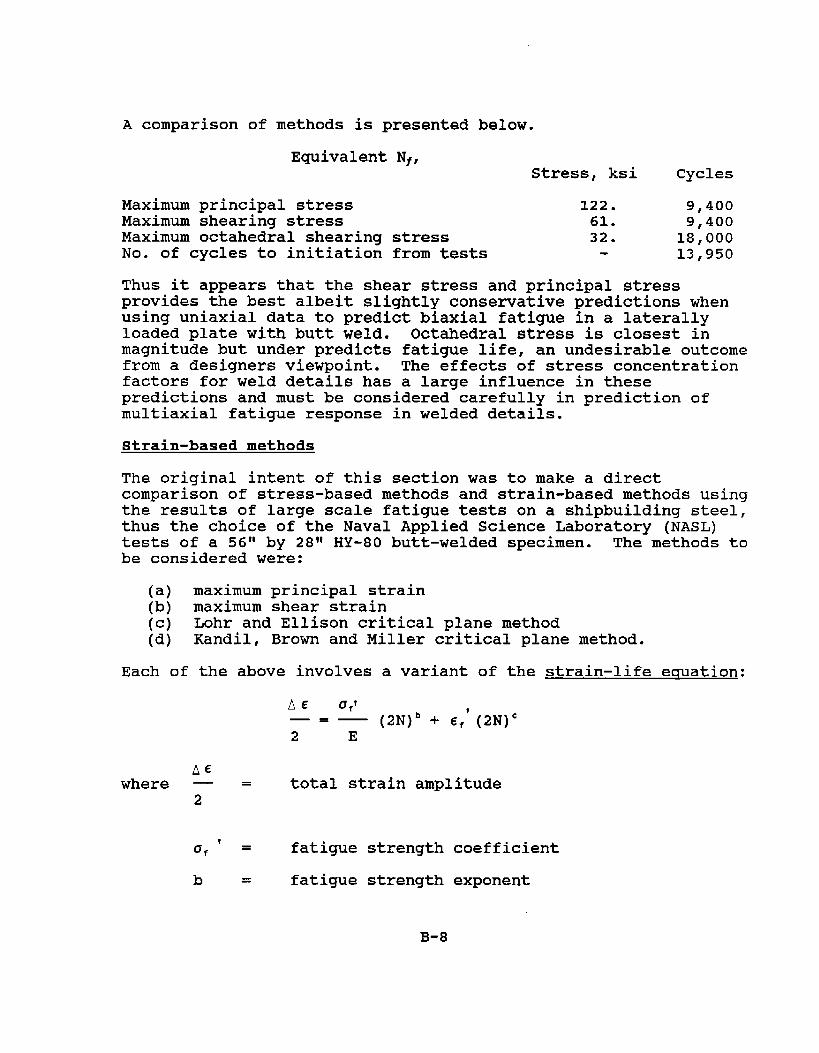
A comparison of methods is presented below.
Equivalent Nf,Stress, ksi Cycles
Maximum principal stress 122. 9,400Maximum shearing stress 61. 9,400Maximum octahedral shearing stress 32. 18,000No. of cycles to initiation from tests 13,950
Thus it appears that the shear stress and principal stressprovides the best albeit slightly consenative predictions whenusing uniaxial data to predict biaxial fatigue in a laterallyloaded plate with butt weld. Octahedral stress is closest inmagnitude but under predicts fatigue life, an undesirable outcomefrom a designers viewpoint. The effects of stress concentrationfactors for weld details has a large influence in thesepredictions and must be considered carefully in prediction ofmultiaxial fatigue response in welded details.
Strain-based methods
The original intent of this section was to make a directcomparison of stress-based methods and strain-based methods usingthe results of large scale fatigue tests on a shipbuilding steel,thus the choice of the Naval Applied Science Laboratory (NASL)tests of a 56” by 281!HY-80 butt-welded specimen. The methods tobe considered were:
(a) maximum principal strain(b) maximum shear strain(c) Lohr and Ellison critical plane method(d) Kandil, Brown and Miller critical plane method.
Each of the above involves a variant of the strain-life equation:
AE oft—=— (2N)’ + C,’(2N)C2 E
AEwhere — = total strain amplitude
2
ITf’= fatigue strength coefficient
b = fatigue strength exponent
B-8

Ef’ = fatigue ductility coefficient
c = fatigue ductility exponent
2N = number of stress reversals.
A graphical interpretation of the cyclic constraints a~; ~~, band c is shown in Figure B-3 taken from Reference B-5. The samereference contains a summary of the monotonic and cyclic strainproperties of selected engineering alloys -- a list that is aboutas complete as any available from other public domain sources.While the properties of a number of steels are included, HY-80 isnot among them, and therein lies one of the problems in applyingstrain methods -- lack of a comprehensive and complete tabulationof multiaxial fatigue properties. In the absence of reliableinformation on these properties for HY-80 it was not possible toproceed further in the comparison of stress-based with strain-based biaxial life predictions.
B-9

REFERENCES FOR APPENDIX B
B-1. Gaites, R.A. and M. Rosen, “Fatigue of Large ScaleUniformly Loaded Simply Supported Butt Welded RectangularPlatesJr, Naval Applied Science Laboratory, Brooklyn, NY,Lab Project 930-23, Progress Report 9, SF 35-422-324,Task 2025, 31 October 1968.
B-2 . Tiraoshenko, S. and S. Woinowsky-Krieger, “Theory ofPlates and Shellsff, 2nd edition, McGraw-Hill.
B-3 . Yung, J.Y. and F.V. Lawrence, “Analytical and GraphicalAids for the Fatigue Design of Weldments’1, AmericanWelding Society, Proceedings on Conference on Fitness ofPurpose for Welded Construction, May 14-16, 1985.
B-4 . Yung, J.Y. and F.V. Lawrence, “A Comparison of Methodsfor Predicting Weldrnent Fatigue Life Under Variable LoadHistories”, College of Engineering, University ofIllinois at Urbana-Champaign, Materials Engineering -Mechanical Behavior, Report No. 117/UILU-ENG85-3601,January 1985.
B-5. Fuchs, H.O. and R.I. Stepheus, I!MetalFatigue inEngineeringlf, John Wiley & Sons, 1980.
B-10

COMMITTEE ON MARINE STRUCTURES
Commission on Engineering and Technical Systems
National Academy of Sciences - National Research Council
The COMMITTEE ON MARINE STRUCTURES has technical cognizance overthe interagency Ship Structure Committee’s research program.
Stanley G. Stiansen (Chairman), Riverhead, NYMark Y. Berman, Amoco Production Company, Tulsa, OKPeter A. Gale, Webb Institute of Naval Architecture, Glen Cove, NYRolf D. Glasfeld, General Dynamics Corporation, Groton, CTWilliam H. Hartt, Florida Atlantic University, Boca Raton, FLPaul H. Wirsching, University of Arizona, Tucson, AZAlexander B. Stavovyr National Research Council, Washington, DCMichael K. Parmelee, secretary, Ship Structure Committee,
Washington, DC
LOADS WQRKGRQUP
Paul H. Wirsching (Chairman), University of Arizona, Tucson, AZSubrata K. Chakrabarti, Chicago Bridge and Iron Company, Plainfield, ILKeith D. Hjelmstad, University of Illinois, Urbana, ILHsien Yun Jan, Martech Incorporated, Neshanic Station, NJJack Y. K. Lou, Texas A & M University, College Station, TXNaresh Maniar, M. Rosenblatt & Son, Incorporated, New York, NYSolomon C. S. Yim, Oregon State University, Corvallis, OR
MATERIAL,S__WORK GROUP
William H. Hartt (Chairman), Florida Atlantic University, Boca Raton, FLFereshteh Ebrahimi, University of Florida, Gainesville, FLSantiagO Ibarra, Jr., Amoco corporation, Naperville, ILPaul A. Lagace, Massachusetts Institute of Technology, Cambridge, MAJohn Landes, University of Tennessee, Knoxville, TNMamdouh M. Salama, Conoco Incorporated, Ponca City, OKJames M. Sawhill, Jr., Newport News Shipbuilding, Newport News, VA
SHIP STRUCTURE COMMITTEE PUBLICATIONS
SSC-336 Liuuid Slosh Loadinq_,in Slack.Ship Tanks” Forces on-–-.......t..,._.—Internal Structures ~_Pressures by N. A. Hamlin 1986
SSC-337 Part 1 - ShkF~~cX.u_ze Mechanisms In.vestiqation by KarlA. Stambaugh and William A. Wood 1987
SSC-337 Part 2 - ShiD.,.rzac_tureMechanisms.. -.,A,.N.Q.n.YExpert’sGuidefor Inspecti~g. .~_nd__.Determiningthe.Causes of.._SiqnificantShiw Fractures by Karl A. Stambaugh and William A. Wood1987
SSC-338 FatiQue Prediction Analy,Sis _Vali.dat.iAon_from SL-7 HatchCorner Strain_D.~ta by Jen-Wen Chiou and Yung-Kuang Chen1985
SSC-339 lce Loads.,and..Ship .Response to Ice -.A Sec.~od_..SeasonbyC. Daley, J. W. St. John, R. Brown, J. Meyer, and 1. Glen1990
SSC-340 Ice For_c.es,..and.Ship Response to lce - .Con.E_olidat_ionReportby C. Daley, J. W. St. John, R. Brown, and 1+ Glen 1990
SSC-341 Global Ice Forces and ,S.h.ipResponse.tg Zc.e by P. Minnick,J. W. St. John, B. Cowper, and M. Edgecomb 1990
SSC-342 Global Ice Fore.eq..and Ship Response to .Ic.q,.:.Analysis ofIce Ramming__.FoX_c.esby Yung-Kuang Chen, Alfred L. T.unik,and Albert P-Y ‘Chen 1990
SSC-343 Global Ica Io.zces and Ship Response.to I.c.e--SecondSeason by P. Minnick and J. W. St. John 1990
SSC-346 Fatiwe.,.Ch_aracteri.zation of. Fabricated._Sh.i~ Details -Phase ~ by K. K. Park and F. V. Lawrence, Jr. 1988
SSC-349 Development of.,a.Generalized Onboard R@spo.~.se M~SYSt@m ~P_has.@_._I.)by F. W. DeBord, Jr. and B. Hennessy1987
SSC-350 Ship V~b,ratjQn. .Design.Guide by Edward F. Noonan 1989
SSC-351 An IntLodu_ctlon..to Structural Reliability. .T.heory byAlaa E. Mansour 1990
SSC-355 Relation .o&.Qspaction Findings to..Fat_ig.u_e__ReliabilitYbyM. Shinozuka 1989
None Ship Structure Committee Publications - A SpeXi.a~Bibliography 1983