srs side recovery system (wrecker) operations and … · 2016-11-08 · 5-376-000114 rev. 1 - 9/14...
TRANSCRIPT

5-376-000114REV. 1 - 9/14
© 20014 Jerr-Dan Corporation. All Rights Reserved.
SRSSIDE RECOVERY
SYSTEM(WRECKER)
OPERATIONS AND MAINTENANCEMANUAL
13224 Fountainhead PlazaHagerstown, MD 21742Phone (717) 597-7111
www.jerr-dan.com

5-376-000114REV. 1 - 9/14
THIS PAGE INTENTIONALLY LEFT BLANK

5-376-000114REV. 1 - 9/14
© 20014 Jerr-Dan Corporation. All Rights Reserved.
FOREWORD
This manual serves as a guide for the owner and operator in the safe opera-
tion and optimum performance of your Jerr-Dan equipment.
For your safety, and the safety of others, you must
• know the proper use of the equipment
• use the equipment within its capability
• develope consistent habits of proper use
• use good judgement
Before attempting to operate the unit, carefully read all sections of this manual.
Keep this manual with your equipment at all times. Refer to it if in doubt of
proper operation.
Information contained in this manual reflects how your Jerr-Dan equipment
was built at the factory. Modifications or additions by the distributor or
owner are not reflected in this manual.
This manual does not include operation and maintenance information for the
commercial chassis (International, Ford, GM, etc.). That information is pro-
vided by the chassis manufacturer.
When inquiring about operation, maintenance or warranty, please have ready
your equipment’s Sales Order Number, Serial Number and Model Number.
This information can be found on the aluminum tag riveted inside the Side
Recovery System tool compartment on the drivers side.

5-376-000114REV. 1 - 9/14
Jerr-Dan Corporation strives to provide information that is accurate, com-
plete and useful. All information contained in this manual is as accurate as
known at the time of publication and is subject to change, without notice, as
a result of continuous product improvements. Jerr-Dan reserves the right to
amend the information in this document at any time without prior notice.
Should you find inadequacies in the text, please send your comments to the
following address:
Jerr-Dan CorporationAttn: Technical Publications13224 Fountainhead PlazaHagerstown, MD 21742
or by e-mail at [email protected].
Always keep this manual in your vehicle so the operator can study it as
needed before a recovery. Remember to replace the manual if lost.
Additional or replacement manuals or replacement safety warning labels
can be ordered by calling Jerr-Dan Parts at 717-597-7111.
The material in this document is the property of Jerr-Dan Corporation. No
part of this document may be photocopied, reproduced or translated to an-
other language without the express written consent of Jerr-Dan Corporation.
Patents Pending.
Jerr-Dan and the Jerr-Dan logo are registered trademarks of Jerr-Dan Corpo-
ration, Hagerstown, MD USA.

5-376-000114REV. 1 - 9/14
Page i
Section I: SafetySafety (General) ....................................................................... 1Ratings: ................................................................................... 3
SRS-W25S ........................................................................ 3SRS-W35S ........................................................................ 3
Safety Points ........................................................................... 5Capacity/Rating Information Placards ...................................... 9Saftey Warning Labels ........................................................... 10Operation Placards and Labels .............................................. 11
Section II: OperationOperation ............................................................................... 13
WinchManual Remote Free-Spool - Disengaging ................. 23Manual Remote Free-Spool - Engaging ..................... 24
Section III: MaintenanceMaintenance and Lubrication ................................................. 27Fastener Torque Specifications .............................................. 28Oils and Greases ................................................................... 29Wire Rope Handling and Inspection ....................................... 30Lubrication Points .................................................................. 32Trouble Shooting .................................................................... 33Hydraulic System .................................................................. 33Hydraulic Clutch Pump .......................................................... 34P.T.O. Functioning Improperly ................................................ 35Hydraulic Pump ..................................................................... 35Winch Functioning Improperly ................................................ 36
Section IV: GlossaryGlossary ................................................................................ 37
TABLE OF CONTENTS
5-376-000114REV. 1 - 9/14
Page ii
THIS PAGE INTENTIONALLY LEFT BLANK

5-376-000114REV. 1 - 9/14
Section I: SafetyPage 1
The safe operation of your Jerr-Dan Wrecker is your responsibility. Readthis manual and the truck manufacturer’s manual and thoroughly understandthem. You can be held legally responsible for injuries or damage resultingfrom unsafe operating practices.
Our recommendations for operating your equipment can help you avoidunsafe practices and their bad consequences. These recommendationsare contained in this manual.
Jerr-Dan Corporation is not responsible for the results of any unsafe practiceof tow operators or for the failure of your equipment or its accessories resultingfrom improper use or maintenance.
The danger from a vehicle continues after it is disabled or wrecked.Recovering or towing vehicles can be dangerous too! The danger threatenstow operators and everyone else close by. As a tow operator you mustdevelop an awareness of the hazards involved. You must use every safeguardto prevent injuries.
Careful consideration of the immediate surrounding conditions such as theweather, terrain, type or condition of the vehicle to be recovered and thecondition and experience of the operator is foremost to the safety andsuccess of the operation.
Wire rope cables wear out or can become damaged. Periodically inspectthe wire rope cable for any signs of fatigue or damage. Check the hooks tobe sure they have not been bent or deformed. Replace immediately whendamaged. Refer to the Wire Rope Handling and Inspection Section.
For each step in operating your equipment develop the habit of asking yourself"is it safe to proceed?" Carefully check your set up before starting a lift ortow.
Because recoveries can be so different, we cannot warn you of all the possiblehazards you will encounter, but we will tell you of the most common hazardsthat we know about. We also strongly recommend that you receivespecialized and advanced training from a professional Towing and Recoveryinstructor before operating any recovery equipment.
SAFETY

5-376-000114REV. 1 - 9/14
Section I: SafetyPage 2
To alert personnel to hazardous operating practices, safety messages areused throughout the manual. Each safety message contains a safety alertsymbol and a signal word to identify the hazard's degree of seriousness.
CAUTION:Identifies when a potentially hazardous situation exists and mayresult in a minor or moderate injury or property damage.
WARNING:Identifies when a potentially hazardous situation exists and couldresult in death or serious injury.
DANGER:Identifies when an imminently hazardous situation exists and canresult in death or serious injury.

5-376-000114REV. 1 - 9/14
Section I: SafetyPage 3
DO NOT EXCEED THE FOLLOWING RATINGS:
SRS-W25
MAXIMUM STRUCTURAL RATING: ........................................ 35,000 lbs
WINCH RATING: (Dp Planetary Gear) 1
Each Drum (Single Speed, Variable Control) ............... 25,000 lbs
WIRE ROPE:Working Limit Each Line ............................................. 11,770 lbsNominal Breaking Strength ......................................... 41,200 lbsConstruction .......................................... 6 x 37 EIPS RRL IWRCDiameter ......................................................................... 5/8 inchStandard Length .............................................................200 Feet
SRS-W35S
MAXIMUM STRUCTURAL RATING: ........................................ 35,000 lbs
WINCH RATING: (Dp Planetary Gear) 1
Each Drum (Single Speed, Variable Control) ............... 35,000 lbs
WIRE ROPE: (Standard)Working Limit Each Line ............................................. 11,770 lbsNominal Breaking Strength ......................................... 41,200 lbsConstruction .......................................... 6 x 37 EIPS RRL IWRCDiameter ......................................................................... 5/8 inchStandard Length .............................................................250 Feet
WIRE ROPE: (Optional)Working Limit Each Line ............................................. 16,800 lbsNominal Breaking Strength ......................................... 58,800 lbsConstruction .......................................... 6 x 37 EIPS RRL IWRCDiameter ......................................................................... 3/4 inchStandard Length .............................................................200 Feet
1 SAE J706: Surface Vehicle Recommended Practices - Rating of Winches

5-376-000114REV. 1 - 9/14
Section I: SafetyPage 4
NOTE
These ratings apply to the structural design of the Side Recovery System only.They might be limited by the axle rating and gross vehicle weight rating of thetruck chassis.
The payload and towing capacity of any towing vehicle must meet thefollowing: • The actual payload on the towing vehicle must not exceed the posted
rating and the towed vehicle load must not exceed the posted lift /towing ratings.
• The total weight of the towing vehicle (cab chassis, body, payload, driver, passenger(s), tools, fuel, etc.) and the towed vehicle load must not
exceed the GVWR (Gross Vehicle Weight Rating) of the towing vehicle.
• The total weight of the towing vehicle and a towed vehicle load must bedistributed so that each axle’s GAWR (Gross Axle Weight Rating) is notexceeded.
• The total weight of the towing vehicle and towed vehicle (everythingthat moves with the towing vehicle) must not exceed the GCWR(Gross Combination Weight Rating) of the towing vehicle.
Staying within these ratings is necessary to maintain the safety andperformance of the towing vehicle.
CHECK TRUCK MANUAL FOR SPECIFIC GVW & AXLE RATINGS. ALSO LOOKAT THE CERTIFICATION DECAL AFFIXED TO DRIVER’S SIDE DOOR JAMB, HINGEPILLAR OR LATCH POST AND THE STRUCTURAL CAPACITIES PLACARD INSIDETHE SIDE RECOVERY SYSTEM TOOL COMPARTMENT ON THE DRIVERS SIDE.
5-376-000114REV. 1 - 9/14
Section I: SafetyPage 5
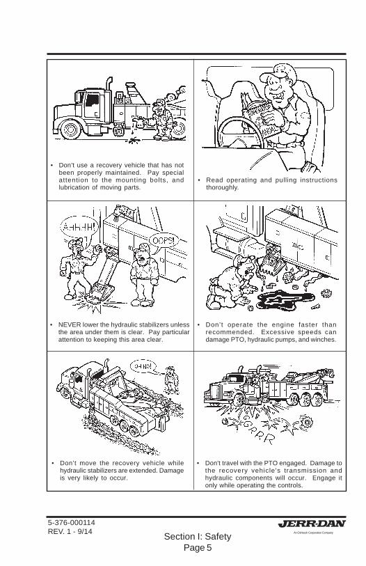
• Don’t use a recovery vehicle that has notbeen properly maintained. Pay specialattention to the mounting bolts, andlubrication of moving parts.
• Read operating and pulling instructionsthoroughly.
• Don’t operate the engine faster thanrecommended. Excessive speeds candamage PTO, hydraulic pumps, and winches.
• Don't travel with the PTO engaged. Damage tothe recovery vehicle's transmission andhydraulic components will occur. Engage itonly while operating the controls.
• NEVER lower the hydraulic stabilizers unlessthe area under them is clear. Pay particularattention to keeping this area clear.
• Don’t move the recovery vehicle whilehydraulic stabilizers are extended. Damageis very likely to occur.

5-376-000114REV. 1 - 9/14
Section I: SafetyPage 6
• Make sure you are clear of oncoming traffic.Dual controls (driver side and passenger side)are standard on your Jerr-Dan Side RecoverySystem.
• Know the loads being moved. DO NOTOVERLOAD! NEVER exceed the ratedcapacity of the body or truck chassis and it'scomponents.
• NEVER permit bystanders in the area whileperforming a pull. Keep them clear of thedanger zone.
• Observe all CAUTION, WARNING, andDANGER decals.
• Stay clear of equipment to avoid pinchinginjury.
• Always lower the stabilizers before pulling aload to stabilize the truck.

5-376-000114REV. 1 - 9/14
Section I: SafetyPage 7
• Make sure all brakes and locks are properlyset on the recovery vehicle.
• Don't exceed the ratings. Stay withinnameplate ratings.
• Maintain winch cable/wire rope in goodcondition. Replace when worn, kinked orfrayed. Do not use cable clamps.
• Vehicle must be located on a firm surfacethat will provide support for the stabilizerloading. Use caution when setting up nearoverhanging banks or excavations.
• NEVER make a pull or movement whileanyone is close to the vehicle to be moved.
• KEEP ALERT! Do not be distracted duringany operating sequences.

5-376-000114REV. 1 - 9/14
Section I: SafetyPage 8
• NEVER allow riders in the vehicle during pulling.

5-376-000114REV. 1 - 9/14
Section I: SafetyPage 9
CAPACITY/RATING INFORMATION PLACARDS
These placards provide information about Side Recovery System ratings,capacities and load limits. You must stay within these ratings/capacitieswhen using the Jerr-Dan Side Recovery System. These placards must notbe obliterated, removed or painted over. They are there to remind and protectthe operator. (Not all placards are used on all units) If a placard becomeslost or unreadable, it should be replaced. Replacements are available throughthe Service Parts Department.

5-376-000114REV. 1 - 9/14
Section I: SafetyPage 10
SAFETY WARNING LABELS
These safety warning labels describe hazards and what happens if youencounter them. Read each safety warning lable and figure out how to avoidthe hazard. These lables must not be obliterated, removed or painted over.They are there to remind and protect the operator. (Not all decals are usedon all units) If a decal becomes lost or unreadable, it should be replaced.Replacements are available through the Service Parts Department.
WARNINGWARNING
580580
STAND CLEAR OF
OUTRIGGER/STABILIZERS
TO AVOID CRUSHING INJURY
WARNING
037
MOVING PARTS
KEEP HANDS AND FEET CLEAR
OF THIS AREA
262
WARNINGA MINIMUM OF 5 WRAPS OF CABLE MUST BE LEFT
ON THE DRUM TO ACHIEVE RATED LOAD.
NOT TO BE USED IN THE MOVING OR LIFTING OF PERSONS.

5-376-000114REV. 1 - 9/14
Section I: SafetyPage 11
OPERATION PLACARDS AND LABELS

5-376-000114REV. 1 - 9/14
Section I: SafetyPage 12

5-376-000114REV. 1 - 9/14
Section II: OperationPage 13
OPERATION
OPERATION
The safe operation of your Jerr-Dan wrecker is your responsibility. You canbe held legally responsible for any injuries or damage caused by the unsafeoperation of your equipment. If you follow our tested and proven procedureyou will operate the equipment properly. Remember you alone are alwaysresponsible for your actions.
Always know the weight distribution of your load and ensure you are withinyour truck’s Gross Axle Weight Rating (GAWR), Gross Vehicle Weight Rating(GVWR) and Gross Combination Weight Rating (GCWR) as well as anyfederal or state roading regulation. In addition, be aware of your truck's overallloaded height to be sure that you are under the federal bridge law height of13 feet 6 inches.
The operating controls for your wrecker are conveniently located on both thedriver and passenger sides of the deck to keep you safe and out of harmsway. Always operate the controls from the side away from traffic.Also, all of the hydraulic functions of the SRS are conveniently operated bya hand held wireless remote controller .
The following wired remote controlsare provided:
1. Winch Controls
2. Stabilizer Up Controls
3. Stabilizer Down Controls
4. Boom Controls
JERR- DAN
BOOMLH
RH
IN
OUT
WINCH
RH S P ADEUP UP
DN DN
LH S P ADE

5-376-000114REV. 1 - 9/14
Section II: OperationPage 14
The following wireless remotecontrols are provided:
1. Power (Green) - ON
2. Power (Red) - OFF
3. Indicator Light
4. Winch Controls
5. Stabilizer Up Controls
6. Stabilizer Down Controls
7. Boom Controls
Follow these simple steps tooperate the controller:
1. With the trucks engine runningand the PTO engaged, press thegreen button on the handcontroller to turn the power on tothe hand controller. The red lighton the controller will illuminateand flash.
2. Depress the appropriate yellowbutton on the hand controller forthe desired function(s). The redlight will stop flashing whenevera function is being operated.

5-376-000114REV. 1 - 9/14
Section II: OperationPage 15
3. To turn off the power to the handcontroller, simply press the redbutton. The red light will stopilluminating.
In the event of a hand controller malfunction, the SRS hydraulic functionscan be operated using the valve manual override buttons. Refer to thedecal located in the passenger side tool compartment on the access coverto the control valve.

5-376-000114REV. 1 - 9/14
Section II: OperationPage 16
Follow these simple steps:
1. Turn on the safety and worklights. (Switches are located onthe switch panel in the dash.)
2. Position the recovery vehicle onfirm ground as close as possibleto the vehicle you intend to pull.
3. Place the recovery vehicle’stransmission gear selector intoNeutral or Park and set theparking brakes.
4. Engage the power take-off(PTO). Refer to PTO operator’smanual. NEVER TRAVEL WITHTHE POWER TAKE-OFFCONTROL ENGAGED. Thiscould result in damage to thePTO unit and the recoveryvehicle’s transmission.
HL73
HL51
LOR
HI
LO 26 H
L
HL84
5-376-000114REV. 1 - 9/14
Section II: OperationPage 17
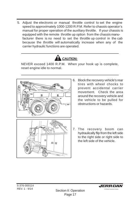
5. Adjust the electronic or manual throttle control to set the enginespeed to approximately 1000-1200 R.P.M. Refer to chassis operator’smanual for proper operation of the auxiliary throttle. If your chassis isequipped with the remote throttle up option from the chassis manu-facturer there is no need to set the throttle up control in the cabbecause the throttle will automatically increase when any of thecarrier hydraulic functions are operated.
CAUTION:
NEVER exceed 1400 R.P.M. When your hook up is complete,reset engine idle to normal.
6. Block the recovery vehicle's reartires with wheel chocks toprevent accidental carriermovement. Check the areaaround the recovery vehicle andthe vehicle to be pulled forobstructions or hazards.
7. The recovery boom canhydraulically flip from the left sideto the right side or right side tothe left side of the vehicle.

5-376-000114REV. 1 - 9/14
Section II: OperationPage 18
8. Using the hand controller, flip therecovery boom to the side of therecovery vehicle that isnecessary to make the recovery.
9. Next, lower the stabilizers to theground.
10. The left and right stabilizersoperate independently of eachother. The stabilizers only needto touch the ground to supportthe load. Do not attempt to usethe stabilizers to level or raisethe truck.
CAUTION:
Stand clear of the outrigger/stabilizers to avoid crushing injury. Areashould be clear of feet when lowering the stabilizers. Also, nevermove the recovery vehicle with the stabilizers on the ground ordamage to the stabilizers can occur.
11. If you are on gravel or a softsurface the integral spades cangive you more gripping power.

5-376-000114REV. 1 - 9/14
Section II: OperationPage 19
CAUTION:
Do not use spades on pavement or concrete. Damage to thepavement or concrete may occur.
12. If you are on concrete orpavement and can't use theintegral spades, pull the spaderetaining pin allowing thestabilizer pad to level out flatbefore completely lowering thestabilizers.
NOTE:Jerr-Dan also recommends thatthe rear stabilizers are loweredto help stabilize the recoveryvehicle. (See Heavy DutyWrecker Operation Manual)
13. Next, remove the wire rope/cablefrom the tie back and unreelenough of the wire rope/cablefrom the winch to make yourhookup. This can be done usingthe winch control on the handcontroller and unreeling the wirerope/cable from the winch whilekeeping the wire rope/cable taut.You can also use the remotewinch free spool device. Thisallows for rapid unspooling of thewire rope/cable from the winch.(See winch operation)

5-376-000114REV. 1 - 9/14
Section II: OperationPage 20
WARNING:
Maintain a minimum of five (5) wraps of wire rope/cable on thewinch drum at all times. Also maintain a uniform wrap of wire rope/cable on the drum.
14. Attach the hook to the cable andsecure with the screw pin andshackle.
15. Attach the wire rope/cable to thevehicle to be pulled. Always useV-straps or hook-up chains toattach the wire rope/cable to thevehicle. Refer to the AAA orvehicle manufacturer'stowing manual for correctattachment points. A snatchblock may be used if required topull from a lower angle.
CAUTION:
Always use V-straps or hook-up chains. Never connect the wirerope/cable hook directly to vehicle. Never hook the wire rope/cableback onto itself because damage to the wire rope/cable will occur.

5-376-000114REV. 1 - 9/14
Section II: OperationPage 21
CAUTION:
Always attach the wire rope/cable with the hook pointing up.
NOTE:If the vehicle is parked on anincline, leave the parking brakepartially engaged to prevent itfrom rolling forward on its own.
16. Using the winch control on thehand controller, begin winchingthe load.
17. Continue winching until the loadis recovered and in a positionwhere it can be disconnectedfrom the winch wire rope/cable.
CAUTION:
Remain clear of the load while winching. Never walk between thewinch and its load when the winch and wire rope/cable is undertension.

5-376-000114REV. 1 - 9/14
Section II: OperationPage 22
18. Secure the recovered vehicle toprevent it from rolling. If thevehicle has wheels, place wheelchocks against the tires.
19. Using the remote controllerunwind some of the wire rope/cable to relieve the tension onthe wire rope.
20. Unhook the wire rope/cable fromthe recovered vehicle.
21. Remove the hook from the wirerope/cable and store in toolcompartment.

5-376-000114REV. 1 - 9/14
Section II: OperationPage 23
22. Reel in any extra wire rope/cableand secure end of wire rope/cable to tie back.
23. Retract the stabilizers.
CAUTION:If you removed the stabilizer footpin earlier to use the stabilizerfoot flat, the stabilizer foot willself stow it's self when thestabilizers are retracted.
24. Remove the wheel chocks fromthe recovery vehicle's rear tires.
25. Disconnect the power take-off(PTO). Refer to PTO operator’smanual. NEVER TRAVEL WITHTHE POWER TAKE-OFFCONTROL ENGAGED. Thiscould result in damage to thePTO unit and the recoveryvehicle’s transmission.

5-376-000114REV. 1 - 9/14
Section II: OperationPage 24
WINCH OPERATION - AIR REMOTE FREE-SPOOL
Follow these simple steps todisengage the winch:
1. To disengage the winch “free-spool”, toggle the Free Spoolswitch to the "free-spool"position. The red light willilluminate. Never pull the freespool knob while the wirerope/cable is under load.
2. The winch clutch is now releasedand the wire rope/cable may bepulled off by hand.
WARNING:Maintain a minimum of five (5)wraps of wire rope/cable on thewinch drum at all times. Alsomaintain a uniform wrap of wirerope/cable on the drum.
WARNING:Always wear gloves whenhandling wire rope/cable.

5-376-000114REV. 1 - 9/14
Section II: OperationPage 25
Follow these simple steps to re-engage the winch:
1. To re-engage the winch clutch,toggle the Free Spool switch tothe engaged position. The redlight will stop illuminating. Runthe winch in reverse until thewinch drum starts turning.
2. After the winch clutch is fullyengaged, the winch is ready forwinching.
CAUTION:Do not attempt to pull a loadunless the winch free spool iscompletely engaged.
CAUTION:
Jerr-Dan does not recommend that the winch air tensioner pressurebe adjusted. If you do adjust the air tensioner pressure to assist in"free-spooling" the wire rope/cable from the winch drum, make sureto adjust the pressure back to the factory setting of 40-50 PSI after"free-spooling". Birdnesting of the wire rope/cable may occur andcause damage to the wire rope/cable and or the winch.

5-376-000114REV. 1 - 9/14
Section II: OperationPage 26
THIS PAGE INTENTIONALLY LEFT BLANK
Section III: MaintenancePage 27
5-376-000114REV. 1 - 9/14
MAINTENANCE AND LUBRICATION
Your Jerr-Dan equipment has been designed to give you excellent serviceand long life, but like all equipment, it requires proper and periodicmaintenance. The truck chassis itself is on a maintenance schedulerecommended by the manufacturer. Follow these guidelines and protectyour vehicle warranty. There are a number of different lubricants used onyour Jerr-Dan equipment. The following Lubricant Chart shows the properlubricant and the most common brands and specification which meet therequirements.
Use only safe practices when maintaining this equipment. Always shut offthe engine before reaching into pinch areas.
Inspect your equipment periodically for damage or evidence of pending failure.Damaged or broken parts should be replaced immediately. Never operatethe carrier or any of its components if they are defective or operatingimproperly. The cause of any binding or leakage should be determinedimmediately and the problem promptly fixed.
Most of the pivot joints utilize high strength composite bearings withhardened and plated pins to drastically reduce maintenance, down-timeand the cost of lubrication over the life of the product. There are however afew areas that still require some lubrication or maintenance. The LubricationChart and diagram shows the location of these points, lubrication schedules,and what type of lubricant to use.
If a cylinder seal leaks, disassemble the cylinder and find the cause of theleak. Small scores caused by chips or contaminated fluid can usually beworked out with fine emery cloth to avoid repetition of the trouble. Wheneverany seal replacement is necessary, it is always advisable to replace allseals in that component. These seals are available in kits. Also, thoroughlyclean all components before reassembly.
The Side Recovery System is mounted to the truck chassis by bolts. Werecommend that these bolts be inspected within the first 30 days andinspected and retorqed every 90 days thereafter. Replace any broken ordamaged bolts immediately. Refer to chart on the following page.
MAINTENANCE

Section III: MaintenancePage 28
5-376-000114REV. 1 - 9/14
• All torque values shown are for bolts (cap screws) and nuts that are either zinc-
plated or lubricated.
• Torques shown above apply only to screws and nuts used for assembly and
installation of all components, not to the chassis.
• Different torque values may be given in instructions for certain components due to
short thread engagement or low-strength internal threads.
• When nuts are used, tighten nuts to torques shown (screws or bolts should be
held but not turned). Always use a calibrated torque wrench.
• Retighten nuts of all mounting screws that secure the carrier and carrier-body
within 30 days after putting the vehicle into service. Thereafter, inspect and
retorque such screws and nuts every 90 days and after each job that imposes
extremely heavy loads on the equipment.
• Convert ft/lbs to Nm (Newton metres) by using the following formula:
Multiply: by: to get:
ft/lbs x 1.3558 = Nm (Newton metres)
FASTENER TORQUE SPECIFICATIONS
Section III: MaintenancePage 29
5-376-000114REV. 1 - 9/14
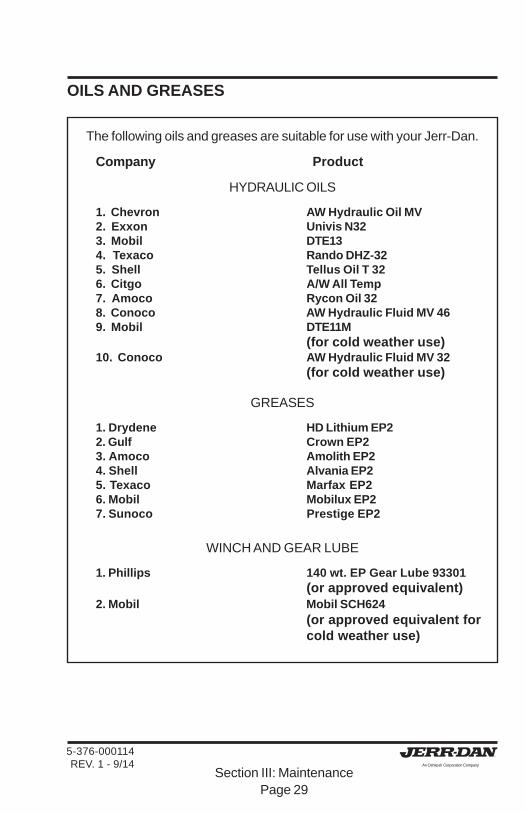
OILS AND GREASES
The following oils and greases are suitable for use with your Jerr-Dan.
Company Product
HYDRAULIC OILS
1. Chevron AW Hydraulic Oil MV2. Exxon Univis N323. Mobil DTE134. Texaco Rando DHZ-325. Shell Tellus Oil T 326. Citgo A/W All Temp7. Amoco Rycon Oil 328. Conoco AW Hydraulic Fluid MV 469. Mobil DTE11M
(for cold weather use)10. Conoco AW Hydraulic Fluid MV 32
(for cold weather use)
GREASES
1. Drydene HD Lithium EP22. Gulf Crown EP23. Amoco Amolith EP24. Shell Alvania EP25. Texaco Marfax EP26. Mobil Mobilux EP27. Sunoco Prestige EP2
WINCH AND GEAR LUBE
1. Phillips 140 wt. EP Gear Lube 93301(or approved equivalent)
2. Mobil Mobil SCH624(or approved equivalent forcold weather use)

Section III: MaintenancePage 30
5-376-000114REV. 1 - 9/14
WIRE ROPE HANDLING AND INSPECTION
A new wire rope requires a break-in period. Run the wire rope throughseveral cycles at low speeds gradually increasing the load on the wire rope.Make sure that the wraps of the wire rope are tight and evenly wound on thewinch drum. A loose wire rope on the winch drum will cause crushing of thewire rope when heavy loads are applied.
All wire rope in continuous service should be observed during normal operationand visually inspected on a weekly basis. A complete and thoroughinspection of all ropes in use must be made at least once a month and allrope which has been idle for a period of a month or more should be given athorough inspection before it is put back into service. All inspections shouldbe the responsibility of and performed by an appointed competent personwith the training and experience to look for deterioration of the wire rope.
WARNINGWARNINGWARNINGWARNINGWARNINGWire Rope WILL FAIL if worn-out, overloaded, damaged, improperlymaintained or abused.
Wire rope failure may cause serious injury or death!
Protect yourself and other:• ALWAYS INSPECT wire rope for WEAR, DAMAGE or ABUSE BEFORE USE.
• NEVER USE wire rope that is WORN-OUT, DAMAGED or ABUSED.
• NEVER OVERLOAD a wire rope.
• INFORM YOURSELF: Read and understand manufacturer’s literature or “Wire Rope and Sling Safety Bulletin”
REFER TO APPLICABLE CODES, STANDARDS andREGULATIONS for INSPECTION REQUIREMENTS andREMOVAL CRITERIA.
Section III: MaintenancePage 31
5-376-000114REV. 1 - 9/14
It is good practice , where the equipment is consistently in use, to give therope a certain length of service, several hundred hours, several weeks ormonths and then renew the rope regardless of it's condition. This methodeliminates the risk of fatigue causing rope failure.
Any deterioration, resulting in a suspected loss of original rope strength,should be carefully examined and a determination made as to whether furtheruse of the wire rope would constitute a safety hazard.
There are certain points along any given rope which should be given moreattention than others, since some areas will be subjected to greater stresses,forces, and hazards. Some of these areas include at the winch drum, at theboom sheaves and at the end attachments.
All products are subject to age, wear and deterioration, all of which cause areduction in the products breaking strength capacity.
Probably the most common sign of rope deterioration and approaching failureis broken wires. Inspection criteria are specific as to the number of brokenwires allowable under various circumstances. It is important that a diligentsearch be made for broken wires, particularly in critical areas. Inspection ofwire rope ends should include hooks and thimbles.
Replace any wire ropes that have been abraded, crushed, kinked or twisted.
Wire rope should be routinely cleaned monthly of any and all debris. Gritand gravel can quickly reduce a wire ropes life. A wire rope should be welllubricated so that it can act and perform as it was designed. Lubricationkeeps a wire rope flexible and free from rust.
Consult the manufacturer or your local distributor for the proper replacementwire rope.

Section III: MaintenancePage 32
5-376-000114REV. 1 - 9/14
LUBRICATION POINTS
The following lubrication chart is located on the inside of the drivers sidetool compartment door.

Section III: MaintenancePage 33
5-376-000114REV. 1 - 9/14
TROUBLESHOOTING
You probably won’t require anything but preventive maintenance to keepyour equipment running, however, the following chart should help you isolateand correct minor problems if they occur with use. Any service work onthe hydraulic system should be performed by qualified mechanics. For amore comprehensive troubleshooting guide refer to Jerr-Dan’s “HydraulicTroubleshooting Guide”, part number 5-377-000013, which is availablethrough the Service Parts Department.
HYDRAULIC SYSTEMProblem Cause Solution
Slow operation a. Low engine RPM a. Speed up engineb. Low oil level b. Check dipstick and fill with
the specified oilc. Blocked or restricted c. Inspect: remove blockage
hosesd. Dirty hydraulic oil d. Drain, flush and refill with
clean oil, replace filtere. Hydraulic pump worn e. Rebuild or replace
f. Clutch Pump belt slipping f. Tighten or Replace belt
Valve Solenoid(s) a. Broken centering spring a. Inspect, clean or replacesticking or frozen or clogged with foreign
materialb. Low Amperage/Voltage b. Check Amperage/Voltage
at Solenoid
Valve leaks a. Defective seals a. Replace
Cylinder leaks a. Defective seals or rods a. Inspect and replaceb. Dirty or Defective b. Clean or Replace
CounterBalance Valve CounterBalance Valve
Erratic cylinder a. Air in the system a. Cycle hydraulic system 10function to 15 times to remove air
b. Defective pump b. Replace if necessary(pulsating)
Remote hand a. Electric power turned off a. Turn on controllercontroller fails to power on controllerrespond b. Bad or discharged battery b. Replace battery
c. Faulty Remote Hand c. Use Manual overrideControls
d. Loss of program memory d. Reprogram memory
Section III: MaintenancePage 34
5-376-000114REV. 1 - 9/14
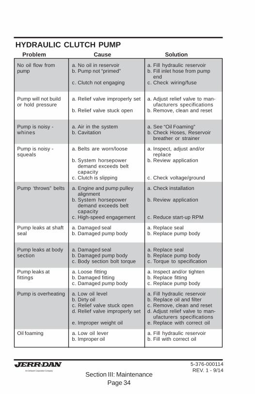
HYDRAULIC CLUTCH PUMPProblem Cause Solution
No oil flow from a. No oil in reservoir a. Fill hydraulic reservoirpump b. Pump not “primed” b. Fill inlet hose from pump
endc. Clutch not engaging c. Check wiring/fuse
Pump will not build a. Relief valve improperly set a. Adjust relief valve to man-or hold pressure ufacturers specifications
b. Relief valve stuck open b. Remove, clean and reset
Pump is noisy - a. Air in the system a. See “Oil Foaming”whines b. Cavitation b. Check Hoses, Reservoir
breather or strainer
Pump is noisy - a. Belts are worn/loose a. Inspect, adjust and/orsqueals replace
b. System horsepower b. Review applicationdemand exceeds beltcapacity
c. Clutch is slipping c. Check voltage/ground
Pump ‘throws” belts a. Engine and pump pulley a. Check installationalignment
b. System horsepower b. Review applicationdemand exceeds beltcapacity
c. High-speed engagement c. Reduce start-up RPM
Pump leaks at shaft a. Damaged seal a. Replace sealseal b. Damaged pump body b. Replace pump body
Pump leaks at body a. Damaged seal a. Replace sealsection b. Damaged pump body b. Replace pump body
c. Body section bolt torque c. Torque to specification
Pump leaks at a. Loose fitting a. Inspect and/or tightenfittings b. Damaged fitting b. Replace fitting
c. Damaged pump body c. Replace pump body
Pump is overheating a. Low oil level a. Fill hydraulic reservoirb. Dirty oil b. Replace oil and filterc. Relief valve stuck open c. Remove, clean and resetd. Relief valve improperly set d. Adjust relief valve to man-
ufacturers specificationse. Improper weight oil e. Replace with correct oil
Oil foaming a. Low oil lever a. Fill hydraulic reservoirb. Improper oil b. Fill with correct oil

Section III: MaintenancePage 35
5-376-000114REV. 1 - 9/14
P.T.O. FUNCTIONING IMPROPERLY Problem Cause Solution
Cable tight or frozen a. Cable kinked or bent a. Straighten or replaceb. Cable and P.T.O. connec- b. Inspect and adjust
tion not adjusted properlyc. Mounting bracket nuts c. Loosen if necessary
are over tightened at P.T.O.
Rattling noise in a. P.T.O. backlash too loose a. Shims must be removedP.T.O. (Consult P.T.O. Manual)
Howling Noise in a. P.T.O. backlash too tight a. Shims must be addedP.T.O. (Consult P.T.O. Manual)
Gear oil leak between a. Defective shaft seal a. Remove and replaceP.T.O. and pump
P.T.O. will not engage a. Cable and P.T.O. connec- a. Inspect and adjustor disengage tion not adjusted properly
b. Defective shifter cover b. Inspect and replaceplate
HYDRAULIC PUMPProblem Cause Solution
Pump noisy a. Low oil supply a. Fill to proper level(Cavitation) b. Heavy oil b. Fill with proper oil
(See chart)c. Dirty oil filter c. Replace filterd. Restriction in suction line d. Clean out and removee. Pump worn e. Repair or replace
Pump/Clutch Pump a. Low oil supply a. Fill to proper levelslow or fails to b. Worn or Loose Belt(s) b. Tighten or Replace Belt(s)respond
Oil heating up a. Foreign material lodged in a. Inspect and remove/relief valve replace filter
b. Using too light oil b. Drain and refill with cleanoil
c. Dirty oil c. Drain, flush and refill withclean oil/replace filter
d. Oil level too low d. Fill to proper levele. Pump worn (slippage) e. Repair or replace

Section III: MaintenancePage 36
5-376-000114REV. 1 - 9/14
HYDRAULIC PUMP - con’tProblem Cause Solution
Oil foaming a. Air leaking into suction line a. Tighten all connectionsb. Wrong kind of oil b. Drain and refill with
non-foaming type ofhydraulic oil (Seelube chart)Replace filter
c. Oil level too low c. Refill to proper level
Hydraulic oil leak a. Defective shaft seal a. Replace shaft sealbetween P.T.O. andpump
Clutch Pump leaks at a. Defective Shaft Seals a. Replace seals or PumpPulley Shaft b. Hydraulic Supply/Return b. Check hydraulic line
lines connected incorrectly connections
Pump leaks at front a. Defective seals a. Replace sealsand rear covers
WINCH FUNCTIONING IMPROPERLYProblem Cause Solution
Winch screeches a. Insufficient lubrication a. Lubricate per lube chartduring operation
Winch will not pull a. Free spooling device not a. Engageload or take in cable engaged
b. Sheared keys or broken b. Inspect or replacecoupling
c. Hydraulic pump worn c. Inspect and replaced. Insufficient pump d. Check hydraulic pump
pressure and hydraulic fluid levele. Overload e. Install snatch block in the
rigging line

5-376-000114REV. 1 - 9/14
Section IV: GlossaryPage 37
A
Anchoring Device - Used to attach cable ends, snatch blocks, safety chains,and tie-down assemblies to the towing vehicle.
Approach Angle - Angle between the plane of the platform and the ground.
Attachment - Any device that can be added to a basic unit or assembly.
Auxiliary Braking Device - A device which attaches to the disabled vehicle toassist the tow truck's brakes in retarding or stopping both vehicles.
Auxiliary Equipment - Equipment that is not necessary to perform the basicfunction of the primary equipment.
Auxiliary Towing Lights - Stop, tail, and turn signal lights attached to the trailingend of the towed vehicle and operated as part of the towing vehicle lightingsystem.
B
Bending Moment - The force times the distance from a reference point to thepoint the force is applied causing bending.
Bird Nesting - The tangling and intertwining of wraps and layers on a drum.
Body - The structure mounted on a chassis cab or that portion of the vehicle thatcarries the load.
Body Hinge - The attachment mechanism connecting the body to the hinge pinat the pivot axis about which the body rotates into the tilt position.
Body Subframe - Another term for body understructure or mounting frame.
Body Weight - Unmounted weight of a body with applicable options.
Boom - The structure member that supports the load.
Boom Angle - The boom angle is measured between a horizontal line and a linethrough the boom pivot and center of sheave.
Boom Head - The structural member at one end of the boom which can swiveland support the load lifted through the sheave and sheave support device.
GLOSSARY OF TERMS

5-376-000114REV. 1 - 9/14
Section IV: GlossaryPage 38
Boom Length - The straight line distance from center of the revolving base to thecenter of the boom head.
Brakes - Parking - A system used to hold a stopped machine in a stationaryposition.
Brakes - Service - A primary brake system used for retarding and stopping thetruck.
Bumper - DOT - A bumper designed to provide rear-end protection that meetsthe requirements of FMCSR 393.86.
Bus Bar Grid - A device used for towing vehicles by lifting one end of the towedvehicle by the wheels.
C
CA (Cab to Axle) - The distance from the back of the truck cab to the center of therear axle.
CG (Center of Gravity) - The point at which the weight of the chassis, body/equipment and payload, if collectively or individually supported, wouldbalance vertically, horizontally, and laterally.
CT (Cab to Tandem) - The distance from the back of the truck cab to a pointmidway between the tandem axles.
Cable - Steel wire rope used for pulling.
Car Carrier - Vehicles equipped to transport other vehicles mounted on a flatplatform and/or with an additional assembly attached to the rear to facilitatetowing a second vehicle. These units are also known as slidebacks,rollbacks, transporting equipment carriers and flatbeds. See Carrier.
Carrier - A platform body with a winch for loading.
Casualty Vehicle - The damaged or disabled vehicle.
Capacity - The load that a machine can lift at any given point.
CAUTION - A signal word used when a potentially hazardous situation exists thatmight result in minor injury or property damage.
5-376-000114REV. 1 - 9/14
Section IV: GlossaryPage 39
Certification Label - Required by Public Law 89-563, which states that a motorvehicle or item of motor vehicle equipment complies with all applicableFederal Motor Vehicle Safety Standards (FMVSS) in effect on the date ofmanufacture.
Chain Assemblies - Chain with all hardware and coupling devices.
Chassis Cab - A vehicle consisting of a chassis upon which is mounted a cab;capable of being driven by the addition of wheel or other items of runninggear, but lacking a body or load-carrying structure.
Completed Vehicle - A vehicle that requires no further manufacturing operationsto perform its intended function, other than minor finishing operations suchas painting.
Component - Any part of an assembly on a machine when referred to individually.
Control - A device used to control the functions of a unit.
Control Lever- A device for imparting motion into a control linkage.
Crossbar - A transverse horizontally pivoting member attached to the boom of awheel-lift or underlift for attaching towing accessories.
Curb Side - The right or passenger side of the vehicle when viewed from therear, opposite side from ROADSIDE.
Curb Weight - The weight of a vehicle in operational status, with all standardand commonly installed equipment and the fuel tank(s) filled to capacity.
Cylinder - A device which converts fluid power into a linear mechanical force andmotion usually consisting of a movable piston and piston rod within a cylinderbore.
D
DANGER - A signal word used when an imminently hazardous situation existsthat can result in death or serious injury.
Disabled Vehicle - Any vehicle that cannot operate under its own power.
Dolly - A four-wheeled carriage used in towing to support the trailing end of thetowed vehicle.

5-376-000114REV. 1 - 9/14
Section IV: GlossaryPage 40
DOT (Department of Transportation) - A federal agency dealing with regulationsconcerning both the manufacture and operation of motor vehicles and motorvehicle equipment. See NHTSA.
Driveline - The driveshaft and associated joints.
Drum - Any spool on which are wrapped ropes used in machine operation.
E
Extend Cylinder - Cylinders used to extend or retract boom structures.
F
Filter- A device whose primary function is the retention by a porous media ofinsoluble contaminants from a fluid.
Final Stage Manufacturer - A person, firm, or corporation who performs suchmanufacturing operations on an incomplete vehicle that it becomes acompleted (end-user) vehicle.
FMVSS (Federal Motor Vehicle Safety Standards) - Regulations promulgatedby NHTSA under Public Law 89-563, which are mandatory and must becomplied with when motor vehicles or items of motor vehicle equipment aremanufactured and certified thereto.
Frame - Structure on which either the upper or lower equipment is located.
Frame Cutoff - Centerline of rear axle(s) to the rearmost point of the chassisframe as modified for body installation.
Frame Lift - See Underlift.
Frame Section Modulus - The engineering term that indicates the relativestrength of frames as it relates to shape. It takes into account frame depth,flange width, and material thickness. All other things being equal, the framewith the largest section modulus will have the greatest strength and stiffness,i.e., the ability to more effectively resist deflection under load.
Free Spool - The operation of unspooling wire rope from a drum by pulling onthe end of the wire rope while the winch is stationary. The drum isdisconnected (declutched) from its powertrain during this operation.

5-376-000114REV. 1 - 9/14
Section IV: GlossaryPage 41
Forks - A device attached to the lift bar for lifting a vehicle by the tires, axle, frame,or structural member. May be classified as chain, axle, or frame forks.
FW (Frame Width) - The overall width of the chassis frame measured outside tooutside behind the cab.
G
GAWR (Gross Axle Weight Rating) - The value specified by the manufacturer asthe load-carrying capacity of a single-axle system as measured at thetire-roadway interface.
GCWR (Gross Combination Weight Rating) - Represents the entire weight of avehicle on the ground with a trailer or trailers including vehicle, equipment,driver, fuel, and payload (everything that moves with the vehicle.) Grosscombination weights published represent maximum allowed.
Grab Hook - For use with chains and some tow-sling hookups.
Grid - A device that attaches to the lift bar for engaging the tires of a towed vehicle.
GVWR (Gross Vehicle Weight Rating) - The maximum total vehicle rated capacity,measured at the tire ground interface, as rated by the chassis manufacturer.
GVW (Gross Vehicle Weight) - Value specified by the manufacturer as themaximum loaded weight of a single vehicle including all equipment, fuel,body, payload, driver, etc.
H
Headboard - Structure on which an emergency light bar is mounted.
Hook-up Chains - Length of chain used to connect a recovery vehicle to a casualtyvehicle.
Horizontal Center of Gravity (HCG) - The point at which half of the gross weightis forward and half is aft.
Hydraulic Control Valve - A mechanical device to divert or control the flow of fluidin a hydraulic system.
Hydraulic Hose - Flexible oil lines used to transmit fluid.
5-376-000114REV. 1 - 9/14
Section IV: GlossaryPage 42
Hydraulic Oil - Fluid used in operation of hydraulic systems.
Hydraulic Relief Valve - A mechanical device used to limit the pressure in ahydraulic circuit.
I
Incomplete Vehicle - As assemblage consisting, as a minimum, of a frame andchassis structure, powertrain, steering system, suspension system andbraking system to the extent that those systems are to be part of the completevehicle that requires further manufacturing operations.
Independent - The Wrecker Boom and Underlift Boom are separate(independent) from each other.
Integrated - The Wrecker Boom and Underlift Boom are combined together asa complete unit.
J
J-Hook - Attachment device used for towing/recovery.
L
L-Arm - See Wheel Arm
Layer - All wraps of the same diameter on a drum.
Lift Bar - A traverse horizontally pivoting member attached to the boom of awheel-lift or underlift for attaching towing accessories.
Lift Cylinder - Cylinders used to raise or lower boom structures.
Lift Forks - See Forks.
Lifting Capacity - The load that a machine can lift at any given point.
Lift Tow Rating - Maximum Steering Towing Load.
Light Bar (Emergency) - An array of lamps used in accordance with localordinances.

5-376-000114REV. 1 - 9/14
Section IV: GlossaryPage 43
Light Pylon - Structure on which an emergency light bar is mounted.
Line Pull - The maximum wire rope pull, in pounds, at the drum, at full-loadengine speed, with specified lagging diameter.
Line Speed - Speed in feet per minute of a single rope, based on full load enginespeed with specified lagging diameter.
M
Marker Lights - Small amber and red lights attached to bodies to indicateoverall clearance at night.
Maximum Loaded Vehicle Weight - The sum of curb weight, passengers andcargo.
Motor - A rotary motion device which changes hydraulic energy into mechanicalenergy.
Motor Vehicle Safety Standards - See FMVSS.
Mud Flap - Splash-Deflecting shields at rear of wheel.
N
NHTSA (National Highway Traffic Safety Administration) - The federal agencyresponsible for promulgating and insuring compliance of regulations dealingwith the manufacture and certification of motor vehicles or items of motorvehicle equipment. See DOT.
O
Outriggers - A beam type device attached to frame of a truck or rubber tiredcarrier, to provide maximum stability by reducing load on tires and increasingwidth of operating base.
Overall Vehicle Height - Distance from the ground to the highest point on thevehicle with equipment in stowed position.
5-376-000114REV. 1 - 9/14
Section IV: GlossaryPage 44
Overall Vehicle Width - The design dimension ot the widest part of the vehicle,exclusive of signal lamps, outside rearview mirrors, flexible fenderextensions, and mud flaps, determined with doors and windows closedand the wheel in the straight ahead position.
Overhang - The horizontal distance for the centerline of a single rear axle orcenter point of a tandem rear axle to a point where the vertical component isimposed.
P
Payload - The weight of the commodity being hauled. Payload capacity iscomputed by subtracting the completed weight of the vehicle (includingdriver and passengers) from the GVWR.
Pintle Hook - Hook mounted on a truck or semitrailer used to couple a full trailer.
PTO (Power Takeoff) - Mechanical device used to transmit engine power toauxiliary equipment. Power takeoffs can be mounted on either a main orauxiliary transmission. Front mounted and flywheel mounted power takeoffsare also used in various applications.
Push Bumper - Device used to push a vehicle, sometimes equipped with arubber face.
R
Rating - The specified design operating limit of a device.
Rear Jack - One or more devices designed, when used, to stabilize chassis.
Recovery - Act of moving a vehicle to a position from which it can be driven ortowed.
Recovery Vehicle - Vehicle to retrieve and if necessary lift and tow other vehicles.
Resisting Bending Moment (RBM) - A calculation used to compare frames ofdifferent section modulus and of different material. It is the product of thesection modulus times the yield strength of the frame material.

5-376-000114REV. 1 - 9/14
Section IV: GlossaryPage 45
Roadside - The left or driver's side of the vehicle when viewed from the rear,opposite side from Curbside.
Rolling Resistance - The restraining forces contributed to the load when rollingon wheels.
Rollback - See Car Carrier
Rope - See Wire Rope
Rub Rail - Member running longitudinally providing rub service on side of body.
S
SAE - Society of Automotive Engineers.
Safety Chain(s) - Used to connect the towing and towed vehicle as a secondarycoupling system to prevent separation of a vehicle trailer, converter dolly, ortowed vehicle, should the primary coupling become detached.
Safety Wrap - Wrapping the tow chain(s) around the grab hooks of the tow barinboard of chain.
Scotch Blocks - A device used to prevent chassis movement.
Serial Number - An identification number stamped on a metal plate by thepassenger car, van, or truck manufacturer (see VIN), or the towing equipmentmanufacturer, and placed on chassis, body, or components for identificationpurposes.
Sheave - A wheel grooved for a wire rope to transfer power.
Shipping Weight - The dry weight of a complete truck with all standard equipmentincluding grease and oil but without and fuel or coolant.
Side Rail - Horizontal extensions of the body sides, either sheet or tubular metal.
Slew - A rotating super structure about a vertical axis.
Snatch Block - A single or multiple pulley used to reduce line tension or changecable direction.
Spacer Blocks - Used in conjunction with wood beams to provide additionalclearance between the tow bar, chains, and the body of the casualty vehicle.

5-376-000114REV. 1 - 9/14
Section IV: GlossaryPage 46
Spade - One or more ground penetrating devices designed primarily, whenused, to stabilize rearward chassis movement.
Stabilizers - A hydraulic or manually operated leg device (i.e., outboard legs,outriggers, or jack legs) attached to trucks to give additional support downto the ground for improved stability.
Steering Wheel Securing Device - Used to secure front wheels in lieu of standardsteering column lock.
Stroke - The length of travel of a cylinder rod or piston.
Suction Line - A tubular connection line to convey fluid between a reservoir ortank and the inlet of a hydraulic pump.
Supply Tank - An oil reservoir used in the hydraulic system.
Swivel Head - See Boom Head.
T
T-Hook - Attachment device used for towing.
Tail Plate - Rearmost part of the towing vehicle body.
Tail Swing - Clearance distance from center of rotation to the extreme rearextension of the revolving superstructure.
Tie-Down Assemblies - Device(s) used to restrain cargo or vehicles (i.e., strap,bridle, chain, or cable.)
Tie-Down Chains - Chains used to restrain cargo or vehicles.
Tilt Cylinder - Cylinders used to change the attitude of a structure or body.
Tire Clearance - Necessary space between tires and the nearest component toallow operation of truck without damage to tires.
Tire Lift - A device used for towing vehicles by lifting one end of the towed vehicleby the wheels.
Tow - Act of transporting a vehicle form one point to another by a second vehicle.
Towed Vehicle - The vehicle being towed.
5-376-000114REV. 1 - 9/14
Section IV: GlossaryPage 47
Towing - See Tow.
Tow Bar - A device for positioning a towed vehicle behind a towing vehicle.
Tow Chain - Length of chain used to connect the sling with the towed vehicle.
Tow Sling - A device used for lifting and towing vehicles with a partial loadsupported on rubber straps.
Tow Vehicle - Vehicle used to lift-tow other vehicles.
Towing Light/Bar - See Auxiliary Towing Lights.
Trailer 5th Wheel Plate - A plate attached to a tow truck-lifting device that captivatesthe kingpin on trailers allowing a trailer to be towed in the same manner asintended by the trailer manufacturer.
U
Underlift - A device used for towing vehicles by lifting one end of the towedvehicle from under the axle or structural member.
Unloaded Vehicle Weight - The weight of a vehicle with maximum capacity of allfluids necessary for operation of the vehicle, but without cargo or occupants.Also referred to as curb weight.
V
Valve - A device which controls fluid flow direction, pressure, or flow rate.
VIN (Vehicle Identification Number) - The number assigned to a vehicle by themanufacturer primarily for registration purposes. It may consist of numerals,letters, or a combination thereof.
W
WARNING - A signal word used when a potentially hazardous situation existsand could result in death or serious injury.
Weight Distribution - The portion of total weight of the vehicle on each axle.

5-376-000114REV. 1 - 9/14
Section IV: GlossaryPage 48
Wheel Arm - A device that attaches to the lift bar for engaging the tires of a towedvehicle.
Wheelbase - Horizontal dimension from centerline of front axle to the effectivecenterline of the rear axle(s).
Wheel Chock - A device used to prevent chassis movement.
Wheel Fork - See Wheel Arm.
Wheel-Lift - A device used for towing vehicles by lifting one end of the towedvehicle by the wheels.
Wheel Securing Device - A strap or mechanical device, when attached to the lift-bar, which limits the potential for separation of the towed vehicle from theunderlift, during operating conditions.
Wheel Straps - Used to tie down wheels of the towed vehicle when using wheel-lift, car carrier, or dolly towing equipment to limit the potential for separationof the towed vehicle from the towing apparatus.
Winch - A device for winding and unwinding cable.
Wire Rope - See Cable
Working Load Limit - Minimum breaking strength divided by the factor of safety.
Wrap - A single coil of wire rope wound on a drum.
Wrecker - See Tow Vehicle, or Recovery Vehicle.


5376000114- 1