sr 4 frame relay - · pdf filesr 4 frame relay table of contents ... change frame relay...
TRANSCRIPT
8500077
SR 4 Frame Relay
TABLE OF CONTENTS
SECTION 1 - DESCRIPTION.......................................................................2
SECTION 2 - SPECIFICATIONS .................................................................4
SECTION 3 - INSTALLATION.....................................................................7
SECTION 4 - CONTROLS AND INDICATORS......................................... 13
SECTION 5 - NETWORK MANAGEMENT PORT .................................... 16
SECTION 6 - INTERFACE SIGNALS AND CABLING.............................. 25
SECTION 7 - TROUBLESHOOTING......................................................... 31
SECTION 8 - WARRANTY......................................................................... 33
Data Comm for Business, Inc.PO Box 6329Champaign, IL 61826-6329 January 13, 2003(217) 897-6600 Firmware Version: 3.7 / 5.7www.dcbnet.com

2
1. DESCRIPTION
The DCB SR series frame relay multiplexers are used in pairs to allowasynchronous RS-232 devices to communicate through a singlecomposite (network) data link. The network must be synchronous usingdigital data service or fractional T1 DSU/CSUs. Asynchronousterminal devices may be terminals, printers, plotters, computer ports,etc.
Each data port is configured individually at speeds up to 57,600 bps.
Network speeds may be as high as 128 Kbps synchronous.
The SR multiplexers also control the data flow to and from each RS-232device. These individually configured flow control parameters mayeither be software controlled (Xon/Xoff) or hardware controlled throughthe RS-232D interface.
The multiplexer is configured using a network management port or portone of any unit using an asynchronous terminal or PC with terminalemulation software. Multiplexer configurations are kept in non-volatilememory.
Some features of the SR 4 include:• Test message generation to any local or remote port.• “Copy” commands to allow host site trainer to assist remote
trainee.• Monitor functions allow network management port user to
monitor transmit or receive of any data port.• Capture command to allow network management port user to
control a remote data port.• Many test features allow diagnostics of the system and
communications link.• Error correction on all network data.• Power supplies available for 120 or 240VAC and for 12, 24, 48,
or 125VDC.Options:
• Built-in 56 or 64Kbps DSU/CSU.• Rack mount options available.

3
SR 4 Multiplexer shown with optional built-in DSU/CSU
APPLICATION
Frame RelayNetwork
SR FRMUX DSU/CSU SR FR
MUXDSU/CSU
Point-to-Point Configuration
Frame RelayNetwork
SRX FRMUX
SRX FRMUX
SRX FRMUX MSU DSU/CSU SR FR
MUXDSU/CSU
DSU/CSUSR FRMUX
DSU/CSUSR FRMUX
Master
SlavePoint-to-Multipoint Configuration
TXD RXD RTS CTS DCD TEST
SR DATA MULTIPLEXER
LINE MODEM PORT 1POWER ACTIVITY ERROR READY SETUP LOOPBACK LOOPBACK SETUP RESET
DCB
Network Network Switches DSU TelcoPower Management Port Composite 4 3 2 1

4
2. SPECIFICATIONS
2.1 Product
2.1.1 Data Ports
Port SpeedsAsynchronous only300, 1200, 2400, 4800, 9600, 19,200, 38.4 or 57.6 Kbps
Port Rate SelectionSelected per port through network management port controlwith an asynchronous terminal.
Data Format10 bits/character, 1 start, 1 stop, 8 data (including parity)
InterfaceCCITT V.24, RS-232D, implemented in RJ-45, 8 positionconnectors. (RS-561 standard physical pin-out used on RJ-45connectors)
Port Flow ControlInput (SR control of data input to each port)
Software: Xon/XoffHardware: Clear to Send
Output (Attached device control of output from each SR port)Software: Xon/XoffHardware: Busy High or Busy Low
Port Flow Control SelectionSelected per port through the network management port withan asynchronous terminal.
Buffering32K dynamically allocated
2.1.2 Composite Port
Full Duplex
SpeedSynchronous up to 128 Kbps
InterfaceRS-232D, implemented in RJ-45, 8 position connector

5
2.1.3 Network Management Port Commands
Show Port ConfigurationShow Network StatusShow Frame Relay StatusChange Port ConfigurationChange Mux ParametersChange Frame Relay ConfigurationShow / Change IDShow Activity CountersZero Activity CountersFlow ControlTest Tools
Capture PortCopy CommandShow RS232Test MessageRemote Test LoopRemote Port PingMonitor Port TxMonitor Port RxNMP ParityPort ResetReset Mux
TypeRepeat Last CommandDisconnect NMP
2.2 Environmental
Operation: -40 to +70° C, 10 to 95% relative humidityStorage: -40 to +85° C, 10 to 95% relative humidity
2.3 Physical / Electrical
10¼" W x 9¾" D x 2½" H120 VAC external power supplyOptional 240VAC power supply available30 watts, .25 amps

6
2.4 Other Specifications
Operating ModesMultiplexingNetwork LoopbackPort Loopbacks
Front Panel IndicatorsPowerActivityLine ErrorModem ReadyPort 1 SetupLoopback
Front Panel SwitchesLoopbackSetupReset
2.5 Optional Built-In DSU/CSU SpecificationsCompatible with Common Carrier digital signalling56 or 64 Kbps4 wire digital lineCan be used as high speed 4 wire line driver in 56K mode

7
3. INSTALLATION
3.1 Unpacking
Remove the SR multiplexer from the shipping container and examine itcarefully for external damage. If shipping damage is apparent, notifythe shipper immediately.
The following accessories are included with all SR multiplexers:
• external power supply• manual• warranty, maintenance contract and repair information• Modem to Composite cable (black) for connecting the SR to an
external DSU/CSU• Network Management Port cable (green) for connecting the SR
network management port to an asynchronous terminal or PCfor configuration
• If your unit has the optional built-in DSU/CSU, a cable is alsoincluded for connection to the phone line.
3.2 Setup
The frame relay firmware for the SR series multiplexer can beconfigured using the Frame Relay (FR) command from the networkmanagement port. The configurable parameters are:
Line (Type) - Single Mux or Multiple MuxManagement (Type) - Auto, LMI, Annex D or NoneDLCI - Data Link Connection Identifier (Default and Alternate)Poll Interval - (5-30 sec)Full Status Interval - (1-255 polls)
3.2.1 Line Type
A normal point-to-point circuit will have a single SR frame relaymultiplexer at each end. However, at the host end of point-to-multipointapplications, multiple SRX frame relay multiplexers can be connected toa single frame relay access line using modem sharing units. In thisconfiguration, one multiplexer at the host is configured as the Masterand all the others are Slave.

8
3.2.2 Management Type
When set to AUTO, the multiplexer will automatically determine thecorrect management type for your network. If you are connectingmultiple multiplexers at the host, the Master must be set for LMI orAnnex D (the AUTO setting will determine this automatically). TheSlaves will default to NONE.
3.2.3 DLCI
In a point-to-point configuration, the DLCI will be automatically loadedwhen the unit is put on line. In a point-to-multipoint environment, theSRX host multiplexer(s) must be mapped using the DLCIs thatcorrespond to each remote location. Your service provider should supplyyou a list of DLCIs for your network. These should match the DLCIslisted on the last line of the Show Status (SS) command screen of theMaster SRX multiplexer.
Beginning with firmware version 3.3 / 5.3 the SR/FRAD multiplexerhas the ability to automatically switch the network connection betweentwo different DLCIs when set for Multi-Mux operation. When set forMulti-Mux Master or Slave, the FR command will ask for a DefaultDLCI first and then an Alternate DLCI. If zero (0) is entered for thealternate DLCI, only the default DLCI will be used. If a valid DLCI isentered for the alternate, then the SR/FRAD automatically switches tothe alternate DLCI approximately two (2) minutes after it stopscommunicating with the remote SR/FRAD using the default DLCIchannel. Note that it switches to the alternate DLCI only if thatalternate DLCI appears in the active DLCI list returned in the last fullstatus response from the local frame relay switch. The SR/FRADremains connected to the alternate DLCI until that channel stopsworking. At power on or hard reset, the SR/FRAD always starts withthe default DLCI.
3.2.4 Poll Interval
The poll interval determines how often a "keep alive" frame is sent tothe network. The default is 10 seconds. This is adequate for mostinstallations.
3.2.5 Full Status Interval
The full status interval determines how often a full status request issent to the network. The default is 6 polls. So every sixth poll will be afull status request.

9
The multiplexer must be configured properly to connect to the localframe relay network. In most cases, the default settings will work. Inaddition, each data port must have the proper speed, parity and flowcontrol settings to match the attached device. If changes are required,use the network management port FR and CP commands (see Section5).
3.3 Connecting the DSU/CSU
Connect the DSU/CSU to the phone line and power ON the DSU/CSU.Confirm the presence of carrier at each DSU/CSU. If carrier is notdetected at both ends, recheck the option settings. If carrier is still notpresent, check the cable from the telephone line to the DSU/CSU. Ifeverything is correct and still no carrier call the manufacturer of theDSU/CSU or contact the telephone company for assistance.
Connect the SR composite port to the DSU/CSU using the Modem toComposite cable supplied.
Connect the multiplexer to power. The Power, Activity and ModemReady indicators on the front panel of the SR must be ON indicating theon-line condition. (See Section 4). This may take up to one minute. IfLine Error and Activity continue to flash, the multiplexer was unable toconnect to the local frame relay network. Use the SS command to see ifthe network is responding to Full Status and Keep Alive messages. Ifnot, contact the telephone company for assistance.
3.4 Optional Built-In 56 or 64 Kbps DSU/CSU
The optional DSU/CSU is configured using DIP switches accessablefrom the rear of the unit. See Section 4 for a description and location ofthese switches. The default settings should be correct for mostapplications.
For line driver applications over customer owned wire (56K only), setone unit for Master Clock and the other unit to Slave Clock.

10
3.5 Cabling
Cabling between the multiplexer and the computer ports or terminaldevices is a common source of installation problems. The SR must havedata from attached terminal devices or computer ports, as an input onPosition 6 of the RJ45 connector. Data from the SR to any attachedequipment will be transmitted on position 5 of the RJ45 connector. Seeparagraph 6.1 for position location on the RJ45 connector.
See Section 6 to determine the correct cables for your computer andterminal devices.
3.6 Parity Considerations
SR multiplexers transfer all character bits whether it is 7 data bits plusparity or 8 data bits. The SR does not verify parity for each charactertransferred. Consequently, the parity setting of the devices at either endof an SR channel must match. Because of this ability to transfer 8 bitstransparently, the SR can transfer graphic characters, binary files andsupport “PC terminals.”
Why XON/XOFF parity settings?
Parity only becomes an issue if you are using XON/XOFF flow control.The SR must know what to send for the parity bit of the XON andXOFF characters. The attached devices will not recognize the flowcontrol characters if the parity is not correct. Also, the SR must knowwhich character to interpret as an XON or XOFF when received fromthe attached device.
Remote site XON/XOFF parity settings.
When setting XON/XOFF flow control at a remote site, set the parity ofthe SR port to match the attached device. If the device is set for EVENparity, set the SR port for XE (XON/XOFF Even). If the attached deviceis set for ODD parity, set the SR port for XO (XON/XOFF Odd). If youare using 8 data bits and no parity, set the SR port for XS (XON/XOFFSpace). For the XON/ XOFF characters, the SPACE parity setting isthe same as 8 data bits no parity.

11
Host site XON/XOFF parity settings.
Since the host computer can process data faster than we can type, itwill never issue flow control to stop the inflow of data. If an XON orXOFF character is issued by the CPU, it is for a status or initializationfunction and not flow control. Because of this activity, the host SR mustpass the XON/XOFF character to the remote end and not act upon it.To accomplish this task, the SR has an XON/XOFF Transparentsetting. When set for Transparent, the SR will pass the XON/XOFFcharacters to the other end without taking flow control action. Whenusing XON/XOFF flow control, set the host computer side SR ports toXT (XON/XOFF Transparent).
Host site parity determination.
When the host site SR port is set for XT (XON/XOFF Transparent),parity is not specified for the XON or XOFF characters to be issued. TheSR will determine the parity for the XON/XOFF characters as follows:
1. If the flow control setting is for XT (XON/XOFF Transparent), theSR will interrogate the other SR multiplexer for the parity setting ofthe corresponding port.
2. If the corresponding port is set for XE(Even), XO(Odd), XM(Mark) orXS(Space) flow control, the SR will use the matching parity.
3. If the corresponding port is set for XT(Transparent) or any of theCTS flow control options, the SR will default to Space parity (sameas 8 data bits-no parity).
3.7 Flow Control and Rate Tips
Individual port options are set through the network management portor through port 1 setup. (See Section 5).
Flow control options are the most critical and the most common sourceof installation problems. If the flow control is improperly implementeddata loss may occur.
If you are using software flow control (Xon/Xoff) double check the paritysettings. Make sure that the Parity is set the same at the CPU, remoteSR and attached devices. If your system uses 8 bits, no parity (8,N,1),set the host multiplexer ports for Xon/Xoff Transparent (XT) and set theremote ports for Xon/Xoff Space (XS).
If half of your characters are good and half are bad, there is a paritysetting mismatch between the CPU and terminal device.

12
When using hardware flow control, double check the cabling (seeSection 6). For input flow control (data flow into the SR) Clear To Send,position 7 of the RJ45 connector, is used. For output flow control (dataoutput from the SR to a terminal or printer) Busy high or low, position3 is used.
Using the network management port, issue the “AC” command(Activity) to see information about port errors and retransmissions. Porterrors indicate either speed, parity or both are incorrectly set. The “SC”command (Show Configuration) can be used to confirm each port is setcorrectly.
3.8 Resetting Factory Defaults
The factory default settings for the SR multiplexer ports are as follows:
Data Ports:Loop OFFFlow Control XS (XON/XOFF Space)Rate 9600
Composite Port:Modem type SYNCLine type Leased LineError Correction ON
To reset the unit to factory defauls use the !R command from thenetwork management port or perform the following steps using thefront panel switches:
1. Depress and hold the SETUP switch while depressing the RESETswitch.
2. Be sure to continue to hold the SETUP switch until its LED hasgone OFF and returned ON.
3. Release and depress the SETUP switch again to returnmanagement control to the network management port.
4. All port settings should be at the factory defaults. Use the SC (ShowConfiguration) command to check the port settings.
13
4. CONTROLS AND INDICATORS
4.1 Switches
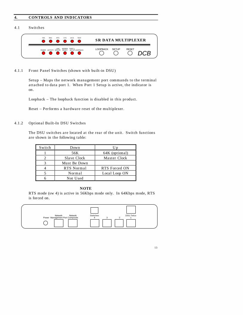
4.1.1 Front Panel Switches (shown with built-in DSU)
Setup – Maps the network management port commands to the terminalattached to data port 1. When Port 1 Setup is active, the indicator ison.
Loopback – The loopback function is disabled in this product.
Reset – Performs a hardware reset of the multiplexer.
4.1.2 Optional Built-In DSU Switches
The DSU switches are located at the rear of the unit. Switch functionsare shown in the following table:
Switch Down Up1 56K 64K (optional)2 Slave Clock Master Clock3 Must Be Down4 RTS Normal RTS Forced ON5 Normal Local Loop ON6 Not Used
NOTERTS mode (sw 4) is active in 56Kbps mode only. In 64Kbps mode, RTSis forced on.
TXD RXD RTS CTS DCD TEST
SR DATA MULTIPLEXER
LINE MODEM PORT 1POWER ACTIVITY ERROR READY SETUP LOOPBACK LOOPBACK SETUP RESET
DCB
Network Network Switches DSU TelcoPower Management Port Composite 4 3 2 1

14
For normal operation with a telephone company line, set the DSU forSLAVE clock timing (switch position 2 DOWN). For in-house linedriver applications (56K only), set the host DSU for MASTER timing(switch position 2 UP). The remote unit should remain set for Slaveclock.
4.2 Multiplexer Indicators
POWER – is ON when the SR is connected to power.
ACTIVITY – three states:
ON – multiplexing mode with no data activity.
FLICKERING – multiplexing mode with data activity (theACTIVITY indicator flickers off for every 16 blocks of data).
FLASHING SLOWLY – the multiplexer has lost communicationwith the local frame relay network. If LINE ERROR is alsoflashing, Data Carrier Detect has been lost indicating a majorcomposite link problem.
LINE ERROR – flashes when an error is detected in received data.
MODEM READY – four states:
ON – Data Carrier Detect and Clear to Send are present from thecomposite link device indicating an active composite link.
FAST FLASHING – composite link is active but there are 10 blocksof data outstanding without a response from the remotemultiplexer.
SLOW FLASHING – composite link modem is retraining andflashing Data Carrier Detect or Clear to Send upon each retrainindicating a problem with the composite link.
OFF – Data Carrier Detect or Clear to Send is not present from thecomposite modem or DSU/CSU indicating a problem with thecomposite link.
PORT 1 SETUP – is ON when the network management port functionshave been mapped to data port 1 by depressing the front panelswitch. To return these functions to the network management port,depress the front panel switch again.
LOOPBACK – The loopback function is disabled in this product.

15
The following table shows the relationship between composite DCD andCTS and the front panel MODEM READY and ACTIVITY indicators.
DCD CTS MODEM READY ACTIVITY
HI HI ON ON
LO LO OFF Flash
LO HI OFF Flash
HI LO OFF ON
4.3 Optional DSU/CSU Indicators
TxD Flashing Data is being sent over the link.RxD Flashing Data is being received from the link.RTS ON
OFFForced on or high from the multiplexer.No RTS from the multiplexer.
CTS Follows RTS CTS signal to the multiplexer.DCD ON
OFFNormal condition.No carrier signal received from the far end.
TEST ONFlashing
Unit is in loopback (DIP switch 5 UP)Telephone line in loopback.

16
5. NETWORK MANAGEMENT PORT
5.1 Introduction
The Network Management port (NMP) is used to configure the SRmultiplexer for proper operation. This connection must be used toconfigure the SR composite and data ports. The NMP can also be usedto configure remote SR ports after a link is established between the hostand remote sites.
5.2 Connections and Setup
Connection to the NMP is made either through a port on the rear of themultiplexer or by using Port 1 Setup.
5.2.1 Port 1 Setup
The easiest way to access the NMP functions is by using a terminalconnected to port 1 of the multiplexer. A switch located on the frontpanel performs this function. See paragraph 4.1.1 for information. Thisoption cannot be used if a printer is connected to port 1.
5.2.2 Dedicated Terminal or PC
The NMP functions are also available through a port on the rear of theunit labeled Network Management Port. To connect a dedicatedterminal to this port, use the green cable provided and the appropriateadapter for either a terminal or PC. Set the terminal device for 9600bps, 8 data bits, no parity, one stop bit and no flow control.
5.2.3 Dedicated Modem
For remote access to NMP functions, a dial-up modem may beconnected to the Network Management Port. You must fix the DTEinterface speed of the modem at 9600 bps, 8 data bits, no parity and onestop bit. Refer to your modem manual for appropriate setup procedures.Use the appropriate cable from paragraph 6.3.3 for connection.

17
5.3 Using the Network Management port
To activate the NMP, press the ENTER key. When you see AT YOURCOMMAND >>, the NMP is active and ready for your commands.Type H <Enter> to display the command set.
5.4 Commands
5.4.1 Help (H or ?)
COMMAND LOCAL REMOTE PARAGRAPH
Show: Config SC RSC 5.4.2Network SN 5.4.3FR Status SS RSS 5.4.4
Change: Port Config CP RCP 5.4.5MUX Param CO RCO 5.4.6FR Config FR 5.4.7
Set ID ID RID 5.4.8Activity Counters/Zero AC/Z RAC 5.4.9Flow Control FC 5.4.10Test Tools TT 5.4.14Type TY RTY 5.4.11Repeat Last Command * 5.4.12Disconnect NMP BYE 5.4.13
This Help screen shows the choice of commands available. Thecommands allow you to display the selected options (Show network andconfiguration), configure the SR (Configure ports and Set ID), andperform many different diagnostic functions such as send a testmessage, monitor data, perform loopbacks, show flow control state,show activity and other useful tests.
5.4.2 Show (Port) Configuration
The Show Config (SC) command shows the current port configurationsettings for either the local or the remote (RSC) ports. Port numbersmay be included with this command to limit the display range. If noport numbers are included, settings for all ports are shown. Use thiscommand to verify proper port configuration.

18
NOTE
Several commands allow port numbers or port numberranges to be included on the command line. When portnumbers are included, the syntax is as follows:
(Command)1 Port 1(Command)1,2,6 Ports 1, 2 & 6(Command)1 2 6 Ports 1, 2 & 6(Command)2-6 Ports 2 thru 6(Command)1,5-8 Ports 1 and 5 thru 8
5.4.3 Show Network (Configuration)
The Show Network (SN) command displays the current network(composite port) configuration and multiplexer mode of operation.
Configuration parameters include SYNC or ASYNC, LEASED LINE orDIAL-UP and ERROR CORRECTION ON or OFF.
Operating modes are OFF LINE, ON-LINE MUXING, and LOOPBACKMUXING.
5.4.4 Show Frame Relay Status
The Show Status (SS) command displays a report of frame relaystatistics including error status.
5.4.5 Change Port Configuration
The Change Port Config (CP / RCP) command sets the data portloopback, flow control and rate configuration for each data port. Followthe prompts and examples on the screen to select the port(s) andparameter(s) you wish to change. One or more ports may be set with asingle command by selecting a range of port numbers. The factorydefault setting is Xon/Xoff Space, 9600 bps.

19
5.4.6 Change Multiplexer Parameters
The CO / RCO command allows configuration of global data portparameters. These include RTS Data Gate and Data Carrier Detect.For most systems, these settings will never have to be changed.
The RTS Data Gate is used to insure that no data is transmitted from adata port unless RTS is high from the attached device. This willsometimes stop “streaming” ports.
The state of Data Carrier Detect is critical to proper operation of somehost computers. Many computers depend on DCD to issue loginprompts. If your host does not issue logins properly, you may need tochange this setting.
5.4.7 Change Frame Relay Configuration
The Frame Relay (FR) command is used to set the frame relayparameters. A list of current settings is displayed followed by promptsfor new settings. To change a setting, follow the prompts. If thecurrent setting is correct, press <Enter> to leave the setting unchanged.
5.4.8 Set ID
The Set ID (ID / RID) command allows you to set or change either thelocal or remote multiplexer identifier. IDs can be a maximum of 15characters in length. Pressing <Enter> with no entry will leave the IDunchanged.
5.4.9 Activity Counts / Zero
The Activity Counts (AC / RAC) command shows transmit and receivedata statistics for all ports. The data are presented in terms of blocks ofinformation sent and received by the network and each data port. Errorcounts are also shown. A range of ports may be included with thiscommand to reduce the number of ports shown.
The Z command is used to zero the counters so that current activity canbe monitored.

20
5.4.10 Flow Control
The Flow Control (FC) command displays the current port flow controlstatus for both local and remote ports. A port range may be includedwith this command.
5.4.11 Type
The Type (TY) command displays information about the localmultiplexer including firmware version, number of ports andmultiplexer ID. The Remote Type (RTY) command is used to displaysimilar information about the remote multiplexer.
5.4.12 Repeat Last Command
To repeat the last command, simply press the * key. This is handy forrepeating screens of constantly changing data.
5.4.13 Disconnect NMP
The BYE command toggles the CTS output from the NetworkManagement port. This is used to disconnect equipment such as dial-upmodems or the DCB Access Switch.
21
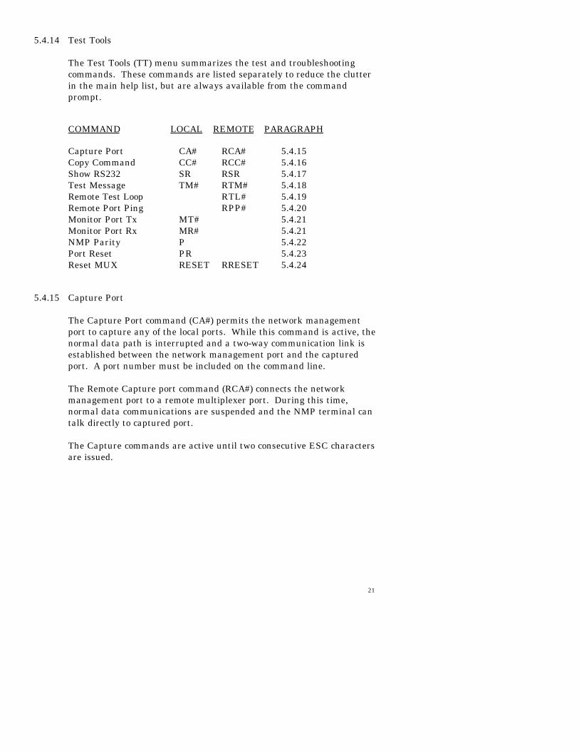
5.4.14 Test Tools
The Test Tools (TT) menu summarizes the test and troubleshootingcommands. These commands are listed separately to reduce the clutterin the main help list, but are always available from the commandprompt.
COMMAND LOCAL REMOTE PARAGRAPH
Capture Port CA# RCA# 5.4.15Copy Command CC# RCC# 5.4.16Show RS232 SR RSR 5.4.17Test Message TM# RTM# 5.4.18Remote Test Loop RTL# 5.4.19Remote Port Ping RPP# 5.4.20Monitor Port Tx MT# 5.4.21Monitor Port Rx MR# 5.4.21NMP Parity P 5.4.22Port Reset PR 5.4.23Reset MUX RESET RRESET 5.4.24
5.4.15 Capture Port
The Capture Port command (CA#) permits the network managementport to capture any of the local ports. While this command is active, thenormal data path is interrupted and a two-way communication link isestablished between the network management port and the capturedport. A port number must be included on the command line.
The Remote Capture port command (RCA#) connects the networkmanagement port to a remote multiplexer port. During this time,normal data communications are suspended and the NMP terminal cantalk directly to captured port.
The Capture commands are active until two consecutive ESC charactersare issued.
22
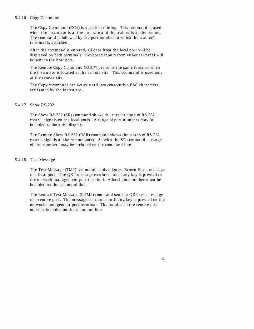
5.4.16 Copy Command
The Copy Command (CC#) is used for training. This command is usedwhen the instructor is at the host site and the trainee is at the remote.The command is followed by the port number to which the trainee’sterminal is attached.
After the command is entered, all data from the local port will bedisplayed on both terminals. Keyboard inputs from either terminal willbe sent to the host port.
The Remote Copy Command (RCC#) performs the same function whenthe instructor is located at the remote site. This command is used onlyat the remote site.
The Copy commands are active until two consecutive ESC charactersare issued by the instructor.
5.4.17 Show RS-232
The Show RS-232 (SR) command shows the current state of RS-232control signals on the local ports. A range of port numbers may beincluded to limit the display.
The Remote Show RS-232 (RSR) command shows the status of RS-232control signals at the remote ports. As with the SR command, a rangeof port numbers may be included on the command line.
5.4.18 Test Message
The Test Message (TM#) command sends a Quick Brown Fox... messageto a local port. The QBF message continues until any key is pressed onthe network management port terminal. A local port number must beincluded on the command line.
The Remote Test Message (RTM#) command sends a QBF test messageto a remote port. The message continues until any key is pressed on thenetwork management port terminal. The number of the remote portmust be included on the command line.

23
5.4.19 Remote Test Loop
The Remote Test Loop (RTL#) command is used to test a data path fromend to end. This command enables port loopback in the remotemultiplexer, then sends a test message to that port. If everything isworking correctly, the test message is displayed on the networkmanagement port terminal. A remote port number must be included onthe command line.
5.4.20 Remote Port Ping
The Remote Port Ping (RPP#) command measures the echo time of asingle character, on the selected port, and displays the result inmilliseconds. This information is useful when troubleshooting theframe relay network. Excessive delay may indicate problems with thenetwork configuration. To stop pinging, press any key.
5.4.21 Monitor Port TX or RX
The Monitor Port TX (MT#) command monitors data transmitted fromthe selected port to the corresponding port of the remote multiplexer.The Monitor Port RX (MR#) command monitors data received by theselected port from the corresponding port of the remote multiplexer. Alocal port number must be included on the command line.
When port monitor is active, two ESC characters are needed to end thetest.
5.4.22 NMP Parity
The NMP Parity command (P) sets the parity for the networkmanagement port. The factory default is SPACE (8,N,1).
5.4.23 Port Reset
The Port Reset (PR) command is used to reset flow control to hungports. A range of local port numbers or ALL may be included with thiscommand. Flow control leads at both the local and remote ports arereset.

24
5.4.24 Reset Mux
The Reset Mux (RESET) command performs a local multiplexer reset.To reset the remote multiplexer use RRESET.

25
6. INTERFACE SIGNALS AND CABLING
6.1 Connector Location and Pin Reference
SR 4 Rear Panel and RJ-45 Jacks
RJ-45 Plug Positions
1 2 3 4 5 6 7 8
1234DSU TelcoSwitchesNetwork Network
Power Management Port Composite
26
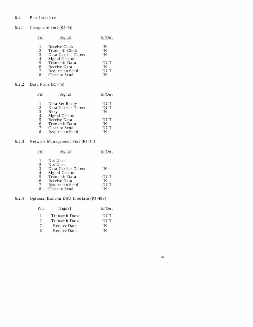
6.2 Port Interface
6.2.1 Composite Port (RJ-45)
Pin Signal In/Out
1 Receive Clock IN2 Transmit Clock IN3 Data Carrier Detect IN4 Signal Ground5 Transmit Data OUT6 Receive Data IN7 Request to Send OUT8 Clear to Send IN
6.2.2 Data Ports (RJ-45)
Pin Signal In/Out
1 Data Set Ready OUT2 Data Carrier Detect OUT3 Busy IN4 Signal Ground5 Receive Data OUT6 Transmit Data IN7 Clear to Send OUT8 Request to Send IN
6.2.3 Network Management Port (RJ-45)
Pin Signal In/Out
1 Not Used2 Not Used3 Data Carrier Detect IN4 Signal Ground5 Transmit Data OUT6 Receive Data IN7 Request to Send OUT8 Clear to Send IN
6.2.4 Optional Built-In DSU Interface (RJ-48S)
Pin Signal In/Out
1 Transmit Data OUT2 Transmit Data OUT7 Receive Data IN8 Receive Data IN
27
12345678
682073254
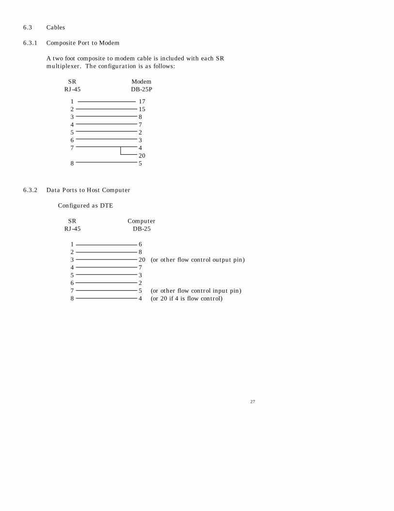
6.3 Cables
6.3.1 Composite Port to Modem
A two foot composite to modem cable is included with each SRmultiplexer. The configuration is as follows:
SR ModemRJ-45 DB-25P
6.3.2 Data Ports to Host Computer
Configured as DTE
SR ComputerRJ-45 DB-25
(or other flow control output pin)
(or other flow control input pin)(or 20 if 4 is flow control)
1234567
8
171587234205

28
6.3.2 Data Ports to Host Computer, continued
Configured as DCE
SR ComputerRJ-45 DB-25
(or 4 if 20 is flow control)(or other flow control output pin)
(or other flow control input pin)
To a PC Com Port
SR ComputerRJ-45 DB-25S DE-9S
12345678
20572348
12345678
6 or 68 or 14 or 77 or 53 or 22 or 35 or 820 or 4
29
34567
8
87234205
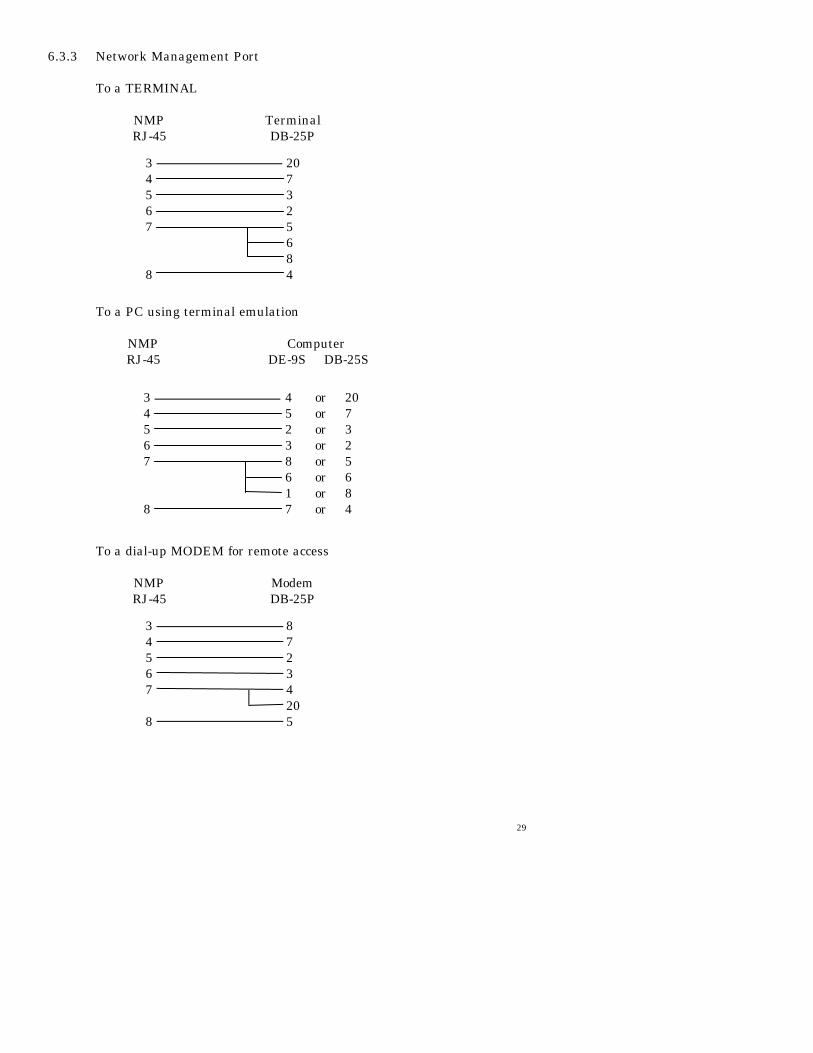
6.3.3 Network Management Port
To a TERMINAL
NMP TerminalRJ-45 DB-25P
To a PC using terminal emulation
NMP ComputerRJ-45 DE-9S DB-25S
To a dial-up MODEM for remote access
NMP ModemRJ-45 DB-25P
207325684
34567
8
4 or 205 or 72 or 33 or 28 or 56 or 61 or 87 or 4
34567
8

30
6.4 Signal Paths through Multiplexers
The following diagram shows the signal flow between data ports of twoSR multiplexers.
Host Remote
Transmit Data to Receive Data is the normal required path for dataflow.
RTS to DCD is a hardware handshake path used to wake up the remotedevice. Many host computers require DCD to issue a login prompt.
Busy to CTS is the hardware flow control path. For CTS/Busy flowcontrol, the hardware flow control pin of the attached device must bewired to Busy on the multiplexer.
The DSR output of the multiplexer port is always asserted (high).
TxD
RxD
RTS
CTS
DSR
DCD
BUSY
TxD
RxD
RTS
CTS
DSR
DCD
BUSY

31
7. TROUBLESHOOTING
7.1 General Approach
When troubleshooting problems, a rational plan can save you manyhours of frustration. The following is a brief outline of standardtroubleshooting procedures.
1. Gather the facts to determine the exact nature of the problem. 2. Draw a picture of the system showing the equipment at both
the host and remote ends and the phone lines or in-housewiring. Use this as a reference to note your observations, teststeps and test results. A picture keeps you focused and oftensaves duplicate effort.
3. Record the front panel indications before changing anything.
This is an important part of fact gathering 4. If you change anything, change only one thing at a time. 5. Use the built-in test functions and record your results.
7.2 Loopback Tests
It is best to begin loopback testing at the remote terminal and worktoward the host. If all the loopbacks are successful, the datacommunications equipment and the terminal are working correctly.
Put the remote multiplexer port in loopback and have someone typealpha characters on the keyboard of the affected terminal. If thecharacters appear correctly on the screen, the port is working. Nextloop the associated port of the host multiplexer. If characters againappear correctly, the communications link and the ports on bothmultiplexers are working correctly. The problem then is with the hostcomputer port or the cable between the host computer and themultiplexer.
Port loopbacks can be turned on and off from the Network Managementport of the multiplexer. If a NMP terminal is not available, portloopback can be enabled using the Port 1 Setup function of the remotemultiplexer
32
7.3 Installation Troubleshooting, DSUs
First, set up the DSUs without connecting the multiplexers. The DSUsshould be set to constant carrier, also called forced Request To Send, orconstant RTS.
Carrier Detect should be ON at both locations.
7.4 Installation Troubleshooting, Multiplexers
Before trying terminals, make sure the multiplexers are able to “see”each other. Use the RTY command to verify a response from the remotemultiplexer. If you get a correct response to RTY, the link is up and themultiplexers are communicating.
7.5 Installation Troubleshooting, Terminals
Terminal problems typically fall into four categories:
1. The terminal or printer gets no data2. The terminal or printer gets “garbage” data3. Blocks of data are lost4. Terminals or printers seem to “hang”.
When a terminal gets no data, check to see the cables are wiredcorrectly and that flow control is set properly.
If the terminal gets “garbage” data, check the speeds of the host andremote multiplexers, the terminal and the computer ports to make surethey match.
Blocks of data are lost most often when data is sent to a printer or a lotof data is being displayed on a terminal. Most of these problems are dueto flow control not matching between the printer or terminal and themultiplexer.
If terminals and printers work for a while and then “hang”, check theflow control settings. When Xon/Xoff flow control is set to a differentparity on the multiplexer than on the terminal or printer, the result iseither a “hung” device that is flow controlled off but never back on, or adevice that is never flowed off causing buffer overflow and lost data.
7.6 Assistance
If you need assistance troubleshooting your system, contact DCBcustomer support at (217) 897-6600 between 8:00 am and 5:00 pmcentral time Monday through Friday.

33
8. WARRANTY
DCB multiplexers are warranted to be free of defects in materials andworkmanship for two years. Data Comm for Business will repair orreplace any equipment proven to be defective within the warrantyperiod. All warranty work is F.O.B. Dewey, IL. This warranty isexclusive of abuse, misuse, accidental damage, acts of God orconsequential damages, etc. DCB liability shall not exceed the originalpurchase price.
All equipment returned for repair must be accompanied by a ReturnedMaterial Authorization (RMA) number. To receive an RMA number, call(217) 897-6600 between the hours of 8 AM and 5 PM central time.Equipment must be shipped prepaid to DCB and will be returned at DCB'sexpense.
Ship returned items to:
Data Comm for Business2949 CR 1000EDewey, IL 61840
Data Comm for Business, Inc.PO Box 6329Champaign, IL 61826-6329
Tel (217) 897-6600Fax (217) 897-1331Email [email protected]