square threaded screws - statics for …statics.marcks.cc/friction/pdf/screw_friction.pdf · most...
TRANSCRIPT

SQUARE THREADED SCREWS
Rob Wendland, driving Mike Troxel's Federal-Mogul Dragster In-N-Out Burger
Machine Screw Jack Nosen Mechanical & Electrical Equipment Co. Limited

2
Screws A screw is a helical ridge wrapped around a shaft forming a
long circular ramp. Common uses are to fasten parts, transmit power, or provide some form of adjustment
Examples include bolting of structural steel connection plates to a girder, pipe threads for assembly and leak prevention of the joints, woodworking screws for a variety of uses, machine screws to assemble product, adjustment screws to position a table saw blade, power transmission on a worm-gear drive circular saw, plus an infinite number of other applications
Power Screws from Bornemann Gewindetechnik

3
Screws Each application requires a specific thread form. However,
most screws can be reduced to the following basic thread designs. Each design has its own strengths and weaknesses
Square threaded screws are used as a power screw. It is the most efficient design (low friction), the easiest to analyze, but the most difficult to machine.
Acme threads are also used as power screws. They are much easier to machine but only have about 70% of the efficiency of a square threaded screw. The Acme thread typically has a 29o taper
4
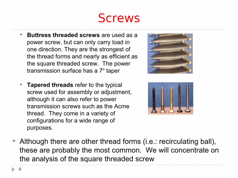
Screws Buttress threaded screws are used as a
power screw, but can only carry load in one direction. They are the strongest of the thread forms and nearly as efficient as the square threaded screw. The power transmission surface has a 7o taper
Tapered threads refer to the typical screw used for assembly or adjustment, although it can also refer to power transmission screws such as the Acme thread. They come in a variety of configurations for a wide range of purposes.
Although there are other thread forms (i.e.: recirculating ball), these are probably the most common. We will concentrate on the analysis of the square threaded screw

5
Clamp Load of Screws When the threaded fastener acts as a clamp, the screw, bolt, or
nut are tightened until snug. At this point, the bolt or screw begins to stretch and applies a clamping load to the joint.
The objective of the fastening process is to clamp parts together with more force than any external force trying to separate them. When correctly torqued, a fastener acts like a spring keeping parts under constant stress while resisting fatigue.

6
20% of Torque forStretching Bolt
40% of Torque forThread Friction
40% of Torque for Under Head Friction
When tightening a bolt – only 20% of the applied torque goes to actual clamping load for the bolt – 80% is lost due to friction under head and in the thread.
If the screw is a power screw used to carry load, there will still be up to 40% frictional loss in the threads. Collar loads will occur due to thrust and will be taken by some form of thrust bearing. Such screws are handled in a machine design course.
We will concentrate primarily on clamping loads.
Friction in Screws
6

Anatomy of a Screw Since a square threaded screw is nothing more than an inclined
plane (ramp) wrapped around a shaft, the analysis of a screw friction problem is identical to pushing a weight up a ramp
To properly construct the ramp model of the screw, we must understand the nomenclature of screw design. This includes: Pitch and Lead of the screw Major, minor, and pitch diameters The number of threads
The later refers to the number of unique thread wraps around the screw; often referred to as a start. Although most screws are single-start, double-, triple-, and even quadruple-starts are manufactured. Such multi-start or multi-threaded screws are used when a large screw advance is required for each turn of the screw
7

Anatomy of a Screw The following graphic defines typical screw nomenclature
8
Dmajor Dpitch Dminor
• Dmajor - Major diameter is measured crest to crest.• Dminor - Minor diameter is measured root to root.• Dpitch - Pitch diameter, also called nominal diameter, is
measured at a point where the width of the thread and the groove are equal
Single start Double start Triple start
Crest of threadRoot of thread
A start refers to the number of thread wraps around the 'shaft'. The threads exposed at the end of the screw is defined by one-half the pitch multiplied by the number of starts.
The pitch of a screw is the measured distance between crests of a thread. The lead of a screw is the distance the screw advances with one turn of the screw. It is equal to the pitch multiplied by the number of starts.

The Ramp Model A screw is modeled as a simple inclined plane. The horizonal
length of the ramp is the perimeter of the screw based on pitch diameter. The height of the ramp is the lead of the screw
The weight resting on the ramp is the load on the screw The force 'P' acting on the weight is horizontal. It is a fictitious
force equal to the applied torque divided by pitch radius. In other words, it is a force that if applied at the pitch radius of the screw, will create the moment of the applied torque.
9
T = Applied Torque
Dpitch=
P = T / Rpitch
Rpitch

The Ramp Model In the ramp model, if the screw is tightened, force 'P' pushes
the mass up the ramp. If the screw is loosened, the force pulls the mass down the ramp
The ramp model also illustrates whether or not a screw is self-locking. A self-locking screw is one that will not back out when torque is removed. Similarly, a screw not self-locking will 'unscrew' when torque is removed. These conditions are illustrated below and on next page
10
φθ
P
W
R
L
πDpitch
θ
The ramp in the model shown to the left has a length of πD and a height of L. The angle of the ramp will be θ which is also known as the lead angle. The mass has a weight of W equal to the load on the screw. Force P and impending motion is up the ramp indicating the screw is being tightened

The Ramp Model
11
φθ
P
W
R
φθ
P
W
R
The model to the left is for the same screw but with the screw being loosened. The friction angle φ is greater than the lead angle θ indicating a self-locking screw; it will remain in place when loaded.
The final model indicates a force applied to maintain the block in position (i.e.: a torque applied to the screw to prevent it from backing). This is a non-self locking screw which is evident by the fact φ < θ. Such screws can be used to translate linear motion to rotary motion.

Example 16 - Screws The mean diameter of the screw of the C-clamp
shown is 40 mm and the pitch is 20 mm. It is a single start screw. The body of the clamp is a titanium allow while the screw itself is 6061-T6 aluminum alloy. A torque of 160 N-m is applied to the screw. What is the resulting clamping force? What torque is necessary to release
the clamp?
12
Example 16 - Screws
13
φθ
8000 N
W
R
20 mm
125.7 mm
θ
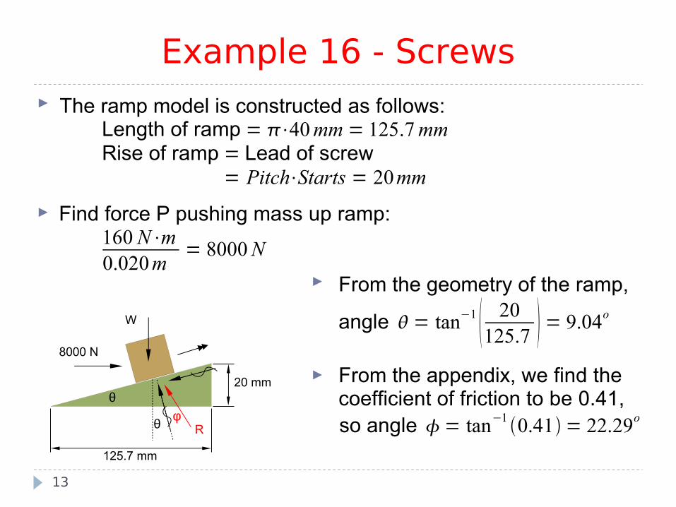
The ramp model is constructed as follows:Length of ramp = ⋅40mm= 125.7mmRise of ramp = Lead of screw
= Pitch⋅Starts = 20mm
Find force P pushing mass up ramp:160 N⋅m0.020m
= 8000N
From the geometry of the ramp,
angle = tan−1 20125.7 = 9.04o
From the appendix, we find thecoefficient of friction to be 0.41,so angle = tan−1
0.41 = 22.29o

Example 16 - Screws Solving analytically:
14
F x= 0 = 8000⋅cos9.04 − W⋅sin 9.04 − F
. . . F = 7900 − W⋅sin 9.04
F y = 0 =−8000⋅sin 9.04 − W⋅cos9.04 N
. . . N = 1257 W⋅cos9.04
tan =FN
=
0.41 =7900−W⋅sin 9.04 1257W⋅cos9.04
515.40.405⋅W = 7900 − 0.157⋅W0.562⋅W = 7385 N
W = 13,140 N (Clamping Force)
125.7 mm
x
φθ
8000 N
W
R
20 mmθ
y Wx
Wy
Px
Py
F
N
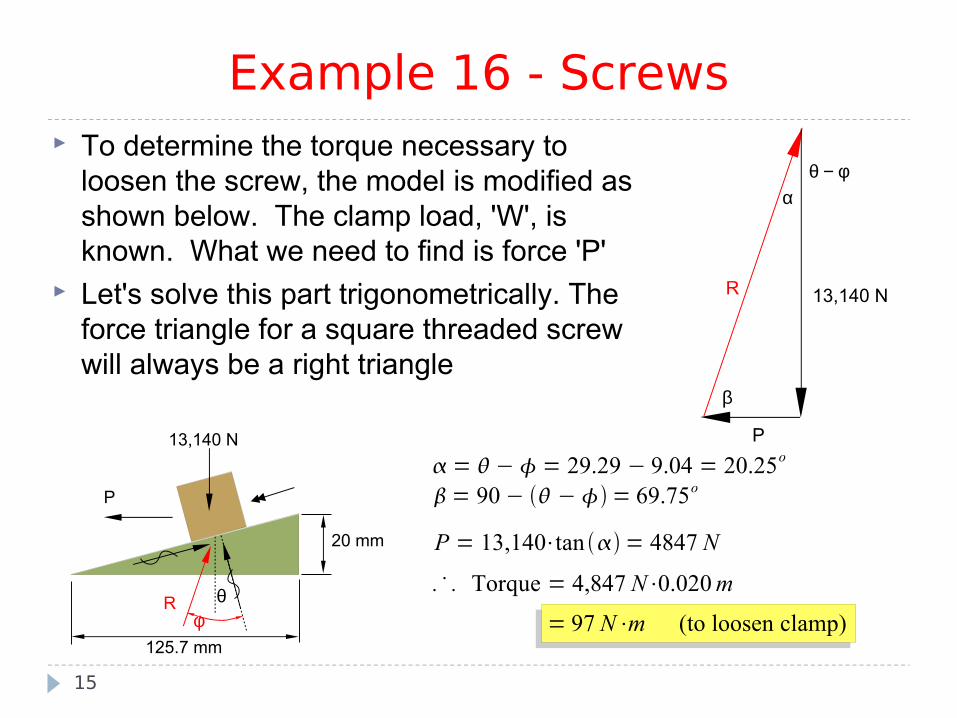
Example 16 - Screws To determine the torque necessary to
loosen the screw, the model is modified as shown below. The clamp load, 'W', is known. What we need to find is force 'P'
Let's solve this part trigonometrically. The force triangle for a square threaded screw will always be a right triangle
15
= − = 29.29 − 9.04 = 20.25o
= 90 − − = 69.75o
P = 13,140⋅tan = 4847 N
. . . Torque = 4,847 N⋅0.020m
= 97 N⋅m (to loosen clamp)φθ
P
13,140 N
R
125.7 mm
20 mm
13,140 N
P
R
θ − φα
β

Example 17 - Screws The coefficient of friction for the worm
gear shown is 0.10. Determine the torque applied to the worm gear to rotate the large gear CCW. Assume the 900 N.m torque is constant.
16
300 mm
900 N.m
40 mm
Optimas Worm Gear Set

Example 17 - Screws The ramp model is constructed as follows:
17
300 mm
900 N.m
40 mm
Optimas Worm Gear Set
Length = 80⋅mmRise = Pitch⋅Starts = 10mm
W =900N⋅m0.300m
= 3000N
= tan−1 1080⋅ = 2.28o
= tan−10.10 = 5.7o

Example 17 - Screws
18
φθ
P
3000 N
R
10 mm
80π mm
θ
α
β
P
R3000 N
= = 7.98o
= 90 − = 82.02o
3000sin 82.02
=P
sin 7.98
P = 420.6 N
Torque = 420.6 N⋅0.04m= 16.8N⋅m
Alternatively:
F x= P⋅cos − 3000⋅sin − F F = 0.999⋅P − 119.3 F y =−P⋅sin − 3000⋅cos N N = 0.040⋅P 2997
tan = = 0.10 =FN
=0.999⋅P − 119.30.040⋅P 2997
0.0040⋅P 299.7 = 0.999⋅P − 119.3 P = 421 NTorque = 421 N⋅0.04m
= 16.8 N⋅m