sqdc synqnet dc drive - welcome to mei's on-line...
TRANSCRIPT

SqDC SynqNet
DC Drive
Operating Instructions Version 1 - 03/07
Valid for HW/SW Version 1.0
Keep all product manuals as a product component during the life span of the product.
Pass all product manuals to future users/owners of the product
KOLLMORGEN DC DRIVE ver 1 B109 PV 04 2 MAR 2007.doc

KOLLMORGEN Version 1 -11/07 Revision History
SqDC SynqNet DC Drive i
Revision History
Rev Date Valid For Description
1.0 OCT 2006 HW/SW Versions 1.0 New Quick start Guide
1.1 FEB 2007 same Quick Start Guide rewritten
Important Notice
Copyright Kollmorgen Servotronix Ltd 2007
Kollmorgen Servotronix Ltd holds the copyright to this manual. All rights are reserved
and no part of this publication may be reproduced or transmitted in any form or by any means
without prior written consent from Kollmorgen Servotronix Ltd.
Disclaimer
The information in this manual was accurate and reliable at the time of its release. However,
Kollmorgen Servotronix Ltd. reserves the right to change the specifications of the product described in this manual without notice at any time.
This document contains proprietary and confidential information of Kollmorgen Servotronix Ltd. The contents of the document may not be disclosed to third parties, translated, copied or
duplicated in any form, in whole or in part, without the express written permission of
Kollmorgen Servotronix Ltd.
Registered Trademarks
All other proprietary names mentioned in this manual are the trademarks of their respective
owners.
Print Version 004
March 2007

KOLLMORGEN Version 1 -11/07 Important Safety Information
SqDC SynqNet DC Drive ii
How to Contact Us
Danaher Motion is committed to quality customer service. Our goal is to provide
the customer with information and resources as soon as they are needed. In
order to serve in the most effective way, contact your local sales representative
for order status and delivery information, product information and literature,
and application and field technical assistance. If you are unaware of who your
local sales representative is, please contact us at:
Email: [email protected] and specify SynqNet Support in the subject
line.
Important Safety Information
The information found in this section is designed for your safety and the
prevention of needless repairs to the machine.
Operational Warnings and Cautions
DANGER
Danger means that the situation described will cause death or injury to
you or someone else if the safety information is not obeyed.
NOTE
Please take note of the fact that…...
CAUTION
Caution means that the situation described could cause damage to the
equipment or the program.
WARNING
Warning means that the situation described can cause damage to either
the equipment or the program and we recommend that only an
experienced operator should perform these adjustments.
KOLLMORGEN Version 1 -11/07 Contents
SqDC SynqNet DC Drive iii
Contents
REVISION HISTORY ..................................................................................................I
IMPORTANT NOTICE .................................................................................................I
HOW TO CONTACT US ............................................................................................ II
IMPORTANT SAFETY INFORMATION ............................................................................ II
Operational Warnings and Cautions.................................................................. ii
1 INTRODUCTION ...............................................................................................................1
1.1 ABOUT THIS GUIDE.........................................................................................1
1.1.1 Downloading Manuals from our Website ............................................... 1
2 PRE-INSTALLATION REQUIREMENTS .........................................................................3
2.1 LAB ELECTRICAL REQUIREMENTS .....................................................................3
2.2 REQUIRED CABLES ........................................................................................3
2.3 MOTION CONTROL CARD (DMPC) ....................................................................4
2.3.1 What is SynqNet.................................................................................. 4
2.3.2 Acquiring the Latest SynqNet Software Version ..................................... 4
2.3.3 PC Requirements ................................................................................ 4
3 INSTALLING THE HARDWARE ......................................................................................5
3.1 UNPACKING INSTRUCTIONS ..............................................................................5
3.2 GENERAL .....................................................................................................6
3.2.1 Safety ................................................................................................. 6
3.2.2 Grounding ........................................................................................... 6 3.3 CONNECTING THE DRIVE CABLES......................................................................7
4 INSTALLING THE DMPC CONTROLLER CARD............................................................8
4.1 INSTALLING THE DMPC CONTROLLER CARD .......................................................8
4.2 INSTALLING THE DMPC DRIVERS ......................................................................8
4.3 INSTALLING THE MOTION CONSOLE PROGRAM...................................................12
5 USING THE MOTION CONSOLE...................................................................................13
5.1 LOADING THE MOTION CONSOLE.....................................................................13
5.2 CONFIGURING THE MOTOR PARAMETERS..........................................................17
5.2.1 Uploading the Motor Parameters (get command) ................................. 17
5.2.2 Editing the Motor Configuration File .................................................... 18
5.2.3 Downloading the Motor Parameters (Set command) ............................ 19 5.3 CONFIGURING THE MOTION CONTROL CONSOLE ................................................19
5.3.1 Mapping the Axes .............................................................................. 20
5.3.2 Setting the Filter Parameters (PID Coefficients) ................................... 20
5.3.3 Setting the Motor Configuration Parameters ........................................ 21
5.3.4 Clearing the Errors............................................................................. 23
5.3.5 Setting the Axes Motion Parameters ................................................... 23
5.3.6 Set Amp Enable ................................................................................ 24
5.3.7 Start and Stop the Motors................................................................... 25
KOLLMORGEN Version 1 -11/07 Contents
SqDC SynqNet DC Drive iv
6 ERROR MESSAGES ......................................................................................................26
6.1 USING THE SQDRIVEMSG UTILITY....................................................................26
6.1.1 Example............................................................................................ 27
6.1.2 Error Messages ................................................................................. 27
APPENDIX A HARDWARE SPECIFICATIONS....................................................................................28
A.1 MECHANICAL ..............................................................................................28
A.1.1 Physical Characteristics ..................................................................... 28
A.1.2 Front Panel ....................................................................................... 28
A.1.3 Weight .............................................................................................. 28 A.2 ELECTRICAL SPECIFICATIONS.........................................................................29
A.3 ENVIRONMENTAL SPECIFICATIONS...................................................................30
APPENDIX B CONFIGURATION FILE PARAMETERS .......................................................................31
B.1 PEAK CURRENT LEVEL .................................................................................31
B.2 HEAT-SINK TEMPERATURE.............................................................................32
B.3 BUS VOLTAGE.............................................................................................32
APPENDIX C ENCODERS ....................................................................................................................33
C.1 INCREMENTAL ENCODERS .............................................................................33
C.1.1 Single Ended ABI Encoders ............................................................... 33
C.1.2 Differential ABI Encoders ................................................................... 34 C.2 ABSOLUTE ENCODERS..................................................................................34
APPENDIX D CONNECTOR PIN-OUTS ...............................................................................................35
D.1 LOGIC POWER.............................................................................................35
D.2 BUS POWER ...............................................................................................35
D.3 MOTOR CONNECTOR ....................................................................................36
D.4 ENCODER CONNECTOR .................................................................................36

KOLLMORGEN Version 1 -11/07 Introduction
SqDC SynqNet DC Drive 1
Chapter 1
1 INTRODUCTION
1.1 About this Guide This guide is written for integration engineers that want to create a working
environment on the test bench. Installation and step by step setup instructions
are included.
A more detailed description of the system is provided in the SqDC Technical
Manual which is included together with our applications notes, in Acrobat-
Reader format on the accompanying CD-ROM in multiple languages. You can
print out this documentation on any standard commercial printer. You can also
purchase a printed copy of the documentation from us at the following E-mail
address [email protected] and specify SynqNet Support in the subject
line.
It is strongly recommended that only suitable personnel install and setup the
system.
1. The guide is divided into the following sections
2. Unpacking the Drive
3. Drive Hardware Setup
4. SynqNet Installation
5. Configuring the SynqNet Motion Console
6. Configuring the Drive Parameters
7. Operating the Drive
1.1.1 Downloading Manuals from our Website You can use the link www.DanaherMotion.com to download our product
manuals from the DanaherMotion website.
KOLLMORGEN Version 1 -11/07 Installing Hardware
SqDC SynqNet DC Drive 2
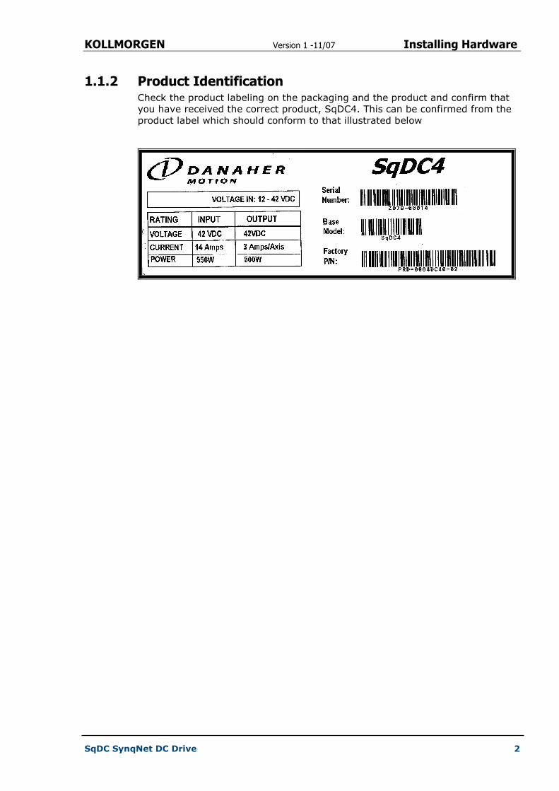
1.1.2 Product Identification Check the product labeling on the packaging and the product and confirm that
you have received the correct product, SqDC4. This can be confirmed from the
product label which should conform to that illustrated below
KOLLMORGEN Version 1 -11/07 Pre-Installation Requirements
SqDC SynqNet DC Drive 3
Chapter 2
2 PRE-INSTALLATION REQUIREMENTS
This section describes all the equipment required to test drive the stepper drive.
2.1 Lab Electrical Requirements The following equipment must be readily available in order to install and setup
the SqDC SynqNet DC Drive and the SynqNet PC controller.
Table 1: Electrical Requirements
Requirement Description
Bus Power Supply
Power Supply Type Unregulated or Regulated
Output Voltage 12 to 42 Volts
Output Current 1.5 to 10 Amps
The output current depends on motor selection, load and power supply voltage.
Current Limit Adjustable
Logic Power Supply
Power Supply Type Regulated
Output Voltage 24V +-10%
Output Current 1A
DC Motors???
DC Motor Type Permanent Magnet Brushed DC (PMDC)
Voltage 0 - 42 Vdc
Current 3A rms (MAX), 4.5A peak (MAX)
2.2 Required Cables See Appendix D Connector Pin-Outs on page 35 for the information required to
build the cables

KOLLMORGEN Version 1 -11/07 Pre-Installation Requirements
SqDC SynqNet DC Drive 4
2.3 Motion Control Card You need to acquire a SynqNet PC controller card from Danaher Motion
Performance Controls (DMPC) as the motion control of the motor is performed
by this card.
2.3.1 What is SynqNet SynqNet is a high-performance; synchronous network technology specifically
designed for multi-axis motion control applications. It is the only system that
dramatically reduces system wiring while simultaneously provides higher
performance than conventional analog control systems.
2.3.2 Acquiring the Latest SynqNet Software Version You must download the latest version of the SynqNet MPI software for your
card from the DMPC support site. Use the Download tab on the website.
When downloading the software you are prompted to get a password to unzip
the downloaded file.
NOTE
The MPI-setup version must be 03.04.00 or later.
For further details please visit to the Danaher Motion Performance Controls
Website: http://www.motioneng.com/
2.3.3 PC Requirements Any PC running:
� Microsoft Windows 2000 or better
� Acrobat reader version 5 or better
� Internet browser (IE recommended)

KOLLMORGEN Version 1 -11/07 Installing the Hardware
SqDC SynqNet DC Drive 5
Chapter 3
3 INSTALLING THE HARDWARE
This section includes the:
� Unpacking the hardware
� General information on installing the SynqNet system
� IMPORTANT safety information
� Grounding information
� Connecting the drive cables
3.1 Unpacking Instructions Upon receipt of the equipment, inspect the components to ensure that no
damage has occurred during shipment. If damage has occurred, notify the
carrier immediately. Check all shipping material for connector kits,
documentation, diskettes, CD-ROM, or other small pieces of equipment before
disposing of the packing material.
IMPORTANT INFORMATION
Do not dispose of shipping materials until the packing list has been
thoroughly checked and all items accounted for.
When removing all packing material and equipment from the shipping
container be aware that some of the shipped items may be small enough
to be accidentally discarded.
ESD WARNING
Electronic components in this equipment are design-hardened to reduce
sensitivity to ESD (Electro Static Discharge) however, proper procedures
should be taken when handling the equipment to avoid any damage.
KOLLMORGEN Version 1 -11/07 Installing the Hardware
SqDC SynqNet DC Drive 6
3.2 General These installation steps are designed to lead you through the proper installation
and setup of the SynqNet system. They were developed with the assumption
that you have a fundamental understanding of basic electronics, computers,
mechanics, and proper safety practices. However, you do not have to be an
expert in motion control to install and operate the drive system. It is
recommended that you read the entire manual completely before attempting
installation or operating the equipment.
3.2.1 Safety
DANGER
High voltages could be present as well as dangerous and hazardous
conditions.
Be certain to follow all national and local codes during installation.
3.2.2 Grounding System grounding is essential for proper performance of the drive system. A
ground bus bar may be used as a single point ground for the system. Safety
grounding should be provided to all pieces of the system from a star point. In
addition to the safety grounding, a high frequency ground must be provided
that connects the back panel to the enclosure and, ultimately, to earth ground.
The objective is to provide an extremely low impedance path between the
filters, drives, power supplies, and earth ground.
This high frequency ground is accomplished with the use of a flat braid or
copper bus bar. It is important not to rely on a standard wire for the high
frequency ground. In general, a wire has an inductance of 8nH-per-inch,
regardless of diameter. At higher frequencies because the voltage runs on the
surface of the conductor, this unwanted inductance between grounds equates to
limited filter performance.
NOTE
When connecting high frequency grounds, use the shortest braided ribbon
or braided cable as possible.
KOLLMORGEN Version 1 -11/07 Installing the Hardware
SqDC SynqNet DC Drive 7
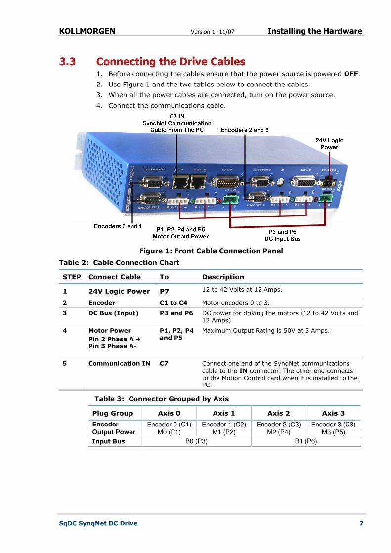
3.3 Connecting the Drive Cables 1. Before connecting the cables ensure that the power source is powered OFF.
2. Use Figure 1 and the two tables below to connect the cables.
3. When all the power cables are connected, turn on the power source.
4. Connect the communications cable.
Figure 1: Front Cable Connection Panel
Table 2: Cable Connection Chart
STEP Connect Cable To Description
1 24V Logic Power P7 12 to 42 Volts at 12 Amps.
2 Encoder C1 to C4 Motor encoders 0 to 3.
3 DC Bus (Input) P3 and P6 DC power for driving the motors (12 to 42 Volts and 12 Amps).
4 Motor Power
Pin 2 Phase A + Pin 3 Phase A-
P1, P2, P4 and P5
Maximum Output Rating is 50V at 5 Amps.
5 Communication IN C7 Connect one end of the SynqNet communications
cable to the IN connector. The other end connects to the Motion Control card when it is installed to the PC.
Table 3: Connector Grouped by Axis
Plug Group Axis 0 Axis 1 Axis 2 Axis 3
Encoder Encoder 0 (C1) Encoder 1 (C2) Encoder 2 (C3) Encoder 3 (C3) Output Power M0 (P1) M1 (P2) M2 (P4) M3 (P5)
Input Bus B0 (P3) B1 (P6)
KOLLMORGEN Version 1 -11/07 Installing MEI Controller Card
SqDC SynqNet DC Drive 8
Chapter 4
4 INSTALLING THE DMPC CONTROLLER CARD
This section installs the:
� DMPC Controller card
� The DMPC Drivers
� SynqNet communication cable that is connected to the drive
4.1 Installing the DMPC Controller Card 1. Install the SynqNet motion controller card using the instructions you
received from the manufacturer.
2. Connect the communication cable that has one side connected to the motor
drive to the OUT connector on the newly installed SynqNet card.
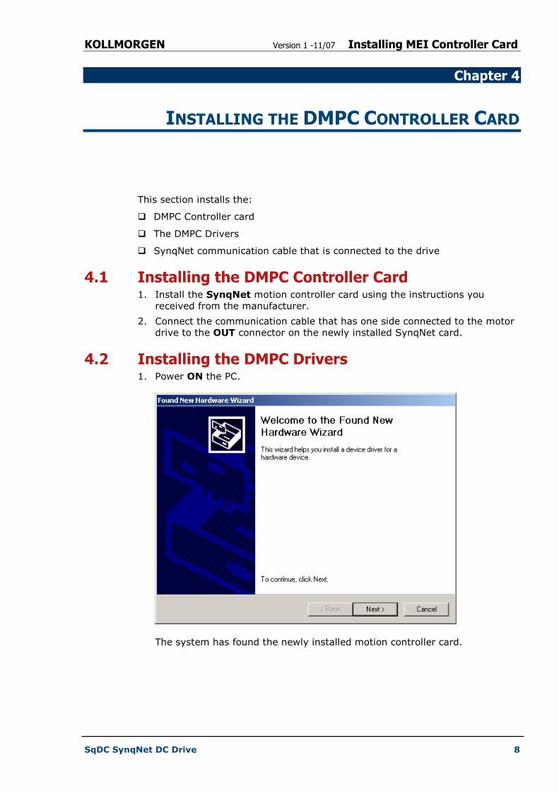
4.2 Installing the DMPC Drivers 1. Power ON the PC.
The system has found the newly installed motion controller card.
KOLLMORGEN Version 1 -11/07 Installing MEI Controller Card
SqDC SynqNet DC Drive 9
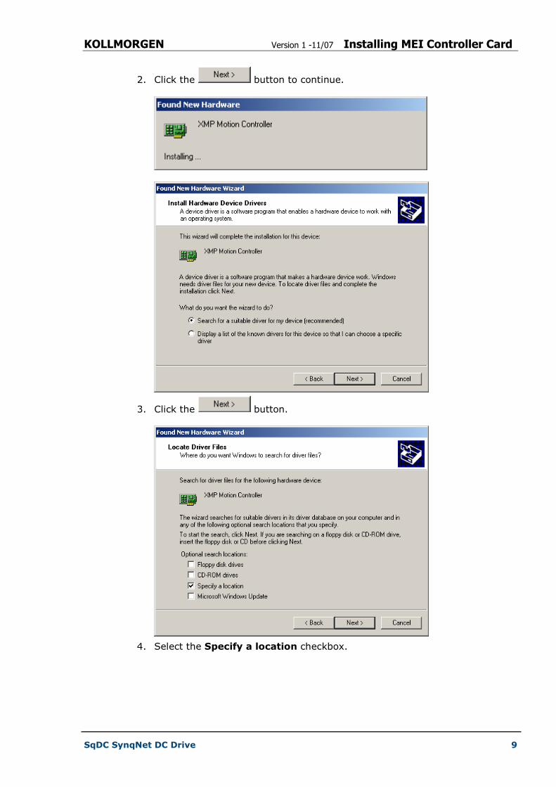
2. Click the button to continue.
3. Click the button.
4. Select the Specify a location checkbox.
KOLLMORGEN Version 1 -11/07 Installing MEI Controller Card
SqDC SynqNet DC Drive 10
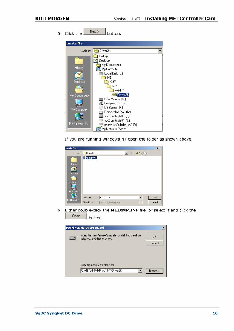
5. Click the button.
If you are running Windows NT open the folder as shown above.
6. Either double-click the MEIXMP.INF file, or select it and click the
button.
KOLLMORGEN Version 1 -11/07 Installing MEI Controller Card
SqDC SynqNet DC Drive 11
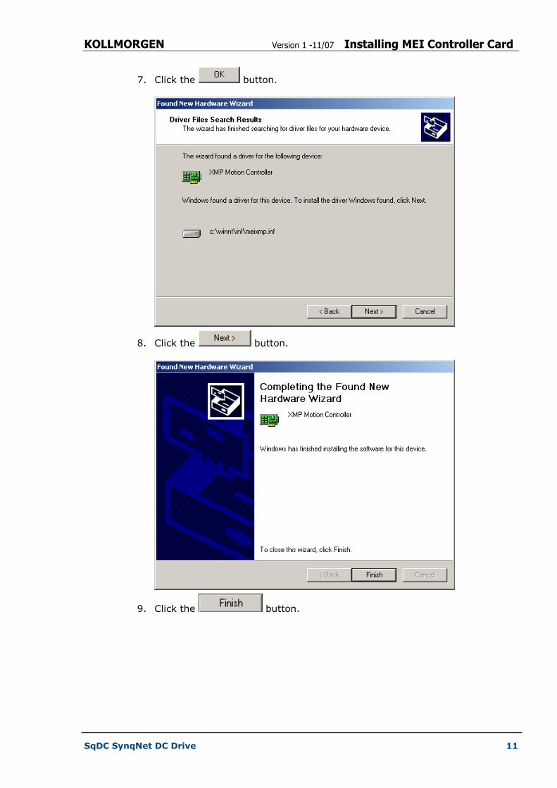
7. Click the button.
8. Click the button.
9. Click the button.
KOLLMORGEN Version 1 -11/07 Installing MEI Controller Card
SqDC SynqNet DC Drive 12
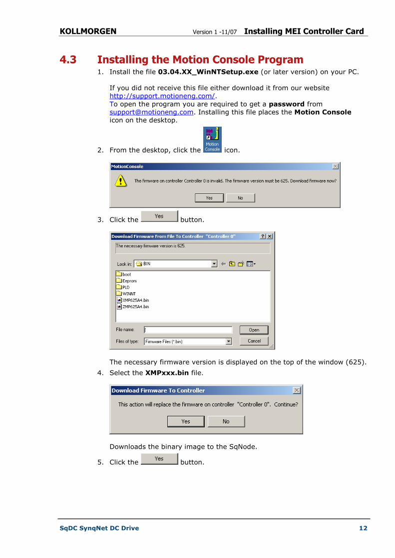
4.3 Installing the Motion Console Program 1. Install the file 03.04.XX_WinNTSetup.exe (or later version) on your PC.
If you did not receive this file either download it from our website
http://support.motioneng.com/.
To open the program you are required to get a password from
[email protected]. Installing this file places the Motion Console
icon on the desktop.
2. From the desktop, click the icon.
3. Click the button.
The necessary firmware version is displayed on the top of the window (625).
4. Select the XMPxxx.bin file.
Downloads the binary image to the SqNode.
5. Click the button.
KOLLMORGEN Version 1 -11/07 Using the Motion Console
SqDC SynqNet DC Drive 13
Chapter 5
5 USING THE MOTION CONSOLE
This section describes in a step-by-step format how to:
� Use the Motion Console to synchronize the SynqNet to the drive
� Configuring the motor parameters using a text editor
� Configuring the motion control console
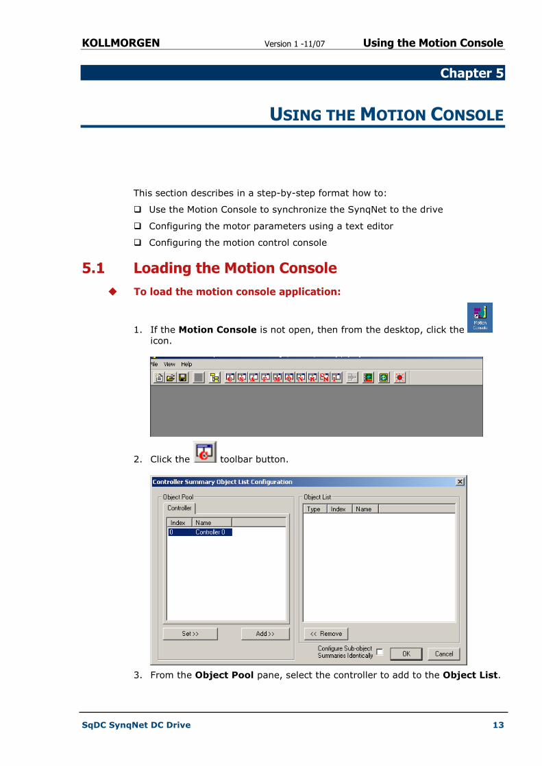
5.1 Loading the Motion Console
� To load the motion console application:
1. If the Motion Console is not open, then from the desktop, click the
icon.
2. Click the toolbar button.
3. From the Object Pool pane, select the controller to add to the Object List.

KOLLMORGEN Version 1 -11/07 Using the Motion Console
SqDC SynqNet DC Drive 14
4. Click the button.
5. Click the button.
6. Click the button to synchronize the controller and drive.
If the FPGA Runtime has not been previously installed the following message
is displayed.
KOLLMORGEN Version 1 -11/07 Using the Motion Console
SqDC SynqNet DC Drive 15
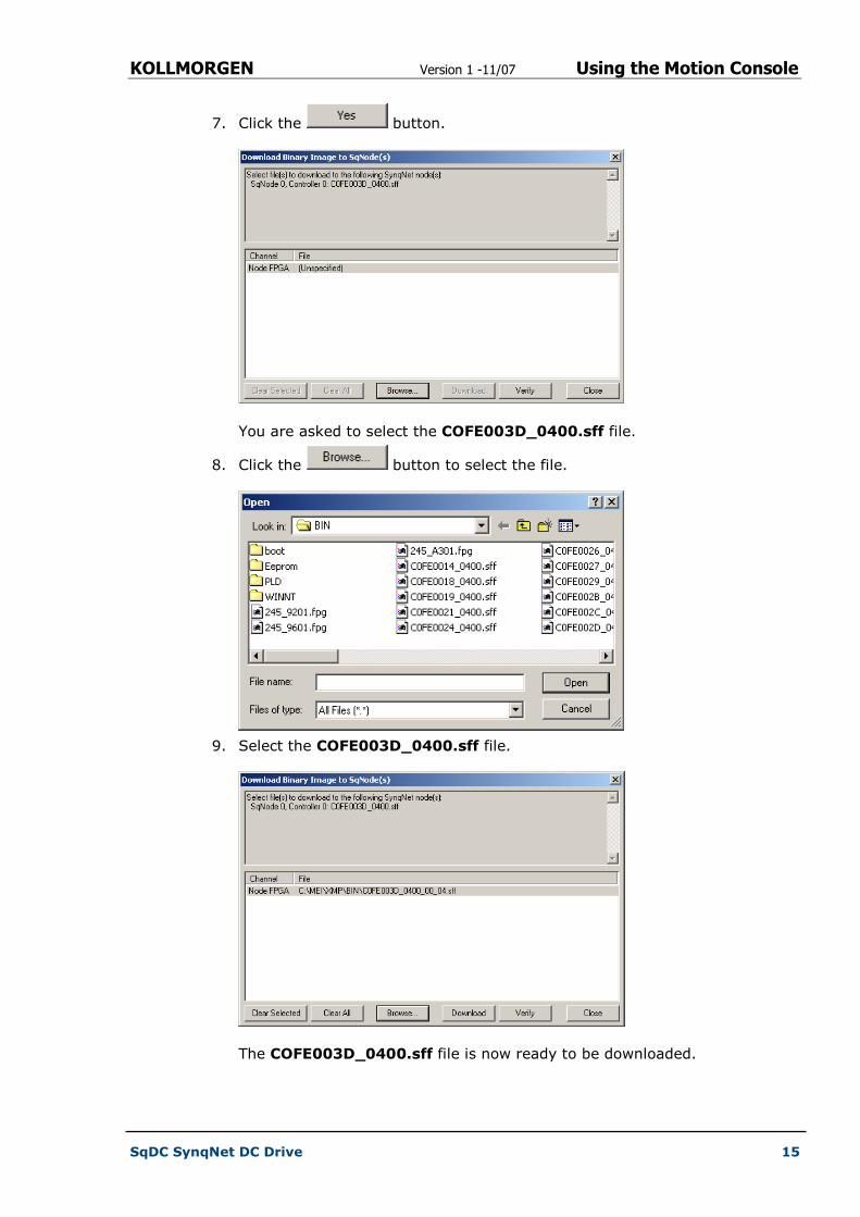
7. Click the button.
You are asked to select the COFE003D_0400.sff file.
8. Click the button to select the file.
9. Select the COFE003D_0400.sff file.
The COFE003D_0400.sff file is now ready to be downloaded.
KOLLMORGEN Version 1 -11/07 Using the Motion Console
SqDC SynqNet DC Drive 16
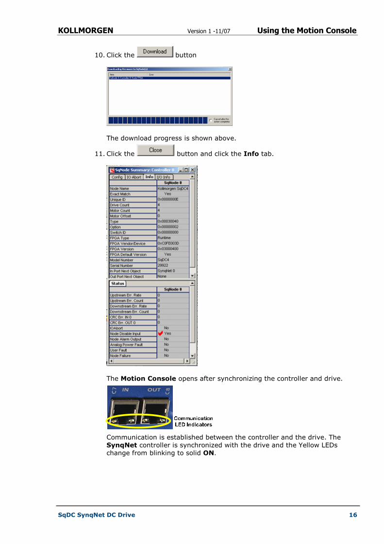
10. Click the button
The download progress is shown above.
11. Click the button and click the Info tab.
The Motion Console opens after synchronizing the controller and drive.
Communication is established between the controller and the drive. The
SynqNet controller is synchronized with the drive and the Yellow LEDs
change from blinking to solid ON.

KOLLMORGEN Version 1 -11/07 Using the Motion Console
SqDC SynqNet DC Drive 17
5.2 Configuring the Motor Parameters
NOTE
The motor parameters can only be uploaded once the SynqNet controller is
synchronized with the drive. See previous section.
This section explains how to upload the motor configuration parameters from
the motor drive controller using a Dos –get command to the PC and saved in
the Config.dc file. Once on the PC we can configure the parameters to suit the
specific motors you want to connect to the drive controller. When the file is
configured it is downloaded back onto the drive controller using a –set
command.
5.2.1 Uploading the Motor Parameters (get command)
� To upload the motor parameters from the drive unit:
1. At the command prompt, enter the following command:
sqDriveconfig –get config.dc –map kollmorgen sqDC.dm
This command fetches the parameters from the motor drive.
2. Press the ENTER key.
3. Enter Y and press the ENTER key, to the message,
Do you want to overwrite the existing file (y/n)?
The motor parameters for the four axes (0, 1, 2 and 3) are uploaded to
the PC.
KOLLMORGEN Version 1 -11/07 Using the Motion Console
SqDC SynqNet DC Drive 18
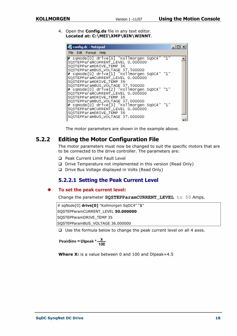
4. Open the Config.ds file in any text editor.
Located at: C:\MEI\XMP\BIN\WINNT.
The motor parameters are shown in the example above.
5.2.2 Editing the Motor Configuration File The motor parameters must now be changed to suit the specific motors that are
to be connected to the drive controller. The parameters are:
� Peak Current Limit Fault Level
� Drive Temperature not implemented in this version (Read Only)
� Drive Bus Voltage displayed in Volts (Read Only)
5.2.2.1 Setting the Peak Current Level
� To set the peak current level:
Change the parameter SQSTEPParamCURRENT_LEVEL to 50 Amps.
# sqNode[0] drive[0] "Kollmorgen SqDC4" "1"
SQSTEPParamCURRENT_LEVEL 50.000000
SQSTEPParamDRIVE_TEMP 35
SQSTEPParamBUS_VOLTAGE 36.000000
� Use the formula below to change the peak current level on all 4 axes.
Where X: is a value between 0 and 100 and Dlpeak=4.5
KOLLMORGEN Version 1 -11/07 Using the Motion Console
SqDC SynqNet DC Drive 19
5.2.3 Downloading the Motor Parameters (Set command)
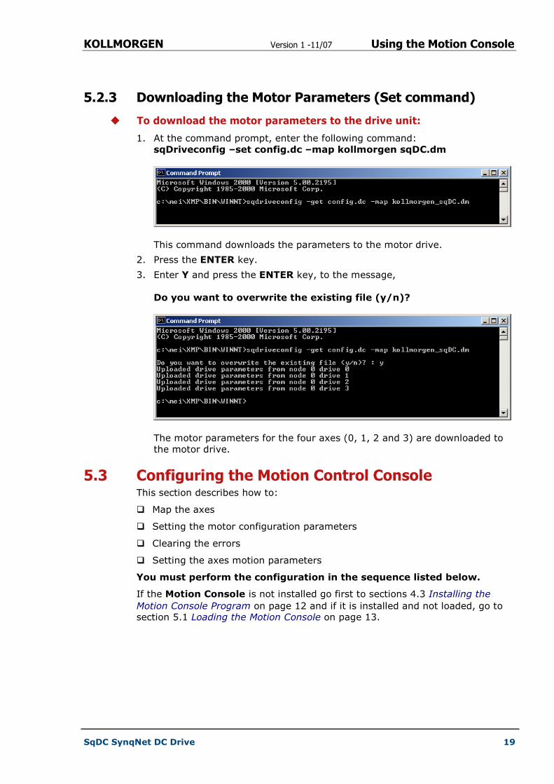
� To download the motor parameters to the drive unit:
1. At the command prompt, enter the following command:
sqDriveconfig –set config.dc –map kollmorgen sqDC.dm
This command downloads the parameters to the motor drive.
2. Press the ENTER key.
3. Enter Y and press the ENTER key, to the message,
Do you want to overwrite the existing file (y/n)?
The motor parameters for the four axes (0, 1, 2 and 3) are downloaded to
the motor drive.
5.3 Configuring the Motion Control Console This section describes how to:
� Map the axes
� Setting the motor configuration parameters
� Clearing the errors
� Setting the axes motion parameters
You must perform the configuration in the sequence listed below.
If the Motion Console is not installed go first to sections 4.3 Installing the
Motion Console Program on page 12 and if it is installed and not loaded, go to section 5.1 Loading the Motion Console on page 13.
KOLLMORGEN Version 1 -11/07 Using the Motion Console
SqDC SynqNet DC Drive 20
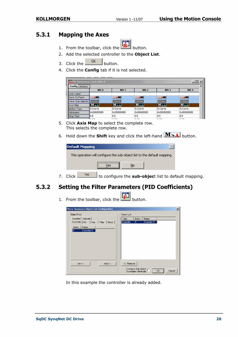
5.3.1 Mapping the Axes
1. From the toolbar, click the button.
2. Add the selected controller to the Object List.
3. Click the button.
4. Click the Config tab if it is not selected.
5. Click Axis Map to select the complete row.
This selects the complete row.
6. Hold down the Shift key and click the left-hand button.
7. Click to configure the sub-object list to default mapping.
5.3.2 Setting the Filter Parameters (PID Coefficients)
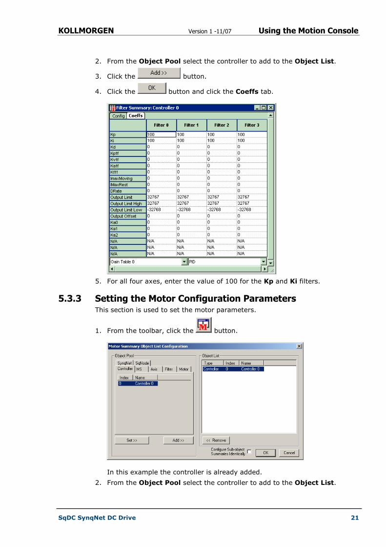
1. From the toolbar, click the button.
In this example the controller is already added.
KOLLMORGEN Version 1 -11/07 Using the Motion Console
SqDC SynqNet DC Drive 21
2. From the Object Pool select the controller to add to the Object List.
3. Click the button.
4. Click the button and click the Coeffs tab.
5. For all four axes, enter the value of 100 for the Kp and Ki filters.
5.3.3 Setting the Motor Configuration Parameters This section is used to set the motor parameters.
1. From the toolbar, click the button.
In this example the controller is already added.
2. From the Object Pool select the controller to add to the Object List.
KOLLMORGEN Version 1 -11/07 Using the Motion Console
SqDC SynqNet DC Drive 22
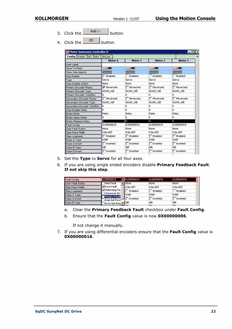
3. Click the button.
4. Click the button.
5. Set the Type to Servo for all four axes.
6. If you are using single ended encoders disable Primary Feedback Fault.
If not skip this step.
a. Clear the Primary Feedback Fault checkbox under Fault Config.
b. Ensure that the Fault Config value is now 0X00000006.
If not change it manually.
7. If you are using differential encoders ensure that the Fault Config value is
0X00000016.
KOLLMORGEN Version 1 -11/07 Using the Motion Console
SqDC SynqNet DC Drive 23
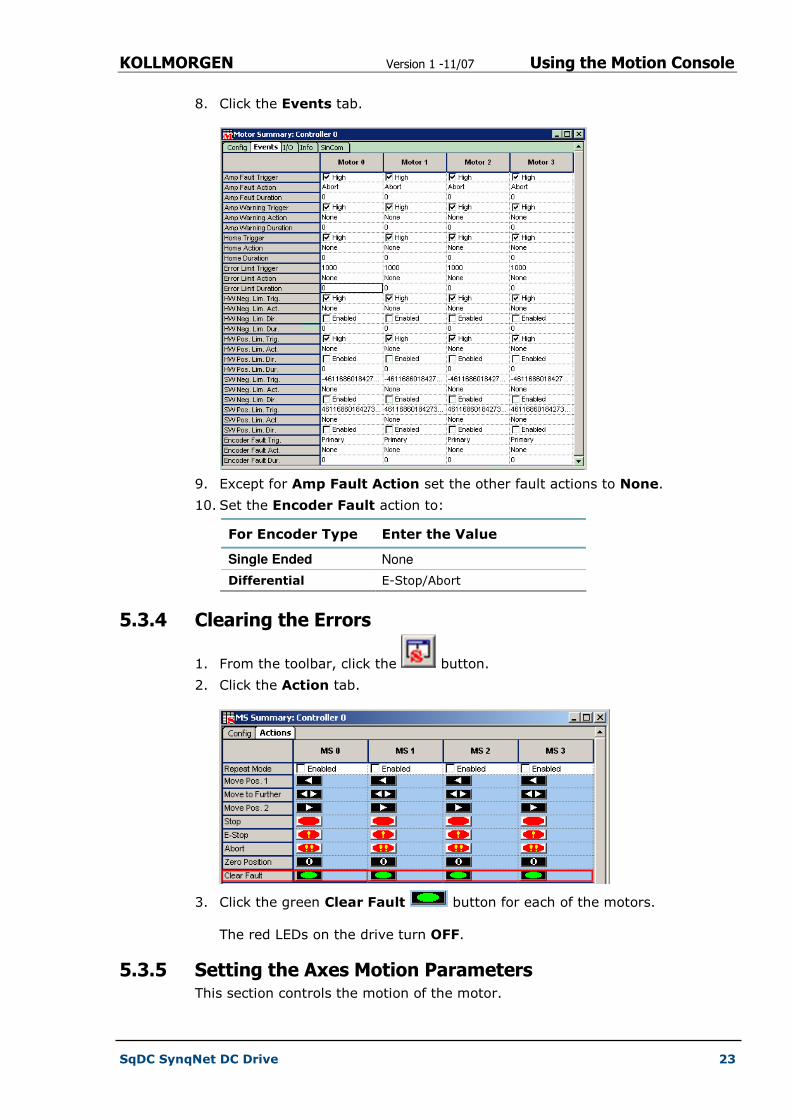
8. Click the Events tab.
9. Except for Amp Fault Action set the other fault actions to None.
10. Set the Encoder Fault action to:
For Encoder Type Enter the Value
Single Ended None
Differential E-Stop/Abort
5.3.4 Clearing the Errors
1. From the toolbar, click the button.
2. Click the Action tab.
3. Click the green Clear Fault button for each of the motors.
The red LEDs on the drive turn OFF.
5.3.5 Setting the Axes Motion Parameters This section controls the motion of the motor.

KOLLMORGEN Version 1 -11/07 Using the Motion Console
SqDC SynqNet DC Drive 24
1. From the toolbar, click the button.
2. Add the selected controller to the Object List.
3. Click the button.
4. Set the motion following parameters on each axis:
a. Position 1 and Position 2
b. Velocity
c. Acceleration
d. Deceleration
NOTE
All the other values are optional and can be set as required.
5.3.6 Set Amp Enable
1. From the toolbar, click the button.
2. Select the Amp Enabled checkbox (Enabled) for each motor.

KOLLMORGEN Version 1 -11/07 Using the Motion Console
SqDC SynqNet DC Drive 25
5.3.7 Start and Stop the Motors
1. From the toolbar, click the button.
2. Click the Actions tab.
3. Click Zero Position for all axes.
4. Click Clear Fault for all axes.
5. Select the Repeat Mode checkboxes (Enabled) for each motor.
6. Click to move the motor to position 1.
7. Click to move the motor to the furthest position.
8. Click to move the motor to position 2.
NOTE
Click the Abort button to force an error and then clear it by
clicking the Clear Fault button.

KOLLMORGEN Version 1 -11/07 Error Messages
SqDC SynqNet DC Drive 26
Chapter 6
6 ERROR MESSAGES
The sqDriveMsg Utility displays all the faults and warnings present on the
specified drive.
6.1 Using the sqDriveMsg Utility � Use Table 4 below as a guide to find the required faults and warnings.
Table 4 sqDriveMsg Utility Arguments
Argument Description
-? Help
-control # Controller number (default=0).
-server # Name or IP address of the host running server.exe.
-port # TCP/IP port on the host computer (default=3300).
-trace # Bit mask to specify trace information outputs.
-node # Node address of the SynqNet network (default=0).
-drive # Index of the drive relative to the node (default=0).
-motor # The MPI motor object mapped to the drive (default=0).
NOTE
You can use either –node and –drive, or just –motor to specify the desired
drive interface.
KOLLMORGEN Version 1 -11/07 Error Messages
SqDC SynqNet DC Drive 27
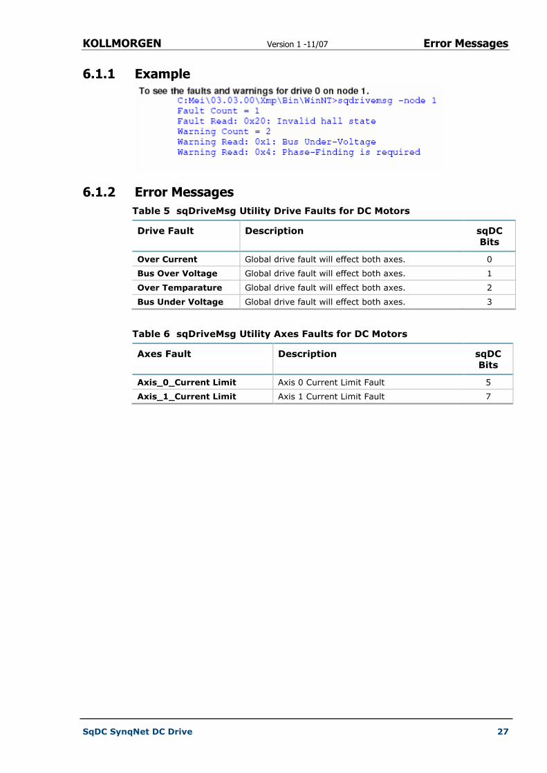
6.1.1 Example
6.1.2 Error Messages
Table 5 sqDriveMsg Utility Drive Faults for DC Motors
Drive Fault Description sqDC
Bits
Over Current Global drive fault will effect both axes. 0
Bus Over Voltage Global drive fault will effect both axes. 1
Over Temparature Global drive fault will effect both axes. 2
Bus Under Voltage Global drive fault will effect both axes. 3
Table 6 sqDriveMsg Utility Axes Faults for DC Motors
Axes Fault Description sqDC
Bits
Axis_0_Current Limit Axis 0 Current Limit Fault 5
Axis_1_Current Limit Axis 1 Current Limit Fault 7
KOLLMORGEN Version 1 -11/07 Hardware Specifications
SqDC SynqNet DC Drive 28
Appendix A HARDWARE SPECIFICATIONS
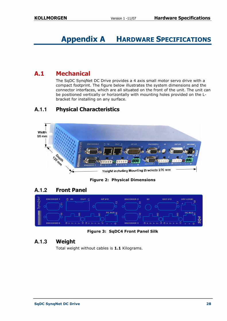
A.1 Mechanical The SqDC SynqNet DC Drive provides a 4 axis small motor servo drive with a
compact footprint. The figure below illustrates the system dimensions and the
connector interfaces, which are all situated on the front of the unit. The unit can
be positioned vertically or horizontally with mounting holes provided on the L-
bracket for installing on any surface.
A.1.1 Physical Characteristics
Depth
120 mm
Figure 2: Physical Dimensions
A.1.2 Front Panel
Figure 3: SqDC4 Front Panel Silk
A.1.3 Weight Total weight without cables is 1.1 Kilograms.
KOLLMORGEN Version 1 -11/07 Configuration File Parameters
SqDC SynqNet DC Drive 29
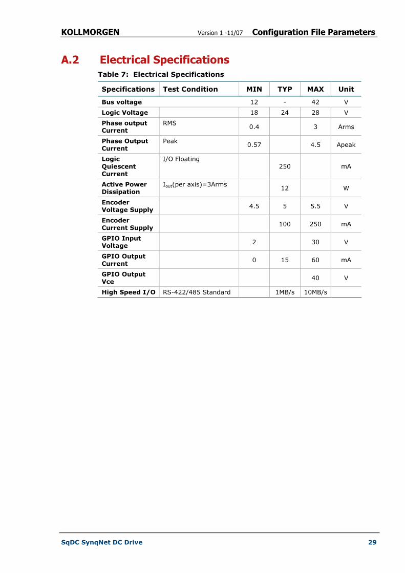
A.2 Electrical Specifications
Table 7: Electrical Specifications
Specifications Test Condition MIN TYP MAX Unit
Bus voltage 12 - 42 V
Logic Voltage 18 24 28 V
Phase output Current
RMS 0.4 3 Arms
Phase Output Current
Peak 0.57 4.5 Apeak
Logic
Quiescent Current
I/O Floating
250 mA
Active Power Dissipation
Iout(per axis)=3Arms 12 W
Encoder Voltage Supply
4.5 5 5.5 V
Encoder Current Supply
100 250 mA
GPIO Input Voltage
2 30 V
GPIO Output Current
0 15 60 mA
GPIO Output Vce
40 V
High Speed I/O RS-422/485 Standard 1MB/s 10MB/s

KOLLMORGEN Version 1 -11/07 Configuration File Parameters
SqDC SynqNet DC Drive 30
A.3 Environmental Specifications
Table 8: Environmental Specifications
Specifications Description
Ambient Temperature 0 to +50 Degrees C
Storage Temperature -20 to 70 Degrees C
Maximum L-Bracket Temperature
70 Degree C
Current per axis without additional heat-sinking
~1.5 Arms
Ambient Humidity 10% to 90%, non condensing
Atmosphere Without corrosive gasses or dust
Altitude De-rated 5% per 1000ft (300m) above 3300ft (1000m)
Vibration 0.5 G
DANGER
Additional cooling may be required to limit the plate temperature to 70°C
when operating the unit at higher currents across multiple axes.
IMPORTANT NOTE
This does not limit the peak transient current limit of 5A per axis only the
continuous rated value.

KOLLMORGEN Version 1 -11/07 Configuration File Parameters
SqDC SynqNet DC Drive 31
Chapter 7
Appendix B CONFIGURATION FILE PARAMETERS
The motor parameters must now be changed to suit the specific motors that are
to be connected to the drive controller. The parameters are:
� Peak Current Level
� Drive Temperature (Read Only)
� Drive Bus Voltage displayed in Volts (Read Only)
# sqNode[0] drive[0] "Kollmorgen SqDC4" "1"
SQSTEPParamCURRENT_LEVEL 0.000000
SQSTEPParamDRIVE_TEMP 36
SQSTEPParamBUS_VOLTAGE 37.500000
# sqNode[0] drive[1] "Kollmorgen SqDC4" "1"
SQSTEPParamCURRENT_LEVEL 0.000000
SQSTEPParamDRIVE_TEMP 36
SQSTEPParamBUS_VOLTAGE 37.500000
# sqNode[0] drive[2] "Kollmorgen SqDC4" "1"
SQSTEPParamCURRENT_LEVEL 0.000000
SQSTEPParamDRIVE_TEMP 36
SQSTEPParamBUS_VOLTAGE 37.000000
# sqNode[0] drive[3] "Kollmorgen SqDC4" "1"
SQSTEPParamCURRENT_LEVEL 0.000000
SQSTEPParamDRIVE_TEMP 36
SQSTEPParamBUS_VOLTAGE 37.000000
B.1 Peak Current Level Amplitude of the sine wave produced as a percentage of the drive peak rated
current which is 4.5 Amps.
Where X: is a value between 0 and 100 and Dlpeak=4.5

KOLLMORGEN Version 1 -11/07 Configuration File Parameters
SqDC SynqNet DC Drive 32
B.2 Heat-sink Temperature This parameter is READ-ONLY and provides the temperature of the heatsink in
degrees Celsius.
� Valid operating range from 10-80°C (50-176°F)
� Accuracy of reading ±3%
NOTE
The over-temperature fault is set at 70°C (158°F).
B.3 Bus Voltage This parameter is READ-ONLY and provides the voltage of the DC bus in volts.
� Valid measuring range from 0-96 Volts
� Accuracy of reading ±1%
NOTE
The over-voltage fault is set at 48 Volts (DC).

KOLLMORGEN Version 1 -11/07 Encoders
SqDC SynqNet DC Drive 33
Appendix C ENCODERS
Two encoder options are available for use with the SqDC:
� Incremental (ABI) Encoder
� Absolute SSI based Encoder
C.1 Incremental Encoders The SynqNet system can accommodate incremental encoders with and without
the the Index pulse use for absolute position definition. They can be supplied in
either single ended or differential wiring configuration. Single ended wiring is
generally cheaper than the differential output types but is more susceptible to
electrical noise and provides no wire break indication.
C.1.1 Single Ended ABI Encoders Single ended encoders have only one wire per output. They could have four or
five wires. Two supply power and then there is A, B and I (index).
Advantages
� Simple to build and inexpensive
Disadvantages
� No line break fault detection
� Susceptible to noise
� Does not keep position information after power off
DB-9 Wiring Diagram

KOLLMORGEN Version 1 -11/07 Connector Pin-Outs
SqDC SynqNet DC Drive 34
C.1.2 Differential ABI Encoders
Advantages
� More noise immunity
� Provides wire break indication
Disadvantages
� Does not keep position after loss of power
DB-9 Wiring Diagram
C.2 Absolute Encoders An absolute encoder provides a unique value at each position and retains actual
shaft position even if power fails. The electronic interface SSI or Synchronous
Serial Interface was designed for use with absolute encoders and is a digital
communication protocol.
DB-9 Wiring Diagram
KOLLMORGEN Version 1 -11/07 Connector Pin-Outs
SqDC SynqNet DC Drive 35
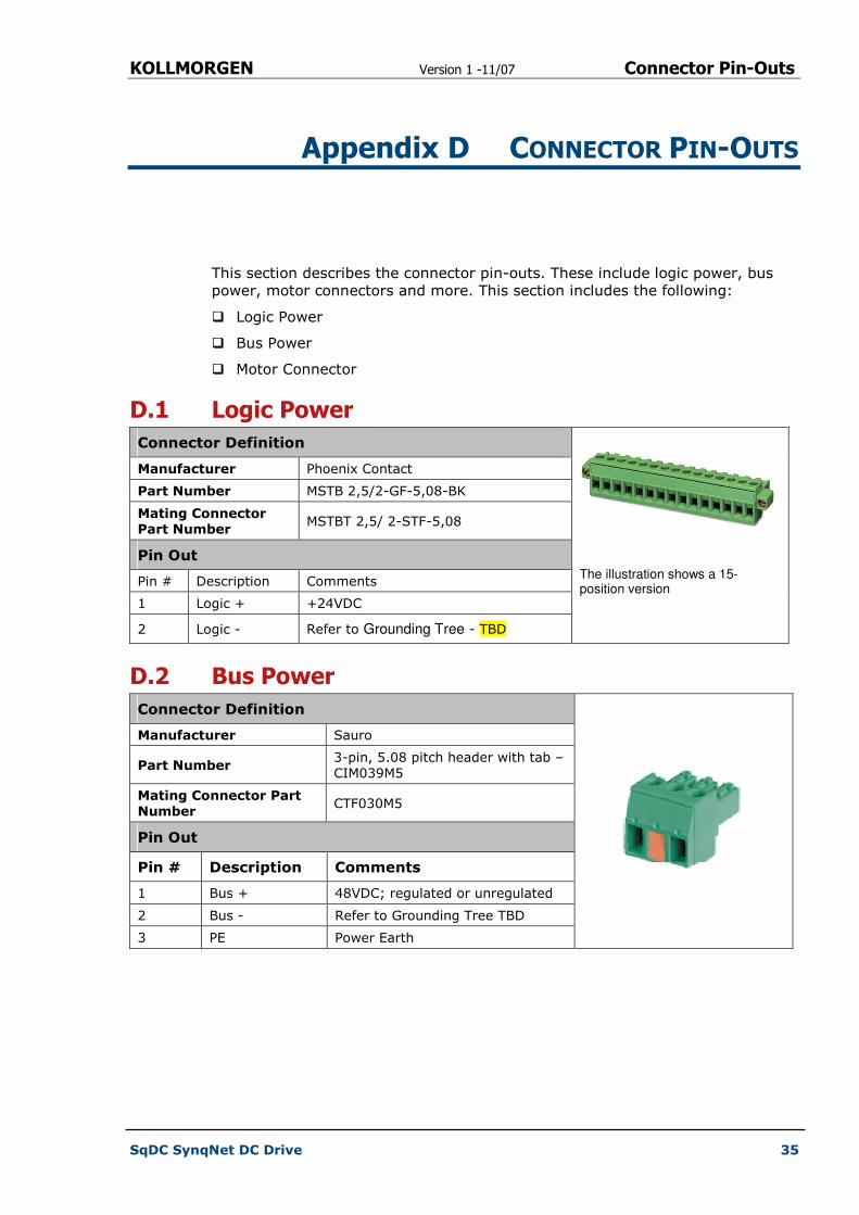
Appendix D CONNECTOR PIN-OUTS
This section describes the connector pin-outs. These include logic power, bus
power, motor connectors and more. This section includes the following:
� Logic Power
� Bus Power
� Motor Connector
D.1 Logic Power
Connector Definition
Manufacturer Phoenix Contact
Part Number MSTB 2,5/2-GF-5,08-BK
Mating Connector Part Number
MSTBT 2,5/ 2-STF-5,08
Pin Out
Pin # Description Comments
1 Logic + +24VDC
2 Logic - Refer to Grounding Tree - TBD
The illustration shows a 15-position version
D.2 Bus Power
Connector Definition
Manufacturer Sauro
Part Number 3-pin, 5.08 pitch header with tab –
CIM039M5
Mating Connector Part Number
CTF030M5
Pin Out
Pin # Description Comments
1 Bus + 48VDC; regulated or unregulated
2 Bus - Refer to Grounding Tree TBD
3 PE Power Earth

KOLLMORGEN Version 1 -11/07 Connector Pin-Outs
SqDC SynqNet DC Drive 36
D.3 Motor Connector
Connector Definition
Manufacturer Molex
Part Number 39-30-3056; 4.20mm (.165")
Pitch Mini-Fit Jr.™ Header
Mating Connector Part Number
39-01-4051 (Housing) 44476-
3112 (Pins)
Pin Out
Pin # Description Comments
1 Phase A-
2 Phase A+
3 Phase B+
4 Phase B-
5 PE Power Earth
D.4 Encoder Connector
Connector Definition
Manufacturer Stewart
Part Number D-Type 9 pins Female
Mating Connector Part Number
Pin Out
Pin # Differential ABI
Single Ended ABI
Differential SSI
1 A+ A ENC_5V
2 B+ B CLK+
3 I+ I DATA+
4 ENC_GND (SE_CON)
ENC_5V (SE_CON)
ENC_GND (SE_CON)
5 ENC_GND ENC_GND ENC_GND
6 A- NC ENC_GND
7 B- NC CLK-
8 I- NC DATA-
9 ENC_5V ENC_5V ENC_5V

KOLLMORGEN Version 1 -11/07 Sales and Services
SqDC SynqNet DC Drive 37
Appendix E SALES AND SERVICES
We are committed to quality customer service. In order to serve in the most
effective way, please contact your local sales representative for assistance.
If you are unaware of your local sales representative, please contact us.
Europe
Danaher Motion Customer Support Europe
E-mail: [email protected]
Phone: +972-3-927-3800
Fax: +972-3-922-8075
www.danahermotion.net
North America
Danaher Motion Customer Support North America
E-mail: [email protected]
Phone: +972-3-927-3800
Fax: +972-3-927-8075
www.danahermotion.com