spudcan-soil-jacket pile group foundation interaction ...jack-up platform, spudcan, jacket platform,...
TRANSCRIPT
1/12
14 International Jack-up Conference 2013
Spudcan-Soil-Jacket Pile Group Foundation Interaction
During Jack-Up Rig Installation and Removal
L. Kellezi & S. Sundararajan GEO - Danish Geotechnical Institute
Maglebjergvej 1, DK 2800 Copenhagen, Denmark
Abstract
For a three-legged jack-up platform located at an oil field in the North Sea, assessment of spudcan-soil-pile
group interaction during the rig installations and pullout / extraction at the vicinity of a jacket platform, is
carried out. After several attempts and considering the rig operation flexibility, the distance from the nearest
spudcans to the nearest jacket mudmat and pile group foundations is determined. The soil conditions at the
site consist of soft-to-stiff clay underlain by dense sand and firm to stiff clay. Conventional spudcan
penetration analysis is carried out first in order to predict the maximum spudcan penetrations to be expected
during the rig installation. Based on the results for lower bound soil strength, finite element (FE) modelling
of the spudcan-soil-pile group interaction is carried out with Plaxis programs. Two methods are applied to
get a clear insight on the impact the rig installation and pullout / extraction at different clearances, will have
on the jacket foundation:
1. Modelling of the spudcan penetration to the conventionally predicted depth, is carried out in an
axisymmetric two-dimensional (2D) FE analysis in order to estimate the soil movement at the
vicinity of the nearest pile group.
2. A three-dimensional (3D) FE modelling of the spudcan-soil-pile group interaction is carried out in
order to estimate the soil movement and the impact the additional soil pressure has on the piles of the
group, in terms of deformation, additional bending moment and shear force developed.
The FE modelling for the final jack-up location relative to the jacket shows the piles to be out of the critical
rupture figure developed in the clay during spudcan penetration / extraction. General conclusions useful to
practitioners dealing with such engineering applications are drawn.
Keywords Jack-up platform, spudcan, jacket platform, pile group, mudmat, conventional analysis, finite element (FE)
analysis, failure mechanism, bending moment, shear force
Introduction Oil jack-up rigs are generally used to perform drilling operations near to an existing jacket platform in
shallow water. In several locations, depending on the soil conditions, a large volume of the soil is displaced
laterally and vertically, inducing consequently severe stresses on adjacent piles supporting the jacket
platform, during spudcan installation [1], [2], [3], and extraction processes. The previous studies show that
the induced loading on the pile decreases with increasing clearance between the spudcan and the pile.
However, in the previous investigations only monopiles jacket are investigated and only during the rig
installation.
2/12
14 International Jack-up Conference 2013
Assessment of spudcan-soil-pile group foundation interaction during installation and extraction of a three-
legged jack-up rig at the vicinity of a jacket platform in the North Sea is presented in this paper. After
investigation of different clearances and based on the flexibility of the operation, the jack-up rig is finally
located at a position corresponding to a well sufficient distance from the spudcan edge, to the edge of the
nearest mudmat / pile group. The current assessment is focused on quantifying the impact the installation and
extraction of the rig, at the south-southeast of the jacket platform, have even at a considerable clearance
corresponding to one or more than two spudcan diameters.
Spudcan penetration prediction for the installation of the jack-up rig at this location is first carried out based
on [4] and [5]. After that, the assessment is mainly based on the FE modelling, [6] and [7], of the spudcan
penetration [8], [9] with the focus on the soil displacement at the vicinity of the pile group. 2D and 3D FE
analyses are carried out for comparison using the advantages with regard to fine mesh and model size,
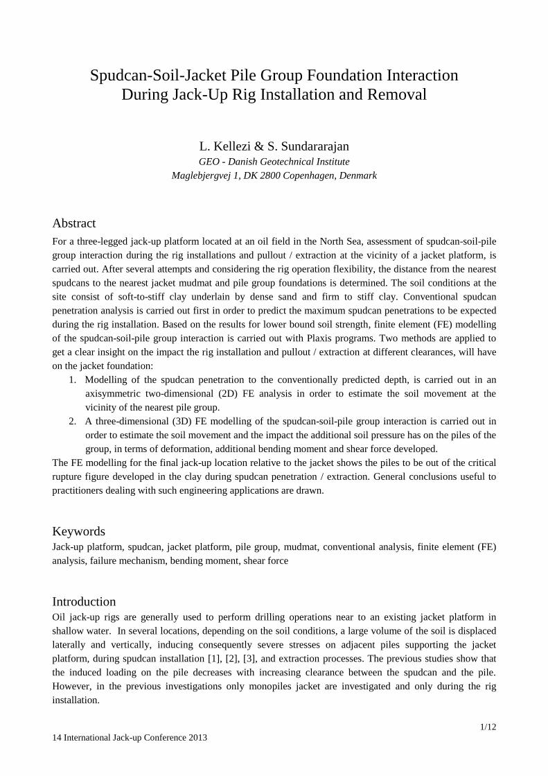
Jack-up Rig and Jacket Platform Relative Positions The location plan with the investigated positions of the jack-up rig relative to the jacket platform, or the
mudmat / spudcan layouts, which are the focus of the current assessment, is given in Figure 1a. Considering
the nearest spudcan to the jacket platform, the Starboard Leg spudcan is at the considered positions about
one and two spudcan diameters from the closest platform pile group at the mudline.
Figure 1 a-Jack-up mudmat / spudcan layout; b-the nearest borehole / CPT locations;
Spudcan Geometry and Loads The jack-up rig spudcans have an equivalent diameter of 18.13 m and a full contact area of 255.4 m
2.
Distance from the spudcan base (full contact) to the spudcan tip is 1.8 m. The total spudcan height is 5.5 m
and the spudcan volume is 727 m3. The maximum preload is about 13600 tons / leg.
Pile and Pile Group Geometry The outer diameter of the piles in the group is 2.44 m and the thickness of the pile wall is 0.075 m. The
jacket foundation design is performed in accordance with American Petroleum Institute (API) guidelines.
a b
Spudcan edge-to-pile
edge distance=16 m
Spudcan edge-to-pile
edge distance=36 m
3/12
14 International Jack-up Conference 2013
Design of the platform piles are based on interactive jacket-foundation analyses with soil-nonlinearity and
pile group interaction effect included. Due to penetration depth during pile driving, 3 piles per leg to
maximum penetration of 62 m was adopted for the design. The in-place utilization of the piles is rather
modest (piles are designed with Type IV steel of yield stress Fy = 325 N/mm2
= 325 MPa). Beam-column
analyses were performed to calculate lateral pile capacity. The plots of bending stresses versus depth below
pile head indicate a maximum bending stress of 150 MPa and maximum in-place utilization 0.76.
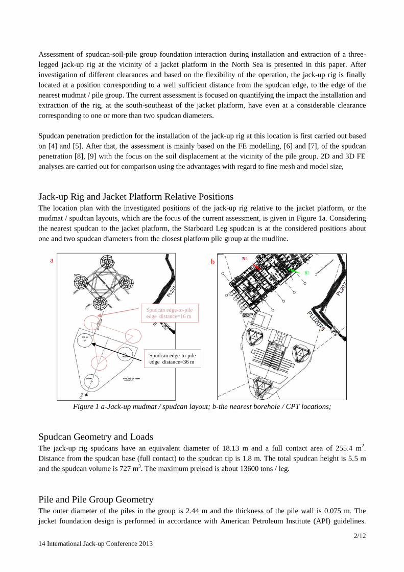
Available Soil Data and Interpreted Soil Conditions The proposed position of the jack-up rig with heading 200°, is plotted along with the available geotechnical
boreholes / cone penetration test (CPTs) B1 and B2 at the vicinity in Figure 1b. Engineering assessment for a
sister jack-up rig at a nearby location at the same field complex, is previously carried out. The current
borehole logs suggest that the soil conditions at the site are possibly uniform in terms of the thickness of soil
layers. However, there are differences with respect to the undrained shear strength for the clay layers.
Figure 2, The nearest borehole / CPT Log, B1
No boreholes / CPTs are available at the spudcan locations for the current rig positions. The closest available
deep boreholes / CPT’s to the Starboard Leg are carried out 42 m and 90 m below seabed. The approximate
distance of these boreholes / CPTs from this spudcan are 70 m and 80 m, respectively. The log for the closest
borehole B1 is given in Figure 2. This borehole indicates that the soil conditions consist of about 14.6 m of
soft-to-stiff clay, underlain by a layer of dense sand to (14.6 - 16.5) m depth. Below this sand firm to stiff
clay is found to depths (16.5 - 25.1) m below seabed, overlying further down dense sand.

4/12
14 International Jack-up Conference 2013
To author’s knowledge, the previous installations at the site have confirmed that the spudcans of this type of
rig, penetrate (after experiencing some rapid penetrations during a safe installation procedure) to depths of
about (15-17) m below seabed, resting on top of the sand layer found at these depths. However, in the
previous assessments, except the critical conditions in the upper part of the soil profile, the risk for punch
through from (15-17) m to (24-26) m below seabed, was also investigated. The capacity to punch through at
these depths is very much dependent on the thickness of the sand layer and the strength and thickness of the
underlying clay, which are unknown at the current rig location. Considering previous assessments and
installation feedbacks, which did not confirm any punch through at deeper soil, the current assessment is
mainly based on the soil data given in borehole / CPT B1.
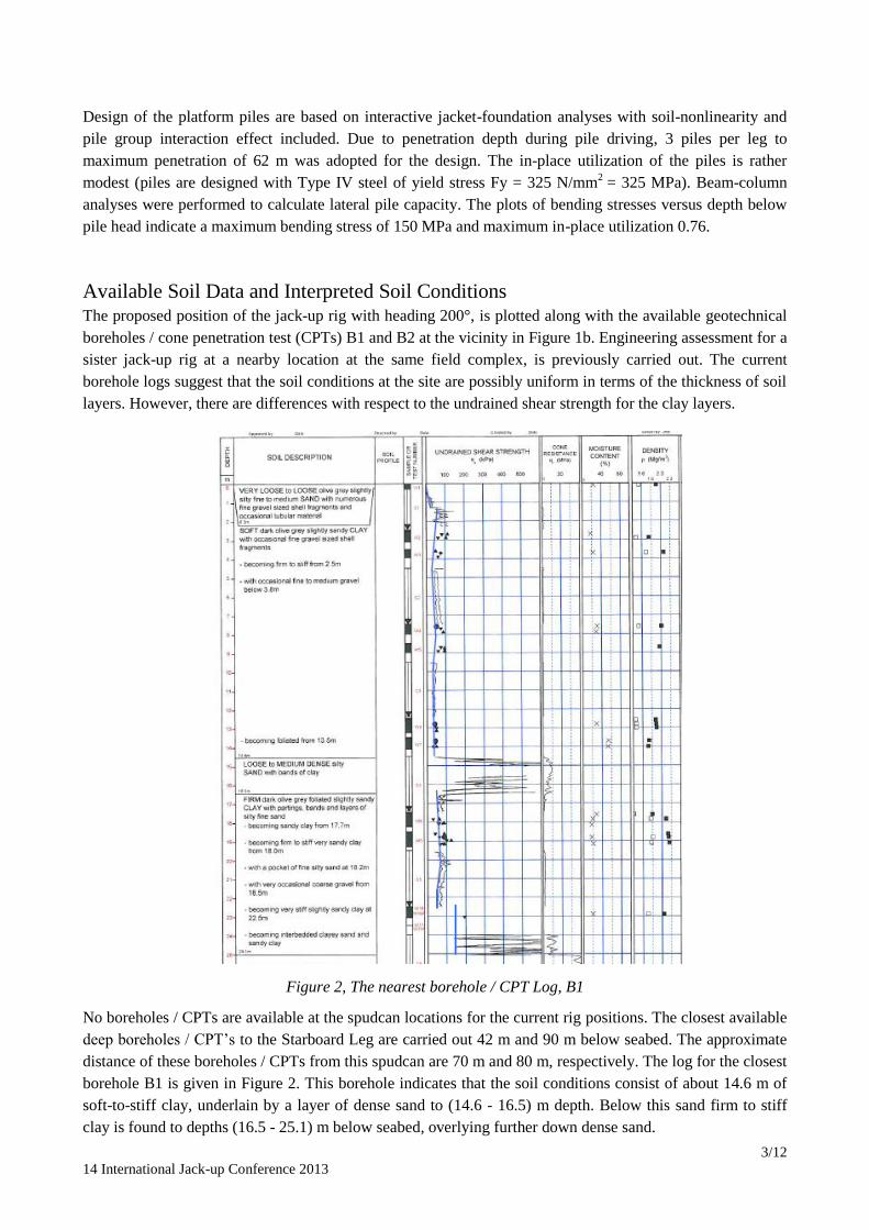
Predicted Spudcan Penetration Spudcan penetration analyses have been performed for the rig using the inferred soil profile from the nearest
geotechnical borehole B1. The penetration analyses given in Figure 3 indicate that spudcan penetrations
maximum to 15.8 m can be measured for a preload footing reaction of 13600 tons / leg. Rapid spudcan
penetrations / punch through are predicted to occur during preloading, consequently, a cautious approach to
installation of the unit is recommended, meaning preloading on a leg-by-leg basis. Some measurements from
the sister rigs at other jack-up locations at the field are plotted in Figure 3 in order to give an idea on the
vertical bearing capacity at the site.
Jack-Up Installation and Spudcan-Soil – Pile Group Interaction According to [4], for jack-ups located in close proximity of pile-founded platforms, soil displacement caused
by the spudcan penetration will induce lateral loading into the nearby piles. The amount of the soil
displacement will depend on the spudcan proximity (spudcan edge-to-pile distance), the spudcan diameter
and the spudcan penetration. If the foundation materials comprise either a deep layer of homogeneous firm to
stiff clay or sand and if the proximity of the spudcan to the pile is greater than one spudcan diameter, then no
significant pile loading is expected.
However, the recommendation in [4] is general and does, not specify on the dependence on the amount of
the spudcan penetrations (penetrations down to approximately 16 m as predicted for the rig at the current
location), effect of a floating or socket pile, effect of the upper clay thickness for a socket pile, effect of the
clay rigidity index (stiffness over strength ratio), effect of pile rigidity or pile bending stiffness, the spudcan-
pile group interaction etc.
Based on the above, although the current spudcan-pile group clearances are one and more than two spudcan
diameters, there are still additional loads developed on the pile. If they are estimated to be critical or not, this
depend on the design safety the pile group foundations. In order to quantify the impact the jack-up
installation will have on the jacket platform piles; assessment of the spudcan-pile group interaction is carried
out as described in the following sections. The calculation methods are applicable to any clearance imposed
at the site. The results will of course be different, being more critical for decreasing clearance. There are
different ways how to determine the magnitude and the extent of the soil movement around the spudcan and
the nearby effected zone, at the proximity of the jacket piles. Two different methods, both based on the FE
analyses are described below: Characteristic lower bound soil parameters are applied..
5/12
14 International Jack-up Conference 2013
Figure 3, Conventional spudcan penetration predictions and site measurements
2D Axisymmetric FE Analysis
The purpose of carrying out 2D axisymmetric FE modelling is to assess the amount of the soil displacement
at the vicinity of the pile foundation, while the spudcan penetrates to the predicted depth. FE modelling of
the spudcan penetration is carried out with Plaxis FE software [6]. Such modelling with FE programs like
Plaxis, Abaqus, Elfen etc. have been carried out by the authors and a series of papers can be found at
http://www.geo.dk/articles.aspx. Due to the multi-layered soil profile and Plaxis program limitations, the
following assumptions / simplifications are made in building the FE models:
• Axisymmetric modelling of the spudcan-soil-pile group interaction is carried out.
• The axisymmetric model size is determined from the aimed spudcan-pile foundation clearance and
the lateral boundary effect on the soil behavior at the vicinity of the pile foundation.
• Sand is modelled in drained conditions using Mohr-Coulomb constitutive model.
• Clay is modelled in undrained conditions using Mohr Coulomb or Tresca soil model.
• The initial geostatic conditions are calculated first. In line with the spudcan conventional penetration
analyses, FE analyses utilize effective unit weights for the seabed soil layers, keeping the water table
at the bottom of the FE model.
• Mesh has been generated using 15-noded triangular finite elements,
• The spudcan is modelled as a weightless elastic (drained) body.
6/12
14 International Jack-up Conference 2013
• The deformation parameters (E moduli) for sand are derived based on the CPT data and on undrained
shear strength for clays (E=500*cu).
• Vertical displacement is applied at the full base of the spudcan and the reaction force (not very
important in this case) is computed and recorded. The achievement of the large spudcan penetration
during the analysis is the most important in the current modelling.
• Updated Mesh (UM) analyses are carried out in order to take into account the large deformations.
• Soil backflow is not / cannot be modelled. However, due to the aimed spudcan-pile group clearance,
backflow is not expected to have a major impact on the additional forces on the pile foundation.
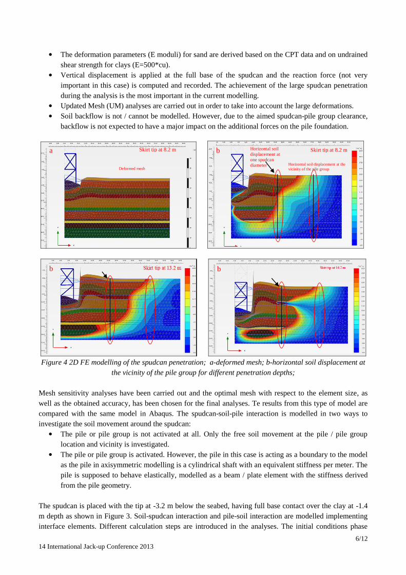
Figure 4 2D FE modelling of the spudcan penetration; a-deformed mesh; b-horizontal soil displacement at
the vicinity of the pile group for different penetration depths;
Mesh sensitivity analyses have been carried out and the optimal mesh with respect to the element size, as
well as the obtained accuracy, has been chosen for the final analyses. Te results from this type of model are
compared with the same model in Abaqus. The spudcan-soil-pile interaction is modelled in two ways to
investigate the soil movement around the spudcan:
• The pile or pile group is not activated at all. Only the free soil movement at the pile / pile group
location and vicinity is investigated.
• The pile or pile group is activated. However, the pile in this case is acting as a boundary to the model
as the pile in axisymmetric modelling is a cylindrical shaft with an equivalent stiffness per meter. The
pile is supposed to behave elastically, modelled as a beam / plate element with the stiffness derived
from the pile geometry.
The spudcan is placed with the tip at -3.2 m below the seabed, having full base contact over the clay at -1.4
m depth as shown in Figure 3. Soil-spudcan interaction and pile-soil interaction are modelled implementing
interface elements. Different calculation steps are introduced in the analyses. The initial conditions phase
Deformed mesh Horizontal soil displacement at the
vicinity of the pile group
Skirt tip at 8.2 m Skirt tip at 8.2 m
b b
a b Horizontal soil
displacement at
one spudcan
diameter

7/12
14 International Jack-up Conference 2013
consists of the undisturbed soil. After that the spudcan is installed and the penetration initiated with and
without having the pile activated. The penetration is applied in different steps with 5 m penetration step. The
results are for the axisymmetric analyses, without pile activation, given in Figure 4 and Figure 5. For a very
small clearance, equal to 6 m, the lateral soil movement is (3.0-3.5) m, for 16 m (one spudcan diameter)
more than 0.4 m, and for 36 m, (more than 2 spudcan diameters), (5-20) mm..
a – Lateral soil movement at the 6 m b – Vertical soil movement at the 6 m
c – Lateral soil movement at the 16 m d –Vertical soil movement at the 16 m
e –Lateral soil movement at the 36 m f –Vertical soil movement at the 36 m
Figure 5.(a, b, c, d, e, f) 2D FE lateral and vertical soil movements during full spudcan penetration at
distance from the spudcan edge 6 m, 16 m & 36 m
3D FE Modelling
3D FE modelling of the spudcan-soil-pile group interaction is carried out in order to estimate the amount of
soil movements at the proximity of the pile group, the displacements / deformations of the piles in the group

8/12
14 International Jack-up Conference 2013
and the additional forces induced on the piles due to the spudcan installation. Considering the program
limitations, similar assumptions / simplifications as in 2D axisymmetric analyses are made in building the
3D FE model in Plaxis 3D Foundation [7]. In addition, 3D mesh has been generated using triangular prism
elements of the second order (15-noded).
Different from the axisymmetric analyses, the 3D analysis is force-driven in such a way that a load equal to
the expected preload is applied on the in-placed spudcan (with full base contact at the same depth as in the
axisymmetric analyses) and the penetration recorded.
Figure 6 3D FE modelling of the spudcan-soil-pile group interaction during spudcan installation (clearance
=one spudcan diameter); a-the 3D FE model; b-the total soil displacements; c-the horizontal soil
displacements in z-directions at -1.4 depth; d- the horizontal pile displacements in z-direction;
At first, mesh sensitivity analyses have been carried comparing the results (for the scenario without pile / pile
group) with the axisymmetric model. The optimal 3D mesh with respect to model size and the obtained
accuracy, has been then chosen. Plastic analyses (small strain theory) are carried out, since no UM is
available in the applied 3D Plaxis program. The three piles (just like the single pile in the axisymmetric
model) are modelled as vertical and continuing to the bottom model boundary (30 m below seabed), where
competent soil conditions are expected based on the borehole / CPT B1. Below this depth (considered as
infinite socket depth), the piles are expected not to be effected from the spudcan penetrations.
In addition, at the top of the piles the mudmat is installed extended to the lateral boundary of the model,
restricting horizontal movement due to pile foundation-jacket structure interaction effect. This creates a more
or less realistic connection of the piles and the structure, not a typical fixed headed pile generally considered
c
b a
d
9/12
14 International Jack-up Conference 2013
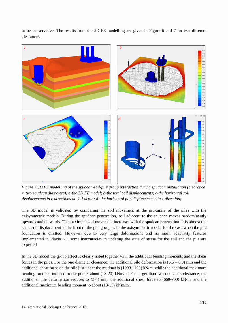
to be conservative. The results from the 3D FE modelling are given in Figure 6 and 7 for two different
clearances.
Figure 7 3D FE modelling of the spudcan-soil-pile group interaction during spudcan installation (clearance
> two spudcan diameters); a-the 3D FE model; b-the total soil displacements; c-the horizontal soil
displacements in z-directions at -1.4 depth; d- the horizontal pile displacements in z-direction;
The 3D model is validated by comparing the soil movement at the proximity of the piles with the
axisymmetric models. During the spudcan penetration, soil adjacent to the spudcan moves predominantly
upwards and outwards. The maximum soil movement increases with the spudcan penetration. It is almost the
same soil displacement in the front of the pile group as in the axisymmetric model for the case when the pile
foundation is omitted. However, due to very large deformations and no mesh adaptivity features
implemented in Plaxis 3D, some inaccuracies in updating the state of stress for the soil and the pile are
expected.
In the 3D model the group effect is clearly noted together with the additional bending moments and the shear
forces in the piles. For the one diameter clearance, the additional pile deformation is (5.5 – 6.0) mm and the
additional shear force on the pile just under the mudmat is (1000-1100) kN/m, while the additional maximum
bending moment induced in the pile is about (18-20) kNm/m. For larger than two diameters clearance, the
additional pile deformation reduces to (3-4) mm, the additional shear force to (660-700) kN/m, and the
additional maximum bending moment to about (13-15) kNm/m..
c d
a b
10/12
14 International Jack-up Conference 2013
Jack-Up Extraction and Spudcan-Soil – Pile Group Interaction No guidelines are given in [4] with regard to spudcan-pile interaction during leg extraction. Based on the
same reasons as described above, extraction analyses are carried out in the following in order to quantify the
impact the pullout of the Starboard Leg spudcan will have on the nearest platform pile foundation. There are
different ways how to determine the magnitude and the extent of the soil movement around the spudcan and
the nearby zone at the proximity of the jacket piles. Different analyses applied, similar to the ones described
above for the case of the rig installation, are discussed below: The ideal solution would be to:
• Model the spudcan penetration more or less as in case of the rig installation.
• Unload the spudcan to the operation load.
• Carry out soil consolidation analyses considering the operation time.
• Extract the spudcan by applying a upward vertical displacement, measuring the reaction, which
means quantifying also the pullout force.
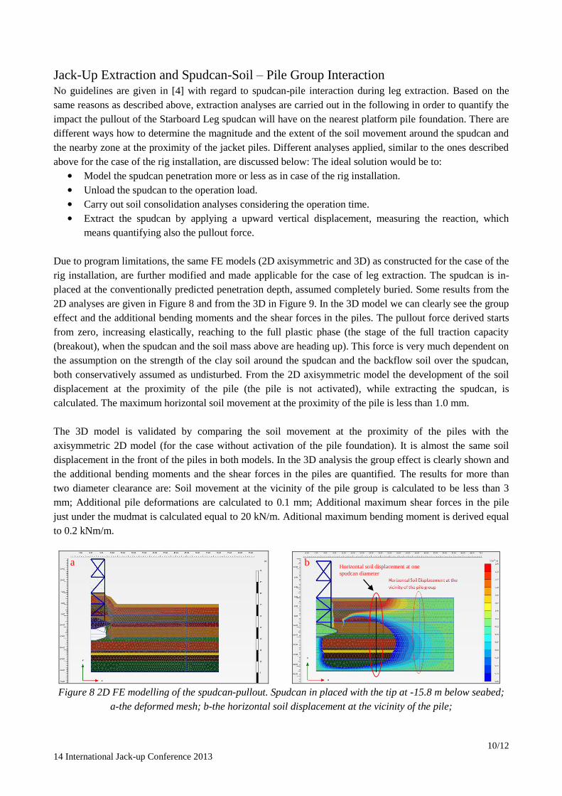
Due to program limitations, the same FE models (2D axisymmetric and 3D) as constructed for the case of the
rig installation, are further modified and made applicable for the case of leg extraction. The spudcan is in-
placed at the conventionally predicted penetration depth, assumed completely buried. Some results from the
2D analyses are given in Figure 8 and from the 3D in Figure 9. In the 3D model we can clearly see the group
effect and the additional bending moments and the shear forces in the piles. The pullout force derived starts
from zero, increasing elastically, reaching to the full plastic phase (the stage of the full traction capacity
(breakout), when the spudcan and the soil mass above are heading up). This force is very much dependent on
the assumption on the strength of the clay soil around the spudcan and the backflow soil over the spudcan,
both conservatively assumed as undisturbed. From the 2D axisymmetric model the development of the soil
displacement at the proximity of the pile (the pile is not activated), while extracting the spudcan, is
calculated. The maximum horizontal soil movement at the proximity of the pile is less than 1.0 mm.
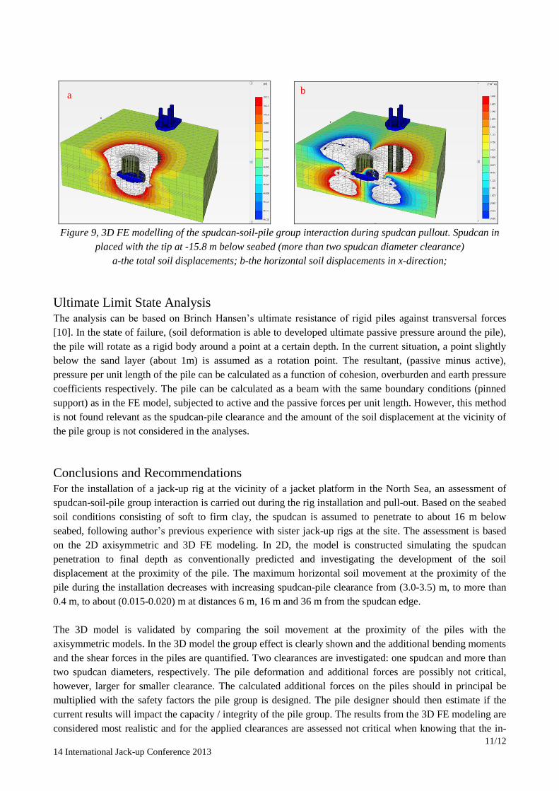
The 3D model is validated by comparing the soil movement at the proximity of the piles with the
axisymmetric 2D model (for the case without activation of the pile foundation). It is almost the same soil
displacement in the front of the piles in both models. In the 3D analysis the group effect is clearly shown and
the additional bending moments and the shear forces in the piles are quantified. The results for more than
two diameter clearance are: Soil movement at the vicinity of the pile group is calculated to be less than 3
mm; Additional pile deformations are calculated to 0.1 mm; Additional maximum shear forces in the pile
just under the mudmat is calculated equal to 20 kN/m. Aditional maximum bending moment is derived equal
to 0.2 kNm/m.
Figure 8 2D FE modelling of the spudcan-pullout. Spudcan in placed with the tip at -15.8 m below seabed;
a-the deformed mesh; b-the horizontal soil displacement at the vicinity of the pile;
a b Horizontal soil displacement at one
spudcan diameter
11/12
14 International Jack-up Conference 2013
Figure 9, 3D FE modelling of the spudcan-soil-pile group interaction during spudcan pullout. Spudcan in
placed with the tip at -15.8 m below seabed (more than two spudcan diameter clearance)
a-the total soil displacements; b-the horizontal soil displacements in x-direction;
Ultimate Limit State Analysis The analysis can be based on Brinch Hansen’s ultimate resistance of rigid piles against transversal forces
[10]. In the state of failure, (soil deformation is able to developed ultimate passive pressure around the pile),
the pile will rotate as a rigid body around a point at a certain depth. In the current situation, a point slightly
below the sand layer (about 1m) is assumed as a rotation point. The resultant, (passive minus active),
pressure per unit length of the pile can be calculated as a function of cohesion, overburden and earth pressure
coefficients respectively. The pile can be calculated as a beam with the same boundary conditions (pinned
support) as in the FE model, subjected to active and the passive forces per unit length. However, this method
is not found relevant as the spudcan-pile clearance and the amount of the soil displacement at the vicinity of
the pile group is not considered in the analyses.
Conclusions and Recommendations For the installation of a jack-up rig at the vicinity of a jacket platform in the North Sea, an assessment of
spudcan-soil-pile group interaction is carried out during the rig installation and pull-out. Based on the seabed
soil conditions consisting of soft to firm clay, the spudcan is assumed to penetrate to about 16 m below
seabed, following author’s previous experience with sister jack-up rigs at the site. The assessment is based
on the 2D axisymmetric and 3D FE modeling. In 2D, the model is constructed simulating the spudcan
penetration to final depth as conventionally predicted and investigating the development of the soil
displacement at the proximity of the pile. The maximum horizontal soil movement at the proximity of the
pile during the installation decreases with increasing spudcan-pile clearance from (3.0-3.5) m, to more than
0.4 m, to about (0.015-0.020) m at distances 6 m, 16 m and 36 m from the spudcan edge.
The 3D model is validated by comparing the soil movement at the proximity of the piles with the
axisymmetric models. In the 3D model the group effect is clearly shown and the additional bending moments
and the shear forces in the piles are quantified. Two clearances are investigated: one spudcan and more than
two spudcan diameters, respectively. The pile deformation and additional forces are possibly not critical,
however, larger for smaller clearance. The calculated additional forces on the piles should in principal be
multiplied with the safety factors the pile group is designed. The pile designer should then estimate if the
current results will impact the capacity / integrity of the pile group. The results from the 3D FE modeling are
considered most realistic and for the applied clearances are assessed not critical when knowing that the in-
b a

12/12
14 International Jack-up Conference 2013
place utilization of the piles is rather modest. However, due to operation flexibility the largest clearance was
finally applied.
Regarding pullout analyses, the 3D FE modeling is also considered most realistic and for the applied
clearance assessed not critical. Any breakout force due to any suction effects developed under the spudcan
might be overcome by applying a lower load for some time in combination with load variations (“pumping
effects”) or by applying available systems of water pressure at the spudcan bottom – soil interface. The load
rate effect has also a large impact on the pull-out capacity. Slow operation is recommend, however not
associated with pauses, which can be the reason for local change of the soil strength. While the legs move
up, the pull-out force will be reduced, as part of the soil above the spudcans will fall down due to stability
issue creating safe slopes, however not giving any critical interaction with the platform piles.
The combined 2D and 3D FE modelling applied for the current jack-up location can be considered a good
approximation for the assessment of spudcan-soil-jacket pile group foundation interaction. For the current
soil conditions and jack-up preloading, even for large clearances consisting of one or more than two spudcan
diameters, there is an impact on the jacket piles, which is quantified and based on that, the jack-up location
determined.
Acknowledgement The authors are grateful to GEO–Danish Geotechnical Institute and Nexen Petroleum UK Limited for
supporting this project.
References /1/ Xie, Y. and Chow, Y. K. (2011), Soil Movements and Pile Responses during Spudcan Penetration, 13
th
International Conference on the Jack-Up Platform, London
/2/ Leung, C. F. and Chow, Y. K. (2012), Experimental and Numerical Studies of Spudcan-Pile
Interaction, Offshore Technology Conference 23053, Texas, USA.
/3/ Kellezi, L. and Sundararajan, S. S. (2012), Impact of the Jack-up rig Installation on the Jacket Platform
Piles Spudcan-Soil-Pile Interaction Analyses, 22nd
European Young Geotechnical Engineers
Conference, Gothenburg, Sweden.
/4/ SNAME, T&R Bulletin 5-5A January 2002, Site Specific Assessment of Mobile Jack-Up Units. The
Society of Naval Architects and Marine Engineers.
/5/ Hansen, J.B. A Revised and Extended Formula for Bearing Capacity. Bulletin No. 28. The Danish
Geotechnical Institute. 1970.
/6/ Plaxis 2D Version 11.01. Finite Element Code for Soil and Rock Analysis. Delft University of
Technology & Plaxis bv. The Netherlands. 2010.
/7/ Plaxis 3D Version 2.2. Foundation Module, Finite Element Code for Soil and Rock Analysis. Delft
University of Technology & Plaxis bv. The Netherlands. 2009.
/8/ Kellezi, L. and Stromann, H. (2003), ‘FEM Analysis of Jack-up Spudcan Penetration for Multi-
Layered Critical Soil Conditions’. Proceeding of BGA International Conference on Foundations,
ICOF2003, Dundee, Scotland, page (410-420).
/9/ Kellezi, L. and Kudsk, G. (2009), ‘Jack-up Foundation, FE Modelling of Punch Through for Sand over
Clay’ 12 International Conf. on Jack-up Platform. Sept. London UK, Proc. page (1-12).
/10/ Hansen B. J. & Christensen N. H. (1961) The ultimate resistance of rigid piles against transversal
forces. Model tests with transversally loaded rigid piles in sand.