sps-a-1 of 12 appendix a · pdf filealignment equipment used: alignment method used: reverse...
TRANSCRIPT
SPS-A-1 of 12
Published: 01/01 Revised:
APPENDIX A
TABLE NO. 1 ROTOR BALANCE CLASSIFICATION EXAMPLES
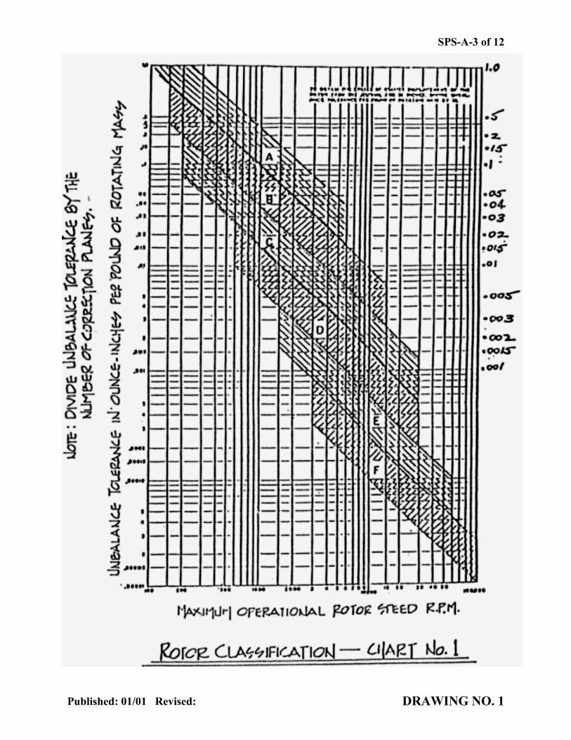
DRAWING NO. 1 ROTOR BALANCE CLASSIFICATION – CHART NO. 1
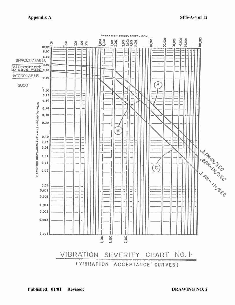
DRAWING NO. 2 VIBRATION SEVERITY – CHART NO. 1
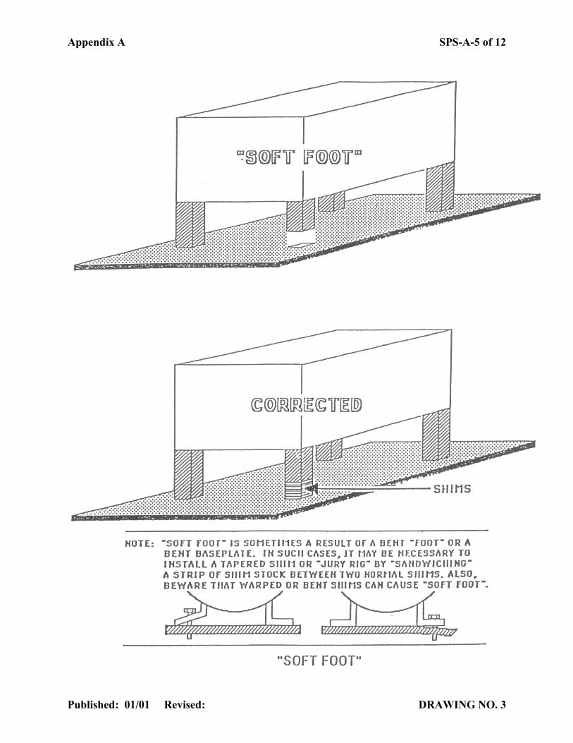
DRAWING NO. 3 SOFT FOOT (DESCRIPTION)
DRAWING NO. 4 SOFT FOOT TEST
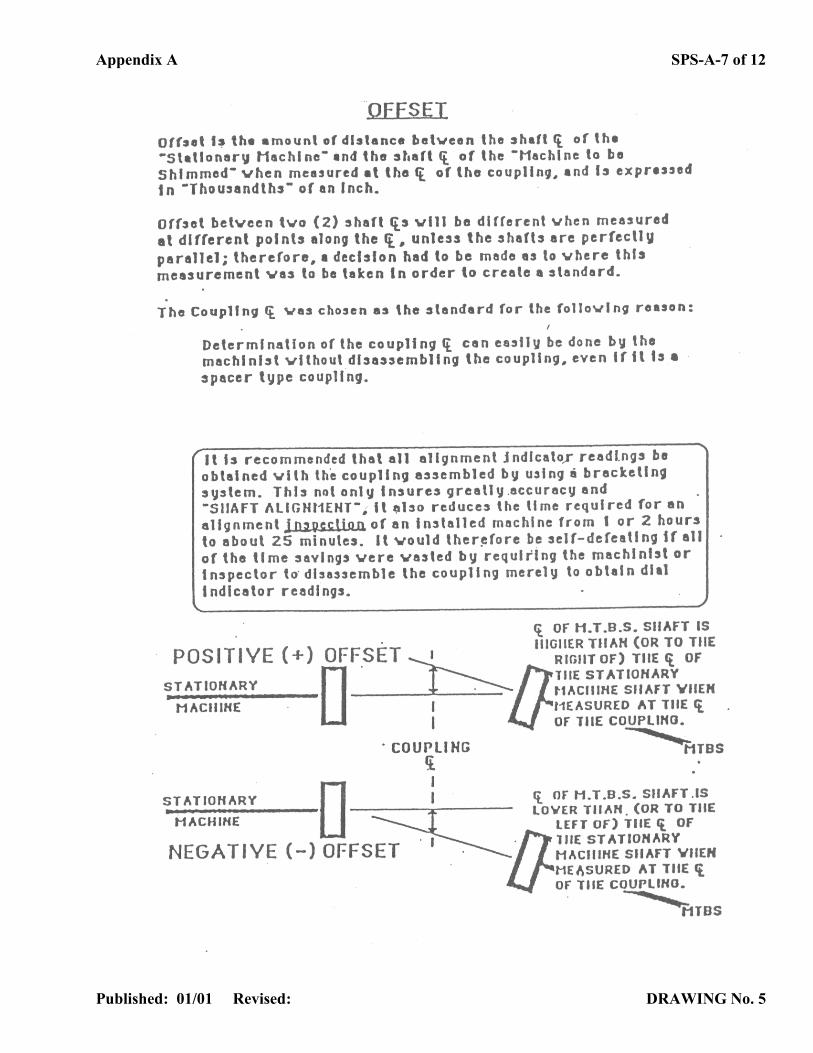
DRAWING NO. 5 OFFSET (SHAFT MISALIGNMENT)
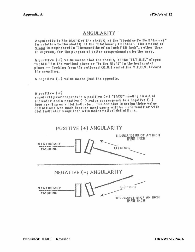
DRAWING NO. 6 ANGULARITY (SHAFT MISALIGNMENT)
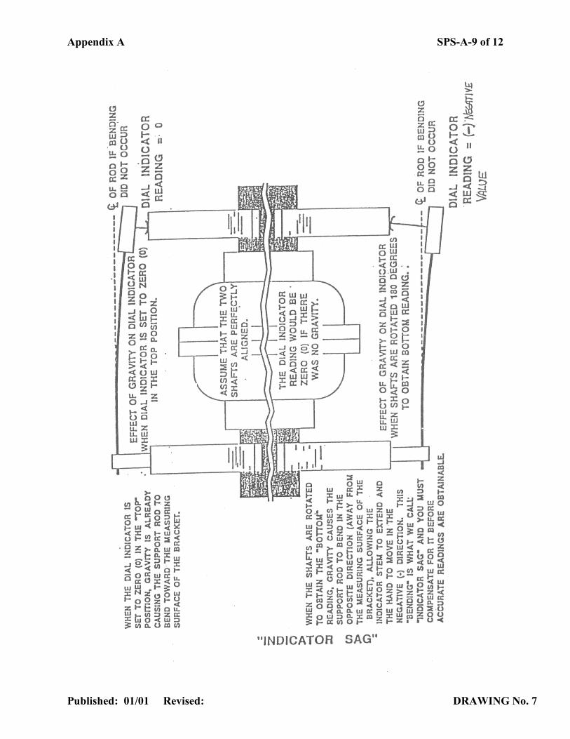
DRAWING NO. 7 INDICATOR SAG
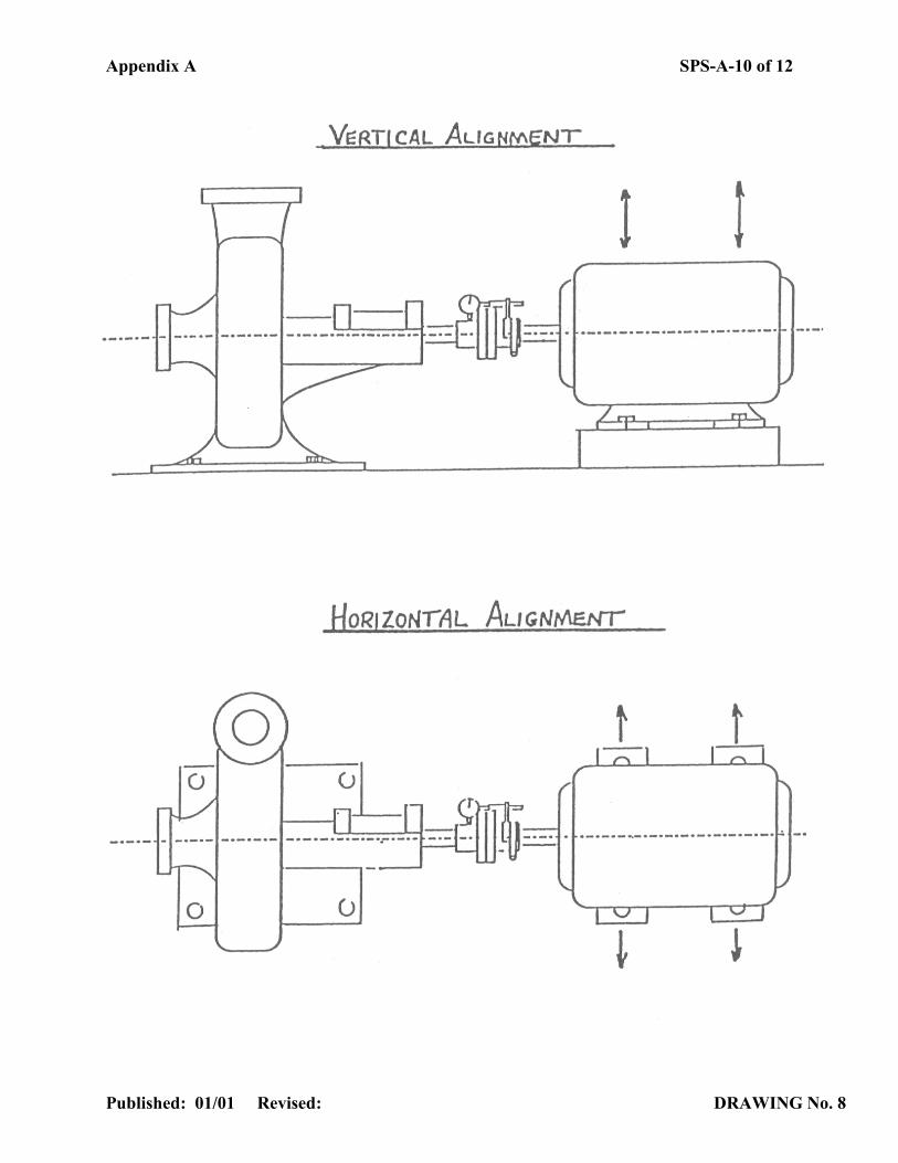
DRAWING NO. 8 VERTICAL VS. HORIZONTAL ALIGNMENT
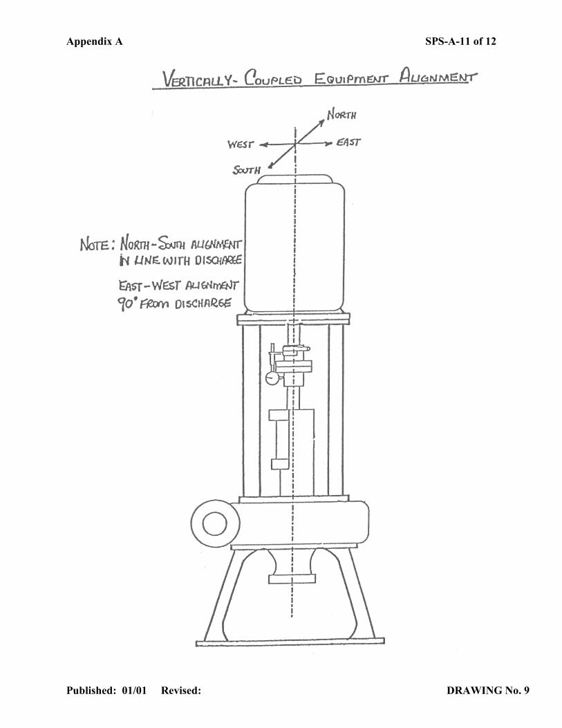
DRAWING NO. 9 VERTICALLY COUPLED EQUIPMENT ALIGNMENT
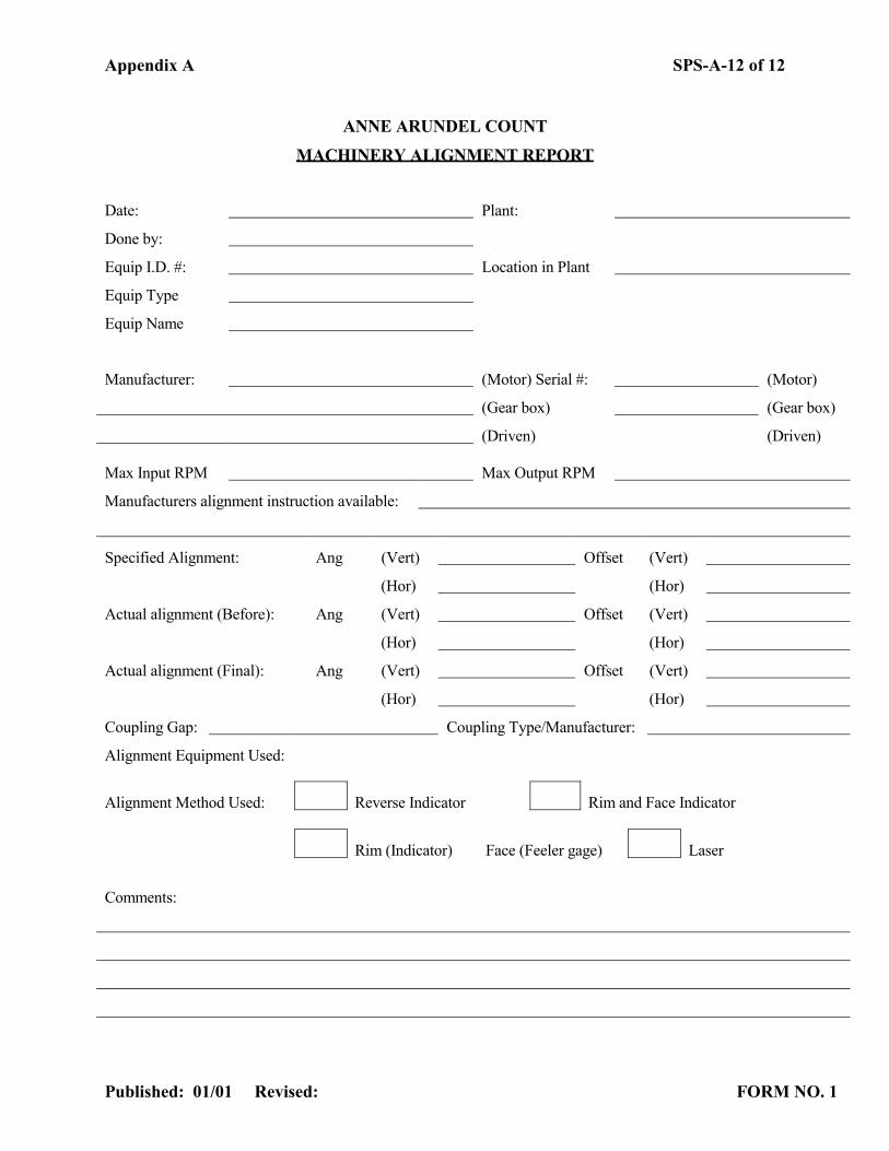
FORM NO. 1 MACHINERY ALIGNMENT REPORT
Appendix A SPS-A-2 of 12
Published: 01/01 Revised: TABLE NO. 1
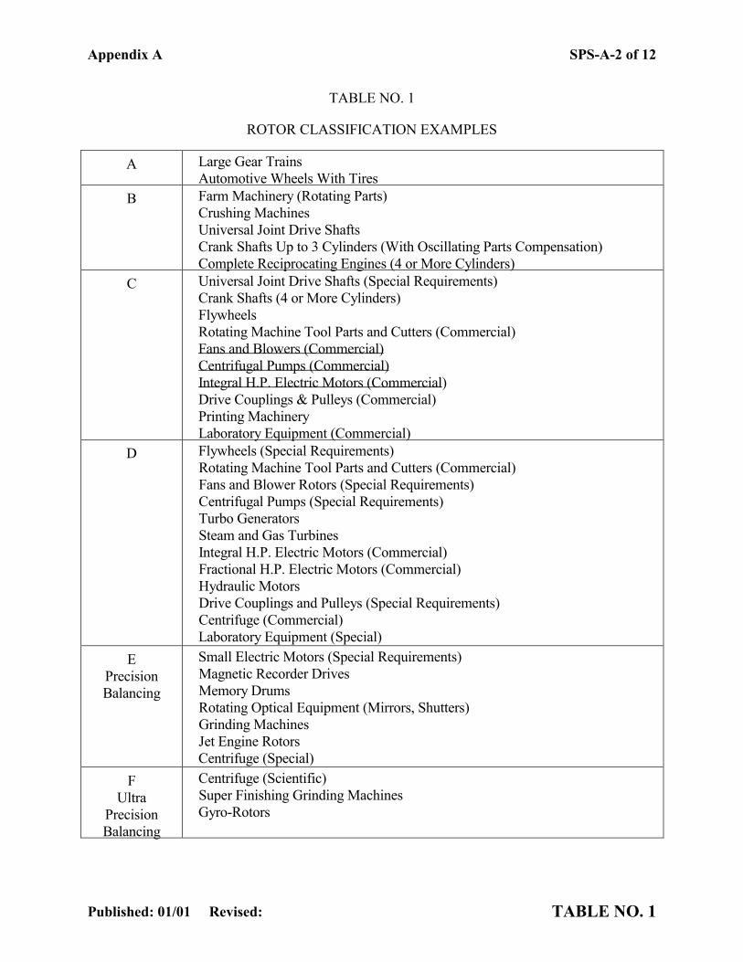
TABLE NO. 1
ROTOR CLASSIFICATION EXAMPLES
A Large Gear Trains Automotive Wheels With Tires
B Farm Machinery (Rotating Parts) Crushing Machines Universal Joint Drive Shafts Crank Shafts Up to 3 Cylinders (With Oscillating Parts Compensation) Complete Reciprocating Engines (4 or More Cylinders)
C Universal Joint Drive Shafts (Special Requirements) Crank Shafts (4 or More Cylinders) Flywheels Rotating Machine Tool Parts and Cutters (Commercial) Fans and Blowers (Commercial) Centrifugal Pumps (Commercial) Integral H.P. Electric Motors (Commercial) Drive Couplings & Pulleys (Commercial) Printing Machinery Laboratory Equipment (Commercial)
D
Flywheels (Special Requirements) Rotating Machine Tool Parts and Cutters (Commercial) Fans and Blower Rotors (Special Requirements) Centrifugal Pumps (Special Requirements) Turbo Generators Steam and Gas Turbines Integral H.P. Electric Motors (Commercial) Fractional H.P. Electric Motors (Commercial) Hydraulic Motors Drive Couplings and Pulleys (Special Requirements) Centrifuge (Commercial) Laboratory Equipment (Special)
E Precision Balancing
Small Electric Motors (Special Requirements) Magnetic Recorder Drives Memory Drums Rotating Optical Equipment (Mirrors, Shutters) Grinding Machines Jet Engine Rotors Centrifuge (Special)
F Ultra
Precision Balancing
Centrifuge (Scientific) Super Finishing Grinding Machines Gyro-Rotors
SPS-A-3 of 12
Published: 01/01 Revised: DRAWING NO. 1
Appendix A SPS-A-4 of 12
Published: 01/01 Revised: DRAWING NO. 2
Appendix A SPS-A-5 of 12
Published: 01/01 Revised: DRAWING NO. 3

Appendix A SPS-A-6 of 12
Published: 01/01 Revised: DRAWING NO. 4
Appendix A SPS-A-7 of 12
Published: 01/01 Revised: DRAWING No. 5
Appendix A SPS-A-8 of 12
Published: 01/01 Revised: DRAWING No. 6
Appendix A SPS-A-9 of 12
Published: 01/01 Revised: DRAWING No. 7
Appendix A SPS-A-10 of 12
Published: 01/01 Revised: DRAWING No. 8
Appendix A SPS-A-11 of 12
Published: 01/01 Revised: DRAWING No. 9
Appendix A SPS-A-12 of 12
Published: 01/01 Revised: FORM NO. 1
ANNE ARUNDEL COUNT MACHINERY ALIGNMENT REPORT
Date: Plant:
Done by:
Equip I.D. #: Location in Plant
Equip Type
Equip Name
Manufacturer: (Motor) Serial #: (Motor)
(Gear box) (Gear box)
(Driven) (Driven)
Max Input RPM Max Output RPM
Manufacturers alignment instruction available:
Specified Alignment: Ang (Vert) Offset (Vert)
(Hor) (Hor)
Actual alignment (Before): Ang (Vert) Offset (Vert)
(Hor) (Hor)
Actual alignment (Final): Ang (Vert) Offset (Vert)
(Hor) (Hor)
Coupling Gap: Coupling Type/Manufacturer:
Alignment Equipment Used:
Alignment Method Used: Reverse Indicator Rim and Face Indicator
Rim (Indicator) Face (Feeler gage) Laser
Comments: