sprinter 2.7 liter diesel fuel injection diagnosissprinter
DESCRIPTION
This document is intended to provide the experienced Dodge diesel technician with theknowledge and skills necessary to service the Sprinter Van common rail fuel system.The course will provide a system overview, component description and location, andsystem and component diagnosis.TRANSCRIPT

Sprinter 2.7L Diesel Fuel Injection Diagnosis
Sprinter 2.7L Diesel Fuel Injection Diagnosis
i
TABLE OF CONTENTS
TABLE OF CONTENTS . . . . . . . . . . . . . . . . . . . . . . . . . . . . . . . . . . . . . . . . . . iACRONYMS AND ABBREVIATIONS . . . . . . . . . . . . . . . . . . . . . . . . . . . . . . . . . 1COURSE OBJECTIVES . . . . . . . . . . . . . . . . . . . . . . . . . . . . . . . . . . . . . . . . . . 2MODULE 1 COMPONENT LOCATION . . . . . . . . . . . . . . . . . . . . . . . . . . . . . . . 3ENGINE DESCRIPTION . . . . . . . . . . . . . . . . . . . . . . . . . . . . . . . . . . . . . . . . . . . . . 3
FUEL SYSTEM COMPONENTS . . . . . . . . . . . . . . . . . . . . . . . . . . . . . . . . . . . . . . . 4
ACTIVITY 1: COMPONENT LOCATION WALKAROUND . . . . . . . . . . . . . . . . . . . 5TASK 1: UNDER THE HOOD COMPONENTS (GROUP 1) . . . . . . . . . . . . . . . . . . 5TASK 2: COMPONENTS UNDER VEHICLE (GROUP 2) . . . . . . . . . . . . . . . . . . . 6MODULE 2 FUEL SYSTEM MECHANICAL COMPONENTS . . . . . . . . . . . . . . . . 7SAFETY . . . . . . . . . . . . . . . . . . . . . . . . . . . . . . . . . . . . . . . . . . . . . . . . . . . . . . . . 7
GENERAL DESCRIPTION . . . . . . . . . . . . . . . . . . . . . . . . . . . . . . . . . . . . . . . . . . . 7
FUEL FLOW . . . . . . . . . . . . . . . . . . . . . . . . . . . . . . . . . . . . . . . . . . . . . . . . . . . . . 8
LOW-PRESSURE FUEL CIRCUIT COMPONENTS . . . . . . . . . . . . . . . . . . . . . . . . . . 9
FUEL TANK . . . . . . . . . . . . . . . . . . . . . . . . . . . . . . . . . . . . . . . . . . . . . . . . . . . . . . 9
FUEL COOLER . . . . . . . . . . . . . . . . . . . . . . . . . . . . . . . . . . . . . . . . . . . . . . . . . . . 9
PRESSURE COMPENSATION/VENTILATION . . . . . . . . . . . . . . . . . . . . . . . . . . . . . 9
FUEL TANK MODULE . . . . . . . . . . . . . . . . . . . . . . . . . . . . . . . . . . . . . . . . . . . . . 10
FUEL FILTER . . . . . . . . . . . . . . . . . . . . . . . . . . . . . . . . . . . . . . . . . . . . . . . . . . . 11
PREHEATING VALVE . . . . . . . . . . . . . . . . . . . . . . . . . . . . . . . . . . . . . . . . . . . . . 13
FUEL LINES . . . . . . . . . . . . . . . . . . . . . . . . . . . . . . . . . . . . . . . . . . . . . . . . . . . . 14
LOW PRESSURE FUEL LINES . . . . . . . . . . . . . . . . . . . . . . . . . . . . . . . . . . . . . . . 14
LOW PRESSURE PUMP . . . . . . . . . . . . . . . . . . . . . . . . . . . . . . . . . . . . . . . . . . . . 15
ACTIVITY 2.1 LOW FUEL PRESSURE PUMP . . . . . . . . . . . . . . . . . . . . . . . . . 17HIGH-PRESSURE FUEL CIRCUIT COMPONENTS . . . . . . . . . . . . . . . . . . . . . . . . 18
HIGH PRESSURE PUMP . . . . . . . . . . . . . . . . . . . . . . . . . . . . . . . . . . . . . . . . . . . 18
FUEL RAIL . . . . . . . . . . . . . . . . . . . . . . . . . . . . . . . . . . . . . . . . . . . . . . . . . . . . . 22
FUEL INJECTORS . . . . . . . . . . . . . . . . . . . . . . . . . . . . . . . . . . . . . . . . . . . . . . . . 23
MODULE 3 ECM INPUTS . . . . . . . . . . . . . . . . . . . . . . . . . . . . . . . . . . . . . . . 27

Sprinter 2.7L Diesel Fuel Injection Diagnosis
ii
POSITION SENSORS . . . . . . . . . . . . . . . . . . . . . . . . . . . . . . . . . . . . . . . . . . . . . . 29
CRANKSHAFT POSITION SENSOR (CKP) . . . . . . . . . . . . . . . . . . . . . . . . . . . . . . . 29
OPERATION . . . . . . . . . . . . . . . . . . . . . . . . . . . . . . . . . . . . . . . . . . . . . . . . . . . . 29
CAMSHAFT POSITION SENSOR (CMP) . . . . . . . . . . . . . . . . . . . . . . . . . . . . . . . . 31
OPERATION . . . . . . . . . . . . . . . . . . . . . . . . . . . . . . . . . . . . . . . . . . . . . . . . . . . . 32
INJECTION TIMING SYNCHRONIZATION . . . . . . . . . . . . . . . . . . . . . . . . . . . . . . 34
ACTIVITY 3.1 CAM AND CRANK SENSORS . . . . . . . . . . . . . . . . . . . . . . . . . 35ACTIVITY 3.2 ACCELERATOR PEDAL ACTIVITY . . . . . . . . . . . . . . . . . . . . . 41PRESSURE SENSORS . . . . . . . . . . . . . . . . . . . . . . . . . . . . . . . . . . . . . . . . . . . . . 43
BOOST PRESSURE SENSOR . . . . . . . . . . . . . . . . . . . . . . . . . . . . . . . . . . . . . . . 43
OPERATION . . . . . . . . . . . . . . . . . . . . . . . . . . . . . . . . . . . . . . . . . . . . . . . . . . . . 44
BAROMETRIC SENSOR . . . . . . . . . . . . . . . . . . . . . . . . . . . . . . . . . . . . . . . . . . . 46
FUEL RAIL PRESSURE SENSOR . . . . . . . . . . . . . . . . . . . . . . . . . . . . . . . . . . . . . 46
OPERATION . . . . . . . . . . . . . . . . . . . . . . . . . . . . . . . . . . . . . . . . . . . . . . . . . . . . 47
LOW FUEL PRESSURE SENSOR . . . . . . . . . . . . . . . . . . . . . . . . . . . . . . . . . . . . . 49
TEMPERATURE SENSORS . . . . . . . . . . . . . . . . . . . . . . . . . . . . . . . . . . . . . . . . . 52
INTAKE AIR TEMPERATURE SENSOR (IAT) . . . . . . . . . . . . . . . . . . . . . . . . . . . . 52
COOLANT TEMPERATURE SENSOR . . . . . . . . . . . . . . . . . . . . . . . . . . . . . . . . . . 54
FUEL TEMPERATURE SENSOR . . . . . . . . . . . . . . . . . . . . . . . . . . . . . . . . . . . . . 56
ENGINE OIL SENSOR . . . . . . . . . . . . . . . . . . . . . . . . . . . . . . . . . . . . . . . . . . . . . 58
SWITCH INPUTS . . . . . . . . . . . . . . . . . . . . . . . . . . . . . . . . . . . . . . . . . . . . . . . . . 62
KICK-DOWN SWITCH . . . . . . . . . . . . . . . . . . . . . . . . . . . . . . . . . . . . . . . . . . . . . 62
SPEED CONTROL SWITCH . . . . . . . . . . . . . . . . . . . . . . . . . . . . . . . . . . . . . . . . . 62
MASS AIR FLOW SENSOR(MAF) . . . . . . . . . . . . . . . . . . . . . . . . . . . . . . . . . . . . . 65
OPERATION . . . . . . . . . . . . . . . . . . . . . . . . . . . . . . . . . . . . . . . . . . . . . . . . . . . . 65
WATER IN FUEL SENSOR (WIF) . . . . . . . . . . . . . . . . . . . . . . . . . . . . . . . . . . . . . 67
GLOW PLUG MODULE . . . . . . . . . . . . . . . . . . . . . . . . . . . . . . . . . . . . . . . . . . . . 69
ACM ENHANCED ACCIDENT RESPONSE INPUT . . . . . . . . . . . . . . . . . . . . . . . . . 71
INDIRECT INPUTS . . . . . . . . . . . . . . . . . . . . . . . . . . . . . . . . . . . . . . . . . . . . . . . 73
CAN BUS INPUTS . . . . . . . . . . . . . . . . . . . . . . . . . . . . . . . . . . . . . . . . . . . . . . . . 73
ACTIVITY 3.3 ENGINE SENSORS . . . . . . . . . . . . . . . . . . . . . . . . . . . . . . . . 74

Sprinter 2.7L Diesel Fuel Injection Diagnosis
iii
ACTIVITY 3.4 CRUISE CONTROL SWITCH . . . . . . . . . . . . . . . . . . . . . . . . . 76MODULE 4 ECM CONTROL AND OUTPUTS . . . . . . . . . . . . . . . . . . . . . . . . . 77ELECTRONIC CONTROL MODULE (ECM) . . . . . . . . . . . . . . . . . . . . . . . . . . . . . . 77
OPERATION/CONTROL STRATEGIES . . . . . . . . . . . . . . . . . . . . . . . . . . . . . . . . . 78
ECM OUTPUTS . . . . . . . . . . . . . . . . . . . . . . . . . . . . . . . . . . . . . . . . . . . . . . . . . . 82
RELAYS . . . . . . . . . . . . . . . . . . . . . . . . . . . . . . . . . . . . . . . . . . . . . . . . . . . . . . . 82
GLOW PLUG MODULE . . . . . . . . . . . . . . . . . . . . . . . . . . . . . . . . . . . . . . . . . . . . 83
FUEL OUTPUTS . . . . . . . . . . . . . . . . . . . . . . . . . . . . . . . . . . . . . . . . . . . . . . . . . 87
INJECTORS . . . . . . . . . . . . . . . . . . . . . . . . . . . . . . . . . . . . . . . . . . . . . . . . . . . . 87
FUEL PRESSURE SOLENOID . . . . . . . . . . . . . . . . . . . . . . . . . . . . . . . . . . . . . . . 93
HIGH PRESSURE PUMP FUEL SHUTOFF VALVE . . . . . . . . . . . . . . . . . . . . . . . . 95
ACTIVITY 4.1 SHOP DEMONSTRATION OF FUEL RELATED OUTPUTS . . . . . 96INTAKE/EXHAUST OUTPUTS . . . . . . . . . . . . . . . . . . . . . . . . . . . . . . . . . . . . . . . 97
BOOST PRESSURE SOLENOID . . . . . . . . . . . . . . . . . . . . . . . . . . . . . . . . . . . . . . 97
OPERATION . . . . . . . . . . . . . . . . . . . . . . . . . . . . . . . . . . . . . . . . . . . . . . . . . . . . 97
EGR VALVE . . . . . . . . . . . . . . . . . . . . . . . . . . . . . . . . . . . . . . . . . . . . . . . . . . . . 98
OPERATION . . . . . . . . . . . . . . . . . . . . . . . . . . . . . . . . . . . . . . . . . . . . . . . . . . . . 99
MIL LAMP . . . . . . . . . . . . . . . . . . . . . . . . . . . . . . . . . . . . . . . . . . . . . . . . . . . . . 100
DATA LINK CONNECTOR . . . . . . . . . . . . . . . . . . . . . . . . . . . . . . . . . . . . . . . . . 101
CAN BUS OUTPUTS . . . . . . . . . . . . . . . . . . . . . . . . . . . . . . . . . . . . . . . . . . . . . 102
ACTIVITY 4.2 ACTIVATIONS OF INTAKE/EXHAUST DEVICES . . . . . . . . . . 103MODULE 5 ENGINE DIAGNOSIS . . . . . . . . . . . . . . . . . . . . . . . . . . . . . . . . 105SIX-STEP DIAGNOSTIC PROCESS . . . . . . . . . . . . . . . . . . . . . . . . . . . . . . . . . . 106
TYPES OF EXHAUST SMOKE . . . . . . . . . . . . . . . . . . . . . . . . . . . . . . . . . . . . . . 107
NO DTC DIAGNOSIS . . . . . . . . . . . . . . . . . . . . . . . . . . . . . . . . . . . . . . . . . . . . . 108
HIGH-PRESSURE DIAGNOSIS . . . . . . . . . . . . . . . . . . . . . . . . . . . . . . . . . . . . . 108
DIAGNOSIS WITH RELATED FAULT CODES . . . . . . . . . . . . . . . . . . . . . . . . . . . 108
COMMON POINT ANALYSIS . . . . . . . . . . . . . . . . . . . . . . . . . . . . . . . . . . . . . . . 109
DIAGNOSIS WITHOUT RELATED FAULT CODES . . . . . . . . . . . . . . . . . . . . . . . 114
COMPLAINT: ROUGH IDLE/ENGINE KNOCKS AT IDLE . . . . . . . . . . . . . . . . . . 114
COMPLAINT: ENGINE CRANKS, BUT DOESN'T START . . . . . . . . . . . . . . . . . . . 115

Sprinter 2.7L Diesel Fuel Injection Diagnosis
iv
COMPLAINT: POWER LOSS/ENGINE DIES UNDER LOAD . . . . . . . . . . . . . . . . 116
COMPLAINT: BLACK SMOKE . . . . . . . . . . . . . . . . . . . . . . . . . . . . . . . . . . . . . . 117
COMPLAINT: ENGINE RPM DROPS INTERMITTENTLY . . . . . . . . . . . . . . . . . . . 118
ACTIVITY 5.1 : TROUBLESHOOTING PROBLEMS ON VEHICLE . . . . . . . . . . 119TASK 1 (GROUP 1) LOW POWER AND ENGINE RUNNING ROUGH . . . . . . . . 119TASK 1 (GROUP 2) ENGINE RUNNING ROUGH AND LOW POWER . . . . . . . 120TASK 2 (GROUP 1) ENGINE WON’T RUN . . . . . . . . . . . . . . . . . . . . . . . . . . 121TASK 2 (GROUP 2) ENGINE WON’T RUN . . . . . . . . . . . . . . . . . . . . . . . . . . 122APPENDIX . . . . . . . . . . . . . . . . . . . . . . . . . . . . . . . . . . . . . . . . . . . . . . . . . 123OSCILLOSCOPE PATTERNS. . . . . . . . . . . . . . . . . . . . . . . . . . . . . . . . . . . . . . . . 123
SENSOR REFERENCE . . . . . . . . . . . . . . . . . . . . . . . . . . . . . . . . . . . . . . . . . . . 134
RETROFITTING SPEED CONTROL . . . . . . . . . . . . . . . . . . . . . . . . . . . . . . . . . . . 136

Sprinter 2.7L Diesel Fuel Injection Diagnosis
1
ACRONYMS AND ABBREVIATIONS
The following is a list of acronyms used throughout this course:
ACM Airbag Control ModuleATC Automatic Temperature ControlCAB Controller Antilock Brakes (ABS)CAN Controller Area NetworkCKP Crank Position SensorCMP Cam Position SensorDLC Data Link ConnectorDRBIII Diagnostic Readout Box Third GenerationDTC Diagnostic Trouble CodeECM Engine Control ModuleECT Engine Coolant TemperatureEEPROM Electrical Erasable Programmable Read Only MemoryIAT Intake Air Temperature SensorIC Instrument ClusterK-Line Serial Communications Line for DiagnosticsLCD Liquid Crystal DisplayMAF Mass Air Flow SensorMIL Malfunction Indicator LampNTC Negative Temperature Coefficient (Thermistor)OBDII On Board Diagnostics Second GenerationPTC Positive Temperature CoefficientRAM Random Access MemorySCI Serial Communications Interface (K-Line may also be used)SKREEM Sentry Key Remote (Electronic) Entry ModuleSLA Shift Lever AssemblySRS Supplemental Restraint SystemTCM Transmission Control ModuleTERMINAL 15 Ignition Powered CircuitTERMINAL 30 Battery Powered CircuitTERMINAL 58 Circuit That is Powered When Parking Lights are ONTERMINAL D+ Circuit That is Powered When The Engine is RunningWIF Water-in-Fuel Sensor

Sprinter 2.7L Diesel Fuel Injection Diagnosis
2
COURSE OBJECTIVES
This course is intended to provide the experienced Dodge diesel technician with the knowledge and skills necessary to service the Sprinter Van common rail fuel system. The course will provide a system overview, component description and location, and system and component diagnosis.
After completing this course, you should be able to: Identify and locate all fuel system components Describe the fuel flow of the Sprinter common-rail system Identify the operation of fuel system components Identify the inputs, control and outputs of the fuel system Diagnose fuel system failures with the DRB IIII diagnostic tool Perform tests using special tools as specified in the service information

Sprinter 2.7L Diesel Fuel Injection Diagnosis
3
MODULE 1 COMPONENT LOCATION
ENGINE DESCRIPTION
The Sprinter 2.7 liter diesel engine utilizes the following major systems: Electronic direct injection Four-valve per cylinder technology Symmetrical combustion chambers with the injectors positioned in the center Cooled exhaust gas recirculation Variable Geometry Turbocharging Intercooling
Figure 1 Sprinter 2.7 L Diesel Engine
Common rail direct injection stores fuel in a fuel rail under high pressure. Injection is cylinder-selective and delivered as required. Advantages include:
Reduction in fuel consumption High torque at low engine speeds Reduction in noise emissions

Sprinter 2.7L Diesel Fuel Injection Diagnosis
4
FUEL SYSTEM COMPONENTS
The Sprinter 2.7 L Diesel Engine has the following fuel system components: Fuel tank Fuel cooler Fuel lines Fuel filter Low pressure pump High pressure pump Fuel rail Fuel injectors
Figure 2 Fuel System Components
1 Fuel Rail 5 Fuel Filter2 High Pressure Pump 6 Fuel Cooler3 Fuel Lines 7 Fuel Tank4 Low Pressure Pump 8 Fuel Injector
1
2
4
5
3
6
7
8

Sprinter 2.7L Diesel Fuel Injection Diagnosis
5
ACTIVITY 1: COMPONENT LOCATION WALKAROUND
The purpose of this activity is to familiarize the technician with the location of the fuel system components.
TASK 1: UNDER THE HOOD COMPONENTS (GROUP 1)
Using service information, locate the following components in the engine compart-ment. Mark the position of the components on the drawings below using the numbers from this list.
1. Fuel filter2. Low pressure pump3. High pressure pump4. Fuel common rail5. Fuel injectors6. Fuel return line, including leak port lines from injectors
Figure 3 Under the hood components

Sprinter 2.7L Diesel Fuel Injection Diagnosis
6
TASK 2: COMPONENTS UNDER VEHICLE (GROUP 2)
Locate the following components under the vehicle using the service information. Mark the position of the components on the drawings below using the numbers from this list.
1. Fuel tank2. Fuel tank sending unit3. Roll-over valves4. Pressure control valve5. Fuel Supply line6. Fuel Return line7. Heater booster line8. Fuel cooler
Figure 4 Under the vehicle components
Sprinter 2.7L Diesel Fuel Injection Diagnosis
7
MODULE 2 FUEL SYSTEM MECHANICAL COMPONENTS
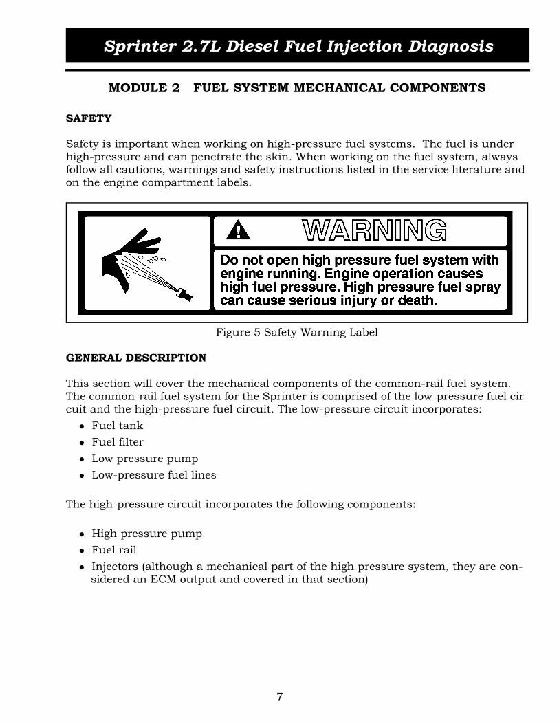
SAFETY
Safety is important when working on high-pressure fuel systems. The fuel is under high-pressure and can penetrate the skin. When working on the fuel system, always follow all cautions, warnings and safety instructions listed in the service literature and on the engine compartment labels.
Figure 5 Safety Warning Label
GENERAL DESCRIPTION
This section will cover the mechanical components of the common-rail fuel system. The common-rail fuel system for the Sprinter is comprised of the low-pressure fuel cir-cuit and the high-pressure fuel circuit. The low-pressure circuit incorporates:
Fuel tank Fuel filter Low pressure pump Low-pressure fuel lines
The high-pressure circuit incorporates the following components:
High pressure pump Fuel rail Injectors (although a mechanical part of the high pressure system, they are con-sidered an ECM output and covered in that section)

Sprinter 2.7L Diesel Fuel Injection Diagnosis
8
Figure 6 Common Rail Fuel Circuits
FUEL FLOW
Fuel Supply
The fuel flows from the fuel tank, through the fuel filter to the low pressure pump. From the low pressure pump, the fuel flows to the inlet side of the high pressure pump.
High Pressure Circuit
Fuel flows from the outlet side of the high pressure pump to the common rail to the injectors
Fuel Return
Return fuel from the injectors (control fuel), the pressure control valve and high pres-sure fuel pump flows into the fuel return system and is returned to the fuel filter or the fuel tank (depending on the temperature of the returned fuel).
Approximately 70% to 80% of the fuel supplied to the high pressure system is returned. The main function of this fuel is to cool and lubricate the fuel system compo-nents.

Sprinter 2.7L Diesel Fuel Injection Diagnosis
9
LOW-PRESSURE FUEL CIRCUIT COMPONENTS
FUEL TANK
A plastic fuel tank with a capacity of 25 gallons is mounted under the left/center side of the vehicle. The tank contains a serviceable fuel tank module (Figure 8) equipped with 2 fuel lines: a fuel supply line and a fuel return line. A section of the fuel return line is coiled at the rear section of the tank, and functions as a fuel cooler. An addi-tional fuel supply line is installed on vehicles equipped with the optional heater booster/auxiliary heater.
Figure 7 Fuel Tank
FUEL COOLER
To avoid damage to plastic parts in the fuel tank, an aluminum fuel cooler coil is installed behind the tank to help drop the temperature of fuel returning to the tank. Hot fuel also results in low power output of the engine.
PRESSURE COMPENSATION/VENTILATION
A roll-over valve installed in each of the two vent valves helps to prevent fuel leakage when the tank is tilted or turned. Pressure compensation is carried out by a separate pressure control valve in the common vent line.
1 Fuel Tank Module 3 Pressure Control Valve2 Rollover Valves 4 Fuel Cooler
2
3
1
4

Sprinter 2.7L Diesel Fuel Injection Diagnosis
10
FUEL TANK MODULE
The fuel level sensor module is installed in the top of the fuel tank. It contains the fol-lowing components:
Fuel gauge sending unit Fuel supply/return pick-up tubes Fuel reservoir/baffle Suction jet pump
Figure 8 Fuel Tank Module
1 Fuel Level Sending Unit Float 4 Heater Booster Pick-Up (Option)2 Fuel Level Variable Resistor 5 Fuel Outlet (Inlet to Fuel System)3 Suction Jet Pump 6 Fuel Return
1
2
34
5
6
SIDE VIEWTOP VIEW

Sprinter 2.7L Diesel Fuel Injection Diagnosis
11
Suction Jet Pump
The suction jet pump (Figure 9) helps fill the fuel tank module reservoir with fuel up to a certain level. When cornering with a low fuel level in the fuel tank the reservoir pre-vents the system from drawing in air. The nozzle (2) in the suction jet pump (1) accel-erates the returning fuel (4). The fuel jet produces a differential pressure, which increases the fuel supply to the reservoir (6).
Figure 9 Suction Jet Pump
FUEL FILTER
The fuel filter is mounted on top of the left engine mount bracket. The filter has the task of cleaning the fuel before it is fed through the fuel supply pump to the high-pres-sure system and ultimately to the injector nozzles. The fuel filter incorporates the fol-lowing components:
5 micron fuel filter element Water separator Bleed screw Water drain valve Preheating valve WIF sensor
1 Suction Jet Pump 4 Return Fuel2 Nozzle 5 Fuel in Tank3 Return Pick-Up Tube 6 Tank Module Reservoir
1 2
5
6
3
4
Sprinter 2.7L Diesel Fuel Injection Diagnosis
12
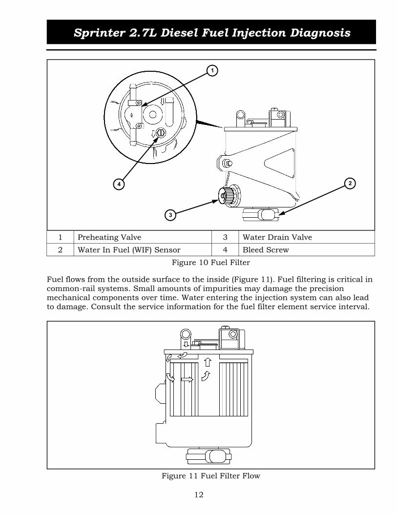
Figure 10 Fuel Filter
Fuel flows from the outside surface to the inside (Figure 11). Fuel filtering is critical in common-rail systems. Small amounts of impurities may damage the precision mechanical components over time. Water entering the injection system can also lead to damage. Consult the service information for the fuel filter element service interval.
Figure 11 Fuel Filter Flow
1 Preheating Valve 3 Water Drain Valve2 Water In Fuel (WIF) Sensor 4 Bleed Screw
1
2
3
4

Sprinter 2.7L Diesel Fuel Injection Diagnosis
13
Water Drain Valve
A water reservoir is located at the bottom of the filter to collect any water contained in the fuel. A drain valve is mounted on the side of the filter housing. A hose can be installed to avoid spilling fuel. The bleed screw must also be opened when draining water. The filter should be drained if the WIF light is illuminated.
Bleeding the system
The fuel system is bled automatically during engine start. Do not interrupt start oper-ation.
PREHEATING VALVE
A fuel preheating valve is mounted on top of the fuel filter housing to ensure proper operation in colder weather. The preheating valve is a bimetal controlled valve that directs return fuel to either the fuel filter, at fuel temperature below 30°C (86°F), or the fuel cooler, at fuel temperatures above 30°C (86°F).
Preheating (A)
If the fuel temperature is less than about 30°C (86 °F), the bimetal plate (2) shuts off the return passage to the fuel tank (b). The fuel from the rail (a) flows into the fuel filter (c), which in turn causes the ball (3) to be pressed off its seat and opens the passage in the direction of the fuel filter.If air is present in the fuel system, for example if the fuel tank has been run empty, the ball (3) shuts off the passage in the direction of the fuel filter (c) and the air is directed along the bypass (1) to the fuel tank.
No preheating (B)
If the fuel temperature is greater than about 30°C (86 °F), the bimetal plate (2) shuts off the passage to the fuel filter (c). The fuel from the rail (a) now flows into the return line to the fuel tank (b).

Sprinter 2.7L Diesel Fuel Injection Diagnosis
14
Figure 12 Preheating Valve
FUEL LINES
The fuel lines connect the components of the common rail fuel system together to form a closed fuel system. The clear plastic line fittings are not individually replaceable.
LOW PRESSURE FUEL LINES
The fuel feed and return lines installed in the chassis are made of steel. The under-hood low pressure fuel lines (Figure 13) are made of the following materials:
PA12 (Polyamide 12) clear tubing—Used in the high-pressure pump return line, the filter to low-pressure pump supply line, and the low-pressure pump to high-pressure pump supply line. The fittings and locking clips are not replaceable. HNBR (Hydrogenated Nitrile Butadiene Rubber) hose—Used in the fuel return banjo fitting to the fuel temperature sensor housing and the return line from fuel temperature sensor housing to the preheating valve. Standard clamps are used. Braided rubber hose—Used in the fuel return line from the injectors.
1 Bypass B No Preheating2 Bimetal Plate a Fuel Return From Rail3 Ball b Fuel Return To Fuel TankA Preheating Stage c Connection To To Fuel Filter
B
a b a b
c c
A1
23

Sprinter 2.7L Diesel Fuel Injection Diagnosis
15
Figure 13 Low Pressure Fuel Lines
LOW PRESSURE PUMP
The low pressure pump is located at the right-hand side of the engine block above the high pressure pump. The low pressure pump draws the fuel out of the fuel tank through the fuel filter, and pumps it to the high pressure pump.
Figure 14 Low Pressure Pump
1 Braided Rubber Hose 3 PA12 (Nylon) Clear Tubing2 HNBR Rubber Hose
1
2
3

Sprinter 2.7L Diesel Fuel Injection Diagnosis
16
The low pressure gear pump is driven by the intake camshaft. There is a partial vac-uum of -0.2 to -0.4 bar (5.905 to 11.8 in.Hg) on its inlet side, and a low fuel pressure on its delivery side.
Figure 15 Low Pressure Pump Components
During cranking, the output pressure is 0.4 to 1.5 bar (6 to 22 psi), at idle it is 2.0 to 2.5 bar (29 to 36 psi), and normal engine running pressure is limited to a maximum of 3.5 ± 0.5 bar (51 ± 7 psi) by the pressure relief valve.
Figure 16 Low Pressure Pump Relief Valve
If the tank has been run empty, the fuel supply pump may have to be primed with fuel so that it can draw fuel again.
1 Outlet Side 4 Driven Gear2 Inlet Side A Fuel Delivery Pressure3 Driving Gear B Partial Vacuum
1 2
3
4
AB

Sprinter 2.7L Diesel Fuel Injection Diagnosis
17
ACTIVITY 2.1 LOW FUEL PRESSURE PUMP
The purpose of this activity is to discuss diagnosis of the low-pressure fuel pump.
1. Using service information, connect the fuel pressure gauge to the low-pressure fuel system.
2. Connect the DRB III and multiplexer to the DLC.3. Navigate to the Engine System Test and activate the Compression test.4. Monitor the fuel pressure on the gauge while the engine is cranking.5. What is the pressure reading with the engine cranking?
6. Page back on DRB III and select sensors.7. Locate the Fuel Low Pressure sensor reading.8. Start the engine and allow it to idle.9. What is the pressure reading with the engine running at idle?
10. Compare the reading on the gauge to the reading under the sensors screen on DRB III.
11. Does the reading on the DRB III match the gauge reading?
12. Increase engine speed to maximum.13. What is the pressure reading with the engine running at full speed?
14. Does the reading on the DRB III match the gauge reading?
15. Does the vehicle you are testing meet the specifications published in the service manual?
16. If the readings were lower than the published specifications, what could be the possible cause?
17. What part of the six step diagnosis process would you connect the low pressure fuel gauge?
18. Remove the fuel pressure gauge and reassemble the van.19. Start the van and check for fuel leaks. Correct any leakage you find.

Sprinter 2.7L Diesel Fuel Injection Diagnosis
18
HIGH-PRESSURE FUEL CIRCUIT COMPONENTS
HIGH PRESSURE PUMP
The high pressure pump is mounted to the front of the cylinder head. The pump is driven at about 1.3 times the speed of the camshaft and requires no timing. Fuel that enters the high-pressure pump is pressurized between 200-1350 bar (2900 - 20,000 psi). The pressurized fuel is then supplied to the fuel rail.The high pressure pump is a radial piston pump with three pistons arranged at an angle of 120° and a shutdown solenoid located in one of the elements to assist with fuel temperature regulation.
Figure 17 High Pressure Pump
1 High Pressure Pump Housing 4 Fuel Shutdown Solenoid2 O-Ring 5 High Pressure Port3 Drive Plate 6 Direction Of Rotation
1
2
3
45
6

Sprinter 2.7L Diesel Fuel Injection Diagnosis
19
Operation
Low Pressure Side
The fuel supplied by the low pressure pump flows through the fuel feed (1) to the throttle valve (5). Any air entrained by the fuel is directed through the throttle valve restrictor to the return flow (4). The throttle valve opens against the force of the spring at a pressure of approximately 0.4 bar (6 psi) and the fuel is able to flow along a ring line to the individual pistons (2). The eccentric shaft (3) with its eccentric plate moves the pistons up and down against the piston spring of the three pump elements. The leak fuel from the pistons flows along the return flow (4) to the fuel tank. The fuel flow-ing out of the throttle valve, also flows off along the return flow (4).
Figure 18 Low Pressure Circuit
1 Fuel Feed 5 Throttle Valve2 Piston A Throttle Valve Closed3 Eccentric Shaft B Throttle Valve Opened4 Return Flow
1
2
3
4
5
1
A B

Sprinter 2.7L Diesel Fuel Injection Diagnosis
20
High Pressure Side
Filling the piston— The piston (4) is moved down as a result of the piston spring. The fuel supplied by the fuel delivery pump flows along the ring passage of the fuel feed (6), the valve disk and spring (1) into the cylinder. The ball valve (2) prevents the fuel from being able to flow back from the high pressure passage (3).Producing high pressure— The piston is moved up by the rising eccentric shaft (5) and the fuel is thus compressed. The valve disk shuts off the delivery volume to the fuel feed (6). Once the fuel pressure in the cylinder rises beyond the pressure which exists in the high pressure circuit, the ball valve (2) opens and the fuel is pumped into the high pressure circuit (3).Fuel temperature regulation— To reduce the fuel temperature the ECM interrupts the fuel high pressure delivery of one of the pump elements. The pump element is switched off if the fuel temperature is above 136°C (278°F). The ECM will shut the ele-ment off only at engine speeds above 2000 RPM.
Figure 19 High Pressure Circuit
1 Valve Disk And Spring 5 Eccentric Shaft2 Check Ball 6 Fuel Feed3 High Pressure Passage A Induction Phase4 Piston B Compression Phase
1 2
4
5
3
SIDE VIEW
FRONT VIEW (A) FRONT VIEW (B)
6

Sprinter 2.7L Diesel Fuel Injection Diagnosis
21
Fuel shutdown solenoid
The fuel shutdown solenoid is mounted to the high pressure pump. The solenoid inter-rupts the fuel high pressure delivery of a pump element in the partial load range to reduce the fuel temperature.
Operation
When the coil (2) is activated, the pin (3) attached to the armature (1) pushes the valve disk (7) of the inlet valve down. The piston (5) no longer supplies pressurized fuel into the high pressure port (4) but forces it back during the upward stroke into the fuel feed (6). The pressure increase of the high pressure pump is limited.
Figure 20 Pump Element Shutoff Valve
1 Armature 6 Fuel Feed2 Coil 7 Valve Disk3 Pin A De-Energized State4 High Pressure Passage B Energized State5 Piston
1
2
34
5
7
6
A B

Sprinter 2.7L Diesel Fuel Injection Diagnosis
22
FUEL RAIL
The rail is located below the intake manifold. The fuel pressure solenoid, fuel pressure sensor, high pressure line and return line are attached to the rail. The rail acts as a high pressure fuel storage device for the injectors.
The stored volume also acts as a damper for pressure fluctuations resulting from the pulsating of the high pressure pump and the brief, large extraction of fuel by the injec-tors during injection. The constant pressure in the rail enables the ECM to accurately control the injected quantity.
Figure 21 Fuel Rail

Sprinter 2.7L Diesel Fuel Injection Diagnosis
23
FUEL INJECTORS
Five electronically-controlled fuel injectors are positioned on top of the cylinder head, under the engine cover (Figure 22). The injectors must be able to generate a fine fuel atomization at injection pressures up to 1,350 bar (19,580 psi) and small injection rates (approx 1.5 mm3/stroke).
Figure 22 Fuel Injectors
High grade steel lines carry the high-pressure fuel from the fuel rail to the injectors. The short-length fuel lines have thick walls to be able to withstand the maximum sys-tem pressures and high frequency pressure waves. The outside diameter of the lines is 6 mm (0.236 in.) and the inside diameter is 2.4 mm (0.094 in.).
Each injector is held in its recess by a tensioning claw and a retaining stretch bolt (Figure 23). A seal ring is located on the injector tip to seal off the injector to the com-bustion chamber. When removing the injectors, the seals and retaining stretch bolts must always be replaced.

Sprinter 2.7L Diesel Fuel Injection Diagnosis
24
Figure 23 Fuel Injector Position
An edge filter is mounted in the injector high pressure connector to filter impurities and dirt upstream of the injector nozzle (Figure 24). Edge filters are effective to filter particles in the fuel or particles created by machining of components and/or from the high pressure fuel flow. The edge filter has a flat front face with three V-shaped open-ings leading to V-shaped channels.
Figure 24 High Pressure Connector With Edge Filter
1 Tensioning Claw 2 Retaining Stretch Bolt
1 High Pressure Connector 2 Edge Filter
1
2
12
TOP VIEW

Sprinter 2.7L Diesel Fuel Injection Diagnosis
25
The injector operation can be subdivided into four operating states with the engine running and the high-pressure pump generating pressure:
Injector Closed (At-Rest State)
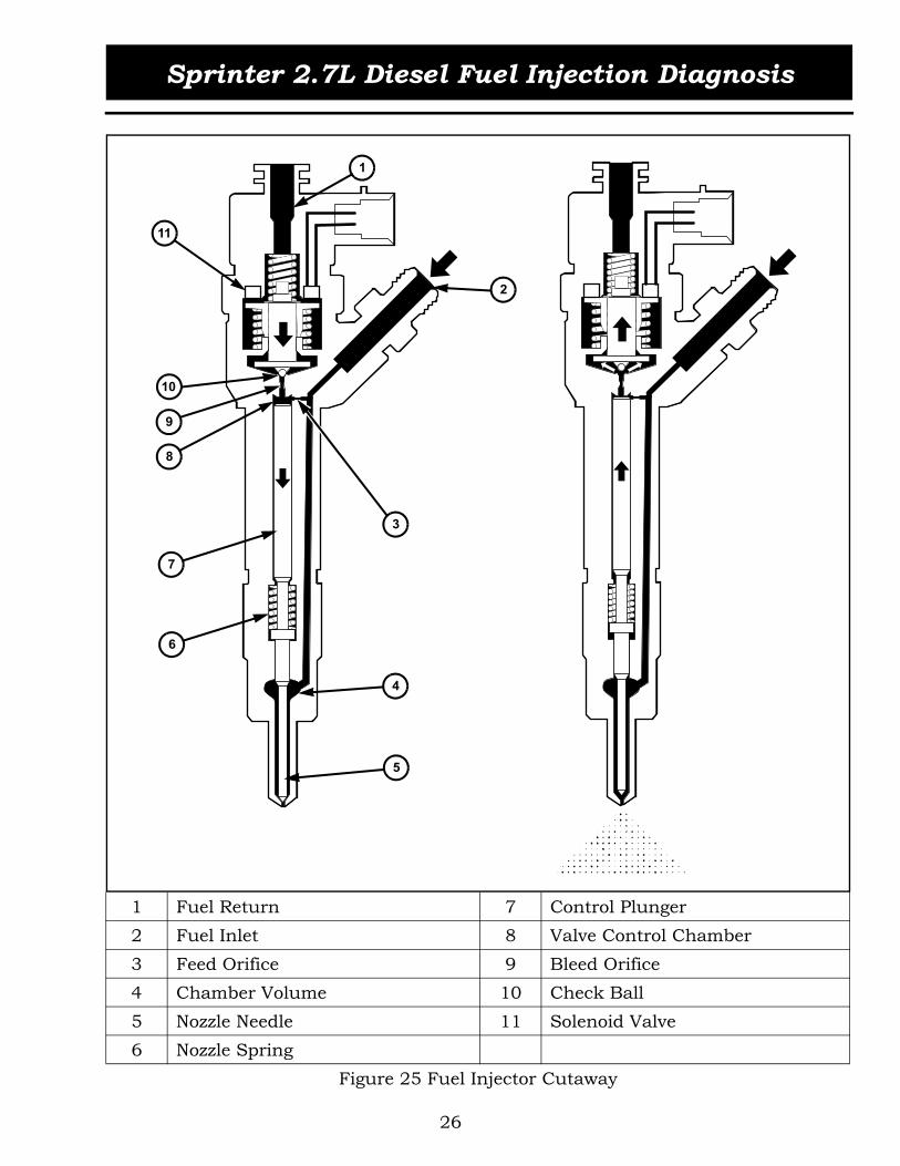
Refer to Figure 25. The fuel coming from the rail is present at the fuel inlet (2) in the valve control chamber (8) and in the chamber volume (4). The rail pressure builds up in both areas (8) and (4).The surface difference of the valve control chamber (8) compared to the chamber vol-ume (4) and the additionally acting force of the nozzle spring (6), prevent the nozzle needle (5) from opening. This condition exists when the start phase begins or if the vehicle is in the deceleration mode (engine running and high pressure pump deliver-ing).
Injector Opens (Start of Injection)
When the solenoid valve (11) is energized, the check ball (10) is attracted and over-comes the force of the valve spring. The check ball now opens the valve control cham-ber (8) and the controlled quantity of fuel is able to flow along the fuel return (1) back to the fuel tank. As a result of the pressure drop in the valve control chamber (8) the nozzle needle (5) is raised by virtue of the difference in pressure. The rate of opening of the nozzle needle depends on the cross-section of the bleed orifice (9) above the valve control chamber (8) and the feed orifice (3) positioned between high pressure feed (2) and valve control chamber.
Injector Opened Fully
The control plunger (7) reaches its upper stop where it remains supported by a cush-ion of fuel, which is generated by the flow of fuel between the bleed and feed orifices. The injector nozzle has now opened fully, and the fuel is injected into the combustion chamber at a pressure almost equal to that in the fuel rail.
Injector Closes (End of injection)
After the solenoid valve current is switched off, the valve spring pushes the check ball (10) back onto the valve seat. The bleed orifice is closed as a consequence of this and the pressure in the valve control chamber (8) rises to the level of the system pressure. The closing force which is active in the valve control chamber (8), is greater than that in the chamber volume (4), as a result of which the nozzle needle (5) closes.
Sprinter 2.7L Diesel Fuel Injection Diagnosis
26
Figure 25 Fuel Injector Cutaway
1 Fuel Return 7 Control Plunger2 Fuel Inlet 8 Valve Control Chamber3 Feed Orifice 9 Bleed Orifice4 Chamber Volume 10 Check Ball5 Nozzle Needle 11 Solenoid Valve6 Nozzle Spring
1
11
2
4
5
7
3
8
10
9
6

Sprinter 2.7L Diesel Fuel Injection Diagnosis
27
MODULE 3 ECM INPUTS
ECM output decisions are based on the inputs to the ECM. As the ECM inputs change, the ECM will change the fuel curve for optimum performance.
POWER SUPPLIES AND GROUNDS
The ECM receives a timer-controlled battery power input and three timer-controlled ignition power inputs. Timer-controlled power enables the ECM to perform key OFF diagnostics, store DTCs and reduce the vehicle’s overall current draw.
Battery voltage is supplied to the Timer Module within Fuse Block No.1 through the ignition switch when the ignition is in the START or RUN position. This ignition sense circuit is used by the Timer Module to "wake up" the ECM and also to delay the ECM power-off function.
Ground is provided to the ECM through three pins of connector No.1 to chassis ground.
It is important that the ECM have good power and ground circuits to ensure proper operation of the engine. When diagnosing an electronic control malfunction on the common rail diesel engine, it is important that the integrity of all fuses, relays, connec-tors, and grounds are checked and proper connections are made.
Figure 26 ECM Power Supplies and Grounds

Sprinter 2.7L Diesel Fuel Injection Diagnosis
28
Figure 27 Block Diagram ECM Inputs
Diagnosis (K-Line)
CAN Bus
Enhanced Accident Response
Glow Plug Circuit
Fuel Rail Pressure
Camshaft Position
Fuel Temperature
Kickdown
Cruise Control
Crankshaft Position
Mass Air Flow
Boost Pressure
Accelerator Pedal Position
Intake Air Temperature
Oil Temperature/Level/Quality
Water in Fuel
Low Fuel Pressure
Coolant Temperature
ECM
AtmosphericPressure

Sprinter 2.7L Diesel Fuel Injection Diagnosis
29
POSITION SENSORS
CRANKSHAFT POSITION SENSOR (CKP)
The crankshaft position sensor (CKP) is located opposite the teeth on the flywheel and uses a non contact method to record the position of the crankshaft. When the crank-shaft is rotating, an alternating current signal is produced. The leading edges of each tooth on the flywheel generate a positive current signal in the position sensor, while the trailing edges generate a negative current signal. The period or frequency of the signal is the time required by the crankshaft to turn through the gap between two fly-wheel teeth.
Figure 28 Crankshaft Position Sensor
OPERATION
The clearance between the CKP and the flywheel are fixed by the installation position. The flywheel toothed ring has 58 teeth, which are evenly spaced every 6°. Two teeth on the flywheel are missing (the 59th and 60th). The resulting gap is used by the ECM to detect TDC of cylinder number one. The angle between the gap and TDC of cylinder number one is 108°, or 18 teeth. The crankshaft position is calculated so that the start and end of injection can occur at the right moment. The engine speed signal is also processed by the ECM from the CKP. This signal is then broadcast to other control modules over the CAN bus.The loss of CKP signal will cause the ECM to stop triggering the injectors. The engine shuts down and will not restart.

Sprinter 2.7L Diesel Fuel Injection Diagnosis
30
Figure 29 Crankshaft Position Sensor and Flywheel Toothed Ring
When the crankshaft rotates, an alternating voltage is generated (Figure 30) in the CKP by the flywheel teeth. The front edge of a tooth generates a positive voltage pulse and the rear edge a negative voltage pulse. The distance from the positive to the nega-tive voltage peak corresponds to the length of a tooth.The gap produced by 2 missing teeth results in no voltage being generated in the CKP. This is used to detect the position of cylinder number one.
Figure 30 CKP Signal

Sprinter 2.7L Diesel Fuel Injection Diagnosis
31
Failure Modes
The ECM monitors the operation of the CKP and stores fault codes related to the fol-lowing conditions:
Crankshaft sensor plausibility 1 Crankshaft sensor plausibility 2 Crankshaft sensor over speed detection Synchronization between crankshaft and camshaft - flow limiter activated Synchronization between crankshaft and camshaft - no crankshaft signal Synchronization between crankshaft and camshaft - plausibility Synchronization between crankshaft and camshaft - main injection correction is faulty
CAMSHAFT POSITION SENSOR (CMP)
The Camshaft Position (CMP) sensor is located on top of the exhaust camshaft, at the rear of the engine near injector number 5. The CMP utilizes a non contact method on one segment of the camshaft to record the camshaft position. When the ECM receives the signal from the CMP, it can then detect TDC of cylinder number one. The signal from the camshaft sensor is only required during engine starting for synchronizing injection timing.
Figure 31 Camshaft Position Sensor

Sprinter 2.7L Diesel Fuel Injection Diagnosis
32
OPERATION
The CMP sensor consists of a Hall-effect integrated circuit, flexible printed circuit board, capacitors and a magnet (Figure 32).
Figure 32 Camshaft Position Sensor
The CMP is a 12 volt Hall-effect type sensor, with a return signal that switches from 0 to 5 volts depending on the position of the segment machined into the exhaust cam-shaft.
Figure 33 Camshaft Position Sensor Schematic

Sprinter 2.7L Diesel Fuel Injection Diagnosis
33
The signal wire of the CMP sensor is normally switched high (approximately 5 volts). When the segment machined into the exhaust camshaft is positioned opposite the CMP, the camshaft signal switches to low (approximately 0V). A low signal is used for detecting ignition TDC of cylinder 1 by the engine control module (ECM). If no signal is supplied by the camshaft position sensor, the vehicle will not start because cylinder order can not be detected (Figure 34).
Figure 34 CMP Sensor Signal
Failure Modes
The ECM monitors the operation of the CMP and stores fault codes related to the fol-lowing conditions:
Synchronization between crankshaft and camshaft - no camshaft signal Synchronization between crankshaft and camshaft - flow limiter activated Synchronization between crankshaft and camshaft - camshaft frequency signal too high
CAMSEGMENT

Sprinter 2.7L Diesel Fuel Injection Diagnosis
34
INJECTION TIMING SYNCHRONIZATION
The injection timing is synchronized by means of the signals supplied by the crank-shaft position sensor (CKP) and the camshaft position sensor (CMP). The ECM ana-lyzes both signals to detect the TDC position of cylinder number one. When the ECM detects the voltage gap resulting from the two missing teeth on the flywheel, it must also detect the low signal from the segment on the exhaust camshaft. The simulta-neous voltage gaps are an indication to the ECM that the engine is 108° BTDC of cylin-der number one.
Figure 35 Injection Timing Synchronization
1 Crankshaft Angle / Firing Order 3 CKP Signal2 Offset Angle Cylinder No. 1 4 CMP Signal

Sprinter 2.7L Diesel Fuel Injection Diagnosis
35
ACTIVITY 3.1 CAM AND CRANK SENSORS
The purpose of this activity is to familiarize the students with the engine's behavior resulting from various Cam and Crank sensor failures.
1. With the engine running, disconnect the Crank sensor and observe the result.
2. Are there any DTCs present?
YES __________________________________________________________________
NO3. What is the status of the MIL lamp?
ON
OFF4. With the sensor still disconnected attempt to start the engine. Does the engine
start?
YES
NO5. Are there any DTCs present?
YES __________________________________________________________________
NO6. What is the status of the MIL lamp?
ON
OFF7. Reconnect the Crank sensor and clear DTCs.8. With the engine running, disconnect the Cam sensor and observe the result.
9. Are there any DTCs present?
YES __________________________________________________________________
NO10. What is the status of the MIL lamp?
ON
OFF

Sprinter 2.7L Diesel Fuel Injection Diagnosis
36
11. With the sensor still disconnected attempt to start the engine. Does it start?
YES
NO12. Are there any DTCs present?
YES __________________________________________________________________
NO13. What is the status of the MIL lamp?
ON
OFF14. Explain the results of steps 1 through 13.
15. Using the appropriate service manual, determine the color and position of the Cam and Crank sensor wires at the ECM.
16. Connect a dual trace lab scope to the Cam and Crank sensor signal wires at the ECM connector and observe the relation of the two patterns with the engine run-ning.
17. With the engine running and the scope connected as in step 16, short the Cam sensor signal wire to ground and observe the results. Will the engine start under these circumstances?
YES
NO18. Connect a dual trace lab scope to the Crank sensor signal and ground wires at
the ECM connector and observe the patterns.

Sprinter 2.7L Diesel Fuel Injection Diagnosis
37
19. Perform the following tests (with the engine running) and explain the results:
Short the sensor signal wire to ground.
Short the sensor ground wire to ground.
Short the sensor ground wire to 12 Volts.
Short the sensor signal wire to 12 Volts.
Short the sensor signal and sensor ground wire together.

Sprinter 2.7L Diesel Fuel Injection Diagnosis
38
ACCELERATOR PEDAL POSITION SENSOR
The accelerator pedal position sensor is located within the accelerator pedal assembly. The driver supplies the torque requirements for the engine by operating the accelera-tor pedal in accordance with the desired speed or acceleration. The pedal sensor con-verts the mechanical operation of the pedal into an electrical signal and sends the information to the ECM. The ECM adjusts the quantity of the fuel that is injected into the engine.
The accelerator pedal position sensor is serviced as an assembly with the pedal assem-bly.
Figure 36 Accelerator Pedal Position Sensor
Operation
The Accelerator Pedal Position (APP) sensor is comprised of two variable resistors (sen-sors 1 and 2) that provide the ECM with redundant voltage signals (Figure 37). As the position of the accelerator pedal changes, the resistance of the sensor changes. The ECM sends a 5 volt reference signal to the APP sensor and the APP sensor returns two variable voltage signals. The voltage signal increases in direct proportion to the depressing of the pedal. The voltage signal from sensor 2 is always half the value of sensor 1 (Figure 38). The signal of sensor 1 ranges from 0.2 to 4.7 volts, while the sen-sor 2 signal ranges from 0.1 to 2.4 volts.
The voltage value cannot be read with the DRB III scan tool. The APP value is dis-played in percentage (0-100%).

Sprinter 2.7L Diesel Fuel Injection Diagnosis
39
Figure 37 APP Sensor Schematic
Failure Modes
The ECM monitors the operation of the APP and stores fault codes related to the fol-lowing conditions:
Sensor 1 signal voltage too low Sensor 1 signal voltage too high Sensor 1 supply voltage too high or too low Sensor 1 plausibility 1 Sensor 1 plausibility 2 Sensor 1 plausibility 3 Sensor 2 signal voltage too low Sensor 2 signal voltage too high Sensor 2 supply voltage too high or too low Sensor 2 circuit implausibility, potentiometer 1 and 2
Substitute Values
An APP value of 0% will be displayed under the following circumstances, regardless of the pedal position:
Short circuit to ground of the signal wire Open circuit in the signal wire Short circuit to ground of the 5V supply

Sprinter 2.7L Diesel Fuel Injection Diagnosis
40
Open circuit of the 5V supplyIf there is an open circuit of the ground wire, the actual value displayed is 100%
Figure 38 APP Sensor Signal (Approximate Values)
0
0.5
1
1.5
2
2.5
3
3.5
4
4.5
5
0% 100%
VOLTS
THROTTLE POSITION
APP1
APP2

Sprinter 2.7L Diesel Fuel Injection Diagnosis
41
ACTIVITY 3.2 ACCELERATOR PEDAL ACTIVITY
The purpose of this activity is to gain an understanding of the accelerator pedal posi-tion sensor and kickdown switch.
ACCELERATOR PEDAL POSITION SENSOR
1. Connect DRB III to vehicle and access engine, sensors.2. What information is available for display with regards to the accelerator pedal
position sensors?
3. With the key on engine off slowly press the accelerator pedal to W.O.T. What do you notice about the percentages shown for APP1 and APP2 on the DRB III versus pedal feel and physical position?
4. Compared to pedal travel when do both APPs reach 100%?
5. How many circuits are there on the APP's and what are their functions? List below.
6. Using the proper service information locate the two signal wires on the APP sensor and backprobe.
7. With the key on engine off what is the voltage range throughout APP's pedal travel?APP1: WOT ________ Idle ________ APP2: WOT ________ Idle ________
8. Is there a procedure to adjust the APP's?
KICKDOWN SWITCH
1. Connect the DRB III to the vehicle and access Transmission, inputs/outputs.

Sprinter 2.7L Diesel Fuel Injection Diagnosis
42
2. What information is available for display regarding the kick down switch? Record below.
3. What is this input used for?
4. Is there a procedure to adjust the KDS?

Sprinter 2.7L Diesel Fuel Injection Diagnosis
43
PRESSURE SENSORS
BOOST PRESSURE SENSOR
The boost pressure sensor is mounted to the charge air pipe (Figure 39). The sensor allows the ECM to monitor intake air downstream of the turbocharger.
Figure 39 Boost Pressure Sensor Location
The boost pressure sensor is a three-wire sensor with a sensing pressure port on the bottom. The pressure port is inserted into the charge air pipe through an access hole. An O-ring provides the sealing once the sensor is mounted to the charge air pipe (Fig-ure 40). The ECM uses boost pressure combined with intake air temperature to deter-mine the volume of air entering the engine.
Figure 40 Boost Pressure Sensor

Sprinter 2.7L Diesel Fuel Injection Diagnosis
44
OPERATION
The boost pressure sensor consists of piezoresistive elements attached to a measuring diaphragm. The resistance value changes when stress is applied to the diaphragm. The resistors form a measuring bridge, so that when the diaphragm moves the bridge balance is changed. The bridge voltage is a measure for the boost presssure.
The sensor receives a 5-volt reference from the ECM. Sensor ground is also provided by the ECM. The bridge voltage varies from 0.5 to 4.5 volts depending on boost pres-sure.
Figure 41 Boost Pressure Sensor Schematic
As boost pressure increases, the boost signal voltage also increases. If the engine is not running, the value sent to the ECM is equal to the atmosphericpressure. The boost pressure operating range is from 0 to 2.5 bar (0 to 36.25 psi).

Sprinter 2.7L Diesel Fuel Injection Diagnosis
45
Figure 42 Boost Pressure Sensor Signal (Approximate Values)
Failure Modes
If the boost pressure sensor fails, the ECM records a DTC into memory and continues to operate the engine in limp-in mode. When the ECM is operating in this mode, a loss of power will be present, as if the turbocharger was not operating.
The ECM monitors the operation of the boost pressure sensor and stores fault codes related to the following conditions:
Signal voltage too low Signal voltage too high Supply voltage too high or too low
Substitute Values
If the sensor ground wire has an open circuit, the actual value displayed is 38.29 psi If the signal wire has a short circuit to ground or open circuit, the substitute value is 2.90 psi If the 5-volt power supply has a short circuit to ground or open circuit, the sub-stitute value is 2.90 psi
0
0.5
1
1.5
2
2.5
3
3.5
4
4.5
5
0.2 1 2.5
BOOST PRESSURE IN BAR (PSI)
VOLTS
(2.9) (14.5) (36.2)
Sprinter 2.7L Diesel Fuel Injection Diagnosis
46
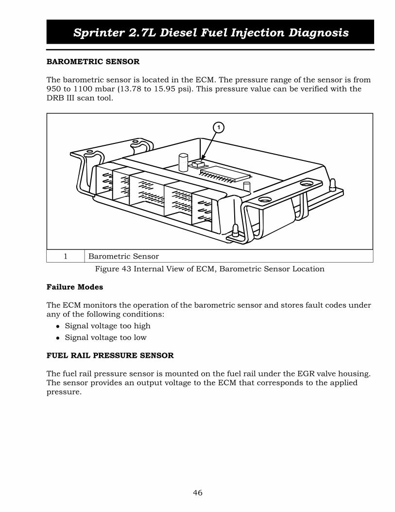
BAROMETRIC SENSOR
The barometric sensor is located in the ECM. The pressure range of the sensor is from 950 to 1100 mbar (13.78 to 15.95 psi). This pressure value can be verified with the DRB III scan tool.
Figure 43 Internal View of ECM, Barometric Sensor Location
Failure Modes
The ECM monitors the operation of the barometric sensor and stores fault codes under any of the following conditions:
Signal voltage too high Signal voltage too low
FUEL RAIL PRESSURE SENSOR
The fuel rail pressure sensor is mounted on the fuel rail under the EGR valve housing. The sensor provides an output voltage to the ECM that corresponds to the applied pressure.
1 Barometric Sensor
1

Sprinter 2.7L Diesel Fuel Injection Diagnosis
47
Figure 44 Fuel Rail Pressure Sensor
OPERATION
The fuel rail pressure sensor consists of a high-grade spring steel diaphragm with an attached strain gage. The deflection of the diaphragm changes the resistance of the strain gage. The sensor measures the current fuel rail pressure and sends a voltage signal to the ECM. The ECM then actuates the fuel rail pressure solenoid until the desired rail pressure is achieved. If the rail pressure sensor fails, the engine will run in limp-in mode. The pressure actual value ranges from 200 to 1350 bar (2,900 to 20,000 psi).
Figure 45 Fuel Rail Pressure Sensor Construction

Sprinter 2.7L Diesel Fuel Injection Diagnosis
48
The ECM uses the fuel rail pressure input to control the output of the fuel pressure solenoid. The ECM sends a 5 volt supply to the fuel rail pressure sensor. Depending on the fuel rail pressure, the sensor output signal varies from 0.5 to 4.5 volts (Figure 47).
Figure 46 Fuel Rail Pressure Sensor Schematic
Failure Modes
The ECM monitors the operation of the fuel rail pressure sensor and stores fault codes under any of the following conditions:
Voltage too high Voltage too low Voltage too high or too low Plausibility between fuel rail pressure sensor and fuel pressure solenoid Maximum pressure has been exceeded Rail pressure too low No pressure build up. Fuel pressure solenoid open Fuel pressure solenoid stuck in closed position Fuel pressure leakage detected Control deviation engine speed too high
Substitute Values
If the sensor signal wire has a short circuit to ground, the actual value displayed is 0.000 psi If the sensor 5V supply wire has a short circuit to ground, the actual value dis-played is 228.9 bar (3321.233 psi) If the sensor has an open circuit in a wire, the actual value displayed is 1499.9 bar (21754.799 psi)
FUEL RAIL
FUEL RAIL
Sprinter 2.7L Diesel Fuel Injection Diagnosis
49
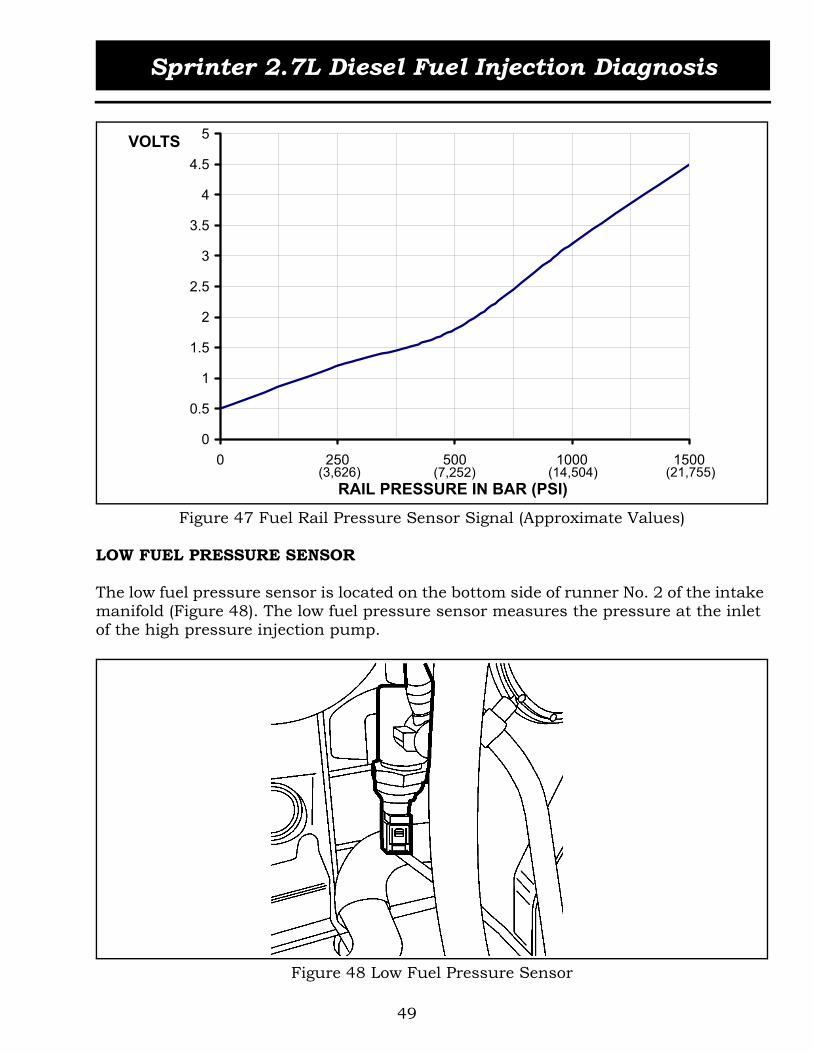
Figure 47 Fuel Rail Pressure Sensor Signal (Approximate Values)
LOW FUEL PRESSURE SENSOR
The low fuel pressure sensor is located on the bottom side of runner No. 2 of the intake manifold (Figure 48). The low fuel pressure sensor measures the pressure at the inlet of the high pressure injection pump.
Figure 48 Low Fuel Pressure Sensor
0
0.5
1
1.5
2
2.5
3
3.5
4
4.5
5
0 250 500 1000 1500
RAIL PRESSURE IN BAR (PSI)
VOLTS
(3,626) (7,252) (14,504) (21,755)

Sprinter 2.7L Diesel Fuel Injection Diagnosis
50
Operation
The ECM sends a 5 volt supply to the low fuel pressure sensor. Depending on the fuel pressure, the sensor output signal varies from 0.5 to 3.5 volts.
Figure 49 Low Fuel Pressure Sensor Schematic
When the engine is idling, the low fuel pressure is approximately 2.5 bar (36.26 psi). Once the engine reaches governed speed the pressure is between 3.5 and 4 bar (50.76 and 58.01 psi).
Figure 50 Low Fuel Pressure Sensor Signal (Approximate Values)
LOW FUEL
PRESSURE SENSOR
LOW FUEL
PRESSURE SIGNAL
0
0.5
1
1.5
2
2.5
3
3.5
4
0 2.8 2.9 3.0 3.1 3.7(40.5) (42.5) (44.5) (45) (53)
FUEL PRESSURE IN BAR (PSI)
VOLTS

Sprinter 2.7L Diesel Fuel Injection Diagnosis
51
Failure Modes
The ECM monitors the operation of the low fuel pressure sensor and stores fault codes under any of the following conditions:
Signal voltage too low Signal voltage too high Plausibility Fuel delivery pressure too small Actual pressure differs from the specified pressure (delivery plausibility) Minimum pressure at engine start not reached Fuel filter restriction
If the ECM detects a restriction in the fuel filter, it will transmit a signal to the instru-ment cluster via the CAN bus. The instrument cluster illuminates the fuel filter clogged indicator lamp to alert the driver (Figure 51).
Figure 51 Filter Clogged Indicator Lamp

Sprinter 2.7L Diesel Fuel Injection Diagnosis
52
TEMPERATURE SENSORS
INTAKE AIR TEMPERATURE SENSOR (IAT)
The inlet air temperature (IAT) sensor is mounted to the charge air pipe. The IAT is a two-pin sensor, which consists of an NTC resistor in a plastic housing. The IAT is locked in place by two retaining clips and sealed with an O-Ring (Figure 52).
Figure 52 Inlet Air Temperature Sensor
Operation
The NTC resistor located within the IAT changes its resistance in line with the charge air temperature. The ECM sends 5 volts to the NTC resistor and grounds it through the sensor return line. The ECM interprets the voltage as air temperature.

Sprinter 2.7L Diesel Fuel Injection Diagnosis
53
Figure 53 IAT Sensor Schematic
The IAT temperature value ranges from -40°C to 150°C (-40°F to 302°F). If the engine is cold, the IAT actual value equals the ambient temperature.
Figure 54 IAT Sensor Resistance Chart (Approximate Values)
0
1000
2000
3000
4000
5000
6000
7000
20 60 90 120(68) (140) (194) (248)
INLET AIR TEMPERATURE IN ºC (ºF)
OHMS

Sprinter 2.7L Diesel Fuel Injection Diagnosis
54
Failure Modes
The ECM monitors the operation of the inlet air temperature sensor and stores fault codes under any of the following conditions:
Signal voltage too high Signal voltage too low
Substitute Values
If the signal wire is shorted to ground, the actual value displayed is 150°C (302°F) If the signal wire is shorted to positive, the actual value displayed is -40° and the fuel temperature displayed is also -40° If the signal wire has an open circuit, the actual value displayed is -40°
COOLANT TEMPERATURE SENSOR
The engine coolant temperature sensor (ECT) is a two-pin sensor located in the ther-mostat housing. The sensor consists of a plastic housing, which contains an NTC resistor. The ETC is locked in place by a locking spring and sealed with an O-Ring.
Figure 55 Coolant Temperature Sensor
Operation
The ECM sends 5 volts to the NTC resistor and grounds it through the sensor return line. The ECM determines the coolant temperature based on the voltage drop within the sensor circuit and changes the fuel supply accordingly.

Sprinter 2.7L Diesel Fuel Injection Diagnosis
55
Figure 56 ECT Sensor Schematic
If the engine is cold, the ECT actual value is equal to the ambient temperature.
Failure Modes
The ECM monitors the operation of the coolant temperature sensor and stores fault codes under any of the following conditions:
Signal voltage too high Signal voltage too low Operating temperature not reached
Substitute Values
If the signal wire is shorted to ground, the actual value displayed is 130°C (266°F) If the signal wire is shorted to positive, the actual value displayed is -40° If a wire has an open circuit, the actual value displayed is -40°
TEMPERATURE (ECT)

Sprinter 2.7L Diesel Fuel Injection Diagnosis
56
Figure 57 ECT Sensor Resistance Chart (Approximate Values)
FUEL TEMPERATURE SENSOR
The fuel temperature sensor is located in the fuel return line directly downstream of the fuel pressure solenoid (Figure 58). The sensor measures the temperature of the fuel in the return pipe between the fuel rail and the pre-heating valve.
Figure 58 Fuel Temperature Sensor
0
500
1000
1500
2000
2500
3000
3500
20 40 60 80 100(68) (104) (140) (176) (212)
COOLANT TEMPERATURE IN ºC (ºF)
OHMS

Sprinter 2.7L Diesel Fuel Injection Diagnosis
57
The sensor ranges from - 40°C (-40°F ) to 140°C (284°F). If the engine is cold, the actual value sent will read ambient temperature. The value rises after the engine has been started. A pumping element of the high pressure fuel injection pump is switched of if fuel temperature has reached approximately 110°C (230°F) and engine speed is above 2000 RPM.
Figure 59 Fuel Temperature Sensor Resistance Chart (Approximate Values)
Failure Modes
The ECM monitors the operation of the fuel temperature sensor and stores fault codes under any of the following conditions:
Signal voltage too high Signal voltage too low
Substitute Values
If the signal wire is shorted to ground, the actual value displayed is 140°C (284°F) If the signal wire is shorted to positive, the actual value displayed is -40°. The intake temperature value displayed is also -40° If a wire has an open circuit, the actual value displayed is -40°
0
500
1000
1500
2000
2500
3000
3500
20 40 60 80 100(68) (104) (140) (176) (212)
FUEL TEMPERATURE IN ºC (ºF)
OHMS
Sprinter 2.7L Diesel Fuel Injection Diagnosis
58
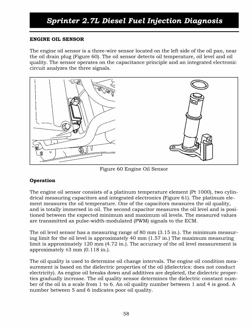
ENGINE OIL SENSOR
The engine oil sensor is a three-wire sensor located on the left side of the oil pan, near the oil drain plug (Figure 60). The oil sensor detects oil temperature, oil level and oil quality. The sensor operates on the capacitance principle and an integrated electronic circuit analyzes the three signals.
Figure 60 Engine Oil Sensor
Operation
The engine oil sensor consists of a platinum temperature element (Pt 1000), two cylin-drical measuring capacitors and integrated electronics (Figure 61). The platinum ele-ment measures the oil temperature. One of the capacitors measures the oil quality, and is totally immersed in oil. The second capacitor measures the oil level and is posi-tioned between the expected minimum and maximum oil levels. The measured values are transmitted as pulse-width-modulated (PWM) signals to the ECM.
The oil level sensor has a measuring range of 80 mm (3.15 in.). The minimum measur-ing limit for the oil level is approximately 40 mm (1.57 in.) The maximum measuring limit is approximately 120 mm (4.72 in.). The accuracy of the oil level measurement is approximately ±3 mm (0.118 in.).
The oil quality is used to determine oil change intervals. The engine oil condition mea-surement is based on the dielectric properties of the oil (dielectrics: does not conduct electricity). As engine oil breaks down and additives are depleted, the dielectric proper-ties gradually increase. The oil quality sensor determines the dielectric constant num-ber of the oil in a scale from 1 to 6. An oil quality number between 1 and 4 is good. A number between 5 and 6 indicates poor oil quality.

Sprinter 2.7L Diesel Fuel Injection Diagnosis
59
Figure 61 Engine Oil Sensor
The engine oil sensor constantly supplies data to the ECM in the form of information blocks (Figure 62). Each information block consists of three successive square wave signals of 100 ms each, followed by a synchronization pause of 1 second + 200 ms. A measured variable is assigned to each square-wave signal (A, B, C). The values are determined by the ON/OFF ratio, which ranges from 19 to 81%.
Refer to the examples shown in Figure 62. The first information block (1) contains square wave signals which fall between the 20-80% window. The values for oil temper-ature (60%), oil level (50%) and oil quality (30%) are in order.
The second information block (2) contains square wave signals with ON/OFF ratios above 80%. The oil temperature signal (81%) indicates a temperature higher than 160°C (320°F), the oil level signal (80%) indicates an oil level higher than 80 mm (3.15 in.), and the oil quality (81%) indicates good oil quality.
The third information block (3) contains square wave signals with ON/OFF ratios below 20%. The oil temperature signal (19%) indicates a temperature lower than -40°C, the oil level signal (19%) indicates an oil level lower than 0 mm, and the oil qual-ity (15%) indicates poor oil quality.
1 Oil Level Sensor 5 Electronic Circuit2 Oil Quality Sensor 6 Start of Measuring Range3 Oil Temperature Sensor 7 End of Measuring Range4 Electrical Connector
80mm(3.15 in)
40mm(1.57 in)3
6
7
2
1
4
5

Sprinter 2.7L Diesel Fuel Injection Diagnosis
60
Figure 62 Engine Oil Sensor Information Block
If the engine is cold, the oil temperature actual value is equal to the ambient tempera-ture actual value. The actual value rises after the engine has been started.
Failure Modes
The ECM monitors the operation of the oil sensor and stores fault codes under any of the following conditions:
Synchronization pause error Wire open or shorted to ground Supply voltage too high or too low Timing error Oil level plausibility Oil quality plausibility Water contamination
A Oil Temperature Signal 1 On/Off Ratio Between 20-80%B Oil Level Signal 2 On/Off Ratio > 80%C Oil Quality Signal 3 On/Off Ratio < 20%T Time Period

Sprinter 2.7L Diesel Fuel Injection Diagnosis
61
Substitute Values
An oil temperature actual value of 70°C (158°F) will be displayed under the following circumstances:
Signal wire is shorted to ground 5-volt supply wire is shorted to ground Open circuit in any wire
An oil quality actual value of 2550000 will be displayed under the following circum-stances:
Signal wire is shorted to ground 5-volt supply wire is shorted to ground Open circuit in any wire
An oil level actual value of 254999 mm (100393.50 in.) will be displayed under the fol-lowing circumstances:
Signal wire is shorted to ground 5-volt supply wire is shorted to ground Open circuit in any wire

Sprinter 2.7L Diesel Fuel Injection Diagnosis
62
SWITCH INPUTS
KICK-DOWN SWITCH
The kickdown switch is located on the accelerator pedal assembly and consists of a spring loaded electric switching contact. The switch influences the shift program of the electronic transmission control.When the kickdown switch is actuated via the accelerator pedal, a CAN bus signal is sent from the ECM to the TCM. The TCM processes the information and controls the downshifting of the automatic transmission.
Figure 63 Kick-Down Switch
SPEED CONTROL SWITCH
The speed control switch is located behind the steering wheel. At vehicle speeds above 25 MPH, the switch activates the speed control function integrated in the ECM. The ECM is supplied with the following inputs for speed control operation:
Vehicle speed signal from the CAB module Park/Neutral signal from the TCM Stop lamp switch

Sprinter 2.7L Diesel Fuel Injection Diagnosis
63
Figure 64 Speed Control Switch Location
The speed control lever can be moved in four different directions (up/down and for-ward/back) to select the desired setting. The lever knob is labeled to identify the speed control functions (Figure 65).
Figure 65 Speed Control Switch
1 Set/Accelerate Speed 3 Off2 Set/Decelerate Speed 4 Resume Set Speed

Sprinter 2.7L Diesel Fuel Injection Diagnosis
64
Operation
The speed control lever is comprised of five sets of contacts. Two switch contacts oper-ate simultaneously when the cruise control lever is actuated. One contact provides the actual input while a safety contact provides a verification input to the ECM. The safety contact must close at the same time for the selected input to be accepted by the ECM and recognized as an intentional action on the part of the driver (Figure 66).
Figure 66 Speed Control Switch Schematic
Failure Modes
The ECM monitors the operation of the speed control switch and stores fault codes under any of the following conditions:
Negative acceleration deviation Positive acceleration deviation Control contact alone No verification contact Speed control signals through CAN are implausible Operating unit has contact short (two contacts synchronous)
12 V OL T S UP P L YS P E E DC ONT R OLS WIT C H
E NG INEC ONT R OLMODUL E(E C M)
R E S UME S IG NA L
DE C E L /S E T S IG NA L
V E R IF IC A T ION S IG NA L
ON/OF F S IG NA L
A C C E L /S E T S IG NA L

Sprinter 2.7L Diesel Fuel Injection Diagnosis
65
MASS AIR FLOW SENSOR(MAF)
The Mass Air Flow (MAF) Sensor is located in the air intake duct between the air filter and the turbocharger (Figure 67). The MAF sensor uses semiconductor technology throughout, and is used to calculate the air mass flowing past it per time unit.
Figure 67 MAF Location
OPERATION
The ECM uses the mass air flow (MAF) sensor to measure air density. Refer to Figure 68. The temperature resistor (2) located at the front of the MAF sensor measures the temperature of the inlet air. By varying the voltage, the electronic circuit regulates the temperature of the heating resistor (1) in the rear so that it is 160°C (320°F) higher than the temperature of the intake air. The temperature at the heating resistor is mea-sured by a sensing resistor in-between (3).
Because the incoming air has a cooling effect, the greater the amount of air that flows in, then the higher the voltage of the heating resistor (1). The heating resistor is there-fore a measure of mass of air flowing past.
If a temperature change occurs as a result of an increase or reduction of air flow, the ECM corrects the voltage at the heating resistor until the temperature difference is again achieved. This control voltage is use by the ECM as a unit measure for metered air mass.

Sprinter 2.7L Diesel Fuel Injection Diagnosis
66
Figure 68 Mass Air Flow Sensor
The ECM supplies the MAF sensor with two separate voltage levels. One circuit pro-vides 12 volts and the other 5 volts. The ECM also provides the ground to the MAF.
Figure 69 MAF Sensor Schematic
1 Heating Resistor 3 Sensing Resistor2 Temperature Resistor
1 2
3

Sprinter 2.7L Diesel Fuel Injection Diagnosis
67
The measured air mass value is sent to the ECM as a control voltage that ranges from approximately 1 to 4.5 volts (Figure 70).
Figure 70 MAF Sensor Signal (Approximate Values)
Failure Modes
The ECM monitors the operation of the MAF sensor and stores fault codes under any of the following conditions:
Signal voltage too low Signal voltage too high Supply voltage too high or too low Plausibility
WATER IN FUEL SENSOR (WIF)
The WIF sensor is located on the bottom of the fuel filter. The WIF is a three-wire sen-sor within a plastic housing. The sensor is inserted into the access hole and turned 90 degrees to lock it in place. An O-Ring seals the sensor housing in the filter.
0
0.5
1
1.5
2
2.5
3
3.5
4
4.5
5
0 15 60 370 480
MASS AIR FLOW IN KG/HR
VOLTS

Sprinter 2.7L Diesel Fuel Injection Diagnosis
68
Figure 71 Water in Fuel Sensor
Operation
Diesel fuel does not provide any electrical contact between the sensor probes. Battery voltage is present in the WIF sensing circuit when the ignition is ON. When water is present in the system, the conducting properties of the water allow the sensor probes to close the electrical circuit. The digital integrated circuit senses the ground and pulls the WIF sensing circuit down to 0 volts after a time delay of approximately 9 seconds.
Figure 72 WIF Sensor Schematic
When the ECM senses 0 volts in the WIF signal circuit, it signals the instrument clus-ter via the CAN bus to illuminate the WATER IN FUEL indicator lamp.
S E NS ORG R OUND
12V
WA T E RIN F UE L (WIF )
S E NS OR
E NG INEC ONT R OLMODUL E(E C M)
WIFS IG NA L
12V S UP P L Y40K

Sprinter 2.7L Diesel Fuel Injection Diagnosis
69
Figure 73 WIF Indicator Lamp
Failure Modes
The ECM monitors the WIF sensor signal and stores a single fault code, which could indicate any of the following conditions:
Water in fuel filter, or sensor malfunction, or short to ground, or short to posi-tive, or open circuit in any of the wires
GLOW PLUG MODULE
The glow plug module is located in the engine compartment under the battery tray. The module integrates diagnostics and an electronic system that processes the input signals from the ECM for glow plug activation.
Figure 74 Glow Plug Module

Sprinter 2.7L Diesel Fuel Injection Diagnosis
70
The glow plug module monitors the operation of the glow plugs and continuously informs the ECM via a PWM signal about the operating state (glow plugs ON/OFF), and the presence of any system faults.
Figure 75 Glow Plug Module Schematic
A voltage comparator circuit monitors the PTC properties of the glow plugs and com-pares it to the voltage drop across the shunt resistors for diagnostic purposes. A short or open circuit at the glow plugs affects the voltage drop in the resistor circuit. The comparator triggers a signal if a threshold voltage of 8 mV is exceeded.
1 Glow Plug 3 Relay2 Voltage Comparator 4 Shunt Resistors
1
2
3
4

Sprinter 2.7L Diesel Fuel Injection Diagnosis
71
Fault Recognition
The following faults are recognized by the glow plug module and transmitted to the ECM:
Open circuit at one or more glow plugs Short circuit in a glow plug circuit Internal relay fault
The ECM stores a fault code when it receives an open glow plug circuit message from the glow plug module. The ECM will also activate the preglow indicator lamp in the instrument cluster for about one minute once the engine is running. If the message received by the ECM is related to a short circuit, or a communication fault, it will store a fault code and immediately activate the preglow indicator lamp. The lamp will remain activated until the fault is no longer current or the ignition is switched off.
ACM ENHANCED ACCIDENT RESPONSE INPUT
The ACM enhanced accident response input is received by the ECM in the event of an accident where the airbags have deployed. A hardwire signal from the ACM is sent to the ECM and CTM simultaneously (Figure 76).
Figure 76 ACM Enhanced Accident Response Input
The enhanced accident response input signal consists of a 12 volt, 50 millisecond pulse generated by the ACM during airbag deployment. Upon receipt of this input, the ECM shuts the engine down. The engine can be restarted again if necessary.
50 msP UL S E
E NG INEC ONT R OLMODUL E(E C M)
A IR B A GC ONT R OLMODUL E(A C M)
C E NT R A LT IME RMODUL E(C T M)
E NG INES HUT DOWNC OMMA ND
DOOR SUNL OC K E DC OMMA ND

Sprinter 2.7L Diesel Fuel Injection Diagnosis
72
Figure 77 Enhanced Accident Response ACM Input Signal
12 VOLTS(BATTERY)
50ms

Sprinter 2.7L Diesel Fuel Injection Diagnosis
73
INDIRECT INPUTS
CAN BUS INPUTS
In addition to the hardwired inputs, the ECM receives data from other control modules through the CAN bus.
Figure 78 CAN Inputs
Circuit 61 (D+)Air Conditioning InstalledMPH Instead of KM/HRSpeedometer CalibrationAmbient Air Temperature
IC
A/C Compressor Switched ONRefrigerant PressureAT
C
Transmit Answer - Valid TransponderStart Enable
SKR
EEM
Shift Lever Position
SLA
Brake Light SwitchWheel SpeedsReduction of Engine Specified TorqueCruise Control OFF
CAB
Requested Engine TorqueTorque Converter Clutch StatusLimp Home ModeEngine Emergency ShutdownKickdown AcknowledgeExcess Transmission Temperature
TCM
ECM
Con
trol
Mod
ule
INFORMATION INPUT - CAN BUS

Sprinter 2.7L Diesel Fuel Injection Diagnosis
74
ACTIVITY 3.3 ENGINE SENSORS
The purpose of this activity is to familiarize the students with the engine's behavior resulting from various sensor failures
1. Disconnect the following sensors and observe the details as indicated.
Fuel Temp Sensor:
Does the engine run? YES NO
Is the MIL lamp ON ? YES NO
Engine maximum RPM: _____________________________________________________DTCs: _______________________________________________________________________Value displayed on DRB: ____________________________________________________
Coolant Temp Sensor:
Does the engine run? YES NO
Is the MIL lamp ON ? YES NO
Engine maximum RPM: _____________________________________________________DTCs: _______________________________________________________________________Value displayed on DRB: ____________________________________________________
Low Fuel Pressure Sensor:
Does the engine run? YES NO
Is the MIL lamp ON ? YES NO
Engine maximum RPM: _____________________________________________________DTCs: _______________________________________________________________________Value displayed on DRB: ____________________________________________________
Oil Temp Sensor:
Does the engine run? YES NO
Is the MIL lamp ON ? YES NO
Engine maximum RPM: _____________________________________________________DTCs: _______________________________________________________________________Value displayed on DRB: ____________________________________________________
Sprinter 2.7L Diesel Fuel Injection Diagnosis
75
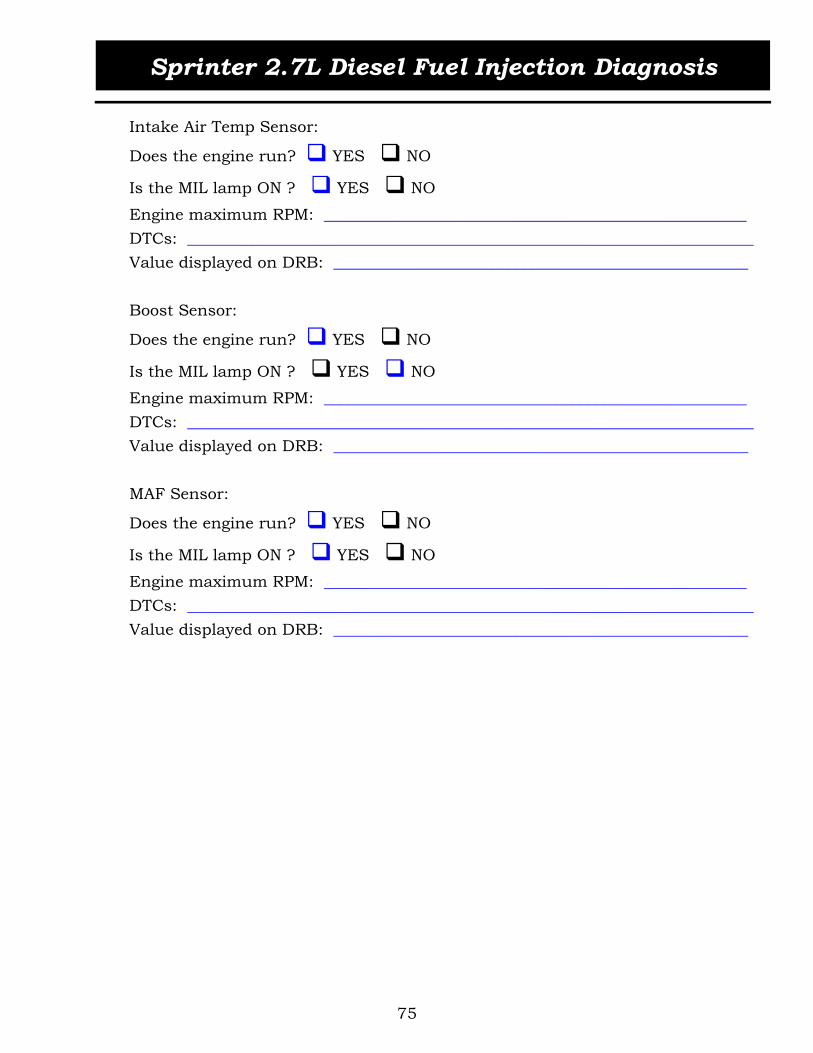
Intake Air Temp Sensor:
Does the engine run? YES NO
Is the MIL lamp ON ? YES NO
Engine maximum RPM: _____________________________________________________DTCs: _______________________________________________________________________Value displayed on DRB: ____________________________________________________
Boost Sensor:
Does the engine run? YES NO
Is the MIL lamp ON ? YES NO
Engine maximum RPM: _____________________________________________________DTCs: _______________________________________________________________________Value displayed on DRB: ____________________________________________________
MAF Sensor:
Does the engine run? YES NO
Is the MIL lamp ON ? YES NO
Engine maximum RPM: _____________________________________________________DTCs: _______________________________________________________________________Value displayed on DRB: ____________________________________________________

Sprinter 2.7L Diesel Fuel Injection Diagnosis
76
ACTIVITY 3.4 CRUISE CONTROL SWITCH
The purpose of this activity is to gain an understanding of the operation of the cruise control switch.
1. Connect DRB III to vehicle and access Engine.2. Actuate/Press the cruise control stalk. Record your findings below.
Position: _______ ACC: _______ Safety Contact: _______Position: _______ DEC: _______ Safety Contact: _______Position: _______ RES: _______ Safety Contact: _______Position: _______ OFF: _______ Safety Contact: _______
3. How does the ECM determine a fault, or an unintentional actuation?

Sprinter 2.7L Diesel Fuel Injection Diagnosis
77
MODULE 4 ECM CONTROL AND OUTPUTS
ENGINE CONTROL MODULE (ECM)
The engine control module (ECM) is located on the left hand side, under the instru-ment panel (Figure 79).
Figure 79 ECM Control Module Location
The ECM has a metal housing. The inputs, outputs, power supply and grounds are connected to the ECM through five plug-in connectors. The ECM provides different ref-erence voltage levels to input and output components through two regulated 5-volt power supplies and a 12-volt power supply (Figure 80).
A microprocessor uses control algorithms to process the input signals and calculates the injected fuel based on stored maps. The microprocessor triggers the driver stages for switching the output components.
The ECM contains the following data storage elements:
Flash EPROM—stores engine-specific curves, engine-management maps, and variant coding (engine and equipment options). EEPROM—stores SKREEM data, calibration and manufacturing data, adaptation values, operational faults and variant coding. RAM—stores variable data such as calculations data and input values.

Sprinter 2.7L Diesel Fuel Injection Diagnosis
78
Figure 80 ECM Internal Block Diagram
OPERATION/CONTROL STRATEGIES
Total quantity control function
The ECM will calculate each cylinder’s pre-injection and the main injection quantities.
The following parameters are calculated for computing the correct injected quantity: Rail specified pressure Start of injector actuation Duration of actuation
In addition, individual functions are used for total quantity control: Start quantity control Idle speed control 650 rpm Full load quantity control (reduction of injected quantity) Smooth engine running control Limiting maximum engine speed 4200 rpm Inertia fuel shutoff (interruption of fuel injection at engine speed greater than 1500 rpm and accelerator pedal not operated). This function will provide engine braking.
INPUTS
CAN BUS
RAM
EEPROM
EPROM
SignalProcessing
Microprocessor DriverStages
OUTPUTS
K-LINE
Flash
VoltageRegulation
12-VOLT SUPPLY
ENGINE
CONTROL
MODULE
(ECM)
5-VoltRef. B
5-VoltRef. A
SENSORFEED
5-VOLT
SENSORFEED
5-VOLT
SENSORFEED
12-VOLT
OUTPUTFEED
12-VOLT

Sprinter 2.7L Diesel Fuel Injection Diagnosis
79
The start of injection and the duration of injection are defined during the calculation of preinjection and main injection quantity.
Injection pressure control
The fuel pressure solenoid is used for controlling rail pressure based on the signal on/off ratio supplied by the ECM. The control loop is completed at the ECM with the aid of the rail pressure sensor, which supplies the actual rail pressure. A set value is determined on the basis of the operating point, this being adjusted by the atmospheric pressure, coolant temperature and intake air temperature.
Start quantity control
Start of fuel injection is enabled after the ECM has completed synchronization of the injection timing based on cam and crank position. The injected quantity at engine speeds less than 600 rpm is controlled by the start quantity control regardless of the accelerator pedal position. The coolant temperature sensor plays the most important part within this range: the higher the coolant temperature, the smaller the start fuel quantity.
Smooth engine running control
Irregularities in engine speed are corrected by varying the quantities injected at the specific cylinders, ensuring smooth engine running with minimum vibration. The smooth engine running control is switched off at engine speeds greater than 1500 rpm.
Injector correction quantity
The ECM compensates for dynamic injector variation by reducing or increasing the injected quantity by approximately 0.5 cubic centimeters per stroke. The injector cor-rection quantity is only active up to engine speeds of 1500 rpm.
Ignition ON strategy
The ECM supplies the signal for preglowing to the glow plug relay and initiates data interchange with the SKREEM module for drive authorization.
Starter control strategy
For starter operation the following conditions must be met: Drive authorization system released Key moved briefly into start position Engine speed: 0 rpm Selector lever position: P or N

Sprinter 2.7L Diesel Fuel Injection Diagnosis
80
Idle speed control strategy
The following signals are required for the idle speed control: Crankshaft position sensor Coolant temperature sensor Control and operating module automatic air conditioning Pedal value sensor Rail pressure sensor The idle speed is dependent on the ambient temperature and the atmospheric pressure.
Example: idle speed at 20°C (68°F) and 1000 mbar (29.5 inHg) = 680 rpm idle speed at -30°C (-22°F) and 700 mbar (20.7 inHg) = 1100 rpm
Engine stop control strategy
When turning the ignition key in the OFF position, the ECM identifies a voltage drop at circuit 15 (ignition ON). The ECM will then no longer actuate the injectors. The func-tion of the fuel pressure solenoid is checked by briefly opening the fuel pressure sole-noid when the engine is switched off. The pressure in the rail must drop or a corresponding error message is set in the DTC memory. The M relay will supply the ECM with voltage for approximately 6 seconds to conduct administrative tasks.
Limiting full load injected quantity control strategy
The ECM limits the injected quantity during full load operation by means of the fuel pressure solenoid and injector pulse width to minimize smoke. In addition, the full load injected quantity is reduced if faults occur at the following components and sub-systems:
Exhaust gas recirculation EGR Charge pressure control Rail pressure control
Limiting maximum engine speed control strategy
The ECM limits the maximum engine speed by reducing the injected quantity. The engine speed is normally limited to a no load speed of 4200 rpm. In emergency run-ning mode, the engine speed is limited to 3200 rpm by the ECM.
Deceleration mode control strategy
The injectors are not actuated in the deceleration mode at an engine speed less than 1500 rpm and accelerator pedal not depressed.

Sprinter 2.7L Diesel Fuel Injection Diagnosis
81
A/C compressor shutoff control strategy
The ATC receives a signal from the ECM, which switches the A/C compressor off or on depending on the load and engine speed. The A/C compressor will be switched off at engine load greater than 90% and engine speed less than 1050 rpm. The A/C com-pressor will be switched back on at engine load less than 90% and engine speed greater than 2500 rpm.
External quantity control strategy
CAN bus signals may be transmitted to the ECM by the TCM or CAB modules to request a reduction in engine power. A hardwired signal may be transmitted by the ACM requesting engine shutdown in the event of an airbag deployment.
Overheating protection control strategy
Depending upon the coolant temperature and the vehicle speed, the injected quantity is reduced according to the performance maps stored in the ECM. In case the coolant temperature sensor breaks down, the temperature signal from the engine oil sensor is taken as a substitute value for engine running strategy. Note: in the event of a coolant temperature sensor failure the ECM will broadcast 125°C (257°F).
The ATC module is constantly monitoring coolant temperature via the CAN bus. Cool-ant temperature conditions of 105°C (221°F) will result in the ATC module turning on the auxiliary electric fan. If the coolant temperature continues to rise, the ATC module will turn off the A/C compressor clutch as well.
DTC memory
The engine control unit verifies the plausibility of its inputs and outputs and detects any possible faults. The recognition of faults and their storage is differentiated as fol-lows:
Current faults Stored faults
Fault recognition
Signals above or below the limit value (open circuits, short circuits, faulty sen-sors) Frequency duration of fault Rationality fault Fault messages over CAN bus

Sprinter 2.7L Diesel Fuel Injection Diagnosis
82
ECM OUTPUTS
Figure 81 ECM Outputs
RELAYS
The ECM has control of the following relays (Figure 82): Engine electronics (M) relay Starter relay
ECMEngine Electronics Relay
Starter Motor Relay
Glow Plug Module
Injectors
Fuel Pressure Solenoid
Pump Fuel Shutoff Valve
Boost Pressure Solenoid
EGR Valve
MIL Lamp
CAN Bus
Diagnosis (K-Line)

Sprinter 2.7L Diesel Fuel Injection Diagnosis
83
Figure 82 Schematic of ECM Controlled Relays
GLOW PLUG MODULE
The glow plug module activates the glow plugs to preheat the combustion chambers. Two relays within the module provide power to the glow plugs. With the ignition ON, a control signal is transmitted by the ECM to the glow plug module. If no data transfer takes place with the ECM, preglowing is switched off after two seconds.
The operation of the glow plugs is divided into three phases (Figure 83): Preglow phase Glow phase Afterglow phase
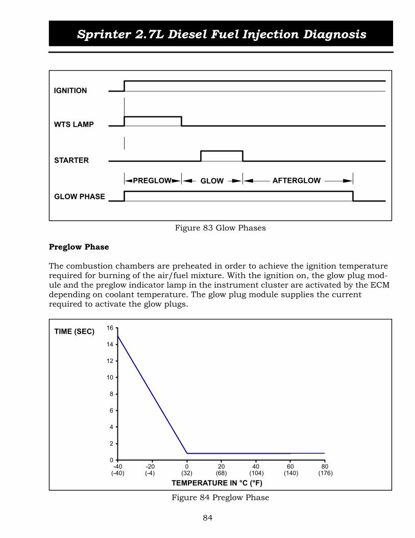
Sprinter 2.7L Diesel Fuel Injection Diagnosis
84
Figure 83 Glow Phases
Preglow Phase
The combustion chambers are preheated in order to achieve the ignition temperature required for burning of the air/fuel mixture. With the ignition on, the glow plug mod-ule and the preglow indicator lamp in the instrument cluster are activated by the ECM depending on coolant temperature. The glow plug module supplies the current required to activate the glow plugs.
Figure 84 Preglow Phase
IGNITION
WTS LAMP
STARTER
GLOW PHASE
GLOWPREGLOW AFTERGLOW
0
2
4
6
8
10
12
14
16
-40 -20 0 20 40 60 80(-40) (-4) (32) (68) (104) (140) (176)
TEMPERATURE IN °C (°F)
TIME (SEC)
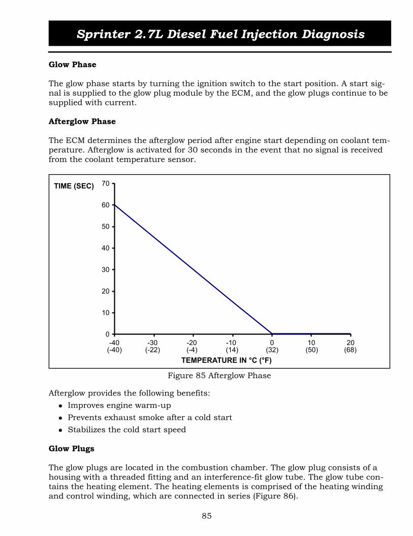
Sprinter 2.7L Diesel Fuel Injection Diagnosis
85
Glow Phase
The glow phase starts by turning the ignition switch to the start position. A start sig-nal is supplied to the glow plug module by the ECM, and the glow plugs continue to be supplied with current.
Afterglow Phase
The ECM determines the afterglow period after engine start depending on coolant tem-perature. Afterglow is activated for 30 seconds in the event that no signal is received from the coolant temperature sensor.
Figure 85 Afterglow Phase
Afterglow provides the following benefits: Improves engine warm-up Prevents exhaust smoke after a cold start Stabilizes the cold start speed
Glow Plugs
The glow plugs are located in the combustion chamber. The glow plug consists of a housing with a threaded fitting and an interference-fit glow tube. The glow tube con-tains the heating element. The heating elements is comprised of the heating winding and control winding, which are connected in series (Figure 86).
0
10
20
30
40
50
60
70
-40 -30 -20 -10 0 10 20(-40) (-22) (-4) (14) (32) (50) (68)
TEMPERATURE IN °C (°F)
TIME (SEC)

Sprinter 2.7L Diesel Fuel Injection Diagnosis
86
Figure 86 Glow Plug Heating Element
Operation
When the preglow system is activated, a current of approximately 30 A flows through each glow plug. The heating winding (1) heats up the glow plug. The control winding (2) increases its resistance as the temperature rises, and limits the current to about 15 to 25 A. The glow plugs are protected this way from overloads.
The glow plugs reach the temperature needed for ignition of 850°C (1562°F) in 4 sec-onds. The glow plug temperature is also limited to a non-critical level to allow activa-tion for up to 3 minutes following engine start.
Figure 87 Glow Plug Temperature vs. Time
1 Heating Winding 2 Control Winding
1
2
650 (1,202)
750 (1,382)
850 (1,562)
950 (1,742)
1,050 (1,922)
0 10 20 30 40 50
TIME (SEC)
TEMP IN °C (°F)

Sprinter 2.7L Diesel Fuel Injection Diagnosis
87
FUEL OUTPUTS
INJECTORS
The ECM controls the injection process separately for each cylinder and each crank-shaft revolution. The injectors incorporate fast-switching solenoid valves required for high-speed activation.
Figure 88 Injector Circuit Schematic
The fuel injectors are arranged in two groups (Figure 88). Injectors 1, 3 and 4 connect to a common high side terminal and injectors 2 and 5 share the other high side termi-nal. The ECM activates the injectors by controlling the ground side of each injector solenoid via metal-oxide-semiconductor field effect transistors (MOSFETS). The high side circuit produces the peak voltage required to activate the solenoids quickly.
CYL 3
CYL 4
CYL 2
CYL 5
ENGINECONTROL
MODULE(ECM)
CYL 1LOW SIDE
(GROUND CONTROL)
LOW SIDE(GROUND CONTROL)
LOW SIDE(GROUND CONTROL)
LOW SIDE(GROUND CONTROL)
LOW SIDE (GND.CTL)
HIGH SIDE
HIGH SIDE
B+
FILMCAPACITOR15uF/100 V

Sprinter 2.7L Diesel Fuel Injection Diagnosis
88
High Voltage Drive Circuit
In order to inject small pilot quantities of approximately 0.0015 cm³/stroke under high pressure conditions, the injector solenoid valves must switch quickly and reliably within 200 microseconds . To achieve this, the injector coil must be triggered with steep current flanks. This requires high voltages being made available in the ECM.
The ECM contains a special 4-pin metallized polyester film capacitor to ensure the fast switching of the fuel injector solenoid valves. The capacitor has a rated capacitance of 15 µF and a nominal voltage of 100V. At operating temperatures of up to 105 °C (221 °F), the capacitor supplies the necessary current to energize the solenoids. Current peaks of up to 30 A at high frequencies (kilohertz range) are produced during the unloading and charging phases of the capacitor.
Figure 89 ECM Printed Circuit Board Layout
By delivering the energy from the capacitor to the injector coil, the control current required to open the injector is reached within a few microseconds. Afterwards the voltage drops approximately to the electrical system level and the current flow is main-tained by the vehicle’s battery.
1 Injector Ground Control Driver Stage 2 Film Capacitor
12

Sprinter 2.7L Diesel Fuel Injection Diagnosis
89
The high voltage induced in the solenoid (Figure 90) is used to charge the capacitor. The capacitor is recharged with approximately 80 volts during the periods in which the solenoid is switched off (for most of the duration of the working, exhaust and compres-sion strokes).
Figure 90 Voltage Waveform, Injector Activation
Capacitor Unload/Charge Phases
See Figures 91 and 92 for the current waveform and solenoid activation phases. The low side (ground control) MOSFET is switched off and the injector solenoid is in the de-energized state (a).
In the pilot injection stage (1), the ECM switches on the low side MOSFET, which com-pletes the solenoid path to ground (b). The capacitor unloads producing a steep rise in current (b).
1 Injector Coil is Energized For Pilot Injection2 Injector Coil is De-Energized (Inductive Kick is Produced, Charging Capacitor)3 Injector Coil is Energized For Main Injection4 Injector Coil is De-Energized (Inductive Kick is Produced, Charging Capacitor)
1
2
3
4

Sprinter 2.7L Diesel Fuel Injection Diagnosis
90
The injector break-away starting phase (c) follows as current from the vehicle’s electri-cal system (B+) flows into the solenoid. During this phase, a two-step action circuit holds the current to a value (approximately 20 A), which guarantees a safe opening of the injector.
As the pilot injection ends, the capacitor charge phase begins (d). The low side MOS-FET is switched off, interrupting the flow of current to the injector solenoid. A high-voltage inductive kick is produced in the solenoid with reverse polarity. Current flows back through the diode and charges the capacitor.
After the brief solenoid de-energized state (a), the low side MOSFET is switched on for the main injection phase. The capacitor unloads its current (b), followed by the injec-tor break-away starting current (c).
Once the injector is stably open, the current level is lowered (d) for the duration of the injector holding current phase (approximately 12 A). During this phase, the current continues to switch alternately between two levels, which is sufficient to hold the sole-noid open (this is possible due to the magnetic air gap now being smaller) but not waste electric power. The current level is reduced to lower system energy requirements and to speed the flux decay when the ECM is turned off.
Figure 91 Current Waveform, Injector Activation
1 Pilot Injection c Injector Break-Away Starting Current2 Main Injection d Capacitor Charge Phasea Injector De-Energized State e Injector Holding Currentb Capacitor Unload Current
ba c d a b c d e d a
12
20
Current (A)
Time (ms)
1 2

Sprinter 2.7L Diesel Fuel Injection Diagnosis
91
Figure 92 Injector Solenoid Activation Phases
B+
ON
B+
ON
B+
OFF
HOLDINGCURRENT
ON
b. Capacitor Unload Current c. Injector Break-Away Starting Current
d. Capacitor Charge Phase e. Injector Solenoid Holding Current

Sprinter 2.7L Diesel Fuel Injection Diagnosis
92
Pilot Injection
With pilot injection, a small amount of diesel fuel is injected into the cylinder to reduce combustion noise and exhaust emission levels. Pilot injection is used throughout the entire operating range, up to an engine speed of approximately 3500 rpm. The ECM controls pilot injection by adjusting the following:
Start of pilot injection—based on the engine operating point, last start of actua-tion of main injection and coolant temperature Duration of pilot injection—based on the engine operating point, rail pressure, coolant temperature, atmospheric pressure and intake air temperature
Main Injection
The engine's torque and power are produced from the main injection phase. To control the main injected quantity, the ECM adjusts the following:
Start of main injection—based on the engine operating point, atmospheric pres-sure, coolant temperature, intake air temperature and pilot injection actuation Duration of main injection—based on rail pressure, the main injection duration is the difference of the total specified quantity and pilot injected quantity
Failure Modes
The ECM monitors the operation of the injectors and stores fault codes related to the following conditions:
Excess current on injector control or return wires Open or short circuits

Sprinter 2.7L Diesel Fuel Injection Diagnosis
93
FUEL PRESSURE SOLENOID
The fuel rail pressure solenoid is attached to the rear of the common rail (Figure 93).
Figure 93 Fuel Pressure Solenoid
Two wires connect the fuel pressure solenoid to the Engine Control Module (ECM). The ECM grounds one end of the solenoid and sends a PWM signal through the other end. The ECM controls and maintains the rail pressure by means of the PWM signal.
Figure 94 Fuel Rail Pressure Solenoid Schematic
The fuel pressure solenoid has the task of regulating the fuel pressure in the common rail to levels of up to 1350 bar (approximately 20,000 PSI). The desired value calcu-lated by the engine control unit determines the target pressure to be achieved. The fuel pressure sensor measures the actual pressure in the rail. Therefore, the fuel pressure solenoid, common rail, fuel pressure sensor and ECM together form a control loop.
E NG INEC ONT R OLMODUL E(E C M)
F UE L P R E S S UR ES OL E NOID
P WMS IG NA L
S IG NA LR E T UR N

Sprinter 2.7L Diesel Fuel Injection Diagnosis
94
Figure 95 Fuel Pressure Solenoid
Operation
When deactivated, the fuel pressure solenoid is closed, due to the spring force pressing the ball into the seat (Figure 95). The spring pressure maintains a minimum pressure of about 60 bar (870 PSI). When operating, the ECM regulates the PWM signal (Figure 96) and the fuel pressure solenoid opens to a greater or lesser degree. At idle the con-trol value is approximately 18%. The pressure of the fluid counteracts the force of the magnet coil and the spring force. A minimum fuel pressure of 200 bar (2900 PSI) must be achieved in order to start the engine.
Figure 96 Fuel Pressure Solenoid PWM Signal
1 Magnetic Coil 3 Ball And Seat2 Spring 4 High Pressure Fuel Supply
1
2
3
4

Sprinter 2.7L Diesel Fuel Injection Diagnosis
95
Failure Modes
The ECM monitors the operation of the fuel pressure solenoid and stores fault codes related to the following conditions:
Wire shorted to positive or shorted to ground Open circuit Plausibility
HIGH PRESSURE PUMP FUEL SHUTOFF VALVE
The high pressure fuel injection pump has a integrated shut off valve for one of the high pressure pump elements. The ECM monitors the fuel temperature and will switch off the element if the fuel temperature reaches above 136°C (278°F) with the engine speed above 2200 rpm. The shutoff valve is not serviced separately.
Figure 97 Fuel Shutoff Valve
Failure Modes
The ECM monitors the operation of the fuel shutoff valve and stores fault codes related to the following conditions:
Wire shorted to positive or shorted to ground Open circuit

Sprinter 2.7L Diesel Fuel Injection Diagnosis
96
ACTIVITY 4.1 SHOP DEMONSTRATION OF FUEL RELATED OUTPUTS
The purpose of this activity is to familiarize the students with the glow system compo-nents and related function tests.
1. Locate the C2 connector at the glow plug control module, check resistance through each glow plug to ground. Resistance Wire Size/ColorGlow Plug #1: _______________________________________________ Glow Plug #2: _______________________________________________ Glow Plug #3: _______________________________________________ Glow Plug #4: _______________________________________________ Glow Plug #5: _______________________________________________
2. What would incorrect resistance values indicate?
3. Are their any special tools associated with the Sprinter glow plugs?
4. Disconnect #1 glow plug. Check for DTCs and list below.
5. List any other DTCs related to the glow plug system.
6. How does the glow plug control module communicate with the ECM + DRBIII? List wire color, connector, and PIN.

Sprinter 2.7L Diesel Fuel Injection Diagnosis
97
INTAKE/EXHAUST OUTPUTS
BOOST PRESSURE SOLENOID
The boost pressure solenoid is located under the air filter housing and is responsible for turbo-charger boost pressure control. It controls vacuum in response to a PWM signal from the ECM. The vacuum signal is regulated by mixing the system vacuum (from the vacuum pump) with atmospheric pressure. The resulting vacuum is sent to the actuator unit at the turbocharger.
Figure 98 Boost Pressure Solenoid
OPERATION
When deactivated, the boost pressure solenoid is open to atmospheric pressure. The OUT port, which leads to the turbocharger vacuum valve is fully vented through the ATM port (Figure 99). The turbocharger vanes are in the open position (low boost). When operating, the PWM control signal from the ECM modulates the opening of the VAC port and the closing of the ATM port, which allows vacuum to be mixed with atmospheric pressure. The resulting vacuum goes out through the OUT connection to the turbocharger vacuum unit.
When the engine is at idle, the PWM control value is approximately 85%. The PWM control value decreases as the accelerator pedal is depressed.

Sprinter 2.7L Diesel Fuel Injection Diagnosis
98
Figure 99 Boost Pressure Solenoid Operating States
Failure Modes
The ECM monitors the operation of the boost pressure solenoid and stores fault codes related to the following conditions:
Wire shorted to positive or wire shorted to ground/open circuit Boost pressure is too low or too high Activation On/Off ratio is too high
EGR VALVE
The EGR valve housing is mounted between the charge air cooler hose and the intake manifold (Figure 100).
Figure 100 EGR Valve
1 Solenoid Deactivated State 2 Solenoid Activated State
OUT VAC
ATM
OUT VAC
ATM
1 2

Sprinter 2.7L Diesel Fuel Injection Diagnosis
99
Exhaust-gas recirculation (EGR) is a method for reducing the emissions of NOx. With EGR, a portion of the exhaust gases are diverted into the intake during part-load oper-ation. Not only is the oxygen content reduced, but also the rate of combustion and the peak temperature at the flame front, which results in lower NOx emissions.If too much exhaust gas is recirculated (exceeding 40% of the intake air volume), the particulates, CO, and HC emissions, as well as the fuel consumption rise due to the lack of oxygen.
Figure 101 EGR Valve Location
OPERATION
The mass of the air supplied to the cylinders per stroke is the decisive factor for deter-mining the optimum quantity of exhaust gas for the operating condition. The optimum quantity is calculated from the Mass Air Flow sensor information. The ECM evaluates this signal as well as that from the Boost Pressure sensor, and outputs a PWM signal in accordance with one of the maps stored in it. The signal is sent to the exhaust gas recirculation valve. The map is formulated to keep the NOx as low as possible. The EGR valve is actuated by an electric positioning motor (Figure 102).

Sprinter 2.7L Diesel Fuel Injection Diagnosis
100
Figure 102 EGR Valve Rear View
Failure Modes
The ECM monitors the operation of the EGR valve and stores fault codes related to the following conditions:
Open circuit Wire shorted to positive or shorted to ground Exhaust gas recirculation rate too high Exhaust gas recirculation rate too low Exhaust gas recirculation flow check
MIL LAMP
The engine malfunction indicator lamp is activated prior to the engine being started, with ignition ON (bulb check) and goes out after engine starts provided no fault exists. An emission-related fault may cause the lamp to stay illuminated. Not all failures ensure the illumination or the MIL lamp however.
1 Valve and Valve Seat 4 EGR Motor2 EGR Inlet Passage (From Exhaust) 5 Cam & Roller Mechanism3 EGR Outlet Passage (To Engine)
1
25
4
3

Sprinter 2.7L Diesel Fuel Injection Diagnosis
101
Figure 103 MIL Lamp
DATA LINK CONNECTOR
The Data Link Connector (DLC) is located under the instrument panel, on the left side of the driver’s leg room area. When connected to the DLC, the DRB III scan tool is able to establish communication with various control modules through individual diagnos-tic lines (K-Lines). A K-Line is a single wire that allows bi-directional data to be trans-mitted between control modules and a scan tool.
Figure 104 DLC Connector

Sprinter 2.7L Diesel Fuel Injection Diagnosis
102
The K-Line wiring is not connected to the CAN data bus. The K-Line is used for diag-nostic and monitoring functions, while the CAN data bus is a communications link used exclusively for control module data exchange.
CAN BUS OUTPUTS
The ECM transmits information via the CAN bus to various control modules.
Figure 105 CAN Bus Outputs
ECM
Con
trol
Mod
ule
CAB
Engine TorqueEngine SpeedDriver Input Torque (Pedal Position)
TCM
Engine TorqueEngine SpeedLimp-Home ModeCruise Control ActiveABS Input TorqueCoolant TemperatureEngine Temperature
SKR
EEM Request by ECM
Engine is Enabled
IC
MIL LampStart ErrorPreglow Indicator LampEngine Control Module FaultyOil TemperatureOil LevelOil QualityEngine SpeedCoolant Temperature
ATC A/C Compressor OFF (Full Load)
Engine SpeedCoolant Temperature
INFORMATION OUTPUT - CAN BUS

Sprinter 2.7L Diesel Fuel Injection Diagnosis
103
ACTIVITY 4.2 ACTIVATIONS OF INTAKE/EXHAUST DEVICES
The purpose of this activity is to familiarize the student with injector open circuit faults and performing the EGR valve actuation test with the DRB III scan tool.
TASK 1
1. Simulate an open circuit by disconnecting an injector with the ignition OFF. Attempt to start the engine after disconnecting the injector and record your find-ings in the chart below.
2. Reconnect the injector.
TASK 2
1. Start engine and view MAF sensor reading at idle. Record your reading below.
2. What is the MAF spec? Record your reading below.
3. Unplug MAF. What is the status of the engine light?
4. Are there any associated codes?
5. Reconnect the MAF. With the engine running. Perform EGR actuator test and record results below. ____________ % ____________ mg/strk (OPEN) ____________ % ____________ mg/strk (CLOSED)
6. Of the above readings, which of the two is introducing the most exhaust gas?
7. Shut off engine
INSTRUCTOR LEAD
8. What code(s) are set when the EGR valve is held close?
MIL lamp ON (YES/NO)
Limp-In Mode (YES/NO)
Engine Does Start (YES/NO)
Engine Stalls (YES/NO)
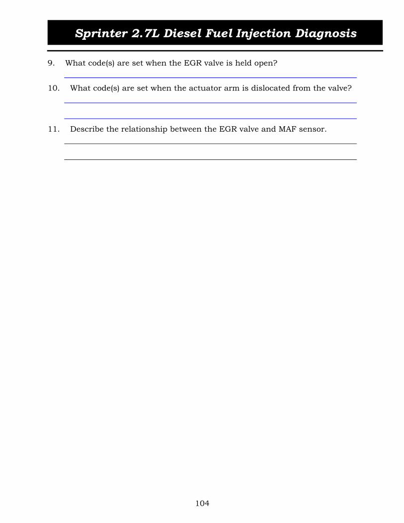
Sprinter 2.7L Diesel Fuel Injection Diagnosis
104
9. What code(s) are set when the EGR valve is held open?
10. What code(s) are set when the actuator arm is dislocated from the valve?
11. Describe the relationship between the EGR valve and MAF sensor.

Sprinter 2.7L Diesel Fuel Injection Diagnosis
105
MODULE 5 ENGINE DIAGNOSIS
Figure 106 Flow Chart, Six-Step Diagnostic Process
Start
1. Verify the complaint
2. Determine relatedsymptoms
3. Analyze symptoms
4. Isolate the problem
5. Repair isolated problem
6. Verify for proper operation
End

Sprinter 2.7L Diesel Fuel Injection Diagnosis
106
SIX-STEP DIAGNOSTIC PROCESS
Step 1: Verify the Customer Concern
Verifying the customer concern is the first step in the Six-Step Diagnostic Process. This step actually begins with the Service Writer/Advisor. The Service Writer/Advisor must get as much information as possible from the customer. It is important to know if the condition is constant or varies with road speed, is weather or temperature dependent (happens when cold or when raining, etc.), or only occurs when certain equipment is being used such as the air conditioning or radio with power booster.As a technician, the first thing you must do is accurately interpret the information. This may require talking to the customer and Service Writer/Advisor. Always dupli-cate the concern before attempting to correct it. Understanding and duplicating the symptom is important. It may be necessary to have the customer's help in duplicating the concern.
Step 2: Determine Related Symptoms
The next step in the Six-Step Diagnostic Process is troubleshooting the problem to determine if there are any related symptoms. The goal of this step is to gather infor-mation and associate the concern with a specific component.Once the primary symptom is identified, check to see if there are other customer con-cerns which may be related. Check the vehicle's service history to determine if any other repairs were performed for similar symptoms. Review any Technical Service Bul-letins (TSBs) to determine if any relate to the symptoms described by the customer. Perform a thorough visual inspection, including checking for non-factory installed accessories that may be causing the concern. Road testing a vehicle also may be nec-essary.
Step 3: Analyze the Symptoms
The next step in the Six-Step Diagnostic Process is to analyze the symptoms. The goal of this step is to justify the customer's claim and to classify the symptoms.Confirming that the vehicle has a problem is important. Attempting to repair a normal condition can convince the customer that a true problem exists when it doesn't. Knowing correct system operation helps to satisfy the customer when the condition is normal.
Step 4: Isolate the Concern
The next step in the Six-Step Diagnostic Process is to isolate the concern. The goal of this step is to use the results of the road and in-shop tests to help identify the actual cause and location of the customer concern.Isolating components from each other to determine which component is the cause of a vehicle concern is the basis of most diagnostic tests. Isolation may be as simple as lis-

Sprinter 2.7L Diesel Fuel Injection Diagnosis
107
tening to a suspect component with a mechanic's stethoscope, or running the vehicle with the suspect component removed.Use the Diagnosis Charts in the Service Manual to develop an action plan to determine which checks to make. Document any additional problems with the customer's vehi-cle. Pay particular attention to other concerns and problems that can cause an unsafe condition.
Step 5: Repair the Concern
The fifth step in the Six-Step Diagnostic Process is to make the necessary adjustments and repairs to correct the problem. The Service Manual may help when performing these operations.Always look for the cause of component damage. If you replace the component that is causing the symptom but do not try to determine what caused that component to fail, the failure is likely to recur.
Step 6: Verify Proper Operation
The last step in the Six-Step Diagnostic Process is to verify that the vehicle operates properly. Eliminating or isolating the problem is the optimal goal. If the customer must tolerate the concern, thoroughly explain to the customer why the condition exists. It is possible that fixing one concern may reveal another. Take the time to road test and verify that no further problems exist. Studies show that almost one out of three service visits requires a return visit to fully correct the problem.
TYPES OF EXHAUST SMOKE
The High-Pressure Common Rail (HPCR) diesel engine should emit very little smoke. White smoke is not considered normal. The different types of exhaust smoke indicate different problems. Following is a brief discussion of black, blue, and white exhaust smoke.
Black Smoke
Black smoke is created by incomplete combustion. The reason for the fuel being only partially burned often relates to one of the following problems:
Excess fuel in the combustion chamber Insufficient air supply (clogged air filter, kinked hoses, faulty turbo) Advanced injection timing due to poor diesel fuel quality not recommended being used in the vehicle
Black smoke is caused by too much fuel or poor fuel quality and not enough air or time to burn the fuel. Black smoke is not considered normal and is often related to low power or poor fuel economy problems.

Sprinter 2.7L Diesel Fuel Injection Diagnosis
108
Blue Smoke
Blue smoke is an indication of engine oil burning in the combustion chamber. Blue smoke is usually accompanied by excessive oil consumption. Any of the following con-ditions can cause excessive oil consumption:
Overfilled crankcase Worn piston rings Failed valve stem seals Failed turbocharger seals
White Smoke
White smoke is caused by particles of fuel passing through the combustion chamber without burning and exiting with the exhaust gas. Fuel not burning is often related to low combustion chamber temperature. At light loads, the temperature in the combus-tion chamber may drop to 260°C (500°F). The lower temperature delays combustion, causing some fuel to be partially burned and blown out with the exhaust gas.
NO DTC DIAGNOSIS
When diagnosing diesel driveability concerns in the absence of codes, use the symp-tom-based diagnostic tables in the Service Information. Always follow the Six-Step Diagnostic Process when diagnosing a customer concern.
HIGH-PRESSURE DIAGNOSIS
The high-pressure fuel system can be diagnosed using a DRBIII. The DRBIII will show the fuel pressure setpoint and the actual pressure. If the actual pressure and the fuel pressure setpoint values are about the same, a concern with the high-pressure fuel system may not be present. If a small leak is suspected in the high-pressure lines, check them by using the cardboard test.
WARNING: THE HIGH-PRESSURE FUEL PUMP SUPPLIES FUEL WITH PRESSURES AS HIGH AS 1350 BAR (20,000 PSI) TO EACH INJECTOR THROUGH THE HIGH-PRESSURE LINES. FUEL UNDER THIS AMOUNT OF PRESSURE CAN PENETRATE THE SKIN AND CAUSE PERSONAL INJURY. WEAR SAFETY GOGGLES AND ADE-QUATE PROTECTIVE CLOTHING AND AVOID CONTACT WITH FUEL SPRAY WHEN CHECKING HIGH-PRESSURE LINES FOR LEAKS
DIAGNOSIS WITH RELATED FAULT CODES
The ECM stores diagnostic information in the EEPROM. When fault codes are present, follow the proper diagnostic steps in the service information.
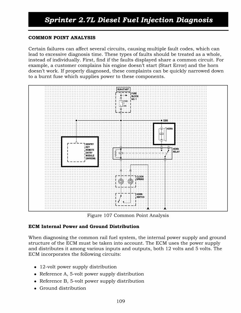
Sprinter 2.7L Diesel Fuel Injection Diagnosis
109
COMMON POINT ANALYSIS
Certain failures can affect several circuits, causing multiple fault codes, which can lead to excessive diagnosis time. These types of faults should be treated as a whole, instead of individually. First, find if the faults displayed share a common circuit. For example, a customer complains his engine doesn’t start (Start Error) and the horn doesn’t work. If properly diagnosed, these complaints can be quickly narrowed down to a burnt fuse which supplies power to these components.
Figure 107 Common Point Analysis
ECM Internal Power and Ground Distribution
When diagnosing the common rail fuel system, the internal power supply and ground structure of the ECM must be taken into account. The ECM uses the power supply and distributes it among various inputs and outputs, both 12 volts and 5 volts. The ECM incorporates the following circuits:
12-volt power supply distribution Reference A, 5-volt power supply distribution Reference B, 5-volt power supply distribution Ground distribution

Sprinter 2.7L Diesel Fuel Injection Diagnosis
110
Internal Common Point Analysis, 12-Volt Power Supply Distribution
Figure 108 ECM, 12 Volt Supply
A Cruise Control Switch 12 V SupplyB Mass Air Flow (MAF) Sensor 12 V SupplyC Charge Pressure Transducer 12 V SupplyD Water in Fuel (WIF) Sensor 12 V SupplyE Pump Element Shutoff Valve 12 V Supply

Sprinter 2.7L Diesel Fuel Injection Diagnosis
111
Internal Common Point Analysis, 5 Volt Reference A
Figure 109 ECM, 5 Volt Supply (A)
F Not UsedG Accelerator Pedal Position Sensor (APP) 5 V SupplyH Mass Air Flow Sensor (MAF) 5 V SupplyI Not UsedJ Oil Sensor 5 V Supply

Sprinter 2.7L Diesel Fuel Injection Diagnosis
112
Internal Common Point Analysis, 5 Volt Reference B
Figure 110 ECM, 5 Volt Supply (B)
K Not UsedL Boost Pressure Sensor 5 V SupplyM Not UsedN Low Fuel Pressure Sensor 5 V SupplyO Rail Pressure Sensor 5 V Supply

Sprinter 2.7L Diesel Fuel Injection Diagnosis
113
Internal Common Point Analysis, Grounds
Figure 111 ECM, Ground
P Kick Down Switch GroundQ Rail Pressure Sensor GroundR Fuel Low Pressure Sensor GroundS Camshaft Position Sensor GroundT Exhaust Gas Recirculation Valve and Engine Oil Sensor GroundU Fuel Temperature Sensor GroundV Coolant Temperature Sensor Ground
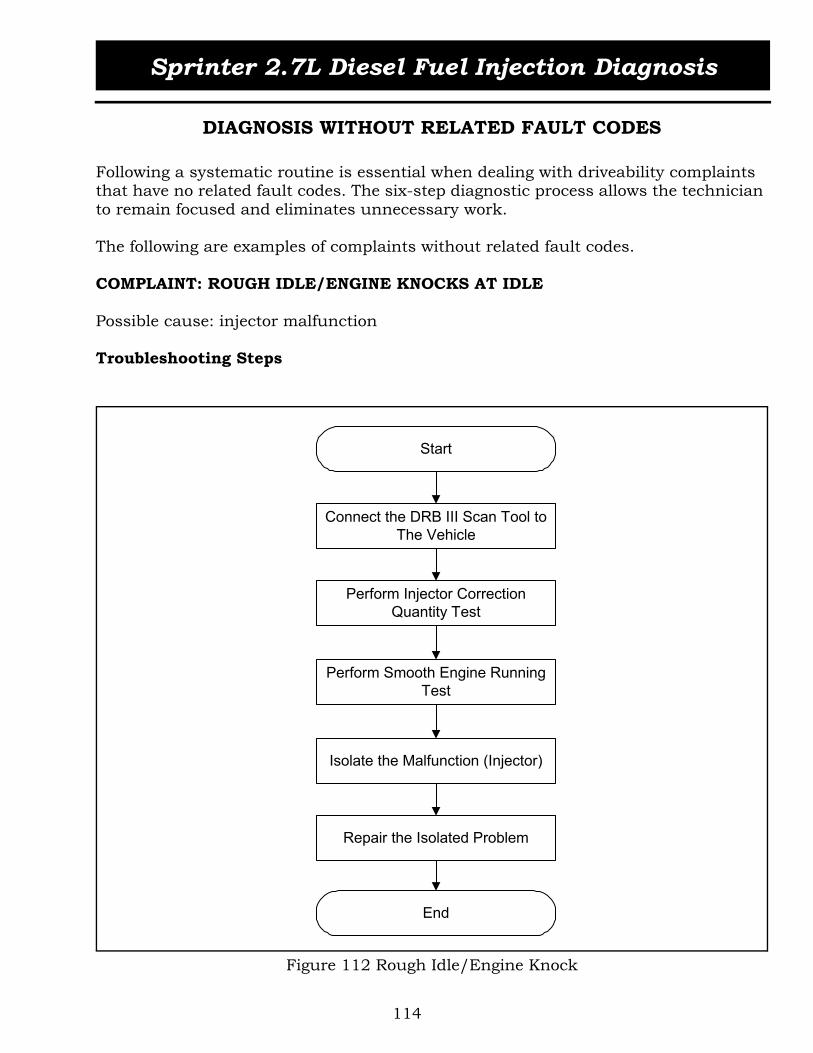
Sprinter 2.7L Diesel Fuel Injection Diagnosis
114
DIAGNOSIS WITHOUT RELATED FAULT CODES
Following a systematic routine is essential when dealing with driveability complaints that have no related fault codes. The six-step diagnostic process allows the technician to remain focused and eliminates unnecessary work.
The following are examples of complaints without related fault codes.
COMPLAINT: ROUGH IDLE/ENGINE KNOCKS AT IDLE
Possible cause: injector malfunction
Troubleshooting Steps
Figure 112 Rough Idle/Engine Knock
Start
Perform Injector CorrectionQuantity Test
Perform Smooth Engine RunningTest
End
Isolate the Malfunction (Injector)
Repair the Isolated Problem
Connect the DRB III Scan Tool toThe Vehicle

Sprinter 2.7L Diesel Fuel Injection Diagnosis
115
COMPLAINT: ENGINE CRANKS, BUT DOESN'T START
Possible causes: Insufficient fuel pressure – low or high pressure circuits Insufficient Low pressure pump output Fuel pressure sensor malfunction Fuel pressure solenoid malfunction Leaking injector High pressure pump failure CPS pulse ring or flex plate damage
Troubleshooting Steps
Figure 113 Engine Does Not Start
Start
Perform Fuel Pressure Sensor Check
Voltage to Pressure Comparison
End
Verify Condition of Flex Plate with DRB III Scope
Repair the Isolated Problem
Check Fuel Pressure Values with DRB. Confirm if Necessary
Perform Fuel Pressure Solenoid Check
Check Pulse Width of Fuel Pressure Solenoid
Injector Leakage Check

Sprinter 2.7L Diesel Fuel Injection Diagnosis
116
COMPLAINT: POWER LOSS/ENGINE DIES UNDER LOAD
Possible causes: Injector malfunction Fuel pressure solenoid malfunction High pressure pump fluctuates under load
Troubleshooting Steps
Figure 114 Power Loss/Engine Dies
Start
Perform Injector CorrectionQuantity Test
Perform Fuel Pressure SolenoidCheck
End
Check High Pressure Pump forPressure Fluctuations
Repair the Isolated Problem
Connect the DRB III Scan Tool toThe Vehicle

Sprinter 2.7L Diesel Fuel Injection Diagnosis
117
COMPLAINT: BLACK SMOKE
(Smoke diagnosis review)Possible cause: rail pressure sensor malfunction
Troubleshooting Step
Figure 115 Black Smoke
Start
Connect the DRB III Scan Tool toThe Vehicle
Perform Rail Pressure SensorCheck
End
Repair the Isolated Problem
Smoke Diagnosis Review

Sprinter 2.7L Diesel Fuel Injection Diagnosis
118
COMPLAINT: ENGINE RPM DROPS INTERMITTENTLY
Possible cause: stop lamp switch misadjusted/malfunction
Troubleshooting step
Figure 116 Engine RPM Drop
Start
Check Operation of Brake SwitchDual Contacts
Check Brake Switch Adjustment
End
Repair the Isolated Problem
Connect the DRB III Scan Tool toThe Vehicle

Sprinter 2.7L Diesel Fuel Injection Diagnosis
119
ACTIVITY 5.1 : TROUBLESHOOTING PROBLEMS ON VEHICLE
The purpose of this activity is to allow the students to perform driveability trouble-shooting procedures using the DRB III scan tool and the six-step diagnostic process.
TASK 1 (GROUP 1) LOW POWER AND ENGINE RUNNING ROUGH
1. Go to the shop vehicle assigned by your instructor. The hood is to remain closed during the analysis.
2. Connect the DRB III Scan Tool and perform an engine compression test.3. What are the required conditions for the engine compression test?
4. Record the engine compression readings in the spaces below:Cylinder 1: __________________________________________Cylinder 2: __________________________________________Cylinder 3: __________________________________________Cylinder 4: __________________________________________Cylinder 5: __________________________________________
5. Is the cylinder compression within specifications?
YES NO _______________________________________________________
6. Perform an injector correction quantity test.7. What are the required conditions for the injector correction quantity test?
8. Record the injector correction quantity readings in the spaces below:Cylinder 1: __________________________________________Cylinder 2: __________________________________________Cylinder 3: __________________________________________Cylinder 4: __________________________________________Cylinder 5: __________________________________________
9. Are the injector correction quantities within specifications?
YES NO ________________________________________________________
10. Perform a smooth running test.11. What are the required conditions for the smooth running test?

Sprinter 2.7L Diesel Fuel Injection Diagnosis
120
12. Record the smooth running test readings in the spaces below:Cylinder 1: ___________________________________________Cylinder 2: ___________________________________________Cylinder 3: ___________________________________________Cylinder 4: ___________________________________________Cylinder 5: ___________________________________________
13. Are the smooth running test values within specifications?
YES NO
14. What is the possible root cause of this driveability complaint?
TASK 1 (GROUP 2) ENGINE RUNNING ROUGH AND LOW POWER
1. Go to the shop vehicle assigned by your instructor. The hood is to remain closed during the analysis.
2. Connect the DRB III Scan Tool and perform an engine compression test.3. What are the required conditions for the engine compression test?
4. Record the engine compression readings in the spaces below:Cylinder 1: ___________________________________________Cylinder 2: ___________________________________________Cylinder 3: ___________________________________________Cylinder 4: ___________________________________________Cylinder 5: ___________________________________________
5. Is the cylinder compression within specifications?
YES NO
6. Perform an injector correction quantity test.7. What are the required conditions for the injector correction quantity test?
8. Record the injector correction quantity readings in the spaces below:Cylinder 1: ___________________________________________Cylinder 2: ___________________________________________Cylinder 3: ___________________________________________Cylinder 4: ___________________________________________Cylinder 5: ___________________________________________

Sprinter 2.7L Diesel Fuel Injection Diagnosis
121
9. Are the injector correction quantities within specifications?
YES NO
10. Perform a smooth running test.11. What are the required conditions for the smooth running test?
12. Record the smooth running test readings in the spaces below:Cylinder 1: ____________________________________________Cylinder 2: ____________________________________________Cylinder 3: ____________________________________________Cylinder 4: ____________________________________________Cylinder 5: ____________________________________________
13. Are the smooth running test values within specifications?
YES NO
14. What is the possible root cause of this driveability complaint?
TASK 2 (GROUP 1) ENGINE WON’T RUN
1. Go to the shop vehicle assigned by your instructor. The hood is to remain closed during the analysis.
2. Connect the DRB III Scan Tool and go into the Inputs/Outputs screen.3. Observe the I/O values. What are your findings?
4. What is the possible root cause of this driveability complaint?

Sprinter 2.7L Diesel Fuel Injection Diagnosis
122
TASK 2 (GROUP 2) ENGINE WON’T RUN
1. Go to the shop vehicle assigned by your instructor. The hood is to remain closed during the analysis.
2. Write down a detailed diagnostic step procedure for troubleshooting this condition
3. What is the possible root cause of this driveability complaint?
4. Inform your instructor of the results of your troubleshooting procedure

Sprinter 2.7L Diesel Fuel Injection Diagnosis
123
APPENDIX
OSCILLOSCOPE PATTERNS
CRANK AND CAM SIGNALS
Figure 117 shows the pattern of the crankshaft position sensor (CKP)at idle speed. Notice the voltage gap resulting from the two missing teeth on the flywheel.
Figure 117 Crankshaft Position Sensor Signal
Figure 118 shows the pattern of the camshaft position sensor at idle speed. The 5-volt signal switches to a low voltage level when the segment for identification of cylinder No.1 is detected.
Figure 118 Camshaft Position Sensor Signal
2ms/Divv20
10
0
-10
-20
50ms/Divv6
4
2
0

Sprinter 2.7L Diesel Fuel Injection Diagnosis
124
Figure 119 shows the relationship between the CKP and CMP sensor signals
Figure 119 Crank (CKP) and Cam (CMP) Signals
Figure 120 shows the normal pattern of the CMP (Channel 1) and CKP (Channel 2) sig-nals at idle.
Figure 120 Crank and Cam Signals

Sprinter 2.7L Diesel Fuel Injection Diagnosis
125
Figure 121 shows the normal pattern of the CKP sensor (wires 1 and 2).
Figure 121 Crank (CKP) Sensor Signal
Figure 122 shows the Crank (CKP) Sensor pattern. Channel 2 shows the sensor wire No. 1 is shorted to ground.
Figure 122 Shorted Crank Signal

Sprinter 2.7L Diesel Fuel Injection Diagnosis
126
MASS AIR FLOW (MAF) SENSOR SIGNAL
Figure 123 shows the pattern of the signal of the mass air flow sensor (MAF) at idle speed and under acceleration (observe the voltage rise).
Figure 123 Mass Air Flow (MAF) Sensor Signal
FUEL RAIL PRESSURE SENSOR SIGNAL
Figure 124 shows the pattern of the rail pressure sensor signal at different stages: ignition off, ignition on, idle speed and snapping the throttle.
Figure 124 Rail Pressure Sensor Signal
2s/Divv
3
2
1
0
4
1s/Divv
3
2
1
0
4
Ign.OFF
Ign.ON
Idle
Throttle Snap

Sprinter 2.7L Diesel Fuel Injection Diagnosis
127
FUEL INJECTOR PATTERN
Figure 125 shows the pattern of an injector at idle speed. The first voltage spike indi-cates the pilot injection phase. The second voltage spike indicates the main injection phase.
Figure 125 Fuel Injector Signal
FUEL PRESSURE SOLENOID
Figure 126 shows the pattern of the fuel pressure solenoid at idle speed.
Figure 126 Fuel Pressure Solenoid Signal at Idle
2ms/Divv
20
10
0
-10
-20
30
40
500us/Div
20
10
0
-10
30v

Sprinter 2.7L Diesel Fuel Injection Diagnosis
128
Figure 127 shows the pattern of the fuel pressure solenoid at full load.
Figure 127 Fuel Pressure Solenoid Signal at Full Load
Figure 128 shows the pattern of the fuel pressure solenoid during the ECM power-off phase.
Figure 128 Fuel Pressure Solenoid Signal, ECM Power-Off Phase
500us/Div
20
10
0
-10
30
v

Sprinter 2.7L Diesel Fuel Injection Diagnosis
129
EGR VALVE
Figure 129 shows the PWM signal to the EGR valve with the engine off/key on.
Figure 129 EGR Valve PWM Signal, Engine OFF/Key ON
Figure 130 shows the EGR valve signal with the engine at idle.
Figure 130 EGR Valve PWM Signal at Idle

Sprinter 2.7L Diesel Fuel Injection Diagnosis
130
Figure 131 shows the EGR valve signal with the engine under acceleration.
Figure 131 EGR Valve PWM Signal Under Acceleration
BOOST PRESSURE SOLENOID
Figure 132 shows the PWM signal to the Boost Pressure Solenoid with the engine off/key on.
Figure 132 Boost Pressure Solenoid PWM Signal, Engine OFF/Key ON
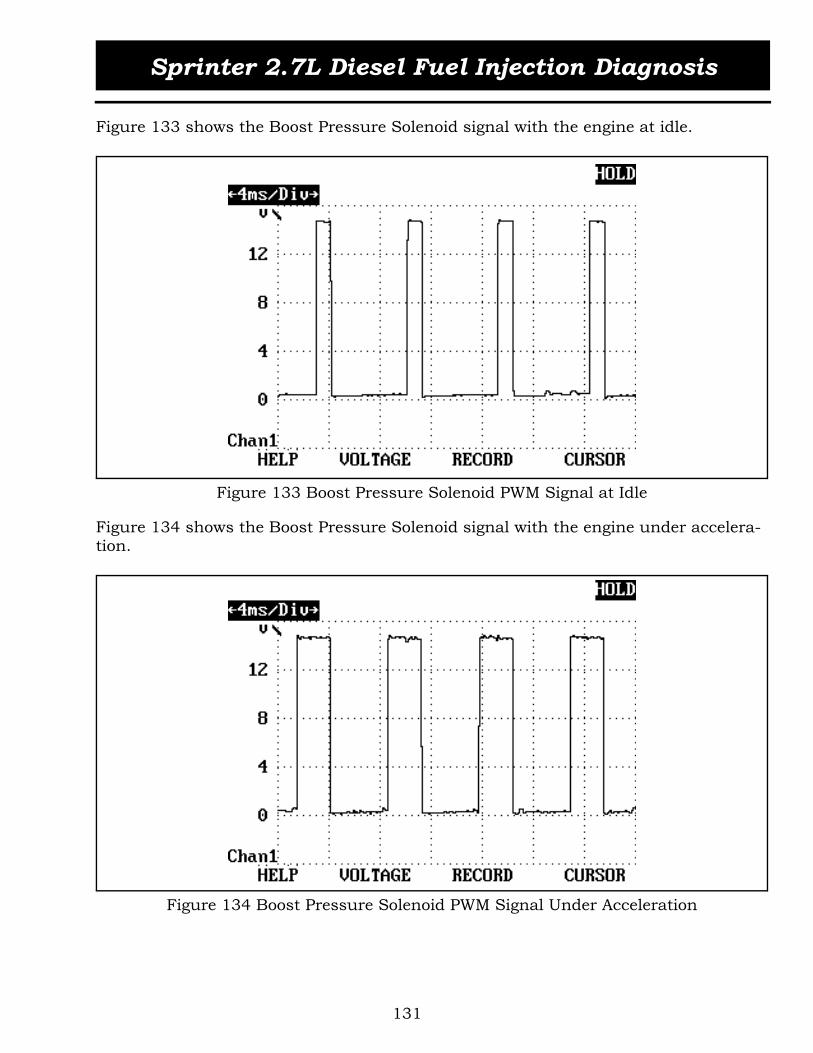
Sprinter 2.7L Diesel Fuel Injection Diagnosis
131
Figure 133 shows the Boost Pressure Solenoid signal with the engine at idle.
Figure 133 Boost Pressure Solenoid PWM Signal at Idle
Figure 134 shows the Boost Pressure Solenoid signal with the engine under accelera-tion.
Figure 134 Boost Pressure Solenoid PWM Signal Under Acceleration

Sprinter 2.7L Diesel Fuel Injection Diagnosis
132
ENGINE OIL SENSOR
Figure 135 shows the pattern of the oil sensor. The first waveform (1) represents the oil temperature. The duty-cycle lower limit is 20%, which indicates an oil temperature of -40°. The upper limit is 80%, which indicates an oil temperature above 160°C.
The second waveform (2) represents the oil level value. The duty-cycle lower limit is 20%, which indicates an oil level of 0. The upper limit is 80%, which indicates an oil level of 80mm.
The third waveform (3) represents the dielectric number of the oil. The duty-cycle lower limit is 20%, which indicates a dielectric number of 1. The upper limit is 80%, which indicates a dielectric number of 6. The typical value is around 40%, indicating an oil quality of 2.7.
Figure 135 Oil Sensor Signal
1 Oil Temperature Waveform2 Oil Level Waveform3 Dielectric Number of Oil Waveform (Oil Quality)
1 2 3

Sprinter 2.7L Diesel Fuel Injection Diagnosis
133
GLOW PLUG MODULE
Figure 136 shows the digital pattern (PWM) in the signal wire between the glow plug module and the engine control module (ECM).
Figure 136 Glow Plug Module Signal

Sprinter 2.7L Diesel Fuel Injection Diagnosis
134
SENSOR REFERENCE
Also with 4-13 shorted hi3-19 MAF shorted hi/loAPP 5v shorted hi/lo
NO MIL STARTS AND RUNS MIL NO CRANK
P1192 EOS open/ground get a sync error 1 (with engine running)
Injector shorted hi/lo – by shorting one it could read out any of the injectors
Common driver open or shorted P1661 compactor code - replace ecm – check injec-tors first
Hi fuel pressure sensor shorted hi or open – stayed running with a loping engine
Reference: A HighP0100 maf supply hi/loP1611 sensor ref A volts too hiP1192 EOS supply hi/lo – (shorted HI)P1222 APP1 supply hi/loP1234 APP2 supply hi/lo
Reference: B HighP0190 fuel pressure volts hiP0190 supply too hi/lo – (shorted HI)P0105 BPS supply too hi/loP2306 ref B too hi
Reference: A LowP0100 maf supply hi/loP1611 P1192 EOS supply hi/lo – (Shorted low)P1192 EOS open/short groundP1222 APP1 supply voltage hi/loP1234 APP2 supply voltage hi/lo
Reference: B LowP0190 fuel pressure volts hi (check)P0190 supply too hi/lo – (shorted low)P0105 BPS supply too hi/loP2306 ref B too lo
1 1 engine relay output – if openP0100 maf volt loP1403 egr sol openP1470 boost sol open or stg short to groundP1188 fuel shut down sol openDrop 12v outputs
1-7 engine relay output – if openP0615 starter relay openP1615 ecm voltage too loP1190 fuel pressure sol too loDrops 12v output to starter and fuel pressure sol
1-8 engine relay output – if openanyone of the injector over current hi sideif you crank with 1-8 open

Sprinter 2.7L Diesel Fuel Injection Diagnosis
135
Jumper 3-46 engine control relay control to ground
You can measure relay output at 1-1, 1-7, 1-8 will confirm the entire circuit
Cruise control switch open accel, decel, or resume set positive acceleration deviation

Sprinter 2.7L Diesel Fuel Injection Diagnosis
136
RETROFITTING SPEED CONTROL
This retrofit consists of installing a speed control switch in the steering columnand changing the version coding of the engine control module (ECM) to enable the speed control feature.
PARTS REQUIRED
Following is the list of parts. The electrical wires listed must be purchased locally. It is strongly recommended to adhere to the color coding of the wires. It simplifies service procedures, troubleshooting of the electrical system, and is consistent with shop docu-mentation and electrical wiring schematics.
Table 1 Parts List
PROCEDURE
1. Disconnect the cable from the negative battery post.2. Remove fuse panel cover (1) by turning slotted screw 90° from position A to B (Fig-
ure 137).
MB Part Number Description Qty.
A 001 540 14 45 Speed control switch 1
N007985 003129 Screw 1
A 655 545 02 28 Six-pin connector 1
A 011 545 81 26 Electrical terminal 6
A 008 545 63 26 Electrical terminal, ECM connector 6
- purchase locally - Red electrical wire, 18 AWG 1 ft.
- purchase locally - Black electrical wire, 18 AWG 1 ft.
- purchase locally - Blue electrical wire, 18 AWG 1 ft.
- purchase locally - Yellow electrical wire, 18 AWG 1 ft.
- purchase locally - Dark green electrical wire, 18 AWG 1 ft.
- purchase locally - Gray electrical wire, 18 AWG 1 ft.

Sprinter 2.7L Diesel Fuel Injection Diagnosis
137
Figure 137 Removal of Fuse Panel Cover
3. Unscrew Phillips screws and nut (Figure 138). Remove steering column cover. Remove M relay for better access to steering column bracket.
Figure 138 Removal of steering column cover and relay M

Sprinter 2.7L Diesel Fuel Injection Diagnosis
138
4. Unscrew both Phillips screws and remove upper cover (Figure 139).
Figure 139 Removal of Phillips Screws and Upper Cover
5. Remove steering column bracket bolts (Figure 140).
Figure 140 Removing Steering Column Bracket Bolts

Sprinter 2.7L Diesel Fuel Injection Diagnosis
139
6. Gently lower steering column about 6 inches (Figure 141).
Figure 141 Lowering The Steering Column
7. Locate the speed control switch mounting base (arrow) on the back of the combi-nation switch (Figure 142).
Figure 142 Location of speed control switch mounting base

Sprinter 2.7L Diesel Fuel Injection Diagnosis
140
8. Slide the speed control switch, part A 001 540 14 45 into its mounting base. Secure the switch with holding screw, part N007985 003129 (Figure 143).
Figure 143 Speed Control Switch Installation
9. Ensure all connectors on the back of Fuse Block No.1 are tight. Gently raise the steering column and reinstall the column bracket bolts (Figure 144). Tighten the bolts to 25 Nm (18 lb.ft).
Figure 144 Raising the Steering Column and Reinstalling Bracket Bolts
10. Route the speed control switch cable down the steering column towards the engine control module (ECM). See Figure 145.
1 Switch Mounting Screw 2 Switch Mounting Base

Sprinter 2.7L Diesel Fuel Injection Diagnosis
141
Figure 145 Routing of the speed control switch harness
11. Locate the engine control module (ECM) below the left knee protection next to the steering column (Figure 146). Pull the ECM down at the connection side until it releases. Pull it forward and out of the mounting bracket. Remove all five con-nectors from the ECM.
Figure 146 Location of the engine control module (ECM)

Sprinter 2.7L Diesel Fuel Injection Diagnosis
142
12. The ECM connectors (with male terminals) are numbered 1 through 5. Locate the harness end connector No. 2 (black 24-pin connector) and gently remove its cover to expose the wire insertion end of the connector.
Figure 147 Harness Connector No. 2
13. Assemble an extension harness with the color-coded wires described in the parts list (Figure 148). Cut one piece out of each wire color, 12 inches long, and strip both ends of wire. Install six terminals, part A 011 545 81 26, to one end of the wires, and six terminals, part A 008 545 63 26, to the other end.
Insert the terminals, part A 011 545 81 26, into the cavities of the six-pin connec-tor, part A 655 545 02 28 as follows: gray wire into cavity #1; black wire into cav-ity #2; blue wire into cavity #3; yellow wire into cavity #4; green wire into cavity #5, and red wire into cavity #6. Insert the wires until they click into place. Gently tug on the wires to make sure they are secure.
Now insert the other end of the wires with terminals, part A 008 545 63 26, into the cavities of the 24-pin connector of the engine control module (ECM) as follows: gray wire into cavity #22; black wire into cavity #21; blue wire into cavity #20; yel-low wire into cavity #16; green wire into cavity #14, and red wire into cavity #19. Insert the wires until they click into place. Gently tug on the wires to make sure they are secure.

Sprinter 2.7L Diesel Fuel Injection Diagnosis
143
Figure 148 Assembling the extension harness to the engine control module
14. Check the wires and cavities for proper position with the wiring diagram below (Figure 149). Plug the six-pin connector to the speed control switch connector. Install the cover onto the 24-pin connector. Install all five connectors back to the engine control module (ECM) and push the module back into its mounting bracket. Ensure the ECM is properly held in place by means of the tensioning spring clips.
Figure 149 Wiring diagram, speed control circuit
12 V OL T S UP P L YS P E E DC ONT R OLS WIT C H
E NG INEC ONT R OLMODUL E(E C M)
R E S UME S IG NA L
DE C E L /S E T S IG NA L
V E R IF IC A T ION S IG NA L
ON/OF F S IG NA L
A C C E L /S E T S IG NA L
R E D
B L UE
G R E E N
Y E L L OW
G R A Y
B L A C K
1
2
4
5
3
6 6
3
5
4
1
2
22
21
16
14
20
19
C 2
C 2
C 2
C 2
C 2
C 2

Sprinter 2.7L Diesel Fuel Injection Diagnosis
144
15. Reinstall the upper and lower steering column covers (Figure 150). The upper cover has a slot on the back (arrow) for the speed control switch lever. Reinstall the M relay and the fuse block locking cover.
Figure 150 Reinstalling the upper and lower steering column covers
16. Reconnect the battery and connect the DRB III scan tool to the vehicle. Choose Engine in the System Select screen, and Miscellaneous Functions in the Select Function screen (Figure 151).
Figure 151 Selecting Engine and Miscellaneous Functions
17. In the Miscellaneous Functions screen select Configuration (Figure 152).

Sprinter 2.7L Diesel Fuel Injection Diagnosis
145
Figure 152 Selecting Configuration
18. When asked, select Cruise Control Installed (Figure 152).
Figure 153 Key Off and Progress Bar Screens
19. Switch the ignition OFF and wait for the progress bar to indicate the completion of the configuration process (Figure 153).
20. Switch the ignition ON (Figure 154). The speed control installation is now com-plete.
Figure 154 Key ON Screen