springside pond restoration project - massachusetts springside... · springside pond restoration...
TRANSCRIPT
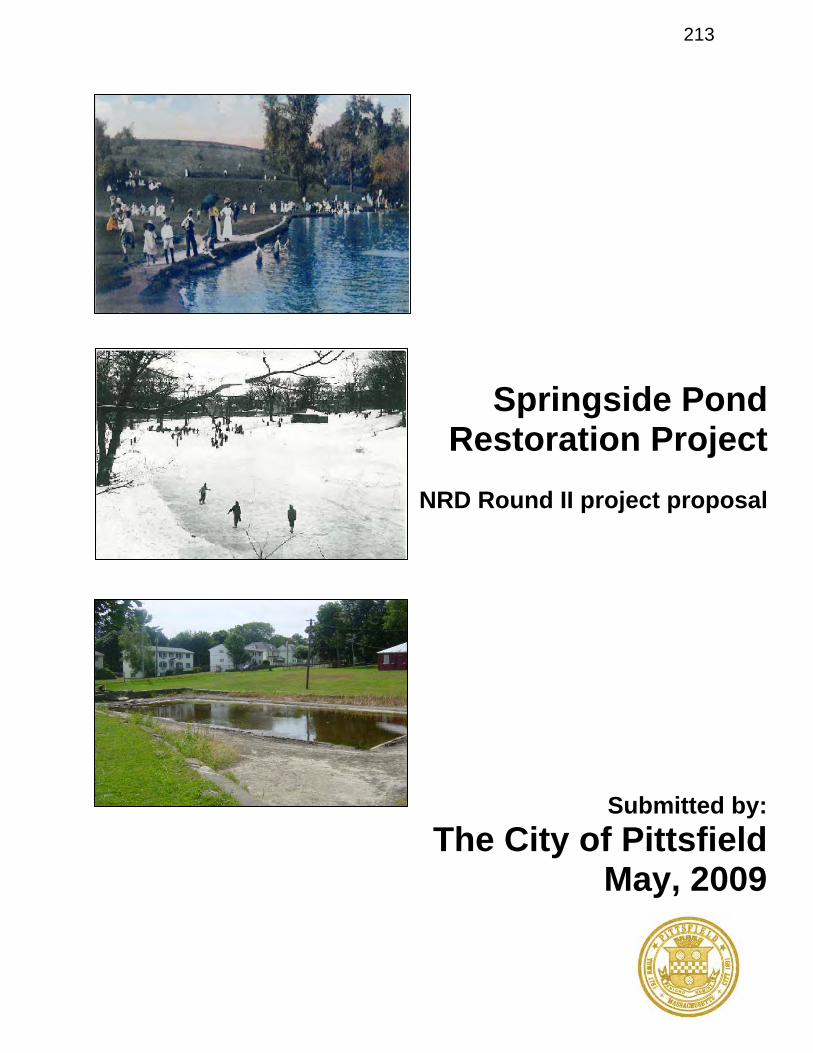
Springside Pond Restoration Project
NRD Round II project proposal
Submitted by:The City of Pittsfield
May, 2009
213
HOUSATONIC RIVERNATURAL RESOURCE DAMAGES FUND ROUND 2, 2008 Massachusetts Sub Council
Project Proposal Form
PART A. APPLICANT AND PROJECT INFORMATION
APPLICANT INFORMATION
Type of Entity Check the box that best describes the applicant.
[ ] Private individual [ ] Non-profit organization[ ] State government[ ] Federal government[ ] Tribal government
[ X ] Municipal government[ ] Corporation or Business[ ] County government[ ] Academic Institution[ ] Other (explain)
Authorized Representative of Applicant
Name
Title
Address
Address
City State Zip
Phone:
Email:
Contact Person (if different)
James M. Ruberto James R. McGrathName
Mayor Park, Open Space, & Natural Resource Prog. Man.
Title
AddressCity of Pittsfield City of Pittsfield
70 Allen Street 70 Allen Street
Address
City State Zip Pittsfield MA 01201 Pittsfield MA 01201
Phone:(413) 499-9344(413) 499-9321
Email:[email protected]@pittsfieldch.com
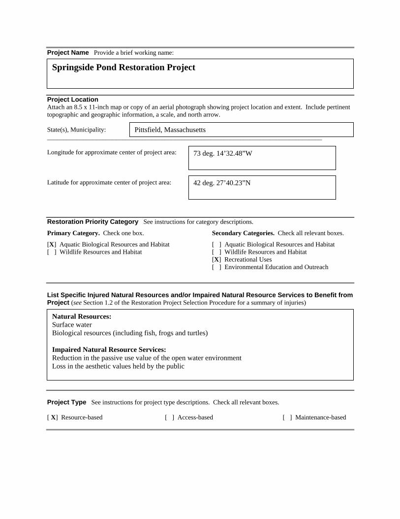
Project Name Provide a brief working name:
Springside Pond Restoration Project
Project LocationAttach an 8.5 x 11-inch map or copy of an aerial photograph showing project location and extent. Include pertinenttopographic and geographic information, a scale, and north arrow.
State(s), Municipality:____________________________________________________________________________________
Pittsfield, Massachusetts
Longitude for approximate center of project area: 73 deg. 14’32.48”W
Latitude for approximate center of project area: 42 deg. 27’40.23”N
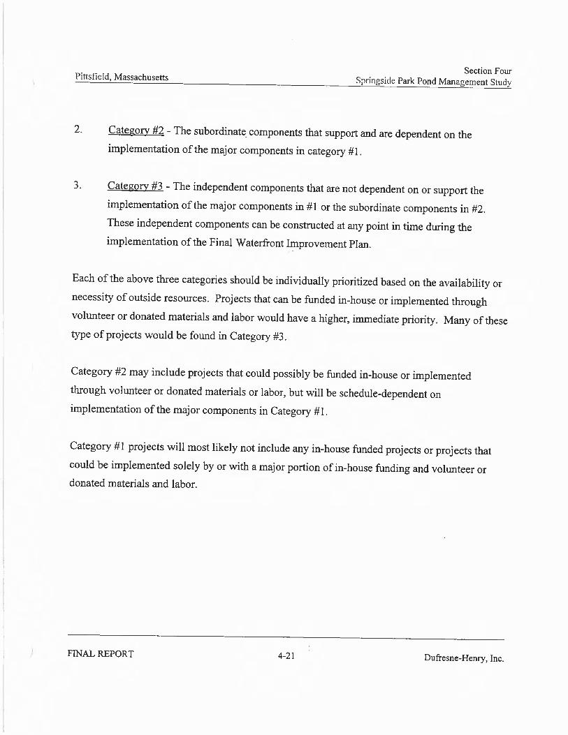
Restoration Priority Category See instructions for category descriptions.
Primary Category. Check one box.
[X] Aquatic Biological Resources and Habitat[ ] Wildlife Resources and Habitat
Secondary Categories. Check all relevant boxes.
[ ] Aquatic Biological Resources and Habitat[ ] Wildlife Resources and Habitat[X] Recreational Uses [ ] Environmental Education and Outreach
List Specific Injured Natural Resources and/or Impaired Natural Resource Services to Benefit from Project (see Section 1.2 of the Restoration Project Selection Procedure for a summary of injuries)
Natural Resources:Surface waterBiological resources (including fish, frogs and turtles)
Impaired Natural Resource Services:Reduction in the passive use value of the open water environmentLoss in the aesthetic values held by the public
Project Type See instructions for project type descriptions. Check all relevant boxes.
[ X] Resource-based [ ] Access-based [ ] Maintenance-based

PART B. PROJECT ABSTRACT
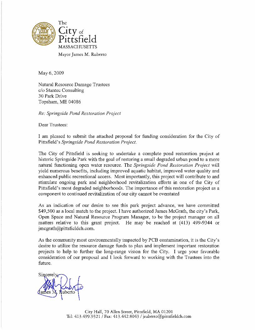
The City of Pittsfield is seeking to undertake a complete pond restoration project at the National
Register listed historic Springside Park. With the goal of restoring a small degraded urban pond
to a more natural functioning open water resource, the Springside Pond Restoration Project will
yield numerous benefits, including improved aquatic habitat, improved water quality and
enhanced public recreational access. This will be a multi-year, multi-phase project that will also
include efforts to address previously identified areas within the Springside Pond drainage area
that are known to contribute to the erosion problems that have negatively impacted the pond.
Once realized, these environmental restoration actions will contribute to and stimulate ongoing
park and neighborhood revitalization efforts in one of the City of Pittsfield’s most degraded
neighborhoods.
PART C. PROJECT NARRATIVE
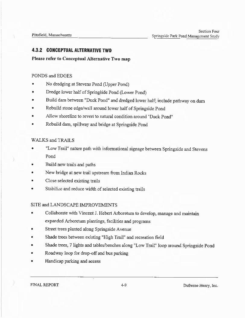
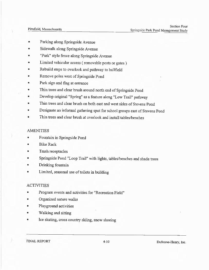
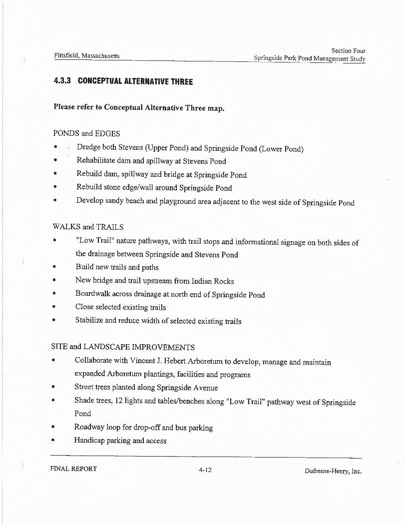
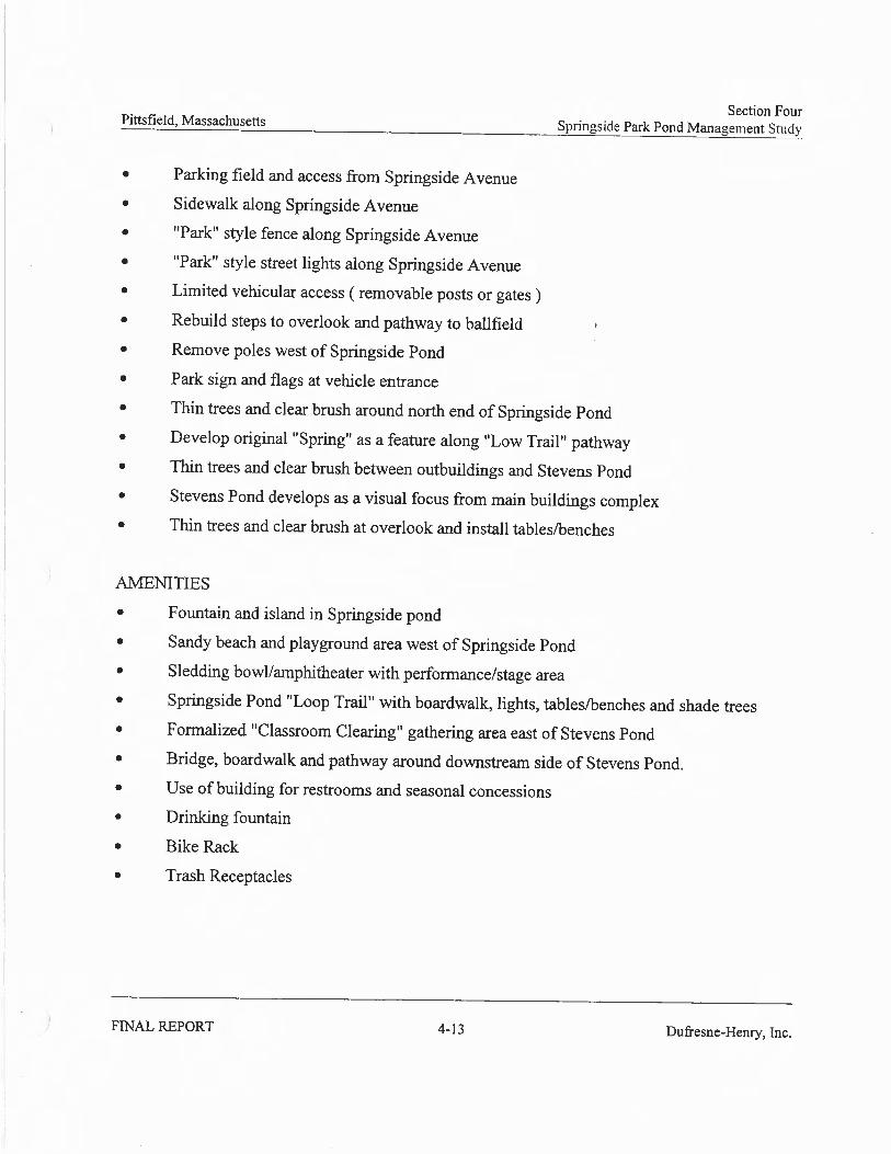
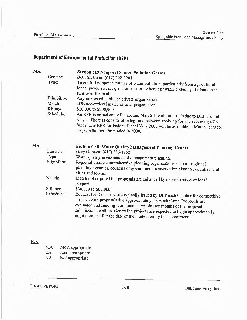
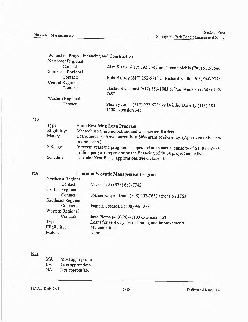
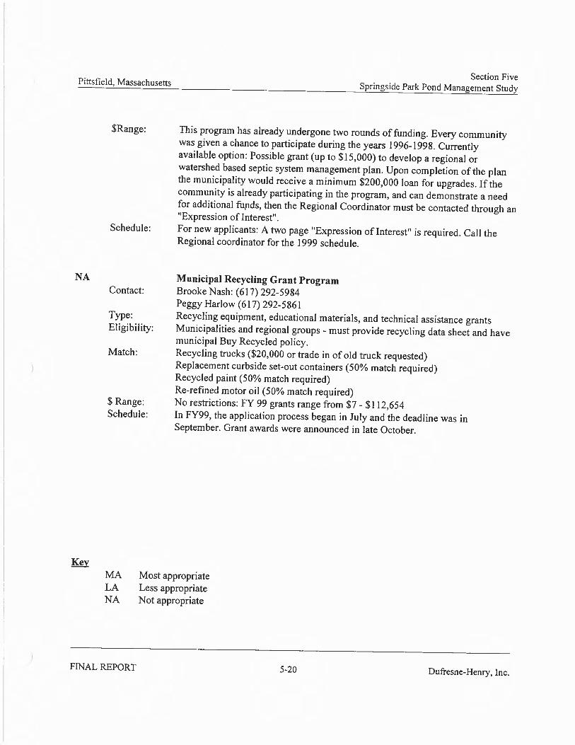
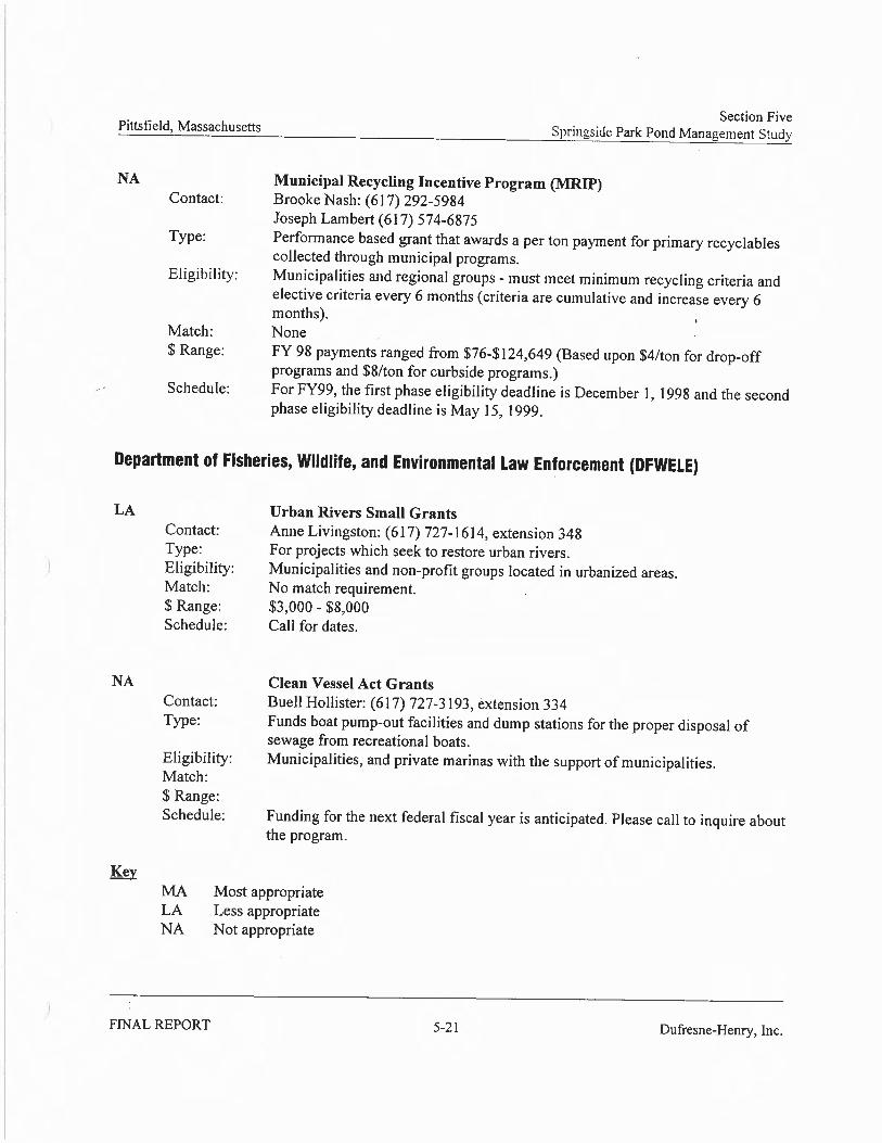
1. Project Goals and Objectives
The primary goal of the Springside Pond Restoration Project is to restore a small degraded urban pond to a more natural functioning open water resource which will lead to improved aquatichabitat, improved water quality and enhanced public recreational access. Through integrated management of stormwater within the watershed and correction of known erosion areas, combined with pond restoration activities, the Springside Pond can once again become acommunity asset within Pittsfield’s largest municipal open space, Springside Park.
2. Project Benefits
The proposed project to restore the Springside Pond will yield the following benefits to natural resources and/or the services they provide:
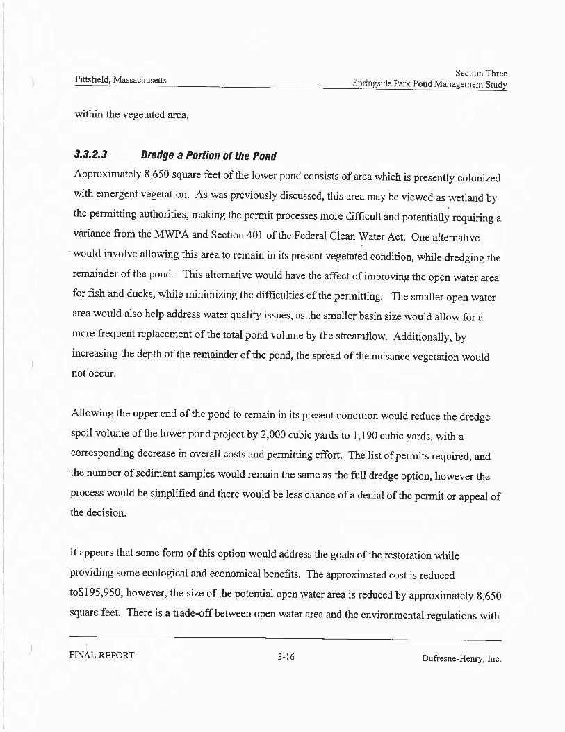
Aquatic Habitat Benefits: Currently the pond is in a severely degraded condition. Water depth isseverely reduced due to the excessive sediment volumes and a breach in the dam. Large algae blooms occur each summer due to the presence of nutrient rich sediments. Since 1967, the openwater extent has been reduced by nearly 1 acre. Implementation of corrective measures to reduce erosion in the watershed and dry-dredging of the pond will greatly improve aquatic habitat values.
Water Quality Benefits: The current water quality at the pond is presumed to be low. Erosion within the watershed along with the lack of an appropriate settling basin at the inlet has caused nutrient rich sediments to course unchecked into the pond, completely filling in much of thenorthern end of the pond and causing seasonal algae blooms in the rest of the pond. Corrective measures to reduce erosion and pond dredging and restoration, along with installation of an appropriate pre-treatment BMP, will lead to improved water quality. This is especially importantas outflow from Springside Pond directly discharges into Silver Lake, a waterbody that is the focus of a major clean up proposal.
Recreational Benefits: Currently, the Pond provides minimal recreation benefit and is extremelyunderutilized as a recreational resource. The seasonal algae blooms are unsightly to neighbors and park users, and a foul odor emanates from the Pond during periods of low flow, caused in part from the leaking dam which exposes portions of the pond bottom. It is anticipated that actions resulting from the restoration of the Pond will improve the recreational opportunities where the public can once again utilize the pond for wading, fishing, or simple quiet reflection.
Additional benefits include:
Environmental Awareness Benefits: Though the pond is a very visible element with the Park, there is generally low or poor awareness of the importance of the pond by the residents in the neighborhood and residents generally consider this pond a liability rather than an asset. It is anticipated that actions resulting from the restoration of the Pond will foster improvedenvironmental awareness of the park and pond through community and neighborhood sponsored events or activities such as pond clean-ups or other events at the park.
1
Community Revitalization and Social Benefits: The Morningside Neighborhood is beset by numerous problems, including absentee landlords, numerous vacant and abandoned lots and buildings, poorly maintained buildings, a perception of the neighborhood as being unsafe and general trash and lack of care. The City of Pittsfield has been conducting a comprehensiveNeighborhood Planning Program. It is anticipated that actions resulting from the restoration of the Springside Pond will continue to stimulate neighborhood revitalization efforts, helping toinstill a sense of pride in the neighborhood.
Historic Preservation: Springside Park was listed on the National Register of Historic Places in2008. The current pond and dam structure, built in 1919, are cited as significant historical contributing elements within the park. Restoration of the pond and the associated dam and retaining wall will help to preserve the historic role that the park and pond played in the early development of this and other parks in the City.
3. Project Implementation Plan
Description of Current Conditions
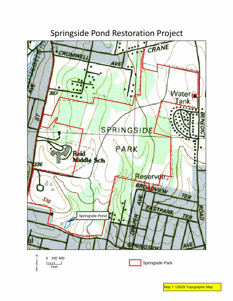
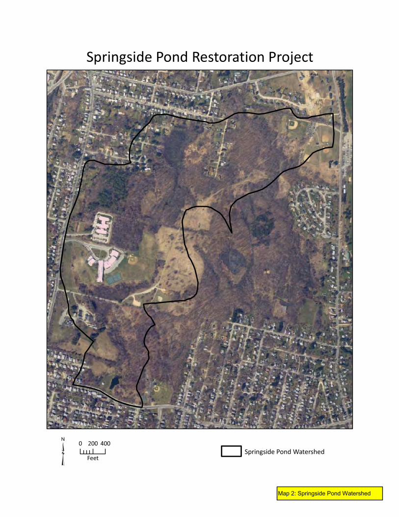
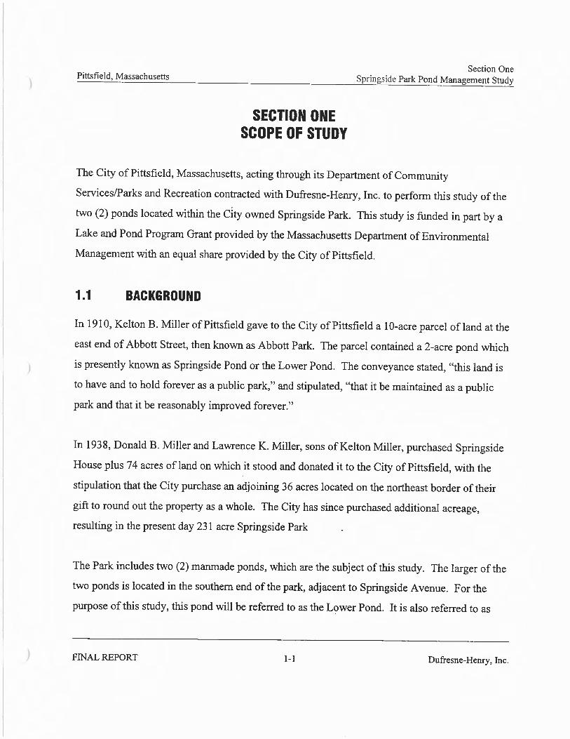
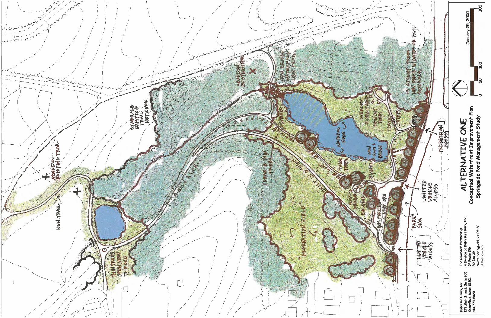
Constructed in the late 1890’s and enlarged to it’s current configuration in 1919, Springside Pond is currently a 0.5 acre shallow water body of irregular shape that lies along an intermittentstream that travels southerly through Springside Park, Pittsfield’s first and largest public park.Situated north of Springside Avenue near the intersection of Pine Street, the pond lies within the primarily undeveloped watershed of Springside Park. The contributing watershed isapproximately 206 acres and consists mostly of sloping wooded terrain with some open grassy and/or brushy areas. (See attached Maps 1 and 2)
A low cut granite and limestone retaining wall, topped with a concrete cap, once bordered the entire pond. Currently, it is severely deteriorated and in many areas has fallen into the pond. A portion of the pond bottom has a concrete cap layer, a remnant from the time when a portion ofthe pond was used as a public wading pool. A granite and limestone dam, outflow structure, and arched footbridge at the lower end of the pond are also deteriorated and the intended water level in the pond cannot be maintained due to leakage through the dam and spillway. Outflow fromthe pond travels a very short distance overland, through a deteriorated swale, to a catch basin where it is then piped underground over 1/2 mile to the northwest corner of Silver Lake where it is discharged.
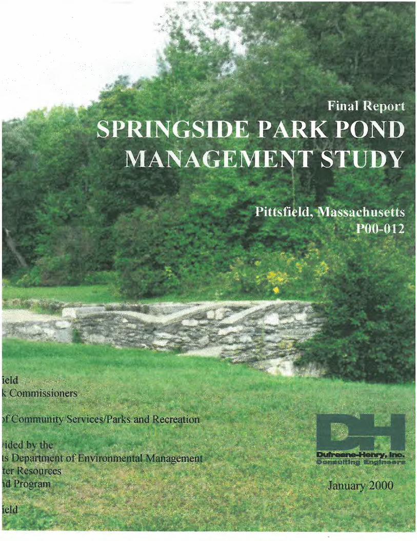
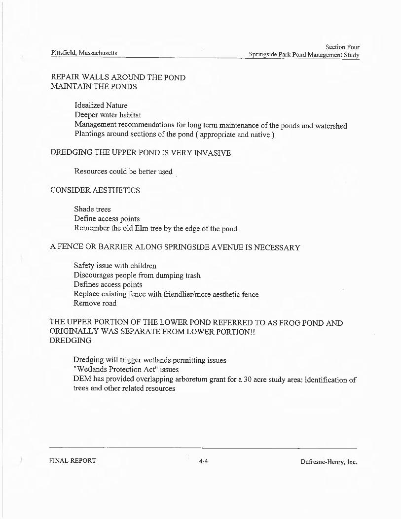
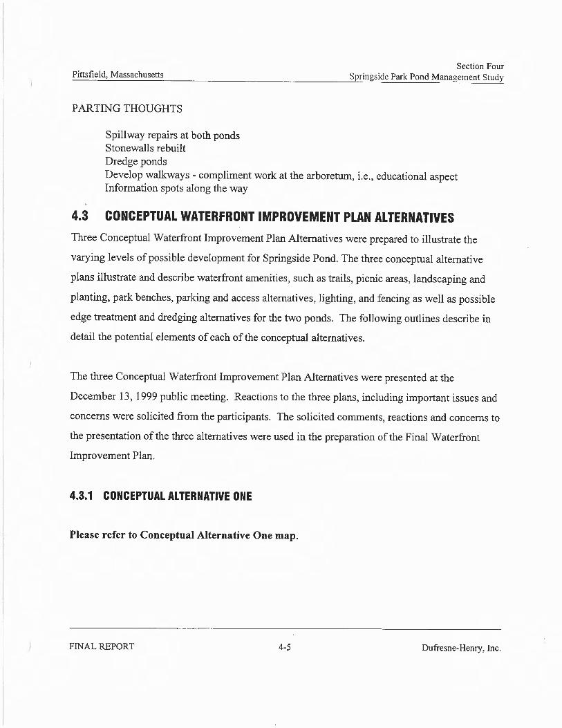
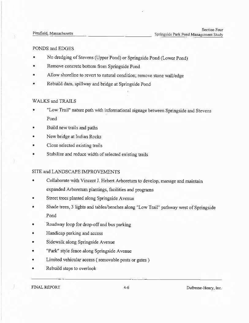
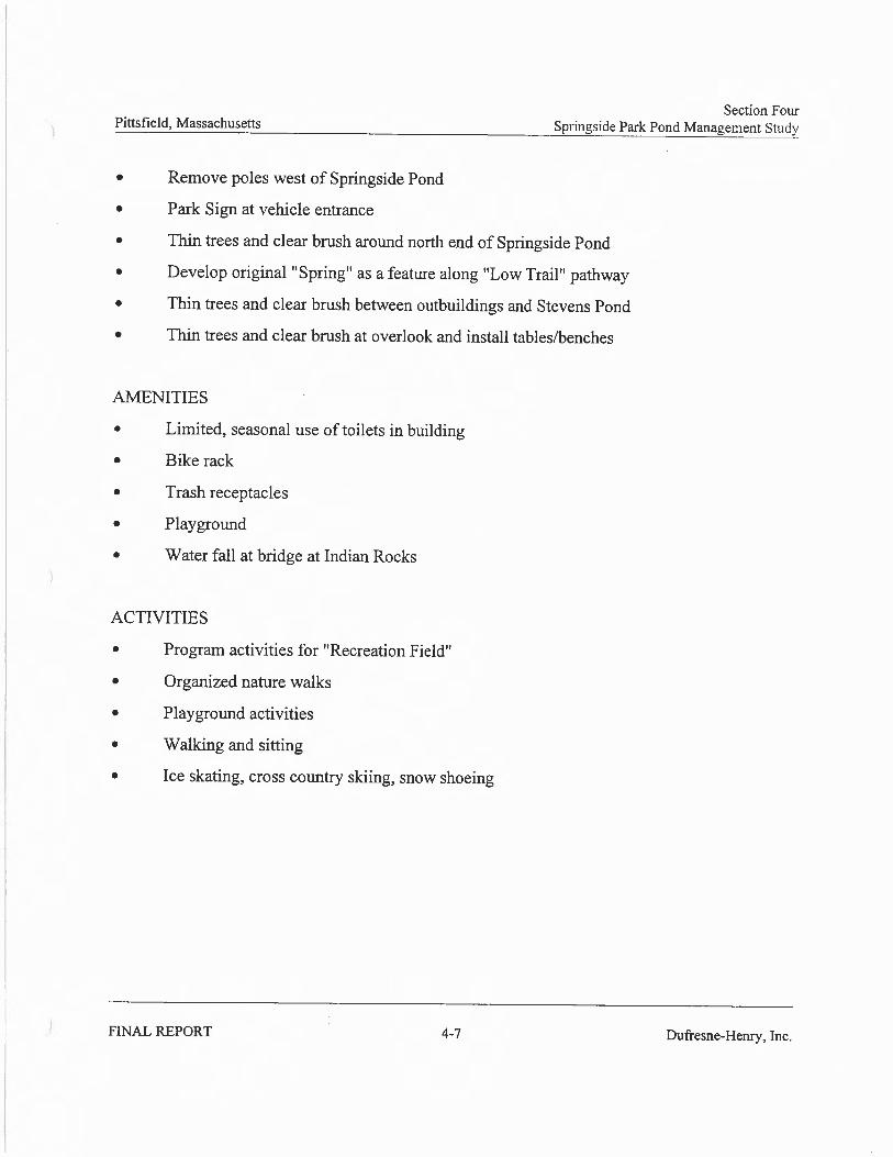
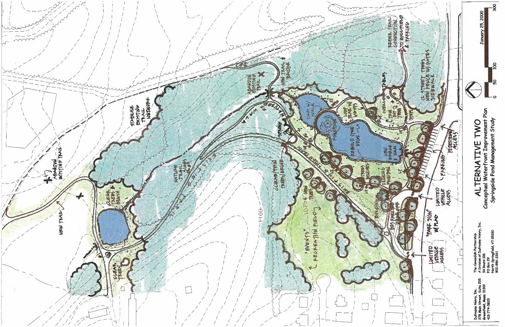
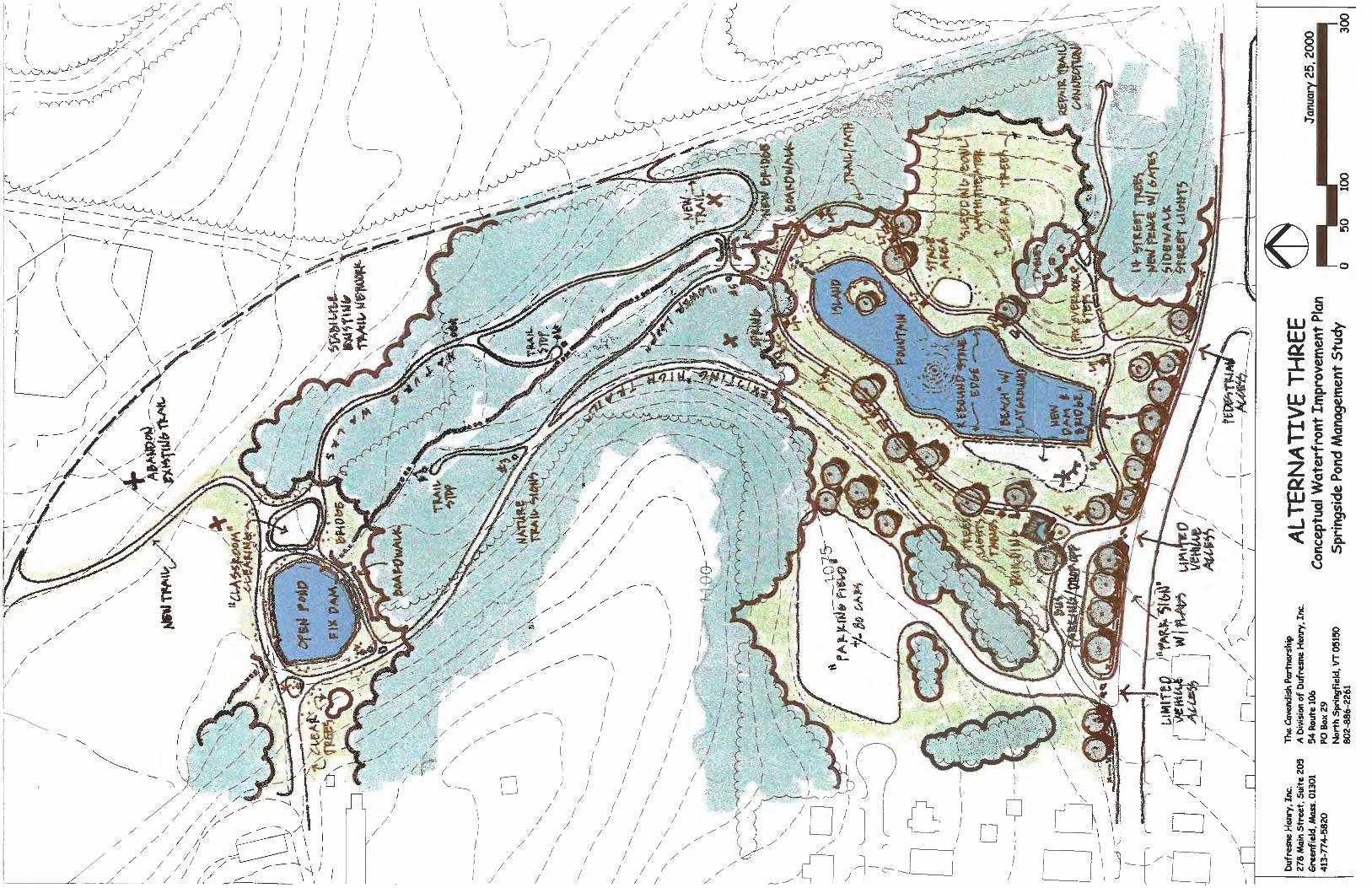
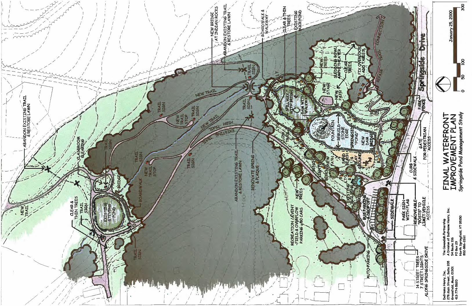
In 2000, the Springside Park Pond Management Study (Dufresne-Henry, Inc.) was completed.This study analyzed the drainage area of the pond and found several keys areas where erosion was taking place within the park (primarily along paths and roadways) which directly contribute to the siltation problems being experienced in the pond. The study also detailed pond restoration strategies, outlined permitting requirements, and developed estimates of probable cost.
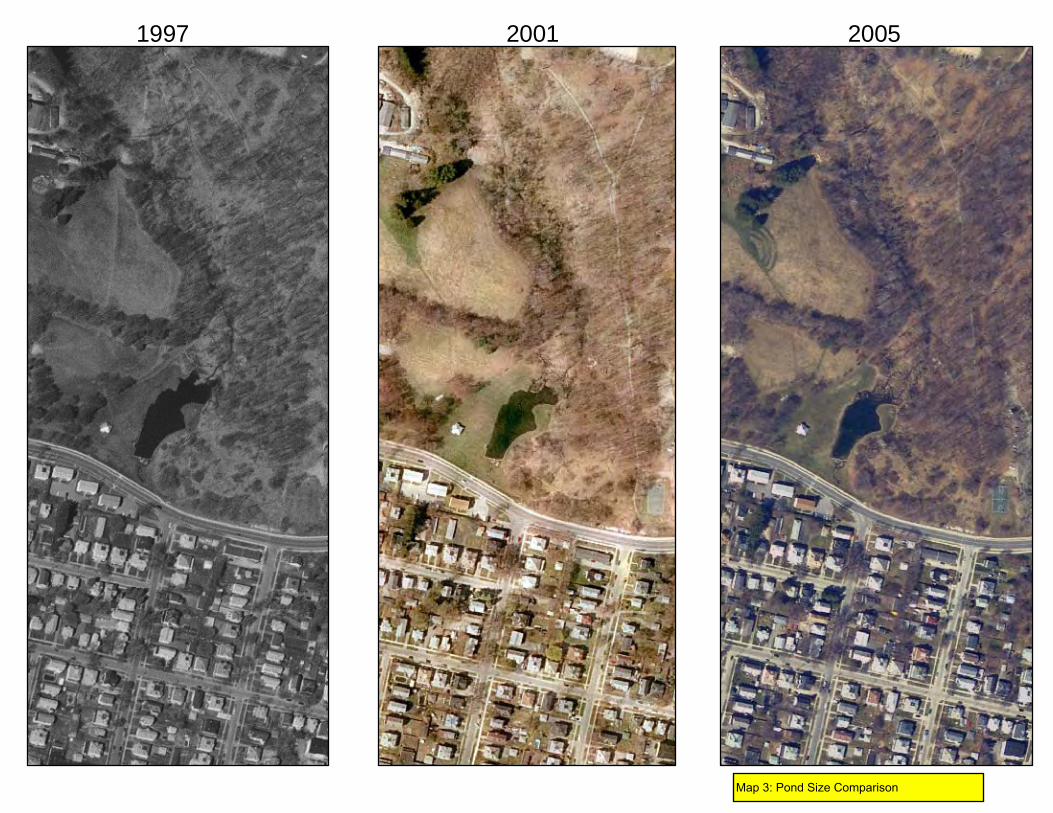
Over the years, it has become heavily silted in leading to diminished water quality and habitatvalue, as well as diminished recreational value. Currently, sedimentation has filled the northern end of the pond, considerably reducing its size. Estimates of sediment build up from 2000 revealed that approximately 3,200 cubic yards of material could be removed during a restoration project. Of particular note is that in 1997 the pond contained .68 acres of open water and in 2005
2
the pond lost over ¼ acre of open water, to a size of 0.5 acres. (See Map 3, Pond Size Comparison)
This pond has a rich history of providing four-season recreation for city residents. For manyyears, the pond was the site of a public wading pool in the summer, and in winter was cleared for ice skating. There currently exists a small brick bathhouse to the west of the pond that was constructed in 1951. This bathhouse is severely deteriorated. A review of the building has revealed that it would be more expensive to repair than future benefit would justify.
In 2008, Springside Park was listed on the National Register of Historic Places. The pond was cited as a major contributing element within the park.
Description of Desired Future Conditions
The Springside Pond Restoration Project is an important aquatic resource reclamation project for the City of Pittsfield and the Morningside neighborhood. Through the restoration activities described herein, the environment and community will benefit from a marked improvement in water quality into and through the pond environment which will lead to improved aquatic habitatfor flora and fauna within the feeder stream and pond. Installation/implementation of BMPs and correction of erosion areas within the watershed will limit sediment from coursing into the mainwatercourse through the park and into the pond, also protecting natural resources.
In addition, recreational opportunities at and around the pond will be improved. Aside from theactual pond restoration construction activities and installation of the watershed BMPs, this proposal seeks to install seating benches around the pond as well as to construct an open-air pavilion in the site of the existing bathhouse. Once all of these improvements are realized, it is envisioned that more park users will enjoy the pond area for wading, fishing, or just simple quiet reflection. In the winter months, the city hopes to be able to provide ice skating for the public as it had for many years prior. The city has no plans to promote swimming in this restored pond and will actively discourage that activity.
a.Implementation Approach
In 1999, the City as awarded a MA DEM Lake and Pond grant to develop an integrated approach to restoring the Springside Pond and its associated watershed. The Springside Park Pond Management Study (2000, Dufresne-Henry, Inc.) reviewed key erosion areas within the watershed, outlined benefits to several pond restoration scenarios, outlined permittingrequirements for each, and attached estimates of probable cost to the different schemes. Theoverall approach will be to implement corrective measures outlined in the study at key erosionsites that contribute to the siltation of the pond (following re-examination of these known sites and prioritization based on available resources), and to dry-dredge sediments from the pond and repair the pond dam and retaining wall. The City is eager to implement recommendations fromthat state-funded study that was completed nearly ten years ago.
Following the formalization of a working group to consist of staff from the city Department of Community Development, the city Conservation Agent, and the chairperson from the Morningside Neighborhood Steering Committee, the project will seek to hire through a publicly
3
advertised procurement process a qualified consulting firm experienced with similar size / scopepond restoration projects in Massachusetts.
Consultant tasks would generally include leading an open public meeting to discuss the pond restoration project and associated park improvements that may be a part of the eventual design, review of existing conditions including preparation of a topographic survey, sediment sampling,final design for the pond restoration components, permitting, and pre and post-monitoring.
The eventual restoration project would include installation of a structural BMP (i.e., sedimentforebay/basin or equivalent) at the inlet of the pond, dry-dredging of up to 3,200 cubic yards of sediment within the pond, repair of the existing stone retaining wall that borders the pond (approximately 550 l.f.), repair of the dam, monitoring of natural re-introduction of native aquatic macrophytes and re-introduction and associated monitoring of fish within the restored pond. The channel between the spillway and the culvert inlet would be stabilized to minimizeerosion and the inlet to the culvert crossing Springside Avenue would be lowered slightly toimprove hydraulics. In addition, some modest improvements to the park environment around thepond are proposed, including the installation of benches around the pond and installation of an open air pavilion on the site of the existing bathroom building which is slated for demolition.
The city, using its engineering and park maintenance staff, will lead the efforts to correct issuesat key erosion sites along pathways and roadways by implementing best management practices (BMP’s). Though a number of sites were noted in the Springside Park Pond Management Study, these sites would be re-examined and corrective measures prioritized. Design and permittingwork will be lead by the city engineering department while on the ground installation of the BMP’s will fall to the park maintenance laborers. This city work will be used as a match to the overall project budget.
The overall approach to this project is to define and implement the most environmentallyappropriate watershed and pond restoration technique(s) that meets the restoration goals outlinedin the Natural Resources Damages Assessment, and Restoration Project Selection Procedure.The Department of Community Development will serve as overall administrator of the project.
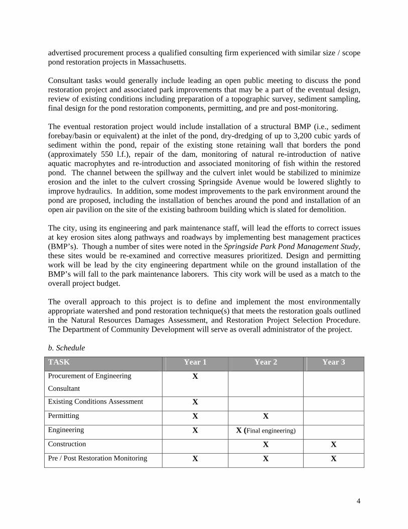
b. Schedule
TASK Year 1 Year 2 Year 3
Procurement of Engineering
ConsultantX
Existing Conditions Assessment X
Permitting X X
Engineering X X (Final engineering)
Construction X X
Pre / Post Restoration Monitoring X X X
4
c. Major Phases and Milestones
Procurement of Engineering Consultant: The working group will develop criteria for the procurement of an engineering consultant and a request for qualifications will be publiclyadvertised by the City. It is envisioned that the city would use criteria such as experience withsimilar restoration projects as the overall basis for designer/consultant selection.
Existing Conditions Assessment: The selected engineer will detail existing conditions within the pond. This would include the completion of a detailed topographic survey which was partially completed in 2008. The condition of the pond retaining wall will also be reviewed. The city engineer will also review with the project team areas of known erosion within the watershed so that sites where corrective measures might be implemented can be prioritized. Following this work, the working group will work with the consultant to host a community meeting where the project will be discussed and additional input can be gathered.
Permitting: Final permitting will follow final engineering design. Numerous permits will berequired based on selected removal/restoration alternative. It is anticipated that the engineer and project team will meet with regulators at pre-permitting meetings to discuss the proposed project.Permitting for the watershed BMP’s, if required, will be performed by the city.
Engineering: Engineering for the pond restoration components will be initiated prior to permitting and following sediment sampling and interpretation of the results. Engineeringdesign will be informed by sediment characterization as well as by a pre-permitting meeting with MA DEP and expectations enunciated through the permitting process. The overall approach is toidentify the alternative that presents the greatest level of restoration for the anticipated cost.Final alternative decision-making will involve the working group.
Engineering for BMP installation within the watershed will be performed by city engineers as part of the match.
Construction: Once permits are in place, the City will advertise the project for public bidding.Construction would occur during the period of lowest flow in the feeder stream, during summermonths. Construction monitoring will be the responsibility of the on-site engineer.Construction of watershed BMP’s will be performed by the city. This ‘construction’ taskincludes construction of the pond restoration activities, watershed BMPs, and also includes installation of several benches around the pond and the installation of an open-air pavilion in the site of the existing bathhouse (which is scheduled to be razed). This task also includes the other associated restoration activities such as fish stocking.
Pre / Post Restoration Monitoring: Monitoring required for the pond restoration project will begin prior to any construction activities, and is anticipated to begin in Year 1. This work will beperformed by a qualified biologist and will include the evaluation of the existing flora and faunaassociated with the project area to identify existing distribution and abundance. Year 2 will
5

include additional monitoring of existing conditions to provide baseline for evaluation ofrestoration benefits. Additional monitoring will carry over into Year 3 and, if required, Year 4.
d. Required Agreements
No access agreements, easements, right-of-way or other agreements are required for this component as all work is within the City-owned Springside Park. Environmental permits and/or regulatory approvals will be required and are outlined in Part D.
e. Long Term Effectiveness and Sustainability
Ponds, especially small urban ones, often degrade due to lack of proper oversight and maintenance. Full restoration of the Springside Pond will re-establish natural, self-sustainingecological processes that will effectively achieve the natural resource goals of the MassachusettsSub Council, and all construction methods for the ecological restoration within the project area will be implemented for the purpose of long-term effectiveness and sustainability. Many of thedetails which will lead to effectiveness and sustainability will be discussed during the manylayers of the required environmental permitting, and it is assumed that conditions will be placedon the proposed project that will reflect the desire to achieve effectiveness and sustainability.Pre-permitting meetings with the various regulatory agencies are anticipated and the outcomes ofthese meetings will additionally inform the most appropriate series of restoration actions.
The project will also require the development of a site-specific Operation and Maintenance(O&M) Plan for the pond which will dictate such matters as timing and execution of clean out of the sediment forebay, monitoring of aquatic species, and periodic dam investigations. It is alsoenvisioned that the O&M Plan will outline criteria to ensure that future land managementactivities will not disrupt areas that will be restored, possibly causing a diminishing of the project’s benefits. These criteria will primarily target park maintenance activities undertaken by the City in the watershed, such as storage of park maintenance materials (gravel, topsoil), culvertclean out scheduling, and snow disposal among others.
f. Coordination and Integration with Other Ongoing or Planned Restoration Activities
Restoration activities at the Springside Pond and watershed will ensure that flow from the Pond will not negatively impact the planned restoration of the hydrologically-connected Silver Lake.
Located immediately to the west of and across Silver Lake Boulevard, Silver Lake currentlyreceives stormwater contributions from several municipal outfalls, including from Springside Pond. In addition to being hydrologically-connected to Springside Pond, Silver Lake is connected to the Housatonic River by a 48-inch diameter concrete conduit located near the intersection of Fenn Street and East Street. This conduit conveys intermittent discharge from Silver Lake and stormwater runoff from Fenn Street and East Street to the Housatonic River.
6
Silver Lake has a history of extensive contamination. PCBs have been detected in the lake'ssediment, bank soils and surface water. Historic discharges of PCBs and other chemicals in process water and wastewater from GE's East Street Area II operations have been reported.
The Consent Decree requires that GE dredge 400 cubic yards of "hot spot" sediment adjacent toone of the historic GE outfalls, clean up contaminated bank soil, and place a cap on the entire bottom of the lake. Bench-Scale Testing and a 1-acre Pilot Study of capping techniques werecompleted in 2006. Sampling of the bank soil should be completed in 2007. Full-scale capping of the Lake is expected to begin in 2010, along with associated bank soil removal.
g. Complementary Planning Efforts
The restoration goals for the Springside Pond are completely complementary with those of otherrestoration and related community improvement initiatives/programs in the watershed. The Springside Park Pond Management Study accompanies this proposal, and the other city documents can be found at www.pittsfield.com.
Springside Park Pond Management Study (2000): In 1999, the City as awarded a MA DEM Lake and Pond grant to develop an integrated approach to restoring the Springside Pond and its associated watershed. The Springside Park Pond Management Study, completed by Dufresne-Henry, Inc. reviewed key erosion areas within the watershed, outlined benefits to several pond restoration / reclamation scenarios, outlined permitting requirements for each, and attached estimates of probable cost to the different schemes.
City of Pittsfield Master Plan Update (2009): The City recently completed a 2-yearcomprehensive update of an outdated Master Plan. This plan calls for the improvements in all areas of civic affairs: transportation, housing, economic development, and the environment.With regards to environmental improvement, the Plan’s primary goals are the preservation and maintenance of natural resources and ensuring adequate funding for park improvement projects.
City of Pittsfield Open Space Plan Update (2009): Beginning in 2006, the City began acomprehensive update of the Open Space and Recreation Plan (OSRP), with funds provided bythe Executive Office of Environmental Affairs, Smart Growth Technical Assistance Program. This effort involved an extensive citywide public process to determine resident’s opinions about natural resources. The first goal identified in the plan is “Protect, preserve and maintain naturalresources to ensure an adequate amount, variety, and distribution of open space and water resources to maintain biodiversity and provide benefit to the public.” The project being proposed is directly in line toward meeting that goal.
Morningside Neighborhood Action Plan (2006): This plan, developed primarily by the residents of the neighborhood, proposes specific steps to improve the quality of life in the Morningside neighborhood. The Pittsfield Community Development Department is currently implementingnumerous goals contained in the plan. The pond at Springside Park was cited as one of the neighborhood's chief assets. The plan recommended restoring this pond to a more natural condition. The proposed project is directly in line toward meeting that neighborhood goal
7
American Institute of Architects (AIA), Sustainable Design Assistant Team (SDAT) Program Plan (2005.) This plan, prepared by a team of nationally renowned planning experts recognized that Pittsfield’s “rivers and lakes are key assets and the backbone of the community.”Recommendations emphasized natural resource strategies that focus heavily on “connecting existing parks and green space.” This Plan further recommended enhancing water quality and riparian areas and utilizing proactive stormwater strategies for site development, including best management practices. This proposal will implement recommendations from some of the foremost planning experts in the country.
Housatonic River Restoration Plan (1999): This Plan, prepared through an extensive publicparticipation planning process, recommends improvements to water quality for point and nonpoint sources. This proposal will help accomplish the recommendations established in the Housatonic River Restoration Plan.
4. Technical/Technological Feasibility
4a. Brief descriptions of the methods to be used to conduct the major tasks
This restoration project can be viewed in three parts: Permitting/Engineering, Construction, andMonitoring. None of these components proposes the use of innovative techniques to achieve the overall restoration goals. In fact, the project components can each be viewed as commonplace in the larger realm of ecological restoration.
Permitting and engineering for the pond component will be performed by a publicly procuredand qualified consultant. Overall tasks under this component include establishment of baselinedata sets, topographic surveys, and design engineering. These tasks will occur in year one of the project, with engineering design a result of pre-permitting meeting with environmentalregulators. Permitting and engineering for the watershed BMPs will be performed by the cityengineering department, and may not occur simultaneous with the pond component for permitting and engineering.
Following successful completion of permitting and public bidding of the construction component, implementation of the pond restoration design will occur during periods of low flow in the feeder stream, with water from the inlet needing to be bypass pumped around the pond to the catch basin near Springside Avenue. It is anticipated that the pond will need to be completely dewatered so that dam and wall repair can proceed in relatively dry conditions.Removal of sediments will precede the masonry component, and it is anticipated that this task will be completed relatively quickly. Sediments may be disposed of on upland city property toreduce trucking and disposal costs. Final desired grades will be achieved within the pondfollowing major sediment removal.
Monitoring will occur before any work is undertaken and will certainly inform permitting and eventual engineering design. Monitoring of the BMPs will follow the STEPL model and will be performed by the project engineer, though monitoring of the aquatic species assemblage pre-and
8
post restoration will be performed by a qualified aquatic biologist using yet-to-be determinedmethods.
4b. Successful use of the approach and / or method
Pond restoration techniques vary based on available budget, the desired outcome and other environmental factors. In the case of the Springside Pond, it is clear that the removal of accumulated nutrient-rich sediments, along with installation of an appropriate pre-treatment Best Management Practice (BMP) such as a sediment forebay, is the best course of action to achievethe desired goals. Pond dredging is an accepted lake management technique that is outlined inthe Generic Environmental Impact Report Eutrophication and Aquatic Plant Management in Massachusetts and a technique that has been employed successfully in other communities acrossMassachusetts. Other statewide examples can be found in the GEIR in Section 2.0. Recommendations outlined in the MA GEIR will guide this particular pond restoration.
Additional restoration actions include re-introduction of aquatic macrophytes and fish species.These associated restoration actions are also commonplace with regards to pond restoration and will be thoroughly conditioned and monitored to achieve a high degree of long-term effectiveness and sustainability.
Erosion issues within the watershed will be addressed through a combination of BMPs, as detailed in the Springside Pond Management Study. BMPs are typically a combination of practices determined to be effective, economical approaches to preventing or reducing pollution generated by nonpoint sources of pollution.
4c. Certainties and uncertainties associated with innovative approaches to the proposed project
No innovative approaches are proposed as part of this restoration project.
4d. Uncertainties regarding the project’s technical/technological feasibility
This project will provide the appropriate amount of engineering detail and the Sub-Councilprocess of project implementation allows for an adaptive management approach to address cooperatively and effectively any unexpected issues or complications. Having said this, the proposed project described herein is not one that is technologically complex. Pond restoration /reclamation, dam repair, and installation of BMP’s to correct erosion issues is fairly commonplace technology that has been proven across the country in numerous applications.
One area of uncertainty relates to the characterization of the accumulated sediments within thepond. A review of former land use activities within the immediate watershed area have revealed that the watershed is and has been undeveloped as the vast majority of it has been in parkland foryears. One can surmise that the issue of contaminated sediments should not be an issue, but this can only be resolved following an evaluation of the sediments. This uncertainty regardingcharacterization of sediments would not pose any technical concerns (other than change in the
9
way the contaminated sediments are handled and disposed of), but more practically budgetary concerns.
4e. Potential technical / technological complications
The proposed project is not one that is technologically complex and as such few complications are envisioned. The City staff and staff from the City’s selected, qualified consultant will bringexperience and local expertise that will allow for an adaptive management approach to addresscooperatively and effectively any unexpected issues or complications.
5. Monitoring/Evaluation and Contingency Plan
This restoration project will deliver tangible, specific ecological results that are identifiable andmeasurable, and will be evaluated by professionally accepted methods so that restoration activities can be documented and evaluated. As required, the project proposes to monitor one structural and one functional parameter to provide an objective evaluation.
STRUCTURAL PARAMETER: BMP Effectiveness
The various BMPs that will be implemented within the watershed (following NRD Trusteeapproval), as well as the BMP scheduled to be installed at the inlet of the pond, will be evaluated pre-and post installation using the MA DEP accepted STEPL model. The Spreadsheet Tool for Estimating Pollutant Load, or STEPL, applies simple algorithms to calculate nutrient andsediment loads from different land uses and the load reductions that would result from the implementation of select best management practices (BMPs). STEPL computes watershed surface runoff, sediment delivery, 5-day biological oxygen demand (BOD5) and nutrient loads,including nitrogen and phosphorus based on various land uses and management practices. STEPL calculates the annual nutrient loading based on the runoff volume and the pollutantconcentrations in the runoff water as influenced by land use distribution and managementpractices. Through STEPL, the annual sediment load is calculated based on the Universal Soil Loss Equation (USLE) and the sediment delivery ratio. The sediment and pollutant load reductions that result from the implementation of BMPs were computed using the known (default) BMP efficiencies. Eventual target values are not being proposed here.
The STEPL program focuses on the following pollutants. Total Suspended Solids (TSS) are solids in water that can be trapped by a filter. TSS can include a wide variety of material, such as silt, decaying plant and animal matter, and wastes. Stormwater runoff may pick up particles as it flows over the ground, or from erosion within the sub watershed. These sediments usually stay ‘suspended’ in the flow and do not settle out until the flow slows down, usually within a waterbody. TSS loading can lead to excessive sedimentation, transportation and deposition of excessive nutrients, and clouding of water reducing light penetration.
10

Total Nitrogen is usually contributed to waterbodies from the over application of fertilizers, atmospheric deposition, or runoff from excessive agricultural farming practices. Excessive TN can lead to algal blooms within waterbodies reducing water quality and dissolved oxygen levels.
Total Phosphorous (TP) includes both the amount in solution and also in particulate form.Phosphorus comes from many diffuse sources including erosion, agricultural drainage, wastewater, industrial discharges, fertilizers, and household cleaners. Phosphorous can contribute to the eutrophication of surface waterbodies.
5-day Biological Oxygen Demand (BOD5) is the rate of oxygen uptake by micro-organisms in asample of water over an elapsed period of five days. BOD is not an accurate quantitative test,although it can be considered as an indication of water quality. Higher BOD can indicate low dissolved oxygen levels and be harmful to aquatic species.
FUNCTIONAL PARAMETER: Native aquatic macrophytes
A major benefit to the restoration activities proposed herein relates to the improvement of thehabitat and water quality value for native aquatic plant species. This project proposes pre-and post monitoring of the aquatic assemblage to determine successful restoration, to be performedby a qualified aquatic biologist. The project does not propose the physical re-introduction of aquatic macrophytes in the Springside Pond. Rather, the project will evaluate the natural re-growth of aquatic species.
Aquatic plant monitoring will be performed using accepted field methods, and will be performedduring each of the three years of the project schedule. If funded, the project team will develop a more detailed monitoring program as a part of the permitting processes. The small size of the pond means that a complete aquatic vegetation survey can be performed with great accuracy. Success will be gauged based on whether natural re-colonization of native aquatic plants occurs.
11

6. Qualifications of Applicant and Project Team
a. Technical Capacity
See attached curriculum vitaes for the primary project personnel:� Deanna Ruffer (AICP): Pittsfield Director of Community Development� James McGrath: Pittsfield Park Open Space & Natural Resource Program Manager � Caleb Mitchell: Pittsfield Conservation Agent
b. Administrative Capacity
Overall project administration will be the responsibility of the City of Pittsfield Department of Community Development. Community Development Director Deanna Ruffer (AICP) and JamesMcGrath (Park, Open Space, and Natural Resource Program Manager) have years of variedexperience managing planning and construction projects of similar size and complexity, and theiroffice is well staffed to administer such grants.
Outside technical expertise will need to be sought early in the project. Through a formal public procurement process, the City will seek to retain a qualified consulting firm with experiencedesigning and managing pond restoration projects of similar size and scope within Massachusetts. The city will seek to retain a consultant with experience in administering large and complex construction projects.
7. Supporting Technical Documentation
Please refer to the following, which are attached to this project proposal:
Springside Pond Dam Rehabilitation: Evaluation of Alternatives. Technical Memorandumprepared by SEA Consultants (2008)
Springside Park Pond Management Study. Dufresne Henry, Inc. (2000)
12
PART D. ENVIRONMENTAL AND SOCIOECONOMIC IMPACTS
1. Impact Checklists
See attached completed checklists
2. Impact Narrative
Air quality impacts: The project may increase potential for release of pollutants to ambient air from dust associated with the construction activities at the pond and dam, as well as short-term emissions from construction vehicles at the site. Best construction practices will be employed to reduce the impacts to air quality. This may include watering down of the construction accessroad during especially hot and dry days and reducing idling times of construction vehicles.
Instream flow impacts: Instream flow from the outlet of the pond will need to be altered during the dam removal and re-construction phase, causing minimal short-term impacts to aquatic life.Over the long term, though, instream flow in this location will be restored and this will benefitaquatic life such as macroinvertebrates. Permits will be required which detail how these impactswill be mitigated, such as a local Orders of Condition.
Surface water quality impacts: The pond restoration project may have significant adverse impacts to surface water quality in the form of increased turbidity during the construction phase.Though, through the permitting process, measures will be outlined that will control turbidityduring construction. Such measures will be further developed once the preferred restoration alternative is chosen. In the long term, the pond restoration project will result in beneficialimpacts to surface water quality. Permits will be required which detail how these impacts will mitigated, such as MEPA Review by Secretary of EOEA and state water quality certification.
Sediment quality impacts: There is a great amount of sediment that has collected within the pond. During construction, methods will be employed to reduce the chance of (potentiallycontaminated) sediment escaping ‘down river’, but flows will still need to be maintained. Oncethe sediment is removed and the short stream stretch below the dam restored, upstream sedimentflow will be restored to a more natural process, aided by the installation of a constructedsediment forebay. Permits will be required which detail how these impacts will mitigated, suchas MEPA Review by Secretary of EOEA and permits from the Army Corps of Engineers for sediment removal.
Soil quality impacts: The buffer zone of the pond will be impacted during construction, causing short-term impacts in the form of soil erosion. Pre-construction activities will require adequateerosion control, so soil erosion should be minimal and if erosion does occur it will not have the opportunity to migrate out of the project area. Permits will be required which detail how these impacts will mitigated, such as through the local wetland permitting process.
Groundwater quality impacts: Though there may be short-term impacts to ground water quality, it is believed that through the removal of nutrient rich sediment within the pond, groundwater will no longer be interfacing with this sediment, producing benefits to groundwater
13

quality. Permits will be required which detail how these impacts will mitigated, such as MEPA Review by Secretary of EOEA.
Wetlands quality and services: The current preferred option for pond restoration envisions thatthe area in the north end of the pond, which appears to be functioning as a Bordering Vegetated Wetland (BVW), be removed during the dredging process to increase the amount of open waterto that of the historical size. In this case, there would be a permanent loss of wetlands. Though, overall the pond restoration project will provide numerous other benefits to this wetlandecosystem such as water quality and aquatic habitat improvements. Permits will be requiredwhich detail how any wetland impacts will be mitigated, such as MEPA Review by Secretary of EOEA.
Diversity and abundance of aquatic species: The project may influence the population and diversity of aquatic species during the construction period. Though, pre-construction monitoring will detail these populations and efforts will be made during construction to allow for migration.Post-construction monitoring will also be required, and it is believed that restoration of the pond to a more natural system will improve both the population and diversity of resident aquatic species. Permits will be required which detail how these impacts will mitigated, such as MEPA Review by Secretary of EOEA.
Diversity and abundance of terrestrial wildlife species: Construction will produce short-termdisruption to resident species such as great blue heron and deer, both of which have been observed in the immediate project area. It is believed that such species will move out of the construction area during the relatively short time span required for construction without negativeimpacts to them. Long term, terrestrial species will benefit from a restored pond system that has cleaner water and a more native assemblage of plant, tree, and shrub species. Permits will be required which detail how these impacts will mitigated, such as MEPA Review by Secretary of EOEA.
Diversity of plant communities: Aquatic and terrestrial plant species will be impacted duringconstruction activities. Some pond bank plant species may not survive the construction activities. Some shrub and tree species may be deliberately removed, such as alien non-natives.Appropriate aquatic plant species may be re-introduced if warranted. Permits will be required which detail how these impacts will mitigated, such as MEPA Review by Secretary of EOEA.
Impacts on local sense of community and well-being: This project will have a beneficial impact to the local sense of community and well-being. Springside Park improvements are a priority for the City and especially for the residents of the Morningside neighborhood, and pond restoration is a high priority goal. The pond restoration project will foster feelings that local government is responsive to the community desires and will also improve the perception that the pond is completely polluted.
Impacts on aesthetics: During construction, there will be adverse impacts due to the fact that it will look very much like a construction site. In the long term, though, with the dam reconstructed and the pond restored to a more natural look, residents will seek out this spot for quiet reflection.
14
Impacts on public health or safety: Children are often observed playing near the pond, and sometime wading in the pond. The depth of sediment makes this a dangerous situation. Removal of the sediments, especially if they are found to be contaminated, will create abeneficial impact to public health and safety.
Impacts on recreational activity: The current Springside Pond site provides little in the way of quality recreational enjoyment. Wading is nearly impossible and the fishing quality is limiteddue to the high amount of sediment and poor water quality. With the pond restored, the quality of water based enjoyment will be improved greatly. In addition, with the addition of an open-airpavilion and bench seating around the pond, simply enjoying the pond ecosystem will be greatly enhanced.
Impacts on education: There will be positive impacts to educational opportunities with thisproject.Locally, educators may wish to use the site as a component to their environmental curriculumwith the topic of pond life. The site will include a new open air pavilion with picnic tablessuitable for classroom exercises. More importantly, though, this restoration project will providean opportunity for technology transfer to other communities who are exploring erosion controlalong paths and roadways and pond restoration. In fact, this restoration project could constitute a well publicized case study.
Impacts on local partnerships and collaborative efforts: The pond restoration project involves several local partners and has been previously outlined in the project narrative. Through such cooperation, the restoration project outcome will be improved.
Nuisance impacts: The pond site is often perceived as a nuisance to the local neighborhood rather than an asset, especially in the past several years when since the dam has been notfunctioning and the pond isn’t holding its normal water level. During periods of low flow, the pond is overtaken by unsightly algae which, when it decomposes, produce an offensive odor. Pond restoration will reduce the nuisance elements that currently exist.
Short-term commercial economic impact of restoration action: The pond restoration and dam reconstruction will produce benefits to the local economy through employment in theengineering and construction trades.
Impacts on property values: The pond restoration project will improve the market rate of the adjacent properties.
Impacts on recreational expenditures and related businesses: The restored pond will produce positive benefits to retail businesses that rely on healthy water bodies, namely those that sellfishing equipment.
15
16
3. List of Permits and/or Regulatory Approvals that are required to complete the project
The list below represents the specific types of ‘Approvals or Permits Required’ for the dredging and pond restoration. Please refer to the Impact Checklist Narrative for specifics regarding which permits would be needed for which activities. Please be aware that at present no permits have been secured for this project. This list may or may not be complete, and may change based on the actual restoration design and proposed impacts.
Local� Wetlands Protection Act Order of Conditions - Pittsfield Conservation Commission
State� MEPA Review (Environmental Notification Form) � Environmental impact reporting (EIR if needed) � Dredging permits (MA DEP Ch 91) � Aquatic Structures permit (MA DEP Ch 91) � Water Management Act (diversion/use permit) � Clean Water Act Section 401 (MA DEP WQ Certification) � Clean Water Act Section 404 (USACE wetlands statue) � Dam Safety/alteration permit (MADCR) � Waste disposal permit (MADEP)

The MA Sub Council will review the information provided and determine whether further information is required.
CHECKLIST: POTENTIAL ENVIRONMENTAL AND SOCIOECONOMIC IMPACTS
Project Name: Springside Pond Restoration Project
Applicant: City of Pittsfield
ImpactCategory Impact No Effect
MinimalAdverseImpacts*
SignificantAdverseImpacts*
BeneficialImpacts*
MitigationRequired*
Permit or Approval
Required**Air quality impacts X
Instream flow impacts X X X
Surface water quality impacts X X X
Sediment quality impacts X X
Soil quality impacts X X X
Groundwater quality impacts X X
Wetlands quality and services X X XDiversity and abundance of aquatic species X X
Diversity and abundance ofterrestrial wildlife species X X
Diversity of plant communities X X
Env
iron
men
tal
Other:
Other:
17

The MA Sub Council will review the information provided and determine whether further information is required.
CHECKLIST: POTENTIAL ENVIRONMENTAL AND SOCIOECONOMIC IMPACTS
Project Name: Springside Pond Restoration Project
Applicant: City of Pittsfield
ImpactCategory Impact No Effect
MinimalAdverseImpacts*
SignificantAdverseImpacts*
BeneficialImpacts*
MitigationRequired*
Permit or Approval
Required**Impacts on minority or low incomepopulations X
Impacts on local sense of communityand well being X
Impacts on aesthetics X X
Impacts on public health or safety X
Impacts on recreational activity X XImpacts to Native American Trust Resources X
Impacts on non-Tribal cultural sites X
Impacts on education X
Impacts on local partnerships and collaborative efforts X
Impacts on availability and quality of drinking water X
Impact on subsistence activity X
Nuisance impacts X
Soci
al
Other:
18

The MA Sub Council will review the information provided and determine whether further information is required.
CHECKLIST: POTENTIAL ENVIRONMENTAL AND SOCIOECONOMIC IMPACTS
Project Name: Springside Pond Restoration Project
Applicant: City of Pittsfield
ImpactCategory Impact No Effect
MinimalAdverseImpacts*
SignificantAdverseImpacts*
BeneficialImpacts*
MitigationRequired*
Permit or Approval
Required**Short-term commercial economicimpact of restoration action X
Impacts on property values X
Impacts on recreational expendituresand related businesses X
Impacts on existing resource-basedindustries X
Impacts on commercial water users X
Impacts on river-based commercialnavigation X
Impact on wastewater dischargers X
Other:
Eco
nom
ic
Other:
* Requires narrative discussion; see instructions in text.** List and description of permits required; see instructions in text.
19

PART E PROJECT BUDGET
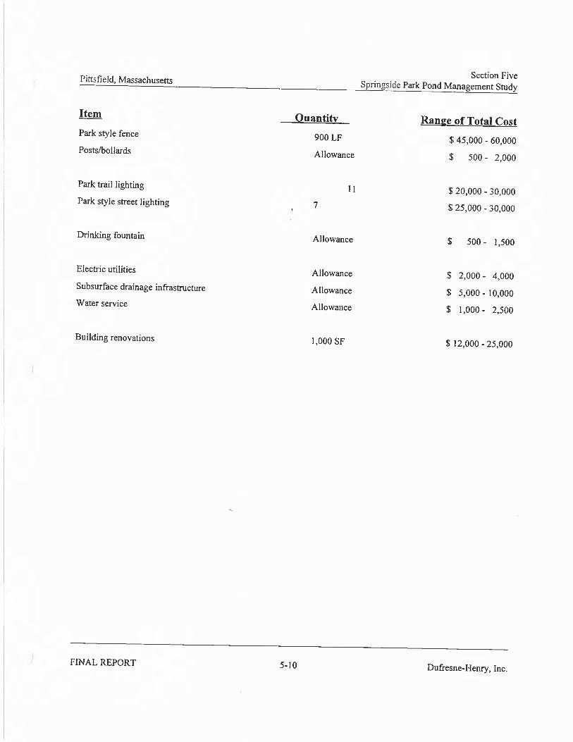
1. Project Budget Tables: See Table 1 and Table 2 that follow.
2. Budget Narrative.
The ‘Springside Pond Restoration Project’ totals $654,500. Of this overall project cost, a total of $605,000 is respectfully requested through the Natural Resource Damage Trustees to assist with the Project. A total of $49,500 is being committed by the City of Pittsfield, with $24,500 of thisas a cash match and the remaining $25,000 as in-kind labor match spread out over various city-assigned tasks.
The City of Pittsfield has been very thorough in the development of the attached budget and is confident that the estimates shown are accurate and reflective of true costs. During the proposedproject development stage, the Pittsfield Conservation Commission voted to authorize City staff the use of $2,000 toward the development of estimates of probable cost. The City hired SKDesign Group to develop these estimates which reflect very current costs associated withpermitting, engineering, and construction.
Task A. Procure Engineering Consultant: This task includes $5,000 that the City has committed to the project and is shown as an in-kind labor match. The City will seek to procurethe services of a qualified engineering consultant to assist with the Springside Pond Restoration Project. This cost is shown as an in-kind contribution and will cover the city staff time of the City’s Procurement Officer and primary project team from the Office of CommunityDevelopment. This task is shown as a Year 1 task.
Task B. Existing Conditions Assessment: This task is shown at $5,000 that the City is seekingNRD funds to cover for the costs of the preparation of an existing conditions assessment. The majority of the assessment work has already been performed under two separate projects. Under the Springside Park Pond Management Study which was completed in 2000 under a MA Lake and Pond grant, the city used $25,000 to develop the initial assessment of the pond and watershed. Additionally, the City used $24,000 of Community Development Block Grant funding in 2008 to develop the assessment of the Springside Pond Dam restoration options study(SEA). The NRD funding being requested under this task will be used to re-confirm data that was gathered during these two previous studies as well as to complete the topographic survey which was completed for only one-half of the pond project area in 2008. This task is shown as a Year 1 task.
Task C. Permitting: This task is shown at $70,000. Of this total, the City is seeking $65,000 in NRD funds for the preparation of the numerous permits that will be required for the pond restoration component of the overall project. The City has committed $5,000 as an in-kind labormatch toward this task, as it is envisioned that City project team time will need to be spent
20

during the development of these permits, at pre-permitting meeting and at public hearings. This task is shown as a Year 1 and Year 2 task.
Task D. Engineering: This task is shown at $25,000. Of this total, the City is seeking $20,000 in NRD funds for the preparation of the required engineering plans for the pond restoration component. It is anticipated that engineering will begin in Year 1, with final engineeringcompleted in Year 2 following what will more than likely be a lengthy permitting timeline. This task total also incorporates $5,000 as a City committed in-kind match that will be used towardthe development of engineering details of the watershed BMPs. Constriction of the BMPs is shown as an in-kind labor match in Task E.
Task E. Construction: This task is shown at $534,500. Of this total, $500,000 is being requested through the NRD funding for the pond restoration construction activities previously described. This cost was professionally estimated by SK Design Group during the developmentof this project proposal. Construction costs were shown to be $446,000 with a 12% contingency, rounded up for the purposes of this budget proposal to $500,000.
Additionally, this overall task total includes $10,000 of in-kind city labor toward the correction of erosion problems in the Springside Park watershed at will have been engineering as an in-kind match in Task D. This overall task also shows $24,500 of City committed cash match which willbe used to raze the existing warming house adjacent to the pond. This building contains asbestos as well as an underground storage tank. All activities associated with Task E are shown in theproject schedule as mainly Year 2 activities, with Year 3 shown as a contingency.
Task F. Pre / Post Monitoring: This task is shown at $15,000, the complete amount of which is being requested through the NRD Trustees funding. This task is shown in the project scheduleas being spread out over a three-year project period.
21

TABLE 1 HOUSATONIC RIVER NRD FUNDING ALLOCATION BY STATE FISCAL YEARS *
PROJECT TITLE: Springside Pond Restoration Project
APPLICANT NAME: City of Pittsfield, MA
FISCAL YEAR 1 FISCAL YEAR 2 FISCAL YEAR 3 FISCAL YEAR 4 EXPENSE CATEGORY
Housatonic RiverNRD Funds
Housatonic RiverNRD Funds
Housatonic RiverNRD Funds
Housatonic RiverNRD Funds
A. SALARIES
B. EMPLOYEE BENEFITS
C. CONTRACTED SERVICES $95,000 $505,000 $5,000
D. SUPPLIES, MATERIALS AND EQUIPMENT
E. TRAVEL
F. OTHER (LIST)
G. OTHER (LIST)
TOTAL BY FISCAL YEAR 1 $95,000 2 $505,000 3 $5,000 4
GRAND TOTAL (sum of boxes 1+2+3+4) [This sum is the total NRD fund request and
should match Part A, Budget Summary, Box 1]$605,000
* The state fiscal year is July 1 – June 30. If the proposed project will be completed in one year, fill in only the column titled “Fiscal Year 1.”

TABLE 2 PROJECT BUDGET SUMMARY BY TASK AND FUNDING SOURCE
PROJECT TITLE: Springside Pond Restoration Project
APPLICANT NAME: City of Pittsfield, MA
OTHER CONTRIBUTIONSTASK* HOUSATONIC RIVER
NRD FUNDSCOMMITTED NOT COMMITTED
TOTAL COST BY TASK
A. Procure EngineeringConsultant $5,000 (City in-kind) $5,000
B. Existing ConditionsAssessment $5,000 $5,000
C. Permitting$65,000 $5,000 (City in-kind) $70,000
D. Engineering$20,000 $5,000 (City in-kind) $25,000
E. Construction$500,000 $10,000 (City in-kind)
$24,500 (City cash) $534,500
F. Pre / Post Monitoring$15,000 $15,000
G.
TOTAL BY FUNDINGSOURCE 5 $605,000 6 $49,500 7 8 GRAND TOTAL
$654,500
NOTES: Box 5 should be the same as the Grand Total indicated in Part E: Table 1. Box 6 above should match Part A, Budget Summary, Box 2.Box 7 above should match Part A, Budget Summary, Box 3. Box 8 should match Part A, Budget Summary, Box 4.
* The listed tasks should correspond with information provided in the Project Implementation Plan.

Springside Pond
Springside Pond Restoration Project
Springside Park³ 0 200 400
Feet
Map 1: USGS Topographic Map
Springside Pond Restoration Project
Springside Pond Watershed³ 0 200 400
Feet
Map 2: Springside Pond Watershed
1997 2001 2005
Map 3: Pond Size Comparison

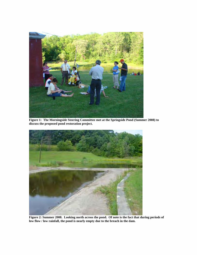
Figure 1: The Morningside Steering Committee met at the Springside Pond (Summer 2008) to discuss the proposed pond restoration project.
Figure 2: Summer 2008. Looking north across the pond. Of note is the fact that during periods of low flow / low rainfall, the pond is nearly empty due to the breach in the dam.
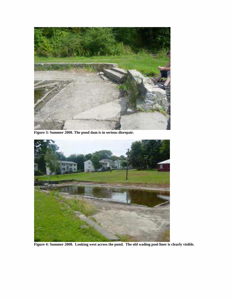
Figure 3: Summer 2008. The pond dam is in serious disrepair.
Figure 4: Summer 2008. Looking west across the pond. The old wading pool liner is clearly visible.
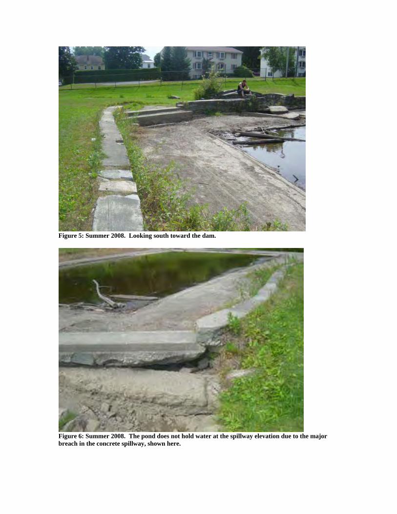
Figure 5: Summer 2008. Looking south toward the dam.
Figure 6: Summer 2008. The pond does not hold water at the spillway elevation due to the majorbreach in the concrete spillway, shown here.
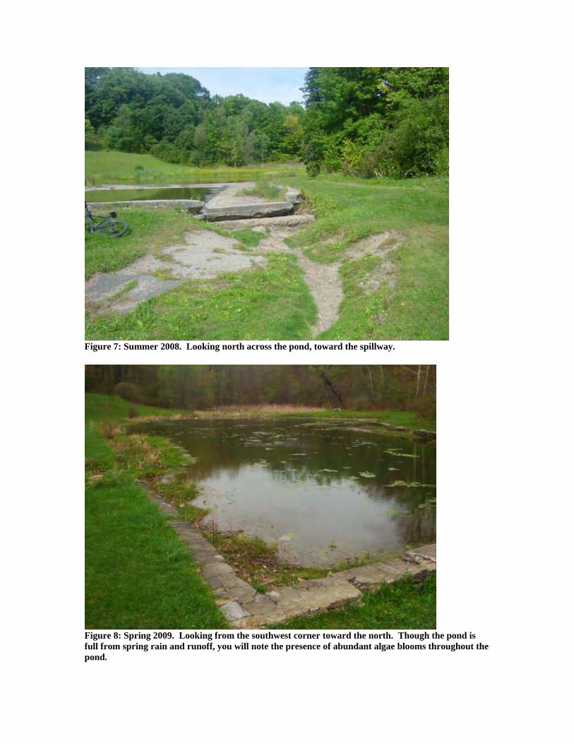
Figure 7: Summer 2008. Looking north across the pond, toward the spillway.
Figure 8: Spring 2009. Looking from the southwest corner toward the north. Though the pond isfull from spring rain and runoff, you will note the presence of abundant algae blooms throughout the pond.
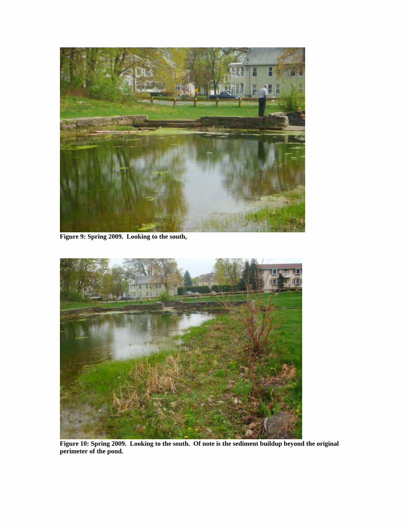
Figure 9: Spring 2009. Looking to the south,
Figure 10: Spring 2009. Looking to the south. Of note is the sediment buildup beyond the originalperimeter of the pond.
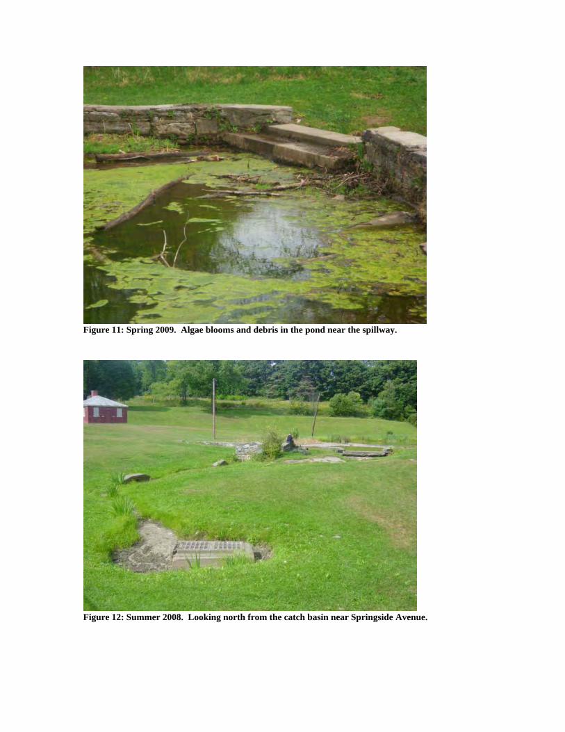
Figure 11: Spring 2009. Algae blooms and debris in the pond near the spillway.
Figure 12: Summer 2008. Looking north from the catch basin near Springside Avenue.


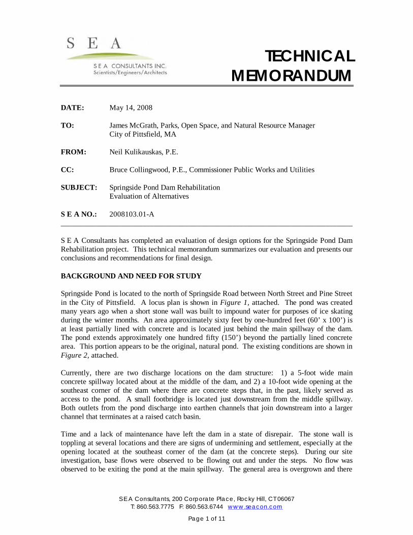
TECHNICAL
TECHNICALMEMORANDUM
S E A Consultants, 200 Corporate Place, Rocky Hill, CT 06067T: 860.563.7775 F: 860.563.6744 www.seacon.com
Page 1 of 11
DATE: May 14, 2008
TO: James McGrath, Parks, Open Space, and Natural Resource ManagerCity of Pittsfield, MA
FROM: Neil Kulikauskas, P.E.
CC: Bruce Collingwood, P.E., Commissioner Public Works and Utilities
SUBJECT: Springside Pond Dam RehabilitationEvaluation of Alternatives
S E A NO.: 2008103.01-A___________________________________________________________________________
S E A Consultants has completed an evaluation of design options for the Springside Pond DamRehabilitation project. This technical memorandum summarizes our evaluation and presents ourconclusions and recommendations for final design.
BACKGROUND AND NEED FOR STUDY
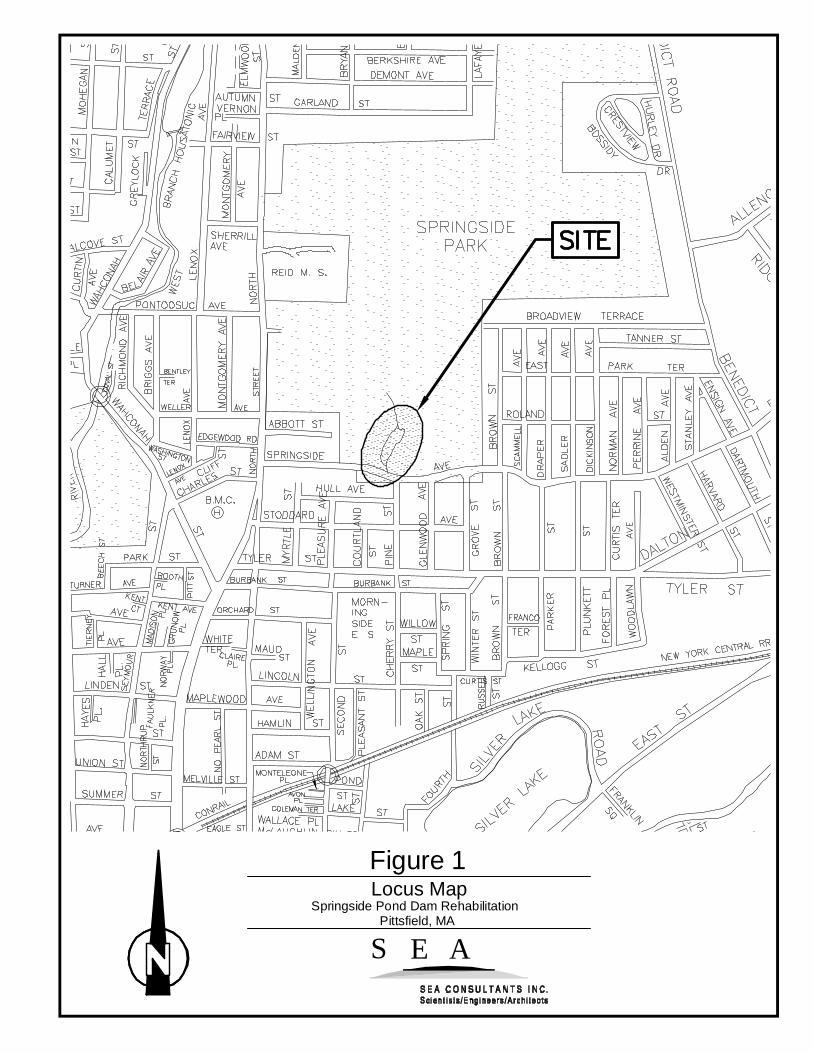
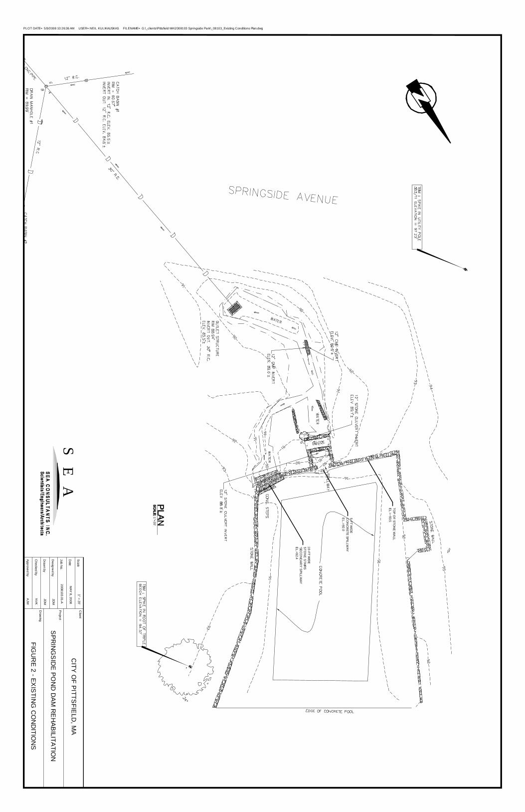
Springside Pond is located to the north of Springside Road between North Street and Pine Streetin the City of Pittsfield. A locus plan is shown in Figure 1, attached. The pond was createdmany years ago when a short stone wall was built to impound water for purposes of ice skatingduring the winter months. An area approximately sixty feet by one-hundred feet (60’ x 100’) isat least partially lined with concrete and is located just behind the main spillway of the dam.The pond extends approximately one hundred fifty (150’) beyond the partially lined concretearea. This portion appears to be the original, natural pond. The existing conditions are shown inFigure 2, attached.
Currently, there are two discharge locations on the dam structure: 1) a 5-foot wide mainconcrete spillway located about at the middle of the dam, and 2) a 10-foot wide opening at thesoutheast corner of the dam where there are concrete steps that, in the past, likely served asaccess to the pond. A small footbridge is located just downstream from the middle spillway.Both outlets from the pond discharge into earthen channels that join downstream into a largerchannel that terminates at a raised catch basin.
Time and a lack of maintenance have left the dam in a state of disrepair. The stone wall istoppling at several locations and there are signs of undermining and settlement, especially at theopening located at the southeast corner of the dam (at the concrete steps). During our siteinvestigation, base flows were observed to be flowing out and under the steps. No flow wasobserved to be exiting the pond at the main spillway. The general area is overgrown and there
TECHNICAL
TECHNICALMEMORANDUM
S E A Consultants, 200 Corporate Place, Rocky Hill, CT 06067T: 860.563.7775 F: 860.563.6744 www.seacon.com
Page 2 of 11
are several large pieces of stone wall and/or concrete lying within the main discharge channel.These are likely pieces of the stone wall that have broken off over time during high flow events.
HYDROLOGY
The watershed contributing to the pond is approximately 206 acres and consists mostly ofsloping wooded terrain with some open grassy and/or brushy areas. Minimal development existswithin the watershed. Existing flows into the pond were estimated using HydroCAD computersoftware using the National Resource Conservation Services TR-20 and TR-55 hydrologicanalysis procedures. The watershed boundary and the time of concentration were delineatedusing topographic information obtained from the City of Pittsfield’s GIS data and USGStopographic mapping. Land cover and land uses were determined from aerial mapping andhydrologic soil groups were based on mapping available from the State of Massachusetts GISwebsite (MassGIS). A watershed map is included as Figure 6, attached.
Based on the mapping data, the calculated runoff from the watershed was routed through thepond and into the downstream catch basin. The existing dam outlet geometry was based on sitesurvey performed by Hill Engineers on January 10, 2008. The existing storage definition of thepond was based on contours from GIS and is consistent with contours shown on USGS mapping.Storage at the catch basin downstream from the pond and the depth at which Springside Road isovertopping were partially based on the Hill survey and limited field reconnaissance by S E Astaff on April 3, 2008.
Consistent with Appendix B of the TR-55 analysis manual, 24-hour rainfall amounts for eachdesign storm were taken from the National Weather Service’s Technical Paper 40 (TP-40). Thecalculated peak flows are summarized in the following table.
Table 1: Peak Flows
Storm 24-hrRainfall (in.) Peak Flow (cfs)
2-yr 2.9 7.810-yr 4.4 54.025-yr 5.1 86.650-yr 5.9 129.6
100-yr 6.4 156.7
TECHNICAL
TECHNICALMEMORANDUM
S E A Consultants, 200 Corporate Place, Rocky Hill, CT 06067T: 860.563.7775 F: 860.563.6744 www.seacon.com
Page 3 of 11
EXISTING DAM HYDRAULICS
A starting water surface elevation in the pond of 91.5’ was assumed for the existing condition.This is consistent with the current level at the time of the survey and is appropriately 6 inchesbelow the spillway.
The height of the water in the pond and the amount of flow that is released from each outlet(main and secondary spillways) and over the top of the dam (stone wall) if applicable wasdetermined by routing the peak flows through the dam. The existing hydraulic results aresummarized in the following table.
Table 2: Existing Water Surface Elevations
Storm Peak Flow (cfs) Water SurfaceEl. (ft.)
2-yr 7.8 92.610-yr 54.0 93.325-yr 86.6 93.6*50-yr 129.6 93.9*
100-yr 156.7 94.0**overtops the stone wall dam
The analysis shows that for the 2-year storm, flow would typically be routed through the mainspillway (el. 92.0) and through the secondary spillway (stairs at el. 92.4). The stone wall dam isovertopped for the 25-year storm and greater.
The performance of the downstream inlet and culvert crossing Springside Road was alsoevaluated. The analysis showed that the road could be overtopped for the 25-year storm andgreater. Based on conversations with the City, though, the road has rarely been overtopped, andmore likely the storm flows are either conveyed in the gutter line or otherwise conveyed from thesite without actually flooding the road. For the purposes of modeling, though it was necessary toestablish the current performance to ensure that the design options did not worsen the existingcondition.

TECHNICAL
TECHNICALMEMORANDUM
S E A Consultants, 200 Corporate Place, Rocky Hill, CT 06067T: 860.563.7775 F: 860.563.6744 www.seacon.com
Page 4 of 11
DESIGN CRITERIA
The City has indicate that the ultimate goal is to repair the dam and restore the natural conditionof the overall pond while, if possible, retaining the original use as an area for ice skating. Toachieve a more natural appearance and to blend in with the existing terrain it was assumed thatthe following improvements would be consistent for all options:
� The stone wall dam would be removed and replaced with an earthen berm (heightvaries);
� The main concrete spillway would be removed and replaced with a main outlet structurein approximately the same location;
� The stone steps would be removed and replaced with a secondary spillway in theapproximate same location;
� The existing foot-bridge would be removed and replaced with a new structure;� The concrete lining would be removed and the bottom of the pond restored back to a
natural condition;� The channel between the spillway and the culvert inlet would be stabilized with riprap
(or equivalent lining) to minimize erosion; and� The inlet to the culvert crossing Springside Road would be lowered slightly to improve
hydraulics.
No improvement to the culvert crossing Springside Road would be required, and no work wouldbe required upstream of the concrete lined area to be removed
Thus, each design option only considered the type of outlets, the height of the new dam and theconfiguration of the earth impoundment to accommodate the outlet types. Each optionincorporates a main spillway set at a lower elevation to convey normal flow and a secondaryspillway sized to convey peak flows from storm events. Three design options were analyzed:
� Option #1: Pre-Cast U-Channel Outlet� Option #2: Trapezoidal Weir Outlet� Option #3: Multiple Box Culvert Outlet
There is no proposed change in the size of the pond; therefore any proposed increase in watersurface elevation would result in an increase in the discharge from the pond. This couldpotentially create downstream problems and should be avoided. Thus, each option was sizedsuch that the hydraulic performance (water surface elevation) was similar to or a slightimprovement compared to the existing condition.
TECHNICAL
TECHNICALMEMORANDUM
S E A Consultants, 200 Corporate Place, Rocky Hill, CT 06067T: 860.563.7775 F: 860.563.6744 www.seacon.com
Page 5 of 11
Additionally, the following design criteria were chosen for the new dam:
� The main spillway will be sized to best match the normal flows including the 2-yearstorm event.
� The secondary spillway will be sized to accommodate up to the 100-yr storm event, and� No overtopping for up through the 100-year storm event.
The following sections evaluate each design option compared to the existing pond. Apreliminary capital cost estimate for each is also given. The capital cost would includeconstruction costs as well as engineering costs for design and permitting.
OPTION #1: PRE-CAST U-CHANNEL OUTLET
Description
This option proposes:
� An 8-foot wide pre-cast concrete U-channel outlet set at El. 92.0,� A 10-foot wide secondary spillway set at El. 92.5, and� An earthen dam constructed to El. 94.5.
This option is shown in Figure 3, attached.
Hydraulic Performance
The following table shows a comparison of peak water surface elevations for this optioncompared to the existing condition.
Table 3: Proposed Water Surface Elevations – Option #1
Storm Existing WaterSurface El. (ft.)
ProposedWater Surface
El. (ft.)2-yr 92.6 92.5
10-yr 93.3 93.325-yr 93.6* 93.750-yr 93.9* 94.0
100-yr 94.0* 94.3*overtops the stone wall dam

TECHNICAL
TECHNICALMEMORANDUM
S E A Consultants, 200 Corporate Place, Rocky Hill, CT 06067T: 860.563.7775 F: 860.563.6744 www.seacon.com
Page 6 of 11
For this option, the water surface elevations are similar for up through the 25-year event. Thisoption would include raising the height of the berm to 94.5, which would prevent overtopping asseen for the existing condition.
Preliminary Cost
The following table shows a preliminary estimate of probable capital cost for this option.
Table 4: Estimated Capital Cost –Option #1
Item Quantity Unit Unit Cost Item TotalMobilization/Demobilization 1 LS $10,000 $10,000Clear and Grub 1 LS $5,000 $5,000Remove Existing Dam, Concrete Lining, Foot Bridge 1 LS $50,000 $50,000Earthwork 1,200 CY $75 $90,000Pre-Cast U-Channel 1 EA $15,000 $15,000Clean, Regrade, Stabilize Channels 150 LF $100 $15,000Replace Culvert Inlet 1 EA $3,000 $3,000Restoration 15,000 SF $1 $15,000Foot Bridge 1 LS $10,000 $10,000Flow Diversion 1 LS $10,000 $10,000Erosion Control 1 LS $10,000 $10,000
Subtotal $233,000Contingency (20%) $46,600Construction Total $279,600Engineering (15%) $41,940Total (Rounded) $330,000
Advantages/Disadvantages
The advantages include:
� Good hydraulics,� Stable main spillway, and� Easy to maintain.
The disadvantages include:
� Structural (un-natural) spillway and� Requires larger earthen dam to El. 94.5.
TECHNICAL
TECHNICALMEMORANDUM
S E A Consultants, 200 Corporate Place, Rocky Hill, CT 06067T: 860.563.7775 F: 860.563.6744 www.seacon.com
Page 7 of 11
OPTION #2: TRAPEZOIDAL WEIR OUTLET
Description
This option proposes:
� An 8-foot wide trapezoidal weir set at El. 92.0,� A 12-foot wide secondary spillway set at El. 92.5, and� An earthen dam constructed to El. 94.0.
This option is shown in Figure 4, attached.
Hydraulic Performance
The following table shows a comparison of peak water surface elevations for this optioncompared to the existing condition.
Table 5: Proposed Water Surface Elevations – Option #2
Storm Existing WaterSurface El. (ft.)
ProposedWater Surface
El. (ft.)2-yr 92.6 92.5
10-yr 93.3 93.225-yr 93.6* 93.550-yr 93.9* 93.8
100-yr 94.0* 94.0*overtops the stone wall dam
For this option, the water surface elevations are similar to the existing for all storm events. Thisoption would only require the height of the berm to 94.0, (six in. lower than Option #1), andwould still prevent overtopping for all events up through the 100-year.

TECHNICAL
TECHNICALMEMORANDUM
S E A Consultants, 200 Corporate Place, Rocky Hill, CT 06067T: 860.563.7775 F: 860.563.6744 www.seacon.com
Page 8 of 11
Preliminary Cost
The following table shows a preliminary estimate of probable construction cost for this option.
Table 6: Estimated Capital Cost –Option #2
Item Quantity Unit Unit Cost Item TotalMobilization/Demobilization 1 LS $10,000 $10,000Clear and Grub 1 LS $5,000 $5,000Remove Existing Dam, Concrete Lining, Foot Bridge 1 LS $50,000 $50,000Earthwork 1,000 CY $75 $75,000Construct weir 1 EA $5,000 $5,000Clean, Regrade Stabilize Channels 150 LF $100 $15,000Replace Culvert Inlet 1 EA $3,000 $3,000Restoration 15,000 SF $1 $15,000Foot Bridge 1 LS $10,000 $10,000Flow Diversion 1 LS $10,000 $10,000Erosion Control 1 LS $10,000 $10,000
Construction Subtotal $208,000Contingency (20%) $41,600Construction Total $249,600Engineering (15%) $37,440
Construction Total (Rounded) $290,000
Advantages/Disadvantages
The advantages include:
� Good hydraulics,� Natural-looking spillway,� Easy to maintain, and� Slightly lower cost than Option #1.
The disadvantages include:
� Stable, but more prone to erosion compared to Option #1.
TECHNICAL
TECHNICALMEMORANDUM
S E A Consultants, 200 Corporate Place, Rocky Hill, CT 06067T: 860.563.7775 F: 860.563.6744 www.seacon.com
Page 9 of 11
OPTION #3: MULTIPLE BOX CULVERT OUTLET
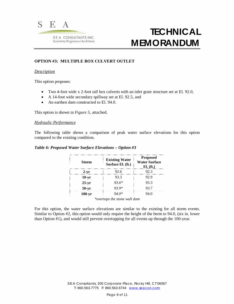
Description
This option proposes:
� Two 4-foot wide x 2-foot tall box culverts with an inlet grate structure set at El. 92.0,� A 14-foot wide secondary spillway set at El. 92.5, and� An earthen dam constructed to El. 94.0.
This option is shown in Figure 5, attached.
Hydraulic Performance
The following table shows a comparison of peak water surface elevations for this optioncompared to the existing condition.
Table 6: Proposed Water Surface Elevations – Option #3
Storm Existing WaterSurface El. (ft.)
ProposedWater Surface
El. (ft.)2-yr 92.6 92.3
10-yr 93.3 92.925-yr 93.6* 93.350-yr 93.9* 93.7
100-yr 94.0* 94.0*overtops the stone wall dam
For this option, the water surface elevations are similar to the existing for all storm events.Similar to Option #2, this option would only require the height of the berm to 94.0, (six in. lowerthan Option #1), and would still prevent overtopping for all events up through the 100-year.

TECHNICAL
TECHNICALMEMORANDUM
S E A Consultants, 200 Corporate Place, Rocky Hill, CT 06067T: 860.563.7775 F: 860.563.6744 www.seacon.com
Page 10 of 11
Preliminary Cost
The following table shows a preliminary estimate of probable construction cost for this option.
Table 6: Estimated Capital Cost –Option #3
Item Quantity Unit Unit Cost Item TotalMobilization/Demobilization 1 LS $10,000 $10,000Clear and Grub 1 LS $5,000 $5,000Remove Existing Dam, Concrete Lining, Foot Bridge 1 LS $50,000 $50,000Earthwork 1,000 CY $75 $75,0004x2 Box Culverts, Inlet Structure 1 EA $25,000 $25,000Clean, Regrade Stabilize Channels 150 LF $100 $15,000Replace Culvert Inlet 1 EA $3,000 $3,000Restoration 15,000 SF $1 $15,000Foot Bridge 1 LS $10,000 $10,000Flow Diversion 1 LS $10,000 $10,000Erosion Control 1 LS $10,000 $10,000
Construction Subtotal $228,000Contingency (20%) $45,600Construction Total $273,600Engineering (15%) $41,040
Construction Total (Rounded) $320,000
Advantages/Disadvantages
The advantages include:
� Good hydraulics and� Stable main spillway.
The disadvantages include:
� Largest capital cost,� Difficult to maintain as grate would require frequent cleaning, and� Different than existing (no real ‘spillway’).

TECHNICAL
TECHNICALMEMORANDUM
S E A Consultants, 200 Corporate Place, Rocky Hill, CT 06067T: 860.563.7775 F: 860.563.6744 www.seacon.com
Page 11 of 11
CONCLUSIONS AND RECOMMENDATIONS
The preferred design option should blend in well with the natural surroundings of the pond. Itshould be of an appropriate scale so that no one design feature stands out over the other oroverpowers the existing site features to remain (e.g. existing trees, wetlands, etc.). The hydraulicperformance of the preferred option should also match or improve upon the performance of theexisting dam and spillways.
Based on the analysis, we recommend Option #2, installation of a broad-crested concrete androck weir outlet, for or an estimated cost of $290k. This option is best suited to blend with thenatural surroundings, is the least expensive, and performs well hydraulically with no significantdifferences compared to other options.
Upon your review and approval of our recommendation, the next steps would be to prepare finaldesign plans and technical specifications and acquire the necessary local, state and federalpermits. The permits required for any of the options may include:
� Local Order of Conditions� US Army Corps Programmatic General Permit (PGP) Category 2� 401 Water Quality Certification (WQC)� Environmental Notification Form (ENF)
It is likely that the removal of the concrete from the pond bottom would exceed the 5000-squarefoot of resource area threshold, which would trigger the WQC, PGP and ENF. Also please notethat as part of our effort, we completed sufficient topographic survey and completed thegeotechnical investigations necessary for the final design effort.
ATTACHMENTS
� Figure 1 - Site Locus Map� Figure 2 - Existing Conditions Plan� Figure 3 - Option #1� Figure 4 - Option #2� Figure 5 - Option #3� Figure 6 – Watershed Map� Hydrology & Hydraulic Calculations
S E A
Figure 1Locus Map
Springside Pond Dam RehabilitationPittsfield, MA
5-FT WID
EC
ON
CR
ETE SPILLW
AYE
L..=92.0
10-FT WID
ES
TON
E S
TAIRS
'SEC
ON
DAR
Y' SPILLW
AYE
L.=92.4
TOP
OF STO
NE
WA
LLE
L.=~93.5
PLOT DATE= 5/9/2008 10:26:36 AM USER= NEIL KULIKAUSKAS FILENAME= G:\_clients\Pittsfield MA\2008103 Springside Park\_08103_Existing Conditions Plan.dwg
Project
Client
Draw
ing
CITY O
F PITTS
FIELD
, MA
SPR
ING
SID
E PON
D D
AM R
EH
ABILITATIO
N
FIGU
RE 2 - EX
ISTIN
G C
ON
DITIO
NS
Draw
n by
Designed by
Scale
Date
Job No.
Approved by
Checked by
1" = 20'
2008103.01-A
JDM
JDM
NVK
AJW
MAY 8, 2008
SE
A
1"=20'
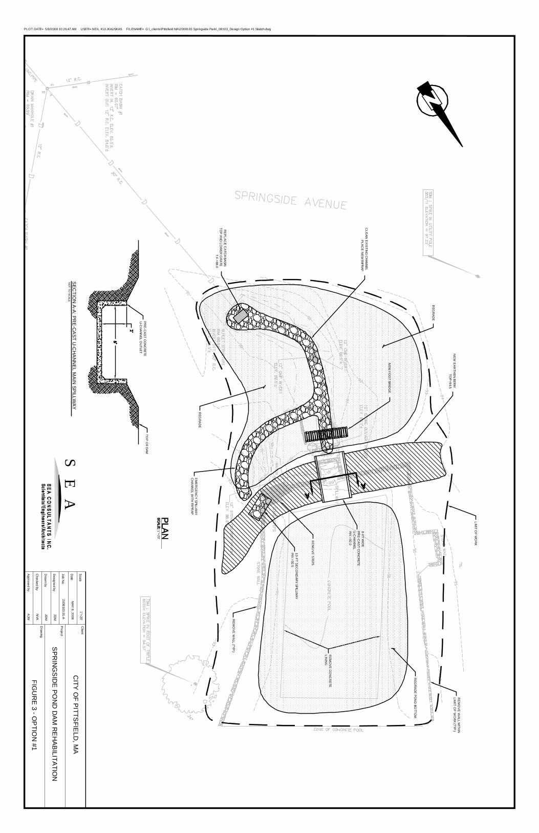
RE
MO
VE
WA
LL WITH
INLIM
IT OF W
OR
K (TYP.)
RE
MO
VE
WA
LL (TYP.)
REM
OV
E CO
NC
RE
TELIN
ING
RE
MO
VE STEPS
LIMIT O
F WO
RK
RE
PLA
CE
CA
TCH
BASINTO
P A
ND
LOW
ER G
RA
TET.F.=88.0
REG
RA
DE
REG
RA
DE
REG
RA
DE P
ON
D BO
TTOM
8-FT WID
EP
RE
-CA
ST C
ON
CR
ETEU
-CH
AN
NEL
INV
.=92.0
10-FT SE
CO
ND
ARY SPILLW
AYIN
V.=92.5
EM
ER
GE
NC
Y SPILLW
AYC
HA
NN
EL WITH
RIPR
AP
CLE
AN
EX
ISTIN
G C
HAN
NEL
PLA
CE
NE
W R
IPRAP
NE
W E
AR
THEN
BERM
TOP
=94.5
NEW
FOO
T BRID
GE
SEC
TION
A-A
: PRE-C
AST U
-CH
AN
NEL M
AIN SPILLW
AYN
OT TO
SCALE
TOP
OF
DAM
PR
E-C
AS
T CO
NC
RETE
U-C
HA
NN
EL OU
TLET
1"=20'
PLOT DATE= 5/9/2008 10:26:47 AM USER= NEIL KULIKAUSKAS FILENAME= G:\_clients\Pittsfield MA\2008103 Springside Park\_08103_Design Option #1 Sketch.dwg
Project
Client
Draw
ing
CITY O
F PITTS
FIELD
, MA
SPR
ING
SID
E PON
D D
AM R
EH
ABILITATIO
N
FIGU
RE 3 - O
PTIO
N #1
Draw
n by
Designed by
Scale
Date
Job No.
Approved by
Checked by
1"=20'
2008103.01-A
JDM
JDM
NVK
AJW
MAY 8, 2008
SE
A
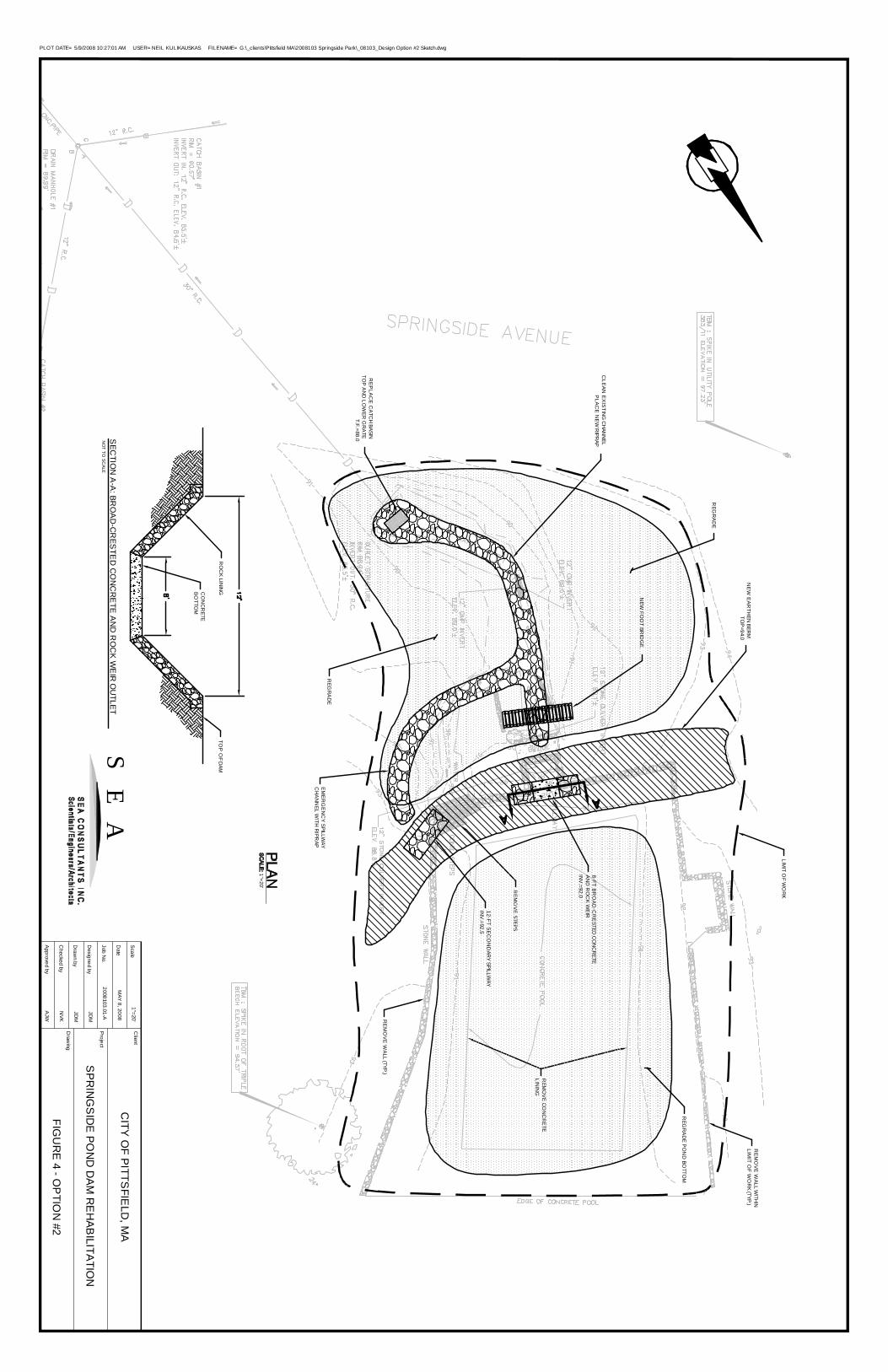
RE
MO
VE
WA
LL WITH
INLIM
IT OF W
OR
K (TYP.)
RE
MO
VE
WA
LL (TYP.)
REM
OV
E CO
NC
RE
TELIN
ING
RE
MO
VE STEPS
LIMIT O
F WO
RK
RE
PLA
CE
CA
TCH
BASINTO
P A
ND
LOW
ER G
RA
TET.F.=88.0
REG
RA
DE
REG
RA
DE
REG
RA
DE P
ON
D BO
TTOM
8-FT BR
OA
D-C
RE
STED C
ON
CR
ETEA
ND
RO
CK
WE
IRIN
V.=92.0
12-FT SE
CO
ND
ARY SPILLW
AYIN
V.=92.5
EM
ER
GE
NC
Y SPILLW
AYC
HA
NN
EL WITH
RIPR
AP
CLE
AN
EX
ISTIN
G C
HAN
NEL
PLA
CE
NE
W R
IPRAP
NE
W E
AR
THEN
BERM
TOP
=94.0
NEW
FOO
T BRID
GE
SEC
TION
A-A
: BRO
AD
-CR
ESTE
D C
ON
CR
ETE A
ND
RO
CK W
EIR
OU
TLETN
OT TO
SCALE
TOP
OF
DAM
CO
NC
RETE
BO
TTOM
RO
CK LIN
ING
1"=20'
PLOT DATE= 5/9/2008 10:27:01 AM USER= NEIL KULIKAUSKAS FILENAME= G:\_clients\Pittsfield MA\2008103 Springside Park\_08103_Design Option #2 Sketch.dwg
Project
Client
Draw
ing
CITY O
F PITTS
FIELD
, MA
SPR
ING
SID
E PON
D D
AM R
EH
ABILITATIO
N
FIGU
RE 4 - O
PTIO
N #2
Draw
n by
Designed by
Scale
Date
Job No.
Approved by
Checked by
1"=20'
2008103.01-A
JDM
JDM
NVK
AJW
MAY 8, 2008
SE
A
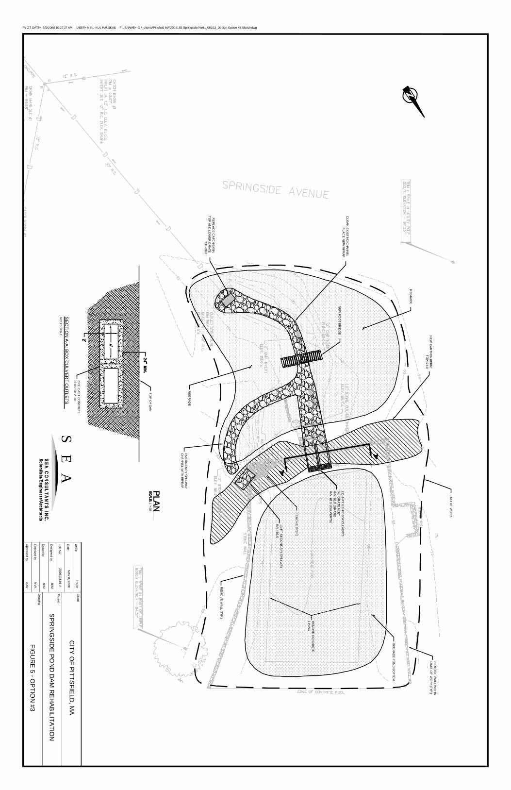
RE
MO
VE
WA
LL WITH
INLIM
IT OF W
OR
K (TYP.)
RE
MO
VE
WA
LL (TYP.)
REM
OV
E CO
NC
RE
TELIN
ING
RE
MO
VE STEPS
LIMIT O
F WO
RK
RE
PLA
CE
CA
TCH
BASINTO
P A
ND
LOW
ER G
RA
TET.F.=88.0
REG
RA
DE
REG
RA
DE
REG
RA
DE P
ON
D BO
TTOM
(2) 4-FT X 2-FT BOX C
ULVER
TSW
/ GR
ATE IN
LETIN
V. 92.0 (G
RATE)
INV
. 89.5 (CU
LVER
TS)
14-FT SE
CO
ND
ARY SPILLW
AYIN
V.=92.5
EM
ER
GE
NC
Y SPILLW
AYC
HA
NN
EL WITH
RIPR
AP
CLE
AN
EX
ISTIN
G C
HAN
NEL
PLA
CE
NE
W R
IPRAP
NE
W E
AR
THEN
BERM
TOP
=94.0
NEW
FOO
T BRID
GE
SEC
TION
A-A
: BOX C
ULV
ERT O
UTLETS
NO
T TO SC
ALE
TOP
OF
DAM
PR
E-C
AS
T CO
NC
RETE
BO
X C
ULVE
RT
1"=20'
PLOT DATE= 5/9/2008 10:27:27 AM USER= NEIL KULIKAUSKAS FILENAME= G:\_clients\Pittsfield MA\2008103 Springside Park\_08103_Design Option #3 Sketch.dwg
Project
Client
Draw
ing
CITY O
F PITTS
FIELD
, MA
SPR
ING
SID
E PON
D D
AM R
EH
ABILITATIO
N
FIGU
RE 5 - O
PTIO
N #3
Draw
n by
Designed by
Scale
Date
Job No.
Approved by
Checked by
1"=20'
2008103.01-A
JDM
JDM
NVK
AJW
MAY 8, 2008
SE
A
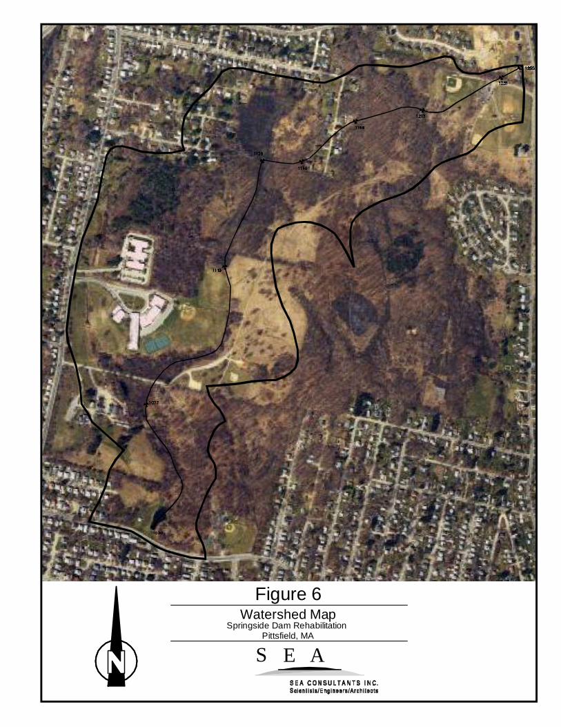
S E A
Figure 6Watershed Map
Springside Dam RehabilitationPittsfield, MA

Type III 24-hr 2-year Rainfall=2.90"Springside Pond Printed 5/9/2008Prepared by {enter your company name here}
Page 1HydroCAD® 8.50 s/n 000865 © 2007 HydroCAD Software Solutions LLC
Time span=0.00-60.00 hrs, dt=0.01 hrs, 6001 points x 3Runoff by SCS TR-20 method, UH=SCS
Reach routing by Dyn-Stor-Ind method - Pond routing by Dyn-Stor-Ind method
Runoff Area=206.420 ac 8.11% Impervious Runoff Depth=0.27"Subcatchment S1: Pond Watershed Flow Length=6,927' Tc=78.8 min CN=59 Runoff=11.93 cfs 4.638 af
Peak Elev=92.55' Storage=63,583 cf Inflow=11.93 cfs 4.638 afPond P1: Pond (Existing) Primary=6.50 cfs 3.849 af Secondary=1.84 cfs 0.319 af Outflow=8.35 cfs 4.168 af
Peak Elev=89.05' Storage=122 cf Inflow=8.35 cfs 4.168 afPond P2: 30" Culvert w/ CB (Existing) Primary=8.35 cfs 4.168 af Secondary=0.00 cfs 0.000 af Outflow=8.35 cfs 4.168 af
Total Runoff Area = 206.420 ac Runoff Volume = 4.638 af Average Runoff Depth = 0.27"91.89% Pervious = 189.680 ac 8.11% Impervious = 16.740 ac

Type III 24-hr 10-year Rainfall=4.40"Springside Pond Printed 5/9/2008Prepared by {enter your company name here}
Page 2HydroCAD® 8.50 s/n 000865 © 2007 HydroCAD Software Solutions LLC
Time span=0.00-60.00 hrs, dt=0.01 hrs, 6001 points x 3Runoff by SCS TR-20 method, UH=SCS
Reach routing by Dyn-Stor-Ind method - Pond routing by Dyn-Stor-Ind method
Runoff Area=206.420 ac 8.11% Impervious Runoff Depth=0.91"Subcatchment S1: Pond Watershed Flow Length=6,927' Tc=78.8 min CN=59 Runoff=59.80 cfs 15.650 af
Peak Elev=93.33' Storage=104,448 cf Inflow=59.80 cfs 15.650 afPond P1: Pond (Existing) Primary=24.51 cfs 9.536 af Secondary=30.10 cfs 5.645 af Outflow=54.61 cfs 15.181 af
Peak Elev=91.88' Storage=10,378 cf Inflow=54.61 cfs 15.181 afPond P2: 30" Culvert w/ CB (Existing) Primary=51.77 cfs 15.181 af Secondary=0.00 cfs 0.000 af Outflow=51.77 cfs 15.181 af
Total Runoff Area = 206.420 ac Runoff Volume = 15.650 af Average Runoff Depth = 0.91"91.89% Pervious = 189.680 ac 8.11% Impervious = 16.740 ac

Type III 24-hr 25-year Rainfall=5.10"Springside Pond Printed 5/9/2008Prepared by {enter your company name here}
Page 3HydroCAD® 8.50 s/n 000865 © 2007 HydroCAD Software Solutions LLC
Time span=0.00-60.00 hrs, dt=0.01 hrs, 6001 points x 3Runoff by SCS TR-20 method, UH=SCS
Reach routing by Dyn-Stor-Ind method - Pond routing by Dyn-Stor-Ind method
Runoff Area=206.420 ac 8.11% Impervious Runoff Depth=1.29"Subcatchment S1: Pond Watershed Flow Length=6,927' Tc=78.8 min CN=59 Runoff=90.63 cfs 22.214 af
Peak Elev=93.63' Storage=121,664 cf Inflow=90.63 cfs 22.214 afPond P1: Pond (Existing) Primary=29.54 cfs 11.843 af Secondary=58.12 cfs 9.901 af Outflow=86.91 cfs 21.745 af
Peak Elev=92.73' Storage=19,919 cf Inflow=86.91 cfs 21.745 afPond P2: 30" Culvert w/ CB (Existing) Primary=57.13 cfs 20.316 af Secondary=29.71 cfs 1.429 af Outflow=86.84 cfs 21.745 af
Total Runoff Area = 206.420 ac Runoff Volume = 22.214 af Average Runoff Depth = 1.29"91.89% Pervious = 189.680 ac 8.11% Impervious = 16.740 ac

Type III 24-hr 50-year Rainfall=5.90"Springside Pond Printed 5/9/2008Prepared by {enter your company name here}
Page 4HydroCAD® 8.50 s/n 000865 © 2007 HydroCAD Software Solutions LLC
Time span=0.00-60.00 hrs, dt=0.01 hrs, 6001 points x 3Runoff by SCS TR-20 method, UH=SCS
Reach routing by Dyn-Stor-Ind method - Pond routing by Dyn-Stor-Ind method
Runoff Area=206.420 ac 8.11% Impervious Runoff Depth=1.78"Subcatchment S1: Pond Watershed Flow Length=6,927' Tc=78.8 min CN=59 Runoff=130.75 cfs 30.535 af
Peak Elev=93.88' Storage=136,020 cf Inflow=130.75 cfs 30.535 afPond P1: Pond (Existing) Primary=31.94 cfs 14.114 af Secondary=96.70 cfs 15.952 af Outflow=128.64 cfs 30.066 af
Peak Elev=92.91' Storage=22,395 cf Inflow=128.64 cfs 30.066 afPond P2: 30" Culvert w/ CB (Existing) Primary=58.04 cfs 24.865 af Secondary=70.54 cfs 5.201 af Outflow=128.58 cfs 30.066 af
Total Runoff Area = 206.420 ac Runoff Volume = 30.535 af Average Runoff Depth = 1.78"91.89% Pervious = 189.680 ac 8.11% Impervious = 16.740 ac

Type III 24-hr 100-year Rainfall=6.40"Springside Pond Printed 5/9/2008Prepared by {enter your company name here}
Page 5HydroCAD® 8.50 s/n 000865 © 2007 HydroCAD Software Solutions LLC
Time span=0.00-60.00 hrs, dt=0.01 hrs, 6001 points x 3Runoff by SCS TR-20 method, UH=SCS
Reach routing by Dyn-Stor-Ind method - Pond routing by Dyn-Stor-Ind method
Runoff Area=206.420 ac 8.11% Impervious Runoff Depth=2.10"Subcatchment S1: Pond Watershed Flow Length=6,927' Tc=78.8 min CN=59 Runoff=157.68 cfs 36.105 af
Peak Elev=94.01' Storage=144,187 cf Inflow=157.68 cfs 36.105 afPond P1: Pond (Existing) Primary=33.40 cfs 15.406 af Secondary=122.37 cfs 20.229 af Outflow=155.77 cfs 35.636 af
Peak Elev=93.01' Storage=23,819 cf Inflow=155.77 cfs 35.636 afPond P2: 30" Culvert w/ CB (Existing) Primary=58.54 cfs 27.414 af Secondary=97.18 cfs 8.222 af Outflow=155.72 cfs 35.636 af
Total Runoff Area = 206.420 ac Runoff Volume = 36.105 af Average Runoff Depth = 2.10"91.89% Pervious = 189.680 ac 8.11% Impervious = 16.740 ac

Type III 24-hr 2-year Rainfall=2.90"Springside Pond Printed 5/9/2008Prepared by {enter your company name here}
Page 1HydroCAD® 8.50 s/n 000865 © 2007 HydroCAD Software Solutions LLC
Time span=0.00-60.00 hrs, dt=0.01 hrs, 6001 points x 3Runoff by SCS TR-20 method, UH=SCS
Reach routing by Dyn-Stor-Ind method - Pond routing by Dyn-Stor-Ind method
Runoff Area=206.420 ac 8.11% Impervious Runoff Depth=0.27"Subcatchment S2: Pond Watershed Flow Length=6,927' Tc=78.8 min CN=59 Runoff=11.93 cfs 4.638 af
Peak Elev=92.52' Storage=92,993 cf Inflow=11.93 cfs 4.638 afPond P3: Pond (Option #1) Primary=8.11 cfs 4.164 af Secondary=0.10 cfs 0.005 af Outflow=8.21 cfs 4.169 af
Peak Elev=88.14' Storage=5 cf Inflow=8.21 cfs 4.169 afPond P4: 30" Culvert w/ CB (Option #1) Primary=8.21 cfs 4.169 af Secondary=0.00 cfs 0.000 af Outflow=8.21 cfs 4.169 af
Total Runoff Area = 206.420 ac Runoff Volume = 4.638 af Average Runoff Depth = 0.27"91.89% Pervious = 189.680 ac 8.11% Impervious = 16.740 ac

Type III 24-hr 10-year Rainfall=4.40"Springside Pond Printed 5/9/2008Prepared by {enter your company name here}
Page 2HydroCAD® 8.50 s/n 000865 © 2007 HydroCAD Software Solutions LLC
Time span=0.00-60.00 hrs, dt=0.01 hrs, 6001 points x 3Runoff by SCS TR-20 method, UH=SCS
Reach routing by Dyn-Stor-Ind method - Pond routing by Dyn-Stor-Ind method
Runoff Area=206.420 ac 8.11% Impervious Runoff Depth=0.91"Subcatchment S2: Pond Watershed Flow Length=6,927' Tc=78.8 min CN=59 Runoff=59.80 cfs 15.650 af
Peak Elev=93.29' Storage=133,020 cf Inflow=59.80 cfs 15.650 afPond P3: Pond (Option #1) Primary=30.53 cfs 11.482 af Secondary=24.50 cfs 3.699 af Outflow=54.53 cfs 15.182 af
Peak Elev=92.57' Storage=17,778 cf Inflow=54.53 cfs 15.182 afPond P4: 30" Culvert w/ CB (Option #1) Primary=46.30 cfs 15.096 af Secondary=4.51 cfs 0.086 af Outflow=50.81 cfs 15.182 af
Total Runoff Area = 206.420 ac Runoff Volume = 15.650 af Average Runoff Depth = 0.91"91.89% Pervious = 189.680 ac 8.11% Impervious = 16.740 ac

Type III 24-hr 25-year Rainfall=5.10"Springside Pond Printed 5/9/2008Prepared by {enter your company name here}
Page 3HydroCAD® 8.50 s/n 000865 © 2007 HydroCAD Software Solutions LLC
Time span=0.00-60.00 hrs, dt=0.01 hrs, 6001 points x 3Runoff by SCS TR-20 method, UH=SCS
Reach routing by Dyn-Stor-Ind method - Pond routing by Dyn-Stor-Ind method
Runoff Area=206.420 ac 8.11% Impervious Runoff Depth=1.29"Subcatchment S2: Pond Watershed Flow Length=6,927' Tc=78.8 min CN=59 Runoff=90.63 cfs 22.214 af
Peak Elev=93.68' Storage=155,066 cf Inflow=90.63 cfs 22.214 afPond P3: Pond (Option #1) Primary=39.69 cfs 14.764 af Secondary=44.97 cfs 6.981 af Outflow=84.65 cfs 21.745 af
Peak Elev=92.77' Storage=20,427 cf Inflow=84.65 cfs 21.745 afPond P4: 30" Culvert w/ CB (Option #1) Primary=47.31 cfs 19.305 af Secondary=37.29 cfs 2.440 af Outflow=84.61 cfs 21.745 af
Total Runoff Area = 206.420 ac Runoff Volume = 22.214 af Average Runoff Depth = 1.29"91.89% Pervious = 189.680 ac 8.11% Impervious = 16.740 ac

Type III 24-hr 50-year Rainfall=5.90"Springside Pond Printed 5/9/2008Prepared by {enter your company name here}
Page 4HydroCAD® 8.50 s/n 000865 © 2007 HydroCAD Software Solutions LLC
Time span=0.00-60.00 hrs, dt=0.01 hrs, 6001 points x 3Runoff by SCS TR-20 method, UH=SCS
Reach routing by Dyn-Stor-Ind method - Pond routing by Dyn-Stor-Ind method
Runoff Area=206.420 ac 8.11% Impervious Runoff Depth=1.78"Subcatchment S2: Pond Watershed Flow Length=6,927' Tc=78.8 min CN=59 Runoff=130.75 cfs 30.535 af
Peak Elev=94.07' Storage=178,433 cf Inflow=130.75 cfs 30.535 afPond P3: Pond (Option #1) Primary=54.49 cfs 18.574 af Secondary=70.31 cfs 11.492 af Outflow=124.79 cfs 30.066 af
Peak Elev=92.93' Storage=22,730 cf Inflow=124.79 cfs 30.066 afPond P4: 30" Culvert w/ CB (Option #1) Primary=48.12 cfs 23.296 af Secondary=76.63 cfs 6.770 af Outflow=124.75 cfs 30.066 af
Total Runoff Area = 206.420 ac Runoff Volume = 30.535 af Average Runoff Depth = 1.78"91.89% Pervious = 189.680 ac 8.11% Impervious = 16.740 ac

Type III 24-hr 100-year Rainfall=6.40"Springside Pond Printed 5/9/2008Prepared by {enter your company name here}
Page 5HydroCAD® 8.50 s/n 000865 © 2007 HydroCAD Software Solutions LLC
Time span=0.00-60.00 hrs, dt=0.01 hrs, 6001 points x 3Runoff by SCS TR-20 method, UH=SCS
Reach routing by Dyn-Stor-Ind method - Pond routing by Dyn-Stor-Ind method
Runoff Area=206.420 ac 8.11% Impervious Runoff Depth=2.10"Subcatchment S2: Pond Watershed Flow Length=6,927' Tc=78.8 min CN=59 Runoff=157.68 cfs 36.105 af
Peak Elev=94.30' Storage=192,812 cf Inflow=157.68 cfs 36.105 afPond P3: Pond (Option #1) Primary=64.04 cfs 20.970 af Secondary=87.54 cfs 14.667 af Outflow=151.58 cfs 35.636 af
Peak Elev=93.03' Storage=24,117 cf Inflow=151.58 cfs 35.636 afPond P4: 30" Culvert w/ CB (Option #1) Primary=48.57 cfs 25.537 af Secondary=102.96 cfs 10.100 af Outflow=151.54 cfs 35.636 af
Total Runoff Area = 206.420 ac Runoff Volume = 36.105 af Average Runoff Depth = 2.10"91.89% Pervious = 189.680 ac 8.11% Impervious = 16.740 ac

Type III 24-hr 2-year Rainfall=2.90"Springside Pond Printed 5/9/2008Prepared by {enter your company name here}
Page 1HydroCAD® 8.50 s/n 000865 © 2007 HydroCAD Software Solutions LLC
Time span=0.00-60.00 hrs, dt=0.01 hrs, 6001 points x 3Runoff by SCS TR-20 method, UH=SCS
Reach routing by Dyn-Stor-Ind method - Pond routing by Dyn-Stor-Ind method
Runoff Area=206.420 ac 8.11% Impervious Runoff Depth=0.27"Subcatchment S3: Pond Watershed Flow Length=6,927' Tc=78.8 min CN=59 Runoff=11.93 cfs 4.638 af
Peak Elev=92.46' Storage=90,130 cf Inflow=11.93 cfs 4.638 afPond P5: Pond (Option #2) Primary=8.58 cfs 4.169 af Secondary=0.00 cfs 0.000 af Outflow=8.58 cfs 4.169 af
Peak Elev=88.16' Storage=5 cf Inflow=8.58 cfs 4.169 afPond P6: 30" Culvert w/ CB (Option #2) Primary=8.58 cfs 4.169 af Secondary=0.00 cfs 0.000 af Outflow=8.58 cfs 4.169 af
Total Runoff Area = 206.420 ac Runoff Volume = 4.638 af Average Runoff Depth = 0.27"91.89% Pervious = 189.680 ac 8.11% Impervious = 16.740 ac

Type III 24-hr 10-year Rainfall=4.40"Springside Pond Printed 5/9/2008Prepared by {enter your company name here}
Page 2HydroCAD® 8.50 s/n 000865 © 2007 HydroCAD Software Solutions LLC
Time span=0.00-60.00 hrs, dt=0.01 hrs, 6001 points x 3Runoff by SCS TR-20 method, UH=SCS
Reach routing by Dyn-Stor-Ind method - Pond routing by Dyn-Stor-Ind method
Runoff Area=206.420 ac 8.11% Impervious Runoff Depth=0.91"Subcatchment S3: Pond Watershed Flow Length=6,927' Tc=78.8 min CN=59 Runoff=59.80 cfs 15.650 af
Peak Elev=93.15' Storage=125,187 cf Inflow=59.80 cfs 15.650 afPond P5: Pond (Option #2) Primary=35.15 cfs 12.327 af Secondary=21.33 cfs 2.855 af Outflow=55.91 cfs 15.182 af
Peak Elev=92.58' Storage=17,995 cf Inflow=55.91 cfs 15.182 afPond P6: 30" Culvert w/ CB (Option #2) Primary=46.38 cfs 15.035 af Secondary=6.40 cfs 0.147 af Outflow=52.78 cfs 15.182 af
Total Runoff Area = 206.420 ac Runoff Volume = 15.650 af Average Runoff Depth = 0.91"91.89% Pervious = 189.680 ac 8.11% Impervious = 16.740 ac
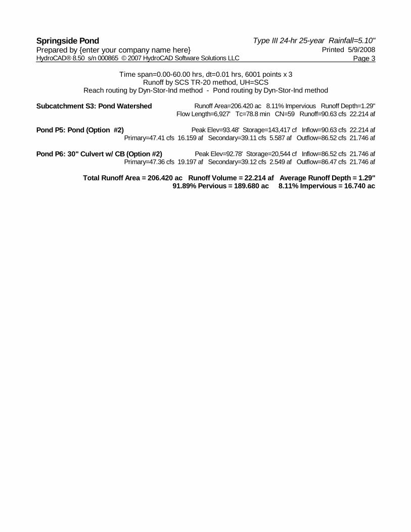
Type III 24-hr 25-year Rainfall=5.10"Springside Pond Printed 5/9/2008Prepared by {enter your company name here}
Page 3HydroCAD® 8.50 s/n 000865 © 2007 HydroCAD Software Solutions LLC
Time span=0.00-60.00 hrs, dt=0.01 hrs, 6001 points x 3Runoff by SCS TR-20 method, UH=SCS
Reach routing by Dyn-Stor-Ind method - Pond routing by Dyn-Stor-Ind method
Runoff Area=206.420 ac 8.11% Impervious Runoff Depth=1.29"Subcatchment S3: Pond Watershed Flow Length=6,927' Tc=78.8 min CN=59 Runoff=90.63 cfs 22.214 af
Peak Elev=93.48' Storage=143,417 cf Inflow=90.63 cfs 22.214 afPond P5: Pond (Option #2) Primary=47.41 cfs 16.159 af Secondary=39.11 cfs 5.587 af Outflow=86.52 cfs 21.746 af
Peak Elev=92.78' Storage=20,544 cf Inflow=86.52 cfs 21.746 afPond P6: 30" Culvert w/ CB (Option #2) Primary=47.36 cfs 19.197 af Secondary=39.12 cfs 2.549 af Outflow=86.47 cfs 21.746 af
Total Runoff Area = 206.420 ac Runoff Volume = 22.214 af Average Runoff Depth = 1.29"91.89% Pervious = 189.680 ac 8.11% Impervious = 16.740 ac

Type III 24-hr 50-year Rainfall=5.90"Springside Pond Printed 5/9/2008Prepared by {enter your company name here}
Page 4HydroCAD® 8.50 s/n 000865 © 2007 HydroCAD Software Solutions LLC
Time span=0.00-60.00 hrs, dt=0.01 hrs, 6001 points x 3Runoff by SCS TR-20 method, UH=SCS
Reach routing by Dyn-Stor-Ind method - Pond routing by Dyn-Stor-Ind method
Runoff Area=206.420 ac 8.11% Impervious Runoff Depth=1.78"Subcatchment S3: Pond Watershed Flow Length=6,927' Tc=78.8 min CN=59 Runoff=130.75 cfs 30.535 af
Peak Elev=93.80' Storage=162,438 cf Inflow=130.75 cfs 30.535 afPond P5: Pond (Option #2) Primary=66.18 cfs 20.755 af Secondary=60.68 cfs 9.312 af Outflow=126.86 cfs 30.067 af
Peak Elev=92.94' Storage=22,841 cf Inflow=126.86 cfs 30.067 afPond P6: 30" Culvert w/ CB (Option #2) Primary=48.16 cfs 23.178 af Secondary=78.67 cfs 6.888 af Outflow=126.82 cfs 30.067 af
Total Runoff Area = 206.420 ac Runoff Volume = 30.535 af Average Runoff Depth = 1.78"91.89% Pervious = 189.680 ac 8.11% Impervious = 16.740 ac

Type III 24-hr 100-year Rainfall=6.40"Springside Pond Printed 5/9/2008Prepared by {enter your company name here}
Page 5HydroCAD® 8.50 s/n 000865 © 2007 HydroCAD Software Solutions LLC
Time span=0.00-60.00 hrs, dt=0.01 hrs, 6001 points x 3Runoff by SCS TR-20 method, UH=SCS
Reach routing by Dyn-Stor-Ind method - Pond routing by Dyn-Stor-Ind method
Runoff Area=206.420 ac 8.11% Impervious Runoff Depth=2.10"Subcatchment S3: Pond Watershed Flow Length=6,927' Tc=78.8 min CN=59 Runoff=157.68 cfs 36.105 af
Peak Elev=94.00' Storage=174,084 cf Inflow=157.68 cfs 36.105 afPond P5: Pond (Option #2) Primary=78.62 cfs 23.700 af Secondary=75.14 cfs 11.936 af Outflow=153.76 cfs 35.637 af
Peak Elev=93.03' Storage=24,226 cf Inflow=153.76 cfs 35.637 afPond P6: 30" Culvert w/ CB (Option #2) Primary=48.61 cfs 25.419 af Secondary=105.10 cfs 10.218 af Outflow=153.71 cfs 35.637 af
Total Runoff Area = 206.420 ac Runoff Volume = 36.105 af Average Runoff Depth = 2.10"91.89% Pervious = 189.680 ac 8.11% Impervious = 16.740 ac
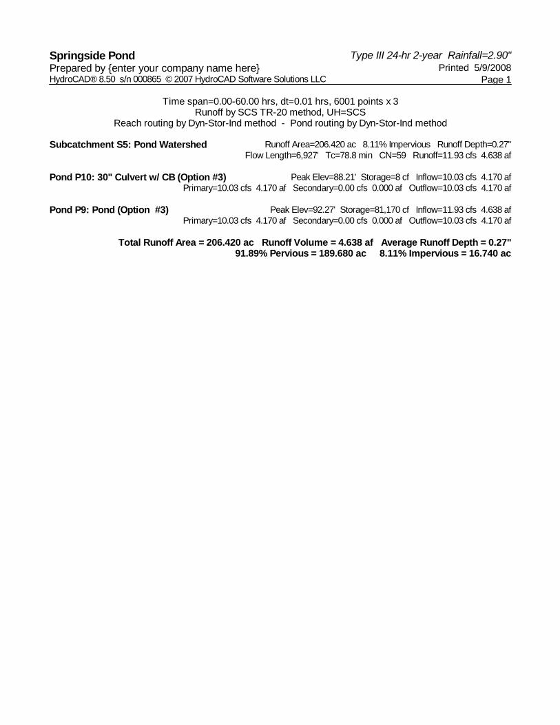
Type III 24-hr 2-year Rainfall=2.90"Springside Pond Printed 5/9/2008Prepared by {enter your company name here}
Page 1HydroCAD® 8.50 s/n 000865 © 2007 HydroCAD Software Solutions LLC
Time span=0.00-60.00 hrs, dt=0.01 hrs, 6001 points x 3Runoff by SCS TR-20 method, UH=SCS
Reach routing by Dyn-Stor-Ind method - Pond routing by Dyn-Stor-Ind method
Runoff Area=206.420 ac 8.11% Impervious Runoff Depth=0.27"Subcatchment S5: Pond Watershed Flow Length=6,927' Tc=78.8 min CN=59 Runoff=11.93 cfs 4.638 af
Peak Elev=88.21' Storage=8 cf Inflow=10.03 cfs 4.170 afPond P10: 30" Culvert w/ CB (Option #3) Primary=10.03 cfs 4.170 af Secondary=0.00 cfs 0.000 af Outflow=10.03 cfs 4.170 af
Peak Elev=92.27' Storage=81,170 cf Inflow=11.93 cfs 4.638 afPond P9: Pond (Option #3) Primary=10.03 cfs 4.170 af Secondary=0.00 cfs 0.000 af Outflow=10.03 cfs 4.170 af
Total Runoff Area = 206.420 ac Runoff Volume = 4.638 af Average Runoff Depth = 0.27"91.89% Pervious = 189.680 ac 8.11% Impervious = 16.740 ac

Type III 24-hr 10-year Rainfall=4.40"Springside Pond Printed 5/9/2008Prepared by {enter your company name here}
Page 2HydroCAD® 8.50 s/n 000865 © 2007 HydroCAD Software Solutions LLC
Time span=0.00-60.00 hrs, dt=0.01 hrs, 6001 points x 3Runoff by SCS TR-20 method, UH=SCS
Reach routing by Dyn-Stor-Ind method - Pond routing by Dyn-Stor-Ind method
Runoff Area=206.420 ac 8.11% Impervious Runoff Depth=0.91"Subcatchment S5: Pond Watershed Flow Length=6,927' Tc=78.8 min CN=59 Runoff=59.80 cfs 15.650 af
Peak Elev=92.57' Storage=17,779 cf Inflow=56.64 cfs 15.182 afPond P10: 30" Culvert w/ CB (Option #3) Primary=46.30 cfs 15.054 af Secondary=4.53 cfs 0.129 af Outflow=50.82 cfs 15.182 af
Peak Elev=92.90' Storage=111,922 cf Inflow=59.80 cfs 15.650 afPond P9: Pond (Option #3) Primary=49.66 cfs 14.302 af Secondary=11.67 cfs 0.881 af Outflow=56.64 cfs 15.182 af
Total Runoff Area = 206.420 ac Runoff Volume = 15.650 af Average Runoff Depth = 0.91"91.89% Pervious = 189.680 ac 8.11% Impervious = 16.740 ac
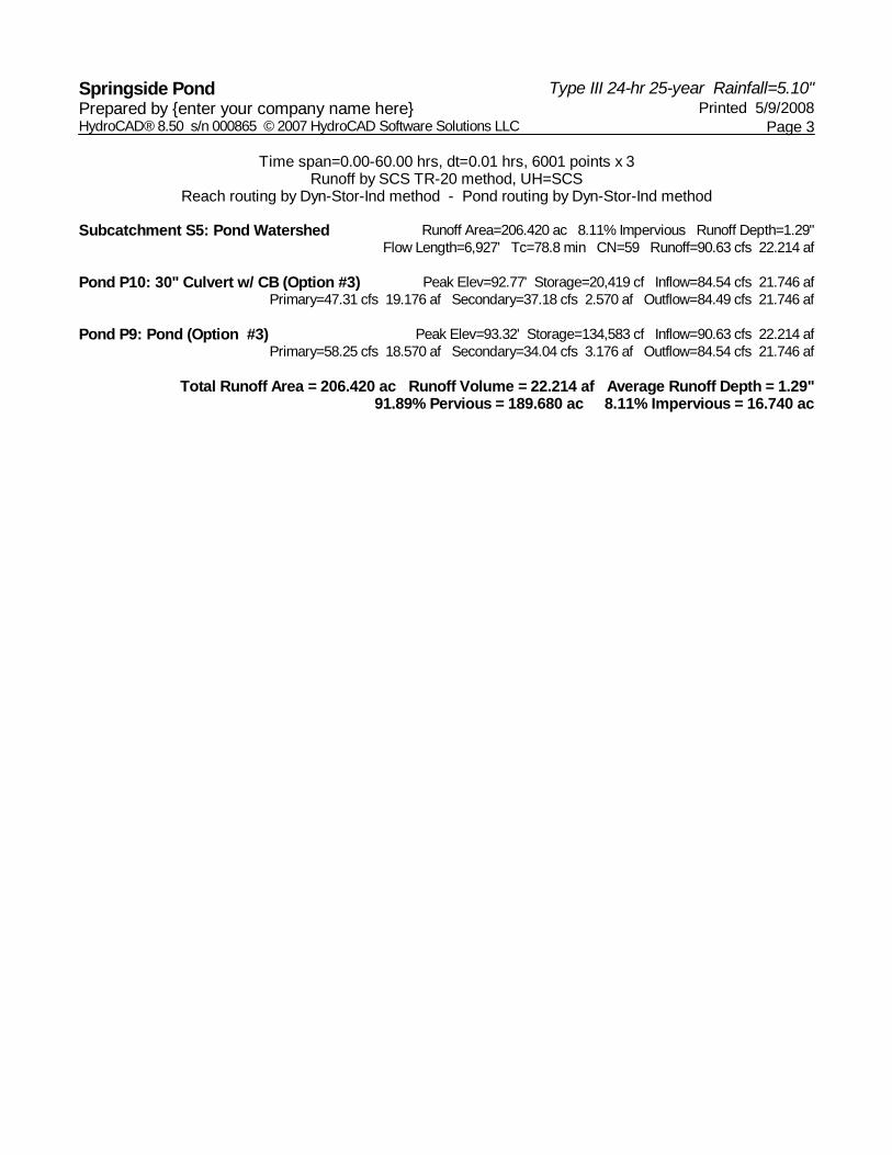
Type III 24-hr 25-year Rainfall=5.10"Springside Pond Printed 5/9/2008Prepared by {enter your company name here}
Page 3HydroCAD® 8.50 s/n 000865 © 2007 HydroCAD Software Solutions LLC
Time span=0.00-60.00 hrs, dt=0.01 hrs, 6001 points x 3Runoff by SCS TR-20 method, UH=SCS
Reach routing by Dyn-Stor-Ind method - Pond routing by Dyn-Stor-Ind method
Runoff Area=206.420 ac 8.11% Impervious Runoff Depth=1.29"Subcatchment S5: Pond Watershed Flow Length=6,927' Tc=78.8 min CN=59 Runoff=90.63 cfs 22.214 af
Peak Elev=92.77' Storage=20,419 cf Inflow=84.54 cfs 21.746 afPond P10: 30" Culvert w/ CB (Option #3) Primary=47.31 cfs 19.176 af Secondary=37.18 cfs 2.570 af Outflow=84.49 cfs 21.746 af
Peak Elev=93.32' Storage=134,583 cf Inflow=90.63 cfs 22.214 afPond P9: Pond (Option #3) Primary=58.25 cfs 18.570 af Secondary=34.04 cfs 3.176 af Outflow=84.54 cfs 21.746 af
Total Runoff Area = 206.420 ac Runoff Volume = 22.214 af Average Runoff Depth = 1.29"91.89% Pervious = 189.680 ac 8.11% Impervious = 16.740 ac

Type III 24-hr 50-year Rainfall=5.90"Springside Pond Printed 5/9/2008Prepared by {enter your company name here}
Page 4HydroCAD® 8.50 s/n 000865 © 2007 HydroCAD Software Solutions LLC
Time span=0.00-60.00 hrs, dt=0.01 hrs, 6001 points x 3Runoff by SCS TR-20 method, UH=SCS
Reach routing by Dyn-Stor-Ind method - Pond routing by Dyn-Stor-Ind method
Runoff Area=206.420 ac 8.11% Impervious Runoff Depth=1.78"Subcatchment S5: Pond Watershed Flow Length=6,927' Tc=78.8 min CN=59 Runoff=130.75 cfs 30.535 af
Peak Elev=92.93' Storage=22,720 cf Inflow=124.60 cfs 30.067 afPond P10: 30" Culvert w/ CB (Option #3) Primary=48.12 cfs 23.134 af Secondary=76.44 cfs 6.933 af Outflow=124.55 cfs 30.067 af
Peak Elev=93.73' Storage=158,198 cf Inflow=130.75 cfs 30.535 afPond P9: Pond (Option #3) Primary=63.12 cfs 23.211 af Secondary=63.76 cfs 6.857 af Outflow=124.60 cfs 30.067 af
Total Runoff Area = 206.420 ac Runoff Volume = 30.535 af Average Runoff Depth = 1.78"91.89% Pervious = 189.680 ac 8.11% Impervious = 16.740 ac

Type III 24-hr 100-year Rainfall=6.40"Springside Pond Printed 5/9/2008Prepared by {enter your company name here}
Page 5HydroCAD® 8.50 s/n 000865 © 2007 HydroCAD Software Solutions LLC
Time span=0.00-60.00 hrs, dt=0.01 hrs, 6001 points x 3Runoff by SCS TR-20 method, UH=SCS
Reach routing by Dyn-Stor-Ind method - Pond routing by Dyn-Stor-Ind method
Runoff Area=206.420 ac 8.11% Impervious Runoff Depth=2.10"Subcatchment S5: Pond Watershed Flow Length=6,927' Tc=78.8 min CN=59 Runoff=157.68 cfs 36.105 af
Peak Elev=93.02' Storage=24,099 cf Inflow=151.22 cfs 35.637 afPond P10: 30" Culvert w/ CB (Option #3) Primary=48.57 cfs 25.373 af Secondary=102.60 cfs 10.264 af Outflow=151.17 cfs 35.637 af
Peak Elev=93.98' Storage=172,948 cf Inflow=157.68 cfs 36.105 afPond P9: Pond (Option #3) Primary=66.40 cfs 25.968 af Secondary=84.82 cfs 9.669 af Outflow=151.22 cfs 35.637 af
Total Runoff Area = 206.420 ac Runoff Volume = 36.105 af Average Runoff Depth = 2.10"91.89% Pervious = 189.680 ac 8.11% Impervious = 16.740 ac