sprayfineÔ operator's manual - turbine … pour the diluted material (paint, coating, etc.)...
TRANSCRIPT

SPRAYFINE OPERATOR'S MANUAL
Thank you for choosing Sprayfine HVLP (High-Volume Low-Pressure) sprayers for your spraying needs. AtTurbine Products Inc., we take pride in our precision-engineered products and want you to obtain all the benefits thatyour Sprayfine sprayer has to offer.
To ensure the proper use and maintenance of your Sprayfine sprayer, please carefully read the informationcontained in this manual before using your system. Should you require any further information, please contact yournearest Sprayfine distributor, or Turbine Products Inc. directly for assistance - we will be pleased to assist you.

2
IMPORTANT: READ BEFORE USING
SAFETY PRECAUTIONS
EXPLOSION AND FIRE HAZARD - Solvent and paint fumes can explode or ignite causing property damage and/orsevere injury.• Spray area must be well ventilated and free from flames, hot objects, cigarettes, pilot lights and sparks (sparks
can occur from static electricity, operating light switches, operating power equipment, andconnecting/disconnecting power cords).
• Keep turbine maximum possible distance from spray area.• Power cord must be connected to a grounded outlet.• Fire extinguishing equipment must be present and in working order.• Follow safety precautions and warnings on paint and solvent containers.
EXPLOSION HAZARD – Incompatible materials may cause property damage and/or severe injury.• Do not use bleach• DO NOT use halogenated hydrocarbon solvents such as methylene chloride and 1,1,1 Trichlorethane. These
materials are not compatible with aluminum and may cause an explosion. Contact your coatings supplier toensure all solvents used are compatible with aluminum
• DO NOT leave solvents in a sealed aluminum paint cup
SKIN BURN HAZARD – Hot parts can cause severe skin burn injury.• Metal fittings on the turbine unit and air hose can become hot during use. Avoid skin contact with metal fittings
when they are hot.
ELECTRC SHOCK HAZARD – May cause severe injury or death• To reduce the risk of electric shock, do not expose turbine unit to rain or water. Store indoors.
RISK OF BURSTING – May cause property damage or severe injury• Use only authorized parts that are rated for pressure not less than 10 psi.
HAZARDOUS VAPORS – Paints, solvents and other materials may be harmful if inhaled causing severe illness,fainting or poisoning.• Use a respirator when operating the turbine. Read all instructions to ensure the respirator will provide the
necessary protection against the inhalation of harmful vapors.
GENERAL – May cause property damage or severe injury.• Read all instructions and safety precautions before operating any equipment.• Comply with all appropriate local, state and national codes governing ventilation, fire prevention, and operation.• United States Government Safety Standards have been adopted under the Occupational Safety and Health ACT
(OSHA). These standards, particularly Part 1910 of the General Standards and Part 1926 of the ConstructionStandard should be consulted.
• This equipment is designed to be used with authorized parts only. When using this equipment with parts that donot comply with the minimum specifications and safety devices of the equipment manufacturer, the userassumes all risks and liabilities
• Check all hoses for cuts, leaks, abrasion or bulging, as well as damage or movement of fittings before each use.If any of these conditions exist, replace the hose immediately. Do not repair a hose.
• Never aim the spray gun at any part of the body.

3
IMPORTANT OPERATING TIPS
• Most sprayable coatings must be thinned (diluted) to be sprayed. Always follow the paint or coatingmanufacturer’s instructions regarding thinning solvents and dilution ratios when preparing the coating to besprayed.
• Select the appropriate needle, nozzle and air cap based on the coating being sprayed, the film thicknessrequired, and the application speed and finish required.
• For optimum results, always test spraying distance, pattern size, coating thickness, needle/nozzle/air capcombination and finish, on a sample of the surface to be coated.
• When using a cup gun, do not turn the gun upside-down. The tube that pressurizes the paint cup is internaland if blocked, will prevent the pressurization of the paint cup.
• Make sure you clean your spray gun after each use as outlined in this manual. Proper cleaning is essential toensure the smooth operation of your system.
GETTING STARTED
TESTING THE TURBINE
With the power switch in the OFF position, place the turbine as far away from the spray area as comfortably possibleand plug into a standard (110-120 volt) power outlet. Verify that the turbine foam air filters are properly covering themotor air vents on either side of the turbine cabinet. Turn the turbine ON and ensure that air is blowing out the airoutlet.
All Sprayfine systems are equipped with a 15-amp fuse. If the turbine is not functioning properly, check your powersupply and/or replace the fuse.
NOTE: Due to the high speed of the turbine (18,000 to 24,000 RPM) and the frictional forces this causes, it is normalfor the turbine, hose and gun to heat up slightly during operation. Generally, the system will heat up and then remainat a constant temperature during use.
CONNECTING THE HOSE TO THE TURBINE
With the power switch in the OFF position, uncoil the air hose and screw it hand-tight to the turbine air outlet.
Although the hose is designed for industrial use, it is not crushproof. Do not stand on the hose for extended periods.The hose should never be used to pull the turbine or form a sharp angle at the air outlet – this can cause prematurewear of the hose, restriction of the airflow and/or overheating of the hose.
CONNECTING THE SPRAY GUN AND TEST SPRAY
Always ensure that the gun is clean prior to being used. Any paint residue and/or particles left in the paint cup and/orfluid tubes from previous use can spoil a finish and possibly affect the performance of your sprayer.
Using the information provided on pages 5 and 6 of this manual, determine whether the needle, nozzle and air capcombination in the gun is suitable as a starting point for your application. If not, refer to page 6 of this manual forneedle, nozzle and air cap selection, and page 13 for instructions on changing the needle, nozzle and air cap.

4
To install the hose on the gun, pull back the ring on the quick disconnect coupler to connect it to the male tailpieceon the end of the gun handle.
For proper testing prior to spraying, refer to page 8 of this manual.
GENERAL OPERATING INSTRUCTIONS
OPERATING INSTRUCTIONS AND PAINTING TIPS
The following general instructions are meant to be a guideline for success with your Sprayfine sprayer. Althoughpractice makes perfect, there are a number of books, videos and courses available on the market to help you furtherrefine your knowledge and skills of spraying in general, should you wish to do so.
PAINT PREPARATION AND VISCOSITY CHART
Most coatings must be thinned (diluted) to be sprayed. Always follow the paint or coating manufacturers’instructions regarding thinning solvents and dilution ratios when preparing the coating to be sprayed. Always mix andstore your thinned material in a separate container, and label your containers based on original coating, thinningsolvent used and percent dilution.
The thickness of a coating is defined by its "viscosity in seconds": "viscous coatings" are thicker materials; "non-viscous coatings" are thinner materials. To properly measure the viscosity of a coating, use a viscosity cup.
Completely submerge the viscosity cup in the coating to be measured
Lift the viscosity cup out of the coating and begin timing.
Measure the time in seconds until the first break in the stream of coating
The time lapsed will determine the viscosity of the coating, i.e.: 25 seconds.
Once you have prepared the estimated quantity of coating required, select an appropriate needle/nozzle/air capcombination for use with the coating.
Once you have selected and installed the appropriate size needle, nozzle and air cap, detach the paint cup from thegun, pour the diluted material (paint, coating, etc.) through a cone filter into the cup, and re-attach it to the gun.
For optimum results, always test coating viscosity, spraying distance, pattern size, film thickness, needle/nozzle/aircap combination and finish, on a sample of the surface to be coated.

5
Viscosity Chart
Properties and thickness of coatings vary from one manufacturer to another. The following chart is a guideline only.Use these times as a guideline in determining the appropriate viscosity based on your spraying technique and finishstandards. Some high solids coatings may exceed a reasonable viscosity and still be sprayable.
Material To Be Sprayed Time To First Break In Stream
Acrylic FinishesAcrylic MetallicAcrylic PrimerAdhesivesAutomotive LacquerChromatesDyesEnamelHammer FinishesHard Gloss SyntheticsImronLacquerLatexMarine PaintMasonry PaintOil-bound Heavy-bodiedPrimersPolyurethane PaintStains
10-15 seconds10-15 seconds20-40 seconds40-60 seconds20-30 seconds20-25 seconds10-20 seconds25-50 seconds30-40 seconds30-40 seconds30-45 seconds10-30 seconds30-45 seconds30-45 seconds30-50 seconds35-40 seconds20-40 seconds10-20 seconds20-25 seconds
NEEDLE, NOZZLE AND AIR CAP SELECTION
The proper needle, nozzle and air cap combination is critical to the optimal performance of any spraying system.Needles and nozzles are sized together – when changing the needle, the nozzle must be changed as well. Air capsare sized separately and can be changed without necessarily changing the needle and nozzle. Turbine Products Inc.manufacturers five different sizes of needles/nozzles/air caps ranging from 1.0mm to 2.0mm
Selecting The Proper Needle, Nozzle, And Air Cap Combination
To select the proper needle and nozzle, start with the needle and nozzle selection chart below. Needles and nozzlesrange in size and should be selected based on the viscosity of the coating being applied and the finish andapplication speed required. For non-viscous materials (thin viscosity), select a smaller size needle and nozzle. Forviscous materials (thick viscosity), select a larger size needle and nozzle. For best results, use the needle and nozzlethat performs best with the trigger of the gun fully engaged.
To select the proper air cap, consider the size of the needle and nozzle, and finish required. The size of the air cap isdetermined by the size of its center hole. In order for the air to atomize the coating, the hole in the center of the aircap must be large enough to allow air to flow freely around the nozzle. Depending on the size of the nozzle, you mayhave a choice of air caps: using a larger size air cap may eliminate more overspray (mist), however using a smallersize air cap may produce a finer finish.

6
Needle And Nozzle Selection Chart
Material Viscosity Needle and Nozzle
Wood Stains, Lacquers, Automotive, Cellulose,Synthetics, Acrylic, Oil
0-20 sec 1.00mm
Polyurethane, Glitter Paints, Cellulose, Acrylics,Synthetics, Lacquers, Fluorescents, Wood Stains,Creosote, Wood Primer
20-30 sec 1.30mm
Oil Base, Oxides, Primers, Marine Paint, Varnish,Enamels, Multi-Color, Industrial Synthetics
30-35 sec 1.50mm
Emulsions, Oxides, Chlorinated Rubber, Zinc RichPrimers
35-40 sec 1.80mm
Hammers, Latex, Oil Base Primers, Enamels,Marine, Masonry Paints, Texture Coatings, HeavyPrimers, Water and Solvent Based Adhesives
40+ sec 2.00mm
SURFACE PREPARATION
Ensure that the surface you are spraying is clean, dry, and free from dust, oil, grease or any other contaminant. Adirty or greasy surface will affect adhesion, can spoil a finish and is very difficult to correct once sprayed. If possible,always clean the surface with a tack rag to remove any dust or lint. Do not wipe the surface with your hand – body oilmay stay on the part and ruin the surface preparation.
OPERATING THE TURBINE
All Sprayfine turbines are equipped with a lighted On/Off rocker switch. If power is available to the unit, the rockerswitch will be illuminated
All Sprayfine turbines are equipped with a 15-amp fuse. If the turbine is not functioning properly, check your powersupply and/or replace the fuse.
NOTE: Due to the high speed of the turbine, and the compression of air, the turbine, hose and gun will heat upslightly during operation. The system will heat up and then remain at a constant temperature during use.

7
SPRAY GUN PARTS LIST
Spray Pattern Selection
To select the desired spray pattern, rotate the air cap at the front of the gun. When the air cap is in the diagonalposition, the spray pattern will be round; when in the horizontal position, the spray pattern will be vertical; and whenin the vertical position, the spray pattern will be horizontal.

8
To adjust the size of the pattern, screw the air cap ring in or out accordingly. Turning the ring clockwise will makethe pattern bigger, and will decrease the atomization. Turning the ring counterclockwise will make the patternssmaller and will increase the atomization. CAUTION: When adjusting the size of the spray pattern, moving the aircap too close to the nozzle may cause an undesirable figure-8 pattern; moving the air cap too far from the nozzle willeventually prevent spraying altogether.
To Begin Spraying
Switch the turbine power switch to the ON position.
To control the thickness of the coat being applied, slowly turn the material flow adjustment screw (at rear of gun)counter-clockwise while squeezing the trigger of the gun. Continue turning the screw until the appropriate materialflow has been achieved to provide the desired coating thickness and finish. For best results, select the needle,nozzle and air cap combination that allows you to have the trigger fully engaged.
Maintain a consistent distance of 6-8 inches from the surface and spray in a smooth continuous motion.
The direction of the spraying motion should be based on the spray pattern chosen: when spraying a horizontalpattern, the direction should be up and down; when spraying a vertical pattern, the direction should be left to right orright to left; when spraying a round pattern, the direction can be either.
CAUTION: Once you have filled the spray gun, it is important to keep the gun upright. You may tilt the gun asnecessary to spray a ceiling or tabletop for example, but note that the tube that pressurizes the paint cup is internal.Do not turn the gun on it side or upside down when there is paint in the cup as the paint may block the air holesand prevent the pressurization of the paint cup. If you will be spraying with the gun in a non-upright orientation, usethe optional remote cup assembly.
TESTING PRIOR TO SPRAYING
• For optimum results, always test coating viscosity, spraying distance, pattern size, film thickness,needle/nozzle/air cap combination and finish, on a sample of the surface to be coated.
• To test the proper application speed (speed of your hand), spray one pass on a sample of the surface tobe coated at a consistent speed. Examine the sprayed coating: if there appears to be space between thedroplets of paint, slow down your application speed; if individual droplets are not visible and the film seemseven, note the application speed and maintain it throughout use.
• To test the Needle/Nozzle/Air Cap combination and to ensure even film thickness (coat of materialbeing applied), use the horizontal spray pattern test:
Horizontal Spay Pattern Test
1. Turn the air cap to the vertical position – this will spray a horizontal pattern.
2. Maintaining the distance of 6-8" from the surface, squeeze the trigger and spray a horizontal pattern on thesame spot until the material has built up enough to sag.
3. Release the trigger and point the gun away from the surface.
4. Repeat steps 1-3 about three to five times in different areas of the test piece.
Watch the material sag and see if it runs (drips) evenly across the spray pattern. If so, your needle, nozzle and aircap combination are correct. If not, identify a common problem with all the test patterns sprayed and refer to thefollowing troubleshooting chart:

9
Problem Solution
• Coating is running/dripping from thecenter of the pattern
• Air cap may be too large: try smallersize air cap
• Coating is running/dripping from theextremities of the pattern
• Air cap may be too small: try larger sizeair cap
• Pattern is in the form of a figure 8 • Air cap may be too small: try larger sizeair cap
• Air cap may be too close to the nozzle:turn the air cap ring slightly to move aircap further from nozzle
Even Drip Even Drip Figure 8
Running/Dripping FromExtremities Running/Dripping From Center
BASIC SPRAYING TECHNIQUES
For applications where thicker coats are required and finish quality is critical, consider applying two thinner coats.The reduction in paint consumption and drying time when spraying with Sprayfine systems often justifies theadditional step.

10
• Hold the gun perpendicular to the surface being sprayed, maintain a consistent distance from the surface(approx. 6-8"/15-20cm), and spray with a smooth continuous motion.
• Overlap strokes up to 50% to ensure proper coverage and avoid streaks.
Overlap successive strokes
• Select the needle and nozzle that performs best with the trigger of the gun fully engaged.
• When spraying odd shaped objects, spray hard to reach areas, curved surfaces, and corners and edges first,spray flat surfaces second.
• When spraying an outside edge or corner, split the center of the spray pattern on the corner or edge so thateach side receives 50% of the spray pattern and equal amounts of paint.
Spraying an outside edge or corner
11
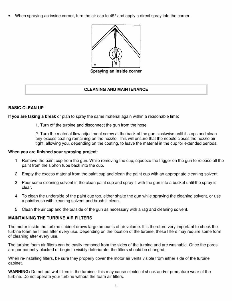
• When spraying an inside corner, turn the air cap to 45° and apply a direct spray into the corner.
Spraying an inside corner
CLEANING AND MAINTENANCE
BASIC CLEAN UP
If you are taking a break or plan to spray the same material again within a reasonable time:
1. Turn off the turbine and disconnect the gun from the hose.
2. Turn the material flow adjustment screw at the back of the gun clockwise until it stops and cleanany excess coating remaining on the nozzle. This will ensure that the needle closes the nozzle airtight, allowing you, depending on the coating, to leave the material in the cup for extended periods.
When you are finished your spraying project:
1. Remove the paint cup from the gun. While removing the cup, squeeze the trigger on the gun to release all thepaint from the siphon tube back into the cup.
2. Empty the excess material from the paint cup and clean the paint cup with an appropriate cleaning solvent.
3. Pour some cleaning solvent in the clean paint cup and spray it with the gun into a bucket until the spray isclear.
4. To clean the underside of the paint cup top, either shake the gun while spraying the cleaning solvent, or usea paintbrush with cleaning solvent and brush it clean.
5. Clean the air cap and the outside of the gun as necessary with a rag and cleaning solvent.
MAINTAINING THE TURBINE AIR FILTERS
The motor inside the turbine cabinet draws large amounts of air volume. It is therefore very important to check theturbine foam air filters after every use. Depending on the location of the turbine, these filters may require some formof cleaning after every use.
The turbine foam air filters can be easily removed from the sides of the turbine and are washable. Once the poresare permanently blocked or begin to visibly deteriorate, the filters should be changed.
When re-installing filters, be sure they properly cover the motor air vents visible from either side of the turbinecabinet.
WARNING: Do not put wet filters in the turbine - this may cause electrical shock and/or premature wear of theturbine. Do not operate your turbine without the foam air filters.

12
COMPLETE DISASSEMBLY AND CLEANING OF SPRAY GUN
Periodically, especially after spraying an adhesive, a catalyzed coating, or any other material that is known to bedifficult to clean, Turbine Products Inc. recommends that you completely disassemble your gun and clean each partindividually.
To Clean And Disassemble The Gun:
1. Remove the paint cup from the gun. While removing the cup, squeeze the trigger on the gun to release all thepaint from the siphon tube back into the cup.
2. Empty the excess material from the paint cup and clean the paint cup with an appropriate cleaning solvent.
3. Pour some cleaning solvent in the clean paint cup and spray it with the gun into a bucket until the spray isclear. Remove the paint cup from the gun.
4. Completely unscrew the material flow adjustment screw at the back of the gun and remove the spring andneedle – if necessary, squeeze the trigger to help remove the needle.
5. Using the opened end of a 7/16" combination wrench, remove the gland nut located directly in front of thetrigger, and remove the gland seal.
6. Completely unscrew the air cap ring on the barrel of the gun and remove the air cap, spring plate, and spring.
7. Using a needlenose pliers, remove the nozzle.
To Clean Parts Individually And Replace Gaskets:
1. Soak all dirty parts in clean cleaning solvent (nozzle, tip of needle, siphon tube extension, etc.). If necessary,soak the entire gun body.
2. Using the gun cleaning brush, clean the inside of the siphon tube, siphon tube extension, and all fluidpassages.
3. Remove the cup top gasket. Using the gun cleaning brush, a paintbrush (if necessary), and cleaning solvent,clean the underside of the paint cup top, and install a new cup top gasket.
4. When re-assembling the paint cup top assembly, be sure that the air tube protruding from the gun body is notblocked, and install a new cup top washer between the cup top and the gun body.
5. Before re-installing the gland nut, install a new gland seal to seal the fluid passage – ensure that the glandseal is seated properly before installing the gland nut. If not properly installed, this may cause leakingbetween the gland nut and the needle directly in front of the gun trigger.
Do not use hardened needles or picks to clean the holes of the nozzle or the air cap. This may enlarge the holes ofthese critical parts and affect the performance of your system when used.
When re-assembling the gun, it is recommended to apply a little white grease or petroleum jelly on all threaded andtight tolerance parts: material flow adjustment screw and spring; spring plate; air cap ring; tip of needle.

13
CHANGING THE NEEDLE, NOZZLE AND AIR CAP
Select the needle, nozzle and air cap combination based on the coating being sprayed, the application speed andfinish required. Select the combination that performs best with the trigger fully engaged.
Needles and nozzles are sized together – when changing the needle, the nozzle must be changed as well. Air capsare sized separately and can be changed without changing the needle and nozzle:
1. To Change The Needle: Completely unscrew the material flow adjustment screw at the back of the gun andremove the spring and needle – if necessary, squeeze the trigger to help remove the needle.
2. To Change The Nozzle: Completely unscrew the air cap ring on the barrel of the gun and remove the aircap, spring plate, and spring. Using a needlenose pliers, remove the nozzle.
3. To Change The Air Cap: Completely unscrew the air cap ring on the barrel of the gun and remove the aircap.
4. To re-install the Spring plate To re-install the spring plate after changing the nozzle and/or air cap:
1. Place the spring in the barrel of the gun.
2. Place the spring plate on the spring with the recessed side inward, and the ball guide lined up with the groovein the housing.
3. Press the spring plate into the housing, making sure that the ball guide is sliding into the groove in thehousing, and hold it in place.
4. Slide the air cap over the spring plate, and hold it in place.
5. Place the air cap ring on your index finger. Use the tip of the same index finger to hold the air cap on thespring plate and screw the air cap ring in place.
REPLACING THE CUP TOP GASKET
The cup top gasket on the underside of the cup top should be replaced periodically as part of preventivemaintenance. A worn cup top gasket can be the cause of material leaking from the paint cup and/or bubbling underthe paint cup top when the gun is in use.
To Replace The Cup Top Gasket:
1. Remove the paint cup from the gun.
2. Remove the cup top gasket using a pointed object or screwdriver.
3. Replace with a new gasket, making sure it is placed flat and properly pressed in place.
REPLACING THE GLAND SEAL
The gland seal is located behind the gland nut directly in front of the gun trigger and should be replaced periodicallyas part of preventive maintenance. A worn gland seal can be the cause of leaking between the gland nut and theneedle directly in front of the trigger. If leaking occurs, try tightening the gland nut before changing the gland seal.

14
To Replace The Gland Seal:
1. Remove the material flow adjustment screw, spring and needle from the back of the gun.
2. Using the opened end of a 7/16" combination wrench, remove the gland nut.
3. Being careful not to damage the threads of the gland nut chamber, remove the gland seal using a hardenedneedle or pick.
4. Replace the gland seal and re-install the gland nut.
5. Re-install the needle, spring and material flow adjustment screw.
Tighten the gland nut as much as possible without restricting the free movement of the trigger. If the gun continues tospray after the trigger is released, the gland nut is too tight. If material leaks out between the gland nut and theneedle directly in front of the trigger, the gland nut is too loose. Adjust accordingly.
BASIC TROUBLESHOOTING CHART
Problem Probable Cause Solution(s)
Turbine not working at all
A. No power to the
turbine
B. Fuse is blown
A. Check poweroutlet/socket
B. Replace fuse
Low Air Flow A. Filters are blocked
B. Turbine air vents areobstructed
C. Kink in hose
D. Broken or damagedhose
E. Motor outlet leakingair: gasket is worn
A. Clean or replace filtersas necessary
B. Allow air to flow freelyaround turbine
C. Remove kink andstraighten hose
D. Inspect hose: repair orreplace if necessary
E. Open turbine cabinetand inspect: replace ifpossible or contactTurbine Products Inc.
Turbine/Hose/GunOverheating
A. Ambient air is hot
B. Turbine foam filtersare blocked
C. Turbine air vents areobstructed
D. Due to speed ofturbine motor, systemnormally gets warm
A. Use in coolerenvironment if possible
B. Clean or replace filtersas necessary
C. Allow air to flow freelyaround turbine
D. Additional lengths ofhose will reduce heatbuild-up in gun
E. Wear gloves

15
Uneven Spray Pattern A. Air cap holes plugged
B. Dry paint on nozzle
C. Incorrectneedle/nozzle/air capcombination
D. "Figure 8": air cap tooclose to nozzle
A. Clean or replace aircap as necessary
B. Clean nozzle andcontinue spraying
C. See page 6 for properselection and testing
D. Turn air cap ringcounter-clockwise tomove air cap awayfrom nozzle
Fluid Leaking From Paint Cupand/or Bubbling In Paint Cup
A. Cup top gasket notsealing properly
A. Tighten cup or replacecup top gasket
Fluid Leaking Between GlandNut And Needle Directly InFront Of Trigger
A. Gland nut too loose
B. Gland seal worn
A. Tighten gland nut
B. Replace gland seal
Not Spraying At All orInconsistent Material Flow(spitting) With A Cup Gun
A. Air cap too far fromnozzle
B. Dry paint on end ofnozzle
C. Coating is too thick:not enough pressureto pump from cup tonozzle
D. Foreign/unwantedparticles in the coating
E. Air tube blocked:preventingpressurization of paintcup
F. Cup top gasket notsealing properly
G. Not enough paint incup
A. Turn air cap ringclockwise to move aircap closer to nozzle
B. Clean nozzle andcontinue spraying
C. Add more thinningsolvent if possible
D. Empty cup; clean gunproperly filter materialwhen pouring back intocup
E. Disassemble andclean spray gun
F. Tighten cup or replacecup top gasket
G. Check level and add
Not Spraying At All orInconsistent Material Flow(spitting) With A Pressure-FedGun
A. Air cap too far fromnozzle
B. Dry paint on end ofnozzle
A. Insufficient pressure inpaint cup
B. Fluid line blocked
A. Turn air cap ringclockwise to move aircap closer to nozzle
B. Clean nozzle andcontinue spraying
C. Increase pressure inpaint cup
D. Disconnect fluid line
16
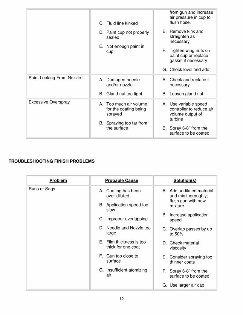
C. Fluid line kinked
D. Paint cup not properlysealed
E. Not enough paint incup
from gun and increaseair pressure in cup toflush hose.
E. Remove kink andstraighten asnecessary
F. Tighten wing nuts onpaint cup or replacegasket if necessary
G. Check level and add
Paint Leaking From Nozzle A. Damaged needleand/or nozzle
B. Gland nut too tight
A. Check and replace ifnecessary
B. Loosen gland nut
Excessive Overspray A. Too much air volumefor the coating beingsprayed
B. Spraying too far fromthe surface
A. Use variable speedcontroller to reduce airvolume output ofturbine
B. Spray 6-8" from thesurface to be coated
TROUBLESHOOTING FINISH PROBLEMS
Problem Probable Cause Solution(s)
Runs or Sags A. Coating has beenover-diluted
B. Application speed tooslow
C. Improper overlapping
D. Needle and Nozzle toolarge
E. Film thickness is toothick for one coat
F. Gun too close tosurface
G. Insufficient atomizingair
A. Add undiluted materialand mix thoroughly;flush gun with newmixture
B. Increase applicationspeed
C. Overlap passes by upto 50%
D. Check materialviscosity
E. Consider spraying toothinner coats
F. Spray 6-8" from thesurface to be coated
G. Use larger air cap
17
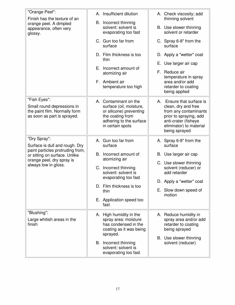
"Orange Peel":
Finish has the texture of anorange peel. A dimpledappearance, often veryglossy.
A. Insufficient dilution
B. Incorrect thinningsolvent: solvent isevaporating too fast
C. Gun too far fromsurface
D. Film thickness is toothin
E. Incorrect amount ofatomizing air
F. Ambient airtemperature too high
A. Check viscosity; addthinning solvent
B. Use slower thinningsolvent or retarder
C. Spray 6-8" from thesurface
D. Apply a "wetter" coat
E. Use larger air cap
F. Reduce airtemperature in sprayarea and/or addretarder to coatingbeing applied
"Fish Eyes":
Small round depressions inthe paint film. Normally formas soon as part is sprayed.
A. Contaminant on thesurface (oil, moisture,or silicone) preventingthe coating fromadhering to the surfacein certain spots
A. Ensure that surface isclean, dry and freefrom any contaminantsprior to spraying, addanti-crater (fisheyeeliminator) to materialbeing sprayed
"Dry Spray":
Surface is dull and rough. Drypaint particles protruding from,or sitting on surface. Unlikeorange peel, dry spray isalways low in gloss.
A. Gun too far fromsurface
B. Incorrect amount ofatomizing air
C. Incorrect thinningsolvent: solvent isevaporating too fast
D. Film thickness is toothin
E. Application speed toofast
A. Spray 6-8" from thesurface
B. Use larger air cap
C. Use slower thinningsolvent (reducer) oradd retarder
D. Apply a "wetter" coat
E. Slow down speed ofmotion
"Blushing":
Large whitish areas in thefinish
A. High humidity in thespray area: moisturehas condensed in thecoating as it was beingsprayed.
B. Incorrect thinningsolvent: solvent isevaporating too fast
A. Reduce humidity inspray area and/or addretarder to coatingbeing sprayed
B. Use slower thinningsolvent (reducer)

18
OPTIONS AND ACCESSORIES
CUP-FED SYSTEMS
Cup-fed systems include a turbine, air hose and cup-fed spray gun. The guns with these systems are supplied with a1 Qt/L paint cup and are ideal for spraying applications where versatility and portability are essential.
NEEDLES, NOZZLES AND AIR CAPS
The proper needle, nozzle and air cap combination is critical to the optimal performance of any spraying system.Needles and nozzles are sized together – when changing the needle, the nozzle must be changed as well. Air capsare sized separately and can be changed without necessarily changing the needle and nozzle.
Turbine Products Inc. manufactures five different sizes of needles/nozzles/air caps ranging from 1.0mm – 2.0mm.For more information about needles, nozzles, and air caps, and how to select the proper combination for yourapplication, refer to pages 5 and 6 of this manual.
ACCESSORIES
Remote Cup Assembly
For maximum portability and control, and to keep the weight of the paint cup off of your wrist, a 40” remote cupassembly is available. This will allow you to operate the Sprayfine gun in any orientation, including upside-down.
2 Qt/L Paint Cup
When the 1Qt/L cup on the cup-fed gun is too small, a remote 2 Qt/L cup can be installed on any Sprayfine gun.The 2 Qt/L cup can be pressurized by the turbine or by a compressor – the possibility of pressurizing with the turbineis dependent on the coating being sprayed. Remote 2 Qt/L cups are supplied with a gun conversion kit.
REPLACEMENT PARTS AND TECHNICAL SPECIFICATIONS
For up-to-date parts breakdowns of any Sprayfine product and/or technical specifications other than those listed inSprayfine’s literature, please contact Turbine Products Inc. directly – we will be pleased to assist you.

19
WARRANTY INFORMATION
LIMITED WARRANTY
Turbine Products Inc. warrants to the original purchaser that the Sprayfine equipment described in this manual willbe free of defects in materials and workmanship for a period of TWO (2) YEARS from the date of purchase asoutlined by the Turbine Products Inc. warranty. Turbine Products Inc.'s only obligation shall be to repair or replace, atTurbine products Inc.’s option, such product proved to be defective during the warranty period.
To take advantage of this warranty, the product or part must be returned to us with transportation charges prepaid.Proof of purchase date and an explanation of the complaint must accompany the merchandise. If our inspectionverifies the defect, we will either repair or replace the product at our election or we may elect to refund the purchaseprice if we cannot readily and quickly provide you with a replacement. We will return repaired products at ourexpense, but if we determine there is no defect, or that the defect resulted from causes not within the scope of ourwarranty, then you must bear the cost of returning the product.
All statements, technical information and recommendations enclosed are based upon tests that Turbine ProductsInc. considers reliable. However, neither the seller nor the manufacturer shall be liable for any injury, loss or damage,direct or consequential, arising from the use of the product or the inability to use the product. Before use, users shalldetermine the suitability of the product for his/her intended use. The user assumes all risk and liability whatsoever inthe use or failure to use the product, whether due to a product defect or not. Turbine Products Inc.'s only obligationshall be to replace or repair, at its option, the quantity of product proved to be defective and any consequentialdamages shall be limited to the value of the Sprayfine equipment purchased.
For further information, please contact Turbine Products Inc. directly at:
USA
509 Norwich Ave, Suite L-5
Taftville CT 06380
860-204-9021
www.turbineproducts.com