splx 12 - soundstream | mobile car audio/video, marine ... subwoof.pdfparallel wiring of dual voice...
TRANSCRIPT

Parallel Wiring of Dual Voice Coils (1 Woofer)
Parallel Wiring of Dual Voice Coils (2 Woofers)
Series Wiring of Dual Voice Coils (1 Woofer)
Series/Parallel Wiring of Dual Voice Coils (2 Woofers)
Owner's manual
REV 011106JMH
SOUNDSTREAM SPLX Woofer
Thiele / Small Parameters SPLX-122
Design FeaturesCast Aluminum BasketKevlar/Paper Mix ConeUV Coated Foam Surround1-Piece Rubber GasketGold Plated Push Terminals
Building the Enclosure
Recommended wiring
Optimum
Minimum
1 cubic foot
.75 cubic feet
Recommended box sizesSealed Enclosure Recommendations
Vented Enclosure Recommendations
SPLX 12
RMS Power (Watts)
VOICE COIL DIAMETER (INCHES)
VOICE COIL IMPEDANCE (INCHES)
WOOFER DISPLACEMENT (FT3)
MAGNET WEIGHT (oz)
FREQUENCY RESPONSE (Hz)
Fs (Hz)
Qes
Qms
Qts
Vas (Ft3)
Xmax (in.)
SPL (dB)
HOLE SIZE (INCHES)
WOOFER DEPTH (INCHES)
750
3
DUAL 2 Ohm
0.1
192
25-300
35
0.342
5.387
0.322
1.42
0.565
89
11.25
7.25
If you are an enthusiast that plays your system loud and hard, the SPLXWoofers will take you to the next level. Capable of working in small enclosures for audiophiles and large vented for SPLX Max “Bass Heads”, this is woofer was a great a choice if you are serious about your sound.
We ask that you take a moment to read through the entire manual before installing the woofer to familiarize your self with the connection procedure as well as determining the best fit enclosure for you and your vehicle’s application.
Congratulations and Thank You for you purchase of an SPLX Woofer. We are confidant you will enjoy the performance of this woofer for many years.
First determine the dimensions of your enclosure. Be certain the box dimensions that you have designed will fit in the locations you have chosen. Sometimes, making a cardboard box with the identical outer dimensions is helpful to confirm it will fit properly. We recommend using .75” thick MDF (Medium Density Fiberboard) to build your speaker box with.
Use a “T-Square” to verify you have cut all your precise right angles before you assemble the box completely. Use high quality wood glue along with nails and screws for proper assembly.
Apply a sealant to all of the inside corners of the enclosure to assure proper sealing of the box.
It is recommended to stuff a sealed enclosure with approximately 50% fill (DACRON or Polyester Insulation) for damping purposes.
Strip off approximately .5”/13mm of wire insulation to assure the bare wire lead penetrates all the way through the push terminal. Follow by using additional sealant around the wire lead exiting the enclosure or around the terminal cup if one is being used.
NOTE: A mathematical reference to determining impedance of multiple coils in one circuit is to DIVIDE the Impedance of the coils by their quantity when connected in Parallel or simply add the impedance in a concurrent matter if you series the coils in a circuit.
The following page explains a few different methods for you to match the impedance of the woofer(s) to the optimum or near best capabili-ties of your amplifier. It is your responsibility to calculate the correct load for your amp. Please take a moment to read through the diagrams to insure maximum performance of your woofers and amplifier(s).
Optimum
Minimum
Port (dia x length) Qty of Port(s)Tune Freq.F3Required Airspace
2 cubic foot
1.5 cubic foot 36Hz
36Hz
33Hz
33Hz
1
3
4" x 12"
4" x 18"
2 ohm LOAD
Amplifier
4 ohm
Woofer
4 ohm
1 ohm LOAD
4 ohm
Woofer
4 ohm 4 ohm
Woofer
4 ohm
Amplifier
4 ohm
Woofer
4 ohm
Amplifier
8 ohm LOAD
4 ohm LOAD
4 ohm
Woofer
4 ohm 4 ohm
Woofer
4 ohm
Amplifier
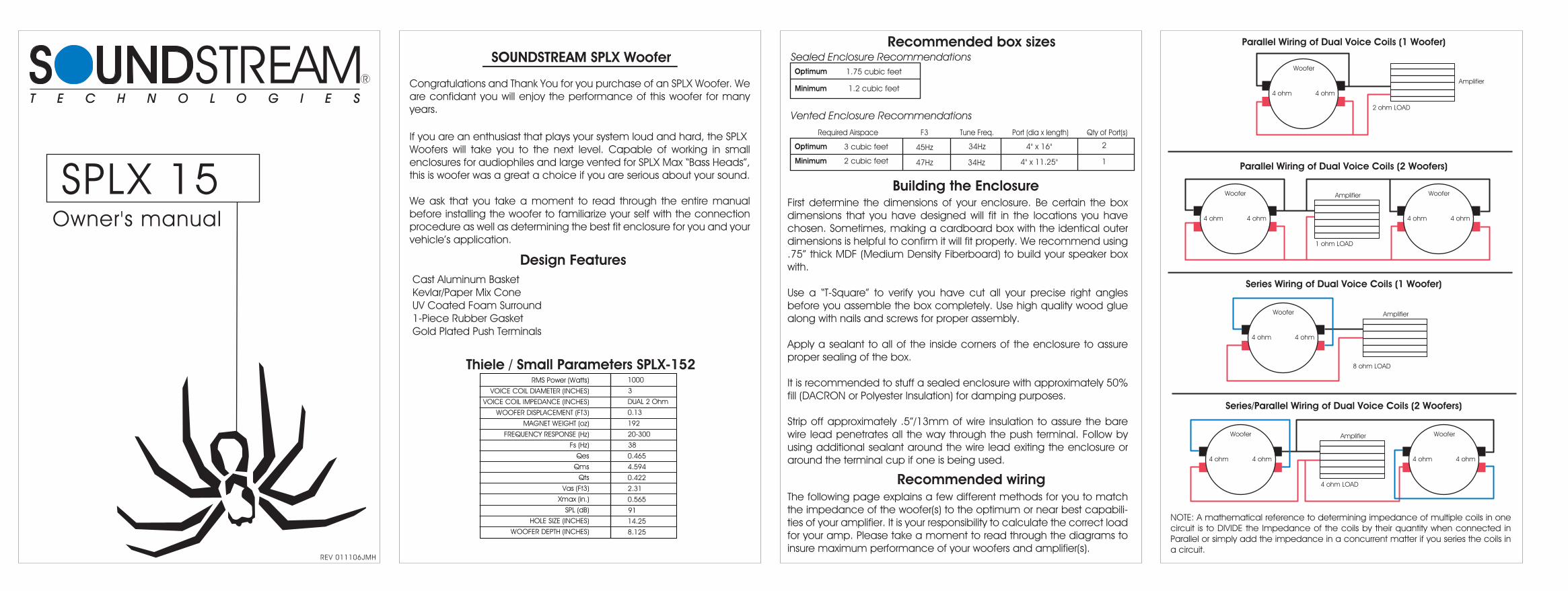
Parallel Wiring of Dual Voice Coils (1 Woofer)
Parallel Wiring of Dual Voice Coils (2 Woofers)
Series Wiring of Dual Voice Coils (1 Woofer)
Series/Parallel Wiring of Dual Voice Coils (2 Woofers)
Owner's manual
REV 011106JMH
SOUNDSTREAM SPLX Woofer
Design FeaturesCast Aluminum BasketKevlar/Paper Mix ConeUV Coated Foam Surround1-Piece Rubber GasketGold Plated Push Terminals
Building the Enclosure
Recommended wiring
Optimum
Minimum
1.75 cubic feet
1.2 cubic feet
Recommended box sizesSealed Enclosure Recommendations
Vented Enclosure Recommendations
SPLX 15
1000
3
DUAL 2 Ohm
0.13
192
20-300
38
0.465
4.594
0.422
2.31
0.565
91
14.25
8.125
Thiele / Small Parameters SPLX-152RMS Power (Watts)
VOICE COIL DIAMETER (INCHES)
VOICE COIL IMPEDANCE (INCHES)
WOOFER DISPLACEMENT (FT3)
MAGNET WEIGHT (oz)
FREQUENCY RESPONSE (Hz)
Fs (Hz)
Qes
Qms
Qts
Vas (Ft3)
Xmax (in.)
SPL (dB)
HOLE SIZE (INCHES)
WOOFER DEPTH (INCHES)
If you are an enthusiast that plays your system loud and hard, the SPLXWoofers will take you to the next level. Capable of working in small enclosures for audiophiles and large vented for SPLX Max “Bass Heads”, this is woofer was a great a choice if you are serious about your sound.
We ask that you take a moment to read through the entire manual before installing the woofer to familiarize your self with the connection procedure as well as determining the best fit enclosure for you and your vehicle’s application.
Congratulations and Thank You for you purchase of an SPLX Woofer. We are confidant you will enjoy the performance of this woofer for many years.
First determine the dimensions of your enclosure. Be certain the box dimensions that you have designed will fit in the locations you have chosen. Sometimes, making a cardboard box with the identical outer dimensions is helpful to confirm it will fit properly. We recommend using .75” thick MDF (Medium Density Fiberboard) to build your speaker box with.
Use a “T-Square” to verify you have cut all your precise right angles before you assemble the box completely. Use high quality wood glue along with nails and screws for proper assembly.
Apply a sealant to all of the inside corners of the enclosure to assure proper sealing of the box.
It is recommended to stuff a sealed enclosure with approximately 50% fill (DACRON or Polyester Insulation) for damping purposes.
Strip off approximately .5”/13mm of wire insulation to assure the bare wire lead penetrates all the way through the push terminal. Follow by using additional sealant around the wire lead exiting the enclosure or around the terminal cup if one is being used.
NOTE: A mathematical reference to determining impedance of multiple coils in one circuit is to DIVIDE the Impedance of the coils by their quantity when connected in Parallel or simply add the impedance in a concurrent matter if you series the coils in a circuit.
The following page explains a few different methods for you to match the impedance of the woofer(s) to the optimum or near best capabili-ties of your amplifier. It is your responsibility to calculate the correct load for your amp. Please take a moment to read through the diagrams to insure maximum performance of your woofers and amplifier(s).
Optimum
Minimum
Port (dia x length) Qty of Port(s)Tune Freq.F3Required Airspace
3 cubic feet
2 cubic feet 34Hz
34Hz
47Hz
45Hz
1
2
4" x 11.25"
4" x 16"
2 ohm LOAD
Amplifier
4 ohm
Woofer
4 ohm
1 ohm LOAD
4 ohm
Woofer
4 ohm 4 ohm
Woofer
4 ohm
Amplifier
4 ohm
Woofer
4 ohm
Amplifier
8 ohm LOAD
4 ohm LOAD
4 ohm
Woofer
4 ohm 4 ohm
Woofer
4 ohm
Amplifier

Parallel Wiring of Dual Voice Coils (1 Woofer)
Parallel Wiring of Dual Voice Coils (2 Woofers)
Series Wiring of Dual Voice Coils (1 Woofer)
Series/Parallel Wiring of Dual Voice Coils (2 Woofers)
Owner's manual
REV 011106JMH
SOUNDSTREAM SPLX Woofer
Thiele / Small Parameters SPLX-124
Design FeaturesCast Aluminum BasketKevlar/Paper Mix ConeUV Coated Foam Surround1-Piece Rubber GasketGold Plated Push Terminals
Building the Enclosure
Recommended wiring
Optimum
Minimum
1 cubic foot
.75 cubic feet
Recommended box sizesSealed Enclosure Recommendations
Vented Enclosure Recommendations
SPLX 124
1000
3
QUAD 2 Ohm
.10
192
25-300
29
.294
5.887
.280
1.42
.565
87
11.25
7.25
RMS Power (Watts)
VOICE COIL DIAMETER (INCHES)
VOICE COIL IMPEDANCE (INCHES)
WOOFER DISPLACEMENT (FT3)
MAGNET WEIGHT (oz)
FREQUENCY RESPONSE (Hz)
Fs (Hz)
Qes
Qms
Qts
Vas (Ft3)
Xmax (in.)
SPL (dB)
HOLE SIZE (INCHES)
WOOFER DEPTH (INCHES)
If you are an enthusiast that plays your system loud and hard, the SPLXWoofers will take you to the next level. Capable of working in small enclosures for audiophiles and large vented for SPLX Max “Bass Heads”, this is woofer was a great a choice if you are serious about your sound.
We ask that you take a moment to read through the entire manual before installing the woofer to familiarize your self with the connection procedure as well as determining the best fit enclosure for you and your vehicle’s application.
Congratulations and Thank You for you purchase of an SPLX Woofer. We are confidant you will enjoy the performance of this woofer for many years.
First determine the dimensions of your enclosure. Be certain the box dimensions that you have designed will fit in the locations you have chosen. Sometimes, making a cardboard box with the identical outer dimensions is helpful to confirm it will fit properly. We recommend using .75” thick MDF (Medium Density Fiberboard) to build your speaker box with.
Use a “T-Square” to verify you have cut all your precise right angles before you assemble the box completely. Use high quality wood glue along with nails and screws for proper assembly.
Apply a sealant to all of the inside corners of the enclosure to assure proper sealing of the box.
It is recommended to stuff a sealed enclosure with approximately 50% fill (DACRON or Polyester Insulation) for damping purposes.
Strip off approximately .5”/13mm of wire insulation to assure the bare wire lead penetrates all the way through the push terminal. Follow by using additional sealant around the wire lead exiting the enclosure or around the terminal cup if one is being used.
NOTE: A mathematical reference to determining impedance of multiple coils in one circuit is to DIVIDE the Impedance of the coils by their quantity when connected in Parallel or simply add the impedance in a concurrent matter if you series the coils in a circuit.
The following page explains a few different methods for you to match the impedance of the woofer(s) to the optimum or near best capabili-ties of your amplifier. It is your responsibility to calculate the correct load for your amp. Please take a moment to read through the diagrams to insure maximum performance of your woofers and amplifier(s).
Optimum
Minimum
Port (dia x length) Qty of Port(s)Tune Freq.F3Required Airspace
2 cubic foot
1.5 cubic foot 36Hz
36Hz
33Hz
33Hz
1
3
4" x 12"
4" x 18"
2 ohm LOAD
Amplifier
4 ohm
Woofer
4 ohm
1 ohm LOAD
4 ohm
Woofer
4 ohm 4 ohm
Woofer
4 ohm
Amplifier
4 ohm
Woofer
4 ohm
Amplifier
8 ohm LOAD
4 ohm LOAD
4 ohm
Woofer
4 ohm 4 ohm
Woofer
4 ohm
Amplifier

Parallel Wiring of Dual Voice Coils (1 Woofer)
Parallel Wiring of Dual Voice Coils (2 Woofers)
Series Wiring of Dual Voice Coils (1 Woofer)
Series/Parallel Wiring of Dual Voice Coils (2 Woofers)
Owner's manual
REV 011106JMH
SOUNDSTREAM SPLX Woofer
Design FeaturesCast Aluminum BasketKevlar/Paper Mix ConeUV Coated Foam Surround1-Piece Rubber GasketGold Plated Push Terminals
Building the Enclosure
Recommended wiring
Optimum
Minimum
1.75 cubic feet
1.2 cubic feet
Recommended box sizesSealed Enclosure Recommendations
Vented Enclosure Recommendations
SPLX 154
1000
3
QUAD 2 Ohm
.13
192
20-300
34
.388
5.041
.360
2.31
.565
90
14.25
8.125
Thiele / Small Parameters SPLX-154RMS Power (Watts)
VOICE COIL DIAMETER (INCHES)
VOICE COIL IMPEDANCE (INCHES)
WOOFER DISPLACEMENT (FT3)
MAGNET WEIGHT (oz)
FREQUENCY RESPONSE (Hz)
Fs (Hz)
Qes
Qms
Qts
Vas (Ft3)
Xmax (in.)
SPL (dB)
HOLE SIZE (INCHES)
WOOFER DEPTH (INCHES)
If you are an enthusiast that plays your system loud and hard, the SPLXWoofers will take you to the next level. Capable of working in small enclosures for audiophiles and large vented for SPLX Max “Bass Heads”, this is woofer was a great a choice if you are serious about your sound.
We ask that you take a moment to read through the entire manual before installing the woofer to familiarize your self with the connection procedure as well as determining the best fit enclosure for you and your vehicle’s application.
Congratulations and Thank You for you purchase of an SPLX Woofer. We are confidant you will enjoy the performance of this woofer for many years.
First determine the dimensions of your enclosure. Be certain the box dimensions that you have designed will fit in the locations you have chosen. Sometimes, making a cardboard box with the identical outer dimensions is helpful to confirm it will fit properly. We recommend using .75” thick MDF (Medium Density Fiberboard) to build your speaker box with.
Use a “T-Square” to verify you have cut all your precise right angles before you assemble the box completely. Use high quality wood glue along with nails and screws for proper assembly.
Apply a sealant to all of the inside corners of the enclosure to assure proper sealing of the box.
It is recommended to stuff a sealed enclosure with approximately 50% fill (DACRON or Polyester Insulation) for damping purposes.
Strip off approximately .5”/13mm of wire insulation to assure the bare wire lead penetrates all the way through the push terminal. Follow by using additional sealant around the wire lead exiting the enclosure or around the terminal cup if one is being used.
NOTE: A mathematical reference to determining impedance of multiple coils in one circuit is to DIVIDE the Impedance of the coils by their quantity when connected in Parallel or simply add the impedance in a concurrent matter if you series the coils in a circuit.
The following page explains a few different methods for you to match the impedance of the woofer(s) to the optimum or near best capabili-ties of your amplifier. It is your responsibility to calculate the correct load for your amp. Please take a moment to read through the diagrams to insure maximum performance of your woofers and amplifier(s).
Optimum
Minimum
Port (dia x length) Qty of Port(s)Tune Freq.F3Required Airspace
3 cubic feet
2 cubic feet 34Hz
34Hz
47Hz
45Hz
1
2
4" x 11.25"
4" x 16"
2 ohm LOAD
Amplifier
4 ohm
Woofer
4 ohm
1 ohm LOAD
4 ohm
Woofer
4 ohm 4 ohm
Woofer
4 ohm
Amplifier
4 ohm
Woofer
4 ohm
Amplifier
8 ohm LOAD
4 ohm LOAD
4 ohm
Woofer
4 ohm 4 ohm
Woofer
4 ohm
Amplifier