split “l” series systems 072, 090, 120, 180 & 240...
TRANSCRIPT

Bulletin #210164February 1997
LSA072, 090, 120, 180 & 240 MODELS“C” SERIES CONDENSING UNITS
“P” SERIES HEAT PUMPS
Typical Applications
Rooftop InstallationUnit on a slab at grade level
SPLIT “L” SERIES SYSTEMS
Condensing Units – 6 Thru 20 Ton(21.1 Thru 70.3 kW)
Heat Pumps – 7.5 & 10 Ton(26.4 & 35.2 kW)
LSA072C/LSA090CCondensing Units
LSA120C Condensing UnitsLSA120P Heat Pump Units
LSA180C/LSA240CCondensing Units
LSA090PHeat Pump Units
The maple leaf symbol in this bulletin denotes Canadian only usage where applicableNOTE — Due to Lennox’ ongoing committment to quality, Specifications, Ratings and Dimensions subject to change without notice and without incurring liability.
1997 Lennox Industries Inc.

FEATURES
Applications� Condensing units available in 6, 7.5, 10, 15 and 20 ton
(21.1, 26.4, 35.2, 52.8 and 70.3 kW) nominal sizes.� Heat pump units available in 7.5 and 10 ton (26.4 and 35.2
kW) nominal sizes.� Designed for applications with remotely located blower-coil
unit (condensing and heat pump units) or furnace withadd-on evaporator coil (condensing units only).
� See ARI rating tables for efficiencies and capacities.� For blower coil unit or evaporator unit data, see bulletins
indexed in tab section Coils-Blower Coil Units.� All units shipped factory assembled, piped and wired.� Test operated at factory to ensure dependable operation.
Approvals� All units tested in Lennox Research Laboratory
environmental test room.� LSA072C, LSA090C, LSA120C condensing units rated in
accordance with ARI Standard 210/240-94.� LSA180C, LSA240C condensing units rated in accordance
with ARI Standard 365-87.� LSA090P, LSA120P heat pump units rated in accordance with
ARI Standard 210/240-94.� Sound tested in Lennox reverberant sound test room in
accordance with test conditions included in ARI Standard270-95
� Units and components within are bonded for grounding tomeet safety standards for servicing required by U.L., U.L.C.,N.E.C. and C.E.C.
� All units are U.L. listed and U.L.C. certified.
Equipment Warranty� Compressor – Five years.� All other covered components – One year.� Refer to Lennox Equipment Limited Warranty included
with unit for details.
Compressors� LSA072C features single scroll compressor.
Scroll compressor features:� Compressor features high efficiency with uniform
suction flow, constant discharge flow and high volumetricefficiency and quiet operation.
� Scroll compressor technology eliminates need for startcapacitor and start relay.
� Compressor consists of two involute spiral scrollsmatched together to generate a series of crescent shapedgas pockets between them.
� During compression, one scroll remains stationary whilethe other scroll orbits around it.
� Gas is drawn into the outer pocket, the pocket is sealed asthe scroll rotates.
� As the spiral movement continues, gas pockets are pushedto the center of the scrolls. Volume between the pockets issimultaneously reduced.
� When pocket reaches the center, gas is now at highpressure and is forced out of a port located in the centerof the fixed scrolls.
� During compression, several pockets are compressedsimultaneously resulting in a smooth continuouscompression cycle.
� Continuous flank contact, maintained by centrifugal force,minimizes gas leakage and maximizes efficiency.
� Scroll compressor is tolerant to the effects of slugging andcontaminants. If this occurs, scrolls separate, allowingliquid or contaminants to to be worked toward the centerand discharged.
� Low gas pulses during compression reduces operationalsound levels.
� Compressor motor is internally protected from excessivecurrent and temperature.
� Compressor is installed in the unit on resilient rubbermounts for vibration free operation.
Compressors – continued� LSA090C, LSA120C, LSA090P, LSA120P, have single
reciprocating compressor.� LSA180C, LSA240C have two reciprocating compressors.
Reciprocating compressor features:� Hermetically sealed steel shell.� Cast iron compressor housing for long life.� Internal overload protection assures protection from
excessive current and temperature. Automatic reset.� Aluminum pistons and connecting rods.� Ringed valves.� Stainless steel discharge valves.� Large internal muffler for quiet operation.� Patented internal spring mounting for vibration free
operation.� Compressor installed in unit on resilient rubber mounts
for quiet, vibration free operation.
Crankcase Heater (All Models)� Assures proper compressor lubrication at all times.
Cabinet� Heavy gauge steel cabinet with five station metal wash
process.� Pre–painted panels provides superior rust and corrosion
protection.� Removeable panels allow access for unit servicing. See
dimension drawings.� Heavy duty steel base channels raise the unit off of
mounting surface away from damaging moisture.� Unit lifting holes and forklift slots furnished in base rails.
See dimension drawings.
Control Box� Control box located in separate compartment in unit
cabinet (072, 090, 120 models).� Hinged panel with quarter turn fastener for easy access.� Slide out control box allows easy access to controls (180,
240 models).� All controls are pre-wired at the factory.
Copper Tube/Enhanced Fin Coil(s)� LSA072C equipped with single “L” shaped coil.� LSA090C, LSA090P equipped with single “U” shaped coil.� LSA120, LSA120P equipped with two slab coils.� LSA180C, LSA240C equipped with four slab coils.� Lennox designed and fabricated coils constructed of
precisely spaced ripple-edge aluminum fins machinefitted to seamless copper tubes.
� Lanced fins provide maximum exposure of fin surface toair stream resulting in excellent heat transfer.
� Fins equipped with collars that grip tubing for maximumcontact area.
� Flared shoulder tubing connections and silver solderingprovide tight, leakproof joints.
� Long life copper tubing is corrosion-resistant and easy tofield service.
� Thoroughly factory tested under high pressure to insureleakproof construction.
� Completely accessible for cleaning.
Coil Guard� Corrosion resistant PVC (polyvinyl chloride) coated steel
wire guard(s) furnished as standard.
LSA Split Systems 090–240 / Page 2 �

FEATURES – continued
Outdoor Fan(s)� LSA072C, LSA090C, LSA090P units have one outdoor fan.� LSA120C, LSA120P units have two outdoor fans.� LSA180C, LSA240C units have four outdoor fans.� Direct drive fan(s) moves large volumes of air uniformly
through entire condenser coil(s) for high refrigerantcooling capacity.
� Upward discharge of air reduces operating sound levelsand prevents damage to lawns, shrubs and walkways.
� Fan motors are totally enclosed, inherently protected andequipped with a rain shield.
� Fan service access is accomplished by removal of fanguards.
Minimum Run Time Control (Condensing Units)� Prevents compressor short cycling and allows time for
suction and discharge pressures to equalize and assuresoil return to compressor.
� 5 minute minimum run time regardless of cooling demand.
Defrost Control/Timed–Off Control (Heat Pump Units)� Solid-state time/temperature defrost control is furnished as
standard equipment.� Control initiates a defrost cycle every 30, 60 or 90 minutes
of compressor “on” time at outdoor temperatures below35� F (2�C) (factory setting 60 minutes).
� Maximum defrost cycle 14 minutes.� Defrost thermostat mounted on liquid line determines
when defrost cycle is required.� Pressure switch mounted on discharge line determines
when defrost cycle is terminated.� Timed off function prevents compressor short cycling.� Provides 5 minute delay between compressor shutoff and
start–up.� Allows suction and discharge pressure to equalize,
permitting compressor to start in unloaded condition.� Automatic reset.� Connections for ambient compensating thermistor and
service light thermostat.
Reversing Valve (Heat Pump Units)� Factory installed 4–way reversing valve provides rapid
change in refrigerant flow direction resulting in quickchangeover from cooling to heating and vice–versa.
� Valve operates on pressure differential between outdoorunit and indoor unit.
Refrigerant Lines and Service Valves� Sweat connections.� Fully serviceable brass service valves prevent corrosion
and provide complete service access to refrigerantsystem. Suction valve can be fully shut off, while liquidvalve can be front seated to manage refrigerant chargewhile servicing system.
� Thermometer well is provided for checking refrigerantcharge. Refrigerant lines and field wiring inlets are locatedin one central area of the unit cabinet.
Hi-Capacity Drier� Furnished for field installation. Drier traps any moisture or
dirt that could contaminate the refrigerant system.
High Pressure Switch� Shuts off unit if abnormal operating conditions cause
discharge pressure to rise above setting.� Protects the compressor from excessive condensing
pressure.� Manual reset.
Low Pressure Switch� Shuts off unit if suction pressure falls below setting.� Provides loss of charge and freeze-up protection.� Automatic reset.
Low Ambient Operation� Units will operate satisfactorily down to 0�F (–17.7�C)
outdoor air temperature without any additional controls.
OPTIONS (Must be Ordered Extra)
Thermostat (Optional)� Thermostat is not furnished with unit and must be ordered
extra.� See Thermostats bulletin and Lennox Price Book.
Hail Guard Protection (Optional)� Heavy duty field installed coil guard protects coils
from damage.� LSA072C uses (83K36).� LSA090C, LSA090P use (83K37).� LSA120C, LSA120P, LSA180C, LSA240C use (79K91).
Hot Gas Bypass (Factory or Field Installed)� Available for LSA072C, LSA090C, LSA120C only.� Factory or field installed kit (79K90) contains hot gas
bypass valve and superheat valve for reduced capacitycontrol of condensing units.
Corrosion Protection (Factory Installed)� Phenolic epoxy coating applied to condenser coils and
base section.
Disconnect Switch (Factory Installed)� Accessible from outside of unit.� Spring loaded weatherproof cover.
Service Outlets(2) (Factory Installed)� 115v ground fault circuit interrupter (GFCI) type.� Field wired.
LSA Split Systems 090–240 / Page 3 �

SPECIFICATIONS CONDENSING UNITS
Model No. LSA072C LSA090C LSA120C LSA180C LSA240C
Nominal Size – Tons (kW) 6 (21.1) 7.5 (26.4) 10 (35.2) 15 (52.8) 20 (70.3)
Net face area —Outer coil 12.92 (1.20) 16.35 (1.52) 29.36 (2.73) total 58.68 (5.45) total
Condensersq. ft. (m2) Inner coil 12.59 (1.17) 15.70 (1.46) – – – –
Coil Tube diameter — in. (mm) & no. of rows 3/8 (9.5) – 2 3/8 (9.5) – 1 3/8 (9.5) – 2
Fins per inch (m) 20 (787) 15 (630) 20 (787) 15 (630)
Diameter — in. (mm) & no. of blades (1) 24 (610) – 4 (2) 24 (610) – 3 (4) 24 (610) – 3
Motor hp (W) (1) 1/2 (373) (2) 1/3 (249) (4) 1/3 (249)
CondenserFans Cfm (L/s) total air volume 4500 (2125) 4800 (2265) 8200 (3870) 16,000 (7550)
Rpm 1060 1100 1075
Watts 620 610 740 total 1400 total
Refrigerant charge dry air
Liquid line (o.d.) — in. (mm) connection (sweat) 5/8 (15.9) (2) 5/8 (15.9)
Suction line (o.d.) — in. (mm) connection (sweat) 1–1/8 (28.6) 1–3/8 (34.9) (2) 1–3/8 (34.9)
Shipping weight — lbs. (kg) 1 package 354 (161) 427 (193) 555 (251) 968 (439) 1096 (497)
ELECTRICAL DATA CONDENSING UNITS
Model No. LSA072C LSA090C LSA120C
Line voltage data — 60 hz 208/230v3ph
460v3ph
575v3ph
208/230v3ph
460v3ph
575v3ph
208/230v3ph
460v3ph
575v3ph
Compressors (1)Rated load amps 18.6 9 7.4 24.7 10.4 8.1 34.4 13.9 11.1
Compressors (1)Locked rotor amps 156 70 54 164 79 63 195 98 78
Condenser CoilFan Motor
Full load amps (total) 3 1.5 1.2 3 1.5 1.2 2.4 (4.8) 1.3 (2.6) 1 (2)Fan Motor(1 phase) Locked rotor amps (total) 6 3 2.9 6 3 2.9 4.7 (9.4) 2.4 (4.8) 1.9 (3.8)
Recommended maximum fuse or�circuit breaker size (amps) 40 20 15 50 20 15 80 30 25
�Minimum circuit ampacity 27 13 11 34 15 12 48 20 16
�Refer to National or Canadian Electrical Code manual to determine wire, fuse and disconnect size requirements.NOTE — Extremes of operating range are plus and minus 10% of line voltage.�HACR type (under 100 amps). U.S. only.
ELECTRICAL DATA CONDENSING UNITS
Model No. LSA180C LSA240C
Line voltage data — 60 hz 208/230v3ph
460v3ph
575v3ph
208/230v3ph
460v3ph
575v3ph
Compressors (2)Rated load amps – each (total) 24.7 (49.4) 10.4 (20.8) 8.1 (16.2) 34.4 (68.8) 13.9 (27.8) 11.1 (22.2)
Compressors (2)Locked rotor amps – each (total) 164 (328) 79 (158) 63 (126) 195 (390) 98 (196) 78 (156)
Condenser CoilFan Motor
Full load amps – each (total) 2.4 (9.6) 1.3 (5.2) 1 (4) 2.4 (9.6) 1.3 (5.2) 1 (4)Fan Motor(1 phase) Locked rotor amps – each (total) 4.7 (18.8) 2.4 (9.6) 1.9 (7.6) 4.7 (18.8) 2.4 (9.6) 1.9 (7.6)
Recommended maximum fuse or�circuit breaker size (amps) 80 35 30 110 50 40
�Minimum circuit ampacity 66 29 23 87 37 29
�Refer to National or Canadian Electrical Code manual to determine wire, fuse and disconnect size requirements.NOTE — Extremes of operating range are plus and minus 10% of line voltage.�HACR type (under 100 amps). U.S. only.
LSA Split Systems 090–240 / Page 4 �

SPECIFICATIONS HEAT PUMPS
Model No. LSA090P LSA120P
Nominal Size – Tons (kW) 7.5 (26.4) 10 (35.2)
Net face area —Outer coil 21.80 (2.03) 29.34 (2.73)
Outdoor
Net face area sq. ft. (m2)
Inner coil 20.94 (1.95) – – – –Outdoor
CoilTube diameter — in. (mm) & no. of rows 3/8 (9.5) – 2
Fins per inch (m) 20 (787)
Diameter — in. (mm) & no. of blades (1) 24 (610) – 4 (2) 24 (610) – 3
Motor hp (W) (1) 1/2 (373) (2) 1/3 (249)
OutdoorCoil
Fan(s)Cfm (L/s) total air volume 5300 (2500) 8200 (3870)
( )
Rpm 1075 1100
Watts 600 740
Refrigerant charge dry air
Liquid line (o.d.) — in. (mm) connection (sweat) 5/8 (15.9)
Vapor line (o.d.) — in. (mm) connection (sweat) 1–3/8 (34.9)
Shipping weight — lbs. (kg) 1 package 490 (222) 604 (274)
ELECTRICAL DATA HEAT PUMPS
Model No. LSA090P LSA120P
Line voltage data — 60 hz 208/230v3ph
460v3ph
575v3ph
208/230v3ph
460v3ph
575v3ph
Compressor (1)
Rated load amps 24.7 10.4 8.1 34.4 13.9 11.1
Compressor (1)
Locked rotor amps 164 79 63 195 98 78
Condenser CoilFan Motor
Full load amps (total) 3 1.5 1.2 2.4 (4.8) 1.3 (2.6) 1 (2)
Fan Motor(1 phase)
Locked rotor amps (total) 6 3 2.9 4.7 (9.4) 2.4 (4.8) 1.9 (3.8)
Rec. max. fuse or �circuit breaker size (amps) 50 20 15 80 30 25
�Minimum circuit ampacity 34 15 17 48 20 16
�Refer to National or Canadian Electrical Code manual to determine wire, fuse and disconnect size requirements.NOTE — Extremes of operating range are plus and minus 10% of line voltage.�HACR type (under 100 amps). U.S. only.
LSA Split Systems 090–240 / Page 5 �
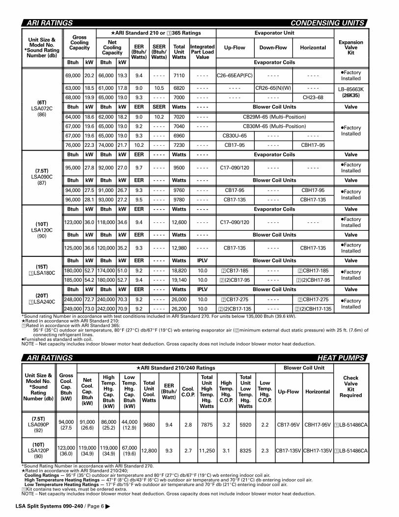
ARI RATINGS CONDENSING UNITS
Gross�ARI Standard 210 or �365 Ratings Evaporator Unit
Unit Size &Model No.
*Sound RatingNumber (db)
GrossCoolingCapacity
NetCoolingCapacity
EER(Btuh/Watts)
SEER(Btuh/Watts)
TotalUnit
Watts
IntegratedPart Load
Value
Up-Flow Down-Flow HorizontalExpansion
ValveKit
Number (db)
Btuh kW Btuh kWWatts) Watts) Watts Value
Evaporator Coils
69,000 20.2 66,000 19.3 9.4 - - - - 7110 - - - - C26–65EAP(FC) - - - - - - - - �FactoryInstalled
63,000 18.5 61,000 17.8 9.0 10.5 6820 - - - - - - - - CR26–65(N)(W) - - - - LB–85663K
(6T)68,000 19.9 65,000 19.0 9.3 - - - - 7000 - - - - - - - - - - - - CH23–68 (26K35)
(6T)
LSA072C Btuh kW Btuh kW EER SEER Watts - - - - Blower Coil Units Valve
(86) 64,000 18.6 62,000 18.2 9.0 10.2 7020 - - - - CB29M–65 (Multi–Position)
67,000 19.6 65,000 19.0 9.2 - - - - 7040 - - - - CB30M–65 (Multi–Position) �Factory
67,000 19.6 65,000 19.0 9.3 - - - - 6960 CB30U–65 - - - - - - - -
yInstalled
76,000 22.3 74,000 21.7 10.2 - - - - 7230 - - - - CB17–95 - - - - CBH17–95
Btuh kW Btuh kW EER - - - - Watts - - - - Evaporator Coils Valve
(7.5T)
LSA090C
95,000 27.8 92,000 27.0 9.7 - - - - 9500 - - - - C17–090/120 - - - - - - - - �FactoryInstalled
LSA090C(87) Btuh kW Btuh kW EER - - - - Watts - - - - Blower Coil Units Valve(87)
94,000 27.5 91,000 26.7 9.3 - - - - 9760 - - - - CB17-95 - - - - CBH17-95 �Factory
96,000 28.1 93,000 27.2 9.5 - - - - 9780 - - - - CB17-135 - - - - CBH17-135
yInstalled
Btuh kW Btuh kW EER - - - - Watts - - - - Evaporator Coils Valve
(10T)
LSA120C
123,000 36.0 118,000 34.6 9.4 - - - - 12,600 - - - - C17–090/120 - - - - - - - - �FactoryInstalled
LSA120C(90) Btuh kW Btuh kW EER - - - - Watts - - - - Blower Coil Units Valve
125,000 36.6 120,000 35.2 9.3 - - - - 12,980 - - - - CB17-135 - - - - CBH17-135 �FactoryInstalled
(15T)
Btuh kW Btuh kW EER - - - - Watts IPLV Blower Coil Units Valve
(15T)
�LSA180C 180,000 52.7 174,000 51.0 9.2 - - - - 18,820 10.0 �CB17-185 - - - - �CBH17-185 �Factory�LSA180C185,000 54.2 180,000 52.7 9.4 - - - - 19,140 10.0 �(2)CB17-95 - - - - �(2)CBH17-95
yInstalled
(20T)
Btuh kW Btuh kW EER - - - - Watts IPLV Blower Coil Units Valve
(20T)
�LSA240C 248,000 72.7 240,000 70.3 9.2 - - - - 26,000 10.0 �CB17-275 - - - - �CBH17-275 �Factory�LSA240C249,000 73.0 242,000 70.9 9.2 - - - - 26,200 10.0 �(2)CB17-135 - - - - �(2)CBH17-135
yInstalled
*Sound rating Number in accordance with test conditions included in ARI Standard 270. For units below 135,000 Btuh (39.6 kW).�Rated in accordance with ARI Standard 210:�Rated in accordance with ARI Standard 365:
95�F (35�C) outdoor air temperature, 80�F (27�C) db/67�F (19�C) wb entering evaporator air (�minimum external duct static pressure) with 25 ft. (7.6m) ofconnecting refrigerant lines.
�Furnished as standard with coil.NOTE – Net capacity includes indoor blower motor heat deduction. Gross capacity does not include indoor blower motor heat deduction.
ARI RATINGS HEAT PUMPS
�ARI Standard 210/240 Ratings Blower Coil Unit
Unit Size &Model No.
*SoundRating
Number (db)
GrossCool.Cap.Btuh(kW)
NetCool.Cap.Btuh(kW)
HighTemp.Htg.Cap.Btuh(kW)
LowTemp.Htg.Cap.Btuh(kW)
TotalUnitCool.Watts
EER(Btuh/Watt)
Cool.C.O.P.
TotalUnitHigh
Temp.Htg.
Watts
HighTemp.Htg.
C.O.P.
TotalUnitLow
Temp.Htg.
Watts
LowTemp.Htg.
C.O.P.
Up-Flow Horizontal
CheckValve
KitRequired
(7.5T)LSA090P
(92)
94,000(27.5
91,000(26.6)
86,000(25.2)
44,000(12.9) 9680 9.4 2.8 7875 3.2 5920 2.2 CB17-95V CBH17-95V �LB-51486CA
(10T)LSA120P
(90)
123,000(36.0)
119,000(34.9)
119,000(34.9)
67,000(19.6) 12,800 9.3 2.7 11,250 3.1 8325 2.3 CB17-135V CBH17-135V �LB-51486CA
*Sound Rating Number in accordance with ARI Standard 270.�Rated in accordance with ARI Standard 210/240;
Cooling Ratings — 95�F (35�C) outdoor air temperature and 80�F (27�C) db/67�F (19�C) wb entering indoor coil air.High Temperature Heating Ratings — 47�F (8�C) db/43�F (6�C) wb outdoor air temperature and 70�F (21�C) db entering indoor coil air.Low Temperature Heating Ratings — 17�F db/15�F wb outdoor air temperature and 70�F db (21�C) entering indoor coil air.
�Kit contains two valves, must be ordered extra.NOTE – Net capacity includes indoor blower motor heat deduction. Gross capacity does not include indoor blower motor heat deduction.
LSA Split Systems 090–240 / Page 6 �

FIELD WIRING — Basic Unit CONDENSING UNITS
DISCONNECTSWITCH
(Optional)(Factory or
Field Installed)
A — Three Wire Power (not furnished)
B — Three Wire Power (not furnished) — See Electrical Data
C — Two Wire Low Voltage (not furnished) — 18 ga. minimum
D — Four Wire Low Voltage (not furnished) — 18 ga. minimum
E — Two Wire Power (115 volt)
All wiring must conform to NEC or CEC and local electrical codes.
B
LENNOXCONDENSING
UNITLENNOX
HEATING UNITOR
*BLOWER COILEVAPORATOR
UNIT
DISCONNECTSWITCH
(By Others)
THERMOSTAT(Optional)
C
D
A
*CB17/CBH17 applications without electric heat require aseparate 70VA (minimum rating) transformer.
115 VOLTSERVICEOUTLET
E
GUIDE SPECIFICATIONS CONDENSING UNITS
Prepared for the guidance of architects, consulting engineers
and mechanical contractors.
General — Furnish and install an air cooled condensing unit.The unit shall be shipped completely factory assembled, pipedand wired internally ready for field connections. In addition,manufacturer shall test operate unit at the factory before ship-ment. The condensing unit shall be a standard product of afirm regularly engaged in the manufacture of heating-coolingequipment. The manufacturer shall have parts and serviceavailable throughout the United States and Canada.
The installed weight shall not be more than . . . . . . . . lbs. (kg).Entire unit shall have a width of not more than . . . . . . . . in-ches (mm), a depth of not more than . . . . . . . . inches (mm)and an overall height of not more than . . . . . . . . inches (mm).
Approvals — All wiring shall be in compliance with NEC or CEC.Shall be rated in accordance with ARI Standard 210/240-94 or365-87. All models shall have U.L. listing and be U.L.C. certified.
Equipment Warranty — The compressor shall have a limitedwarranty for five years. All other covered components shallhave a limited warranty for one year. Refer to Lennox Equip-ment Limited Warranty Certificate furnished with unit for details.
Cooling Capacity — The total cooling capacity shall be. . . . . . . . Btuh (kW) at . . . . . . . . �F (C�) evaporating tempera-ture and outdoor air temperature of . . . . . . . . �F (C�). Thecompressor power input shall not exceed . . . . . . . . kw at theabove conditions. All models shall have low ambient opera-tion down to 0�F (–17.7�C).
Compressor — LSA072C shall have single speed scroll com-pressor. LSA090C, LSA120C shall have single speed recipro-cating compressor. LSA180C, LSA240C shall have two singlespeed reciprocating compressors. Compressors shall be re-siliently mounted, suction cooled, overload protected, andhave internal excessive current and temperature protection.All compressors shall have crankcase heater.
Refrigerant System — Shall include fully serviceable liquidand suction line service valves, gauge ports, hi-capacity drier(field installed), thermometer well, high pressure switch, lowpressure switch and timed-off control. Control options avail-able shall include thermostat.
Condenser Coil(s) — Coil(s) shall be non-ferrous constructionwith aluminum enhanced fins mechanically bonded to dura-ble rifled copper tubes. Coil(s) shall be pressure leak tested.Coil face area shall be not less than . . . . . . . . sq. ft. (m2) Coil(s)shall be protected with steel guard(s).
Cabinet — Shall be constructed of galvanized steel which hasbeen through a metal wash preparation and have a pre–painted finish. Openings shall be provided for refrigerantlines and power connection entry.
Air Mover — Shall be direct drive propeller type fan(s). Mo-tor(s) shall have inherent protection devices and shall be pro-tected from moisture. Motor(s) shall be . . . . . . . . hp (W) withnot more than . . . . . . . . watts input. Fan(s) shall be protectedwith steel guard(s).
OPTIONS
Corrosion Protection – Furnish and factory apply phenolicepoxy coating to condenser coils and base section.
Disconnect Switch – Furnish and factory install unit discon-nect switch. Shall have spring loaded weatherproof cover.
Service Outlets – Furnish and factory install dual 115v groundfault circuit interrupter (GFCI) type. Shall have spring loadedweatherproof cover. Power wiring shall be field provided.
Hail Guard Protection – Furnish and field install heavy dutycoil guard to protect coils.
LSA Split Systems 090–240 / Page 7 �

FIELD WIRING — Basic Unit HEAT PUMPS
A – Three Wire Power (see Electrical Data)
B – Three Wire Power (size to heater capacity)
C – Three Wire Power (size to indoor coil blower motor)
D – Two Wire Low Voltage – 18 ga. minimum
E – Seven Wire Low Voltage – 18 ga. minimum – with Electric Heat
– Nine Wire Low Voltage with Optional Outdoor Thermostat
F – Four Wire Low Voltage – 18 ga. minimum
G– Two Wire Power (115 volt)
– Field Wiring Not Furnished –
All wiring must conform to NEC or CEC and local electrical codes.
E
THERMOSTAT(Optional)
DISCONNECTSWITCH
(Optional)(Factory or
Field Installed)
A
LENNOXOUTDOOR
UNIT
LENNOXINDOOR UNIT
F
F
DISCONNECTSWITCH
(By Others)
DISCONNECTSWITCH
(By Others)
C
B
D
LENNOXOPTIONAL
SUPPLEMENTALELECTRIC
HEAT
OPTIONALOUTDOOR
THERMOSTAT
115 VOLTSERVICEOUTLET
G
GUIDE SPECIFICATIONS HEAT PUMPS
Prepared for the guidance of architects, consulting engineers
and mechanical contractors.
General — Furnish and install an air cooled heat pump outdoorunit. The unit shall be shipped completely factory assembled,piped and wired internally ready for field connections. In addi-tion, manufacturer shall test operate unit at the factory beforeshipment. The outdoor unit shall be a standard product of a firmregularly engaged in the manufacture of heating-cooling equip-ment. The manufacturer shall have parts and service availablethroughout the United States and Canada.
The installed weight shall not be more than . . . . . . . . lbs. (kg).Entire unit shall have a width of not more than . . . . . . . . in-ches (mm), a depth of not more than . . . . . . . . inches (mm)and an overall height of not more than . . . . . . . . inches (mm).
Approvals — All wiring shall be in compliance with NEC andCEC. Shall be rated in accordance with ARI Standard210/240-94. All models shall have U.L. listing and be U.L.C. cer-tified.
Equipment Warranty — The compressor shall have a limitedwarranty for five years. All other covered components shallhave a limited warranty for one year. Refer to Lennox Equip-ment Limited Warranty Certificate furnished with unit for details.
Cooling Capacity — The total cooling capacity shall be. . . . . . . . Btuh (kW) at . . . . . . . . �F (�C) evaporating tempera-ture and outdoor air temperature of . . . . . . . . �F (�C). Thecompressor power input shall not exceed . . . . . . . . kw at theabove conditions. All models shall have low ambient coolingoperation down to 0�F (–17.7�C).
Heating Capacity — The total certified heating capacity shallbe . . . . . . . . Btuh (kW) at . . . . . . . . �F (�C) condensing temper-ature and . . . . . . . . �F (�C) outdoor air temperature. The com-pressor watts input shall not be more than . . . . . . . . watts atthe above conditions.
Outdoor Coil(s) — Coil(s) shall be non-ferrous constructionwith aluminum enhanced fins mechanically bonded to rifledcopper tubes. Coil(s) shall be pressure leak tested. Coil facearea shall be not less than . . . . . . . . sq. ft. (m2) Coil(s) shall beprotected with steel guard(s).
Compressor — LSA090P, LSA120P shall have single speed re-ciprocating compressor. Compressor shall be resilientlymounted, suction cooled, overload protected, and have internalexcessive current and temperature protection. Compressorshall have crankcase heater.
Refrigerant System — Shall include fully serviceable liquidand vapor line service valves, gauge ports, hi-capacity driers,thermometer well, high pressure switch, low pressureswitch, suction line accumulator, expansion valve, reversingvalve and defrost/timed–off control. Control options avail-able shall include thermostat and outdoor thermostat.
Cabinet — Shall be constructed of galvanized steel which hasbeen through a metal wash preparation and have a pre–painted finish. Openings shall be provided for refrigerantlines and power connection entry.
Air Mover — Shall be direct drive blade type fan(s). Motor(s)shall have inherent protection devices and shall be protectedfrom moisture. Motor(s) shall be . . . . . . . . hp (W) with notmore than . . . . . . . . watts input. Fan(s) shall be protected withsteel guard(s).
OPTIONS
Corrosion Protection – Furnish and factory apply phenolicepoxy coating to outdoor coils and base section.
Disconnect Switch – Furnish and factory install unit discon-nect switch. Shall have spring loaded weatherproof cover.
Service Outlets – Furnish and factory install dual 115v groundfault circuit interrupter (GFCI) type. Shall have spring loadedweatherproof cover. Power wiring shall be field provided.
Hail Guard Protection – Furnish and field install heavy dutycoil guard to protect coils.
LSA Split Systems 090–240 / Page 8 �
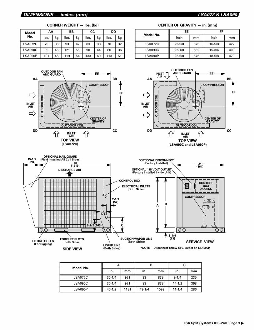
DIMENSIONS — inches (mm) LSA072 & LSA090
CORNER WEIGHT — lbs. (kg)
Model AA BB CC DD
No. lbs. kg lbs. kg lbs. kg lbs. kg
LSA072C 79 36 93 42 83 38 70 32
LSA090C 99 45 121 55 98 44 80 36
LSA090P 101 46 119 54 133 60 113 51
CENTER OF GRAVITY — in. (mm)
Model NoEE FF
Model No.inch mm inch mm
LSA072C 22-5/8 575 16-5/8 422
LSA090C 22-1/8 562 15-3/4 400
LSA090P 22-5/8 575 18-5/8 473
OUTDOOR COIL
TOP VIEW(LSA072C)
SERVICE VIEW
OUTDOOR FANAND GUARD
OUTDOOR COIL
TOP VIEW(LSA090C and LSA090P)
OU
TD
OO
R C
OIL
OUTDOOR FANAND GUARD
COMPRESSOR
OU
TD
OO
R C
OIL
COMPRESSOR
INLETAIR
INLETAIR
INLETAIR
INLETAIR
INLETAIR
AA BB
CCDD
CENTER OFGRAVITY
EE
FF
AA BB
CCDD
CENTER OFGRAVITY
EE
FF
COMPRESSOR
A
3-1/4(83)
34(864)
B
CONTROLBOX
ACCESS
*OPTIONAL DISCONNECT(Factory Installed)
OPTIONAL 115 VOLT OUTLET(Factory Installed Inside Unit)
*NOTE— Disconnect below GFCI outlet on LSA090P.SIDE VIEW
LIFTING HOLES(For Rigging)
FORKLIFT SLOTS(Both Sides)
ELECTRICAL INLETS(Both Sides)
SUCTION/VAPOR LINE(Both Sides)
LIQUID LINE(Both Sides)
2-1/4(57)
48(1219)
3(76)
6-1/2 (165)
DISCHARGE AIR
CONTROL BOX
C
15-1/2(394)
OPTIONAL HAIL GUARD(Field Installed All Coil Sides)
Model NoA B C
Model No.in. mm in. mm in. mm
LSA072C 36-1/4 921 33 838 9-1/4 235
LSA090C 36-1/4 921 33 838 14-1/2 368
LSA090P 46-1/2 1181 43-1/4 1099 11-1/4 286
LSA Split Systems 090–240 / Page 9 �

DIMENSIONS — inches (mm) LSA120
CORNER WEIGHT — lbs. (kg)
Model AA BB CC DD
No. lbs. kg lbs. kg lbs. kg lbs. kg
LSA120C 119 54 141 64 141 64 119 54
LSA120P 124 56 148 67 148 67 124 56
CENTER OF GRAVITY — in. (mm)
Model NoEE FF
Model No.inch mm inch mm
LSA120C 27-1/2 699 16-3/8 162
LSA120P 27-1/2 699 16-3/8 162
SIDE VIEW
TOP VIEW
58-5/8(1489)
OUTDOOR COIL
OUTDOOR COIL
OUTDOORFANS AND
GUARDS (2)
CONTROLBOX
LIFTING HOLES(For Rigging)
FORKLIFT SLOTS(Both Sides)
COMPRESSOR
DISCHARGE AIR
INLET AIR
ELECTRICALINLETS
(Both Sides)
SUCTION/VAPORLINE
(Both Sides)
LIQUID LINE(Both Sides)
2-1/4(57) 6-1/2 (165)
4-3/4(121)
AA BB
CCDDCENTER OF
GRAVITY
EE
FF
CONTROLBOX
34(864)
49(1245)
COMPRESSOR
CONTROLBOX
ACCESS
3-1/4(83)
OPTIONAL DISCONNECT(Factory Installed)
OPTIONAL 115 VOLT OUTLET(Factory Installed Inside Unit)
SERVICE VIEW
15-1/2(394)
OPTIONAL HAIL GUARD(Field Installed Both Sides)
LSA Split Systems 090–240 / Page 10 �

DIMENSIONS — inches (mm) LSA190 & LSA240
CORNER WEIGHT — lbs. (kg)
Model AA BB CC DD
No. lbs. kg lbs. kg lbs. kg lbs. kg
LSA180C 230 104 230 104 230 104 230 104
LSA240C 262 119 262 119 262 119 262 119
CENTER OF GRAVITY — in. (mm)
Model NoEE FF
Model No.inch mm inch mm
LSA180C 29-5/16 745 32-1/2 826
LSA240C 29-5/16 745 32-1/2 826
65(1651)
57-5/8(1464)
49-7/8(1267)
OUTDOORFANS AND
GUARDS (4)
FRONT VIEW
SIDE VIEW
TOP VIEW
OUTDOORCOILS
SLIDE OUTCONTROL BOX
LIFTING HOLES(For Rigging)
REFRIGERANT LINECONNECTIONS(flush with unit)
COMPRESSORS (2)
8-1/4(210)
14-3/8(365)
3-3/8(86) 14-3/8
(365)
3-3/8(86)
8-1/4(210)
CENTEROF GRAVITY
AA BB
CCDD
ELECTRICALINLETS
(Both Sides)
SLIDE OUTCONTROL BOXDISCHARGE AIR
INLETAIR
INLETAIR
INLETAIR
INLETAIR ACCESS
PANELACCESSPANEL
INLETAIR
3-1/4(83)
ELECTRICALINLETS
(Both Sides)
INLETAIR
INLETAIR
INLETAIR
INLETAIR
REFRIGERANT LINECONNECTIONS(flush with unit)
FF
EE
OPTIONAL DISCONNECT(Factory Installed)
OPTIONAL115 VOLT OUTLET(Factory Installed)
7-1/2(191)
7-1/2(191)
REFRIGERANTLINE
CONNECTIONS
15-1/2(394)
OPTIONAL HAIL GUARD(Field Installed Both Sides)
LSA Split Systems 090–240 / Page 11 �

INSTALLATION CLEARANCES — inches (mm)
*36(914)
36(914)
*36(914)
*36(914)
36(914)
*36(914)
*36(914)
36(914)
*36(914)
36(914)
48(1219)
*36(914)
LSA072 AND LSA090 LSA120
LSA180 AND LSA240
NOTE—48 inches (1219 mm) clearance required on top of unit.*NOTE—One side of coil may be 12 inches (305 mm).
NOTE—48 inches (1219 mm) clearance required on top of unit.*NOTE—One side of coil may be 12 inches (305 mm).
NOTE—48 inches (1219 mm) clearance required on top of unit.*NOTE—One side of coil may be 12 inches (305 mm).
COOLING RATINGS CONDENSING UNITS
NOTE — For Temperatures and Capacities not shown in tables, see bulletin — Cooling Unit Rating Table Correction Factor Data in Miscellaneous Engineering Data section.
29°C27°C24°C
Enter-ingWetBulb
Temper-ature
TotalAir
Volume
L/s cfm
TotalCoolingCapacity
Btuh
Com-pressorMotorWattsInput
SensibleTo Total
Ratio (S/T)Dry Bulb Dry Bulb Dry Bulb Dry Bulb
SensibleTo Total
Ratio (S/T)
SensibleTo Total
Ratio (S/T)
SensibleTo Total
Ratio (S/T)Com-
pressorMotorWattsInput
Com-pressorMotorWattsInput
Com-pressorMotorWattsInput
TotalCoolingCapacity
TotalCoolingCapacity
TotalCoolingCapacity
Outdoor Air Temperature Entering Outdoor Coil
63°F(17°C)
67°F(19°C)
71°F(22°C)
BtuhkW kW kWBtuh BtuhkW
85°F (29°C) 95°F (35°C) 105°F (41°C) 115°F (46°C)
LSA072C – C26–65(FC)EAP
75°F 80°F 85°F
NOTE — All values are gross capacities and do not include indoor coil blower motor heat deduction.
905 1920 19.7 67,100 5060 .71 .85 .98 18.9 64,600 5680 .73 .87 .99 18.2 62,000 6370 .74 .89 1.0 17.3 59,200 7160 .75 .91 1.01135 2400 20.4 69,500 5120 .76 .92 1.0 19.6 67,000 5740 .78 .94 1.0 18.9 64,400 6430 .8 .96 1.0 18.1 61,600 7220 .82 .98 1.01360 2880 21.0 71,600 5180 .82 .98 1.0 20.3 69,100 5780 .83 .99 1.0 19.5 66,500 6490 .85 1.0 1.0 18.7 63,800 7290 .87 1.0 1.0905 1920 20.9 71,300 5160 .56 .69 .82 20.1 68,700 5780 .57 .70 .84 19.3 65,900 6470 .57 .71 .85 18.4 62,900 7270 .58 .73 .881135 2400 21.5 73,400 5210 .59 .74 .89 20.7 70,700 5820 .6 .76 .91 19.9 67,800 6530 .61 .77 .93 19.0 64,700 7320 .62 .79 .951360 2880 22.0 75,000 5250 .62 .80 .95 21.1 72,100 5870 .63 .81 .97 20.3 69,200 6560 .64 .83 .98 19.3 66,000 7350 .65 .85 1.0905 1920 22.3 76,000 5280 .42 .54 .67 21.5 73,200 5890 .42 .55 .68 20.6 70,200 6590 .42 .56 .69 19.7 67,100 7380 .43 .57 .701135 2400 22.9 78,100 5330 .43 .58 .72 22.0 75,200 5950 .43 .58 .73 21.1 72,000 6650 .44 .59 .75 20.2 68,800 7440 .44 .61 .771360 2880 23.3 79,500 5370 .44 .61 .78 22.4 76,500 5990 .45 .62 .79 21.5 73,300 6690 .45 .63 .81 20.5 70,000 7480 .46 .65 .83
29°C27°C24°C75°F 80°F 85°F
29°C27°C24°C75°F 80°F 85°F
29°C27°C24°C75°F 80°F 85°F
LSA Split Systems 090–240 / Page 12 �

COOLING RATINGS CONDENSING UNITS
NOTE — For Temperatures and Capacities not shown in tables, see bulletin — Cooling Unit Rating Table Correction Factor Data in Miscellaneous Engineering Data section.
29°C27°C24°C
Enter-ingWetBulb
Temper-ature
TotalAir
Volume
L/s cfm
TotalCoolingCapacity
Btuh
Com-pressorMotorWattsInput
SensibleTo Total
Ratio (S/T)Dry Bulb Dry Bulb Dry Bulb Dry Bulb
SensibleTo Total
Ratio (S/T)
SensibleTo Total
Ratio (S/T)
SensibleTo Total
Ratio (S/T)Com-
pressorMotorWattsInput
Com-pressorMotorWattsInput
Com-pressorMotorWattsInput
TotalCoolingCapacity
TotalCoolingCapacity
TotalCoolingCapacity
Outdoor Air Temperature Entering Outdoor Coil
63°F(17°C)
67°F(19°C)
71°F(22°C)
BtuhkW kW kWBtuh BtuhkW
85°F (29°C) 95°F (35°C) 105°F (41°C) 115°F (46°C)
LSA072C – CR26–65(N)(W)
75°F 80°F 85°F
NOTE — All values are gross capacities and do not include indoor coil blower motor heat deduction.
905 1920 18.5 63,100 5000 .74 .88 .99 17.8 60,900 5610 .75 .89 1.0 17.1 58,500 6300 .76 .91 1.0 16.4 55,900 7080 .78 .93 1.01135 2400 19.2 65,400 5050 .79 .94 1.0 18.5 63,100 5660 .8 .96 1.0 17.8 60,600 6360 .82 .97 1.0 17.0 58,000 7140 .84 .99 1.01360 2880 19.7 67,300 5100 .84 .99 1.0 19.0 65,000 5710 .85 1.0 1.0 18.4 62,700 6400 .87 1.0 1.0 17.6 60,100 7200 .89 1.0 1.0905 1920 19.7 67,100 5090 .58 .71 .84 19.0 64,700 5700 .58 .72 .86 18.2 62,100 6390 .59 .74 .88 17.4 59,300 7160 .6 .75 .901135 2400 20.2 69,000 5130 .61 .77 .91 19.5 66,500 5740 .62 .78 .93 18.7 63,800 6430 .63 .80 .95 17.8 60,800 7230 .64 .82 .971360 2880 20.6 70,400 5170 .64 .82 .97 19.9 67,800 5780 .65 .84 .98 19.0 65,000 6480 .66 .85 1.0 18.2 62,100 7260 .67 .87 1.0905 1920 20.9 71,400 5190 .43 .56 .69 20.2 68,900 5810 .43 .57 .70 19.4 66,100 6500 .44 .57 .71 18.5 63,200 7290 .44 .58 .731135 2400 21.5 73,300 5240 .44 .59 .74 20.7 70,700 5860 .45 .60 .76 19.9 67,800 6550 .45 .61 .77 19.0 64,800 7330 .45 .62 .791360 2880 21.9 74,700 5280 .46 .63 .80 21.1 71,900 5890 .46 .64 .81 20.2 69,000 6590 .46 .65 .83 19.3 65,800 7380 .47 .66 .85
29°C27°C24°C75°F 80°F 85°F
29°C27°C24°C75°F 80°F 85°F
29°C27°C24°C75°F 80°F 85°F
29°C27°C24°C
Enter-ingWetBulb
Temper-ature
TotalAir
Volume
L/s cfm
TotalCoolingCapacity
Btuh
Com-pressorMotorWattsInput
SensibleTo Total
Ratio (S/T)Dry Bulb Dry Bulb Dry Bulb Dry Bulb
SensibleTo Total
Ratio (S/T)
SensibleTo Total
Ratio (S/T)
SensibleTo Total
Ratio (S/T)Com-
pressorMotorWattsInput
Com-pressorMotorWattsInput
Com-pressorMotorWattsInput
TotalCoolingCapacity
TotalCoolingCapacity
TotalCoolingCapacity
Outdoor Air Temperature Entering Outdoor Coil
63°F(17°C)
67°F(19°C)
71°F(22°C)
BtuhkW kW kWBtuh BtuhkW
85°F (29°C) 95°F (35°C) 105°F (41°C) 115°F (46°C)
LSA072C – CH23–68
75°F 80°F 85°F
NOTE — All values are gross capacities and do not include indoor coil blower motor heat deduction.
905 1920 19.7 67,100 5060 .73 .87 .98 19.0 64,700 5670 .74 .88 .99 18.2 62,000 6360 .75 .90 1.0 17.4 59,300 7140 .77 .92 1.01135 2400 20.4 69,700 5130 .78 .94 1.0 19.7 67,100 5730 .8 .95 1.0 18.9 64,500 6430 .81 .97 1.0 18.1 61,700 7210 .83 .99 1.01360 2880 21.1 71,900 5180 .84 .99 1.0 20.3 69,400 5790 .85 1.0 1.0 19.6 66,800 6490 .87 1.0 1.0 18.8 64,100 7280 .89 1.0 1.0905 1920 20.9 71,300 5160 .57 .70 .83 20.1 68,600 5770 .58 .72 .85 19.3 65,800 6470 .58 .73 .87 18.4 62,800 7250 .59 .75 .891135 2400 21.5 73,400 5220 .6 .76 .91 20.7 70,700 5840 .61 .78 .92 19.9 67,800 6520 .62 .79 .94 18.9 64,600 7300 .63 .81 .961360 2880 22.0 75,100 5260 .64 .82 .97 21.2 72,200 5870 .65 .83 .98 20.3 69,200 6570 .66 .85 .99 19.3 65,900 7360 .67 .88 1.0905 1920 22.2 75,900 5280 .43 .55 .68 21.4 73,100 5890 .43 .56 .69 20.5 70,100 6590 .43 .57 .70 19.6 66,900 7390 .43 .58 .721135 2400 22.9 78,000 5340 .44 .59 .74 22.0 75,100 5950 .44 .60 .75 21.1 71,900 6650 .45 .61 .77 20.1 68,500 7430 .45 .62 .791360 2880 23.3 79,500 5380 .45 .63 .80 22.4 76,400 5990 .46 .64 .81 21.5 73,200 6690 .46 .65 .83 20.4 69,700 7480 .47 .67 .85
29°C27°C24°C75°F 80°F 85°F
29°C27°C24°C75°F 80°F 85°F
29°C27°C24°C75°F 80°F 85°F
29°C27°C24°C
Enter-ingWetBulb
Temper-ature
TotalAir
Volume
L/s cfm
TotalCoolingCapacity
Btuh
Com-pressorMotorWattsInput
SensibleTo Total
Ratio (S/T)Dry Bulb Dry Bulb Dry Bulb Dry Bulb
SensibleTo Total
Ratio (S/T)
SensibleTo Total
Ratio (S/T)
SensibleTo Total
Ratio (S/T)Com-
pressorMotorWattsInput
Com-pressorMotorWattsInput
Com-pressorMotorWattsInput
TotalCoolingCapacity
TotalCoolingCapacity
TotalCoolingCapacity
Outdoor Air Temperature Entering Outdoor Coil
63°F(17°C)
67°F(19°C)
71°F(22°C)
BtuhkW kW kWBtuh BtuhkW
85°F (29°C) 95°F (35°C) 105°F (41°C) 115°F (46°C)
LSA072C – CB29M–65
75°F 80°F 85°F
NOTE — All values are gross capacities and do not include indoor coil blower motor heat deduction.
905 1920 18.4 62,900 4990 .73 .87 .98 17.8 60,800 5600 .74 .88 .99 17.1 58,400 6300 .75 .90 1.0 16.4 55,900 7080 .77 .92 1.01135 2400 19.1 65,200 5030 .78 .93 1.0 18.4 62,900 5650 .79 .94 1.0 17.7 60,500 6350 .81 .96 1.0 17.0 57,900 7140 .83 .98 1.01360 2880 19.6 66,900 5070 .83 .98 1.0 19.0 64,700 5690 .84 .99 1.0 18.3 62,400 6390 .86 1.0 1.0 17.6 59,900 7200 .88 1.0 1.0905 1920 19.6 66,800 5060 .57 .70 .84 18.9 64,400 5680 .58 .72 .85 18.1 61,900 6380 .58 .73 .87 17.3 59,100 7170 .59 .74 .891135 2400 20.1 68,600 5100 .6 .76 .90 19.4 66,100 5720 .61 .77 .92 18.6 63,500 6420 .62 .79 .93 17.8 60,700 7200 .63 .81 .951360 2880 20.5 69,900 5140 .63 .81 .95 19.8 67,400 5750 .64 .82 .97 19.0 64,800 6450 .65 .84 .98 18.1 61,900 7240 .66 .86 .99905 1920 20.8 71,000 5160 .43 .55 .68 20.1 68,500 5780 .43 .56 .69 19.3 65,900 6480 .43 .57 .71 18.5 63,000 7280 .43 .58 .721135 2400 21.3 72,800 5200 .44 .59 .73 20.6 70,300 5820 .44 .59 .75 19.8 67,500 6520 .44 .60 .76 18.9 64,500 7320 .45 .62 .781360 2880 21.7 74,100 5230 .45 .62 .79 20.9 71,400 5850 .45 .63 .80 20.1 68,600 6550 .46 .64 .82 19.2 65,500 7350 .46 .65 .84
29°C27°C24°C75°F 80°F 85°F
29°C27°C24°C75°F 80°F 85°F
29°C27°C24°C75°F 80°F 85°F
29°C27°C24°C
Enter-ingWetBulb
Temper-ature
TotalAir
Volume
L/s cfm
TotalCoolingCapacity
Btuh
Com-pressorMotorWattsInput
SensibleTo Total
Ratio (S/T)Dry Bulb Dry Bulb Dry Bulb Dry Bulb
SensibleTo Total
Ratio (S/T)
SensibleTo Total
Ratio (S/T)
SensibleTo Total
Ratio (S/T)Com-
pressorMotorWattsInput
Com-pressorMotorWattsInput
Com-pressorMotorWattsInput
TotalCoolingCapacity
TotalCoolingCapacity
TotalCoolingCapacity
Outdoor Air Temperature Entering Outdoor Coil
63°F(17°C)
67°F(19°C)
71°F(22°C)
BtuhkW kW kWBtuh BtuhkW
85°F (29°C) 95°F (35°C) 105°F (41°C) 115°F (46°C)
LSA072C – CB30M–65
75°F 80°F 85°F
NOTE — All values are gross capacities and do not include indoor coil blower motor heat deduction.
905 1920 19.3 65,900 5050 .72 .86 .97 18.6 63,600 5670 .74 .88 .99 17.9 61,000 6360 .75 .89 1.0 17.1 58,300 7150 .76 .91 1.01135 2400 20.0 68,300 5110 .78 .93 1.0 19.3 65,900 5730 .79 .94 1.0 18.6 63,300 6420 .81 .96 1.0 17.7 60,500 7210 .82 .98 1.01360 2880 20.6 70,300 5160 .83 .98 1.0 19.9 68,000 5770 .84 .99 1.0 19.2 65,400 6480 .86 1.0 1.0 18.4 62,800 7270 .88 1.0 1.0905 1920 20.5 70,100 5150 .57 .70 .83 19.8 67,500 5760 .57 .71 .84 19.0 64,800 6460 .58 .72 .86 18.1 61,800 7240 .59 .74 .881135 2400 21.1 72,100 5200 .6 .75 .90 20.4 69,500 5810 .61 .77 .91 19.5 66,600 6520 .62 .78 .93 18.6 63,500 7300 .63 .80 .951360 2880 21.6 73,600 5230 .63 .81 .95 20.8 70,900 5860 .64 .82 .97 19.9 67,900 6560 .65 .84 .98 19.0 64,800 7340 .66 .86 1.0905 1920 21.9 74,600 5260 .43 .55 .67 21.1 71,900 5880 .43 .56 .69 20.2 69,000 6580 .43 .57 .70 19.3 65,900 7370 .43 .58 .721135 2400 22.5 76,700 5320 .44 .58 .73 21.7 73,900 5930 .44 .59 .74 20.7 70,800 6630 .44 .60 .76 19.8 67,600 7430 .45 .62 .781360 2880 22.9 78,100 5350 .45 .62 .78 22.0 75,200 5960 .45 .63 .80 21.1 72,000 6670 .46 .64 .82 20.2 68,800 7460 .46 .65 .84
29°C27°C24°C75°F 80°F 85°F
29°C27°C24°C75°F 80°F 85°F
29°C27°C24°C75°F 80°F 85°F
LSA Split Systems 090–240 / Page 13 �

COOLING RATINGS CONDENSING UNITS
NOTE — For Temperatures and Capacities not shown in tables, see bulletin — Cooling Unit Rating Table Correction Factor Data in Miscellaneous Engineering Data section.
29°C27°C24°C
Enter-ingWetBulb
Temper-ature
TotalAir
Volume
L/s cfm
TotalCoolingCapacity
Btuh
Com-pressorMotorWattsInput
SensibleTo Total
Ratio (S/T)Dry Bulb Dry Bulb Dry Bulb Dry Bulb
SensibleTo Total
Ratio (S/T)
SensibleTo Total
Ratio (S/T)
SensibleTo Total
Ratio (S/T)Com-
pressorMotorWattsInput
Com-pressorMotorWattsInput
Com-pressorMotorWattsInput
TotalCoolingCapacity
TotalCoolingCapacity
TotalCoolingCapacity
Outdoor Air Temperature Entering Outdoor Coil
63°F(17°C)
67°F(19°C)
71°F(22°C)
BtuhkW kW kWBtuh BtuhkW
85°F (29°C) 95°F (35°C) 105°F (41°C) 115°F (46°C)
LSA072C – CB30U–65
75°F 80°F 85°F
NOTE — All values are gross capacities and do not include indoor coil blower motor heat deduction.
905 1920 19.5 66,600 5040 .71 .85 .97 18.8 64,200 5660 .73 .87 .99 18.1 61,700 6350 .74 .89 1.0 17.3 58,900 7140 .75 .91 1.01135 2400 20.3 69,100 5100 .77 .92 1.0 19.5 66,600 5720 .78 .94 1.0 18.7 63,900 6420 .8 .96 1.0 17.9 61,200 7190 .82 .98 1.01360 2880 20.8 71,100 5150 .82 .98 1.0 20.1 68,700 5760 .83 .99 1.0 19.4 66,100 6460 .85 1.0 1.0 18.6 63,400 7260 .87 1.0 1.0905 1920 20.7 70,800 5140 .56 .69 .82 20.0 68,200 5750 .57 .70 .84 19.2 65,500 6450 .57 .71 .85 18.3 62,500 7230 .58 .73 .871135 2400 21.4 72,900 5190 .59 .74 .89 20.6 70,200 5800 .6 .76 .91 19.7 67,300 6500 .61 .77 .93 18.8 64,200 7290 .62 .79 .951360 2880 21.8 74,400 5230 .62 .80 .95 21.0 71,600 5840 .63 .81 .97 20.1 68,700 6540 .64 .83 .98 19.2 65,500 7330 .66 .85 1.0905 1920 22.1 75,400 5250 .42 .54 .67 21.3 72,700 5870 .42 .55 .68 20.5 69,800 6570 .42 .56 .69 19.5 66,600 7350 .43 .57 .701135 2400 22.7 77,500 5310 .43 .58 .72 21.9 74,700 5920 .43 .58 .73 21.0 71,600 6610 .44 .59 .75 20.0 68,300 7420 .44 .61 .771360 2880 23.1 78,900 5340 .44 .61 .77 22.3 76,000 5950 .45 .62 .79 21.3 72,800 6660 .45 .63 .81 20.4 69,500 7440 .46 .65 .83
29°C27°C24°C75°F 80°F 85°F
29°C27°C24°C75°F 80°F 85°F
29°C27°C24°C75°F 80°F 85°F
29°C27°C24°C
Enter-ingWetBulb
Temper-ature
TotalAir
Volume
L/s cfm
TotalCoolingCapacity
Btuh
Com-pressorMotorWattsInput
SensibleTo Total
Ratio (S/T)Dry Bulb Dry Bulb Dry Bulb Dry Bulb
SensibleTo Total
Ratio (S/T)
SensibleTo Total
Ratio (S/T)
SensibleTo Total
Ratio (S/T)Com-
pressorMotorWattsInput
Com-pressorMotorWattsInput
Com-pressorMotorWattsInput
TotalCoolingCapacity
TotalCoolingCapacity
TotalCoolingCapacity
Outdoor Air Temperature Entering Outdoor Coil
63°F(17°C)
67°F(19°C)
71°F(22°C)
BtuhkW kW kWBtuh BtuhkW
85°F (29°C) 95°F (35°C) 105°F (41°C) 115°F (46°C)
LSA072C – CB17/CBH17–95
75°F 80°F 85°F
NOTE — All values are gross capacities and do not include indoor coil blower motor heat deduction.
905 1920 20.7 70,700 5130 .7 .84 .97 19.9 68,000 5750 .71 .86 .99 19.1 65,200 6450 .72 .88 1.0 18.2 62,200 7230 .74 .90 1.01135 2400 21.5 73,500 5200 .75 .91 1.0 20.7 70,800 5810 .77 .93 1.0 19.9 67,800 6520 .78 .95 1.0 19.0 64,700 7310 .8 .98 1.01360 2880 22.2 75,800 5260 .81 .98 1.0 21.4 73,100 5880 .82 .99 1.0 20.6 70,300 6580 .84 1.0 1.0 19.7 67,300 7380 .87 1.0 1.0905 1920 22.1 75,400 5240 .55 .67 .81 21.2 72,500 5870 .56 .69 .82 20.4 69,500 6570 .56 .70 .84 19.4 66,300 7350 .57 .71 .861135 2400 22.8 77,900 5310 .58 .73 .88 22.0 74,900 5930 .59 .74 .90 21.0 71,700 6630 .6 .76 .92 20.0 68,300 7420 .61 .78 .951360 2880 23.4 79,700 5360 .61 .78 .95 22.4 76,600 5970 .62 .80 .97 21.5 73,300 6670 .63 .82 .99 20.4 69,700 7470 .64 .85 1.0905 1920 23.6 80,400 5370 .41 .53 .65 22.7 77,400 6000 .42 .54 .66 21.7 74,200 6710 .42 .55 .67 20.7 70,800 7490 .42 .55 .691135 2400 24.3 83,000 5450 .42 .56 .70 23.4 79,800 6060 .43 .57 .72 22.4 76,400 6770 .43 .58 .74 21.3 72,800 7560 .44 .60 .761360 2880 24.8 84,700 5500 .44 .60 .76 23.9 81,400 6110 .44 .61 .78 22.8 77,900 6810 .44 .62 .80 21.7 74,100 7610 .45 .64 .82
29°C27°C24°C75°F 80°F 85°F
29°C27°C24°C75°F 80°F 85°F
29°C27°C24°C75°F 80°F 85°F
29°C27°C24°C
Enter-ingWetBulb
Temper-ature
TotalAir
Volume
L/s cfm
TotalCoolingCapacity
Btuh
Com-pressorMotorWattsInput
SensibleTo Total
Ratio (S/T)Dry Bulb Dry Bulb Dry Bulb Dry Bulb
SensibleTo Total
Ratio (S/T)
SensibleTo Total
Ratio (S/T)
SensibleTo Total
Ratio (S/T)Com-
pressorMotorWattsInput
Com-pressorMotorWattsInput
Com-pressorMotorWattsInput
TotalCoolingCapacity
TotalCoolingCapacity
TotalCoolingCapacity
Outdoor Air Temperature Entering Outdoor Coil
63°F(17°C)
67°F(19°C)
71°F(22°C)
BtuhkW kW kWBtuh BtuhkW
85°F (29°C) 95°F (35°C) 105°F (41°C) 115°F (46°C)
LSA090C – C17–090/120
75°F 80°F 85°F
NOTE — All values are gross capacities and do not include indoor coil blower motor heat deduction.
1135 2400 26.7 91,000 7250 .71 .84 .96 25.2 86,000 7690 .72 .86 .98 23.7 80,800 8100 .74 .88 1.0 22.1 75,400 8470 .76 .91 1.01415 3000 27.8 94,900 7430 .76 .91 1.0 26.3 89,600 7900 .78 .93 1.0 24.7 84,200 8320 .8 .96 1.0 23.1 78,900 8710 .83 .99 1.01700 3600 28.7 98,000 7580 .81 .97 1.0 27.2 92,700 8070 .83 .99 1.0 25.7 87,600 8540 .86 1.0 1.0 24.2 82,600 8970 .89 1.0 1.01135 2400 28.5 97,100 7540 .56 .68 .80 26.9 91,700 8020 .57 .70 .82 25.3 86,300 8440 .58 .71 .85 23.6 80,500 8830 .59 .74 .881415 3000 29.5 100,600 7710 .59 .73 .87 27.8 95,000 8190 .6 .75 .90 26.1 89,200 8620 .61 .78 .93 24.4 83,100 9010 .63 .81 .961700 3600 30.2 103,000 7830 .62 .79 .94 28.5 97,200 8320 .63 .81 .97 26.7 91,200 8760 .65 .84 .99 24.9 85,000 9150 .67 .87 1.01135 2400 30.4 103,600 7860 .42 .54 .65 28.7 98,000 8360 .43 .55 .67 27.0 92,100 8810 .43 .56 .69 25.2 86,100 9230 .43 .57 .711415 3000 31.4 107,000 8020 .43 .57 .71 29.6 101,000 8530 .44 .58 .73 27.8 94,900 8990 .44 .60 .75 25.9 88,500 9400 .45 .62 .781700 3600 32.0 109,100 8130 .45 .61 .77 30.2 103,000 8640 .45 .62 .79 28.3 96,700 9100 .46 .64 .82 26.4 90,100 9510 .47 .66 .85
29°C27°C24°C75°F 80°F 85°F
29°C27°C24°C75°F 80°F 85°F
29°C27°C24°C75°F 80°F 85°F
29°C27°C24°C
Enter-ingWetBulb
Temper-ature
TotalAir
Volume
L/s cfm
TotalCoolingCapacity
Btuh
Com-pressorMotorWattsInput
SensibleTo Total
Ratio (S/T)Dry Bulb Dry Bulb Dry Bulb Dry Bulb
SensibleTo Total
Ratio (S/T)
SensibleTo Total
Ratio (S/T)
SensibleTo Total
Ratio (S/T)Com-
pressorMotorWattsInput
Com-pressorMotorWattsInput
Com-pressorMotorWattsInput
TotalCoolingCapacity
TotalCoolingCapacity
TotalCoolingCapacity
Outdoor Air Temperature Entering Outdoor Coil
63°F(17°C)
67°F(19°C)
71°F(22°C)
BtuhkW kW kWBtuh BtuhkW
85°F (29°C) 95°F (35°C) 105°F (41°C) 115°F (46°C)
LSA090C – CB17/CBH17–95
75°F 80°F 85°F
NOTE — All values are gross capacities and do not include indoor coil blower motor heat deduction.
1135 2400 26.3 89,600 7390 .7 .83 .94 24.9 84,900 7860 .71 .85 .97 23.4 80,000 8290 .73 .87 .99 22.0 75,000 8690 .75 .90 1.01415 3000 27.3 93,300 7570 .75 .89 1.0 25.9 88,500 8050 .76 .91 1.0 24.4 83,400 8500 .79 .94 1.0 22.9 78,200 8920 .81 .97 1.01700 3600 28.3 96,400 7700 .79 .94 1.0 26.8 91,400 8200 .81 .97 1.0 25.3 86,300 8680 .84 .99 1.0 23.8 81,300 9130 .87 1.0 1.01135 2400 28.1 95,900 7680 .55 .67 .79 26.6 90,900 8180 .56 .69 .81 25.1 85,600 8640 .57 .70 .84 23.5 80,200 9060 .58 .73 .861415 3000 29.1 99,300 7840 .58 .72 .86 27.5 94,000 8350 .59 .74 .88 26.0 88,600 8820 .6 .76 .91 24.3 82,800 9240 .62 .79 .941700 3600 29.8 101,700 7950 .61 .77 .92 28.2 96,300 8470 .62 .79 .94 26.5 90,500 8950 .63 .82 .97 24.8 84,700 9370 .65 .84 .991135 2400 30.0 102,400 7980 .42 .54 .65 28.5 97,200 8520 .42 .54 .66 26.9 91,700 9010 .43 .55 .68 25.2 86,100 9460 .43 .56 .701415 3000 31.0 105,900 8140 .43 .56 .69 29.4 100,300 8680 .43 .57 .71 27.7 94,600 9180 .44 .59 .73 26.0 88,600 9630 .44 .60 .761700 3600 31.7 108,200 8250 .44 .59 .75 30.0 102,500 8800 .44 .61 .77 28.3 96,400 9310 .45 .62 .79 26.5 90,300 9760 .46 .64 .82
29°C27°C24°C75°F 80°F 85°F
29°C27°C24°C75°F 80°F 85°F
29°C27°C24°C75°F 80°F 85°F
LSA Split Systems 090–240 / Page 14 �

COOLING RATINGS CONDENSING UNITS
NOTE — For Temperatures and Capacities not shown in tables, see bulletin — Cooling Unit Rating Table Correction Factor Data in Miscellaneous Engineering Data section.
29°C27°C24°C
Enter-ingWetBulb
Temper-ature
TotalAir
Volume
L/s cfm
TotalCoolingCapacity
Btuh
Com-pressorMotorWattsInput
SensibleTo Total
Ratio (S/T)Dry Bulb Dry Bulb Dry Bulb Dry Bulb
SensibleTo Total
Ratio (S/T)
SensibleTo Total
Ratio (S/T)
SensibleTo Total
Ratio (S/T)Com-
pressorMotorWattsInput
Com-pressorMotorWattsInput
Com-pressorMotorWattsInput
TotalCoolingCapacity
TotalCoolingCapacity
TotalCoolingCapacity
Outdoor Air Temperature Entering Outdoor Coil
63°F(17°C)
67°F(19°C)
71°F(22°C)
BtuhkW kW kWBtuh BtuhkW
85°F (29°C) 95°F (35°C) 105°F (41°C) 115°F (46°C)
LSA090C — CB17/CBH17–135
75°F 80°F 85°F
NOTE — All values are gross capacities and do not include indoor coil blower motor heat deduction.
1135 2400 26.8 91,300 7500 .7 .83 .94 25.3 86,400 7990 .71 .85 .97 23.9 81,400 8430 .73 .87 .99 22.3 76,000 8840 .75 .90 1.01415 3000 27.9 95,300 7680 .75 .89 1.0 26.4 90,000 8190 .76 .91 1.0 24.9 84,800 8650 .79 .94 1.0 23.2 79,300 9070 .81 .97 1.01700 3600 28.8 98,300 7820 .79 .95 1.0 27.3 93,000 8340 .81 .97 1.0 25.7 87,800 8830 .84 .99 1.0 24.2 82,600 9300 .87 1.0 1.01135 2400 28.7 97,800 7790 .55 .67 .79 27.1 92,500 8310 .56 .69 .81 25.6 87,200 8790 .57 .70 .84 23.9 81,500 9220 .58 .73 .861415 3000 29.7 101,400 7960 .58 .72 .86 28.1 95,800 8490 .59 .74 .88 26.4 90,100 8970 .6 .76 .91 24.7 84,200 9400 .62 .79 .941700 3600 30.5 103,900 8080 .61 .77 .92 28.8 98,200 8610 .62 .79 .94 27.1 92,300 9100 .64 .82 .97 25.2 86,100 9540 .65 .85 .991135 2400 30.7 104,600 8100 .42 .53 .65 29.0 99,000 8660 .42 .54 .66 27.4 93,400 9170 .43 .55 .68 25.6 87,300 9630 .43 .56 .701415 3000 31.7 108,300 8260 .43 .56 .69 30.0 102,400 8830 .43 .57 .71 28.2 96,300 9350 .44 .59 .74 26.4 90,000 9810 .44 .60 .761700 3600 32.4 110,600 8390 .44 .59 .75 30.7 104,600 8950 .44 .61 .77 28.8 98,300 9470 .45 .62 .79 26.9 91,800 9930 .46 .64 .82
29°C27°C24°C75°F 80°F 85°F
29°C27°C24°C75°F 80°F 85°F
29°C27°C24°C75°F 80°F 85°F
29°C27°C24°C
Enter-ingWetBulb
Temper-ature
TotalAir
Volume
L/s cfm
TotalCoolingCapacity
Btuh
Com-pressorMotorWattsInput
SensibleTo Total
Ratio (S/T)Dry Bulb Dry Bulb Dry Bulb Dry Bulb
SensibleTo Total
Ratio (S/T)
SensibleTo Total
Ratio (S/T)
SensibleTo Total
Ratio (S/T)Com-
pressorMotorWattsInput
Com-pressorMotorWattsInput
Com-pressorMotorWattsInput
TotalCoolingCapacity
TotalCoolingCapacity
TotalCoolingCapacity
Outdoor Air Temperature Entering Outdoor Coil
63°F(17°C)
67°F(19°C)
71°F(22°C)
BtuhkW kW kWBtuh BtuhkW
85°F (29°C) 95°F (35°C) 105°F (41°C) 115°F (46°C)
LSA120C – C17–090/120
75°F 80°F 85°F
NOTE — All values are gross capacities and do not include indoor coil blower motor heat deduction.
1510 3200 34.8 118,600 9350 .71 .84 .97 32.8 111,900 10040 .72 .87 .99 30.9 105,500 10700 .74 .89 1.0 29.3 100,000 11300 .76 .92 1.01890 4000 36.2 123,400 9540 .76 .92 1.0 34.1 116,500 10260 .78 .94 1.0 32.3 110,200 10930 .81 .97 1.0 30.8 105,100 11570 .83 .99 1.02265 4800 37.3 127,200 9690 .82 .98 1.0 35.4 120,700 10440 .84 1.0 1.0 33.7 115,100 11160 .87 1.0 1.0 32.4 110,600 11830 .89 1.0 1.01510 3200 36.9 125,900 9650 .56 .68 .81 34.9 119,100 10370 .56 .70 .83 33.0 112,700 11050 .57 .72 .85 31.5 107,500 11680 .58 .73 .881890 4000 38.1 130,100 9810 .59 .74 .88 36.0 123,000 10550 .6 .76 .91 34.2 116,700 11240 .61 .78 .94 32.6 111,400 11880 .62 .80 .962265 4800 39.0 133,000 9920 .62 .79 .95 36.9 125,900 10670 .64 .82 .98 35.0 119,500 11380 .65 .84 .99 33.6 114,500 12040 .66 .86 1.01510 3200 39.3 134,100 9960 .42 .54 .66 37.2 127,100 10730 .42 .55 .67 35.5 121,100 11450 .42 .56 .69 34.1 116,300 12120 .43 .57 .701890 4000 40.5 138,100 10110 .43 .57 .72 38.4 131,000 10890 .43 .59 .73 36.6 124,800 11630 .44 .60 .75 35.2 120,200 12300 .44 .61 .772265 4800 41.2 140,700 10220 .44 .61 .77 39.1 133,500 11000 .45 .62 .80 37.3 127,400 11750 .45 .64 .82 36.0 123,000 12430 .46 .65 .83
29°C27°C24°C75°F 80°F 85°F
29°C27°C24°C75°F 80°F 85°F
29°C27°C24°C75°F 80°F 85°F
29°C27°C24°C
Enter-ingWetBulb
Temper-ature
TotalAir
Volume
L/s cfm
TotalCoolingCapacity
Btuh
Com-pressorMotorWattsInput
SensibleTo Total
Ratio (S/T)Dry Bulb Dry Bulb Dry Bulb Dry Bulb
SensibleTo Total
Ratio (S/T)
SensibleTo Total
Ratio (S/T)
SensibleTo Total
Ratio (S/T)Com-
pressorMotorWattsInput
Com-pressorMotorWattsInput
Com-pressorMotorWattsInput
TotalCoolingCapacity
TotalCoolingCapacity
TotalCoolingCapacity
Outdoor Air Temperature Entering Outdoor Coil
63°F(17°C)
67°F(19°C)
71°F(22°C)
BtuhkW kW kWBtuh BtuhkW
85°F (29°C) 95°F (35°C) 105°F (41°C) 115°F (46°C)
LSA120C – CB17/CBH17–135
75°F 80°F 85°F
NOTE — All values are gross capacities and do not include indoor coil blower motor heat deduction.
1510 3200 35.4 120,900 9880 .7 .83 .95 33.5 114,300 10600 .72 .85 .97 31.5 107,600 11300 .73 .87 .99 29.8 101,600 11950 .75 .90 1.01890 4000 36.8 125,700 10080 .75 .89 1.0 34.8 118,800 10830 .77 .92 1.0 32.9 112,200 11540 .79 .94 1.0 31.2 106,400 12210 .81 .96 1.02265 4800 38.0 129,500 10240 .79 .95 1.0 35.9 122,600 11010 .82 .97 1.0 34.1 116,200 11750 .84 .99 1.0 32.5 111,000 12450 .86 1.0 1.01510 3200 37.8 128,900 10210 .56 .68 .80 35.7 121,900 10980 .56 .69 .82 33.8 115,300 11700 .57 .71 .84 32.1 109,500 12370 .58 .72 .861890 4000 39.1 133,300 10390 .58 .72 .86 36.9 126,000 11170 .59 .74 .89 35.0 119,300 11900 .6 .76 .91 33.3 113,600 12580 .61 .78 .932265 4800 39.9 136,300 10500 .61 .77 .92 37.8 129,000 11300 .62 .79 .94 35.8 122,300 12050 .63 .82 .97 34.2 116,600 12740 .65 .84 .981510 3200 40.2 137,300 10550 .42 .54 .65 38.2 130,300 11360 .42 .54 .66 36.3 123,900 12130 .43 .55 .68 34.8 118,600 12840 .43 .56 .691890 4000 41.5 141,700 10720 .43 .57 .70 39.4 134,500 11550 .43 .58 .72 37.5 128,000 12330 .44 .59 .74 36.0 122,800 13040 .44 .60 .752265 4800 42.4 144,800 10840 .44 .60 .75 40.2 137,300 11670 .45 .61 .77 38.4 130,900 12460 .45 .62 .79 36.8 125,700 13190 .46 .63 .81
29°C27°C24°C75°F 80°F 85°F
29°C27°C24°C75°F 80°F 85°F
29°C27°C24°C75°F 80°F 85°F
LSA Split Systems 090–240 / Page 15 �

COOLING RATINGS CONDENSING UNITS
NOTE — For Temperatures and Capacities not shown in tables, see bulletin — Cooling Unit Rating Table Correction Factor Data in Miscellaneous Engineering Data section.
29°C27°C24°C
Enter-ingWetBulb
Temper-ature
TotalAir
Volume
L/s cfm
TotalCoolingCapacity
Btuh
Com-pressorMotorWattsInput
SensibleTo Total
Ratio (S/T)Dry Bulb Dry Bulb Dry Bulb Dry Bulb
SensibleTo Total
Ratio (S/T)
SensibleTo Total
Ratio (S/T)
SensibleTo Total
Ratio (S/T)Com-
pressorMotorWattsInput
Com-pressorMotorWattsInput
Com-pressorMotorWattsInput
TotalCoolingCapacity
TotalCoolingCapacity
TotalCoolingCapacity
Outdoor Air Temperature Entering Outdoor Coil
63°F(17°C)
67°F(19°C)
71°F(22°C)
BtuhkW kW kWBtuh BtuhkW
65°F (18°C) 75°F (24°C) 85°F (29°C) 95°F (35°C)
LSA180C – CB17/CBH17–185 – ONE COMPRESSOR OPERATING
75°F 80°F 85°F
NOTE — All values are gross capacities and do not include indoor coil blower motor heat deduction.
2265 4800 28.1 96,000 6390 .66 .83 .98 26.9 91,700 6990 .68 .86 1.0 25.6 87,300 7560 .69 .89 1.0 24.3 82,800 8090 .71 .92 1.02830 6000 29.3 99,900 6500 .72 .93 1.0 28.0 95,400 7130 .74 .95 1.0 26.7 91,100 7720 .77 .98 1.0 25.4 86,600 8280 .8 1.0 1.03400 7200 30.2 103,200 6600 .79 .99 1.0 29.0 99,000 7250 .82 1.0 1.0 27.7 94,600 7880 .85 1.0 1.0 26.4 90,200 8470 .88 1.0 1.02265 4800 29.9 101,900 6550 .52 .64 .78 28.5 97,300 7190 .52 .66 .81 27.1 92,500 7780 .53 .67 .84 25.7 87,600 8340 .54 .69 .882830 6000 30.8 105,000 6640 .55 .70 .89 29.4 100,200 7290 .56 .71 .92 27.9 95,200 7900 .57 .74 .95 26.4 90,100 8470 .58 .77 .973400 7200 31.4 107,300 6710 .58 .77 .97 30.0 102,300 7380 .59 .79 .99 28.5 97,400 8000 .61 .82 1.0 27.0 92,200 8570 .62 .86 1.02265 4800 31.9 108,700 6740 .38 .50 .62 30.4 103,800 7420 .39 .51 .63 28.9 98,700 8050 .39 .52 .65 27.4 93,500 8640 .39 .53 .672830 6000 32.7 111,600 6830 .4 .54 .68 31.2 106,500 7520 .4 .55 .69 29.7 101,200 8160 .41 .56 .71 28.0 95,700 8750 .41 .57 .743400 7200 33.3 113,600 6890 .41 .57 .74 31.7 108,300 7580 .41 .59 .77 30.1 102,800 8230 .42 .60 .80 28.5 97,300 8830 .43 .62 .83
29°C27°C24°C75°F 80°F 85°F
29°C27°C24°C75°F 80°F 85°F
29°C27°C24°C75°F 80°F 85°F
29°C27°C24°C
Enter-ingWetBulb
Temper-ature
TotalAir
Volume
L/s cfm
TotalCoolingCapacity
Btuh
Com-pressorMotorWattsInput
SensibleTo Total
Ratio (S/T)Dry Bulb Dry Bulb Dry Bulb Dry Bulb
SensibleTo Total
Ratio (S/T)
SensibleTo Total
Ratio (S/T)
SensibleTo Total
Ratio (S/T)Com-
pressorMotorWattsInput
Com-pressorMotorWattsInput
Com-pressorMotorWattsInput
TotalCoolingCapacity
TotalCoolingCapacity
TotalCoolingCapacity
Outdoor Air Temperature Entering Outdoor Coil
63°F(17°C)
67°F(19°C)
71°F(22°C)
BtuhkW kW kWBtuh BtuhkW
85°F (29°C) 95°F (35°C) 105°F (41°C) 115°F (46°C)
LSA180C – CB17/CBH17–185 – BOTH COMPRESSORS OPERATING
75°F 80°F 85°F
NOTE — All values are gross capacities and do not include indoor coil blower motor heat deduction.
2265 4800 50.3 171,800 14180 .71 .86 .98 47.8 163,000 15150 .72 .88 .99 45.1 154,000 16050 .74 .91 1.0 42.4 144,600 16880 .76 .94 1.02830 6000 52.7 179,900 14510 .76 .93 1.0 50.1 170,800 15520 .78 .96 1.0 47.4 161,700 16490 .81 .97 1.0 44.6 152,200 17380 .84 .98 1.03400 7200 54.7 186,700 14780 .82 .97 1.0 52.0 177,500 15850 .84 .99 1.0 49.2 167,900 16840 .88 1.0 1.0 46.3 158,000 17760 .91 1.0 1.02265 4800 53.7 183,400 14640 .56 .68 .81 51.0 174,000 15680 .57 .70 .84 48.1 164,100 16620 .57 .71 .87 45.1 153,800 17480 .59 .73 .912830 6000 55.8 190,300 14920 .58 .73 .90 52.8 180,300 15980 .6 .75 .93 49.8 170,000 16940 .61 .78 .95 46.6 159,100 17830 .62 .81 .973400 7200 57.3 195,400 15130 .61 .79 .96 54.2 185,100 16200 .63 .82 .97 51.1 174,400 17190 .64 .85 .98 47.9 163,300 18100 .66 .88 1.02265 4800 57.6 196,400 15160 .42 .54 .65 54.6 186,400 16260 .42 .55 .67 51.6 176,000 17280 .43 .56 .69 48.4 165,100 18200 .43 .57 .712830 6000 59.5 203,100 15430 .43 .57 .71 56.4 192,500 16540 .43 .58 .72 53.2 181,500 17580 .44 .59 .75 49.8 170,000 18520 .44 .61 .783400 7200 60.8 207,600 15600 .44 .60 .76 57.6 196,700 16740 .45 .62 .79 54.3 185,300 17780 .45 .63 .82 50.8 173,500 18730 .46 .65 .86
29°C27°C24°C75°F 80°F 85°F
29°C27°C24°C75°F 80°F 85°F
29°C27°C24°C75°F 80°F 85°F
29°C27°C24°C
Enter-ingWetBulb
Temper-ature
TotalAir
Volume
L/s cfm
TotalCoolingCapacity
Btuh
Com-pressorMotorWattsInput
SensibleTo Total
Ratio (S/T)Dry Bulb Dry Bulb Dry Bulb Dry Bulb
SensibleTo Total
Ratio (S/T)
SensibleTo Total
Ratio (S/T)
SensibleTo Total
Ratio (S/T)Com-
pressorMotorWattsInput
Com-pressorMotorWattsInput
Com-pressorMotorWattsInput
TotalCoolingCapacity
TotalCoolingCapacity
TotalCoolingCapacity
Outdoor Air Temperature Entering Outdoor Coil
63°F(17°C)
67°F(19°C)
71°F(22°C)
BtuhkW kW kWBtuh BtuhkW
65°F (18°C) 75°F (24°C) 85°F (29°C) 95°F (35°C)
LSA180C — (TWO) CB17/CBH17–95’s – ONE COMPRESSOR OPERATING
75°F 80°F 85°F
NOTE — All values are gross capacities and do not include indoor coil blower motor heat deduction.
2265 4800 29.0 98,800 6000 .67 .79 .91 27.6 94,200 6590 .68 .81 .93 26.3 89,600 7140 .69 .83 .95 24.8 84,700 7660 .7 .85 .972830 6000 30.2 103,200 6090 .7 .85 .97 28.8 98,300 6710 .72 .87 .99 27.4 93,400 7290 .74 .89 1.0 25.9 88,400 7820 .76 .92 1.03400 7200 31.2 106,500 6170 .75 .91 1.0 29.7 101,500 6810 .77 .93 1.0 28.3 96,500 7400 .79 .95 1.0 26.8 91,400 7960 .81 .98 1.02265 4800 31.0 105,800 6150 .53 .64 .75 29.6 101,000 6790 .54 .65 .77 28.1 96,000 7380 .54 .66 .79 26.6 90,900 7930 .55 .68 .812830 6000 32.2 110,000 6250 .55 .68 .81 30.7 104,800 6900 .56 .69 .83 29.2 99,500 7510 .57 .71 .86 27.5 94,000 8080 .58 .73 .883400 7200 33.1 112,900 6310 .57 .72 .87 31.5 107,500 6980 .58 .74 .90 29.9 102,000 7600 .6 .76 .92 28.2 96,300 8180 .61 .79 .952265 4800 33.1 113,100 6320 .41 .51 .61 31.7 108,100 6990 .41 .52 .62 30.1 102,800 7630 .41 .52 .64 28.5 97,400 8220 .41 .53 .652830 6000 34.4 117,300 6410 .41 .53 .65 32.8 111,900 7100 .42 .54 .67 31.2 106,300 7760 .42 .55 .68 29.5 100,500 8360 .42 .56 .703400 7200 35.2 120,200 6480 .42 .56 .70 33.6 114,500 7180 .43 .57 .72 31.9 108,700 7840 .43 .58 .74 30.1 102,700 8450 .44 .60 .76
29°C27°C24°C75°F 80°F 85°F
29°C27°C24°C75°F 80°F 85°F
29°C27°C24°C75°F 80°F 85°F
29°C27°C24°C
Enter-ingWetBulb
Temper-ature
TotalAir
Volume
L/s cfm
TotalCoolingCapacity
Btuh
Com-pressorMotorWattsInput
SensibleTo Total
Ratio (S/T)Dry Bulb Dry Bulb Dry Bulb Dry Bulb
SensibleTo Total
Ratio (S/T)
SensibleTo Total
Ratio (S/T)
SensibleTo Total
Ratio (S/T)Com-
pressorMotorWattsInput
Com-pressorMotorWattsInput
Com-pressorMotorWattsInput
TotalCoolingCapacity
TotalCoolingCapacity
TotalCoolingCapacity
Outdoor Air Temperature Entering Outdoor Coil
63°F(17°C)
67°F(19°C)
71°F(22°C)
BtuhkW kW kWBtuh BtuhkW
85°F (29°C) 95°F (35°C) 105°F (41°C) 115°F (46°C)
LSA180C — (TWO) CB17/CBH17–95’s – BOTH COMPRESSORS OPERATING
75°F 80°F 85°F
NOTE — All values are gross capacities and do not include indoor coil blower motor heat deduction.
2265 4800 51.6 176,000 14450 .69 .83 .95 48.8 166,500 15460 .71 .85 .97 46.0 156,800 16390 .73 .87 .99 43.0 146,700 17250 .75 .90 1.02830 6000 53.8 183,600 14730 .74 .89 1.0 50.9 173,700 15800 .76 .92 1.0 47.9 163,600 16780 .78 .94 1.0 44.9 153,200 17690 .81 .97 1.03400 7200 55.6 189,700 14980 .79 .95 1.0 52.7 179,800 16070 .81 .97 1.0 49.7 169,600 17110 .84 .99 1.0 46.9 159,900 18100 .87 1.0 1.02265 4800 55.3 188,800 14930 .55 .67 .79 52.3 178,600 16030 .56 .68 .81 49.3 168,100 17030 .56 .70 .84 46.1 157,200 17930 .58 .72 .872830 6000 57.4 195,700 15200 .57 .71 .86 54.2 185,000 16320 .58 .73 .88 51.0 173,900 17340 .6 .76 .91 47.6 162,400 18280 .61 .78 .943400 7200 58.8 200,500 15400 .6 .76 .92 55.5 189,500 16520 .61 .79 .94 52.2 178,100 17570 .63 .81 .97 48.7 166,200 18520 .65 .85 .992265 4800 59.2 202,100 15450 .42 .53 .64 56.1 191,400 16620 .42 .54 .65 52.9 180,500 17700 .42 .55 .67 49.5 169,000 18680 .42 .56 .692830 6000 61.3 209,100 15720 .42 .56 .69 58.0 197,800 16900 .43 .57 .71 54.6 186,200 18000 .43 .58 .73 51.0 174,000 19000 .44 .60 .763400 7200 62.7 213,800 15900 .43 .59 .74 59.3 202,200 17100 .44 .60 .76 55.7 190,100 18210 .44 .62 .79 52.0 177,500 19230 .45 .64 .82
29°C27°C24°C75°F 80°F 85°F
29°C27°C24°C75°F 80°F 85°F
29°C27°C24°C75°F 80°F 85°F
LSA Split Systems 090–240 / Page 16 �
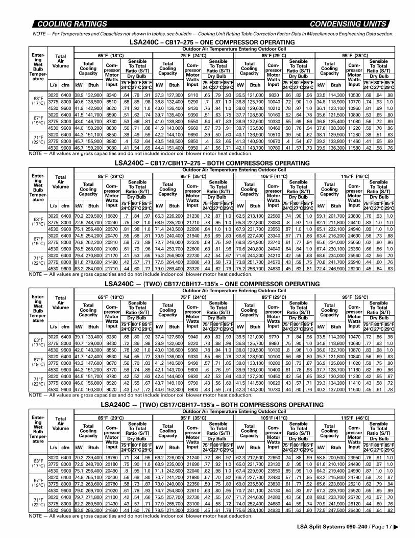
COOLING RATINGS CONDENSING UNITS
NOTE — For Temperatures and Capacities not shown in tables, see bulletin — Cooling Unit Rating Table Correction Factor Data in Miscellaneous Engineering Data section.
29°C27°C24°C
Enter-ingWetBulb
Temper-ature
TotalAir
Volume
L/s cfm
TotalCoolingCapacity
Btuh
Com-pressorMotorWattsInput
SensibleTo Total
Ratio (S/T)Dry Bulb Dry Bulb Dry Bulb Dry Bulb
SensibleTo Total
Ratio (S/T)
SensibleTo Total
Ratio (S/T)
SensibleTo Total
Ratio (S/T)Com-
pressorMotorWattsInput
Com-pressorMotorWattsInput
Com-pressorMotorWattsInput
TotalCoolingCapacity
TotalCoolingCapacity
TotalCoolingCapacity
Outdoor Air Temperature Entering Outdoor Coil
63°F(17°C)
67°F(19°C)
71°F(22°C)
BtuhkW kW kWBtuh BtuhkW
65°F (18°C) 75°F (24°C) 85°F (29°C) 95°F (35°C)
LSA240C – CB17–275 – ONE COMPRESSOR OPERATING
75°F 80°F 85°F
NOTE — All values are gross capacities and do not include indoor coil blower motor heat deduction.
3020 6400 38.9 132,900 8340 .64 .78 .91 37.3 127,300 9110 .65 .79 .93 35.5 121,000 9830 .66 .82 .96 33.5 114,300 10530 .68 .84 .983775 8000 40.6 138,500 8510 .68 .85 .98 38.8 132,400 9290 .7 .87 1.0 36.8 125,700 10040 .72 .90 1.0 34.8 118,900 10770 .74 .93 1.04530 9600 41.9 142,900 8620 .74 .92 1.0 40.0 136,400 9430 .76 .94 1.0 38.0 129,600 10210 .78 .97 1.0 36.1 123,100 10960 .81 .99 1.03020 6400 41.5 141,700 8590 .51 .62 .74 39.7 135,400 9390 .51 .63 .75 37.7 128,500 10160 .52 .64 .78 35.6 121,500 10890 .53 .65 .803775 8000 43.0 146,700 8730 .53 .66 .81 41.0 139,800 9550 .54 .67 .83 38.9 132,600 10330 .55 .69 .86 36.8 125,400 11080 .56 .72 .894530 9600 44.0 150,200 8830 .56 .71 .88 41.9 143,000 9660 .57 .73 .91 39.7 135,500 10460 .58 .76 .94 37.6 128,300 11220 .59 .78 .963020 6400 44.3 151,100 8850 .39 .49 .59 42.2 144,100 9690 .39 .50 .60 40.1 136,900 10510 .39 .50 .62 38.1 129,900 11280 .39 .51 .633775 8000 45.7 155,900 8980 .4 .52 .64 43.5 148,500 9850 .4 .53 .65 41.3 140,900 10670 .4 .54 .67 39.2 133,800 11460 .41 .55 .694530 9600 46.7 159,200 9080 .41 .54 .69 44.4 151,400 9950 .41 .56 .71 42.1 143,700 10780 .41 .57 .73 39.9 136,300 11580 .42 .58 .76
29°C27°C24°C75°F 80°F 85°F
29°C27°C24°C75°F 80°F 85°F
29°C27°C24°C75°F 80°F 85°F
29°C27°C24°C
Enter-ingWetBulb
Temper-ature
TotalAir
Volume
L/s cfm
TotalCoolingCapacity
Btuh
Com-pressorMotorWattsInput
SensibleTo Total
Ratio (S/T)Dry Bulb Dry Bulb Dry Bulb Dry Bulb
SensibleTo Total
Ratio (S/T)
SensibleTo Total
Ratio (S/T)
SensibleTo Total
Ratio (S/T)Com-
pressorMotorWattsInput
Com-pressorMotorWattsInput
Com-pressorMotorWattsInput
TotalCoolingCapacity
TotalCoolingCapacity
TotalCoolingCapacity
Outdoor Air Temperature Entering Outdoor Coil
63°F(17°C)
67°F(19°C)
71°F(22°C)
BtuhkW kW kWBtuh BtuhkW
85°F (29°C) 95°F (35°C) 105°F (41°C) 115°F (46°C)
LSA240C – CB17/CBH17–275 – BOTH COMPRESSORS OPERATING
75°F 80°F 85°F
NOTE — All values are gross capacities and do not include indoor coil blower motor heat deduction.
3020 6400 70.2 239,500 19820 .7 .84 .97 66.3 226,200 21230 .72 .87 1.0 62.5 213,100 22580 .74 .90 1.0 59.1 201,700 23830 .76 .93 1.03775 8000 72.9 248,700 20240 .75 .92 1.0 68.9 235,200 21710 .78 .95 1.0 65.3 222,800 23080 .8 .97 1.0 62.1 211,800 24410 .83 1.0 1.04530 9600 75.1 256,400 20570 .81 .98 1.0 71.4 243,500 22090 .84 1.0 1.0 67.9 231,700 23550 .87 1.0 1.0 65.1 222,100 24940 .89 1.0 1.03020 6400 74.5 254,200 20470 .55 .68 .81 70.5 240,400 21940 .56 .69 .83 66.6 227,400 23340 .57 .71 .86 63.4 216,200 24630 .58 .73 .883775 8000 76.8 262,200 20810 .58 .73 .89 72.7 248,000 22320 .59 .75 .92 68.8 234,900 23740 .61 .77 .94 65.6 224,000 25050 .62 .80 .964530 9600 78.5 268,000 21060 .61 .79 .96 74.4 253,700 22600 .63 .81 .98 70.6 240,800 24040 .64 .84 1.0 67.4 230,100 25360 .66 .86 1.03020 6400 79.4 270,800 21170 .41 .53 .65 75.3 256,900 22730 .42 .54 .67 71.6 244,300 24210 .42 .55 .68 68.6 234,000 25560 .42 .56 .703775 8000 81.6 278,600 21490 .42 .57 .71 77.5 264,400 23080 .43 .58 .73 73.8 251,700 24570 .43 .59 .75 70.8 241,700 25940 .44 .60 .764530 9600 83.2 284,000 21710 .44 .60 .77 79.0 269,400 23320 .44 .62 .79 75.2 256,700 24830 .45 .63 .81 72.4 246,900 26200 .45 .64 .83
29°C27°C24°C75°F 80°F 85°F
29°C27°C24°C75°F 80°F 85°F
29°C27°C24°C75°F 80°F 85°F
29°C27°C24°C
Enter-ingWetBulb
Temper-ature
TotalAir
Volume
L/s cfm
TotalCoolingCapacity
Btuh
Com-pressorMotorWattsInput
SensibleTo Total
Ratio (S/T)Dry Bulb Dry Bulb Dry Bulb Dry Bulb
SensibleTo Total
Ratio (S/T)
SensibleTo Total
Ratio (S/T)
SensibleTo Total
Ratio (S/T)Com-
pressorMotorWattsInput
Com-pressorMotorWattsInput
Com-pressorMotorWattsInput
TotalCoolingCapacity
TotalCoolingCapacity
TotalCoolingCapacity
Outdoor Air Temperature Entering Outdoor Coil
63°F(17°C)
67°F(19°C)
71°F(22°C)
BtuhkW kW kWBtuh BtuhkW
65°F (18°C) 75°F (24°C) 85°F (29°C) 95°F (35°C)
LSA240C — (TWO) CB17/CBH17–135’s – ONE COMPRESSOR OPERATING
75°F 80°F 85°F
NOTE — All values are gross capacities and do not include indoor coil blower motor heat deduction.
3020 6400 39.1 133,400 8280 .68 .80 .92 37.4 127,600 9040 .69 .82 .93 35.5 121,000 9770 .7 .84 .96 33.5 114,200 10470 .72 .86 .983775 8000 40.7 139,000 8430 .72 .86 .98 38.9 132,600 9220 .73 .88 .99 36.8 125,700 9980 .75 .90 1.0 34.8 118,800 10680 .77 .93 1.04530 9600 42.0 143,300 8550 .76 .92 1.0 40.0 136,600 9360 .78 .94 1.0 38.0 129,500 10130 .8 .96 1.0 36.0 122,700 10870 .83 .98 1.03020 6400 41.7 142,400 8530 .54 .65 .77 39.9 136,000 9330 .55 .66 .78 37.8 128,900 10100 .56 .68 .80 35.7 121,800 10840 .56 .69 .833775 8000 43.3 147,600 8670 .56 .70 .83 41.2 140,500 9490 .57 .71 .85 39.0 133,100 10280 .58 .73 .87 36.9 125,800 11020 .59 .75 .904530 9600 44.3 151,200 8770 .59 .74 .89 42.1 143,700 9600 .6 .76 .91 39.9 136,000 10400 .61 .78 .93 37.7 128,700 11160 .62 .80 .963020 6400 44.5 151,700 8780 .42 .52 .63 42.4 144,600 9630 .42 .53 .64 40.2 137,200 10450 .42 .54 .65 38.2 130,200 11230 .42 .55 .673775 8000 46.0 156,800 8920 .42 .55 .67 43.7 149,100 9790 .43 .56 .69 41.5 141,500 10620 .43 .57 .71 39.3 134,200 11410 .43 .58 .724530 9600 47.0 160,300 9020 .43 .57 .72 44.6 152,300 9900 .43 .59 .74 42.3 144,300 10730 .44 .60 .76 40.2 137,000 11540 .45 .61 .78
29°C27°C24°C75°F 80°F 85°F
29°C27°C24°C75°F 80°F 85°F
29°C27°C24°C75°F 80°F 85°F
29°C27°C24°C
Enter-ingWetBulb
Temper-ature
TotalAir
Volume
L/s cfm
TotalCoolingCapacity
Btuh
Com-pressorMotorWattsInput
SensibleTo Total
Ratio (S/T)Dry Bulb Dry Bulb Dry Bulb Dry Bulb
SensibleTo Total
Ratio (S/T)
SensibleTo Total
Ratio (S/T)
SensibleTo Total
Ratio (S/T)Com-
pressorMotorWattsInput
Com-pressorMotorWattsInput
Com-pressorMotorWattsInput
TotalCoolingCapacity
TotalCoolingCapacity
TotalCoolingCapacity
Outdoor Air Temperature Entering Outdoor Coil
63°F(17°C)
67°F(19°C)
71°F(22°C)
BtuhkW kW kWBtuh BtuhkW
85°F (29°C) 95°F (35°C) 105°F (41°C) 115°F (46°C)
LSA240C — (TWO) CB17/CBH17–135’s – BOTH COMPRESSORS OPERATING
75°F 80°F 85°F
NOTE — All values are gross capacities and do not include indoor coil blower motor heat deduction.
3020 6400 70.2 239,400 19780 .71 .84 .95 66.2 226,000 21240 .72 .86 .97 62.3 212,500 22650 .74 .88 .99 58.8 200,500 23950 .76 .91 1.03775 8000 72.9 248,700 20180 .75 .90 1.0 68.9 235,000 21690 .77 .92 1.0 65.0 221,700 23130 .8 .95 1.0 61.6 210,100 24490 .82 .97 1.04530 9600 75.1 256,400 20490 .8 .95 1.0 71.1 242,600 22040 .82 .98 1.0 67.4 229,900 23550 .85 .99 1.0 64.3 219,400 24990 .87 1.0 1.03020 6400 74.8 255,100 20430 .56 .68 .80 70.7 241,200 21980 .57 .70 .82 66.7 227,700 23430 .57 .71 .85 63.2 215,800 24790 .58 .73 .873775 8000 77.3 263,600 20780 .58 .73 .87 73.0 249,000 22350 .59 .75 .89 69.0 235,500 23830 .61 .77 .92 65.6 223,800 25210 .62 .79 .944530 9600 79.0 269,700 21020 .61 .78 .93 74.7 254,800 22610 .63 .80 .95 70.7 241,100 24130 .64 .83 .97 67.3 229,700 25520 .65 .85 .993020 6400 79.7 271,800 21100 .42 .54 .66 75.5 257,700 22730 .42 .55 .67 71.7 244,600 24280 .43 .56 .68 68.5 233,700 25720 .43 .57 .703775 8000 82.2 280,500 21430 .43 .57 .71 77.9 265,700 23100 .44 .58 .72 74.0 252,400 24680 .44 .59 .74 70.9 241,900 26120 .44 .60 .764530 9600 83.9 286,300 21660 .44 .60 .76 79.5 271,300 23340 .45 .61 .78 75.6 258,100 24930 .45 .63 .80 72.5 247,500 26400 .46 .64 .82
29°C27°C24°C75°F 80°F 85°F
29°C27°C24°C75°F 80°F 85°F
29°C27°C24°C75°F 80°F 85°F
LSA Split Systems 090–240 / Page 17 �
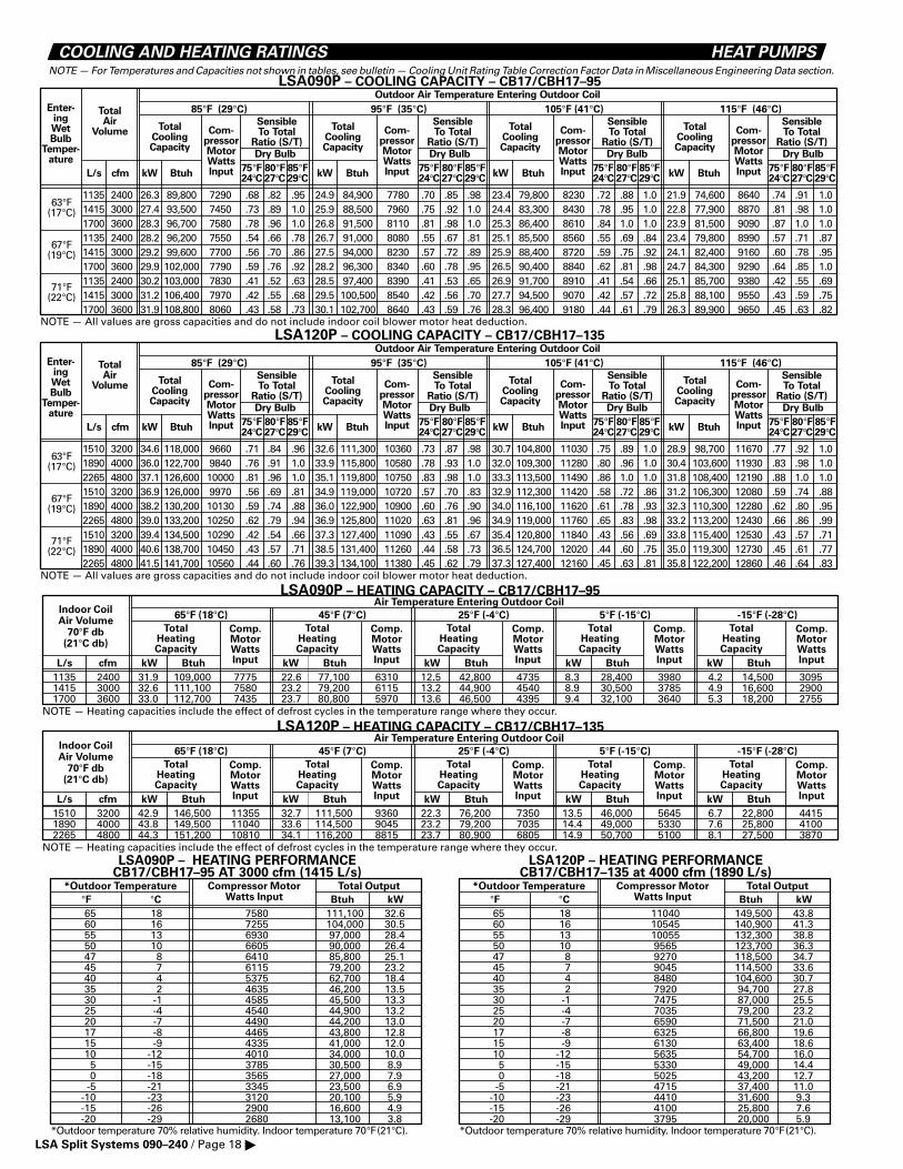
COOLING AND HEATING RATINGS HEAT PUMPSNOTE — For Temperatures and Capacities not shown in tables, see bulletin — Cooling Unit Rating Table Correction Factor Data in Miscellaneous Engineering Data section.
29°C27°C24°C
Enter-ingWetBulb
Temper-ature
TotalAir
Volume
L/s cfm
TotalCoolingCapacity
Btuh
Com-pressorMotorWattsInput
SensibleTo Total
Ratio (S/T)Dry Bulb Dry Bulb Dry Bulb Dry Bulb
SensibleTo Total
Ratio (S/T)
SensibleTo Total
Ratio (S/T)
SensibleTo Total
Ratio (S/T)Com-
pressorMotorWattsInput
Com-pressorMotorWattsInput
Com-pressorMotorWattsInput
TotalCoolingCapacity
TotalCoolingCapacity
TotalCoolingCapacity
Outdoor Air Temperature Entering Outdoor Coil
63°F(17°C)
67°F(19°C)
71°F(22°C)
BtuhkW kW kWBtuh BtuhkW
85°F (29°C) 95°F (35°C) 105°F (41°C) 115°F (46°C)
LSA090P – COOLING CAPACITY – CB17/CBH17–95
75°F 80°F 85°F
NOTE — All values are gross capacities and do not include indoor coil blower motor heat deduction.
1135 2400 26.3 89,800 7290 .68 .82 .95 24.9 84,900 7780 .70 .85 .98 23.4 79,800 8230 .72 .88 1.0 21.9 74,600 8640 .74 .91 1.01415 3000 27.4 93,500 7450 .73 .89 1.0 25.9 88,500 7960 .75 .92 1.0 24.4 83,300 8430 .78 .95 1.0 22.8 77,900 8870 .81 .98 1.01700 3600 28.3 96,700 7580 .78 .96 1.0 26.8 91,500 8110 .81 .98 1.0 25.3 86,400 8610 .84 1.0 1.0 23.9 81,500 9090 .87 1.0 1.01135 2400 28.2 96,200 7550 .54 .66 .78 26.7 91,000 8080 .55 .67 .81 25.1 85,500 8560 .55 .69 .84 23.4 79,800 8990 .57 .71 .871415 3000 29.2 99,600 7700 .56 .70 .86 27.5 94,000 8230 .57 .72 .89 25.9 88,400 8720 .59 .75 .92 24.1 82,400 9160 .60 .78 .951700 3600 29.9 102,000 7790 .59 .76 .92 28.2 96,300 8340 .60 .78 .95 26.5 90,400 8840 .62 .81 .98 24.7 84,300 9290 .64 .85 1.01135 2400 30.2 103,000 7830 .41 .52 .63 28.5 97,400 8390 .41 .53 .65 26.9 91,700 8910 .41 .54 .66 25.1 85,700 9380 .42 .55 .691415 3000 31.2 106,400 7970 .42 .55 .68 29.5 100,500 8540 .42 .56 .70 27.7 94,500 9070 .42 .57 .72 25.8 88,100 9550 .43 .59 .751700 3600 31.9 108,800 8060 .43 .58 .73 30.1 102,700 8640 .43 .59 .76 28.3 96,400 9180 .44 .61 .79 26.3 89,900 9650 .45 .63 .82
29°C27°C24°C75°F 80°F 85°F
29°C27°C24°C75°F 80°F 85°F
29°C27°C24°C75°F 80°F 85°F
29°C27°C24°C
Enter-ingWetBulb
Temper-ature
TotalAir
Volume
L/s cfm
TotalCoolingCapacity
Btuh
Com-pressorMotorWattsInput
SensibleTo Total
Ratio (S/T)Dry Bulb Dry Bulb Dry Bulb Dry Bulb
SensibleTo Total
Ratio (S/T)
SensibleTo Total
Ratio (S/T)
SensibleTo Total
Ratio (S/T)Com-
pressorMotorWattsInput
Com-pressorMotorWattsInput
Com-pressorMotorWattsInput
TotalCoolingCapacity
TotalCoolingCapacity
TotalCoolingCapacity
Outdoor Air Temperature Entering Outdoor Coil
63°F(17°C)
67°F(19°C)
71°F(22°C)
BtuhkW kW kWBtuh BtuhkW
85°F (29°C) 95°F (35°C) 105°F (41°C) 115°F (46°C)
LSA120P – COOLING CAPACITY – CB17/CBH17–135
75°F 80°F 85°F
NOTE — All values are gross capacities and do not include indoor coil blower motor heat deduction.
1510 3200 34.6 118,000 9660 .71 .84 .96 32.6 111,300 10360 .73 .87 .98 30.7 104,800 11030 .75 .89 1.0 28.9 98,700 11670 .77 .92 1.01890 4000 36.0 122,700 9840 .76 .91 1.0 33.9 115,800 10580 .78 .93 1.0 32.0 109,300 11280 .80 .96 1.0 30.4 103,600 11930 .83 .98 1.02265 4800 37.1 126,600 10000 .81 .96 1.0 35.1 119,800 10750 .83 .98 1.0 33.3 113,500 11490 .86 1.0 1.0 31.8 108,400 12190 .88 1.0 1.01510 3200 36.9 126,000 9970 .56 .69 .81 34.9 119,000 10720 .57 .70 .83 32.9 112,300 11420 .58 .72 .86 31.2 106,300 12080 .59 .74 .881890 4000 38.2 130,200 10130 .59 .74 .88 36.0 122,900 10900 .60 .76 .90 34.0 116,100 11620 .61 .78 .93 32.3 110,300 12280 .62 .80 .952265 4800 39.0 133,200 10250 .62 .79 .94 36.9 125,800 11020 .63 .81 .96 34.9 119,000 11760 .65 .83 .98 33.2 113,200 12430 .66 .86 .991510 3200 39.4 134,500 10290 .42 .54 .66 37.3 127,400 11090 .43 .55 .67 35.4 120,800 11840 .43 .56 .69 33.8 115,400 12530 .43 .57 .711890 4000 40.6 138,700 10450 .43 .57 .71 38.5 131,400 11260 .44 .58 .73 36.5 124,700 12020 .44 .60 .75 35.0 119,300 12730 .45 .61 .772265 4800 41.5 141,700 10560 .44 .60 .76 39.3 134,100 11380 .45 .62 .79 37.3 127,400 12160 .45 .63 .81 35.8 122,200 12860 .46 .64 .83
29°C27°C24°C75°F 80°F 85°F
29°C27°C24°C75°F 80°F 85°F
29°C27°C24°C75°F 80°F 85°F
1135 2400 31.9 109,000 7775 22.6 77,100 6310 12.5 42,800 4735 8.3 28,400 3980 4.2 14,500 30951415 3000 32.6 111,100 7580 23.2 79,200 6115 13.2 44,900 4540 8.9 30,500 3785 4.9 16,600 29001700 3600 33.0 112,700 7435 23.7 80,800 5970 13.6 46,500 4395 9.4 32,100 3640 5.3 18,200 2755
NOTE — Heating capacities include the effect of defrost cycles in the temperature range where they occur.
Indoor CoilAir Volume
70°F db(21°C db)
TotalHeatingCapacity
Comp.MotorWattsInputL/s cfm kW Btuh kW Btuh kW Btuh kW Btuh kW Btuh
TotalHeatingCapacity
Comp.MotorWattsInput
TotalHeatingCapacity
Comp.MotorWattsInput
TotalHeatingCapacity
Comp.MotorWattsInput
TotalHeatingCapacity
Comp.MotorWattsInput
Air Temperature Entering Outdoor Coil
65°F (18°C) 45°F (7°C) 25°F (-4°C) 5°F (-15°C) -15°F (-28°C)
LSA090P – HEATING CAPACITY – CB17/CBH17–95
1510 3200 42.9 146,500 11355 32.7 111,500 9360 22.3 76,200 7350 13.5 46,000 5645 6.7 22,800 44151890 4000 43.8 149,500 11040 33.6 114,500 9045 23.2 79,200 7035 14.4 49,000 5330 7.6 25,800 41002265 4800 44.3 151,200 10810 34.1 116,200 8815 23.7 80,900 6805 14.9 50,700 5100 8.1 27,500 3870
NOTE — Heating capacities include the effect of defrost cycles in the temperature range where they occur.
Indoor CoilAir Volume
70°F db(21°C db)
TotalHeatingCapacity
Comp.MotorWattsInputL/s cfm kW Btuh kW Btuh kW Btuh kW Btuh kW Btuh
TotalHeatingCapacity
Comp.MotorWattsInput
TotalHeatingCapacity
Comp.MotorWattsInput
TotalHeatingCapacity
Comp.MotorWattsInput
TotalHeatingCapacity
Comp.MotorWattsInput
Air Temperature Entering Outdoor Coil
65°F (18°C) 45°F (7°C) 25°F (-4°C) 5°F (-15°C) -15°F (-28°C)
LSA120P – HEATING CAPACITY – CB17/CBH17–135
7580 111,100 32.67255 104,000 30.56930 97,000 28.46605 90,000 26.46410 85,800 25.16115 79,200 23.25375 62,700 18.44635 46,200 13.54585 45,500 13.34540 44,900 13.24490 44,200 13.04465 43,800 12.84335 41,000 12.04010 34,000 10.03785 30,500 8.93565 27,000 7.93345 23,500 6.93120 20,100 5.92900 16,600 4.92680 13,100 3.8
*Outdoor temperature 70% relative humidity. Indoor temperature 70°F(21°C).
*Outdoor Temperature
°F °CCompressor Motor
Watts InputTotal Output
kWBtuh
65 1860 1655 1350 1047 845 740 435 230 -125 -420 -717 -815 -910 -125 -150 -18
-5 -21-10 -23-15 -26-20 -29
LSA090P – HEATING PERFORMANCECB17/CBH17–95 AT 3000 cfm (1415 L/s)
11040 149,500 43.810545 140,900 41.310055 132,300 38.89565 123,700 36.39270 118,500 34.79045 114,500 33.68480 104,600 30.77920 94,700 27.87475 87,000 25.57035 79,200 23.26590 71,500 21.06325 66,800 19.66130 63,400 18.65635 54,700 16.05330 49,000 14.45025 43,200 12.74715 37,400 11.04410 31,600 9.34100 25,800 7.63795 20,000 5.9
*Outdoor temperature 70% relative humidity. Indoor temperature 70°F(21°C).
*Outdoor Temperature
°F °CCompressor Motor
Watts InputTotal Output
kWBtuh
65 1860 1655 1350 1047 845 740 435 230 -125 -420 -717 -815 -910 -125 -150 -18
-5 -21-10 -23-15 -26-20 -29
LSA120P – HEATING PERFORMANCECB17/CBH17–135 at 4000 cfm (1890 L/s)
LSA Split Systems 090–240 / Page 18 �