spinchiller² duct...class of the building and therefore its value on the property market. it is...
TRANSCRIPT

SPINchiller² Duct
Nominal cooling capacity from 115 kW to 313 kW
The WSA-XSC2 liquid chillers are units for indoor installation with air ducted condensation.
A-CLASS OF ENERGY EFFICIENCY:modular Scroll technology, plate evaporators at heat exchange high efficiency, electronic expansion valves, ECOBREEZE plug fans with permanent magnet motors
ESEER SEASONAL EFFICENCY AT THE TOP OF ITS CLASS:significantly reduced operating costs over the entire annual cycle, that can be further improved with the DST control logic (Dynamic Supply Temperature) which maintains a constant system return temperature, activable by the user
GREAT COMPACTNESS AND ACCESSIBILITY:easy installation and maintenance even in shafts with restricted spaces
HIGH AVAILABLE STATIC PRESSURE:plug fans ECOBREEZE, high-performance and variable speeds that adapt to the system and ensure the proper expulsion of air through particularly complex channels
VERSATILITY OF USE:the different options available for the supply and return air flow allow you to easily connect the unit to the air channels
Technical Bulletin
HIGH EFFICIENCY AIR-COOLED LIQUID CHILLERFOR INDOOR INSTALLATION
WSA-XSC2 432-120D RANGE
BT13A003GB-03

2 SPINchiller² Duct BT13A003GB-03
Total comfort is required all year round, even in the most difficult application situations
Easy to position in the available shafts
The unit can be positioned easily in one of the following settings:
• in shafts;
• in service rooms, for instance, warehouses and store rooms;
• directly in the served area, in a visible position.
Versatility is ensured by the two solutions available for the air exhaust from the source side heat exchanger:
• the first solution is the installation in the shaft or in the service room, with rear intake and vertical ducted outlet.
• the second is the installation in a shaft or service room or in the environment, with intake and ducted outlet both from the rear.
REAR INTAKE AND DUCTED VERTICAL EXHAUST
REAR INTAKE AND DUCTED REAR EXHAUST
EXAMPLE OF EXTERNAL AIR EXHAUST GRILLE
This image represents only a few of positioning possibilities
Fans at variable speed for minimal noise emission
All units are supplied complete with electronic pressure control of the external exchanger. It automatically reduces the fan speed when the heat load is reduced.
Since the fans are the unit’s main noise source, the benefits are evident especially during the night hours, when the load is reduced but sensitivity to noise is enhanced.
All this translates into a reduction of sound pressure down to 8 dB(A) compared to full load operation in 90% of operating time of the unit.
Operating completely automatic
The microprocessor control automatically manages operation according to the maximum efficiency criterion and includes many safety and alarm management functions.
The interface terminal has a backlit graphic display and a multifunction access keypad. The multilevel menu is protected by different passwords according to the type of user. The daily / weekly timer comes as standard.

BT13A003GB-03 SPINchiller² Duct 3
Efficient precision
The sequential activation logics compressors allow:
• accurately following the load heating/cooling, supplying better comfort;
• reducing the number of compressor start-ups which is the main cause for wear and tear
• increasing the life cycle of the unit
• reducing time and costs for any repairs, thanks to the modularity of components, their reduced dimensions and the lower cost compared to semi-hermetic compressors.
Produces hot water freely
Condensation heat recovery:
• partial: it recovers about the 20% of the available heat (desuperheater)
• total: it recovers the 100% of the available heat
It allows the free DHW production for:
• hot water coil supply for reheat
• domestic hot water production (with intermediate exchanger)
• other processes or operations
Even for low water temperature
The unit is also perfectly adapted for use in process cooling where the low temperature version (Brine) together with the addition of glycol to the thermo-vector liquid produces chilled water down to –8 °C.
Load cover of the double-circuit units with 6 capacity steps

4 SPINchiller² Duct BT13A003GB-03
High energy efficiency within the annual cycle
Increases the building value
The unit is characterized by its high EER efficiency in cooling at full load, which exceeds the value of 2.7 and places it in the A-class of Eurovent energy efficiency.
The high efficiency reduces the complex primary energy requirements and the CO2 emissions compared to traditional solutions. It follows the improvement of the energy class of the building and therefore its value on the property market.
It is often possible to access the foreseen benefits to promote the use of the unit at low consumption.
Maximum efficiency is necessary with a part load
The system is required to generate maximum power only for a short amount of time. Therefore, it is essential to have the maximum efficiency under part load condition. This is the only way to actually reduce overall yearly consumptions.
Part load efficiency determines the seasonal efficiency
Seasonal efficiency is conventionally represented by ESEER parameters according to Eurovent and IPLV parameters according to ARI. Both give great importance to part load operation, since it is the predominant condition.
Modular Scroll technology boosts performance at part load
Since the maximum capacity is requested only for short periods of time, it is fundamental to place the maximum efficiency in the part load conditions. The unit uses high efficiency Scroll compressors. The advantages are:
• compressors manufactured in large ranges, with strict quality controls and maximum reliability thanks to the high production volumes
• each refrigerant circuit employs two Scroll compressors, almost always of different sizes in order to obtain more adjustment steps This way, only the necessary energy is supplied.
EUROVENT (ESEER) supply times reference and ARI (IPLV) reference for seasonal efficiency calculations.
THE SEQUENTIAL DEACTIVATION OF THE COMPRESSORS INCREASES EFFICIENCY

BT13A003GB-03 SPINchiller² Duct 5
Doubled efficiency
The heat exchange surface is sized for full capacity operation. Under part load condition, some compressors are automatically deactivated. Under this condition, in fact, the compressors in operation make use of a much larger surface.
This entails a reduced condensation temperature and an increased evaporation temperature. This way, the compressor capacity consumption is reduced with respect to the yield thereby increasing the overall efficiency of the unit.
It further increases the seasonal energy efficiency
The unit is standard equipped with DST (Dynamic Supply Temperature) logic control, activable by the user.
Unlike the traditional control logic that aims at maintaining the water supply temperature constant, the DST logic aims at keeping constant the water return temperature, modifying the supply temperature dynamically according to the load. In cooling at part load the evaporation temperature raises and therefore furtherly increases the seasonal energy efficiency.
The DST control allows a considerable consumption and operation costs reduction, especially in civil applications, upon verification of the air treatment system’s dehumidification capacity during cooling at part load.
The DST control is particularly interesting when combined with active thermodynamic fresh air systems which, thanks to their direct expansion circuit, allow them to operate the outdoor air treatment independently and autonomously. The water chiller can thus vary the system water supply temperature, thereby optimising energy efficiency in the yearly cycle.
Stable and reliable operating
The numerous technical solutions used in the refrigeration and hydraulic circuit as well as enabling very high levels of overall efficiency to be reached, also guarantee that the correct unit operating:
• the anti-freeze sensor on the outlet water in addition to the device which monitors the water flow work together to maintain unit safety and combat the risk of freezing.
• the electronic expansion valve (EEV) adapts quickly and precisely to the actual load required for use, thereby allowing for a more stable and accurate control compared to the mechanical thermostatic valves (TEV). All this results in further efficiency and greater compressor durability.
• furthermore, continuous adaptation to load conditions takes places without swings in the refrigeration circuit with the advantage of increasing the efficiency and the operating life of the compressor.
High efficient refrigerant
R410A is the mix of two refrigerants used in equal parts: R32 that supplies the heating capacity and R125 that controls the flammability. It is a chlorine free refrigerant (HFC) with numerous advantages:
• ODP (Ozone Depletion Potential) = 0
• high volumetric effect thanks to the high coefficient global thermal exchange and to the pressure variation (glide) which is almost nil during the evaporation phase
• elevated density and efficiency, with greater compactness of the refrigeration circuit and therefore the responsible use of materials and small refrigerant quantity, for a reduced environmental impact.
THE ELECTRONIC EXPANSION VALVE MAKES THE REFRIGERATION CIRCUIT HIGHLY STABLE AND EFFICIENT

6 SPINchiller² Duct BT13A003GB-03
Very high heat exchange efficiency
Thanks to the heat exchangers with large front surface and reduced depth, we obtain:
• improved operating temperature of the refrigeration circuit and hence improved efficiency, since this reduces the difference between the air temperature and the refrigerant fluid temperature inside the exchanger;
• fan consumption reduction, thanks to the lower depth of the exchanger which reduces pressure drop in the air flow. The automatic fan speed control, standard supplied, minimises moreover the air flow required for the correct operation and thus further reduces the consumptions;
• sound level reduction, since larger surface areas allow lower air speeds on the exchangers.
Versatility of reversed blades rotor
This particular type of rotor offers a wider field of operation compared with a traditional forward curved blade fan. When necessary, this can supply high static pressures simply by varying the number of revolutions. The accurate balancing and the self-lubricating bearings ensure its rotating stability over time.
The efficiency of the electronic controlled motor
The external rotor electric motor is driven by the continuous magnetic switching of the stator. The advantages are:
• the lack of brushes and the particular power supply increase efficiency by 70%;
• increase in the working life, thanks to the elimination of the brush wear;
• drastic reduction at the start-up of the starting current thanks to the electronic fan with the “soft start” function.
Advantages of direct coupling (plug fan)
The motor’s rotation is transmitted directly to the rotor, without the use of transmissions (belts and pulleys):
• the transmissions’ inefficiencies are eliminated;
• the transmissions’ wear and maintenance is eliminated.

BT13A003GB-03 SPINchiller² Duct 7
Efficiency of the ventilation system increases by 30%
The comprehensive ventilation system, made up of rotor and motor, is therefore very versatile and efficient.
Consumption is 30% lower than a ventilation system of the same capacity used by traditional units available on the market.
Higher levels of silence with composite
The fan impeller is made of a hybrid structure with aluminium alloy and plastic, with optimised aerodynamic blades. Thus electric absorption from the motor is reduced, obtaining a high level of silence whilst operating. This further technological progress increases the advantages in comparison with traditional centrifugal fans.
Electrical power absorption from the electric motor, manufacturer data - Example referred to the flow of 7,800 m3/h with static available pressure equal to 500 Pa
8 SPINchiller² Duct BT13A003GB-03
Reliability and saving throughout the entire life-cycle
System industrialisation
The unit may be supplied complete with the functions and components which are often supplied with the system. Thus reducing:
• design time: all the accessories are created to guarantee the best overall performance;
• installation costs: the accessories which are already mechanically connected, electrically wired and individually checked are ready to start operating immediately;
• dimensions: integration of system members into the unit reduces technical spaces and increases the space available for other uses. Its compact structure allows the unit to be carried through the shaft doors and to be positioned in service corridors.
The fan section is removable for an easier transport.
The whole upper part of the unit is easily removable. The reduction of the unit height and weight simplify its handling and transport.
The built-in pumps are versatile, ready-for-use and reliable
The optional hydronic assembly is complete with everything required for the system start-up and operating: antifreeze heaters, safety valve, charge/drain valves, pressure gauges. It also includes the pumping unit with the following solutions:
• Standard pump, with a wide range of available heads.
• HYDROPACK, the modular solution with two or three parallel pumps. Automatically reduces the water flow when in critical conditions, thereby preventing jams due to overloading, requiring the subsequent intervention of specialised technical personnel. It is very useful during start-ups, when restarting after operating breaks (e.g. at the weekend) or after a long period of inactivity.
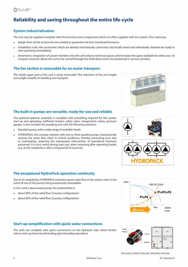
The exceptional HydroPack operation continuity
Due to its modularity, HYDROPACK maintains good water flow in the system even in the event of one of the pumps being temporarily unavailable.
In fact, with a deactivated pump, the residual flow is:
• about 80% of the rated flow (3 pump configuration)
• about 60% of the rated flow (2 pump configuration)
Start-up semplification with quick water connections
The units are complete with quick connections on the hydraulic side, which further reduce start-up times by eliminating pipe threading operations.
THE QUICK CONNECTIONS ARE STANDARD SUPPLIED

BT13A003GB-03 SPINchiller² Duct 9
The right air flow for every type of system
By setting the fan speed on the display, it is possible to modify the air flow, adapting the head yield to the pressure drop carried out by the system and thus, simplifying the start up of the unit. It is no longer necessary to calibrate or modify the transmissions in as much as it is the fan system which adapts to the system.
Controlled power supply
Proper power supply ensures optimal unit operation and protects its many electrical components.
The phase monitor, standard supplied:
• controls the presence and the exact sequence of the phases
• checks any voltage anomalies (-10%)
• automatically restarts the unit as soon as the proper power supply is restored.
A multifunction monitor is available as an extra, where limit values and the service schedule of Clivet’s Technical Support can be modified.
Demand limit
The partial or total activation of the compressors can be disabled to limit the overall electric capacity absorbed
The external signal is of analogical type 0-10 V / 4-20 mA. The greater the signal, the lower the capacity that the unit is enabled to deliver, activating the compressors and fans.
The Demand Limit function does not act on the control.
Modularity
In the event of particularly large buildings requiring high capacities, it is advisable to use several units.
The SPINchiller² units are designed to be connected in parallel in modular logic, thereby granting the following advantages:
• increased flexibility, enhanced by the control that can adapt to the load
• increased reliability, since the malfunction of one unit does not compromise the capacity supply of the other units.
• increased efficiency, since energy is produced where and when required, according to the served area.
The microprocessor control combined with ECOSHARE allows controlling up to 7 units in local network (1 Master unit and 6 Slave). MODULAR SYSTEM THAT ENHANCES SPINchiller² TECHNOLOGY ADVANTAGES

10 SPINchiller² Duct BT13A003GB-03
Remote system management
The unit can be remotely managed by:
• remote control with user interface
• Clivet P-Matic, supervision system able to be interfaced to other users
• clean contacts are supplied as standard for remote on/off control, compressor state display, enabling/disabling refrigerant circuit and any remote alarms
• different communication protocols to exchange information with the main supervision systems by serial line.
Energy measuring
Monitoring energy consumption and instant power employed is the starting point to improve the system’s energy management and efficiency. With the optional energy meter, the user displays all the information related to the unit’s electrical parameters on the interface built-in the unit or via the serial connection.

BT13A003GB-03 SPINchiller² Duct 11
Efficient use of energy with heat recoveryIn almost all systems fitted with a chiller used to produce chilled water there is also the need to have hot water. The recovery of condensation heat is an efficient way of producing hot water while the chiller is in operation. It has the double benefit of both reducing the heat load to the condenser, thereby eliminating dissipation costs and generating free hot water, thereby reducing the costs of the auxiliary heater.
Application versatility of recovery devicesThe hot water produced by heat recovery can be used in a number of ways: to reheat air in handling units, to preheat hot water for domestic use or industrial processes, to heat up water in swimming pools, showers and spas, to preheat hot water for laundries or industrial kitchens.
Post-heating in air handling units to control humidity levels in hospitals and labs
Preheating of hot water for domestic use or for industrial process
Heating of water in swimming pools, showers and SPAS
Preheating of hot water for laundries and industrial kitchens
Water heating upThe heat recovery device can be used to cover the entire heat load required. The hot water supply temperature is controlled via a modulating control valve that needs to be fitted on the system at the outlet of the recovery unit. The auxiliary heating device is recommended to cover the thermal energy demand when the chiller is not in operation or is operating at part load.
Example of how heat recovery is used to cover the entire heat demand and control the operating temperature
Water preheatingThe heat recovery device can be used to preheat water at the inlet of the main heating device (e.g. boiler). In this case, the demand for hot water is greater than the amount of heat recovered by condensation and the recovery device only covers part of the required heat load. By preheating the water, heating consumption levels are therefore reduced and the main heating device has a lower installed power requirement.
Example of how heat recovery is used to preheat hot water in the system
Domestic hot water productionThe heat recovery device can be used to produce water for domestic use. In order to prevent contamination of domestic water with the chiller’s process fluid, it is necessary to insert an intermediate heat exchanger. Using an inertial heat storage tank allows to have a reserve of preheated water and enables the intermediate exchanger to operate more efficiently.
Example of how heat recovery is used to preheat hot water for domestic use
A - Unit supply limit D - Partial energy recovery1 - Recovery exchanger 2 - Control modulating valve3 - Auxiliary heating device (ex.boiler) 4 - Electric pump with standby pump5 - Intermediate heat exchanger 6 - Inertial heat storageRW in - Recovery water input RW out - Recovery water outputT in - Drinkable water inlet T out - Drinkable water outlet to the auxiliary heater
The diagrams refer to partial energy recovery, though they also apply to total energy recovery (Clivet R). Please note that the diagrams are only meant as a guide.

12 SPINchiller² Duct BT13A003GB-03
Standard unit technical specifications
CompressorHermetic orbiting scroll compressor complete with motor over-temperature and over-current devices and protection against excessive gas discharge temperature. Fitted on rubber antivibration mounts and complete with oil charge.
An oil heater, which starts automatically, keeps the oil from being diluted by the refrigerant when the compressor stops.
The compressors are connected in TANDEM on a single refrigeration circuit and have a biphasic oil equalisation.
StructureSupporting structure realised in galvanised steel sheet able to supply excellent mechanical features and long-lasting resistance to corrosion.
The fan section is easily disassembled by removing the fixing screws and the electrical rapid connectors, thus reducing the height of the unit during transport operations.
PanellingExternal panelling with pre-painted panels covered with thermo-insulating and soundproofing material.
The housing panels can be removed by unbolting them and using the handles.
Internal ExchangerDirect expansion heat exchanger with braze welded stainless steel INOX AISI 316 plates and complete with external thermal/anti-condensation insulation.
the exchanger comes complete with:
• differential pressure switch, water side
• antifreeze heater to protect the water side exchanger, preventing the formation of frost if the water temperature falls below a set value.
External exchangerFinned coil exchanger made with copper pipes placed on staggered rows mechanically expanded to better adhere to the fin collar. The fins are made from aluminium with a corrugated surface and adequately distanced to ensure the maximum heat exchange efficiency.
Correct power supply to the expansion valve is ensured by the under-cooling circuit.
Protective coverings available on request.
FanECOBREEZE device (STD)
Plug fans without scroll with reverse blades driven by electronically-controlled “brushless” DC motors with direct coupling.
Refrigeration circuitRefrigeration circuit with:
• replaceable anti-acid solid cartridge dehydrator filter
• sight glass with moisture and liquid indicator
• electronic expansion valve
• high pressure safety pressure switch
• low pressure safety switch
• high pressure safety valve
• low pressure safety valve
• cutoff valve on liquid line
• cutoff valve on compressor supply

BT13A003GB-03 SPINchiller² Duct 13
Electrical panelThe capacity section includes:
• main door lock isolator switch
• isolating transformer for auxiliary circuit power supply
• compressor circuit breakers
• fan overload circuit breakers
• compressor control contactor
The control section includes:
• interface terminal with graphic display
• display of the set values, the error codes and the parameter index
• ON/OFF and alarm reset buttons
• derivative-integral-proportional control of the water temperature
• daily, weekly programmer of the temperature set-point and local-remote unit switch on management
• antifreeze protection water side
• compressor overload protection and timer
• prealarm function for water anti-ice and high refrigerant gas pressure
• self-diagnosis system with immediate display of the error code
• automatic compressor start rotation control
• compressor operating hour display
• remote ON/OFF control
• relay for remote cumulative fault signal
• inlet for demand limit (power input limitation according to a 0÷10V external signal)
• potential-free contacts for compressor status
• digital input for double set-point enabling
• phase monitor
Configurations• D - Partial energy recovery
• R - Total energy recovery
• B – Low water temperature
Accessories - hydronic assembly
• standard pump (n.b.: other types are available by head)
• HYDROPACK (n.b.: other types are available by head)
• couple of manual shut-off valves (accessory provided separately)
• steel mesh mechanical strainer (accessory separately supplied)
(note: to be located at the exchanger inlet. We disclaim any liability and make the guarantee void, if an appropriate mechanical filter is not provided inside the system)

14 SPINchiller² Duct BT13A003GB-03
Accessories• Finned coil protection grilles and shaft
• Copper / aluminium condensing coil with acrylic lining
• Copper / aluminium condensing coils with Aluminum Energy Guard DCC treatment
• High and low pressure gauges
• Cutoff valve on compressor supply and return
• Flush hydraulic connections
• Electrical panel ventilation
• Multifunction phase monitor
• Power factor correction capacitors (cosfi > 0.9)
• ECOSHARE function for the automatic management of a group of units
• Starting current reduction device (soft start)
• Serial communication module for BACnet supervisor
• Serial communication module for Modbus supervisor
• Serial communication module for LonWorks supervisor
• Microprocessor remote control unit (accessory separately supplied)
• Remote control via microprocessor remote control (accessory separately supplied)
• Mains power supply
• Energy meter
• Set-point compensation with 0–10 V signal
• Set-point compensation with outdoor air temperature probe
• Spring antivibration mounts (accessory separately supplied)
On request are available:
• copper /copper condensing coil
TestAll the units are factory-tested in specific steps, before shipping them. After the approval, the moisture contents present in all circuits are analyzed, in order to ensure the respect of the limits set by the manufacturers of the different components.
Unit for indoors installation only, away from atmospheric agents

BT13A003GB-03 SPINchiller² Duct 15
General technical data
Size 432 452 552 602 702 80D 90D 100D 110D 120D
Cooling
Cooling capacity 1 kW 116 123 148 165 185 206 240 269 296 315
Compressor power input 1 kW 37.4 40.6 49.4 55.2 62.0 69.4 80.3 90.8 100 115
Total power input 2 kW 41.5 44.7 53.4 59.2 67.3 74.7 86.8 97.3 107 124
Total recovery heating capacity 3 kW 144 154 185 207 232 259 301 338 372 404
Partial recovery heating capacity 3 kW 30.7 32.8 39.4 44.0 49.4 55.0 64.1 71.9 79.2 85.9
EER 1 2.79 2.76 2.76 2.78 2.75 2.75 2.77 2.76 2.76 2.54
Cooling capacity (EN14511:2013) 4 kW 115 123 147 164 184 205 239 268 295 313
Total power input (EN14511:2013) 4 kW 41.9 45.1 54.0 59.9 68.0 75.5 87.9 98.3 108 125
EER (EN 14511:2013) 4 2.76 2.73 2.72 2.74 2.71 2.71 2.72 2.73 2.73 2.51
ESEER 4 4.24 4.13 4.07 4.11 4.26 4.41 4.18 4.15 4.16 3.92
Compressor
Type of compressors SCROLL SCROLL SCROLL SCROLL SCROLL SCROLL SCROLL SCROLL SCROLL SCROLL
No. of compressors No 2 2 2 2 2 4 4 4 4 4
Rated power (C1) HP 43 45 55 60 70 40 45 50 55 60
Nominal capacity (C2) HP - - - - - 40 45 50 55 60
Std Capacity control steps No 3 3 3 2 3 6 6 6 6 4
Oil charge (C1) l 12.0 10.0 13.0 13.0 13.0 10.0 10.0 11.0 13.0 13.0
Oil charge (C2) l - - - - - 10.0 10.0 11.0 13.0 13.0
Refrigerant charge (C1) 5 kg 24 24 24 24 32 16 20 20 20 20
Refrigerant charge (C2) 5 kg - - - - - 16 20 20 20 20
Refrigeration circuits No 1 1 1 1 1 2 2 2 2 2
Internal exchanger
Type of internal exchanger 6 PHE PHE PHE PHE PHE PHE PHE PHE PHE PHE
Water flow rate (Utility Side) 4 l/s 5.50 5.90 7.00 7.80 8.80 9.80 11.4 12.8 14.1 15.0
Internal exchanger pressure drops 4 kPa 28 26 36 36 45 55 58 49 60 59
Water content l 8.90 10.1 10.1 11.9 11.9 10.5 12.9 17.6 20.1 20.1
External Section Fans
Type of fans 7 RAD RAD RAD RAD RAD RAD RAD RAD RAD RAD
Number of fans No 3 3 3 3 4 4 5 5 5 5
Standard airflow l/s 12333 12333 12333 12333 16444 16444 20556 20556 21389 22222
Connections
Water connections 2” 1/2 2” 1/2 2” 1/2 2” 1/2 2” 1/2 3” 3” 4” 4” 4”
Power supply
Standard power supply V 400/3/50 400/3/50 400/3/50 400/3/50 400/3/50 400/3/50 400/3/50 400/3/50 400/3/50 400/3/50
Noise Levels
Sound power in the duct 8 dB(A) 92 92 92 92 93 93 95 95 96 97
Dimensions
A - Length mm 3312 3312 3312 3312 4400 4400 5486 5486 5486 5486
B - Width mm 1151 1151 1151 1151 1151 1151 1151 1151 1151 1151
C - Height mm 2326 2326 2326 2326 2326 2326 2326 2326 2326 2326
Standard unit weights
Shipping weight kg 1408 1359 1482 1545 1831 1967 2331 2513 2642 2684
Operating weight kg 1430 1384 1507 1573 1861 1994 2369 2561 2695 2737
1. Data refer to the following conditions: - internal water exchanger = 12 / 7 °C - outdoor air temperature 35°C2. The Total Power Input value does not take into account the part related to the pumps and required to overcome
the pressure drops for the circulation of the solution inside the exchangers3. Option. Recovery exchanger water = 40/45°C4. Data calculated in compliance with Standard EN 14511:2013 referred to the following conditions: - Internal
exchanger water temperature = 12/7°C - external exchanger intake air temperature = 35°C
5. Indicative values for standard units with possible +/-10% variation. The actual data are indicated on the label of the unit.
6. PHE = plate exchanger7. RAD = radial fan8. Sound power measured in accordance with UNI EN ISO 9614 and Eurovent 8/1 standards for ducted unit with
available pressure equal to 120 Pa.

16 SPINchiller² Duct BT13A003GB-03
Electrical data
Size 432 452 552 602 702 80D 90D 100D 110D 120D
F.L.A. - Full load current at max admissible conditions
F.L.A. - Total A 104 112 126 141 163 181 217 228 245 274
F.L.I. Full load power input at max admissible conditions
F.L.I. - Total kW 64.1 67.5 77.7 86.5 102 108 130 141 150 168
M.I.C. Maximum inrush current
M.I.C. - Value A 331 363 377 392 483 408 468 479 496 525
M.I.C. with soft start accessory A 198 226 240 254 311 276 330 342 358 387
Power supply: 400/3/50 Hz. Voltage variation: max. +/-10%Voltage unbalance between phases: max 2 %
Electrical data refer to standard units; according to the installed accessories, the data can suffer light variations.
Operating range
Ta (°C)= external exchanger inlet air temperature (D.B.)
To (°C)= internal exchanger outlet water temperature
1 = Standard unit operating range
2 = Unit operating range in ‘B - Liquid low temperature’ configuration(40% ethylene glycol)
In the unit operating at part load the outdoor air minimum temperature limit is -7°C.
Water temperature to the internal exchanger
Max inlet water temperature 1 24 °C
Min. outlet water temperature 2 5 °C
Min. outlet water temperature 3 –7 °C
1. Standard unit. External exchanger intake air temperature 35°C2. Standard unit. External exchanger intake air temperature 35°C3. Unit in ‘Low water temperature (Brine)’ configuration and air (35 °C) entering the external heat exchanger. 40%
ethylene glycol based water.

BT13A003GB-03 SPINchiller² Duct 17
Performances in cooling
Size To (°)
Outdoor air temperature
25 30 35 40 45
kWf kWe kWf kWe kWf kWe kWf kWe kWf kWe
432
6 128 31.3 121 34.0 113 37.2 105 40.5 98.0 44.77 131 31.5 124 34.3 116 37.4 107 41.0 101 45.28 135 32.0 127 34.7 119 37.9 111 41.3 104 45.39 139 32.1 131 35.1 122 38.4 113 41.7 107 45.8
10 142 32.5 135 35.5 125 38.6 116 42.1 110 46.311 146 33.0 137 35.7 130 39.0 120 42.6 115 46.9
452
6 137 33.7 129 36.9 120 40.1 111 43.7 105 48.17 142 34.2 132 37.3 123 40.6 114 44.3 108 48.48 145 34.4 135 37.6 126 40.9 117 44.6 111 48.79 148 34.8 139 37.8 129 41.3 120 44.8 114 49.1
10 152 35.3 142 38.5 133 41.7 122 45.4 119 50.111 156 35.7 147 39.0 136 42.3 127 45.9 124 50.7
552
6 165 41.2 155 44.7 144 49.0 133 53.5 127 58.57 170 41.9 159 45.4 148 49.4 137 53.8 131 59.08 173 42.3 163 45.7 151 49.9 141 54.2 134 59.39 177 42.6 167 46.2 155 50.2 144 54.8 139 60.4
10 181 43.0 170 47.0 158 50.9 147 55.1 143 60.711 186 43.7 174 47.5 162 51.4 153 56.0 151 61.7
602
6 183 45.9 173 50.1 160 54.8 148 59.9 140 65.37 188 46.5 176 50.6 165 55.2 154 60.2 146 66.08 194 47.3 183 51.2 170 55.8 156 61.0 150 66.79 197 47.8 186 51.7 172 56.5 161 61.3 155 67.8
10 202 48.3 190 52.4 177 56.8 167 62.2 162 68.811 209 49.1 197 53.4 182 57.8 170 62.7 167 69.0
702
6 205 51.4 194 56.3 180 61.5 167 66.8 158 73.67 212 52.1 199 56.9 185 62.0 172 67.8 163 73.98 217 52.7 203 57.5 190 62.7 177 68.3 168 74.89 222 53.4 208 58.1 195 63.1 181 69.1 175 76.0
10 227 54.0 213 58.9 199 63.9 184 69.5 180 76.711 233 54.6 220 59.6 205 64.8 192 70.3 189 77.8
80D
6 228 58.1 215 63.3 200 69.0 185 75.1 177 82.47 234 58.8 221 63.9 206 69.4 191 76.0 182 82.68 242 59.5 227 64.6 210 70.1 196 76.4 188 83.49 246 60.1 231 65.1 214 70.5 200 76.9 193 84.7
10 249 60.7 236 65.8 219 71.6 205 77.8 199 85.111 257 61.4 241 66.6 225 72.1 211 78.3 210 86.5
90D
6 264 66.8 250 72.8 233 79.3 216 86.4 203 94.77 273 67.8 258 73.6 240 80.3 222 87.5 209 95.68 280 68.2 264 74.4 245 81.2 227 87.8 215 96.49 285 68.9 268 75.2 248 81.7 231 88.6 219 97.3
10 290 69.7 274 75.6 254 82.3 236 89.6 226 97.611 296 70.5 280 76.4 261 82.7 242 90.2 233 98.6
100D
6 301 75.6 282 82.1 263 89.8 244 98.2 233 1087 309 76.9 289 83.0 269 90.8 251 98.8 241 1098 315 77.7 296 84.0 274 91.4 255 99.7 247 1119 321 78.1 300 84.9 278 92.0 260 101 255 112
10 326 78.9 306 85.9 285 93.4 268 101 268 11411 336 80.3 317 86.9 293 94.1 277 102 275 114
110D
6 330 83.3 310 90.3 288 98.6 267 108 254 1187 338 84.2 317 91.4 296 99.7 276 109 266 1218 347 85.1 326 92.4 303 99.4 280 110 271 1219 352 85.5 329 93.3 306 101 284 110 279 122
10 357 86.4 335 94.4 315 103 294 111 292 12311 369 88.3 347 95.5 323 104 302 112 318 128

18 SPINchiller² Duct BT13A003GB-03
Size To (°)
Outdoor air temperature
25 30 35 40 45
kWf kWe kWf kWe kWf kWe kWf kWe kWf kWe
120D
6 354 95.8 332 104 308 114 288 124 282 1387 363 96.8 340 106 315 115 296 125 298 1418 370 98.4 350 107 323 116 303 126 300 1399 377 99.4 352 108 328 117 306 127 303 138
10 384 99.9 358 109 334 118 316 129 324 14311 392 101 370 110 346 120 328 130 330 143
kWf = Cooling capacity in kW-the data do not consider the pump share, required to overcome the pressure drop for the solution circulation inside the exchangers
kWe = Compressor power input in kW
To = Internal exchanger water outlet temperature (°C)
Inlet/outlet water temperature differential = 5°C
Electric fan performance
Size Static available pressure (Pa) 70 80 90 100 120 150 180 210 240 270 300 330
432
Standard airflow l/s 12333 12333 12333 12333 12333 12333 12333 12333 12333 12333 12333 12333
Fan RPM rpm 1599 1604 1609 1614 1624 1639 1655 1670 1686 1702 1718 1734
Total input kW 7,92 8,04 8,19 8,34 8,61 8,94 9,27 9,63 9,96 10,32 10,71 11,07
452
Standard airflow l/s 12333 12333 12333 12333 12333 12333 12333 12333 12333 12333 12333 12333
Fan RPM rpm 1599 1604 1609 1614 1624 1639 1655 1670 1686 1702 1718 1734
Total input kW 7,92 8,04 8,19 8,34 8,61 8,94 9,27 9,63 9,96 10,32 10,71 11,07
552
Standard airflow l/s 12333 12333 12333 12333 12333 12333 12333 12333 12333 12333 12333 12333
Fan RPM rpm 1615 1618 1627 1630 1637 1657 1672 1683 1699 1717 1735 1750
Total input kW 8,00 8,11 8,28 8,42 8,68 9,04 9,36 9,71 10,04 10,41 10,82 11,17
602
Standard airflow l/s 12333 12333 12333 12333 12333 12333 12333 12333 12333 12333 12333 12333
Fan RPM rpm 1647 1654 1654 1664 1671 1688 1703 1718 1738 1750 1770 1786
Total input kW 8,16 8,29 8,42 8,60 8,86 9,21 9,54 9,91 10,27 10,61 11,03 11,40
702
Standard airflow l/s 16444 16444 16444 16444 16444 16444 16444 16444 16444 16444 16444 16444
Fan RPM rpm 1631 1638 1638 1646 1658 1673 1686 1702 1716 1736 1754 1769
Total input kW 10,77 10,95 11,12 11,34 11,72 12,17 12,59 13,08 13,52 14,04 14,58 15,06
80D
Standard airflow l/s 16444 16444 16444 16444 16444 16444 16444 16444 16444 16444 16444 16444
Fan RPM rpm 1631 1638 1638 1646 1658 1673 1686 1702 1716 1736 1754 1769
Total input kW 10,77 10,95 11,12 11,34 11,72 12,17 12,59 13,08 13,52 14,04 14,58 15,06
90D
Standard airflow l/s 20555 20555 20555 20555 20555 20555 20555 20555 20555 20555 20555 20555
Fan RPM rpm 1629 1636 1643 1643 1656 1670 1688 1705 1721 1734 1752 1767
Total input kW 13,45 13,67 13,94 14,15 14,64 15,18 15,76 16,39 16,95 17,53 18,21 18,80
100D
Standard airflow l/s 20555 20555 20555 20555 20555 20555 20555 20555 20555 20555 20555 20555
Fan RPM rpm 1629 1636 1643 1643 1656 1670 1688 1705 1721 1734 1752 1767
Total input kW 13,45 13,67 13,94 14,15 14,64 15,18 15,76 16,39 16,95 17,53 18,21 18,80
110D
Standard airflow l/s 21388 21388 21388 21388 21388 21388 21388 21388 21388 21388 - -
Fan RPM rpm 1658 1663 1667 1672 1682 1696 1711 1726 1741 1756 - -
Total input kW 14,5 14,75 14,95 15,2 15,7 16,4 16,95 17,5 18,1 18,7 - -
120D
Standard airflow l/s 22222 22222 22222 22222 22222 22222 - - - - - -
Fan RPM rpm 1713 1719 1724 1728 1738 1751 - - - - - -
Total input kW 15,85 16,1 16,35 16,6 17,05 17,85 - - - - - -
The performance has been calculated in relation to the internal pressure drop of a standard unit.

BT13A003GB-03 SPINchiller² Duct 19
Correction factors for glycol use
% ethylene glycol by weight 5% 10% 15% 20% 25% 30% 35% 40%
Freezing temperature °C -2,0 -3,9 -6,5 -8,9 -11,8 -15,6 -19,0 -23,4
Safety temperature °C 3,0 1,0 -1,0 -4,0 -6,0 -10,0 -14,0 -19,0
Cooling Capacity Factor No 0,995 0,99 0,985 0,981 0,977 0,974 0,971 0,968
Compressor input Factor No 0,997 0,993 0,99 0,988 0,986 0,984 0,982 0,981
Internal exchanger Glycol solution flow Factor No 1,003 1,01 1,02 1,033 1,05 1,072 1,095 1,124
Pressure drop Factor No 1,029 1,06 1,09 1,118 1,149 1,182 1,211 1,243
The correction factors shown refer to water and glycol ethylene mixes used to prevent the formation of frost on the exchangers in the water circuit during inactivity in winter.
Fouling Correction Factors
Internal exchanger
m² °C / W F1 FK1
0.44 x 10 (-4) 1,0 1,0
0.88 x 10 (-4) 0,97 0,99
1.76 x 10 (-4) 0,94 0,98
The cooling performance values provided in the tables are based on the external exchanger having clean plates (fouling factor 1). For different fouling factor values, multiply the performance by the coefficients shown in the table.
F1 = Cooling capacity correction factorsFK1 = Compressor power input correction factor
Internal exchanger pressure drops
The pressure drops, water side, are calculated considering an average water temperature of 7°C.Q = water flow rate[l/s]DP = pressure drop [kPa]The water flow rate must be calculated with the following formulaQ [l/s] = kWf / (4,186 x DT)kWf = Cooling capacity in kWDT = Temperature difference between inlet / outlet water
To the internal exchanger pressure drops must be added the pressure drops of the mechanical steel mesh strainer that must be placed on the water input line. It is a device compulsory for the correct unit operation, and it is available as Clivet option. (See the HYDRONIC ASSEMBLY ACCESSORIES). If the mechanical strainer is selected and installed by the Customer, it is forbidden the use of filters with the mesh pitch higher than 1,6 mm, because they can cause a bad unit operation and also its serious damaging.

20 SPINchiller² Duct BT13A003GB-03
Admissible water flow ratesMinimum (Qmin) and maximum (Qmax) admissible water flow for the unit to operate correctly.
Size 432 452 552 602 702 80D 90D 100D 110D 120D
Qmin [l/s] 3,9 4,4 4,4 4,9 4,9 4,9 5,6 7,0 7,0 7,5
Qmax [l/s] 11,1 12,2 12,2 13,5 13,5 13,5 15,3 18,3 18,3 19,5
Exchanger operating range
Internal exchanger
PED (CE) kPaDPr DPw
4500 1000
DPr = Max. operating pressure referigerant gas sideDPw = Max. operating pressure water side (utility)
Attention! For different approvals contact our sales office
Overload and control device calibrations
open closed Value
High pressure switch [kPa] 4050 3300 –
Low pressure switch [kPa] 450 600 –
Low pressure switch (Brine and FCD) [kPa] 200 350 –
Antifreeze protection [°C] 3 5,5 –
High pressure safety valve [kPa] – – 4500
Low pressure safety valve [kPa] – – 2950
Max no. of compressor starts per hour [n°] – – 10
High discharge temperature safety thermostat [°C] – – 120
Sound levels
Size
Sound power level (dB) Sound power level
Sound pressure levelOctave band (Hz)
63 125 250 500 1000 2000 4000 8000 dB(A) dB(A)
432 69 76 92 87 85 86 79 76 95 76
452 69 76 91 87 85 86 79 76 95 76
552 69 76 92 87 85 86 79 76 95 76
602 69 76 92 87 85 86 79 76 95 76
702 70 78 93 89 87 88 81 78 96 77
80D 70 78 93 89 87 88 81 78 96 77
90D 72 80 95 90 89 89 83 80 98 78
100D 72 80 95 90 89 90 83 80 98 78
110D 73 80 96 91 90 90 84 81 99 79
120D 74 81 97 92 90 91 85 82 100 80
Sound levels refer to full load units, in test nominal conditions. The sound pressure level refers to 1 m. from the unit outer surface operating in open field.(standard UNI EN ISO 9614-2)Data referred to the following conditions:Internal exchanger water temperature = 12/7°COutdoor air temperature 35°CStatic available pressure 120 PaPlease note that when the unit is installed in conditions different from nominal test conditions (e.g. near walls or obstacles in general), the sound levels may undergo substantial variations.

BT13A003GB-03 SPINchiller² Duct 21
ConfigurationsConsult the special prospective reported in the final section to check for compatibility between different options.
EO - Horizontal air exhaustConfiguration which allows to reduce the height of the shaft where the unit is installed.
The air exhaust outlet, complete with coupling flange, is at the rear of the unit.
B - Water low temperature (Brine)Configuration also known as “Brine”. Enables an “unfreezable” solution to be cooled (for example, water and ethylene glycol in suitable quantities) up to a temperature of between +4°C and –8°C.
It includes:
• suitable exchangers with extra-thick closed-cell insulation
• electronic expansion valve, functional calibration and safety devices suitable for particular uses.
During the selection phase it is necessary to indicate the required operating type, the unit will be optimised on the basis of this: - Unit with single operating set-point (only at low temperature) - Unit with double operating set-point
The unit in this configuration has a different operation range, indicated in the operating range section.
In low temperature operation, some staging steps could not be available.
The glycol concentration must be chosen based on the minimum temperature the water can reach. The presence of glycol influences pressure drops on the water side and the unit’s output as indicated in the table reporting the ”correction factors for use with glycol”.
D - Partial energy recoveryA configuration which enables the production of hot water free-of-charge while operating in the cooling mode, thanks to the partial recovery of condensation heat that would otherwise be disposed of into the external heat source.
This option is also known as “desuperheater”. It is made up of a Inox 316 stainless steel brazed plate heat exchangers, suitable for recovering a part of the capacity dispersed by the unit (the dispersed heating capacity is equal to the sum of the cooling capacity and the electrical input capacity of the compressors).
The partial recovery device is considered to be operating when it is powered by the water flow which is to be heated. This condition improves the unit performance, since it reduces the condensation temperature: in nominal conditions the cooling capacity increases indicatively by 3.2% and the power input of the compressors is reduced by 3.6%.
When the temperature of the water to be heated is particularly low, it is wise to insert a flow control valve into the system hydraulic circuit, in order to maintain the temperature at the recovery output at above 35°C and thus avoid the condensation of the refrigerant into the partial energy recovery device.
The power delivered by the partial recovery is 20% of the thermal power dissipation (cooling + electrical power absorbed by the compressors)
D - Partial recovery device
1 - Internal exchanger2 - Compressors3 - Recovery exchanger4 - External exchanger5 - Expansion electronic valve
TW in chilled water inletTW out chilled water outlet
RW in - Recovery water inputRW out - Recovery water output
T - Temperature probePD - Differential pressure switchAE Outdoor air

22 SPINchiller² Duct BT13A003GB-03
Pressure drops of partial energy recovery exchanger
Q = water flow rate[l/s]DP = water side pressure drops (kPa)
R - Total energy recoveryA configuration which enables the production of hot water free-of-charge while operating in the cooling mode, thanks to the total recovery of condensation heat that would otherwise be disposed of into the external heat source. This solution increases the overall efficiency of the system in all cases where a high-level of hot water production is required. It is made up of a brazed plate heat exchanger made of 316 stainless steel, suitable for recovering all the unit heat capacity (equal to the sum of the cooling capacity and the electrical input capacity of the compressors), from the on-off type solenoid valve, from the supply and return temperature sensors in the hot water circuit and the related two-step integrated control logic.
Hot water availability is always subordinate to the production of chilled water.
See the following example:
1. cooling capacity request = 100% / Heating capacity request = 0% >Production only of cooling capacity;
2. cooling capacity request = 100% / Heating capacity request = 0% >Production of cooling and heating capacity by recovery;
3. cooling capacity request = 50% / Heating capacity request = 100% >Production of cooling and heating capacity by recovery, equal to the 50% of the requested heating capacity.
To prevent constant switching in the unit’s refrigeration circuit, it is necessary to install a storage tank with an adequate capacity in the system’s hot water circuit.
In the absence of hot water circulation in the recovery exchanger, the maximum inlet air temperature is reduced by approximately 2°C compared with the unit without “Total Energy Recovery” mode.
Check availability and compatibility of “R - Total energy recovery” with the other accessories in the “ Option compatibility” table.
Operating total energy recoveryWhen hot water is requested, the condensing coil is deactivated. Condensation takes place wholly within the recovery circuit.
R - Total recovery device1 - Internal exchanger2 - Compressors3 - Recovery exchanger4 - Total recovery enabling valve5 - External exchanger enabling valve6 - External exchanger7 - Expansion electronic valve
T - Temperature probeTW in chilled water inletTW out chilled water outlet
RW in - Recovery water inputRW out - Recovery water output
PD - Differential pressure switchAE = Outdoor air intake

BT13A003GB-03 SPINchiller² Duct 23
Not operating total energy recovery
When the recovery set-point has been satisfied, the condensing coil is reactivated. In this condition, the total recovery circuit operates as a Partial recovery circuit (Desuperheater).
Pressure drops of the total energy recovery exchanger
Q = water flow rate[l/s]DP = water side pressure drops (kPa)
R - Total recovery device1 - Internal exchanger2 - Compressors3 - Recovery exchanger4 - Total recovery enabling valve5 - External exchanger enabling valve6 - External exchanger7 - Expansion electronic valve
T - Temperature probeTW in chilled water inletTW out chilled water outlet
RW in - Recovery water inputRW out - Recovery water output
PD - Differential pressure switchAE = Outdoor air intake

24 SPINchiller² Duct BT13A003GB-03
Accessories - Hydronic assembly
ABU - Flush hydraulic connectionsAn option which simplifies the hydraulic connections which would otherwise be carried out within the unit (with the responsibility of the client).
Includes internal piping to the external unit panel, two quick connections flush to the unit, two outlet connections for the system connections which are to be soldered by the client.
The accessory is supplied installed built-in the unit.
A - Standard unitB - Unit with ABU option
The water connections flush with the unit are supplied as standard in units which are complete with at least one of the following options:
–Single pump
–HydroPack
It is also advisable to provide the system with the following components, which are excluded from the Clivet supplies:
- Cutoff valves, where not provided in the Clivet supply
- Piping support device and elastic vibration-proof joints
- Expansion tank (e.g. for closed circuit systems)
- Control thermometer on the supply
- Extra vent valves and discharge cocks where necessary
1PUS - Standard pumpOption supplied built-in the unit. Centrifugal electric pump with body and impeller made with AISI 304 or AISI 316 steel according to the models.
Three-phase electric motor with IP44-protection. Complete with thermoformed insulated casing, quick connections with insulated casing,non return valve, safety valve, pressure gauges, system load safety pressure switch, stainless steel antifreeze immersion heaters.
The various models which are available can be differentiated by the system available pressure.
STANDARD PUMP1 - Internal exchanger2 - Cutoff valve3 - Purge valve5 - Draw off cock6 - Cutoff valve with quick joints7 - Steel mesh strainer water side8 - Manometer9 - Safety valve (6 Bar)10 - Packaged electric pump with high efficiency impeller11 - Non return valve12 - System safety pressure switch (prevents the pumps from operating if no water is present)13 - Electric heater
T - Temperature probePD - Differential pressure switch
TW in chilled water inletTW out chilled water outlet
The grey area indicates further optional components.
IFWX - steel mesh strainer water sideCSVX - Couple of manual shut-off valves

BT13A003GB-03 SPINchiller² Duct 25
Performances of 1PUS options
Q = water flow rate[l/s]DP [kPa] = Available pressure
Attention: in order to obtain the available pressure values, the heads represented in these diagrams must be lowered of the internal exchanger
Attention: in order to obtain the available pressure values, the heads represented in these diagrams must be lowered of the “IFWX - steel mesh strainer water side” accessory (where present)
Single Pump Technical Specifications
Pump Rated power [kW] Nominal power [A]
PU2 1,4 2,6
PU3 1,8 3,2
PU20 1,8 3,4
PU22 3,3 5,6
PU23 2,2 5
PU24 3 6,2
PU25 4 7,7
PU26 5,5 10,4
CSVX - Couple of manual shut-off valvesIl kit allows to isolate the hydraulic circuit at the inlet and outlet.
It includes:
• no. 2 cast-iron shut-off butterfly valves with fast fittings and activation lever with a mechanical calibration lock
• no. 2 of quick connections
Installation is the responsibility of the Client, externally to the unit.
Accessory separately supplied

26 SPINchiller² Duct BT13A003GB-03
IFWX - Steel mesh strainer water sideThe device stops the exchanger from being clogged by any impurities which are in the hydraulic circuit. The mechanical steel mesh strainer must be placed on the water input line. It can be easily dismantled for periodical maintenance and cleaning. It also includes:
- cast-iron shut-off butterfly valve with quick connections and activation lever with a mechanical calibration lock;
- quick connections with insulated casing.
Steel mesh strainer pressure drops
EXCELLENCE 432-702 80D-90D 100D-120D
Diameter 2 1/2” 3” 4”
Degree of filtration 1,6 mm
The device compulsorily requires the installation of the “CSVX - A COUPLE OF SHUT-OFF VALVES TO MANUAL OPERATION” accessory
Installation is the responsibility of the Client, externally to the unit.
Check for the presence of the required hydraulic shut-off valves in the system, in order to undertake periodical maintenance.
We disclaim any liability and make the guarantee void, if an appropriate mechanical filter is not provided upstream of the system. Admitted filtration degree 1,6 mm
Accessory separately supplied
Q = water flow rate[l/s]DP = water side pressure drops (kPa)Note: the pressure drops are referred to the clean filter

BT13A003GB-03 SPINchiller² Duct 27
HydroPack
2 PM/3 PM - HydroPack with nr. 2/3 of pumpsOption supplied built-in the unit. Pumping unit made up of two or three electric pumps laid out in parallel, with auto-adaptive modular logic activation.
It enables the automatic reduction of the liquid flow rate in critical conditions, avoiding blocks due to overloading and consequential intervention work by specialised technical personnel.
Centrifugal electric pump with body and impeller made with AISI 304 or AISI 316 steel according to the models.
Three-phase electric motor with IP44-protection. Complete with thermoformed insulated casing, quick connections with insulated casing,non return valve, safety valve, pressure gauges, system load safety pressure switch, stainless steel antifreeze immersion heaters located at the return and supply point.
The various models which are available can be differentiated by the system available pressure.
The 2PM / 3PM option is supplied with a kit made up of 2 quick blind connections, for the removal of one pump in case of maintenance.
Provided with hydraulic interceptions to the outside of the unit (option ‘CSVX - A pair of manually operated shut-off valves’) to facilitate any major maintenance operations
HYDROPACK1 - Internal exchanger2 - Cutoff valve3 - Purge valve5 - Draw off cock6 - Cutoff valve with quick joints7 - Steel mesh strainer water side8 - Manometer9 - Safety valve (6 Bar)10 - Packaged electric pump with high efficiency impeller11 - Non return valve12 - System safety pressure switch (prevents the pumps from operating if no water is present)13 - Electric heater
T - Temperature probePD - Differential pressure switch
TW in chilled water inletTW out chilled water outlet
The grey area indicates further optional components.
IFWX - steel mesh strainer water sideCSVX - Couple of manual shut-off valves

28 SPINchiller² Duct BT13A003GB-03
Performances of the 2 PM/3 PM option (HydroPack)
Q = water flow rate[l/s]DP [kPa] = Available pressure
Attention: in order to obtain the available pressure values, the heads represented in these diagrams must be lowered of the internal exchanger
Attention: in order to obtain the available pressure values, the heads represented in these diagrams must be lowered of the “IFWX - steel mesh strainer water side” accessory (where present)
Hydropack technical specifications
PUMP RATED FLOW [kW] NOMINAL CURRENT [A]
2 x PU1 2 x 1,4 2 x 2,6
2 x PU2 2 x 1,4 2 x 2,6
2 x PU3 2 x 1,8 2 x 3,2
2 x PU20 2 x 1,8 2 x 3,4
2 x PU21 2 x 2,9 2 x 4,8
2 x PU22 2 x 3,3 2 x 5,6
3 x PU20 3 x 1,8 3 x 3,4
3 x PU22 3 x 3,3 3 x 5,6

BT13A003GB-03 SPINchiller² Duct 29
Accessories
PGCT- Finned coil protection grilles and shaftThis accessory is used to protect the external coil from the accidental contact with external things or people.
Ideal for installation in places where persons can pass from, such as car parks, terraces, etc.
The accessory is provided and installed built-in the unit.
This option is not suitable for application in sulphuric environments.
CCCA - Copper / aluminium condensing coil with acrylic liningCoils with copper pipes and aluminium fins with acrylic lacquering. Can be used in settings with moderately aggressive low saline concentrations and other chemical agents.
Attention!
- Cooling capacity variation -2.7%
- variation in compressor power input +4.2%
- operating range reduction -2.1°C
CCCA1 - Copper / aluminium condensing coils with Aluminium Energy Guard DCC treatmentA treatment which offers an optimal thermal exchange and guarantees and protects the finned coil exchangers from corrosion over time. Can be used in settings with very aggressive saline concentrations and other chemical agents in the air thus maintaining the performance of the coils over time.
CCCC - Copper / copper condensing coilCoils with copper pipes, copper fins and brass structure. Can be used in settings with moderately aggressive saline concentrations and other chemical agents.
This option is not suitable for application in sulphuric environments
Option available on request
MHP - High and low pressure gaugesAlthough the standard unit already displays digital parameters of pressures in the refrigeration circuit, this option allows analog display of refrigerant pressures on suction and discharge lines for ease of use by maintenance technicians.
The two liquid pressure gauges and corresponding pressure sockets are installed on the machine in an easily accessible location.
The device is installed built-in the unit.

30 SPINchiller² Duct BT13A003GB-03
SDV - Cutoff valve on compressor supply and returnAn option which integrates the supply cutoff valve, which is supplied as standard. The presence of the cock at the intake as well enables the compressors to be isolated and substituted without discharging the refrigerant from within the refrigeration circuit. This means that the extraordinary maintenance activities are facilitated.
The device is installed built-in the unit.
FANQE - Electrical panel ventilationThis option is necessary for very hot climates, where the outdoor temperature can be between +40°C and +50°C. It is made up of a system of forced ventilation, activated by a thermostat, which provides for the correct operating temperature to be maintained for the components inside the electrical panel. This option includes a thermostat which activates forced ventilation when necessary.
The device is installed and wired built-in the unit.
This accessory operates even when the unit is switched off provided that the power supply is maintained active and the unit continues to be connected.
The device operates only with powered units and not switched units. Be careful that you do not exceed a temperature of 50 ° C inside the electrical panel during storage or on the installed unpowered unit.
MF2 - Multifunction phase monitorThe phase monitor controls the electrical parameters of the power line to the unit. It works on the command circuit and orders the unit to be switched off when one of the following cases is present: when the phase connections do not respect the correct sequence, or when there is over voltage or under voltage for a certain amount of time (limit values of over and under voltage and the time interval can be manually and separately set). When the line conditions are re-established, the unit is re-armed automatically.
The device is installed and wired built-in the unit.
The device prevents sudden changes of voltage; however, the voltage must always be in a range between 380V and 480V.
PFCP - Power-factor capacitorsThe component is necessary to lower the phase difference between current and voltage in the electromagnetic components of the unit (e.g. asynchronous motors). The component allows to put the cosfi power factor to values on average higher than 0.9, reducing the network reactive power. This often leads to an economic benefit which the energy provider grants to the final user.
The device is installed and wired built-in the unit.
1. Compressors
2. Cutoff valve
3. Safety valve
4. SDV option

BT13A003GB-03 SPINchiller² Duct 31
ECS - ECOSHARE function for the automatic management of a group of unitsThe device allows automatic management of units that operate on the same hydraulic circuit, by creating a local communication network.
There are two control modes that can be set via a parameter during the activation stage. They both distribute the heat load on the available units by following the distribution logic to benefit from efficiency levels at part load.
Moreover:
Mode 1 - it keeps all the pumps active
Mode 2 - it activates only the pumps of the unit required to operate
The device allows for rotation based on the criterion of minimum wear and management of units in stand-by. There are various unit sizes. Every unit must be fitted with the ECOSHARE feature. The set of units is controlled by a Master unit.
The local network can be extended up to 7 units (1 Master and 6 Slave).
The unit supplied with this device can also be equipped at the same time with the RCMRX option and one of the CMSC8 / CMSC9 / CMSC10 options.
SFSTR – Starting current reduction deviceThis option is also known as “Soft starter”. An electronic device which automatically starts up the compressors gradually, reducing the starting current for the unit by around 40% in comparison with the nominal value.
This results in the electrical capacity system and the related protection devices being sized with lower parameters, thus having a lower initial investment cost.
The device is installed and wired built-in the unit.
CMSC8 - Serial communication module for BACnet supervisorThis enables the serial connection of the supervision system, using BACnet as the communication protocol. It enables access to the complete list of operational variables, commands and alarms. Using this accessory every unit can dialogue with the main supervision systems.
The device is installed and wired built-in the unit.
The configuration and management activities for the BACnet networks are the responsibility of the client.
The total length of each serial line do not exceed 1000 meters and the line must be connected in bus typology (in/out)
CMSC9 - Serial communication module for Modbus supervisorThis enables the serial connection of the supervision system, using Modbus as the communication protocol. It enables access to the complete list of operational variables, commands and alarms. Using this accessory every unit can dialogue with the main supervision systems.
The device is installed and wired built-in the unit.
The total length of each serial line do not exceed 1000 meters and the line must be connected in bus typology (in/out)
–– Absorbed current without SFSTR option− Absorbed current without SFSTR option

32 SPINchiller² Duct BT13A003GB-03
CMSC10 - Serial communication module for LonWorks supervisorThis enables the serial connection of the supervision system which uses the LonWorks communication protocol. It enables access to a list of operating variables, commands and alarms which comply with the Echelon® standard.
The device is installed and wired built-in the unit.
The configuration and management activities for the LonWorks networks are the responsibility of the client.
LonWorks technology uses the LonTalk® protocol for communicating between the network nodes. Contact the service supplier for further information.
The total length of each serial line do not exceed 1000 meters and the line must be connected in bus typology (in/out)
CONTA2 - Energy meterAllows to display and record the unit’s main electrical parameters. The data can be displayed with the user interface on the unit or via the supervisor through the specific protocol variables.
It is possible to control:
- voltage (V),
- absorbed current (A),
- frequency (Hz),
- cosfi,
- power input (KW),
- absorbed energy (KWh),
- harmonic components (%).
The device is installed and wired built-in the unit.
Only the following parameters are available on the LonWorks protocol: absorbed power (kW) and absorbed energy (kWh)
SPC4 - Set-point compensation with 0-10 V signalThis device enables the set-point to be varied which is pre-set using an external 0÷10 V signal.
The device is installed and wired built-in the unit.
SPC2 - Set-point compensation with outdoor air temperature probeThis device enables the set-point to be varied automatically which is pre-set depending on the outdoor air temperature. This device enables the liquid flow temperature to be obtained, which varies depending on external conditions, enabling energy savings throughout the entire system.
The device is installed and wired built-in the unit.

BT13A003GB-03 SPINchiller² Duct 33
Accessories separately supplied
RCMRX - Remote control via microprocessor remote controlThis option allows to have full control over all the unit functions from a remote position.
It can be easily installed on the wall and has the same aspect and functions of the user interface on the unit.
All device functions can be repeated with a normal portable PC connected to the unit with an Ethernet cable and equipped with an internet navigation browser.
The device must be installed on the wall with suitable plugs and connected to the unit (installation and wiring to be conducted by the Customer). Maximum remote control distance 350 m without auxiliary power supply. For distances greater than 350 m and in any case less than 700 m it is necessary to install the ‘PSX - Mains power unit’ accessory.
Data and power supply serial connection cable n.1 twisted and shielded pair. Diameter of the individual conductor 0.8 mm.
PSX - Mains power supply unitThe device allows the unit and the remote control to communicate with the user interface even when the serial line is longer than 350m.
It must be connected to the serial line at a distance of 350m from the unit and allows to extend the length to 700m maximum in total. The device requires an external power supply at 230V AC.
Power supply at 230V AC provided by Customer
AMMX - Spring antivibration mountsThe spring antivibration mounts are attached in special housing on the support frame and serve to smooth the vibrations produced by the unit thus reducing the noise transmitted to the support structure.

34 SPINchiller² Duct BT13A003GB-03
Option compatibility - WSA-XSC2 seriesREFERENCE DESCRIPTION 432 452 552 602 702 80D 90D 100D 110D 120D
CONFIGURATIONS AND MAIN ACCESSORIES
B Water low temperature o o o o o o o o o oD Partial energy recovery o o o o o o o o o oR Total energy recovery x x x x o o o o o o1PUS - STANDARD PUMP
PU2 Type 2 pump o o x x x x x x x xPU3 Type 3 pump o o x x x x x x x xPU20 Pump 20 x x o o o x x x x xPU22 Pump 22 o o o o o o o x x xPU23 Pump 23 x x x x x x o o o oPU24 Pump 24 x x x x x o o o o oPU25 Pump 25 x x x x x o o o o oPU26 Pump 26 x x x x x x x o o oPU2 + R Pump type 2 + Total energy recovery o o x x x x x x x xPU3 + R Pump type 3 + Total energy recovery o o x x x x x x x xPU20 + R Pump 20 + Total energy recovery x x o o x x x x x xPU22 + R Pump 22 + Total energy recovery o o o o x x o o o oPU23 + R Pump 23 + Total energy recovery x x x x x x o o o oPU24 + R Pump 24 + Total energy recovery x x x x x x o o o oPU25 + R Pump 25 + Total energy recovery x x x x x x o o o oPU26 + R Pump 26 + Total energy recovery x x x x x x x o o o2PM - HYDROPACK WITH NO.2 PUMPS
PU1 Type 1 pump o o o o x x x x x xPU2 Type 2 pump o o o o o o x x x xPU3 Type 3 pump o o o o o o o o x xPU20 Pump 20 x x x x x x o o o oPU21 Pump 21 x x o o o o o o o oPU22 Pump 22 x x o o o o o o o oPU1 + R Pump type 1 + Total energy recovery o o o o x x x x x xPU2 + R Pump type 2 + Total energy recovery o o o o x x x x x xPU3 + R Pump type 3 + Total energy recovery o o o o x x x x x xPU20 + R Pump 20 + Total energy recovery x x x x x x x x x xPU21 + R Pump 21 + Total energy recovery x x o o x x x x x xPU22 + R Pump 22 + Total energy recovery x x o o x x x x x x3PM - HYDROPACK WITH NO.3 PUMPS
PU20 Pump 20 x x x x x x o o o oPU22 Pump 22 x x x x x x o o o oPU20 + R Pump 20 + Total energy recovery x x x x x x x x x xPU22 + R Pump 22 + Total energy recovery x x x x x x x x x x
o Option
× Not available

BT13A003GB-03 SPINchiller² Duct 35
Dimensional drawingsWSA-XSC2 432-602
DAA1Z432_602_0
Date: 06/02/2013
1. Compressor compartmenti2. General electrical panel3. Exhaust radial electric fans4. External exchanger5. Power line input6. Internal exchanger water inlet(victaulic)
Standard unit or with pump option7. Internal exchanger water outlet(victaulic)
Standard unit or with pump option8. Recovery side exchanger water inlet (optional)
Position of the connections in relation with the recovery
9. Recovery side exchanger water outlet (optional) Position of the connections in relation with the recovery
10. Functional clearances11. Lifting brackets (removable)12. Fixing points13. Unit height without fan section
(R) Outdoor air return(EV) Vertical air exhaust(Standard)(EO) Horizontal air exhaust(OPTIONAL)
Size 432 452 552 602
A - Length mm 3312 3312 3312 3312
B - Width mm 1151 1151 1151 1151
C - Height mm 2326 2326 2326 2326
W1 Supporting Point kg 332 329 354 380
W2 Supporting Point kg 304 300 320 338
W3 Supporting Point kg 374 349 396 411
W4 Supporting Point kg 420 406 437 444
W5 Supporting Point kg 0.0 0.0 0.0 0.0
W6 Supporting Point kg 0.0 0.0 0.0 0.0
Shipping weight kg 1408 1359 1482 1545
Operating weight kg 1430 1384 1507 1573
Internal exchanger water connections Ø 2 ½” 2½” 2½” 2½”
Partial recovery water connections Ø 1¼” 1¼” 1¼” 1¼”
Total recovery water connections Ø 2” 2” 2” 2”
The presence of optional accessories may result in a substantial variation of the weights shown in the table.

36 SPINchiller² Duct BT13A003GB-03
WSA-XSC2 702-80D
DAA1Z702_80D_0
Date: 06/02/2013
1. Compressor compartmenti2. General electrical panel3. Exhaust radial electric fans4. External exchanger5. Power line input6. Internal exchanger water inlet(victaulic)
Standard unit or with pump option7. Internal exchanger water outlet(victaulic)
Standard unit or with pump option8. Recovery side exchanger water inlet (optional)
Position of the connections in relation with the recovery
9. Recovery side exchanger water outlet (optional) Position of the connections in relation with the recovery
10. Functional clearances11. Lifting brackets (removable)12. Fixing points13. Unit height without fan section
(R) Outdoor air return(EV) Vertical air exhaust(Standard)(EO) Horizontal air exhaust(OPTIONAL)
Size 702 80D
A - Length mm 4400 4400
B - Width mm 1151 1151
C - Height mm 2326 2326
W1 Supporting Point kg 425 449
W2 Supporting Point kg 434 443
W3 Supporting Point kg 403 484
W4 Supporting Point kg 599 618
W5 Supporting Point kg 0.0 0.0
W6 Supporting Point kg 0.0 0.0
Shipping weight kg 1831 1967
Operating weight kg 1861 1994
Internal exchanger water connections Ø 2½” 3”
Partial recovery water connections Ø 2” 2”
Total recovery water connections Ø 3” 3”
The presence of optional accessories may result in a substantial variation of the weights shown in the table.

BT13A003GB-03 SPINchiller² Duct 37
WSA-XSC2 90D-120D
DAA1Z90D_120D_0
Date: 06/02/2013
1. Compressor compartmenti2. General electrical panel3. Exhaust radial electric fans4. External exchanger5. Power line input6. Internal exchanger water inlet(victaulic)
Standard unit or with pump option7. Internal exchanger water outlet(victaulic)
Standard unit or with pump option8. Recovery side exchanger water inlet (optional)
Position of the connections in relation with the recovery
9. Recovery side exchanger water outlet (optional) Position of the connections in relation with the recovery
10. Functional clearances11. Lifting brackets (removable)12. Fixing points13. Unit height without fan section
(R) Outdoor air return(EV) Vertical air exhaust(Standard)(EO) Horizontal air exhaust(OPTIONAL)
Size 90D 100D 110D 120D
A - Length mm 5486 5486 5486 5486
B - Width mm 1151 1151 1151 1151
C - Height mm 2326 2326 2326 2326
W1 Supporting Point kg 267 270 290 290
W2 Supporting Point kg 522 574 621 630
W3 Supporting Point kg 298 302 321 322
W4 Supporting Point kg 187 185 186 185
W5 Supporting Point kg 714 830 872 900
W6 Supporting Point kg 381 400 405 410
Shipping weight kg 2331 2513 2642 2684
Operating weight kg 2369 2561 2695 2737
Internal exchanger water connections Ø 3” 4” 4” 4”
Partial recovery water connections Ø 2” 2” 2” 2”
Total recovery water connections Ø 3” 3” 3” 3”
The presence of optional accessories may result in a substantial variation of the weights shown in the table.

38 SPINchiller² Duct BT13A003GB-03
Page intentionally left blank

BT13A003GB-03 SPINchiller² Duct 39
Page intentionally left blank

CLIVET SPAVia Camp Lonc 25, Z.I. Villapaiera - 32032 Feltre (BL) - Italy Tel. + 39 0439 3131 - Fax + 39 0439 313300 - [email protected]
CLIVET UK LTD (Sales)4 Kingdom Close, Segensworth East - Fareham, Hampshire - PO15 5TJ - United KingdomTel. + 44 (0) 1489 572238 - Fax + 44 (0) 1489 573033 - [email protected]
CLIVET AIRCON LTD (Service and Maintenance Division)Units F5&F6 Railway Triangle Ind EST, Walton Road - Portsmouth, Hampshire - PO6 1 TG - United KingdomTel. + 44 (0) 2392 381235 - Fax + 44 (0) 2392 381243 - [email protected]
CLIVET ESPAÑA COMERCIAL S.L. (Sales)Calle Gurb, 17 1° 1a - 08500 Vic, Barcelona - EspañaTel. + 34 93 8606248 - Fax + 34 93 8855392 - [email protected]
CLIVET ESPAÑA S.A.U. (Service and Maintenance Division)Calle Real de Burgos n°12 - 28860, Paracuellos del Jarama, Madrid - EspañaTel. + 34 91 6658280 - Fax + 34 91 6657806 - [email protected]
CLIVET GmbHHummelsbütteler Steindamm 84, 22851 Norderstedt - GermanyTel. + 49 (0) 40 32 59 57-0 - Fax + 49 (0) 40 32 59 57-194 - [email protected]
CLIVET NEDERLAND B.V.Siliciumweg 20a, 3812 SX Amersfoort - NetherlandsTel. + 31 (0) 33 7503420 - Fax + 31 (0) 33 7503424 - [email protected]
CLIVET RUSSIAElektrozavodskaya st. 24, office 509 - 107023, Moscow, RussiaTel. + 74956462009 - Fax + 74956462009 - [email protected]
CLIVET MIDEAST FZCODubai Silicon Oasis (DSO), High Bay Complex, Ind Unit No. 3 - PO Box 28178 - DUBAI, UAETel. + 97 14 3208499 - Fax + 97 14 3208216 - [email protected]
CLIVET AIRCONDITIONING SYSTEMS PRIVATE LTD 3C3, Gundecha Onclave - Kherani Road, Saki Naka, Andheri (East), Mumbai 400 072 (INDIA)Tel. + 91 - 22 - 6193 7000 - Fax + 91 - 22 - 6193 7001 - [email protected]
w w w . c l i v e t . c o m