spiderfab: an architecture for self fabricating space · pdf filespiderfab: an architecture...
TRANSCRIPT

American Institute of Aeronautics and Astronautics
1
SpiderFab: An Architecture for Self-Fabricating Space Systems
Robert P. Hoyt,* Jesse I. Cushing,† Jeffrey T. Slostad,‡ Greg Jimmerson,† Todd Moser,† Greg Kirkos,† Mark L. Jaster,† Nestor R. Voronka§
Tethers Unlimited, Inc., Bothell WA, 98011, USA
On-orbit fabrication of spacecraft components can enable space programs to escape the volumetric limitations of launch shrouds and create systems with extremely large apertures and very long baselines in order to deliver higher resolution, higher bandwidth, and higher SNR data. This paper will present results of efforts to investigated the value proposition and technical feasibility of adapting several of the many rapidly-evolving additive manufacturing and robotics technologies to the purpose of enabling space systems to fabricate and integrate significant parts of themselves on-orbit. We will first discuss several case studies for the val-ue proposition for on-orbit fabrication of space structures, including one for a starshade de-signed to enhance the capabilities for optical imaging of exoplanets by the proposed New World Observer mission, and a second for a long-baseline phased array radar system. We will then summarize recent work adapting and evolving additive manufacturing techniques and robotic assembly technologies to enable automated on-orbit fabrication of large, com-plex, three-dimensional structures such as trusses, antenna reflectors, and shrouds.
Nomenclature ρ = material mass density D = beam diameter E = material modulus l = beam length m = the mass per unit length of a beam
I. Introduction HE SpiderFab effort, funded by NASA’s Innovative Advanced Concepts (NIAC) program, has investigated the value proposition and technical feasibility of radically changing the way we build and deploy spacecraft by ena-
bling space systems to fabricate and integrate key components on-orbit. Currently, satellites are built and tested on the ground, and then launched aboard rockets. As a result, a large fraction of the engineering cost and launch mass of space systems is required exclusively to ensure the system survives the launch environment. This is particularly true for systems with physically large components, such as antennas, booms, and panels, which must be designed to stow for launch and then deploy reliably on orbit. Furthermore, the performance of space systems are largely deter-mined by the sizes of their apertures, solar panels, and other key components, and the sizes of these structures are limited by the requirement to stow them within available launch fairings. Current State-Of-the-Art (SOA) deploya-ble technologies, such as unfurlable antennas, coilable booms, and deployable solar panels enable apertures, base-lines, and arrays of up to several dozen meters to be stowed within existing launch shrouds. However, the cost of these components increases quickly with increased size, driven by the complexity of the mechanisms required to enable them to fold up within the available volume as well as the testing necessary to ensure they deploy reliably on orbit. As a result, aperture sizes significantly beyond 100 meters are not feasible or affordable with current technol-ogies.
* CEO & Chief Scientist, 11711 N. Creek Pkwy S., D113, Bothell WA 98011, and AIAA Member. † Aerospace Engineer 11711 N. Creek Pkwy S., D113, Bothell WA 98011. ‡ V.P. & Chief Engineer, 11711 N. Creek Pkwy S., D113, Bothell WA 98011. § V.P. & Chief Technologist, 11711 N. Creek Pkwy S., D113, Bothell WA 98011.
T

American Institute of Aeronautics and Astronautics
2
On-orbit construction and 'erectables' technologies can enable deployment of space systems larger than can fit in a single launch shroud. The International Space Station is the primary example of a large space system constructed on-orbit by assembling multiple components launched separately. Unfortunately, the cost of multiple launches and the astronaut labor required for on-orbit construction drive the cost of systems built on the ground and assembled on-orbit to scale rapidly with size.
A. The SpiderFab™ Solution The SpiderFab architecture seeks to escape these size constraints and cost scaling by adapting additive manufac-
turing techniques and robotic assembly technologies to fabricate and integrate large space systems on-orbit. The vision that has motivated this effort is that of creating a satellite ‘chrysalis’, composed of raw material in a compact and durable form, ‘software DNA’ assembly instructions, and the capability to transform itself on-orbit to form a high-performance operational space system. Fabricating spacecraft components on-orbit provides order-of-magnitude improvements in packing efficiency and launch mass. These improvements will enable NASA, DoD, and commercial space missions to escape the vol-umetric limitations of launch shrouds to create systems with extremely large apertures and very long baselines. Figure 1 provides a notional illustration of the value proposition for SpiderFab relative to current state of the art deployable technologies. The larger antennas, booms, solar panels, concentrators, and optics created with SpiderFab will deliver higher resolution, higher bandwidth, higher power, and higher sensitivity for a wide range of missions. Moreover, on-orbit fabrication changes the cost equation for large space systems, ena-bling apertures to scale to hundreds or even thousands of meters in size with providing order-of-magnitude im-provements in system performance-per-cost. In this paper we will first describe a concept architecture for a system designed to fabricate and integrate large spacecraft components on-orbit. We call this architecture "SpiderFab" because it involves a robotic system that builds up large, sparse structures in a manner similar to that in which a spider spins its web: by extruding high-performance structural elements and assembling them into a larger structure. We will then evaluate the value propo-sition of this on-orbit fabrication architecture for several classes of spacecraft components, including antennas and starshades. Next, we will detail concept solutions for the technical capabilities required to realize the proposed ar-chitecture, and describe proof-of-concept testing performed to establish technical feasibility of these solutions. Fi-nally, we will describe an incremental development approach to enable maturation of these capabilities to mission readiness.
II. SpiderFab Architecture On-orbit construction has been investigated as a way to deploy large space systems for several decades, but aside
from the on-orbit assembly of the International Space Station (ISS), which required many launches and many hours of astronaut labor to complete, it has not been used in other operational missions because the potential benefits did not outweigh the attendant risks and costs. However, the recent rapid evolution of additive manufacturing processes such as 3D printing and automated composite layup, as well as the advancement of robotic manipulation and sensing technologies, are creating new opportunities to extend the on-orbit construction concept from simply assembly in space to a full in-space manufacturing process of fabrication, assembly, and integration. These additive manufactur-ing technologies can enable space programs to affordably launch material for spacecraft in a very compact and dura-ble form, such as spools of yarn, filament, or tape, tanks of liquid, bags of pellets, or even solid blocks of material, and then process the material on-orbit to form multifunctional 3D structures with complex, accurate geometries and excellent structural performance.
These capabilities can enable a radically different approach to developing and deploying spacecraft, one in which we verify, qualify, and launch the process, not the product.
Figure 1. SpiderFab Value Proposition. On-‐orbit fabrication of spacecraft components enables higher gain, sensitivity, power, and bandwidth at lower life-‐cycle cost.

American Institute of Aeronautics and Astronautics
3
A. The Self-Fabricating Satellite In developing a process for on-orbit fabrication of space systems, we have focused upon implementations that
will enable a space system to create and integrate its own components, so that it is self-fabricating. We call this the 'satellite chrysalis' approach, because each space system is launched with the material and tools needed to transform itself on-orbit into an operational system. An alternative approach is the 'orbital factory' approach, where a set of fabrication tools are launched to an orbital facility, such as the ISS, and this facility uses the same tools repeatedly to produce many space systems. We have chosen to focus upon the more challenging 'chrysalis' approach because although a factory can possibly achieve better economies of scale, launch mass, and reliability through repetition, the economics of the factory approach suffer from the transportation costs imposed by orbital dynamics. Specifical-ly, the ∆V required to transfer satellites produced at an orbital facility to operational orbits with different inclinations is extremely high, and the resulting launch mass penalty can easily exceed the satellite's mass. As a result, we be-lieve that in the near term, the factory approach will only be competitive in two applications: producing systems that will operate at or near the ISS, and in producing systems in geostationary orbit, where transfer ∆V's are relatively small. A self-fabricating capability that is economically competitive with conventional technologies will be competi-tive in any orbit. Moreover, the capabilities required for a factory are a subset of those required for a self-fabricating system, so if we can successfully implement a self-fabricating 'satellite chrysalis', then implementing an orbital sat-ellite factory will be straightforward.
B. Architecture Components On-orbit fabrication of spacecraft components will require (1) Techniques for Processing Suitable Materials to
create structures, (2) Mechanisms for Mobility and Manipulation of Tools and Materials, (3) Methods for Assembly and Joining of Structures, (4) Methods for Thermal Control of Materials and Structures, (5) Metrology to enable closed-loop control of the fabrication process, and (6) Methods for Integrating Functional Elements onto structures built on-orbit. 1. Material Processing and Suitable Materials
The self-fabricating satellite will require a capability to process raw material launched in a compact state into high-performance, multifunctional structures. Additive manufacturing processes such as Fused Filament Fabrication (FFF, also known under the trademark of Fused Deposition Modeling, or FDM®), Selective Laser Sintering (SLS), Electron Beam Melting, and Electron Beam Free-Form Fabrication (EBF3) are highly advantageous for this capabil-ity because they enable raw materials in the form of pellets, powders, or ribbons of filament to be melted and re-formed to build up complex 3D geometries layer by layer, with little or no wasted material. Figure 3 shows a photo of one of our developmental FFF machines printing a small sparse truss structure.
Working in the space environment presents both challenges and advantages for these additive manufacturing processes. The foremost is the microgravity environment in space. Most terrestrial additive manufacturing process-es rely upon gravity to facilitate positioning and bonding of each material layer to the previous layers, and in the microgravity environment we will not be able to rely upon this advantage. However, the lack of gravity also pre-sents a very interesting opportunity in that it enables structures to be built up in any direction without concern for distortions due to gravity. In 3D printers on the ground, gravity causes unsupported elements to slump, so structures with overhanging elements or large voids must be supported by additional materials that are removed after printing. In space, these support materials will not be required, and a 3D printer could 'print' long, slender elements, drawing a sparse structure in 3D like a spider spins its web, or build up a solid structure in concentric spherical layers, like an onion. Figure 2 shows several example sparse structures fabricated in the lab using ABS and PEEK thermoplastics.
Figure 2. Samples fabricated using FFM. On Earth, slumping due to gravity limits the element dimensions of sparse structures to centimeter scales, but this limit will not be present in microgravity.

American Institute of Aeronautics and Astronautics
4
Slumping due to gravity in the lab limited the free-standing lengths of the ele-ments to roughly a centimeter, but in zero-g the element lengths would be limited only by the reach of the fabrication tool.
A second technical challenge for on-orbit additive manufacturing is the vacu-um and thermal environment of space. Our preliminary testing of FFF processes in vacuum has indicated that the lack of an atmosphere is likely not an impedi-ment, but the absence of conductive and convective cooling will require careful design of any process that involves thermal processing of materials so that printed structures cool and solidify in the desired manner. Furthermore, temperatures and temperature gradients can vary greatly depending upon the solar angle and sun-lit/eclipse conditions, and methods for controlling these temperatures will be nec-essary to prevent undesired stresses from distorting structures under construction.
Although current 3D printing processes such as FFF can now handle a wide range of thermoplastics, and EBF3 can work with metals, the structural perfor-mance of these materials is still not optimal for large sparse space structures. If we are to pursue the construction of kilometer-scale systems, we must utilize ma-terials with the highest structural performance available. Additionally, the speed of current 3D printing processes are not suitable for creating large space systems. A typical FFF machine requires an entire afternoon to print an object the size of a coffee mug. For these reasons, we are pursuing an approach that fuses the flexibility of FFF with the performance and speed of another additive manu-facturing process: automated fiber layup. Essentially, we are working to develop a capability to rapidly '3D print' composite structures using high-performance fiber-reinforced polymers. This method will enable a robotic space system to build up very large, sparse structures in a manner similar to that in which a spider spins a web, extruding and pultruding structural elements and assembling them in 3-dimensional space to create large apertures and other spacecraft components. For this reason, we have termed this method the "SpiderFab™" process. The incorporation of pultrusion into the 3D printing process is particularly important, because it enables structural elements to be fab-ricated with high-modulus, high-tenacity fibers aligned in directions optimal for the service loads the structure must sustain.
The materials used in this process must be suitable for the space environment. In particular, they must be able to withstand the temperature extremes, UV light, radiation, and atomic oxygen that may be present in their operational orbit. Furthermore, low outgassing characteristics are necessary to prevent outgassed volatiles from contaminating optics, solar panels, and other components. In this work, we have focused on the use of Carbon Fiber reinforced Polyetheretherketone (PEEK) thermoplastics. These CF/PEEK composites have excellent structural performance, very high temperature tolerance, and very low outgassing characteristics. Although these materials are challenging to process due to the high melting temperature of PEEK, in this and other parallel efforts we have made excellent progress in developing techniques to perform thermoforming, pultrusion, and Fused Filament Fabrication with these materials. Although our work to date has focused on CF/PEEK composites, we should note that the SpiderFab pro-cess is readily adaptable to other composite choices, and we have also performed initial development with fiber-glass-PET composite materials. 2. Mobility & Manipulation
In order for a robotic system to fabricate a large structure, it will require means to move itself relative to the structure under construction, as well as to distribute the raw materials from the launch volume to the build area on the structure. Additionally, it will require the capability to manipulate structural elements to position and orient them properly and accurately on the structure. There are multiple potential solutions for both requirements. In de-veloping the SpiderFab architecture, we have focused on the use of highly dexterous robotic arms because, serendip-itously, under a separate contract effort we are currently developing a compact, dexterous robotic arm for nanosatel-lite applications. In our concept implementations, one or more such robotic arms will be used to position fabrication heads, translate the robot across the component under construction, and position structural elements for assembly. 3. Assembly & Joining
Once the robot has created a structural element and positioned it properly on the spacecraft structure, it will re-quire means to bond the element to the structure. This bonding could be accomplished using welding, mechanical fasteners, adhesives, and other methods. Because our SpiderFab efforts have focused upon the use of fiber-reinforced thermoplastics, we can take advantage of the characteristics of thermoplastics to accomplish fusion-bonding using a combination of heat and pressure.
Figure 3. TUI's FFF machine print-‐ing a sparse truss structure.

American Institute of Aeronautics and Astronautics
5
4. Thermal Control A significant challenge for fabricating precise structural elements, managing structural stresses in the elements,
and reliably forming fusion bonds between the elements will be managing the temperature of the materials in the space environment, where both mean temperatures and temperature gradient vectors can vary dramatically depend-ing upon the direction to the sun and the position in orbit. In the SpiderFab implementations we propose to use ad-ditives or coatings in the fiber-reinforced thermoplastics to cold-bias the materials and minimize their thermal fluc-tuations under different insolation conditions, and use contact, radiative, and/or microwave heating to form and bond these materials. 5. Metrology
Automated or tele-robotic systems for constructing large components will require capabilities for accurately measuring the component as it is built. This metrology will be needed at two scales: macro-scale metrology, to measure the overall shape of the component to ensure it meets system requirements, and micro-scale metrology, to enable accurate location of material feed heads with respect to the local features of the structure under construction. Technologies currently in use in terrestrial manufacturing processes, such as structured-light scanning and stereo-imaging, can be adapted to provide these functionalities. 6. Integration of Functional Elements
Once the SpiderFab system has created a base structure, it will also require methods and mechanisms to integrate functional elements such as reflective membranes, antenna panels, solar cells, sensors, wiring, and payload packages into or onto the support structure. Because most of these components can be packaged very compactly, and require high precision in manufacture and assembly, in the near term it is likely to be most effective to fabricate these com-ponents on the ground and integrate them on-orbit. In the long-term, it may be possible to implement additive man-ufacturing methods capable of processing many materials so that some of these components could be fabricated in-situ, but nonetheless it will only be advantageous to do so if on-orbit fabrication provides a significant improvement in launch mass or performance. The techniques for automated integration of functional elements onto a space struc-ture will depend upon the nature of the element. Reflective membranes and solar cells can be delivered to orbit in compact rolls or folded blankets and unrolled onto a structure using thermal bonding, adhesives, or mechanical fas-teners to affix them to the structure. Sensors, payloads, and avionics boxes can be integrated onto the structure us-ing mechanical fasteners. Wiring can be unspooled and clipped or bonded to the structure, and attached to payload elements using quick-connect plugs.
C. Concept Implementations 1. SpiderFab Truss-Fabricator for Large Solar Array Deployment
Figure 4 illustrates a concept for on-orbit fabrication of support structures for large solar arrays. In this concept, three SpiderFab "Trusselator" heads will extrude continuous 1st order trusses to serve as the longerons, and a fourth fabrication head on a 6DOF robotic arm will fabricate and attach cross-members and tension lines to create a truss support structure with 2nd-order hierarchy. As it extends, the support structure will tension and deploy a folda-ble/rollable solar array blanket prepared on the ground. To create the structural elements forming the truss-of-trusses, this system will process a “Continuous Fiber Reinforced Thermoplastic” (CFRTP) yarn consisting of high-modulus fibers co-mingled with thermoplastic filaments. This yarn can be wound in a highly compact spool for launch and then processed to create stiff composite structures. Figure 5 shows a proof-of-concept demonstration of a ‘Trusselator’ mechanism creating long truss structures. The spool shown on the left of Figure 5 holds enough yarn
Figure 4. Concept Method for Fabrication of Large, High-‐Performance Truss Structures to Support Solar Arrays.
Figure 5. First-‐Generation SpiderFab "Trusselator" Process.
Truss%Structure%for%Golay03%Sparse%Aperture%

American Institute of Aeronautics and Astronautics
6
to fabricate a 100m long, 2m diameter trussed beam.. 2. SpiderFab Bot for Assembly of Large Apertures
For other applications such as antenna reflectors, solar concentrators, solar sails, and structures for manned habi-tats, it will be desirable to implement a SpiderFab system able to create large two-dimensional or three-dimensional structures. A flexible fabrication capability could be enabled by a mobile "SpiderFab Bot" that uses several robotic arms for both mobility with respect to the structure under construction as well as for precise positioning of structural elements as it assembles the overall structure. To fabricate the structural elements, it uses two specialized 'spinneret' fabrication tools. One is an "Extruder Spinneret" used to convert spools of wound yarn or tape into high-performance composite tubes or trusses, as illustrated in Figure 6. It then uses a high-dexterity 'Joiner Spinneret' tool that adapts 3D printing techniques to create optimized, high-strength bonds between the structural elements, as illustrated in Figure 7, building up large, sparse support structures. Figure 8 illustrates the concept of the SpiderFab Bot building a support structure for an antenna or starshade onto a host satellite bus. Metrology systems for both micro-scale feature measurement and macro-scale product shaping enable the system to accurately place and bond new elements as well as ensure the overall structure achieves the desired geometry. Once the support structure is complete, the system uses its robotic manipulators and bonding 'spinneret' to traverse the structure and apply func-tional elements such as reflectors, membranes, meshes, or other functional components to the support structure, as illustrated notionally in Figure 9. These capabilities will enable a SpiderFab Bot to create large and precise aper-tures to support a wide variety of NASA, DoD, and commercial missions.
Figure 6. The SpiderFab Bot creates structural elements and adds them to the structure.
Figure 7. The SpiderFab Bot uses a 6DOF 3D printing tool to bond structural elements with joints optimized for the ser-‐vice loads.
Figure 8. Concept for a "SpiderFab Bot" constructing a sup-‐port structure onto a satellite.
Figure 9. The SpiderFab Bot then applies functional ele-‐ments, such as reflective membranes, to the support struc-‐ture.

American Institute of Aeronautics and Astronautics
7
III. Value Proposition for On-Orbit Fabrication The Phase I effort evaluated the value proposition for on-orbit fabrication of space systems using the SpiderFab
architecture, by first considering the trade-offs between building components on the ground versus building them on orbit, and identifying two key advantages that on-orbit fabrication can provide. We then reviewed NASA's Tech-nology Roadmaps to identify Technology Areas and future NASA missions where SpiderFab could provide signifi-cant advantages. Then we developed performance metrics to quantify the potential advantages that SpiderFab could provide for several space system components, including high-power solar arrays, phased array radars, optical oc-culters, and antenna reflectors. In each case, we found that SpiderFab can enable order-of-magnitude improvements in key performance metrics; in this proposal we will present the value proposition analyses for optical occulters and antenna reflectors, and refer the reviewer to our Phase I final report for details on the other case studies.
A. Build-on-Ground vs. Build-on-Orbit On-orbit fabrication of a space system can free the system design from the volumetric constraints of launch vehi-
cles and reduce the mass and engineering costs associated with designing the system to survive launch. Additional-ly, an on-orbit fabrication capability enables repair and reconfiguration after launch, reducing risks due to design errors and increasing mission flexibility. However, these advantages must be traded against the additional cost and complexity of enabling these components to be fabricated and integrated in an automated manner in the space envi-ronment. Furthermore, whereas in the conventional approach components are fabricated, integrated, and tested prior to launch, a program using on-orbit fabrication must commit and expend the costs associated with launch before these parts are created and integrated. Consequently, although our far-term goal is to enable fabrication and integra-tion of essentially all of a spacecraft on-orbit, we must approach this goal incrementally, focusing initial investment on classes of components where our current technology capabilities can provide a significant net benefit. Satellites and other spacecraft are typically composed of a number of subcomponents, ranging from bulk structures to actuated mechanisms to complex microelectronics. All of these components could, in theory, be fabricated on-orbit, but in-vesting in developing the capability to do so can only be justified if on-orbit fabrication can provide a dramatic net improvement in performance-per-cost. On-orbit fabrication can provide benefits primarily in two ways: launch mass reductions, and packing efficiency improvements.
B. Mass Optimization Fabricating a space structure on-orbit can reduce system mass because the design of structural components can
be optimized for the microgravity loads they must sustain in the space environment, not for the 100's of gravities shock and vibrations they would experience during launch. Additionally, large structures built on-orbit do not re-quire the hinges, latches, and other complex mechanisms needed by deployable structures, reducing the 'parasitic' mass of the structure and enabling it to be fully optimized for its design loads. Building a structure on-orbit, rather than designing it for deployment, also enables its geometry to be varied and/or tapered in an optimal manner throughout the structure, which for very large structures supporting well-defined loads can result in significant mass savings. Furthermore, it enables creation of structures with cross-sections that would be too large to fit in a launch shroud, taking advantage of geometric optimizations that can provide large improvements in structural performance. For example, the bending stiffness of a longeron truss increases as the square of its diameter D:
!"!= !
!!!!D! , (1)
where ρ is the material mass density, m is the mass per unit length of the beam, E is the material modulus, and Σ is a constant accounting for battens, cross members, and joints.1 Whereas a deployable truss designed to stow within a launch shroud will typically have a maximum diameter on the order of a meter, trusses fabricated on orbit can readi-ly be built with diameters of several meters or more, providing an order of magnitude improvement in stiffness per mass. Moreover, large structures can be built with 2nd or higher-order hierarchical geometry, enabling an additional 30-fold increases in structural performance.2
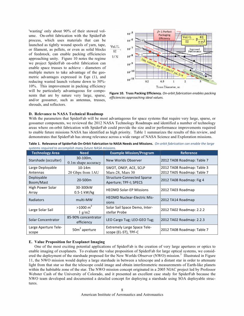
C. Packing Efficiency Improvements The second manner in which on-orbit fabrication can enable significant improvements is the packing efficiency
of large components. Figure 10, adapted from Reference [1], compares the packing efficiency of deployable trusses (flown) and erectable trusses (proposed). Existing deployable technologies fall one to two orders of magnitude short of ideal packing efficiency (ie - 95% to 99% of their stowed volume is "wasted"). Proposed erectable technologies, in which individual structural elements such as longerons and struts are launched in tightly packed bundles and then assembled on-orbit to fabricate large sparse structures, may be able to improve the packing efficiency somewhat,
American Institute of Aeronautics and Astronautics
8
'wasting' only about 90% of their stowed vol-ume. On-orbit fabrication with the SpiderFab process, which uses materials that can be launched as tightly wound spools of yarn, tape, or filament, as pellets, or even as solid blocks of feedstock, can enable packing efficiencies approaching unity. Figure 10 notes the regime we project SpiderFab on-orbit fabrication can enable space trusses to achieve - diameters of multiple meters to take advantage of the geo-metric advantages expressed in Eqn (1), and reducing wasted launch volume down to 50%-10%. This improvement in packing efficiency will be particularly advantageous for compo-nents that are by nature very large, sparse, and/or gossamer, such as antennas, trusses, shrouds, and reflectors.
D. Relevance to NASA Technical Roadmap With the parameters that SpiderFab will be most advantageous for space systems that require very large, sparse, or gossamer components, we reviewed the 2012 NASA Technology Roadmaps and identified a number of technology areas where on-orbit fabrication with SpiderFab could provide the size and/or performance improvements required to enable future missions NASA has identified as high priority. Table 1 summarizes the results of this review, and demonstrates that SpiderFab has strong relevance across a wide range of NASA Science and Exploration missions.
Table 1. Relevance of SpiderFab On-‐Orbit Fabrication to NASA Needs and Missions. On-‐orbit fabrication can enable the large systems required to accomplish many future NASA missions. Technology Area Need Example Mission/Program Reference
Starshade (occulter) 30-‐100m, 0.1m shape accuracy New Worlds Observer 2012 TA08 Roadmap: Table 7
Large Deployable Antennas
10-‐14m 20 Gbps from 1AU
SWOT, ONEP, ACE, SCLP Mars-28, Mars 30
2012 TA08 Roadmap: Table 3 2012 TA05 Roadmap: Table 7
Deployable Boom/Mast 20-‐500m
Structure-‐Connected Sparse Aperture; TPF-‐I; SPECS 2012 TA08 Roadmap: Fig 4
High Power Solar Array
30-‐300kW 0.5-‐1 kW/kg
HEOMD Solar-‐EP Missions 2012 TA03 Roadmap
Radiators multi-‐MW HEOMD Nuclear-‐Electric Mis-‐sions
2012 TA14 Roadmap
Large Solar Sail >1000 m2 1 g/m2
Solar Sail Space Demo, Inter-‐stellar Probe
2012 TA02 Roadmap: 2.2.2
Solar Concentrator 85-‐90% concentrator
efficiency LEO Cargo Tug; LEO-‐GEO Tug; 2012 TA02 Roadmap: 2.2.3
Large Aperture Tele-‐scope 50m2 aperture
Extremely Large Space Tele-‐scope (EL-‐ST), TPF-‐C 2012 TA08 Roadmap: Table 7
E. Value Proposition for Exoplanet Imaging One of the most exciting potential applications of SpiderFab is the creation of very large apertures or optics to
enable imaging of exoplanets. To evaluate the value proposition of SpiderFab for large optical systems, we consid-ered the deployment of the starshade proposed for the New Worlds Observer (NWO) mission.3 Illustrated in Figure 11, the NWO mission would deploy a large starshade in between a telescope and a distant star in order to attenuate light from that star so that the telescope could image and obtain interferometric measurements of Earth-like planets within the habitable zone of the star. The NWO mission concept originated in a 2005 NIAC project led by Professor Webster Cash of the University of Colorado, and it presented an excellent case study for SpiderFab because the NWO team developed and documented a detailed concept for deploying a starshade using SOA deployable struc-tures.
Figure 10. Truss Packing Efficiency. On-‐orbit fabrication enables packing efficiencies approaching ideal values.
In order to provide insight into the application of this performance metric, available data from existing beam hardware and proposed beams are shown plotted on the performance metric plot in figure 5. The curves of figure 5 are the same as those on figure 4. Most of the available beam data lies close to but slightly below the 6 = 4 line. This is an indication of the stiffness-to-mass state-of-the-art of space beams. The two square points above the 6 = 4 lines are data for graphite/epoxy coilable longeron beams developed for solar sails (Murphy, 2005, McEachen, 2005). The reason these beams are so efficient is that the longeron modulus was about 1.35 times the reference modulus of 137.8 GPa, and extreme measures were taken to minimize joint, batten, and diagonal mass. The SRTM boom was a 60 m beam that flew on the Space Shuttle (Umland, 2001). The data for figure 5 is presented in Table 1. The blank boxes in the table represent unavailable data. As can be seen in the figure, most available truss data is at or below the 6 = 4 reference curve. To increase the bending stiffness metric for a given diameter, it is necessary to either use a material with a higher E/U or reduce the mass in the battens, diagonals, and joints. It should be noted that the mass data in figure 5 does not include deployment canister mass or the mass for heating wires or insulation that may be required for the rigidizables. One measure of packaging efficiency, is the amount of volume the packaged beam requires to achieve a specific bending stiffness, EI. The volume of material in a beam can be determined from the equation shown on figure 4 by using the expression that M = U�V. The resulting equation is shown on figure 6 for the same composite reference values as used in figure 4. In this expression, a parameter E is introduced to account for the amount of packaged volume greater than the material volume. For example, E = 1 for perfect packaging and the packaged volume is equal to the material volume. To provide other references, lines for E = 10 and 100 are shown. In the lower right corner the two lower values are erectable structures. As would be expected, they have quite a good packaging factor. Also, the two squares at the left of the figure are the composite coilable beams (Murphy, 2005).
FIGURE 6. Packaging Volume Performance Metric. The other data points on the figure indicate that most deployable beams have a packing volume about 100 times the material volume. A potential use for the information of this chart is to understand the potential packaging volume advantage of in-space manufacturing. Presumably, in-space manufacturing of space structures using raw materials would result in packing volumes very close to the�E = 1 line on figure 6. Thus, it can be seen that erectable structures, the two lower right hand data points, would require about 5 times as much launch volume as the ideal case for in-space fabrication, after the facility is in place and in self sufficient operation. This information could assist in the decision process as to what future technologies to develop.
Graphite/Epoxy.Coilable.
=.1.Perfect.Packaging.Efficiency.
Erectables.On=orbit.Fabrica?on.
Fiberglass.Coilable.

American Institute of Aeronautics and Astronautics
9
The NWO starshade spacecraft designed by the NWO team, illustrated in Figure 12, uses several radially-deployed booms to unfurl an opaque metalized Kapton® blanket with folded rigid edge pieces. Using the largest available Delta-IVH launch shroud, this SOA deployable design could enable a starshade with a diameter of 62 m. The mass of the starshade component of the system (not including the spacecraft bus), was estimated by the NWO team to be 1495 kg.
Figure 12. SOA Deployable NWO Starshade Design. The NWO Starshade design folds to fit a 62m diameter structure within the largest available launch shroud. [Figures adapted from Ref 3]
Figure 13. Notional Comparison of Support Structures of the NWO Deployable Starshade and a SpiderFab Starshade. On-‐orbit fabrication enables creation of structures with variable dimensions and geometries optimized to the operational loads in the microgravity environment.
Figure 13 presents a notional comparison between the NWO deployable starshade's structural design and the structures enabled by SpiderFab on-orbit fabrication. The NWO starshade's opaque membrane is deployed and sup-ported by 16 radial spoke telescoping booms made of glass-reinforced polymer composite. The diameter of these booms is limited by packaging concerns to be less than a meter. Once deployed, these booms must support the opaque membrane against thrusts and torques applied by the central spacecraft. The lower half of Figure 13 illus-trates the kind of structure made possible by SpiderFab. We created this structure using ANSYS tools, using esti-
4.5$m$
7.7$m$
62$m$
Figure 11. New Worlds Observer starshade concept. A starshade positioned between a distant star and a telescope attenu-ates light from the star to allow the telescope to image planets orbiting that star. [Images from Ref 3]
NWO ASMCS Final Report
PI: W. Cash 1
New Worlds Observer: an Affordable and Efficient Way to Revolutionize Exoplanet Science
4m UV-Visible TELESCOPE Provides large collecting area and high resolution for both exoplanet science and general astrophysics. Carries 5 in-struments to enable a wide array of UV and Visible astrophysics
Deployable Apodized STARSHADE Provides 1010 starlight suppression to enable exoplanet imaging starting at IWA 50 mas, with 100% planet light throughput. Can be used with astrophysics objects like AGNs
H2OO2
Blue Sky
O3 edge
O (microns)
Counts/sec
0.3 0.4 0.5 0.6 0.7 0.8 0.9 1.0
H2OO2
Blue Sky
O3 edge
O (microns)
Counts/sec
0.3 0.4 0.5 0.6 0.7 0.8 0.9 1.0
~80,000 km
NASA Themes Addressed with Starshade: • Is there life elsewhere in the universe? • Are there other planetary systems like our own? • How do planetary systems form and evolve? • How are stars and stellar system formed? NASA Themes Addressed with Telescope: • What is the dark energy pulling the universe apart? • How did the first stars, galaxies and quasars form? • What are the ultimate fates of stars?
NWO’s primary science: discovery and characterization of terrestrial exoplanets
5390 26%4570591926%4688Total Launch Mass51 5%49515%49Separation System120 5%1141205%114Payload Adapter Fairing5219 16%4406574827%4525Spacecraft Wet Mass1220 0%1220n/an/an/aPropellant Mass (Xenon)476 0%4764480%448Propellant Mass (bi prop)3523 30%2710530030%4077Spacecraft dry massAlloc. Cont.CBE Alloc.Cont.CBE
Starshade Spacecraft Telescope SpacecraftAll mass in kg NWO Observatory Mass
0.12-0.5 mm < 1Ǝ GA UV Spectroscopy UVSpec 0.4-0.9 mm 10ƍ×20ƍ GA, Fine Guider WF Camera 1.7-3 mm N/A Fine alignment control Shadow Sensor 0.25-1.7 mm 10Ǝ x 3Ǝ Spectroscopy of Exoplanets ExoSpec 0.25-1.7 mm 26Ǝ x 26Ǝ Detecting/ Imaging Exoplanets ExoCam Bandpass FOV Primary Use Instrument
NWO uses a 3-step alignment process to center the starshade and telescope to within 1 m.
Background by Mary Pat Hybrk-Keith
L2 Orbit 6 months staggered launch ~800,000 km radius ~180 day period

American Institute of Aeronautics and Astronautics
10
mates of the torques and thrusts the structure must support and assuming the use of high-performance carbon fiber composites. Freed from the constraints of launch shroud dimensions and the requirement for a structure to be un-foldable or unfurlable, the support structure for the starshade could be made with a variable cross-section and varia-ble geometry. The structure could be several meters deep in the middle and taper out towards the periphery, and the concentration and geometry of the structural elements can be varied so as to optimize its strength to the operational loads. As illustrated in Figure 14, our analyses indicate that with the same amount of mass allocated for the SOA deployable starshade, a SpiderFab process could create a starshade structure of twice the diameter - four times the area. In this case the SpiderFab starshade mass estimate included an allocation of 250 kg + 150 kg margin for the robotic system required to fabricate the support structure (based upon the mass of our KRAKEN robotic arm and estimates derived from past experience on the Mars Polar Lander misson), and for the opaque membrane, we as-sumed the same total thickness of Kapton film (125 µm) used in the NWO design. In addition to increasing the size of the starshade that could be deployed with a given launch mass, SpiderFab also enables a 30-fold reduction in stowed volume, from 120 m3 for the SOA deployable approach down to 4 m3 for the on-orbit fabrication approach. This volume estimate assumed an 80% packing efficiency for the carbon fiber composite source material for the support structure (readily achievable with yarns or flat tapes) and included 2 m3 allocated for the SpiderFab robotic system) This reduction in stowed volume could enable the Starshade component of the NWO mission to launch on a Falcon-9 rather than a Delta-IVH, reducing its launch cost by a roughly a third.
Figure 14. Size increase achievable with SpiderFab. SpiderFab enables dramatic increases in aperture size with equal launch mass and significantly smaller stowed volume.
Doubling the size of the starshade would enable the NWO telescope to resolve planets 2 times closer to a star.4 This closer inspection would increase the number of potential Earth-like targets within the star's habitable zone by a factor of 8. Additionally, doubling the occulter size would double the maximum wavelength at which the starshade would provide sufficient attenuation, from 1µ to 2µ. This larger wavelength window would bring the system into the range where the James Webb Space Telescope (JWST) can operate, potentially enabling the JWST to be used as part of the NWO system, or at least as part of a pathfinder demonstration of the NWO architecture. By reducing the number of launches required to deploy a NWO system from two Delta-IV Heavies to one Falcon-9, and by increas-ing the number of planets the system could resolve, the SpiderFab approach could enable a net benefit of providing a 16-fold increase in the number of Earth-like planets the NWO mission could discover per life-cycle cost. More suc-cinctly, SpiderFab enables NASA to discover 16X more Earth-like planets per dollar.
F. Value Proposition for Large Antenna Reflectors Fundamentally the majority of NASA, DoD, and commercial space systems deliver one thing to their end-users:
data. The net quality of this data, whether it is the resolution of imagery, the bandwidth of communications chan-nels, or the signal-to-noise of detection systems, is largely driven by the characteristic size of the apertures used in the system. Deployable antennas reflectors therefore represent a very important potential market for application of on-orbit fabrication technologies.
We can compare the potential performance of SpiderFab for large antenna reflectors by comparing it with state-of-the-art deployable antennas such as the Astromesh reflectors produced by Northrop Grumman's Astro Aerospace

American Institute of Aeronautics and Astronautics
11
subsidiary, and the unfurlable antennas produced by Harris Corporation. The Astromesh reflectors use a tensegrity design in which a hoop-shaped truss deploys to spread open a conductive mesh, and a system of tension lines strung across the hoop serve to hold the mesh in the desired parabolic configuration. The Harris antennas typically use several radial spokes that unfold like an umbrella to spread apart and shape a conductive mesh. These tensegrity-based SOA deployables are exceptionally efficient in terms of mass, and we believe it is unlikely that an on-orbit fabrication approach can provide a significant improvement in launch mass. However, these deployables are not optimum from the perspective of stowed volume and cost, and therefore there is substantial opportunity for an on-orbit fabrication architecture such as SpiderFab to provide significant capability improvements by enabling much larger apertures to be deployed within the constraints of existing shrouds.
Figure 15. Mass and Cost Scaling of Deployable Antenna Reflectors. On-orbit fabrication of antenna apertures using Spi-derFab can change the cost equation for apertures, enabling deployment of very large apertures at lower cost than conventional deployable technologies.
Figure 15 plots the mass and estimated cost of current SOA deployable antennas.5 The size of the antenna imag-es used in the plot indicate the relative size and/or performance of the antenna. The plot demonstrates that the cost of these deployables increases rapidly with the size of the aperture reaching costs on the order of several hundred million dollars for apertures of a few dozen meters. The cost scaling is exponential with size due to the complexity of the additional folding mechanisms required as well as the facility costs needed to assemble and qualify very large components. Furthermore, because these deployable antennas are limited in terms of how compactly they can fold up, the largest aperture that can be deployed with these SOA technologies is on the order of several dozen meters. SpiderFab changes the cost equation for large antennas. For an antenna fabricated on-orbit, the cost will primarily be driven by the cost of building, launching, and operating the robotic system needed to construct it. In this analy-sis, we have estimated the recurring cost of such a robotic system at $25M-$75M, based upon use of an ESPA-class microsat bus such as the ~$20M Space Test Program Standard Interface Vehicle (STP-SIV) as well as estimates for the robotic systems based upon the Mars Polar Lander (MPL) robotic arm and the DARPA Phoenix mission. This 'base' cost may make SpiderFab non-competitive for small apertures. However, once that robotic system is paid for, the incremental cost for creating a larger antenna is primarily the cost for launching the required material and operat-ing the robotic system for a longer duration. In particular, we can eliminate the facility costs for assembling and testing very large antennas. As a result, the antenna life cycle cost will scale much more gently with aperture size, making antennas with diameters of hundreds of meters affordable.
IV. SpiderFab Technical Feasibility These SpiderFab concepts require capabilities for: (1) Processing Suitable Materials to Create Space Structures, (2) Mechanisms for Mobility and Manipulation of Tools and Materials, (3) Methods for Assembly and Joining of Struc-tures, (4) Methods for Thermal Control of Materials and Structures, (5) Metrology to enable closed-loop control of the fabrication process, and (6) Methods for Integrating Functional Elements onto structures built on-orbit.
0"
100"
200"
300"
400"
500"
600"
0" 100" 200" 300" 400" 500" 600"
Est.%Ap
erture%Cost%($M
)%
Aperture%Mass%(kg)%
Data$Source:$$Barnhart,$D.,$Phoenix$ID$Briefing$2/11/13$
Astromesh$
Harris$
Monocoque$
Image$Scale$Indicates$RelaDve$Size$or$Performance$
100m$SpiderFab$Dish$
SpiderFab$
Largest$Deployable$That$Fits$in$Current$Launch$Shrouds$

American Institute of Aeronautics and Astronautics
12
A. Processing Suitable Materials to Create Space Structures Creating satellite components with scales on the order of hundreds or thousands of meters will require the use of extremely high structural performance materials in order to achieve affordable launch masses. Additionally, creat-ing such large structures within an acceptable schedule will require techniques capable of processing these materials in a rapid fashion. To enable the maximal structural efficiency desired, we have focused upon materials and tech-niques for producing high-performance composite structures.
Materials: In space applications, structural elements will be fabricated using a material composed of a thermo-plastic and a high-performance fiber, such as polyetheretherketone (PEEK) and Carbon Fiber (PEEK/CF) compo-site. The carbon fiber will supply high tensile strength, stiffness, and compressive strength, and the PEEK will sup-ply shear coupling between the fibers. PEEK is a thermoplastic with high melting temperature, high service temper-ature, and low outgassing characteristics that has been used successfully on prior space flight missions. To mini-mize degradation of the PEEK polymer by UV radiation and to minimize thermal variations of the structure on-orbit, the PEEK thermoplastic can be doped with titanium dioxide.
In our initial efforts, we investigated two different material feedstock formats for use in the SpiderFab process. The first is a Continuous Fiber Reinforced Thermoplastic (CFRTP) yarn consisting of high-modulus fibers co-mingled with thermoplastic filaments. The second form of feedstock is tape of continuous fibers pre-impregnated with a polymer matrix, similar to that used in laminate style composite fabrication. In the SpiderFab architecture, these source materials will be launched in compact spools and then processed on-orbit to form structural elements such as trussed beams, tubes, lattices, and solid surfaces.
Processes: To validate the feasibility of creating large, sparse composite structures with these materials, we developed a hand-held 'SpiderFab' CFRTP pultrusion tool; this tool can be thought of as like a glue gun that extrudes thin, stiff composite elements. Figure 17 shows the tool, examples of structures we fabricated with the tool, and a demonstration of their strength.
Figure 17. Handheld ‘SpiderFab’ tool and samples of composite lattice structures fabricated with the tool. Pultrusion of CFRTP elements can enable free-‐form fabrication of large, sparse composite structures with excellent structural performance.
Additionally, we performed proof-of-concept demonstration of thermoforming a tape composed of unidirectional carbon fiber with a PEEK prepreg matrix into a composite tube using pultrusion/extrusion through a set of heated dies. This PEEK/CF tape is flexible and can readily be wound into compact spools, but after thermoforming into tubes can approach the performance of the best available struc-tural technologies.
B. Mobility and Manipulation: Both the Trusselator system illustrated in Figure 4 and the SpiderFab Bot illustrated in Figure 6 will require robotic manipulators and automated control software to provide mobility of the fabrication tool with respect to the structure as well as for positioning and joining structural elements together. A number of robotic arms designed for space operation exist that could serve this function, including the SU-MO robotic arm developed by NRL and MDA that is planned to be tested on the DARPA PHOENIX mission and the robotic arms used in the Robonaut system. In our concept designs, we have baselined the use of the compact, high-dexterity "KRAKEN™" robotic arm that we have developed for nanosatellite servicing and
Figure 16. KRAKEN Robotic Arm Prototype. The KRAKEN is a 7DOF robotic arm with 1m reach. Two KRAKEN arms will stow within a 3U volume.

American Institute of Aeronautics and Astronautics
13
assembly applications. A developmental model of the 7DOF KRAKEN arm is shown in with a notional SpiderFab feed head mounted on a 3DOF 'carpal-wrist' gimbal.
C. Assembly & Joining To enable a robotic system to construct complex sparse lattice structures, we developed a concept design for a spe-cialized “Joiner Spinneret” end effector that uses Fused Filament Fabrication (FFF) techniques to join tubular truss elements. This tool, illustrated in Figure 18, is designed to approach the new tubes to be joined from the side (radi-ally), clamp onto the tube, and then use a rotary stage to reach 360 degrees around the end of the tube, while allow-ing the end effector to approach and retract radially from the side of the tube. As illustrated in Figure 18, a ‘finger’ with 3 independently cable-driven joints allows the spinneret print head to reach every spot and every angle needed to print a uniformly filleted joint, even when it requires reaching between tubes at tightly angled orientations to each other. The smaller scale motion stages built into the finger allow the new tube to be fixtured by the same robotic arm that is performing the joining, which simplifies the accuracy and obstacle avoidance schemes required in gener-ating the tool paths. Figure 19 shows a multi-element joint fabricated with optimized geometry using 3D printing, assembled with carbon composite tubes. The joiner spinneret can also be used to add brackets, bolt-holes, and other features to enable mounting of payloads and functional elements, as illustrated notionally in Figure 20.
Figure 18. Conceptual Tube-‐Joining Process Using Fused Filament Fabrication. The Spinneret uses a FFF head on the joining tool to fashion a joint between the element and the existing structure.
Figure 19. Prototype 3D-‐Printed Optimized Joint. Use of 3D-‐printing techniques with a highly dexterous print head can enable fabrication of joints optimized for the service loads, maximizing structural efficiency.
Figure 20. SpiderFab Bot Printing Mounting Feature onto Truss Node. Mounting interface features can be printed onto the joints after completion of the truss structure, enabling fine-‐tuning of placement of mirrors or other functional ele-‐ments.

American Institute of Aeronautics and Astronautics
14
D. Thermal Control Thermoforming and bonding of fiber-reinforced thermoplastics requires control of the temperature of both the mate-rial being processed and the structure it is being applied to in order to ensure reliable bonding and minimize stresses and distortions in the structure. This will be a significant challenge in the space environment, as temperatures and thermal gradients can vary dramatically depending upon solar angle and eclipse/sunlit conditions. Terrestrial high-precision FDM 3D printing machines typically house the entire workspace and material processing tools within a thermally-controlled enclosure to minimize warping of parts due to coefficient of thermal expansion (CTE) behav-ior. This solution will not be practical for building very large space structures. To address this challenge, we pro-pose to pursue a method combining low-CTE material combinations, surface coatings to minimize temperature vari-ations, and local spot-heating to ensure the temperatures necessary for reliable bonding. To ensure a joint is at the proper temperature to enable reliable fusing of new material to it, we can use spot-heating with IR radiators, lasers, RF heaters, or conductive-contact heaters. Figure 21 illustrates a concept approach to using an IR laser pre-heating areas onto which the tool will 3D print material, and Figure 22 shows a photo of an initial test of using a high-power IR laser to spot-heat a section of a 3D-printed joint. The initial testing indicated that this approach is feasible, but further work will be required to develop a reliable and controllable process. An additional method that may be fea-sible would be for the SpiderFab Bot to use positionable shades (such as the gimbaled solar panel shown in Figure 9) and/or reflectors to control insolation conditions within the work volume
Figure 21. Concept for laser pre-‐heating of joint material. Low equilibrium temperatures may necessitate pre-heating of the joint surfaces prior to fusing additional material onto previously printed parts.
Figure 22. Testing of Plastic Joint Surface Pre-‐Heating with 700mw IR Laser. We have experimented with non-contact methods of heating the joint material to bring cold parts into the processable range.
E. Metrology On-orbit construction of large space system components in an automated or telerobotic manner will require capabili-ties for measuring the component as it is built in order to ensure its final form meets the requirements for it to per-form its functions. This metrology will be required on both the global scale to measure overall shape quality, for instance to ensure a parabolic antenna dish has the required surface quality, and on the local scale, to enable the fab-rication tool to position itself and new components relative to the structure under build. A number of technologies currently in use in the manufacturing and construction industries are applicable to this challenge, including struc-tured light mapping, LIDAR, and imaging photogrammetry. Each has relative advantages and disadvantages. In order to establish the basic feasibility of the required metrology capabilities, we worked with a vendor of a struc-tured light scanner technology, GOM Systems, and performed a test in which we used a GOM scanner to measure the as-built shape of at truss fabricated in the lab with the an early version of our Trusselator mechanism. We then used this as-built data to design and 3D print a notional mounting bracket shaped to mate perfectly with the truss. This exercise was a relatively simplistic demonstration, but establishes a basic proof-of-concept for metrology-based control of the SpiderFab fabrication process.
American Institute of Aeronautics and Astronautics
15
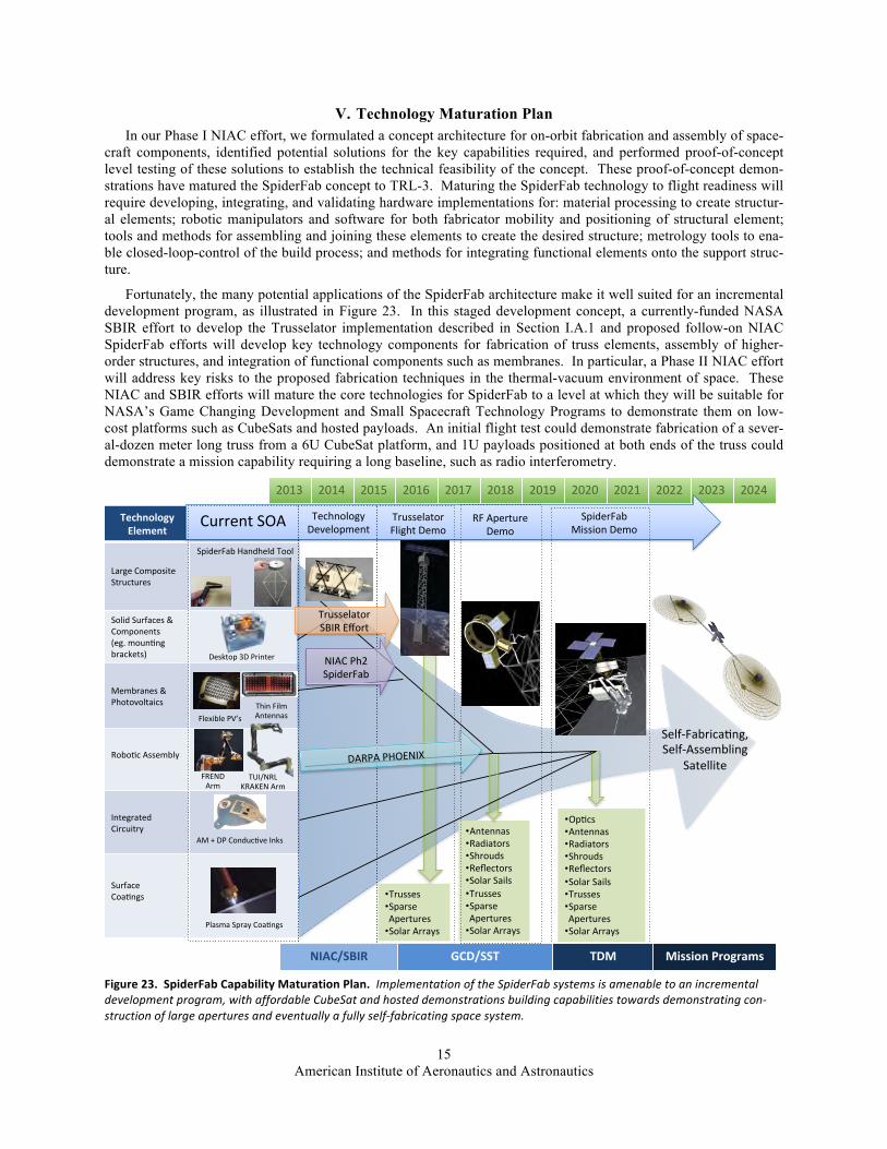
V. Technology Maturation Plan In our Phase I NIAC effort, we formulated a concept architecture for on-orbit fabrication and assembly of space-
craft components, identified potential solutions for the key capabilities required, and performed proof-of-concept level testing of these solutions to establish the technical feasibility of the concept. These proof-of-concept demon-strations have matured the SpiderFab concept to TRL-3. Maturing the SpiderFab technology to flight readiness will require developing, integrating, and validating hardware implementations for: material processing to create structur-al elements; robotic manipulators and software for both fabricator mobility and positioning of structural element; tools and methods for assembling and joining these elements to create the desired structure; metrology tools to ena-ble closed-loop-control of the build process; and methods for integrating functional elements onto the support struc-ture.
Fortunately, the many potential applications of the SpiderFab architecture make it well suited for an incremental development program, as illustrated in Figure 23. In this staged development concept, a currently-funded NASA SBIR effort to develop the Trusselator implementation described in Section I.A.1 and proposed follow-on NIAC SpiderFab efforts will develop key technology components for fabrication of truss elements, assembly of higher-order structures, and integration of functional components such as membranes. In particular, a Phase II NIAC effort will address key risks to the proposed fabrication techniques in the thermal-vacuum environment of space. These NIAC and SBIR efforts will mature the core technologies for SpiderFab to a level at which they will be suitable for NASA’s Game Changing Development and Small Spacecraft Technology Programs to demonstrate them on low-cost platforms such as CubeSats and hosted payloads. An initial flight test could demonstrate fabrication of a sever-al-dozen meter long truss from a 6U CubeSat platform, and 1U payloads positioned at both ends of the truss could demonstrate a mission capability requiring a long baseline, such as radio interferometry.
Figure 23. SpiderFab Capability Maturation Plan. Implementation of the SpiderFab systems is amenable to an incremental development program, with affordable CubeSat and hosted demonstrations building capabilities towards demonstrating con-‐struction of large apertures and eventually a fully self-‐fabricating space system.
2013% 2014% 2015% 2016% 2017% 2018% 2019% 2020% 2021% 2022% 2023% 2024%
Technology*Element*
Large%Composite%Structures%
SpiderFab%Handheld%Tool%
Solid%Surfaces%&%Components%(eg.%mounGng%brackets)%
Membranes%&%Photovoltaics%
RoboGc%Assembly%%
Integrated%Circuitry%
Surface%CoaGngs%%
Current%SOA%
Flexible%PV’s%
FREND%Arm%
• Trusses%• Sparse%Apertures%• Solar%Arrays%
• Antennas%• Radiators%• Shrouds%• Reflectors%• Solar%Sails%• Trusses%• Sparse%Apertures%• Solar%Arrays%
• OpGcs%• Antennas%• Radiators%• Shrouds%• Reflectors%• Solar%Sails%• Trusses%• Sparse%Apertures%• Solar%Arrays%
RF%Aperture%Demo%
providing an analog voltage proportional to the acceleration of the insert for all three dimensions. A single 3V power pin and ground were also included and a ground plane was painted behind the circuit to improve RF performance. The microcontrollers for the magnetometer and the rolling dice were programmed in C while the microcontroller for the helmet insert was coded in assembly. Each included non-volatile memory in order to store the program with no additional configuration chips required. The software for each begins by configuring the analog to digital converter and then initiates an endless loop, which repeatedly measures, digitizes, and stores each analog voltage received from the accelerometer (helmet insert and dice), or the magnetic Hall Effect sensors (magnetometer). In the case of the magnetometer and rolling dice, each loop used various mathematical equations to manipulate the input voltages and effectively display the necessary outputs. In the case of the magnetometer, the LEDs around the circumference of the top surface will light correlating to the direction of the magnetic field. Depending on the magnitude of the magnetic field, one, two or three of our magnitude LEDs will light. Regarding the dice, each LED on the top surface will light after the microcontroller recognizes that movement has ceased and determines orientation. For the helmet sensor, a 72 bit digital word is formed consisting of the transmitter serial number (used for device identification at the receiver), function codes, and the three acceleration values (voltages), which
correspond to the three axes. The transmitter then uses Amplitude Shift Keying (ASK) to modulate a 315MHz carrier signal and transmit the 72 bit word along with framing pulses for synchronization.
The microcontroller for the helmet insert receiver was also programmed in assembly language. The basic operation of the receiver program is to validate incoming transmissions by timing the framing pulses, verifying function codes in the transmission, and reading acceleration values from the 72 bit word received. The receiver can be configured via software to constantly output the acceleration values to a binary LED display, output acceleration values to the display only if they exceed a programmed threshold, or output the values to an RS232 serial port for use by an external application.
Future Work Several improvements are necessary to automate the steps in this proposed design process by converting the output of more traditional electronics PCB CAD. One of these improvements is the ability to project a circuit design onto a multi-curved surface. The capability does not yet exist in the currently implemented CAD software that does not distort the soon-to-be three-dimensional shape of our circuit. Inclusion of this feature will greatly reduce the amount of time spent between circuit design and three-dimensional circuit conversion. This work
(a)
(b) (c)
Fig. 7 – Completed helmet insert (a), magnetometer (b) and rolling dice (c).
(a) (b)
(c) (d)
Fig. 6 – Completed models of our helmet insert (a), magnetometer (b), rolling dice (c) and floating
sensor (d).
AM%+%DP%ConducGve%Inks%
Desktop%3D%Printer%
SelfZFabricaGng,%%SelfZAssembling%
Satellite%TUI/NRL%
KRAKEN%Arm%
Thin%Film%Antennas%
Plasma%Spray%CoaGngs%
10%
Trusselator%Flight%Demo%
SpiderFab%Mission%Demo%
Trusselator%SBIR%Effort%
NIAC%Ph2%SpiderFab%
DARPA%PHOENIX%
NIAC/SBIR* GCD/SST* TDM* Mission*Programs*
Technology%Development%

American Institute of Aeronautics and Astronautics
16
A follow-on mission flown as a secondary payload on an upper stage or other suitable platform could in-tegrate robotic assembly techniques developed by DARPA's Phoenix program to demonstrate fabrication and assembly of a higher-order structure to support a functional membrane. This second mission could demonstrate construction of a large-area spacecraft component, such as a 30x30m reflectarray, as illus-trated in Figure 24. With these fundamental capabili-ties matured to high TRL, we can then implement a full "SpiderFab Bot" construction system, integrating additional additive manufacturing techniques for digi-tal printing of circuitry and application of specialized coatings. We will demonstrate this system by fabri-cating a very large, complex spacecraft component, such as an Arecibo-sized antenna reflector, and inte-grating it with a host spacecraft to enable applications such as high-bandwidth communications with Mars and asteroid missions. This third demonstration would establish the SpiderFab capability at TRL 7+, readying it for infusion into the critical path of NASA Science and Exploration missions. Moreover, by ac-complishing flight validation of a re-usable space system fabrication process, rather than just a space system prod-uct, this development and demonstration program would enable a wide variety of future missions to be deployed with lower NRE cost and lower technical risk.
VI. Conclusion The SpiderFab effort has investigated the value proposition and technical feasibility of radically changing the way we build and deploy spacecraft by enabling space systems to fabricate and integrate key components on-orbit. We began by developing an architecture for a SpiderFab system, identifying the key capabilities required to fabricate large spacecraft components on-orbit, and developed two concept implementations of this architecture, one special-ized for fabricating support trusses for large solar arrays, and the second a more flexible robotic system capable of fabricating many different spacecraft components, such as antenna reflectors and optical occulters. We then per-formed several analyses to evaluate the value proposition for on-orbit fabrication of spacecraft components, and in each case we found that the dramatic improvements in structural performance and packing efficiency enabled by on-orbit fabrication can provide order-of-magnitude improvements in key system metrics. To establish the technical feasibility, we identified methods for combining several additive manufacturing technologies with robotic assembly technologies, metrology sensors, and thermal control techniques to provide the capabilities required to implement a SpiderFab system. We performed lab-based, proof-of-concept level testing of these approaches, in each case demonstrating that the proposed solutions are feasible, and establishing the SpiderFab architecture at TRL-3. Fur-ther maturation of SpiderFab to mission-readiness is well-suited to an incremental development program. A pair of initial low-cost flight demonstrations can validate key capabilities and establish mission-readiness for modest appli-cations, such as long-baseline interferometry. These affordable small demonstrations will prepare the technology for full-scale demonstration in construction of more ambitious systems, such as an Arecibo-scale antenna reflector. This demonstration mission will unlock the full game-changing potential of the SpiderFab architecture by flight qualifying and validating an on-orbit fabrication and integration process that can be re-used many times to reduce the life-cycle cost and increase power, bandwidth, resolution, and sensitivity for a wide range of NASA Science and Exploration missions.
VII. Acknowledgments This work was supported by NASA Innovative Advanced Concepts (NIAC) Grant NNX12AR13G.
Figure 24. Concept for demonstration of on-‐orbit construction of a large planar RF aperture. SpiderFab can be validated on affordable secondary payload platforms prior to use in opera-‐tional missions.

American Institute of Aeronautics and Astronautics
17
References
1. Mikulas, M.M., et al., "Truss Performance and Packaging Metrics," NASA Technical Document
20060008916. 2. Murphey, T.W., Hinkle, J.D., "Some Performance Trends in Hierarchical Truss Structures," AIAA-‐2-‐-‐3-‐
1903. 3. Cash, W., et al., "Astrophysics Strategic Mission Concept Study: The New Worlds Observer," 24 April
2009. 4. Cash, W., personal commun., 4Feb2013. 5. Data extracted from DARPA/TTO Phoenix Program Industry Day Briefing, 11Feb13.