spherical pressure vessels university of …dtic.mil/dtic/tr/fulltext/u2/a236266.pdfuniversity of...
TRANSCRIPT

WRDC-TR-90-4141 AD-A236 266
STRENGTH ANALYSIS AND DESIGN OFMULTILAYERED THICK COMPOSITESPHERICAL PRESSURE VESSELS
Ajt K. RoyUniversity of Dayton Research Institute300 College Park AvenueDayton, OH 45469-0168
MARCH 1991
Final Report for the Period May 1990 - August 1990
Approved for public release; distribution unlimited.
DTICfaF 1-ECT K
U UN 04 199 11u
MATERIALS LABORATORYWRIGHT LABORATORYAIR FORCE SYSTEMS COMMANDWRIGHT-PATTERSON AIR FORCE BASE, OH 45433-6533
91-00903II II 1I 111 III3 0 4I
91a O 054

NOTICE
WHEN GOVERNMENT DRAWINGS, SPECIFICATIONS, OR OTHER DATA ARE USED FOR ANYPURPOSE OTHER THAN IN CONNECTION WITH A DEFINITELY GOVERNMENT-RELATEDPROCUREMENT, THE UNITED STATES GOVERNMENT INCURS NO RESPONSIBILITY OR ANYOBLIGATION WHATSOEVER. THE FACT THAT THE GOVERNMENT MAY HAVE FORMULATED OR INANY WAY SUPPUED THE SAID DRAWINGS, SPECIFICATIONS, OR OTHER DATA, IS NOT TOBE REGARDED BY IMPUCATION, OR OTHERWISE IN ANY MANNER CONSTRUED, AS LICENSINGTHE HOLDER, OR ANY OTHER PERSON OR CORPORATION; OR AS CONVEYING ANY RIGHTS ORPERMISSION TO MANUFACTURE, USE, OR SELL ANY PATENTED INVENTION THAT MAY IN ANYWAY BE RELATED THERETO.
THIS REPORT HAS BEEN REVIEWED BY THE OFFICE OF PUBUC AFFAIRS (ASOIPA)AND IS RELEASABLE TO THE NATIONAL TECHNICAL INFORMATION SERVICE (NTIS). ATNTIS IT WILL BE AVAILABLE TO THE GENERAL PUBLIC INCLUDING FOREIGN NATIONS.
THIS TECHNICAL REPORT HAS BEEN REVIEWED AND IS APPROVED FOR PUBLICATION.
KENNETH M. J SONProject Engineer CHARLES E. BRO I Chief -
Structural Materials Branch Structural Materials BranchNonmetallic Materials Division Nonmetallic Materials Division
FOR THE COMMANDER
MERRILL L. MINGES, SESDirectorNonmetallic Materials Division
IF YOUR ADDRESS HAS CHANGED, IF YOU WISH TO BE REMOVED FROM OUR MAILINGLIST, OR IF THE ADDRESSEE IS NO LONGER EMPLOYED BY YOUR ORGANIZATION PLEASENOTIFY WL/,LBC WRIGHT-PATTERSON AFB, OH 45433-. 6 TO HELP MAINTAINA CURRENT MAILING LIST.
COPIES OF THIS REPORT SHOULD NOT BE RETURNED UNLESS RETURN IS REQUIRED BYSECURITY CONSIDERATIONS, CONTRACTUAL OBLIGATIONS, OR NOTICE ON A SPECIFICDOCUMENT.

Form Approved
REPORT DOCUMENTATION PAGE OMB No. o4-018Public reOom,rig burden for this collection of information is estimated to average I hour Per response. including the time for realeWng instuctro hi. rifng existing data sources.gathering and maintaining the data needed, and complet.ng and reuevmn 9 the collectDon of information send comments regarding this burden estimate or any other asect of thiscollection of information, Including suggestions for reducng this burden to Washington Headquarters Services. Directorate for information Operations and Reports. 1215 JeffersonDavis Highway. Suite 1204. Arlington. VA 22202-4302. and to the Office of Management and Budget. Paperworh Reduction Project (0704-018). Washington. DC 20S03
1. AGENCY USE ONLY (Leave blank) 12. REPORT DATE 3. REPORT TYPE AND DATES COVERED
March 1991 I Final Report - May-August 19904. TITLE AND SUBTITLE S. FUNDING NUMBERS
STRENGTH ANALYSIS AND DESIGN OF MULTILAYERED THICK F33615-87-C-5239COMPOSITE SPHERICAL PRESSURE VESSELS Program Element 62102F
6. AUTHOR(S) Project No. 2419Task No. 02
Ajit K. Roy Work Unit Accession #25
7. PERFORMING ORGANIZATION NAME(S) AND ADDRESS(ES) 8. PERFORMING ORGANIZATION
University of Dayton Research Institute REPORT NUMBER
300 College Park Avenue UDR-TR-90-128Dayton, OH 45469-0168
9. SPONSORING/ MONITORING AGENCY NAME(S) AND ADDRESS(ES) 10. SPONSORING/ MONITORINGMaterials Laboratory (WL/MLBC) AGENCY REPORT NUMBER
Wright Laboratory (K. Johnson, 255-9073) WRDC-TR-90-4141Air Force Systems CommandWright-Patterson AFB, OH 45433-6533
11. SUPPLEMENTARY NOTES
12a. DISTRIBUTION/AVAILABILITY STATEMENT 12b. DISTRIBUTION CODE
Approved for public release; distribution unlimited.
13. ABSTRACT (Maximum 200 words)A design study of a multilayered spherical composite pressure vessel is presented.
Each layer of the vessel is composed of quasi-isotropic layups of composite plies.For the stress analysis, however, each layer is assumed to be homogeneous whose
IL three-dimensional properties are equivalent to that of the quasi-isotropic plies.The linear theory of elasticity is employed so that the analysis is not limited toany thickness of the vessel. For the strength analysis the Tsai-Wu failure criter-ion is used. Using the ply constitutive law and lamination angle, the ply stressesand strains are determined from the layer stresses and strains. Then the failurecriterion is used for each ply. It is found that the first-ply-failure (FPF) con-trols the final failure.The objective of this study is to design a spherical vessel with an acceptable
safety factor to operate at 200 MPa internal pressure. In view of the winding andmanufacturing difficulties, a design restriction of b/a < 1.25 was set for thisdesign. However a two-layered hybrid sphere of b/a=1.25-(b: outer radius, a: innerradius) with T300/5208 and IM6/epoxy outside is considered to be an acceptabledesign. The failure test data of two vessels are also reDorted in this Rtudy.
14. SUBJECT TERMS 15. NUMBER OF PAGESlaminated sphere, graphite/epoxy, thick, design, multilayered, _5CCOD_
burst pressure, failure pressure 16. PRICE CODE
17. SECURITY CLASSIFICATION 18. SECURITY CLASSIFICATION 19, SECURITY CLASSIFICATION 20. LIMITATION OF ABSTRACTOF REPORT OF THIS PAGE OF ABSTRACTUnclassified Unclassified Unclassified UL
NSN 7540-01-280-5500 Standard Form 298 (Rev 2-89)Prp%(,r,tyid by ANSI S d 139-15290-102
FOREWORD
The work reported herein was performed at Ecole National Superieure des Mines deSaint-Etienne (EMSE), France, under a collaborative program between the WL MaterialsLaboratory and EMSE. This work was performed by Ajit K. Roy of the University of DaytonResearch Institute under Contract No. F33615-87-C-5239 for the period from May 1990 toAugust 1990.
ACKNOWLEDGEMENT
The author wishes to thank Professor Georges Verchery of EMSE and Dr. ThierryMassard of Commissariat a l'Energie Atomique (CEA), France for their technical assistanceand encouragement.
Acoesson l "
ISTIS G7 A& I01IC TAIn 0Unaniou mced C-Just Ig'cat ion
' sf. ctIO
Distribution/
Availability Codes
Avail and/or
Dist Spocil

TABLE OF CONTENTS
SECTION PAGE
1. INTRODUCTION 1
2. EQUATIONS FOR STRESSES AND STRAINS FOR MULTI-LAYER SPHERE 2
3. STRESSES AND STRAINS FOR SINGLE LAYER SPHERE 5
4. FAILURE CRITERION FOR THREE-DIMENSIONALLAMINATES 5
5. STRENGTH ANALYSIS OF SPHERES 6
6. BURST AND COLLAPSE PRESSURE OF SPHERES MADEOF ONE MATERIAL 8
7. BURST AND COLLAPSE PRESSURE OF SPHERES MADEOF TWO MATERIALS 9
8. CONCLUSIONS 11
REFERENCES 13
APPENDIX A: Method of Predicting Three-DimensionalEffective Moduli of Laminates 14
APPENDIX B: Instructions for Executing the FORTRANProgram "Sphere" 23
V

LIST OF ILLUSTRATIONS
FIGURE PAGE
1. Coordinate system
2. Cross section of the sphere and interlayer tractions, qi, used in the
analysis 3
3. 3-D quadratic failure criterion for a transversely isotropic material 6
4. Relations between ply stress and laminate stress in a 3-D thicklaminate 7
5. The best-fit interaction term in the isotropic plane based on themeasured uniaxial compressive strength 7
6. The burst pressures of two graphite-epoxy composite spheres asfunctions of the ratios of radii 9
7. Comparison of the predicted burst pressure with the tested data 10
8. The burst pressure of two hybrid spheres as functions of the layerthickness 11
9. Configuration of the laminated ring and its equivalent homogeneousring subjected to equal hydrostatic pressure on the inner and outersurface 15
10. Configuration of the laminated beam and its equivalent homogeneousbeam under end transverse load 16
11. Configuration of the laminated beam and its equivalent homogeneousbeam under uniformly distributed load on the top and bottom surface 19
vi

1. Introduction
Fiber reinforced composites have been used for about two decades for improving the burst (dueto internal pressure) and collapse pressure (due to external pressure) of spherical pressure vessels
[1-31. Although several reinforcing patterns had been tried in the past, for example radial
filament reinforcement [3], the accepted technology for reinforcing spherical vessels has emergedto be the quasi-isotropic lay-ups in the 0-0 plane (0: colatitude, : azimuth) (Figure 1).
z
r 0r
0
X
Figure 1. Coordinate System
Gerstle [41 has reported the stress and strength analysis of single-layered fiber reinforcedspherical vessels with elastic-ideally plastic bladder. In his work the layer of a vessel is
considered to be composed of quasi-isotropic lay-ups of one type of material. Gerstle has found
that the burst pressure of a single-layered vessel is limited by the radial compressive strength of
the vessel. The radial compressive strength of these vessels, incidentally, is related to the
stiffness and transverse compressive strength of the laminae used in the lay-ups. Thus onelogical way of improving the failure pressure is to make hybrid vessels where an optimal use of
the stiffnesses and strengths of the layers is expected to improve the failure pressure. Gerstle 15]has then presented a similar work for two-layered hybrid spherical vessels and has shown a way
to use the stiffnesses and strengths of the two hybrid layers in improving the burst pressure over
that of a single-layered vessel. The work presented here is in a way an extension of Gerstle's
work and is applicable to any number of layers.

2. Equations for Stresses and Strains for Multilayer Spheres
The effective properties of the layers of a spherical vessel with quasi-isotropic lay-ups are
transversely isotropic with isotropy in the the 0- plane (Figure 1). The vessel is considered
spherically symmetric. The stress-strain relations of the i-th layer of the vessel reduce to [61
i (i) + 2 C(') (i)=o o (1)
W i) ( W 4) W( i) (i)\ (2)-- Cro +1 4-[0(. Opol- 0 (2)
8 r rO 88(3
4i) _ __ (i) U (i)d7 - r -' ='0 (5)
Here CiP), SiP), (i, = r, e, 0) are the elements of the three-dimensional effective stiffness and
compliance matrices of the i-th layer respectively. A method of determining the three-
dimensional effective stiffnesses and compliances of a laminate is given in reference [7] and is
summarized in Appendix A. If the sphere is subjected to both internal and external pressure,
then the boundary conditions are
when r = a err (I) = -p (the negative sign is because of the compressive pressure) (6)
when r = b crrn) = -q (the negative sign is because of the compressive pressure) (7)
At the interface between two adjacent layers the following conditions must be satisfied
at the interface r = ai crr i) = r (i+1) (8)
ur/i) = u/(i+1) (9)
If we express the stresses, strains, and displacement in terms of the interlayer normal tractions,
qi, (Figure 2)
2

aq~ qi qn-i qn
Figure 2. Cross section of the sphere and interlayer tractions, qj, used in the analysis.
then the expressions for stresses, strains, and displacement of the sphere are:
- ,[ ni+ 2 r j3ajnjj~1-C7i [2qi c ai r (10)
190) - I _____I_________ 1
2 rr C6 +rO ~ r ,+
-C2nL (n+LcX}-2c(nj+ C 1 q-~.2(1
q' (12)
=i ~ 2- qj) 3_( 1 -)(qi-l -qicc4-1) 3
F(jj)q.IC 3 3i+
40 2f qic' f-qj (Lj_)ni 2 j -1i 'LnL~)2C) r 1 (01 2 rO1 (14)
i~i 143
e (i) (=' 0 (15)
U i4') = a___ _Ic5-q-A___. qi-l-qic_-_ i+
r 2n, ri a) ~ i'()r
1-ci n'[ni-2L)C(')+2cio r" (nlc,(r)_-2 C:;c [r
£2 rO (16)
where
ci= ni 1+8 00 0qC rO
Incidentally, when r a equation (10) becomes
o") (r = ao = a) = -qo = -p (inside pressure) (17)
and when r = b equation (10) again reduces to
o(n) (r = an = b) = -qn = -q (outside pressure) (18)
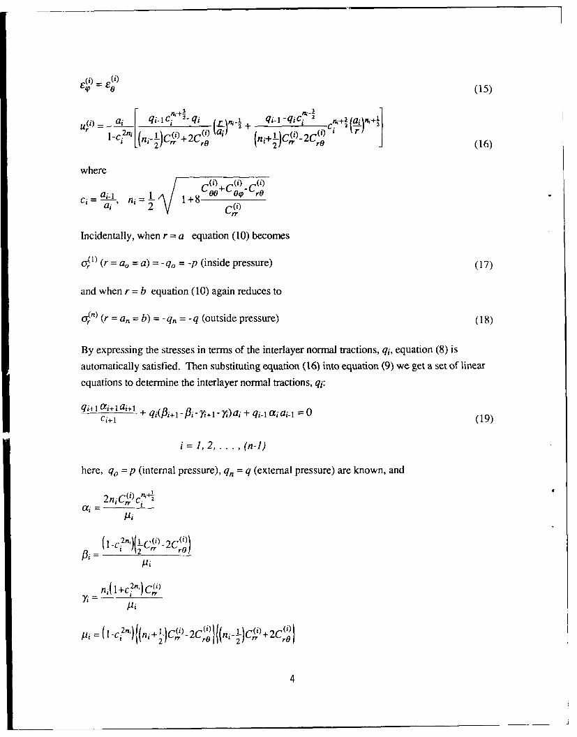
By expressing the stresses in terms of the interlayer normal tractions, qj, equation (8) is
automatically satisfied. Then substituting equation (16) into equation (9) we get a set of linear
equations to determine the interlayer normal tractions, qi:
qi+ I 0i+1ai+ + qj(Pj+l-Pi - +1- )ai + qi-1 aiai-I = 0ci+i (19)
i =1, 2.. . , (n-l)
here, qo = p (internal pressure), qn = q (external pressure) are known, and
2niC(y) c f
a i -I
Ii
ni (1 +C2ni) C2(ri' i
-(I _C7") (ni+-L)C4P,)2C(l(ni-J-)C')+ 2C(')
4

The interlayer normal tractions, (qi, i = 1, .... , n-i), are known by solving equation (19). Then
substituting the values of qi in equations (10-16), the stresses, strains, and displacement for all
layers are determined.
3. Stresses and Strains for Single Layer Spheres
If there is only one material for the spherical shell, super and subscripts in the equations above
assume only one value; i.e., i = 1; then in the inside radius, r = ao = a; and on the outside radius,
r = a, = b. We can define the ratios of the radii as:
= ao - aa1 b
All equations in the previous section are simplified for the case of one layer of material which can
also represent a homogenized laminated shell.
4. Failure Criterion for Three-Dimensional Laminates
Failure criteria for a three-dimensional body can be easily written down in terms of the most
general quadratic form. There will be a maximum of 15 strength parameters.
A transversely isotropic material is a reasonable representation of a unidirectional composite ply if
the diameter of the fiber is small relative to the thickness of the ply and there are many fibers
randomly distributed in the ply. With this symmetry, the number of strength parameters can be
reduced to eight. If we can further invoke the identity between tension-compression stresses and
pure shear oriented 45-degrees from the former stresses, this additional relation further reduces the
strength parameters in a 3-D transversely isotropic materials to seven.
5

* Fijoj+Fiaj = 1, for 3-D contracted notation: 0 q = oUz, Ur = Uzx, Us= Ox9Fxx2 2 2 + 2Fqqa2 +Frr a 2 +Fsso2 No. parameters_,
+2Fxyaxx +2 Fxz Uxcrz+ 2 Fzcz cTaz+FxOx+FycUy+Fzcyz+Fqaq+Frur+Fs as = 1 - 15
" From symmetry: Fyy = Fzz, Frr = Fss, Fxy = Fxz, FY Fz, Fq = Fr = Fs = 0 - B
FxxU 2 + Fy(o+ Cr )+ FqqO2 + Fss(o 2 2
,2Fxycx(ay+az)+2Fyza az+FxGx+Fy(oy~oz) = 1I
" From transverse isotropy: cr = -az = Q, other oi = 0 7
Fyy(2Q 2)-2FyzQ2 = 1, orQ2 = I or Q=' 2(Fy- Fyz) ' /2( 1 - Fyz)*
where Fyz = F*,Y Fzz FZ Fz =
Figure 3. 3-D quadratic failure criterion for a transversely isotropic material
Thus the difference between 2- and 3-D quadratic failure criteria for a unidirectional ply is by only
one additional strength parameter. The reduction in the number of strength parameters from 15 to
seven is illustrated in Figure 3.
5. Strength Ar lysis of Spheres
Stress analysis of a spherical shell in 3-D is similar to that for 2-D provided appropriate elastic
moduli and stress-strain relations are used. 3-D analysis will of course require 3-D moduli and 3-D stress-strain relations. This is illustrated in Figure 4 where over bars represent the average stress
or strain of the 3-D thick laminate. The relation between laminate stress and ply stress is
determined with the knowledge of the laminate compliance and ply stiffness, both in 3-D.
6
{} =[3]{U}, where [9] is the 3-D laminate compliance
(a) [C]{}, where [C] is the 3-D ply stiffness
[F1jjcuj]R2 +[Fjaj]R- 1 = 0,
where Fij, Fj are 3-D strength parameters
Assuming unidirectional plies are transversely isotropic:FxxCx +Fyy(2 + 2F*o~ c or +3a2)+ 2F x< o
+Fss(j2+j2r)+Fx (+ o =
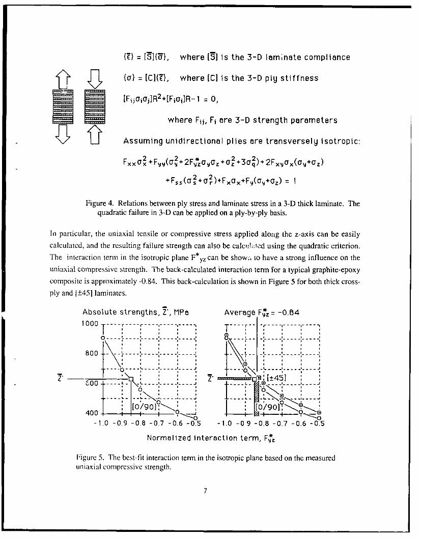
Figure 4. Relations between ply stress and laminate stress in a 3-D thick laminate. Thequadratic failure in 3-D can be applied on a ply-by-ply basis.
In particular, the uniaxial tensile or compressive stress applied along the z-axis can be easilycalculated, and the resulting failure strength can also be calcihttcd using the quadratic criterion.The interaction term in the isotropic plane F * yz can be show., to have a strong influence on theuniaxial compressive strength. The back-calculated interaction term for a typical graphite-epoxycomposite is approximately -0.84. This back-calculation is shown in Figure 5 for both thick cross-ply and 1±45] laminates.
Absolute strengths, Z, MPa Average F*z -0.84
1000 ---
800 - I I '
---- ---- ---- -- \ I - --
. . .. \ . .
T',, ~~21 [t451 " ..I*II". 400 --------- -. . . -' -......... - D -+45] ,0 M' I0
00400- t "-0 ' o' '
-1.0 -0.9 -0.8 -0.7 -0.6 -0.5 -1.0 -0 9 -0.8 -0.7 -0.6 -0.5
Normalized interaction term, F*=
Figure 5. The best-fit interaction term in the isotropic plane based on the measureduniaxial compressive strength.
7

It is seen that the quadratic failure criterion required a highly coupled relation. The maximum
stress or maximum strain criterion assumed that interaction between failure modes does not exist.
Based on the test results shown in Figure 5, the predicted maximum compressive strength would
be the same as the transverse compressive strength in a unidirectional ply. The value for most
graphite-epoxy composites would be in the range of 200 MPa. Thus an error of 300 percent is the
result of ignoring failure mode interactions. We therefore believe that the quadratic criterion is
flexible in taking into account such mode interactions; while the maximum stress or maximum
strain criterion is rigidly defined and does not recognize the interactions.
6. Burst and Collapse Pressure of Spheres Made of One Material
The burst and collapse pressures of a thick spherical shell under internal and external pressures
based on strength can be derived using the stress analysis for thick shells coupled with appropriate
failure criteria. In the present study, it is assumed that the shell failure is controlled by strength,not
by buckling. It is further assumed that the shell consists of homogeneous, quasi-isotropic material
with 3-D elastic constants listed in Appendix A.
The predicted burst pressures for typical composite materials are shown in Figure 6. From the
equations of stress and strain, it is observed that they are dependent on the ratio of the outside to
inside radii, not on their absolute values. The displacements on the other hand are functions of the
absolute radii.
8

Burst presssure, MPa
300 i.. ... T3o/52o8
I I I I I I I I I250 ---- - - - -- - -- - - - - -- -..... ... . . ."------ ... ---- .
* I I I I I I I I* ~ 1r16/epoxy200---T---------------.T I
15 0 ---- ----
I O0 ... . L ... ... . .. >.. > u OD failure "
SO ....o -;' - - . ..* • I D failure* I I I I I i
0I a I "I
1.0 1.1 1.2 1.3 1.4 1.5
Outside RadiusInside Radius
Figure 6. The burst pressures of two graphite-epoxy composite spheres as functions ofthe ratios of radii.
Open symbols for each material are shown for failure on the outside diameter and solid symbols onthe inside. For thin shells failure occurs on the outside; for thick shells failure occurs on theinside. Both materials reach some asymptotic strength level, but their functional dependences on
the ratio of radii are different. Below a ratio of 1.35, IM6 has higher burst pressure; above thisratio, T300 becomes higher. It is therefore not possible to guess what material would be stronger
unless a calculation is made first.
7. Burst Pressure of Hybrid Spheres Made of Two Materials
One of the objectives of this work is to design a composite sphere to operate at 200 MPa. For the
initial design a safety factor of 1.5 was considered. Thus the design of a sphere that couldwithstand a maximum pressure of 300 MPa was considered to be a safe design. It was initially
inferred from Figure 6 that a sphere made with T300/5208 composite of b/a=1.5 could take the
pressure close to 300 MPa. As a part of a demonstration of the design, a T300/epoxy sphere ofinner diameter of 240 mm and b/a=1.5 was constructed. The sphere, however, failed prematurely.
A close examination of the video photographs of the test indicated that the failure initiated at the
interface between the liner nozzle and the composites. For this sphere of b/a=1.5, the thickness of
9
the composite was approximately 60 mm. Relating to the complex winding pattern involved in the
vicinity of the liner nozzle of the sphere, the manufacturer (Courtaulds Advanced Materials,
France) pointed out the difficulty in maintaining a good structural integrity of the interface between
the liner nozzle and the composites for such a thickness of the sphere. The above premature failure
may thus be attributed to the poor interface between the nozzle and composites. Incidentally, two
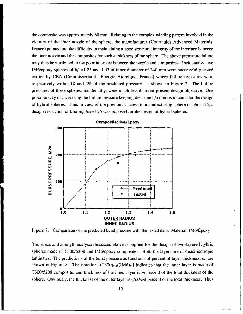
IM6/epoxy spheres of b/a=1.25 and 1.33 of inner diameter of 240 mm were successfully tested
earlier by CEA (Commissariat A rEnergie Atomique, France) where failure pressures were
respectively within 10 and 4% of the predicted pressure- as shown in Figure 7. The failure
pressures of these spheres, incidentally, were much less than our present design objective. One
possible way of L:creasing the failure pressure keeping the same b/a ratio is to consider the design
of hybrid spheres. Thus in view of the previous success in manufacturing sphere of b/a=1.25, a
design restriction of limiting b/a=1.25 was imposed for the design of hybrid spheres.
Composite: IM61Epoxy300
2 0 .................................. ................................... .. .... .. ....... .. ......... . ...................... .................................* 200
I - 1 0 0 .... ...................... ...... ................................. ................................. .................................. i..................................
(/7Predicted
* • Tested
1.0 1.1 1.2 1.3 1.4 1.5
OUTER RADIUSINNER RADIUS
Figure 7. Comparison of the predicted burst pressure with the tested data. Material: IM6/Epoxy
The stress and strength analysis discussed above is applied for the design of two-layered hybrid
spheres made of T300/5208 and IM6/epoxy composites. Both the layers are of quasi-isotropic
laminates. The predictions of the burst pressure as functions of percent of layer thickness, m, are
shown in Figure 8. The notation [(T300)m/(IM6)nl indicates that the inner layer is made of
T300/5208 composite, and thickness of the inner layer is m percent of the total thickness of the
sphere. Obviously, the thickness of the outer layer is (100-m) percent of the total thickness. Thus
10

the sum of m and n becomes 100. When either m or n becomes zero or 100, the sphere is no
longer a hybrid sphere but rather a sphere of one material. It is obvious from the figure that a
hybrid sphere with T300 inside and IM6 outside yields a higher burst pressure than a sphere with
reversed order of the layers. It is also noticed from the figure that, for the hybrid sphere with T300
inside, if the thickness of either of the layers is varied between 20 and 80% of the total thickness,
the variation of the burst pressure is limited to within only 2.5% of 240 MPa. Thus within the
range of 20 to 80% of the layer thickness, any small manufacturing error in the layer thickness will
hardly alter the expected burst pressure.
b/a= 1.25, Quasi-isotropic280 .. . . . .
© 240 .
01- 200 ... 4- I M6
L160
IM612 0 . ...~~~ ~~~. ...................... .......... .... ......... ....................... i ................. - T 5 0 0
C.. [(IM6)m/(T30O)n]
L
m+n=10
0 20 40 60 80 100
LAYER THICKNESS PERCENT, mFigure 8. The burst pressure of two hybrid spheres as functions of the layer thickness.
8. Conclusions
We have presented a procedure to determine the stress, strain, and ultimate internal and external
pressures of a homogenized, isotropic spherical shell of any thickness. It can be shown that the
membrane solution would correspond to the tangent of the burst pressure curves in Figure 6
above.
Comparable curves for other materials will require the 3-D elastic moduli and seven strength
parameters needed for the quadratic failure criterion. The collapse pressure of spherical shells
under external pressure can be determined precisely the same way. Only boundary conditions need
to be changed.
11

The required calculation can be easily programmed in a small computer. In fact, a Fortran programis written to perform the numerical analysis for multilayered (or hybrid) spheres. The instructions
for executing this code are given in appendix B.
12

References
(1) Lark, R.F., Filament-Wound Composite Vessel Materials Technology, Second International
Conference on Pressure Vessel Technology, Part 1, Design and Analysis, ASME, Oct.
1973, pp 573-580.
(2) Tauchert, T.R., Thermal Stresses in a Spherical Pressure Vessel Having Temperature-
Dependent, Transversely Isotropic, Elastic Properties, Advances in Engineering Science,
Vol. 2 (Proceedings of the 13th Annual Meeting of the Society of Engineering Science),
NASA CP-2001, Nov. 1976, pp 639-651.
(3) Bert, C.W., Analysis of Radial Filament-Reinforced Spherical Shells Under Deep
Submergence Conditions, Second International Conference on Pressure Vessel
Technology, Part 1, Design and Analysis, ASME, Oct. 1973, pp 529-534.
(4) Gerstle, F.P.Jr., Analysis of Filament-Reinforced Spherical Pressure Vessels, Composite
Materials: Testing and Design (Third Conference), ASTM STP 546, American Society of
Testing and Materials, 1974, pp 604-631.
(5) Gerstle, F.P.Jr., Thick-Walled Spherical Composite Pressure Vessels, appeared in
Composites in Pressure Vessels and Piping, edited by S.V. Kulkarni and C.V. Zweben,
ASME, PVP-PB-021, 1977, pp 69-87.
(6) Love, A.E.H., A Treatise on the Mathematical Theory of Elasticity, Dover Publications
(reprint of the fourth edition, 1927), 1944, Sections 110 and 114.
(7) Roy, AK. and S.W. Tsai, Three-Dimensional Effective Moduli of Orthotropic and
Symmetric Laminates, to appear in the Journal of Applied Mechanics.
(8) Tsai, S.W., Composites design, Fourth edition, Think composites, Dayton, 1988, Appendix B.
13

Appendix A
Method of Predicting Three-Dimensional Effective Moduli of Laminates:
The sphere is considered to be made of layers with quasi-isotropic lay-ups. The stress analysis is
performed by considering the three-dimensional effective moduli of each layer. The method ofpredicting an equivalent homogeneous effective moduli of a laminate is discussed in detail in
reference 171. Briefly, the method is based on matching the boundary displacements of thehomogeneous system with those of the laminated system of three interrelated boundary valueproblems (BVP). The BVP are: (a) ring subjected to equal hydrostatic pressure on both
surfaces, (b) cantilever beam under end transverse load, and (c) cantilever beam subjected touniformly distributed load on top and bottom surfaces. These interrelated BVP are selected to
predict the effective moduli for in-plane and bending mode of deformation. The analyses for
predicting the effective moduli are given below:
Problem 1. Ring with Hydrostatic Pressure
This problem is used to predict the interlaminar effective moduli of symmetric and orthotropic
laminates for in-plane extension. For a large value of the radius to thickness ratio, r/t (r: radius,
t: thickness), the deformation of the ring approximately represents the in-plane deformation. The
laminated ring and its equivalent homogeneous ring are subjected to equal hydrostatic pressure
on both inner and outer surface, p, as shown in Figure 9. The inner and outer displacements of
the homogeneous ring are matched with those of the laminated ring to obtain effective moduli ofthe laminate of the ring. The interlaminar effective elastic constants obtained from this problem
-o -O -0are E3, V3 1, and V3 2, where vij is the Poisson's ratio for Ei under aj. The superscript 'o' is usedto indicate that the elastic constants are associated with the in-plane deformation.
14

~2.8
i-3 , -.......
b) EQUIVALENT(~) AMINTED INGHOMOGENEOUS RING
Figure 9. Configuration of the laminated and its equivalent homogeneous ring subjected to equalhydrostatic pressure on the inner and outer surface.
The method of obtaining the radial displacement of the laminated composite ring, u'(r),
(Figure 9a) is given by Lekhnitskii (1968). The subscript Ti indicates the j-th layer of the
laminated ring. We do not find the necessity of repeating the procedure for obtaining the
expression of u'(r) in this report. The expression for the radial displacement of the equivalent
homogeneous ring (whose effective moduli are to be determined, Wagure 9b) is similar to that of
any layer of the laminated ring; that is:
u(r)- p $nk 23 ((mk+l )( ~)'k- {(-kl~ l +
+ 1 kS 22 I(rnk+ -1 )k(-)'k"+( 1-mk-)kmk+(b)" 1 1r (1
b' / S- , a: inner radius, b: outer radius, and Si (i,j=2,3) are the elements
of the effective compliance matrix.
By equating the inner and outer displacements of the homogeneous ring with those of the
laminated ring, we get two nonlinear equations in k, $22, and $23 as follows:
apriklmk kI(1 k1iIV 0l $2( m~-m-)-2m-2 k)]-ul~a)= 0 (for r=a, i=l) (A2)
bp -S 2k(2mk+-m2k- 1)-S23( l-m2k)] -u"(b) = 0(frrbin)A3I -m2k [ 2 frrb ~)(3
15
The laminated ring is assumed to have n number of layers in equation (A3). Here S22 is
considered to be known from the laminated plate theory which seems to be a reasonable
assumption. Then S23, k, and hence S33 are solved from equations (A2) and (A3) by the
Newton-Raphson's technique. The laminate effective properties in terms of S22, S23, and S33
are:
o 1 -O S 2 33 S33 V32 2 (A4)
The constant '31 can similarly be obtained by rotating the laminate by 90' about the r-axis of the
ring (a 90 degree rotation brings the 1-axis of the laminate with the 0-direction of the ring). The
superscript 'o' is, again, to denote that the effective properties apply for in-plane deformation.
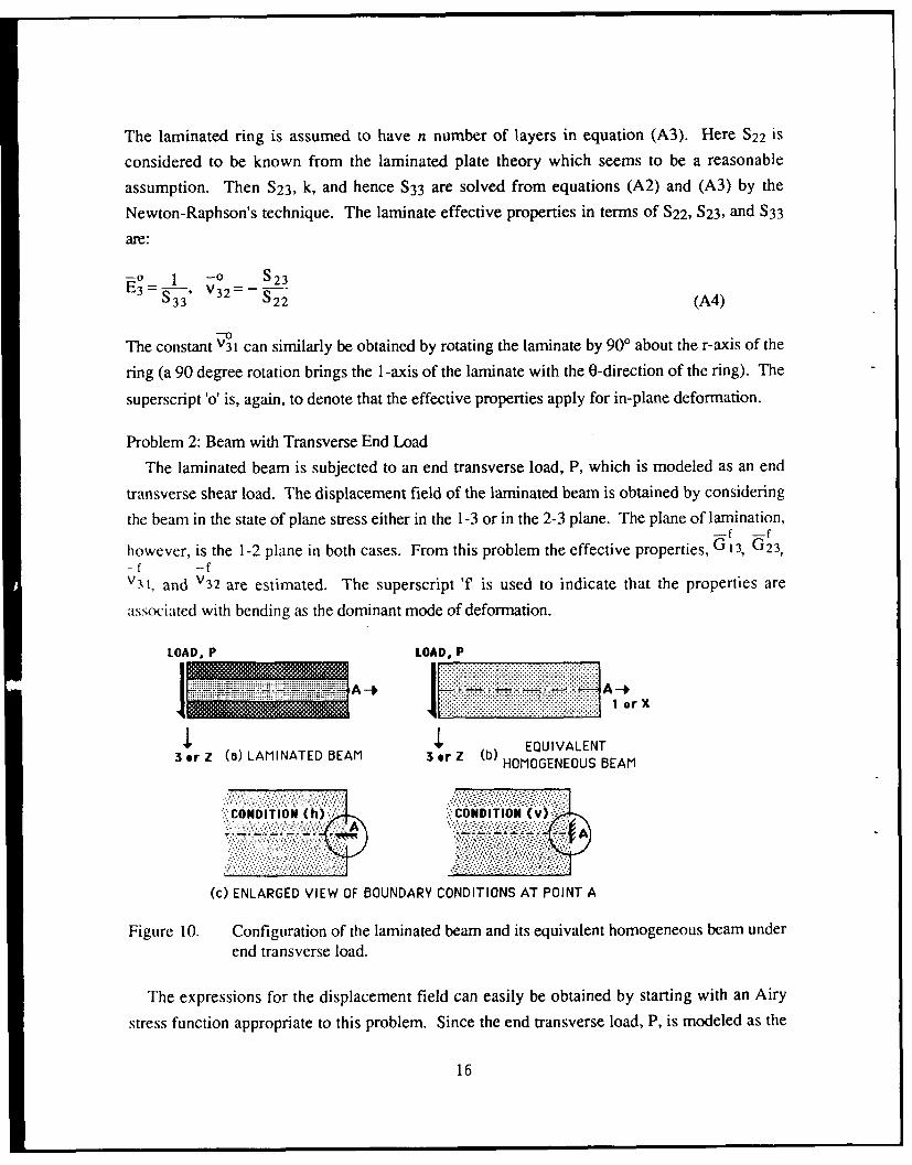
Problem 2: Beam with Transverse End Load
The laminated beam is subjected to an end transverse load, P, which is modeled as an end
transverse shear load. The displacement field of the laminated beam is obtained by considering
the beam in the state of plane stress either in the 1-3 or in the 2-3 plane. The plane of lamination,-f -f
however, is the 1-2 plane in both cases. From this problem the effective properties, G 13, G 23,-f -fv3 1, and V3 2 are estimated. The superscript 'f is used to indicate that the properties are
associated with bending as the dominant mode of deformation.
LOAD, P LOAD, P
or Z (a) LAMINATED BEAM 3or Z (b) HMGNOSBA........... ............... ................. ........... .... . ..... ....... . . .
. ... ................
CODTIN:h CONDITION (V),1
A A
.... ........................ ............... .............. .'...
(c) ENLARGED VIEW OF BOUNDARY CONDITIONS AT POINT A
Figure 10. Configuration of the laminated beam and its equivalent homogeneous beam underend transverse load.
The expressions for the displacement field can easily be obtained by starting with an Airy
stress function appropriate to this problem. Since the end transverse load, P, is modeled as the
16

transverse shear load, (see Figure 10), it is logical to assume that az is zero everywhere in the
beam. The Airy stress function, Fj(x,z), for a constituent orthotropic lamina of the above
problem for stresses in the (x-z or 1-3) plane, has the form
Fj(x,z) = Ajxz + Bjz 2 + CJxz2 +Djz 3 + Ejxz3 (A5)
where the constants, Aj, Bj, .. ., Ej are associated with the properties of the j-th lamina. After
using the linear stress-strain constitutive relations and the expressions for stresses in terms of the
above stress function, Fj(x,z), the displacement fields of the laminated beam, u (x,z) andw,(x,z), along the x and z directions respectively, are:
+xz) = Bjs2Z () ) 3
+DjS11 x z +EjSllx+Qjz+RJ (A6)
SAjS(j ) -BjS13xz+CjSO) --X +(J)XZ 2 "
" +IDj[S( z2 S(J)3 11 13 (A7)
The constants Aj, Bj, .... Ej, Mj, Qj, Rj, for the j-th lamina, are determined from the contact
conditions at the interface of each lamina, boundary traction, P, and the boundary conditions at
the support end, x=L. Here Sij(k) (i,j = 1,3,5) are the elements of the compliance matrix of the
k-th lamina.Following a similar procedure for equations (A6) and (A7), the expressions for the
displacement fields, uh(x,z) and wh(x,z), for the equivalent homogeneous beam (Figure 10b) forplane stress in (1-3) or (x-z) plane, keeping a horizontal element at point A (Figure 10) fixed, are:
uh(xz) = [6S 1 (L2-x2)z+2S1 3z3+S 55(2z3 - 3H2z)
bH3 L 2 (A)
wh(xz) PHl [2Sn (x3-3L-2x+2L3) - 6SI 3 xz2]
where, L,b, and H are the length, width, and depth of both beams, respectively. The effective
compliance matrix for the homogeneous beam, Sij (ij=1,3,5), is to be determined by matching
the boundary displacement of the homogeneous beam with that of the laminated beam.
17

In Problem 1, the elements of the effective compliance matrix, Sip were predicted by matching
the outer and inner displacements of the laminated and homogenized rings exactly. However in
this problem the boundary displacement field of the homogeneous beam is matched with that of
the laminated beam at a discrete number of boundary points by minimizing the error, A:
n
A=Y +[u~1 z)u~ 1 z)+t wh(xj, zj)-Wc(Xjzj) 1 2](A10)
where xi,zi are coordinates of the points selected along the boundary of the two beams.
After having estimated the elements of Sij by minimizing A in equation (A 10), the effective
bending stiffness, and interlaminar shear stiffness and Poisson's ratio of an orthotropic and
symmetric laminate for bending mode of deformation are respectively:
E 1 - f = I -f S13E S I $55 V 3 11 (All)
The stress analysis in a similar fashion for stresses in the 2-3 plane yields the following
additional effective elastic constants:
-f 1 -f S23623 -5944' v3= 22 (A12)
A sensitivity study was performed on the convergence of the values of the effective properties
by varying the number of points on the boundary. It was found that the bending stiffness and
the interlaminar shear stiffness converged very fast with increasing numbers of points on the
boundary and were practically insensitive to the ratio of the number of points chosen on the
vertical lines to that of the horizontal lines of the boundary. The interlaminar Poisson's ratios
were, however, somewhat sensitive to the latter ratio. We found out that the value of the ratio
equal to one gave a good estimate of the Poisson's ratio, thus this value of the ratio was used in
obtaining the results presented later.
Problem 3: Beam with Uniformly Distributed Load
The beam considered is under uniformly distributed load acting on the top and bottom surfaces
of the beam of intensity q and p, respectively, (Figure 11). Besides all the effective properties
obtained from Problem 2, one more additional property, the interlaminar effective normal-f
stiffness, E3, is obtained from this problem. The method of predicting the effective moduli in
18

this problem is similar to that of Problem 3 and thus is not discussed. For details one may refer
to reference [71.
LOAD INTENSITY. q LOAD INTENSITY, q
A--LOAD:INTENSITY, P LOAD !; INENIT:Y,:: p - A.-
3 or Z 3 or Z(a) A~iNTED EAMEQUIVALENT(a) AMINTED EAM 1:))HOMOGENEOUS BEAM
Figure 11. Configuration of the laminated beam and its equivalent homogeneous beam underuniformly distributed load on the top and bottom surface.
In general, the effective moduli of a laminate depend on the laminate stacking sequence and mode
of deformation. When the laminate contains a large number of sublaminates, the effect of
stacking sequence almost disappears; then the effective moduli become practically independent ofmode of deformation. The values of effective moduli given below are independent of mode of
deformation, thus the superscripts 'o' or ''are omitted from the notations below.
1 ) Three-dimensional properties of T300/5208 composites: [10] (unidirectional lamina)
-Cxx Cxy Cx1 164.2 6.1 6.1 "sx 5 xty Sx 5.5 -1.5 -1.57
C C = 14.3 7.5 Syy Sy = 97.1 -50.5
Czj GPa 14.3 Sz TPa -1 97.1
Cqq 0 0 3.4 0. 0. Ex 1/xy '/xz 161. 0.02 0.027
Crr 0 = 7.2 0. L',x Ev L'yr = 0.26 10.3 0.52
C GPa 7.2 Vz I/yE 0.26 0.52 10.3
Cqq = qq - I Eq, Crr = 5rr-1 =Er, C s = 5s - =E
19

2) Three-dimensional effective properties of T300/5208 quasi-isotropic laminate, 1r/41S
C11 C12 C13 77.2 23.5 2.7 S11 S 12 S13 14.4 -4.3 -2.1
f 2 2 023 77.2 2.7 S22 S23 = 14.4 -2.1
C3 3 GPa 13.0 S3 3 TP-I 77.7
C44 0 0 5.7 0. 0. E1 I12 V13 69.7 0.30 0.03
C55 0 = 5.7 0. -V2 1 E2 -72 3 0.30 69.7 0.03
066 GPa 26.8 -V31 V3 2 E3 0.15 0.15 12.9
"44 544 - 623, C55 " 555 - 1 = G31, C66 56 6 512
3) Three-dimensional properties of IM6/Epoxy composites: 10] (unidirectional lamina)
Cxx Cxy Cxz 208.9 9.2 9.2 Sxx 5 xy 5, 4.9 -1.6 -1.6
CY C = 17.9 10.9 5y Sz = 89.3 -53.6
Czz GPa 17.9 Sz TPa-I 89.3
Cqq 0 0 3.5 0. 0. E x lxy Lxz 203.0 0.02 0.02
Crr 0 8.4 0. Lyx Eu LVz = 0.32 11.2 0.60
CSS GPa 8.4 Lzx Vzy Ez 0.32 0.60 11.2
Cqq =qq - Eq, Crr = 3rr -1 = Er' Css =5 -= Es
20

4) Three-dimensional effective properties of IM6/Epoxy quasi-isotropic laminate, [nt/4]s
C11 C12 C13 87.1 26.7 4.4 S11 S12 S13 12.8 -3.8 -2.6
C 2 2 C 23 8 67.1 4.4 S22 S23 = 12.8 -2.6
C3 3 GPU 15.4 S3 3 TPa-1 66.3
C4 4 0 0 r 5.0 o. o. E, V12 V13 78.4 0.30 0.04"
C5 5 0 = 5.0 0. LV2 1 E2 V2 3 = 0.30 78.4 0.04
C66 GPa 30.2 V3 1 LV3 2 E3 0.20 0.20 15.1
C44 = 544 -1 = G23, C5 5 = 555- 1 = G3 1 , C66 = 566 -1 = G12
5) Three-dimensional properties of E-Glass/Epoxy composites: [0] (unidirectional lamina)
Cxx Cxy Cxz 41.6 5.8 5.8 "Sxx 8x xz '25.9 -6.7 -6.7
CYY Cyz 13.7 8.6 5 y q z 120.9 -72.6
Czz GPB 13.7 Jzz J TPa- 120.9
Cqq 0 0 2.6 0. 0. Ex Vxy Vxz 38.6 0.06 0.06
Crr 0 = 4.2 0. Vyx Ey Vyz = 0.26 8.3 0.60
CSS GPa 4.2 Vzx Vzy Ez 0.26 0.60 8.3
Cqq =qq -1 = Eq, Crr = Srr-1 = Er, Css = 8ss - = ES
6) Three-dimensional effective properties of E-Glass/Epoxy quasi-isotropic laminate,lt/4Is
21

C11 C12 C13 22.3 7.4 4.8 S11 S12 S13 52.7 -14.2 -15.0
C 2 2 C 23 - 22.3 4.8 S22 S2= 39.9 -15.0
C3 3 GPa 12.3 S33 TPa- 93.3
C44 0 0 3.2 0. 0. El V12 v13 19.0 0.27 0.16
C5 5 0 = 3.2 0. V2 1 E2 V2 3 = 0.27 19.0 0.16
C66 GPa 7.5 131 L3 2 E3 0.29 0.29 10.7
C4 4 = 544- 1 = G2 3 , C55 = 555 -1 = G3 1, C66 = -66 -1 = G12
22

Appendix B
INSTRUCTIONS FOR EXECUTING THE FORTRAN PROGRAM "sphere"
To execute the code one needs to open the application file "sphere apl", then sequentially follow the
input-output sequence. The code uses a material data file "matdat.spr". This file contains the
effective stiffness properties of quasi-isotropic laminates, and strength properties and Young's
moduli of the unidirectional plies. The data format of the file is printed on a following page. One
can easily edit the file to modify the built-in data or add new data. The method of calculating the
three-dimensional effective stiffnesses is presented earlier in Appendix A. A printout of the input-
output sequence of an execution run of the code is also included in this report.
23

sphere.for Thu, Sep 6, 1990
PROGRAM SPHEREC
c-- This procedure is to do stress and failure analyses of a thickc-- multilayered sphere subjected to INTERNAL, EXTERNAL pressures.c-- Each layer is assumed to be composed of quasi-isotropic lay ups,c-- each quasi-isotropic layer is thus assumed to behave asc-- transversely isotropic layer (isotropic plane is theta-phic-- plane, perpendicular to the radial direction). The code readsc-- Material data from an existing data file named 'matdat.spr'.c-- The material data are given in 'SI' units. The materialc-- data represent the three-dimensional effective properties r'c-- a quasi-homogeneous lay up. The format for the material datac-- file is given below. The field length for numenric data:E9.3C-- ********************************************************
c-- number Name C11 C12 C13 C22 C23c-- C33 C44 C55 C66 Xc-- X' Y Y' S Fxy*c-- Fyz* alpl alp2 bta2 Em*c-- El E2 nu21 nu32 EsC---- ********************************************************c-- The geometric and lay-up configurations can be given interactivelyc-- which should be consistent with the unit used in the data file,c-- 'matdat.spr'. A quadratic failure criterion (TSAI-WU) is used forc-- predicting failure loads. The procedure is limited toc-- analyzing rings (pressure vessels) of maximum 25 layers.
c-- developed byc-- *******************************c * AJIT K. ROY *c-- * UDRI *
c * 300 College Park *
c * DAYTON, OH 45469-0001 *
c-- * (513) 255-9104 *
C---- **** ******************* *****
REAL KMCHARACTER*9 DFlCHARACTER*I TABDIMENSION SMII(25),SM12(25),SM13(25),SM33(25),KM(25),CM(25)DIMENSION QUE(26),SGR(25,11),SGT(25,11),EU(25,11),CTII(25)DIMENSION CTl2(25),CTl3(25),CT33(25),AR(25,ll),PROP(10,25)DIMENSION STRR(25,li) ,STRT (25, 11)DIMENSION AM(26),YY(25,1l),INDX(25)
C EXTERNAL F,FPRIM
COMMON /CLK/ SMII,SM12,SM13,SM33,KM,CM,AMCOMMON /STRNTH/ CTII,CTI2,CTl3,CT33,PROPCOMMON /SSDP/ SGR, SGT, STRR, STRT, EU,YY,AR
c-- the subroutine 'PLYLUP' is for sphere geometry, materialc property input, and calculations for layer stiffness andc compliance.
CALL PLYLUP(INDX,QUE,NM,DF)
c-- the subroutine 'CALQUS' is for the calculatir;. of the
24

sphere.for Thu, Sep 6, 1990 2
c interlayer tractions 'q'
CALL CAIQUS (NM, QUE)
c-- the subroutine 'STSDSP' is for the computation r thec stresses, strains, and radial displacement
CALL STSDSP (NM, QUE,ND)
WRITE(-,-) 'INPUT OUTPUT FILE NAE (max 9 char)'READ(-, I(A) I) DF1OPEN(7,FILE=DF1, STATUS='UNKNOWN')
WRITE(-,*) 1-** PLEASE WAIT **
TAB = CHAR(9)C
WRITE(7,*) 'inner radius(meter), outer radius(meter)'WRITE(7,*) AM(i.) ,TAB,AM(NM+1)WRITE(7,*) 'b/a SPHERE'BOA = AM (NM+) /AM (1)WRITE (7, *) BOAWRITE(7,*) 'mat # r,meter sig(r),MPa sig(th)=sig(phi),
+MJPa'WRITE(7,340) ((INDX(I),TAB,YY(I,J),TAB,
+ SGR(I,J)/l.E6,TAB,SGT(t,J)/.E6,J=,ND),I=1,NM)WRTE(7,*) 'mat # r,meter eps(r) eps(th)=eps(phi)
+u(r) ,mm'WPJTE(7,345) ((INDX(I),TAB,YY(I,J),TAB,
+ STRR(I,J),TAB,STRT(I,J),TAB,EU(I,J)*1000,J=1,ND),I=1,NM)CC
CALL STRIO (NM, ND, ITK, 3TK, ARMN, DF, INOX)C
WRITE(7,*) 'mat # r(meter) strength ratio'WRIrTE(7,342) ((INDX(I),TAB,YY(IJ),TABAR(I,J),J=l,ND),I=l,NM)WRITE(7,*) 'FAILURE LOCATION & FAILURE PRESSURE'WRITE(7,*) 'mat # r(meter), INT PRESSURE, EXT PRESSURE (in Pa)'WRITE(7,345) INDX(ITK),TAB,YY(ITK,JTK),TAB,AR(ITK,JTK)*QUE(1),
+ TAB, AR (ITK, JTK) *QUE (NM+l)WRITE (7, 360)
360 FORMAT('END OF OUTPUT')340 FORMAT(2X,I2,Al,E12. 6,Al,E12.6,Al,E12. 6)342 FORMAT(2X,I2,A1,E12. 6,Al,E12. 6)345 FORMAT(2X, 12,Al,E12. 6,Al,E12. 6,Al,E12. 6,Al,E12. 6)
CLOSE (7, STATUS='KEEP')STOPEND
SUBROUTINE PLYLUP (INDX, QUE, NM, DF)
This subroutine is to obtain the geometric and lay-up
25
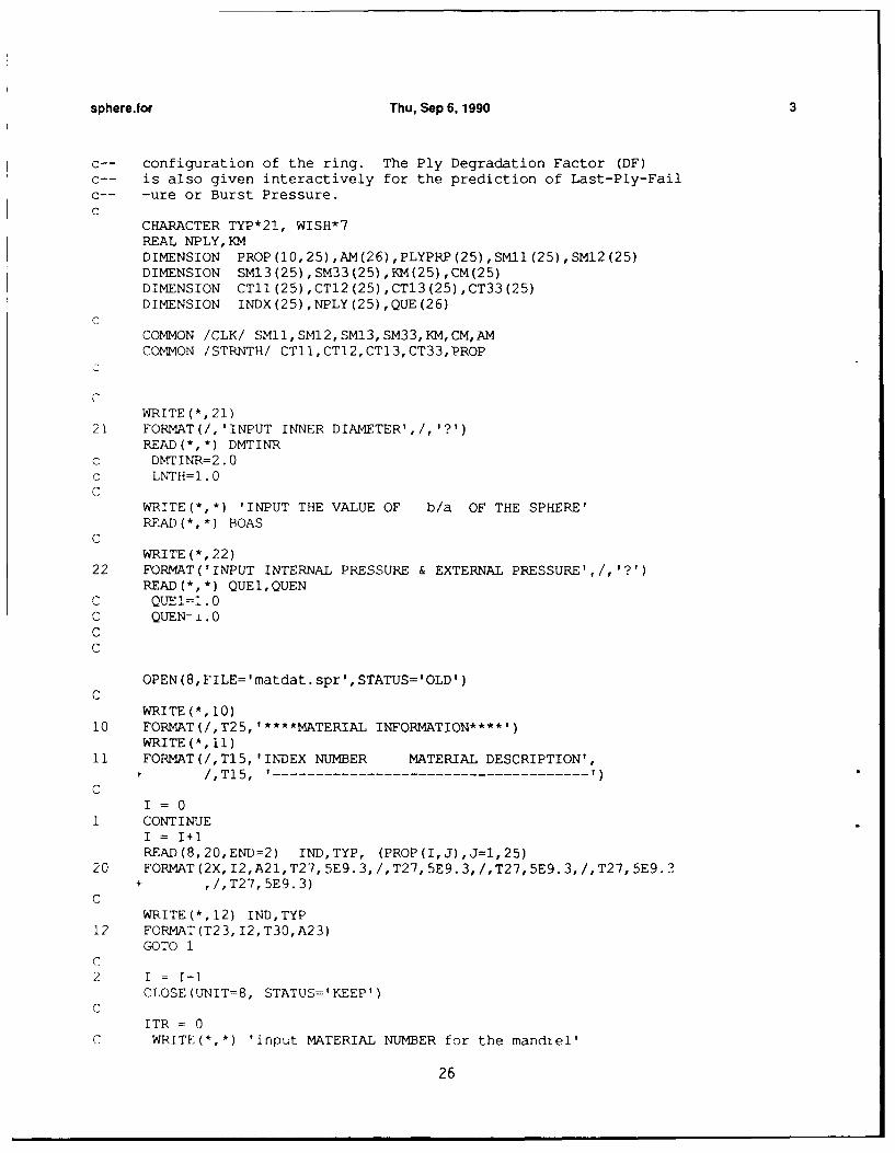
sphere.for Thu, Sep 6, 1990 3
c-- configuration of the ring. The Ply Degradation Factor (DF)C-- is also given interactively for the prediction of Last-Ply-Failc-- -ure or Burst Pressure.c
CHARACTER TYP*21, WISH*7REAL NPLY,KMDIMENSION PROP(I0,25),AM(26),PLYPRP(25),SMII(25),SMI2(25)DIMENSION SMI3(25),SM33(25),KM(25),CM(25)DIMENSION CTII(25),CTI2(25),CTI3(25),CT33(25)DIMENSION INDX(25),NPLY(25),QUE(26)
CCOMMON /CLK/ SM11,SM12,SM13,SM33,KM,CM,AMCOMMON /STRNTH/ CTII,CTI2,CTI3,CT33,PROP
C
WRITE (*, 21)21 FORMAT(/,'INPUT INNER DIAMETER',/,'?')
READ(*,*) DMTINRc DMTINR=2.0C LNTH=. 0C
WRITE(*,*) 'INPUT THE VALUE OF b/a OF THE SPHERE'READ(*,*) BOAS
CWRITE (*, 22)
22 FORMAT('INPUT INTERNAL PRESSURE & EXTERNAL PRESSURE',/,'?')READ (*,*) QUE1,QUEN
C QTTE!=I. 0C QUEN= .0CC
OPEN(8,FILE='matdat.spr',STATUS='OLD')C
WRITE (*, 10)10 FORMAT(/,T25, '****MATERIAL INFORMATION****')
WRITE(*, 11)11 FORMAT(/,T15,'INDEX NUMBER MATERIAL DESCRIPTION',
+ /,T15, ' ------------------- )C
I = 01 CONTINUE
I = I+lREAD(8,20,END=2) IND,TYP, (PROP(I,J),J=l,25)
20 FORMAT(2X,I2,A21,T27,5E9.3,/,T27,5E9.3,/,T27,5E9.3,/,T27,5E9.3+ ,/,T27,5E9.3)
CWRITE(*,12) IND,TYP
12 FORMAT(T23,I2,T30,A23)GOTO 1
C2 I = I-I
CLOSE(UNIT=8, STATUS='KEEP')
ITR = 0C WRITE(*,*) 'input MATERIAL NUMBER for the mandiel'
26

sphere.for Thu, Sep 6, 1990 4
C READl(,* INDX (1)WRITE(-,-) '** INPUT PLY LAYUP INFORMATION (max 25 layers)***,
C51 IR=1R+lWRITE(*, *)
CC WRITE(-,*) 'INPUT THE VALUE OF THE DEGRADATION FACTOR'C WRITE(*,*) I for INTACT plies: DF=l'C READ(*,*) DF
DF=1 .0C BOAS= l.+l./AOTS
c mandrel displacementAM(1) 0.5*DMTINR
C AM(2) =BOAM*AM(l)
C NPLY (1) AM (2) - AM (1)
WRITE(*,*) IINPUT NO OF LAYERS (max 25 layers)'READ(*,*) NM
Do 25 I=l,NM+lQUE(I) = 0.0
25 CONTINUE
QUE41) =QUEl
QUE(NM+l) = QUEN
DO 51 IR=l,NM
WRITE(*,*) **LAYERS ARE NUMBERED FROM INSIDE TO OUTSIDE**WRITE (*,-*)WRITE(*,-) ~*~FOR LAYER ',IR,' **
WRITE(*,*)'INPUT MATL INDEX NO. & THICKNESS FACTOR'C
READ(-,*) INDX(IR),NPLY(IR)NPLY (IR) =NPLY (IR) *(BOAS-l. ) *A~(l)
51 CONTINUE
DO 53 IR=l,NM
DO 50 I - 1,25PLYPRP(I) =PROP (INDX (IR), I)
50 CONTINUECC_- degradation of effective stiffness and compressive strength
PLYPRP(2) =DF* PLYPRP(2)PLYPRP(1) =DF*PLYPRP(3)PLYPRP(5) =DF* PLYPRP(5)
C
AM(IR+l) = AM(IR) + NPLY(IR)CM(IR) = AM(IR)/AM(IR4-l)
CCALL BTCLCT (PLYPRP, IR)
27

sphere for Thu, Sep 6, 1990 5
CKM(IR) = O.5-SQRT(1.+8.*(CT11(IR)+CTl2(IR)-CT13(IR))/CT33(IR))
CC WRITE(*,*) 'DO YOU WANT TO ADD ANOTHER PLY LAYUP? (Y OR N)'
C READl(-, '(A)) WISHCA3 CONTINUE
C IF(WISH .EQ. 'Y') GOTO 51C
RETURNEND
CC
SUBROUTINE BTCLCT (PLYPRP, ITR)
c-- this subroutine is to perform some intermediate calculationsc-- required for the routine 'CAIQUS1 .c
REAL KMC
DIMENSION PLYPRP(25),SMTX(6,6),CTl1(25),CTl2(25),CT13(25 )
DIMENSION CT33(25),AM(26),CTX(6,6),PROP(l0,2 5)DIMENSION XX(6,l),KM(25),CM(25)DIMENSION SMil (25) , M12 (25) , M13 (25) , 5M-3(25)
COMMON /CLK/ SMl1,SM1l2,SM13,SM33,KIA,CM,AMCOMMON /STRNTH/ CTll,CT12,CT13,CT33,PROP
DO 10 I - 1,6XX(I,1) =0.0
DO 11 J = 1,6
CTX(IJ) =0.0
SmrrX(IJ) =0.0
11 CONTINUE10 CONTINUE
C
CTX(1,1) = PLYPRP (1)CTX(1,3) = PLYPRP(3)
CTX(2,1) = CTX(l,2)CTX(2,2) = PLYPRP (4)CTX(2,3) = PTYPRP (5)CTX(3,1) = CTX(1,3)CTX(3,2) = CTX(2,3)CTX(3,3) = PLYPRP(6)CTX(4,4) = PLYPRP (7)CTX(5,5) = PLYPRP(8)CTX(6,6) = PLYPRP (9)
DO 15 1=1,6DO 16 J=1,6SMTX(I,J) = CTX(I,J)
16) CONTINUE
28

sphere.tor Thu, Sep 6, 1990 6
15 CONTINUE
CALL GAUSSJ(SMTX,6,6,XX,1,1)C
CCTll(ITR) = CTX(1,l)CT12(ITR) =CTX(l,2)CT13(ITR) =CTX(l,3)CT33(ITR) = CTX(3,3)
CSMll(ITR) = SMTX(1,l)SMl2(ITR) = SMTX(l,2)SM13(ITR) = SMTX(l,3)SM33(ITR) =SMTX(3,3)
CRETURNEND
CSUBROUTINE CALQUS (NM, QUE)
c-- this subroutine is to calculate the inter-layer normal pressurec-- Q's from a set of simultaneous equations.
REAL KM. MUEREAL AA,BBDIDENSION SMll(25),SM12(25),SM13(25),SM33(25),CM(25)DIMENSION AA(25,25),QUE(26),ALF(25),BTM(25),BB(25,1)DIMENSION SGR(25,1l),SGT(25,l1),STRR(25,l1),FROP(l0,25)DIMENSION STRT(25,ll),EU(25,ll),YY(25,1l),AR(25,11)DIMENSION CTll (25) ,CTl2 (25) ,CTl3 (25) ,CT33 (25)DIMENSION AM(26),KM(25),MUE(25),GMA(25)
COMMON /CLK/ SMll,SMl2,SMl3,SM[33,KM,CM,AMCOMMON /STRNTH/ CTll,CTl2,CTl3,CT33,PROPCOMMON /SIZE/ AA,BBCOMMON /SSDP/ SGR, SGT, STPR, STRT, EU, YY, AR
DO 10 I = 1, NM-l
BB(I,l) = 0.0
DO 11 J = ,NM-1AA(I,J) = 0.0
11 CONTINUE1C CONTINUE
DO 20 I=l,NM
MUE(I) = (l.-CM(I)**(2.*KM(I) ))*((KM(I)+.5)*CT33(I)I -2.*CT13(I))*((KM(I)-.5)*CT33(I)+.2.*CT13(I))ALF(T) = 2.*KM(I) *CT33(I)*CM(I)** (KM(I)+.5) /MUE(I)
BTM(I) = (l.-CM(I)-*(2.*KM(I)) )*(.5*CT33(I)-..2CTl3(I))
29

sphere.for Thu, Sep 6, 1990 7
/MUE (I)GMA(I) = KM(I)*(1.+CM(I)**(2.*KM(I)))*CT33(I)/MUJE(I)
20 CONTINUE
IF (NM .EQ. 1) GOTO 50
IF((NM-1) .EQ. 1) THEN
AA(1,1) = (BTM(2).-BTM(l)-GMA(2)-GMA(1))*AM(2)
QUE (2) =BB (1) /AA (1, 1)ELSE
D0 40 I=1,NM-1
IF(I .EQ. 1) THEN
BB (1,1) = -AM (I)*-ALF (I) *QUE (1)AA(I,I) = AM(2)*(BTM(I+1)-BTM(I)-GM4A(I+1)-GMA(I))
ELSEIF (I .EQ. (NM~ _-, THEN
AA(I,NM-1) = 1M(I+1)*(BTM(I+1)-BTM(I)-GMA(I+1)-GMA(I))AA(I,NM-2) AM(I)*ALF (I)
ELSE
BB(I,1) =0.0AA(I,I-1) = AM(I)*ALF (I)AA(I,I) = AM(I4+1)*(BTM(I+1)-.BTM(I)-GMA(I+i)-GMA(I))
AA(I,I+l) = AM(I+2)*ALF(I+1)/CM(I~1)
ENDIF
40 CONTINUE
NMM1 = NM-iIFAIL = 0
CALL GAUS-SJ(AA,NI4M1,25,BB,1,1)
DO 30 Il, NM-iQUE(I+1) = BB (1,1)
30 CONTINUE
END IF
50 CONTINUE
RETURNEND
CSUBROUTINE STSDSP (NM, QUE, ND)
30

sphere.f or Thu, Sep 6, 1990 8
c-- to calculate stress, strain and displacement field based onc-- the thick sphere formulation.
REAL KM
DIMENSION YY(25,ll),SGR(25,ll),SGT(25,ll),EU(25,ll),SMl(25)DIMENSION SMl2(25),SMl3(25),SM33(25),CM(25),AM(26),KM(25)DIMENSION CTll(25),CTl2(25),CTl3(25),CT33(25),PROP(l0,25)DIMENSION AR(25,ll),STRR(25,ll),STRT(25,ll)DIMENSION QUE(26)
COMMON /CLK/ SMll, SM12, SM13,SM33,KM[,CM,AMCOMMON /STPNTH/ CTll,CTl2,CTl3,CT33,PROPCOMMON /SSDP/ SCR, SGT, STRR, STRT, EU, YY, AR
WRITE(-,-*)WRITE(*,*) 'INPUT NO OF EQUIDISTANT CALCULATION POINTS THRU+THICKNESS IN EACH LAYER'
WRITE(*,*) I'(max 11, min 2)'READ(*,*) ND
DO 40 I =l,NM
FCT =(AM(I+l)-AM(I))/(ND-l)
1 .1 (1.-CM(I)** (2.*KM(I)))CNST2 =(KM(I)-.5)*CT33(I) + 2.*CTl3(I)CNST3 =(KM(I)+.5)*CT33(I) - 2.*CT13(I)CNST4 =CT11(I)+CTl2(I)+(KM(I)-.5)*CT13(I)
CNST5 =CT11(I)+CT12(I)-(KM(I)+.5)*CT13(I)
DO 45 J = 1,ND
YY(I,J) = AM (I) + (J-1) *FCT
c-- I for layers, increasing from inside to outsidec_- J for calculation points, incresing from inside to outside
c-- radial stressSGR(I,J) = CNSTl*((QUE(I)*CM(I)**(KM(I)+1.5)-QUE(I+1))*
*1 (YY(I,J)/AM[(I+l))**(KM(I)-l.5) -2 (QUE(I)-QUE(I+1)*CM(I)**(KM(T-)-l.5))*3 CM(I)**(KM(I)+l.5)*(AM(I+1)/YY(I,J))**(KM(I)+1.5))
* c-- hoop stressSGT(I,J) = CNST1*(CNST4/CNST2)*(QUE(I)*CM(I)**(KM(I)+1.5)1 -QUE(I+l))*(YY(I,J)/AM(I+l))**(KM(I)-l.5) +2 CNSTl* (CNST5/CNST3)* (QUE(I)-QUE(I+l)*3 CM (I) * *(KM (1)-1. 5)) *4 CM(I)** (KM(I)+l.5)* (AM(I+l)/YY(I,J) )**(KJM(I)+1.5)
45 CONTINUE40 CONTINUE
DO 50 I=l,NMDo 60 J=l,ND
31

sphere.for Thu, Sep 6, 1990 9
c-- radial strainSTRR(I,J) = SM33(I)*SGR(I,J)+2.*SMl3(I)-SGT(I,J)
c-- hoop strainSTRT(I,J) = SMl3(I)-SGR(I,J)+(SMll(I)+SMl2(I))*SGT(I,J)
c-- radial displacementEU(I,J) =STRT(I,J)*YY(I,J)
60 CONTINUE50 CONTINUE
RETURNEND
CSUBROUTINE STRIO (NM, ND, ITK, 3TK,ARMN, DF, INDX)
c-- to obtain the strength ratio for predicting the failurec-- pressure.
DIMENSION SMll(25),SM12(25),SMl3(25),SM33(25),KM(25)DIMENSION CM(25),AM(25),INDX(25),PROP(10,25),CMTX(6,6)DIMENSION CTll (25) ,CT12 (25) ,CTl3 (25) ,CT33 (25)DIMENSION SGR(25,ll),SGT(25,ll),STRR(25,ll),STRT(25,ll)DIMENSION EU(25,ll),YY(25,ll),AR(25,ll),PLYPRP(25)DIMENSION GE(6,6),GEE(6),AF(6,6),AFF(6)
COMMON /CLK/ SMl1l,SM12, SM13,SM[33,KM[,CM[,AMCOMMON /STRNTH/ CTll,GTl2,CTl3,CT33,PROPCOMMON /SSDP/ SGR, SGT, STRR, STRT, EU, YY, AR
DO 2 I=1,6AFF(I) =0.0
Do 3 J=1,6AF(I,J) =0.0
3 CONTINUE2 CONTINUE
DO 10 I=l,NM
DO 50 IR = 1,25PLYPRP (IR) = PROP (INDX (I) ,IR)
50 CONTINUE
C-- degradation of unidirectional stiffness properties
PLYPRP(1l) = DF**0.2*PLYPRP(11)PLYPRP(22) = DF* PLYPRP(22)PLYPRP(23) = DF*PLYPRP (23)PLYPRP(25) = DF* PLYPRP(25)
c-- 3: fiber direction
32

sphere.for Thu, Sep 6, 1990 10
c-- 1 & 2: transverse to the fiberAF(l,l) = 1./(PLYPRP(12)*PLYPRP(13))AF(2,2) = AF(l,l)AF(3,3) = l./(PLYPRP (l0)*PLYPP(11))AF(4,4) = 1l. /(PLYPRP (14)**2)AF(5,5) = AF(4,4)AF(6,6) = 0.60/PLYPRP(l0)AFF(l) = l./PLYPRP(12) - l./PLYPRP(13)AFF(2) = AFF(l)AFF(3) = 1./PLYPRP(l0) - l./PLYPRP(ll)AF(l,2) = PLYPRP(16)*SQRT(AF(1,l)*AF(2,2))AF(1,3) = PLYPRP(15)*SQRT(AF(l,l)*AF(3,3))AF (2, 3) =AF(l,3)AF(2,l) = AF(l,2)AF(3,l) = AF(1,3)AF(3,2) = AF(2,3)
CALL CTX3D (PLYPRP, Cr-TX)
CALL G3DCLT(CMTX,AF,AFF,GE,GEE)
DO 11 J=1,ND
AA = ABS((GE(3,3)+2.*GE(3,2)+GE(2,2))*STRT(I,J)**21 +2.*(GE(3,l)+GE(2,l))*STRT(T,J)*STRR(I,J)2 +GE (1,1)*-STRR(I, J)**2)
BB = (GEE(3)+GEE(2))*STRT(I,J)+GEE(1)*STRR(I,J)
C--- strength ratios based on thick preeuse vessel solutionAPII,J) = -(BB/(2.*AA)) +SQRT((BB/(2.*AA))**2 +l./AA)
11 CONTINUE10 CONTINUE
c-- AJPMN: minimum value of streng-th ratios based on thick pressurec-- vessel solution.
CALL VARMN (AR, ARMN, NM, ND, ITK, JTK)
RETURNEND
SUBROUTINE VARMN (AR, ARMN, NM, ND, ITK, JTK)
DIMENSION AR(25,ll)
ITK = 1JTK = 1APRMN = AR (1,1)
33

sphere.for Thu, Sep 6, 1990 11
DO 12 I=1,NMDO 11 J = 1,ND
IF(AR(I,J) .GE. ARMN) GOTO 11ITK = IJTK = JARMN = AR(I,J)
11 CONTINUE12 CONTINUE
RETURNEND
CSUBROUTINE G3DCLT (CTX,AF,AFF,GE, GEE)
DIMENSION CTX(6,6),GE(6,6),TMP1(6,6),GEE(6),TMP2(6)DIMENSION AF(6,6), AFF(6)
DO 5 I=1,6DO 7 J=l,6TMP2(I) = 0.0TMPI(I,J) = 0.0GE(I,J) = 0.0
7 CONTINUE5 CONTINUE
DO 10 I=1,6DO 11 J=1,6DO 12 K=1,6TMP1(I,J) = TMP1(I,J) + AF(I,K)*CTX(K,J)
12 CONTINUE11 CONTINUE10 CONTINUE
DO 20 I=1,6DO 21 J=1,6DO 22 K=1,6GE(I,J) = GE(I,J) + CTX(I,K)*TMP1(K,J)
22 CONTINUE21 CONTINUE20 CONTINUE
DO 30 I=1,6DO 31 J=l,6TMP2(I) = TMP2(I) + AFF(J)*CTX(J,I)
31 CONTINUE30 CONTINUE
DO 40 I=1,6GEE(I) = TMP2 (I)
40 CONTINUE
RETURNEND
C--c-- the routine for solving a system of simulteneous equations
34

sphere.for Thu, Sep 6, 1990 12
SUBROUTINE GAUSSJ(A,N, NP, B,M,MP)PARAMETER (NMAX=50)DIMENSION A(NP,NP) ,B(NP,MP) ,IPIV(NMAX) ,INDXR(NMAX) ,INDXC(NMAX)DO 11 J=1,N
IPIV (J) =011 CONTINUE
DO 22 I=1,NBIG=O0.DO 13 J=1,N
IF(IPIV(J) .NE.1)THENDO 12 K=1,N
IF (IPIV(K).EQ.0) THENIF (ABS(A(J,K)) .GE.BIG) THEN
BIG--ABS (A (J, K))IROW=JICOL=K
END IFELSE IF (IPIV(K).GT.1) THENPAUSE 'Singular matrix'
END IF12 CONTINUE
ENDI F13 CONTINUE
IPIV(ICOL)=IPIV(ICOL) +1IF (IROW.NE.ICOL) THENDO 14 L=-1,N
DUM=A (I ROW, L)A (I ROW, L) =Ax (I COL, L)A (I COL, L) =DUM
14 CONTINUEDO 15 L=1,M
DUM=B (IROW, L)B (I ROW, L) =B (I COL, L)B (ICOL, L)=DUN
15 CONTINUEEND IFINDXR (I) =IROWINDXC (I) =ICOLIF (A(ICOL,ICOL).EQ.0.) PAUSE 'Singular matrix.'PIVINV=1.IA (ICOL, ICOL)A (ICOL, ICOL,) 1.DO 16 L=1,N
A(ICOL,L)=A(ICOL,L) *PIVINV16 CONTINUE
DO 17 L=1,MB (ICOL, L) =B(ICOL, L) *PIVINV
17 CONTINUEDO 21 LL=1,N
IF (LL.NE. ICOL) THENDUM=A (LL, ICOL)A (LL, ICO,) '-.DO 18 L=1,N
A (LL,T) =A (1T-,L)-A (I COL, L)*DUM18 CONTINUE
DO 19 L-L,MB(LL,LII=B (LL,L)-B (ICOL,L) *DUM
19 CONTINUE
35

sphere.for Thu, Sep 6, 1990 13
END IF21 CONTINUE22 CONTINUE
DO 24 L=N,1,-1IF(INDXR(L) .NE.INDXC(L) )THEN
DO 23 K=l,NDUM=A(K,INDXR(L))A(K,INDXR(L) )=A(K,INDXC(L))A (K, INDXC (L) ) =DUM
23 CONTINUEENDIF
24 CONTINUERETURNEND
C--SUBROUTINE CTX3D (PLYPRP, CTX)
c-- formulation of three-dimensional PLY stiffness matrix
REAL NU21DIMENSION PLYPRP (25) ,CTX (6, 6)
NU21 = PLYPRP (23) *PLYPRE (22) /PLYPRP (21)VE = l./((l.+PLYPRP(24))*(l.-PLYPRP(24)-~2.*PLYPRP(23)*NU21))
C
CTX(l,l) = (1.-NU2l*PLYPRP(23))-VE,*PLYPRP(22)CTX(1,2) = (PLYPRP(24)+NU21*PLYPRP(23))*VE*PLYPRP(22)CTX(1,3) = NU21*(l.+PLYPRP(24))*VE*PLYPRP(21)CTX(2,1) =CTX(1,2)CTX(2,2) = CTX(,l)CTX(2,3) = CTX(1,3)CTX(3,1) = CTX(1,3)CTX(3,2) = CTX (2, 3)CTX(3,3) = (l.-PLYPRP(24)**2)*VE*PLYPRP(21)CTX(4,4) = PLYPRP (25)CTX(5,5) = CTX(4,4)CTX(6,6) = (l.-PLYPRP(24)-2.*NTJ21*PLYPRP(23))*VE*PLYPRP(22)/2.
RETURNEND
36

Listing of the material data file "matdat.spr" for SPHERE
1T3/5203(pi/4] .772E11 .235Ell .27E10 .772E11 .27E10.13E11 .57E10 .57E10 .268E11 .15E10.15E10 .40E8 .246E9 .68E8 -0.5E0-.80E0 .02E-6 22.5E-6 .6E-6 0.20.181E12 .103EI1 .28E0 0.52E0 .717E10
2 f-IM6/EP~pi/4J .871E11 .267Ell .44E10 .871E11 .44E10.154E11 .50E10 .50E10 .302E11 .35E10.154E10 .56E8 .15E9 .98E8 -0.50E3-.80E0 .0 0.0 0.0 0.1.203E12 .112E11 0.32E0 0.60E0 .84E10
3 E-Glassrpi/4] .223E11 .737E10 .477E10 .223Ell .477E10.123E11 .319E10 .319E10 .747EI0 .106E10.61E9 .31E8 .118E9 .72E8 -0.5E0-.80E0 8.6E-6 22.lE-6 0.6E-6 0.07.386E11 .82?E10 0.26E0 0.6OEO .414E10
4 AL 2014 .101E12 .462Ell .462E11 .101E12 .462Ell.101E12 .276E11 .276E11 .276Ell .449E9.897E9 .449E9 .897E9 .283E9 -0.5E0-0.5E0 23.2E-6 23.2E-6 0.0 0.0.725Ell .725E11 0.313E0 0.313E0 .276Ell
5 SS A!-!50 .284E12 .133E12 .133E12 .284E12 .133E12.284E12 .75E11 .75Ell .75El1 .114E10.228E10 .114E10 .228E10 .738E9 -0.5E0-0.5E0 11.7E-6 11.7E-6 0.0 0.0.200E12 .200OE12 0.318E0 0.318E0 .750E11
Number Name Cl). C12 C13 C22 C23C33 C44 C55 C66 X
X1Y Y1 S Fxy*Fyz* alfi alf2 bta2 *Ex Ey nu2l nu32 Es
CijIs are the elements of the effective stiffness matrix in PaEi's are the elements of the Young's Moduli of an unidirectional ply in Pa
37

This is the print out of the input-output sequence for the code "sphere".This run is for a hybrid sphere of b/a=1.25, and 50% of thickness ofT300/5208 inside and rest of IM6/Epoxy outside. The sphere is subjectedto internal pressure.
INPUT OUTPUT FILE NAME
T3IM6
INPUT INNER DIAMETER
>1.0
INPUT THE VALUE OF b/a OF THE SPHERE>1.25
INPUT INTERNAL PRESSURE & EXTERNAL PRESSURE
>1 0
****MATERIAL INFORMATION****
INDEX NUMBER MATERIAL DESCRIPTION
1 T3/5203[pi/4]2 H-IM6/E?[pi/4]3 E-Glass[pi/4]4 AL 20145 SS AM350
* INPUT PLY LAYUP INFORMATION (max 25 layers)***
INPUT NO OF LAYERS (max 25 layers)
>2
** LAYERS ARE NUMBERED FROM INSIDE TO OUTSIDE **
FOR LAYER 1 ***INPUT MATL INDEX NO. & THICKNESS FACTOR>1 .5
** LAYERS ARE NUMBERED FROM INSIDE TO OUTSIDE **
FOR LAYER 2 ***INPUT MATL INDEX NO. & THICKNESS FACTOR>2 .5
INPUT NO OF EQUIDISTANT CALCULATION POINTS THRU THICKNESS IN EACH LAYER(max 11, min 2)>3
*** PLEASE WAIT ***
38

LISTING OF THE OUTPUT FILE "T31M6"
inner radius(meter), outer radius (meter).500000 .625000
b/a SPHERE1. 25000
mat # r,meter sig(r),a, sig(th)=sig(phi),Ma1 0.500000E+00 -.100000E-05 0.244346E-051 0.531250E+00 -. 637914E-06 0.194125E-051. 0.562500E+00 -.377960E-06 0.162349E-052 0.562500E+00 -.377959E-06 0.179410E-052 0.593750E+00 -.166265E-06 0.159966E-052 0.625000E+00 0.OOOOOOE+00 0.149123E-05
mat # r,meter eps(r) eps(th)-eps(phi) u(r),mm1 0.500000E+00 -.879822E-10 0.266238E-10 0.133119E-071 0.531250E+00 -.577207E-10 0.208252E-10 0.110634E-071 0-562500E+00 -.361736E-10 0.170920E-10 0.961423E-082 0.562500E+00 -.343097E-10 0.170920E-10 0.961423E-082 0.593750E+00 -.192543E-10 0.148012E-10 0.878822E- 082 0.625000E+00 -.765717E-11 0.134000E-10 0.837503E-08
mat # r(meter) strength ratio1 0.500000E+00 0.240422E+091 0.531250E+00 0.307092E+092. 0.562500E+00 0.348892E+092 0.562500E+00 0.327183E+092 0.593750E+00 0.368268E+092 0.625000E+00 0.272434E+09
FAILURE LOCATION & FAILURE 2RESSUREmat # r(meter), INT PRESSURE, EXT PRESSURE (in Pa)
1 0.500000E+00 0.240422E+09 0.OOOOOOE+00END OF OUTPUT
39*U.S. GOVERNMAENT PRINTING omcE: I"99. $48-076/I40