speed control of bldc motor drive under dtc and indirect flux control...
TRANSCRIPT
Speed Control of BLDC Motor Drive under DTC and Indirect Flux Control Scheme using SVPWM TechniqueTeja Sreenu Tadivaka* and S.V.N.L. Lalitha*
Abstract: Brushless dc (BLDC) motor became indispensable in most of the industrial drive applications due to its high efficiency, higher power density, easy maintenance and control, and high torque to inertia ratio. In this paper a sensorless Space Vector Pulse Width Modulation based direct torque and indirect flux control of BLDC has been investigated. Several methods are proposed in the literature to obtain higher torque with better control on current and torque with minimal fluctuations in current /torque. Most of the proposed techniques are complex and they do not take stator flux control in to account, so that high speed operations are not possible with this drive. The proposed sensorless method employs Direct Torque control method for controlling stator flux indirectly and toque directly by varying direct axis current. Space vector pulse width modulation technique used in this paper gives better performance than the conventional PWM and vector control techniques in terms of controlling the variations in direct axis current. The proposed sensorless Direct Torque and indirect flux Control of BLDC motor drive has been simulated in the MATLAB/SIMULINK environment and results are obtained.
Keywords: BLDC Motor, Stator flux control, Direct Torque Control (DTC), Space Vector Pulse Width Modulation (SVPWM).
INTRODUCTION1. Brushless DC motor is the better option in the present day industrial applications requiring high accuracy, higher efficiency and high power density. Usually BLDC motor is accounted as high pursuance motor which is efficient in generating more amounts of torque over wide speed ranges. BLDC motors give the same performance as a DC motor by exhibiting the some torque-speed characteristics. Additional advantage of BLDC motor over DC motor is related to the usage of brushes. Like DC motor BLDC motor does not require brushes as they are electronically commutated. Commutation is nothing but changing current from one phase to another phase of winding at desired time to create unidirectional torque. The commutation sequences are desired by the rotor position with respective stator windings and the rotor position is detected either by using position sensors or by sensor less techniques
For BLDC motors with trapezoidal shape back emf obtaining low frequency ripple free torque, and instantaneous torque and flux are major considerations. So in order to obtain the control on flux and torque there are different methods that are stated for sensorless control of BLDC they are:
1. Measurement of back EMF
2. Method of Back EMF integration
3. Method of Flux estimation
4. Freewheeling current detection method
The above stated methods have there own advantages and disadvantages and moreover the newer techniques that are evolved made them a bit effective less as some of the techniques needs hardware equipment for sensing purpose.* Department of EEE, K.L. University. Email: [email protected] and [email protected]
I J C T A, 10(5) 2017, pp. 929-937© International Science Press
930 Teja Sreenu Tadivaka and S.V.N.L. Lalitha
This paper presents a simple sensorless indirect flux control and direct torque of BLDC motor, similar to the normal Direct torque control used for sinusoidal alternating current motors where torque generated and flux are regulated at the same time. This method give advantages of fast torque response compared to vector control as lick conventional DTC, and position-sensorless drive. The BLDC motor rotor position is known by calculating stationary reference frame stator flux linkages and winding inductance and stator currents.
The basic property of Direct Torque Control is that to select the voltage vector in relation with the error between reference and calculated torque and flux linkage values. In the proposed scheme, the main control moto is to keep the motor’s amplitude of the stator flux and developing torque within particular edges. The inverter is triggered by SVM controllers to switch whenever these limits are exceeded.
MODeLLINg Of BRUShLeSS DC MOTOR2. BLDC motors is one of the motor which rotates in synchronism. As its name says synchronism, the magnetic field created by both the stator and rotor rotates with the same speed in air gape of rotor stator. So BLDC motors do not experience any “slip” which is normally observed in induction motors. BLDC motor is built with wire wound stator poles and a permanent magnet rotor.
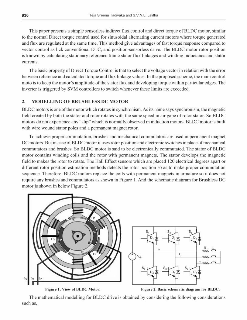
To achieve proper commutation, brushes and mechanical commutators are used in permanent magnet DC motors. But in case of BLDC motor it uses rotor position and electronic switches in place of mechanical commutators and brushes. So BLDC motor is said to be electronically commutated. The stator of BLDC motor contains winding coils and the rotor with permanent magnets. The stator develops the magnetic field to makes the rotor to rotate. The Hall Effect sensors which are placed 120 electrical degrees apart or different rotor position estimation methods detects the rotor position so as to make proper commutation sequence. Therefore, BLDC motors replace the coils with permanent magnets in armature so it does not require any brushes and commutators as shown in Figure 1. And the schematic diagram for Brushless DC motor is shown in below Figure 2.
figure 1: View of BLDC Motor. figure 2. Basic schematic diagram for BLDC.
The mathematical modelling for BLDC drive is obtained by considering the following considerations such as,
931Speed Control of BLDC Motor Drive under DTC and Indirect Flux Control Scheme using SVPWM...
1. It has three symmetrical windings.
2. Has no magnetic saturation.
3. Neglecting hysteresis and eddy current losses.
4. Ignorance of mutual inductance.
5. And neglecting armature reaction.
The mathematical modelling is obtained by considering the KVL equations for Figure 2.
Va = i r didt
ea aa
a+ +L
Vb = i r didt
eb bb
b+ +L
Vb = i r didt
ec cc
c+ +L (1)
For solving these equations, in this paper we used a concept of line-to-line park’s transformation technique. This line-to-line parks transformation converts the three phase voltages to two phase coordinators expressed as,
VV
ab
ca
È
ÎÍ
˘
˚˙ =
- -
-
È
Î
ÍÍÍÍ
˘
˚
˙˙˙˙
È
Î
ÍÍÍ
˘
˚
˙˙˙
13
13
33
33
VVV
a
b
c
(2)
The matrix coordinates obtained from the above line to line park’s transformation are transformed to orthogonal matrix coordinates (a, b). Similarly, same like as voltage, the three phase currents also transformed to two phase orthogonal matrix. These two phase currents (Ia, Ib) and voltage (Va, Vb) are used for calculating the flux linkages (ya, yb) from the expression described as,
ya = 1L
Va
a a( )- i ra
yb = 1L
Vb
b b( )- i ra (3)
And from this equation the phase angle is calculated as,
y = ya + jyb
q = tan-1(yb/ya) (4)
The measured values of direct axis and quadrature axis currents are obtained by the following matrix,
iid
q
È
ÎÍ
˘
˚˙ = 2
330 30
30 30- - +
+ - -È
ÎÍ
˘
˚˙
È
ÎÍ
˘
˚˙
sin ( ) sin ( )cos ( ) cos ( )
q qq q
a
b
ii (5)
These obtained measured are compared with reference direct and quadrature axis currents for obtaining error tolerance. The reference current signals are obtained by the electromagnetic torque. From the definition of newton’s law of motion, the total applied torque is equal to sum of all individual torques across each element.
932 Teja Sreenu Tadivaka and S.V.N.L. Lalitha
Te = T J Bmm
mdwdt
w+ + (6)
The electromagnetic torque generated by a BLDC motor is expressed as
Te = e i e i e i
wa a b b c c
m
+ + (7)
Assuming the three phase windings are symmetrical, so that the amplitudes of currents and back emfs should be equal for three phases. From the above two equations, the electromagnetic torque can be developed by a BLDC motor at any instant is
Te = 2e iw
p p
m (8)
Where ep is called phase back emf and ip is a non-zero phase current.
The back EMF for a BLDC motor is given as
ep = kwm (9)
The error difference is obtained from comparison of the currents is given to SVM controller for obtaining the gate pulses to the three phase inverter.
SpaCe VeCTOR MODULaTION TeChNIqUe3. It is a different approach for getting gate triggering signals instead of general pulse width modulation technique which is based on the space vectors generated by the system two phase vector components d, q axis.
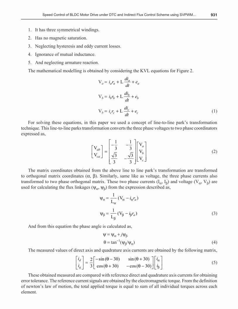
Figure 3 shows the space vector representation of the adjacent vectors S1 and S2 with 8 space vector switching pattern positions of inverter.
figure 3: Space Vector Modulation Technique
Generally, the Space Vector Modulation Technique is one of the most popular methods in PWM techniques fed for the three phase voltage source inverters. By using Space Vector Modulation the harmonic content in both output voltage and output currents are reduced. The space vector modulation technique is used in this paper for creating the reference vectors generated by modulating the switching time sequence of space vectors in each of six sectors as shown in Figure 3. From Figure 3, six switching sectors are used for inversion purpose and two sectors are behave like a null vectors.
Space vector PWM can be implemented by the following steps:1. Transform 3-phase to 2-phase quantity and determine Vs and angle.2. Determine time duration T1, T2 and T0.
933Speed Control of BLDC Motor Drive under DTC and Indirect Flux Control Scheme using SVPWM...
Equation (10) gives the reference space vector V*, where T1, T2 are the time intervals of application of vector S1 and S2 respectively, and zero vectors S0 and S7 are selected for T0.
V ¥ Tz = S T S T ST2
ST2
0 01 1 2 2 0 7¥ + ¥ + ¥ + ¥ (10)
The electric rotor position qre which is required in torque estimation can be found using the Equation.
qre = tan- --
ÊËÁ
ˆ¯̃
1 yy
b
a
b
a
s
s
s s
s s
ii
LL
(11)
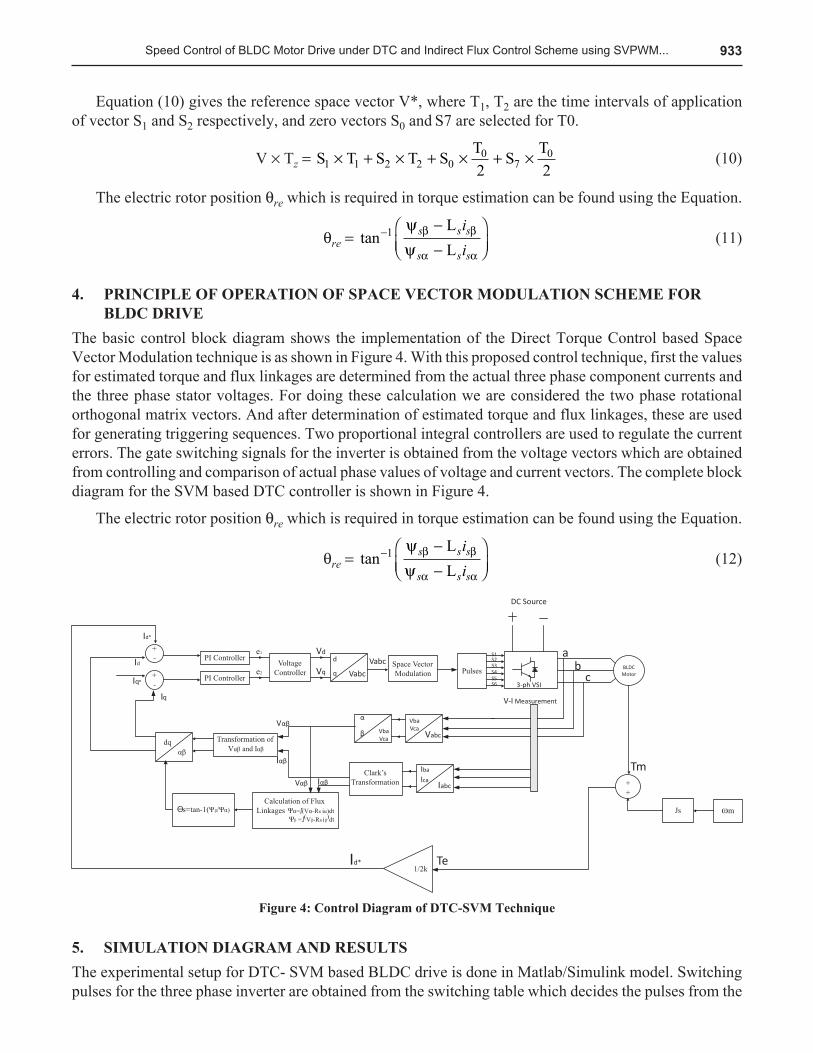
pRINCIpLe Of OpeRaTION Of SpaCe VeCTOR MODULaTION SCheMe fOR 4. BLDC DRIVe
The basic control block diagram shows the implementation of the Direct Torque Control based Space Vector Modulation technique is as shown in Figure 4. With this proposed control technique, first the values for estimated torque and flux linkages are determined from the actual three phase component currents and the three phase stator voltages. For doing these calculation we are considered the two phase rotational orthogonal matrix vectors. And after determination of estimated torque and flux linkages, these are used for generating triggering sequences. Two proportional integral controllers are used to regulate the current errors. The gate switching signals for the inverter is obtained from the voltage vectors which are obtained from controlling and comparison of actual phase values of voltage and current vectors. The complete block diagram for the SVM based DTC controller is shown in Figure 4.
The electric rotor position qre which is required in torque estimation can be found using the Equation.
qre = tan- --
ÊËÁ
ˆ¯̃
1 yy
b
a
b
a
s
s
s s
s s
ii
LL
(12)
figure 4: Control Diagram of DTC-SVM Technique
SIMULaTION DIagRaM aND ReSULTS5. The experimental setup for DTC- SVM based BLDC drive is done in Matlab/Simulink model. Switching pulses for the three phase inverter are obtained from the switching table which decides the pulses from the
934 Teja Sreenu Tadivaka and S.V.N.L. Lalitha
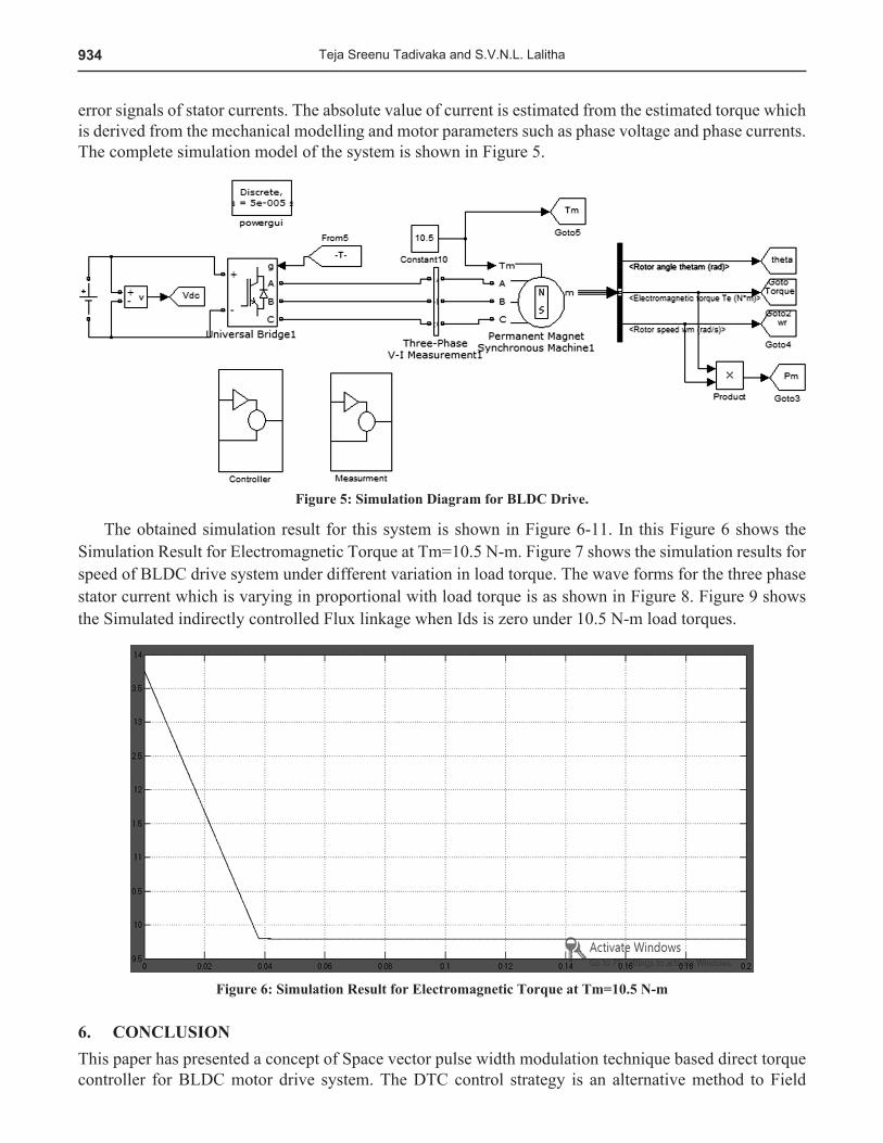
error signals of stator currents. The absolute value of current is estimated from the estimated torque which is derived from the mechanical modelling and motor parameters such as phase voltage and phase currents. The complete simulation model of the system is shown in Figure 5.
figure 5: Simulation Diagram for BLDC Drive.
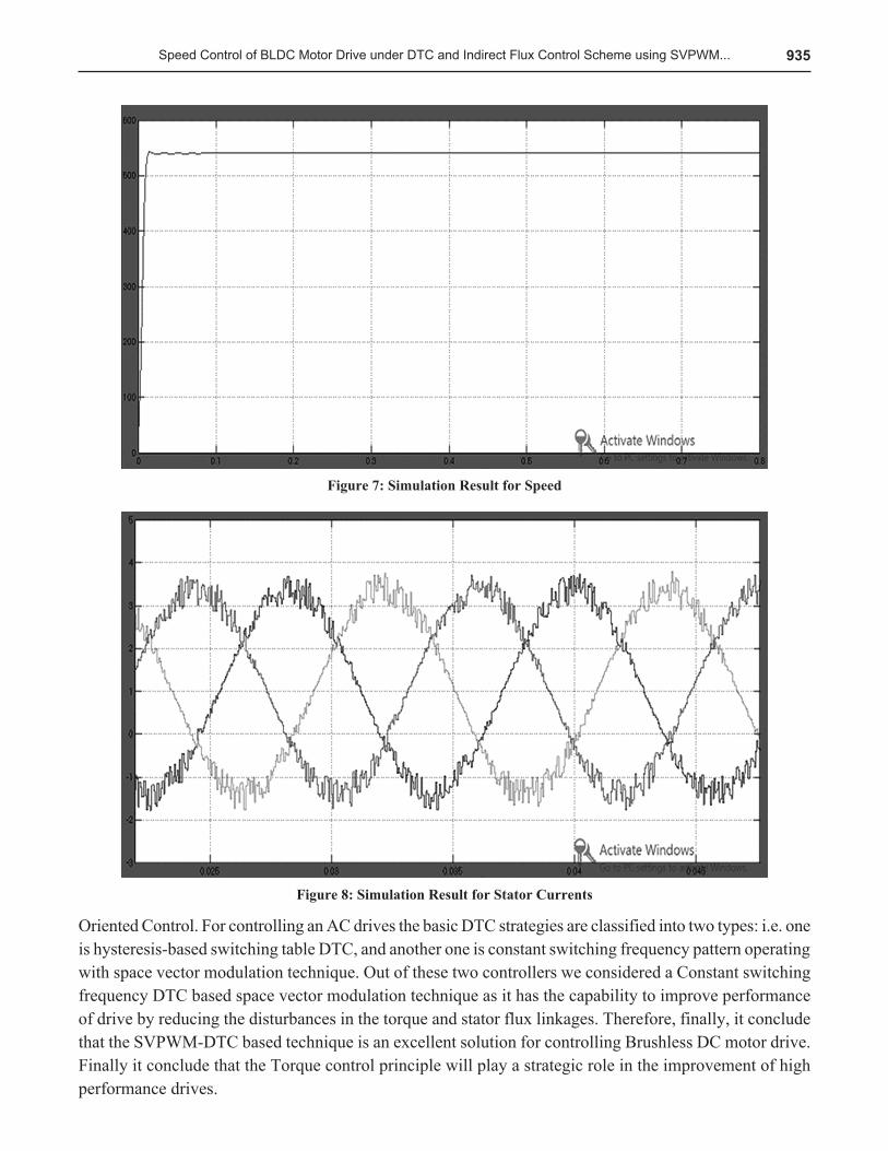
The obtained simulation result for this system is shown in Figure 6-11. In this Figure 6 shows the Simulation Result for Electromagnetic Torque at Tm=10.5 N-m. Figure 7 shows the simulation results for speed of BLDC drive system under different variation in load torque. The wave forms for the three phase stator current which is varying in proportional with load torque is as shown in Figure 8. Figure 9 shows the Simulated indirectly controlled Flux linkage when Ids is zero under 10.5 N-m load torques.
figure 6: Simulation Result for electromagnetic Torque at Tm=10.5 N-m
CONCLUSION6. This paper has presented a concept of Space vector pulse width modulation technique based direct torque controller for BLDC motor drive system. The DTC control strategy is an alternative method to Field
935Speed Control of BLDC Motor Drive under DTC and Indirect Flux Control Scheme using SVPWM...
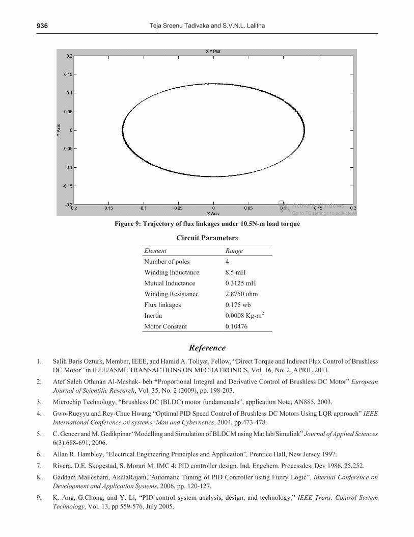
figure 7: Simulation Result for Speed
figure 8: Simulation Result for Stator Currents
Oriented Control. For controlling an AC drives the basic DTC strategies are classified into two types: i.e. one is hysteresis-based switching table DTC, and another one is constant switching frequency pattern operating with space vector modulation technique. Out of these two controllers we considered a Constant switching frequency DTC based space vector modulation technique as it has the capability to improve performance of drive by reducing the disturbances in the torque and stator flux linkages. Therefore, finally, it conclude that the SVPWM-DTC based technique is an excellent solution for controlling Brushless DC motor drive. Finally it conclude that the Torque control principle will play a strategic role in the improvement of high performance drives.
936 Teja Sreenu Tadivaka and S.V.N.L. Lalitha
figure 9: Trajectory of flux linkages under 10.5N-m load torque
Circuit parameters
Element RangeNumber of poles 4Winding Inductance 8.5 mHMutual Inductance 0.3125 mHWinding Resistance 2.8750 ohmFlux linkages 0.175 wbInertia 0.0008 Kg-m2
Motor Constant 0.10476
ReferenceSalih Baris Ozturk, Member, IEEE, and Hamid A. Toliyat, Fellow, “Direct Torque and Indirect Flux Control of Brushless 1. DC Motor” in IEEE/ASME TRANSACTIONS ON MECHATRONICS, Vol. 16, No. 2, APRIL 2011.
Atef Saleh Othman Al-Mashak- beh 2. “Proportional Integral and Derivative Control of Brushless DC Motor” European Journal of Scientific Research, Vol. 35, No. 2 (2009), pp. 198-203.
Microchip Technology, “Brushless DC (BLDC) motor fundamentals”, application Note, AN885, 2003.3.
Gwo-Rueyyu and Rey-Chue Hwang “Optimal PID Speed Control of Brushless DC Motors Using LQR approach” 4. IEEE International Conference on systems, Man and Cybernetics, 2004, pp.473-478.
C. Gencer and M. Gedikpinar “Modelling and Simulation of BLDCM using Mat lab/Simulink” 5. Journal of Applied Sciences 6(3):688-691, 2006.
Allan R. Hambley, “Electrical Engineering Principles and Application”6. , Prentice Hall, New Jersey 1997.
Rivera, D.E. Skogestad, S. Morari M. IMC 4: PID controller design. Ind. Engchem. Processdes. Dev 1986, 25,252.7.
Gaddam Mallesham, AkulaRajani,”Automatic Tuning of PID Controller using Fuzzy Logic”, 8. Internal Conference on Development and Application Systems, 2006, pp. 120-127,
K. Ang, G.Chong, and Y. Li, “PID control system analysis, design, and technology,” 9. IEEE Trans. Control System Technology, Vol. 13, pp 559-576, July 2005.

937Speed Control of BLDC Motor Drive under DTC and Indirect Flux Control Scheme using SVPWM...
Bergh, L.G. MAC Gregory. J.F. constrained minimum variance- Internal model structure and robustness properties. IND. 10. Eng chem. Res.1986, 26, 1558.
Chein, L-L Fruehauf, P.S consider IMC tuning to improve controller performance. Chem. Eng. Prog 1990, 86, 33.11.
N. Mohan, T.M. Undeland, and W.P. Robbins, Power Electronics Converters, Applications, and Design, New York: John 12. Wiley & Sons, 1995.
K. Ogata, Modern Control Engineering, New Delhi, India: Prentic e-Hall of India Pvt Ltd., 1991.13.
