spectrum ii powder feed center - welcome to...
TRANSCRIPT

Spectrum� IIPowder Feed Center
Customer Product ManualPart 1060125-06
Issued 12/11
NORDSON CORPORATION • AMHERST, OHIO • USA
For parts and technical support, call the Finishing Customer Support Center at (800) 433-9319.
This document is available on the Internet at http://emanuals.nordson.com/finishing

Part 1060125-06 � 2011 Nordson Corporation
Contact UsNordson Corporation welcomes requests for information, comments, andinquiries about its products. General information about Nordson can befound on the Internet using the following address:http://www.nordson.com.Address all correspondence to:
Nordson CorporationAttn: Customer Service555 Jackson StreetAmherst, OH 44001
NoticeThis is a Nordson Corporation publication which is protected by copyright.Original copyright date 2005. No part of this document may bephotocopied, reproduced, or translated to another language without theprior written consent of Nordson Corporation. The information containedin this publication is subject to change without notice.
Trademarks
ColorMax, Nordson, the Nordson logo, PowderGrid, Spectrum, andSure-Max are registered trademarks of Nordson Corporation.
HDLV and Prodigy are trademarks of Nordson Corporation.

Table of Contents i
Part 1060125-06� 2011 Nordson Corporation
Table of Contents
Safety 1-1. . . . . . . . . . . . . . . . . . . . . . . . . . . . . . . . . . . . . . . . . . . . . . . . . .Introduction 1-1. . . . . . . . . . . . . . . . . . . . . . . . . . . . . . . . . . . . . . . . . . . . .Qualified Personnel 1-1. . . . . . . . . . . . . . . . . . . . . . . . . . . . . . . . . . . . . .Intended Use 1-1. . . . . . . . . . . . . . . . . . . . . . . . . . . . . . . . . . . . . . . . . . . .Regulations and Approvals 1-2. . . . . . . . . . . . . . . . . . . . . . . . . . . . . . . .Personal Safety 1-2. . . . . . . . . . . . . . . . . . . . . . . . . . . . . . . . . . . . . . . . .Fire Safety 1-2. . . . . . . . . . . . . . . . . . . . . . . . . . . . . . . . . . . . . . . . . . . . . .Grounding 1-3. . . . . . . . . . . . . . . . . . . . . . . . . . . . . . . . . . . . . . . . . . . . . .Action in the Event of a Malfunction 1-4. . . . . . . . . . . . . . . . . . . . . . . .Disposal 1-4. . . . . . . . . . . . . . . . . . . . . . . . . . . . . . . . . . . . . . . . . . . . . . . .
Description 2-1. . . . . . . . . . . . . . . . . . . . . . . . . . . . . . . . . . . . . . . . . . . . .Introduction 2-1. . . . . . . . . . . . . . . . . . . . . . . . . . . . . . . . . . . . . . . . . . . . .Components 2-2. . . . . . . . . . . . . . . . . . . . . . . . . . . . . . . . . . . . . . . . . . . .
Control Panel 2-4. . . . . . . . . . . . . . . . . . . . . . . . . . . . . . . . . . . . . . . . .Powder Transfer System 2-6. . . . . . . . . . . . . . . . . . . . . . . . . . . . . . .
Theory of Operation 2-6. . . . . . . . . . . . . . . . . . . . . . . . . . . . . . . . . . . . . .Powder Fluidization and Transfer 2-6. . . . . . . . . . . . . . . . . . . . . . . .Air Filtration 2-8. . . . . . . . . . . . . . . . . . . . . . . . . . . . . . . . . . . . . . . . . .Purge Cycle 2-9. . . . . . . . . . . . . . . . . . . . . . . . . . . . . . . . . . . . . . . . . .Powder Transfer System Operation 2-9. . . . . . . . . . . . . . . . . . . . . .Powder Level Sensor Probe 2-10. . . . . . . . . . . . . . . . . . . . . . . . . . . .
Initial Setup 3-1. . . . . . . . . . . . . . . . . . . . . . . . . . . . . . . . . . . . . . . . . . . .Introduction 3-1. . . . . . . . . . . . . . . . . . . . . . . . . . . . . . . . . . . . . . . . . . . . .User Access Levels 3-2. . . . . . . . . . . . . . . . . . . . . . . . . . . . . . . . . . . . .System Configuration 3-2. . . . . . . . . . . . . . . . . . . . . . . . . . . . . . . . . . . .System Setup 3-4. . . . . . . . . . . . . . . . . . . . . . . . . . . . . . . . . . . . . . . . . . .
Compressed Air Setup (Optional Feature) 3-4. . . . . . . . . . . . . . . .Feed Center Setup 3-5. . . . . . . . . . . . . . . . . . . . . . . . . . . . . . . . . . . .Spray Booth Setup 3-6. . . . . . . . . . . . . . . . . . . . . . . . . . . . . . . . . . . .Powder Transfer System Setup 3-6. . . . . . . . . . . . . . . . . . . . . . . . .
Typical Operating Settings 3-7. . . . . . . . . . . . . . . . . . . . . . . . . . . . . . . .Operating Air Pressures 3-7. . . . . . . . . . . . . . . . . . . . . . . . . . . . . . . .Cartridge Filter Pulse Valve Timing Settings 3-7. . . . . . . . . . . . . . .
Level Sensor Programming 3-8. . . . . . . . . . . . . . . . . . . . . . . . . . . . . . .One Button Level Sensor Probe Programming 3-8. . . . . . . . . . . .
LED Functions 3-8. . . . . . . . . . . . . . . . . . . . . . . . . . . . . . . . . . . . .Empty (no powder) Adjustment 3-9. . . . . . . . . . . . . . . . . . . . . . .Full Adjustment 3-9. . . . . . . . . . . . . . . . . . . . . . . . . . . . . . . . . . . . .Locking and Unlocking Adjustment 3-9. . . . . . . . . . . . . . . . . . . .Operational Faults (Red LED Flashing) 3-10. . . . . . . . . . . . . . . .
Two Button Level Sensor Probe Programming 3-11. . . . . . . . . . . .LED Functions for Operation 3-11. . . . . . . . . . . . . . . . . . . . . . . . .Empty Adjustment 3-12. . . . . . . . . . . . . . . . . . . . . . . . . . . . . . . . . .Full Adjustment 3-12. . . . . . . . . . . . . . . . . . . . . . . . . . . . . . . . . . . . .Locking and Unlocking Adjustment 3-13. . . . . . . . . . . . . . . . . . . .Operational Faults 3-13. . . . . . . . . . . . . . . . . . . . . . . . . . . . . . . . . .
Table of Contentsii
Part 1060125-06 � 2011 Nordson Corporation
Operation 4-1. . . . . . . . . . . . . . . . . . . . . . . . . . . . . . . . . . . . . . . . . . . . . .Introduction 4-1. . . . . . . . . . . . . . . . . . . . . . . . . . . . . . . . . . . . . . . . . . . . .Operator Interface Menus 4-1. . . . . . . . . . . . . . . . . . . . . . . . . . . . . . . .
Main Menu 4-2. . . . . . . . . . . . . . . . . . . . . . . . . . . . . . . . . . . . . . . . . . .Compressed Air Status (Optional Feature) 4-3. . . . . . . . . . . . . . .Auto Menu 4-3. . . . . . . . . . . . . . . . . . . . . . . . . . . . . . . . . . . . . . . . . . .Manual Functions 4-4. . . . . . . . . . . . . . . . . . . . . . . . . . . . . . . . . . . . .Booth Move 4-5. . . . . . . . . . . . . . . . . . . . . . . . . . . . . . . . . . . . . . . . . . .
Security System 4-6. . . . . . . . . . . . . . . . . . . . . . . . . . . . . . . . . . . . . . . . .Logging On 4-6. . . . . . . . . . . . . . . . . . . . . . . . . . . . . . . . . . . . . . . . . .Logging Off 4-6. . . . . . . . . . . . . . . . . . . . . . . . . . . . . . . . . . . . . . . . . .
Daily Startup 4-7. . . . . . . . . . . . . . . . . . . . . . . . . . . . . . . . . . . . . . . . . . . .Powder Feed Source Installation 4-8. . . . . . . . . . . . . . . . . . . . . . . . . . .
Powder Box Installation 4-8. . . . . . . . . . . . . . . . . . . . . . . . . . . . . . . .Fluidizing Hopper Installation 4-8. . . . . . . . . . . . . . . . . . . . . . . . . . . .
Color Change 4-8. . . . . . . . . . . . . . . . . . . . . . . . . . . . . . . . . . . . . . . . . . .Booth Moving (Optional Feature) 4-9. . . . . . . . . . . . . . . . . . . . . . . . . .
Auto Mode Operation: Booth Move Control 4-10. . . . . . . . . . . . . .Manual Mode Operation: Booth Move Control 4-10. . . . . . . . . . . .
Shutdown 4-11. . . . . . . . . . . . . . . . . . . . . . . . . . . . . . . . . . . . . . . . . . . . . . .
Maintenance 5-1. . . . . . . . . . . . . . . . . . . . . . . . . . . . . . . . . . . . . . . . . . .Daily Maintenance 5-1. . . . . . . . . . . . . . . . . . . . . . . . . . . . . . . . . . . . . . .Emptying the Waste Hopper 5-2. . . . . . . . . . . . . . . . . . . . . . . . . . . . . . .Periodic Maintenance 5-4. . . . . . . . . . . . . . . . . . . . . . . . . . . . . . . . . . . .
Troubleshooting 6-1. . . . . . . . . . . . . . . . . . . . . . . . . . . . . . . . . . . . . . . .Powder Supply Problems 6-3. . . . . . . . . . . . . . . . . . . . . . . . . . . . . . . . .Color Change Problems 6-5. . . . . . . . . . . . . . . . . . . . . . . . . . . . . . . . . .
Purge Position Sensor and Stop Bolt Realignment 6-6. . . . . . . . .Sieve Problems 6-8. . . . . . . . . . . . . . . . . . . . . . . . . . . . . . . . . . . . . . . . . .Filter Section Problems 6-9. . . . . . . . . . . . . . . . . . . . . . . . . . . . . . . . . . .Other Problems 6-10. . . . . . . . . . . . . . . . . . . . . . . . . . . . . . . . . . . . . . . . .
Repair 7-1. . . . . . . . . . . . . . . . . . . . . . . . . . . . . . . . . . . . . . . . . . . . . . . . .Introduction 7-1. . . . . . . . . . . . . . . . . . . . . . . . . . . . . . . . . . . . . . . . . . . . .Cartridge Filter Replacement 7-1. . . . . . . . . . . . . . . . . . . . . . . . . . . . . .
Removing the Cartridge Filter 7-2. . . . . . . . . . . . . . . . . . . . . . . . . . .Installing the Cartridge Filter 7-2. . . . . . . . . . . . . . . . . . . . . . . . . . . .
Final Filter Replacement 7-4. . . . . . . . . . . . . . . . . . . . . . . . . . . . . . . . . .Pulse Valve Replacement 7-5. . . . . . . . . . . . . . . . . . . . . . . . . . . . . . . . .Waste Hopper Fluidizing Plate Replacement 7-6. . . . . . . . . . . . . . . . .Vibratory Table Isolator Mount Replacement 7-8. . . . . . . . . . . . . . . .

Table of Contents iii
Part 1060125-06� 2011 Nordson Corporation
Parts 8-1. . . . . . . . . . . . . . . . . . . . . . . . . . . . . . . . . . . . . . . . . . . . . . . . . . .Introduction 8-1. . . . . . . . . . . . . . . . . . . . . . . . . . . . . . . . . . . . . . . . . . . . .
Using the Illustrated Parts List 8-1. . . . . . . . . . . . . . . . . . . . . . . . . .Powder Feed Center Assembly 8-2. . . . . . . . . . . . . . . . . . . . . . . . . . . .Sieve Parts 8-3. . . . . . . . . . . . . . . . . . . . . . . . . . . . . . . . . . . . . . . . . . . . .
Screens and Vibrator Motors 8-3. . . . . . . . . . . . . . . . . . . . . . . . . . .Spare Parts 8-3. . . . . . . . . . . . . . . . . . . . . . . . . . . . . . . . . . . . . . . . . .
Lance Parts 8-4. . . . . . . . . . . . . . . . . . . . . . . . . . . . . . . . . . . . . . . . . . . . .Lance Arm and Vertical Slide 8-4. . . . . . . . . . . . . . . . . . . . . . . . . . .Powder Feed Pumps and Hose Clamps 8-4. . . . . . . . . . . . . . . . . .
Vibratory Table and Purge Assembly 8-6. . . . . . . . . . . . . . . . . . . . . . .Vibrator Motors 8-6. . . . . . . . . . . . . . . . . . . . . . . . . . . . . . . . . . . . . . .
Fan Housing Assembly 8-8. . . . . . . . . . . . . . . . . . . . . . . . . . . . . . . . . . .Blowdown Housing Assembly 8-9. . . . . . . . . . . . . . . . . . . . . . . . . . . . . .Cartridge Filter Housing Assembly 8-10. . . . . . . . . . . . . . . . . . . . . . . . .Fluid Bed Assembly 8-11. . . . . . . . . . . . . . . . . . . . . . . . . . . . . . . . . . . . . .Control Panel Assembly 8-12. . . . . . . . . . . . . . . . . . . . . . . . . . . . . . . . . .
Prodigy HDLV or Sure-Max Powder Transfer SystemControl Panel Parts 8-14. . . . . . . . . . . . . . . . . . . . . . . . . . . . . . . . . . .
Options 9-1. . . . . . . . . . . . . . . . . . . . . . . . . . . . . . . . . . . . . . . . . . . . . . . .Introduction 9-1. . . . . . . . . . . . . . . . . . . . . . . . . . . . . . . . . . . . . . . . . . . . .Fluidizing Hopper 9-1. . . . . . . . . . . . . . . . . . . . . . . . . . . . . . . . . . . . . . . .
Installation 9-2. . . . . . . . . . . . . . . . . . . . . . . . . . . . . . . . . . . . . . . . . . .Fluidizing Plate Replacement 9-4. . . . . . . . . . . . . . . . . . . . . . . . . . .Fluidizing Hopper Parts 9-4. . . . . . . . . . . . . . . . . . . . . . . . . . . . . . . .
Vibrasonic Sieve Screen 9-6. . . . . . . . . . . . . . . . . . . . . . . . . . . . . . . . . .Vibrasonic System Components 9-6. . . . . . . . . . . . . . . . . . . . . . . . .Installation 9-7. . . . . . . . . . . . . . . . . . . . . . . . . . . . . . . . . . . . . . . . . . .
Vibrasonic Transducer and Sieve Screen Installation 9-7. . . . .Control Box and Cable Installation 9-7. . . . . . . . . . . . . . . . . . . . .
Operation 9-8. . . . . . . . . . . . . . . . . . . . . . . . . . . . . . . . . . . . . . . . . . . .Troubleshooting 9-8. . . . . . . . . . . . . . . . . . . . . . . . . . . . . . . . . . . . . . .
Fault Conditions 9-8. . . . . . . . . . . . . . . . . . . . . . . . . . . . . . . . . . . .Causes and Corrective Actions 9-9. . . . . . . . . . . . . . . . . . . . . . . .VIBRASONICS/POWER Indicator Troubleshooting 9-10. . . . . .
Vibrasonic System Parts 9-11. . . . . . . . . . . . . . . . . . . . . . . . . . . . . . .
Control Panel Diagrams 10-1. . . . . . . . . . . . . . . . . . . . . . . . . . . . . . . . . 10-1. . . . . . . . . . . . . . . . . . . . . . . . . . . . . . . . . . . . . . . . . . . . . . . . . . . . . . .Wiring Diagrams 10-3. . . . . . . . . . . . . . . . . . . . . . . . . . . . . . . . . . . . . . . .Pneumatic Diagram 10-7. . . . . . . . . . . . . . . . . . . . . . . . . . . . . . . . . . . . . .

Table of Contentsiv
Part 1060125-06 � 2011 Nordson Corporation

Safety 1-1
Part 1060125-06� 2011 Nordson Corporation
Section 1Safety
IntroductionRead and follow these safety instructions. Task- and equipment-specificwarnings, cautions, and instructions are included in equipmentdocumentation where appropriate.
Make sure all equipment documentation, including these instructions, isaccessible to all persons operating or servicing equipment.
Qualified PersonnelEquipment owners are responsible for making sure that Nordson equipmentis installed, operated, and serviced by qualified personnel. Qualifiedpersonnel are those employees or contractors who are trained to safelyperform their assigned tasks. They are familiar with all relevant safety rulesand regulations and are physically capable of performing their assignedtasks.
Intended UseUse of Nordson equipment in ways other than those described in thedocumentation supplied with the equipment may result in injury to personsor damage to property.
Some examples of unintended use of equipment include
� using incompatible materials
� making unauthorized modifications
� removing or bypassing safety guards or interlocks
� using incompatible or damaged parts
� using unapproved auxiliary equipment
� operating equipment in excess of maximum ratings
Regulations and ApprovalsMake sure all equipment is rated and approved for the environment in whichit is used. Any approvals obtained for Nordson equipment will be voided ifinstructions for installation, operation, and service are not followed.

Safety1-2
Part 1060125-06 � 2011 Nordson Corporation
All phases of equipment installation must comply with all federal, state, andlocal codes.
Personal SafetyTo prevent injury follow these instructions.
� Do not operate or service equipment unless you are qualified.
� Do not operate equipment unless safety guards, doors, or covers areintact and automatic interlocks are operating properly. Do not bypass ordisarm any safety devices.
� Keep clear of moving equipment. Before adjusting or servicing anymoving equipment, shut off the power supply and wait until theequipment comes to a complete stop. Lock out power and secure theequipment to prevent unexpected movement.
� Relieve (bleed off) hydraulic and pneumatic pressure before adjusting orservicing pressurized systems or components. Disconnect, lock out,and tag switches before servicing electrical equipment.
� Obtain and read Material Safety Data Sheets (MSDS) for all materialsused. Follow the manufacturer’s instructions for safe handling and useof materials, and use recommended personal protection devices.
� To prevent injury, be aware of less-obvious dangers in the workplacethat often cannot be completely eliminated, such as hot surfaces, sharpedges, energized electrical circuits, and moving parts that cannot beenclosed or otherwise guarded for practical reasons.
Fire SafetyTo avoid a fire or explosion, follow these instructions.
� Do not smoke, weld, grind, or use open flames where flammablematerials are being used or stored.
� Provide adequate ventilation to prevent dangerous concentrations ofvolatile materials or vapors. Refer to local codes or your material MSDSfor guidance.
� Do not disconnect live electrical circuits while working with flammablematerials. Shut off power at a disconnect switch first to preventsparking.

Safety 1-3
Part 1060125-06� 2011 Nordson Corporation
� Know where emergency stop buttons, shutoff valves, and fireextinguishers are located. If a fire starts in a spray booth, immediatelyshut off the spray system and exhaust fans.
� Clean, maintain, test, and repair equipment according to the instructionsin your equipment documentation.
� Use only replacement parts that are designed for use with originalequipment. Contact your Nordson representative for parts informationand advice.
GroundingWARNING: Operating faulty electrostatic equipment is hazardous and cancause electrocution, fire, or explosion. Make resistance checks part of yourperiodic maintenance program. If you receive even a slight electrical shockor notice static sparking or arcing, shut down all electrical or electrostaticequipment immediately. Do not restart the equipment until the problem hasbeen identified and corrected.
All work conducted inside the spray booth or within 1 m (3 ft) of boothopenings is considered within a Class 2, Division 1 or 2 Hazardous locationand must comply with NFPA 33, NFPA 70 (NEC articles 500, 502, and 516),and NFPA 77, latest conditions.
� All electrically conductive objects in the spray areas shall be electricallyconnected to ground with a resistance of not more than 1 megohm asmeasured with an instrument that applies at least 500 volts to the circuitbeing evaluated.
� Equipment to be grounded includes, but is not limited to, the floor of thespray area, operator platforms, hoppers, photoeye supports, andblow-off nozzles. Personnel working in the spray area must begrounded.
� There is a possible ignition potential from the charged human body.Personnel standing on a painted surface, such as an operator platform,or wearing non-conductive shoes, are not grounded. Personnel mustwear shoes with conductive soles or use a ground strap to maintain aconnection to ground when working with or around electrostaticequipment.
� Operators must maintain skin-to-handle contact between their hand andthe gun handle to prevent shocks while operating manual electrostaticspray guns. If gloves must be worn, cut away the palm or fingers, wearelectrically conductive gloves, or wear a grounding strap connected tothe gun handle or other true earth ground.
� Shut off electrostatic power supplies and ground gun electrodes beforemaking adjustments or cleaning powder spray guns.
� Connect all disconnected equipment, ground cables, and wires afterservicing equipment.

Safety1-4
Part 1060125-06 � 2011 Nordson Corporation
Action in the Event of a MalfunctionIf a system or any equipment in a system malfunctions, shut off the systemimmediately and perform the following steps:
� Disconnect and lock out electrical power. Close pneumatic shutoffvalves and relieve pressures.
� Identify the reason for the malfunction and correct it before restarting theequipment.
DisposalDispose of equipment and materials used in operation and servicingaccording to local codes.

Description 2-1
Part 1060125-06� 2011 Nordson Corporation
Section 2Description
IntroductionSee Figure 2-1. The Spectrum II Powder Feed Center delivers powder toup to 24 powder spray guns and returns reclaimed powder to the virginpowder source. The powder feed center efficiently reclaims powder andhelps a powder coating system achieve fast, efficient color changes.
The sieve used in the powder feed center depends on the powder transfersystem. Figure 2-1 shows the two typical sieves. This manual shows theProdigy HDLV version of the sieve.
NOTE: The illustrations in this manual show the powder feed center withouta powder transfer system. Refer to Powder Transfer System on page 2-6for more information.
POWDER FEED CENTER POWDER FEED CENTER
with Prodigy HDLV Sieve with Sure-Max Sieve
Figure 2-1 Spectrum II Powder Feed Center

Description2-2
Part 1060125-06 � 2011 Nordson Corporation
ComponentsRefer to Table 2-1 and Figure 2-2.
Table 2-1 Powder Feed Center Components
Item Component Description
1 Control Panel Houses the feed center operator interface and the electrical andpneumatic controls. Refer to Control Panel for more information.
2 Sieve Breaks up clumps of reclaimed powder and separates usablereclaimed powder from waste.
NOTE: An optional, higher throughput Vibrasonic sieve screen isavailable. Refer to Vibrasonic Sieve Screen in the Optionssection for parts and installation information.
3 Fan/Filter Section Filters the air in the feed center enclosure before returning it tothe spray room.
4 Hose Lockers Stores powder feed hoses when not in use.
5 Lance Assembly Consists of a vertical slide assembly and one, two, or three pumpblock assemblies. Each pump block assembly consists of apickup plate and up to eight inline powder pumps.
A pneumatic cylinder raises and lowers the pickup plates in andout of the feed source and onto the purge manifold. The pumpsare operated by the spray gun control system.
While feeding from a standard box of powder, the lanceassembly fluidizes the powder. The operator adjusts thefluidizing air pressure using a needle valve located on the lanceassembly.
6 Vibratory Table Vibrates the feed source to maintain powder consistency aroundthe pickup plates.
NOTE: The vibratory table only vibrates for a short time whilethe optional fluidizing hopper is being used.
7 Purge Manifold Pulses compressed air through the pickup plates, pumps,powder feed hoses, and spray guns to blow out all loose powder.Consists of one manifold block for each pickup plate. Eachmanifold block is equipped with up to eight open ports to matchthe number of pumps and spray guns in the system.
NS Feed Source Stores the powder supply for the spray guns. The source maybe either a standard box of powder or an optional fluidizinghopper.
NS Powder TransferSystem
Draws reclaimed powder from the booth’s cyclones or colormodule and returns it to the sieve.
There are several types of powder reclaim transfer systemsavailable. Refer to Powder Transfer Systems on page 2-6 formore information.

Description 2-3
Part 1060125-06� 2011 Nordson Corporation
2
6
7
5
14
3
POWDER FEED CENTER
Figure 2-2 Powder Feed Center Components

Description2-4
Part 1060125-06 � 2011 Nordson Corporation
Control Panel Refer to Table 2-2 and Figure 2-3 for a description of the controls on thecontrol panel. Refer to the Troubleshooting section for control panelschematics.
Table 2-2 Controls on the Control Panel
Item Component Description
1 COLLECTORTRANSFER
Adjusts the operating air pressure for the waste hopper transferpump.
Normal Setting: 2.75 bar (40 psi)
2 COLLECTORFLUIDIZE
Adjusts the fluidizing air pressure of the waste hopper.
Normal Setting: 0.5 bar (8 psi)
3 COLLECTOR PULSE Adjusts the cartridge filter pulse air pressure.
Normal Setting: 2.75 bar (40 psi)
4 LANCE FLUIDIZE Adjusts the lance fluidizing air pressure.
Normal Setting: 0.3 bar (5 psi)
5 HOPPER FLUIDIZE Adjusts the fluidizing air pressure for the optional fluidizinghopper.
Normal Setting: 0.3 bar (5 psi)
6 Main ElectricalDisconnect
Turns power to the feed center on and off.
7 COLOR CHANGECOMPLETE
Blinks to indicate the end of a color change sequence.
8 Alarm Buzzer Indicates either a low powder condition or booth movingsequence.
9 E-STOP Shuts down all feed center functions.
10 FC LIGHT Turns the light in the feed center on and off.
11 Operator Interface A touch-screen computer that allows the operator to adjust andstart or stop the feed center automated functions. Refer to theOperation section for more information about the operatorinterface.
NOTE: In quick color change systems, the PLC and operatorinterface also control other booth functions. Refer to your quickcolor change system manual for more information about theoperator interface.

Description 2-5
Part 1060125-06� 2011 Nordson Corporation
TRANSFER
FLUIDIZE
COLLECTOR
COLLECTOR
FLUIDIZEHOPPER
PULSECOLLECTOR
FLUIDIZELANCE
FEED CENTER
Nordson
1
2
6
5
4
3
8
9
10
11
7
Figure 2-3 Control Panel

Description2-6
Part 1060125-06 � 2011 Nordson Corporation
Powder Transfer System The powder transfer system replenishes the powder feed source from eitherof two locations:
� reclaimed powder from the booth cyclones or color module
� bulk virgin powder from a drum
Four types of powder transfer systems are available.
A separate powder transfer system manual was shipped with your powderfeed center. That manual contains the following information about yourpowder transfer system:
� description of how the system works
� specific controls information
� the color change process
� replacement parts
Theory of Operation
Powder Fluidization and TransferSee Figure 2-4. A feed source (4) is placed on the vibratory table (5).Powder in the feed source is fluidized and the lance assembly (3) lowers inone of the following ways:
Box of Powder: The vibratory table vibrates to maintain an evendistribution of powder in the box. The lance assembly fluidizes the powderin the box. When all feed center functions are set to AUTO, the lanceassembly lowers until its level sensor senses the powder in the box, andcontinues to lower as the powder level falls. When the level sensor sensesthat the lance assembly has lowered below a set limit, the sensor activateseither a low-powder alarm or automatic bulk feed.
Fluidizing Hopper (Optional): Compressed air forced through a porousfluidizing plate in the bottom of the hopper fluidizes the powder in thehopper. When all feed center functions are set to AUTO, the lanceassembly lowers into the hopper until it reaches a set position. The lanceassembly stays at the set position. When the level sensor senses that thepowder level has fallen below a set limit (above the lance inlet), the sensoractivates either a low-powder alarm or automatic bulk feed.
Air flowing through the powder pumps (2) draws the fluidized powder up thepickup plates and out the powder feed hoses to the spray guns.
Standard powder feed centers have two sets of powder feed hoses: one foruse with light-colored powders, and one for use with dark-colored powders.Having two separate sets of powder feed hoses minimizes the possibility ofcross-contamination of powder after a color change.

Description 2-7
Part 1060125-06� 2011 Nordson Corporation
In applications that use special powders (such as metallics or textures), aseparate set of hoses can be added. The feed center can accommodate upto four sets of hoses:
� Standard, light-color powders
� Standard, dark-color powders
� Special, light-color powders
� Special, dark-color powders
When a set of hoses is not being used, it is stored offline in the hose lockeron the side of the feed center.
POWDER FEED CENTER
23
4
5
6
1
Figure 2-4 Powder Fluidization and Transfer
1. Sieve2. Powder pumps3. Lance assembly
4. Feed source5. Vibratory table6. Purge manifold
Description2-8
Part 1060125-06 � 2011 Nordson Corporation
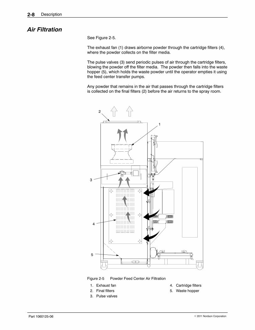
Air Filtration See Figure 2-5.
The exhaust fan (1) draws airborne powder through the cartridge filters (4),where the powder collects on the filter media.
The pulse valves (3) send periodic pulses of air through the cartridge filters,blowing the powder off the filter media. The powder then falls into the wastehopper (5), which holds the waste powder until the operator empties it usingthe feed center transfer pumps.
Any powder that remains in the air that passes through the cartridge filtersis collected on the final filters (2) before the air returns to the spray room.
1
3
4
5
23
8
5 4
10 9
3
8
5 4
10 9
2 1
7 6
2 1
7 6 678910
12345
678910
12345
Figure 2-5 Powder Feed Center Air Filtration
1. Exhaust fan2. Final filters3. Pulse valves
4. Cartridge filters5. Waste hopper

Description 2-9
Part 1060125-06� 2011 Nordson Corporation
Purge CycleSee Figure 2-4.
The operator starts a purge cycle either when changing colors or shuttingdown the system. When the purge cycle starts, the spray guns turn off andthe lance assembly (3) raises up out of the feed source. The operatorblows powder off the lance assembly, then removes the feed source (4)from the vibratory table (5).
The operator lowers the lance assembly until the pickup plates contact thepurge manifold (6). The purge manifold sends timed pulses of air throughthe pickup plates, powder pumps (2), powder feed hoses, and spray guns.
NOTE: Depending on how the feed center is configured, the purge cyclepurges each pump block assembly separately, or all pump block assembliesat the same time.
Powder Transfer System OperationRefer to your powder transfer system manual for a description of how thepowder transfer system operates.

Description2-10
Part 1060125-06 � 2011 Nordson Corporation
Powder Level Sensor Probe The powder feed center has one level sensor probe that controls the up anddown movement of the lance assembly. Feed centers that have the optionalbulk virgin powder feed system have a second level sensor that signals thebulk feed system to add powder to the feed source.
NOTE: The level sensor probe only operates when the Lance/Purge Modeis set to Auto.
The lance assembly stays at the fully up position until the operator selects afeed source by touching either the Select Box or Select Hopper button onthe operator interface. How the level sensor probe controls movement ofthe lance assembly depends on which feed source is selected.
Box Selected
NOTE: When you touch the Select Box button, its text changes toBOX Selected. If you touch the BOX Selected button during operation, thelance assembly will immediately move to the fully up position.
The feed center vibrator table turns on and the lance assembly lowers untilit contacts the surface of the powder in the box. As the level of powder inthe box goes down, the level sensor probe signals the lance assembly tolower until the contacts the powder surface.
When the powder in the box drops below a pre-set level, one of two thingshappen:
� If the feed center has the optional bulk virgin powder feed system, virginpowder will be automatically added to the box after a pre-set delay.
� If the feed center does not have the optional bulk virgin powder feedsystem, the low powder alarm timer delay starts. After the pre-set delayexpires, the alarm buzzer turns on and a low powder alarm conditionappears on the operator interface.
Hopper Selected
NOTE: When you touch the Select Hopper button, its text changes toHOPPER Selected. If you touch the HOPPER Selected button duringoperation, the lance assembly will immediately move to the fully up position.
The feed center vibrator table turns on for a pre-set period of time and thelance assembly lowers until it reaches a pre-set hopper limit position.
When the powder in the hopper reaches a level at which the level sensorprobe cannot sense it, one of two things happen:
� If the feed center has the optional bulk virgin powder feed system, virginpowder will be automatically added to the hopper after a pre-set delay.
� If the feed center does not have the optional bulk virgin powder feedsystem, the low powder alarm timer delay starts. After the pre-set delayexpires, the alarm buzzer turns on and a low powder alarm conditionappears on the operator interface.

Initial Setup 3-1
Part 1060125-06� 2011 Nordson Corporation
Section 3Initial Setup
WARNING: Allow only qualified personnel to perform the following tasks.Follow the safety instructions in this document and all other relateddocumentation.
Introduction This section explains how to set up the powder feed center to suit yourapplication requirements. The following topics are covered in this section:
Topic Description
User Access Levels Logging in to the feed center’s operator interface using one of threeaccess levels
System Configuration Identifying the hardware in your powder coating system
System Setup Setting the operating parameters for your
� Compressed Air System
� Powder Feed Center
� Spray Booth
� Powder Transfer System
Typical Operating Settings Setting the recommended air pressure and cartridge filter pulse timingvalues for the feed center
Level Sensor Programming Programming the level sensor probe to cause the lance assembly toraise or lower to the appropriate level in the powder feed source
These procedures need to be completed only when you start up the powderfeed center for the first time. After the initial configuration is completed andthe system is operating, you may also access the configuration menus tochange operating parameters.

Initial Setup3-2
Part 1060125-06 � 2011 Nordson Corporation
User Access Levels There are three user access levels. Not all users have access to adjust allfunctions of the powder feed center.
The user access level can be changed by touching the User Log-On buttonin the Special Functions area of the Main Menu or on either of theconfiguration screens. Refer to Table 3-1 for a list of the three user accesslevels and their passwords. The default user access level is Operator.
Touching Special Functions>User Log-Off switches the feed center toNo Operator status. You cannot change any operating or setup parameterswhen the feed center is in No Operator status.
Table 3-1 User Access Levels
User Access Level Password
Operator 0
Lead Operator 108
Supervisor 1597
System Configuration See FIgure 3-1. From the Special Functions menu, touch the SystemConfig button. The Feed Center Configuration menu appears.
Configure your feed center by touching the Yes/No buttons to identify thehardware in your feed center.
When you are finished with the settings on the Feed Center Configurationmenu, touch either
� Configuration Completed to exit the configuration setup, or
� Config System to go to the Spray System Configuration menu. TheSpray System Configuration menu allows you to specify the hardwareincluded in the spray booth.
Touch this button to view descriptions of the settings on thecurrent menu.

Initial Setup 3-3
Part 1060125-06� 2011 Nordson Corporation
Figure 3-1 System Configuration Menus

Initial Setup3-4
Part 1060125-06 � 2011 Nordson Corporation
System Setup See Screen 3-1. The Setup Menu displays buttons that open the foursetup menus.
Touch this button to view descriptions of the settings on thecurrent menu.
Screen 3-1 Setup Menu
Note: The Comp. Air button is optional.
Compressed Air Setup (Optional Feature) See Screen 3-2. From the Setup Menu, touch the Comp. Air button toshow the optional Compressed Air Setup menu.
Screen 3-2 Compressed Air Setup Menu

Initial Setup 3-5
Part 1060125-06� 2011 Nordson Corporation
Feed Center Setup See Figure 3-2. From the Setup Menu, touch the Feed Center button toshow the Feed Center Setup menu. Touch the Next and Previous buttonsto switch between the two Feed Center Setup menus.
Figure 3-2 Feed Center Setup Menus

Initial Setup3-6
Part 1060125-06 � 2011 Nordson Corporation
Spray Booth Setup See Screen 3-3. From the Setup Menu, touch the Spray Booth button toshow the Spray Booth Setup menu.
NOTE: Some of the settings on this menu are optional. They will onlyappear on systems that have an optional compressed air monitoringsystem.
Screen 3-3 Spray Booth Setup Menu
Powder Transfer System Setup From the Setup Menu, touch the Transfer button to show the PowderTransfer Setup menu.
NOTE: Refer to your powder transfer system manual for more informationabout setting up the powder transfer system.

Initial Setup 3-7
Part 1060125-06� 2011 Nordson Corporation
Typical Operating SettingsThe settings listed here are approximate. You may need to adjust thesesettings to obtain the desired results.
Operating Air PressuresRefer to Table 3-2 for a list of typical operating air pressures. Thesesettings are average starting points. You may need to adjust these settingsdepending on your application.
Table 3-2 Typical Operating Air Pressures
Air Pressure Setting
Input (Minimum) 6 bar (90 psi)
COLLECTOR PULSE 2.75 bar (40 psi)
COLLECTOR FLUIDIZE 0.5 bar (8 psi)
HOPPER FLUIDIZE 0.3 bar (5 psi)
COLLECTOR TRANSFER 2.75 bar (40 psi)
LANCE FLUIDIZE 0.3 bar (5 psi)
Cartridge Filter Pulse Valve Timing SettingsRefer to Table 3-3 for typical pulse valve timing settings. These settings areaverage starting points. You may need to adjust the settings if the feedcenter’s cartridge filters are not being pulsed sufficiently.
Table 3-3 Typical Pulse Valve Timer Board Settings
Timer Setting
Filter Pulse On Duration 0.07 seconds
Filter Pulse Off Duration 10 minutes

Initial Setup3-8
Part 1060125-06 � 2011 Nordson Corporation
Level Sensor Programming The level sensor probe #1 signals the lance assembly to lower to theappropriate level into a box of powder. An optional level sensor or probe #2signals the bulk powder transfer and low powder alarm. Follow theseprocedures to program the level sensor probe to recognize the level ofpowder in the feed source.
There are two different kinds of sensor probes that are identified by thenumber of programming buttons on the probe.
One Button Level Sensor Probe Programming When you program the level sensor probe, the powder feed center exhaustfan must be on and the Lance/Purge Mode must be set to Manual.
NOTE: Your system may have two level sensor probes. Perform thefollowing procedures for both probes.
PROGRAMMINGBUTTON
GREEN
REDYELLOW
Figure 3-3 Programming the One Button Level Sensor Probe
LED Functions LED Color Status Meaning
Green Lit continuously Ready for operation (power is on)
Yellow Lit continuously Output has switched (powder is detected; full condition)
Yellow andRed
Flashing quickly Short circuit of the switching output
Red Lit temporarily Normal function check; level sensor probe is approaching the fullstate
Lit continuously Level sensor probe is dirty or out of adjustment.

Initial Setup 3-9
Part 1060125-06� 2011 Nordson Corporation
Empty (no powder) Adjustment NOTE: Completing the Empty Adjustment overwrites the values set in theFull Adjustment. If you complete an Empty Adjustment, be sure to completea Full Adjustment.
1. Put a box or hopper of powder on the vibratory table.
2. From the Auto Menu, touch the LANCE DOWN button. Lower thelance assembly until the powder covers at least 25 mm (1 in.) of the tipof the level sensor probe.
3. From the Auto Menu, touch the LANCE UP button. Raise the lanceassembly so that the bottom of the level sensor is at least 25 mm (1 in.)away from the top level of the powder.
4. See Figure 3-3. Press the programming button until the green LEDflashes slowly. When the green LED stops flashing and the yellow LEDturns off, the empty adjustment is complete.
NOTE: If the programming button remains pressed after the green LEDflashes slowly, the green light will eventually start to flash quickly,signaling the programming for the Full Adjustment instead of the EmptyAdjustment. To correct the error in programming, repeat the steps fromthe beginning for programming the Empty Adjustment.
Full Adjustment NOTE: You may complete the Full Adjustment as often as you like withoutoverwriting the Empty Adjustment value.
1. Place a box or hopper of powder on the vibratory table.
2. From the Auto Menu, touch the LANCE DOWN button. Lower thelance assembly until the powder covers at least 25 mm (1 in.) of the tipof the level sensor probe.
3. See Figure 3-3. Press the programming button until the green LEDflashes quickly.
The green LED flashes slowly at first, then after five seconds it flashesquickly. When both the green and yellow LEDs are lit continuously, thefull adjustment is complete.

Initial Setup3-10
Part 1060125-06 � 2011 Nordson Corporation
Locking and Unlocking Adjustment The level sensor probe can be locked to protect it from unauthorizedadjustment. Use these guidelines to lock or unlock the level sensor probe.
NOTE: The level sensor probe is shipped from the factory in the unlockedstate.
Task Procedure
Locking Press the programming button for 10 seconds. The green LED will flashslowly for five seconds, then it will flash quickly.
When the green LED turns off, the level sensor probe is locked. Whenthe green LED turns back on continuously, the level sensor probe isready for operation.
Unlocking Press the programming button for 10 seconds. After 10 seconds, allLEDs turn off, indicating that the level sensor probe is unlocked.
Operational Faults (Red LED Flashing) If either the empty or full adjustment cannot be completed, the probe’s redLED flashes quickly.
Task Procedure
Clearing a Fault Clear the fault by either:
� pressing the programming button once, or
� turning off power to the feed center, then turning it back on again.
Correcting PossibleCauses for the Fault
Check for and correct any of these possible causes for the fault:
� The difference between the empty and full states is not great enough.
� The empty adjustment was completed while the level sensor probewas in the powder, or the full adjustment was completed while thelevel sensor probe was out of the powder.
� During the empty adjustment, the distance between the level sensorprobe and the powder was too short.

Initial Setup 3-11
Part 1060125-06� 2011 Nordson Corporation
Two Button Level Sensor Probe Programming When you program the level sensor probe, the powder feed center exhaustfan must be on and the Lance/Purge Mode must be set to Manual.
NOTE: Your system may have two level sensor probes. Perform thefollowing procedures for both probes.
OUT OFFProgramming Button
OUT ONProgramming Button
LED Ring
Figure 3-4 Programming the Two Button Level Sensor Probe
LED Functions for Operation LED Color Status Meaning
Green On Material not detected
Yellow On Material detected

Initial Setup3-12
Part 1060125-06 � 2011 Nordson Corporation
Empty Adjustment 1. Put a box or hopper of powder on the vibratory table.
2. From the Auto Menu, touch the LANCE DOWN button. Lower thelance assembly until the powder covers at least 25 mm (1 in.) of the tipof the level sensor probe.
3. From the Auto Menu, touch the LANCE UP button. Raise the lanceassembly so that the bottom of the level sensor is at least 25 mm (1 in.)away from the top level of the powder.
4. See Figure 3-4 Press the OUT OFF programming button until the LEDring slowly flashes yellow.
5. Release the button and the yellow light will go off. The emptyadjustment is complete.
Full Adjustment 1. Place a box or hopper of powder on the vibratory table.
2. From the Auto Menu, touch the LANCE DOWN button. Lower thelance assembly until the powder covers at least 25 mm (1 in.) of the tipof the level sensor probe and LED ring should light up yellow.
3. See Figure 3-4. Press the OUT ON programming button until the yellowlight from the LED ring goes from flashing slowly to flashing quickly.
4. Release the button and the LED ring lights yellow continuously. The fulladjustment is complete.

Initial Setup 3-13
Part 1060125-06� 2011 Nordson Corporation
Locking and Unlocking Adjustment The level sensor probe can be locked to protect it from unauthorizedadjustment. Use these guidelines to lock or unlock the level sensor probe.
NOTE: The level sensor probe is shipped from the factory in the unlockedstate.
Task Procedure
Locking Simultaneously press the two programming buttons for at 10 seconds inthe operating mode. Once the LED ring light changes its status for abrief moment, release the buttons, and the lock is complete.
Unlocking Simultaneously press the two programming buttons for at 10 seconds inthe operating mode. Once the LED ring light changes its status for abrief moment, release the buttons, and the unlock is complete.
Operational Faults If the sensor deviates from normal operation, use the following steps toreturn to normal operation.
Task Procedure
Return to NormalOperation
Check for and correct any of these possible causes for incorrectoperation:
� The difference between the empty and full states is not great enough.
� The empty adjustment was completed while the level sensor probewas in the powder, or the full adjustment was completed while thelevel sensor probe was out of the powder.
� During the empty adjustment, the distance between the level sensorprobe and the powder was too short.

Initial Setup3-14
Part 1060125-06 � 2011 Nordson Corporation

Operation 4-1
Part 1060125-06� 2011 Nordson Corporation
Section 4Operation
WARNING: Allow only qualified personnel to perform the following tasks.Follow the safety instructions in this document and all other relateddocumentation.
IntroductionNOTE: If you are using the powder feed center with a quick color changesystem, refer to your quick color change system manual for procedures foroperating the powder feed center with the system.
The PLC in the powder feed center control panel controls most of theautomatic processes in a typical system. Your Nordson applicationengineer typically programs and configures the PLC to suit your applicationrequirements.
NOTE: Your feed center may not have all of the functions that are identifiedin this section.
Operator Interface Menus The following paragraphs explain the functions of the basic menus thatappear on the feed center operator interface. The menus shown are typical.Your feed center menus may appear slightly different.
Touch this button to view descriptions of the settings on thecurrent menu.
When this button appears, touch it to view alarm messages.Refer to the Troubleshooting section for more information.

Operation4-2
Part 1060125-06 � 2011 Nordson Corporation
Main Menu See Screen 4-1 and refer to Table 4-1.
The Main Menu is the first menu that appears when you start up thepowder feed center for normal operation. Touching the buttons at thebottom of the menu allow you to access the feed center controls.
Screen 4-1 Main Menu
Table 4-1 Main Menu Buttons
Button Function
Comp. Air Status(optional feature)
Displays the current humidity, temperature, and dewpoint of the compressedair supply, if applicable.
Refer to Compressed Air Status on page 4-3.
Auto Displays the Auto Menu, where automatic functions are started and stopped.
Refer to Auto Menu on page 4-3.
Manual Displays the Manual Menu, which allows you to navigate to menus that allowmanual control of the feed center, spray booth, afterfilter, and gun blowofffunctions.
Refer to Manual Functions on page 4-4.
Setup Displays the Setup Menu, which allows you to set operating parameters forthe feed center.
Refer to the Initial Setup section.
Special Functions Displays the Special Functions Menu, which allows you to set the types ofhardware in the feed center, view the alarm log, and log on or off.
Refer to the Initial Setup section.
Booth Move(optional feature)
Displays the Booth Move Control menu, which allows you to move thepowder spray booth on and off line, if applicable.
Refer to Booth Move on page 4-5.

Operation 4-3
Part 1060125-06� 2011 Nordson Corporation
Compressed Air Status (Optional Feature) See Screen 4-3. The Compressed Air Dewpoint menu shows the statusof the powder feed center air supply.
Screen 4-2 Compressed Air Status Menu
Auto Menu See Screen 4-3. The Auto Menu allows the operator to control theautomated functions of the powder feed center.
Screen 4-3 Auto Menu

Operation4-4
Part 1060125-06 � 2011 Nordson Corporation
Manual FunctionsSee Figure 4-5. Your system may have other manual functions. Refer toyour powder coating system manual for information about functions notexplained in this manual.
Refer to your powder transfer systemmanual for more information
Optional Feature
Optional Feature
Optional Feature
Optional Feature
Figure 4-5 Manual Feed Center Control Menus

Operation 4-5
Part 1060125-06� 2011 Nordson Corporation
Booth MoveSee Screen 4-3. Refer to Booth Moving on page 4-10 for instructions forusing the Booth Move Control menu.
NOTE: The Booth Move Control menu is only included with feed centersthat are part of a roll-on/roll-off powder coating system in which the afterfilterassembly does not roll with the spray booth.
Screen 4-4 Booth Move Control Menu

Operation4-6
Part 1060125-06 � 2011 Nordson Corporation
Security SystemYou must log on to the powder feed center operator interface before youmay operate the powder feed center.
There are three user access levels. Not all users have access to adjust allfunctions of the powder feed center.
Logging On See Screen 4-5. Touch the User Log-On button on the Special FunctionsMenu to log on to the powder feed center. Refer to Table 4-2 for a list of thethree user access levels and their passwords. The default user accesslevel is Operator.
Table 4-2 User Access Levels
User Access Level Password
Operator 0
Lead Operator 108
Supervisor 1597
Logging Off Touch Special Functions>User Log-Off switches the feed center toNo Operator status. You cannot change any operating or setup parameterswhen the feed center is in No Operator status. If there is no activity on theoperator interface for 60 minutes, the current operator will be automaticallylogged off.
Screen 4-5 Logging On and Logging Off: Special Functions Menu

Operation 4-7
Part 1060125-06� 2011 Nordson Corporation
Daily Startup NOTE: These procedures assume that the powder coating system(including the feed center) has been cleaned and is in the online position.
1. Turn the powder feed center control panel disconnect switch to the onposition.
2. See Screen 4-6. From the Auto Menu, touch the SYSTEM STARTbutton. All of the components of the powder coating system turn on.
3. Install the appropriate feed source. Refer to Powder Feed SourceInstallation for instructions on installing the feed source.
NOTE: Make sure that the Lance/Purge Mode is set to AUTO.
4. Touch the Select Box or Select Hopper button to match the feedsource installed. The button text will change to either BOX Selected orHOPPER Selected and the lance assembly will move down to theposition appropriate for the feed source.

Operation4-8
Part 1060125-06 � 2011 Nordson Corporation
Screen 4-6 Auto Menu
5. Adjust the fluidizing air pressure:
� Powder Box: Adjust the needle valve on the lance assembly.
� Fluidizing Hopper: Adjust the fluidizing air at the powder feedcenter pneumatic panel. (Recommended setting: 0.3 bar (5 psi))
6. Enable the following functions (as applicable):
Button Function
Enable Powder Transfer Enables the powder transfer system
Enable Reclaim Transfer Reclaims oversprayed powder as it collectsin the transfer pan
Enable Virgin Transfer Enables the optional bulk virgin powderfeed system
Enable Vibrasonic Enables the optional Vibrasonic sievescreen
7. Start spraying powder. Refer to your gun control system manual forinformation about gun triggering.

Operation 4-9
Part 1060125-06� 2011 Nordson Corporation
Powder Feed Source InstallationUse one of the following procedures to install a powder feed source into thepowder feed center.
Powder Box Installation1. On the Auto Menu, set the Lance/Purge Mode to MANUAL.
2. Touch the LANCE UP button to raise the lance assembly.
3. Open the box of powder and place it on the vibratory table.
4. Make sure that the box is centered under the lance assembly, thensecure the box to the vibratory table using the box guides and clampinglevers.
5. Touch the Select Box button. The button’s text changes toBOX Selected.
6. Set the Lance/Purge Mode to AUTO.
When all feed center modes are set to AUTO, the lance assembly lowers asthe powder level falls. When the level sensor senses that the lanceassembly has lowered below the box limit, the sensor activates control foreither a low-powder alarm or automatic bulk feed.
Fluidizing Hopper Installation1. On the Auto Menu, set the Lance/Purge Mode to MANUAL.
2. Touch the LANCE UP button to raise the lance assembly.
3. Remove the front box guide from the vibratory table and set it aside.
4. Place the hopper on the vibratory table. Make sure that the hopper iscentered under the lance assembly, then remove the lid from the hopper.
5. Connect the fluidizing air tubing to the air fitting on the hopper.
NOTE: Adjust the fluidizing air pressure at the feed center pneumaticpanel as necessary.
6. Touch the Select Hopper button. The button’s text changes toHOPPER Selected.
7. Set the Lance/Purge Mode to AUTO.
When all feed center modes are set to AUTO, the lance assembly lowers tothe hopper limit position and stays there. If the optional bulk feed levelsensor does not sense powder, the sensor activates control for alow-powder alarm or automatic bulk feed.
Color Change Refer to your powder transfer system manual for color change procedures.

Operation4-10
Part 1060125-06 � 2011 Nordson Corporation
Booth Moving (Optional Feature) See Screen 4-7. The cyclone disconnect is the device that closes the spacebetween cyclone outlet and the duct that leads into the afterfilter. The ductdampers direct the airflow into the afterfilter from either the online or offlineposition of the booth.
The booth mover and dampers are interlocked using limit switches so thatthe booth cannot be moved if the cyclone disconnect is in the closedposition.
The cyclone disconnect and duct dampers may be controlled eitherautomatically or manually, depending on how the Cyclone Disc. DuctDampers Mode button is set.
Screen 4-7 Booth Move Control Menu

Operation 4-11
Part 1060125-06� 2011 Nordson Corporation
Auto Mode Operation: Booth Move Control NOTE: See Screen 4-7. Make sure the Cyclone Disc. Duct DampersMode button is set to AUTO.
1. Press the Mover Enable button on the main booth electrical panel. Thiscauses the following things to happen:
� The booth mover buzzer emits short, fast beeps
� The cyclone disconnect opens
� The Ready to Move Booth and Cyclone Disc. Closed indicatorson the Booth Move Control menu will light
� The booth mover is enabled
2. Press and hold the appropriate Booth Move direction button on thependant connected to the main booth electrical panel. As the boothmoves, the booth mover buzzer will emit long, slow beeps.
3. When the booth reaches the end of its travel, release the Booth Movedirection button. The Booth at Off-line Position or Booth at On-linePosition indicator will light.
4. Press the Mover Enable button on the main booth electrical panel todisable the booth mover and close the cyclone disconnect.
Manual Mode Operation: Booth Move Control NOTE: See Screen 4-7. Make sure the Cyclone Disc. Duct DampersMode button is set to MANUAL.
1. Touch the CYCLONE DISC. OPEN button on the Booth Move Controlmenu. Ready to Move Booth indicator will light.
2. Press the Mover Enable button on the main booth electrical panel. Thiscauses the following things to happen:
� The booth mover buzzer emits short, fast beeps
� The booth mover is enabled
3. Press and hold the appropriate Booth Move direction button on thependant connected to the main booth electrical panel. As the boothmoves, the booth mover buzzer will emit long, slow beeps.
4. When the booth reaches the end of its travel, release the Booth Movedirection button. The Booth at Off-line Position or Booth at On-linePosition indicator will light.
5. Touch the CYCLONE DISC. CLOSE button on the Booth Move Controlmenu. The Cyclone Disc. Closed indicator will light.
Operation4-12
Part 1060125-06 � 2011 Nordson Corporation
Shutdown1. Move the system offline, if applicable. Refer to Booth Moving on
page 4-10.
2. Clean the system by performing the color change process, but do notinstall a new powder source. Refer to your powder transfer systemmanual for instructions.
NOTE: If you are shutting down the system for a short break in production,do not perform steps 3 or 4.
3. See Screen 4-6. From the Auto Menu, touch the SYSTEM STOPbutton. All components in the powder coating system turn off.
4. If you will be shutting down the powder feed center for maintenance,repair, or an extended period of time, perform these steps:
a. Press the SYSTEM STOP button on the system control panel.
b. Turn the electrical disconnect switch on the powder feed centercontrol panel to the off position.
Maintenance 5-1
Part 1060125-06� 2011 Nordson Corporation
Section 5Maintenance
WARNING: Allow only qualified personnel to perform the following tasks.Follow the safety instructions in this document and all other relateddocumentation.
Daily MaintenanceNOTE: You may need to perform these procedures more or less often,depending on your application requirements.
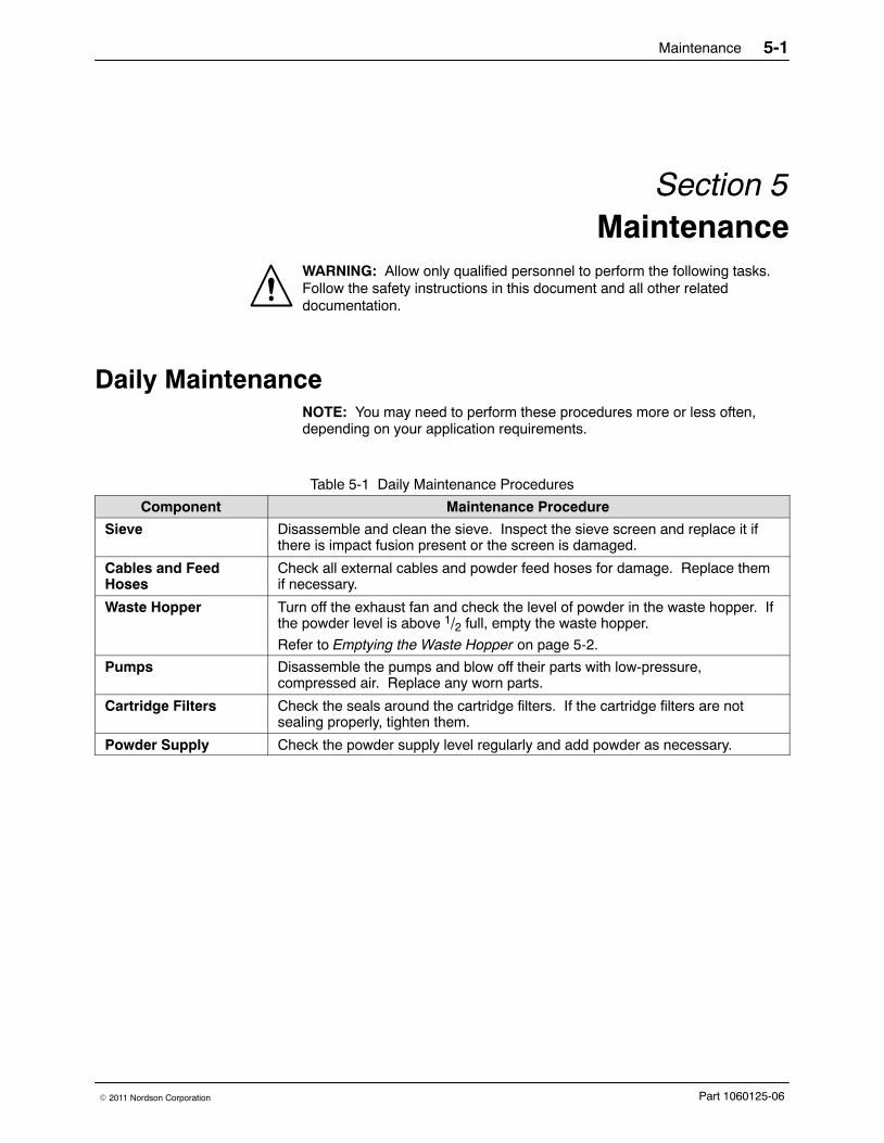
Table 5-1 Daily Maintenance Procedures
Component Maintenance Procedure
Sieve Disassemble and clean the sieve. Inspect the sieve screen and replace it ifthere is impact fusion present or the screen is damaged.
Cables and FeedHoses
Check all external cables and powder feed hoses for damage. Replace themif necessary.
Waste Hopper Turn off the exhaust fan and check the level of powder in the waste hopper. Ifthe powder level is above 1/2 full, empty the waste hopper.
Refer to Emptying the Waste Hopper on page 5-2.
Pumps Disassemble the pumps and blow off their parts with low-pressure,compressed air. Replace any worn parts.
Cartridge Filters Check the seals around the cartridge filters. If the cartridge filters are notsealing properly, tighten them.
Powder Supply Check the powder supply level regularly and add powder as necessary.

Maintenance5-2
Part 1060125-06 � 2011 Nordson Corporation
Emptying the Waste HopperNOTE: You may choose to have a single, shared scrap drum for the feedcenter and the booth after filter. In this application, the scrap transfer hosemay remain connected to the scrap drum at all times, allowing you tofrequently empty the feed center waste hopper to keep the powder leveldown.
1. See Figure 5-1. Secure the waste lid to an empty 55-gallon drum (3).
2. Connect the ground clamp (4) to a true earth ground.
3. Attach a 3/4-in. transfer hose (2) between the transfer pumps (5) and thewaste lid. Use hose clamps on both ends of the transfer hose.
NOTE: Make sure that all unused hose connectors on the waste lid areplugged.
4. Attach the vent hose (1) to the waste lid vent stub. Attach the other endof the vent hose to the vent stub (6) on the feed center.
5. Touch the WASTE PUMPS START button on the Manual Feed CenterControl, page 1 menu. The fluidizing and flow air will turn on and thepowder will be drawn out of the waste hopper.
NOTE: The normal operating air pressure for the transfer pump is 2.75 bar(40 psi). The normal fluidizing air pressure is 0.5 bar (8 psi). Adjust the airpressures as needed at the feed center control panel.
6. When the transfer pump is not drawing any more powder out of thewaste hopper, touch the WASTE PUMPS STOP button.
NOTE: The waste transfer process will automatically stop after severalminutes. The duration of the waste transfer process may be changed onthe Feed Center Setup menu.

Maintenance 5-3
Part 1060125-06� 2011 Nordson Corporation
1
3
6
5
4
2
Figure 5-1 Emptying the Waste Hopper
1. Vent hose2. 3/4-in. Transfer hoses
3. Scrap drum with lid4. Ground clamp
5. Transfer pump6. Feed center vent stub

Maintenance5-4
Part 1060125-06 � 2011 Nordson Corporation
Periodic MaintenanceNOTE: You may need to perform these procedures more or less often,depending on your application requirements.
Table 5-2 Periodic Maintenance Procedures
Component Maintenance Procedure
Airflow Take regular airflow readings. A properly functioning powder feed centershould provide a face velocity of around 125 fpm. A lower reading indicatesclogged filters or a malfunctioning fan.
Fan Motor Perform the following checks regularly. Problems will be apparent if you noticechanges in the following factors.
� Pay attention to changes in vibration and noise levels.
� Take current readings regularly.
� Check all electrical connections regularly.
Cartridge Filters/FinalFilters
Check the differential pressure gauges on the pneumatic panel.
� Cartridge Filters: pulsing on demand at 3-in. wc
� Final Filters: warning at 4-in. wc; shutdown at 5-in. wc
Check all filters and replace them if necessary.
Remove the final filters and inspect the fan housing. Signs of powder insidethe fan section indicate a leaking cartridge filter.
Compressed AirSystem
Open the drop leg and use a clean, white cloth to check for contaminants.Correct any problems immediately.
Electrical System Tighten all electrical connections and inspect for loose or broken wires.
Check the electrical system for electrical safety every 12 months. The systemmust comply with all local, state, and federal codes.

Troubleshooting 6-1
Part 1060125-06� 2011 Nordson Corporation
Section 6Troubleshooting
WARNING: Allow only qualified personnel to perform the following tasks.Follow the safety instructions in this document and all other relateddocumentation.
This section contains troubleshooting procedures. These procedures coveronly the most common problems that you may encounter. If you cannotsolve the problem with the information given here, contact your localNordson representative for help.
Table 6-1 Powder Supply Problems
No. Problem Page
1. Spray guns are surging or spitting; powder flow isinadequate or intermittent
6-3
2. Powder in feed source contaminated 6-3
3. Powder in feed source not fluidizing, or clouds ofpowder erupting from surface
6-3
4. Powder escaping from enclosure openings 6-4
Table 6-2 Color Change Problems
No. Problem Page
1. Purge cycle will not start 6-5
2. Guns’ external blowoff cycle will not start 6-5
3. Purge air does not activate for all purge manifolds 6-5
Table 6-3 Sieve Problems
No. Problem Page
1. Vibrator does not start 6-8
2. Powder build up on sieve mesh 6-8
3. Excessive sieve noise 6-8
4. Contaminants in powder in feed source 6-8

Troubleshooting6-2
Part 1060125-06 � 2011 Nordson Corporation
Table 6-4 Filter Section Problems
No. Problem Page
1. Fan will not start 6-9
2. Loss of extraction 6-9
3. Final filters clogged; powder in the fan section 6-9
4. Fan stops unexpectedly 6-9
Table 6-5 Other Problems
No. Problem Page
1. Vibratory table will not start 6-10
2. No or limited response to commands from operatorinterface
6-10
3. No display at operator interface 6-10

Troubleshooting 6-3
Part 1060125-06� 2011 Nordson Corporation
Powder Supply Problems
Problem Possible Cause Corrective Action
1. Spray guns aresurging or spitting;powder flow isinadequate orintermittent
Insufficient air volume in feedhose; powder is settling out
Increase the atomizing air pressureand decrease the flow rate airpressure. Refer to the spray gun andcontrol unit manuals forrecommended air pressures andratios.
Powder in feed sourceinadequately fluidized; cavitiesforming in powder below pickuptube ends
Adjust the fluidizing air pressure. Thepowder should be gently boiling.Refer to problem 3.
Low powder level in feed source Add powder to the feed source.Refer to problem 3.
Powder pump venturi nozzles orthroats worn; pickup tube suckingair at connection to pump mountingarm; pump or pickup tube clogged
Clean the pump and pickup tube.Replace any worn parts. Replaceany damaged O-rings.
Obstruction in powder feed hose Disconnect the feed hose from thepump. Blow the powder out of thehose with compressed air. Make surethe hose is clear. Eliminate kinks orsevere bends in the hose. The hoseshould be no longer than 7.6 m (25 ft)with a maximum 2.7-m (9-ft) verticalrise.
Severe tribo-charging in powderfeed hose
Contact your Nordson Corporationrepresentative for a suitable hosematerial. Contact your powdersupplier.
Obstruction in spray gun Clean the spray gun. If you are usingconical nozzles, make sure there is a3 mm (0.125 in.) or larger gapbetween the deflector and the nozzle.
2. Powder in feedsource contaminated
Sieve screen damaged Replace the sieve screen.
Sieve screen not thoroughlycleaned before installation
Remove and clean the sieve screen.
3. Powder in feedsource not fluidizing,or clouds of powdererupting from surface
Fluidizing air pressure too low ortoo high
Check the powder in the feed source.Increase the fluidizing air pressureuntil the powder is gently boiling.Decrease the pressure if clouds ofpowder are erupting from the surface.
Moist or oil-contaminated powder Open the drain valve at the air-supplydrop leg and check the air supply forwater or oil. Check the filters,separators, and air dryer.
Replace the powder in the feedsource. Refer to the next possiblecause.
Continued...

Troubleshooting6-4
Part 1060125-06 � 2011 Nordson Corporation
Corrective ActionPossible CauseProblem
3. Powder in feedsource not fluidizing,or clouds of powdererupting from surface (contd)
Systems with fluidizing hopperonly: Fluidizing plate gasketleaking, or fluidizing plate plugged,cracked, or installed incorrectly
Check for air leaks around thefluidizing plate gaskets. If leaks arefound, remove the plate and replacethe gasket.
Remove the fluidizing plate from thefluidizing box. Inspect it for stains,discoloration, polished surfaces, orcracks. Replace the fluidizing plate ifit is contaminated, plugged, ordamaged. Plate should be installedwith smooth surface up (in contactwith powder).
Incorrect ratio of reclaimed-to-newpowder
Increase or decrease the transferrate. Add new powder to feedsource. The powder supply shouldbe no more than three partsreclaim-to-one part new powder.
Uneven distribution of powder infeed source
Check the powder and the fluidizingplate for contamination as previouslydescribed.
Vibratory table isolator mountsloose or damaged
Inspect the vibratory table isolatormounts. Tighten or replace them asnecessary. Refer to Vibratory TableIsolator Mount Replacement in theRepair section.
4. Powder escapingfrom enclosureopenings
Cartridge filters clogged; exhaustfan draw insufficient to retainpowder within enclosure
Check the cartridge filter pulsesequence and pulse the cartridgefilters for 30 minutes. Replace thecartridge filters if necessary.
Cross drafts interfering withexhaust fan draw
Check for cross drafts at theenclosure opening. Eliminate ordivert drafts.
Fan rotation backward Reverse the rotation of the motor.Refer to the Reversing MotorDirection procedure in this section.
Access panels not sealed Tighten all access panels. Check andreplace the panel gaskets asnecessary.
Cartridge filters leaking Check the cartridge filter mountingseal. Tighten or replace thecartridge.
Check the cartridge filters forpunctures. Replace as necessary.
Powder feed hose leak Check the powder feed hose for leaksor damage. Replace as necessary.
Powder pump leak Check all pump O-rings. Replaceany damaged O-rings.
Gaps in enclosure seams orgaskets
Caulk seams or replace gaskets.

Troubleshooting 6-5
Part 1060125-06� 2011 Nordson Corporation
Color Change Problems
Problem Possible Cause Corrective Action
1. Lance moved down,but purge cycle willnot start
Purge limit sensor and stop boltsout of alignment
Realign the sensor and stop boltsusing the Purge Position Sensor andStop Bolt Realignment procedure.
External gun blowoff cycle notcompleted
Refer to the Color Change section ofyour powder transfer system manualfor the correct color changesequence.
Check the motor and drivecomponents of the gun movers
Purge limit switch at gun movertripped before purge cycle starts
Check gun mover purge limit switchalignment.
Purge cycle disabled Enable the system using either theOPERATION keyswitch on the mainsystem electrical panel.
2. Guns’ externalblowoff cycle will notstart
Oscillator not at bottom of stroke;proximity sensor not on
The oscillator’s bottom of strokeproximity sensor must be turned onfor the entire color change cycle.
Check that the oscillator is stopped atthe bottom of stroke and that thesensor is on. (Check the manualSpray Booth Control screen. SeeFigure 4-5.)
Check the mounting position of theproximity sensor. The sensor shouldbe adjusted to position its face within1/8 in. of the surface to be detected.Check connections at the sensor andsensor cable.
Gun mover disabled Enable the gun mover using eitherthe OPERATION keyswitch on themain system electrical panel or theiControl system.
3. Purge air does notactivate for all purgemanifolds
Feed center configuration incorrect See FIgure 3-1. Go to the FeedCenter Configuration menu and setthe number of purge valves to thecorrect number.
Purge valve failure There is one purge valve per purgemanifold. Check the purge valveoperation and wiring.
WARNING: High airpressure. Use caution whenservicing or actuating thepurge valves.

Troubleshooting6-6
Part 1060125-06 � 2011 Nordson Corporation
Purge Position Sensor and Stop Bolt Realignment See Figure 6-1.
1. Remove the feed source from the powder feed center.
2. From the Color Change menu, touch the Lance/Purge Mode button sothat it displays MANUAL.
NOTE: To ensure that all lance assemblies will lower to the same location,make the same adjustments to both stop bolts.
3. Touch the LANCE DOWN button to lower the lance assembly. Lowerthe lance assembly until the pickup plates (9) fully engage with thepurge manifolds (10).
If the pickup plates do not engage the purge manifolds, turn both stopbolts (8) clockwise one turn and touch the LANCE DOWN button again.Repeat if necessary.
4. Turn both stop bolts counterclockwise until their heads are firmly againstthe bottom of the linear slide (6). When both stop bolts are firmly inplace, lock them into position using the jam nuts (7).
NOTE: Figure 6-1 shows the typical locations of the three sensors on thecylinder rod. Use these dimensions only as a starting point for aligning thesensors.
5. Loosen the sensor bracket (4) and slide it up and down the cylinder roduntil the LED (5) illuminates. With the LED illuminated, tighten thesensor bracket.
6. Use the LANCE UP/DOWN buttons to make sure that the sensor LEDilluminates when the pickup plates engage the purge manifolds.Readjust the stop bolts and sensor if necessary.

Troubleshooting 6-7
Part 1060125-06� 2011 Nordson Corporation
1
2
3
4
5
6
7
8
9
10
187 mm(7 in.)
center of light102 mm(4 in.)
center of light
279 mm(11 in.)
center of light
7
8
Figure 6-1 Purge Position Sensor and Stop Bolt Realignment
1. Hopper stop sensor2. Box stop sensor3. Purge position sensor4. Sensor bracket
5. Sensor LED6. Linear slide7. Jam nuts
8. Stop bolts9. Pickup plate
10. Purge manifold

Troubleshooting6-8
Part 1060125-06 � 2011 Nordson Corporation
Sieve Problems
Problem Possible Cause Corrective Action
1. Vibrator does notstart
Power is off Turn on the power supply.
Fuse failure Replace any blown fuses.
Overload activated Reset the overload.
Wiring fault Check the motor wiring. Repair orreplace wiring as necessary.
Motor failure Check the motor. Replace the motorif necessary.
Contactor fault Repair or replace the motor contactor.
2. Powder build up onsieve mesh
Mesh not cleaned frequentlyenough
Clean the sieve mesh at morefrequent intervals. Upgrade toVibrasonic sieve screen if necessary.
Mesh size too small for powderbeing used
Use a sieve screen with a largermesh size. Upgrade to Vibrasonicsieve screen if necessary.
3. Excessive sieve noise Sieve deck or underpan not secure Tighten the clamps securing the sievedeck and underpan to the sieve.
Knobs or clamps not tightened;isolators loose or damaged; rubbersleeves damaged
Make sure the clamps are tight.Check the isolators for looseness ordamage. Tighten the isolatormounting screws. Check the rubbersleeves for damage and replace themif necessary.
4. Contaminants inpowder in feed source
Sieve screen torn Replace the screen.

Troubleshooting 6-9
Part 1060125-06� 2011 Nordson Corporation
Filter Section Problems
Problem Possible Cause Corrective Action
1. Fan will not start Power is off Turn on the power supply.
Fuse failure Replace any blown fuses.
Motor overload protector tripped Reset the overload protector.
Wiring fault Check the motor wiring. Repair orreplace wiring as necessary.
Motor failure Check the motor. Replace the motorif necessary.
Contactor fault Repair or replace the motor contactor.
2. Loss of extraction Cartridge filters clogged Check the cartridge filter pulsesequence and pulse the cartridgefilters for 30 minutes. Replace thecartridge filters if necessary.
Pulse pressure too low Set the pulse air pressure to 2.75 bar(40 psi).
Pulse valve fault Replace the pulse valve.
3. Final filters clogged;powder in the fansection
Leaking cartridge filter gaskets, ordamaged filter media
Make sure the gaskets are sealingcorrectly. If you can slip a 0.4-mm(0.015-in.) feeler gauge between thegasket and the sealing surface,tighten the mounting nuts tocompress the gaskets.
If the gaskets continue to leak,remove the cartridges. Clean andinspect the gaskets, sealing surfaces,and filter media. Replace thecartridges if the gaskets or filtermedia are damaged. Replaceclogged final filters.
Refer to Cartridge Filter Replacementin the Repair section for instructions.
4. Fan stopsunexpectedly
Final filter pressure too high The final filter pressure switch isdetecting abnormal pressure at thefinal filters. Refer to Problem 3 in thistable.

Troubleshooting6-10
Part 1060125-06 � 2011 Nordson Corporation
Other Problems
Problem Possible Cause Corrective Action
1. Vibratory table willnot start
Power is off Turn on the power supply.
Fuse failure Replace any blown fuses.
Motor overload protector tripped Reset the overload protector.
Wiring fault Check the motor wiring. Repair orreplace wiring as necessary.
Motor failure Check the motor. Replace the motorif necessary.
Contactor fault Repair or replace the motor contactor.
Vibratory table not required forselected operation
When the hopper feed source isselected, the vibratory table is on foronly a short time.
2. No or limitedresponse tocommands fromoperator interface
Communication lost betweenoperator interface and feed centerPLC
Check the cable connectionsbetween the operator interface andthe PLC. Refer to the Control PanelDiagrams section in this manual.
Operator interface /PLCcommunication module problem
The communication module connectsthe operator interface to the PLC.LEDs on the module indicate itsstatus. If the LEDs are not lit, contactNordson Customer Support.
BYPASS keyswitch not in the OFFposition
The BYPASS keyswitch is located inthe feed center electrical panel toprovide limited operation of the feedcenter if the operator interface fails.
Make sure the BYPASS keyswitch isin the OFF position.
3. No display at theoperator interface
No input power Check the power supply to the feedcenter electrical panel.
No 24 VDC power Check the feed center electrical panel24 VDC power supply and its circuitprotector.
Check the 24 VDC wiring andconnections to the operator interface.
Operator interface failure Replace the operator interface.Nordson-specific program softwaremust be installed. Contact NordsonCustomer Support.

Repair 7-1
Part 1060125-06� 2011 Nordson Corporation
Section 7Repair
WARNING: Allow only qualified personnel to perform the following tasks.Follow the safety instructions in this document and all other relateddocumentation.
IntroductionWARNING: Relieve system air pressure and lock out the air supply beforeperforming the following tasks. Failure to observe this warning may result inpersonal injury.
This section contains basic repair instructions for the powder feed center.Repair procedures for other system components are covered in their own,separate manuals.
NOTE: Contact your Nordson representative about any powder feed centerrepair procedures that are not covered in this section.
Cartridge Filter ReplacementNOTE: Two people are required to replace the cartridge filters. One personremoves hardware from above the cartridge filter. The other personremoves the old filters and holds the new filters up against the mountingplate.

Repair7-2
Part 1060125-06 � 2011 Nordson Corporation
Removing the Cartridge FilterSee Figure 7-1.
WARNING: Relieve system air pressure and lock out the air supply beforeperforming the following tasks. Failure to observe this warning may result inpersonal injury.
1. Remove the pulse valve and cartridge filter access panels (1, 2).
2. Pull up on the T-handle on the draw rod (8) to hold the cartridgefilter (10) against the mounting plate (7).
3. Remove the nut, lock washer, flat washer, and mounting bracket (3, 4, 5, 6) from the draw rod. Save these parts for reuse.
4. Carefully lower the cartridge filter away from the mounting plate and outof the filter section. The centering bracket (9) and draw rod will stay inplace.
5. Unscrew the draw rod and remove the draw rod and centering bracketfrom the old cartridge filter.
Installing the Cartridge FilterSee Figure 7-1.
1. Thoroughly clean the sealing surface on the underside of the mountingplate (7). A dirty surface will prevent the cartridge filter gasket fromsealing properly and allow powder to leak into the fan section.
2. Remove the new cartridge filter (10) from its carton and inspect it fordamage. Do not use damaged cartridge filters.
3. Set the centering bracket (9) into the open end of the new cartridge filter.Slide the draw rod (8) through the centering bracket. Screw the drawrod into the bottom of the cartridge filter.
4. Center the cartridge filter under the opening in the mounting plate. Usethe draw rod T-handle to pull up the cartridge filter against the mountingplate.
5. Install the mounting bracket (6) on the draw rod, making sure that theslots in the mounting bracket slip over the T-handle.
6. Install the flat washer, lock washer, and nut (5, 4, 3) onto the draw rod.Do not tighten the nut at this time.
7. Slip the ends of the mounting bracket into the locating slots around thefilter opening in the mounting plate.
8. Tighten the nut until the mounting and centering brackets are touching.This will compress the gasket (11) and seal the cartridge against themounting plate.
9. Install the pulse valve and cartridge filter access panels (1, 2).
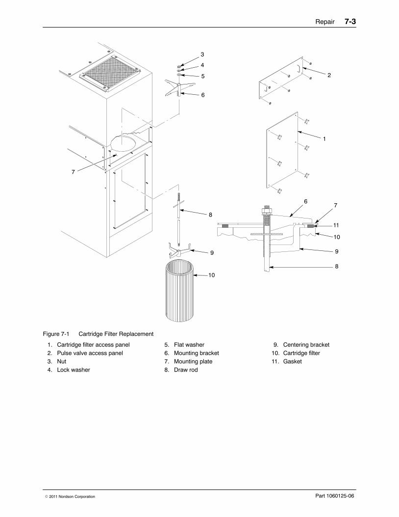
Repair 7-3
Part 1060125-06� 2011 Nordson Corporation
2
3
4
5
6
8
9
10
67
11
10
9
8
7
1
Figure 7-1 Cartridge Filter Replacement
1. Cartridge filter access panel2. Pulse valve access panel3. Nut4. Lock washer
5. Flat washer6. Mounting bracket7. Mounting plate8. Draw rod
9. Centering bracket10. Cartridge filter11. Gasket

Repair7-4
Part 1060125-06 � 2011 Nordson Corporation
Final Filter ReplacementWARNING: Relieve system air pressure and lock out the air supply beforeperforming the following tasks. Failure to observe this warning may result inpersonal injury.
1. See Figure 7-2. Remove the final filter brackets (1).
2. Pull the old final filter (2) out of the powder feed center.
3. Inspect the inside of the fan housing. Vacuum out any powder that hasaccumulated inside the housing.
NOTE: If powder has accumulated inside the fan housing, check thecartridge filter media and gaskets. Tighten the cartridge filters’ mountinghardware to compress the gaskets or replace the cartridge filters.
4. Remove the new final filter from its carton and inspect it for damage. Donot use damaged final filters.
5. Place the new final filter into the powder feed center.
6. Install the final filter brackets.
7. Tighten the bracket nuts to compress the final filter evenly on all foursides.
2
1
Figure 7-2 Final Filter Replacement
1. Brackets 2. Final filter

Repair 7-5
Part 1060125-06� 2011 Nordson Corporation
Pulse Valve ReplacementNOTE: Replace the pulse valves one at a time to avoid confusing which airtubing connects to which pulse valve.
WARNING: Relieve system air pressure and lock out the air supply beforeperforming the following tasks. Failure to observe this warning may result inpersonal injury.
1. Relieve system air pressure and lock out the air supply.
2. See Figure 7-3. Remove the pulse valve access panel (5).
3. Disconnect the air tubing from the pulse valve’s elbow fitting (2).
4. Unscrew the pulse valve (3) from the nipple (1).
5. Remove the nozzle (4) and elbow from the pulse valve.
6. Clean the threads of the nozzle, elbow, and nipple and wrap the threadswith 2−3 layers of new PTFE tape.
7. Install the nozzle and elbow onto the new pulse valve.
8. Install the new pulse valve onto the nipple. Make sure that the pulsevalve nozzle points straight down into the center of the cartridge filter.
9. Connect the air tubing to the elbow.
10. Install the pulse valve access panel and turn on system air pressure.
52
1 3
4
Figure 7-3 Pulse Valve Replacement
1. Nipple2. Elbow3. Pulse valve
4. Nozzle5. Pulse valve access panel

Repair7-6
Part 1060125-06 � 2011 Nordson Corporation
Waste Hopper Fluidizing Plate Replacement1. Empty as much powder as possible from the waste hopper. Refer to
Emptying the Waste Hopper in the Maintenance section for moreinformation.
2. See Figure 7-4. Remove the cartridge filter access panels (6) andvacuum out any remaining powder in the waste hopper.
3. Turn off and lock out power to the powder feed center.
NOTE: The retaining angles (4) secure the fluidizing plate (5) to the bottomof the waste hopper.
4. Remove the M6 screws (1), lock washers (2), and flat washers (3)securing the six retaining angles (4) to the fluid section.
5. Remove the retaining angles and fluidizing plate (5) from the wastehopper.
6. Set the new fluidizing plate smooth side up into the waste hopper.
7. Set the retaining angles on top of the fluidizing plate.
NOTE: As you tighten the retaining angles, push down on them tocompress the fluidizing plate gasket evenly.
8. Secure the retaining angles and fluidizing plate to the waste hopperusing the screws, lock washers, and flat washers.

Repair 7-7
Part 1060125-06� 2011 Nordson Corporation
5
4
1
2 3
6
Figure 7-4 Waste Hopper Fluidizing Plate Replacement
1. Screws (M6 x 1 in.)2. Lock washers (M6)
3. Flat washers (M6)4. Retaining angles
5. Fluidizing plate6. Cartridge filter access panel

Repair7-8
Part 1060125-06 � 2011 Nordson Corporation
Vibratory Table Isolator Mount Replacement 1. See Figure 7-5. Remove both box guides (3) from the vibratory table (4)
and set them aside.
2. Remove the four socket-head cap screws and lock washers (1) securingthe vibrator motor (2) to the vibratory table.
3. Carefully remove the vibrator motor and set it at the back of the feedcenter.
4. Remove the kick plate (7) on the bottom front of the feed center byremoving the five screws (8).
5. Remove the four 5/16-18 flange nuts (9) securing the vibratory table tothe feed center floor (6).
6. Carefully lift the vibratory table out of the feed center and stand it up onits front edge.
7. Unscrew the four isolator mounts (5) from the vibratory table.
8. Install new isolator mounts onto the vibratory table and follow steps 1−6in reverse to install the vibratory table into the feed center.
2
1
3
4
5 67
8
99
Figure 7-5 Vibratory Table Isolator Mount Replacement (Side View of Vibratory Table)
1. Screws and lock washers2. Vibrator motor3. Box guides
4. Vibratory table5. Isolator mounts6. Feed center floor
7. Kick plate8. Screws (M6 x 1 in.)9. 5/16-18 Flange nuts

Parts 8-1
Part 1060125-06� 2011 Nordson Corporation
Section 8Parts
Introduction To order parts, call the Nordson Finishing Customer Support Center at (800) 433−9319 or your local Nordson representative. Use these parts listsand illustrations to locate parts and describe parts correctly.
Using the Illustrated Parts List Numbers in the Item column correspond to numbers that identify parts inillustrations following each parts list. The code NS (not shown) indicatesthat a listed part is not illustrated. A dash (—) is used when the part numberapplies to all parts in the illustration.
The number in the Part column is the Nordson Corporation part number. Aseries of dashes in this column (- - - - - -) means the part cannot be orderedseparately.
The Description column gives the part name, as well as its dimensions andother characteristics when appropriate. Indentions show the relationshipsbetween assemblies, subassemblies, and parts.
Item Part Description Quantity Note— 0000000 Assembly 11 000000 � Subassembly 2 A2 000000 � � Part 1
� If you order the assembly, items 1 and 2 will be included.
� If you order item 1, item 2 will be included.
� If you order item 2, you will receive item 2 only.
The number in the Quantity column is the quantity required per unit,assembly, or subassembly. The code AR (As Required) is used if the partnumber is a bulk item ordered in quantities or if the quantity per assemblydepends on the product version or model.
Letters in the Note column refer to notes at the end of each parts list. Notescontain important information about usage and ordering. Special attentionshould be given to notes.

Parts8-2
Part 1060125-06 � 2011 Nordson Corporation
Powder Feed Center AssemblySee Figure 8-1. Use the following parts list to identify the feed centersubassemblies.
NOTE: Subassembly parts are identified in other lists in this section. Partsfor the powder transfer system are listed in the powder transfer systemmanual.
Item Part Description Quantity Note1 - - - - - - FLUID BED assembly 1
2 - - - - - - CARTRIDGE FILTER HOUSING assembly 1
3 - - - - - - CONTROL PANEL assembly 1
4 - - - - - - SIEVE ASSEMBLY 1
5 - - - - - - FAN HOUSING assembly 1
6 - - - - - - BLOWDOWN HOUSING assembly 1
7 - - - - - - LANCE ASSEMBLY AR A
8 249455 CONNECTOR, multi AR B
9 249461 SOCKET, multi connector AR B
10 1014550 LIGHT FIXTURE, 4 ft, 2 light 1
NS - - - - - - � BULB, light, florescent, 4 ft 2
11 - - - - - - VIBRATORY TABLE and purge assembly 1
NOTE A: The powder feed center has 1, 2, or 3 lance assemblies, depending on the number of spray guns in thesystem.
B: Two of these parts are included for each lance assembly.
AR: As Required
4
10
11
3
6
5
7
8, 9
1
2
POWDER FEED CENTER
Figure 8-1 Powder Feed Center Assembly

Parts 8-3
Part 1060125-06� 2011 Nordson Corporation
Sieve PartsSee Figure 8-2. Refer to the Options section for information on theVibrasonic sieve screen.
Screens and Vibrator Motors Item 1: Screens Item 2: Vibrator Motors
Part Description Part Description1056563 20 mesh 1060113 230/460, 3 phase/60 Hz
1014561 40 mesh 1060114 220/380, 3 phase/50 Hz
1014562 60 mesh
Spare Parts Item Part Description Quantity Note
3 1014563 GASKET, screen, sieve, 15 in. 1
4 1017602 MOUNT, isolation, sieve 45 1600758 GASKET, plastic, wear ring 1
1
3 2
4
5
Figure 8-2 Sieve Parts
Note: Shown with Prodigy HDLV powder transfer system sieve deck. Your sieve deck may look different.

Parts8-4
Part 1060125-06 � 2011 Nordson Corporation
Lance PartsLance Arm and Vertical Slide
See Figure 8-3. The powder feed center can have up to three lanceassemblies. Each lance assembly may have up to eight powder pumps.
Item Part Description Quantity Note1 1023136 CYLINDER assembly (two air inlets) 1 A1 1091411 CYLINDER assembly, locking (three air inlets) 1 A
2 1017574 VALVE, flow control, 1/4-in. universal x 10-mm tube 2
3 - - - - - - SENSOR 3
4 1015208 SLIDE, vertical, assembly 1
5 1014553 PROBE, level sensor, quick disconnect, M18 AR
6 1023925 CABLE, 4 pin, M12 connector, 5-m long AR
— 1051849 LANCE ARM assembly, plate manifold AR
7 1023241 � NUT, support tube 1
8 1017574 � VALVE, flow control, 1/4-in. universal x10-mm tube
1
9 1051579 � PLATE, pump lock-down 2
10 1014556 � CAM lock assembly 2
11 1023240 � ROD, locating 2
12 - - - - - - � O-RING, Buna-N, 0.424 x 0.103 in. 4
13 - - - - - - � WELDMENT, lance arm 1
14 1051298 � MANIFOLD, pickup tube, 16 mm 1
15 1023215 � TUBE, fluidizing, assembly 1
NS 1053162 PLUG ASSEMBLY, pickup tube, block manifold AR B
NS - - - - - - � ROD, plug, connecting 1
NS - - - - - - � PLUG, upper, pickup tube, manifold 1
NS - - - - - - � PLUG, lower, pickup tube, block manifold 1
NOTE A: Check cylinder before ordering replacement.
B: Use this kit to plug unused holes in the pickup tube and purge manifolds.
Powder Feed Pumps and Hose Clamps
Item Part Description Quantity Note— 1053828 HOSE CLAMP, with 11- and 12.7-mm inserts 1
16 1051482 � HOSE CLAMP, 11-mm, 8 port 1
17 1051865 � INSERT, hose clamp, 11-mm ID hose 1
17 1051348 � INSERT, hose clamp, 12.7-mm ID hose 1
— 1053829 HOSE CLAMP, with two 12.7-mm inserts 1
16 1053658 � HOSE CLAMP, 12.7-mm, 8 port 1
17 1051348 � INSERT, hose clamp, 12.7-mm ID hose 2
18 1080235 PUMP ASSEMBLY, conductive throat, Tivar AR A
18 1080236 PUMP ASSEMBLY, conductive throat, glass-filledPTFE
AR B
NOTE A: Standard powder pump included with feed center.
B: Optional powder pump.

Parts 8-5
Part 1060125-06� 2011 Nordson Corporation
2
2
1
10
16
188
12
14
13
12
15
9
17
11
6
5
4
7
17
3
Figure 8-3 Lance Parts

Parts8-6
Part 1060125-06 � 2011 Nordson Corporation
Vibratory Table and Purge AssemblySee Figure 8-4.
Item Part Description Quantity Note1 - - - - - - HOSE, 1 in., male NPT ends 1
2 1054384 VALVE, assembly, 1/2 in., with solenoid, 15-ft wire AR
3 1014643 REGULATOR, 1-in. NPT, 0−150 psi 1
4 - - - - - - HOSE, 11/2 in. female JIC swivel ends 1
5 - - - - - - TABLE TOP, vibratory 1
6 - - - - - - SCREW, socket head, flat, M5 x 0.8 x 10-mm long 12
7 1051596 MANIFOLD, purge assembly, pick-up plate AR
8 - - - - - - VIBRATOR 1 A
9 - - - - - - GASKET, face, manifold 1 B
10 - - - - - - LATCH, vibratory table, powder feed center 4
11 - - - - - - GUIDE, box 2
12 - - - - - - TABLE, vibratory 1
13 1017559 MOUNT, vibration 5/16-18, 11/4 x 11/4 in. 4
14 - - - - - - SCREW, cap, socket head, M6 x 1.0 x 35-mmlong, stainless steel
8
15 - - - - - - WASHER, flat, M6, stainless steel 8
16 - - - - - - BUSHING, reducing, 3/4 x 1/2 in. NPT AR
17 - - - - - - ELBOW, 1/2-in. NPT x 1/2-in. JIC, 90 degree AR
18 - - - - - - HOSE, 1/2 in., 48-in. long, female swivel ends AR
NS 1053639 PLATE, blank, purge assembly AR
NS - - - - - - PLUG, purge, socket set screw, M12 x 1.75 20 mm 1 C
NOTE A: Available in several voltages. Refer to Vibrator Motors.
B: To replace the manifold gaskets, order 1075118 Kit, Gasket, Face, Manifold, Cleaning. The kit containsthree gaskets and adhesive.
C: Unused ports in the purge manifold must be plugged with the purge plug. The purge plug is included inthe plug assembly, part 1053162.
AR: As Required
Vibrator Motors
Part Description Note1058669 VIBRATOR, 230/460V, 3 phase/60 Hz A
1058710 VIBRATOR, 330/575V, 3 phase/60 Hz
1058711 VIBRATOR, 220/380V, 3 phase/50 Hz
1058712 VIBRATOR, 200/400V, 3 phase/60 Hz
NOTE A: The 230/460V vibrator motor, part 1058669, is standard.

Parts 8-7
Part 1060125-06� 2011 Nordson Corporation
A
A
View A-A Enlarged
12
13
8
181415
1110
17
4
5
6
3
1
2
7
7
16
9
9
Figure 8-4 Vibratory Table and Purge Assembly

Parts8-8
Part 1060125-06 � 2011 Nordson Corporation
Fan Housing AssemblySee Figure 8-5.
Item Part Description Quantity Note1 176367 SCREW, hex, serrated, 3/8-16 x 1.25 in., steel, zinc 8
2 - - - - - - COVER, access, fan 1
3 - - - - - - GASKET, adhesive back, 1/2-in. wide x 1/4-in. thick AR
4 - - - - - - FAN, powder feed center, 3500 rpm, 5 hp,230/460V, 3 phase, 60 Hz
1 A
5 156995 FILTER, final, internal, 20 x 24 in. 2
6 176366 CLAMP, final filter, 18.5 x 2.75 in. 4
7 - - - - - - NUT, hex, serrated, 3/8-16, steel, zinc 8
NOTE A: Contact your Nordson representative for information about replacement parts for the fan assembly.
AR: As Required
5
6
71
2
4
3
Figure 8-5 Fan Housing Assembly

Parts 8-9
Part 1060125-06� 2011 Nordson Corporation
Blowdown Housing AssemblySee Figure 8-6.
Item Part Description Quantity Note1 - - - - - - COVER, access 1
2 - - - - - - GASKET, adhesive back, 1/2-in. wide x 1/4-in. thick AR
3 - - - - - - SCREW, hex head, M6 x 1.0 x 10-mm long 14
4 178970 SOLENOID BOX, 4 valve 1
5 165726 NOZZLE, cartridge pulse 3
6 174710 VALVE, pulse, 1-in. NPT in, 1-in. NPT out 3
7 - - - - - - ELBOW 3
8 - - - - - - DOOR, access 2
9 - - - - - - NUT, hex, serrated, 3/8-16, steel, zinc 8
NS - - - - - - TUBING, 6 mm AR
AR: As Required
NS: Not Shown
4
7
5
6
9
3
12
28
Figure 8-6 Blowdown Housing Assembly

Parts8-10
Part 1060125-06 � 2011 Nordson Corporation
Cartridge Filter Housing Assembly See Figure 8-7.
Item Part Description Quantity Note1 - - - - - - KNOB, 3/8-16, cast iron 12
2 - - - - - - DOOR, with vent tube 1
3 1014537 GASKET, door AR
4 - - - - - - DOOR 1
5 156996 FILTER, 36 in., PowderGrid, center mount 3
6 174722 BRACKET, filter centering 3
7 174723 ROD, filter mount, 36-in. filter 3
8 174720 MOUNT, filter, cartridge 3
9 - - - - - - WASHER, flat, 5/8 in. 3
10 - - - - - - WASHER, lock, 5/8 in. 3
11 - - - - - - NUT, hex, 5/8-11 3
NS: Not Shown

Parts 8-11
Part 1060125-06� 2011 Nordson Corporation
11
10
9
8
7
6
5
1
2
3
1
3
4
Figure 8-7 Cartridge Filter Housing Assembly
Fluid Bed AssemblyPart Description Note
1040853 PUMP, powder, transfer, 0.75-in. outlet, metric
1016610 PLATE, fluidizing, with gasket

Parts8-12
Part 1060125-06 � 2011 Nordson Corporation
Control Panel Assembly See Figure 8-8.
Item Quantity Description Part Manufacturer— 1 Enclosure C-SD362410 Hoffman— 1 Subpanel C-P3624 Hoffman— 1 set Mounting foot kit C-MFK Hoffman— 5 ft Wireduct, 1 in. / cover 71030/79010 Taylor— 10 ft Wireduct, 1.5 in. / cover 79010/79015 Taylor— 3 ft Wireduct, 2 in. / cover - - - Taylor
GTB1, GTB2 2 Ground terminal block GBK10 Cutler-HammerTB1 3 ft DIN rail D5PD2-20 Cutler-HammerTB1 2 End stop C383ES35 Cutler-HammerTB1 AR Cross connector (jumper) C383TJ3 Cutler-HammerTB1 35 Control terminal block, 30A C383RK254 Cutler-HammerTB1 1 End plate C383AP4 Cutler-Hammer
DISC201 1 Disconnect kit OT3286-170 ABBM427 1 Contactor, IEC, 3-P, N-REV, 120V See Ref Chart Cutler-HammerOL427 1 Overload, IEC, 3-P, FXD, HTR See Ref Chart Cutler-HammerFU203 3 Fuse, 0-E T-D, J, 600V See Ref Chart BussmanFU203 1 Fuseblock See Ref Chart Bussman
M428, M433 2 Contactor, IEC, 3-P,N-REV, 120V CE15ANS3AB Cutler-HammerFU206, FU209 2 Fuseblock BC6033PQ Bussman
FU206 3 Fuse, T-0, CC, REJ, 600V (smallmotor)
See Ref Chart Bussman
OL428 1 Overload, IEC, 3-P, FXD HTR See Ref Chart Cutler-HammerFU209 3 Fuse, T-0, CC, REJ, 600V (small
motor)See Ref Chart Bussman
OL433 1 Overload, IEC, 3-P, FXD HTR See Ref Chart Cutler-HammerFU223 2 Fuse, T-0, CC, REJ, 600V
(transformer)See Ref Chart Bussman
FU223 1 Fuseblock BC6032PQ BussmanT224 1 Transformer See Ref Chart Hammond
CB227 1 Circuit breaker 1492-CB1F080 Allen-BradleyCB226, CB316,
CB4243 Circuit breaker 1492-CB1F020 Allen-Bradley
CB301 1 Circuit breaker 1492-CB1F040 Allen-BradleyCR502, CR511 2 Control relay RH2B-DC24V IDECCR502, CR511 2 Relay base SH2B-05 IDEC
LT509 1 Light, indicating, amber, LED E22HV9X95 Cutler-HammerSS226 1 Selector switch, 2 position E22XB51W Cutler-Hammer
LT509, SS226 2 Nameplate (black) E22NSP77 Cutler-HammerPLC229 1 Micrologix 1200 1762-L24BWA Allen-BradleyPLC229 1 Output expansion 1762-OW16 Allen-BradleyPLC229 1 Interface converter 1761-NET-AIC Allen-BradleyPLC229 1 Cable, interface converter 1761-CBL-AM00 Allen-BradleyPWS302 1 Power supply, 24V, 90W, 3.75A PS5R-SE24 IDECSS410 1 Switch mount bracket SPEC. —SS410 1 Selector switch, 3 position E22XBG1 Cutler-HammerSS410 1 Contact block,NO E22B2 Cutler-HammerSS410 1 Contact block, NC E22B1 Cutler-Hammer

Parts 8-13
Part 1060125-06� 2011 Nordson Corporation
ManufacturerPartDescriptionQuantityItemPB403 1 Pushbutton, push-pull, red, MH, 40
mmE22LPB2 Cutler-Hammer
PB403 1 Nameplate (red) E22NLP77 Cutler-HammerABU517 1 Alarm, piezo, cont. tone, extra loud XC-09-330-Q Floyd Bell
GA1, GA5 2 Pressure gauge, 100 psi 226715 NordsonGA2, GA3, GA4 3 Pressure gauge, 30 psi 226714 Nordson
RG1, RG5 2 Regulator, 125 psi AR20-N02H-Z SMCRG2, RG3, RG4 3 Regulator, 25 psi AR25-N03H-1-Z SMC
PS409 1 Pressure switch, 0−5 in. wc 1910-5 DwyerSOL430 1 Solenoid valve, 5−3 453A-00A-DM-DDAC
-18AMAC
SOL432, 510 2 Solenoid valve 413A-00A-DM-DDAC-18A
MAC
SOL429, 505 2 Solenoid valve 35A-B00-DDAC-18A MACMANIFOLD A 1 Manifold bar assembly CBM405A-00A-AD-0
3MAC
MANIFOLD B 1 Manifold bar assembly EBM35A-001A-04 MACMANIFOLD B 2 Blank cover, manifold M-35004 MAC
SUPPLY MANIFOLD 1 3/4 NPT(1) x 3/8 NPT(4) RAF91703B RAFSOLENOID AND
ENCLOSURE VENT2 Breather vent F68 ALWILCO
PS409, SOL429, 505 3 Bulkhead union, 6 mm KQ2E06-00 SMCSOL430(2), 432(2),
510(2), RG57 Bulkhead union, 10 mm KQ2E10-00 SMC
MANIFOLD A,RG5, RG2(2),
RG3(2), RG4(2)
8 Male elbow, 10 mm x 3/8 NPT KQL2L10-03S SMC
MANIFOLD A 4 Male elbow, 12 mm x 3/8 NPT KQL2L12-03S SMCSOL429, 505,
PS408, GA1−GA58 Male elbow, 6 mm x 1/8 NPT KQL2L06-01S SMC
GA1, GA2, GA3,GA4, GA5
5 Female connector, 6 mm x 1/8 NPT KQ2F06-01 SMC
SOL429, 503, 504,505, 506, 507, 508
1 Male connector, 10 mm x 1/8 NPT KQ2L10-01S SMC
SOL432, SOL510(to regulators)
2 Union Y, 10 mm KQ2U10-00 SMC
RG1(2), RG5(2),SOL430, SOL432,
SOL510, MANIFOLDB
9 Male elbow, 10 mm x 1/4 NPT KQ210-02S SMC
SOLENOID VENT 1 Triple male elbow, 10 mm x 3/8 NPT KQ2VT10-03S SMC— AR 6 mm poly tubing TU0604-BU SMC— AR 10 mm poly tubing TU1065-BU SMC— AR 12 mm poly tubing TU1208-BU SMC
Transformer Reference Chart
T224 208V 230V 380V 415V 460V 575V500VA PT500MGJ PT500MQMJ PT500MGJ PT500MDMX PT500MQMJ PT500MBMH
FU223 FNQ-R-6 FNQ-R-5 6/10 FNQ-R-3 1/2 FNQ-R-3 FNQ-R-3 FNQ-R-2 1/4

Parts8-14
Part 1060125-06 � 2011 Nordson Corporation
Control Panel Assembly (contd)
Motor Reference Chart
5 hp Motor (Exhauster)
Item 208V 230V 380V 415V 460V 575VM427 CE15DNS3AB CE15DNS3AB CE15CNS3AB CE15BNS3AB CE15BNS3AB CE15ANS3AB
OL427 C316FNA3R C316FNA3R C316FNA3Q C316FNA3P C316FNA3R C316FNA3N
FU203 LPJ-35SP LPJ-30SP LPJ-20SP LPJ-20SP LPJ-15SP LPJ-12SP
Fuseblock J60060-3CR J60030-3CR J60030-3CR J60030-3CR J60030-3CR J60030-3CR
1/4 hp Motor (Sieve)
Item 208V 230V 380V 415V 460V 575VOL428 C316FNA3F C316FNA3F C316FNA3D C316FNA3D C316FNA3D C316FNA3D
FU206 LP-CC-4 LP-CC-4 LP-CC-2 LP-CC-2 LP-CC-2 LP-CC-2
1/6 hp Motor (Table Vibrator)
Item 208V 230V 380V 415V 460V 575VOL433 C316FNA3E C316FNA3D C316FNA3C C316FNA3C C316FNA3C C316FNA3C
FU206 LP-CC-2 LP-CC-2 LP-CC-1 1/4 LP-CC-1 1/4 LP-CC-1 LP-CC-1
Prodigy HDLV or Sure-Max Powder Transfer SystemControl Panel Parts
These parts are only used in feed centers that have either theProdigy HDLV or Sure-Max powder transfer system.
Item Quantity Description Part ManufacturerSOL 507, 508 2 Solenoid valve 35A-B00-DDAC-18A MAC
SOL507(1), 508(1) 2 Male elbow, 6 mm x 1/8 NPT KQ2L06-01S SMCSOL507(1), 508(1) 2 Bulkhead union, 6 mm KQ2E06-00 SMC
AR 6 mm poly tubing TU0604-BU SMCMANIFOLD C 1 Manifold bar assembly CBM405A-00A-AD-03 MAC
SOL 503, 504, 506 3 Solenoid valve 413A-00A-DM-DDAC-18A MACSOL503(1), 504(1) 2 Male elbow, 10 mm x 3/8 NPT KQ2L10-03S SMCSOL503(1), 504(1) 2 Bulkhead union, 10 mm KQE10-00 SMC
AR 10 mm poly tubing TU1065-BU SMCSOL 506(1) 1 Male elbow, 8 mm x 3/8 NPT KQ2L08-03S SMCSOL 506(1) 1 Bulkhead union, 8 mm KQ2E08-00 SMC
AR 8 mm poly tubing TU0805-BU SMCMANIFOLD C(2) 2 Male elbow, 12 mm x 3/8 NPT KQ2L12-03S SMC
RG6 1 Regulator AR40-N04-Z SMCRG6(2) 2 Male elbow, 10 mm x 1/2 NPT KQ2L10-04S SMC
GA6 1 Gauge 226715 Nordson

Parts 8-15
Part 1060125-06� 2011 Nordson Corporation
GA1
GA2
SUPPLYAIR VENT
SOLENOIDVENTSOL510
SOL432
SOL510
SOL432SOL429
GA3
SOL505
GA4
FEED CENTER
NordsonR
OL427
M427
DISC201
OL428
M428
FU203FU206
PWS302
FU209
SS410
AB
CR502
PLC229
SO
L430S
OL432
SO
L510
SO
L429
SO
L505
SO
L507
SO
L508
PS409
GTB1
GND
T224
HMI311
ABU517
CB301
CB424
CB226
CB227
CB316
TB1
OL433
M433
FU206
SOL506SOL504
SOL503
GTB2
SOL430/0
SOL430/1
RG5
SOL503 PS409
SOL504 SOL507
SOL505 SOL508
SOL506
RG1
GA5
RG5
RG2
RG3
RG4
LT509 PB403 SS226
DISC201
TOP OF PANEL
BOTTOM OF PANEL
SUBPANEL
Figure 8-8 Control Panel Assembly

Parts8-16
Part 1060125-06 � 2011 Nordson Corporation

Options 9-1
Part 1060125_06� 2011 Nordson Corporation
Section 9Options
IntroductionThis section contains information about optional equipment for theSpectrum II powder feed center. Contact your Nordson representative formore information about the options listed in this section.
Fluidizing HopperThe fluidizing hopper can be used as an alternative feed source in place ofa standard powder box. The hopper is a plastic box with a fluidizing plate inits base. A hopper lid and cart are available for moving and storing thehopper while it is not being used.
Powder in the hopper is fluidized by compressed air forced through thefluidizing plate. The operator enables the fluidizing hopper by touching theSelect Hopper button on the Auto Menu. The feed center vibratory tableturns on for 60 seconds to help fluidize the powder in the hopper. The lanceassembly fluidizing air turns on automatically when the feed center exhaustfan turns on.
Options9-2
Part 1060125_06 � 2011 Nordson Corporation
Installation
WARNING: Allow only qualified personnel to perform the following tasks.Follow the safety instructions in this document and all other relateddocumentation.
1. On the Auto Menu, set the Lance/Purge Mode to MANUAL.
2. Touch the LANCE UP button to raise the lance assembly.
3. Remove the front box guide from the vibratory table and set it aside.
4. Place the hopper on the vibratory table. Make sure that the hopper iscentered under the lance assembly, then remove the lid from the hopper.
5. Connect the fluidizing air tubing to the air fitting on the hopper.
NOTE: Adjust the fluidizing air pressure at the feed center’s pneumaticpanel as necessary.
6. Touch the Select Hopper button. The button’s text changes toHOPPER Selected.
7. Set the Lance/Purge Mode to AUTO.
When all feed center modes are set to AUTO, the lance assembly lowers tothe hopper limit position and stays there. If the optional bulk feed levelsensor does not sense powder, the sensor activates control for alow-powder alarm or automatic bulk feed.

Options 9-3
Part 1060125_06� 2011 Nordson Corporation
1
3
4
5
6
2
7
Figure 9-1 Fluidizing Hopper Installation
1. Rear box guide2. Lance assembly3. Fluidizing hopper
4. 10-mm fitting5. Front box guide
6. Vibratory table7. 10-mm bulkhead fitting

Options9-4
Part 1060125-06 � 2011 Nordson Corporation
Fluidizing Plate Replacement
WARNING: Allow only qualified personnel to perform the following tasks.Follow the safety instructions in this document and all other relateddocumentation.
1. Empty the hopper and vacuum as much powder as possible out of thehopper.
2. See Figure 9-2. Remove the screws (9), flat washers (8) and nuts (7)securing the body (2) to the base (5). Lift the body off the base.
3. Remove the old fluidizing plate (3) and discard it.
4. Inspect the gaskets (4). Replace the gaskets if they are damaged.
5. Vacuum the inside of the base and clean the body and base mountingsurfaces.
NOTE: Make sure that the smooth side of the fluidizing plate is facing up.
6. Set a gasket and the new fluidizing plate on the base.
7. Set the other gasket and the body onto the fluidizing plate.
CAUTION: Do not overtighten the nylon screws. Overtightening the screwswill result in stripped threads and poor hopper performance.
8. Apply removable threadlocking adhesive to the screw threads. Installthe screws, flat washers, and nuts to secure the body to the base.
Fluidizing Hopper Parts See Figure 9-2.
Item Part Description Quantity Note− 7404027 Hopper, fluidizing, feed center 11 −−−−−− � Lid, hopper 12 −−−−−− � Body, hopper 13 −−−−−− � Plate, fluidizing, powder feed center hopper 1 C4 1604476 � Gasket 1 C5 −−−−−− � Base, hopper 16 −−−−−− � Fitting, 1/2 in. HPT x 10 mm tubing 17 −−−−−− � Nut, hex, M8, Nylon 40 C, D8 −−−−−− � Washer, flat, M8, Nylon 80 C, D9 −−−−−− � Screw, hex, M8 x 40, Nylon 40 C, D
NS 1043414 Cart, fluidizing hopper 1 ANS 1051364 Kit, handle, cart, fluidizing hopper 1 B
NOTE A: The optional cart allows the fluidizing hopper to be transported easily.
B: Order this kit to install a handle on the hopper cart.
C: These parts included in 1086406 Kit, Service, Fluidizing Hopper, PFC.
D: These parts included in 1100936 Kit, Service, PFC Hopper Hardware.
NS: Not Shown

Options 9-5
Part 1060125_06� 2011 Nordson Corporation
1
2
4
3
4
5
6
7
8
8
9
Figure 9-2 Fluidizing Hopper Parts

Options9-6
Part 1060125_06 � 2011 Nordson Corporation
Vibrasonic Sieve ScreenThe Vibrasonic sieve screen increases sieve screen life and powderthroughput in the sieve.
The Vibrasonic system constantly applies an ultrasonic frequency to thesieve screen. The ultrasonic frequency breaks down the surface tension inthe screen, preventing blinding of the sieve screen.
Vibrasonic System ComponentsSee Figure 9-3.
5
7
9
6
4
8
2
1
3
Figure 9-3 Vibrasonic System Components
1. Vibrasonic System control box2. Four-meter control cable3. Support bracket4. Transducer cable5. Sieve deck
6. Vibrasonic transducer7. Sieve screen8. Cap screw9. Vibratory sieve
Note: Shown with Prodigy HDLV transfer system sieve. Your sieve may lookdifferent

Options 9-7
Part 1060125_06� 2011 Nordson Corporation
Installation
WARNING: Allow only qualified personnel to perform the following tasks.Follow the safety instructions in this document and all other relateddocumentation.
WARNING: Turn off and lock out system electrical power before performingthe following tasks. Failure to observe this warning may result in personalinjury or equipment damage.
NOTE: Inspect all Vibrasonic system components for cleanliness anddamage. Contact your Nordson representative if any components aredamaged.
Vibrasonic Transducer and Sieve Screen Installation1. See Figure 9-3. Clean the sieve screen’s (7) center hub and the bottom
of the transducer (6) with acetone.
NOTE: The transducer must be secured to the flat side of the sievescreen.
2. Set the transducer onto the center hub of the sieve screen. Handtighten the cap screw (8) through the bottom of the sieve screen.
3. Hold the base of the transducer with the supplied pin wrench and turnthe cap screw with the supplied torque wrench until you hear a click.
4. Install the sieve gasket onto the sieve screen.
5. Set the sieve screen into the vibratory sieve (9). Route the transducercable (4) through the sieve deck (5) and clamp the sieve deck onto thevibratory sieve.
Control Box and Cable Installation1. See Figure 9-3. Make sure that the voltage selector on the control
box (1) is set to your system’s electrical supply specification.
2. Mount the control box near the powder feed center control panel.
3. Connect the four-meter cable (2) to the control box. Route the other endinto the front of the powder feed center.
4. Mount the cable support bracket (3) to the framework on the inside ofthe powder feed center. Make sure that the transducer cable (4) will beable to reach the support bracket.
5. Connect the transducer cable plug to the four-meter cable plug. Rotatethe transducer cable plug until the location dots on the two plugs align.

Options9-8
Part 1060125_06 � 2011 Nordson Corporation
OperationTo turn on the Vibrasonic system, turn the red switch on the control boxclockwise 90 degrees. The POWER and VIBRASONICS indicators on thecontrol box will light. There are five LEDs on the control box door. Duringoperation, LED 1 will light to indicate normal operation.
To enable the Vibrasonic sieve screen during normal operation, touch theEnable Vibrasonics button on the Auto Menu. The button’s text willchange to Disable Vibrasonics; touch this button to turn off the Vibrasonicsieve screen.
TroubleshootingThis section contains troubleshooting procedures. These procedures coveronly the most common problems that you may encounter. If you cannotsolve the problem with the information given here, contact your localNordson representative for help.
Fault ConditionsThe LEDs and indicators on the control box indicate faults with theVibrasonic system.
Refer to Table 9-1 for a description of operating conditions indicated by theLEDs and indicators.
Refer to Causes and Corrective Actions to identify and correct errorconditions indicated in Table 9-1.
Table 9-1 LED Functions
Condition POWERIndicator
VIBRASONICSIndicator
LED 1 LED 2 LED 3 LED 4 LED 5
Normal On On On Off Off Off Off
Under Voltage On On or Off Off On Off Off Off
Over Voltage On On Off Off On Off Off
Open Circuit On Flashing Off On Off On Off
Short Circuit On On Off On Off Off On

Options 9-9
Part 1060125_06� 2011 Nordson Corporation
Causes and Corrective ActionsUse the following chart to correct faults conditions indicated by the LEDs.
Problem Possible Cause Corrective Action
1. Under voltage (outputvoltage too low)
Supply voltage too low Increase the supply voltage.
Sieve screen center hub bondingdamaged
Replace the sieve screen.
Damaged generator Contact the Vibrasonic systemmanufacturer.
2. Over voltage (outputof generator too high)
Poor contact surfaces betweentransducer and sieve screen
Remove the transducer from thescreen and clean the mating surfaceswith acetone. Assemble thetransducer to the screen using theVibrasonic Transducer and SieveScreen Installation procedure.
Loose transducer Tighten the transducer using thesupplied torque wrench. Refer to theVibrasonic Transducer and SieveScreen Installation procedure.
Damaged sieve screen matingsurface
Replace the sieve screen.
Damaged transducer matingsurface
Replace the transducer.
3. Open circuit (opencircuit in output fromcontrol box)
Disconnected transducer cable Check the transducer cableconnections.
Damaged four-meter cable orconnector
Replace the four-meter cable.
Loose or damaged wiring in thecontrol box
Check the control box wiring.Tighten any loose connections.
Damaged transducer Replace the transducer.
4. Short circuit (shortcircuit in output fromcontrol box)
Short circuit in four-meter cable Replace the four-meter cable.
Short circuit in either four-meter ortransducer cable connectors
Thoroughly clean the connectors.
Short circuit in transducer Replace the transducer.

Options9-10
Part 1060125_06 � 2011 Nordson Corporation
VIBRASONICS/POWER Indicator TroubleshootingUse the following chart to correct fault conditions indicated by the POWERand VIBRASONICS indicators.
Indicator Status Possible Cause Corrective Action
POWER: on
VIBRASONICS: off
Faulty indicator bulb Check the indicator light bulb andreplace if necessary.
Loose cable connection Check all cable connections.
Poor contact surfaces betweentransducer and sieve screen
Remove the transducer from thescreen and clean the mating surfaceswith acetone. Assemble thetransducer to the screen using theVibrasonic Transducer and SieveScreen Installation procedure.
POWER: off
VIBRASONICS: off
Control box power is off Turn on power to the control box.
Circuit breaker tripped Open the control box and reset theminiature circuit breaker.
Faulty indicator bulbs Check the indicator light bulbs andreplace if necessary.
POWER: off
VIBRASONICS: on
Faulty indicator bulb Check the indicator light bulb andreplace if necessary.
POWER: on
VIBRASONICS: flashing
Break in continuity or change inpolarity in four-meter or transducercable
Turn off control box power and checkthe transducer cap screw for theproper torque. Turn on control boxpower and check indicators.
If the condition persists, replace thecables.

Options 9-11
Part 1060125_06� 2011 Nordson Corporation
Vibrasonic System PartsSee Figure 9-4.
Item Part Description Quantity Note— 1014564 SYSTEM, Vibrasonic, with interface card 1
1 - - - - - - � BOX, control, Vibrasonic 1
1A 10600480 � � BOARD, controller, Vibrasonic 1
2 - - - - - - � CABLE, 4-meter, with support bracket 1
3 - - - - - - � CABLE, transducer 1
4 - - - - - - � TRANSDUCER, Vibrasonic 1
5 1014565 � SCREEN, Vibrasonic, 80 mesh, with gasket 1 A
6 - - - - - - � SCREW, cap, socket head, M8 1NS 1600759 � GROMMET, cord feed thru 1 B
NOTE A: Other mesh sizes are available. Contact your Nordson representative for more information.
B: Not used on all Spectrum II Feed Centers.
NS: Not Shown
5
43
6
1
2
1A
Figure 9-4 Vibrasonic System Parts

Options9-12
Part 1060125_06 � 2011 Nordson Corporation

Control Panel Diagrams 10-1
Part 1060125_06� 2011 Nordson Corporation
Section 10Control Panel Diagrams
The following diagrams illustrate the pneumatic and electrical layout of thepowder feed center’s main control panel. Refer to your powder transfersystem manual for other diagrams.

Control Panel Diagrams10-2
Part 1060125_06 � 2011 Nordson Corporation

Control Panel Diagrams 10-3
Part 1060125-06� 2011 Nordson Corporation
Wiring Diagrams
222
223
243
240
241
242
239
238
233
237
236
235
234
232
231
230
229
228
227
225
226
224
221 1L3
222
1L1
222
220
219
218
215
216
217
214
213
212
208
211
210
209
207
206
205
204
203
3L3
3L2
FU2063L1
2L3
FU203
2L2
2L1
202
200
201
8L1
1L1 1L2 1L3
8L2 8L3
340 341 342
DISC201
2T2
2T3
M428 OL428
M427 OL427
2T1
1T3
1T2
1T1
SIEVE VIBRATOR1/4 HPMTR2
FEED CENTEREXHAUSTERMTR15 HP
4174172270
300
VSV240
L2
ALLEN−BRADLEY CABLE
2420
L1 GND
4170
3050
3 4
300
2251VIBRASONIC SIEVE(OPTIONAL)
2251
1761−NET−AICINTERFACE CONVERTER
500VA
PLC229
CB226
CB227
2250 120V 2251
FC LIGHT
SS226
OFF ON
1762−OW161762−L24BWA
2260FL226
2211L3
2231
1L1
FU223
2230T224
221
MICROLOGIX 1200, 1762−L24BWACONTROLLER (PLC)
FEED CENTERLIGHTING W/2−40W
2251
BULBS
CR502
2270
− REMOTELY LOCATED DEVICE− FEED CENTER CONTROL PANEL (FCP)
LEGEND
2A
8A
VIBRASONIC CONTROLLER
PROGRAMMABLE LOGIC
(YEL) (YEL) (BLK) (WHT)
INTERLOCK
PB403
2180YEL YEL
2181TO OTHERSSTOP INTERLOCK
404
INTERFACE BOARD
CON3
1CHS GND
RS−232
843726
59
WHITESHIELD
BLACKRED
CABLE
COMMONSHLD
TERM
B CHS GNDSHLD
12
ACOM
TERM56
34
AB
SET DC SOURCE SWITCHPWR
AB
#1761−CBL−AM00 SER. C
TO ”CABLE” POSITION
320
COLOR FEED ”OK”INTERLOCK
MTR3 1/6 HPTABLE VIBRATOR
3T1OL433M433
3T3
3T2
4L1FU209
4L2
4L3
(8) (12)
Figure 10-1 Control Panel Wiring Diagrams (sheet 1 of 4)

Control Panel Diagrams 10-4
Part 1060125-06� 2011 Nordson Corporation
322
323
343
340
341
342
339
338
333
337
336
335
334
332
331
330
329
328
327
325
326
324
321400
3050 DCCOM
400
320
319
318
315
316
317
314
313
312
2A
CB316
DCCOM
3160
AC INPUT
24VDC POWER SUPPLY
308
311
310
309
307
306
305
304
303
3050DCCOM
L302
300
301
2270
4A
CB301
243
3010
HMI311
N
+DC OUTPUT−
3050DCCOM
90W, 3.75A
PWS302 +24VDC POWER SUPPLY
2251
243
MITSUBISHI E610HUMAN MACHINE INTERFACE (HMI)
422
2270422
2251
− FEED CENTER CONTROL PANEL (FCP)− REMOTELY LOCATED DEVICE
LEGEND
BLA
CK
RE
D
SH
IELD
WH
ITE
2RS−485 1 3 4
SHIELDWHITEBLACK
RED
236
Figure 10-2 Control Panel Wiring Diagrams (sheet 2 of 4)
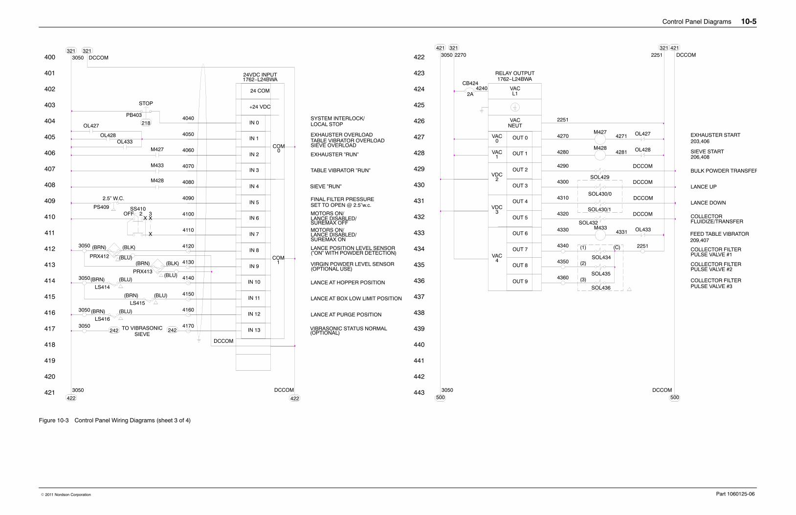
Control Panel Diagrams 10-5
Part 1060125-06� 2011 Nordson Corporation
443
442
441
440
437
438
439
436
435
430
434
433
432
431
429
428
427
426
425
424
422
423
LS415
OFF
421
413
414
415
416
417
418
420
419
412
3050IN 12
STOP
X
4170IN 13
4140
32XX
SS410
4150
4160
IN 11
IN 10
IN 9
IN 8
LOCAL STOPSYSTEM INTERLOCK/
MOTORS ON/
405
404
406
407
408
409
411
410
403
3050
PS409
LS414
2.5” W.C.
M428
OL428
OL427
M427
400
401
402
3050321
4090IN 5
IN 7
IN 6
IN 4
IN 3
4060
4050
4040
IN 2
IN 1
+24 VDC
IN 0
LANCE AT BOX LOW LIMIT POSITION
LANCE AT HOPPER POSITION
SET TO OPEN @ 2.5”w.c.FINAL FILTER PRESSURE
TABLE VIBRATOR OVERLOADEXHAUSTER OVERLOAD
SIEVE ”RUN”
EXHAUSTER ”RUN”
24VDC INPUT1762−L24BWA
24 COM
3050500
OUT 7
OUT 8
OUT 9
VAC
DCCOM500
L1
OUT 0
OUT 1
OUT 2
OUT 4
OUT 3
OUT 5
OUT 6
VDC
VDC
VAC
VAC
NEUTVAC 2251
1762−L24BWARELAY OUTPUT
CB424
3050421 321
2270
4240 VAC
DCCOM321
2251421
4080
DCCOM321
LANCE AT PURGE POSITION
LANCE DISABLED/SUREMAX OFFMOTORS ON/LANCE DISABLED/SUREMAX ON
SOL434
4360
4350
4340
SOL436
SOL435COLLECTOR FILTERPULSE VALVE #3
COLLECTOR FILTERPULSE VALVE #2
2251
OL428
OL427
4290
4300
4280
4270
M428
M427
4281
4271
PULSE VALVE #1COLLECTOR FILTER
203,406
SIEVE START
EXHAUSTER START
COM0
COM1
206,408
TO VIBRASONIC3050242 242 (OPTIONAL)
VIBRASONIC STATUS NORMAL
M433FEED TABLE VIBRATOR209,407
LS416
(BRN) (BLU)
(BLU)(BRN)
(BLU)(BRN)
2A
(3)
(2)
(1) (C)
218
(BLU)
3050 (BRN)
PRX412
(BLK)
DCCOM
4120(”ON” WITH POWDER DETECTION)LANCE POSITION LEVEL SENSOR
OL4334331
4130(BRN)
PRX413
(BLK)
(BLU)(OPTIONAL USE)VIRGIN POWDER LEVEL SENSOR
TABLE VIBRATOR ”RUN”
OL433SIEVE OVERLOAD
4070
4100
4110
DCCOM
422
3050
422
PB403
4320
SOL432
DCCOMFLUIDIZE/TRANSFERCOLLECTOR
4310
SOL430/1
DCCOMLANCE DOWN
SOL430/0
DCCOMLANCE UP
SOL429
DCCOMBULK POWDER TRANSFER
4330
M433
4
3
2
0
1
SIEVE
Figure 10-3 Control Panel Wiring Diagrams (sheet 3 of 4)
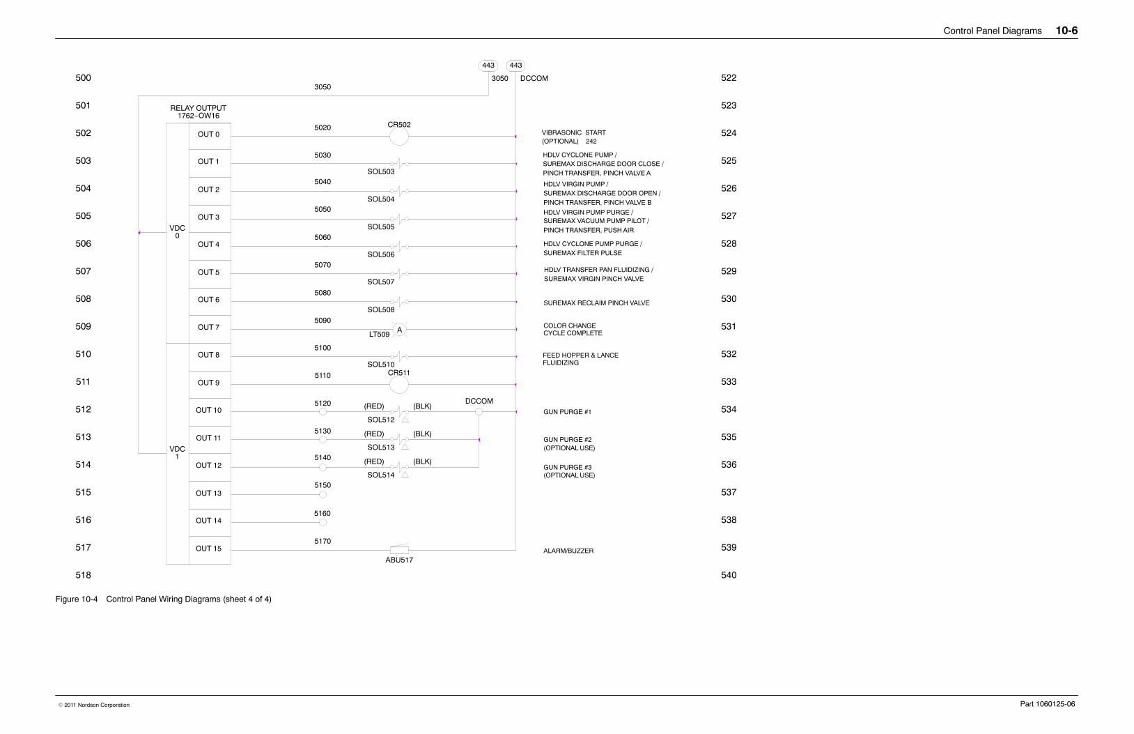
Control Panel Diagrams 10-6
Part 1060125-06� 2011 Nordson Corporation
5140
5150
5130
5120
OUT 14
OUT 15
1VDC
OUT 13
OUT 12
OUT 11
OUT 10
SUREMAX DISCHARGE DOOR CLOSE /
SUREMAX DISCHARGE DOOR OPEN /SOL504
SOL503
5020
5030
5040
5060
5050
5070
5080
5090
5100
5110OUT 9
OUT 8
OUT 6
OUT 7
OUT 5
0VDC
OUT 4
OUT 3
OUT 2
OUT 1
443
3050
1762−OW16RELAY OUTPUT
OUT 0
GUN PURGE #2
GUN PURGE #3
SUREMAX FILTER PULSE
SOL508
SOL506
SOL505
SOL513
SOL514
SOL512
DCCOMGUN PURGE #1512
518
517
516
515
514
513
503
510
511
509
508
507
506
504
505
502
501
500
534
540
539
538
537
536
535
525
532
533
531
530
529
528
526
527
524
523
522DCCOM
443
PINCH TRANSFER, PINCH VALVE A
PINCH TRANSFER, PINCH VALVE B
3050
SOL507
HDLV TRANSFER PAN FLUIDIZING /
5160
ALT509
ABU517
CYCLE COMPLETECOLOR CHANGE
ALARM/BUZZER
VIBRASONIC STARTCR502
(OPTIONAL) 242
SUREMAX RECLAIM PINCH VALVE
SUREMAX VACUUM PUMP PILOT /PINCH TRANSFER, PUSH AIR
5170
CR511
(OPTIONAL USE)
(OPTIONAL USE)
SOL510FEED HOPPER & LANCEFLUIDIZING
(RED) (BLK)
(BLK)(RED)
(BLK)(RED)
HDLV CYCLONE PUMP /
HDLV VIRGIN PUMP /
HDLV VIRGIN PUMP PURGE /
HDLV CYCLONE PUMP PURGE /
SUREMAX VIRGIN PINCH VALVE
Figure 10-4 Control Panel Wiring Diagrams (sheet 4 of 4)

Control Panel Diagrams 10-7
Part 1060125-06� 2011 Nordson Corporation
Pneumatic Diagram
PNEUMATIC LEGEND
VIRGIN PILOT
LANCE FLUIDIZE
COLLECTOR TRANSFER
COLLECTOR FLUIDIZE
FEED HOPPER FLUIDIZE
SUPPLY AIR
ENCLOSUREBOTTOM OF
6mm
10mm
10mm
10mm
10mm
12mm
1”
10mm
SOL505
TOP OF
10mm
10mm
LANCE UP
LANCE DOWN
SOL429
PS409
HI
SOL508
ADJUST TO OPEN
PRESSURECONTACT AT 2.5” H O
2
SOL503 SOL504
6mm FINAL FILTER
10mm
8mm
10mm
6mm
SUREMAX FILTER PULSE / HDLV CYCLONE PUMP PURGE
SUREMAX DISCHARGE CLOSE / HDLV CYCLONE PUMP
SUREMAX DISCHARGE OPEN / HDLV VIRGIN PUMP
10m
m
10mm COLLECTOR FILTERPULSE PRESSURE
3−WAY SGL. SOLENOID, 2 POS.
4−WAY SGL. SOLENOID, 2−POS.PILOT OPERATED
1/4”100 PSI
4
PRESSURE SWITCH (ADJUST.)
SOL430/0SOL51042
30 PSI3/8”
10mm
3/8”30 PSI 10mm
100 PSI 10mm1/4”
2SOL432
4
QUICK DISCONNECT (DISCONNECTED)
PRESSURE GAGE
REGULATOR, W/RELIEF PORT,
SOLENOID VENT*
*EXHAUST PORT OF ALLMANIFOLDS CONNECTEDBY 10mm TUBING TOSOLENOID VENT.
ENCLOSURE VENT
DUAL PRESSURE, BLOCKED CENTER4−WAY DBL. SOLENOID, 3−POS.
SOL430/1
RECLAIM PINCH VALVE
RECLAIM POWDERTRANSFER
6mm
VALVE MANIFOLD ”A” NOTES:PLUG ALL MAINFOLD PORTS 2.PLUG ONE PORT 3 & 5 ON MANIFOLD.VENT ONE PORT 3 & 5 ON MANIFOLD.SUPPLY AIR TO BOTH MANIFOLD PORTS 1.
3/8” 3/8”3/8” 3/8”SUPPLY AIR DISTRIBUTION MANIFOLD
VALVE MANIFOLD ”A”
12mm
VALVE MANIFOLD ”B”13
31
VALVE MANIFOLD ”B” NOTES:PLUG ONE PORT 3 ON MANIFOLD.VENT ONE PORT 3 ON MANIFOLDSUPPLY AIR TO ONE PORT 1 ON MANIFOLD.
3/8” 3/8”
1/4” 1/4”
PORTS 2 AND 4 ARE 1/4NPT
IF NO MANIFOLD ”C”, PLUG ONE PORT 1
SOL507 SOL506
51 5 13 3
3/8”30 PSI 10mm
GA1
RG1
GA2
RG2
GA3
RG3
GA4
RG4
GA5
RG5
NORMALLY CLOSED
6mm
6mm
6mm
6mm
6mm
6mm
VALVE MANIFOLD ”C”1/4”1/4” 31
SUREMAX PUMP PILOT / HDLV VIRGIN PUMP PURGE
VIRGIN PINCH VALVE / HDLV TRANSFER PAN FLUIDIZING6mm
6mm
PORTS 2 AND 4 ARE 1/4 NPT.SUPPLY AIR TO ONE MANIFOLD PORT 1.VENT ONE PORT 3 AND 5 ON MANIFOLD.PLUG ONE PORT 1, 3, AND 5 ON MANIFOLD.
VALVE MANIFOLD ”C” NOTES:
PORT 2 IS 1/8NPT
13 5 13 5 13 5
NOTE:
ENCLOSURE
PLUG ALL MANIFOLD PORTS 2.5
31
5
3/8”
315
12mm
315315
2 4 2 4 22
1 32
1 32
1 32
1 3
2 4
Figure 10-5 Control Panel Pneumatic Diagram