spectrapen - psi.cz€¦ · this operation manual ( on a flash disc) 6. usb flash disc with...
TRANSCRIPT

P
SpectraPenLM500
Instruction Manual
Please read this manual before operating this product
PSI, spol. s r. o., Drásov 470, 664 24 Drásov, Czech RepublicFAX: +420 511 440 901, TEL: +420 511 440 011, www.psi.cz

2
CONTENTS
Contents .................................................................................................................................................................. 2
Instruction Manual .................................................................................................................................................. 3
Technical specifications .......................................................................................................................................... 3
General Description ................................................................................................................................................ 5
Components of the SpectraPen device ................................................................................................................... 7
Description of the SpectraPen device ..................................................................................................................... 8
Care and maintenance ............................................................................................................................................ 9
Operation instructions .......................................................................................................................................... 10
Dark spectrum calibration ............................................................................................................................... 10
Measurement .................................................................................................................................................. 11
Menu descriptions ................................................................................................................................................ 14
Spectrapen software ............................................................................................................................................. 18
Driver Installation ............................................................................................................................................ 18
Software installation ....................................................................................................................................... 20
SpectraPen software menu ............................................................................................................................. 21
Data Transfer and Visualization ....................................................................................................................... 22
Software Update ................................................................................................................................................... 27
GPS Module ........................................................................................................................................................... 28
GPS Module Description and setting ............................................................................................................... 28
GPS / SpectraPen Operation ........................................................................................................................... 29
Data Download ................................................................................................................................................ 29
WARRANTY TERMS AND CONDITIONS .................................................................................................................. 32
Troubleshooting and Customer support ............................................................................................................... 33

3
INSTRUCTION MANUAL
TECHNICAL SPECIFICATIONS
Optical Entrance:
Cosine corrector
FWHM Bandwidth:
7 nm
Spectral Response Range:
UV-VIS: 340 nm - 780nm
NIR: 640 nm – 1,050 nm
Spectral Response Half Width:
9*
Spectral Straylight:
-30dB*
Wavelength Reproducibility:
+/- 0.5 nm
Integration Time:
Automatic, 5 ms to 10 s
Number of pixels:
256
Dimension of Pixel:
0.5 x 15.8 mm
Touch Screen:
240 x 320 pixel; 65,535 colors
Memory Capacity:
16 Mbit (up to 8,000 measurements)
System data:
16 bit A/D conversion
Noise:
15 LSB RMS
Communication:
USB
SpectraPen Software:
4
Windows 7 or higher**
Dimensions:
18 x 7.5 x 4 cm
Weight:
300 g
Case:
Splash-proof
Battery:
Li-ion; rechargeable via USB port of a PC
Battery Life:
48 hours (continuous operation)
Operating Temperature:
0 to 55 ºC
Storage Temperature:
-20 to +60 ºC
Warranty:
1 year parts and labor (see the last page of this Operation Manual for precise warranty conditions)
* When monochromatic light of Λ = 550 nm or Λ = 850 nm is input, spectral stray light is defined as the ratio of the count measured at the input wavelength, to the count measured at a wavelength 40 nm longer or shorter than the input wavelength
** Windows is a registered trademark of Microsoft Corporation.

5
GENERAL DESCRIPTION
SpectraPen LM 500 is a handheld portable spectroradiometer that is ideal as a general-purpose instrument for
research and for agricultural applications. SpectraPen LM 500 measures in radiometric or photometric units the
intensity of the light irradiance and is calibrated for visible light in range of 380 – 780 nm and the light in range
of 640 – 1,050 nm. SpectraPen is used for irradiance measurements, illuminance measurements and CIELAB
chromaticity diagram measurements. SpectraPen is especially useful for rapid measurements of spectral light
quality, for monitoring of artificial lighting and for quantification of light radiation.
The SpectraPen works with Li-Ion rechargeable battery and does not require for operation any PC or any other
bulky accessory. On the SpectraPen touch screen the wavelength and intensity readings and their spectral lines
including correlated color temperature index are instantly displayed. All recorded data are automatically stored
into the device internal memory. The SpectraPen includes a comprehensive software package comprising full
system control, data acquisition and data processing.
The SpectraPen is suited for wide scope of environmental, agricultural and ecological applications such as
monitoring of artificial lighting used in horticulture industry or light source testing.
SpectraPen LM 500 is available in two versions that differ in spectral range:
- LM 500-UVIS: spectral response range 340 to 780 nm
- LM 500-NIR: spectral response range 640 to 1050 nm
SpectraPen LM500 measures the following parameters:
Scope – measures quantitative light intensity at different wavelengths.
- Irradiance spectrum [µW.cm-2
.nm-1
]
- Photon flux density spectrum [µmol.m-2.s
-1.nm
-1]
Light Meter – measures absolute light intensity at defined range of wavelengths of the electromagnetic
spectrum.
- Irradiance [W.m-2
] in user defined range of the electromagnetic spectrum
- Photon flux density [µmol.m-2
.s-1
] in user defined range of the electromagnetic spectrum
- Illuminance [Lux] - total luminous flux incident on a surface, per unit area
- PAR [µmol.m-2
.s-1
]*
Chromaticity Diagram CIE1931 –measure quality of color space and color temperature of the light source.
- CIE color coordinates*
- Correlated color temperature – for LED *
* Valid only for LM 500-UVIS version of SpectraPen LM500

6
Two basic versions of SpectraPen LM 500 are available:
LM-500-H
Cosine corrector facing up
Limited space measurement
Measurements in controlled environment
LM-500-V
Cosine corrector facing front
Field measurement
Tripod mount
7
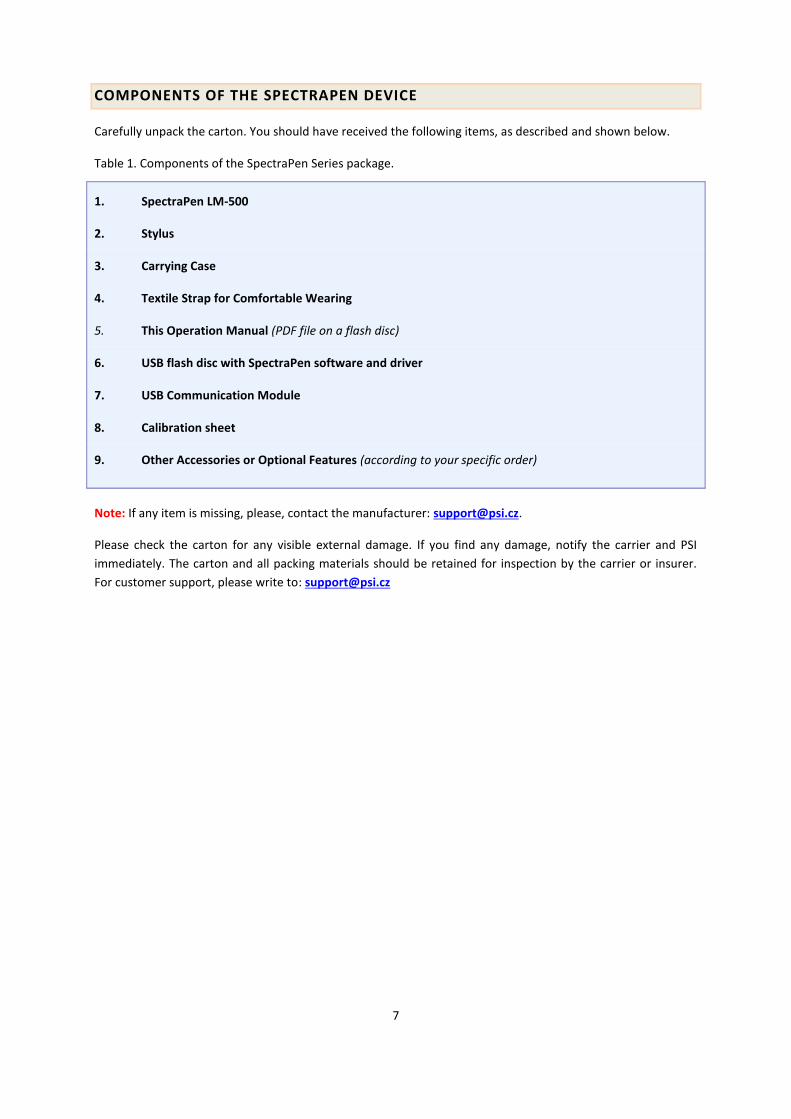
COMPONENTS OF THE SPECTRAPEN DEVICE
Carefully unpack the carton. You should have received the following items, as described and shown below.
Table 1. Components of the SpectraPen Series package.
1. SpectraPen LM-500
2. Stylus
3. Carrying Case
4. Textile Strap for Comfortable Wearing
5. This Operation Manual (PDF file on a flash disc)
6. USB flash disc with SpectraPen software and driver
7. USB Communication Module
8. Calibration sheet
9. Other Accessories or Optional Features (according to your specific order)
Note: If any item is missing, please, contact the manufacturer: [email protected].
Please check the carton for any visible external damage. If you find any damage, notify the carrier and PSI
immediately. The carton and all packing materials should be retained for inspection by the carrier or insurer.
For customer support, please write to: [email protected]

8
DESCRIPTION OF THE SPECTRAPEN DEVICE
SpectraPen is compact, durable and lightweight device operated by single Turn ON/OFF button and touch
screen. It integrates radiometric calibration for analysis of spectral response in range from 380-1050 nm.
SpectraPen device is optimized for photobiological applications and easy rapid measurements inside of the
controlled environment as well as outside in the field. SpectraPen consists of cosine corrected head, main body
with color LCD display with touch screen, USB connector and main power button. SpectraPen is calibrated and
the calibration sheets are provided.
SpectraPen is programmable via intuitive touch-screen. For data collection and analysis comprehensive
software package is provided. Via USB connector SpectraPen LM 500 can be connected to PC for further data
collection and analysis.

9
COSINE CORRECTOR – LIGHT SENSOR
The optical part of the SpectraPen, cosine corrector, is placed inside of the black box front panel which protects
the optics from dirt or moisture. The sensor part made of teflon is placed either on top or in front of the optical
head depending on the device version.
Each SpectraPen device is calibrated with the certified light source AvaLight- DH-BAL-CAL. Calibration
certificate is provided by the manufacturer for each device. It is recommended to re-calibrate the device after
24 months by the manufacturer.
Integration time of the internal detector is set automatically according to the ambient light intensity up to
maximum integration time of ten seconds.
Important note: The sensor part should be always dust and dirt free and maintained carefully as any scratches
on the surface might interfere with the correct results of the measurement.
COLOUR LCD DISPLAY
The SpectraPen is operated via touch screen by using provided stylus. Software operated instructions are
provided on page 18.
Please note: No sharp objects should be used for operating the SpectraPen via touch screen. It is
recommended to use provided stylus for the software operation.
USB CONNECTOR
USB connector is used for operation of the SpectraPen device directly from PC via the SpectraPen software and
for re-charging the device batteries. Please note that SpectraPen device is automatically re-charged when
connected to the PC via the USB connector.
POWER BUTTON
Power button is the main Switch ON/OFF button.
CARE AND MAINTENANCE
Never submerge the device in water!
The device should not come in contact with any organic solvents, strong acids or bases.
Battery life is approximately 48 hours when the SpectraPen is operated continuously.
It is recommended to re-calibrate the device by the manufacturer after 24 months upon purchase.
10
OPERATION INSTRUCTIONS
In the next chapter initial set-up operation of the SpectraPen device is presented and the step-by-step
description of the measurement procedure is shown.
Switch ON the device with POWER BUTTON and follow next steps to perform the measurements. In case the device battery is not charged connect the SpectraPen with USB cable via USB port to the PC and charge the batteries.
Before any parameters are measured with SpectraPen device dark spectrum scan MUST be performed. Dark spectrum scan must performed always after the device is switched ON or periodically upon given period of time when the device is operating. A dark spectrum scan is the equivalent of zeroing the instrument and the user should perform a dark scan each time changes are made in the Setup menu. Please follow next steps to perform Dark Spectrum Calibration step.
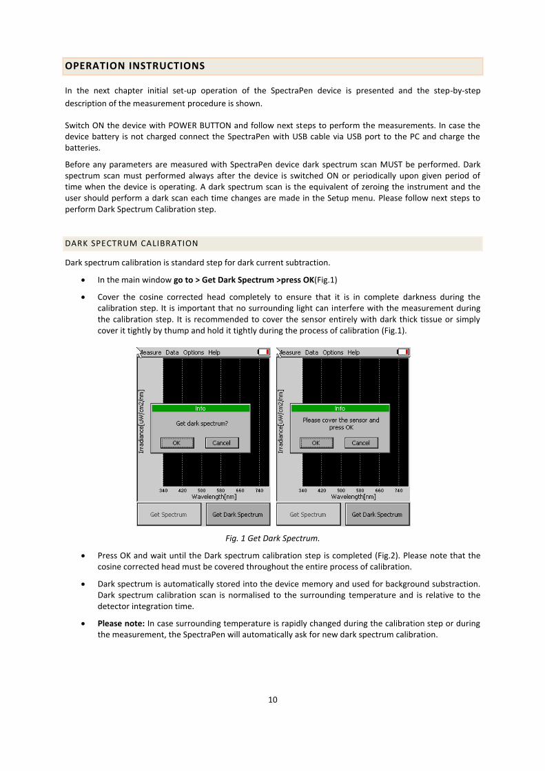
DARK SPECTRUM CALIBRATION
Dark spectrum calibration is standard step for dark current subtraction.
In the main window go to > Get Dark Spectrum >press OK(Fig.1)
Cover the cosine corrected head completely to ensure that it is in complete darkness during the calibration step. It is important that no surrounding light can interfere with the measurement during the calibration step. It is recommended to cover the sensor entirely with dark thick tissue or simply cover it tightly by thump and hold it tightly during the process of calibration (Fig.1).
Fig. 1 Get Dark Spectrum.
Press OK and wait until the Dark spectrum calibration step is completed (Fig.2). Please note that the cosine corrected head must be covered throughout the entire process of calibration.
Dark spectrum is automatically stored into the device memory and used for background substraction. Dark spectrum calibration scan is normalised to the surrounding temperature and is relative to the detector integration time.
Please note: In case surrounding temperature is rapidly changed during the calibration step or during the measurement, the SpectraPen will automatically ask for new dark spectrum calibration.

11
Fig. 2 Get Dark Spectrum.
MEASUREMENT
SpectraPen can measure number of parametres that are derived from measurement of:
- light intensity at different wavelengths (Scope)
- - measurements of absolute light intensity at defined range of wavelengths of the electromagnetic
spectrum (Light meter)
- - measurements of quality of color space and color temperature of the light source (Chromaticity
diagram).
Irradiance measurements display units in Moles per square meter per second and nm or per Watts and square
meter. Illuminance measures of how much the incident light illuminates the surface, wavelength-weighted by
the luminosity function to correlate with human brightness perception. Iluminance measurements are
displayed in units of Lux. Chromaticity diagram measures color of light and correlated color temperature (CCT).
Color of light is displayed using the xy chromaticity diagram and the related dominant wavelength. CCT is the
color temperature of a black-body radiator which to human color perception most closely matches the light
from the light source.
Please note that for proper lights spectra measurement, the SpectraPen device should be perpendicular to the
light source for LM500-H and parallel with the light source for LM500-V version.
To perform the individual measurements please follow the next steps.
In the main window go to Measure >Select the desired function (Fig.3)
Scope
Light meter
Chromaticity diagram

12
Fig. 3 Selection of type of measurement.
SCOPE
Scope function is used for measurement of light intensity at different wavelengths (Fig. 4). Irradiance measurements display units as photon flux density in moles per square meter per second and nm (µmol/m
2/s)
or as irradiance per Watts and square centimetre and nm (µW/cm2/nm).
To perform the measurement Go to > Measure > Scope> Get Spectrum
The spectra of the light source will be acquired, stored to the device memory and displayed on the screen.
To change the units displayed please go to Options>Settings.
Fig. 4Measurement of Scope
LIGHT METER
Light meter function is used for measurements of absolute light intensity at defined range of wavelengths (Fig.5). Photon flux density measurements display units in Moles per square meter per second, irradiance measurements per Watts and square meter and illuminance measurements are displayed in units of Lux.
To perform the measurement Go to >Measure > Light Meter>Get Spectrum

13
Light intensity of the light source will be acquired, stored to the device memory and displayed on the screen. Light intensity is measured and expressed in W/m
2, µmol/m
2/s and LUX for illuminance.
Fig. 5 Light meter window.
Please note that the Light Meter integrates the value based on the wavelength range defined. For UV-VIS LM500 this is in range 340-780 nm. The user can define the wavelength range to be measured and use this tool to measure specific spectral regions of interest by going to Options>Settings and setting the required range. To measure photosynthetically active radiation (PAR) change the settings and set the values from 400 to 700 nm.
CHROMATICITY DIAGRAM
Chromaticity diagram function is used for measurement of light color and correlated color temperature (CCT) using the International Commission on Illumination (CIE) techniques (Fig. 6). Chromaticity diagram function uses standard coordinates of the 1931 CIE colorimetric system by which all possible colours can be uniquely identified.A color space is a uniform representation of visible light. It maps all of the colors visible to the human eye onto an x-y grid and assigns them measureable values. This allows us to make uniform measurements and comparisons between colors.
To perform the measurement Go to > Measure >Chromaticity diagram> Get Spectrum
The colour of the light source in the CIE1931 colorimetric system is marked by black cross. The x- and y- coordinates of the measured light source will be determined and the CCT value will be calculated and displayed on the screen.
Please note that the CCT values are not automatically stored.

14
Fig. 6 Chromaticity diagram function
MENU DESCRIPTIONS
In the next chapter set-up menu is described.
DATA
Browse– displays data browse dialog box. The user can browse the list of stored data, select the set of data files and view the light spectra in SCOPE mode. Colour classification of each data file helps the user to discriminate between individual measurements.
PAR bookmark allows the user to view the light intensity in PAR spectral region for the acquired data. PAR is photosynthetically active radiation integrated in range 400-700nm.
Erase – erase function is used to erase internal data memory
Memory info – displays info on amount of used internal memory of the SpectraPen LM500 device
Fig. 7 Browse function

15
OPTIONS
Settings– function is used to set various variable for the light measurements and for the device settings
Graph – displays options for setting the wavelength range and graph features (Fig. 8)
Zoom enable – enables the zoom feature. With the stylus select an area (in the right-down direction) of the displayed graph which you want to zoom in. Reverse these steps if you want to return to the original display.
Marker enable – enables to display exact numeric value for the point selected in the Scope graph window. Exact wavelength and light irradiance are displayed for the point touched on the graphical display. In top right corner of the LCD display is shown exact value of wavelength in nm for the user selected position in spectra in the scope display. In addition light irradiance for the given nm is shown.
Smoothing – enables noise reduction of the graphical display by Smoothing the noise in the spectrum at the expense of spectral resolution.
Wavelength range – defines the range of wavelengths considered for light scope and light meter measurements. Desired wavelength range can be adjusted by selecting the wavelength and by using the arrows up and down.
Fig. 8 Graph settings.
Time - displays actual time and date (all data files are stored by time and date signature). To change time and/or date specifications touch on one of the values and adjust it via arrows.

16
Fig. 9 Time settings
Miscellaneous – is used to adjust LCD display control settings
Backlight intensity – move slider to adjust back light intensity
Backlight time-out – move slider to adjust backlight time-out (time of inactivity required before backlight will dim out to save battery life).
Fig. 9 Miscellaneous settings
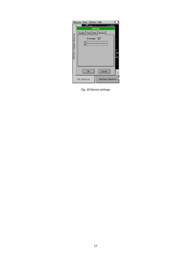
Device
Average –Average function is used for adjusting the number of scans for each reading. Averaging of more scans results in a higher signal-to-noise ratio but increases the time required for each reading that appears on the screen. Move slider to set the number of measurement to be acquired for averaged values.
17
Fig. 10 Device settings

18
SPECTRAPEN SOFTWARE
SpectraPen software is used for visualisation and data transfer from SpectraPen device to the PC. Please follow
next steps to install the SpectraPen drivers and SpectraPen software. Please note that SpectraPen software and
driver are stored on the USB flash disc provided together with the device by the manufacturer.
DRIVER INSTALLATION
1. Connect the USB flash disc to your computer. Press Start of your PC and Select Control Panels
2. Navigate through System and Security and go to Device Manager
3. Connect the SpectraPen device to the PC via the USB connector. In the list of Other Devices, as seen in
Device Manager, PSI USB Device should appear. Right click on the PSI USB Device and select Update
Driver Software.

19
4. Go to Browse my computer for driver software and select Driver folder on the SpectraPen installation
USB flash disk. Install the driver.
5. Installation of the driver is now complete.

20
SOFTWARE INSTALLATION
1. Save the SpectraPen software provided on the USB flash disk to your computer and launch the
SpectraPen program.
2. To connect and recognise your SpectraPen device in the SpectraPen software proceed first with the
registration of your SpectraPen software (Fig.11).
Go to Help>Registration.
Enter your serial (registration) number. Please note that you will find your serial (registration) number
in the file SN.txt, which is included on the enclosed USB flash disk.
Select: Register.
Fig. 11 Registration step
3. Connect SpectraPen device by going to Device ->Connect
4. When the device is connected properly message “SpectraPen” appears in the bottom left part of the
screen (please note the red circle in the picture below) and a small USB icon will appear in the top
right corner of the SpectraPen device display.
Fig. 12 Online operation of SpectraPen device
5. In case SpectraPen device is not recognised message Device: Not connected will occur in the bottom
left corner.

21
SPECTRAPEN SOFTWARE MENU
Menu: File
Load Loads previously saved data files.
Save Saves data to hard disc.
Export Exports data in .txt format.
Export JSON Exports data in JavaScript Object Notation.
Close Closes the current experiment.
Close All Closes all running experiments.
Exit Exits the program.
Menu: Device
Connect Detects and connects the device.
Update Firmware Used for firmware updates.*
Attach GPS File Used for download data from GPS module.
Memory Erase Erases data from the SpectraPen memory.
* For more information on software updating, see page 29 of this Operation Manual.
Menu: Setup
Update Software Used for software updates.
Settings On/off - Auto Memory Erase After
Download.
Menu: Help
Registration Used for the SpectraPen software
registration.
About Offers basic information about the
program.

22
DATA TRANSFER AND VISUALIZATION
To download, visualise and further process the measured data please follow the next instructions.
1. Perform the measurement and connect the SpectraPen device to the computer.
2. Launch the SpectraPen software and Connect the device. Go to Device> Connect.
3. To visualise the stored data use the Download function to transfer your data from the SpectraPen
device to your PC. Select icon on left side of screen or go to File and select Load if you want to process
data stored on PC.
4. All data stored currently in the SpectraPen device will be shown in the main window view. All data
stored are logged with time when measurement, experiment respectively, was performed. By default
Scope curves are shown as the first pop-up window (Fig. 13). To view irradiance data go to Irradiance
bookmark (Fig. 14).
Please note that if there are no data stored in the memory, the download function is not functional.
Fig. 13 Scope spectra
5. All data that are downloaded are displayed in the Scope window after download from the SpectraPen
LM500 device. The user can select the set of measurements to be displayed by marking and
unmarking the data from the selection list (see Selection of data in the right side of the Fig. 13).
6. In the graph marker feature is available, which enables display of the numeric values for wavelength and light irradiance for the selected wavelength of the scan (Fig. 14). Use the mouse to select the given point. In top right corner of the graph (red circle) is displayed exact value for the selected point in nm (x-axis) and values on y-axis.
7. To zoom in the graph select an area (in the right-down direction) of the displayed graph which you want to zoom in (Fig. 15). If you want to reverse these steps and return to original display use minus icon in the corners of the zoom area as depicted by red arrows in Fig. 15.

23
Fig. 14 Irradiance spectra
Fig. 14 Marker feature

24
Fig. 15 Zoom feature
8. Go to Irradiance bookmark to view the irradiance data stored either as moles per square meter per
second and nm or per Watts and square meter. To change the units in which the spectra is displayed
click on the unit icon as depicted by blue arrow in Fig. 16. The irradiance data will be displayed with
the selected units (Fig.17).
9. To view the light meter data for the spectral scans acquired click on the unit icon as depicted by red
arrow in Fig. 16. Irradiance and illuminance light meter values for each scan are displayed as LUX and
PAR values (Fig.18).
Fig. 16 Irradiance spectra in units of µmol/m2/s/nm

25
Fig. 17 Irradiance spectra in units of µW/cm/nm.
Fig. 18 Light meter numeric values
10. To Save the experiment Go to>File>Save. All data stored in the device memory will be saved
irrespective of the file selection in the online window. The file will be stored as .spec. Spec files stores
all Scope and Light meter data.
11. Acquired scan data and numeric data can be exported for further processing. Go to> File>Export to
export the data in .txt format. Export function allows the user to specify the type of data that should
be exported as shown in Fig. 19. The options are:
Spectrum – all raw scope data for entire range of measured wavelengths are exported including data
for the dark scan.
Spectrum scope – scope data normalised to dark spectrum scan are exported for all acquired scans or
set of selected measurements

26
Spectrum Irradiance – irradiance data for all measurements are exported. The user can choose to
export the numeric values either in µmol/m2/s/nm, µW/cm
2/nm or both.
Computed Data – computed numeric values for Scope and Irradiance are exported for all
measurements. The user can choose if only Scope numeric values or Irradiance numeric values are
exported. For irradiance values, numeric data for PAR in µmol/m2/s units, irradiance in µW/cm
2 units
and illuminance in LUX units are exported.
Fig. 19 Data export
Fig. 20 Edit the measure name
12. The user can rename the data in the SpectraPen software. Go to selected measurement in the selection column on the right side of the window and use the right click of the mouse to open the window for editing the names of the measurements and the selection (Fig. 20).

27
SOFTWARE UPDATE
Very important!
The SpectraPen memory is erased during the software update!
Before starting any software update, export all your data from the SpectraPen memory into your computer!
Starting Update
1. Starting Update
Select: Setup>Update Firmware
2. Selecting .bxn File
Find: Binary file (with the extension .bxn)
Select: Open
Finishing Upload
Select:“OK” to start uploading of the update.
Upload progress is indicated in the status bar.
Press: “OK” to finish upload.

28
GPS MODULE
Please follow next steps if your device is purchased together with the GPS module.
IMPORTANT INFORMATION:
For proper GPS reading, the TIME in your SpectraPen and in your computer must be synchronized! Preset
time and time zone must correspond to GPS time (time zone) in your location.
GPS MODULE DESCRIPTION AND SETTING
Step 1: AA Batteries Installation
The device operates on two AA batteries. You can use alkaline, NiMH or lithium batteries. Use NiMH of lithium
batteries for best results.
1. Turn the D-ring counter clockwise and pull up to remove the cover.
29
2. Insert the batteries, observing polarity.
3. Replace the battery cover and turn the D-ring clockwise.
4. Hold
5. Select Setup->System->Battery Type
6. Select Alkaline, Lithium or Rechargeable NiMH
Step 2: GPS Device setting
1. Hold
2. After the device is on, it begins acquiring satellite signals. The device may need a clear view of the sky
to acquire satellite signals.
3. You can check current position and accuracy in Satellite Page
4. For better precision you can enable GPS+GLONASS mode in Setup->System
5. ->Satellite System->GPS+GLONASS and turn WAAS/EGNOS On.
6. Make sure that USB Mode is set to Mass Storage (Setup->System->USB Mode)
7. For more information please check Garmin eTrex manual.
GPS / SPECTRAPEN OPERATION
Step 1: Time Synchronization
Synchronize the SpectraPen time with the time of your PC. Time must be set correctly witch respect to your
time zone.
Step 2: GPS Positioning
Switch the GPS module on and wait until the GPS position is fixed (GPS green LED indicator flashes 1s ON and
2s OFF while tracking the position).
Step 3: Operation
Be aware that while performing experiments, the SpectraPen and the GPS module must be kept close to each
other.
DATA DOWNLOAD
Step 1: Enabling Communication
Switch on the computer, SpectraPen, and GPS module and set your computer to SpectraPen communication.
Step 2: Downloading SpectraPen Data
Start: SpectraPen program.
Connect: SpectraPen device.
Download: Measured data from the SpectraPen to your PC.

30
Step 3: Connecting GPS Module
Connect the GPS Module to your PC. Communication is set properly if the hardware is recognized by your PC.
Step 4: Downloading GPS Data
Select: Device>Attach GPS file to download data from the GPS module.
Step 5: Completing the Download
Successfully downloaded GPS coordinates paired with SpectraPen data.

31

32
WARRANTY TERMS AND CONDITIONS
This Limited Warranty applies only to the SpectraPen series devices. It is valid for one year from the date of shipment.
If at any time within this warranty period the instrument does not function as warranted, return it and the manufacturer will repair or replace it at no charge. The customer is responsible for shipping and insurance charges (for the full product value) to PSI. The manufacturer is responsible for shipping and insurance on return of the instrument to the customer.
No warranty will apply to any instrument that has been (i) modified, altered, or repaired by persons unauthorized by the manufacturer; (ii) subjected to misuse, negligence, or accident; (iii) connected, installed, adjusted, or used otherwise than in accordance with the instructions supplied by the manufacturer.
The warranty is return-to-base only, and does not include on-site repair charges such as labor, travel, or other expenses associated with the repair or installation of replacement parts at the customer's site.
The manufacturer repairs or replaces faulty instruments as quickly as possible; the maximum time is one month.
The manufacturer will keep spare parts or their adequate substitutes for a period of at least five years.
Returned instruments must be packaged sufficiently so as not to assume any transit damage. If damage is caused due to insufficient packaging, the instrument will be treated as an out-of-warranty repair and charged as such.
PSI also offers out-of-warranty repairs. These are usually returned to the customer on a cash-on-delivery basis.
WEAR & TEAR ITEMS (such as sealing, tubing, padding, etc.) are excluded from this warranty. The term WEAR & TEAR denotes the damage that naturally and inevitably occurs as a result of normal use or aging even when an item is used competently and with care and proper maintenance.
33
TROUBLESHOOTING AND CUSTOMER SUPPORT
In case of troubles and for customer support, please, write to [email protected] contact your local distributor.
Manual Version: 2015/04
© PSI (Photon Systems Instruments), spol. s r.o.