specken drumag
TRANSCRIPT

ìëó×
Cyl
ind
ers
Compact cylinders STRONG series Ø 32 ÷ 63 mm
A new series of compact cylinders for long strokes and heavy-duty applications standard supplied with oversizedguides and rods, the first one with adjustable pneumatic cushioning without variations in size. The inter-axes,centering diameters and rods are in accordance with ISO 6431 and VDMA 24562 specifications.
Working pressure: 1,5 ÷ 10 barAmbient temperature: -20°C ÷ 80°CFluid: filtered air, lubricated or notBarrel profile of extruded aluminium alloywith chromium-plated piston rod.Oversized guides.Adjustable cushioning (10 mm ~).The version with non-rotating piston rod(RQ-�series) is standard supplied with assembled flange.Max. operating speed: 1 m/s.Magnetic version.
TECHNICAL CHARACTERISTICS
Codification Key
Type
Bore (mm)
Standard stroke (mm)
Series
0025RS 201 032 -
Option
SERIES
Compact cylinders STRONG Ø 032 ÷ 063 mm, magneticversion, with cushioning and oversized guides standardsupplied:Round barrel:RS series - compact STRONGOctagonal barrelRQ series - compact STRONG non-rotating piston rod with flange. TYPERS series1-- with stainless steel piston rod2-- with chromium-plated steel piston rod-00 D.A.-01 D.A. through piston rod-10 D.A. non-rotating piston rod-11 D.A. non-rotating through piston rod-20 D.A. long piston-60 S.A. retracted piston rod-70 S.A. extended piston rod3-- with male piston rod in stainless steel4-- with male piston rod in chromium-plated steel-00 D.A.-01 D.A. through piston rod-20 D.A. long piston-60 S.A. retracted piston rod-70 S.A. extended piston rod
RQ series1-- with piston rod in stainless steel2-- with piston rod in chromium-plated steel-00 D.A.-01 D.A. through piston rod-20 D.A. long piston-60 S.A. rectracted piston rod-70 S.A. extended piston rod
BORE
032 - 040 - 050 - 063 mm
STANDARD STROKE
Single acting0005-0010-0015-0020-0025 mmMax. stroke: 0025 mm
Double acting0005-0010-0015-0020-0025-0030-0040-0050-00600080-0100-0125-0150-0160-0175-0200-0250-03000320-0350-0400-0450-0500-0600-0700-0800 mmMax stroke: Ø 32-40 0400 mm
Ø 50 0500 mmØ 63 0800 mm
Version with extended pistonMax stroke: Ø 32-40 0800 mm
Ø 50-63 1000 mm
OPTION
C = with flange for RS series versions 100/101/160/170and 200/201/260/270
H = hollow piston rod only for versions with throughpiston rod
G = prearranged for locking unit with the exception ofsingle-acting cylinders and only with piston rod inchromium-plated steel.
Upon request- Magnetic sensor DF-� (Section accessories page 2)- Wire protection strap for magnetic sensor part no.DHF-002100.- Flange for RS series types 200-201-260-270.- Hollow piston rod only for through piston rod version.- Suitable for locking unit only with chromium-plated rod.- Slide units only for cylinder types with extended piston.
(Vedi pag. 63-×)
ìêó×
Cyl
ind
ers
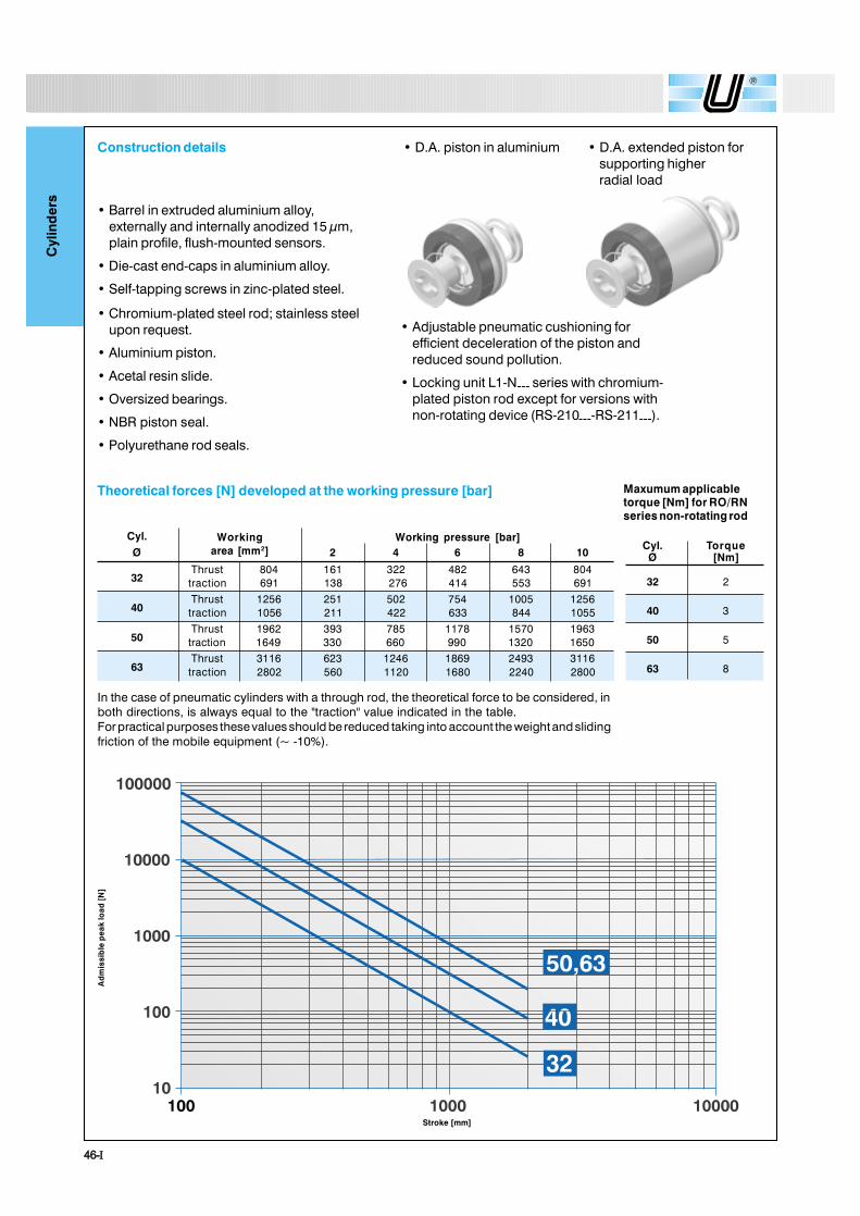
� Barrel in extruded aluminium alloy,externally and internally anodized 15 µm,plain profile, flush-mounted sensors.
� Die-cast end-caps in aluminium alloy.
� Self-tapping screws in zinc-plated steel.
� Chromium-plated steel rod; stainless steelupon request.
� Aluminium piston.
� Acetal resin slide.
� Oversized bearings.
� NBR piston seal.
� Polyurethane rod seals.
� Adjustable pneumatic cushioning forefficient deceleration of the piston andreduced sound pollution.
� Locking unit L1-N--- series with chromium-plated piston rod except for versions withnon-rotating device (RS-210----RS-211---).
Construction details
Stroke [mm]
Ad
mis
sib
le p
eak
load
[N
]
� D.A. extended piston forsupporting higherradial load
In the case of pneumatic cylinders with a through rod, the theoretical force to be considered, inboth directions, is always equal to the "traction" value indicated in the table.For practical purposes these values should be reduced taking into account the weight and slidingfriction of the mobile equipment (~ -10%).
Cyl.Ø 2 4 6 8 10
32Thrust 804 161 322 482 643 804
traction 691 138 276 414 553 691
40Thrust 1256 251 502 754 1005 1256
traction 1056 211 422 633 844 1055
50Thrust 1962 393 785 1178 1570 1963
traction 1649 330 660 990 1320 1650
63Thrust 3116 623 1246 1869 2493 3116
traction 2802 560 1120 1680 2240 2800
Working pressure [bar]Workingarea [mm2]
Theoretical forces [N] developed at the working pressure [bar]
Cyl. TorqueØ [Nm]
32 2
40 3
50 5
63 8
Maxumum applicabletorque [Nm] for RO/RNseries non-rotating rod
� D.A. piston in aluminium
ìéó×
Cyl
ind
ers
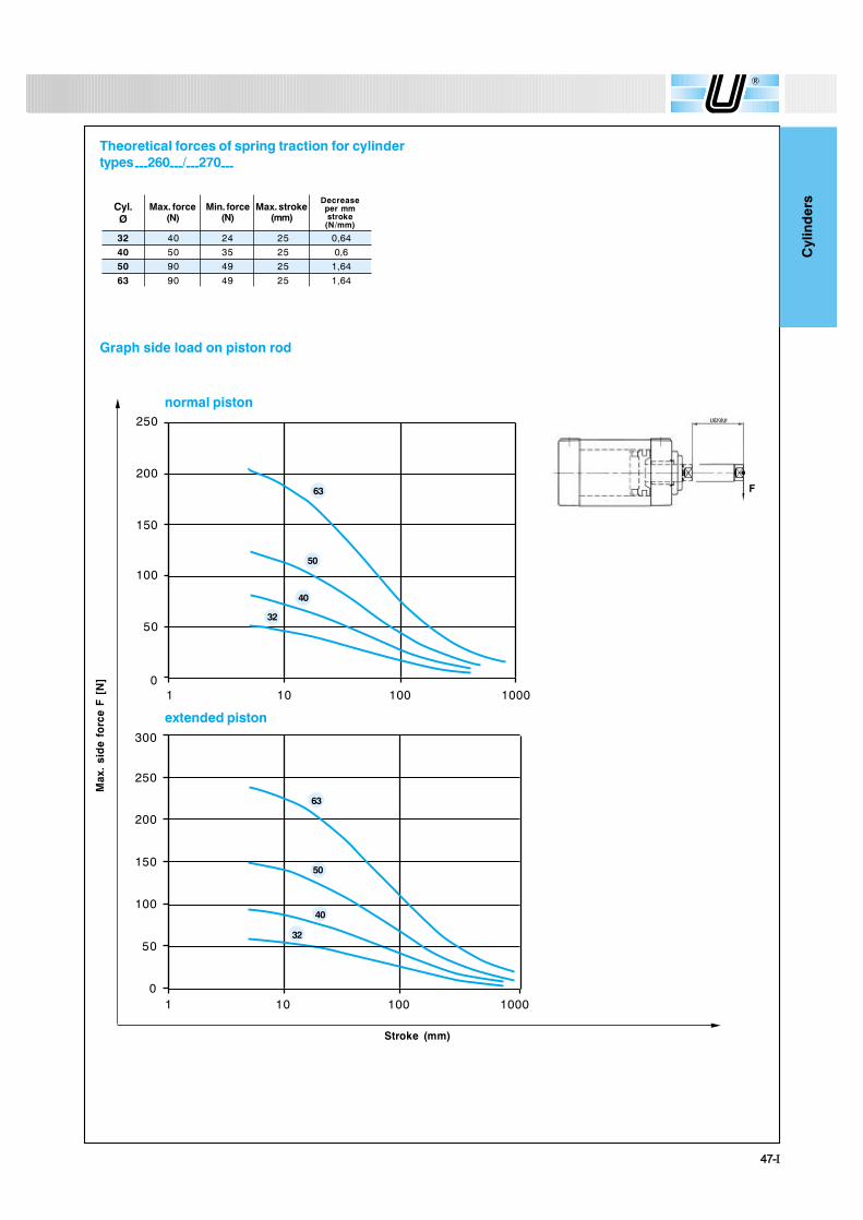
Graph side load on piston rod
Max
. si
de
forc
e F
[N
]
Stroke (mm)
extended piston
normal piston250
200
150
100
50
01 10 100 1000
300
250
200
150
100
50
01 10 100 1000
50
40
32
63
50
40
32
Theoretical forces of spring traction for cylindertypes---260---/---270---
32 40 24 25 0,6440 50 35 25 0,650 90 49 25 1,6463 90 49 25 1,64
Cyl.Ø
Max. force(N)
Min. force(N)
Max. stroke(mm)
Decreaseper mmstroke
(N/mm)
63
stroke
F
ìèó×
Cyl
ind
ers
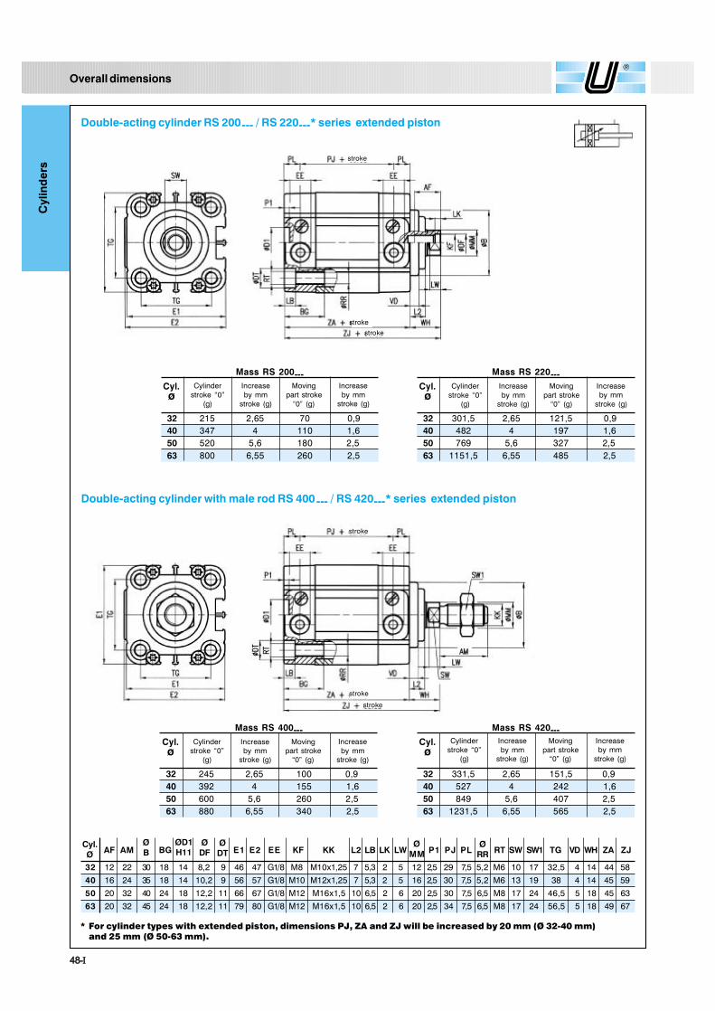
Overall dimensions
Double-acting cylinder RS 200--- / RS 220---* series extended piston
Double-acting cylinder with male rod RS 400--- / RS 420---* series extended piston
Mass RS 220---
32 301,5 2,65 121,5 0,940 482 4 197 1,650 769 5,6 327 2,563 1151,5 6,55 485 2,5
Cyl.ø
Mass RS 420---
32 331,5 2,65 151,5 0,940 527 4 242 1,650 849 5,6 407 2,563 1231,5 6,55 565 2,5
Cyl.ø
* For cylinder types with extended piston, dimensions PJ, ZA and ZJ will be increased by 20 mm (Ø 32-40 mm)and 25 mm (Ø 50-63 mm).
Mass RS 200---
32 215 2,65 70 0,940 347 4 110 1,650 520 5,6 180 2,563 800 6,55 260 2,5
Cyl.ø
Mass RS 400---
32 245 2,65 100 0,940 392 4 155 1,650 600 5,6 260 2,563 880 6,55 340 2,5
Cyl.ø
stroke
stroke
stroke
stroke
stroke
stroke
Cylinderstroke �0�
(g)
Increaseby mm
stroke (g)
Movingpart stroke
�0� (g)
Increaseby mm
stroke (g)
Cylinderstroke �0�
(g)
Increaseby mm
stroke (g)
Movingpart stroke
�0� (g)
Increaseby mm
stroke (g)
Cylinderstroke �0�
(g)
Increaseby mm
stroke (g)
Movingpart stroke
�0� (g)
Increaseby mm
stroke (g)
Cylinderstroke �0�
(g)
Increaseby mm
stroke (g)
Movingpart stroke
�0� (g)
Increaseby mm
stroke (g)
AF AM BG E1 E2 EE KF KK L2 LB LK LW P1 PJ PL RT SW SW1 TG VD WH ZA ZJ
32 12 22 30 18 14 8,2 9 46 47 G1/8 M8 M10x1,25 7 5,3 2 5 12 2,5 29 7,5 5,2 M6 10 17 32,5 4 14 44 58
40 16 24 35 18 14 10,2 9 56 57 G1/8 M10 M12x1,25 7 5,3 2 5 16 2,5 30 7,5 5,2 M6 13 19 38 4 14 45 59
50 20 32 40 24 18 12,2 11 66 67 G1/8 M12 M16x1,5 10 6,5 2 6 20 2,5 30 7,5 6,5 M8 17 24 46,5 5 18 45 63
63 20 32 45 24 18 12,2 11 79 80 G1/8 M12 M16x1,5 10 6,5 2 6 20 2,5 34 7,5 6,5 M8 17 24 56,5 5 18 49 67
ØD1H11
ØDF
ØRR
ØDT
ØMM
Cyl.Ø
ØB

ìçó×
Cyl
ind
ers
Double-acting cylinder, through piston rod RS 201 --- series
Double-acting cylinder, through male piston rod RS 401 --- series
AF AM BG E1 E2 EE KF KK L2 LB LK LW PJ PL RT SW SW1 TG VD WH ZA ZM
32 12 22 30 18 8,2 9 46 47 G1/8 M8 M10x1,25 7 5,3 2 5 12 29 7,5 5,2 M6 10 17 32,5 4 14 44 72
40 16 24 35 18 10,2 9 56 57 G1/8 M10 M12x1,25 7 5,3 2 5 16 30 7,5 5,2 M6 13 19 38 4 14 45 73
50 20 32 40 24 12,2 11 66 67 G1/8 M12 M16x1,5 10 6,5 2 6 20 30 7,5 6,5 M8 17 24 46,5 5 18 45 81
63 20 32 45 24 12,2 11 79 80 G1/8 M12 M16x1,5 10 6,5 2 6 20 34 7,5 6,5 M8 17 24 56,5 5 18 49 85
ØDF
ØRR
ØDT
ØMM
Cyl.Ø
ØB
Mass
32 245 3,55 96 1,840 392 5,6 151 3,250 596 8,1 250 563 875 9,05 330 5
Cyl.ø
Mass
32 305 3,55 156 1,840 482 5,6 241 3,250 756 8,1 410 563 1035 9,05 490 5
Cyl.ø
stroke
stroke stroke
stroke
stroke
stroke stroke
stroke
Cylinderstroke �0�
(g)
Increaseby mm
stroke (g)
Movingpart stroke
�0� (g)
Increaseby mm
stroke (g)
Cylinderstroke �0�
(g)
Increaseby mm
stroke (g)
Movingpart stroke
�0� (g)
Increaseby mm
stroke (g)
ëðó×
Cyl
ind
ers
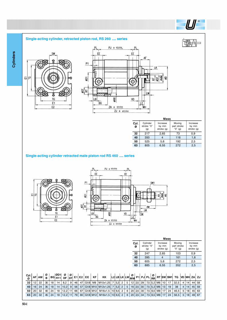
Single-acting cylinder, retracted piston rod, RS 260 --- series
Single-acting cylinder retracted male piston rod RS 460 --- series
Mass
32 217 2,65 73 0,940 350 4 116 1,650 525 5,6 192 2,563 805 6,55 272 2,5
Cyl.ø
Mass
32 247 2,65 103 0,940 395 4 161 1,650 605 5,6 272 2,563 885 6,55 352 2,5
Cyl.ø
stroke
stroke
stroke
Cylinderstroke �0�
(g)
Increaseby mm
stroke (g)
Movingpart stroke
�0� (g)
Increaseby mm
stroke (g)
Cylinderstroke �0�
(g)
Increaseby mm
stroke (g)
Movingpart stroke
�0� (g)
Increaseby mm
stroke (g)
stroke
stroke
stroke
AF AM BG E1 E2 EE KF KK L2 LB LK LW P1 PJ PL RT SW SW1 TG VD WH ZA ZJ
32 12 22 30 18 14 8,2 9 46 47 G1/8 M8 M10x1,25 7 5,3 2 5 12 2,5 29 7,5 5,2 M6 10 17 32,5 4 14 44 58
40 16 24 35 18 14 10,2 9 56 57 G1/8 M10 M12x1,25 7 5,3 2 5 16 2,5 30 7,5 5,2 M6 13 19 38 4 14 45 59
50 20 32 40 24 18 12,2 11 66 67 G1/8 M12 M16x1,5 10 6,5 2 6 20 2,5 30 7,5 6,5 M8 17 24 46,5 5 18 45 63
63 20 32 45 24 18 12,2 11 79 80 G1/8 M12 M16x1,5 10 6,5 2 6 20 2,5 34 7,5 6,5 M8 17 24 56,5 5 18 49 67
ØD1H11
ØDF
ØRR
ØDT
ØMM
Cyl.Ø
ØB

ëïó×
Cyl
ind
ers
Single -acting cylinder extended piston rod RS 270 --- series
Single-acting cylinder, extended male piston rod RS 470 --- series
Mass
32 213 2,65 73 0,940 344 4 116 1,650 515 5,6 192 2,563 795 6,55 272 2,5
Cyl.ø
Mass
32 243 2,65 103 0,940 398 4 161 1,650 595 5,6 272 2,563 875 6,55 352 2,5
Cyl.ø
stroke
stroke stroke
stroke
stroke
Cylinderstroke �0�
(g)
Increaseby mm
stroke (g)
Movingpart stroke
�0� (g)
Increaseby mm
stroke (g)
Cylinderstroke �0�
(g)
Increaseby mm
stroke (g)
Movingpart stroke
�0� (g)
Increaseby mm
stroke (g)
AF AM BG E1 E2 EE KF KK L2 LB LK LW P1 PJ PL RT SW SW1 TG VD WH ZA
32 12 22 30 18 14 8,2 9 46 47 G1/8 M8 M10x1,25 7 5,3 2 5 12 2,5 29 7,5 5,2 M6 10 17 32,5 4 14 44
40 16 24 35 18 14 10,2 9 56 57 G1/8 M10 M12x1,25 7 5,3 2 5 16 2,5 30 7,5 5,2 M6 13 19 38 4 14 45
50 20 32 40 24 18 12,2 11 66 67 G1/8 M12 M16x1,5 10 6,5 2 6 20 2,5 30 7,5 6,5 M8 17 24 46,5 5 18 45
63 20 32 45 24 18 12,2 11 79 80 G1/8 M12 M16x1,5 10 6,5 2 6 20 2,5 34 7,5 6,5 M8 17 24 56,5 5 18 49
ØD1H11
ØDF
ØRR
ØDT
ØMM
Cyl.Ø
ØB

ëîó×
Cyl
ind
ers
E 1 E 2 E E FA GG HG KF L2 LB LM LK LW P1 P J PL RT SW SW2 TG VD WH ZA ZM ZX ZZ
32 46 47 G1/8 19,8 5,2 11 M8 7 5,3 10 2 5 12 2,5 29 7,5 5,2 M6 10 17 32,5 4 14 44 72 68 82
40 56 57 G1/8 23,3 5,2 15 M10 7 5,3 10 2 5 16 2,5 30 7,5 5,2 M6 13 19 38 4 14 45 73 69 83
50 66 67 G1/8 29,7 6,2 19 M12 10 6,5 12 2 6 20 2,5 30 7,5 6,6 M8 17 24 46,5 5 18 45 81 75 93
63 79 80 G1/8 35,4 6,2 25 M12 10 6,5 12 2 6 20 2,5 34 7,5 6,6 M8 17 24 56,5 5 18 49 85 79 97
Double-acting cylinder with non-rotating device RS 210 --- series
Double-acting cylinder, through piston rod with non-rotating device RS 211 --- series
Cyl.Ø
ØMM
ØRR
Mass
32 255 3,09 110 1,3440 414 4,8 177 2,450 622 6,4 282 3,363 952 7,79 412 3,7
Cyl.ø
Mass
32 285 3,99 136 2,2440 459 6,4 218 450 698 8,9 352 5,863 1025 10,29 482 6,24
Cyl.ø
stroke
stroke
stroke
stroke
strokestroke
stroke
stroke
Cylinderstroke �0�
(g)
Increaseby mm
stroke (g)
Movingpart stroke
�0� (g)
Increaseby mm
stroke (g)
Cylinderstroke �0�
(g)
Increaseby mm
stroke (g)
Movingpart stroke
�0� (g)
Increaseby mm
stroke (g)AF BC
32 12 28 30 M5 18 14 8,2 5 9
40 16 33 35 M5 18 14 10,2 5 9
50 20 42 40 M6 24 18 12,2 6 11
63 20 50 45 M6 24 18 12,2 6 11
BGØD1H11
ØDF
Cyl.Ø
ØAG
ØDG
ØDT
ØB

ëíó×
Cyl
ind
ers
Double-acting cylinder with non-rotating rod RQ 200 --- / RQ 220---* series extended piston
Double-acting cylinder non rotating through rod RQ 201 --- series
Compact cylinder STRONG series with non-rotating rod
Mass RQ 220---
32 326,5 2,65 146,5 0,940 522 4 237 1,650 839 5,6 397 2,563 1249,5 6,55 583 2,5
Cyl.ø
Mass
32 270 3,55 120 1,840 431 5,6 189,5 3,250 663 8,1 317 563 969 9,05 424 5
Cyl.ø
* For cylinder types with extended piston, dimensions PJ, ZA and ZJ, ZX will be increased by 20 mm (Ø 32-40 mm),and 25 mm (Ø 50-63 mm).
Mass RQ 200---
32 240 2,65 94 0,940 386 4 148,5 1,650 587 5,6 247 2,563 894 6,55 354 2,5
Cyl.ø
If it is necessary to
remove the flange from
the rod, oppose the
force needed to
unscrew it by using
exclusively the hexagon
wrench SW2.
stroke
stroke
stroke
stroke
stroke
strokestroke
stroke
Cylinderstroke �0�
(g)
Increaseby mm
stroke (g)
Movingpart stroke
�0� (g)
Increaseby mm
stroke (g)
Cylinderstroke �0�
(g)
Increaseby mm
stroke (g)
Movingpart stroke
�0� (g)
Increaseby mm
stroke (g)
Cylinderstroke �0�
(g)
Increaseby mm
stroke (g)
Movingpart stroke
�0� (g)
Increaseby mm
stroke (g)
HG
1115
19
25
KF L2
M8 7M10
M12
M12
7
10
10
LB LM
5,3 10 25,3 10 26,5 12 26,5 12 2
LKCyl.Ø LW
ØMM P1 PJ PL
ØRR RT SW2 TG VD WH ZM ZJSW
32 5 12 2,5 29 7,5 5,2 M6 10 17 32,5 4 14 72 58
40 5 16 2,5 30 7,5 5,2 M6 13 19 38 4 14 73 5950 6 20 2,5 30 7,5 6,6 M8 17 24 46,5 5 18 81 63
6 20 2,5 34 7,5 6,6 M8 17 24 56,5 5 18 85 67
ZA
44
4545
49
ZX
68
6975
79
GG
5,2
5,26,2
6,263
VD 1
3
33
3
Cyl.Ø AF
ØAG BC BG
ØD1H11
ØDF
ØDT E1 E2 EE FA
ØDG
32 12 28
40 16 33
50 20 42
63 20 50
ØFF
M5 18 14 8,2 5 9 46 47 G1/8 19,8
M5 18 14 10,2 5 9 56 57 G1/8 23,3
M6 24 18 12,2 6 11 66 67 G1/8 29,7
M6 24 18 12,2 6 11 79 80 G1/8 35,4
37
42
52
64
30
35
40
45
ØB
ëìó×
Cyl
ind
ers
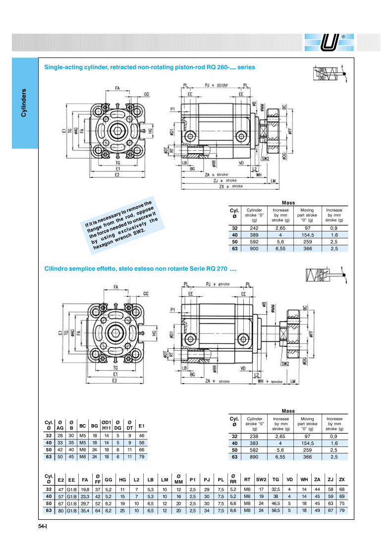
Single-acting cylinder, retracted non-rotating piston-rod RQ 260---- series
Cilindro semplice effetto, stelo esteso non rotante Serie RQ 270 ---
E2 EE FA
47 G1/8 19,8
57 G1/8 23,3
67 G1/8 29,7
80 G1/8 35,4
ØFF
37
42
52
64
Cyl.Ø
ØRR RT SW2 TG VD ZA ZJ ZXWH
32 5,2 M6 17 32,5 4 14 44 58 68
40 5,2 M6 19 38 4 14 45 59 69
50 6,6 M8 24 46,5 5 18 45 63 7563 6,6 M8 24 56,5 5 18 49 67 79
Mass
32 242 2,65 97 0,940 389 4 154,5 1,650 592 5,6 259 2,563 900 6,55 366 2,5
Cyl.ø
Mass
32 238 2,65 97 0,940 383 4 154,5 1,650 582 5,6 259 2,563 890 6,55 366 2,5
Cyl.ø
GG HG
5,2 115,2 15
6,2 19
6,2 25
L2 LB
7 5,37
10
10
5,3
6,5
6,5
LMØ
MM
10 12 2,510 16 2,5
12 20 2,5
12 20 2,5
P1 PJ PL
29 7,530 7,5
30 7,5
34 7,5
If it is necessary to remove the
flange from the rod, oppose
the force needed to unscrew it
by using exclusively the
hexagon wrench SW2.
stroke
stroke
stroke
stroke
stroke
stroke stroke
Cylinderstroke �0�
(g)
Increaseby mm
stroke (g)
Movingpart stroke
�0� (g)
Increaseby mm
stroke (g)
Cylinderstroke �0�
(g)
Increaseby mm
stroke (g)
Movingpart stroke
�0� (g)
Increaseby mm
stroke (g)
Cyl.Ø
ØAG BC BG
ØD1H11
ØDG E1
ØDT
32 28 18 14 5 9 46
40 33 18 14 5 9 56
50 42 24 18 6 11 6663 50 24 18 6 11 79
ØB
M5
M5
M6M6
30
35
4045

ëëó×
Cyl
ind
ers
Tandem cylinder(double thrustand traction force)
Compact cylinders STRONG series - special versions upon request
Codification key
C2 effective stroke front cylinder (mm)
C1 stroke rear cylinder (mm)
Bore
Type
Series
RS 2B 032 0030 0050
*Cyl.
ZAØL
32 44 8840 45 9050 45 9063 49 98
Stainless steel rod1A Female rod3A Male rod
Chromium-plated steel rod2A Female rod4A Male rod
TYPE
SERIES
RS Round tandem cylinderRO Octagonal tandem cylinder
BORE
032-040-050-063 mm
STROKE
Page 45-×
Codification key
RS 2A 032 0080
Stroke (mm)
Bore
Type
Series
STROKE
STROKE STROKE
STROKE
STROKE STROKE
Cylinder with independent rods(multiple position cylinder)
*Cyl. ZAØ
L
32 44 8840 45 9050 45 9063 49 98
TYPE
Stainless steel rod1B Female rod3B Male rod
Chromium-plated steel rod2B Female rod4B Male rod
SERIES
RS Round cylinder with independent rodsRO Octagonal cylinder with independent rods
BORE
032-040-050-063 mm
STROKE 1
Stroke rear cylinder.
STROKE 2
Effective stroke front cylinder.

ëêó×
Cyl
ind
ers
Opposed cylinder
* For all other dimensions please refer to the standard version on pages 48 and 53.
*Cyl.
ZAØL
32 44 8840 45 9050 45 9063 49 98
SERIES
RS Round cylinder with opposed rodsRO Octagonal cylinder with opposed rods
TYPE
Stainless steel rod1C Female rod3C Male rod
Chromium-plated steel rod2C Female rod4C Male rod
BORE
032-040-050-063 mm
STROKE 1
Page 45-×
STROKE 2
Page 45-×
Codification key
C2 Longer stroke (mm)
C1 Shorter stroke (mm)
Bore
Type
Series
RS 2C 040 0020 0040
ëéó×
Cyl
ind
ers
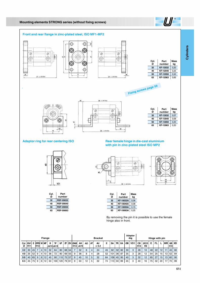
Mounting elements STRONG series (without fixing screws)
Front and rear flange in zinc-plated steel, ISO MF1-MF2
By removing the pin it is possible to use the femalehinge also in front.
Angle bracket in zinc-plated steel, ISO MS1
Adaptor ring for rear centering ISO
32 KF-12032 0,2040 KF-12040 0,2550 KF-12050 0,5063 KF-12063 0,65
Cyl.Ø
Partnumber
Masskg
32 KF-13032 0,0740 KF-13040 0,0950 KF-13050 0,2063 KF-13063 0,20
Cyl.Ø
Partnumber
Masskg
32 KF-10032A 0,0640 KF-10040A 0,0850 KF-10050A 0,1563 KF-10063A 0,25
Cyl.Ø
Partnumber
Masskg
Rear female hinge in die-cast aluminiumwith pin in zinc-plated steel ISO MP2
E W MF UF ZF ZH AT SA TR XA ØB VD1 E FL L MR XD
3 2 30 45 7 4 10 32 64 80 68 54 7 32 6 4 24 45 92 32 82 30 3 26 10 48 22 12 11 45 80
4 0 35 52 9 4 10 36 72 90 69 55 9 36 8 4 28 52 101 36 87 35 3 28 12 54 25 15 13 52 84
5 0 40 65 9 6 12 45 90 110 75 57 9 45 10 5 32 64 109 45 95 40 3 32 12 65 27 15 13 60 90
6 3 45 75 9 6 12 50 100 120 79 61 9 50 12 5 32 74 113 50 99 45 3 40 16 75 32 20 17 70 99
Flange Bracket Hinge with pin
Cyl.Ø
Ød1H11
ØFBH13
ØABH13
AHJs15
RJs14
TFJs14
AO AU± 0.2
E CBH14
UBh14
ØCDH9
Adaptorring
Fixing screws page 59
32 RSF-09032
40 RSF-09040
50 RSF-09050
63 RSF-09063
Cyl.Ø
Partnumber
stroke stroke
stroke
stroke
stroke
ëèó×
Cyl
ind
ers
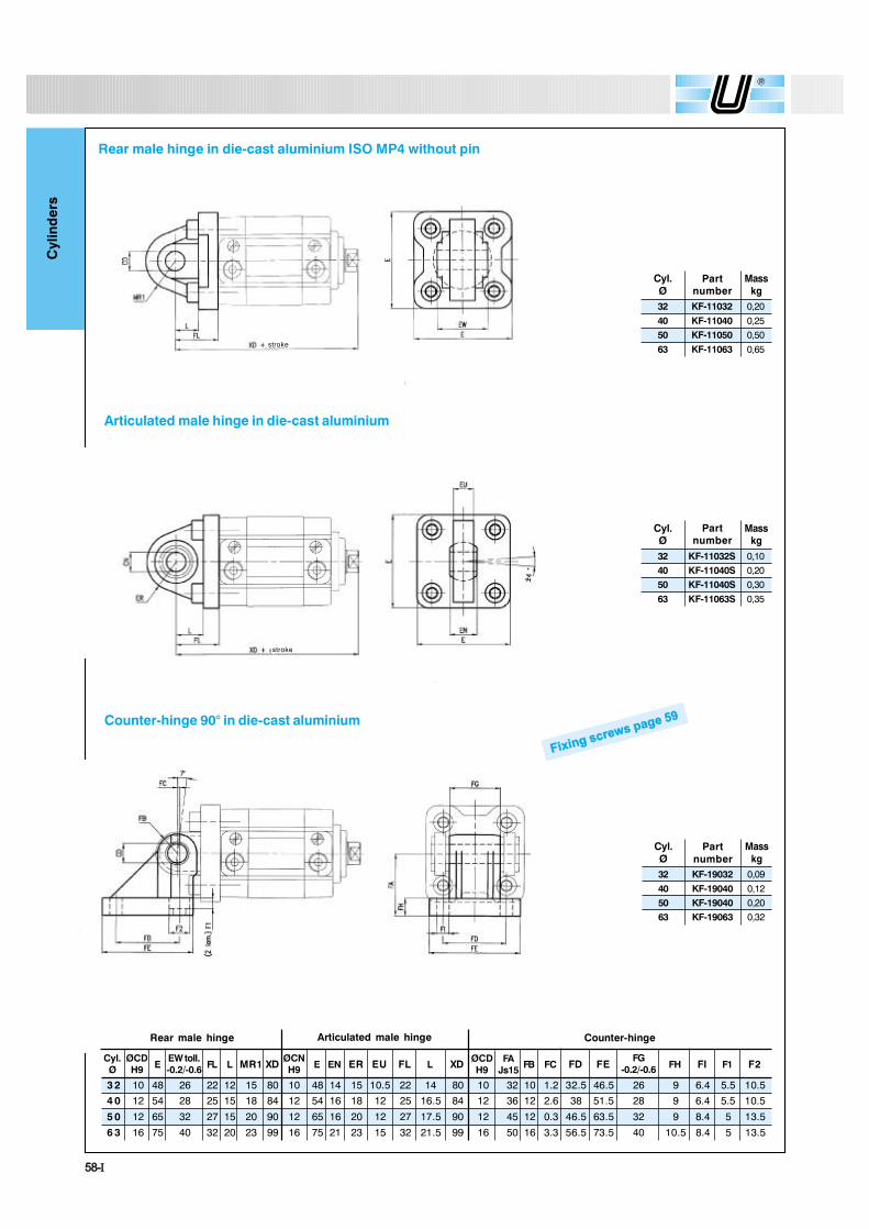
Rear male hinge in die-cast aluminium ISO MP4 without pin
Articulated male hinge in die-cast aluminium
32 KF-11032 0,2040 KF-11040 0,2550 KF-11050 0,5063 KF-11063 0,65
Cyl.Ø
Partnumber
Masskg
32 KF-11032S 0,1040 KF-11040S 0,2050 KF-11040S 0,3063 KF-11063S 0,35
Cyl.Ø
Partnumber
Masskg
32 KF-19032 0,0940 KF-19040 0,1250 KF-19040 0,2063 KF-19063 0,32
Cyl.Ø
Partnumber
Masskg
Ú·¨·²¹ ½®»© °¿¹» ëç
E FL L MR1 XD E EN ER EU FL L XD FB FC FD FE FH FI F1 F2
3 2 10 48 26 22 12 15 80 10 48 14 15 10.5 22 14 80 10 32 10 1.2 32.5 46.5 26 9 6.4 5.5 10.5
4 0 12 54 28 25 15 18 84 12 54 16 18 12 25 16.5 84 12 36 12 2.6 38 51.5 28 9 6.4 5.5 10.5
5 0 12 65 32 27 15 20 90 12 65 16 20 12 27 17.5 90 12 45 12 0.3 46.5 63.5 32 9 8.4 5 13.5
6 3 16 75 40 32 20 23 99 16 75 21 23 15 32 21.5 99 16 50 16 3.3 56.5 73.5 40 10.5 8.4 5 13.5
Cyl.Ø
Rear male hinge
ØCDH9
EW toll.-0.2/-0.6
Articulated male hinge
ØCNH9
Counter-hinge
ØCDH9
FAJs15
FG-0.2/-0.6
stroke
stroke
Counter-hinge 90° in die-cast aluminium
ëçó×
Cyl
ind
ers
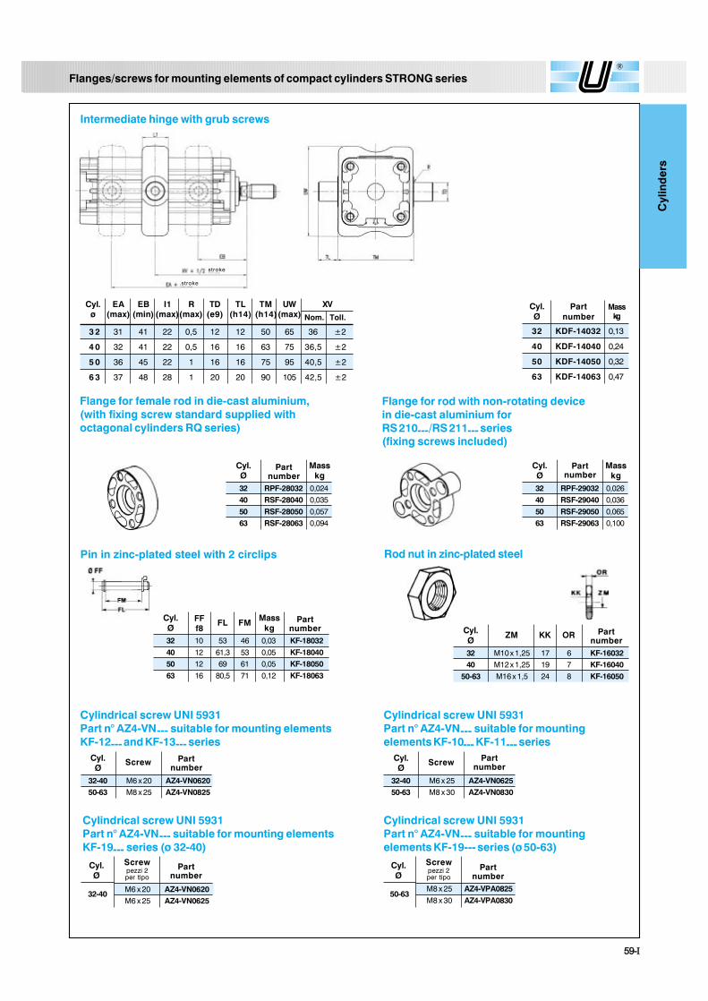
Flanges/screws for mounting elements of compact cylinders STRONG series
Cylindrical screw UNI 5931Part n° AZ4-VN--- suitable for mounting elementsKF-12--- and KF-13--- series
Cylindrical screw UNI 5931Part n° AZ4-VN--- suitable for mounting elementsKF-19--- series (ø 32-40)
Cylindrical screw UNI 5931Part n° AZ4-VN--- suitable for mountingelements KF-10--- KF-11--- series
Cylindrical screw UNI 5931Part n° AZ4-VN--- suitable for mountingelements KF-19--- series (ø 50-63)
Intermediate hinge with grub screws
Cyl. EA EB I1 R TD TL TM UW XVø (max) (min) (max)(max) (e9) (h14) (h14)(max)
3 2 31 41 22 0,5 12 12 50 65 36 ±2
4 0 32 41 22 0,5 16 16 63 75 36,5 ±2
5 0 36 45 22 1 16 16 75 95 40,5 ±2
6 3 37 48 28 1 20 20 90 105 42,5 ±2
Nom. Toll.
32 KDF-14032 0,13
40 KDF-14040 0,24
50 KDF-14050 0,32
63 KDF-14063 0,47
Cyl.Ø
Partnumber
Masskg
Pin in zinc-plated steel with 2 circlips
32-40 M6 x 20 AZ4-VN062050-63 M8 x 25 AZ4-VN0825
Cyl.Ø
Partnumber
Screw
32-40 M6 x 25 AZ4-VN062550-63 M8 x 30 AZ4-VN0830
Cyl.Ø
PartnumberScrew
M6 x 20 AZ4-VN0620M6 x 25 AZ4-VN0625
Cyl.Ø
Partnumber
32-40
Screwpezzi 2per tipo
M8 x 25 AZ4-VPA0825M8 x 30 AZ4-VPA0830
Cyl.Ø
Partnumber
50-63
Screwpezzi 2per tipo
Rod nut in zinc-plated steel
32 M10 x 1,25 17 6 KF-1603240 M12 x 1,25 19 7 KF-16040
50-63 M16 x 1,5 24 8 KF-16050
Cyl.Ø
Partnumber
ZM KK OR32 10 53 46 0,03 KF-1803240 12 61,3 53 0,05 KF-1804050 12 69 61 0,05 KF-1805063 16 80,5 71 0,12 KF-18063
Cyl.Ø
Partnumber
Masskg
FFf8
FL FM
Flange for female rod in die-cast aluminium,(with fixing screw standard supplied withoctagonal cylinders RQ series)
Flange for rod with non-rotating devicein die-cast aluminium forRS 210---/RS 211--- series(fixing screws included)
32 RPF-28032 0,02440 RSF-28040 0,03550 RSF-28050 0,05763 RSF-28063 0,094
Cyl.Ø
Partnumber
Masskg
32 RPF-29032 0,02640 RSF-29040 0,03650 RSF-29050 0,06563 RSF-29063 0,100
Cyl.Ø
Partnumber
Masskg
stroke
stroke
êðó×
Cyl
ind
ers
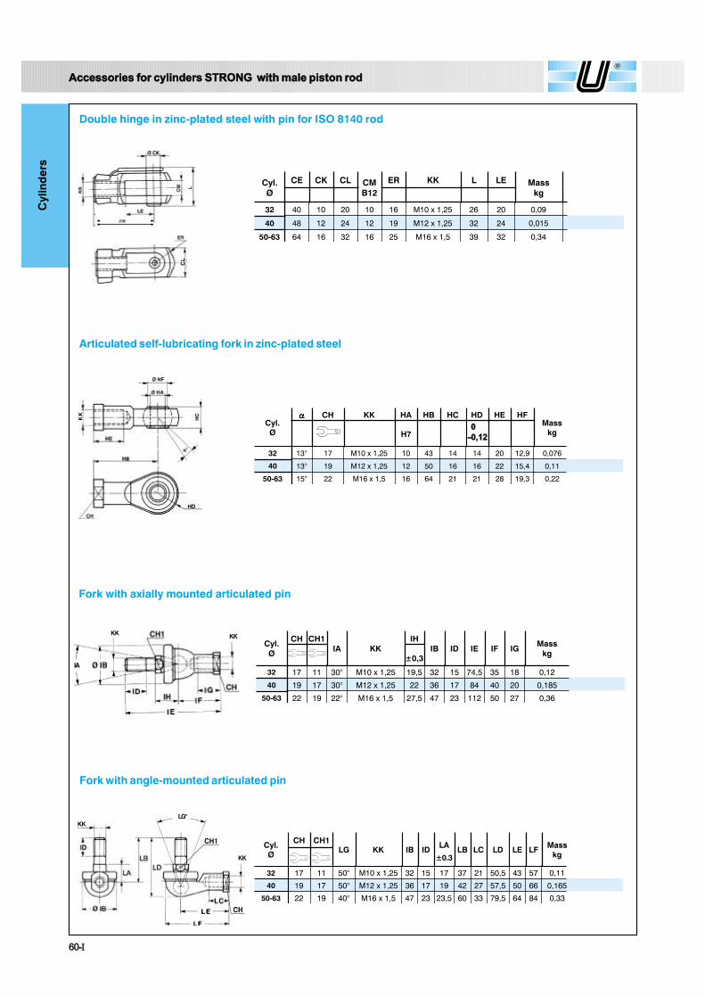
Cyl.Ø
CE CK CL CMB12
ER KK L LE Masskg
32 40 10 20 10 16 M10 x 1,25 26 20 0,09
40 48 12 24 12 19 M12 x 1,25 32 24 0,015
50-63 64 16 32 16 25 M16 x 1,5 39 32 0,34
Double hinge in zinc-plated steel with pin for ISO 8140 rod
ß½½»±®·» º±® ½§´·²¼»® ÍÌÎÑÒÙ ©·¬¸ ³¿´» °·¬±² ®±¼
CL
KKLG°
KK
Cyl.Ø
CH CH1LG KK IB ID LA LB LC LD LE LF Mass
kg
32 17 11 50° M10 x 1,25 32 15 17 37 21 50,5 43 57 0,11
40 19 17 50° M12 x 1,25 36 17 19 42 27 57,5 50 66 0,165
50-63 22 19 40° M16 x 1,5 47 23 23,5 60 33 79,5 64 84 0,33
±0.3
Fork with axially mounted articulated pin
IA
KK KKCyl.Ø
CH CH1IA KK
IH
±0,3IB ID IE IF IG
Masskg
32 17 11 30° M10 x 1,25 19,5 32 15 74,5 35 18 0,12
40 19 17 30° M12 x 1,25 22 36 17 84 40 20 0,185
50-63 22 19 22° M16 x 1,5 27,5 47 23 112 50 27 0,36
Articulated self-lubricating fork in zinc-plated steel
KK
Cyl.Ø
CH KK HA HB HC HD HE HFMass
kgH7
32 13° 17 M10 x 1,25 10 43 14 14 20 12,9 0,076
40 13° 19 M12 x 1,25 12 50 16 16 22 15,4 0,11
50-63 15° 22 M16 x 1,5 16 64 21 21 28 19,3 0,22
ðóðôïî
Fork with angle-mounted articulated pin