specification for casing and tubing 5ct edicion 7.pdf · tubing, and drilling pipe. this standard...
TRANSCRIPT

Specification for Casing and Tubing
API Specification 5CT, Seventh EditionOctober 1, 2001
ISO 11960:2001, Petroleum and Natural GasIndustries—Steel Pipes for Use as Casing and Tubing for Wells
EFFECTIVE DATE: APRIL 1, 2002
PROPOSED NATIONAL ADOPTION

API Specification 5CT / ISO 11960:2001 © American Petroleum Institute
Special Notes
API publications necessarily address problems of a general nature. With respect to particular circumstances,local,state, and federal laws and regulations should be reviewed.
API is not undertaking to meet the duties of employers, manufacturers, or suppliers to warn and properly train andequip their employees, and others exposed, concerning health and safety risks and precautions, nor undertaking theirobligations under local, state, or federal laws.
Information concerning safety and health risks and proper precautions with respect to particular materials andconditions should be obtained from the employer, the manufacturer or supplier of that material, or the material safetydata sheet.
Nothing contained in any API publication is to be construed as granting any right, by implication or otherwise, for themanufacture, sale, or use of any method, apparatus, or product covered by letters patent. Neither should anythingcontained in the publication be construed as insuring anyone against liability for infringement of letters patent.Generally, API standards are reviewed and revised, reaffirmed, or withdrawn at least every five years. Sometimes aone-time extension of up to two years will be added to this review cycle. This publication will no longer be in effect fiveyears after its publication date as an operative API standard or, where an extension has been granted, uponrepublication. Status of the publication can be ascertained from the API Standards Department, telephone (202) 682-8000. A catalog of API publications and materials is published annually and updated quarterly by API, 1220 L Street,N.W., Washington, D.C. 20005.
This document was produced under API standardization procedures that ensure appropriate notification andparticipation in the developmental process and is designated as an API standard. Questions concerning theinterpretation of the content of this standard or comments and questions concerning the procedures under which thisstandard was developed should be directed in writing to the general manager of the Standards Department, AmericanPetroleum Institute, 1220 L Street, N.W., Washington, D.C. 20005. Requests for permission to reproduce or translateall or any part of the material published herein should also be addressed to the director.
API standards are published to facilitate the broad availability of proven, sound engineering and operating practices.These standards are not intended to obviate the need for applying sound engineering judgment regarding when andwhere these standards should be utilized. The formulation and publication of API standards is not intended in any wayto inhibit anyone from using any other practices.
Any manufacturer marking equipment or materials in conformance with the marking requirements of an API standardis solely responsible for complying with all the applicable requirements of that standard. API does not represent,warrant, or guarantee that such products do in fact conform to the applicable API standard.

API Specification 5CT / ISO 11960:2001 © American Petroleum Institute
API Foreword
This standard is under the jurisdiction of the API Standards Subcommittee on Tubular Goods (API C1/SC5). This APIstandard is identical with the English version of ISO 11960:2001. ISO 11960 was prepared by Technical CommitteeISO/TC 67, Materials, equipment and offshore structures for petroleum and natural gas industries, SC 5, Casing,Tubing, and Drilling Pipe.
This standard shall become effective on the date printed on the cover but may be used voluntarily from the date ofpublication.
API publications may be used by anyone desiring to do so. Every effort has been made by the Institute to assure theaccuracy and reliability of the data contained in them; however, the Institute makes no representation, warranty, orguarantee in connection with this publication and hereby expressly disclaims any liability or responsibility for loss ordamage resulting from its use or for the violation of any federal, state, or municipal regulation with which thispublication may conflict.
Suggested revisions are invited and should be submitted to the Upstream Segment, API, 1220 L Street, NW,Washington, DC 20005.

API Specification 5CT / ISO 11960:2001 © American Petroleum Institute
Date of Issue: April 1, 2002Affected Publication: API Specification 5CT, Specification for Casing and Tubing, Seventh Edition
ERRATA
API has agreed to issue the 7th edition of API Spec 5CT as an identical adoption of the 2nd edition of ISO 11960. Afterthe issuance of ISO 11960, several editorial corrections were discovered. In order to keep the ISO and API standardsaligned and identical, it was decided not to incorporate the changes into the 7th edition of API Spec 5CT, but to publishan identical document and this Errata as a separate document at the same time as the 7th edition of 5CT. It isanticipated that ISO will publish an identical Errata (Corrigendum) soon after the publication of this Errata.
Please note that other editorial items of less significance were also identified but determined not appropriate forinclusion in this errata. A listing of the items identified will be maintained on the API web site for reference to thosethat help maintain the document.
1.1 Revise the next to the last paragraph to read ÒFor pipes covered by this International Standard, the sizes,masses, wall thicknesses, grades, and applicable end finish are listed in Tables C.1 to C.3 and E.1 to E.3.
6.1 Change ÒC.1 to C.4Ó and ÒE.1 to E.4Ó.
8.12.2, 2nd line Delete Òand casing accessoriesÓ
8.12.3, 2nd line Delete Òand tubing accessoriesÓ
10.12.2, 2nd paragraph Change to ÒFor threaded pipe, the hydrostatic test pressureÉ.Ó
A.2 Title Change to ÒSR22 Supplementary……and P110 to A.9 (SR16)
A.9.6.1 Delete ÒISO 6892 orÓ
Table C.39, Column 2, < 6-5/8 is for casing, not tubing
Table C.62, Column 1 Combine cells for C90 and T96-Q125 and list as: C90, T95, Q125
Table C67, Box 3, Column 2 Shift all text lines down one line so have alignment with ÒUFÓ and ÒSFÓ, etc., seeTable E.67 for correct format
Table C.67, Box 8, Column 2 In 3rd line after M65 add ÒQuenched and temperedÓ
Table C.79, Box 8, Column 2 In 3rd line after M65 add ÒQuenched and temperedÓ
Figure D.3 Move text ÒOn special clearanceÉ.Ó To below top figure
Figure D.8 Add footnote c to Label 7
Figure D.9 Change to b)Strip specimena
Remove superscript ÒaÓ from ÒRÓ in Figure b)
Figure D.16, Example 5, Stamp Marking Delete 2.15.9 and revise ÒDAÓ to ÒDAdÓ and add newfootnote d. as follows:ÒdExpress alternate drift diameter in mm for pipe manufactured in SIunits and in inches for pipe manufactured in USC units.Ó
Figure D.23 Make the same changes as for Figure D.16

API Specification 5CT / ISO 11960:2001 © American Petroleum Institute
Table E.27, Column 4For 2nd 1.050 Change 1.20 to 1.54For 2nd 1.315 Change 1.80 to 2.24For 2nd 1.660 Change 2.40 to 3.07For 2nd 1.990 Change 2.90 to 3.73
Should be the same values as in column 2
Table E.35 Change the tolerance on Outside diameter to +1/8 in Group 4
Table E.39 Make same changes as done for Table C.39
Table E.62 Make same changes as done for Table C.62
Table E.67, Box 8, Column 2 In 3rd line after M65 add ÒQuenched and temperedÓ
Table E.79 Box 3, Make same changes as done for Table C.67Box 8, Change to be like that in Table C.79Box 16, Change couplings to H40, J55 and K55

© American Petroleum Institute API Specification 5CT / ISO 11960:2001
iii
Contents Page
Foreword...........................................................................................................................................................................vi
Introduction ...................................................................................................................................................................... vii
1 Scope....................................................................................................................................................................12 Conformance ........................................................................................................................................................22.1 Normative references ...........................................................................................................................................22.2 Units of measurement...........................................................................................................................................22.3 Tables and figures ................................................................................................................................................2
3 Normative references ...........................................................................................................................................2
4 Terms, definitions, symbols and abbreviated terms.............................................................................................44.1 Terms and definitions ...........................................................................................................................................44.2 Symbols and abbreviated terms ...........................................................................................................................8
5 Information to be supplied by the purchaser ........................................................................................................95.1 Casing...................................................................................................................................................................95.2 Tubing .................................................................................................................................................................10
6 Process of manufacture......................................................................................................................................126.1 General ...............................................................................................................................................................126.2 Heat treatment ....................................................................................................................................................126.3 Straightening.......................................................................................................................................................136.4 Traceability..........................................................................................................................................................13
7 Material requirements .........................................................................................................................................147.1 Chemical composition.........................................................................................................................................147.2 Tensile properties ...............................................................................................................................................147.3 Charpy V-notch test properties — General requirements ..................................................................................157.4 Charpy V-notch (CVN) — Absorbed energy requirements for coupling stock, coupling blanks and couplings 167.5 Charpy V-notch — Absorbed energy requirements for pipe ..............................................................................177.6 Charpy V-notch test — Absorbed energy requirements for casing and tubing accessories .............................197.7 Hardness maxima...............................................................................................................................................207.8 Hardness variation — Grades C90, T95 and Q125 ...........................................................................................207.9 Process control — Grades C90, T95 and Q125.................................................................................................207.10 Hardenability — Minimum percentage martensite for quenched and tempered products.................................217.11 Grain size — Grades C90 and T95 ....................................................................................................................217.12 Surface condition — Grades L80 9Cr and L80 13Cr..........................................................................................217.13 Flattening — Electric-welded pipe ......................................................................................................................217.14 Sulfide stress corrosion cracking (SSCC) test — Grades C90 and T95............................................................21
8 Dimensions, masses, tolerances, pipe ends and defects ..................................................................................238.1 Labels and sizes .................................................................................................................................................238.2 Dimensions and masses.....................................................................................................................................238.3 Diameter .............................................................................................................................................................238.4 Wall thickness.....................................................................................................................................................248.5 Mass ...................................................................................................................................................................248.6 Length .................................................................................................................................................................248.7 Casing jointers ....................................................................................................................................................248.8 Height and trim of electric-weld flash..................................................................................................................248.9 Straightness........................................................................................................................................................258.10 Drift requirements ...............................................................................................................................................258.11 Tolerances on dimensions and masses .............................................................................................................268.12 Pipe ends ............................................................................................................................................................27

API Specification 5CT / ISO 11960:2001 © American Petroleum Institute
iv
8.13 Defects ...............................................................................................................................................................288.14 Coupling make-up and thread protection........................................................................................................... 29
9 Couplings............................................................................................................................................................299.1 General requirements......................................................................................................................................... 299.2 Alternative grades or heat treatments................................................................................................................ 299.3 Process of manufacture — Groups 1, 2 and 3................................................................................................... 309.4 Process of manufacture — Grade Q125............................................................................................................ 309.5 Mechanical properties ........................................................................................................................................309.6 Dimensions and tolerances................................................................................................................................319.7 Regular couplings...............................................................................................................................................319.8 Special-clearance couplings — Groups 1, 2 and 3............................................................................................ 319.9 Combination couplings.......................................................................................................................................319.10 Reducing couplings ............................................................................................................................................319.11 Seal-ring couplings.............................................................................................................................................319.12 Special-bevel couplings — Groups 1, 2 and 3................................................................................................... 329.13 Threading ...........................................................................................................................................................329.14 Surface inspection..............................................................................................................................................329.15 Measurement of imperfections...........................................................................................................................339.16 Repair and removal of imperfections and defects.............................................................................................. 339.17 Thread surface treatment — Grade Q125 ......................................................................................................... 339.18 Couplings and coupling blank protection — Grade Q125.................................................................................. 33
10 Inspection and testing ........................................................................................................................................3310.1 Test equipment...................................................................................................................................................3310.2 Lot definition for testing of mechanical properties.............................................................................................. 3410.3 Testing of chemical composition ........................................................................................................................ 3410.4 Tensile tests .......................................................................................................................................................3510.5 Flattening test.....................................................................................................................................................3710.6 Hardness test .....................................................................................................................................................3810.7 Impact test ..........................................................................................................................................................4110.8 Grain size determination — Grades C90 and T95............................................................................................. 4310.9 Hardenability — Grades C90 and T95............................................................................................................... 4310.10 Sulfide stress cracking test — Grades C90 and T95......................................................................................... 4310.11 Metallographic evaluation — EW Grades P110 and Q125................................................................................ 4310.12 Hydrostatic test...................................................................................................................................................4310.13 Dimensional testing ............................................................................................................................................4510.14 Visual inspection ................................................................................................................................................4710.15 Non-destructive examination (NDE)...................................................................................................................48
11 Marking...............................................................................................................................................................5311.1 General...............................................................................................................................................................5311.2 Stamp marking requirements .............................................................................................................................5411.3 Stencil marking requirements.............................................................................................................................5511.4 Color identification..............................................................................................................................................5511.5 Thread and end-finish marking — All groups..................................................................................................... 5611.6 Pipe-threader marking requirements — All groups............................................................................................ 56
12 Coating and protection .......................................................................................................................................5712.1 Coatings — All groups........................................................................................................................................5712.2 Thread protectors ...............................................................................................................................................57
13 Documents .........................................................................................................................................................5813.1 Electronic media — All groups ...........................................................................................................................5813.2 Certification — Groups 1, 2 and 3...................................................................................................................... 5813.3 Certification requirements — Grade Q125......................................................................................................... 5813.4 Retention of records ...........................................................................................................................................5814 Minimum facility requirements for various categories of manufacturer ............................................................. 5814.1 Pipe mill ..............................................................................................................................................................5814.2 Processor ...........................................................................................................................................................5914.3 Threader .............................................................................................................................................................5914.4 Coupling, pup-joint, and accessory manufacturer.............................................................................................. 59

© American Petroleum Institute API Specification 5CT / ISO 11960:2001
v
Annex A (normative) Supplementary requirements .......................................................................................................60
Annex B (normative) Purchaser inspection ....................................................................................................................72
Annex C (normative) Tables in SI units ..........................................................................................................................73
Annex D (normative) Figures in SI (USC) units............................................................................................................136
Annex E (normative) Figures in SI (USC) units............................................................................................................158
Annex F (normative) Figures in SI (USC) units ............................................................................................................218
Annex G (normative) Figures in SI (USC) units ...........................................................................................................222
Bibliography ...................................................................................................................................................................235

API Specification 5CT / ISO 11960:2001 © American Petroleum Institute
vi
Foreword
ISO (the International Organization for Standardization) is a worldwide federation of national standards bodies (ISOmember bodies). The work of preparing International Standards is normally carried out through ISO technicalcommittees. Each member body interested in a subject for which a technical committee has been established has theright to be represented on that committee. International organizations, governmental and non-governmental, in liaisonwith ISO, also take part in the work. ISO collaborates closely with the International Electrotechnical Commission (IEC)on all matters of electrotechnical standardization.
International Standards are drafted in accordance with the rules given in the ISO/IEC Directives, Part 3.
Draft International Standards adopted by the technical committees are circulated to the member bodies for voting.Publication as an International Standard requires approval by at least 75% of the member bodies casting a vote.
Attention is drawn to the possibility that some of the elements of this International Standard may be the subject ofpatent rights. ISO shall not be held responsible for identifying any or all such patent rights.
International Standard ISO 11960 was prepared by Technical Committee ISO/TC 67, Materials, equipment andoffshore structures for petroleum and natural gas industries, Subcommittee SC 5, Casing, tubing and drill pipe.
This second edition replaces the first edition (ISO 11960:1996) which has been technically revised. It is the intent ofTC 67 that the first and second editions of ISO 11960 both be applicable, at the user's option, for a period of sixmonths after the date of publication of this second edition, after which the first edition will no longer be applicable.
Annexes A to E form a normative part of this International Standard. Annexes F and G are for information only.

© American Petroleum Institute API Specification 5CT / ISO 11960:2001
vii
Introduction
This International Standard is based on API 5CT (Specification for Casing and Tubing).
Users of this International Standard should be aware that further or differing requirements may be needed forindividual applications. This International Standard is not intended to inhibit a vendor from offering, or the purchaserfrom accepting, alternative equipment or engineering solutions for the individual application. This may be particularlyapplicable where there is innovative or developing technology. Where an alternative is offered, the vendor shouldidentify any variations from this International Standard and provide details.
This International Standard includes requirements of various nature. These are identified by the use of certain verbalforms:
SHALL is used to indicate that a provision is MANDATORY;
SHOULD is used to indicate that a provision is not mandatory, but RECOMMENDED as good practice;
MAY is used to indicate that a provision is OPTIONAL.

API Specification 5CT / ISO 11960:2001 © American Petroleum Institute
viii
Special Notes
API publications necessarily address problems of a general nature. With respect to particular circumstances,local,state, and federal laws and regulations should be reviewed.
API is not undertaking to meet the duties of employers, manufacturers, or suppliers to warn and properly train andequip their employees, and others exposed, concerning health and safety risks and precautions, nor undertaking theirobligations under local, state, or federal laws.
Information concerning safety and health risks and proper precautions with respect to particular materials andconditions should be obtained from the employer, the manufacturer or supplier of that material, or the material safetydata sheet.
Nothing contained in any API publication is to be construed as granting any right, by implication or otherwise, for themanufacture, sale, or use of any method, apparatus, or product covered by letters patent. Neither should anythingcontained in the publication be construed as insuring anyone against liability for infringement of letters patent.Generally, API standards are reviewed and revised, reaffirmed, or withdrawn at least every five years. Sometimes aone-time extension of up to two years will be added to this review cycle. This publication will no longer be in effect fiveyears after its publication date as an operative API standard or, where an extension has been granted, uponrepublication. Status of the publication can be ascertained from the API Standards Department, telephone (202) 682-8000. A catalog of API publications and materials is published annually and updated quarterly by API, 1220 L Street,N.W., Washington, D.C. 20005.
This document was produced under API standardization procedures that ensure appropriate notification andparticipation in the developmental process and is designated as an API standard. Questions concerning theinterpretation of the content of this standard or comments and questions concerning the procedures under which thisstandard was developed should be directed in writing to the general manager of the Standards Department, AmericanPetroleum Institute, 1220 L Street, N.W., Washington, D.C. 20005. Requests for permission to reproduce or translateall or any part of the material published herein should also be addressed to the director.
API standards are published to facilitate the broad availability of proven, sound engineering and operating practices.These standards are not intended to obviate the need for applying sound engineering judgment regarding when andwhere these standards should be utilized. The formulation and publication of API standards is not intended in any wayto inhibit anyone from using any other practices.
Any manufacturer marking equipment or materials in conformance with the marking requirements of an API standardis solely responsible for complying with all the applicable requirements of that standard. API does not represent,warrant, or guarantee that such products do in fact conform to the applicable API standard.

© American Petroleum Institute API Specification 5CT / ISO 11960:2001
1
Petroleum and natural gas industries — Steel pipes for use as casingor tubing for wells
1 Scope
1.1 This International Standard specifies the technical delivery conditions for steel pipes (casing, tubing, plain endcasing liners and pup-joints) and accessories. This International Standard is applicable to the following connections inaccordance with ISO 10422 or API Spec 5B:
short round thread casing (STC); long round thread casing (LC); buttress thread casing (BC); extreme-line casing (XC); non-upset tubing (NU); external upset tubing (EU); integral joint tubing (IJ).
For such connections, this International Standard specifies the technical delivery conditions for couplings and threadprotection.
For pipes covered by this International Standard, the sizes, masses, wall thicknesses, grades and applicable endfinishes are defined.
This International Standard may also be applied to tubulars with connections not covered by ISO/API standards.
1.2 The four groups of products to which this International Standard is applicable include the following grades ofpipe:
Group 1: All casing and tubing in Grades H, J, K and N; Group 2: All casing and tubing in Grades C, L, M and T; Group 3: All casing and tubing in Grade P; Group 4: All casing in Grade Q.
1.3 Casing sizes larger than Label 1: 4-1/2 but smaller than Label 1: 10-3/4 may be specified by the purchaser to beused in tubing service, see Tables C.1, C.24, C.30 and C.31 or Tables E.1, E.24, E.30 and E.31.
1.4 Supplementary requirements that may optionally be agreed between purchaser and manufacturer, for non-destructive examination, coupling blanks, upset casing, electric-welded casing, impact testing, seal ring couplings andcertificates are given in annex A.
1.5 This International Standard is not applicable to threading requirements.
NOTE Dimensional requirements on threads and thread gauges, stipulations on gauging practice, gauge specifications, as wellas instruments and methods for inspection of threads are given in ISO 10422 or API Spec 5B. Connections machined to either ofthese specifications are the same for practical purposes and are totally interchangeable.
American Petroleum Institute
API Specification 5CT / ISO 11960:2001 © American Petroleum Institute
2
2 Conformance
2.1 Normative references
In the interests of worldwide application of this International Standard, ISO/TC 67 has decided, after detailed technicalanalysis, that certain of the normative documents listed in clause 3 and prepared by ISO/TC 67 or other ISO TechnicalCommittee are interchangeable in the context of the relevant requirement with the relevant document prepared by theAmerican Petroleum Institute (API), the American Society for Testing and Materials (ASTM) or the American NationalStandards Institute (ANSI). These latter documents are cited in the running text following the ISO reference andpreceded by “or”, for example “ISO XXXX or API YYYY”. Application of an alternative normative document cited in thismanner will lead to the same results as the use of the preceding ISO reference. These documents are thus consideredinterchangeable in practice.
2.2 Units of measurement
In this International Standard, data are expressed in both the International System (SI) of units and the United StatesCustomary (USC) system of units. For a specific order item, it is intended that only one system of units be used,without combining data expressed in the other system.
Products manufactured to specifications expressed in either of these unit systems shall be considered equivalent andtotally interchangeable. Consequently, compliance with the requirements of this International Standard as expressed inone system provides compliance with requirements expressed in the other system.
For data expressed in the SI, a comma is used as the decimal separator and a space as the thousands separator. Fordata expressed in the USC system, a dot (on the line) is used as the decimal separator and a space as the thousandsseparator.
In the text, data in SI units are followed by data in USC units in brackets.
2.3 Tables and figures
Separate tables for data expressed in SI units and USC units are given in annex C and annex E respectively. For aspecific order item, only one unit system shall be used.
Figures are contained in annex D and express data in both SI and USC units.
3 Normative references
The following normative documents contain provisions which, through reference in this text, constitute provisions of thisInternational Standard. For dated references, subsequent amendments to, or revisions of, any of these publications donot apply. However, parties to agreements based on this International Standard are encouraged to investigate thepossibility of applying the most recent editions of the normative documents indicated below. For undated references,the latest edition of the normative document referred to applies. Members of ISO and IEC maintain registers ofcurrently valid International Standards.
ISO 31-0, Quantities and units—Part 0: General principles
ISO 643, Steels—Micrographic determination of the ferritic or austenitic grain size
ISO 6506-1, Metallic materials—Brinell Hardness test—Part 1:Test method
ISO 6508-1, Metallic materials—Rockwell Hardness test—Part 1:Test method (Scales A, B, C, D, E, F, G, H, K, N, T
ISO 6892, Metallic materials—Tensile testing at ambient temperature

© American Petroleum Institute API Specification 5CT / ISO 11960:2001
3
ISO 7500-1, Metallic materials—Verification of static uniaxial testing machines—Part 1: Tensile/compression testingmachines—Verification and calibration of the force-measuring system
ISO 9303, Seamless and welded (except submerged arc-welded) steel tubes for pressure purposes—Full peripheralultrasonic testing for the detection of longitudinal imperfections
ISO 9304, Seamless and welded (except submerged arc-welded) steel tubes for pressure purposes—Eddy currenttesting for the detection of imperfections
ISO 9305, Seamless steel tubes for pressure purposes—Full peripheral ultrasonic testing for the detection oftransverse imperfections
ISO 9402, Seamless and welded (except submerged arc-welded) steel tubes for pressure purposes—Full peripheralmagnetic transducer/flux leakage testing of ferromagnetic steel tubes for the detection of longitudinal imperfections
ISO 9598, Seamless steel tubes for pressure purposes—Full peripheral magnetic transducer/flux leakage testing offerromagnetic steel tubes for the detection of transverse imperfections
ISO 9764, Electric resistance and induction welded steel tubes for pressure purposes—Ultrasonic testing of the weldseam for the detection of longitudinal imperfections
ISO 10400, Petroleum and natural gas industries—Formulae and calculation for casing, tubing, drill pipe and line pipeproperties
ISO 10422, Petroleum and natural gas industries—Threading, gauging and thread inspection of casing, tubing and linepipe threads—Specification
ISO 10474, Steel and steel products—Inspection documents
ISO 11484, Steel tubes for pressure purposes—Qualification and certification of non-destructive testing (NDT)personnel
ISO 13665, Seamless and welded steel tubes for pressure purposes—Magnetic particle inspection of the tube body forthe detection of surface imperfections
ISO 13678, Petroleum and natural gas industries—Evaluation and testing of thread compounds for use with casing,tubing and line pipe
ISO/TR 9769, Steel and iron—Review of available methods of analysis
ANSI-ASNT SNT-TC-1A:1984, Personnel qualifications and certification in non.destructive testing
ANSI-NACE TM0177:1996, Laboratory testing of metals for resistance to sulfide stress cracking at ambienttemperature in H2S environment
API Bul 5C2, Bulletin on performance properties of casing, tubing and drill pipe
API Bul 5C3, Bulletin on formulas and calculations for casing, tubing, drill pipe and line pipe properties (plusSupplement 1)
API RP 5A3, Bulletin on thread compounds for casing, tubing and line pipe
A PI S pec 5B , S peci ficati on for threadi ng, gauging and thread inspecti on of casi ng, tubing and li ne pi pe threads
API Std 5T1, Imperfection technology
ASTM A370, Standard test methods and definitions for mechanical testing of steel products

API Specification 5CT / ISO 11960:2001 © American Petroleum Institute
4
ASTM A751, Methods, practices and definitions for chemical analysis of steel products
ASTM A941, Terminology relating to steel, stainless steel, related alloys and ferro-alloys
ASTM E4, Practices for load verification of testing machines
ASTM E10, Standard method of test for Brinell hardness of metallic materials
ASTM E18, Standard methods of test for Rockwell hardness and Rockwell superficial hardness of metallic materials
ASTM E23, Standard test methods for notched bar impact testing of metallic materials
ASTM E29, Practice for using significant digits in test data to determine conformance with specifications
ASTM E83, Standard practice for verification and classification of extensometers
ASTM E112, Methods for determining average grain size
ASTM E213, Standard practice for ultrasonic examination of metal pipe and tubing
ASTM E273, Standard practice for ultrasonic examination of longitudinal welded pipe and tubing
ASTM E309, Standard practice for eddy-current examination of steel tubular products using magnetic saturation
ASTM E570, Standard practice for flux leakage examination of ferro-magnetic steel tubular products
ASTM E709, Standard practice for magnetic particle examination
4 Terms, definitions, symbols and abbreviated terms
4.1 Terms and definitions
For the purposes of this International Standard, the terms and definitions in ASTM A941 for heat treatment operationsand the following apply.
4.1.1carloadquantity of pipe loaded on a railway car for shipment from the pipe-making facilities
4.1.2casingpipe run from the surface and intended to line the walls of a drilled well
4.1.3casing and tubing accessoryone-piece tubular section used in a pipe string to provide mechanical and pressure integrity within the pipe string andfacilitate the performance of some other function required of that pipe string
NOTE Examples of accessories are: crossover connectors, swages, nipples, flow couplings, blast joints, etc. Accessoriesexclude the other tubular products specifically defined in this International Standard or products included in other ISO (API)specifications.
4.1.4connectionthreaded assembly of tubular components

© American Petroleum Institute API Specification 5CT / ISO 11960:2001
5
4.1.5controlled coolingcooling from an elevated temperature in a pre-determined manner to avoid hardening, cracking or internal damage, orto produce a desired microstructure or mechanical properties
4.1.6couplinginternally threaded cylinder for joining two lengths of threaded pipe
4.1.7coupling blankunthreaded material used to produce an individual coupling
4.1.8coupling stocktubular used for the manufacture of coupling blanks
4.1.8defectimperfection of sufficient magnitude to warrant rejection of the product based on criteria defined in this InternationalStandard
4.1.9electric-welded pipepipe having one longitudinal seam formed by electric-resistance or electric-induction welding, without the addition offiller metal, wherein the edges to be welded are mechanically pressed together and the heat for welding is generatedby the resistance to flow of electric current
4.1.10handling tightsufficiently tight that the coupling cannot be removed except by the use of a wrench
4.1.11heatmetal produced by a single cycle of a batch melting process
4.1.12heat analysischemical analysis representative of a heat as reported by the metal producer
4.1.13imperfectiondiscontinuity in the product wall or on the product surface that can be detected by a NDE method included in TableC.61 or Table E.61 of this International Standard
4.1.14inspectionprocess of measuring, examining, testing, gauging or otherwise comparing a unit of product with the applicablerequirements
4.1.15inspection lotdefinite quantity of product manufactured under conditions that are considered uniform for the attribute to be inspected
4.1.16inspection lot sampleone or more units of product selected from an inspection lot to represent that inspection lot

API Specification 5CT / ISO 11960:2001 © American Petroleum Institute
6
4.1.17inspection lot sizenumber of units of product in an inspection lot
4.1.18interrupted quenchingquenching in which the pipe being quenched is removed from the quenching medium while the pipe is at a temperaturesubstantially higher than that of the quenching medium
4.1.19ISO/API threadsthreads as specified in ISO 10422 or API Spec 5B
4.1.20label 1dimensionless designation for the size or specified outside diameter that may be used when ordering pipe
4.1.21label 2dimensionless designation for the mass per unit length or wall thickness that may be used when ordering pipe
4.1.22lengthpiece of pipe that may be plain-end, threaded, or threaded and coupled, that is in accordance with the rangerequirements in Table C.30 or Table E.30 of this International Standard
4.1.23linear imperfectionimperfection which includes, but is not limited to, seams, laps, cracks, plug scores, cuts and gouges
NOTE See API Std 5T1.
4.1.24manufacturerone or more of the following, depending on the context: pipe mill; processor; threader; coupling manufacturer, pup-jointmanufacturer; accessory manufacturer
NOTE See clause 14.
4.1.25non-linear imperfectionimperfection which includes, but is not limited to, pits and round bottom die stamping
NOTE See API Std 5T1.
4.1.26pipecasing, tubing, plain-end casing liners and pup-joints as a group
4.1.27pipe millfirm, company or corporation that operates pipe-making facilities
4.1.28plain-end casing linercasing provided unthreaded and with a wall thickness often greater than that specified for J55
4.1.29processorfirm, company or corporation that operates facilities capable of heat-treating pipe made by a pipe mill

© American Petroleum Institute API Specification 5CT / ISO 11960:2001
7
4.1.30productpipe, coupling, accessory, coupling stock or coupling blank, either individually or collectively as applicable
4.1.31pup-jointcasing, tubing or plain-end casing liner of length shorter than Range 1
4.1.32purchaserparty responsible for both the definition of requirements for a product order and for payment for that order
4.1.33quench crackcrack in steel resulting from stresses produced during the transformation from austenite to martensite
NOTE This transformation is accompanied by an increase in volume.
4.1.34seamless pipewrought steel tubular product made without a weld seam
NOTE It is manufactured by hot-working steel, and if necessary, by subsequently cold-working or heat-treating, or acombination of these operations, to produce the desired shape, dimensions and properties.
4.1.35special end finishthreads with thread form and features, manufacturing specifications, dimensions, connection make-up andperformance properties which are beyond the scope of this International Standard
4.1.36special processesfinal operations which are performed during pipe manufacturing that affect the attributes of product, except itschemistry and dimensions
NOTE These special processes are:
Manufacturing conditions Special processes
Seamless, as-rolled — Final re-heating practice and hot sizing orstretch-reducing.
— If applicable, upsetting, coldfinishing.
— Non-destructive examination
Seamless, heat-treated — Heat treatment
— Non-destructive examination
Electric-weld, as-rolled — Sizing and seam welding
— If applicable, seam heat treatment andupsetting
— Non-destructive examination
Electric-weld, heat-treated — Seam welding and full-body heat treatment
— Non-destructive examination

API Specification 5CT / ISO 11960:2001 © American Petroleum Institute
8
4.1.37thread protectorcap or insert used to protect threads and seals during handling, transportation and storage
4.1.38tubingpipe placed within a well and serving to produce well fluids or to inject fluids
4.1.39upper critical temperatureAr3
temperature at which austenite begins to transform to ferrite during cooling
4.2 Symbols and abbreviated terms
BC buttress thread casing connection
CV Charpy V-notch impact test minimum absorbed energy
D specified outside diameter for pipe
d calculated inside diameter
EMI electromagnetic inspection
EU external upset tubing connection
EW electric-welded process
HBW Brinell hardness, when testing with a tungsten carbide ball
HBS Brinell hardness, when testing with a steel ball
HRC Rockwell hardness C-scale
ID inside diameter
IJ integral joint tubing connection
k a constant used in the calculation of elongation
LC long round thread casing connection
N ⟨heat-treat process⟩ full-length normalized
N&T normalized and tempered
NDE non-destructive examination
NU non-upset tubing connection
OD outside diameter
Q quenched and tempered
S seamless process
Sc minimum acceptable result of the ANSI-NACE TM0177:1996 Method B test
SCC special clearance coupling
SSCC sulfide stress corrosion cracking

© American Petroleum Institute API Specification 5CT / ISO 11960:2001
9
STC short round thread casing connection
t specified wall thickness
T&C threaded and coupled
USC United States customary (units)
UT ultrasonic testing
W specified outside diameter for ISO/API thread couplings other than special clearance couplings
Wc specified outside diameter of special clearance couplings
XC extreme line casing connection
YSmin specified minimum yield strength
5 Information to be supplied by the purchaser
5.1 Casing
5.1.1 When enquiring or placing orders for pipe to be manufactured in accordance with this International Standard,the purchaser shall specify the following:
Requirement ReferenceStandard ISO 11960 or API 5CTQuantityType of pipe or couplings
Casing:Threaded or plain-end 8.12Type of connection: round (short or long), buttress,
extreme-line threads, or other connection8.12, Table C.1 or Table E.1
With or without couplings 8.12Special clearance couplings 9.8, Tables C.1, C.36 or Tables E.1,
E.36
Liners: 8.12.1, Table C.2 or Table E.2Label 1 or specified outside diameter Tables C.1, C.2 or Tables E.1, E.2Label 2 or specified mass or wall thickness Tables C.1, C.2 or Tables E.1, E.2Grade and type where applicable Tables C.1, C.2, C.5 or Tables E.1,
E.2, E.5Range length 8.6, Table C.30 or Table E.30Seamless or electric-welded 6.1, Table C.4 or Table E.4Critical thickness for special end-finish couplings, stock or blanks 7.6.6Critical thickness for special end-finish accessories 7.6.6Wall thickness verification of special end-finish accessories 10.13.4Delivery date and shipping instructionsInspection by purchaser Annex B
5.1.2 The purchaser should also state on the purchase agreement his requirements concerning the followingstipulations, which are at the purchaser’s option:
Requirement ReferenceHeat treatment 6.2Lower alternative impact test temperature 7.3.7Casing jointers 8.7

API Specification 5CT / ISO 11960:2001 © American Petroleum Institute
10
Alternative drifting requirements 8.10Casing with couplings detached 8.14
Coupling make-up (other than power-tight) 8.14Coupling blanks 9.2, A.3 (SR9)Seal ring couplings 9.11, A.7 (SR13)Heat and supplementary analyses 10.3Additional markings 11Pipe coatings 12.1Material certification 13.2, A.8 (SR15)
5.1.3 The following may be agreed between purchaser and manufacturer:
Requirement ReferenceCold rotary straightening - Q125 Grade 6.3Statistical impact testing 7.3.8, A.6 (SR12)Impact of Group 1 non-heat-treated pipe 7.5.1, A.9 (SR16)Sulfide stress cracking test - C90 and T95 Grade 7.14Length of accessories 8.6Thread and storage compound 8.14Waiving NDE of Group 1 couplings in Grades H40, J55 and K55 9.14.3Coupling thread plating - Q125 Grade only 9.17Additional hardness testing - Grades M65 and L80 10.6.2Additional hardness testing - C90 and T95 Grade 10.6.4Reduced section tensile specimens - Q125 Grade 10.4.6Hydrostatic pressure test for handling-tight make-up, accessories and 10.12.2Alternative hydrostatic test pressures 10.12.3Plain-end Q125 casing hydrostatic testing 10.12.2Non-destructive examination 10.15, A.1 (SR1), A.2 (SR2), A.4 (SR10)
and A.5 (SR11)Marking requirements 11.1Thread protectors 12.2Coupling blanks - Q125 Grade only A.3 (SR9)Upset casing - Q125 Grade only A.4 (SR10)Electric-weld casing - P110 and Q125 Grade A.5 (SR11)
Alternative F factor in SR 12 - Q125 Grade A.6 (SR12.2)Special end-finish for casing, couplings, pup-joints or accessories 8.12.8, 9.13.2Quality assurance requirementsSpecial wall thickness for Grades C90, T95 and Q125 8.2
5.2 Tubing
5.2.1 When enquiring or placing orders for pipe to be manufactured in accordance with this International Standard,the purchaser shall specify the following:
Requirement ReferenceStandard ISO 11960 or API 5CTQuantityType of pipe or couplings
Tubing:Non-upset, external-upset or integral joint Table C.3 or Table E.3Threaded, plain-end, or other connection 8.12With or without couplings 8.12Special bevel couplings 9.12, Tables C.3, C.37 and C.38
or Tables E.3, E.37 and E.38

© American Petroleum Institute API Specification 5CT / ISO 11960:2001
11
Special clearance couplings 9.8, Tables C.3, C.38or Tables E.3 and E.38
Label 1 or specified outside diameter Table C.3 or Table E.3Label 2 or specified mass or wall thickness Table C.3 or Table E.3Grade and type, where applicable Table C.3 or Table E.3, Table C.5 or
Table E.5Range length 8.6, Table C.30 or Table E.30Seamless or electric-welded 6.1, Table C.4 or Table E.4Critical thickness for special end-finish couplings, stock or blanks 7.4.6Critical thickness for accessory material 7.6.6Wall thickness verification of special end-finish accessories 10.13.4Delivery date and shipping instructionsInspection by purchaser Annex B
5.2.2 The purchaser should also state on the purchase agreement his requirements concerning the followingstipulations, which are at the purchaser’s option:
Requirement ReferenceHeat treatment 6.2Upset length—Standard or extended 8.11.6Rounded nose 8.12.4Coupling make-up (other than power-tight) 8.14Tubing with couplings detached 8.14Seal ring couplings 9.11, A.7 (SR13)Heat and supplementary analyses 10.3Additional markings 11Pipe coatings 12.1Material certification 13.2, A.8 (SR15)
5.2.3 The following may be agreed between purchaser and manufacturer:
Requirement ReferenceStatistical impact testing 7.3.8, A.6 (SR12)Impact testing of Group 1 pipe 7.5.1, A.9 (SR16)Sulfide stress cracking test—C90 and T95 Grade 7.14Length of accessories 8.6Thread and storage compound 8.14Special end-finish for tubing, couplings or accessories 8.12.8, 9.13.3Waiving NDE of Group1 couplings in Grades H40, J55 and K55 9.14.3Additional hardness testing—Grades M65 and L80 10.6.2Additional hardness testing—C90 and T95 Grade 10.6.4Hydrostatic pressure test for handling-tight make-up and pup-joints 10.12.2Alternative hydrostatic test pressures 10.12.3Non-destructive examination 10.15, A.1 (SR1), A.2 (SR2),
A.4 (SR10) and A.5 (SR11)Marking requirements 11.1Thread protectors 12.2Electric-weld tubing—Grade P110 A.5 (SR11)Special end-finish tubing, couplings, pup-joints and accessories 8.12.8, 9.13.3Quality assurance requirementsSpecial wall thickness for Grades C90 and T95 8.2Casing used for tubing 8.2, Table C.30 or Table E.30

API Specification 5CT / ISO 11960:2001 © American Petroleum Institute
12
6 Process of manufacture
6.1 General
The various grades and groups of pipe furnished to this International Standard shall be made to a fine-grain practice.Steel made to a fine-grain practice contains one or more grain-refining elements, such as aluminium, niobium(columbium), vanadium or titanium in amounts intended to result in the steel having a fine austenitic grain size.
Pipe furnished to this International Standard shall be made by the seamless or electric-weld process as shown inTable C.1 or Table E.1 and as specified on the purchase agreement. Pup-joints shall be made from standard casing ortubing or by machining thick-wall casing, tubing or bar stock. Couplings shall be manufactured by one of the processeslisted in 9.3 or 9.4. Cold-drawn tubular products without appropriate heat treatment are not acceptable.
Casing and tubing accessories shall be seamless and made from standard casing or tubing, or by machining thick-wallcasing, tubing or mechanical tubes, or bar stock or hot forgings.
Electric-welded Grade P110 pipe and Grade Q125 casing shall be provided only when the supplementary requirementin A.5 (SR11) is specified on the purchase agreement.
Grade Q125 upset casing shall be provided only when the supplementary requirement in A.4 (SR10) is specified on thepurchase agreement.
6.2 Heat treatment
6.2.1 General
Product shall be heat-treated in accordance with a documented procedure as stipulated in Table C.4 or Table E.4 forthe particular grade and type specified on the purchase agreement. Heat-treated upset pipe shall be heat-treated fulllength after upsetting. Product requiring heat treatment shall be heat-treated the full length. Individually heat-treatedcoupling blanks are acceptable. All pipe processed through a hot-stretch mill (i.e. stretch-reduced) shall be considerednormalized, provided the exit temperature is above the upper critical temperature (Ar3) for the steel being processed,
and the pipe is air-cooled.
The weld seam of electric-welded pipe shall be heat-treated after welding to a minimum temperature of 540°C(1 000°F) or processed in such a manner that no untempered martensite remains.
6.2.2 Group 1
Grade N80 Type 1 product shall be normalized or, at the manufacturer's option, shall be normalized and tempered.Grade N80Q product shall be quenched and tempered (including the interrupted quenching followed by controlledcooling method) full length. Grade J55 and K55 casing and Grade J55 tubing shall be heat-treated if so specified onthe purchase agreement.
6.2.3 Group 2
When requested by the purchaser, the manufacturer shall produce evidence to show that the tempering practice willresult in the pipe attaining the minimum tempering temperature.
Grade L80 13Cr may be subject to embrittlement when tempered below 620°C (1 150°F). When all product meets therequirements in 7.3, 7.4.5, 7.5.3 and 10.7, no further precautions are necessary.
NOTE In this International Standard when the symbol L80 is used alone it covers Grades L80 Type 1, L80 9Cr andL80 13Cr.

© American Petroleum Institute API Specification 5CT / ISO 11960:2001
13
6.2.4 Groups 3 and 4
Product furnished to this International Standard shall be quenched and tempered.
6.3 Straightening
6.3.1 Groups 1 and 3
No specific methods are required.
6.3.2 Grades M65 and L80
Grades M65 and L80 shall not be subjected to cold working after the final heat treatment, except for that which isincidental to normal straightening operations. Grades M65 and L80 pipe rotary-straightened at temperatures less than480°C (900°F) shall not contain roll marks that exceed the maximum hardness specified in Table C.6 or Table E.6;however:
Roll marks that are not detectable by feel and have no measurable surface deformation are acceptable withoutfurther evaluation;
Roll marks that are not more severe than those previously evaluated and verified by the manufacturer in adocumented procedure not to exceed the maximum hardness specified in Table C.6 or Table E.6 are acceptablewithout further evaluation.
Pipe with severe roll marks shall be either rejected or stress-relieved at 480°C (900°F) minimum.
6.3.3 Grade C95
Grade C95 pipe shall be subjected to no tensile or expansion cold-working, except that which is incidental to normalstraightening operations, and to no more than 3% compressive cold-working, after the final tempering operation.
6.3.4 Grades C90 and T95
Grades C90 and T95 pipe may be subjected to cold rotary-straightening if, subsequent to the cold rotary-straighteningoperation, the pipe is heated to a minimum temperature of 480°C (900°F) for stress-relieving. When necessary, lightgag-straightening for Grades C90 and T95 shall be permitted.
6.3.5 Grade Q125
Gag-press straightening or hot rotary-straightening at 400°C (750°F) minimum at the end of rotary-straightening(unless a higher minimum temperature is specified on the purchase agreement) is acceptable. If hot rotary-straightening is not possible, the pipe may be cold rotary-straightened provided it is then stress-relieved at 510°C(950°F) or higher. Pipe may be cold rotary-straightened without subsequent stress-relieving only by agreementbetween purchaser and manufacturer.
6.4 Traceability
6.4.1 General
The manufacturer shal l establi sh and fol l ow procedures for maintai ni ng heat and/or lot i denti ty unti l all requi red heatand/or l ot tests are performed and conformance w ith specificati on requi rements has been shown.
6.4.2 Serialization of Grades C90, T95 and Q125
The serial number shall be marked on products as specified below. It is the responsibility of the manufacturer tomaintain the identification of material until it is received by the purchaser.

API Specification 5CT / ISO 11960:2001 © American Petroleum Institute
14
Each length of pipe shall be uniquely numbered so that test data can be related to individual lengths. In addition, whensupplementary requirement A.6 (SR12) is specified, the number shall identify the sequence in which the lengths weretempered in order to allow re-test in accordance with A.6.3 (SR12.3).
Each tube length of coupling, pup-joint or accessory material shall be uniquely numbered so that test data can berelated to individual lengths. When cut from material that has been heat-treated full length, the pieces shall be markedwith the serial number of the full length piece. When heat-treated in coupling blank or individual lengths, each heat-treat lot (see 10.2.3) shall be uniquely numbered. Additionally, when coupling, pup-joint or accessory material incoupling blank or individual lengths is heat-treated as a unit in a continuous process-run, the pieces within the lot shallbe sequentially numbered in the order in which they are heat-treated.
7 Material requirements
7.1 Chemical composition
P roduct shall conform to the requirements specified i n Table C.5 or Table E .5 for the grade and type speci fi ed.
7.2 Tensile properties
7.2.1 General
Product shall conform to the tensile requirements specified in Table C.6 or Table E.6.
The tensile properties of upset casing and tubing, except elongation of the upset ends, shall comply with therequirements given for the pipe body. In case of dispute, the properties (except elongation) of the upset shall bedetermined from a tensile test specimen cut from the upset. A record of such tests shall be available to the purchaser.
7.2.2 Elongation—All groups
The minimum elongation shall be that determined by the following equation:
e = k ⋅A0,2
U0,9
where
e is the minimum gauge length extension in 50,8 mm (2.0 in) in percent rounded to the nearest 0,5% below10% and to the nearest unit percent for 10% and larger;
k is a constant: 1 944 (625 000);
A is the cross-sectional area of the tensile test specimen in square millimetres (square inches), based onspecified outside diameter or nominal specimen width and specified wall thickness, rounded to the nearest10 mm2 (0.01 in2), or 490 mm2 (0.75 in2) whichever is smaller.
U is the minimum specified tensile strength, in megapascals (pounds per square inch).
The minimum elongation for both round-bar tensile specimens [8,9 mm (0.350 in) diameter with 35,6 mm (1.40 in)gauge length, and 12,7 mm (0.500 in) diameter with 50,8 mm (2.0 in) gauge length] shall be determined with an area Aof 130 mm2 (0.20 in2)
Table C.7 or Table E.7 gives minimum elongation values for various sizes of tensile specimens and for various grades.

© American Petroleum Institute API Specification 5CT / ISO 11960:2001
15
7.2.3 Yield strength
The yield strength shall be the tensile stress required to produce the elongation under load specified in Table C.6 orTable E.6 as determined by an extensometer.
7.3 Charpy V-notch test properties—General requirements
7.3.1 Evaluation of test results
A test shall consist of a set of three specimens taken from one location from a single tubular product length. Theaverage value of the three impact specimens shall equal or exceed the absorbed energy requirement specified in 7.4,7.5 and 7.6. In addition, not more than one impact specimen shall exhibit an absorbed energy below the absorbedenergy requirement, and in no case shall an individual impact specimen exhibit an absorbed energy below two-thirds ofthe absorbed energy requirement.
7.3.2 Critical thickness
The absorbed energy requirements are based on the critical thickness. The critical thickness for couplings with ISO/APIthreads is the thickness at the root of the thread at the middle of the coupling, based on the specified coupling diameterand the specified thread dimensions. The critical thickness for all couplings with ISO/API threads is provided inTable C.8 or Table E.8. For pipe, the critical thickness is the specified wall thickness. For other applications, the criticalthickness shall be determined as specified in 7.6.6.
7.3.3 Specimen size and orientation
When the use of full-size (10 mm × 10 mm) transverse test specimens is not possible, the largest possible sub-sizetransverse test specimen listed in Table C.9 or Table E.9 shall be used. When it is not possible (or allowed inaccordance with 7.3.6) to test using any of these transverse test specimens, the largest possible longitudinal testspecimen listed in Table C.9 or Table E.9 shall be used.
When testing EW pipe using a transverse test specimen, the weld line shall be positioned at the notch in the Charpytest specimen.
When the outside diameter or wall thickness precludes the machining of longitudinal impact test specimens 1/2-size orlarger, the pipe need not be tested; however, the manufacturer shall use a chemical composition and processing that isdocumented and demonstrated to result in impact-energy absorption meeting or exceeding the minimum specifiedrequirement.
7.3.4 Hierarchy of test specimens
The hierarchy of test specimen orientation and size is specified in Table C.10 or Table E.10.
7.3.5 Alternative size impact test specimens
At the manufacturer's option, impact test specimens of an alternative size, listed in Table C.9 or Table E.9, may beused in lieu of the minimum size specified in Tables C.11 through C.16, C.21, C.22 and Tables E.11 through E.16,E.21 and E.22. However, the alternative test specimen selected shall be higher on the hierarchy table (Table C.10 orTable E.10) than the specified size, and the absorbed energy requirement shall be adjusted consistent with theorientation and size of the impact specimen.
7.3.6 Sub-size test specimens
The mi ni mum C harpy V -notch absorbed energy requi rement for sub-si ze test speci mens shall be that specified for a ful l-size test speci men multipl ied by the reduction factor i n Tabl e C.9 or Table E.9; however, i n no event shal l a sub-si ze testspeci men be used i f the reduced absorbed energy requi rement i s less than 11 J (8 ft.l b).

API Specification 5CT / ISO 11960:2001 © American Petroleum Institute
16
7.3.7 Test temperature
The test temperature shall be 0°C (32°F) for all groups except Group 1, Grades J55 and K55. Grades J55 and K55shall be tested at 21°C (70°F). An alternative lower test temperature may be specified on the purchase agreement orselected by the manufacturer for any grade. The tolerance on the test temperature shall be ± 3°C (± 5°F).
A reduction in test temperature may be required for Grades J55 and K55 when sub-size specimens are used. Theamount of test temperature reduction depends on the critical thickness of the connection and the size of the impact testspecimen. The test temperature reduction specified in Table C.11 or Table E.11 shall be used when applicable.
7.3.8 Statistical impact testing
By agreement between purchaser and manufacturer, the supplementary requirements for statistical impact testing inA.6 (SR 12) shall apply.
7.3.9 Reference information
ISO 10400 or API Bul 5C3 includes reference information on fracture mechanics and equations and tables used inpreparing impact requirements.
7.4 Charpy V-notch (CVN)—Absorbed energy requirements for coupling stock, coupling blanks andcouplings
7.4.1 General
Coupling stock suitable for more than one type of connection may be qualified by a test to demonstrate conformance tothe most stringent requirements. The test specimen orientation and size shall be the highest possible listed on thehierarchy in Table C.10 or Table E.10 and the absorbed energy requirement shall equal or exceed the applicablerequirements.
7.4.2 Grade H40
There is no mandatory CVN impact energy requirement.
NOTE See A.9 (SR16) for optional CVN requirements.
7.4.3 Grades J55 and K55 for ISO/API threads
The minimum full-size transverse absorbed energy requirement CV is 20 J (15 ft .lb). The minimum full-size longitudinalabsorbed energy requirement CV is 27 J (20 ft.lb). The impact specimen orientation, minimum size, minimum absorbedenergy requirement (that is, adjusted for the size of specimen indicated), and test temperature reduction (as applicable)for couplings are provided in Table C.11 or Table E.11.
7.4.4 Grade M65 for ISO/API threads
There are no Grade M65 couplings. Grade L80 Type 1 couplings shall be used on Grade M65 pipe.
7.4.5 Grades N80 Type 1 and N80Q, Groups 2 (except M65), 3 and 4 for ISO/API threads
7.4.5.1 The impact specimen ori entation, minimum si ze, and mi nimum absorbed energy requirement CV (i .e. adjustedfor the speci men size i ndicated) for coupli ngs are provided in Tables C.12 to C.16 or Tables E.12 to E.16.
7.4.5.2 For SI units, the minimum absorbed energy requirements CV for full-size test specimens are calculatedbased on the equations given in a) and b) below, where:

© American Petroleum Institute API Specification 5CT / ISO 11960:2001
17
YSmax is the specified maximum yield strength, in megapascals, for the grade evaluated;
t is the critical wall thickness, in millimetres, based on the specified dimensions for couplings.
a) Transverse requirement
The minimum full-size transverse absorbed energy requirement, CV, in joules, shall be as specified in Table C.17for various critical wall thicknesses based on the following:
CV = YSmax ⋅ (0,001 18 t + 0,012 59) or 20 J, whichever is greater.
b) Longitudinal requirement
The minimum full-size absorbed energy requirement, CV, in joules, shall be as specified in Table C.18 for variouscritical wall thicknesses based on the following:
CV = YSmax ⋅ (0,002 36 t + 0,025 18) or 41 J, whichever is greater.
7.4.5.3 For USC units, the minimum absorbed energy requirements, CV, for full-size test specimens arecalculated based on the equations given in a) and b) below, where:
YSmax is the specified maximum yield strength, in thousand pounds per square inch (ksi), for the grade
evaluated,
t is the critical wall thickness, in inches, based on the specified dimensions for couplings.
c) Transverse requirement
The minimum full-size transverse CV absorbed energy requirement, in foot-pounds, shall be as specified in TableE.17 for various critical wall thicknesses based on the following:
CV (foot-pounds) = YSmax ⋅(0.152 t + 0.064) or 15 ft.lb, whichever is greater.
d) Longitudinal requirement
The minimum full-size absorbed energy requirement, CV, in foot-pounds, shall be as specified in Table E.18 forvarious critical wall thicknesses based on the following:
CV (foot-pounds) = YSmax ⋅ (0.304 t + 0.128) or 30 ft.lb, whichever is greater.
7.4.6 Special end-finish
The critical thickness shall be as specified in 7.6.6. The absorbed energy requirements in 7.4.1 to 7.4.5 shall apply.
7.5 Charpy V-notch—Absorbed energy requirements for pipe
7.5.1 Grades H40, J55, K55 and N80 Type 1
There is no mandatory CVN impact requirement.
NOTE See A.9 (SR16) for optional CVN impact energy requirements.
7.5.2 Grade M65
The minimum full-size transverse absorbed energy requirement shall be 20 J (15 ft.lb). The minimum full-size
longitudinal absorbed energy requirement shall be 41 J (30 ft.lb).

API Specification 5CT / ISO 11960:2001 © American Petroleum Institute
18
7.5.3 Grades N80Q, L80, C90, C95, T95 and P110
7.5.3.1 The minimum absorbed energy requirement for full-size test specimens for pipe is provided in Tables C.19and C.20 or Tables E.19 and E.20.
7.5.3.2 For SI units, the requirements are calculated based on the equations given in a) and b) below, where:
YSmin is the specified minimum yield strength, in megapascals;
t is the specified wall thickness, in millimetres.
a) Transverse requirement:
CV (joules) = YSmin ⋅ (0,001 18 t + 0,012 59) or 20 J, whichever is greater, for Grade P110or 14 J, whichever is greater, for other grades
b) Longitudinal requirement:
CV (joules) = YSmin ⋅ (0,002 36 t + 0,025 18) or 41 J, whichever is greater, for Grade P110or 27 J, whichever is greater, for other grades
7.5.3.3 For USC units the requirements are calculated based on the equations given in a) and b) below, where:
YSmin is the specified minimum yield strength, in thousand pounds per square inch (ksi)
t is the specified wall thickness, in inches
a) Transverse requirement:
CV (foot-pounds) = YSmin ⋅ (0.152 t + 0.064) or 15 ft.lb, whichever is greater, for Grade P110
or 10 ft.lb, whichever is greater, for other grades
b) Longitudinal requirement:
CV (foot-pounds) = YSmin ⋅ (0.304 t + 0.128) or 30 ft.lb, whichever is greater, for Grade P110
or 20 ft.lb, whichever is greater, for other grades
7.5.4 Grade Q125
7.5.4.1 The minimum absorbed energy requirement for full-size test specimens for pipe is provided in Tables C.19and C.20 or Tables E.19 and E.20.
7.5.4.2 For SI units, the requirements are calculated based on the equations given in a) and b) below, where:
YSmax is the specified maximum yield strength, in megapascals (1 034 MPa);
t is the specified wall thickness, in millimetres.
a) Transverse requirement:
CV = YSmax ⋅ (0,001 18 t + 0,012 59) or 20 J whichever is greater

© American Petroleum Institute API Specification 5CT / ISO 11960:2001
19
b) Longitudinal requirement:CV = YSmax ⋅ 0,002 36 t + 0,025 18) or 41 J whichever is greater
7.5.4.3 For USC units, the requirements are calculated in based on the equations given in a) and b) below,where:
YSmax is the specified maximum yield strength, in thousand pounds per square inch (125 ksi);
t is the specified wall thickness, in inches.
a) Transverse requirement:
CV (foot-pounds) = YSmax ⋅ (0.152 t + 0.064) or 15 ft.lb, whichever is greater
b) Longitudinal requirement:
CV (foot-pounds) = YSmax ⋅ (0.304 t + 0.128) or 30 ft.lb, whichever is greater
7.5.5 Test specimen
Table C.21 or Table E.21 for transverse specimens and Table C.22 or Table E.22 for longitudinal specimens providethe calculated wall thickness required to machine full-size, 3/4-size, and 1/2-size impact test specimens. The impacttest specimen size that shall be selected from these tables is the largest impact test specimen having a calculated wallthickness that is less than the specified wall thickness for the pipe tested.
7.5.6 Testing conditions
For Grade M65 and Grade Q125 pipe, impact testing in accordance with 10.7 is mandatory. For all other grades exceptGrades H40, J55, K55 and N80 Type 1 (which have no mandatory impact requirements for pipe) compliance with therequirements of 7.5.3 may be qualified by a documented procedure in lieu of testing, at the manufacturer's option,unless A.9 (SR16) is specified on the purchase agreement, in which case testing is mandatory as specified in 10.7.Pipe qualified by a documented procedure that fails to show conformance to the specified impact energy requirementsafter shipment shall be rejected.
7.6 C harp y V-n o tch t est—A bsorb ed en ergy requ iremen ts f o r casin g and t u bing accesso ries
7.6.1 Accessories—General
If the accessory has an ISO/API internally threaded connection, the minimum impact energy requirement for theaccessory shall not be less than the requirement for that particular connection.
7.6.2 Accessories with internal ISO/API threads except integral joint tubing connections and extreme-linecasing connections
The requirements in 7.4.1 to 7.4.5 apply.
7.6.3 Accessories with internal special end finish tapered interference-type threads
The requirements in 7.4.6 apply.
API Specification 5CT / ISO 11960:2001 © American Petroleum Institute
20
7.6.4 Accessories with external threads
The requirements in 7.5 apply.
7.6.5 Accessories with both integral joint tubing connections and extreme line casing connections, and alsointernal special end finish connections that do not have thread interference
By agreement between the manufacturer and purchaser, the provisions of A.9 (SR16) shall apply.
7.6.6 Critical thickness for accessory material
If not specified on the purchase agreement, the critical thickness for determining the impact energy requirements shallbe based on the thickness of the cross-section of the accessory that has the lowest t/D ratio, where D is the specifiedoutside diameter and t is the calculated wall thickness at that section.
For an accessory with ISO/API internal threads, the critical thickness for these ISO/API threads is shown in Table C.8or Table E.8, and D is the specified outside diameter of the connection as specified in 9.6 and 9.8.
For special end finish connections, the critical thickness for externally threaded members is the specified pipe bodythickness, while for internally threaded members it is the calculated thickness of the internally threaded member at theplane of the small end of the pin (when the connection is made up power-tight).
7.7 Hardness maxima
7.7.1 Group 2—Casing, tubing, couplings, pup-joints and accessories
a) Grades M65 and L80 all types
For each tensile specimen required, a hardness specimen (ring or block) shall be removed from the product fromthe location shown in Figure D.10 and described in the notes of the figure. The hardness survey specimen shall beprepared and tested in accordance with the requirements of 10.6. The hardness values obtained shall comply withthe requirements given in Table C.6 or Table E.6.
b) Grades C90 and T95
Any hardness value (see Figure D.11) not exceeding 25,4 HRC is acceptable. If any hardness reading exceeds27,0 HRC, the piece shall be rejected. Hardness values falling between these limits require re-test. Hardness testsshall be taken on each ring or blocks in accordance with Figure D.11 to provide three hardness values in onequadrant for non-upset pipe and in each of four quadrants for upset pipe.
7.7.2 Grade Q125—Casing, couplings, pup-joints and accessories
There are no upper or lower hardness limits for these products.
7.8 Hardness variation—Grades C90, T95 and Q125
Material shall conform to the hardness variation requirements of Table C.6 or Table E.6, where hardness variation isdefined as the difference between any two hardness values within one quadrant. This criterion shall not apply betweenspecimens.
7.9 Process control—Grades C90, T95 and Q125
All individually heat-treated coupling blanks, pup-joints or accessories shall be surface hardness-tested to verifyprocess control. For grades C90 and T95, the hardness test results shall be used in the selection of the pieces forthrough-wall hardness testing (see 10.6.5). The hardness test results need not be provided by the manufacturer orprocessor unless specified on the purchase agreement.

© American Petroleum Institute API Specification 5CT / ISO 11960:2001
21
7.10 Hardenability—Minimum percentage martensite for quenched and tempered products
7.10.1 Grades C90 and T95
A full body as-quenched sample shall be taken to characterize the hardening response for a particular size, mass,chemistry and austenitize-and-quench combination. Hardness values shall equal or exceed the hardnesscorresponding to 90% minimum martensite as determined by the following equation:
HRCmin = 58 × (% carbon) + 27
NOTE The above equation was derived from data in [2]. Based on these data, the above equation is valid from 0,15% carbonto 0,50% carbon.
7.10.2 All grades except Grades C90 and T95
A full body as-quenched sample shall be taken as part of a documented procedure to confirm sufficient hardening foreach size, mass, chemistry and austenitize-and-quench combination. To be in compliance with this InternationalStandard, hardness values (see 10.6.8) taken during the documentation procedure shall equal or exceed the hardnesscorresponding to 50% minimum martensite as determined by the following equation:
HRCmin = 52 × (% carbon) + 21
7.11 Grain size—Grades C90 and T95
Prior austenitic grain size shall be ASTM 5 or finer (determined in accordance with ISO 643 or ASTM E112).
7.12 Surface condition—Grades L80 9Cr and L80 13Cr
The internal surface of the pipe shall be free from scale after the final heat treatment.
7.13 Flattening—Electric-welded pipe
All products that are produced by the electric-weld process of manufacture shall comply with the flatteningrequirements shown in Table C.23 or Table E.23.
7.14 Sulfide stress corrosion cracking (SSCC) test—Grades C90 and T95
7.14.1 Test and re-test requirements
For each heat, manufacturers shall demonstrate that the product meets or exceeds the minimum SSCC thresholdusing one of the ANSI-NACE TM0177-96 test methods given below. If the purchaser requires an SSCC thresholdhigher than the minimum, or requires a specific test method from the list below, agreement shall be reached betweenpurchaser and manufacturer. For Methods A and D, sub-size or alternative specimens shall only be used followingagreement with the purchaser. When Method D sub-size or alternative specimens are required, acceptance criteriashall be agreed between the purchaser and manufacturer.
The details of a manufacturer’s qualification, frequency of sulfide stress cracking testing, re-test procedures and testingpractices should be addressed by the purchaser and the manufacturer prior to placing or accepting a purchase order.

API Specification 5CT / ISO 11960:2001 © American Petroleum Institute
22
7.14.2 Minimum SSCC threshold values
a) ANSI-NACE TM0177-96 Method A, Smooth tensile
Full-size (6,35 mm [0.250 in] diameter) specimen: 80% of YSmin 496 MPa (72 000 psi) for C90524 MPa (76 000 psi) for T95
Sub-size (3,81 mm [0.150 in] diameter) specimen: 72% of YSmin 447 MPa (64 800 psi) for C90
472 MPa (68 400 psi) for T95
b) ANSI-NACE TM0177-96 Method B, Bent beam Sc (12.0) for C90
Sc (12.6) for T95
NOTE The requirement for Method B is only stated in USC units, based on current industry convention.
c) ANSI-NACE TM0177-96 Method D, DCB
Mean value of 33,0 MPa.m1/2 (30.0 ksi√in) with a minimum of at least three valid test specimens for Grades C 90 andT95. All valid test results shall be included when calculating the mean value.
A standard test specimen thickness of 9,53 mm (0.375 in) shall be used.
No valid test specimen shall have a value less than 30,0 MPa.m1/2 (27.0 ksi√in).
Either non-pre-cracked or fatigue pre-cracked specimens may be used. If fatigue pre-cracking of specimens isemployed, the maximum stress intensity factor during pre-cracking shall not exceed 30,0 MPa.m1/2 (27.0 ksi√in).
The arm displacement shall be 0,70 mm to 0,80 mm (0.028 in to 0.032 in).
7.14.3 Test temperature
The test solution shall be maintained at 24°C ± 3°C (75°F ± 5°F).
7.14.4 Test solution
For the purposes of this International Standard, ANSI-NACE TM0177-96 Test Solution A shall be used. To preventconflict arising from future revisions, the properties of the test solution shall be:
a) for Test Methods A and D:
The test solution shall have a pH in the range 2,6 to 2,8 before contacting the test specimen.
The test solution shall have 5,0% mass fraction sodium chloride and 0,5% mass fraction glacial acetic aciddissolved in distilled or de-ionized water.
The test solution shall be saturated with hydrogen sulfide (H2S) as described in ANSI-NACE TM0177-96.
b) for Test Method B:
The test solution shall have a pH in the range 2,6 to 2,8 before contacting the test specimen.
The test soluti on shall have 0,5% mass fracti on gl aci al aceti c aci d di ssolved in di sti ll ed or de-i oni zed w ater.
The test solution shall be saturated with H2S as described in ANSI-NACE TM0177-96.

© American Petroleum Institute API Specification 5CT / ISO 11960:2001
23
8 Dimensions, masses, tolerances, pipe ends and defects
8.1 Labels and sizes
In the dimensional tables in this International Standard, pipe is designated by labels, and by size (outside diameter).The outside diameter size of external-upset pipe is the outside diameter of the body of the pipe, not the upset portion.
8.2 Dimensions and masses
Pipe shall be furnished in the sizes, wall thicknesses and masses (as shown in Tables C.24 to C.29 inclusive or TablesE.24 to E.29 inclusive) as specified on the purchase agreement except Grades C90, T95 and Q125 which may befurnished in other sizes, masses and wall thickness as agreed between purchaser and manufacturer. All dimensionsshown without tolerances are related to the basis for design and are not subject to measurement to determineacceptance or rejection of product.
Casing sizes larger than Label 1: 4-1/2 but smaller than Label 1: 10-3/4 may be specified by the purchaser to be usedin tubing service , see Tables C.1, C.24, C.30 and C.31 or Tables E.1, E.24, E.30 and E.31.
The accuracy of all measuring equipment used for acceptance or rejection, except ring-and-plug thread gauges andweighing devices, shall be verified at least every operating shift.
Verifying the accuracy of measuring devices such as snap gauges and drift mandrels shall consist of inspection forwear and conformance to specified dimensions. Verifying the accuracy of rules, length-measuring tapes and other non-adjustable measuring devices shall consist of a visual check for the legibility of markings and general wear of fixedreference points. The adjustable and non-adjustable designations of measuring devices utilized by the manufacturershall be documented.
The verification procedure for working ring-and-plug thread gauges shall be documented. The accuracy of all weighingdevices shall be verified at periods not to exceed those required by the manufacturer’s documented procedure inaccordance with National Institute of Standards and Technology (NIST) standards or equivalent regulations in thecountry of manufacture of products made to this International Standard.
If measuring equipment whose calibration or verification is required under the provisions of this International Standardis subjected to unusual or severe conditions sufficient to make its accuracy questionable, re-calibration or re-verification shall be performed before further use of the equipment.
8.3 Diameter
8.3.1 Measurement and design
a) Using SI units
For measurement of diameter, an accuracy of one decimal place shall be used for sizes larger than Label 1: 6-5/8. Inthis International Standard two decimal places are used for design purposes to ensure interchangeability.
b) Using USC units
The diameter shall be rounded to three decimal places.
8.3.2 Requirements
The outside diameter shall be within the tolerances specified in 8.11.1. For threaded pipe, the outside diameter at thethreaded ends shall be such that the thread length, L4, and the full-crest thread length, Lc, are within the tolerances anddimensions specified in ISO 10422 or API Spec 5B. For pipe furnished non-upset and plain-end and which is specifiedon the purchase agreement for the manufacture of pup-joints, the non-upset plain-end tolerances shall apply to the fulllength.

API Specification 5CT / ISO 11960:2001 © American Petroleum Institute
24
8.4 Wall thickness
The wall thickness at any place shall not be less than the tabulated thickness, t, minus the permissible under-tolerancespecified in 8.11.2.
8.5 Mass
The masses determined as described in 10.13.7 shall conform to the calculated masses as specified herein (oradjusted calculated masses) for the end finish specified on the purchase agreement, within the tolerances stipulated in8.11.3. Calculated masses shall be determined in accordance with the following formula:
mL = (mpe . L) + em
where
mL is the calculated mass of a piece of pipe of length L, in kilograms (pounds);
mpe is the plain-end mass, in kilograms per metre (pounds per foot);
L is the length of pipe, including end-finish in metres (feet), as defined in 8.6;
em is the mass gain or loss due to end-fi nishi ng, i n kil ograms (pounds). For plai n-end non-upset pipe, em = 0.
NOTE T he densiti es of m ar tensi tic chromi um steel s ( L80 T ypes 9C r and 13Cr ) are l ess than those of car bon steel s. The m assesshown ar e therefor e not accurate for m ar tensi tic chromi um steel s. A mass cor recti on factor of 0,989 m ay be used.
8.6 Length
Casing, tubing, plain end liners, and pup-joints shall be furnished in lengths conforming to Table C.30 or Table E.30.The length of accessories, except couplings, shall be as agreed between purchaser and manufacturer.
The length of each finished pipe shall be determined for conformance to length requirements. Length determinationshall be in metres and hundredths of a metre (feet and tenths of a foot).
The accuracy of length-measuri ng devices for l engths of pi pe less than 30 m (100 ft) shall be ± 0,03 m (± 0.1 ft).
8.7 Casing jointers
If so specified on the purchase agreement, for round thread casing only, jointers (two pieces coupled to make astandard length) may be furnished to a maximum of 5% of the order; but no length used in making a jointer shall beless than 1,52 m (5.0 ft).
8.8 Height and trim of electric-weld flash
8.8.1 Trimming electric-weld flash
The outside flash of electric-welded pipe shall be trimmed to an essentially flush condition.
It shall be the aim of the manufacturer to provide an inside surface at the weld of electric-weld pipe that is:
a) reasonably close to flush after trimming; and
b) contains no jagged edges from the original weld flash.
It may be desirable for the manufacturer to provide an inside surface at the trimmed weld with a slight groove in orderto meet this aim. The inside flash of electric-welded pipe shall be trimmed as given in 8.8.2 and 8.8.3.

© American Petroleum Institute API Specification 5CT / ISO 11960:2001
25
8.8.2 Groups 1 and 2
The height of the inside weld flash shall not exceed 1,14 mm (0.045 in) for casing or 0,38 mm (0.015 in) for tubing,measured from the inside surface adjacent to the flash.
The depth of groove resulting from removal of the inside flash shall not be greater than the amount listed below for thevarious wall thicknesses. Depth of groove is the difference between the wall thickness measured approximately 25 mm(1 in) from the weld line and the remaining wall under the groove.
Wall thickness Maximum depth of trim
3,84 mm to 7,64 mm (0.151 in to 0.301 in) 0,38 mm (0.015 in)
≥ 7,64 mm (0.301 in) 0,05t
8.8.3 Groups 3 and 4
No inside flash height shall be permitted. The groove on the inside weld surface shall not exceed a depth of 0,38 mm(0.015 in) and shall not contain sharp corners that would interfere with ultrasonic inspection.
8.8.4 Disposition
Pipe with weld flash exceeding the limits specified in 8.8.2 or 8.8.3, as applicable, shall be either rejected or repairedby grinding.
8.9 Straightness
Deviation from straight, or chord height, shall not exceed either of the following:
a) 0,2% of the total length of the pipe measured from one end of the pipe to the other end for pipes Label 1: 4-1/2and larger;
b) 3,18 mm (1/8 in) maximum drop in the 1,83 m (6.0 ft) length at each end. See Figures D.14 and D.15.
8.10 Drift requirements
Each length of casing and tubing either finished or unfinished shall be drift tested throughout its entire length (seeTable C.31 or Table E.31). Casing and tubing threaded by an entity other than the pipe manufacturer shall also be drifttested for a distance of 0,6 m (24 in) from the coupled end on casing and 1,1 m (42 in) from the coupled end on tubing.
Casing sizes larger than Label 1: 4-1/2 but smaller than Label 1: 10-3/4 specified by the purchaser to be used in tubingservice shall be drift tested with drift mandrels as indicated hereafter and marked as specified in clause 11.
NOTE See ISO 10400 or API Bul 5C3 for the joint strength of casing used in tubing service.
Label 1 Mandrel length Mandrel diameter
> 4-1/2 to ≤ 8-5/8 1 067 mm (42.0 in) d – 3,18 mm (d – 1/8 in)
> 8-5/8 to < 10-3/4 1 067 mm (42.0 in) d – 3,97 mm (d – 5/32 in)
When specified by the purchaser as "alternative drift casing", casing in the sizes and masses in Table C.32 orTable E.32 shall be tested with the alternative drift mandrels as shown. Pipe which is drifted with the alternative driftmandrels shall be marked as described in clause 11.

API Specification 5CT / ISO 11960:2001 © American Petroleum Institute
26
8.11 Tolerances on dimensions and masses
8.11.1 Outside diameter, D
The following tolerances apply to the outside diameter, D, of pipe:
Label 1 Tolerance on outside diameter, D
< 4-1/2 ± 0,79 mm (± 0.031 in)
≥ 4-1/2 + 1% D to – 0,5% D
For upset pipe, the following tolerances apply to the outside diameter of the pipe body immediately behind the upset fora distance of approximately 127 mm (5.0 in) for sizes Label 1: 5-1/2 and smaller, and a distance approximately equal tothe outside diameter for sizes larger than Label 1: 5-1/2. Measurements shall be made with callipers or snap gauges.
Label 1 Tolerances behind meu or L0
≤ 3-1/2 + 2,38 mm to – 0,79 mm (+ 3/32 in to – 1/32 in)
> 3-1/2 to ≤ 5 + 2,78 mm to – 0,75% D (+ 7/64 in to – 0.75% D)
> 5 to ≤ 8-5/8 + 3,18 mm to – 0,75% D (+ 1/8 in to –0.75% D)
> 8-5/8 + 3,97 mm to – 0,75% D (+ 5/32 in to – 0.75% D)
For Label 1: 2-3/8 and larger external-upset tubing the following tolerances shall apply to the outside diameter atdistance La (see Figure D.5) from the end of the pipe.
The measurements shal l be made wi th snap gauges or call i pers. C hanges i n di ameter betw een La and Lb shal l besmooth and gradual . P ipe body OD tol erances do not appl y for a di stance of Lb from the end of the pi pe.
Label 1 Tolerances
≥ 2-3/8 to ≤ 3-1/2 + 2,38 mm to – 0,79 mm (+ 3/32 in to – 1/32 in)
> 3-1/2 to ≤ 4 + 2,78 mm to – 0,79 mm (+ 7/64 in to – 1/32 in)
> 4 + 2,78 mm to – 0,75% D (+ 7/64 in to – 0.75% D)
8.11.2 Wall thickness, t
Tolerance – 12,5%
8.11.3 Mass
Amount Tolerance
Single lengths + 6,5% to – 3,5%
Carload 18 144 kg (40 000 lb) or more – 1,75%
Carload less than 18 144 kg (40 000 lb) – 3,5%
Order items 18 144 kg (40 000 lb) or more – 1,75%
Order items less than 18 144 kg (40 000 lb) – 3,5%

© American Petroleum Institute API Specification 5CT / ISO 11960:2001
27
8.11.4 Inside diameter, d
Inside diameter, d, is governed by the outside diameter and mass tolerances.
8.11.5 Upset dimensions
Tolerances on upset dimensions are given in Tables C.26, C.27 and C.28 or Tables E.26, E.27 and E.28.
8.11.6 Extended length upsets
External upset tubing may be ordered with extended length upsets (Lel) as agreed between purchaser and
manufacturer. A minimum of 95% of the number of joints (both ends) shall meet the Lel with the remaining balancemeeting Leu requirements, unless otherwise agreed between purchaser and manufacturer.
8.12 Pipe ends
8.12.1 Unfinished pipe
Unfinished pipe is pipe furnished unthreaded, either upset or non-upset, but in compliance with all requirements of thisInternational Standard for a particular grade, and shall be identified by the UF symbol in addition to the other markingrequirements. See 11.5.2.
8.12.2 Casing with ISO/API threads
Unless otherwise stated on the purchase agreement, casing shall be furnished threaded and coupled, 8-round long orshort thread as applicable. If specified on the purchase agreement, casing and casing accessories shall be furnishedwith one of the following end finishes:
8-round thread without coupling;
Buttress thread with coupling;
Buttress thread without coupling;
Extreme-line thread.
Additionally, seal ring configuration in accordance with A.7 (SR13) may be ordered.
If long-thread Grade H40, J55 or K55 casing in accordance with Table C.24 or Table E.24 is desired, the purchasershall so specify on the purchase agreement. Otherwise short-thread casing in accordance with Table C.24 orTable E.24 shall be furnished.
Liners shal l be furni shed wi th square-cut plai n ends, w i th al l burrs removed from both i nsi de and outsi de edges.
8.12.3 Tubing with ISO/API threads
Unless otherwise stated on the purchase agreement, tubing shall be threaded and coupled. If specified on thepurchase agreement, tubing and tubing accessories shall be furnished with any of the following end finishes:
threaded ends without coupling;
integral joint.
Additionally, seal ring configuration according to A.7 (SR13) may be ordered.

API Specification 5CT / ISO 11960:2001 © American Petroleum Institute
28
8.12.4 Rounded nose
In lieu of the conventional corner breaks on the threaded ends of tubing, the "round" or "bullet-nose" end may besupplied at the manufacturer’s option or may be specified by the purchaser. The modified end shall be rounded toprovide for coatable service, and the radius transition shall be smooth with no sharp corners, burrs, or slivers on the IDor OD chamfer surfaces. See Figure D.6 for an illustration and dimensions. It is recognized that the dimensions inFigure D.6 are recommended values but are not subject to measurement to determine acceptance or rejection of theproduct.
8.12.5 Pup-joints and accessories
Pup-joints and accessories shall be furnished with threaded ends without couplings unless otherwise specified.
8.12.6 Threading
Pipe threads, gauging practice and thread inspection shall conform to the requirements of ISO 10422 or API Spec 5B.Pipe ends shall not be rounded out by hammering to secure conformance with threading requirements.
8.12.7 Workmanship of ends
The inside and outside edges of the ends of all pipe shall be free of burrs. The threads of martensitic chromium alloyshave shown a tendency toward adhesive wear, or galling during make-up and breakout. Their galling resistance maybe improved by surface preparations which are beyond the scope of this International Standard.
8.12.8 Special end finish
Pipe with end finish not specified in this International Standard may be furnished if so specified in the purchaseagreement. This pipe shall have the body of the pipe manufactured in accordance with the requirements of thisInternational Standard and shall be marked with the symbol “SF” as specified in 11.5.2.
Completed couplings and completed accessories with end finish not specified in this International Standard may befurnished if so specified in the purchase agreement. These items shall be manufactured in accordance with therequirements of this International Standard, except for end finish and dimensions, and shall be marked with the symbol“SF” as specified in 11.5.2.
8.13 Defects
All pipe and accessories shall be free from defects as listed hereafter:
a) any quench crack;
b) any surface-breaking imperfection which is proven to reduce the net effective wall thickness below 87,5% of thespecified wall thickness;
c) when NDE (except visual) is specified by this International Standard [see 10.15, A.1 (SR1) and clause A.2 (SR2)]or specified on the purchase agreement, any non-surface-breaking imperfection detected that, when outlined onthe outside surface, has an area greater than 260 mm2 (0.40 in2);
d) any non-surface-breaking weld seam imperfection within 1,6 mm (1/16 in) of either side of the weld line that isproven to reduce the net effective wall thickness below 87,5% of the specified wall thickness;
e) any linear imperfection on the outside or inside surface, of any orientation, with a depth greater than tabulated inTable C.33 or Table E.33;
f) any surface breaking pipe upset imperfection, of any orientation, with a depth greater than tabulated in Table C.34or Table E.34;

© American Petroleum Institute API Specification 5CT / ISO 11960:2001
29
g) on the internal upset configuration on all upset products, any sharp corner or drastic change of section that wouldcause a 90° hook-type tool to hang up.
The manufacturer, based on knowledge of the production process and the requirements of clause 10, shall apply aprocess control plan that will ensure that the above requirements are fulfilled.
8.14 Coupling make-up and thread protection
8.14.1 Groups 1, 2 and 3
All casing couplings and regular tubing couplings shall be screwed onto the pipe power-tight, except that they shall bescrewed on handling-tight (see Note 1 below) or shipped separately if so specified on the purchase agreement.Special-clearance tubing couplings shall be screwed onto the pipe handling-tight, except that they shall be shippedseparately if so specified on the purchase agreement.
A thread compound shall be applied to cover the full surface on the engaged thread of either the coupling or pipebefore making up the joint. Application on both coupling and pipe may be agreed between purchaser andmanufacturer. Unless otherwise specified by the purchaser, the thread compound shall conform to ISO 13678or API RP 5A3. When pipe is furnished threaded and coupled, the field end and the coupling shall be provided withthread protectors. When pipe is furnished threaded, but without couplings attached, each end shall be provided with athread protector. Thread protectors shall conform to the requirements of 12.2. All exposed threads shall be coated withthread compound. A storage compound of distinct color may be substituted for this thread compound on all exposedthreads. The compound shall be applied to a surface that is clean and reasonably free of moisture and cutting fluids.
NOTE 1 The purpose of making up couplings handling-tight is to facilitate removal of the couplings for cleaning and inspectingthreads and applying fresh thread compound before using the pipe. This procedure has been found to result in less chance forthread leakage, because mill-applied couplings made up power-tight, although leakproof at the time of make-up, may not alwaysremain so after transportation, handling and use.
NOTE 2 Martensitic chromium steels are sensitive to galling. Special precautions may be necessary for thread surface treatmentand/or lubrication to minimize galling during hydrostatic testing (plug application and removal).
8.14.2 Group 4
Al l requi rements for Group 4 are the same as that show n i n 8.14.1, except that ISO 10422 or AP I S pec 5B casingcouplings shal l be shi pped separately unless power-tight make-up is specified on the purchase agreement.
9 Couplings
9.1 General requirements
Couplings for pipe conforming to this International Standard shall be seamless, be of the same grade and type as thepipe and be given the same heat treatment as the pipe except as provided in 9.2 and 9.3.
When couplings are electroplated, the electroplating process should be controlled to minimize hydrogen absorption.
9.2 Alternative grades or heat treatments
9.2.1 When heat treatment is not stipulated on the purchase agreement, Grade H40 pipe shall be furnished withGrade H40, J55, or K55 couplings which are either as-rolled, normalized, normalized and tempered, or quenched andtempered.
9.2.2 When heat treatment is not stipulated on the purchase agreement, Grade J55 pipe shall be furnished withGrade J55 or K55 couplings which are either as-rolled, normalized, normalized and tempered, or quenched andtempered.

API Specification 5CT / ISO 11960:2001 © American Petroleum Institute
30
9.2.3 When heat treatment is not stipulated on the purchase agreement, Grade K55 pipe shall be furnished withGrade K55 couplings which are either as-rolled, normalized, normalized and tempered, or quenched and tempered.
9.2.4 Grade J55 EUE tubing shall be furnished with L80 Type 1 special clearance couplings when specified on thepurchase agreement.
9.2.5 Grade J55 and K55 buttress casing shall be furnished with L80 Type 1 couplings when specified on thepurchase agreement.
9.2.6 Grade M65 products shall be furnished with L80 couplings.
9.2.7 Normalized Grade N80 Type 1 pipe shall be furnished with either Grade N80 Type 1 or Grade N80Q couplings.
9.2.8 Normalized and tempered Grade N80 Type 1 pipe shall be furnished with either normalized and temperedGrade N80 Type 1 or Grade N80Q couplings.
9.2.9 Grade N80 EUE tubing shall be furnished with P110 special clearance couplings when specified on thepurchase agreement.
9.2.10 Grade N80 buttress casing shall be furnished with P110 couplings when specified on the purchaseagreement.
9.2.11 Grade P110 buttress casing shall be furnished with Q125 couplings when specified on the purchaseagreement.
9.3 Process of manufacture—Groups 1, 2 and 3
9.3.1 Seamless pipe and hot forging
Couplings made from seamless pipe as defined in 4.1 or hot forgings shall be heat-treated as required in 6.2.
9.3.2 Sub-critical forging
Grade J55 and K55 couplings made by sub-critical forging shall be stress-relieved or, at the option of the manufacturer,normalized or normalized and tempered. Grade N80 Type 1 couplings shall be normalized and tempered or, at theoption of the manufacturer, quenched and tempered. For Groups 2 and 3 couplings shall be heat-treated as specifiedin 6.2 for the particular grade and type.
9.3.3 Centrifugal casting
Couplings made by centrifugal casting shall be cast in a rotating mould, shall be given a homogenizing heat treatment(as specified in ASTM A941) prior to the final treatment, and shall be fully machined on all surfaces. All grades ofcentrifugal cast couplings shall be either normalized and tempered or quenched and tempered at the option of themanufacturer.
9.4 Process of manufacture—Grade Q125
Grade Q125 couplings shall be made from seamless coupling stock using the same requirements and quality controlprovisions as Grade Q125 casing manufactured to this International Standard (see clauses 6 and 7). Couplings andcoupling blanks shall be cut from coupling stock. See A.3 (SR9) for optional requirements for coupling blanks.
9.5 Mechanical properties
Couplings shall conform to the mechanical requirements specified in clauses 7 and 10, including the frequency oftesting, re-test provision, etc. A record of these tests shall be open to inspection by the purchaser.

© American Petroleum Institute API Specification 5CT / ISO 11960:2001
31
9.6 Dimensions and tolerances
9.6.1 Groups 1, 2 and 3
Couplings shall conform to the dimensions and tolerances shown in Tables C.35 to C.38 or Tables E.35 to E.38.Unless otherwise specified on the purchase agreement, threaded and coupled casing and tubing shall be furnishedwith regular couplings.
9.6.2 Group 4
Couplings may be machined on the complete outside surface in addition to the inside surface. Dimensions shall be asspecified on the purchase agreement unless standard ISO/API couplings are ordered, in which case the dimensionshall be as shown in Tables C.35 and C.36 or Tables E.35 and E.36.
The purchaser should recognize that ISO/API threaded couplings with the regular outside diameter may not have aleak resistance as high as the internal yield pressure rating of the pipe body, due to inadequate bearing pressurebetween the coupling and pin.
9.7 Regular couplings
Regular couplings have diameters (W ) as shown in Tables C.35 to C.38 or Tables E.35 to E.38. The inside and outsideedges of the bearing face shall be rounded or broken, but shall not materially reduce the width of the bearing face(dimension b) so that enough thickness is left to safely support the mass of the pipe on the elevator. The ends ofcouplings shall be faced true at right angles to the axis.
9.8 Special-clearance couplings—Groups 1, 2 and 3
Special clearance (reduced outside diameter Wc ) couplings for buttress casing and external upset tubing shall befurnished when specified in the purchase agreement. Special-clearance couplings shall conform to the dimensions(except b) and tolerances given in Tables C.36 and C.38 or Tables E.36 and E.38. See clause 11 for marking and coloridentification. Unless otherwise specified, special-clearance tubing couplings shall be bevelled on both ends.
9.9 Combination couplings
Combination couplings with different types of thread of the same specified size shall be furnished when specified onthe purchase agreement. The minimum length and minimum outside diameter of combination couplings shall besufficient to accommodate the specified size and type of threads.
9.10 Reducing couplings
9.10.1 Groups 1, 2 and 3
Reducing couplings are used to connect two pipes of different diameter with the same or different types of thread onthe two ends, and shall be furnished when specified on the purchase agreement. The minimum length and minimumdiameter of reducing coupling shall be sufficient to accommodate the specified size and type of threads.
9.10.2 Grade Q125
Reducing couplings are not allowed.
9.11 Seal-ring couplings
Seal-ring couplings conforming to the requirements of A.7 (SR13) shall be furnished when specified on the purchaseagreement.

API Specification 5CT / ISO 11960:2001 © American Petroleum Institute
32
9.12 Special-bevel couplings—Groups 1, 2 and 3
Special-bevel couplings conforming to the requirements of Tables C.37 and C.38 or Table E.37 and E.38 shall befurnished for non-upset and external-upset tubing when specified on the purchase agreement. Unless otherwisespecified, special-bevel couplings shall be bevelled 20° on both ends.
9.13 Threading
9.13.1 General requirements
Coupling threads, gauging practice, and thread inspection shall conform to the requirements of ISO 10422 orAPI Spec 5B. Couplings shall not be expanded to provide the required taper for threads for couplings with ISO/APIthreads.
9.13.2 Casing couplings—All groups
Casing couplings shall be furnished with one of the following end finishes, as specified on the purchase agreement:
a) long or short 8-round thread;
b) buttress—regular, special bevel or special clearance;
c) seal ring configuration A.7 (SR13);
d) special end-finish.
9.13.3 Tubing couplings—Groups 1, 2, and 3
Tubing couplings shall be furnished with one of the following end finishes as specified on the purchase agreement:
a) 8- or 10-round thread for upset tubing—regular, special bevel, or special clearance;
b) 8- or 10-round thread for non-upset tubing—regular or special bevel;
c) seal ring configuration A.7 (SR13);
d) special end finish.
9.14 Surface inspection
9.14.1 All finished couplings shall be free on the inside from all imperfections that break the continuity of the thread.
9.14.2 All couplings shall be inspected on the outside and inside surfaces after finish machining and before any insideor outside surface plating, using the wet fluorescent magnetic particle method in accordance with ISO 13665 orASTM E709 with a circumferentially oriented magnetic field for the detection of longitudinal surface imperfections, or byother non-destructive method of equal sensitivity as demonstrated to the purchaser. Records according to 10.15.4 shallbe maintained.
9.14.3 By agreement between purchaser and manufacturer, NDE of Grades H40, J55 and K55 couplings may bewaived. However, in this case, the couplings shall be inspected visually on the outside and inside surfaces after finishmachining and before plating and shall be free from all visible seams, cracks and porosity. See Table C.67 or TableE.67 for marking requirements.
NOTE Visible seams or cracks are those that can be seen without the aid of magnetic particle inspection, dye penetrant orother non-destructive methods of inspection.

© American Petroleum Institute API Specification 5CT / ISO 11960:2001
33
9.14.4 To ensure adequate plating or coating, the threaded surfaces of all couplings shall be visually inspected afterplating or coating.
9.14.5 All finished couplings shall be free of imperfections, with the exception of those external imperfections given inTable C.39 or Table E.39 which are disclosed by inspection in accordance with 9.14.2 or 9.14.3.
9.14.6 All imperfections of any depth, revealed during inspection at the manufacturing facility, except as allowed inTable C.39 or Table E.39, shall be removed. For Grades J55 and K55 coupling material that is impact-tested at orbelow 0°C (32°F) that demonstrates a shear area greater than 80% and exceeds the minimum absorbed energyrequirements, and Grade N80 and Groups 2, 3 and 4 coupling material shall not be rejected for imperfections less than5% of the critical wall thickness if detected on subsequent re-inspection outside the manufacturer’s facility. The criticalthickness is defined in 7.3.2.
9.15 Measurement of imperfections
The depth of imperfection shall be measured from the normal surface or contour of the coupling extended over theimperfection. The outside diameter of the finished coupling shall be measured across the finished surface or contour ofthe coupling (that is, the initial surface or grind contour resulting from the removal of an imperfection or defect). Theoutside diameter shall not be measured at the base of an acceptable pit.
9.16 Repair and removal of imperfections and defects
Repair welding is not permitted. Non-permissible imperfections defined in 9.14.5 shall be removed. Permissibleimperfections, see Table C.39 or Table E.39, may be removed or reduced by machining or grinding on the outersurface, provided the outside diameter of the finished coupling is within the tolerances when measured at the pointfrom where the defect was removed, or the coupling shall be rejected. The machining or grinding shall beapproximately blended into the outer contour of the coupling.
After removal of the defect, the affected zone shall be re-inspected by the same inspection method at the samesensitivity used to perform the initial inspection or by a different inspection method of equal or greater sensitivity.
9.17 Thread surface treatment—Grade Q125
Thread surface treatment shall be as specified on the purchase agreement.
9.18 Couplings and coupling blank protection—Grade Q125
All loose couplings and all coupling blanks that have been machined to their final outside diameter shall be boxed toprevent contact with one another during shipment. All other coupling blanks shall be boxed to prevent nicks andgouges that will not be removed by subsequent machining. Boxes shall be manufactured from wood and designed tobe easily handled by forklift. Boxes shall be limited to 1,22 m (4.0 ft) in width to facilitate truck transport.
10 Inspection and testing
10.1 Test equipment
The manufacturer shall determine the appropriate calibration frequency in order to be able to certify that all productsconform to the requirements of this International Standard.
If test or measuring equipment, whose calibration or verification is required under the provisions of this InternationalStandard, is subjected to unusual or severe conditions which make its accuracy questionable, re-calibration or re-verification shall be performed before further use of the equipment.

API Specification 5CT / ISO 11960:2001 © American Petroleum Institute
34
10.2 Lot definition for testing of mechanical properties
10.2.1 Groups 1, 2 (Grades M65, L80 Type 1, and C95 only) and 3—Pipe except pup-joints heat-treated aftercutting to blank or individual length
For the purposes of testing the mechanical properties of the above pipe, a lot is defined as all those lengths of pipewith the same specified dimension and grade which are either as rolled or heat-treated as part of the continuousoperation (or batch), and are from a single heat of steel; or from different heats that are grouped according to adocumented procedure which will ensure that the appropriate requirements of this International Standard are met.
10.2.2 Grades L80 9Cr, L80 13Cr, C90, T95 and Q125—Pipe except pup-joints heat-treated after cutting toblank or individual length
For the purposes of testing the mechanical properties of the above pipe, a lot is defined as all those lengths of pipewith the same specified dimensions and grade from the same heat of steel which are heat-treated as part of acontinuous operation (or batch).
10.2.3 C oupling blanks, pup-joints or accessories heat-tr eated after cutting to blank or individual length
For the purposes of testing the mechanical properties, a lot of coupling blanks, pup-joints or accessories heat-treatedafter cutting to blank or individual lengths is defined as that group of pieces with the same specified dimensions andgrade from the same heat of steel which has been
a) batch heat-treated concurrently in the same heat treating furnace unit or
b) heat-treated in sequential loads to the same cycle without interruption in an integral quench furnace unit equippedwith a recording controller to provide documentation of heat treating control through the run or
c) individually heat-treated as a unit in a continuous process run within eight hours or less of continuous operation.
In addition, for Grades C90, T95 and Q125, a lot shall not exceed 30 couplings, pup-joints or accessories for Label 1:9-5/8 and larger casing, or 50 couplings, pup-joints or accessories for smaller sizes of individually heat-treated pieces.
10.3 Testing of chemical composition
10.3.1 Couplings, pup-joints and accessories
For couplings, pup-joints and accessories the analyses requested shall be furnished by the steel manufacturer orprocessor and shall be taken from material in tubular or bar form.
10.3.2 Heat analyses
For Groups 1, 2 and 3, when requested by the purchaser, the manufacturer shall furnish a report giving the heatanalysis of each heat of steel used in the manufacture of pipe and couplings furnished on the purchase agreement. Inaddition the purchaser, upon request, shall be furnished the results of quantitative analyses of other elements used bythe manufacturer to control mechanical properties.
For Grade Q125, the manufacturer shall furnish a report giving the heat analysis of each heat of steel used in themanufacture of pipe and couplings furnished on the purchase agreement. The report shall include quantitativeanalyses of other elements used by the manufacturer to control mechanical properties.
10.3.3 Product analyses
Two tubular products from each heat used shall be analysed for product analyses. Product analyses shall be made bythe manufacturer on the finished tubular product. For electric-welded products, the chemical analysis may bedetermined on samples of skelp.

© American Petroleum Institute API Specification 5CT / ISO 11960:2001
35
Product analyses shall include the results of quantitative determinations of all elements listed in Table C.5 or Table E.5plus any other elements used by the manufacturer to control mechanical properties.
For Groups 1, 2 and 3, the product analyses shall be available to the purchaser on request.
For Group 4, the product analyses shall be provided to the purchaser.
10.3.4 Test method
Chemical analysis shall be determined by any of the procedures commonly used for determining chemical composition,such as emission spectroscopy, X-ray emission, atomic absorption, combustion techniques or wet analyticalprocedures. The calibration methods used shall be traceable to established standards. In case of conflict, chemicalanalyses shall be made in accordance with ISO/TR 9769 or ASTM A751.
10.3.5 Re-check of product analyses—All groups
If the product anal yses of both lengths of tubular product representi ng the heat fai l to conform to the speci fi edrequi rements, at the manufacturer' s opti on ei ther the heat shall stand rej ected or al l the remai ning l engths i n the heatshal l be tested i ndi vi dual l y for conformance to the speci fi ed requi rements. If onl y one of two sampl es fai l s, at themanufacturer's opti on ei ther the heat shal l stand rejected or tw o re-check product anal yses shal l be made on tw oaddi ti onal l engths from the same heat. If both re-check product analyses conform to the requirements, the heat shal l beaccepted except for the l ength represented by the i niti al anal ysi s whi ch fai l ed. If one or both of the re-check productanal yses fai l, at the manufacturer' s opti on the enti re heat shal l be rej ected or each of the remaini ng l engths shal l betested indi vidual ly. In the i ndi vi dual testi ng of the remai ni ng l engths in any heat, anal yses for onl y the rej ecti ng el ementor el ements need be determi ned. Sampl es for re-check product anal yses shal l be taken i n the same manner asspeci fi ed for product anal ysi s sampl es. The resul ts of al l re-check product anal yses shal l be provi ded to the purchaserw hen speci fi ed on the purchase agreement.
10.4 Tensile tests
10.4.1 Stress-relief temperature
For the purpose of tensile test frequency, stress-relief of tempered products shall not be considered “heat treatment”provided the stress-relief temperature is at least 56°C (100°F) below the final tempering temperature.
10.4.2 Heat-control tensile tests—Groups 1, 2 and 3
One tensile test shall be made as a control on each heat of steel used by the manufacturer for the production of pipeunder this International Standard. For electric-welded pipe, these tensile tests shall be made on either the skelp or thefinished pipe, at the option of the manufacturer.
A heat-control test made on a length of pipe may also be considered as a product test for the lot being tested.
10.4.3 Frequency of testing and location of test specimen—Casing and tubing
The frequency of testing for casing and tubing of all groups is defined in Table C.40 or Table E.40.
The lengths for testing shall be selected at random and, when more than one test is required, the selection proceduresshall provide samples representing the start and end of the heat-treat cycle (as applicable) and alternative ends. Whenmore than one test is required, the test specimens shall be from different lengths, except for upset pipe the testspecimens may be taken from both ends of one length.
10.4.4 Frequency of testing and test specimen location—Couplings, pup-joints and accessories
The frequency of testing is defined for couplings in Table C.41 or Table E.41 and for pup-joints and accessories inTable C.42 or Table E.42.
For Group 1, Group 2 (except Grades C90 and T95) and Group 3, the test specimens from bar stock shall be takenfrom a location corresponding to the mid-wall of the finished products for accessories.

API Specification 5CT / ISO 11960:2001 © American Petroleum Institute
36
For Group 2 (Grades C90 and T95) and Group 4, tensile test specimens for coupling, pup-joint or accessory materialheat-treated in tube length shall be removed from locations shown in Figure D.10.
No test is required for pup-joints or accessories manufactured from a length of casing, tubing or coupling stock,provided that it has been previously tested and conforms to requirements and there is no subsequent heat treatment.
A heat-control test may also be considered as a product test for the lot being tested.
10.4.5 Test specimens—General
Pipe-body tensile test specimens shall be either full-section specimens, strip specimens or round bar specimens, asshown in Figure D.9, at the option of the manufacturer. Strip specimens from seamless pipe shall be taken from anylocation about the pipe circumference at the option of the manufacturer. Round bar specimens shall be taken from themid-wall. Strip specimens and round bar specimens from welded pipe shall be taken approximately 90° from the weld,or, at the option of the manufacturer, from the skelp parallel to the direction of rolling and approximately midwaybetween the edge and the centre. Tensile test specimens for heat-treated pipe shall be removed from pipe subsequentto final heat treatment on the production line.
All strip specimens shall be approximately 38 mm (1.500 in) wide in the gauge length if suitable curved-face testinggrips are used, or if the ends of the specimen are machined or cold-flattened to reduce the curvature in the grip area;otherwise they shall be approximately 19 mm (0.750 in) wide for pipe smaller than Label 1: 4, approximately 25 mm(1.000 in) wide for pipe from Label 1: 4 up to and including Label 1: 7-5/8, and approximately 38 mm (1.500 in) wide forpipe larger than Label 1: 7-5/8.
All pipe-body tensile specimens shall represent the full wall thickness of the pipe from which the specimen was cut,except for round bar tensile specimens, and shall be tested without flattening. When round bar specimens are used,the 12,7 mm (0.500 in) diameter round bar specimens shall be used when the pipe size allows, and the 8,9 mm(0.350 in) diameter round bar specimen shall be used for other sizes. For pipe sizes too small to allow a 8,9 mm(0.350 in) specimen, round bar tensile specimens are not permitted.
When elongation is recorded or reported, the record or report shall show the nominal width of the test specimen whenstrip specimens are used, the diameter and gauge length when round bar specimens are used or shall state when fullsection specimens are used.
10.4.6 Test specimens—Additional requirements for couplings, pup-joints and accessories—Grade Q125
In addition to the requirements in 10.4.5, longitudinal tensile test specimens shall be removed from coupling, pup-jointor accessory material and individually heat-treated coupling blanks, pup-joints or accessories subsequent to final heattreatment. Tensile test specimens shall be either strip specimens or, if the wall thickness of the tubular is over 19,1 mm(0.750 in), a round specimen 12,7 mm (0.500 in) in diameter may be used as shown in Figure D.9.
Round specimens may be used for coupling stock at the option of the manufacturer. Tensile test specimens forcoupling, pup-joint or accessory material heat-treated in coupling blank or individual lengths shall be removed from thepiece as illustrated in Figure D.10. Reduced-section strip specimens may be used by agreement between purchaserand manufacturer.
10.4.7 Test method
Tensile properties shall be determined by tests on longitudinal specimens conforming to the requirements of 10.4.5,ISO 6892 or ASTM A370, and 10.4.6 for the Q125 products covered therein. Tensile tests shall be made with thespecimens at room temperature. The strain rate during tensile testing shall be in accordance with the requirements ofISO 6892 or ASTM A370.
Tensile test machines shall have been calibrated within the 15 months preceding any test in accordance with theprocedures of ISO 7500-1 or ASTM E4. Extensometers shall be calibrated within 15 months preceding any test inaccordance with the procedures of ASTM E83. Records retention shall be in accordance with 13.5.

© American Petroleum Institute API Specification 5CT / ISO 11960:2001
37
10.4.8 Invalidation of tests
If any tensile specimen shows defective machining or develops flaws, it may be discarded and another specimensubstituted. When the elongation of any tensile specimen is less than that specified, if any part of the fracture is outsidethe middle third of the gauge length as indicated by scribe scratches on the specimen before testing, a re-test shall beallowed.
10.4.9 Re-tests—All products except couplings, coupling stock, pup-joints or accessory materials in GradesC90, T95 and Q125
If a tensile test representing a lot fails to conform to the specified requirements, the manufacturer may elect to make re-tests on three additional lengths from the same lot.
If all of the re-tests conform to the requirements, the lot shall be accepted, excepting the failed length.
If more than one of the original test specimens fails or one or more of the re-test specimens fails to conform to thespecified requirements, the manufacturer may elect to test each of the remaining lengths in the lot. Specimens for re-tests shall be taken in the same manner as specified in 10.4.5 and 10.4.6. For Grades M65, L80 and C95 the tensilere-test specimens shall be taken from the same end as the original test specimen.
Rejected lots may be re-heat-treated and re-tested as new lots.
10.4.10 Re-tests—Couplings, coupling stock, pup-joints or accessory materials in Grades C90, T95 and Q125
For material heat-treated in tube lengths, if a tensile specimen fails to conform to the specified requirements, themanufacturer shall either make tests on both ends of the tube in question or reject the length. No other additionaltesting shall be allowed to qualify a length of coupling, pup-joint or accessory material. Both test results shall conformto the specified requirements or the length shall be rejected. Rejected lengths may be re-heat-treated and re-tested.
For material heat-treated in coupling blank or individual product lengths, if a tensile specimen fails to conform to thespecified requirements, the manufacturer shall either re-heat treat that lot in question or make three additional testsfrom the lot in question. If one or more of them fails, the lot shall be rejected. The manufacturer may elect to re-heattreat and re-test the lot.
10.5 Flattening test
10.5.1 General requirement for testing
Flattening tests shall be made for all welded pipe with D/t ratios as shown in Table C.23 or Table E.23.
In the following subclauses 10.5.2 to 10.5.7, the 0° position shall have the weld contacting the parallel plate (defined as12 o’clock or 6 o’clock). The 90° position shall have the weld positioned at 3 o’clock or 9 o’clock.
10.5.2 Frequency of testing
The frequency of testing shall be in accordance with Table C.43 or Table E.43.
10.5.3 Test specimens
Test specimens shall be rings or crop ends not less than 63,5 mm (2-1/2 in) long.
On pipe cut from multiple lengths of a coil, the test on one end of one piece shall represent a test on the adjacent endof the next piece of pipe. If the pipe is to be upset, the test specimen shall be taken from the tube prior to upsetting.

API Specification 5CT / ISO 11960:2001 © American Petroleum Institute
38
The test specimens may be cut before heat treati ng and given the same type heat treatment as the pipe represented. Ifl ot testing i s used, precaution shal l be taken so that the test specimens can be identified w ith respect to the l ength of pipefrom w hi ch they are cut. E ach heat i n each lot shal l be subj ected to a fl attening test.
For electric-welded pipe that is full-body normalized, including pipe that is processed through a hot-stretch mill inaccordance with the requirements in 6.2.1, flattening test specimens shall be obtained either prior to or after suchtreatment at the option of the manufacturer.
10.5.4 Test method for Group 1—Non-full-body heat-treated pipe
Test specimens shall be flattened between parallel plates. From each pair of flattening test specimens, one shall beflattened with the weld located in the 90° position and the other with the weld located in the 0° position. Test specimensshall be flattened until opposite walls of the pipe meet. No cracks or breaks shall occur anywhere in the specimen untilthe distance between the plates is less than that specified in Table C.23 or Table E.23; nor shall evidence of poortexture, incomplete fusion in the weld, laminations, burnt metal or extruded metal develop during the entire flatteningprocess.
10.5.5 Test method for Groups 1 and 2—Full-body heat-treated pipe
Test specimens shall be flattened between parallel plates with the weld at the point of maximum bending; and, at thediscretion of the inspector, separate flattening tests shall also be made with the weld located 90° from the point ofmaximum bending. Test specimens shall be flattened until opposite walls of the pipe meet. No cracks or breaks shalloccur anywhere in the specimen until the distance between the plates is less than that specified in Table C.23 orTable E.23; nor shall evidence of poor texture, incomplete fusion in the weld, laminations, burnt metal or extrudedmetal develop during the entire flattening process.
10.5.6 Test method for Grade P110 pipe and Grade Q125 casing
The supplementary requirements in A.5 (SR11) shall apply.
10.5.7 Re-tests
If either test specimen representing a single length of pipe fails to meet the requirements specified, the manufacturermay elect to make additional tests on specimens cut from the same end of the same length of pipe, until therequirements are met, except that the finished pipe shall not be shorter than 80% of its length after the initial cropping.If any test specimen from a length of pipe representing a lot fails to conform to the requirements specified, themanufacturer may elect to repeat the tests on specimens cut from two additional lengths of pipe from the same lot. Ifsuch specimens conform to the specified requirements, all the lengths in the lot shall be accepted except the lengthinitially selected for the test. If any of the re-test specimens fails to pass the specified requirements, the manufacturermay elect to test specimens cut from the individual lengths remaining in the lot. Specimens for re-tests shall be taken inthe same manner as specified in 10.5.3. At the option of the manufacturer, any lot of pipe may be re-heat-treated andtested as a new lot.
10.6 Hardness test
10.6.1 Sampling—Heat control tests —Grades M65 and L80
Each heat control tensile test specimen shall be hardness-tested to verify conformance to hardness requirements.
10.6.2 Sampling and test specimen location—Grades M65 and L80
On pipe, coupling stock and accessory material, hardness testing shall be carried out at the same frequency as tensiletesting for each of these products. Additional hardness testing of the outside surface and through-wall hardness testingof upsets may be carried out as agreed between purchaser and manufacturer. Test procedures for this additionaltesting shall be as agreed between purchaser and manufacturer.

© American Petroleum Institute API Specification 5CT / ISO 11960:2001
39
10.6.3 Sampling and test specimen location—Non-upset pipe—Grades C90 and T95
A test ring shall be cut from one end of each pipe. Approximately 50% of these test rings shall be cut from the front endand approximately 50% from the back end of the pipe. HRC impressions shall be made in one quadrant of each ring asshown in Figure D.11.
10.6.4 Sampling and test specimen location—Upset pipe—Grades C90 and T95
The pipe body of each length tensile-tested as required by 10.4.3 shall also be hardness-tested in all four quadrants toverify conformance to the requirements.
The test frequency of the upset shall be one in every 20 lengths within each lot. One ring shall be cut from the sectionof the upset with the maximum wall thickness. Hardness impressions shall be taken on each ring in accordance withFigure D.11 to provide three hardness values per quadrant in each of four quadrants.
In addition to the through-wall (transverse) hardness tests, an external-surface Brinell or Rockwell C-scale test shall bemade on the pipe body and the upset of each length. If the Brinell or Rockwell C-scale reading does not exceed255 HBW (HBS) or 25,4 HRC respectively, the length is acceptable. If any of the readings are over 255 HBW (HBS) or25,4 HRC, two additional tests may be made in the immediate area. If either of the second tests exceeds 255 HBW(HBS) or 25,4 HRC, the length shall be rejected.
By agreement between purchaser and manufacturer, hardness test frequencies greater than those required above maybe specified.
By agreement between purchaser and manufacturer, the maximum hardness values may be altered from those statedabove based on sulfide stress corrosion cracking tests specified in 7.14.
10.6.5 Sampling—Couplings, pup-joints and accessories—Grades C90 and T95
For thick-wall pipe used for making more than one coupling, pup-joint or accessory, two test rings, one from each end,shall be taken from each length.
For couplings, pup-joints and accessories heat-treated using method a) or b), as specified in 10.2.3, the piece havingthe highest surface hardness based on the process control tests required in 7.9 shall be selected for testing. Forcouplings, the hardness-test ring shall be removed from either the mid-length as shown in Figure D.10 or from one end.
For couplings, pup-joints or accessories heat-treated using method c), as specified in 10.2.3, the pieces selected fortesting shall be from near the start and approximately every 30th piece in the production run for pipe Label 1: 9-5/8 andlarger, or every 50th piece in the run for smaller sizes. The piece selected for testing shall be the piece having thehighest hardness in that interval of the run, based on the process control tests required in 7.9. For couplings, thehardness-test ring shall be removed from the mid-length as shown in Figure D.10. For pup-joints and accessories, thehardness-test ring may be removed from either the mid-length, as shown in Figure D.10, or from a prolongation.
Hardness tests shall be made on each ring in accordance with Figure D.11 and shall include three locations in each offour quadrants.
No test is required for pup-joints or accessories manufactured from a length of Grade C90 or T95 pipe or couplingstock previously tested, provided there is no subsequent heat treatment.
10.6.6 Sampling—Grade Q125
For casing, the hardness test specimens shall be taken at the frequency of three lengths per lot. The lengths for testingshall be selected at random, provided the selection procedure provides samples representing the start and end of theheat-treat cycle and alternative ends of the tubes.

API Specification 5CT / ISO 11960:2001 © American Petroleum Institute
40
For coupling, pup-joint or accessory material heat-treated in tube length, one end of each tube of material shall betested to verify conformance to hardness requirements (approximately 50% each end).
For couplings, pup-joints or accessories heat-treated in coupling blank or individual length, one piece from each lotshall be tested to verify conformance to hardness requirements.
Hardness tests shall be made on each ring in accordance with Figure D.11 and shall include three locations in onequadrant.
No test is required for pup-joints or accessories manufactured from a length of Grade Q125 casing or coupling stockpreviously tested, provided there is no subsequent heat treatment.
10.6.7 Test specimens
Hardness test specimens (blocks or rings) shall be taken as shown in Figure D.10, or removed from the end of thelength as specified in this International Standard, and tested as shown in Figure D.11. When the ring is removed fromthe end of the length, the hardness tests shall be taken on the side of the ring farthest from the end of the piece (that is,away from the quenched end surface).
Hardness test surfaces shall be ground parallel and smooth.
10.6.8 Test method
Hardness tests shall be made in accordance with ISO 6508-1 or ASTM E18 and ISO 6506-1 or ASTM E10, asappropriate.
Conversions shall be made in accordance with ASTM A370. The use of the Rockwell B-scale is permissible athardness levels below 20 HRC. Although hardness readings below 20 HRC may not be precise, they may be used forthe calculation of hardness values. Care should be exercised when evaluating those hardness readings and valuesbelow 20 HRC. The laboratory Rockwell C-scale hardness test shall be used as a referee method in cases ofdisagreement.
Calibration shall be checked at the beginning and end of a continuous run, and at such times during the run as requiredto assure the operator and the purchaser or his representative that the testing machine is in calibration. In any event,calibration shall be checked at least once every 8 h.
Calibration shall be made on a certified test block in a range of 25 HRC to 35 HRC for Grade Q125, and a range of20 HRC to 25 HRC for Group 2 products. Rockwell hardness readings and values shall be reported to the first decimalplace, to minimize conflict as to the hardness and acceptance or rejection of the material.
OD and ID readings shall be taken between 2,54 mm (0.10 in) and 3,81 mm (0.15 in) from the applicable surface.Hardness impressions shall not be made closer to the outside or inside surface than specified in Figure D.11. Whenthe specified wall thickness is less than 7,62 mm (0.30 in), one hardness value (three impressions) made at the mid-wall shall be acceptable. Hardness surveys performed on ring specimens shall be made on either one or fourquadrants of each ring as applicable. The three hardness readings taken at each position (OD, mid-wall and ID) shallbe averaged to give one hardness value for each position.
Hardness values shall be reported (actual or converted) as Rockwell C-scale values.
All hardness impressions shall be at least three impression diameters apart, as specified in Figure D.11. The firstimpression on each hardness block or ring quadrant may be disregarded in order to reduce the probability of errors.
10.6.9 Invalidation of tests
If any hardness specimen shows defective machining or develops flaws, it may be discarded and another specimensubstituted.

© American Petroleum Institute API Specification 5CT / ISO 11960:2001
41
10.6.10 Re-tests—Group 2
For Grades M65 and L80, re-test in accordance with 10.6.2.
For Grades C90 and T95, if any hardness val ue falls between 25,4 HRC and 27,0 HRC i nclusive, one more hardness valueshall be taken in the i mmedi ate area (three readings requi red). If the new hardness value does not exceed 25,4 HR C, thenew hardness value shal l be accepted. If the new hardness value exceeds 25,4 H RC, the pi ece shall be rejected.
10.6.11 Re-tests—Grade Q125—General
If the maximum hardness variation as specified in Table C.6 or Table E.6 is exceeded on a specimen, the surface inthat quadrant may (at the option of the manufacturer) be reground below the initial hardness impressions and re-tested.Only one regrind and re-test is allowed for each specimen. After re-test, product that fails to comply with Table C.6 orTable E.6 shall be rejected.
10.6.12 Re-tests—Grade Q125—Casing
If more than one of the initial three lengths required to qualify a lot of casing is rejected, then the manufacturer mayelect to test each of the remaining lengths in the lot as specified in 10.6.6, 10.6.7 and 10.6.8 or reprocess the lot. Re-tests of these lengths shall only be allowed as specified in 10.6.11.
If only one of the initial three lengths required to qualify a lot of casing is rejected as specified, then an additional threelengths may be tested as specified in 10.6.6, 10.6.7 and 10.6.8 to attempt to qualify the lot of casing. Re-tests of theadditional lengths shall only be allowed as specified in 10.6.11. If any of the additional three lengths required to qualifya lot of casing is rejected, then the manufacturer may elect to test each of the remaining lengths in the lot or reprocessthe lot (that is, five of the six lengths tested shall meet the requirements of 7.8 and Table C.6 or Table E.6 to qualify thecasing on a lot basis).
10.6.13 Re-tests—Grade Q125—Couplings, pup-joints, accessories
In the case of couplings, pup-joints or accessories heat-treated as coupling blank or individual pieces, if the maximumhardness variation as specified in 7.8 and Table C.6 or Table E.6 is exceeded, the manufacturer shall either samplethree more pieces from the lot in question or re-heat-treat the lot. If a specimen from any one of the three pieces fails tomeet the maximum hardness variations, the lot shall be rejected. The manufacturer may elect to re-heat treat and re-test the lot.
10.7 Impact test
10.7.1 Sampling—Grade M65 pipe
One set of test specimens shall be taken from each lot.
10.7.2 Sampling—Grades N80Q, L80, C90, C95, T95 and P110
For pipe, one set of test specimens shall be taken from each lot unless compliance with the requirements is qualifiedby a documented procedure, see 7.5.6. If A.9 (SR16) is specified in the purchase agreement, testing is mandatory.
For couplings and accessory material, when requi red i n 7.6, one set of test specimens shall be taken from each lot.
10.7.3 Sampling and test specimen location—Grade Q125
For casing, three lengths per lot shall be tested. The lengths for testing shall be selected at random, provided theselection procedures give samples representing the start and end of the heat-treat cycle and alternative ends, asprocessed, of the casing.
For couplings, pup-joint or accessory material heat-treated in tube length, one piece from an end of each length shallbe tested. Alternative ends, as processed, shall be tested on an approximately 50% basis.

API Specification 5CT / ISO 11960:2001 © American Petroleum Institute
42
For couplings, pup-joints, or accessories heat-treated in coupling blank or individual length, one piece from each lotshall be tested.
10.7.4 Test specimens
For orientation of longitudinal and transverse specimens, see Figure D.12.
Impact test specimens shall not be machined from flattened tubulars.
When testing EW pipe using a transverse test specimen, the weld line shall be positioned at the notch in the Charpy V-notch test specimen.
The surface of the finish machined transverse test specimen may contain the outside diameter curvature of the originaltubular product, provided that the requirements of Figure D.13 are met. These specimens shall be used only to permitthe use of a transverse specimen of maximum possible thickness consistent with Table C.9 or Table E.9.
10.7.5 Test method
Charpy V-notch impact tests shall be conducted as specified in ASTM A370 and ASTM E23.
For the purpose of determining conformance with these requirements, the observed result of a test shall be rounded tothe nearest whole number. The impact energy value for a set of test specimens (i.e. average of three tests) shall beexpressed as a whole number, rounded if necessary. Rounding shall be in accordance with the rounding method ofISO 31-0 or ASTM E29.
10.7.6 Invalidation of tests
Any test specimen that shows defective preparation or material imperfections unrelated to the intent of the test,whether observed before or after testing, may be discarded and be replaced by another specimen from the samelength of product. Specimens shall not be judged defective simply because they failed to exhibit the minimum absorbedenergy requirement (see 10.7.7 to 10.7.9).
10.7.7 Re-test of a length—All groups
If the results of more than one specimen are below the specified minimum absorbed energy requirement, or if the resultof one specimen is below two-thirds of the minimum specified absorbed energy requirement, a re-test of threeadditional specimens shall be made from the same length. The impact energy of each of the re-test specimens shallequal or exceed the specified minimum absorbed energy requirement or the length is rejected.
10.7.8 Replacement of a reject length—All groups
If the results of a test do not meet the requirements of 7.4 to 7.6, as applicable, and do not qualify for re-testingaccordance with 10.7.7, then an additional three test specimens shall be removed from each of three additional lengthsfrom the lot. If all the additional lengths tested conform to the requirements, then the lot shall be qualified except for thelength that was initially rejected. If one or more of the additional lengths tested fail to conform to the specifiedrequirements, the manufacturer may elect to test individually the remaining lengths in the lot or re-heat-treat and re-testthe lot.
10.7.9 Multiple length rejection—Grade Q125
If more than one of the initial three lengths required to qualify a lot of casing is rejected, re-testing to qualify the lot isnot permitted. The manufacturer may elect to test each of the remaining pieces in the lot, or to re-heat-treat and re-testthe lot.

© American Petroleum Institute API Specification 5CT / ISO 11960:2001
43
10.8 Grain size determination—Grades C90 and T95
10.8.1 Sampling
The frequency of testing for grain size shall be a minimum of once per heat-treatment run. The grain size determinationshall be made on the as-quenched hardenability test sample.
10.8.2 Test method
Grain size shall be determined by metallurgical evaluations such as the McQuaid-Ehn Test or other methods asspecified in ISO 643 or ASTM E112. The method used to determine the grain size shall be reported.
10.9 Hardenability—Grades C90 and T95
The sample ring shall be tested with nine Rockwell C impressions in each of four quadrants as shown in Figure D.11.The minimum frequency of this test shall be one per production run or heat-treatment practice. Samples shall be takenat the beginning of each order and thereafter whenever a size change occurs or the austenitization and quenchingprocess conditions change significantly. The average of three readings on an arc constitutes a hardness value.
10.10 Sulfide stress cracking test—Grades C90 and T95
ANSI-NACE Test Method TM0177-96 shall be used in conjunction with the requirements of 7.14 to determine the roomtemperature sulfide stress cracking resistance of Grades C90 and T95 products. The level of resistance to sulfidestress cracking shall be measured using either Method A: Tensile, Method B: Bent Beam, or Method D: DCB, testmethod. For Method A, full-size smooth tensile test specimens shall be used except where sub-size smooth tensile testspecimens are required because of pipe geometry constraints.
10.11 Metallographic evaluation—EW Grades P110 and Q125
A metallographic evaluation shall be performed at the beginning of the welding process for each size of tubular, at leasteach 4 h during the welding and after any substantial interruption of the welding process. The samples shall beobtained prior to heat treatment.
The manufacturer shall have objective criteria to evaluate the acceptability of the electric-welded zone.
10.12 Hydrostatic test
10.12.1 Hydrostatic test procedures
Each length of pipe shall be tested full-length subsequent to upsetting (if applicable) and subsequent to final heattreatment (as applicable) to at least the hydrostatic pressure specified in 10.12.2 without leakage. The test shall beheld for not less than 5 s at full pressure. For electric-weld pipe, the pipe seam shall be inspected for leaks and sweatswhile under full test pressure. The entity performing the threading shall perform a hydrostatic test (or arrange for such atest) on the full length of pipe unless previously tested full length to at least the pressure required for the final endcondition. The test shall be performed in one of the following conditions:
a) plain-end non-upset provided no upsetting or further heat treatment is to be performed;
b) plain-end non-upset after heat treatment;
c) plain-end after upsetting, provided no further heat treatment is to be performed;
If such pipe has been tested full length to the threaded and coupled test pressure in the plain end condition prior toupsetting, the test of the upset portion may be made after upsetting through the use of an end tester which sealsbehind the portion of the pipe which was heated for upsetting.

API Specification 5CT / ISO 11960:2001 © American Petroleum Institute
44
d) plain-end upset after heat treatment;
e) threaded without couplings applied;
f) threaded and coupled with couplings applied power-tight;
g) pup-joints, after finish machining and any heat treatment, shall be tested either plain-end or threaded.
For pipe requiring heat treatment, the test shall take place after the final heat treatment. The test pressure shall be atleast the threaded and coupled test pressure for all pipe with threaded ends. Pipe furnished with extreme-line endfinish shall have been hydro-tested to at least the extreme-line test pressure in one of the above conditions.
The tester shall be equipped with devices for assuring that the specified test pressure and time interval requirementsare met. The test pressure-measuring device shall be calibrated by means of a deadweight tester, or equivalent, withinfour months prior to each use. Calibration and verification records retention shall be as given in 13.5.
NOTE 1 Martensitic chromium steels are sensitive to galling. Special precautions may be necessary for thread surface treatmentand/or lubrication to minimize galling during hydrostatic testing (plug application and removal).
NOTE 2 Various types of hydro-test systems are available. The entity performing the hydro-test is responsible for establishing atest procedure which minimizes the potential for damage to the pipe and threads of both the pipe and coupling.
10.12.2 Hydrostatic test requirements
Pipe shall comply with the test requirements for the size, grade and end finish detailed in Tables C.44 to C.60 inclusiveor Tables E.44 to E.60 inclusive.
For threaded and coupled casing and tubing, the production hydrostatic test pressures shall be standard pressurescalculated as described in 10.12.3, or a higher pressure as agreed upon between the purchaser and the entityperforming the threading.
For plain-end pipe except Grade Q125, the hydrostatic test pressures shall be the pressures calculated as described in10.12.3, or a higher pressure as agreed upon between purchaser and manufacturer. This does not precludeconducting subsequent hydrostatic tests at a fibre stress not exceeding 80% of specified minimum yield strength inaccordance with the formula listed below. Failure to pass this hydrostatic test without leakage is basis for rejection.
Plain-end Q125 pipe shall be tested as agreed upon between purchaser and manufacturer.
Testing is not required on accessories or Grade Q125 pup-joints except by agreement between purchaser andmanufacturer.
NOTE 1 Hydrostatic test requirements for ISO/API plain-end casing liners are included in Table C.45 or Table E.45.
NOTE 2 The hydrostatic test pressures specified herein are inspection test pressures, are not intended as a basis for design, anddo not necessarily have any direct relationship to working pressures.
NOTE 3 The user should be aware that ISO/API couplings with special clearance or standard outside diameters may leak at apressure less than the ISO/API alternative test pressure for the plain-end or threaded and coupled tube due to inadequate bearingpressure between the coupling and pin.
10.12.3 Test pressure calculation
The standard hydrostatic test pressures shall be calculated using the following formula, rounded to the nearest0,5 MPa (100 psi) and limited to a maximum of 69,0 MPa (10 000 psi).
p = (2 ⋅ f ⋅ YSmin ⋅ t ) / D

© American Petroleum Institute API Specification 5CT / ISO 11960:2001
45
where
p is the hydrostatic test pressure, in megapascals (pounds per square inch);
f is a factor: 0,6 (0.6) for Grades H40, J55 and K55 larger than Label 1: 9-5/8 or 0,8 (0.8) for all othergrades and sizes;
YSmin is the specified minimum yield strength for the pipe body, in megapascals (pounds per square inch);
D is the specified outside diameter, in millimetres (inches);
t is the specified wall thickness, in millimetres (inches).
NOTE The above formula for hydrostatic test pressure is applicable to both SI and USC units.
Low er test pressures may be allow ed only due to physi cal l imitations of the test equipment. The manufacturer shal l have adocumented design basis to establ ish the physical limits of the hydrostatic test equipment. If the calculated test pressure(based on the outside diameter, thickness and grade) is greater than the physi cal capabi lity of the hydrostatic test equipmentthe manufacturer, upon agreement with the purchaser, shall use a test pressure equal to the physical capabil ity of the testequipment. However, the hydrostatic test capabil ity may be less than 20,5 MPa (3 000 psi ) onl y for those products where thecal culated test pressure is less than 20,5 MPa (3 000 psi).
A lternative test pressures for Grades H40, J55 and K55 i n si zes l arger than Label 1: 9-5/8 are cal cul ated using a factor fof 0,8. For Grades P 110 and Q125, w hen the cal culated test pressure exceeds 69,0 MP a (10 000 psi ), the standard testpressure i s l imi ted to 69,0 MP a (10 000 psi ) and the al ternative test pressure i s as cal cul ated. The al ternati ve testpressures are gi ven i n parentheses i n the tabl es. A lternative test pressures shal l be used when speci fi ed on the purchaseagreement and w hen agreed by the purchaser and manufacturer.
The hydrostatic test pressures for threaded and coupled pipe are calculated from the above formula, except where alower pressure is required to avoid leakage due to insufficient coupling strength or interface pressure between pipe andcoupling threads. The lower pressures shall be calculated for threaded and coupled pipe as specified in ISO 10400 orAPI Bul 5C3.
10.13 Dimensional testing
10.13.1 Diameter—Accuracy of measurement
For measurement of diameter, an accuracy of one decimal place shall be used for sizes larger than Label 1: 6-5/8. Inthis International Standard two decimal places are used for design purposes to ensure interchangeability.
10.13.2 Diameter measurement
The manufacturer shall demonstrate conformance to the requirements of 8.11.1 in a single diametric plane at aminimum frequency of one pipe per one hundred.
For non-upset pipe, the measurements shall be made with pi-tapes (wrap tapes), micrometers, callipers or snapgauges. For upset casing and Label 1: 2-3/8 and larger external upset tubing, the measurements shall be made withmicrometers, callipers or snap gauges.
The manufacturer shall measure the diameter of both ends of pipe ordered plain-end, at a minimum frequency of onepipe per one hundred.
If any pipe fails to meet the requirements, the provisions of 10.13.3 shall apply.
In case of dispute of the minimum diameter requirements, micrometer measurements shall govern. In case of disputeof the maximum diameter requirements pi-tape (wrap tape) measurements shall govern. When using a micrometer,three measurements shall be made in the non-conforming area and averaged. The average of the three readings shallbe used to determine the conformance of the diameter.

API Specification 5CT / ISO 11960:2001 © American Petroleum Institute
46
10.13.3 Diameter re-tests
If any pipe fails to meet the specified diameter requirements when measured with callipers, micrometers or snapgauges, the manufacturer may elect to make measurements on three additional pipes from the same lot. If any pipefails to meet the specified diameter requirements when measured with a pi-tape, and unless the manufacturer canshow evidence of a specific problem affecting only that pipe, each pipe from the same lot shall be measured forconformance.
If all re-test measurements conform to the specified diameter requirements, all lengths in the lot shall be acceptedexcept the length initially selected for measurement. If any of the re-test measurements fails to meet the specifiedrequirements, the manufacturer may elect to measure the individual lengths remaining in the lot. Individual lengthswhich fail to pass the specified requirements may be cut back and measured again for conformance.
At the option of the manufacturer, any lot of pipe may be reprocessed and measured as a new lot.
NOTE Once the pipe has proceeded past its last manufacturing quality control point for diameter, some deviations in themaximum and minimum diameter can occur due to handling and storage and should not be cause for rejection, provided theaverage diameter as measured by a pi-tape is within the diameter tolerances.
10.13.4 Wall thickness
Each length of pipe shall be measured for conformance to wall thickness requirements. Wall thickness measurementsshall be made with a mechanical calliper, a go/no-go gauge or with a properly calibrated non-destructive examinationdevice of appropriate accuracy.
In case of dispute, the measurement determined by use of the mechanical calliper shall govern. The mechanicalcalliper shall be fitted with contact pins having circular cross-sections of 6,35 mm (1/4 in) diameter. The end of the pincontacting the inside surface of the pipe shall be rounded to a maximum radius of 38,10 mm (1/2 in) for pipe sizesLabel 1: 6-5/8 and larger, a maximum radius of d/4 for pipe less than Label 1: 6-5/8 with a minimum radius of 3,18 mm(1/8 in). The end of the pin contacting the outside surface of the pipe shall be either flat or rounded to a radius of notless than 38,10 mm (1/2 in).
To ensure conformance to wall thickness requirements, all seamless pipe requiring electromagnetic or ultrasonicinspection as specified in Table C.61 or Table E.61 shall have the wall thickness verified in a helical or longitudinal pathover the length of the pipe, excluding end areas not covered by automated systems in accordance with a documentedprocedure. The location of the wall-thickness verification equipment shall be at the discretion of the manufacturer.
Accessories shall have the wall thickness verified if so specified in the purchase agreement.
10.13.5 Drift test
All drift testing shall be performed with a drift mandrel containing a cylindrical portion conforming to the requirementsshown in Tables C.31 and C.32 or Tables E.31 and E.32 as applicable. See 8.10 for requirements for casing used astubing. The ends of the drift mandrel extending beyond the specified cylindrical portion shall be shaped to permit easyentry into the pipe. The drift mandrel shall pass freely through pipe by the use of a manual or power drift procedure. Incase of dispute, the manual drift procedure shall be used. Pipe shall not be rejected until it has been drift-tested when itis free of all foreign matter and properly supported to prevent sagging.
10.13.6 Length
When pipe is furnished with threads and couplings, the length shall be measured to the outer face of the coupling or, ifmeasured without couplings, proper allowance shall be made to include the length of coupling. For extreme-line casingand integral-joint tubing, the length shall be measured to the outer face of the box end. For pup-joints and accessories,the length shall be measured from end to end.

© American Petroleum Institute API Specification 5CT / ISO 11960:2001
47
10.13.7 Mass (weight) determination
Each length of casing and each length of tubing in sizes Label 1: 1.660 and larger shall be weighed separately.Lengths of tubing in sizes smaller than Label 1: 1.660 shall be weighed either individually or in convenient bundles.
The pipe manufacturer applying the markings to the pipe body (see clause 11) shall be responsible for weighing thepipe to determine conformance with mass tolerance. The pipe may be weighed plain-end, upset, non-upset, threaded,or threaded and coupled. Threaded-and-coupled pipe may be weighed with the couplings screwed on or withoutcouplings, provided proper allowance is made for the mass of the coupling. Threaded-and-coupled pipe, integral-jointpipe, and pipe shipped without couplings shall be weighed with or without thread protectors if proper allowances aremade for the mass of the thread protectors. Weighing of a pipe by a threader is not mandatory.
NOTE The densities of martensitic chromium steels (L80 Types 9Cr and 13Cr) are different from carbon steels. The massesshown are therefore not accurate for martensitic chromium steels. A mass correction factor of 0,989 may be used.
10.13.8 Straightness
All pipe shall be visually examined. The straightness of questionably bent pipes or crooked extremities shall bemeasured:
a) for Label-1: 4-1/2 and larger, using a straightedge or taut string (wire) from one end of the pipe to the other end
b) using a minimum 1,83 m (6.0 ft) straightedge shouldered on the pipe surface beyond the extent of the hookedextremity.
The taut string and straightedge shall be positioned to highlight the maximum deviation.
Deviation from straight, or chord height, shall not exceed the requirements in 8.9. See Figures D.14 and D.15.
Measurement of the devi ati on shal l not be made i n the pl ane of the upset, the upset fade-aw ay, or the coupli ng.
10.14 Visual inspection
10.14.1 General
All visual inspection shall be carried out by trained personnel with satisfactory visual acuity to disclose surfaceimperfections. Documented lighting standards for visual inspection shall be established by the manufacturer. Theminimum illumination level at the inspection surface shall be 500 lx (50 foot-candles).
All visual inspection may be at any appropriate point in the manufacturing process, except that end-area inspection,when required, shall be after all heat treatment.
10.14.2 Pipe body (excluding pipe ends)
Each pipe shall be visually inspected over the entire outside surface for the detection of imperfections. For roll markssee 6.3.2.
10.14.3 Pipe ends
Pipe ends shall be visually inspected on the outside surface for a minimum distance of 450 mm (18 in).
For non-upset products, pipe ends shall be visually inspected on the inside surface for a minimum distance of 2,5 D or450 mm (18 in), whichever is the lesser.
For upset products, pipe ends shall be visually inspected on the inside surface for a minimum distance of the length ofupset including the run-out interval.

API Specification 5CT / ISO 11960:2001 © American Petroleum Institute
48
If another method is applied with demonstrated capability of detecting defects as defined in 8.13, visual inspection isnot required.
Where end cropping is performed to remove defects, the end of the pipe revealed after cropping shall be subjected to arepeat internal surface inspection as previously performed.
10.14.4 Disposition
Surface imperfections disclosed by visual inspection shall be treated in accordance with 10.15.16.
10.15 Non-destructive examination (NDE)
10.15.1 General
Clause 10.15 specifies the NDE requirements and inspection levels for seamless and electric-welded pipe andaccessories. A summary of the required NDE operations for seamless pipe and the body of welded pipe is given inTable C.61 or Table E.61 and Table C.62 or Table E.62. All pipe and accessories that require NDE (except visualinspection) shall be inspected full length (end to end) for defects.
The NDE tube standards referenced in this clause are based on traditional proven NDE methods and techniquespractised and adopted world-wide for the inspection of tubular products. However other NDE methods/techniques, thathave demonstrated capability in detecting defects as defined in 8.13, can be used. Records in accordance with 10.15.4shall be maintained.
At the discretion of the manufacturer, the notches referenced in Table C.63 or Table E.63 may be oriented at an anglesuch that detection of defects typical of the manufacturing process is optimized. The technical justification formodification of the orientation shall be documented.
When stated on the purchase agreement, the provisions for purchaser inspection of pipe and/or witnessing of NDEoperations shall be in accordance with annex B.
The inspections performed in accordance with 10.15, with the equipment calibrated to the reference indicators inTable C.63 or Table E.63, should not be construed as assuring that the material requirements in 8.13 have been met.
10.15.2 NDE personnel
All NDE operations (except visual inspection) referred to in this International Standard shall be conducted by NDEpersonnel qualified and certified in accordance with ISO 11484 or ANSI-ASNT SNT-TC-1A:1984.
10.15.3 Reference standards
Ultrasonic and electromagnetic inspection systems for other than wall thickness verification shall use referencestandards containing notches or holes as shown in Tables C.62 and C.63 or Tables E.62 and E.63 to verify equipmentresponse from artificial reference indicators.
The manufacturer may use any documented procedures to establish the reject threshold for ultrasonic orelectromagnetic inspection, provided the artificial reference indicators described in Table C.63 or Table E.63 can bedetected dynamically under normal operating conditions. Such detection capability shall be demonstrated dynamically.At the option of the manufacturer, this may be performed either on line or off line.
Tables C.62 and C.63 or Tables E.62 and E.63 list the acceptance (Inspection) levels and associated artificialreference indicators that manufacturers shall use in establishing thresholds for sorting pipe that may contain defects asdefined in 8.13. The reference indicators, used during automated ultrasonic or electromagnetic inspection, are not to beconstrued as being the defect sizes defined in 8.13, or be used by those other than the manufacturer as the only basisfor pipe rejection.

© American Petroleum Institute API Specification 5CT / ISO 11960:2001
49
When calibrating EMI equipment using drilled holes, the inspection system shall be capable of producing signals fromboth OD and ID notches that are equal to or greater than the reject threshold established using the drilled hole.Records in accordance with 10.15.4 shall be maintained.
10.15.4 NDE system capability records
The manufacturer shall maintain NDE system records verifying the system(s) capabilities in detecting the referenceindicators used to establish the equipment test sensitivity.
The verification shall cover, as a minimum, the following criteria:
a) coverage calculation (i.e. scan plan), including wall thickness verification;
b) capability for the intended wall thickness;
c) repeatability;
d) transducer orientati on that provi des detection of defects typical of the manufacturing process (see 10.15.1);
e) documentation demonstrating that defects typical of the manufacturing process are detected using the NDEmethods in Table C.61 or Table E.61;
f) threshold-setting parameters.
In addition, the manufacturer shall maintain documentation relating to:
g) NDE system operating procedures;
h) NDE equipment description;
i) NDE personnel qualification information;
j) dynamic test data demonstrating the NDE system/operation capabilities under production test conditions.
10.15.5 Pipe body inspection—General
Unless otherwise agreed, all required NDE operations (except visual inspection but including the final end-areainspection in accordance with 10.15.12) for pipe shall be carried out after final heat treatment and rotary straighteningoperations, with the following exceptions:
a) certain types of pup-joints (see 10.15.11)
b) when more than one pipe-body NDE method is applied, one of these (other than ultrasonic inspection) may takeplace prior to heat treatment/rotary straightening.
10.15.6 Full-body NDE of casing and tubing—Grades N80Q, M65, L80 and C95
All pipe shall be inspected for the detection of longitudinal imperfections on the outside and inside surfaces toacceptance level L4 by one or more of the following methods:
a) ultrasonic testing in accordance with ISO 9303 or ASTM E213;
b) flux leakage testing in accordance with ISO 9402 or ASTM E570;
c) eddy current concentric coil testing in accordance with ISO 9304 or ASTM E309;
d) for pipe outside surface, magnetic particle inspection in accordance with ISO 13665 or ASTM E709.

API Specification 5CT / ISO 11960:2001 © American Petroleum Institute
50
10.15.7 Full-body NDE of casing and tubing—Grade P110 to A.9 (SR16)
All pipe shall be inspected for the detection of longitudinal and transverse imperfections on the outside and insidesurfaces to acceptance level L4 by one or more of the following methods:
a) ultrasonic testing in accordance with ISO 9303 or ASTM E213 (longitudinal) and ISO 9305 or ASTM E213(transverse);
b) flux leakage testing in accordance with ISO 9402 or ASTM E570 (longitudinal) and ISO 9598 or ASTM E570(transverse);
c) eddy current concentric coil testing in accordance with ISO 9304 or ASTM E309.
10.15.8 Full-body N DE of casing and tubing—Grade P110 and Grade P110 to A .9 (S R 16) and A .2 (S R 2)
All pipe shall be inspected for the detection of both longitudinal and transverse imperfections on the outside and insidesurfaces to acceptance level L2 by one or more of the following methods:
a) ultrasonic testing in accordance with ISO 9303 or ASTM E213 (longitudinal) and ISO 9305 or ASTM E213(transverse);
b) flux leakage testing in accordance with ISO 9402 or ASTM E570 (longitudinal) and ISO 9598 or ASTM E570(transverse);
c) eddy current concentric coil testing in accordance with ISO 9304 or ASTM E309.
10.15.9 Full-body NDE of casing and tubing—Grades C90, T95 and Q125
All pipe shall be ultrasonically inspected for the detection of both longitudinal and transverse imperfections on theoutside and inside surfaces to acceptance level L2 in accordance with ISO 9303 or ASTM E213 (longitudinal) andISO 9305 or ASTM E213 (transverse)
In addition all pipes shall be inspected for the detection of imperfections on the outside surface by one of the followingmethods:
a) flux leakage testing to acceptance level L2 in accordance with ISO 9402 or ASTM E570 (longitudinal) andISO 9598 or ASTM E570 (transverse);
b) eddy current testing to acceptance level L2 in accordance with ISO 9304 or ASTM E309;
c) magnetic particle inspection in accordance with ISO 13665 or ASTM E709.
10.15.10 NDE of the weld seam of welded pipes
Unless otherwise agreed, the timing of the weld seam inspection of welded pipe shall be at the manufacturer'sdiscretion, with the exception that for quenched and tempered welded pipe, the weld seam inspection shall take placeafter final heat treatment and rotary straightening operations.
NDE of the weld seam of electric-welded pipe shall be carried out using inspection equipment capable of full volumetricinspection over a 3 mm (1/8 in) wide zone centred on the fusion line.
For all grades of Groups 1 and 2, the weld seam shall be inspected for the detection of longitudinal imperfections byone or more of the following methods:
a) ultrasonic testing to acceptance level L3 in accordance with ISO 9764 or ASTM E273 or ISO 9303 or ASTM E213;
b) flux leakage testing to acceptance level L3 in accordance with ISO 9402 or ASTM E570;

© American Petroleum Institute API Specification 5CT / ISO 11960:2001
51
c) eddy current testing to acceptance level L3 in accordance with ISO 9304 or ASTM E309 .
For Grades P110 and Q125, the requirements of A.5.4 (SR11.5) shall apply.
10.15.11 Pup-joints and accessories
Pup-joints and accessories shall be inspected and meet the same requirements as casing and tubing.
a) For pup-joints and accessories made from full-length casing and tubing, the required inspection for inside andoutside defects shall take place either before or after cutting into final length, provided there is no subsequentupsetting or heat treatment.
b) For pup-joints and accessories machined from pipe or bar stock, the required inspection shall take place eitherbefore or after machining to final product dimensions; however, the outside surface shall be visually inspectedsubsequent to being machined to final product dimensions.
c) For all other pup-joints and accessories, except for those round thread pup-joints and accessories in d), therequired inspection shall be performed according to a) above.
d) For ISO/API round thread pup-joints and accessories in size designations listed in Table C.3 or Table E.3 in Group1, Group 2 Grades L80 and C95 and Group 3, the required inspections, unless otherwise agreed upon betweenpurchaser and manufacturer, are as specified in e) and f):
e) For pipe body outside surface and end areas, the required inspection shall be performed following any upsetprocess and final heat treatment. For Group 3 pup-joints and accessories, magnetic particle inspection for thedetection of longitudinal and transverse defects may be substituted for the required outside surface inspection.
f) For inside surfaces, the required pipe body inside inspection may take place before or after cutting to individuallengths, any upset process, or final heat treatment.
10.15.12 Untested pipe ends
The end area inspections shall be subsequent to all heat treatment.
It is emphasi zed that i n many of the automatic N DE operati ons specified i n thi s International Standard, there may be a shortlength at both pipe ends whi ch cannot be tested. In such cases, the untested ends shall be ei ther:
a) cropped off, or
b) subjected to magnetic particle inspection of the outside and inside surfaces around the full periphery and over thelength of the untested ends, or
c) subjected to a manual/semi-automatic test achieving, as a minimum, the same degree of inspection as theautomatic NDE.
Records in accordance with 10.15.4 shall be maintained.
10.15.13 Pipe upsets
Forged upsets (including the upset run-out interval) on all grades, except Grades H40, J55 and K55, shall be subjectedafter all heat treatment operations to NDE as outlined in this International Standard for the detection of transverseimperfections on the outside and inside surfaces of the upset, using the acceptance criteria given in 8.13. For allgrades manufactured by the quench-and-temper process, the end area inspection shall include inspection forlongitudinal imperfections. Records in accordance with 10.15.4 shall be maintained.

API Specification 5CT / ISO 11960:2001 © American Petroleum Institute
52
10.15.14 Pipe and accessories requiring further evaluation
In all cases, pipe giving rise to indications producing a trigger alarm condition as a result of the specified NDEoperation(s) shall have the indications evaluated in accordance with 10.15.15, unless it can be demonstrated that theimperfection causing the indication is not a defect as described in 8.13.
10.15.15 Evaluation of indications (Prove-up)
For an indication which is equal to or greater than the reject threshold, the manufacturer shall either evaluate it inaccordance with this subclause or dispose of the indication as a defect in accordance with 10.15.16. Evaluation ofindications shall be performed by NDE Level I certified inspectors under the supervision of NDE Level II or III certifiedinspectors or by NDE Level II or III certified inspectors. Evaluation of indications shall be performed in accordance withdocumented procedures.
When no imperfection is found in the area of the original indication and there is no explanation for the indication, thenthe pipe shall be rejected or, at the manufacturer’s option, re-inspected full-length either using the same inspectionmethod or using ultrasonic inspection methods. At the manufacturer’s option, the inspection equipment shall beadjusted either to the same sensitivity level as that used to perform the original inspection or to a reduced sensitivitythat meets the specified requirements.
For the evaluation of an indicated imperfection, the depth shall be measured by one of the following methods:
a) using a mechanical measuring device (for example, pit gauge, callipers, etc.). Removal of material by grinding orother means to facilitate measurement shall not reduce the remaining wall below 87,5% of the specified wallthickness. Abrupt changes in wall thickness caused by proof grinding shall be removed.
b) using an ultrasonic technique(s) (time and/or amplitude based), or other comparable techniques. Verification of theultrasonic technique(s) shall be documented, and shall show capability to differentiate imperfection sizes largerand smaller than the appropriate defect size stated in 8.13.
If the purchaser and manufacturer do not agree on the evaluation test results, either party may require destructiveevaluation of the material; after which disposition shall be as described in clause B.4.
Imperfections that have been evaluated and found to be defects shall be given a disposition in accordance with10.15.16.
10.15.16 Disposition of pipe containing defects
Imperfections that satisfy the material requirements and are less than the defect size stated in 8.13 are allowed toremain in the pipe. Repair welding is not permitted. Pipe containing defects shall be given one of the followingdispositions:
a) grinding or machining
Defects shall be completely removed by grinding or machining, provided the remaining wall thickness is withinspecified limits. Grinding shall be carried out in such a way that the dressed area blends smoothly into the contourof the tube. Where the depth of the grind exceeds 10% of the specified wall thickness, the remaining wallthickness shall be verified in accordance with 10.13.4. After removal of the defect, the affected area shall be re-inspected to verify that the defect was completely removed. The re-inspection shall be either
1) by the same inspection unit at the same sensitivity that performed the initial inspection or
2) by another NDE method, or combination of methods, that demonstrate equal or greater sensitivity than theoriginal NDE.
When method 2) above is used, the NDE method (or combination of methods) shall be documented and shalldemonstrate equal or greater sensitivity than the original non-destructive examination. In addition, method 2) shalladdress the possibility that there may be other coincident defects in the affected area.

© American Petroleum Institute API Specification 5CT / ISO 11960:2001
53
b) cut-off
The section of pipe containing the defect shall be cut off within the limits of requirements on length of the intendedproduct.
c) rejected
The pipe shall be rejected.
11 Marking
11.1 General
11.1.1 Products manufactured in conformance with this International Standard shall be marked by the manufactureras specified herein.
11.1.2 For all manufacturers except threaders, the marking instructions in clause 11, except those in 11.6, areapplicable. For threaders, the marking instructions in 11.5 and 11.6 and Tables C.67 or Table E.67 are applicable.Processors shall remove any identity that is not indicative of the new condition of the product as a result of heattreating (for example, prior grade identity and original pipe manufacturer’s name or logo).
11.1.3 Products shall be color-coded as specified in 11.4.
11.1.4 Products shall be marked by stencilling, or a combination of stencilling and stamping, at the option of themanufacturer, as stipulated, with two exceptions:
by agreement between purchaser and manufacturer, stamping can be required, in which case a combination ofstamping and stencil marking shall be used;
at the option of the manufacturer, hot-rolled or hot-stamped markings on pipe and couplings may be substituted fordie-stamped markings and are permitted at intervals along the length.
11.1.5 Requirements for optional stamp markings are specified in 11.2, and stencil markings shall be as specified in11.3. Marking instructions and sequence of markings are specified in Table C.67 or Table E.67, which includes onlythose items that are stamped or stencilled for product identification. If die stamp marking is selected, it is not requiredto also stencil mark the information. Examples of markings are shown in Figure D.16. Marking shall not overlap andshall be applied in such a manner as not to injure the pipe.
11.1.6 Additional markings for compatible standards shall be listed after “ISO 11960”. Other additional markings areallowed and may be applied as desired by the manufacturer or as requested by the purchaser, but shall be appliedafter the markings specified in Table C.67 or Table E.67.
11.1.7 In a circumstance where it is necessary to re-mark pipe with the original marking information, the accuracy andtraceability of the transferred markings shall be the responsibility of the entity re-marking the pipe. The transferredmarkings shall include the words "transferred by".
11.1.8 The date of manufacture is defined for marking purposes as a minimum of a two-digit number representing thelast digit of the year followed by the calendar quarter in which the markings of clause 11 are completed.
11.1.9 Products manfactured in accordance with this second edition of ISO 11960 during the period of overlap ofapplication (see Foreword) with the first edition may be identified either by using “0” as the overlap period designation,rather than the quarter, or by other appropriate markings using the provisions of 11.1.6. The overlap period designation“0” applies to the pipe body characteristics and does not apply to changes in ISO 10422 or API Spec 5B.

API Specification 5CT / ISO 11960:2001 © American Petroleum Institute
54
11.2 Stamp marking requirements
11.2.1 Methods
Permitted methods of stamp marking are as follows:
Number Method
1 Hot-rolled or hot-stamped markings
2 Cold die stamping with standard dies
3 Cold die stamping with interrupted dot-face dies
4 Cold die stamping with rounded-face dies
5 Vibratory
After stamp marking, Group 2 and Group 4 products may require subsequent heat treatment as specified in 11.2.5.Such heat treatment shall be in accordance with 6.2. The sequence of stamp markings shall be as shown inTable C.67 or Table E.67.
11.2.2 Size
Sizes of stamp markings shall be as shown in Table C.64 or Table E.64.
11.2.3 Location
Placements of these markings on casing, liners and tubing sizes Label 1: 1.660 and larger shall be on the outsidesurface of each length within 300 mm (12 in) from the coupling or box, either end of plain-end pipe or either end of pin-by-pin threaded pipe. The optional stamp marking on sizes smaller than Label 1: 1.660 may be on a metal tag affixedto each length, or for bundled tubing, stamped on a metal tag affixed to each bundle.
11.2.4 Groups 1 and 3
When specified on the purchase agreement, products shall be stamped by one or more of the methods in 11.2.1 at theoption of the manufacturer.
11.2.5 Groups 2 and 4
When specified on the purchase agreement, products shall be stamped by one or more of the methods in 11.2.1 at theoption of the manufacturer. In addition, the following apply:
Group 2 (except Grades C90 and T95) shall be heat-treated subsequent to using method 2 in 11.2.1.
Group 2 ( Grades C90 and T95 only) and Group 4 products shall be heat-treated subsequent to using methods 2and 4 in 11.2.1, with the following exceptions:
stamping of the make-up triangle;
when the stamp markings are removed by cropping or by grinding, machining, threading to a depth not lessthan twice the depth of the stamping;
by agreement between purchaser and manufacturer, the stamp marks may be left in the product.

© American Petroleum Institute API Specification 5CT / ISO 11960:2001
55
11.2.6 Make-up triangle marking
For buttress casing in all sizes and grades and for round thread casing in sizes Label 1: 16 and larger in Grades H40,J55, K55 and M65, the make-up triangle shall be stamped on the outside of each length on both ends. By agreementbetween purchaser and manufacturer, the make-up triangle may be replaced with a transverse white paint band 10 mm(3/8 in) wide by 76 mm (3 in) long. To assist in locating the triangle or transverse white paint band on buttress casing, a25 mm (1 in) wide by 610 mm (24 in) long longitudinal white paint stripe shall be placed adjacent to the triangle ortransverse paint band on the field end; additionally, a 25 mm (1 in) wide by 100 mm (4 in) long longitudinal white paintstripe shall be placed adjacent to the triangle or transverse paint band on the mill end.
For Groups 1 and 3, the triangle shall be stamped by method 2 or 4 only.
For Group 2 ( Grades C90 and T95 only), the triangle shall be stamped by method 3 only.
For Group 2 ( except Grades C90 and T95) and Group 4, the triangle shall be stamped by method 3 or 4 only.
11.3 Stencil marking requirements
Stencilled markings shall be placed on the outside surface of each length of pipe, starting not less than 0,6 m (24 in)from the coupling or box or from either end of plain-end pipe or either end of pin-by-pin threaded pipe. For accessoriesand pup-joints less than 1,8 m (6 ft) in length, the required stencil markings may be placed on a decal attached to theoutside surface within 0,3 m (12 in) of the end. These markings shall be separated by a dash or shall be adequatelyspaced.
The sequence of stencil markings shall be as specified in Table C.67 or Table E.67, except the thread marking shall beat a location convenient to the manufacturer.
11.4 Colour identification
11.4.1 Colour coding
Each product shall be colour-coded as specified in 11.4.2 to 11.4.6, unless otherwise specified on the purchaseagreement.
11.4.2 Pipe and pup-joints 1,8 m (6 ft) and longer
One or more of the following methods shall be used.
a) Paint a band encircling the pipe at a distance not greater than 0,6 m (24 in) from the coupling or box or either endof plain-end or pin-by-pin threaded pipe.
b) Paint the entire outside surface of the coupling, including the appropriate coupling color bands.
c) If the pipe is furnished with special clearance couplings or if the pipe and couplings are of a different grade (exceptGrades H40, J55 and K55 applied in accordance with 9.2.1), paint both the pipe and couplings as specified initems a) and b) above.
11.4.3 Loose couplings
Paint the entire surface of the coupling, including the appropriate color bands.
11.4.4 Pup-joints and accessories shorter than 1,8 m (6 ft) in length
Paint the entire surface except the threads, including the appropriate color bands.

API Specification 5CT / ISO 11960:2001 © American Petroleum Institute
56
11.4.5 Special clearance couplings
Paint the coupling using the colours indicative of the steel grade from which the coupling is manufactured, and alsopaint a black band around the centre.
11.4.6 Grade color-codes
The colour and number of bands for each grade shall be as shown in Table C.65 or Table E.65.
11.5 Thread and end-finish marking—All groups
11.5.1 ISO/API thread marking
For manufacturers, thread identification shall be stencilled on casing with round, buttress or extreme-line threads. Forthreaders, thread identification is required on casing and tubing. This thread identification shall be as shown inTable C.66 or Table E.66.
11.5.2 Unfinished and special end-finish markings
Different marking is required for
a) plain-end pipe furnished either upset or non-upset, or
b) pipe with special end-finish not specified herein but having the body of the pipe manufactured in accordance withthe requirements specified herein, or
c) completed couplings and completed accessories furnished with special end-finish not specified herein but whichmeet all the other requirements specified herein for these products except dimensions.
This marking shall be as shown in Table C.67 or Table E.67.
11.6 Pipe-threader marking requirements—All groups
Pipe threaded by a facility other than the original pipe manufacturer shall be identified, by a stamp or stencil consistentwith 11.1, 11.2 and 11.3 adjacent to the threads, with the name or mark of the threader, the specification mark, andsize and type of thread as listed in 11.5 and Table C.66 or Table E.66.
The threader shall mark on the body of the pipe the actual hydrostatic test pressure, unless the pipe has beenpreviously tested to the pressure required for the thread as shown in Tables C.44 to C.60 or Tables E.44 to E.60 andmarked as specified in Table C.67 or Table E.67.
EXAMPLE For Label 1: 7, Label 2: 29.00, C95, long thread coupling
Case 1) If the pipe manufacturer produced UF pipe and hydrostatic pressure-tested to 34,5 MPa (5 000 psi) based on thedocumented design basis of the tester for 177,8 mm (7 in) pipe (see 10.12.3), and marked P34,5 (P5000), then the threader shallpressure-test the pipe to 60,5 MPa (8 800 psi) and mark the pipe in accordance with Figure D.16.
Case 2) If the pipe manufacturer produced UF pipe and hydrostatic pressure-tested to 61,0 MPa (8 900 psi) and marked the pipeP61,0 (P8900) then the threader is not required to pressure-test or mark the test pressure.
The markings applied to the body of the pipe by the original pipe manufacturer shall not be removed or altered.
Use of the letters “ISO” or “API” to identify or certify that threads on tubular goods comply with ISO 10422 orAPI Spec 5B is not permitted.

© American Petroleum Institute API Specification 5CT / ISO 11960:2001
57
12 Coating and protection
12.1 Coatings—All groups
12.1.1 Coatings for protection during transit
Unless otherwise specified in the purchase agreement, pipe and couplings shall be given an external coating forprotection from rust while in transit. An attempt should be made to make these coatings smooth, hard to the touch, andwith minimum sags. The coating shall be rated to protect the pipe for at least three months.
If bare pipe or specially coated pipe is desired, the purchase agreement should so state. For special coatings, thepurchase agreement should state further whether the coating is to be applied to the full length or whether a certainspecific distance from the end is to be left uncoated. Unless otherwise specified, such bare ends are commonly given acoating with oil for protection in transit.
NOTE 13% Cr tubulars have shown a tendency toward localized pitting corrosion when stored in moist environments. Specialprecautions during coating, shipping and storage are worthwhile.
12.1.2 Coatings for long-term storage
By agreement between purchaser and manufacturer, protective coatings, internal and external, may be required forpipe for long-term storage to protect against corrosion, especially when stored in a marine environment.
The following points shall apply.
a) The protection shall be effective against corrosion in a marine environment during the long-term storage perioddefined by the purchaser and manufacturer; minor surface discoloration shall be acceptable.
b) There shall be no need for removal of the protective coating before the running of the tubulars.
c) Correct application of the coating is essential and the following parameters shall be assessed:
dryness of the pipe;
cleanliness of the pipe;
temperature at application;
thickness of the coating film.
12.2 Thread protectors
12.2.1 General
The entity performing the threading shall apply external and internal thread protectors of such design, material andmechanical strength to protect the thread and end of the pipe from damage under normal handling and transportation.External thread protectors shall cover the full length of the thread on the pipe, and internal thread protectors shall coverthe equivalent total pipe thread length of the internal thread. Thread protectors shall be of such design and material toinhibit infiltration of dust and water to the threads during transportation and normal storage period. Normal storageperiod shall be considered as approximately one year. The thread forms in protectors shall be such that the productthreads are not damaged by the protectors. Thread protectors are not required for pup-joints and accessories providedthey are packaged in a manner that protects the threads.
12.2.2 Material
Protector material shal l contain no compounds capable of causing corrosion or promoting adherence of the protectors to thethreads and shall be suitabl e for service temperatures from –46°C to +66°C (–50 °F to +150°F).

API Specification 5CT / ISO 11960:2001 © American Petroleum Institute
58
12.2.3 Grade L80 Types 9Cr and 13Cr
Bare steel thread protectors shall not be used on Grade L80 Types 9Cr and 13Cr tubulars.
12.2.4 Driftable thread protectors
By agreement between purchaser and manufacturer, open-ended, driftable protectors may be supplied. Threadcompound shall cover the entire thread and seal surfaces of the connection.
13 Documents
13.1 Electronic media—All groups
A material test report, certificate of compliance or similar document printed from or used in electronic form from anelectronic data interchange (EDI) transmission shall be regarded as having the same validity as a counterpart printed inthe certifier’s facility. The content of the EDI-transmitted document shall meet the requirements of this InternationalStandard and conform to any existing EDI agreement between purchaser and manufacturer.
13.2 Certification—Groups 1, 2 and 3
A record of heat control tests shall be available to the purchaser.
The manufacturer shall, upon request by the purchaser, furnish to the purchaser a certificate of compliance stating thatthe material has been manufactured, sampled, tested and inspected in accordance with this International Standard andhas been found to meet the requirements.
Where additional information is required, including the results of mechanical testing, the supplementary requirement inA.8 (SR15) shall be specified in the purchase agreement.
13.3 Certification requirements—Grade Q125
A certification shall be provided by the manufacturer for all pipe shipped meeting Group 4 requirements. Therequirements in A.8 (SR15) shall apply.
13.4 Retention of records
Tests and inspections requiring retention of records in this International Standard are shown in Table C.68 orTable E.68. Such records shall be retained by the manufacturer and shall be available to the purchaser on request fora period of three years after the date of purchase from the manufacturer.
14 Minimum facility requirements for various categories of manufacturer
14.1 Pipe mill
A pipe mill shall operate one or more pipe-making facilities capable of producing products as described in clause 6 ofthis International Standard.
A pipe mill shall also have facilities for conducting all required tests and inspections. Alternatively, and at the option ofthe pipe mill, any of these tests or inspections may be provided by a third party and may be located off-site. In theevent that a third party performs any of these services, the conduct of such inspections and tests shall be controlledand monitored by the pipe mill in accordance with a documented procedure. The pipe mill shall possess suitableequipment for, and be responsible for, weighing and marking pipe.

© American Petroleum Institute API Specification 5CT / ISO 11960:2001
59
14.2 Processor
A processor shall operate heat-treating facilities capable of heat-treating full lengths of pipe. A processor shall alsohave facilities for conducting all required tests and inspections. Alternatively, and at the option of the processor, any ofthese tests or inspections may be provided by a third party and may be located off site. In the event that a third partyperforms any of these services, the conduct of such inspections and tests shall be controlled and monitored by theprocessor in accordance with a documented procedure. The processor shall possess suitable equipment for, and beresponsible for, weighing and marking pipe.
14.3 Threader
A pipe threader shall operate one or more threading machines capable of threading pipe ends to the dimensions andtolerances specified in ISO 10422 or API Spec 5B. He shall also have access to master plug and ring gauges, as wellas the required working gauges, for each size and type of thread.
A threader shall also have facilities for
a) applying couplings to specified make-up,
b) hydrostatic testing the entire length to the pressure required for finished pipe,
c) drift-testing the ends after threading and coupling in accordance with specification requirements, and
d) measuring length.
A threader shall not change or alter the markings on the pipe body or certify that the pipe body complies with anyISO/API specification. When third-party work is performed for the threader, it shall be the responsibility of the threaderto see that such work complies with the requirements of the specification.
14.4 Coupling, pup-joint, and accessory manufacturer
A coupling, pup-joint, or accessory manufacturer shall operate equipment capable of machining and threading productsin accordance with the dimensions and tolerances provided in the applicable specifications. He shall also have accessto master plug and ring gauges, as well as the required working gauges, for each size and type of thread produced onproducts marked by him in accordance with clause 11.
Pup-joint manufacturers shall also have facilities for
a) hydrostatic testing and
b) drift testing finished products,
in accordance with the requirements of this International Standard.
Coupling manufacturers shall be capable of inspecting couplings by the magnetic particle inspection or other adequatenon-destructive testing method.

API Specification 5CT/ ISO 11960:2001 © American Petroleum Institute
60
Annex A(normative)
Supplementary requirements
N OTE Thi s annex describes suppl ementary requi rements that may be speci fied by the purchaser or agreedbetween purchaser and manufacturer. These requirements apply only when stated on the purchase agreement.
A.1 SR1 Supplementary non-destructive examination for Grades H40, J55, K55 andN80 Type 1
The speci fied casing and tubi ng shall be i nspected for imperfections that are greater than 12,5 % of the specifi edwall thickness or w hich reduce the net effective wal l thi ckness bel ow 87,5 % of the speci fied wal l thi ckness.
These imperfections shall be considered defects and shall be given a disposition in accordance with 10.15.16.The inspection(s) including forged upsets shall be performed to minimum requirements stated in 10.15 forGrades N80Q, L80 and C95.
A.2 SR2 Supplementary non-destructive examination for Grades H40, J55, K55, N80,L80, C95 and P110
The specified casing and tubing shall be inspected for imperfections that are greater than 5 % of the specifiedwall thickness or which reduce the net effective wall thickness below 87,5 % of the specified wall thickness.These imperfections shall be considered defects and shall be given a disposition in accordance with 10.15.16.The inspection(s), including forged upsets, shall be performed to the minimum requirements stated in 10.15as for Grade P110.
A.3 SR9 Coupling blanks—Grade Q125 only
A.3.1 SR9.1 Coupling blank size
C oupl i ng bl ank dimensions shal l be adequate to yiel d a ful ly machi ned cyl inder w i th uniform w al l thi ckness w ithan outsi de di ameter and i nsi de di ameter and l ength as specifi ed on the purchase agreement. The coupl i ngblanks shal l be provi ded ful ly machi ned by the manufacturer onl y w hen speci fied on the purchase agreement.
A.3.2 SR9.2 Dimensional limitation
For fully machined coupling blanks, the tolerance on outside diameter shall be −2,380 ( +3/32
0 ) and the tolerance
on the inside diameter shall be 0−2,38 mm (0
−3 / 3 2 in.), unless otherwise agreed upon between purchaser and
manufacturer.
Coupling blanks ordered with as-rolled outside diameter surface shall have an outside diameter tolerance of± 1 %, but not greater than +3,18
−1,59 mm ( +1/8−1/16 in.).
A.3.3 SR9.3 Imperfections
C oupl i ng bl anks that wi ll not be ful ly machined by ei ther the manufacturer or the purchaser shal l be inspectedand meet the same requi rements as fi ni shed coupl ings. C oupli ng bl anks that w il l be ful ly machined by ei ther the

© American Petroleum Institute API Specification 5CT / ISO 11960:2001
61
manufacturer or the purchaser may have imperfections on the as-rolled surface; however, the machinedsurface shall meet the surface inspection criteria of 9.14 and be to the specified dimensions.
A.3.4 SR9.4 Marking
All coupling blanks meeting the requirements of A.3 (SR9) for Q125 Type 1 shall be marked "S9 Q1".
A.4 SR10 Upset casing—Grade Q125 only
A.4.1 SR10.1 Dimensions
Grade Q125 casing shall be provided with upset end(s). Dimensions of the upset, if other than extreme-line(including tolerances), shall be specified on the purchase agreement.
A.4.2 SR10.2 Material properties
Tensile, impact and hardness properties of the pipe and upset shall comply with the requirements of clause 7.The allowable hardness variation of the upset shall be based on the nominal wall thickness of the upsetspecified on the purchase agreement. The tensile test specimens for the upset shall be the largest roundspecimen feasible. The size to be used shall be agreed by the purchaser and manufacturer prior to testing.
A.4.3 SR10.3 Heat treatment
Upset pipe shall be heat-treated full length after upsetting.
A.4.4 SR10.4 Other testing considerations
The frequency of testing, re-test provisions, identification, etc., for both the pipe body and the upset materialshall be as specified in clause 10.
A.4.5 SR10.5 End area inspection
The outside and inside surfaces of the ends of upset pipe shall be inspected before threading for transverseand longitudinal defects by the magnetic particle method after final heat treatment.
A.4.6 SR10.6 Machined surface inspection of extreme-line casing
A.4.6.1 SR10.6.1 Requirements for inspection
The machined surface of extreme-line casing shall be visually examined for imperfections. The maximumpermissible depth of imperfection measured from the surface shall be as follows:
A.4.6.2 SR10.6.2 Pin end
Location of imperfection Permissible depth
External surface: 12,5 % of specified pipe body wall thickness
Internal surface:
From end of pipe to plane of external shoulder(bored):
0,38 mm (0.015 in)
From plane of external shoulder to upset run-out: 12,5 % of specified pipe body wall thickness

API Specification 5CT / ISO 11960:2001 © American Petroleum Institute
62
A.4.6.3 SR10.6.3 Box end
Location of imperfection Permissible depth
External surface:
From the end of the pipe to a plane 120,60 mm (4-3/4 in)from the end of pipe Label 1: 7-5/8 and smaller, and165,10 mm (6-1/2 in) from the end of pipe Label 1:8-5/8 and larger:
0,25 mm (0.010 in)
From a plane 120,60 mm (4-3/4 in) from the end forpipe Label 1: 7-5/8 and smaller and 165,10 mm (6-1/2in) from the end for pipe Label 1: 8-5/8 and larger, tothe upset run-out:
12,5 % of specified pipe body wall thickness
Internal surface: 12,5 % of specified pipe body wall thickness
A.4.6.4 SR10.6.4
All machined surfaces of the box shall be free of seams and cracks. All threads and seals shall be free of anyimperfections which break the continuity.
A.4.6.5 SR10.6.5
The minimum wall thickness in the upset run-out interval, see Figure D.8, shall not be less than 87,5 % of thespecified pipe body wall thickness.
A.4.6.6 SR10.7 Dimensions and masses
Dimensions and masses for extreme-line casing are shown in Tables C.24 and C.26 or Tables E.24 and E.26.
A.5 SR11 Electric-welded casing, tubing and pup-joints, Grade P110 and electric-welded casing and pup-joints, Grade Q125
A.5.1 SR11.1 General
Casing (Grades P110 and Q125) and tubing (Grade P110) may be produced by the electric weld process onlywhen detailed quality control provisions are jointly agreed by purchaser and manufacturer prior to themanufacture of the pipe. Tensile, impact and hardness testing shall be performed as frequently as requiredfor seamless casing.
A.5.2 SR11.2 Flattening test frequency
A.5.2.1 SR11.2.1—Grade P110
The flattening test frequency shall be as specified in 10.5.2.
A.5.2.2 SR11.2.2—Grade Q125
Flattening tests shall be performed on each end of each length of pipe. On one end, flattening tests shall bemade with weld at 6 o'clock and on the other end with weld at 3 o'clock. All inspection shall be performed andimperfections removed (cut-backs made) prior to removal of flattening test specimens.

© American Petroleum Institute API Specification 5CT / ISO 11960:2001
63
A.5.3 SR11.3 Flattening test procedures
A.5.3.1 SR11.3.1—Grade P110
The test specimens shall be flattened as specified in 10.5.3, 10.5.5 and 10.5.7.
A.5.3.2 SR11.3.2—Grade Q125
Test specimens shall be rings or crop ends not less than 63,5 mm (2-1/2 in) long cut from each end of eachlength of pipe. Precaution shall be taken so that the test specimens can be identified with respect to thelengths of pipe from which they are cut. Flattening tests shall be conducted with the weld line located at the6 o'clock or 3 o'clock position. Minimum acceptable flattening without cracking at any location shall be asshown in Table C.69 (SR11.1) or Table E.69 (SR11.1) or 0,85D, whichever requires the greater flattening.
No cracks or breaks shall occur anywhere in the specimen until the distance between the plates is less thanthat specified above; nor shall evidence of poor texture, incomplete fusion in the weld or laminations developduring the entire flattening process.
A.5.4 SR11.4 Other material properties
Electric-welded pipe shall meet the same tensile, impact, and hardness requirements as seamless pipe. Theimpact test specimen shall be machined with the notch at the weld line. The requirements of clause 10 (forseamless pipe) shall also apply to electric-welded pipe.
A.5.5 SR11.5 Inspection and rejection
A.5.5.1 SR11.5.1 Non-weld area inspection
The pipe body shall be inspected in the same manner as the seamless product as specified in clause 10.
A.5.5.2 SR11.5.2 Non-destructive examination of weld seam
The weld seam of pipe (except upset ends) furnished to thi s International Standard shall be i nspected non-destructively full length (100 %) by ultrasonic methods. The inspection shall be performed after all heat treatmentand any subsequent rotary straightening operation. Pi pe upsets shall be i nspected as specified in 10.15.13.
A.5.5.3 SR11.5.3 Equipment
A ny equi pment util izi ng the ul trasonic princi ples capabl e of conti nuous and uninterrupted i nspecti on of the wel dseam shall be used. The equi pment shal l be checked wi th an appl icabl e reference standard as descri bed i nA .5.5.4 (S R 11.5.4) at l east once every w orking shi ft to demonstrate the effectiveness of the inspecti onequipment and procedures. The equipment shall be adjusted to produce w ell -defi ned i ndi cati ons w hen thereference standard i s scanned by the i nspecti on uni t in a manner simul ati ng the i nspecti on of the product, andshall be capabl e of i nspecti ng 1,6 mm (1/16 i n) on ei ther si de of the w el d l ine for the entire w al l thi ckness.
A.5.5.4 SR11.5.4 Reference standards
A reference standard having the same specified diameter and thickness as the product being inspected shallbe used to demonstrate the effectiveness of the inspection equipment and procedures at least once everyworking shift. The reference standard may be of any convenient length as determined by the manufacturer. Itshall be scanned by the inspection unit in a manner simulating the inspection of the product. For ultrasonicinspection, the reference standard shall contain two notches, one on the outer and one on the inner surfaceas specified in Figure D.17 (SR 11.1). The 1,6 mm (1/16 in) diameter hole shall be drilled radially through thewall of the reference standard. The inspection equipment shall be adjusted to produce a well-definedindication when the reference standard is scanned by the inspection unit.

API Specification 5CT / ISO 11960:2001 © American Petroleum Institute
64
A.5.5.5 SR11.5.5 Rejection limits
Any imperfection that produces a signal as great as the signal received from the reference standard shall beconsidered a defect unless it can be demonstrated by the manufacturer that the imperfection does not exceedthe provisions of A.5.5.6 (SR11.5.6).
A.5.5.6 SR11.5.6 Disposition
Imperfections revealed by magnetic particle inspection and determined to be greater in depth than 5 % butnot greater than 12,5 % of the specified wall thickness shall be removed by grinding or machining, or the pipeshall be rejected. All imperfections classified as defects by the ultrasonic or electromagnetic equipment whichdo not exceed 12,5 % of the specified wall thickness in depth shall be removed by grinding or machining orthe pipe shall be rejected.
P ipe w ith defects whose removal requires grinding or machi ni ng to a depth i n excess of 12,5 % of the speci fi edw al l thi ckness shall be di sposed of in accordance w ith 10.15.16. W here grinding or machi ni ng is done, generousradii shal l be used to prevent abrupt changes in w all thickness and such areas shal l be re-inspected by one ofthe non-destructive i nspecti on methods specifi ed herein to veri fy compl ete removal of the defect.
A.6 SR12 Statistical impact testing
A.6.1 SR12.1 General
This supplementary requirement specifies a statistical approach to testing. It is applicable only to those itemsthat are accepted or rejected on a lot basis. The frequency of testing is based on standard statisticaltechniques for properties that have a normal distribution and where the standard deviation for a particularmanufacturer, size, chemistry, etc., are not well established. The statistical acceptance and rejectionprocedures are required only for impact properties; however, the tensile and hardness properties shall bemeasured on all tubulars where impact samples are taken. Tensile, impact and hardness requirements are asrequired in clause 7. The basis of the testing procedure is explained in note 1 in A.6.5 (SR12.5).
A.6.2 SR12.2 Frequency of testing
Every length of casing shall be uniquely numbered. This number shall be used for all subsequentidentification. Tensile, impact and hardness test specimens for casing shall be taken at the same frequencyfrom locations shown in Figure D.10. The sample size for each lot of casing shall be selected by themanufacturer from Table C.70 (SR12.1) or Table E.70 (SR12.1).
The F factor shown for the sample size selected shall be used in A.6.4 (SR12.4) to determine acceptance orrejection of a lot based on the applicable transverse or longitudinal impact requirements. The number ofsamples is not dependent on the size of the lot. The lengths for testing shall be selected at random providedthe selection procedure provides samples representing at least the start and end of the heat treat cycle andboth ends of the tubes (approximately 50 % each end).
By agreement between purchaser and manufacturer an F factor of 3,090 may be used in lieu of the valuesgiven in Table C.70 (SR12.1) or Table E.70 (SR12.1) provided the standard deviation of the new lot ofmaterial is consistent with past experience.
A.6.3 SR12.3 Re-test
If a tensile test specimen fails to conform to the specified requirements, the manufacturer shall makeadditional tests on each end of the tubular. If impact test specimens fail to conform to the specifiedrequirements, the manufacturer shall follow the re-test provision of 10.7.7, 10.7.8 and 10.7.9 (as applicable). Ifa hardness test specimen fails to conform to the specified requirements, the manufacturer shall follow the re-test provisions of 10.6.10, 10.6.11, 10.6.12 and 10.6.13 (as applicable).

© American Petroleum Institute API Specification 5CT / ISO 11960:2001
65
If any pi pe is rejected from a l ot due to failure to demonstrate acceptabl e tensil e, impact or hardnessrequirements, then the pipe tempered immediatel y before and after the length rejected shall be tested on thesame end as the pipe that w as rejected. If one or both of the additional test l engths fai l to conform to the speci fiedrequirements, the manufacturer may el ect to test individual ly al l remaining l engths in the l ot, i n whi ch casedetermi nations are requi red only for the particul ar requi rement with whi ch the speci mens fai led to compl y i n theprecedi ng tests (i.e. a lot w hich meets the hardness and impact cri teria but which has been rejected due to l owel ongation shall be re-tested to veri fy tensile properties). S pecimens for al l re-tests shal l be taken i n the samemanner as the ini ti al test speci men. Tubul ars that fai l to meet the requirements of clause 7 shal l be rejected.
A.6.4 SR12.4 Acceptable impact strength for any lot of casing
Subsequent to impact testing, the mean and standard deviation shall be calculated for the average transverseimpact values. This calculation shall be made including the data for all lengths rejected due to low impactstrength. The lot minimum impact strength shall be estimated (based on the sample data) as follows:
Impact Test Lot Minimum = (Lot Mean) – F × (Lot Standard Deviation)
where F is determined in Table C.70 (SR12.1) or Table E.70 (SR12.1).
A.6.5 SR12.5 Lot acceptance/rejection
The lot shall be accepted provided the Impact Test Lot Minimum is greater than or equal to CV determined in7.4, 7.5 or 7.6 (as applicable). If the Impact Test Lot Minimum is less than CV, then additional random jointsmay be selected for testing. The Lot Mean, Lot Standard Deviation, and Impact Test Lot Minimum shall bedetermined as above based on all the data and the new F value. The new Impact Test Lot Minimum shallexceed CV determined in 7.4, 7.5 or 7.6 or the lot shall be rejected. Additional random samples may be takenfrom additional pipes as many times as necessary. If the casing is rejected as a lot, then each length may betested to demonstrate that it meets the minimum impact requirements of 7.4, 7.5 or 7.6 (as applicable).
NOTE 1 Explanation of testing frequency [see A.6.2 (SR12.2)]: Since a string of casing consists of more than onelength of pipe, analysis should consider the probability that the string includes one or more lengths whose impactproperties do not meet the desired minimum.
Table C.71 (SR12.2) or Table E.71 (SR12.2) gives the probability of a pipe string of 100 lengths including one or moreunacceptable lengths. If the probability of any length being unacceptable is 1 in 1 000 then there is a 10 % chance that thepipe string will include one or more unacceptable lengths. If the probability of any length being unacceptable is 1 in10 000, then there is a 1 % chance that the pipe string will include one or more unacceptable lengths. The statisticalmodel used for the examination frequency is designed to yield an individual tube reliability of 99,9 %. A typical confidencelimit of 95 % is used with a tolerance interval approach, since the standard deviation is neither well established norexpected to be consistent for all manufacturers, product sizes, heat treatments, chemistries, etc.
The tolerance interval approach assumes that the standard deviation is not well known. The F factor is large because itincludes variations that can be expected in the standard deviation. For example, if the impact requirement is 27 J (20ft.lb), 5 lengths are sampled and the standard deviation is determined to be 4,1 then the F factor is 7,501 (7.501). For the
lot to be acceptable, the average transverse impact value shall exceed 27 + (7,501 × 4,1) or 58 J [20 + (7.501 × 3.0) or 43
ft.lb]. If 10 lengths had been sampled and the standard deviation was still 4,1, then the average impact value shall exceed
27 + (5,203 × 4,1) or 48 J [20 + (5.203 × 3.0) or 36 ft.lb]. If the standard deviation from a mill is well known, then the Ffactor is taken for an infinite number of samples of F = 3,090 (3.090). Assuming the standard deviation for an infinitenumber of samples from a given size tubular and one mill is 4,1, then the average impact value shall exceed
27 + (3,090 × 4,1) or 40 J [20 + (3.090 × 3.0) or 29 ft.lb]. The method is applicable to both SI and USC units.
NOTE 2 The procedure of A.6 (SR 12) is taken from the National Bureau of Standards, Handbook 91, U.S. Departmentof Commerce, Experimental Statistics. Table C.70 (SR12.1) or Table E.70 (SR12.1) comes from Table A-7 in the above.The procedure to calculate the mean and standard deviation for the average transverse impact strength for the lot comesfrom the above, Chapter 1, Basic Statistical Concepts and Preliminary Considerations, clause 1-6.

API Specification 5CT / ISO 11960:2001 © American Petroleum Institute
66
A.7 SR13 Seal-ring couplings
A.7.1 SR13.1 Seal-ring groove
Seal-ring couplings shall be grooved in accordance with dimensions and tolerance specified in Figures D.18(SR13.1) to D.21 (SR13.4). Grooves may be cut before or after threading at manufacturer's option. Groovesand threads shall be free of fins, wickers and ribbons that are loose or can become loose and fold into thethread form. Couplings shall be inspected after final machining of the groove. The inspection shall be by thewet fluorescent magnetic particle method, using a circumferentially oriented magnetic field, or by another non-destructive method of equal sensitivity as demonstrated to the purchaser. The inspection shall encompassboth the inside and outside surfaces. The inspection shall exclude the dry magnetic particle method.
A.7.2 SR13.2 Non-metallic ring
Dimensions and tolerances of non-metallic rings for seal-ring couplings shall be as specified in Figures D.18(SR13.1) to D.21 (SR13.4). Rings shall be made from virgin polytetrafluoroethylene (PTFE) with 25 %fibreglass filler. The starting PTFE shall be free of filler.
A.7.3 SR13.3
All couplings that meet the requirements of A.7 (SR13) shall be marked "S13".
NOTE The seal-ring and groove dimensions are not the same as those used historically, and may not beinterchangeable with them.
A.8 SR15 Test certificates
A.8.1 SR15.1
The manufacturer shall provide the following data, as applicable, for each item for which this SupplementaryRequirement is specified on the purchase agreement. The manufacturer's certificate shall cite thisInternational Standard, and revision date thereof, to which pipe was manufactured.
a) SR15.1.1
Specified diameter, wall thickness, grade, process of manufacture, and type of heat treatment.
b) SR15.1.2
Chemical analyses (heat, product, control, and re-check) showing the mass fraction, expressed as a percent,of all elements whose limits or reporting requirements are set in this International Standard.
c) SR15.1.3
Test data for all tensile tests required by this International Standard, including yield strength, ultimate tensilestrength, elongation. The type, size and orientation of specimens shall be shown.
When elongation is recorded or reported, the record or report shall show the nominal width of the testspecimen when strip specimens are used, the diameter and gauge length when round-bar specimens areused, or it shall state when full-section specimens are used.
d) SR15.1.4
Impact test results [including the test criteria, and the size, location and orientation of the test specimen, thenominal test temperature (i.e. the actual test temperature, including the sub-size temperature reduction if

© American Petroleum Institute API Specification 5CT / ISO 11960:2001
67
applicable) the absorbed energy measured for each test specimen, the percent shear area, and the averageabsorbed energy for each test] where such testing is required by this International Standard.
e) SR15.1.5
Hardness test results (including test type and criterion, and specimen location and orientation), where suchtesting is required.
f) SR15.1.6
Minimum hydrostatic test pressure and duration.
g) SR15.1.7
For welded pipe for which non-destructive examination of the weld seam is required by this InternationalStandard, the method of NDE employed (ultrasonic, electromagnetic, and/or magnetic particle), and the typeof reference standard.
h) SR15.1.8
For seamless pipe for which NDE is specified by the purchaser (either in the body of this InternationalStandard, Supplementary Requirements, or in the purchase agreement), the method of inspection employed(ultrasonic, electromagnetic, or magnetic particle), and the type and size of the reference standard used.
i) SR15.1.9
For electric-welded pipe, the minimum temperature for heat treatment of the weld seam. Where such heattreatment is not performed, "No Seam Heat Treatment" shall be stated on the certificate.
j) SR15.1.10
Results of any supplemental testing required by the purchaser.
A.8.2 SR15.2
The manufacturer shall establish and follow procedures for maintaining heat and lot identity of all pipecovered by this Supplementary Requirement. The procedures shall provide means for tracing any length ofpipe or coupling to the proper heat and lot, and to all applicable chemical and mechanical test results.
A.9 SR 16 Impact testing (Charpy V-notch) for pipe
A.9.1 SR16.1 Testing requirements
When A.9 (SR16) is specified on the purchase agreement for Group 1 Grade N80Q, Group 2 (except M65),and Group 3, the testing provisions of 10.7, which are optional for the manufacturer in accordance with 7.5.6,become mandatory. When A.9 (SR16) is specified on the purchase agreement for Group 1 grades H40, J55,K55 and N80 Type 1, the requirements in A.9.2 are mandatory.
A.9.2 SR16.2 Charpy V-notch test—General requirements
A.9.2.1 General
A test shall consist of three specimens from a pipe, taken from each lot in accordance with 10.2. The averageresult from the three impact specimens shall equal or exceed the absorbed energy requirement specified inA.9.3 (SR16.3). In addition, not more than one impact specimen shall exhibit an absorbed energy below theabsorbed energy requirement, and in no case shall an individual impact specimen exhibit an absorbed energybelow two-thirds of the absorbed energy requirement.

API Specification 5CT / ISO 11960:2001 © American Petroleum Institute
68
A.9.2.2 SR16.2.1 Specimen size
Table C.72 (S R16.1) or Table E.72 (SR16.1) provi des the calculated w all thickness required to machine full-size,3/4-size, and 1/2-size transverse i mpact test specimens. Table C.73 (S R16.2) or Table E.73 (SR16.2) provi des thesame information for longitudinal impact test specimens. The impact test speci men size that shall be selected fromTables C .72 (SR16.1) or C.73 (SR16.2) or Table E .72 (SR16.1) or Tabl e E.73 (SR 16.2) is the largest impact testspecimen havi ng a calculated wall thickness that is l ess than the specifi ed wall thickness for the pipe tested.
When the use of full-si ze (10 mm × 10 mm) transverse test specimens is not possibl e, the largest possi ble sub-si zetransverse test specimen listed i n Table C.74 (S R16.3) or Table E.74 (SR16.3) shall be used. When it is notpossible (or allow ed in accordance with A.9.2.4 [SR16.2.4]) to test using any of these transverse test speci mens,the largest possible longitudinal test specimen listed in Table C.74 (SR16.3) or Table E .74 (SR16.3) shall be used.
When the outside diameter or wall thickness precludes machining longitudinal impact test specimens 1/2-sizeor larger, the pipe need not be tested; however, the manufacturer shall use a chemical composition andprocessing that is documented and demonstrated to result in impact energy absorption in excess of theminimum specified requirement.
A.9.2.3 SR16.2.2 Specimen allowance for outside diameter curvature
The surface of the finish machined transverse test specimens may contain the outside diameter curvature ofthe original tubular product provided that the requirements of Figure D.22 (SR16.1) are met. Thesespecimens shall be used only to permit the use of a transverse specimen of maximum thickness.
A.9.2.4 SR16.2.3 Hierarchy of test specimens
The hierarchy of test specimen orientation and size i s as speci fied in Table C .75 (SR16.4) or Tabl e E.75 (SR 16.4).
A.9.2.5 SR16.2.4 Alternative-size impact test specimens
At the manufacturer's option, alternative-size impact test specimens, listed in Table C.74 (SR16.3) or TableE.74 (SR16.3), may be used in lieu of the minimum size specified in the tables referenced in A.9.2.1(SR16.2.1). However, the alternative test specimen size shall be higher on the hierarchy table [Table C.75(SR16.4) or Table E.75 (SR16.4)] than the specified size, and the absorbed energy requirement shall beadjusted consistent with the impact specimen orientation and size selected.
A.9.2.6 SR16.2.5 Absorbed energy requirement for sub-size specimens
The minimum Charpy V-notch (CVN) absorbed energy requirement, CV, for sub-size test specimens shall bethat specified for a full-size test specimen multiplied by the reduction factor in Table C.74 (SR16.3) or TableE.74 (SR16.3); however, in no event shall a sub-size test specimen be used if the reduced absorbed energyrequirement is less than 11 J (8 ft.lb).
A.9.3 SR16.3 Charpy V-notch—Impact requirements for pipe and for externally threadedaccessory material
A.9.3.1 SR16.3.1 Grade H40 only
The mini mum full-size transverse CVN absorbed energy requi rement is CV = 16 J (12 ft.lb) for all w all thicknesses.
The mini mum full-size l ongitudinal CVN absorbed energy requirement i s CV = 20 J (15 ft.lb) for all w all thicknesses.
A.9.3.2 SR16.3.2 Grades J55 and K55 only
The mini mum full-size transverse CVN absorbed energy requi rement is CV = 20 J (15 ft.lb) for all w all thicknesses.
The mini mum full-size l ongitudinal CVN absorbed energy requirement i s CV = 27 J (20 ft.lb) for all w all thicknesses.

© American Petroleum Institute API Specification 5CT / ISO 11960:2001
69
A.9.3.3 SR16.3.3 Grade N80 Type 1
A.9.3.3.1 The minimum CVN absorbed energy requirement for full-size test specimens for pipe is providedin Table C.76 (SR16.5) or Table C.77 (SR16.6), or Table E.76 (SR16.5) or Table E.77 (SR16.6).
A.9.3.3.2 For SI units the requirements are calculated based on the equations given in a) and b) below,where
YSmin is the minimum specified yield strength, in megapascals (552 MPa), and
t is the specified wall thickness, in millimetres.
a) Transverse requirement
CV (joules) = YSmin (0,001 18 t + 0,012 59) or 14 J whichever is greater.
b) Longitudinal requirement
CV (joules) = YSmin (0,002 36 t + 0,025 18) or 27 J whichever is greater.
A.9.3.3.3 For USC units the requirements are calculated based on the equations given in c) and d) below,where
YSmin is the minimum specified yield strength, in thousands of pounds per square inch (80 ksi), and
t is the specified wall thickness, in inches.
a) Transverse requirement
CV (foot pounds) = YSmin (0.152 t + 0.064) or 10 ft.lb whichever is greater.
b) Longitudinal requirement
CV (foot pounds) = YSmin (0.304 t + 0.128) or 20 ft.lb whichever is greater.
A.9.4 SR16.4 Accessories with integral joint ISO/API tubing connections and extreme linecasing connections
The requirements in 7.4 shall apply. The critical thickness shall be as specified in 7.3.2 and 7.6.6.
A.9.5 SR16.5 Accessories with internal special end finish connections that do not havethread interference
The requirements in A.9.3 (SR16.3) apply. The critical thickness shall be as specified in 7.3.2 and 7.6.6.
A.9.6 SR16.6 Impact test procedures
A.9.6.1 SR16.6.1 General procedures
CVN Type A impact tests shal l be conducted as specifi ed in ISO 6892 or AS TM A370 and ASTM E23. Whentransverse impact test speci mens are used for EW pipe, the test specimen shall be machined wi th the notch at thewel d line. When longitudinal impact test specimens are used for EW pipe, the test specimens shall be taken from alocation approximately 90° from the wel d. Impact test speci mens shall not be machined from flattened tubulars.
A.9.6.2 SR16.6.2 Specimen orientation
Specimen orientation shall be in accordance with Figure D.12.

API Specification 5CT / ISO 11960:2001 © American Petroleum Institute
70
A.9.6.3 SR16.6.3 Test temperature
The test temperature for full-size test specimens shall be specified by the purchaser as:
a) + 21 °C (+ 70 °F), or
b) 0 °C (+ 32 °F), or
c) – 10 °C (+ 14 °F), or
d) other temperature as specified on the purchase agreement.
The tolerance on the test temperature for full-size test specimens shall be ± 3 °C (± 5 °F).
The test temperature shall be reduced as specified in A.9.6.5 (SR16.5.5) for Grades H40, J55 and K55 whensub-size test specimens are required.
NOTE T he Gr ades H40, J55 and K55 ar e l ow strength steel s consider ed to be l oading r ate sensitive. Increasi ng thel oadi ng rate fr om that gener al l y occur ri ng in the use of the pr oduct to the loadi ng r ate occurr i ng i n the im pact testi ng of theC harpy specim ens r esults i n shi fting the fr actur e transi ti on to hi gher temperatur es. T hus, the fracture tr ansi tion behavi our ofthe pr oduct w oul d be expected to occur at tem per atures l ess than those obtai ned w ith C harpy testing. In m ost appl icati ons,testi ng Gr ades H 40, J55 and K55 at + 21 °C ( + 70 °F ) and higher strength gr ades at 0 °C ( + 32 °F ) shoul d be adequate.
W hen the pi pe w i ll be handled at tem peratur es below – 18 °C ( 0 °F ), a lower i mpact test temper ature may be appropr i ate.
A.9.6.4 SR16.6.4 Defective specimens
Any test specimen that shows defective preparation or material imperfections unrelated to the intent of thetest, whether observed before or after testing, may be discarded and be replaced by another specimen fromthe same length of pipe. Specimens shall not be judged defective simply because they failed to exhibit theminimum absorbed energy requirement.
A.9.6.5 SR16.6.5 Sub-size test temperature reduction—Grades H40, J55 and K55 only
A test temperature reduction may be required when sub-size test specimens are used. The test temperaturereduction depends on the thickness of the pipe and the size of the impact test specimen.
The test temperature reduction specified in Table C.78 (SR16.7) or Table E.78 (SR 16.7) shall be used whenapplicable.
A.9.6.6 SR16.6.6 Frequency of testing
One test shall be taken from one pipe from each lot.
A.9.6.7 SR16.6.7 Reject of a pipe or accessory
If the results from more than one specimen are below the specified minimum absorbed energy requirement orif one value is below two-thirds of the specified minimum absorbed energy requirement, a re-test of threeadditional specimens shall be made from the same pipe. The impact energy of each of the re-test specimensshall equal or exceed the specified minimum absorbed energy requirement or the pipe shall be rejected.
A.9.6.8 SR16.6.8 Replacement of a reject pipe or accessory
If the results of a test do not meet the requirements of A.9.3 (SR16.3), A.9.4 (SR16.4) or A.9.5 (SR16.5) asapplicable and do not qualify for re-testing accordance with A.9.6.7 (SR16.6.7), then an additional three testspecimens shall be removed from each of three additional pipes from the lot. If all the additional pipes testedconform to the requirements, then the lot shall be qualified except for the pipe that was initially rejected. If oneor more of the additional test pipes fail to conform to the specified requirements, the manufacturer may electto test individually the remaining pipe in the lot or re-heat treat and re-test the lot.

© American Petroleum Institute API Specification 5CT / ISO 11960:2001
71
A.9.6.9 SR16.6.9 Rounding procedures
For purposes of determining conformance with these requirements, an observed value shall be rounded tothe nearest whole number in accordance with the rounding method of ISO 31-0 or ASTM E29. Further,limiting values as specified or calculated shall be expressed as whole numbers, rounded if necessary.
A.9.7 SR16.7 Reporting
The size and orientation of the test specimen (i.e. full-size, 3/4-size, or 1/2-size), the actual test temperature(i.e. specified temperature less the test temperature reduction that may be applicable for Grades H40, J55,and K55), the results of the individual specimens (i.e. the impact energy absorption, in joules, and thepercentage shear), and the average absorbed energy shall be reported to the purchaser.
A.9.8 SR16.8 Marking
Pipe tested in accordance with this supplementary requirement shall be marked to indicate clause A.9(SR16), the minimum full-size energy absorption requirement, and the specified test temperature (i.e. notincluding the test temperature reduction that may be applicable for Grades H40, J55 and K55) preceded by apositive or negative sign. This marking shall be paint-stencilled after the grade designation.
Example for SI units: S16-20-10C
Example for USC units: S16-15+14F

API Specification 5CT/ ISO 11960:2001 © American Petroleum Institute
72
Annex B (normative)
Purchaser inspection
B.1 Inspection notice
Where the inspector representing the purchaser desires to inspect the pipe or witness a test, reasonablenotice shall be given of the time at which the run is to be made.
B.2 Plant access
The inspector representing the purchaser shall have unrestricted access at all times while work on thecontract of the purchaser is being performed, to all parts of the manufacturer's works which will concern themanufacturer of the pipe or couplings ordered. The manufacturer shall afford the inspector all reasonablefacilities to satisfy him that the pipe is being manufactured in accordance with this International Standard. Allinspections should be made at the place of manufacture or processing prior to shipment, unless otherwisespecified on the purchase agreement, and shall be so conducted as not to interfere unnecessarily with theoperation of the works.
B.3 Compliance
The manufacturer is responsible for complying with all of the provisions of this International Standard. Thepurchaser may make any investigation necessary to satisfy himself of compliance by the manufacturer andmay reject any material that does not comply with this International Standard.
B.4 Rejection
Unless otherwise provided, material which shows defects on inspection or subsequent to acceptance atmanufacturer's works, or which proves defective when properly applied in service, may be rejected, and themanufacturer so notified. If tests that require the destruction of material are made, any product which isproven to have not met the requirements of this International Standard shall be rejected. Disposition ofrejected product shall be a matter of agreement between purchaser and manufacturer.

© American Petroleum Institute API Specification 5CT/ ISO 11960:2001
73
Annex C (normative)
Tables in SI units
Table C.1—ISO/API casing list
Sizes, masses, wall thickness, grade and applicable end-finish
Labelsa Outsidediameter
Nominallinear
massb,c
T&C
Wallthickness Type of end-finish
1 2D
mm kg/mt
mm H40J55K55 M65
L80C95
N80Type 1,Q
C90d
T95d P110 Q125d
1 2 3 4 5 6 7 8 9 10 11 12 13
4-1/24-1/24-1/24-1/24-1/2
9.5010.5011.6013.5015.10
114,30114,30114,30114,30114,30
14,1415,6317,2620,0922,47
5,215,696,357,378,56
PS————
PSPSB
PSLB——
PSPSBPLBPLB—
——
PLBPLB—
——
PLBPLB—
——
PLBPLB—
——
PLBPLBPLB
————
PLB5555555
11.5013.0015.0018.0021.4023.2024.10
127,00127,00127,00127,00127,00127,00127,00
17,1119,3522,3226,7931,8534,5335,86
5,596,437,529,19
11,1012,1412,70
———————
PSPSLB
PSLBE————
PSPSLBPLBPLBPLB——
——
PLBEPLBEPLBPLBPLB
——
PLBEPLBEPLBPLBPLB
——
PLBEPLBEPLBPLBPLB
——
PLBEPLBEPLBPLBPLB
———
PLBEPLBPLBPLB
5-1/25-1/25-1/25-1/25-1/25-1/25-1/25-1/25-1/25-1/25-1/25-1/2
14.0015.5017.0020.0023.0026.8029.7032.6035.3038.0040.5043.10
139,70139,70139,70139,70139,70139,70139,70139,70139,70139,70139,70139,70
20,8323,0725,3029,7634,2339,8844,2048,5152,5356,5560,2764,14
6,206,987,729,17
10,5412,7014,2715,8817,4519,0520,6222,22
PS———————————
PSPSLBEPSLBE
—————————
PSPSLBPLBPLBPLB———————
——
PLBEPLBEPLBE
———————
——
PLBEPLBEPLBE
———————
——
PLBEPLBEPLBE
PPPPPPP
——
PLBEPLBEPLBE
———————
————
PLBE——————
6-5/86-5/86-5/86-5/8
20.0024.0028.0032.00
168,28168,28168,28168,28
29,7635,7241,6747,62
7,328,94
10,5912,06
PS———
PSLBPSLBE
——
PSLBPLBPLB—
—PLBEPLBEPLBE
—PLBEPLBEPLBE
—PLBEPLBEPLBE
—PLBEPLBEPLBE
———
PLBE7777777777777
17.0020.0023.0026.0029.0032.0035.0038.0042.7046.4050.1053.6057.10
177,80177,80177,80177,80177,80177,80177,80177,80177,80177,80177,80177,80177,80
25,3029,7634,2338,6943,1647,6252,0956,5563,5469,0574,5679,7784,97
5,876,918,059,19
10,3611,5112,6513,7215,8817,4519,0520,6222,22
PSPS———————————
—PS
PSLBEPSLBE
—————————
—PSPLBPLBPLBPLB———————
——
PLBEPLBEPLBEPLBEPLBEPLBE
—————
——
PLBEPLBEPLBEPLBEPLBEPLBE
—————
——
PLBEPLBEPLBEPLBEPLBEPLBE
PPPPP
———
PLBEPLBEPLBEPLBEPLBE
—————
——————
PLBEPLBE
—————
See notes at end of table.

API Specification 5CT/ ISO 11960:2001 © American Petroleum Institute
74
Table C.1 (continued)
Labelsa Outsidediameter
Nominallinear
massb,c
T&C
Wallthickness Type of end-finish
1 2D
mm kg/mt
mm H40J55K55 M65
L80C95
N80Type 1,Q
C90d
T95d P110 Q125d
1 2 3 4 5 6 7 8 9 10 11 12 137-5/87-5/87-5/87-5/87-5/87-5/87-5/87-5/87-5/87-5/8
24.0026.4029.7033.7039.0042.8045.3047.1051.2055.30
193,68193,68193,68193,68193,68193,68193,68193,68193,68193,68
35,7239,2944,2050,1558,0463,6967,4170,0976,1982,30
7,628,339,52
10,9212,7014,2715,1115,8817,4519,05
PS—————————
—PSLBE
————————
—PSLBPLBPLB——————
—PLBEPLBEPLBEPLBEPLBPLBPLB——
—PLBEPLBEPLBEPLBEPLBPLBPLB——
—PLBEPLBEPLBEPLBEPLBPLBPLB
PP
——
PLBEPLBEPLBEPLBPLBPLB——
————
PLBEPLBPLBPLB——
7-3/4 46.10 196,85 68,60 15,11 — — — P P P P P8-5/88-5/88-5/88-5/88-5/88-5/88-5/8
24.0028.0032.0036.0040.0044.0049.00
219,08219,08219,08219,08219,08219,08219,08
35,7241,6747,6253,5759,5365,4872,92
6,717,728,94
10,1611,4312,7014,15
—PSPS————
PS—
PSLBEPSLBE
———
PSPS
PSLBPSLBPLB——
———
PLBEPLBEPLBEPLBE
———
PLBEPLBEPLBEPLBE
———
PLBEPLBEPLBEPLBE
————
PLBEPLBEPLBE
——————
PLBE
9-5/89-5/89-5/89-5/89-5/89-5/89-5/89-5/89-5/89-5/89-5/8
32.3036.0040.0043.5047.0053.5058.4059.4064.9070.3075.60
244,48244,48244,48244,48244,48244,48244,48244,48244,48244,48244,48
48,0753,5759,5364,7369,9479,6286,9188,4096,58
104,62112,50
7,928,94
10,0311,0511,9913,8415,1115,4717,0718,6420,24
PSPS—————————
—PSLB
PSLBE————————
—PSLBPSLBPLBPLB——————
——
PLBEPLBEPLBEPLBEPLB————
——
PLBEPLBEPLBEPLBEPLB————
——
PLBEPLBEPLBEPLBEPLB
PPPP
———
PLBEPLBEPLBEPLB————
————
PLBEPLBEPLB————
10-3/410-3/410-3/410-3/410-3/410-3/410-3/410-3/410-3/410-3/4
32.7540.5045.5051.0055.5060.7065.7073.2079.2085.30
273,05273,05273,05273,05273,05273,05273,05273,05273,05273,05
48,7460,2767,7175,9082,5990,3397,77
108,93117,86126,94
7,098,89
10,1611,4312,5713,8415,1117,0718,6420,24
PSPS————————
—PSB
PSBEPSBE
——————
—PSBPSBPSBPSB—————
———
PSBEPSBE
—————
———
PSBEPSBE
—————
———
PSBEPSBEPSBEPSB
PPP
———
PSBEPSBEPSBEPSB———
—————
PSBEPSB———
11-3/411-3/411-3/411-3/411-3/411-3/4
42.0047.0054.0060.0065.0071.00
298,45298,45298,45298,45298,45298,45
62,5069,9480,3689,2996,73
105,66
8,469,53
11,0512,4213,5614,78
PS—————
—PSBPSBPSB——
—PSBPSBPSB——
———
PSBPP
———
PSBPP
———
PSBPP
———
PSBPP
———
PSBPP
13-3/813-3/813-3/813-3/813-3/8
48.0054.5061.0068.0072.00
339,72339,72339,72339,72339,72
71,4381,1090,78
101,19107,15
8,389,65
10,9212,1913,06
PS————
—PSBPSBPSB—
—PSBPSBPSB—
———
PSBPSB
———
PSBPSB
———
PSBPSB
———
PSBPSB
————
PSB
See notes at end of table.

© American Petroleum Institute API Specification 5CT/ ISO 11960:2001
75
Table C.1 (continued)
Labelsa Outsidediameter
Nominallinear
massb,c
T&C
Wallthickness Type of end-finish
1 2D
mm kg/mt
mm H40J55K55 M65
L80C95
N80Type 1,Q
C90d
T95d P110 Q125d
1 2 3 4 5 6 7 8 9 10 11 12 1316161616
65.0075.0084.00
109.00
406,40406,40406,40406,40
96,73111,61125,01162,21
9,5311,1312,5716,66
PS———
—PSBPSB
P
—PSBPSB—
———P
———P
————
———P
———P
18-5/8 87.50 473,08 130,21 11,05 PS PSB PSB — — — — —
202020
94.00106.50133.00
508,00508,00508,00
139,89158,49197,93
11,1312,7016,13
PSL——
PSLBPSLBPSLB
PSLBPSLB
—
———
———
———
———
———
P = Plain end, S = Short round thread, L = Long round thread, B = Buttress thread, E = Extreme-line.a Labels are for information and assistance in ordering.b Nominal linear masses, threaded and coupled (col. 2) are shown for information only.c The densities of martensitic chromium steels (L80 types 9Cr and 13Cr) are different from carbon steels. The masses shown aretherefore not accurate for martensitic chromium steels. A mass correction factor of 0,989 may be used.d Grade C90, T95 and Q125 casing shall be furnished in sizes, masses and wall thicknesses listed above or as shown on thepurchase agreement.
Table C.2—ISO/API plain-end casing liner list—Grade J55
Labels Outside diameterD
Plain-end linearmass
Wall thicknesst
1 2 mm kg/m mm
3-1/2
4
4-1/2
5
5-1/2
6-5/8
9.92
11.35
13.05
17.95
19.83
27.66
88,90
101,60
114,30
127,00
139,70
168,28
14,76
16,89
19,42
26,71
29,51
41,18
7,34
7,26
7,37
9,19
9,17
10,59

API Specification 5CT/ ISO 11960:2001 © American Petroleum Institute
76
Table C.3—ISO/API tubing listSizes, masses, wall thickness, grade and applicable end-finish
Nominal linear massesa,bLabels
2Type of end finishc
Outsidediameter
D
Non-upsetT&C
Ext.upsetT&C
Integ.joint
Wallthick’ss
t H40 J55 L80 N80 C90 d T95 d P110
1NU
T&CEU
T&CIJ
mm kg/m kg/m kg/m mm Type 1,Q1 2 3 4 5 6 7 8 9 10 11 12 13 14 15 16
1.0501.050
1.141.48
1.201.54
——
26,6726,67
1,702,20
1,792,29
——
2,873,91
PNUPU
PNUPU
PNUPU
PNUPU
PNUPU
PNUPU
—PU
1.3151.315
1.702.19
1.802.24
1.72—
33,4033,40
2,533,26
2,683,33
2,56—
3,384,55
PNUIPU
PNUIPU
PNUIPU
PNUIPU
PNUIPU
PNUIPU
—PU
1.6601.6601.660
2.092.303.03
—2.403.07
2.102.33—
42,1642,1642,16
—3,424,51
—3,574,57
3,133,47—
3,183,564,85
PIPNUIPU
PIPNUIPU
—PNUIPU
—PNUIPU
—PNUIPU
—PNUIPU
——PU
1.9001.9001.9001.9001.900
2.402.753.654.425.15
—2.903.73——
2.402.76———
48,2648,2648,2648,2648,26
—4,095,436,587,66
—4,325,55——
3,574,11———
3,183,685,086,357,62
PIPNUIPU——
PIPNUIPU——
—PNUIPUPP
—PNUIPU——
—PNUIPUPP
—PNUIPUPP
——PU——
2.0632.063
3.244.50
——
3.25—
52,4052,40
——
——
4,84—
3,965,72
PIP
PIP
PIP
PIP
PIP
PIP
—P
2-3/82-3/82-3/82-3/82-3/8
4.004.605.806.607.35
—4.705.95—
7.45
—————
60,3260,3260,3260,3260,32
5,956,858,639,82
10,94
—6,998,85—
11,09
—————
4,244,836,457,498,53
PNPNU
———
PNPNU
———
PNPNUPNU
PPU
PNPNUPNU
——
PNPNUPNU
PPU
PNPNUPNU
PPU
—PNUPNU
——
2-7/82-7/82-7/82-7/82-7/82-7/8
6.407.808.609.35
10.5011.50
6.507.908.709.45——
——————
73,0273,0273,0273,0273,0273,02
9,5211,6112,8013,9115,6317,11
9,6711,7612,9514,06
——
——————
5,517,017,828,649,96
11,18
PNU—————
PNU—————
PNUPNUPNUPUPP
PNUPNUPNU
———
PNUPNUPNUPUPP
PNUPNUPNUPUPP
PNUPNUPNU
———
3-1/23-1/23-1/23-1/23-1/23-1/23-1/2
7.709.20
10.2012.7014.3015.5017.00
—9.30—
12.95———
———————
88,9088,9088,9088,9088,9088,9088,90
11,4613,6915,1818,9021,2823,0725,30
—13,84
—19,27
———
———————
5,496,457,349,52
10,9212,0913,46
PNPNUPN————
PNPNUPN————
PNPNUPN
PNUPPP
PNPNUPN
PNU———
PNPNUPN
PNUPPP
PNPNUPN
PNUPPP
—PNU
—PNU
———
444444
9.5010.7013.2016.1018.9022.20
—11.00
————
——————
101,60101,60101,60101,60101,60101,60
14,14—
19,6423,9628,1333,04
—16,37
————
——————
5,746,658,38
10,5412,7015,49
PNPU————
PNPU————
PNPUPPPP
PNPU————
PNPUPPPP
PNPUPPPP
——————
4-1/24-1/24-1/24-1/24-1/24-1/24-1/2
12.6015.2017.0018.9021.5023.7026.10
12.75——————
———————
114,30114,30114,30114,30114,30114,30114,30
18,7522,6225,3028,1332,0035,2738,84
18,97——————
———————
6,888,569,65
10,9212,7014,2216,00
PNU——————
PNU——————
PNUPPPPPP
PNU——————
PNUPPPPPP
PNUPPPPPP
———————
P = Plain end, N = Non-upset threaded and coupled, U = External upset threaded and coupled, I = Integral joint.a Nominal linear masses, threads and coupling (col. 2, 3, 4) are shown for information only.b The densities of martensitic chromium steels (L80 types 9Cr and 13Cr) are different from carbon steels. The masses shown are thereforenot accurate for martensitic chromium steels. A mass correction factor of 0,989 may be used.c Non-upset tubing is available with regular couplings or special bevel couplings. External-upset tubing is available with regular, special-bevel,or special clearance couplings.d G ra de C9 0 and T 9 5 tu b in g sha ll be f u rn ish ed in size s, m a sses, a nd wa ll th ickne sse s as list e d ab o ve , or as sh own o n the p u rcha se ag r ee me n t.

© American Petroleum Institute API Specification 5CT/ ISO 11960:2001
77
Table C.4—Process of manufacture and heat treatment
Group Grade Type Manufacturing process a Heat treatmentTempering temperature
min.°C
1 2 3 4 5 6
1 H40
J55
K55
N80
N80
—
—
—
1
Q
S or EW
S or EW
S or EW
S or EW
S or EW
None
None b
None b
c
Q&T
—
—
—
—
—
2 M65
L80
L80
L80
C90
C90
C95
T95
T95
—
1
9Cr
13Cr
1
2
—
1
2
S or EW
S or EW
S
S
S
S
S or EW
S
S
d
Q&T
Q&T e
Q&T e
Q&T
Q&T
Q&T
Q&T
Q&T
—
566
593
593
621
621
538
649
649
3 P110 — S or EW f, g Q&T —
4 Q125
Q125
Q125
Q125
1
2
3
4
S or EW g
S or EW g
S or EW g
S or EW g
Q&T
Q&T
Q&T
Q&T
—
—
—
—
a S = seamless process; EW = electric-welded process.b Full length normalized (N), normalized and tempered (N&T), or quenched and tempered (Q&T), at the manufacturer's option or asspecified on the purchase agreement.c Full length normalized or normalized and tempered at the manufacturer's option.d All pipe shall be full body heat-treated. Full length normalized (N), normalized and tempered (N&T), or quenched and tempered(Q&T), at the manufacturer's option or as specified on the purchase agreement.e Type 9Cr and 13Cr may be air-quenched.f Special chemical requirements for electric-welded P110 casing are specified in Table C.5.g Special requirements unique to electric-welded P110 and Q125 are specified in A.5 (SR11).

API Specification 5CT/ ISO 11960:2001 © American Petroleum Institute
78
Table C.5—Chemical composition, mass fraction (%)
C Mn Mo Cr Ni Cu P S SiGroup Grade Type
min. max. min. max. min. max. min. max. max. max. max. max. max.
1 2 3 4 5 6 7 8 9 10 11 12 13 14 15 16
H40 — — — — — — — — — — — 0,030 0,030 —
J55 — — — — — — — — — — — 0,030 0,030 —
K55 — — — — — — — — — — — 0,030 0,030 —
N80 1 — — — — — — — — — — 0,030 0,030 —
1
N80 Q — — — — — — — — — — 0,030 0,030 —
M65 — — — — — — — — — — — 0,030 0,030 —
L80 1 — 0,43 a — 1,90 — — — — 0,25 0,35 0,030 0,030 0,45
L80 9Cr — 0,15 0,30 0,60 0,90 1,10 8,00 10,0 0,50 0,25 0,020 0,010 1,00
L80 13Cr 0,15 0,22 0,25 1,00 — — 12,0 14,0 0,50 0,25 0,020 0,010 1,00
C90 1 — 0,35 — 1,00 0,25 b 0,75 — 1,20 0,99 — 0,020 0,010 —
C90 2 — 0,50 — 1,90 — NL — NL 0,99 — 0,030 0,010 —
C95 — — 0,45 c — 1,90 — — — — — — 0,030 0,030 0,45
T95 1 — 0,35 — 1,20 0,25 d 0,85 0,40 1,50 0,99 — 0,020 0,010 —
2
T95 2 — 0,50 — 1,90 — — — — 0,99 — 0,030 0,010 —
3 P110 e — — — — — — — — — — 0,030 e 0,030 e —
Q125 1 — 0,35 1,00 — 0,75 — 1,20 0,99 — 0,020 0,010 —
Q125 2 — 0,35 — 1,00 — NL — NL 0,99 — 0,020 0,020 —
Q125 3 — 0,50 — 1,90 — NL — NL 0,99 — 0,030 0,010 —
4
Q125 4 — 0,50 — 1,90 — NL — NL 0,99 — 0,030 0,020 —
a The carbon content for L80 may be increased up to 0,50 % maximum if the product is oil-quenched.b The molybdenum content for Grade C90 Type 1 has no minimum tolerance if the wall thickness is less than 17,78 mm.c The carbon content for C95 may be increased up to 0,55 % maximum if the product is oil-quenched.d The molybdenum content for T95 Type 1 may be decreased to 0,15 % minimum if the wall thickness is less than 17,78 mm.e For EW Grade P110 the phosphorus content shall be 0,020 % maximum and the sulfur content 0,010 % maximum.NL = no limit. Elements shown shall be reported in product analysis.

© American Petroleum Institute API Specification 5CT/ ISO 11960:2001
79
Table C.6—Tensile and hardness requirements
Yieldstrength
MPa
Hardness a
max.
Specified wallthickness
mm
Allowablehardnessvariation b
HRC
Group Grade Type Totalelongation
underload %
min. max.
Tensilestrength
min.MPa
HRC HBW/HBS1 2 3 4 5 6 7 8 9 10 111 H40
J55
K55
N80N80
—
—
—
1Q
0,5
0,5
0,5
0,50,5
276
379
379
552552
552
552
552
758758
414
517
655
689689
—
—
—
——
—
—
—
——
—
—
—
——
—
—
—
——
2 M65
L80L80L80
C90C90C90C90
C95
T95T95T95T95
—
19Cr13Cr
1 & 21 & 21 & 21 & 2
—
1 & 21 & 21 & 21 & 2
0,5
0,50,50,5
0,50,50,50,5
0,5
0,50,50,50,5
448
552552552
621621621621
655
655655655655
586
655655655
724724724724
758
758758758758
586
655655655
689689689689
724
724724724724
22
232323
25,425,425,425,4
—
25,425,425,425,4
235
241241241
255255255255
—
255255255255
—
———
≤ 12,7012,71 to 19,0419,05 to 25,39
≥ 25,40
—
≤ 12,7012,71 to 19,0419,05 to 25,39
≥ 25,40
—
———
3,04,05,06,0
—
3,04,05,06,0
3 P110 — 0,6 758 965 862 — — — —4 Q125
Q125Q125
AllAllAll
0,650,650,65
862862862
103410341034
931931931
2)2)2)
———
≤ 12,7012,71 to 19,04
≥ 19,05
3,04,05,0
a In case of dispute, laboratory Rockwell C hardness tests shall be used as the referee method.
b No hardness limits are prescribed, but the maximum variation is restricted as a manufacturing control in accordance with 7.8 and 7.9.

API Specification 5CT/ ISO 11960:2001 © American Petroleum Institute
80
Table C.7—Elongation table
Minimum elongation in 50,8 mm%
GradeTensile test specimen H40 J55 M65 K55
L80N80
Type 1N80QC90
C95T95
P110 Q125
Specified wall thicknessmm
Specified minimum tensile strength,MPa
414 517 586 655 689 724 862 931Specimen
areamm2
Specimenwidth
19 mm
Specimenwidth
25 mm
Specimenwidth
38 mm1 2 3 4 5 6 7 8 9 10 11 12
490 ≥ 25,53 ≥ 19,41 ≥ 12,77 30 24 22 20 19 18 15 14480 25,00-25,52 19,00-19,40 12.51-12,76 29 24 22 20 19 18 15 14470 24,48-24,99 18,61-18,99 12,24-12,50 29 24 21 19 19 18 15 14460 23,95-24,47 18,20-18,60 11,98-12,23 29 24 21 19 18 18 15 14450 23,43-23,94 17,81-18,19 11,72-11,97 29 24 21 19 18 18 15 14440 22,90-23,42 17,40-17,80 11,45-11,71 29 24 21 19 18 18 15 14430 22,37-22,89 17,01-17,39 11,19-11,44 29 24 21 19 18 17 15 14420 21,85-22,36 16,60-17,00 10,93-11,18 29 24 21 19 18 17 15 14410 21,32-21,84 16,21-16,59 10,66-10,92 29 23 21 19 18 17 15 14400 20,79-21,31 15,80-16,20 10,40-10,65 28 23 21 19 18 17 15 14390 20,27-20,78 15,41-15,79 10,14-10,39 28 23 21 19 18 17 15 14380 19,74-20,26 15,00-15,40 9,87-10,13 28 23 21 19 18 17 15 14370 19,22-19,73 14,61-14,99 9,61-9,86 28 23 20 19 18 17 14 13360 18,69-19,21 14,20-14,60 9,35-9,60 28 23 20 18 18 17 14 13350 18,16-18,68 13,81-14,19 9,08-9,34 28 23 20 18 18 17 14 13340 17,64-18,15 13,40-13,80 8,82-9,07 28 23 20 18 17 17 14 13330 17,11-17,63 13,01-13,39 8,56-8,81 27 22 20 18 17 17 14 13320 16,58-17,10 12,60-13,00 8,29-8,55 27 22 20 18 17 16 14 13310 16,06-16,57 12,21-12,59 8,03-8,28 27 22 20 18 17 16 14 13300 15,53-16,05 11,80-12,20 7,77-8,02 27 22 20 18 17 16 14 13290 15,01-15,52 11,41-11,79 7,51-7,76 27 22 20 18 17 16 14 13280 14,48-15,00 11,00-11,40 7,24-7,50 26 22 19 18 17 16 14 13270 13,95-14,47 10,61-10,99 6,98-7,23 26 22 19 17 17 16 14 13260 13,43-13,94 10,20-10,60 6,72-6,97 26 21 19 17 16 16 13 13250 12,90-13,42 9,81-10,19 6,45-6,71 26 21 19 17 16 16 13 12240 12,37-12,89 9,40-9,80 6,19-6,44 26 21 19 17 16 16 13 12230 11,85-12,36 9,01-9,39 5,93-6,18 25 21 19 17 16 15 13 12220 11,32-11,84 8,60-9,00 5,66-5,92 25 21 18 17 16 15 13 12210 10,79-11,31 8,21-8,59 5,40-5,65 25 20 18 17 16 15 13 12200 10,27-10,78 7,80-8,20 5,14-5,39 25 20 18 16 16 15 13 12190 9,74-10,26 7,41-7,79 4,87-5,13 24 20 18 16 15 15 13 12180 9,22-9,73 7,00-7,40 4,61-4,86 24 20 18 16 15 15 13 12170 8,69-9,21 6,61-6,99 4,35-4,60 24 20 18 16 15 14 12 12160 8,16-8,68 6,20-6,60 4,08-4,34 24 19 17 16 15 14 12 11150 7,64-8,15 5,81-6,19 3,82-4,07 23 19 17 15 15 14 12 11140 7,11-7,63 5,40-5,80 3,56-3,81 23 19 17 15 15 14 12 11130 6,58-7,10 5,01-5,39 3,29-3,55 23 19 17 15 14 14 12 11120 6,06-6,57 4,60-5,00 3,03-3,28 22 18 16 15 14 14 12 11110 5,53-6,05 4,21-4,59 2,77-3,02 22 18 16 15 14 13 11 11100 5,01-5,52 3,80-4,20 2,51-2,76 22 18 16 14 14 13 11 1090 4,48-5,00 3,41-3,79 2,24-2,50 21 17 15 14 13 13 11 1080 3,95-4,47 3,00-3,40 1,98-2,23 21 17 15 14 13 12 11 1070 3,43-3,94 2,61-2,99 1,72-1,97 20 16 15 13 13 12 10 1060 2,90-3,42 2,20-2,60 1,45-1,71 19 16 14 13 12 12 10 9,550 2,37-2,89 1,81-2,19 1,19-1,44 19 15 14 12 12 11 9,5 940 1,85-2,36 1,40-1,80 0,93-1,18 18 15 13 12 11 11 9,5 8,530 1,32-1,84 1,01-1,39 0,66-0,92 17 14 12 11 11 10 9 8

© American Petroleum Institute API Specification 5CT/ ISO 11960:2001
81
Table C.8—Critical thickness for couplings with ISO/API threads
Dimensions in millimetres
Critical thickness for couplingsSpecial clearanceLabel 1
NU EU EU BC BC LC STC1 2 3 4 5 6 7 8
1.0501.3151.6601.9002-3/82-7/83-1/2
44-1/2
55-1/26-5/8
77-5/88-5/89-5/810-3/411-3/413-3/8
1618-5/8
20
4,295,366,074,987,729,6511,4611,5311,05
—————————————
5,366,556,106,387,629,0911,5311,6312,52
—————————————
————
5,696,457,47———————————————
————————
6,586,766,816,967,118,848,948,948,94—————
————————
8,189,149,0411,9110,6713,6115,2915,2915,2915,2915,2916,9421,6916,94
————————
8,869,969,8812,9011,6314,5516,4316,69
—————
17,09
————————
8,569,459,4012,3210,9213,8715,5415,6015,7015,7015,7016,0520,8016,10
NOTE The coupling blank thickness is greater than indicated above, due to thread height and manufacturing allowance toavoid black crest threads.
Table C.9—Acceptable size impact specimens and absorbed energy reduction factor
Test specimen size Specimen dimensionsmm
Reduction factor
Full-size
3/4-size
1/2-size
10,0 × 10,0
10,0 × 7,5
10,0 × 5,0
1,00
0,80
0,55
Table C.10—Hierarchy of test specimen orientation and size
Choice Orientation Size
1st
2nd
3rd
4th
5th
6th
Transverse
Transverse
Transverse
Longitudinal
Longitudinal
Longitudinal
Full-size
3/4-size
1/2-size
Full-size
3/4-size
1/2-size

API Specification 5CT/ ISO 11960:2001 © American Petroleum Institute
82
Table C.11—Charpy impact test specimen requirements for couplings Grades J55 and K55
Orientation, size, energy and temperature reduction (see Note)Special clearance bLabel 1
NU EU EU BC BC LC STC1 2 3 4 5 6 7 8
1.050
1.315
1.660
1.900
2-3/8
2-7/8
3-1/2
4
4-1/2
5
5-1/2
6-5/8
7
7-5/8
8-5/8
9-5/8
10-3/4
11-3/4
13-3/8
16
18-5/8
20
a
L-5-15-A
L-5-15-B
L-5-15-A
L-7-22-A
L-10-27-A
T-5-11-E
T-7-16-B
T-7-16-B
—
—
—
—
—
—
—
—
—
—
—
—
—
L-5-15-A
L-7-22-A
L-5-15-B
L-7-22-B
L-7-22-A
L-10-27-A
T-5-11-E
T-7-16-B
T-7-16-B
—
—
—
—
—
—
—
—
—
—
—
—
—
—
—
—
—
L-7-22-A
L-10-27-A
T-5-11-D
—
—
—
—
—
—
—
—
—
—
—
—
—
—
—
—
—
—
—
—
—
—
—
L-7-22-A
T-5-11-C
T-5-11-C
T-10-20-A
T-7-16-A
T-10-20-A
T-10-20-A
T-10-20-A
T-10-20-A
—
—
—
—
—
—
—
—
—
—
—
—
—
L-7-22-A
T-5-11-D
T-5-11-D
T-10-20-A
T-7-16-A
T-10-20-A
T-10-20-A
T-10-20-A
T-10-20-A
T-10-20-A
T-10-20-A
T-10-20-A
T-10-20-A
T-10-20-A
—
—
—
—
—
—
—
—
L-10-27-A
T-5-11-D
T-5-11-D
T-10-20-A
T-10-20-A
T-10-20-A
T-10-20-A
T-10-20-A
—
—
—
—
—
T-10-20-A
—
—
—
—
—
—
—
—
L-10-27-A
T-5-11-D
T-5-11-D
T-10-20-A
T-7-16-B
T-10-20-A
T-10-20-A
T-10-20-A
T-10-20-A
T-10-20-A
T-10-20-A
T-10-20-A
T-10-20-A
T-10-20-A
NOTE In this table, the specimen orientation (T or L) is followed by the minimum specimen size (10, 7 or 5) which is followed bythe minimum absorbed energy requirement (joules) and the temperature reduction (A, B, C, D or E), according to the following code.Both the absorbed energy requirement and the test temperature reduction requirement are adjusted for the test specimen sizeindicated.
T is the transverse specimen orientation (reference Figure D.12)
L is the longitudinal specimen orientation (reference Figure D.12)
10 = full-size (i.e. 10 mm × 10 mm)
7 = 3/4 size (i.e. 10 mm × 7,5 mm)
5 = 1/2-size (i.e. 10 mm × 5 mm)
A = no temperature reduction
B = 3 °C reduction
C = 6 °C reduction
D = 8 °C reduction
E = 11 °C reductiona Not thick enough to test.b The above assumes that special-clearance couplings are machined from standard couplings.

© American Petroleum Institute API Specification 5CT/ ISO 11960:2001
83
Table C.12—Charpy impact test specimen requirements for couplings Grade L80 all types
Orientation, size, energy (see Note)Special clearancebLabel 1
NU EU EU BC BC LC STC
1 2 3 4 5 6 7 8
1.050
1.315
1.660
1.900
2-3/8
2-7/8
3-1/2
4
4-1/2
5
5-1/2
6-5/8
7
7-5/8
8-5/8
9-5/8
10-3/4
11-3/4
13-3/8
16
18-5/8
20
a
L-5-22
L-5-22
L-5-22
L-7-32
L-10-40
T-5-11
T-7-16
T-7-16
—
—
—
—
—
—
—
—
—
—
—
—
—
L-5-22
L-7-32
L-5-22
L-7-32
L-7-32
L-10-40
T-5-11
T-7-16
T-7-16
—
—
—
—
—
—
—
—
—
—
—
—
—
—
—
—
—
L-7-32
L-10-40
T-5-11
—
—
—
—
—
—
—
—
—
—
—
—
—
—
—
—
—
—
—
—
—
—
—
L-7-32
T-5-11
T-5-11
T-10-20
T-7-16
T-10-20
T-10-20
T-10-20
T-10-20
—
—
—
—
—
—
—
—
—
—
—
—
---
L-7-32
T-5-11
T-5-11
T-10-20
T-7-16
T-10-20
T-10-20
T-10-20
T-10-20
T-10-20
T-10-20
T-10-21
T-10-25
T-10-21
—
—
—
—
—
—
—
—
L-10-40
T-5-11
T-5-11
T-10-20
T-10-20
T-10-20
T-10-21
T-10-21
—
—
—
—
—
T-10-21
—
—
—
—
—
—
—
—
—
—
—
—
—
—
—
—
T-10-20
T-10-20
T-10-20
T-10-21
T-10-24
T-10-21
NOTE In this table, the specimen orientation (T or L) is followed by the minimum specimen size (10, 7 or 5) which is followed bythe minimum absorbed energy requirement (joules) according to the following code. The absorbed energy requirement is adjusted forthe test specimen size indicated.
T is the transverse specimen orientation (reference Figure D.12)
L is the longitudinal specimen orientation (reference Figure D.12)
10 = full-size (i.e. 10 mm × 10 mm)
7 = 3/4-size (i.e. 10 mm × 7,5 mm)
5 = 1/2-size (i.e. 10 mm × 5 mm)a Not thick enough to test.b The above assumes that special clearance couplings are machined from standard couplings.

API Specification 5CT/ ISO 11960:2001 © American Petroleum Institute
84
Table C.13—Charpy impact test specimen requirements for couplings Grade C90
Orientation, size and energy (see Note)Special clearancebLabel 1
NU EU EU BC BC LC STC1 2 3 4 5 6 7 8
1.0501.3151.660
1.9002-3/8
2-7/83-1/2
4
4-1/25
5-1/26-5/8
7
7-5/88-5/8
9-5/810-3/411-3/4
13-3/816
18-5/820
a
L-5-22L-5-22
L-5-22L-7-32L-10-40
T-5-11T-7-16
T-7-16——
——
———
——
———
—
L-5-22L-7-32L-5-22
L-7-32L-7-32
L-10-40T-5-11T-7-16
T-7-16—
———
——
———
——
——
———
—L-7-32
L-10-40T-5-11
—
——
———
——
———
——
——
———
——
———
L-7-32T-5-11
T-5-11T-10-20T-7-16
T-10-20T-10-20
T-10-20T-10-20
—
——
——
———
——
———
L-7-32T-5-11
T-5-11T-10-20T-7-16
T-10-21T-10-22
T-10-22T-10-22T-10-22
T-10-22—
——
———
——
———
L-10-40T-5-11
T-5-11T-10-20T-10-20
T-10-22T-10-23
T-10-23——
——
——
———
——
———
——
———
——
—T-10-23T-10-23
T-10-23—
——
NOTE In this table, the specimen orientation (T or L) is followed by the minimum specimen size (10, 7 or 5) which is followed bythe minimum absorbed energy requirement (joules) according to the following code. The absorbed energy requirement is adjusted forthe test specimen size indicated.
T is the transverse specimen orientation (reference Figure D.12)
L is the longitudinal specimen orientation (reference Figure D.12)
10 = full-size (i.e. 10 mm × 10 mm)
7 = 3/4-size (i.e. 10 mm × 7,5 mm)
5 = 1/2-size (i.e. 10 mm × 5 mm)a Not thick enough to test.b The above assumes that special-clearance couplings are machined from standard couplings.

© American Petroleum Institute API Specification 5CT/ ISO 11960:2001
85
Table C.14—Charpy impact test specimen requirements for couplings—Grades N80 Type 1, N80Q, C95 and T95
Orientation, size and energy (see Note)Special clearanceb
Label 1
NU EU EU BC BC LC STC
1 2 3 4 5 6 7 8
1.050
1.315
1.660
1.900
2-3/8
2-7/8
3-1/2
4
4-1/2
5
5-1/2
6-5/8
7
7-5/8
8-5/8
9-5/8
10-3/4
11-3/4
13-3/8
16
18-5/8
20
a
L-5-22
L-5-22
L-5-22
L-7-32
L-10-40
T-5-11
T-7-16
T-7-16
—
—
—
—
—
—
—
—
—
—
—
—
—
L-5-22
L-7-32
L-5-22
L-7-32
L-7-32
L-10-40
T-5-11
T-7-16
T-7-21
—
—
—
—
—
—
—
—
—
—
—
—
—
—
—
—
—
L-7-32
L-10-40
T-5-11
—
—
—
—
—
—
—
—
—
—
—
—
—
—
—
—
—
—
—
—
—
—
—
L-7-32
T-5-11
T-5-11
T-10-20
T-7-16
T-10-20
T-10-20
T-10-20
T-10-20
—
—
—
—
—
—
—
—
—
—
—
—
—
L-7-32
T-5-11
T-5-11
T-10-20
T-7-16
T-10-22
T-10-23
T-10-23
T-10-23
T-10-23
T-10-23
—
—
—
—
—
—
—
—
—
—
—
L-10-40
T-5-11
T-5-11
T-10-21
T-10-20
T-10-23
T-10-24
T-10-24
—
—
—
—
—
—
—
—
—
—
—
—
—
—
—
—
—
—
—
—
—
—
T-10-24
T-10-24
T-10-24
—
—
—
NOTE In this table, the specimen orientation (T or L) is followed by the minimum specimen size (10, 7 or 5) which is followed by theminimum absorbed energy requirement (joules) according to the following code. The absorbed energy requirement is adjusted for thetest specimen size indicated.
T is the transverse specimen orientation (reference Figure D.12)
L is the longitudinal specimen orientation (reference Figure D.12)
10 = full-size (i.e. 10 mm × 10 mm)
7 = 3/4-size (i.e. 10 mm × 7,5 mm)
5 = 1/2-size (i.e. 10 mm × 5 mm)a Not thick enough to test.b The above assumes that special clearance couplings are machined from standard couplings.

API Specification 5CT/ ISO 11960:2001 © American Petroleum Institute
86
Table C.15—Charpy impact test specimen requirements for couplings Grade P110
Orientation, size and energy (see Note)Special clearanceb
Label 1
NU EU EU BC BC LC STC
1 2 3 4 5 6 7 8
1.050
1.315
1.660
1.900
2-3/8
2-7/8
3-1/2
4
4-1/2
5
5-1/2
6-5/8
7
7-5/8
8-5/8
9-5/8
10-3/4
11-3/4
13-3/8
16
18-5/8
20
a
L-5-22
L-5-22
L-5-22
L-7-34
L-10-46
T-5-14
T-7-20
T-7-20
—
—
—
—
—
—
—
—
—
—
—
—
—
L-5-22
L-7-32
L-5-22
L-7-32
L-7-33
L-10-45
T-5-14
T-7-20
T-7-21
—
—
—
—
—
—
—
—
—
—
—
—
—
—
—
—
—
L-7-32
L-10-40
T-5-11
—
—
—
—
—
—
—
—
—
—
—
—
—
—
—
—
—
—
—
—
—
—
—
L-7-32
T-5-11
T-5-11
T-10-20
T-7-16
T-10-22
T-10-22
T-10-22
T-10-22
—
—
—
—
—
—
—
—
—
—
—
—
—
L-7-34
T-5-12
T-5-12
T-10-26
T-7-19
T-10-28
T-10-30
T-10-30
T-10-30
T-10-30
T-10-30
—
—
—
—
—
—
—
—
—
—
—
L-10-44
T-5-13
T-5-13
T-10-26
T-10-25
T-10-29
T-10-31
T-10-31
—
—
—
—
—
—
—
—
—
—
—
—
—
—
—
—
—
—
—
—
—
T-10-30
T-10-30
T-10-30
—
—
—
—
NOTE In this table, the specimen orientation (T or L) is followed by the minimum specimen size (10, 7 or 5) which is followed by theminimum absorbed energy requirement (joules) according to the following code. The absorbed energy requirement is adjusted for thetest specimen size indicated.
T is the transverse specimen orientation (reference Figure D.12)
L is the longitudinal specimen orientation (reference Figure D.12)
10 = full-size (i.e. 10 mm × 10 mm)
7 = 3/4-size (i.e. 10 mm × 7,5 mm)
5 = 1/2-size (i.e. 10 mm × 5 mm)a Not thick enough to test.b The above assumes that special-clearance couplings are machined from standard couplings.

© American Petroleum Institute API Specification 5CT/ ISO 11960:2001
87
Table C.16—Charpy impact test specimen requirements for ISO/API couplings Grade Q125
Orientation, size and energy (see Note)Special clearance aLabel 1
BC BC LC STC
1 2 3 4 5
4-1/2
5
5-1/2
6-5/8
7
7-5/8
8-5/8
9-5/8
10-3/4
11-3/4
13-3/8
16
18-5/8
20
L-7-34
T-5-12
T-5-12
T-10-22
T-7-17
T-10-24
T-10-24
T-10-24
T-10-24
—
—
—
—
—
L-7-34
T-5-13
T-5-13
T-10-28
T-7-21
T-10-30
T-10-32
T-10-32
T-10-32
T-10-32
T-10-32
—
—
—
L-10-48
T-5-14
T-5-14
T-10-29
T-10-27
T-10-31
T-10-33
T-10-33
—
—
—
—
—
—
—
—
—
—
—
—
—
—
T-10-32
T-10-32
T-10-32
—
—
—
NOTE In this table, the specimen orientation (T or L) is followed by the minimum specimen size (10, 7 or 5) which is followed by theminimum absorbed energy requirement (joules) according to the following code. The absorbed energy requirement is adjusted for thetest specimen size indicated.
T is the transverse specimen orientation (reference Figure D.12)
L is the longitudinal specimen orientation (reference Figure D.12)
10 = full-size (i.e. 10 mm × 10 mm)
7 = 3/4-size (i.e. 10 mm × 7,5 mm)
5 = 1/2-size (i.e. 10 mm × 5 mm)a The above assumes that special-clearance couplings are machined from standard couplings.

API Specification 5CT/ ISO 11960:2001 © American Petroleum Institute
88
Table C.17—Transverse Charpy absorbed energy requirements for ISO/API couplings
Maximum critical thickness for various gradesmm
L80 C90 N80Q, C95, T95 P110 Q125
Minimumtransverse
absorbed energyJ
1 2 3 4 5 6
15,85
17,14
18,44
19,73
21,02
22,32
23,61
24,91
26,20
13,32
14,49
15,66
16,83
18,00
19,17
20,34
21,51
22,69
23,86
25,03
26,20
12,24
13,36
14,48
15,60
16,72
17,83
18,95
20,07
21,19
22,31
23,43
24,54
25,66
7,33
8,21
9,08
9,96
10,84
11,72
12,60
13,48
14,35
15,23
16,11
16,99
17,87
18,75
19,62
20,50
21,38
22,26
23,14
24,01
24,89
25,77
6,13
6,95
7,77
8,59
9,41
10,23
11,04
11,86
12,68
13,50
14,32
15,14
15,96
16,78
17,60
18,42
19,24
20,06
20,88
21,70
22,52
23,34
24,16
24,98
25,80
20
21
22
23
24
25
26
27
28
29
30
31
32
33
34
35
36
37
38
39
40
41
42
43
44
NOTE 1 Critical thicknesses greater than shown in Table C.8 are not applicable for ISO/API couplings and are shown here forinformation for special applications. For wall thickness greater than shown above, the requirements shall be according to the equationsfor the wall thickness and grade.
NOTE 2 Grade M65 is not mentioned in this table, because it is furnished with L80 couplings.

© American Petroleum Institute API Specification 5CT/ ISO 11960:2001
89
Table C.18—Longitudinal Charpy absorbed energy requirements for ISO/API couplings
Maximum critical thicknessmm
L80 C90 N80Q, C95, T95 P110 Q125
Minimumlongitudinal
absorbed energyJ
1 2 3 4 5 6
16,17
16,82
17,47
18,11
18,76
19,41
20,05
20,70
21,35
21,99
22,64
23,29
23,94
24,58
25,23
25,88
13,61
14,20
14,78
15,37
15,95
16,54
17,13
17,71
18,30
18,88
19,47
20,05
20,64
21,22
21,81
22,39
22,98
23,56
24,15
24,73
25,32
25,90
12,52
13,08
13,64
14,20
14,76
15,32
15,88
16,44
17,00
17,56
18,11
18,67
19,23
19,79
20,35
20,91
21,47
22,03
22,59
23,15
23,70
24,26
24,82
25,38
25,94
7,55
7,99
8,43
8,87
9,30
9,74
10,18
10,62
11,06
11,50
11,94
12,38
12,82
13,26
13,70
14,13
14,57
15,01
15,45
15,89
16,33
16,77
17,21
17,65
18,09
18,53
18,96
19,40
19,84
20,28
6,33
6,74
7,15
7,56
7,97
8,38
8,79
9,20
9,61
10,02
10,43
10,84
11,25
11,66
12,07
12,48
12,89
13,30
13,71
14,12
14,53
14,94
15,35
15,76
16,17
16,58
16,99
17,40
17,81
18,22
41
42
43
44
45
46
47
48
49
50
51
52
53
54
55
56
57
58
59
60
61
62
63
64
65
66
67
68
69
70
NOTE 1 Critical thicknesses greater than shown in Table C.8 are not applicable for ISO/API couplings and are shown here forinformation for special applications. For wall thickness greater than shown above, the requirements shall be according to the equationsfor the wall thickness and grade.
NOTE 2 Grade M65 is not mentioned in this table, because it is furnished with L80 couplings.
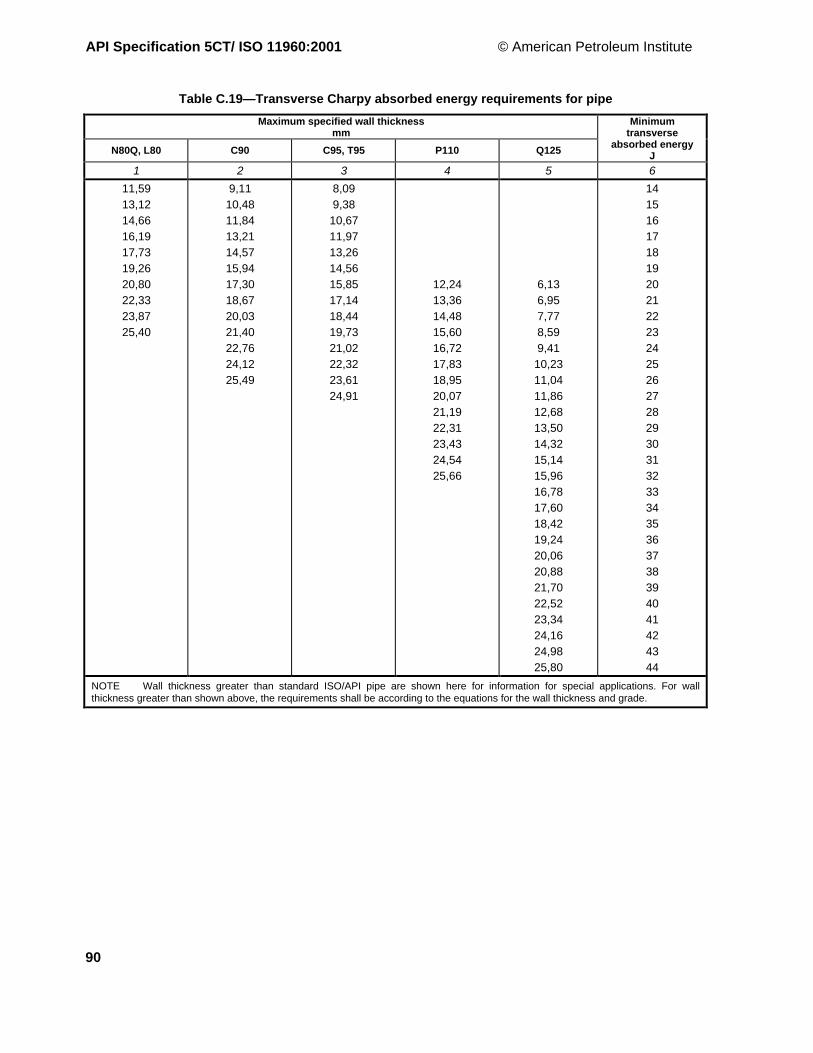
API Specification 5CT/ ISO 11960:2001 © American Petroleum Institute
90
Table C.19—Transverse Charpy absorbed energy requirements for pipe
Maximum specified wall thicknessmm
N80Q, L80 C90 C95, T95 P110 Q125
Minimumtransverse
absorbed energyJ
1 2 3 4 5 6
11,59
13,12
14,66
16,19
17,73
19,26
20,80
22,33
23,87
25,40
9,11
10,48
11,84
13,21
14,57
15,94
17,30
18,67
20,03
21,40
22,76
24,12
25,49
8,09
9,38
10,67
11,97
13,26
14,56
15,85
17,14
18,44
19,73
21,02
22,32
23,61
24,91
12,24
13,36
14,48
15,60
16,72
17,83
18,95
20,07
21,19
22,31
23,43
24,54
25,66
6,13
6,95
7,77
8,59
9,41
10,23
11,04
11,86
12,68
13,50
14,32
15,14
15,96
16,78
17,60
18,42
19,24
20,06
20,88
21,70
22,52
23,34
24,16
24,98
25,80
14
15
16
17
18
19
20
21
22
23
24
25
26
27
28
29
30
31
32
33
34
35
36
37
38
39
40
41
42
43
44
NOTE Wall thickness greater than standard ISO/API pipe are shown here for information for special applications. For wallthickness greater than shown above, the requirements shall be according to the equations for the wall thickness and grade.
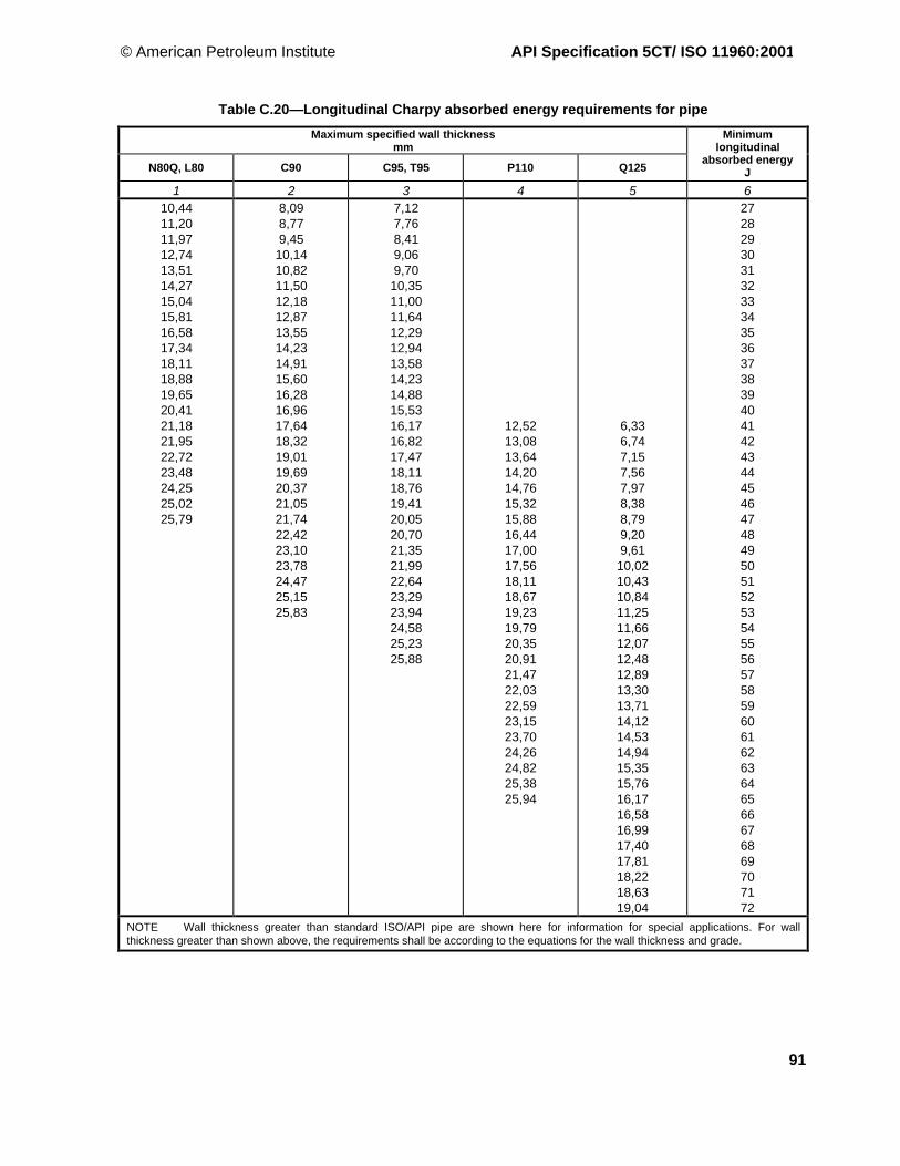
© American Petroleum Institute API Specification 5CT/ ISO 11960:2001
91
Table C.20—Longitudinal Charpy absorbed energy requirements for pipe
Maximum specified wall thicknessmm
N80Q, L80 C90 C95, T95 P110 Q125
Minimumlongitudinal
absorbed energyJ
1 2 3 4 5 610,4411,2011,9712,7413,5114,2715,0415,8116,5817,3418,1118,8819,6520,4121,1821,9522,7223,4824,2525,0225,79
8,098,779,4510,1410,8211,5012,1812,8713,5514,2314,9115,6016,2816,9617,6418,3219,0119,6920,3721,0521,7422,4223,1023,7824,4725,1525,83
7,127,768,419,069,7010,3511,0011,6412,2912,9413,5814,2314,8815,5316,1716,8217,4718,1118,7619,4120,0520,7021,3521,9922,6423,2923,9424,5825,2325,88
12,5213,0813,6414,2014,7615,3215,8816,4417,0017,5618,1118,6719,2319,7920,3520,9121,4722,0322,5923,1523,7024,2624,8225,3825,94
6,336,747,157,567,978,388,799,209,6110,0210,4310,8411,2511,6612,0712,4812,8913,3013,7114,1214,5314,9415,3515,7616,1716,5816,9917,4017,8118,2218,6319,04
27282930313233343536373839404142434445464748495051525354555657585960616263646566676869707172
NOTE Wall thickness greater than standard ISO/API pipe are shown here for information for special applications. For wallthickness greater than shown above, the requirements shall be according to the equations for the wall thickness and grade.

API Specification 5CT/ ISO 11960:2001 © American Petroleum Institute
92
Table C.21—Transverse impact specimen size required for pipe in quenched and tempered grades
Calculated wall thickness required to machinetransverse Charpy impact specimens
mmLabel 1
Full-size 3/4-size 1/2-size1 2 3 4
3-1/24
4-1/25
5-1/26-5/8
77-5/87-3/48-5/89-5/810-3/411-3/413-3/8
1618-5/8
20
20,5319,0918,0517,2616,6415,6215,3614,9914,9214,5114,1313,8013,5613,2412,8712,6012,49
18,0316,5915,5514,7614,1413,1212,8612,4912,4212,0111,6311,3011,0610,7410,3710,109,99
15,5314,0913,0512,2611,6410,6210,369,999,929,519,138,808,568,247,877,607,49
NOTE The wall thicknesses in columns 2, 3 and 4 that are in excess of the maximum ISO wall thicknesses are for informationonly. The above provides a 0,50 mm ID and a 0,50 mm OD machining allowance.
Table C.22—Longitudinal impact specimen size required for pipe in quenched and tempered grades
Calculated wall thickness required to machinelongitudinal Charpy impact specimens
mmLabel 1
Full-size 3/4-size 1/2-size
1 2 3 41.0501.3151.6601.9002.0632-3/82-7/83-1/2
44-1/2
55-1/26-5/8
77-5/87-3/48-5/89-5/810-3/411-3/413-3/8
1618-5/8
20
11,9711,7711,6011,5211,4811,4211,3411,2811,2511,2211,2011,1811,1511,1411,1311,1311,1111,1011,0911,0811,0711,0611,0511,05
9,479,279,109,028,988,928,848,788,758,728,708,688,658,648,638,638,618,608,598,588,578,568,558,55
6,976,776,606,526,486,426,346,286,256,226,206,186,156,146,136,136,116,106,096,086,076,066,056,05
NOTE The wall thicknesses in columns 2, 3 and 4 that are in excess of the maximum ISO wall thicknesses are for informationonly. The above provides a 0,50 mm ID and a 0,50 mm OD machining allowance.

© American Petroleum Institute API Specification 5CT/ ISO 11960:2001
93
Table C.23—Distance between plates for electric-weld flattening tests
GradeD/t
ratioMaximum distance between
platesmm
H40 ≥ 16
< 16
0,5 D
D × (0,830 − 0,020 6 D/t)
J55
&
K55
≥ 16
3,93 to 16
< 3,93
0,65 D
D × (0,980 − 0,020 6 D/t)
D × (1,104 − 0,051 8 D/t)
M65 All D × (1,074 − 0,019 4 D/t)
N80 a 9 to 28 D × (1,074 − 0,019 4 D/t)
L80
C95 a
P110 b
Q125 b
9 to 28
9 to 28
All
All
D × (1,074 − 0,019 4 D/t)
D × (1,080 − 0,017 8 D/t)
D × (1,086 − 0,016 3 D/t)
D × (1,092 − 0,014 0 D/t)
D is the specified outside diameter of pipe, in millimetres.
t is the specified wall thickness of the pipe, in millimetres.
a If the flattening test fails at 12 o'clock or 6 o'clock, the flattening shall continue until theremaining portion of the specimen fails at the 3 o'clock or 9 o'clock position. Prematurefailure at 12 o'clock or 6 o'clock shall not be considered basis for rejection.
b See A.5 (SR11). Flattening shall be at least 0,85 D.

API Specification 5CT/ ISO 11960:2001 © American Petroleum Institute
94
Table C.24—Dimensions and masses for round thread, buttress thread and extreme-line casing
Calculated mass cew, mass gain or loss due to end finishing d
kgLabels a Outsidediameter
Wallthick-ness
Insidediamet’r
Driftdiamet’r Plain
endRound thread Buttress thread Extreme-line
1 2D
mm
Nominallinearmass
T&C b, c
kg/m tmm
dmm mm
Wpekg/m Short Long Reg. OD SCC Stand’d Optional
1 2 3 4 5 6 7 8 9 10 11 12 13 144-1/24-1/24-1/24-1/24-1/2
9.5010.5011.6013.5015.10
114,30114,30114,30114,30114,30
14,1415,6317,2620,0922,47
5,215,696,357,378,56
103,88102,92101,6099,5697,18
100,7099,7498,4296,3894,00
14,0215,2416,9119,4422,32
1,911,721,54——
——
1,721,451,27
—2,272,091,811,45
—1,160,980,710,34
—————
————
5555555
11.5013.0015.0018.0021.4023.2024.10
127,00127,00127,00127,00127,00127,00127,00
17,1119,3522,3226,7931,8534,5335,86
5,596,437,529,19
11,1012,1412,70
115,82114,14111,96108,61104,80102,72101,60
112,64110,96108,78105,44101,6299,5498,42
16,7419,1222,1626,7031,7334,3935,80
2,452,181,91————
—2,632,361,911,341,040,88
—2,992,632,001,120,930,56
—1,100,730,,10−0,78−0,95−1,33
——
2,090,64———
———————
5-1/25-1/25-1/25-1/25-1/25-1/25-1/25-1/25-1/25-1/25-1/25-1/2
14.0015.5017.0020.0023.0026.8029.7032.6035.3038.0040.5043.10
139,70139,70139,70139,70139,70139,70139,70139,70139,70139,70139,70139,70
20,8323,0725,3029,7634,2339,8844,2048,5152,5356,5560,2764,14
6,206,987,729,17
10,5412,7014,2715,8817,4519,0520,6222,22
127,30125,74124,26121,36118,62114,30111,16107,94104,80101,6098,4695,25
124,12122,56121,08118,18115,44111,12107,98104,76101,6298,4295,2892,08
20,4122,8525,1329,5233,5739,7844,1448,4952,6156,6860,5564,38
2,452,182,00—————————
—2,632,452,001,45———————
—2,902,632,091,54———————
—0,950,680,14
−0,41———————
—2,632,180,640,00———————
—1,911,45
−0,09−0,73
———————
6-5/86-5/86-5/86-5/8
20.0024.0028.0032.00
168,28168,28168,28168,28
29,7635,7241,6747,62
7,328,94
10,5912,06
153,64150,40147,10144,16
150,46147,22143,92140,98
29,0635,1341,1846,46
4,994,35——
6,175,444,633,99
6,535,724,814,08
1,080,26
−0,64−1,37
—1,540,09
−0,64
—0,82
−0,64−1,36
777777777777777
17.0020.0023.0023.0026.0029.0032.0032.0035.0038.0042.7046.4050.1053.6057.10
177,80177,80177,80177,80177,80177,80177,80177,80177,80177,80177,80177,80177,80177,80177,80
25,3029,7634,2334,2338,6943,1647,6247,6252,0956,5563,5469,0574,5679,7784,97
5,876,918,058,059,19
10,3611,5111,5112,6513,7215,8817,4519,0520,6222,22
166,06163,98161,70161,70159,42157,08154,78154,78152,50150,36146,04142,90169,70136,56133,36
162,88160,80
158,75 e158,52156,24153,90
152,40 e151,60149,32147,18142,86139,72136,52133,38130,18
24,8929,1233,7033,7038,2142,7847,2047,2051,5255,5263,4169,0174,5879,9385,25
4,544,263,633,633,27——————————
——
4,724,724,263,632,992,992,542,00—————
——
4,994,994,353,723,083,082,541,91—————
——
0,730,730,09
−0,54−1,18−1,18−1,72−2,36
—————
——
2,722,721,270,27
−0,27−0,270,45
−0,09—————-
——
1,911,910,45
−0,54−1,09−1,09−0,82−1,36
—————
7-5/87-5/87-5/87-5/87-5/87-5/87-5/87-5/87-5/87-5/8
24.0026.4029.7033.7039.0042.8045.3047.1051.2055.30
193,68193,68193,68193,68193,68193,68193,68193,68193,68193,68
35,7239,2944,2050,1558,0463,6967,4170,0976,1982,30
7,628,339,52
10,9212,7014,2715,1115,8817,4519,05
178,44177,02174,64171,84168,28165,14163,46161,92158,78155,58
175,26173,84171,46168,66165,10161,96160,28158,74155,60152,40
34,9638,0843,2449,2256,6863,1466,5469,6375,8482,04
7,176,89————————
—8,627,897,176,175,455,014,61——
—9,348,537,716,625,175,014,19——
—2,822,001,180,10
−1,37−1,52−2,35
——
—2,901,180,00
−1,00—————
—1,810,09
−1,09−2,09
—————
7-3/47-3/4
46.1046.10
196,85196,85
68,6068,60
15,1115,11
166,63166,63
165,10 e163,45
67,7267,72
——
——
——
——
——
—-—
8-5/88-5/88-5/88-5/88-5/88-5/88-5/88-5/88-5/8
24.0028.0032.0032.0036.0040.0040.0044.0049.00
219,08219,08219,08219,08219,08219,08219,08219,08219,08
35,7241,6747,6247,6253,5759,5359,5365,4872,92
6,717,728,948,94
10,1611,4311,4312,7014,15
205,66203,64201,20201,20198,76196,22196,22193,68190,78
202,48200,46
198,02 e200,02195,58
193,68 e
193,04190,50187,60
35,1440,2446,3346,3352,3558,5358,5364,6471,51
10,7010,079,439,438,80————
——
12,5212,5211,6110,8010,809,898,89
——
12,7912,7911,8810,9810,9810,078,98
——
2,742,741,830,920,920,01
−1,08
——
5,995,993,451,811,810,73
−0,36
——
3,993,991,910,270,27
−0,82−1,91
See notes at end of table.

© American Petroleum Institute API Specification 5CT/ ISO 11960:2001
95
Table C.24 (continued)
Calculated mass cLabels a ew, mass gain or loss due to end finishing d
kgOutsidediameter
Wallthick-ness
Insidediamet’r
Driftdiamet’r Plain
endRound thread Buttress thread Extreme-line
1 2D
mm
Nominallinearmass
T&Cb, c
kg/m tmm
dmm mm
Wpekg/m Short Long Reg. OD SCC Stand’d Optional
1 2 3 4 5 6 7 8 9 10 11 12 13 149-5/89-5/89-5/89-5/89-5/89-5/89-5/89-5/89-5/89-5/89-5/89-5/89-5/89-5/8
32.3036.0040.0040.0043.5047.0053.5053.5058.4058.4059.4064.9070.3075.60
244,48244,48244,48244,48244,48244,48244,48244,48244,48244,48244,48244,48244,48244,48
48,0753,5759,5359,5364,7469,9479,6279,6286,9186.9188,4096,58
104,62112,51
7,928,94
10,0310,0311,0511,9913,8413,8415,1115,1115,4717,0718,6420,24
228,60226,60224,40224,40222,40220,50216,80216,80214,25214,25213,50210,30207,20204,00
224,66222,63
222,25 e220,45218,41216,54
215,90 e212,83
212,72 e210,29209,58206,38203,23200,02
46,2051,9357,9957,9963,6168,7578,7278,7285,4785,4787,3795,73
103,82111,93
11,0710,439,719,71——————————
—14,5113,6113,6112,7912,0710,6110,619,759,75————
—14,0613,1513,1512,3411,6110,1610,169,139,13————
—2,942,032,031,220,49
−0,96−0,96−2,00−2,00
————
——
4,814,812,451,00
−0,54−0,54
——————
——
3,273,270,91
−0,54−2,09−2,09
——————
10-3/410-3/410-3/410-3/410-3/410-3/410-3/410-3/410-3/410-3/410-3/410-3/4
32.7540.5045.5045.5051.0055.5055.5060.7065.7073.2079.2085.30
273,05273,05273,05273,05273,05273,05273,05273,05273,05273,05273,05273,05
48,7460,2767,7167,7175,9082,5982,5990,3397,77
108,93117,86126,94
7,098,89
10,1610,1611,4312,5712,5713,8415,1117,0718,6420,24
258,90255,30252,70252,70250,20247,90247,90245,40242,80238,90235,80232,60
254,91251,31
250,82 e248,77246,23
244,48 e243,94241,40238,86234,95231,80228,60
46,5057,9165,8765,8773,7580,7580,7588,4796,12
107,76116,95126,19
13,1511,9711,0711,0710,259,439,438,537,62———
————————————
—15,6014,4214,4213,3412,2512,2511,079,98———
—3,272,092,091,00
−0,09−0,09
—————
——
9,629,628,357,177,175,90————
————————————
11-3/411-3/411-3/411-3/411-3/411-3/411-3/411-3/411-3/4
42.0042.0047.0054.0060.0060.0065.0065.0071.00
298,45298,45298,45298,45298,45298,45298,45298,45298,45
62,5062,5069,9480,3689,2989,2996,7396,73
105,66
8,468,469,53
11,0512,4212,4213,5613,5614,78
281,50281,50279,40276,40273,60273,60271,30271,30268,90
279,40 e
277,50275,44272,39
269,88 e
269,65269,88 e267,36264,92
62,5662,5669,9478,3287,6187,6195,2795,27
103,40
13,4313,4312,5211,3410,2510,25
———
—————————
——
16,2414,7013,4313,43
———
—————————
—————————
—————————
13-3/813-3/813-3/813-3/813-3/813-3/8
48.0054.5061.0068.0072.0072.00
339,73339,73339,73339,73339,73339,73
71,4381,1090,78
101,19107,15107,15
8,389,65
10,9212,1913,0613,06
323,00320,40317,90315,30313,60313,60
319,00316,46313,92311,38
311,15 e309,65
68,4878,5588,5598,46
105,21105,21
15,0613,9712,8811,7010,9810,98
——————
—18,2316,6915,2414,3314,33
——————
——————
——————
16161616
65.0075.0084.00
109.00
406,40406,40406,40406,40
96,73111,61125,01162,21
9,5311,1312,5716,66
387,40384,10381,30373,10
382,57379,37376,48368,30
96,73108,49122,09160,13
19,3217,3315,51
—
————
—20,6817,96
—
————
————
————
18-5/8 87.50 473,10 130,21 11,05 451,00 446,20 125,91 33,38 — 39,19 — — —202020
94.00106.50133.00
508,00508,00508,00
139,89158,49197,93
11,1312,7016,13
485,70482,60475,70
480,97477,82470,97
136,38155,13195,66
21,3218,8713,61
27,7624,8618,42
24,8621,9515,97
———
———
———
See also Figures D.1, D.2, D.3 and D.8.a Labels are for information and assistance in ordering.b Nominal linear masses, threaded and coupled (Col. 4) are shown for information only.c The densities of martensitic chromium steels (L80 Types 9Cr and 13Cr) are less than those of carbon steels. The masses shownare therefore not accurate for martensitic chromium steels. A mass correction factor of 0,989 may be used.d Mass gain or loss due to end finishing. See 8.5.e Drift diameter for most common bit size. This drift diameter shall be specified on the purchase agreement and marked on the pipe.See 8.10 for drift requirements.

API Specification 5CT/ ISO 11960:2001 © American Petroleum Institute
96
Table C.25—Dimensions and masses for non-upset, external upset and integral joint tubing
Nominal linear masses b, c Calculated mass cLabels a ew, mass gain or loss due to end
finishing d , kg1 2 External upset e
NUT&C
EUT&C
IJ
Outsidedia.
Dmm
Non-upsetT&C
kg/m
ExtupsetT&C
kg/m
Integraljoint
kg/m
Wallthick-ness
tmm
Insidedia.
dmm
Plainend
Wpe
kg/m
Non-upset Regular Special
clear
Integraljoint
1 2 3 4 5 6 7 8 9 10 11 12 13 14 151.0501.050
1.141.48
1.201.54
——
26,6726,67
1,702,20
1,792,29
——
2,873,91
20,9318,85
1,682,19
0,09—
0,640,60
——
——
1.3151.315
1.702.19
1.802.24
1.72—
33,4033,40
2,533,26
2,683,33
2,56—
3,384,55
26,6424,30
2,503,24
0,18—
0,640,61
——
0,09—
1.6601.6601.660
2.092.303.03
—2.403.07
2.102.33—
42,1642,1642,16
—3,424,51
—3,574,57
3,133,47—
3,183,564,85
35,8135,0432,46
3,063,394,46
—0,36—
—0,730,68
———
0,090,09—
1.9001.9001.9001.9001.900
2.402.753.654.425.15
—2.903.73——
2.402.76———
48,2648,2648,2648,2648,26
—4,095,436,587,66
—4,325,55——
3,574,11———
3,183,685,086,357,62
41,9040,9038,1035,5633,02
3,54,4,055,416,567,64
—0,27———
—0,910,92——
—————
0,090,09———
2.0632.063
3.244.50
——
3.25—
52,4052,40
——
——
4,84—
3,965,72
44,4840,96
4,736,58
——
——
——
0,09—
2-3/82-3/82-3/82-3/82-3/8
4.004.605.806.607.35
—4.705.95—
7.45
—————
60,3260,3260,3260,3260,32
5,956,858,639,82
10,94
—6,998,85—
11,09
—————
4,244,836,457,498,53
51,8450,6647,4245,3443,26
5,876,618,579,76
10,89
0,730,730,64——
—1,811,63——
—1,341,16——
—————
2-7/82-7/82-7/82-7/82-7/82-7/8
6.407.808.609.35
10.5011.50
6.507.908.709.45——
——————
73,0273,0273,0273,0273,0273,02
9,5211,6112,8013,9115,6317,11
9,6711,7612,9514,06
——
——————
5,517,017,828,649,96
11,18
62,0059,0057,3855,7553,1050,66
9,1711,4112,5713,7215,4917,05
1,451,271,18———
2,542,632,27———
1,711,781,43———
——————
3-1/23-1/23-1/23-1/23-1/23-1/23-1/2
7.709.20
10.2012.7014.3015.5017.00
—9.30—
12.95———
———————
88,9088,9088,9088,9088,9088,9088,90
11,4613,6915,1818,9021,2823,0725,30
—13,84
—19,27
———
———————
5,496,457,349,52
10,9212,0913,46
77,9276,0074,2269,8667,0664,7261,98
11,2913,1214,7618,6421,0022,9025,04
2,452,272,181,81———
—4,17—
3,72———
—2,45—
2,00———
———————
444444
9.5010.7013.2016.1018.9022.20
—11.00
————
——————
101,60101,60101,60101,60101,60101,60
14,14—
19,6423,9628,1333,04
—16,37
————
——————
5,746,658,38
10,5412,7015,49
90,1288,3084,8480,5276,2070,62
13,5715,5719,2723,6727,8432,89
2,81—————
—4,81————
——————
——————
4-1/24-1/24-1/24-1/24-1/24-1/24-1/2
12.6015.2017.0018.9021.5023.7026.10
12.75——————
———————
114,30114,30114,30114,30114,30114,30114,30
18,7522,6225,3028,1332,0035,2738,84
18,97——————
———————
6,888,569,65
10,9212,7014,2216,00
100,5497,1895,0092,4688,9085,8682,30
18,2322,3224,9027,8431,8235,1038,79
2,72——————
———————
———————
———————
See also Figures D.4, D.5 and D.7.a Labels are for information and assistance in ordering.b Nominal linear masses, threaded and coupled (Col. 6,7 and 8) are shown for information only.c The densities of martensitic chromium (L80 Types 9Cr and 13Cr) are different from carbon steels. The masses shown are therefore notaccurate for martensitic chromium steels. A mass correction factor of 0,989 may be used.d Mass gain or loss due to end finishing. See 8.5.e The length of the upset may alter the mass gain or loss due to end finishing.

© American Petroleum Institute API Specification 5CT/ ISO 11960:2001
97
Table C.26—Extreme-line casing upset end dimensions and masses
Finished pin-and-box dimensions a
LabelsOutsidediameter
Nominallinearmassupsetand
threaded
Pin-and-box outsidediameter (turned)
+0.51−0.25
Pin insidediameter(bored)
± 0,38
Box insidediameter(bored)
+0.760
Pin-and-box made-up(power-tight) b
Driftdia’r for
finishedupset
member
Driftdiameterfor fulllengthdrifting
min.mm kg/m mm mm mm mm mm
Standard OptionalStandard
andoptional
Standardand
optional
Outside diameter,
+0.51−0.25
mmInside diameter,
+0.25−0.13
Standardand
optional
Standardand
optional1 2 D M M B D Standard c Optional c Standard and
optional1 2 3 4 5 6 7 8 9 10 11 12 13
5
5
15.00
18.00
127,00
127,00
22,32
26,79
136,14
136,14
—
—
106,88
106,88
107,57
107,57
136,14
136,14
—
—
106,63
106,63
106,25
106,25
105,44
105,44
5-1/2
5-1/2
5-1/2
5-1/2
15.50
17.00
20.00
23.00
139,70
139,70
139,70
139,70
23,07
25,30
29,76
34,23
148,84
148,84
148,84
148,84
146,81
146,81
146,81
146,81
120,55
119,66
119,66
117,32
121,23
120,35
120,35
118,03
148,84
148,84
148,84
148,84
146,81
146,81
146,81
146,81
120,29
119,41
119,41
117,09
119,91
119,02
119,02
116,71
118,19
118,19
118,19
115,44
6-5/8
6-5/8
6-5/8
24.00
28.00
32.00
168,28
168,28
168,28
35,72
41,67
47,62
177,80
177,80
177,80
176,02
176,02
176,02
147,12
145,82
142,85
147,78
146,51
143,56
177,80
177,80
177,80
176,02
176,02
176,02
146,84
145,57
142,62
146,46
145,19
142,24
145,54
143,92
140,97
7
7
7
7
7
7
23.00
26.00
29.00
32.00
35.00
38.00
177,80
177,80
177,80
177,80
177,80
177,80
34,23
38,69
43,16
47,62
52,09
56,55
187,71
187,71
187,71
187,71
191,26
191,26
185,67
185,67
185,67
185,67
187,71
187,71
157,02
157,02
155,80
153,47
151,10
149,07
157,68
157,68
156,46
154,15
151,82
149,78
187,71
187,71
187,71
187,71
191,26
191,26
185,67
185,67
185,67
185,67
187,71
187,71
156,74
156,74
155,52
153,21
150,88
148,84
156,36
156,36
155,14
152,83
150,50
148,46
156,24
156,24
153,90
151,61
149,33
147,19
7-5/8
7-5/8
7-5/8
7-5/8
26.40
29.70
33.70
39.00
193,68
193,68
193,68
193,68
39,29
44,20
50,15
58,04
203,45
203,45
203,45
203,45
201,17
201,17
201,17
201,17
172,26
172,26
170,59
167,00
172,90
172,90
171,25
167,69
203,45
203,45
203,45
203,45
201,17
201,17
201,17
201,17
171,96
171,96
170,31
166,75
171,58
171,58
169,93
166,37
171,45
171,45
168,66
165,10
8-5/8
8-5/8
8-5/8
8-5/8
8-5/8
32.00
36.00
40.00
44.00
49.00
219,08
219,08
219,08
219,08
219,08
47,62
53,57
59,53
65,48
72,92
231,65
231,65
231,65
231,65
231,65
229,36
229,36
229,36
229,36
229,36
196,52
196,52
194,92
192,40
189,48
197,15
197,16
195,58
193,09
190,20
231,65
231,65
231,65
231,65
231,65
229,36
229,36
229,36
229,36
229,36
196,22
196,22
194,64
192,15
189,26
195,83
195,83
194,26
191,77
188,87
195,58
195,58
193,04
190,50
187,60
9-5/8
9-5/8
9-5/8
9-5/8
40.00
43.50
47.00
53.50
244,48
244,48
244,48
244,48
59,53
64,73
69,94
79,62
256,54
256,54
256,54
256,54
254,51
254,51
254,51
254,51
220,40
220,40
219,28
215,52
221,03
221,03
219,91
216,20
256,54
256,54
256,54
256,54
254,51
254,51
254,51
254,51
220,09
220,09
218,97
215,27
219,71
219,71
218,59
214,88
218,41
218,41
216,54
212,83
10_
10_
10_10_
45.50
51.00
55.50
60.70
273,05
273,05
273,05
273,05
67,71
75,90
82,59
90,33
291,08
291,08
291,08
291,08
—
—
—
—
249,66
247,12
244,83
242,29
250,29
247,75
245,47
242,93
291,08
291,08
291,08
291,08
—
—
—
—
249,40
246,86
244,58
242,04
249,02
246,48
244,20
241,66
248,77
246,23
243,94
241,40
See also Table C.24 and Figure D.8.a Due to the nature of extreme-line casing, certain dimensional symbols and nomenclature differ from those for similar details for other pipecovered by this International Standard.b Shown for reference.c Made-up joint D is the same as the outside diameter dimension M.

API Specification 5CT/ ISO 11960:2001 © American Petroleum Institute
98
Table C.27—External-upset tubing—Upset end dimensions and masses for Groups 1, 2 and 3
UpsetLabels a Outside diameter Nominal linear
massthreaded and
coupled b
Outside diameter c+1,59
0
Length fromend of pipe to
start of taper d, e
+25,40
Length fromend of pipe toend of taper e
Length fromend of pipe tostart of pipe
body emax.
mm kg/m mm mm mm mm1 2 D D4 Leu La Lb1 2 3 4 5 6 7 8
1.0501.0501.3151.3151.6601.6601.9001.900
1.201.541.802.242.403.072.903.73
26,6726,6733,4033,4042,1642,1648,2648,26
1,792,292,683,333,574,574,325,55
33,4033,4037,3137,3146,0246,0253,1953,19
60,3260,3263,5063,5066,6866,6868,2668,26
————————
————————
2-3/82-3/82-3/8
4.705.957.45
60,3260,3260,32
6,998,85
11,09
65,8965,8965,89
101,60101,60101,60
152,40152,40152,40
254,00254,00254,00
2-7/82-7/82-7/82-7/8
6.507.908.709,45
73,0273,0273,0273,02
9,6711,7612,9514,06
78,5978,5978,5978,59
107,95107,95107,95107,95
158,75158,75158,75158,75
260,35260,35260,35260,35
3-1/23-1/2
9.3012.95
88,9088,90
13,8419,27
95,2595,25
114,30114,30
165,10165,10
266,70266,70
4 11.00 101,60 16,37 107,95 114,30 165,10 266,704-1/2 12.75 114,30 18,97 120,65 120,65 171,45 273,05
See also Figures D.5 and D.6.
a Labels are for information and assistance in ordering.b The densities of martensitic chromium steels (L80 9Cr and 13Cr) are different from carbon steels. The masses shown are
therefore not accurate for chromium steels. A mass correction factor of 0,989 may be used.c T he m inimu m o ut sid e dia me t er o f u pse t D4 is limite d b y the m inimu m len g th o f f ull-cre st th r ea ds. See ISO 1 04 22 or API Sp e c 5B.
d For pup-joints only, the length tolerance on Leu is 101,625,4 mm. The length on Lb may be 101,6 mm longer than specified.
e For extended-length upsets on external upset tubing, add 25,4 mm to the dimensions in columns 5, 6 and 7.
Table C.28—Integral joint tubing—Upset end dimensions and masses for Groups 1, 2
Upset dimensionsPin Box
Labels Outsidedia.
Nominallinear
mass a
T&C
Outsidedia. b+1,59
0
Insidedia. c+0,38
0
Length
min.
Lengthof taper
min.
Outsidediameter
+ 0.13 - 0.64
Length
min.
Length oftaper
Diameterof recess
Width offacemin.
mm kg/m mm mm mm mm mm mm mm mm mm1 2 D D4 diu Liu miu Wb Leu meu Q b1 2 3 4 5 6 7 8 9 10 11 12 13
1.315 1.72 33,40 2,56 — 24,64 34,92 6,35 39,37 44,45 25,40 35,00 0,791.6601.660
2.102.33
42,1642,16
3,133,47
——
33,0533,05
38,1038,10
6,356,35
47,7547,75
47,6247,62
25,4025,40
43,7643,76
0,790,79
1.9001.900
2.402.76
48,2648,26
3,574,11
——
38,8938,89
41,2841,28
6,356,35
53,5953,59
50,8050,80
25,4025,40
49,8649,86
0,790,79
2.063 3.25 52,40 4,84 53,19 42,47 42,86 6,35 59,06 53,98 25,40 54,76 0,79See also Figure D.7.a Nominal linear masses, upset and threaded, are shown for information only.b The minimum outside diameter D4 is limited by the minimum length of full-crest threads. See ISO 10422 or API Spec 5B.c The minimum diameter diu is limited by the drift test.

© American Petroleum Institute API Specification 5CT/ ISO 11960:2001
99
Table C.29—Plain-end liners—Dimensions and masses for Grade J55
Labels Outside diameter
D
Plain-endlinear mass
Wallthickness
t
Insidediameter
d1 2 mm kg/m mm mm1 2 3 4 5 6
3-1/24
4-1/25
5-1/26-5/8
9.9211.3513.0517.9519.8327.67
88,90101,60114,30127,00139,70168,28
14,7616,8919,4426,7029,5241,18
7,347,267,379,199,1710,59
74,2287,0899,56108,62121,36147,10
Table C.30—Range lengths
Dimensions in metres
Range 1 Range 2 Range 3
CASING AND LINERS
Total range length, inclusive
Range length for 95 % or more of carload: a
Permissible variation, max.
Permissible length, min.
4,88 to 7,62
1,83
5,49
7,62 to 10,36
1,52
8,53
10,36 to 14,63
1,83
10,97
TUBING AND CASING USED AS TUBING
Total range length, inclusive b
Range length for 100 % of carload: a
Permissible variation, max
6,10 to 7,32
0,61
8,53 to 9,75
0,61
11,58 to 12,80 c
0,61
PUP-JOINTS Lengths 0,61; 0,91; 1,22; 1,83 ; 2,44 ; 3,05 and 3,66 d
Tolerance ± 0,076a Carload tolerances shall not apply to order items of less than 18 144 kg of pipe. For any carload of 18 144 kg or more of pipe thatis shipped to the final destination without transfer or removal from the car, the tolerance shall apply to each car. For any order itemconsisting of more than 18 144 kg of pipe that is shipped from the manufacturer's facility by rail, but not to the final destination, thecarload tolerance shall apply to the overall quantity of pipe shipped on the order item, but not to the individual carloads.b By agreement between purchaser and manufacturer the total range length for Range 1 tubing may be 6,10 m to 8,53 m.c By agreement between manufacturer and purchaser the maximum length may be increased to 13,72 m.d 0,61 m pup-joints may be furnished up to 0,91 m long by agreement between purchaser and manufacturer, and lengths other thanthose listed may be furnished by agreement between purchaser and manufacturer.
Table C.31—Standard drift size
Dimensions in millimetres
Product and Label 1 Standard drift mandrel sizemin.
Length Diameter
Casing a and liners< 9-5/8
≥ 9-5/8 to ≤ 13-3/8> 13-3/8
152305305
d – 3,18d – 3,97d – 4,76
Tubing b
≤ 2-7/8> 2-7/8
1 0671 067
d – 2,38d – 3,18
a The minimum diameter of the drift mandrel for extreme-line casing shall be as shown in col.12and 13, Table C.26.b Integral-joint tubing shall be tested before upsetting with a drift mandrel as shown, and shall also bedrift tested at the pin end, after upsetting, with a cylindrical drift mandrel 1 067 mm in length anddiu – 0,38 mm in diameter (see Table C.28, Col. 6 for diu).

API Specification 5CT/ ISO 11960:2001 © American Petroleum Institute
100
Table C.32—Alternative drift size
Labels Outside diameterD
Product linear mass Alternative drift mandrel sizemin.mm
1 2 mm kg/m Length Diameter
1 2 3 4 5 6
7
7
7-3/4
8-5/8
8-5/8
9-5/8
9-5/8
9-5/8
10-3/4
10-3/4
11-3/4
11-3/4
11-3/4
13-3/8
23.00
32.00
46.10
32.00
40.00
40.00
53.50
58.40
45.50
55.50
42.00
60.00
65.00
72.00
177,80
177,80
196,85
219,08
219,08
244,48
244,48
244,48
273,05
273,05
298,45
298,45
298,45
339,72
34,23
47,62
68,60
47,62
59,53
59,53
79,62
86,91
67,71
82,59
62,50
89,29
96,73
107,15
152
152
152
152
152
305
305
305
305
305
305
305
305
305
158,75
152,40
165,10
200,03
193,68
222,25
215,90
212,72
250,82
244,48
279,40
269,88
269,88
311,15
Table C.33—Maximum permissible depth of linear imperfections
Depth as % of specified wall thicknessGrade External Internal
H40 – J55 – K55 – M65 – N80 – N80QL80 – C95 – P110 to A.9 (SR16)
12,5 % 12,5 %
C90 – T95 – P110 – Q125 5 % 5 %
P110 to A.9 (SR16)
and A.2 (SR2)5 % 5 %

© American Petroleum Institute API Specification 5CT/ ISO 11960:2001
101
Table C.34—Upset products—Maximum permissible depth of imperfections
Surface Depth Measurement notes
1 2 3 4
A. Extreme-line casing, integral joint and external upset tubing (see Figures D.5, D.7 and D.8)
A.1 All surfaces of upset and upsetrun-out interval, except as statedbelow
12,5 % t
12,5 % t
5 % t
Percentage of specified pipe body wall thickness t; fornon-linear imperfections; for all groups of pipe
Percentage of specified pipe body wall thickness t; for linearimperfections; for Group 1 and Group 2 (except C90 and T95) pipe
Percentage of specified pipe body wall thickness t; for linearimperfections; for Group 3, Group 4 and Grades C90 and T95 pipe
A.2 The minimum wall thickness in the upset run-out interval, and the maximum combined effect of coincident internal and externalimperfections in all areas, shall not total less than 87,5 % of the specified wall thickness.
B. Extreme-line casing (see Figure D.8)
B.1.
B.2
Box end external surface
Pin end internal surface
0,25 mm
0,25 mm
0,38 mm
For Label-1: 7-5/8 and smaller sizes. From end of pipe toa plane 120,6 mm from the end.
For Label-1: Larger than 7-5/8. From end of pipe toa plane 165,1 mm from the end.
From end of pipe to plane of external shoulder (bored)B.3 All machined surfaces of the box shall be free of seams, laps and cracks. The pin-and-box shall be free of any imperfections whichbreak the continuity of the threads or seals.
C. Integral joint tubing (see Figure D.7)
C.1
C.2
Box end external surface
Pin end internal surface
0,25 mm
0,38 mm
From end of pipe to a plane at a distance equal to thespecified minimum dimension Leu (Figure D.7) from end of pipe.
From end of pipe to a plane at a distance equal to thespecified minimum dimension Liu (Figure D.7) from end of pipe.
For Grades C90 and T95, the maximum permissible depth forlinear imperfections shall be 5 % of the specified pipe body wallthickness.
C.3 Upset underfills in the upset run-out intervals shall not be considered a defect unless the remaining wall thickness (at the upsetunderfill) is less than 87,5 % of the specified pipe body wall thickness.

API Specification 5CT/ ISO 11960:2001 © American Petroleum Institute
102
Table C.35—Round-thread casing coupling dimensions, masses and tolerances
Size a Minimum lengthmm
Masskg
Label-1Outside diameter
D
Outside diameter
W
Short
NL
Long
NL
Diameter ofrecess
Q b
Width of bearingface
bShort Long
mm mm mm mm
1 2 3 4 5 6 7 8 9
4-1/2
5
5-1/2
6-5/8
7
7-5/8
8-5/8
9-5/8
10-3/4
11-3/4
13-3/8
16
18-5/8
20
114,30
127,00
139,70
168,28
177,80
193,70
219,08
244,48
273,05
298,45
339,72
406,40
473,08
508,00
127,00
141,30
153,67
187,71
194,46
215,90
244,48
269,88
298,45
323,85
365,12
431,80
508,00
533,40
158,75
165,10
171,45
184,15
184,15
190,50
196,85
196,85
203,20
203,20
203,20
228,60
228,60
228,60
177,80
196,85
203,20
222,25
228,60
234,95
254,00
266,70
—
—
—
—
—
292,10
116,68
129,38
142,08
170,66
180,18
197,64
223,04
248,44
277,02
302,42
343,69
411,96
478,63
513,56
3,97
4,76
3,18
6,35
4,76
5,56
6,35
6,35
6,35
6,35
5,56
5,56
5,56
5,56
3,62
4,66
5,23
9,12
8,39
12,30
16,23
18,03
20,78
22,64
25,66
34,91
54.01
43,42
4,15
5,75
6,42
11,34
10,83
15,63
21,67
25,45
—
—
—
—
—
57,04
See also Figures D.1 and D.2.Tolerance on outside diameter W, ±1 % but not greater than ± 3,18 mm—Groups 1, 2 and 3.
Tolerance on outside diameter W, ±1 % but not greater than +3,18−1,59—Group 4.
a The size designation for the coupling is the same as the size designation for the pipe on which the coupling is used.
b Tolerance on diameter of recess, Q, for all groups is +0,79
0

© American Petroleum Institute API Specification 5CT/ ISO 11960:2001
103
Table C.36—Buttress thread casing coupling dimensions, masses and tolerances
Size a Outside diameterMass
kg
Label-1Outsidediameter
D
mm
Regular
W
mm
Specialclearance
Wc
mm
Minimumlength
NL
mm
Diameter ofcounterbore
Q
mm
Width ofbearing face
b
mm
Regular Specialclearance
1 2 3 4 5 6 7 8 9
4-1/2
5
5-1/2
6-5/8
7
7-5/8
8-5/8
9-5/8
10-3/4
11-3/4
13-3/8
16
18-5/8
20
114,30
127,00
139,70
168,28
177,80
193,68
219,08
244,48
273,05
298,45
339,72
406,40
473,08
508,00
127,00
141,30
153,67
187,71
194,46
215,90
244,48
269,88
298,45
323,85
365,12
431,80
508,00
533,40
123,82
136,52
149,22
177,80
187,32
206,38
231,78
257,18
285,75
—
—
—
—
—
225,42
231,78
234,95
244,48
254,00
263,52
269,88
269,88
269,88
269,88
269,88
269,88
269,88
269,88
117,86
130,56
143,26
171,83
181,36
197,23
222,63
248,03
276,61
302,01
343,28
410,31
476,99
511,91
3,18
3,97
3,97
6,35
5,56
7,94
9,52
9,52
9,52
9,52
9,52
9,52
9,52
9,52
4,55
5,85
6,36
11,01
10,54
15,82
20,86
23,16
25,74
28,03
31,77
40,28
62,68
50,10
3,48
4,00
4,47
5,65
6,28
9,29
10,80
12,02
13,39
—
—
—
—
—
See also Figure D.3.Tolerance on outside diameter W, ±1 % but not greater than ± 3,18 mm—Groups 1, 2 and 3.
Tolerance on outside diameter W, ±1 % but not greater than +3,18−1,59—Group 4.
a The size designation for the coupling is the same as the size designation for the pipe on which the coupling is used.
Table C.37—Non-upset tubing coupling dimensions, masses and tolerances
Size a
Label 1Outsidediameter
Outsidediameter
Minimumlength
Diameterofrecess
Width ofbearing
face
Maximum bearingface diameter,special bevel
Mass
D W NL Q b Bf
mm mm mm mm mm mm kg
1 2 3 4 5 6 7 8
1.050
1.315
1.660
1.900
2-3/8
2-7/8
3-1/2
4
4-1/2
26,67
33,40
42,16
48,26
60,32
73,02
88,90
101,60
114,30
33,35
42,16
52,17
55,88
73,02
88,90
107,95
120,65
132,08
80,96
82,55
88,90
95,25
107,95
130,18
142,88
146,05
155,58
28,27
35,00
43,76
49,86
61,93
74,63
90,50
103,20
115,90
1,59
2,38
3,18
1,59
4,76
4,76
4,76
4,76
4,76
30,00
37,80
47,17
52,07
66,68
80,98
98,42
111,12
123,19
0,23
0,38
0,59
0,56
1,28
2,34
3,71
4,35
4,89
See also Figure D.4.
Tolerance on outside diameter W, ±1 %.a The size designation for the coupling is the same as the size designation for the pipe on which the coupling is used.

API Specification 5CT/ ISO 11960:2001 © American Petroleum Institute
104
Table C.38—External-upset tubing coupling dimensions, masses and tolerances
Size a Outside diameterMaximum bearing face
diameterBf
Masskg
Label 1Outsidediameter
Regular &specialbevel
Specialclearance
Minimumlength
Diameterof
recess
Width ofbearing
face,regular Special
bevelSpecial
clearance Regular Specialclearance
D W WC NL Q
mm mm mm mm mm mm mm mm
1 2 3 4 5 6 7 8 9 10 11
1.050
1.315
1.660
1.900
2-3/8
2-7/8
3-1/2
4
4-1/2
26,67
33,40
42,16
48,26
60,32
73,02
88,90
101,60
114,30
42,16
48,26
55,88
63,50
77,80
93,17
114,30
127,00
141,30
—
—
—
—
73,91
87,88
106,17
—
—
82,55
88,90
95,25
98,42
123,82
133,35
146,05
152,40
158,75
35,00
38,89
47,63
54,76
67,46
80,16
96,85
109,55
122,25
2,38
2,38
3,18
3,18
3,97
5,56
6,35
6,35
6,35
37,80
42,77
50,95
58,34
71,83
85,88
104,78
117,48
130,96
—
—
—
—
69,90
83,24
100,71
—
—
0,38
0,57
0,68
0,84
1,55
2,40
4,10
4,82
6,05
—
—
—
—
1,07
1,55
2,38
—
—
See also Figure D.5.Tolerance on outside diameter W, ± 1 %.
Tolerance on outside diameter WC, ± 0,38 mm.
a The size designation for the coupling is the same as the size designation for the pipe on which the coupling is used.
Table C.39—Permissible depth of coupling external imperfections
Group 1Group 2 (except C90 and T95)
Group 3
Group 2 (C90 and T95)Group 4
Coupling for pipe size Pits and round-bottomgouges
Grip marks andsharp-bottom gouges
Pits, round-bottom gouges,sharp-bottom gouges, grip
marks
1 2 3 4 5
< 3-1/2 0,76 0,64 0,76
≥ 3-1/2 to ≤ 4-1/2 1,14 0,76 0,89
Tubing
< 6-5/8 0,89 0,76 0,76
Casing a ≥ 6-5/8 to ≤ 7-5/8 1,14 1,02 0,89
> 7-5/8 1,52 1,02 0,89a Includes casing used as tubing.
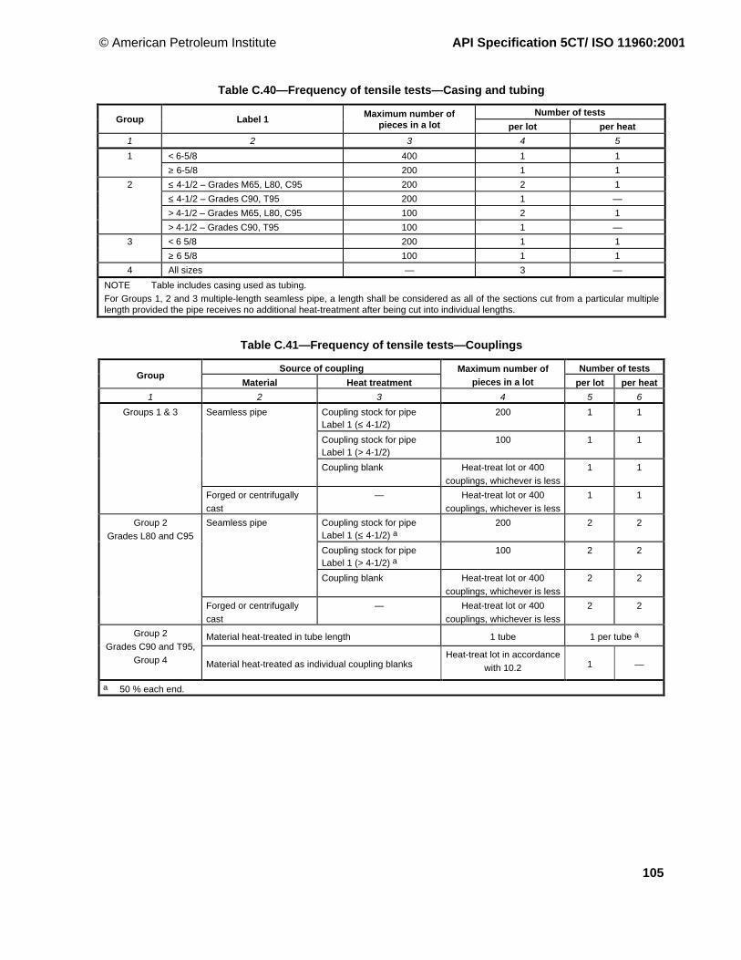
© American Petroleum Institute API Specification 5CT/ ISO 11960:2001
105
Table C.40—Frequency of tensile tests—Casing and tubing
Number of testsGroup Label 1 Maximum number of
pieces in a lot per lot per heat
1 2 3 4 5
< 6-5/8 400 1 11
≥ 6-5/8 200 1 1
≤ 4-1/2 – Grades M65, L80, C95 200 2 1
≤ 4-1/2 – Grades C90, T95 200 1 —
> 4-1/2 – Grades M65, L80, C95 100 2 1
2
> 4-1/2 – Grades C90, T95 100 1 —
< 6 5/8 200 1 13
≥ 6 5/8 100 1 1
4 All sizes — 3 —
NOTE Table includes casing used as tubing.
For Groups 1, 2 and 3 multiple-length seamless pipe, a length shall be considered as all of the sections cut from a particular multiplelength provided the pipe receives no additional heat-treatment after being cut into individual lengths.
Table C.41—Frequency of tensile tests—Couplings
Source of coupling Number of testsGroup
Material Heat treatment
Maximum number ofpieces in a lot per lot per heat
1 2 3 4 5 6
Coupling stock for pipeLabel 1 (≤ 4-1/2)
200 1 1
Coupling stock for pipeLabel 1 (> 4-1/2)
100 1 1
Seamless pipe
Coupling blank Heat-treat lot or 400
couplings, whichever is less
1 1
Groups 1 & 3
Forged or centrifugally
cast
— Heat-treat lot or 400
couplings, whichever is less
1 1
Coupling stock for pipeLabel 1 (≤ 4-1/2) a
200 2 2
Coupling stock for pipeLabel 1 (> 4-1/2) a
100 2 2
Seamless pipe
Coupling blank Heat-treat lot or 400
couplings, whichever is less
2 2
Group 2
Grades L80 and C95
Forged or centrifugally
cast
— Heat-treat lot or 400
couplings, whichever is less
2 2
Material heat-treated in tube length 1 tube 1 per tube aGroup 2
Grades C90 and T95,
Group 4 Material heat-treated as individual coupling blanksHeat-treat lot in accordance
with 10.2 1 —
a 50 % each end.

API Specification 5CT/ ISO 11960:2001 © American Petroleum Institute
106
Table C.42—Frequency of tensile tests—Pup-joints and accessories
Source of pup-joints and accessories Number of testsGroup
Material Heat treatmentMaximum number of
pieces in a lot per lot per heat
1 2 3 4 5 6
Heat-treated separatelyfrom casing and tubing
— 1 1
Casing a or tubing Batch heat treatment 100 pup-joints or 400accessories
1 1
Continuous heat treatment In accordance with 10.2 1 1
≤ Label 1: 4-1/2:
200 tubes or bars
1 1
Groups 1 & 3
Thick wall tube or barstock
—
> Label 1: 4-1/2:
100 tubes or bars
1 1
Heat-treated separatelyfrom casing and tubing
— 2 2
Casing a or tubing Batch heat treatment 100 pup-joints or 400accessories
2 2
Continuous heat treatment In accordance with 10.2 2 2
≤ Label 1: 4-1/2:
200 tubes or bars
2 2
Group 2
Grades L80 & C95
Thick wall tube or barstock
—
> Label 1: 4-1/2:
100 tubes or bars
2 2
Group 2
Grades C90 and T95,
Material heat-treated in tube length 1 tube 1 per tube b
Group 4 Material heat-treated in individual length Heat-treat lot in accordancewith 10.2
1 —
a Includes casing used as tubing.b 50 % each end.

© American Petroleum Institute API Specification 5CT/ ISO 11960:2001
107
Table C.43—Frequency of flattening tests
Casing and tubing
Group Type of heat treatment Number of tests
1 2 3 4
1, 2 and 3 Non-full body As described in Notes 1 to 5
Full body ≤ Label 1: 4-1/2 Same as non-full body heat-treated or 1 per lot of100 lengths or less
> Label 1: 4-1/2 a Same as non-full body heat-treated or 1 per lot of20 lengths or less
4 All 1 on each end of each length of pipe [see A.5 (SR11)]
Pup-joints
Group Source of pup-joint Maximum number ofpieces in a lot
Number of tests
per lot per heat
1 2 3 4 5 6
1, 2 and 3 Treated separately Batch heat-treated 100 pup-joints
Continuously heat-treated —
Manufactured from EW pipe ≤ Label 1: 4-1/2 200 lengths
> Label 1: 4-1/2 a 100 lengths
1 1
4 All1 on each end of each
length of pipe
NOTE 1 The leading end of the first pipe of each coil shall have two test specimens flattened: one in the 90° position and one in the 0°position.
NOTE 2 Two test specimens shall be flattened from an intermediate pipe of each coil: one in the 90° position and one in the 0° position.
NOTE 3 The trailing end of the last pipe of each coil shall have two test specimens flattened: one in the 90° position and one in the 0°position.
NOTE 4 When a weld stop condition occurs during production of a multiple length, flattening tests with the weld at the 90° position and 0°position shall be made from the crop end resulting from each side of the weld stop, and may be substituted for the intermediate flatteningtests.
NOTE 5 90° position: the weld is positioned at 3 o’clock or at 9 o’clock. 0° position: the weld is positioned at 6 o’clock or at 12 o’clock.
a Includes casing used as tubing.

API Specification 5CT/ ISO 11960:2001 © American Petroleum Institute
108
Table C.44—Hydrostatic test pressure for Grade H40 casing
Test pressureMPaLabels
Round thread a
1 2Plain end
STC LC
1 2 3 4 5
4-1/2 9.50 20,0 20,0 —
5-1/2 14.00 19,5 19,5 —
6-5/8 20.00 19,0 19,0 —
7 17.00 14,5 14,5 —
7 20.00 17,0 17,0 —
7-5/8 24.00 17,5 17,5 —
8-5/8 28.00 15,5 15,5 —
8-5/8 32.00 18,0 18,0 —
9-5/8 32.30 14,5 14,5 —
9-5/8 36.00 16,0 16,0 —
10-3/4 32.75 8,5
(11,5)
8,5
(11,5)
—
—
10-3/4 40.50 11,0
(14,5)
11,0
(14,5)
—
—
11-3/4 42.00 9,5
(12,5)
9,5
(12,5)
—
—
13-3/8 48.00 8,0
(11,0)
8,0
(11,0)
—
—
16 65.00 8,0
(10,5)
8,0
(10,5)
—
—
18-5/8 87.50 7,5
(10,5)
7,5
(10,5)
—
—
20 94.00 7,5
(9,5)
7,5
(9,5)
7,5
(9,5)
NOTE Alternative test pressures are given in parentheses.a The test pressures shown are for threaded and coupled pipe furnished with H40, J55 or K55 couplings.
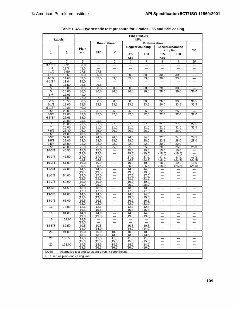
© American Petroleum Institute API Specification 5CT/ ISO 11960:2001
109
Table C.45—Hydrostatic test pressure for Grades J55 and K55 casing
Test pressureMPaLabels
Round thread Buttress threadRegular coupling Special-clearance
coupling1 2
Plainend STC LC J55
K55L80 J55
K55L80
XC
1 2 3 4 5 6 7 8 9 103-1/2 a 9.91 50,0 — — — — — — —
4 a 11.34 43,5 — — — — — — —4-1/2 9.50 27,5 27,5 — — — — — —4-1/2 10.50 30,0 30,0 — 30,0 30,0 30,0 30,0 —4-1/2 11.60 33,5 33,5 33,5 33,5 33,5 30,5 33,5 —
4-1/2 a 13.04 39,0 — — — — — — —5 11.50 26,5 26,5 — — — — — —5 13.00 30,5 30,5 30,5 30,5 30,5 28,5 30,5 —5 15.00 36,0 36,0 36,0 36,0 36,0 28,0 36,0 36,0
5 a 17.93 44,0 — — — — — — —5-1/2 14.00 27,0 27,0 — — — — — —5-1/2 15.50 30,5 30,5 30,5 30,5 30,5 26,0 30,5 30,55-1/2 17.00 33,5 33,5 33,5 33,5 33,5 26,0 33,5 33,5
5-1/2 a 19.81 40,0 — — — — — — —6-5/8 20.00 26,5 26,5 26,5 26,5 26,5 22,5 26,5 —6-5/8 24.00 32,0 32,0 32,0 32,0 32,0 22,5 32,0 32,0
6-5/8 a 27.65 38,0 — — — — — — —7 20.00 23,5 23,5 — — — — — —7 23.00 27,5 27,5 27,5 27,5 27,5 21,5 27,5 27,57 26.00 31,5 31,5 31,5 31,5 31,5 21,5 31,5 31,5
7-5/8 26.40 26,0 26,0 26,0 26,0 26,0 25,0 26,0 —8-5/8 24.00 18,5 18,5 — — — — — —8-5/8 32.00 24,5 24,5 24,5 24,5 24,5 22,5 24,5 24,58-5/8 36.00 28,0 28,0 28,0 28,0 28,0 22,5 28,0 28,09-5/8 36.00 22,0 22,0 22,0 22,0 22,0 20,0 22,0 —9-5/8 40.00 25,0 25,0 25,0 25,0 25,0 20,0 25,0 25,0
10-3/4 40.50 15,0(19,5)
15,0(19,5)
——
15,0(19,5)
15,0(19,5)
15,0(18,0)
15,0(19,5)
——
10-3/4 45.50 17,0(22,5)
17,0(22,5)
——
17,0(22,5)
17,0(22,5)
17,0(18,0)
17,0(22,5)
17,0(22,5)
10-3/4 51.00 19,0(25,5)
19,0(25,5)
——
19,0(25,5)
19,0(25,5)
18,0(18,0)
19,0(25,5)
19,0(25,5)
11-3/4 47.00 14,5(19,5)
14,5(19,5)
——
14,5(19,5)
14,5(19,5)
——
——
——
11-3/4 54.00 17,0(22,5)
17,0(22,5)
——
17,0(22,5)
17,0(22,5)
——
——
——
11-3/4 60.00 19,0(25,0)
19,0(25,0)
——
19,0(25,0)
19,0(25,0)
——
——
——
13-3/8 54.50 13,0(17,0)
13,0(17,0)
——
13,0(17,0)
13,0(17,0)
——
——
——
13-3/8 61.00 14,5(19,5)
14,5(19,5)
——
14,5(19,5)
14,5(19,5)
——
——
——
13-3/8 68.00 16,5(22,0)
16,5(22,0)
——
16,5(22,0)
16,5(22,0)
——
——
——
16 75.00 12,5(16,5)
12,5(16,5)
——
12,5(16,5)
12,5(16,5)
——
——
——
16 84.00 14,0(19,0)
14,0(19,0)
——
14,0(19,0)
14,0(19,0)
——
——
——
16 109.00 18,5(25,0)
——
——
——
——
——
——
——
18-5/8 87.50 10,5(14,0)
10,5(14,0)
——
10,5(14,0)
10,5(14,0)
——
——
——
20 94.00 10,0(13,5)
10,0(13,5)
10,0(13,5)
10,0(13,5)
10,0(13,5)
——
——
——
20 106.50 11,5(15,0)
11,5(15,0)
11,5(15,0)
11,5(15,0)
11,5(15,0)
——
——
——
20 133.00 14,5(19,5)
14,5(16,5)
14,5(16,5)
14,5(16,0)
14,5(16,0)
——
——
——
NOTE Alternative test pressures are given in parentheses.a Used as plain-end casing liner.

API Specification 5CT/ ISO 11960:2001 © American Petroleum Institute
110
Table C.46—Hydrostatic test pressure for Grade M65 casing
Test pressureMPaLabels
Round thread Buttress thread a
1 2
Plain end
STC LCRegularcoupling
Special-clearancecoupling
1 2 3 4 5 6 7
4-1/2 9.50 32,5 32,5 — — —4-1/2 10.50 35,5 35,5 — 35,5 35,54-1/2 11.60 40,0 — 40,0 40,0 40,04-1/2 13.50 46,0 — 46,0 46,0 44,0
5 11.50 31,5 31,5 — — —5 13.00 36,5 36,5 36,5 36,5 36,55 15.00 42,5 — 42,5 42,5 41,05 18.00 52,0 — 52,0 52,0 41,05 21.40 62,5 — 59,5 54,5 41,0
5-1/2 14.00 32,0 32,0 — — —5-1/2 15.50 36,0 36,0 36,0 36,0 36,05-1/2 17.00 39,5 — 39,5 39,5 38,05-1/2 20.00 47,0 — 47,0 47,0 38,05-1/2 23.00 54,0 — 54,0 49,5 38,06-5/8 20.00 31,0 31,0 31,0 31,0 31,06-5/8 24.00 36,0 — 36,0 36,0 32,56-5/8 28.00 45,0 — 45,0 45,0 32,5
7 20.00 28,0 28,0 — — —7 23.00 32,5 — 32,5 32,5 31,57 26.00 37,0 — 37,0 37,0 31,57 29.00 42,0 — 42,0 42,0 31,57 32.00 46,5 — 46,5 46,5 31,5
7-5/8 26.40 31,0 31,0 31,0 31,0 31,07-5/8 29.70 35,0 — 35,0 35,0 35,07-5/8 33.70 40,5 — 40,5 40,5 36,08-5/8 24.00 22,0 22,0 — — —8-5/8 28.00 25,5 25,5 — — —8-5/8 32.00 29,5 29,5 29,5 29,5 29,58-5/8 36.00 33,0 33,0 33,0 33,0 32,58-5/8 40.00 37,5 — 37,5 37,5 32,59-5/8 36.00 26,0 26,0 26,0 26,0 26,09-5/8 40.00 29,5 29,5 29,5 29,5 29,59-5/8 43.50 32,5 — 32,5 32,5 29,59-5/8 47.00 35,0 — 35,0 35,0 29,5
10-3/4 40.50 23,5 23,5 — 23,5 23,510-3/4 45.50 26,5 26,5 — 26,5 26,510-3/4 51.00 30,0 30,0 — 30,0 26,510-3/4 55.50 33,0 33,0 — 33,0 26,511-3/4 47.00 23,0 23,0 — 23,0 —11-3/4 54.00 26,5 26,5 — 26,5 —11-3/4 60.00 30,0 30,0 — 30,0 —13-3/8 54.50 20,5 20,5 — 20,5 —13-3/8 61.00 23,0 23,0 — 23,0 —13-3/8 68.00 25,5 25,5 — 25,5 —
16 75.00 19,5 19,5 — 19,5 —16 84.00 22,0 22,0 — 22,0 —
18-5/8 87.50 16,5 16,5 — 16,5 —20 94.00 15,5 14,5 15,5 15,5 —20 106.50 18,0 14,5 16,5 16,0 —
a Threaded and coupled grade M65 casing shall be furnished with grade L80 couplings.
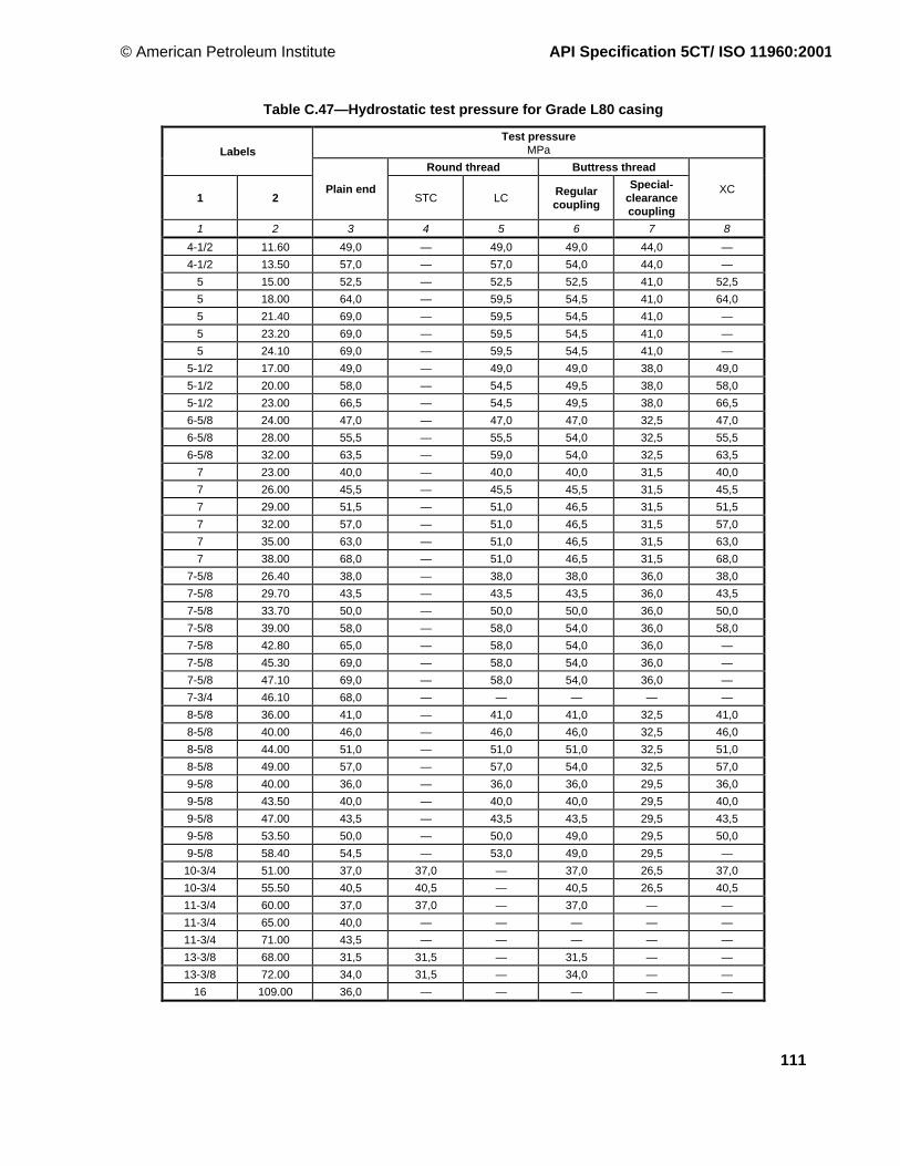
© American Petroleum Institute API Specification 5CT/ ISO 11960:2001
111
Table C.47—Hydrostatic test pressure for Grade L80 casing
Test pressureMPaLabels
Round thread Buttress thread
1 2Plain end
STC LCRegularcoupling
Special-clearancecoupling
XC
1 2 3 4 5 6 7 8
4-1/2 11.60 49,0 — 49,0 49,0 44,0 —
4-1/2 13.50 57,0 — 57,0 54,0 44,0 —
5 15.00 52,5 — 52,5 52,5 41,0 52,5
5 18.00 64,0 — 59,5 54,5 41,0 64,0
5 21.40 69,0 — 59,5 54,5 41,0 —
5 23.20 69,0 — 59,5 54,5 41,0 —
5 24.10 69,0 — 59,5 54,5 41,0 —
5-1/2 17.00 49,0 — 49,0 49,0 38,0 49,0
5-1/2 20.00 58,0 — 54,5 49,5 38,0 58,0
5-1/2 23.00 66,5 — 54,5 49,5 38,0 66,5
6-5/8 24.00 47,0 — 47,0 47,0 32,5 47,0
6-5/8 28.00 55,5 — 55,5 54,0 32,5 55,5
6-5/8 32.00 63,5 — 59,0 54,0 32,5 63,5
7 23.00 40,0 — 40,0 40,0 31,5 40,0
7 26.00 45,5 — 45,5 45,5 31,5 45,5
7 29.00 51,5 — 51,0 46,5 31,5 51,5
7 32.00 57,0 — 51,0 46,5 31,5 57,0
7 35.00 63,0 — 51,0 46,5 31,5 63,0
7 38.00 68,0 — 51,0 46,5 31,5 68,0
7-5/8 26.40 38,0 — 38,0 38,0 36,0 38,0
7-5/8 29.70 43,5 — 43,5 43,5 36,0 43,5
7-5/8 33.70 50,0 — 50,0 50,0 36,0 50,0
7-5/8 39.00 58,0 — 58,0 54,0 36,0 58,0
7-5/8 42.80 65,0 — 58,0 54,0 36,0 —
7-5/8 45.30 69,0 — 58,0 54,0 36,0 —
7-5/8 47.10 69,0 — 58,0 54,0 36,0 —
7-3/4 46.10 68,0 — — — — —
8-5/8 36.00 41,0 — 41,0 41,0 32,5 41,0
8-5/8 40.00 46,0 — 46,0 46,0 32,5 46,0
8-5/8 44.00 51,0 — 51,0 51,0 32,5 51,0
8-5/8 49.00 57,0 — 57,0 54,0 32,5 57,0
9-5/8 40.00 36,0 — 36,0 36,0 29,5 36,0
9-5/8 43.50 40,0 — 40,0 40,0 29,5 40,0
9-5/8 47.00 43,5 — 43,5 43,5 29,5 43,5
9-5/8 53.50 50,0 — 50,0 49,0 29,5 50,0
9-5/8 58.40 54,5 — 53,0 49,0 29,5 —
10-3/4 51.00 37,0 37,0 — 37,0 26,5 37,0
10-3/4 55.50 40,5 40,5 — 40,5 26,5 40,5
11-3/4 60.00 37,0 37,0 — 37,0 — —
11-3/4 65.00 40,0 — — — — —
11-3/4 71.00 43,5 — — — — —
13-3/8 68.00 31,5 31,5 — 31,5 — —
13-3/8 72.00 34,0 31,5 — 34,0 — —
16 109.00 36,0 — — — — —

API Specification 5CT/ ISO 11960:2001 © American Petroleum Institute
112
Table C.48—Hydrostatic test pressure for Grade N80 Type 1 and N80Q casing
Test pressureMPa
LabelsRound thread Buttress thread
Regular couplingSpecial-clearance
coupling1 2
Plainend
STC LCN80 P110 N80 P110
XC
1 2 3 4 5 6 7 8 9 10
4-1/2 11.60 49,0 — 49,0 49,0 49,0 44,0 49,0 —4-1/2 13.50 57,0 — 57,0 54,0 57,0 44,0 57,0 —
5 15.00 52,5 — 52,5 52,5 52,5 41,0 52,5 52,55 18.00 64,0 — 59,5 54,5 64,0 41,0 56,5 64,05 21.40 69,0 — 59,5 54,5 69,0 41,0 56,5 —5 23.20 69,0 — 59,5 54,5 69,0 41,0 56,5 —
5 24.10 69,0 — 59,5 54,5 69,0 41,0 56,5 —5-1/2 17.00 49,0 — 49,0 49,0 49,0 38,0 49,0 49,05-1/2 20.00 58,0 — 54,5 49,5 58,0 38,0 52,0 58,05-1/2 23.00 66,5 — 54,5 49,5 66,5 38,0 52,0 66,5
6-5/8 24.00 47,0 — 47,0 47,0 47,0 32,5 45,0 47,06-5/8 28.00 55,5 — 55,5 54,0 55,5 32,5 45,0 55,56-5/8 32.00 63,5 — 59,0 54,0 63,5 32,5 45,0 63,5
7 23.00 40,0 — 40,0 40,0 40,0 31,5 40,0 40,07 26.00 45,5 — 45,5 45,5 45,5 31,5 43,5 45,5
7 29.00 51,5 — 51,0 46,5 51,5 31,5 43,5 51,57 32.00 57,0 — 51,0 46,5 57,0 31,5 43,5 57,07 35.00 63,0 — 51,0 46,5 63,0 31,5 43,5 63,07 38.00 68,0 — 51,0 46,5 64,0 31,5 43,5 68,0
7-5/8 26.40 38,0 — 38,0 38,0 38,0 36,0 38,0 38,07-5/8 29.70 43,5 — 43,5 43,5 43,5 36,0 43,5 43,57-5/8 33.70 50,0 — 50,0 50,0 50,0 36,0 49,5 50,07-5/8 39.00 58,0 — 58,0 54,0 58,0 36,0 49,5 58,0
7-5/8 42.80 65,0 — 58,0 54,0 65,0 36,0 49,5 —7-5/8 45.30 69,0 — 58,0 54,0 69,0 36,0 49,5 —7-5/8 47.10 69,0 — 58,0 54,0 69,0 36,0 49,5 —7-3/4 46.10 68,0 — — — — — — —
8-5/8 36.00 41,0 — 41,0 41,0 41,0 32,5 41,0 41,08-5/8 40.00 46,0 — 46,0 46,0 46,0 32,5 44,0 46,08-5/8 44.00 51,0 — 51,0 51,0 51,0 32,5 44,0 51,08-5/8 49.00 57,0 — 57,0 54,0 57,0 32,5 44,0 57,0
9-5/8 40.00 36,0 — 36,0 36,0 36,0 29,5 35,5 36,09-5/8 43.50 40,0 — 40,0 40,0 40,0 29,5 35,5 40,09-5/8 47.00 43,5 — 43,5 43,5 43,5 29,5 35,5 43,59-5/8 53.50 50,0 — 50,0 49,0 50,0 29,5 35,5 50,0
9-5/8 58.40 54,5 — 53,0 49,0 54,5 29,5 35,5 —10-3/4 51.00 37,0 37,0 — 37,0 37,0 26,5 28,5 37,010-3/4 55.50 40,5 40,5 — 40,5 40,5 26,5 28,5 40,511-3/4 60.00 37,0 37,0 — 37,0 37,0 — — —
11-3/4 65.00 40,0 — — — — — — —11-3/4 71.00 43,5 — — — — — — —13-3/8 68.00 31,5 31,5 — 31,5 31,5 — — —13-3/8 72.00 34,0 31,5 — 34,0 34,0 — — —
16 109.00 36,0 — — — — — — —

© American Petroleum Institute API Specification 5CT/ ISO 11960:2001
113
Table C.49—Hydrostatic test pressure for Grade C90 casing
Test pressureMPaLabels
Round thread Buttress thread
1 2Plain end
STC LCRegularcoupling
Special-clearancecoupling
XC
1 2 3 4 5 6 7 8
4-1/2 11.60 55,0 — 55,0 55,0 49,5 —
4-1/2 13.50 64,0 — 64,0 61,0 49,5 —
5 15.00 59,0 — 59,0 59,0 46,5 59,0
5 18.00 69,0 — 67,0 61,5 46,5 69,0
5 21.40 69,0 — 67,0 61,5 46,5 —
5 23.20 69,0 — 67,0 61,5 46,5 —
5 24.10 69,0 — 67,0 61,5 46,5 —
5-1/2 17.00 55,0 — 55,0 55,0 42,5 55,0
5-1/2 20.00 65,0 — 61,5 56,0 42,5 65,0
5-1/2 23.00 69,0 — 61,5 56,0 42,5 69,0
5-1/2 26.80 69,0 — — — — —
5-1/2 29.70 69,0 — — — — —
5-1/2 32.60 69,0 — — — — —
5-1/2 35.30 69,0 — — — — —
5-1/2 38.00 69,0 — — — — —
5-1/2 40.50 69,0 — — — — —
5-1/2 43.10 69,0 — — — — —
6-5/8 24.00 53,0 — 53,0 53,0 36,5 53,0
6-5/8 28.00 62,5 — 62,5 61,0 36,5 62,5
6-5/8 32.00 69,0 — 66,5 61,0 36,5 69,0
7 23.00 45,0 — 45,0 45,0 35,5 45,0
7 26.00 51,5 — 51,5 51,5 35,5 51,5
7 29.00 58,0 — 57,5 52,5 35,5 58,0
7 32.00 64,5 — 57,5 52,5 35,5 64,5
7 35.00 69,0 — 57,5 52,5 35,5 69,0
7 38.00 69,0 — 57,5 52,5 35,5 69,0
7 42.70 69,0 — — — — —
7 46.40 69,0 — — — — —
7 50.10 69,0 — — — — —
7 53.60 69,0 — — — — —
7 57.10 69,0 — — — — —
7-5/8 26.40 42,5 — 42,5 42,5 40,5 42,5
7-5/8 29.70 49,0 — 49,0 49,0 40,5 49,0
7-5/8 33.70 56,0 — 56,0 56,0 40,5 56,0
7-5/8 39.00 65,0 — 65,0 61,0 40,5 65,0
7-5/8 42.80 69,0 — 65,0 61,0 40,5 —
7-5/8 45.30 69,0 — 65,0 61,0 40,5 —
7-5/8 47.10 69,0 — 65,0 61,0 40,5 —
7-5/8 51.20 69,0 — — — — —
7-5/8 55.30 69,0 — — — — —
7-3/4 46.10 69,0 — — — — —
8-5/8 36.00 46,0 — 46,0 46,0 36,5 46,0
8-5/8 40.00 52,0 — 52,0 52,0 36,5 52,0
8-5/8 44.00 57,5 — 57,5 57,5 36,5 57,5
8-5/8 49.00 64,0 — 64,0 60,5 36,5 64,0

API Specification 5CT/ ISO 11960:2001 © American Petroleum Institute
114
Table C.49 (continued )
Test pressureMPaLabels
Round thread Buttress thread
1 2Plain end
STC LCRegularcoupling
Special-clearancecoupling
XC
1 2 3 4 5 6 7 8
9-5/8 40.00 41,0 — 41,0 41,0 33,0 41,0
9-5/8 43.50 45,0 — 45,0 45,0 33,0 45,0
9-5/8 47.00 48,5 — 48,5 48,5 33,0 48,5
9-5/8 53.50 56,0 — 56,0 55,0 33,0 56,0
9-5/8 58.40 61,5 — 58,5 55,0 33,0 —
9-5/8 59.40 63,0 — — — — —
9-5/8 64.90 69,0 — — — — —
9-5/8 70.30 69,0 — — — — —
9-5/8 75.60 69,0 — — — — —
10-3/4 51.00 41,5 41,5 — 41,5 28,5 41,5
10-3/4 55.50 45,5 45,5 — 45,5 28,5 45,5
10-3/4 60.70 50,5 47,5 — 49,5 28,5 50,5
10-3/4 65.70 55,0 47,5 — 49,5 28,5 —
10-3/4 73.20 62,0 — — — — —
10-3/4 79.20 68,0 — — — — —
10-3/4 85.30 69,0 — — — — —
11-3/4 60.00 41,5 40,0 — 41,5 — —
11-3/4 65.00 45,0 — — — — —
11-3/4 71.00 49,0 — — — — —
13-3/8 68.00 35,5 31,5 — 34,0 — —
13-3/8 72.00 38,0 31,5 — 34,0 — —

© American Petroleum Institute API Specification 5CT/ ISO 11960:2001
115
Table C.50—Hydrostatic test pressure for Grade C95 casing
Test pressure, MPaLabels
Round thread Buttress thread
1 2Plain end
STC LCRegularcoupling
Special-clearancecoupling
XC
1 2 3 4 5 6 7 8
4-1/2 11.60 58,0 — 58,0 58,0 52,5 —
4-1/2 13.50 67,5 — 67,5 64,0 52,5 —
5 15.00 62,0 — 62,0 62,0 49,0 62,0
5 18.00 69,0 — 69,0 65,0 49,0 69,0
5 21.40 69,0 — 69,0 65,0 49,0 —
5 23.20 69,0 — 69,0 65,0 49,0 —
5 24.10 69,0 — 69,0 65,0 49,0 —
5-1/2 17.00 58,0 — 58,0 58,0 45,0 58,0
5-1/2 20.00 69,0 — 64,5 59,0 45,0 69,0
5-1/2 23.00 69,0 — 64,5 59,0 45,0 69,0
6-5/8 24.00 55,5 — 55,5 55,5 38,5 55,5
6-5/8 28.00 66,0 — 66,0 64,5 38,5 66,0
6-5/8 32.00 69,0 — 69,0 64,5 38,5 69,0
7 23.00 47,5 — 47,5 47,5 37,5 47,5
7 26.00 54,0 — 54,0 54,0 37,5 54,0
7 29.00 61,0 — 60,5 55,5 37,5 61,0
7 32.00 68,0 — 60,5 55,5 37,5 68,0
7 35.00 69,0 — 60,5 55,5 37,5 69,0
7 38.00 69,0 — 60,5 55,5 37,5 69,0
7-5/8 26.40 45,0 — 45,0 45,0 43,0 45,0
7-5/8 29.70 51,5 — 51,5 51,5 43,0 51,5
7-5/8 33.70 59,0 — 59,0 59,0 43,0 59,0
7-5/8 39.00 68,5 — 68,5 64,0 43,0 68,5
7-5/8 42.80 69,0 — 68,5 64,0 43,0 —
7-5/8 45.30 69,0 — 68,5 64,0 43,0 —
7-5/8 47.10 69,0 — 68,5 64,0 43,0 —
7-3/4 46.10 69,0 — — — — —
8-5/8 36.00 48,5 — 48,5 48,5 38,5 48,5
8-5/8 40.00 54,5 — 54,5 54,5 38,5 54,5
8-5/8 44.00 61,0 — 61,0 61,0 38,5 61,0
8-5/8 49.00 67,5 — 67,5 64,0 38,5 67,5
9-5/8 40.00 43,0 — 43,0 43,0 35,0 43,0
9-5/8 43.50 47,5 — 47,5 47,5 35,0 47,5
9-5/8 47.00 51,5 — 51,5 51,5 35,0 51,5
9-5/8 53.50 59,5 — 58,5 58,0 35,0 59,5
9-5/8 58.40 65,0 — 58,5 58,0 35,0 —
10-3/4 51.00 44,0 44,0 — 44,0 28,5 44,0
10-3/4 55.50 48,0 47,5 — 48,0 28,5 48,0
11-3/4 60.00 43,5 40,0 — 43,5 — —
11-3/4 65.00 47,5 — — — — —
11-3/4 71.00 52,0 — — — — —
13-3/8 68.00 37,5 31,5 — 34,0 — —
13-3/8 72.00 40,5 31,5 — 34,0 — —
16 109.00 43,0 — — — — —

API Specification 5CT/ ISO 11960:2001 © American Petroleum Institute
116
Table C.51—Hydrostatic test pressure for Grade T95 casingTest pressure
MPaLabelsRound thread Buttress thread
1 2
Plain end
STC LC Regularcoupling
Special-clearancecoupling
XC
1 2 3 4 5 6 7 84-1/2 11.60 58.0 — 58.0 58.0 52.5 —4-1/2 13.50 67,5 — 67,5 64,0 52,5 —
5 15.00 62,0 — 62,0 62,0 49,0 62,05 18.00 69,0 — 69,0 65,0 49,0 69,05 21.40 69,0 — 69,0 65,0 49,0 —5 23.20 69,0 — 69,0 65,0 49,0 —5 24.10 69,0 — 69,0 65,0 49,0 —
5-1/2 17.00 58,0 — 58,0 58,0 45,0 58,05-1/2 20.00 69,0 — 64,5 59,0 45,0 69,05-1/2 23.00 69,0 — 64,5 59,0 45,0 69,05-1/2 26.80 69,0 — — — — —5-1/2 29.70 69,0 — — — — —5-1/2 32.60 69,0 — — — — —5-1/2 35,30 69,0 — — — — —5-1/2 38.00 69,0 — — — — —5-1/2 40.50 69,0 — — — — —5-1/2 43.10 69,0 — — — — —6-5/8 24.00 55,5 — 55,5 55,5 38,5 55,56-5/8 28.00 66,0 — 66,0 64,5 38,5 66,06-5/8 32.00 69,0 — 69,0 64,5 38,5 69,0
7 23.00 47,5 — 47,5 47,5 37,5 47,57 26.00 54,0 — 54,0 54,0 37,5 54,07 29.00 61,0 — 60,5 55,5 37,5 61,07 32.00 68,0 — 60,5 55,5 37,5 68,07 35.00 69,0 — 60,5 55,5 37,5 69,07 38.00 69,0 — 60,5 55,5 37,5 69,07 42.70 69,0 — — — — —7 46.40 69,0 — — — — —7 50.10 69,0 — — — — —7 53.60 69,0 — — — — —7 57.10 69,0 — — — — —
7-5/8 26.40 45,0 — 45,0 45,0 43,0 45,07-5/8 29.70 51,5 — 51,5 51,5 43,0 51,57-5/8 33.70 59,0 — 59,0 59,0 43,0 59,07-5/8 39.00 68,5 — 68,5 64,0 43,0 68,57-5/8 42.80 69,0 — 68,5 64,0 43,0 —7-5/8 45.30 69,0 — 68,5 64,0 43,0 —7-5/8 47.10 69,0 — 68,5 64,0 43,0 —7-5/8 51.20 69,0 — — — — —7-5/8 55.30 69,0 — — — — —7-3/4 46.10 69,0 — — — — —8-5/8 36.00 48,5 — 48,5 48,5 38,5 48,58-5/8 40.00 54,5 — 54,5 54,5 38,5 54,58-5/8 44.00 61,0 — 61,0 61,0 38,5 61,08-5/8 49.00 67,5 — 67,5 64,0 38,5 67,59-5/8 40.00 43,0 — 43,0 43,0 35,0 43,09-5/8 43.50 47,5 — 47,5 47,5 35,0 47,59-5/8 47.00 51,5 — 51,5 51,5 35,0 51,59-5/8 53.50 59,5 — 58,5 58,0 35,0 59,59-5/8 58.40 65,0 — 58,5 58,0 35,0 —9-5/8 59.40 66,5 — — — — —9-5/8 64.90 69,0 — — — — —9-5/8 70.30 69,0 — — — — —9-5/8 75.60 69,0 — — — — —
10-3/4 51.00 44,0 44,0 — 44,0 28,5 44,010-3/4 55.50 48,0 47,5 — 48,0 28,5 48,010-3/4 60.70 53,0 47,5 — 51,5 28,5 53,010-3/4 65.70 58,0 47,5 — 51,5 28,5 —10-3/4 73.20 65,5 — — — — —10-3/4 79.20 69,0 — — — — —10-3/4 85.30 69,0 — — — — —11-3/4 60.00 43,5 40,0 — 43,5 — —11-3/4 65.00 47,5 — — — — —11-3/4 71.00 52,0 — — — — —13-3/8 68.00 37,5 31,5 — 34,0 — —13-3/8 72.00 40,5 31,5 — 34,0 — —

© American Petroleum Institute API Specification 5CT/ ISO 11960:2001
117
Table C.52—Hydrostatic test pressure for Grade P110 casing
Test pressureMPa
Round thread Buttress threadLabels
Regular coupling Special-clearancecoupling
1 2
Plainend STC LC
P110 Q125 P110 Q125
XC
1 2 3 4 5 6 7 8 9 10
4-1/2 11.60 67,5 — 67,5 67,5 67,5 60,5 67,5 —4-1/2 13.50 69,0
(78,0)——
69,0(78,0)
69,0(74,0)
69,0(78,0)
60,5(60,5)
69,0(69,0)
——
4-1/2 15.10 69,0(91,0)
——
69,0(80,5)
69,0(74,0)
69,0(84,5)
60,5(60,5)
69,0(69,0)
——
5 15.00 69,0(72,0)
——
69,0(72,0)
69,0(72,0)
69,0(72,0)
56,5(56,5)
64,5(64,5)
69,0(72,0)
5 18.00 69,0(88,0)
——
69,0(82,0)
69,0(75,0)
69,0(85,5)
56,5(56,5)
64,5(64,5)
69,0(88,0)
5 21.40 69,0(106,0)
——
69,0(82,0)
69,0(75,0)
69,0(85,5)
56,5(56,5)
64,5(64,5)
——
5 23.20 69,0(116,0)
——
69,0(82,0)
69,0(75,0)
69,0(85,5)
56,5(56,5)
64,5(64,5)
——
5 24.10 69,0(121,5)
——
69,0(82,0)
69,0(75,0)
69,0(85,5)
56,5(56,5)
64,5(64,5)
——
5-1/2 17.00 67,0 — 67,0 67,0 67,0 52,0 59,5 67,05-1/2 20.00 69,0
(79,5)——
69,0(75,0)
68,0(68,0)
69,0(77,5)
52,0(52,0)
59,5(59,5)
69,0(79,5)
5-1/2 23.00 69,0(91,5)
——
69,0(75,0)
68,0(68,0)
69,0(77,5)
52,0(52,0)
59,5(59,5)
69,0(91,5)
6-5/8 24.00 64,5 — 64,5 64,5 64,5 45,0 51,0 64,56-5/8 28.00 69,0
(76,5)——
69,0(76,5)
69,0(74,5)
69,0(76,5)
45,0(45,0)
51,0(51,0)
69,0(76,5)
6-5/8 32.00 69,0(87,0)
——
69,0(81,0)
69,0(74,5)
69,0(84,5)
45,0(45,0)
51,0(51,0)
69,0(87,0)
7 26.00 62,5 — 62,5 62,5 62,5 43,5 49,5 62,57 29.00 69,0
(70,5)——
65,5(65,5)
64,0(64,0)
69,0(70,5)
43,5(43,5)
49,5(49,5)
69,0(70,5)
7 32.00 69,0(78,5)
——
65,5(65,5)
64,0(64,0)
69,0(73,0)
43,5(43,5)
49,5(49,5)
69,0(78,5)
7 35.00 69,0(86,5)
——
65,5(65,5)
64,0(64,0)
69,0(73,0)
43,5(43,5)
49,5(49,5)
69,0(86,5)
7 38.00 69,0(93,5)
——
65,5(65,5)
64,0(64,0)
69,0(73,0)
43,5(43,5)
49,5(49,5)
69,0(93,5)
7-5/8 29.70 59,5 — 59,5 59,5 59,5 49,5 55,5 59,57-5/8 33.70 68,5 — 68,5 68,5 68,5 49,5 55,5 68,57-5/8 39.00 69,0
(79,5)——
69,0(79,5)
69,0(74,0)
69,0(79,5)
49,5(49,5)
55,5(55,5)
69,0(79,5)
7-5/8 42.80 69,0(89,5)
——
69,0(79,5)
69,0(74,0)
69,0(84,5)
49,5(49,5)
55,5(55,5)
——
7-5/8 45.30 69,0(94,5)
——
69,0(79,5)
69,0(74,0)
69,0(84,5)
49,5(49,5)
55,5(55,5)
——
7-5/8 47.10 69,0(99,5)
——
69,0(79,5)
69,0(74,0)
69,0(84,5)
49,5(49,5)
55,5(55,5)
——
7-3/4 46.10 69,0(93,0)
——
——
——
——
——
——
——
8-5/8 40.00 63,5 63,5 — 63,5 63,5 44,0 44,0 —8-5/8 44.00 69,0
(70,5)——
69,0(70,5)
69,0(70,5)
69,0(70,5)
44,0(44,0)
44,0(44,0)
69,0(70,5)

API Specification 5CT/ ISO 11960:2001 © American Petroleum Institute
118
Table C.52 (continued )
Test pressureMPa
Round thread Buttress threadLabels
Regular coupling Special-clearancecoupling
1 2
Plainend STC LC
P110 Q125 P110 Q125
XC
1 2 3 4 5 6 7 8 9 10
8-5/8 49.00 69,0
(78,5)
—
—
69,0
(71,5)
69,0
(74,0)
69,0
(77,5)
44,0
(44,0)
44,0
(44,0)
69,0
(78,5)
9-5/8 43.50 55,0 — 55,0 55,0 55,0 35,5 35,5 55,0
9-5/8 47.00 59,5 — 59,5 59,5 59,5 35,5 35,5 59,5
9-5/8 53.50 68,5 — 67,0 63,0 63,0 35,5 35,5 68,5
9-5/8 58.40 69,0
(75,0)
—
—
67,0
(67,0)
63,0
(63,0)
63,0
(63,0)
35,5
(35,5)
35,5
(35,5)
—
—
10-3/4 51.00 51,0 51,0 — 51,0 51,0 28,5 28,5 51,0
10-3/4 55.50 56,0 54,5 — 51,5 51,5 28,5 28,5 56,0
10-3/4 60.70 61,5 54,5 — 51,5 51,5 28,5 28,5 61,5
10-3/4 65.70 67,0 54,5 — 51,5 51,5 28,5 28,5 —
11-3/4 60.00 50,5 46,0 — 43,5 43,5 — — —
11-3/4 65.00 55,0 — — — — — — —
11-3/4 71.00 60,0 — — — — — — —
13-3/8 68.00 43,5 36,0 — 34,0 34,0 — — —
13-3/8 72.00 46,5 36,0 — 34,0 34,0 — — —
16 109.00 49,5 — — — — — — —
NOTE Alternative test pressures are given in parentheses.

© American Petroleum Institute API Specification 5CT/ ISO 11960:2001
119
Table C.53—Hydrostatic test pressure for Grade Q125 casing
Test pressureMPaLabels
Round thread
1 2Plain end
STC LC
Buttressthread,regular
coupling
XC
1 2 3 4 5 6 7
4-1/2 15.10 69,0
(103,5)
—
—
69,0
(92,0)
69,0
(84,5)
—
—
5 18.00 69,0
(100,0)
—
—
69,0
(93,5)
69,0
(85,5)
69,0
(100,0)
5 21.40 69,0
(120,5)
—
—
69,0
(93,5)
69,0
(85,5)
—
—
5 23.20 69,0
(132,0)
—
—
69,0
(93,5)
69,0
(85,5)
—
—
5 24.10 69,0
(138,0)
—
—
69,0
(93,5)
69,0
(85,5)
—
—
5-1/2 23.00 69,0
(104,0)
—
—
69,0
(85,0)
69,0
(77,5)
69,0
(104,0)
6-5/8 32.00 69,0
(99,0)
—
—
69,0
(81,5)
69,0
(84,5)
69,0
(99,0)
7 35.00 69,0
(98,0)
—
—
65,5
(65,5)
69,0
(73,0)
69,0
(98,0)
7 38.00 69,0
(106,5)
—
—
65,5
(65,5)
69,0
(73,0)
69,0
(106,5)
7-5/8 39.00 69,0
(90,5)
—
—
69,0
(81,5)
69,0
(84,5)
69,0
(90,5)
7-5/8 42.80 69,0
(101,5)
—
—
69,0
(81,5)
69,0
(84,5)
—
—
7-5/8 45.30 69,0
(107,5)
—
—
69,0
(81,5)
69,0
(84,5)
—
—
7-5/8 47.10 69,0
(113,0)
—
—
69,0
(81,5)
69,0
(84,5)
—
—
7-3/4 46.10 69,0
(106,0)
—
—
—
—
—
—
—
—
8-5/8 49.00 69,0
(89,0)
—
—
69,0
(71,5)
69,0
(77,5)
69,0
(89,0)
9-5/8 47.00 67,5 — 67,0 63,0 67,5
9-5/8 53.50 69,0
(78,0)
—
—
67,0
(67,0)
63,0
(63,0)
69,0
(78,0)
9-5/8 58.40 69,0
(85,0)
—
—
67,0
(67,0)
63,0
(63,0)
—
—
10-3/4 60.70 69,0
(70,0)
54,5
(54,5)
—
—
51,5
(51,5)
69,0
(70,0)
10-3/4 65.70 69,0
(76,5)
54,5
(54,5)
—
—
51,5
(51,5)
—
—
11-3/4 60.00 57,5 46,0 — 43,5 —
11-3/4 65.00 62,5 — — — —
11-3/4 71.00 68,5 — — — —
13-3/8 72.00 53,0 36,0 — 34,0 —
16 109.00 56,5 — — — —
NOTE Alternative test pressures are given in parentheses.

API Specification 5CT/ ISO 11960:2001 © American Petroleum Institute
120
Table C.54—Hydrostatic test pressure for Grade H40 tubing
Labels Test pressureMPa
2 External upset
Special-clearancecoupling
1
NUT&C
EUT&C
IJPlainend
Non-upsetT&C
Regularcoupling
H40 J55
Integraljoint
1 2 3 4 5 6 7 8 9 10
1.050 1.14 1.20 — 47,5 47,5 47,5 — — —
1.050 1.48 1.54 — 64,5 — 52,0 — — —
1.315 1.70 1.80 1.72 44,5 44,5 44,5 — 40,0
1.315 2.19 2.24 — 60,0 — 56,5 — — —
1.660 2.09 — 2.10 33,5 — — — — 32,0
1.660 2.30 2.40 2.33 37,5 37,5 37,5 — — 32,0
1.660 3.03 3.07 — 51,0 — 45,0 — — —
1.900 2.40 — 2.40 29,0 — — — — 28,5
1.900 2.75 2.90 2.76 33,5 33,5 33,5 — — 28,5
1.900 3.65 3.73 — 46,5 — 41,5 — — —
2.063 3.24 — 3.25 33,5 — — — — 28,0
2.063 4.50 — — 48,0 — — — — —
2-3/8 4.00 — — 31,0 31,0 — — — —
2-3/8 4.60 4.70 — 35,5 35,5 35,5 31,5 35,5 —
2-7/8 6.40 6.50 — 33,5 33,5 33,5 30,5 33,5 —
3-1/2 7.70 — — 37,5 37,5 — — — —
3-1/2 9.20 9.30 — 32,0 32,0 32,0 29,5 32,0 —
3-1/2 10.20 — — 36,5 36,5 — — — —
4 9.50 — — 25,0 25,0 — — — —
4 10.70 11.00 — 29,0 — 29,0 — — —
4-1/2 12.60 12.75 — 26,5 26,5 26,5 — — —

© American Petroleum Institute API Specification 5CT/ ISO 11960:2001
121
Table C.55—Hydrostatic test pressure for Grade J55 tubing
Labels Test pressureMPa
2 External upset
Special-clearancecoupling
1
NUT&C
EUT&C
IJPlainend
Non-upsetT&C
Regularcoupling
J55 L80
Integraljoint
1 2 3 4 5 6 7 8 9 10
1.050 1.14 1.20 — 65,5 65,5 65,5 — — —
1.050 1.48 1.54 — 69,0 — 69,0 — — —
1.315 1.70 1.80 1.72 61,5 61,5 61,5 — 55,0
1.315 2.19 2.24 — 69,0 — 69,0 — — —
1.660 2.09 — 2.10 45,5 — — — — 44,0
1.660 2.30 2.40 2.33 51,0 51,0 51,0 — — 44,0
1.660 3.03 3.07 — 69,0 — 62,0 — — —
1.900 2.40 — 2.40 40,0 — — — — 39,0
1.900 2.75 2.90 2.76 46,0 46,0 46,0 — — 39,0
1.900 3.65 3.73 — 64,0 — 57,0 — — —
2.063 3.24 — 3.25 46,0 — — — — 38,5
2.063 4.50 — — 66,0 — — — — —
2-3/8 4.00 — — 42,5 42,5 — — — —
2-3/8 4.60 4.70 — 48,5 48,5 48,5 43,5 48,5 —
2-7/8 6.40 6.50 — 46,0 46,0 46,0 42,0 46,0 —
3-1/2 7.70 — — 37,5 37,5 — — — —
3-1/2 9.20 9.30 — 44,0 44,0 44,0 40,5 44,0 —
3-1/2 10.20 — — 50,0 50,0 — — — —
4 9.50 — — 34,5 34,5 — — — —
4 10.70 11.00 — 39,5 — 39,5 — — —
4-1/2 12.60 12.75 — 36,5 36,5 36,5 — — —

API Specification 5CT/ ISO 11960:2001 © American Petroleum Institute
122
Table C.56—Hydrostatic test pressure for Grades N80 Type 1 and N80Q tubing
Labels Test pressureMPa
2 External upset
Special-clearancecoupling
1
NUT&C
EUT&C
IJPlainend
Non-upsetT&C
Regularcoupling
N80 P110
Integraljoint
1 2 3 4 5 6 7 8 9 10
1.050 1.14 1.20 — 69,0 69,0 69,0 — — —
1.050 1.48 1.54 — 69,0 — 69,0 — — —
1.315 1.70 1.80 1.72 69,0 69,0 69,0 — — 69,0
1.315 2.19 2.24 — 69,0 — 69,0 — — —
1.660 2.30 2.40 2.33 69,0 69,0 69,0 — — 64,0
1.660 3.03 3.07 — 69,0 69,0 69,0 — — —
1.900 2.75 2.90 2.76 67,5 67,5 67,5 — — 56,5
1.900 3.65 3.73 — 69,0 — 69,0 — — —
2.063 3.24 — 3.25 66,5 — — — — 56,5
2.063 4.50 — — 69,0 — — — — —
2-3/8 4.00 — — 62,0 62,0 — — — —
2-3/8 4.60 4.70 — 69,0 69,0 69,0 63,0 69,0 —
2-3/8 5.80 5.95 — 69,0 69,0 69,0 63,0 69,0 —
2-7/8 6.40 6.50 — 66,5 66,5 66,5 61,0 66,5 —
2-7/8 7.80 7.90 — 69,0 69,0 69,0 61,0 69,0 —
2-7/8 8.60 8.70 — 69,0 69,0 69,0 61,0 69,0 —
3-1/2 7.70 — — 54,5 54,5 — — — —
3-1/2 9.20 9.30 — 64,0 64,0 64,0 59,0 64,0 —
3-1/2 10.20 — — 69,0 69,0 — — — —
3-1/2 12.70 12.95 — 69,0 69,0 69,0 59,0 69,0 —
4 9.50 — — 50,0 50,0 — — — —
4 10.70 11.00 — 58,0 — 58,0 — — —
4-1/2 12.60 12.75 — 53,0 53,0 53,0 — — —

© American Petroleum Institute API Specification 5CT/ ISO 11960:2001
123
Table C.57—Hydrostatic test pressure for Grade L80 tubing
Labels Test pressureMPa
2 External upset1
NUT&C
EUT&C
IJPlainend
Non-upsetT&C
Regularcoupling
Special-clearancecoupling
Integraljoint
1 2 3 4 5 6 7 8 9
1.050 1.14 1.20 — 69,0 69,0 69,0 — —
1.050 1.48 1.54 — 69,0 — 69,0 — —
1.315 1.70 1.80 1.72 69,0 69,0 69,0 — 69,0
1.315 2.19 2.24 — 69,0 — 69,0 — —
1.660 2.30 2.40 2.33 69,0 69,0 69,0 — 64,0
1.660 3.03 3.07 — 69,0 — 69,0 — —
1.900 2.75 2.90 2.76 67,5 67,5 67,5 — 56,5
1.900 3.65 3.73 — 69,0 — 69,0 — —
1.900 4.42 — — 69,0 — — — —
1.900 5.15 — — 69,0 — — — —
2.063 3.24 — 3.25 66,5 — — — 56,5
2.063 4.50 — — 69,0 — — — —
2-3/8 4.00 — — 62,0 62,0 — — —
2-3/8 4.60 4.70 — 69,0 69,0 69,0 63,0 —
2-3/8 5.80 5.95 — 69,0 69,0 69,0 63,0 —
2-3/8 6.60 — — 69,0 — — — —
2-3/8 7.35 7.45 — 69,0 — 69,0 63,0 —
2-7/8 6.40 6.50 — 66,5 66,5 66,5 61,0 —
2-7/8 7.80 7.90 — 69,0 69,0 69,0 61,0 —
2-7/8 8.60 8.70 — 69,0 69,0 69,0 61,0 —
2-7/8 9.35 9.45 — 69,0 — 69,0 61,0 —
2-7/8 10.50 — — 69,0 — — — —
2-7/8 11.50 — — 69,0 — — — —
3-1/2 7.70 — — 54,5 54,5 — — —
3-1/2 9.20 9.30 — 64,0 64,0 64,0 59,0 —
3-1/2 10.20 — — 69,0 69,0 — — —
3-1/2 12.70 12.95 — 69,0 69,0 69,0 59,0 —
3-1/2 14.30 — — 69,0 — — — —
3-1/2 15.50 — — 69,0 — 69,0 — —
3-1/2 17.00 — — 69,0 — — — —
4 9.50 — — 50,0 50,0 — — —
4 10.70 11.00 — 58,0 — 58,0 — —
4 13.20 — — 69,0 — — — —
4 16.10 — — 69,0 — — — —
4 18.90 — — 69,0 — — — —
4 22.20 — — 69,0 — — — —
4-1/2 12.60 12.75 — 53,0 53,0 53,0 — —
4-1/2 15.20 — — 66,0 — — — —
4-1/2 17.00 — — 69,0 — — — —
4-1/2 18.90 — — 69,0 — — — —
4-1/2 21.50 — — 69,0 — — — —
4-1/2 23.70 — — 69,0 — — — —
4-1/2 26.10 — — 69,0 — — — —

API Specification 5CT/ ISO 11960:2001 © American Petroleum Institute
124
Table C.58—Hydrostatic test pressure for Grade C90 tubing
Labels Test pressureMPa
21
NUT&C
EUT&C
IJPlainend
Non-upsetT&C
External upsetregular coupling
Integraljoint
1 2 3 4 5 6 7 8
1.050 1.14 1.20 — 69,0 69,0 69,0 —
1.050 1.48 1.54 — 69,0 — 69,0 —
1.315 1.70 1.80 1.72 69,0 69,0 69,0 69,0
1.315 2.19 2.24 — 69,0 — 69,0 —
1.660 2.30 2.40 2.33 69,0 69,0 69,0 69,0
1.660 3.03 3.07 — 69,0 — 69,0 —
1.900 2.75 2.90 2.76 69,0 69,0 69,0 64,0
1.900 3.65 3.73 — 69,0 — 69,0 —
1.900 4.42 — — 69,0 — — —
1.900 5.15 — — 69,0 — — —
2.063 3.24 — 3.25 69,0 — — 63,5
2.063 4.50 — — 69,0 — — —
2-3/8 4.00 — — 69,0 69,0 — —
2-3/8 4.60 4.70 — 69,0 69,0 69,0 —
2-3/8 5.80 5.95 — 69,0 69,0 69,0 —
2-3/8 6,60 — — 69,0 — — —
2-3/8 7.35 7.45 — 69,0 — 69,0 —
2-7/8 6.40 6.50 — 69,0 69,0 69,0 —
2-7/8 7.80 7.90 — 69,0 69,0 69,0 —
2-7/8 8.60 8.70 — 69,0 69,0 69,0 —
2-7/8 9.35 9.45 — 69,0 — 69,0 —
2-7/8 10.50 — — 69,0 — — —
2-7/8 11.50 — — 69,0 — — —
3-1/2 7.70 — — 61,5 61,5 — —
3-1/2 9.20 9.30 — 69,0 69,0 69,0 —
3-1/2 10.20 — — 69,0 69,0 — —
3-1/2 12.70 12.95 — 69,0 69,0 69,0 —
3-1/2 14.30 — — 69,0 — — —
3-1/2 15.50 — — 69,0 — — —
3-1/2 17.00 — — 69,0 — — —
4 9.50 — — 56,0 56,0 — —
4 10.70 11.00 — 65,0 — 65,0 —
4 13.20 — — 69,0 — — —
4 16.10 — — 69,0 — — —
4 18.90 — — 69,0 — — —
4 22.20 — — 69,0 — — —
4-1/2 12.60 12.75 — 60,0 60,0 60,0 —
4-1/2 15.20 — — 69,0 — — —
4-1/2 17.00 — — 69,0 — — —
4-1/2 18.90 — — 69,0 — — —
4-1/2 21.50 — — 69,0 — — —
4-1/2 23.70 — — 69,0 — — —
4-1/2 26.10 — — 69,0 — — —

© American Petroleum Institute API Specification 5CT/ ISO 11960:2001
125
Table C.59—Hydrostatic test pressure for Grade T95 tubing
Labels Test pressureMPa
21NU
T&CEU
T&C IJPlainend
Non-upsetT&C
External upsetregular coupling
Integraljoint
1 2 3 4 5 6 7 8
1.050 1.14 1.20 — 69,0 69,0 69,0 —
1.050 1.48 1.54 — 69,0 — 69,0 —
1.315 1.70 1.80 1.72 69,0 69,0 69,0 69,0
1.315 2.19 2.24 — 69,0 — 69,0 —
1.660 2.30 2.40 2.33 69,0 69,0 69,0 69,0
1.660 3.03 3.07 — 69,0 — 69,0 —
1.900 2.75 2.90 2.76 69,0 69,0 69,0 67,5
1.900 3.65 3.73 — 69,0 — 69,0 —
1.900 4.42 — — 69,0 — — —
1.900 5.15 — — 69,0 — — —
2.063 3.24 — 3.25 69,0 — — 67,0
2.063 4.50 — — 69,0 — — —
2-3/8 4.00 — — 69,0 69,0 — —
2-3/8 4.60 4.70 — 69,0 69,0 69,0 —
2-3/8 5.80 5.95 — 69,0 69,0 69,0 —
2-3/8 6.60 — — 69,0 — — —
2-3/8 7.35 7.45 — 69,0 — 69,0 —
2-7/8 6.40 6.50 — 69,0 69,0 69,0 —
2-7/8 7.80 7.90 — 69,0 69,0 69,0 —
2-7/8 8.60 8.70 — 69,0 69,0 69,0 —
2-7/8 9.35 9.45 — 69,0 — 69,0 —
2-7/8 10.50 — — 69,0 — — —
2-7/8 11.50 — — 69,0 — — —
3-1/2 7.70 — — 64,5 64,5 — —
3-1/2 9.20 9.30 — 69,0 69,0 69,0 —
3-1/2 10.20 — — 69,0 69,0 — —
3-1/2 12.70 12.95 — 69,0 69,0 69,0 —
3-1/2 14.30 — — 69,0 — — —
3-1/2 15.50 — — 69,0 — — —
3-1/2 17.00 — — 69,0 — — —
4 9.50 — — 59,0 59,0 — —
4 10.70 11.00 — 68,5 — 68,5 —
4 13.20 — — 69,0 — — —
4 16.10 — — 69,0 — — —
4 18.90 — — 69,0 — — —
4 22.20 — — 69,0 — — —
4-1/2 12.60 12.75 — 63,0 63,0 63,0 —
4-1/2 15.20 — — 69,0 — — —
4-1/2 17.00 — — 69,0 — — —
4-1/2 18.90 — — 69,0 — — —
4-1/2 21.50 — — 69,0 — — —
4-1/2 23.70 — — 69,0 — — —
4-1/2 26.10 — — 69,0 — — —

API Specification 5CT/ ISO 11960:2001 © American Petroleum Institute
126
Table C.60—Hydrostatic test pressure for Grade P110 tubing
Test pressureMPaLabels
External upset
21
NUT&C
EUT&C
Plainend
Non-upsetT&C Regular
coupling
Special-clearancecoupling
1 2 3 4 5 6 7
1.050 1.48 1.54 69,0
(178,0)
—
—
69,0
(142,5)
—
—
1.315 2.19 2.24 69,0
(165,0)
—
—
69,0
(154,5)
—
—
1.660 3.03 3.07 69,0
(139,5)
—
—
69,0
(123,5)
—
—
1.900 2.75 2.90 69,0
(92,5)
—
—
69,0
(92,5)
—
—
2.063 4.50 — 69,0
(132,5)
—
—
—
—
—
—
2-3/8 4.60 4.70 69,0
(97,0)
69,0
(97,0)
69,0
(97,0)
69,0
(86,5)
2-3/8 5.80 5.95 69,0
(129,5)
69,0
(121,5)
69,0
(112,5)
69,0
(86,5)
2-7/8 6.40 6.50 69,0
(91,5)
69,0
(91,5)
69,0
(91,5)
69,0
(83,5)
2-7/8 7.80 7.90 69,0
(116,5)
69,0
(116,5)
69,0
(113,5)
69,0
(83,5)
2-7/8 8.60 8.70 69,0
(130,0)
69,0
(126,5)
69,0
(113,5)
69,0
(83,5)
3-1/2 9.20 9.30 69,0
(88,0)
69,0
(88,0)
69,0
(88,0)
69,0
(81,0)
3-1/2 12.70 12.95 69,0
(130,0)
69,0
(124,0)
69,0
(118,0)
69,0
(81,0)
NOTE Alternative test pressures are given in parentheses.

© American Petroleum Institute API Specification 5CT/ ISO 11960:2001
127
Table C.61—Summary of NDE methods for seamless and the body of welded pipe
GradeVisual
inspection(see 10.14)
Wallthickness
determination
Ultrasonicinspection
Flux leakageinspection
Eddy currentinspection
Magnetic particleinspection a
1 2 3 4 5 6 7
H40, J55
K55, N80 Type 1
R N N N N N
N80Q, L80
C95, M65
R R A A A A
P110 R R A A A NAC90, T95, Q125 R R C B B B
N = not required
R = required
A = one method or any combination of methods shall be used
B = at least one method shall be used in addition to ultrasonic inspection to inspect the outside surface
C = ultrasonic inspection shall be used to inspect the outside and inside surfaces
NA = not applicablea MPI is permitted for end-area inspection. MPI is permitted for pipe body outside-surface inspection in combination with othermethods of pipe body inspection.
Table C.62—Acceptance (inspection) levels
External imperfection Internal imperfectionGrade
Longitudinal Transverse Longitudinal Transverse
1 2 3 4 5
N80Q, M65, L80, C95 L4 — L4 —
P110 to A.9 (SR16) L4 L4 L4 L4
P110 L2 L2 L2 L2
P110 to A.9 (SR16) and A.2 (SR2) L2 L2 L2 L2
C90 UT L2 L2 L2 L2
T95-Q125 2nd method L2 L2 — —
Weld seam
P110, Q125 L2 N L2 N
All other grades L3 N L3 N
N = not required; L x = acceptance (inspection) level.
Table C.63—Artificial reference indicators
Acceptance(inspection) level
Notch depth a
max.%
Notch length
max. at full depthmm
Width
max.mm
Radially drilled holediameter b
mm
1 2 3 4 5
L2 5 50 1 1,6
L3 10 50 1 3,2
L4 12,5 50 1 3,2
a Depth as a percent of specified wall thickness. The depth tolerance shall be ± 15 % of the calculated notch depth with a minimumnotch depth of 0,3 mm ± 0,05 mm.b Drilled hole diameter (through the pipe wall) shall be based on the drill bit size.

API Specification 5CT/ ISO 11960:2001 © American Petroleum Institute
128
Table C.64—Size of stamp markings
Product Label 1 Marking heightmm
Pipe < 4-1/2
≥ 4-1/2
4,8
6,4
Coupling Pipe sizes < 4-1/2
Pipe sizes ≥ 4-1/2 to < 7-5/8
Pipe sizes ≥ 7-5/8
6,4
9,5
12,7
Table C.65—Grade colour codes
Grade Number and colour of bandsfor pipe and pup-joints 1,8 m Colour(s) for coupling
Type Entire coupling Band(s)
1 2 3 4 5
H40 None or black band at the manufacturer’s option None Same as for pipe
J55tubing
One bright green Bright green None
J55casing
One bright green Bright green One white
K55 Two bright green Bright green None
M65 One bright green, one blue M65 pipe uses L80 Type 1 couplings
N80 1 One red Red None
N80 Q One red, one bright green Red Green
L80 1 One red, one brown Red One brown
L80 9Cr One red, one brown, two yellow Red Two yellow
L80 13Cr One red, one brown, one yellow Red One yellow
C90 1 One purple Purple None
C90 2 One purple, one yellow Purple One yellow
T95 1 One silver Silver None
T95 2 One silver, one yellow Silver One yellow
C95 One brown Brown None
P110 One white White None
Q125 1 One orange Orange None
Q125 2 One orange, one yellow Orange One yellow
Q125 3 One orange, one green Orange One green
Q125 4 One orange, one brown Orange One brown
Table C.66—Thread type markings
Product Thread type Marked symbol
Casing Short round
Long round
Buttress
Extreme-line
STC
LC
BC
XC
Tubing Non-upset
External upset
Integral joint
NU
EU
IJ

© American Petroleum Institute API Specification 5CT/ ISO 11960:2001
129
Table C.67 Marking requirements and sequence
Stencil and/or stamp marking requirements a
Groups 1 and 3 Groups 2 and 4Marking sequence Mark or
symbolbPipe and
pup-jointsCouplings
andaccessories
Pipe andpup-joints
Couplingsand
accessories1 2 3 4 5 6 71 Manufacturer’s name or mark ..... D or P D or P P P2 ISO specification marking plus compatible standard at
manufacturer's option or as specified on purchaseagreement. Inclusion of “API” in marking is atmanufacturer's option.Date of manufacture as in 11.1.8 or 11.1.9.
ISO 11960API 5CT
D or P D or P P P
3 Unthreaded pipe or special end finish, if applicable (placesymbol after specification marking):— Unthreaded pipe either upset or non-upset— Pipe threaded with special end finish— Completed couplings or completed accessories with
special end finish
UFSF
SF
D or PD or P
D or P
PP
P4 Size designation (fill in Label 1 designation from column 1
of Table C.1, C.2 or C.3)..... P P
5 Mass designation (fill in Label 2 designation from column 2 of Table C.1,C.2 or C.3) D or P P
6 Grade of pipeH40J55K55N80 Type 1N80QM65L80P110C95L80 Type9CrL80 Type13CrC90 Type1C90 Type2T95 Type1T95 Type2Q125 Type1Q125 Type2Q125 Type3Q125 Type4All grade designations
HJK
N1NQMLPCL9L13
C90-1C90-2T95-1T95-2
Q1Q2Q3Q4
D or P D or P P P7 Reduced alternative impact test temperature, if applicable.
Fill in specified test temperature for full-size specimens,including ± symbol and °C
.....C P P P P
8 Heat treatment, if applicable:— J55, K55 or M65 normalized— J55, K55 or M65
ZQ
PP
PP
PP
PP
9 Process of manufacture— Seamless— Electric-weldedAll designations
SE
D or P P10 Supplementary requirements, if applicable:
A.1 (SR1)A.2 (SR2)A.3 (SR9) (fill in type)A.7 (SR13)A.9 (SR16) (fill in minimum full-size energy absorptionrequirement, in joules, and test temperature including ±symbol and °C)
S1S2
S9Q.....S13.....
S16.....C
PP
P
D or P
PP
P
PP
11 Hydrostatic test pressure d
(fill in the actual test pressure, in MPa)All designations P..... P P

API Specification 5CT/ ISO 11960:2001 © American Petroleum Institute
130
Table C.67 (continued )
Stencil and/or stamp marking requirements a
Groups 1 and 3 Groups 2 and 4Marking sequenceMark or
symbol bPipe and
pup-jointsCouplings
andaccessories
Pipe andpup-joints
Couplingsand
accessories1 2 3 4 5 6 7
12 Type of thread, if applicable:— For manufacturers, processors or threaders of casingbuttress, extreme-line or round threads(fill in type of thread from Table C.66)— For threaders of tubing threads (fill in type of threadfrom Table C.66)
.....
.....
P
P
P
P13 Full-length drift test, if applicable:
— Standard (casing or tubing)— Alternative (casing or tubing) where «xx» is
the size of the alternative driftFor casing specified for tubing service and drift tested inaccordance with 8.10All designations
D
DAxx
DT42P P
14 Serialization of Grades C90, T95 and Q125 D c or P D c or P15 Tin plating of couplings, if applicable T P P16 Couplings H40, J55 and K55 only visually inspected V P
NOTE See 11.4 for mandatory colour code requirements.a D is for optional (die) stamping; P is a requirement for (paint) stenciling. Optional marking is permitted as specified in 11.1 and 11.2.b A blank space, « ..... », indicates information to be filled in.c Stamp marking shall conform to the requirements of 11.2.5.d Pipe can be identified as manufactured to SI units by the marked hydro-test pressure which will be less than 100 (MPa), while thepressure marked for pipe manufactured to USC units will be over 1 000 (psi). This information is used to clearly identify the units used forCVN markings, which shall be in the same unit system as the pressure markings.
Table C.68—Retention of records
Requirement Subclause referenceChemical propertiesHeat analysisProduct analysis
10.3.210.3.3
Mechanical propertiesTensile testsControl testsImpact testsCouplingsHardness testsHardenability test (Grades C90 and T95)
7.2, 10.4.710.4.27.4, 7.5, 7.6, 10.79.57.7, 7.8, 7.9 and 10.67.10, 10.9
Hydrostatic testsTester recorder chartsTesting
10.12.110.12.1
Manufacturer certificationResults of all required tests (Group 4)Sulfide stress cracking test (Grades C90 and T95)Calibration
13.37.14, 10.10Various
Table C.69—SR11.1 Distance between plates for flattening tests
Grade D/t ratioDistance between plates
max.mm
P110Q125
All ratiosAll ratios
D × (1,086 – 0,016 3 D/t)D × (1,092 – 0,014 0 D/t)
D is the specified outside diameter of pipe in millimetres.t is the specified wall thickness of the pipe in millimetres.

© American Petroleum Institute API Specification 5CT/ ISO 11960:2001
131
Table C.70—SR12.1 Inspection lot sample sizes vs. F factor
Sample size F Sample size F1 2 3 4
3456789101214
13,8579,2157,5016,6126,0615,6865,4145,2034,9004,690
161820253035404550∞
4,5344,4154,3194,1434,0223,9373,8663,8113,7663,090
Table 71—SR12.2 Probability of defective pipes
Probability of one length being defective Probability that one or more defectivelengths is included in a string of 100 pipes
1/10
1/100
1/1 000
1/10 000
0,999 97 (or 100 %)
0,634 (or 63 %)
0,095 (or 10 %)
0,009 95 (or 1 %)
Table 72—Transverse impact specimen size required
Label 1 Calculated wall thickness required to machinetransverse Charpy impact specimens
mm
Full-size 3/4-size 1/2-size
1 2 3 4
3-1/2
4
4-1/2
5
5-1/2
6-5/8
7
7-5/8
7-3/4
8-5/8
9-5/8
10-3/4
11-3/4
13-3/8
16
18-5/8
20
20,53
19,09
18,05
17,26
16,64
15,62
15,36
14,99
14,92
14,51
14,13
13,80
13,56
13,24
12,87
12,60
12,49
18,03
16,59
15,55
14,76
14,14
13,12
12,86
12,49
12,42
12,01
11,63
11,30
11,06
10,74
10,37
10,10
9,99
15,53
14,09
13,05
12,26
11,64
10,62
10,36
9,99
9,92
9,51
9,13
8,80
8,56
8,24
7,87
7,60
7,49
NOTE The wall thicknesses in columns 2, 3 and 4 that are in excess of the maximum ISO wallthicknesses are for information only. The above provides a 0,50 mm ID and a 0,50 mm OD machiningallowance.

API Specification 5CT/ ISO 11960:2001 © American Petroleum Institute
132
Table C.73—SR16.2 Longitudinal iMPact specimen size required
Label 1Calculated wall thickness required to machine
longitudinal Charpy impact specimensmm
Full-size 3/4-size 1/2-size1 2 3 4
1.0501.3151.6601.9002.0632-3/82-7/83-1/2
44-1/2
55-1/26-5/8
77-5/87-3/48-5/89-5/810-3/411-3/413-3/8
1618-5/8
20
11,9711,7711,6011,5211,4811,4211,3411,2811,2511,2211,2011,1811,1511,1411,1311,1311,1111,1011,0911,0811,0711,0611,0511,05
9,479,279,109,028,988,928,848,788,758,728,708,688,658,648,638,638,618,608,598,588,578,568,558,55
6,976,776,606,526,486,426,346,286,256,226,206,186,156,146,136,136,116,106,096,086,076,066,056,05
NOTE The wall thicknesses in columns 2, 3 and 4 that are in excess of the maximumISO wall thicknesses are for information only. The above provides a 0,50 mm ID and a0,50 mm OD machining allowance.
Table C.74—SR16.3 Acceptable size iMPact specimens and absorbed energy reduction factor
Test specimen size Specimen dimensions
mm
Reduction factor
Full-size 10,0 × 10,0 1,00
3/4-size 10,0 × 7,5 0,80
1/2-size 10,0 × 5,0 0,55
Table C.75—SR16.4 Hierarchy of test specimen orientation and size
Choice Orientation Size
1st
2nd
3rd
4th
5th
6th
Transverse
Transverse
Transverse
Longitudinal
Longitudinal
Longitudinal
Full-size
3/4-size
1/2-size
Full-size
3/4-size
1/2-size

© American Petroleum Institute API Specification 5CT/ ISO 11960:2001
133
Table C.76—SR16.5 Transverse Charpy absorbed energy requirements—Grade N80 Type 1
Maximum specified wall thicknessmm
Minimum transverse absorbed energyJ
11,5913,1214,6616,1917,7319,2620,8022,3323,8725,4026,94
1415161718192021222324
NOTE Wall thicknesses greater than standard ISO/API pipe are shown here for informationfor special applications. For wall thickness greater than shown above, the requirements shall beaccording to the equations for the wall thickness and grade.
Table C.77—SR16.6 Longitudinal Charpy absorbed energy requirements—Grade N80 Type 1
Maximum specified wall thicknessmm
Minimum longitudinal absorbed energyJ
10,4411,2011,9712,7413,5114,2715,0415,8116,5817,3418,1118,8819,6520,4121,1821,9522,7223,4824,2525,0225,79
272829303132333435363738394041424344454647
NOTE Wall thicknesses greater than standard ISO/API pipe are shown here for information forspecial applications. For wall thickness greater than shown above, the requirements shall beaccording to the equations for the wall thickness and grade.
Table C.78—SR16.7 Test temper ature reduction for sub-size specim ens—Grades H40, J55 and K 55 only
Specimen size Specified pipe wall thickness Temperature reduction
mm mm °C
10,0 × 7,5 > 10,0 310,0 × 5,010,0 × 5,010,0 × 5,010,0 × 5,0
> 10,07,5 to 10,06,7 to 7,46,0 to 6,6
11863

API Specification 5CT/ ISO 11960:2001 © American Petroleum Institute
134
Table C.79—Marking instructions for API licensees (see annex F)
Stencil and/or stamp marking requirements a
Groups 1 and 3 Groups 2 and 4Marking sequence Mark or
SymbolbPipe and
pup-jointsCouplings
andaccessories
Pipe andpup-joints
Couplingsand
accessories1 2 3 4 5 6 71 Licensed manufacturer’s name or mark (optional;
neither is required)..... D or P D or P P P
2 ISO specification marking plus compatiblestandard at manufacturer's option or as specifiedon purchase agreement. Inclusion of “API” inmarking is at manufacturer's optionManufacturer’s optione:
API license numberAPI monogramDate of manufacture as in F.1.8 or F.1.9
ISO 11960API 5CT
.....
.....
.....
As specifiedD or P
As specifiedD or P
As specifiedP
As specifiedP
3 Unthreaded pipe or special end finish, if applicable(place symbol after specification marking):
— Unthreaded pipe either upset or non-upset— Pipe threaded with special end finish— Completed couplings or completed
accessories with special end finish
UFSFSF
D or PD or P
D or P
PP
P
4 Size designation (fill in Label 1 designation fromcolumn 1 of Tables C.1, C.2 or C.3)
..... P P
5 Mass designation (fill in Label 2 designation from column 2 ofTables C.1, C.2 or C.3) ..... D or P P
6 Grade of pipe:H40J55K55N80 Type 1N80QM65L80P110C95L80 Type9CrL80 Type13CrC90 Type1C90 Type2T95 Type1T95 Type2Q125 Type1Q125 Type2Q125 Type3Q125 Type4
All grade designations
HJK
N1NQMLPCL9L13
C90-1C90-2T95-1T95-2
Q1Q2Q3Q4
D or P D or P P P7 Reduced alternative impact test temperature, if
applicable. Fill in specified test temperature for full-size specimens, including ± symbol and °C:
.....C P P P P
8 Heat treatment, if applicable:— J55, K55 or M65 normalized— J55, K55 or M65
ZQ
PP
PP
PP
PP
9 Process of manufacture— Seamless— Electric-weldedAll designations
SE
D or P P

© American Petroleum Institute API Specification 5CT/ ISO 11960:2001
135
Table C.79 (continued )
Stencil and/or stamp marking requirements a
Groups 1 and 3 Groups 2 and 4Marking sequence Mark or
symbol bPipe and
pup-jointsCouplings
andaccessories
Pipe andpup-joints
Couplingsand
accessories1 2 3 4 5 6 7
10 Supplementary requirements, if applicable:— A.1 (SR1)— A.2 (SR2)— A.3 (SR9) (fill in type)— A.7 (SR13)— A.9 (SR16) (fill in minimum full-size energyabsorption requirement in joules and testtemperature including ± symbol and °C)
S1S2
S9Q.....S13.....
S16.....C
PP
P
D or P
PP
P
PP
11 Hydrostatic test pressure d
(fill in the actual test pressure in MPa)All designations P..... P P
12 Type of thread, if applicable:— For manufacturers, processors or threaders ofcasing buttress, extreme-line or round threads(fill in type of thread from Table C.66).— For threaders of tubing threads (fill in type ofthread from Table C.66)
.....
.....
P
P
P
P13 Full length drift test, if applicable:
— Standard (casing or tubing)— Alternative (casing or tubing) where «xx» is thesize of the alternative drift.— For casing specified for tubing service and drifttested in accordance with 8.10All designations
D
DAxx
DT42P P
14 Serialization of Grades C90, T95 and Q125 D c or P D c or P15 Tin plating of couplings, if applicable T P P16 Couplings H40, J55 and K55 only visually
inspectedV P
NOTE See F.4 for mandatory colour code requirements.a D = optional (die) stamping; P = Requirement for (paint) stenciling. Optional marking is permitted as specified inF.1 and F.2.b A blank space, «.....», indicates information to be filled in.c Stamp marking shall conform to the requirements of F.2.5.d Pipe can be identified as manufactured to SI units by the marked hydro-test pressure which will be less than 100 (MPa), whilethe pressure marked for pipe manufactured to USC units (psi) will be over 1 000. This information is used to clearly identify theunits used for CVN markings, which shall be in the same unit system as the pressure markings.e If the licensee chooses to mark the API monogram, the licence number and date of manufacture shall also be marked.

API Specification 5CT/ ISO 11960:2001
136
Annex D (normative)
Figures in SI (USC) units
a A 9,52 mm (3/8 in) high equilateral triangle die stamp shall be placed at a distance of L4 + 1,59 mm (1/16 in) fromeach end of Label 1: 16, 18-5/8 and 20 short round-thread casing in Grades H40, J55, K55 and M65. See Table C.24 orTable E.24 for pipe dimensions, Table C.35 or Table E.35 for coupling dimensions and ISO˚10422 or API Spec 5B for L4.
Figure D.1—Short round thread casing and coupling
a A 9,52 mm (3/8 in) high equilateral triangle die stamp shall be placed at a distance of L4 + 1,59 mm (1/16 in) fromeach end of Label 1: 20 long round-thread casing in Grades H40, J55, K55 and M65. See Table C.24 or Table E.24 forpipe dimensions, Table C.35 or Table E.35 for coupling dimensions and ISO˚10422 or API Spec 5B for L4.
Figure D.2—Long round thread casing and coupling

© American Petroleum Institute API Specification 5CT/ ISO 11960:2001
137
Dimensions in millimetres (inches)
Dimensions in millimetres (inches)
On special-clearance couplings, all corners are rounded or broken and a 10¡ bevel (both ends) is furnished only whenspecified on the purchase order.
a A 9,52 mm (3/8 in) high equilateral triangle die-stamp or paint band shall be placed at a distance of A1 from eachend of buttress casing. See Table C.24 or Table E.24 for pipe dimensions, Table C.36 or Table E.36 for couplingdimensions and ISO˚10422 or API Spec 5B for L4.
Figure D.3—Buttress thread casing and coupling

API Specification 5CT/ ISO 11960:2001 © American Petroleum Institute
138
NOTE See Table C.25 or Table E.25 for pipe dimensions, Table C.37 or Table E.37 for coupling dimensions andISO˚10422 or API Spec 5B for thread details.
a Corners rounded or broken.

© American Petroleum Institute API Specification 5CT/ ISO 11960:2001
139
Figure D.4—Non-upset tubing and coupling
NOTE See Tables C.25 and C.27 or Tables E.25 and E.27 for pipe dimensions, Table C.38 or Table E.38 forcoupling dimensions and ISO˚10422 or API Spec 5B for thread details.
a Corners rounded or broken.b Upset runout interval.c See 8.11.1 for tolerance on outside diameter at a distance La from end of pipe.
Figure D.5—External-upset tubing and coupling
r
Label 1Radiusa
r
mm (in)
2-3/8 2,4 (3/32)
2-7/8 2,4 (3/32)
3-1/2 3,2 (1/8)
4-1/2 3,2 (1/8)
a These dimensions are for reference onlyand are not subject to measurement fordetermining product acceptance.
NOTE See ISO˚10422 or API Spec 5B for product acceptance.
Figure D.6—Rounded nose for external-upset tubing

API Specification 5CT/ ISO 11960:2001 © American Petroleum Institute
140
NOTE 1 Dashed lines indicate power-tight make-up.
NOTE 2 See Tables C.25 and C.28 or Tables E.25 and E.28 for pipe dimensions and ISO˚10422 or API Spec 5B forthread details.
Figure D.7—Integral-joint tubing

© American Petroleum Institute API Specification 5CT/ ISO 11960:2001
141
Dimensions in millimetres (inches)
Key
1 Box
2 Pin‘
a For 193,70 (7-5/8) outside diameter and smaller.b For 219,10 (8-5/8) outside diameter and larger.c Upset run-out interval, including both internal and external upset tapers.d Drift diameter.

API Specification 5CT/ ISO 11960:2001 © American Petroleum Institute
142
Length of upset
mm (in)
Label 1
Pin a
min.
Li
Box a
min.
Li
Pin or box b
max.
Lo
5 168 (6-5/8) 177 (7) 204 (8)
5-1/2 168 (6-5/8) 177 (7) 204 (8)
6-5/8 168 (6-5/8) 177 (7) 204 (8)
7 168 (6-5/8) 177 (7) 204 (8)
7-5/8 168 (6-5/8) 177 (7) 204 (8)
8-5/8 203 (8) 222 (8-3/4) 280 (11)
9-5/8 203 (8) 222 (8-3/4) 280 (11)
10-3/4 203 (8) 222 (8-3/4) 324 (12-3/4)
a Li is the minimum length from end of pipe of the machined diameter, B, on pin, or machined diameter, D, plus lengthof thread on box, to the beginning of the internal upset runout.
b For pup-joints only, Lo may be 127 mm (5 in) longer than specified for either pin or box.c Lo shall be 228,6 mm (9 in) maximum for Label 1:7, Label 2: 35 and Label 1:7, Label 2:38 designation casing.
NOTE See Table C.26 or Table E.26 for pipe dimensions and ISO˚10422 or API Spec 5B for thread details.
Figure D.8—Extreme-line casing

© American Petroleum Institute API Specification 5CT/ ISO 11960:2001
143
a) Full-section specimen
φD
A
GtaR
b) Strip specimen
φD
GR
c) Round bar specimen
a See 10.4.5 for testing without use of suitable curved-face testing grips.
Round bar specimen
mm (in)Dimension Strip specimen
mm (in) D = 12,7(0.500)
D = 8,9(0.350
Gauge length, G 50,8˚±˚0,13(2.000˚±˚0.005)
50,8˚±˚0,13(2.000˚±˚0.005)
35,6˚±˚0,13(1.400˚±˚0.005)
Diameter orwidth, D
38,1(1.500)approx.
12,7˚±˚0,25(0.500 ± 0.010)
8,9˚±˚0,18(0.350˚±˚0.007)
Radius of fillet,min., R
25,4(1.000)
9,5(0.375)
6,4(0.250)
Length of reducedsection, min., A
57,2(2.250)
57,2(2.250)
44,5(1.750)
Figure D.9—Tensile test specimens

API Specification 5CT/ ISO 11960:2001 © American Petroleum Institute
144
4 2
1 3
Key
1 The hardness test ring [see Figure D.11 for detail, 6,3 mm (0.25 in) min. thickness]. The hardness test ring shall beremoved at mid-length position of individual heat-treated coupling blank
2 Tensile test specimen
3 Impact test samples (See Figure D.12 for detail)
4 Hardness test sample [6,3 mm (0.25 in) min. thickness], to be removed from tensile test sample prior to tensile testpiece preparation
Figure D.10—Typical location of test samples removed from casing, tubing, coupling stock,pup-joint and accessory material

© American Petroleum Institute API Specification 5CT/ ISO 11960:2001
145
cd
a
1 2 3 4
b
Key
1 Impression at mid-wall location
2 Impression at OD location
3 Impression at ID location
4 Hardness impression test block
a An error may result if an indentation is spaced closer than 2 1/2 diameters from its centre to the edge of thespecimen or 3 diameters from another indentation measured centre-to-centre.
b Average of Rockwell hardness readings is called a value .c Rockwell hardness impression data are called readings .d Alternate spacing of rows permitted for thin-wall pipe.
Figure D.11—Through-wall hardness test

API Specification 5CT/ ISO 11960:2001 © American Petroleum Institute
146
2 1
All impact test specimens shall be 10˚mm˚´˚10˚mm if possible.The notch shall be oriented perpendicular to the axis of the tube (normal to the tube surface).
Key
1 Longitudinal specimen
2 Transverse specimen
Figure D.12—Impact test specimen orientation
Dimensions in millimetres
² 13,5 ³ 28 ² 13,5
³ 0,
5t
ta
a Outside diameter curvature.
Figure D.13—Charpy specimen dimensions

© American Petroleum Institute API Specification 5CT/ ISO 11960:2001
147
0,
002
1 2
Key
1 Taut string or wire
2 Pipe
Figure D.14—Measuring full-length straightness
1,52 m (5 ft)
3,1
8 m
m (
0.12
5 in
)
1
2
Key
1 Straightedge, length ³ 1,83˚m (6˚ft)
2 Pipe
a Hooked end.
Figure D.15—Measuring end straightness

API Specification 5CT/ ISO 11960:2001 © American Petroleum Institute
148
Stencil marking [at least 610 mm (2 ft) from either externally threaded end]
Manufacturer’s ISO 11960 5CT 10 2-7/8 (or 2.875) 6.5 N1 E P Dname or mark
c a
Stamp marking—Optional [within 305 mm (12 in) of either externally threaded end]
Manufacturer’s ISO 11960 5CT 10 6.5 N1 Ename or mark
c
a) EXAMPLE 1—Tubing Label˚1: 2-7/8, Label˚2: 6.5, Grade N80 Type˚1, electric weld, external upset,threaded (by the manufacturer) pin-by-pin without couplings
Stencil marking [at least 610 mm (2 ft) from either end]
Manufacturer’s ISO 11960 5CT 10 UF 2-7/8 (or 2.875) 8.7 L S S2 P Dname or mark
c a
b) EXAMPLE 2—Tubing Label˚1: 2-7/8, Label˚2: 8.7, Grade L80 Type˚1, seamless, external upset, plain end.Additional requirements include hydrostatic testing to 94,5˚MPa (13˚700˚psi) and inspection to SR2
Stencil marking [at least 305 mm (12 in) from either end]
Manufacturer’s ISO 11960 5CT 10 UF 7 35 C90-2 S S16 P D 201name or mark
c ab
Stamp marking—Optional [within 305 mm (12 in) from either end]
201
c) EXAMPLE 3—Casing Label˚1: 7, Label˚2: 35, Grade C90 Type˚2, seamless, plain end, serial number 201.Supplementary requirement˚16 (SR16) for test at -10˚°C (+14˚°F). The pipe was pressure-tested to 69˚MPa (10˚000˚psi)
Figure D.16—Examples of marking requirements and sequence

© American Petroleum Institute API Specification 5CT/ ISO 11960:2001
149
Stencil marking Stamp marking—Optional
Manufacturer’sname or mark ISO 11960 5CT 10 J Z Vc
Manufacturer’sname or mark ISO 11960 5CT 10 Jc
NOTE Marking in the centre of the coupling may bestamped in either the longitudinal or transverse direction.
d) EXAMPLE 4—Tubing coupling for Label 1; 2-7/8, Grade J55, normalized upset (or nonupset) tubing,
only visual inspection required
e) EXAMPLE 5—Buttress casing with coupling: Label 1: 9-5/8, Label 2: 53.5, Grade P110, electric weld; supplementaryrequirements are SR11 and SR16 for test at -18 °C (0 °F) and 215,9 mm (8.500 in) drift test. Coupling is tin-plated
Stencil marking (adjacent to the threads)
Threader’sname or mark ISO 11960 5CT 10c 2-3/8 (or 2.375) NU Pa
NOTE These markings are in addition to those applied by the pipe manufacturers.
f) EXAMPLE 6—Threader tubing: Label 1: 2-3/8, Label 2: 4, Grade J55 non-upset thread, and hydrostatically testedto alternative test pressure of 43,5 MPa (6 300 psi)
Key1 Coupling2 Pipea Express pressure in megapascals for pipe manufactured to SI units and in pounds per square inch for pipe manufactured in USC units.
b Express the CVN requirements in joules and the temperature in degrees Celsius for pipe manufactured to SI units, andin foot-pounds and degrees Fahrenheit for pipe manufactured in USC units.c This example is for product manufactured in accordance with this second edition of ISO 11960 during the period ofoverlap with application (see Foreword) of the first edition. The mark “10” shall read “20” in the case of productmanufactured during the first quarter of 2002. For examples of other dates of manufacture, see Figure D.23.
Figure D.16—(continued )
Stencil marking [not less than 610 mm (2 ft) from the coupling]
Stamp marking Optional [not less than 610 mm (2 ft) from the coupling]
NOTE Marking in the centre of the coupling may be in either the longitudinal or transverse direction.

API Specification 5CT/ ISO 11960:2001 © American Petroleum Institute
150
Dimensions in millimetres (inches)
a) N5 Notch Inner surface
b) N5 Notch Outer surface
c) Drilled hole
a Length:
¾ For eddy current, 38,10 mm (1-1/2 in) maximum total length;
¾ For ultrasonic, 50,80 mm (2 in) maximum at full depth;
¾ For diverted flux, the length of notch shall be as required by the equipment design to provide a reproduciblesignal when the reference standard is passed through the equipment at the inspection-line speed for the pipebeing inspected. Three passes through the equipment shall be carried out to ensure reproducibility.
b Depth: 5˚%, with a tolerance of either ±˚15˚% or ±˚0,05˚mm (0.002 in) whichever is the greater.
Figure D.17—SR11.1 Reference standard

© American Petroleum Institute API Specification 5CT/ ISO 11960:2001
151
Dimensions in millimetres (inches)
a Angle optional
Seal ring groove and thread pitch diameter shall be concentric within 0,51mm (0.020 in) of indicated thread runout.
Coupling dimensions Ring dimensionsmm (in) mm (in)8 Round
casingLabel 1
Outsidediameter A
± 3,2(± 0.125)
B
± 0,13(± 0.005)
C
± 0,25(± 0.010)
D
± 0,38(± 0.015)
E
+ +æè
öø
0.250
0 0100.
F
+ +æè
öø
0 380
0 0150
. .
4-1/2 114,30 34,9 (1.375) 4,78 (0.188) 114,63 (4.513) 115,27 (4.538) 2,54 (0.100) 3,96 (0.156)5 127,00 38,1 (1.500) 4,78 (0.188) 127,13 (5.005) 127,76 (5.030) 2,54 (0.100) 3,96 (0.156)5-1/2 139,70 38,1 (1.500) 4,78 (0.188) 139,83 (5.505) 140,46 (5.530) 2,54 (0.100) 3,96 (0.156)
6-5/8 168,28 44,5 (1.750) 4,78 (0.188) 168,00 (6.614) 168,63 (6.639) 2,54 (0.100) 3,96 (0.156)7 177,80 44,5 (1.750) 4,78 (0.188) 177,52 (6.989) 178,16 (7.014) 2,54 (0.100) 3,96 (0.156)7-5/8 193,68 44,5 (1.750) 4,78 (0.188) 193,29 (7.610) 193,93 (7.635) 2,54 (0.100) 3,96 (0.156)
8-5/8 219,09 47,6 (1.875) 4,78 (0.188) 218,52 (8.603) 219,15 (8.628) 2,54 (0.100) 3,96 (0.156)9-5/8 244,48 47,6 (1.875) 4,78 (0.188) 243,92 (9.603) 244,55 (9.628) 2,54 (0.100) 3,96 (0.156)10-3/4 273,03 44,5 (1.750) 4,78 (0.188) 272,67 (10.735) 273,30 (10.760) 2,54 (0.100) 3,96 (0.156)
11-3/4 298,45 47,6 (1.875) 4,78 (0.188) 297,89 (11.728) 298,53 (11.753) 2,54 (0.100) 3,96 (0.156)13-3/8 339,72 57,2 (2.250) 4,78 (0.188) 338,56 (13.329) 339,19 (13.354) 2,54 (0.100) 3,96 (0.156)16 406,40 69,9 (2.750) 4,78 (0.188) 404,44 (15.923) 405,08 (15.948) 2,54 (0.100) 3,96 (0.156)
18-5/8 473,08 69,9 (2.750) 4,78 (0.188) 471,12 (18.548) 471,75 ( 18.573) 2,54 (0.100) 3,96 (0.156)20 508,00 69,9 (2.750) 4,78 (0.188) 506,04 (19.923) 506,68 (19.948) 2,54 (0.100) 3,96 (0.156)
Figure D.18—SR13.1 Seal-ring coupling and non-metallic ring for round thread casing

API Specification 5CT/ ISO 11960:2001 © American Petroleum Institute
152
Dimensions in millimetres (inches)
a Angle optional
Seal ring groove and thread pitch diameter shall be concentric within 0,51mm (0.020 in) of indicated thread runout.
Coupling dimensions Ring dimensions
mm (in) mm (in)ButtresscasingLabel 1
Outsidediameter A
± 3,2(± 0.125)
B
± 0,13(± 0.005)
C
± 0,25(± 0.010)
D
± 0,38(± 0.015)
E
+ +æè
öø
0 250
0 0100
. .
F
+ +æè
öø
0 380
0 0150
. .
4-1/2 114,30 76,2 (3.000) 4,78 (0.188) 115,21 (4.536) 115,85 (4.561) 2,54 (0.100) 3,96 (0.156)5 127,00 81,0 (3.188) 4,78 (0.188) 127,46 (5.018) 128,09 (5.043) 2,54 (0.100) 3,96 (0.156)5-1/2 139,70 81,0 (3.188) 4,78 (0.188) 140,16 (5.518) 140,79 (5.543) 2,54 (0.100) 3,96 (0.156)6-5/8 168,28 81,0 (3.188) 4,78 (0.188) 168,73 (6.643) 169,37 (6.668) 2,54 (0.100) 3,96 (0.156)
7 177,80 82,6 (3.250) 4,78 (0.188) 178,16 (7.014) 178,79 (7.039) 2,54 (0.100) 3,96 (0.156)7-5/8 193,68 85,7 (3.375) 4,78 (0.188) 193,85 (7.632) 194,49 (7.657) 2,54 (0.100) 3,96 (0.156)8-5/8 219,09 85,7 (3.375) 4,78 (0.188) 219,25 (8.632) 219,89 (8.657) 2,54 (0.100) 3,96 (0.156)
9-5/8 244,48 85,7 (3.375) 4,78 (0.188) 244,65 (9.632) 245,29 (9.657) 2,54 (0.100) 3,96 (0.156)10-3/4 273,03 85,7 (3.375) 4,78 (0.188) 273,23 (10.757) 273,86 (10.782) 2,54 (0.100) 3,96 (0.156)11-3/4 298,45 88,9 (3.500) 4,78 (0.188) 298,42 (11.749) 299,06 (11.774) 2,54 (0.100) 3,96 (0.156)
13-3/8 339,72 95,3 (3.750) 4,78 (0.188) 339,29 (13.358) 339,93 (13.383) 2,54 (0.100) 3,96 (0.156)
Figure D.19—SR13.2 Seal-ring coupling and non-metallic ring for buttress thread casing

© American Petroleum Institute API Specification 5CT/ ISO 11960:2001
153
Dimensions in millimetres (inches)
a Angle optional
Seal ring groove and thread pitch diameter shall be concentric within 0,51mm (0.020 in) of indicated thread runout.
Coupling dimensions Ring dimensions
mm (in) mm (in)Non-upsettubing
sizeLabel 1
Outsidediameter A
± 3,2(± 0.125)
B
± 0,13(± 0.005)
C
± 0,25(± 0.010)
D
± 0,19(± 0.075)
E
+ +æè
öø
0 380
0 0150
. .
F
+ +æè
öø
0 380
0 0150
. .
1.050 26,67 20,7 (0.813) 3,96 (0.156) 27,46 (1.081) 27,89 (1.098) 2,03 (0.080) 3,18 (0.125)1.315 33,40 20,7 (0.813) 3,96 (0.156) 34,19 (1.346) 34,62 (1.363) 2,03 (0.080) 3,18 (0.125)1.660 42,16 20,7 (0.813) 3,96 (0.156) 42,95 (1.691) 43,38 (1.708) 2,03 (0.080) 3,18 (0.125)
1.900 48,26 25,4 (1.000) 4,78 (0.188) 8,74 (1.919) 49,20 (1.937) 2,03 (0.080) 3,96 (0.156)2-3/8 60,32 25,4 (1.000) 4,78 (0.188) 0,81 (2.394) 61,26 (2.412) 2,03 (0.080) 3,96 (0.156)2-7/8 73,02 25,4 (1.000) 4,78 (0.188) 3,51 (2.894) 73,96 (2.912) 2,03 (0.080) 3,96 (0.156)
3-1/2 88,90 25,4 (1.000) 4,78 (0.188) 89,38 (3.519) 89,84 (3.537) 2,03 (0.080) 3,96 (0.156)4 101,60 28,6 (1.125) 4,78 (0.188) 102,31 (4.028) 102,77 (4.046) 2,54 (0.100) 3,96 (0.156)
4-1/2 114,30 28,6 (1.125) 4,78 (0.188) 115,01 (4.528) 115,47 (4.546) 2,54 (0.100) 3,96 (0.156)
Figure D.20—SR13.3 Seal-ring coupling and non-metallic ring for non-upset tubing
Dimensions in millimetres (inches)

API Specification 5CT/ ISO 11960:2001 © American Petroleum Institute
154
a Angle optional
Seal ring groove and thread pitch diameter shall be concentric within 0,51mm (0.020 in) of indicated thread runout.
Coupling dimensions Ring dimensionsmm (in) mm (in)EUE
tubingsize
Label 1
Outsidediameter A
± 3,2(± 0.125)
B
± 0,13(± 0.005)
C
± 0,25(± 0.010)
D
± 0,19(± 0.075)
E
+ +æè
öø
0 130
0 0050
. .
F
+ ++æè
öø
0 380
0 0150 005
. ..
1.050 26,67 22,2 (0.875) 3,96 (0.156) 34,09 (1.342) 34,54 (1.360) 2,03 (0.080) 3,18 (0.125)1.315 33,40 22,2 (0.875) 3,96 (0.156) 38,00 (1.496) 38,43 (1.513) 2,03 (0.080) 3,18 (0.125)1.660 42,16 22,2 (0.875) 4,78 (0.188) 46,74 (1.840) 47,17 (1.857) 2,03 (0.080) 3,96 (0.156)
1.900 48,26 22,2 (0.875) 4,78 (0.188) 53,87 (2.121) 54,31 (2.138) 2,03 (0.080) 3,96 (0.156)2-3/8 60,32 28,6 (1.125) 4,78 (0.188) 66,60 (2.622) 67,06 (2.640) 2,54 (0.100) 3,96 (0.156)2-7/8 73,02 28,6 (1.125) 4,78 (0.188) 79,30 (3.122) 79,76 (3.140) 2,54 (0.100) 3,96 (0.156)
3-1/2 88,90 28,6 (1.125) 4,78 (0.188) 95,96 (3.778) 96,42 (3.796) 2,54 (0.100) 3,96 (0.156)4 101,60 28,6 (1.125) 4,78 (0.188) 108,66 (4.278) 109,12 (4.296) 2,54 (0.100) 3,96 (0.156)4-1/2 114,30 28,6 (1.125) 4,78 (0.188) 121,36 (4.778) 121,82 (4.796) 2,54 (0.100) 3,96 (0.156)
Figure D.21—SR13.4 Seal-ring coupling and non-metallic ring for upset tubing

© American Petroleum Institute API Specification 5CT/ ISO 11960:2001
155
Dimensions in millimetres
² 13,5 ³ 28 ² 13,5
³ 0,
5t
t
a
a Outside diameter curvature
Figure D.22—SR16.1

API Specification 5CT/ ISO 11960:2001 © American Petroleum Institute
156
Stencil marking [at least 610 mm (2 ft) from either externally threaded end]
Stamp marking Optional [within 305 mm (12 in) of either externally threaded end]
a) EXAMPLE 1 Tubing Label 1: 2-7/8, Label 2: 6.5, Grade N80 Type 1, electric weld, external upset,threaded (by the manufacturer) pin-by-pin without couplings. January 1999.
Stencil marking [at least 610 mm (2 ft) from either end]
b) EXAMPLE 2 Tubing Label 1: 2-7/8, Label 2: 8.7, Grade L80 Type 1, seamless, external upset, plain end.Additional requirements include hydrostatic testing to 94,5 MPa (13,700 psi) and inspection to SR2. January 1999.
Stencil marking [at least 305 mm (12 in) from either end]
Stamp marking Optional [within 305 mm (12 in) from either end]
c) EXAMPLE 3 Casing Label 1: 7, Label 2: 35, Grade C90 Type 2, seamless, plain end, serial number 201.Supplementary requirement 16 (SR16) for test at 10 C (+14 F). The pipe was pressure-tested to 69 MPa (10,000 psi).
February 2000.
Figur e D .2 3—Ex ample s of ma rk ing r equir ement s and s eque nce us ing API monogr am ( se e als o annex ̊F)

© American Petroleum Institute API Specification 5CT/ ISO 11960:2001
157
Stencil marking Stamp marking Optional
NOTE Marking in the centre of coupling may bestamped in either the longitudinal or transverse direction.
d) EXAMPLE 4 Tubing coupling for Label 2-7/8, Grade J55, normalized upset (or nonupset) tubing,only visual inspection required. April 2000.
Stencil marking [not less than 610 mm (2 ft) from the coupling]
Stamp marking Optional [not less than 610 mm (2 ft) from the coupling]
NOTE Marking in the centre of the coupling may be in either the longitudinal or transverse direction.
e) EXAMPLE 5 Buttress casing with coupling: Label 1: 9-5/8, Label 2: 53.5, Grade P110, electric weld; supplementaryrequirements are SR11 and SR16 for test at 18 C (0 F) and 215,9 mm (8.500 in) drift test. Coupling is tinplated.
December 1999.
Stencil marking (adjacent to the threads)
NOTE These markings are in addition to those applied by the pipe manufacturers.
Key3
1 Coupling
2 Pipea API license number, API monogram, date of manufacture (see annex F).b Express pressure in megapascals for pipe manufactured to SI units and in pounds per square inch for pipe
manufactured in USC units.c Express the CVN requirements in joules and the temperature in degrees Celsius for pipe manufactured to SI units,and in foot-pounds and degrees Fahrenheit for pipe manufactured in USC units.
Figure D.23—(continued )

API Standard 5CT/ISO 11960:2001 © The American Petroleum Institute
158
Annex E(normative)
Tables in USC units
Table E.1—ISO/API casing list
Sizes, masses, wall thickness, grade and applicable end-finish
Type of end-finishLabels a
SizeOutsidediameter
Nominallinear
mass b, c
T&C
Wallthick-ness
1 2D
in lb/ftt
in
H40J55K55
M65L80C95
N80Type1,Q
C90 d
T95 d P110 Q125 d
1 2 3 4 5 6 7 8 9 10 11 12 13
4-1/24-1/24-1/24-1/24-1/2
9.5010.5011.6013.5015.10
4.5004.5004.5004.5004.500
9.5010.5011.6013.5015.10
0.2050.2240.2500.2900.337
PS PSPSBPSLB
PSPSBPLBPLB
PLBPLB
PLBPLB
PLBPLB
PLBPLBPLB PLB
5555555
11.5013.0015.0018.0021.4023.2024.10
5.0005.0005.0005.0005.0005.0005.000
11.5013.0015.0018.0021.4023.2024.10
0.2200.2530.2960.3620.4370.4780.500
PSPSLB-PSLBE
PSPSLBPLBPLBPLB
PLBEPLBEPLBPLBPLB
PLBEPLBEPLBPLBPLB
PLBEPLBEPLBPLBPLB
PLBEPLBEPLBPLBPLB
PLBEPLBPLBPLB
5-1/25-1/25-1/25-1/25-1/25-1/25-1/25-1/25-1/25-1/25-1/25-1/2
14.0015.5017.0020.0023.0026.8029.7032.6035.3038.0040.5043.10
5.5005.5005.5005.5005.5005.5005.5005.5005.5005.5005.5005.500
14.0015.5017.0020.0023.0026.8029.7032.6035.3038.0040.5043.10
0.2440.2750.3040.3610.4150.5000.5620.6250.6870.7500.8120.875
PS PSPSLBEPSLBE
PSPSLBPLBPLBPLB
PLBEPLBEPLBE
PLBEPLBEPLBE
PLBEPLBEPLBE
PPPPPPP
PLBEPLBEPLBE PLBE
6-5/86-5/86-5/86-5/8
20.0024.0028.0032.00
6.6256.6256.6256.625
20.0024.0028.0032.00
0.2880.3520.4170.475
PS PSLBPSLBE
PSLBPLBPLB
PLBEPLBEPLBE
PLBEPLBEPLBE
PLBEPLBEPLBE
PLBEPLBEPLBE PLBE
See notes at end of table.

© The American Petroleum Institute API Standard 5CT/ISO 11960:2001
159
Table E.1 (continued )
Type of end-finishLabels a
SizeOutsidediameter
Nominallinear
mass b, c
T&C
Wallthick-ness
1 2D
in lb/ftt
in
H40J55K55
M65L80C95
N80Type1,Q
C90 d
T95 d P110 Q125 d
1 2 3 4 5 6 7 8 9 10 11 12 13
7777777777777
17.0020.0023.0026.0029.0032.0035.0038.0042.7046.4050.1053.6057.10
7.0007.0007.0007.0007.0007.0007.0007.0007.0007.0007.0007.0007.000
17.0020.0023.0026.0029.0032.0035.0038.0042.7046.4050.1053.6057.10
0.2310.2720.3170.3620.4080.4530.4980.5400.6260.6870.7500.8120.875
PSPS PS
PSLBEPSLBE
PSPLBPLBPLBPLB
PLBEPLBEPLBEPLBEPLBEPLBE
PLBEPLBEPLBEPLBEPLBEPLBE
PLBEPLBEPLBEPLBEPLBEPLBE
PPPPP
PLBEPLBEPLBEPLBEPLBE
PLBEPLBE
7-5/87-5/87-5/87-5/87-5/87-5/87-5/87-5/87-5/87-5/8
24.0026.2029.7033.7039.0042.8045.3047.1051.2055.30
7.6257.6257.6257.6257.6257.6257.6257.6257.6257.625
24.0026.4029.7033.7039.0042.8045.3047.1051.2055.30
0.3000.3280.3750.4300.5000.5620.5950.6250.6870.750
PSPSLBE PSLB
PLBPLB
PLBEPLBEPLBEPLBEPLBPLBPLB
PLBEPLBEPLBEPLBEPLBPLBPLB
PLBEPLBEPLBEPLBEPLBPLBPLB
PP
PLBEPLBEPLBEPLBPLBPLB
PLBEPLBPLBPLB
7-3/4 46.10 7.750 46.10 0.595 P P P P P
8-5/88-5/88-5/88-5/88-5/88-5/88-5/8
24.0028.0032.0036.0040.0044.0049.00
8.6258.6258.6258.6258.6258.6258.625
24.0028.0032.0036.0040.0044.0049.00
0.2640.3040.3520.4000.4500.5000.557
PSPS
PS
PSLBEPSLBE
PSPS
PSLBPSLBPLB
PLBEPLBEPLBEPLBE
PLBEPLBEPLBEPLBE
PLBEPLBEPLBEPLBE
PLBEPLBEPLBE PLBE
9-5/89-5/89-5/89-5/89-5/89-5/89-5/89-5/89-5/89-5/89-5/8
32.3036.0040.0043.5047.0053.5058.4059.4064.9070.3075.60
9.6259.6259.6259.6259.6259.6259.6259.6259.6259.6259.625
32.3036.0040.0043.5047.0053.5058.4059.4064.9070.3075.60
0.3120.3520.3950.4350.4720.5450.5950.6090.6720.7340.797
PSPS PSLB
PSLBEPSLBPSLBPLBPLB
PLBEPLBEPLBEPLBEPLB
PLBEPLBEPLBEPLBEPLB
PLBEPLBEPLBEPLBEPLB
PPPP
PLBEPLBEPLBEPLB
PLBEPLBEPLB
See notes at end of table.
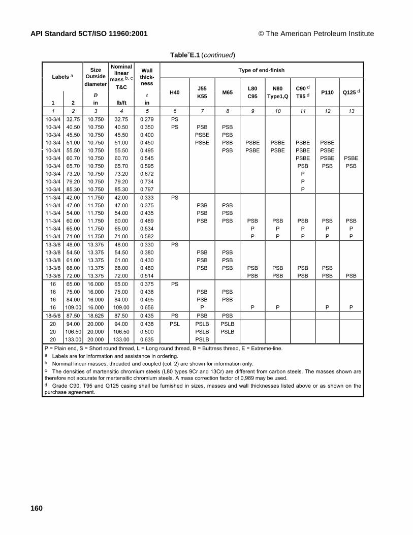
API Standard 5CT/ISO 11960:2001 © The American Petroleum Institute
160
Table E.1 (continued )
Type of end-finishLabels a
SizeOutsidediameter
Nominallinear
mass b, c
T&C
Wallthick-ness
1 2D
in lb/ftt
in
H40J55K55
M65L80C95
N80Type1,Q
C90 d
T95 d P110 Q125 d
1 2 3 4 5 6 7 8 9 10 11 12 13
10-3/410-3/410-3/410-3/410-3/410-3/410-3/410-3/410-3/410-3/4
32.7540.5045.5051.0055.5060.7065.7073.2079.2085.30
10.75010.75010.75010.75010.75010.75010.75010.75010.75010.750
32.7540.5045.5051.0055.5060.7065.7073.2079.2085.30
0.2790.3500.4000.4500.4950.5450.5950.6720.7340.797
PSPS PSB
PSBEPSBE
PSBPSBPSBPSB
PSBEPSBE
PSBEPSBE
PSBEPSBEPSBEPSB
PPP
PSBEPSBEPSBEPSB
PSBEPSB
11-3/411-3/411-3/411-3/411-3/411-3/4
42.0047.0054.0060.0065.0071.00
11.75011.75011.75011.75011.75011.750
42.0047.0054.0060.0065.0071.00
0.3330.3750.4350.4890.5340.582
PSPSBPSBPSB
PSBPSBPSB PSB
PP
PSBPP
PSBPP
PSBPP
PSBPP
13-3/813-3/813-3/813-3/813-3/8
48.0054.5061.0068.0072.00
13.37513.37513.37513.37513.375
48.0054.5061.0068.0072.00
0.3300.3800.4300.4800.514
PSPSBPSBPSB
PSBPSBPSB PSB
PSBPSBPSB
PSBPSB
PSBPSB PSB
16161616
65.0075.0084.00109.00
16.00016.00016.00016.000
65.0075.0084.00109.00
0.3750.4380.4950.656
PSPSBPSB
P
PSBPSB
P P P P
18-5/8 87.50 18.625 87.50 0.435 PS PSB PSB
202020
94.00106.50133.00
20.00020.00020.000
94.00106.50133.00
0.4380.5000.635
PSL PSLBPSLBPSLB
PSLBPSLB
P = Plain end, S = Short round thread, L = Long round thread, B = Buttress thread, E = Extreme-line.a Labels are for information and assistance in ordering.b Nominal linear masses, threaded and coupled (col. 2) are shown for information only.c The densities of martensitic chromium steels (L80 types 9Cr and 13Cr) are different from carbon steels. The masses shown aretherefore not accurate for martensitic chromium steels. A mass correction factor of 0,989 may be used.d Grade C90, T95 and Q125 casing shall be furnished in sizes, masses and wall thicknesses listed above or as shown on thepurchase agreement.

© The American Petroleum Institute API Standard 5CT/ISO 11960:2001
161
Table E.2—ISO/API plain-end casing liner list—Grade J55
LabelsSize
Outside diameterD
Plain-endlinear mass
Wallthickness
t
1 2 in lb/ft in
3-1/2 9.91 3.500 9.91 0.289
4 11.34 4.000 11.34 0.286
4-1/2 13.04 4.500 13.04 0.290
5 17.93 5.000 17.93 0.362
5-1/2 19.81 5.500 19.81 0.361
6-5/8 27.65 6.625 27.65 0.417

API Standard 5CT/ISO 11960:2001 © The American Petroleum Institute
162
Table E.3—ISO/API tubing list
Sizes, masses, wall thickness, grade and applicable end-finish
LabelsNominal linear
masses a, b
Outsidediameter
D
Non-upsetT&C
Ext.upsetT&C
Integ.joint
Wallthick-ness
t
Type of end-finish c
1 2
NUT&C
EUT&C
IJin lb/ft lb/ft lb/ft in
H40 J55 L80 N80Type1,Q
C90 d T95 d P110
1 2 3 4 5 6 7 8 9 10 11 12 13 14 15 16
1.0501.050
1.141.48
1.201.54
1.0501.050
1.141.48
1.201.54
0.1130.154
PNUPU
PNUPU
PNUPU
PNUPU
PNUPU
PNUPU PU
1.3151.315
1.702.19
1.802.24
1.72 1.3151.315
1.702.19
1.802.24
1.72 0.1330.179
PNUIPU
PNUIPU
PNUIPU
PNUIPU
PNUIPU
PNUIPU PU
1.6601.6601.660
2.092.303.03
2.403.07
2.102.33
1.6601.6601.660
2.303.03
2.403.07
2.102.33
0.1250.1400.191
PIPNUIPU
PIPNUIPU
PNUIPU
PNUIPU
PNUIPU
PNUIPU PU
1.9001.9001.9001.9001.900
2.402.753.654.425.15
2.903.73
2.402.76
1.9001.9001.9001.9001.900
2.753.654.425.15
2.903.73
2.402.76
0.1250.1450.2000.2500.300
PIPNUIPU
PIPNUIPU
PNUIPUPP
PNUIPU
PNU IPUPP
PNUIPUPP
PU
2.0632.063
3.244.50
3.25 2.0632.063 4.50
3.25 0.1560.225
PIP
PIP
PIP
PIP
PIP
PIP P
2-3/82-3/82-3/82-3/82-3/8
4.004.605.806.607.35
4.705.95
7.45
2.3752.3752.3752.3752.375
4.004.605.806.607.35
4.705.95
7.45
0.1670.1900.2540.2950.336
PNPNU
PNPNU
PNPNUPNU
PPU
PNPNUPNU
PNPNUPNU
PPU
PNPNUPNU
PPU
PNUPNU
2-7/82-7/82-7/82-7/82-7/82-7/8
6.407.808.609.3510.5011.50
6.507.908.709.45
2.8752.8752.8752.8752.8752.875
6.407.808.609.35
10.5011.50
6.507.908.709.45
-
0.2170.2760.3080.3400.3920.440
PNU PNU PNUPNUPNUPUPP
PNUPNUPNU
PNUPNUPNUPUPP
PNUPNUPNUPUPP
PNUPNUPNU
3-1/23-1/23-1/23-1/23-1/23-1/23-1/2
7.709.2010.2012.7014.3015.5017.00
9.30
12.95
3.5003.5003.5003.5003.5003.5003.500
7.709.20
10.2012.7014.3015.5017.00
9.30
12.95
0.2160.2540.2890.3750.4300.4760.530
PNPNUPN
PNPNUPN
PNPNUPN
PNUPPP
PNPNUPN
PNU
PNPNUPN
PNUPPP
PNPNUPN
PNUPPP
PNU
PNU
444444
9.5010.7013.2016.1018.9022.20
11.004.0004.0004.0004.0004.0004.000
9.50
13.2016.1018.9022.20
11.000.2260.2620.3300.4150.5000.610
PNPU
PNPU
PNPUPPPP
PNPU
PNPUPPPP
PNPUPPPP
4-1/24-1/24-1/24-1/24-1/24-1/24-1/2
12.6015.2017.0018.9021.5023.7026.10
12.75 4.5004.5004.5004.5004.5004.5004.500
12.6015.2017.0018.9021.5023.7026.10
12.75 0.2710.3370.3800.4300.5000.5600.630
PNU PNU PNUPPPPPP
PNU PNUPPPPPP
PNUPPPPPP
P = Plain end, N = Non-upset threaded and coupled, U = External upset threaded and coupled, I = Integral joint.a Nominal linear masses, threads and coupling (col. 2, 3, 4) are shown for information only.b The densities of martensitic chromium steels (L80 types 9Cr and 13Cr) are different from carbon steels. The masses shown are thereforenot accurate for martensitic chromium steels. A mass correction factor of 0,989 may be used.c Non-upset tubing is available with regular couplings or special bevel couplings. External-upset tubing is available with regular, special-bevel, or special-clearance couplings.d Grade C90 and T95 tubing shall be furnished in sizes, masses, and wall thicknesses as listed above, or as shown on the purchaseagreement.

© The American Petroleum Institute API Standard 5CT/ISO 11960:2001
163
Table E.4—Process of manufacture and heat treatment
Group Grade Type Manufacturing process a Heat treatmentTempering temperature
min.
°F1 2 3 4 5 61 H40
J55K55N80N80
1Q
S or EWS or EWS or EWS or EWS or EW
NoneNone b
None bc
Q&T2 M65
L80L80L80C90C90C95T95T95
19Cr
13Cr12
12
S or EWS or EW
SSSS
S or EWSS
d
Q&TQ&T e
Q&T e
Q&TQ&TQ&TQ&TQ&T
10501100110011501150100012001200
3 P110 S or EW f,g Q&T4 Q125
Q125Q125Q125
1234
S or EW g
S or EW g
S or EW g
S or EW g
Q&TQ&TQ&TQ&T
a S = seamless process; EW = electric-welded process.b Full length normalized (N), normalized and tempered (N&T), or quenched and tempered (Q&T), at the manufacturer’s option or asspecified on the purchase agreement.c Full length normalized or normalized and tempered at the manufacturer’s option.d All pipe shall be full body heat-treated. Full length normalized (N), normalized and tempered (N&T), or quenched and tempered(Q&T), at the manufacturer’s option or as specified on the purchase agreement.e Type 9Cr and 13Cr may be air-quenched.f Special chemical requirements for electric-welded P110 casing are specified in Table E.5.g Special requirements unique to electric-welded P110 and Q125 are specified in A.5 (SR11).
Table E.5—Chemical composition, mass fraction (%)
Group Grade Type C Mn Mo Cr Ni Cu P S Simin. max. min. max. min. max. min. max. max. max. max. max. max.
1 2 3 4 5 6 7 8 9 10 11 12 13 14 15 16
H40 0.030 0.030J55 0.030 0.030K55 0.030 0.030N80 1 0.030 0.030
1
N80 Q 0.030 0.030M65 0.030 0.030L80 1 0.43 a 1.90 0.25 0.35 0.030 0.030 0.45L80 9Cr 0.15 0.30 0.60 0.90 1.10 8.00 10.0 0.50 0.25 0.020 0.010 1.00L80 13Cr 0.15 0.22 0.25 1.00 12.0 14.0 0.50 0.25 0.020 0.010 1.00C90 1 0.35 1.00 0.25 b 0.75 1.20 0.99 0.020 0.010C90 2 0.50 1.90 NL NL 0.99 0.030 0.010C95 0.45 c 1.90 0.030 0.030 0.45T95 1 0.35 1.20 0.25 d 0.85 0.40 1.50 0.99 0.020 0.010
2
T95 2 0.50 1.90 0.99 0.030 0.0103 P110 e 0.030 e 0.030 e
Q125 1 0.35 1.00 0.75 1.20 0.99 0.020 0.010Q125 2 0.35 1.00 NL NL 0.99 0.020 0.020Q125 3 0.50 1.90 NL NL 0.99 0.030 0.010
4
Q125 4 0.50 1.90 NL NL 0.99 0.030 0.020a The carbon content for L80 may be increased up to 0.50˚% max. if the product is oil-quenched.b The molybdenum content for Grade C90 Type 1 has no minimum tolerance if the wall thickness is less than 0.700 in.c The carbon content for C95 may be increased up to 0.55˚% max. if the product is oil-quenched.d The molybdenum content for T95 Type 1 may be decreased to 0.15˚% min. if the wall thickness is less than 0.700 in.NL = no limit. Elements shown shall be reported in product analysis.e For EW Grade P110, the phosphorus content shall be 0.020˚% max. and the sulfur content 0.010˚% max.

API Standard 5CT/ISO 11960:2001 © The American Petroleum Institute
164
Table E.6—Tensile and hardness requirements
Group Grade TypeTotal
elongationunder load
Yieldstrength
ksi
Tensilestrength
min.Hardness a
max.Specified wall
thickness
Allowablehardnessvariation b
% min. max. ksi HRC HBW/HBS in HRC
1 2 3 4 5 6 7 8 9 10 11
1 H40
J55
K55
N80N80
1Q
0.5
0.5
0.5
0.50.5
40
55
55
8080
80
80
80
110110
60
75
95
100100
2 M65
L80L80L80
C90C90C90C90
C95
T95T95T95T95
19Cr
13Cr
1, 21, 21, 21, 2
1, 21, 21, 21, 2
0.5
0.50.50.5
0.50.50.50.5
0.5
0.50.50.50.5
65
808080
90909090
95
95959595
85
959595
105105105105
110
110110110110
85
959595
100100100100
105
105105105105
22
232323
25.425.425.425.4
25.425.425.425.4
235
241241241
255255255255
255255255255
² 0.5000.501 to 0.7490.750 to 0.999
³ 1.000
² 0.5000.500 to 0.7490.750 to 0.999
³ 1.000
3.04.05.06.0
3.04.05.06.0
3 P110 0.6 110 140 125
4 Q125Q125Q125
0.650.650.65
125125125
150150150
135135135
b
b
b
² 0.5000.500 to 0.749
³ 0.750
3.04.05.0
a In case of dispute, laboratory Rockwell C hardness testing shall be used as the referee method.b No hardness limits are specified, but the maximum variation is restricted as a manufacturing control in accordance with7.8 and 7.9

© The American Petroleum Institute API Standard 5CT/ISO 11960:2001
165
Table E.7—Elongation table
Minimum elongation in 2.0 in, %
GradeTensile test specimen H40 J55 M65 K55
L80N80-1N80QC90
C95T95
P110 Q125
Specified wall thicknessin
Specified minimum tensile strengthksi
60 75 85 95 100 105 125 135Specimenareain2
Specimenwidth3/4 in
Specimenwidth1 in
Specimenwidth
1-1/2 in
1 2 3 4 5 6 7 8 9 10 11 12
0.750 ³ 0.994 ³ 0.746 ³ 0.497 30 24 22 20 19 18 15 140.740 0.980-0.993 0.735-0.745 0.490-0.496 29 24 22 19 19 18 15 140.730 0.967-0.979 0.726-0.734 0.484-0.489 29 24 21 19 19 18 15 140.720 0.954-0.966 0.715-0.725 0.477-0.483 29 24 21 19 19 18 15 140.710 0.941-0.953 0.706-0.714 0.471-0.476 29 24 21 19 18 18 15 140.700 0.927-0.940 0.695-0.705 0.464-0.470 29 24 21 19 18 18 15 140.690 0.914-0.926 0.686-0.694 0.457-0.463 29 24 21 19 18 18 15 140.680 0.900-0.913 0.675-0.685 0.450-0.456 29 24 21 19 18 18 15 140.670 0.887-0.899 0.666-0.674 0.444-0.449 29 24 21 19 18 17 15 140.660 0.874-0.886 0.655-0.665 0.437-0.443 29 24 21 19 18 17 15 140.650 0.861-0.873 0.646-0.654 0.431-0.436 29 23 21 19 18 17 15 140.640 0.847-0.860 0.635-0.645 0.424-0.430 29 23 21 19 18 17 15 140.630 0.834-0.846 0.626-0.634 0.417-0.423 29 23 21 19 18 17 15 140.620 0.820-0.833 0.615-0.625 0.410-0.416 28 23 21 19 18 17 15 140.610 0.807-0.819 0.606-0.614 0.404-0.409 28 23 21 19 18 17 15 140.600 0.794-0.806 0.595-0.605 0.397-0.403 28 23 21 19 18 17 15 140.590 0.781-0.793 0.586-0.594 0.391-0.396 28 23 21 19 18 17 15 140.580 0.767-0.780 0.575-0.585 0.384-0.390 28 23 21 19 18 17 14 140.570 0.754-0.766 0.566-0.574 0.377-0.383 28 23 20 18 18 17 14 130.560 0.740-0.753 0.555-0.565 0.370-0.376 28 23 20 18 18 17 14 130.550 0.727-0.739 0.546-0.554 0.364-0.369 28 23 20 18 18 17 14 130.540 0.714-0.726 0.535-0.545 0.357-0.363 28 23 20 18 17 17 14 130.530 0.701-0.713 0.526-0.534 0.351-0.356 28 23 20 18 17 17 14 130.520 0.687-0.700 0.515-0.525 0.344-0.350 27 22 20 18 17 17 14 130.510 0.674-0.686 0.506-0.514 0.337-0.343 27 22 20 18 17 17 14 130.500 0.660-0.673 0.495-0.505 0.330-0.336 27 22 20 18 17 16 14 130.490 0.647-0.659 0.486-0.494 0.324-0.329 27 22 20 18 17 16 14 130.480 0.634-0.646 0.475-0.485 0.317-0.323 27 22 20 18 17 16 14 130.470 0.621-0.633 0.466-0.474 0.311-0.316 27 22 20 18 17 16 14 130.460 0.607-0.620 0.455-0.465 0.304-0.310 27 22 20 18 17 16 14 130.450 0.594-0.606 0.446-0.454 0.297-0.303 27 22 20 18 17 16 14 130.440 0.580-0.593 0.435-0.445 0.290-0.296 27 22 19 18 17 16 14 130.430 0.567-0.579 0.426-0.434 0.284-0.289 26 22 19 17 17 16 14 130.420 0.554-0.566 0.415-0.425 0.277-0.283 26 22 19 17 17 16 14 130.410 0.541-0.553 0.406-0.414 0.271-0.276 26 21 19 17 17 16 14 130.400 0.527-0.540 0.395-0.405 0.264-0.270 26 21 19 17 16 16 13 130.390 0.514-0.526 0.386-0.394 0.257-0.263 26 21 19 17 16 16 13 120.380 0.500-0.513 0.375-0.385 0.250-0.256 26 21 19 17 16 16 13 120.370 0.487-0.499 0.366-0.374 0.244-0.249 26 21 19 17 16 16 13 120.360 0.474-0.486 0.355-0.365 0.237-0.243 26 21 19 17 16 15 13 120.350 0.461-0.473 0.346-0.354 0.231-0.236 25 21 19 17 16 15 13 120.340 0.447-0.460 0.335-0.345 0.224-0.230 25 21 18 17 16 15 13 120.330 0.434-0.446 0.326-0.334 0.217-0.223 25 21 18 17 16 15 13 120.320 0.420-0.433 0.315-0.325 0.210-0.216 25 20 18 16 16 15 13 120.310 0.407-0.419 0.306-0.314 0.204-0.209 25 20 18 16 16 15 13 120.300 0.394-0.406 0.295-0.305 0.197-0.203 25 20 18 16 16 15 13 12

API Standard 5CT/ISO 11960:2001 © The American Petroleum Institute
166
Table E.7 (Continued )
Minimum elongation in 2.0 in, %
GradeTensile test specimen H40 J55 M65 K55
L80N80-1N80QC90
C95T95
P110 Q125
Specified wall thicknessin
Specified minimum tensile strengthksi
60 75 85 95 100 105 125 135Specimenareain2
Specimenwidth3/4 in
Specimenwidth1 in
Specimenwidth
1-1/2 in
1 2 3 4 5 6 7 8 9 10 11 12
0.290 0.381-0.393 0.286-0.294 0.191-0.196 24 20 18 16 15 15 13 120.280 0.367-0.380 0.275-0.285 0.184-0.190 24 20 18 16 15 15 13 120.270 0.354-0.366 0.266-0.274 0.177-0.183 24 20 18 16 15 15 12 120.260 0.340-0.353 0.255-0.265 0.170-0.176 24 20 17 16 15 14 12 120.250 0.327-0.339 0.246-0.254 0.164-0.169 24 19 17 16 15 14 12 11
0.240 0.314-0.326 0.235-0.245 0.157-0.163 24 19 17 16 15 14 12 110.230 0.301-0.313 0.226-0.234 0.151-0.156 23 19 17 15 15 14 12 110.220 0.287-0.300 0.215-0.225 0.144-0.150 23 19 17 15 15 14 12 110.210 0.274-0.286 0.206-0.214 0.137-0.143 23 19 17 15 14 14 12 110.200 0.260-0.273 0.195-0.205 0.130-0.136 23 19 17 15 14 14 12 11
0.190 0.247-0.259 0.186-0.194 0.124-0.129 22 18 16 15 14 14 12 110.180 0.234-0.246 0.175-0.185 0.117-0.123 22 18 16 15 14 13 11 110.170 0.221-0.233 0.166-0.174 0.111-0.116 22 18 16 15 14 13 11 110.160 0.207-0.220 0.155-0.165 0.104-0.110 22 18 16 14 14 13 11 100.150 0.194-0.206 0.146-0.154 0.097-0.103 21 18 16 14 14 13 11 10
0.140 0.180-0.193 0.135-0.145 0.090-0.096 21 17 15 14 13 13 11 100.130 0.167-0.179 0.126-0.134 0.084-0.089 21 17 15 14 13 13 11 100.120 0.154-0.166 0.115-0.125 0.077-0.083 20 17 15 14 13 12 11 100.110 0.141-0.153 0.106-0.114 0.071-0.076 20 16 15 13 13 12 10 9.50.100 0.127-0.140 0.095-0.105 0.064-0.070 20 16 14 13 12 12 10 9.5
0.090 0.114-0.126 0.086-0.094 0.057-0.063 19 16 14 13 12 12 10 9.50.080 0.100-0.113 0.075-0.085 0.050-0.056 19 15 14 12 12 11 10 9

© The American Petroleum Institute API Standard 5CT/ISO 11960:2001
167
Table E.8—Critical thickness for couplings with ISO/API threadsDimensions in inches
Critical thickness for couplings
Special-clearanceLabel 1
NU EU EU BC BC LC STC
1 2 3 4 5 6 7 8
1.0501.3151.6601.9002-3/82-7/83-1/2
44-1/2
55-1/26-5/8
77-5/88-5/89-5/8
10-3/411-3/413-3/8
1618-5/8
20
0.1690.2110.2390.1960.3040.3800.4510.4540.435
0.2110.2580.2400.2510.3000.3580.4540.4580.493
0.2240.2540.294
0.2590.2660.2680.2740.2800.3480.3520.3520.352
0.3220.3600.3560.4690.4200.5360.6020.6020.6020.6020.6020.6670.8540.667
0.3490.3920.3890.5080.4580.5730.6470.657
0.673
0.3370.3720.3700.4850.4300.5460.6120.6140.6180.6180.6180.6320.8190.634
NOTE The coupling blank thickness is greater than indicated above, due to thread height and manufacturing allowance toavoid black crest threads.
Table E.9—Acceptable size impact specimens and absorbed energy reduction factor
Test specimen sizeSpecimen dimensions
mmReduction factor
Full size
3/4-size
1/2-size
10.0 ´ 10.0
10.0 ´ 7.5
10.0 ´ 5.0
1.00
0.80
0.55
Table E.10 — Hierarchy of test specimen orientation and size
Choice Orientation Size
1st
2nd
3rd
4th
5th
6th
Transverse
Transverse
Transverse
Longitudinal
Longitudinal
Longitudinal
Full size
3/4-size
1/2-size
Full size
3/4-size
1/2-size

API Standard 5CT/ISO 11960:2001 © The American Petroleum Institute
168
Table E.11—Charpy impact test specimen requirements for couplings Grades J55 and K55
Orientation, size, energy and temperature reduction (see Note)
Special-clearance bLabel 1
NU EU EU BC BC LC STC
1 2 3 4 5 6 7 8
1.0501.3151.6601.9002-3/82-7/83-1/2
44-1/2
55-1/26-5/8
77-5/88-5/89-5/810-3/411-3/413-3/8
1618-5/8
20
a
L-5-11 AL-5-11-BL-5-11-AL-7-16-A
L-10-20-AT-5-8-ET-7-12-BT-7-12-B
L-5-11-AL-7-16-AL-5-11-BL-7-16-BL-7-16-AL-10-20-AT-5-8-ET-7-12-BT-7-12-B
L-7-16-AL-10-20-AT-5-8-D
L-7-16-AT-5-8-CT-5-8-C
T-10-15-AT-7-12-AT-10-15-AT-10-15-AT-10-15-AT-10-15-A
L-7-16-AT-5-8-DT-5-8-D
T-10-15-AT-7-12-A
T-10-15-AT-10-15-AT-10-15-AT-10-15-AT-10-15-AT-10-15-AT-10-15-AT-10-15-AT-10-15-A
L-10-20-AT-5-8-DT-5-8-D
T-10-15-AT-10-15-AT-10-15-AT-10-15-AT-10-15-A
T-10-15-A
L-10-20-AT-5-8-DT-5-8-D
T-10-15-AT-7-12-B
T-10-15-AT-10-15-AT-10-15-AT-10-15-AT-10-15-AT-10-15-AT-10-15-AT-10-15-AT-10-15-A
NOTE In this table, the specimen orientation (T or L) is followed by the minimum specimen size (10, 7 or 5) which is followed bythe minimum absorbed energy requirement (foot pounds) and the temperature reduction (A, B, C, D or E), according to the followingcode. Both the absorbed energy requirement and the test temperature reduction requirement are adjusted for the test specimen sizeindicated.
T is the transverse specimen orientation (reference Figure D.12)L is the longitudinal specimen orientation (reference Figure D.12)10 = full size (i.e., 10 mm ´ 10 mm)7 = 3/4-size (i.e., 10 mm ´ 7.5 mm)5 = 1/2-size (i.e., 10 mm ´ 5 mm)A = no temperature reductionB = 5°F reductionC = 10°F reductionD = 15°F reductionE = 20°F reduction
a Not thick enough to test.b The above assumes that special-clearance couplings are machined from standard couplings.

© The American Petroleum Institute API Standard 5CT/ISO 11960:2001
169
Table E.12—Charpy impact test specimen requirements for couplings Grade L80 all types
Orientation, size, energy (see Note)
Special-clearance bLabel 1
NU EU EU BC BC LC STC
1 2 3 4 5 6 7 8
1.0501.3151.6601.9002-3/82-7/83-1/2
44-1/2
55-1/26-5/8
77-5/88-5/89-5/810-3/411-3/413-3/8
1618-5/8
20
a
L-5-16L-5-16L-5-16L-7-24L-10-30T-5-8T-7-12T-7-12
L-5-16L-7-24L-5-16L-7-24L-7-24
L-10-30T-5-8T-7-12T-7-12
L-7-24L-10-30T-5-8
L-7-24T-5-8T-5-8
T-10-15T-7-12
T-10-15T-10-15T-10-15T-10-15
L-7-24T-5-8T-5-8
T-10-15T-7-12T-10-15T-10-15T-10-15T-10-15T-10-15T-10-15T-10-16T-10-18T-10-16
L-10-30T-5-8T-5-8
T-10-15T-10-15T-10-15T-10-15T-10-16
T-10-16
T-10-15T-10-15T-10-15T-10-15T-10-18T-10-15
NOTE In this table, the specimen orientation (T or L) is followed by the minimum specimen size (10, 7 or 5) which is followed bythe minimum absorbed energy requirement (foot pounds) according to the following code. The absorbed energy requirement isadjusted for the test specimen size indicated.
T is the transverse specimen orientation (reference Figure D.12)L is the longitudinal specimen orientation (reference Figure D.12)10 = full size (i.e., 10 mm ´ 10 mm)7 = 3/4-size (i.e., 10 mm ´ 7.5 mm)5 = 1/2-size (i.e., 10 mm ´ 5 mm)
a Not thick enough to test.b The above assumes that special-clearance couplings are machined from standard couplings.

API Standard 5CT/ISO 11960:2001 © The American Petroleum Institute
170
Table E.13—Charpy impact test specimen requirements for couplings Grade C90
Orientation, size and energy (see Note)
Special-clearance bLabel 1
NU EU EU BC BC LC STC
1 2 3 4 5 6 7 8
1.0501.3151.6601.9002-3/82-7/83-1/2
44-1/2
55-1/26-5/8
77-5/88-5/89-5/810-3/411-3/413-3/8
1618-5/8
20
a
L-5-16L-5-16L-5-16L-7-24L-10-30T-5-8T-7-12T-7-12
L-5-16L-7-24L-5-16L-7-24L-7-24
L-10-30T-5-8T-7-12T-7-12
L-7-24L-10-30T-5-8
L-7-24T-5-8T-5-8
T-10-15T-7-12
T-10-15T-10-15T-10-15T-10-15
L-7-24T-5-8T-5-8
T-10-15T-7-12T-10-15T-10-16T-10-16T-10-16T-10-16T-10-16
L-10-30T-5-8T-5-8
T-10-15T-10-15T-10-16T-10-17T-10-17 ---
T-10-17T-10-17T-10-17
NOTE In this table, the specimen orientation (T or L) is followed by the minimum specimen size (10, 7 or 5) which is followed bythe minimum absorbed energy requirement (foot pounds) according to the following code. The absorbed energy requirement isadjusted for the test specimen size indicated.
T is the transverse specimen orientation (reference Figure D.12)L is the longitudinal specimen orientation (reference Figure D.12)10 = full size (i.e., 10 mm ´ 10 mm)7 = 3/4-size (i.e., 10 mm ´ 7.5 mm)5 = 1/2-size (i.e., 10 mm ´ 5 mm)
a Not thick enough to test.b The above assumes that special-clearance couplings are machined from standard couplings.

© The American Petroleum Institute API Standard 5CT/ISO 11960:2001
171
Table E.14—Charpy impact test specimen requirements for couplings—Grades N80 Type 1, N80Q, C95 and T95
Orientation, size and energy (see Note)
Special-clearance bLabel 1
NU EU EU BC BC LC STC
1 2 3 4 5 6 7 8
1.050
1.315
1.660
1.900
2-3/8
2-7/8
3-1/2
4
4-1/2
5
5-1/2
6-5/8
7
7-5/8
8-5/8
9-5/8
10-3/4
11-3/4
13-3/8
16
18-5/8
20
a
L-5-16
L-5-16
L-5-16
L-7-24
L-10-30
T-5-8
T-7-12
T-7-12
Ñ
Ñ
Ñ
Ñ
Ñ
Ñ
Ñ
Ñ
Ñ
Ñ
Ñ
Ñ
Ñ
L-5-16
L-7-24
L-5-16
L-7-24
L-7-24
L-10-30
T-5-8
T-7-12
T-10-15
Ñ
Ñ
Ñ
Ñ
Ñ
Ñ
Ñ
Ñ
Ñ
Ñ
Ñ
Ñ
Ñ
Ñ
Ñ
Ñ
Ñ
L-7-24
L-10-30
T-5-8
Ñ
Ñ
Ñ
Ñ
Ñ
Ñ
Ñ
Ñ
Ñ
Ñ
Ñ
Ñ
Ñ
Ñ
Ñ
Ñ
Ñ
Ñ
Ñ
Ñ
Ñ
Ñ
Ñ
L-7-24
T-5-8
T-5-8
T-10-15
T-7-12
T-10-15
T-10-15
T-10-15
T-10-15
Ñ
Ñ
Ñ
Ñ
Ñ
Ñ
Ñ
Ñ
Ñ
Ñ
Ñ
Ñ
Ñ
L-7-24
T-5-8
T-5-8
T-10-15
T-7-12
T-10-16
T-10-17
T-10-17
T-10-17
T-10-17
T-10-17
Ñ
Ñ
Ñ
Ñ
Ñ
Ñ
Ñ
Ñ
Ñ
Ñ
Ñ
L-10-30
T-5-8
T-5-8
T-10-16
T-10-15
T-10-17
T-10-18
T-10-18
Ñ
Ñ
Ñ
Ñ
Ñ
Ñ
Ñ
Ñ
Ñ
Ñ
Ñ
Ñ
Ñ
Ñ
Ñ
Ñ
Ñ
Ñ
Ñ
Ñ
Ñ
Ñ
T-10-17
T-10-17
T-10-17
Ñ
Ñ
Ñ
NOTE In this table, the specimen orientation (T or L) is followed by the minimum specimen size (10, 7 or 5) which is followed by theminimum absorbed energy requirement (foot pounds) according to the following code. The absorbed energy requirement is adjusted forthe test specimen size indicated.
T is the transverse specimen orientation (reference Figure D.12)
L is the longitudinal specimen orientation (reference Figure D.12)
10 = full size (i.e., 10 mm ´ 10 mm)
7 = 3/4-size (i.e., 10 mm ´ 7.5 mm)
5 = 1/2-size (i.e., 10 mm ´ 5 mm)a Not thick enough to test.b The above assumes that special-clearance couplings are machined from standard couplings.

API Standard 5CT/ISO 11960:2001 © The American Petroleum Institute
172
Table E.15—Charpy impact test specimen requirements for couplings Grade P110
Orientation, size and energy (see Note)
Special-clearance bLabel 1
NU EU EU BC BC LC STC
1 2 3 4 5 6 7 81.0501.3151.6601.9002-3/82-7/83-1/2
44-1/2
55-1/26-5/8
77-5/88-5/89-5/810-3/411-3/413-3/8
1618-5/8
20
a
L-5-16L-5-16L-5-16L-7-25L-10-34T-5-10T-7-15T-7-14
ÑÑÑÑÑÑÑÑÑÑÑÑÑ
L-5-16L-7-24L-5-16L-7-24L-7-25
L-10-33T-5-10T-7-15T-7-15
ÑÑÑÑÑÑÑÑÑÑÑÑÑ
ÑÑÑÑ
L-7-24L-10-30T-5-8
ÑÑÑÑÑÑÑÑÑÑÑÑÑÑÑ
ÑÑÑÑÑÑÑÑ
L-7-24T-5-8T-5-8
T-10-15T-7-12T-10-16T-10-16T-10-16T-10-16
ÑÑÑÑÑ
ÑÑÑÑÑÑÑÑ
L-7-26T-5-9T-5-9
T-10-19T-7-14
T-10-20T-10-22T-10-22T-10-22T-10-22T-10-22
ÑÑÑ
-ÑÑÑÑÑÑÑÑ
L-10-33T-5-9T-5-9
T-10-20T-10-19T-10-21T-10-23T-10-23
ÑÑÑÑÑÑ
ÑÑÑÑÑÑÑÑÑÑÑÑÑÑÑÑ
T-10-22T-10-22T-10-22
ÑÑÑ
NOTE In this table, the specimen orientation (T or L) is followed by the minimum specimen size (10, 7 or 5) which is followed by theminimum absorbed energy requirement (foot pounds) according to the following code. The absorbed energy requirement is adjusted forthe test specimen size indicated.
T is the transverse specimen orientation (reference Figure D.12)
L is the longitudinal specimen orientation (reference Figure D.12)
10 = full size (i.e., 10 mm ´ 10 mm)
7 = 3/4-size (i.e., 10 mm ´ 7.5 mm)
5 = 1/2-size (i.e., 10 mm ´ 5 mm)a Not thick enough to test.b The above assumes that special-clearance couplings are machined from standard couplings.
Table E.16—Charpy impact test specimen requirements for ISO/API couplings Grade Q125
Orientation, size and energy (see Note)
Special-clearance aLabel 1
BC BC LC STC1 2 3 4 5
4-1/25
5-1/26-5/8
77-5/88-5/89-5/810-3/411-3/413-3/8
1618-5/8
20
L-7-25T-5-9T-5-9
T-10-16T-7-13
T-10-18T-10-18T-10-18T-10-18
ÑÑÑÑÑ
L-7-27T-5-10T-5-10T-10-20T-7-15T-10-22T-10-23T-10-23T-10-23T-10-23T-10-23
ÑÑÑ
L-10-35T-5-10T-5-10
T-10-21T-10-19T-10-23T-10-24T-10-25
ÑÑÑÑÑÑ
ÑÑÑÑÑÑÑÑ
T-10-24T-10-24
T-10-24TÑÑÑ
NOTE In this table, the specimen orientation (T or L) is followed by the minimum specimen size (10, 7 or 5) which is followed by theminimum absorbed energy requirement (foot pounds) according to the following code. The absorbed energy requirement is adjusted forthe test specimen size indicated.
T is the transverse specimen orientation (reference Figure D.12)L is the longitudinal specimen orientation (reference Figure D.12)10 = full size (i.e., 10 mm ´ 10 mm)7 = 3/4-size (i.e., 10 mm ´ 7.5 mm)5 = 1/2-size (i.e., 10 mm ´ 5 mm)
a The above assumes that special-clearance couplings are machined from standard couplings.

© The American Petroleum Institute API Standard 5CT/ISO 11960:2001
173
Table E.17—Transverse Charpy absorbed energy requirements for ISO/API couplings
Maximum critical thickness for various gradesin
L80 C90 N80Q, C95, T95 P110 Q125
Minimumtransverse
absorbed energy
ft.lb
1 2 3 4 5 60.652 0.550 0.505 0.307 0.258 150.721 0.612 0.565 0.354 0.302 160.790 0.675 0.625 0.401 0.346 170.860 0.738 0.685 0.448 0.390 180.929 0.800 0.745 0.495 0.434 190.998 0.863 0.805 0.542 0.478 201.067 0.926 0.864 0.589 0.521 21
Ñ 0.988 0.924 0.636 0.565 22Ñ 1.051 0.984 0.683 0.609 23Ñ Ñ 1.044 0.730 0.653 24Ñ Ñ Ñ 0.777 0.697 25Ñ Ñ Ñ 0.824 0.741 26Ñ Ñ Ñ 0.871 0.785 27Ñ Ñ Ñ 0.918 0.828 28Ñ Ñ Ñ 0.965 0.872 29Ñ Ñ Ñ 1.012 0.916 30Ñ Ñ Ñ Ñ 0.960 31Ñ Ñ Ñ Ñ 1.004 32
NOTE 1 Critical thicknesses greater than shown in Table E.8 are not applicable for ISO/API couplings and are shown here forinformation for special applications. For wall thickness greater than shown above, the requirements shall be according to the equationsfor the wall thickness and grade.
NOTE 2 Grade M65 is not mentioned in this table, because it is furnished with L80 couplings.
Table E.18—Longitudinal Charpy absorbed energy requirements for ISO/API couplings
Maximum critical thicknessin
L80 C90 N80Q, C95, T95 P110 Q125
Minimumlongitudinal
absorbed energy
ft.lb
1 2 3 4 5 60.635 0.534 0.491 0.295 0.247 300.669 0.565 0.520 0.319 0.269 310.704 0.597 0.550 0.342 0.291 320.738 0.628 0.580 0.366 0.313 330.773 0.659 0.610 0.389 0.335 340.808 0.691 0.640 0.413 0.357 350.842 0.722 0.670 0.436 0.379 360.877 0.753 0.700 0.460 0.401 370.912 0.785 0.730 0.483 0.423 380.946 0.816 0.760 0.507 0.445 390.981 0.847 0.790 0.530 0.467 401.015 0.879 0.819 0.554 0.489 41
Ñ 0.910 0.849 0.577 0.510 42Ñ 0.941 0.879 0.601 0.532 43Ñ 0.973 0.909 0.624 0.554 44Ñ 1.004 0.939 0.648 0.576 45Ñ Ñ 0.969 0.671 0.598 46Ñ Ñ 0.999 0.695 0.620 47Ñ Ñ 1.029 0.718 0.642 48Ñ Ñ Ñ 0.742 0.664 49Ñ Ñ Ñ 0.765 0.686 50
NOTE 1 Critical thicknesses greater than shown in Table E.8 are not applicable for ISO/API couplings and are shown here forinformation for special applications. For wall thickness greater than shown above, the requirements shall be according to the equationsfor the wall thickness and grade.
NOTE 2 Grade M65 is not mentioned in this table, because it is furnished with L80 couplings.

API Standard 5CT/ISO 11960:2001 © The American Petroleum Institute
174
Table E.19—Transverse Charpy absorbed energy requirements for pipe
Maximum specified wall thicknessin
N80Q, L80 C90 C95, T95 P110 Q125
Minimumtransverse
absorbed energyft.lb
1 2 3 4 5 6
0.442 0.346 0.306 Ñ Ñ 10
0.524 0.419 0.375 Ñ Ñ 11
0.606 0.492 0.444 Ñ Ñ 12
0.689 0.565 0.513 Ñ Ñ 13
0.771 0.638 0.583 Ñ Ñ 14
0.853 0.711 0.652 0.505 0.258 15
0.935 0.785 0.721 0.565 0.302 16
1.018 0.858 0.790 0.625 0.346 17
Ñ 0.931 0.860 0.685 0.390 18
Ñ 1.004 0.929 0.745 0.434 19
Ñ Ñ 0.998 0.805 0.478 20
Ñ Ñ Ñ 0.864 0.521 21
Ñ Ñ Ñ 0.924 0.565 22
Ñ Ñ Ñ 0.984 0.609 23
Ñ Ñ Ñ 1.044 0.653 24
Ñ Ñ Ñ Ñ 0.697 25
Ñ Ñ Ñ Ñ 0.741 26
Ñ Ñ Ñ Ñ 0.785 27
Ñ Ñ Ñ Ñ 0.828 28
Ñ Ñ Ñ Ñ 0.872 29
Ñ Ñ Ñ Ñ 0.916 30
Ñ Ñ Ñ Ñ 0.960 31
Ñ Ñ Ñ Ñ 1.004 32
NOTE Wall thickness greater than standard ISO/API pipe are shown here for information for special applications. For wallthickness greater than shown above, the requirements shall be according to the equations for the wall thickness and grade.

© The American Petroleum Institute API Standard 5CT/ISO 11960:2001
175
Table E.20—Longitudinal Charpy absorbed energy requirements for pipe
Maximum specified wall thicknessin
N80Q, L80 C90 C95, T95 P110 Q125
Minimumlongitudinal
absorbed energy
ft.lb1 2 3 4 5 6
0.421 0.328 0.288 Ñ Ñ 200.462 0.364 0.323 Ñ Ñ 210.504 0.401 0.358 Ñ Ñ 220.545 0.437 0.392 Ñ Ñ 230.586 0.474 0.427 Ñ Ñ 240.627 0.510 0.461 Ñ Ñ 250.668 0.547 0.496 Ñ Ñ 260.709 0.584 0.531 Ñ Ñ 270.750 0.620 0.565 Ñ Ñ 280.791 0.657 0.600 Ñ Ñ 290.833 0.693 0.635 0.491 0.247 300.874 0.730 0.669 0.520 0.269 310.915 0.766 0.704 0.550 0.291 320.956 0.803 0.738 0.580 0.313 330.997 0.839 0.773 0.610 0.335 341.038 0.876 0.808 0.640 0.357 35
Ñ 0.913 0.842 0.670 0.379 36Ñ 0.949 0.877 0.700 0.401 37Ñ 0.986 0.912 0.730 0.423 38Ñ 1.022 0.946 0.760 0.445 39Ñ Ñ 0.981 0.790 0.467 40Ñ Ñ 1.015 0.819 0.489 41Ñ Ñ Ñ 0.849 0.510 42Ñ Ñ Ñ 0.879 0.532 43Ñ Ñ Ñ 0.909 0.554 44Ñ Ñ Ñ 0.939 0.576 45Ñ Ñ Ñ 0.969 0.598 46Ñ Ñ Ñ 0.999 0.620 47Ñ Ñ Ñ 1.029 0.642 48Ñ Ñ Ñ Ñ 0.664 49Ñ Ñ Ñ Ñ 0.686 50
NOTE Wall thickness greater than standard ISO/API pipe are shown here for information for special applications. For wallthickness greater than shown above, the requirements shall be according to the equations for the wall thickness and grade.
Table E.21—Transverse impact specimen size required for pipe in quenched and tempered grades
Calculated wall thickness required to machinetransverse Charpy impact specimens
inLabel 1
Full size 3/4-size 1/2-size1 2 3 4
3-1/24
4-1/25
5-1/26-5/8
77-5/87-3/48-5/89-5/810-3/411-3/413-3/8
1618-5/8
20
0.8090.7520.7120.6810.6560.6160.6060.5910.5880.5720.5570.5440.5350.5220.5080.4970.493
0.7110.6540.6140.5830.5580.5180.5080.4930.4900.4740.4590.4460.4370.4240.4100.3990.395
0.6120.5550.5150.4840.4590.4190.4090.3940.3910.3750.3600.3470.3380.3250.3110.3000.296
NOTE The wall thicknesses in columns 2, 3 and 4 that are in excess of the maximum wall thicknesses are for information only.The above provides a 0.020 in ID and a 0.020 in OD machining allowance.
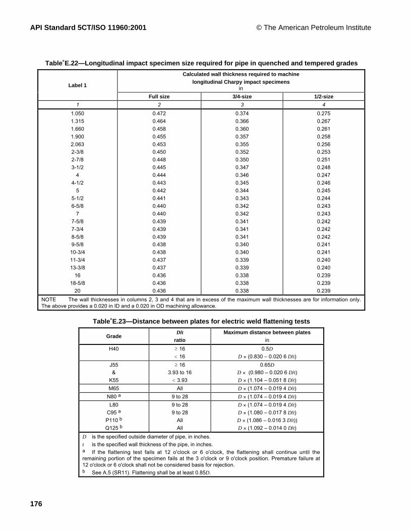
API Standard 5CT/ISO 11960:2001 © The American Petroleum Institute
176
Table E.22—Longitudinal impact specimen size required for pipe in quenched and tempered grades
Calculated wall thickness required to machinelongitudinal Charpy impact specimens
inLabel 1
Full size 3/4-size 1/2-size
1 2 3 4
1.050
1.315
1.660
1.900
2.063
2-3/8
2-7/8
3-1/2
4
4-1/2
5
5-1/2
6-5/8
7
7-5/8
7-3/4
8-5/8
9-5/8
10-3/4
11-3/4
13-3/8
16
18-5/8
20
0.472
0.464
0.458
0.455
0.453
0.450
0.448
0.445
0.444
0.443
0.442
0.441
0.440
0.440
0.439
0.439
0.439
0.438
0.438
0.437
0.437
0.436
0.436
0.436
0.374
0.366
0.360
0.357
0.355
0.352
0.350
0.347
0.346
0.345
0.344
0.343
0.342
0.342
0.341
0.341
0.341
0.340
0.340
0.339
0.339
0.338
0.338
0.338
0.275
0.267
0.261
0.258
0.256
0.253
0.251
0.248
0.247
0.246
0.245
0.244
0.243
0.243
0.242
0.242
0.242
0.241
0.241
0.240
0.240
0.239
0.239
0.239
NOTE The wall thicknesses in columns 2, 3 and 4 that are in excess of the maximum wall thicknesses are for information only.The above provides a 0.020 in ID and a 0.020 in OD machining allowance.
Table E.23—Distance between plates for electric weld flattening tests
GradeD/t
ratioMaximum distance between plates
in
H40 ³ 16
< 16
0.5D
D ´ (0.830 Ð 0.020Ê6 D/t)
J55
&
K55
³ 16
3.93 to 16
< 3.93
0.65D
D ´ (0.980 Ð 0.020Ê6 D/t)D ´ (1.104 Ð 0.051Ê8 D/t)
M65 All D ´ (1.074 Ð 0.019Ê4 D/t)
N80 a 9 to 28 D ´ (1.074 Ð 0.019Ê4 D/t)
L80
C95 a
P110 b
Q125 b
9 to 28
9 to 28
All
All
D ´ (1.074 Ð 0.019Ê4 D/t)D ´ (1.080 Ð 0.017Ê8 D/t)D ´ (1.086 Ð 0.016Ê3 D/t))D ´ (1.092 Ð 0.014Ê0 D/t)
D is the specified outside diameter of pipe, in inches.
t is the specified wall thickness of the pipe, in inches.a If the flattening test fails at 12 o'clock or 6 o'clock, the flattening shall continue until theremaining portion of the specimen fails at the 3 o'clock or 9 o'clock position. Premature failure at12 o'clock or 6 o'clock shall not be considered basis for rejection.b See A.5 (SR11). Flattening shall be at least 0.85D.

© The American Petroleum Institute API Standard 5CT/ISO 11960:2001
177
Table E.24—Dimensions and masses for round thread, buttress thread and extreme-line casing
Calculated mass c
ew, mass gain or loss due to end finishing d
Labels a lb
Outsidediameter
Wallthick-ness
Insidediamet’r
Driftdiamet’r
Plainend Round thread Buttress thread Extreme-line
1 2Din
NominallinearmassT&Cb, c
lb/fttin
din in
Wpe
lb/ftShort Long Reg. OD SCC Stand’d Optional
1 2 3 4 5 6 7 8 9 10 11 12 13 144-1/24-1/24-1/24-1/24-1/2
9.5010.5011.6013.5015.10
4.5004.5004.5004.5004.500
9.5010.5011.6013.5015.10
0.2050.2240.2500.2900.337
4.0904.0524.0003.9203.826
3.9653.9273.8753.7953.701
9.4110.2411.3613.0515.00
4.203.803.40ÑÑ
ÑÑ
3.803.202.80
Ñ5.004.604.003.20
Ñ2.562.161.560.76
ÑÑÑÑÑ
ÑÑÑÑÑ
5555555
11.5013.0015.0018.0021.4023.2024.10
5.0005.0005.0005.0005.0005.0005.000
11.5013.0015.0018.0021.4023.2024.10
0.2200.2530.2960.3620.4370.4780.500
4.5604.4944.4084.2764.1264.0444.000
4.4354.3694.2834.1514.0013.9193.875
11.2412.8414.8817.9521.3223.1124.05
5.404.804.20ÑÑÑÑ
Ñ5.805.204.202.952.301.95
Ñ6.605.804.402.462.051.24
Ñ2.421.620.22-1.72-2.09-2.94
ÑÑ
4.601.40ÑÑÑ
ÑÑÑÑÑÑÑ
5-1/25-1/25-1/25-1/25-1/25-1/25-1/25-1/25-1/25-1/25-1/25-1/2
14.0015.5017.0020.0023.0026.8029.7032.6035.3038.0040.5043.10
5.5005.5005.5005.5005.5005.5005.5005.5005.5005.5005.5005.500
14.0015.5017.0020.0023.0026.8029.7032.6035.3038.0040.5043.10
0.2440.2750.3040.3610.4150.5000.56206250.6870.7500.8120.875
5.0124.9504.8924.7784.6704.5004.3764.2504.1264.0003.8763.750
4.8874.8254.7674.6534.5454.3754.2514.1254.0013.8753.7513.625
13.7115.3616.8919.8322.5626.7229.6732.5735.3538.0840.6943.26
5.404.804.40ÑÑÑÑÑÑÑÑÑ
Ñ5.805.404.403.20ÑÑÑÑÑÑÑ
Ñ6.405.804.603.40ÑÑÑÑÑÑÑ
Ñ2.101.500.30-0.90
ÑÑÑÑÑÑÑ
Ñ5.804.801.400.00ÑÑÑÑÑÑÑ
Ñ4.203.20-0.20-1.60
ÑÑÑÑÑÑÑ
6-5/86-5/86-5/86-5/8
20.0024.0028.0032.00
6.6256.6256.6256.625
20.0024.0028.0032.00
0.2880.3520.4170.475
6.0495.9215.7915.675
5.9245.7965.6665.550
19.5123.6027.6731.23
11.009.60ÑÑ
13.6012.0010.208.80
14.4012.6010.609.00
2.380.58-1.42-3.02
Ñ3.400.20-1.40
Ñ1.80-1.40-3.00
777777777777777
17.0020.0023.0023.0026.0029.0032.0032.0035.0038.0042.7046.4050.1053.6057.10
7.0007.0007.0007.0007.0007.0007.0007.0007.0007.0007.0007.0007.0007.0007.000
17.0020.0023.0023.0026.0029.0032.0032.0035.0038.0042.7046.4050.1053.6057.10
0.2310.2720.3170.3170.3620.4080.4530.4530.4980.5400.6260.6870.7500.8120.875
6.5386.4566.3666.3666.2766.1846.0946.0946.0045.9205.7505.6255.5005.3765.250
6.4136.331
6.250 e
6.2416.1516.059
6.000 e5.9695.8795.7955.6255.5005.3755.2515.125
16.7219.5622.6522.6525.6928.7531.7031.7034.6137.2942.6546.3650.1153.7157.29
10.009.408.008.007.20ÑÑÑÑÑÑÑÑÑÑ
ÑÑ
10.4010.409.408.006.606.605.604.40ÑÑÑÑÑ
ÑÑ
11.0011.009.608.206.806.805.604.20ÑÑÑÑÑ
ÑÑ
1.601.600.20-1.20-2.60-2.60-3.80-5.20
ÑÑÑÑÑ
ÑÑ
6.006.002.800.60-0.60-0.601.00-0.20
ÑÑÑÑÑ
ÑÑ
4.204.201.00-1.20-2.40-2.40-1.80-3.00
ÑÑÑÑÑ
7-5/87-5/87-5/87-5/87-5/87-5/87-5/87-5/87-5/87-5/8
24.0026.2029.7033.7039.0042.8045.3047.1051.2055.30
7.6257.6257.6257.6257.6257.6257.6257.6257.6257.625
24.0026.4029.7033.7039.0042.8045.3047.1051.2055.30
0.3000.3280.3750.4300.5000.5620.5950.6250.6870.750
7.0256.9696.8756.7656.6256.5016.4356.3756.2516.125
6.9006.8446.7506.6406.5006.3766.3106.2506.1266.000
23.4925.5929.0633.0738.0842.4344.7146.7750.9555.12
15.8015.20
ÑÑÑÑÑÑÑÑ
Ñ19.0017.4015.8013.6012.0111.0410.16
ÑÑ
Ñ20.6018.8017.0014.6011.3911.049.23ÑÑ
Ñ6.214.412.610.21-3.01-3.36-5.17
ÑÑ
Ñ6.402.600.00-2.20
ÑÑÑÑÑ
Ñ4.000.20-2.40-4.60
ÑÑÑÑÑ
7-3/47-3/4
46.1046.10
7.7507.750
46.1046.10
0.5950.595
6.5606.560
6.500 e6.435
45.5445.54
ÑÑ
ÑÑ
ÑÑ
ÑÑ
ÑÑ
ÑÑ
8-5/88-5/88-5/88-5/88-5/88-5/88-5/88-5/88-5/8
24.0028.0032.0032.0036.0040.0040.0044.0049.00
8.6258.6258.6258.6258.6258.6258.6258.6258.625
24.0028.0032.0032.0036.0040.0040.0044.0049.00
0.2640.3040.3520.3520.4000.4500.4500.5000.557
8.0978.0177.9217.9217.8257.7257.7257.6257.511
7.9727.892
7.875 e
7.7967.700
7.625 e
7.6007.5007.286
23.6027.0431.1331.1335.1739.3339.3343.4348.04
23.6022.2020.8020.8019.40
ÑÑÑÑ
ÑÑ
27.6027.6025.6023.8023.8021.8019.60
ÑÑ
28.3028.2026.2024.2024.2022.2019.80
ÑÑ
6.036.034.032.032.030.03-2.37
ÑÑ
13.2013.207.604.004.001.60-0.80
ÑÑ
8.808.804.200.600.60-1.80-4.20
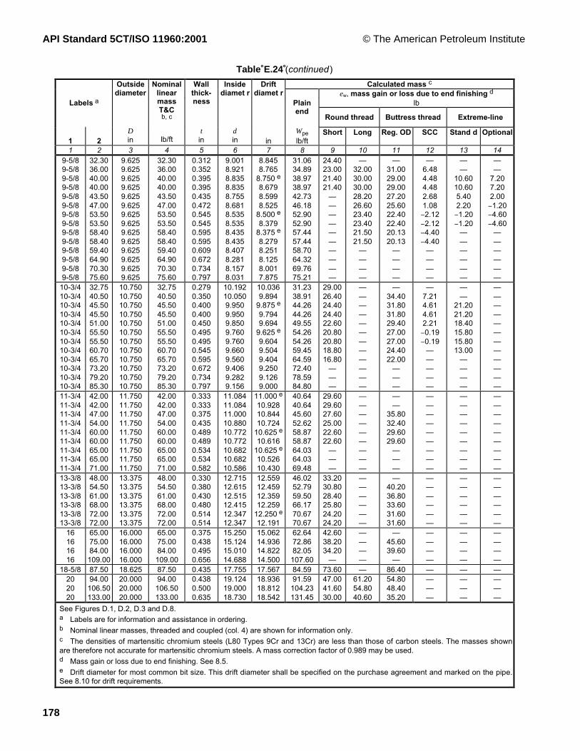
API Standard 5CT/ISO 11960:2001 © The American Petroleum Institute
178
Table E.24 (continued )
Calculated mass c
ew, mass gain or loss due to end finishing d
Labels a lb
Outsidediameter
Wallthick-ness
Insidediamet r
Driftdiamet r
Plainend
Round thread Buttress thread Extreme-line
1 2Din
NominallinearmassT&Cb, c
lb/fttin
din in
Wpe
lb/ftShort Long Reg. OD SCC Stand d Optional
1 2 3 4 5 6 7 8 9 10 11 12 13 149-5/89-5/89-5/89-5/89-5/89-5/89-5/89-5/89-5/89-5/89-5/89-5/89-5/89-5/8
32.3036.0040.0040.0043.5047.0053.5053.5058.4058.4059.4064.9070.3075.60
9.6259.6259.6259.6259.6259.6259.6259.6259.6259.6259.6259.6259.6259.625
32.3036.0040.0040.0043.5047.0053.5053.5058.4058.4059.4064.9070.3075.60
0.3120.3520.3950.3950.4350.4720.5450.5450.5950.5950.6090.6720.7340.797
9.0018.9218.8358.8358.7558.6818.5358.5358.4358.4358.4078.2818.1578.031
8.8458.765
8.750 e
8.6798.5998.525
8.500 e
8.3798.375 e
8.2798.2518.1258.0017.875
31.0634.8938.9738.9742.7346.1852.9052.9057.4457.4458.7064.3269.7675.21
24.4023.0021.4021.40
ÑÑÑÑÑÑÑÑÑÑ
Ñ32.0030.0030.0028.2026.6023.4023.4021.5021.50
ÑÑÑÑ
Ñ31.0029.0029.0027.2025.6022.4022.4020.1320.13
ÑÑÑÑ
Ñ6.484.484.482.681.08-2.12-2.12-4.40-4.40
ÑÑÑÑ
ÑÑ
10.6010.605.402.20-1.20-1.20
ÑÑÑÑÑÑ
ÑÑ
7.207.202.00-1.20-4.60-4.60
ÑÑÑÑÑÑ
10-3/410-3/410-3/410-3/410-3/410-3/410-3/410-3/410-3/410-3/410-3/410-3/4
32.7540.5045.5045.5051.0055.5055.5060.7065.7073.2079.2085.30
10.75010.75010.75010.75010.75010.75010.75010.75010.75010.75010.75010.750
32.7540.5045.5045.5051.0055.5055.5060.7065.7073.2079.2085.30
0.2790.3500.4000.4000.4500.4950.4950.5450.5950.6720.7340.797
10.19210.0509.9509.9509.8509.7609.7609.6609.5609.4069.2829.156
10.0369.894
9.875 e
9.7949.694
9.625 e
9.6049.5049.4049.2509.1269.000
31.2338.9144.2644.2649.5554.2654.2659.4564.5972.4078.5984.80
29.0026.4024.4024.4022.6020.8020.8018.8016.80
ÑÑÑ
ÑÑÑÑÑÑÑÑÑÑÑÑ
Ñ34.4031.8031.8029.4027.0027.0024.4022.00
ÑÑÑ
Ñ7.214.614.612.21-0.19-0.19
ÑÑÑÑÑ
ÑÑ
21.2021.2018.4015.8015.8013.00
ÑÑÑÑ
ÑÑÑÑÑÑÑÑÑÑÑÑ
11-3/411-3/411-3/411-3/411-3/411-3/411-3/411-3/411-3/4
42.0042.0047.0054.0060.0060.0065.0065.0071.00
11.75011.75011.75011.75011.75011.75011.75011.75011.750
42.0042.0047.0054.0060.0060.0065.0065.0071.00
0.3330.3330.3750.4350.4890.4890.5340.5340.582
11.08411.08411.00010.88010.77210.77210.68210.68210.586
11.000 e
10.92810.84410.724
10.625 e
10.61610.625 e
10.52610.430
40.6440.6445.6052.6258.8758.8764.0364.0369.48
29.6029.6027.6025.0022.6022.60
ÑÑÑ
ÑÑÑÑÑÑÑÑÑ
ÑÑ
35.8032.4029.6029.60
ÑÑÑ
ÑÑÑÑÑÑÑÑÑ
ÑÑÑÑÑÑÑÑÑ
ÑÑÑÑÑÑÑÑÑ
13-3/813-3/813-3/813-3/813-3/813-3/8
48.0054.5061.0068.0072.0072.00
13.37513.37513.37513.37513.37513.375
48.0054.5061.0068.0072.0072.00
0.3300.3800.4300.4800.5140.514
12.71512.61512.51512.41512.34712.347
12.55912.45912.35912.259
12.250 e
12.191
46.0252.7959.5066.1770.6770.67
33.2030.8028.4025.8024.2024.20
ÑÑÑÑÑÑ
Ñ40.2036.8033.6031.6031.60
ÑÑÑÑÑÑ
ÑÑÑÑÑÑ
ÑÑÑÑÑÑ
16161616
65.0075.0084.00109.00
16.00016.00016.00016.000
65.0075.0084.00109.00
0.3750.4380.4950.656
15.25015.12415.01014.688
15.06214.93614.82214.500
62.6472.8682.05107.60
42.6038.2034.20
Ñ
ÑÑÑÑ
Ñ45.6039.60
Ñ
ÑÑÑÑ
ÑÑÑÑ
ÑÑÑÑ
18-5/8 87.50 18.625 87.50 0.435 17.755 17.567 84.59 73.60 Ñ 86.40 Ñ Ñ Ñ202020
94.00106.50133.00
20.00020.00020.000
94.00106.50133.00
0.4380.5000.635
19.12419.00018.730
18.93618.81218.542
91.59104.23131.45
47.0041.6030.00
61.2054.8040.60
54.8048.4035.20
ÑÑÑ
ÑÑÑ
ÑÑÑ
See Figures D.1, D.2, D.3 and D.8.a Labels are for information and assistance in ordering.b Nominal linear masses, threaded and coupled (col. 4) are shown for information only.c The densities of martensitic chromium steels (L80 Types 9Cr and 13Cr) are less than those of carbon steels. The masses shownare therefore not accurate for martensitic chromium steels. A mass correction factor of 0.989 may be used.d Mass gain or loss due to end finishing. See 8.5.e Drift diameter for most common bit size. This drift diameter shall be specified on the purchase agreement and marked on the pipe.See 8.10 for drift requirements.

© The American Petroleum Institute API Standard 5CT/ISO 11960:2001
179
Table E.25—Dimensions and masses for non-upset, external upset and integral joint tubing
Nominal linear masses b,c Calculated mass c
Labels a eW, mass gain or loss due to endfinishing d, lb
1 2 External upset e
NUT&C
EUT&C
IJ
Outsidedia.
D
in
Non-upsetT&C
lb/ft
Ext.upsetT&C
lb/ft
Integraljoint
lb/ft
Wallthick-ness
t
in
Insidedia.
d
in
Plainend
Wpe
lb/ft
Non-upset Regular Special
clear-ance
Integraljoint
1 2 3 4 5 6 7 8 9 10 11 12 13 14 151.0501.050
1.141.48
1.201.54
ÑÑ
1.0501.050
1.141.48
1.201.54
ÑÑ
0.1130.154
0.8240.742
1.131.48
0.20Ñ
1.401.32
ÑÑ
ÑÑ
1.3151.315
1.702.19
1.802.24
1.72Ñ
1.3151.315
1.702.19
1.802.24
1.72Ñ
0.1330.179
1.0490.957
1.682.17
0.40Ñ
1.401.35
ÑÑ
0.20Ñ
1.6601.6601.660
2.092.303.03
Ñ2.403.07
2.102.33Ñ
1.6601.6601.660
Ñ2.303.03
Ñ2.403.07
2.102.33Ñ
0.1250.1400.191
1.4101.3801.278
2.052.273.00
Ñ0.80Ñ
Ñ1.601.50
ÑÑ
0.20
0.200.20Ñ
1.9001.9001.9001.9001.900
2.402.753.654.425.15
Ñ2.903.73ÑÑ
2.402.76ÑÑÑ
1.9901.9901.9901.9901.990
Ñ2.753.654.425.15
Ñ2.903.73ÑÑ
2.402.76ÑÑÑ
0.1250.1450.2000.2500.300
1.6501.6101.5001.4001.300
2.372.723.634.415.13
Ñ0.60ÑÑÑ
Ñ2.002.03ÑÑ
ÑÑÑÑÑ
0.200.20ÑÑÑ
2.0632.063
3.244.50
ÑÑ
3.25Ñ
2.0632.063
ÑÑ
ÑÑ
3.25Ñ
0.1560.225
1.7511.613
3.184.42
ÑÑ
ÑÑ
ÑÑ
0.20Ñ
2-3/82-3/82-3/82-3/82-3/8
4.004.605.806.607.35
Ñ4.705.95Ñ
7.45
ÑÑÑÑÑ
2.3752.3752.3752.3752.375
4.004.605.806.607.35
Ñ4.705.95Ñ
7.45
ÑÑÑÑÑ
0.1670.1900.2540.2950.336
2.0411.9951.8671.7851.703
3.944.445.766.567.32
1.601.601.40ÑÑ
Ñ4.003.60ÑÑ
Ñ2.962.56ÑÑ
ÑÑÑÑÑ
2-7/82-7/82-7/82-7/82-7/82-7/8
6.407.808.609.35
1.05011.50
6.507.908.709.45ÑÑ
ÑÑÑÑÑ
2.8752.8752.8752.8752.8752.875
6.407.808.609.3510.5011.50
6.507.908.709.45ÑÑ
ÑÑÑÑÑÑ
0.2170.2760.3080.3400.3920.440
2.4412.3232.2592.1952.0911.995
6.177.678.459.2110.4011.45
3.202.802.60ÑÑÑ
5.605.805.00ÑÑÑ
3.763.923.16ÑÑÑ
ÑÑÑÑÑÑ
3-1/23-1/23-1/23-1/23-1/23-1/23-1/2
7.709.20
10.2012.7014.3015.5017.00
Ñ9.30Ñ
12.95ÑÑÑ
ÑÑÑÑÑÑÑ
3.5003.5003.5003.5003.5003.5003.500
7.709.2010.2012.7014.3015.5017.00
Ñ9.30Ñ
12.95ÑÑÑ
ÑÑÑÑÑÑÑ
0.2160.2540.2890.3750.4300.4760.530
3.0682.9922.9222.7502.6402.5482.440
7.588.819.9212.5314.1115.3916.83
5.405.004.804.00ÑÑÑ
Ñ9.20Ñ
8.20ÑÑÑ
Ñ5.40Ñ
4.40ÑÑÑ
ÑÑÑÑÑÑÑ
444444
9.5010.7013.2016.1018.9022.20
Ñ11.00
ÑÑÑÑ
ÑÑÑÑÑÑ
4.0004.0004.0004.0004.0004.000
9.50Ñ
13.2016.1018.9022.20
Ñ11.00
ÑÑÑÑ
ÑÑÑÑÑÑ
0.2260.2620.3300.4150.5000.610
3.5483.4763.3403.1703.0002.78o
9.1210.4712.9515.9018.7122.11
6.20ÑÑÑÑÑ
Ñ10.60
ÑÑÑÑ
ÑÑÑÑÑÑ
ÑÑÑÑÑÑ
4-1/24-1/24-1/24-1/24-1/24-1/24-1/2
12.6015.2017.0018.9021.5023.7026.10
12.75ÑÑÑÑÑÑ
ÑÑÑÑÑÑÑ
4.5004.5004.5004.5004.5004.5004.500
12.6015.2017.0018.9021.5023.7026.10
12.75ÑÑÑÑÑÑ
ÑÑÑÑÑÑÑ
0.2710.3370.3800.4300.5000.5600.630
3.9583.8263.7403.6403.5003.3803.240
12.2515.0016.7718.7121.3823.5926.06
6.00ÑÑÑÑÑÑ
13.20ÑÑÑÑÑÑ
ÑÑÑÑÑÑÑ
ÑÑÑÑÑÑÑ
See Figures D.4, D.5 and D.7.a Labels are for information and assistance in ordering.b Nominal linear masses, threaded and coupled (Col. 6, 7 and 8) are shown for information only.c The densities of martensitic chromium (L80 Types 9Cr and 13Cr) are different from carbon steels. The masses shown are therefore notaccurate for martensitic chromium steels. A mass correction factor of 0.989 may be used.d Mass gain or loss due to end finishing. See 8.5.e The length of the upset may alter the mass gain or loss due to end finishing.

API Standard 5CT/ISO 11960:2001 © The American Petroleum Institute
180
Table E.26—Extreme-line casing upset end dimensions and masses
Finished pin-and-box dimensions a
LabelsOutsidediameter
Nominallinearmass,upsetand
threaded
Pin-and-box outsidediameter (turned)
Ð0.010+0.020
Pin insidediameter(bored)
Ð0.015+0.015
Box insidediameter(bored)
Ð0+0.030
Pin-and-box made-up(power-tight) b
Driftdia’r forfinished
upsetmember
Driftdiameterfor fulllengthdrifting
min.in lb/ft in in in in in
1 2 Standard Optional Standardand
optional
Standardand
optional
Outside diameter
Ð0.010+0.020
in
Inside diameter
Ð0.015+0.015
in
Standardand
optional
Standardand
optional
D M M B D Standard c Optional c Standard andoptional
1 2 3 4 5 6 7 8 9 10 11 12 13
5
5
15.00
18.00
5.000
5.000
15.00
18.00
5.360
5.360
Ñ
Ñ
4.208
4.208
4.235
4.235
5.360
5.360
Ñ
Ñ
4.198
4.198
4.183
4.183
4.151
4.151
5-1/2
5-1/2
5-1/2
5-1/2
15.50
17.00
20.00
23.00
5.500
5.500
5.500
5.500
15.50
17.00
20.00
23.00
5.860
5.860
5.860
5.860
5.780
5.780
5.780
5.780
4.746
4.711
4.711
4.619
4.773
4.738
4.738
4.647
5.860
5.860
5.860
5.860
5.780
5.780
5.780
5.780
4.736
4.701
4.701
4.610
4.721
4.686
4.686
4.595
4.653
4.65
4.653
4.545
6-5/8
6-5/8
6-5/8
24.00
28.00
32.00
6.625
6.625
6.625
24.00
28.00
32.00
7.000
7.000
7.000
6.930
6.930
6.930
5.792
5.741
5.624
5.818
5.768
5.652
7.000
7.000
7.000
6.930
6.930
6.930
5.781
5.731
5.615
5.766
5.716
5.600
5.730
5.666
5.550
7
7
7
7
7
7
23.00
26.00
29.00
32.00
35.00
38.00
7.000
7.000
7.000
7.000
7.000
7.000
23.00
26.00
29.00
32.00
35.00
38.00
7.390
7.390
7.390
7.390
7.530
7.530
7.310
7.310
7.310
7.310
7.390
7.390
6.182
6.182
6.134
6.042
5.949
5.869
6.208
6.208
6.160
6.069
5.977
5.897
7.390
7.390
7.390
7.390
7.530
7.530
7.310
7.310
7.310
7.310
7.390
7.390
6.171
6.171
6.123
6.032
5.940
5.860
6.156
5.156
6.108
6.017
5.925
5.845
6.151
6.151
6.059
5.969
5.879
5.795
7-5/8
7-5/8
7-5/8
7-5/8
26.40
29.70
33.70
39.00
7.625
7.625
7.625
7.625
26.40
29.70
33.70
39.00
8.010
8.010
8.010
8.010
7.920
7.920
7.920
7.920
6.782
6.782
6.716
6.575
6.807
6.807
6.742
6.602
8.010
8.010
8.010
8.010
7.920
7.920
7.920
7.920
6.770
6.770
6.705
6.565
6.755
6.755
6.690
6.550
6.750
6.750
6.640
6.500
8-5/8
8-5/8
8-5/8
8-5/8
8-5/8
32.00
36.00
40.00
44.00
49.00
8.625
8.625
8.625
8.625
8.625
32.00
36.00
40.00
44.00
49.00
9.120
9.120
9.120
9.120
9.120
9.030
9.030
9.030
9.030
9.030
7.737
7.737
7.674
7.575
7.460
7.762
7.762
7.700
7.602
7.488
9.120
9.120
9.120
9.120
9.120
9.030
9.030
9.030
9.030
9.030
7.725
7.725
7.663
7.565
7.451
7.710
7.710
7.648
7.550
7.436
7.700
7.700
7.600
7.500
7.386
9-5/8
9-5/8
9-5/8
9-5/8
40.00
43.50
47.00
53.50
9.625
9.625
9.625
9.625
40.00
43.50
47.00
53.50
10.100
10.100
10.100
10.100
10.020
10.020
10.020
10.020
8.677
8.677
8.633
8.485
8.702
8.702
8.658
8.512
10.100
10.100
10.100
10.100
10.020
10.020
10.020
10.020
8.665
8.665
8.621
8.475
8.650
8.650
8.606
8.460
8.599
8.599
8.525
8.379
10-3/4
10-3/4
10-3/4
10-3/4
45.50
51.00
55.50
60.70
10.750
10.750
10.750
10.750
45.50
51.00
55.50
60.70
11.460
11.460
11.460
11.460
Ñ
Ñ
Ñ
Ñ
9.829
9.729
9.639
9.539
9.854
9.754
9.664
9.564
11.460
11.460
11.460
11.460
Ñ
Ñ
Ñ
Ñ
9.819
9.719
9.629
9.529
9.804
9.704
9.614
9.514
9.794
9.694
9.604
9.504
See Table E.24 and Figure D.8.
a Due to the nature of extreme-line casing, certain dimensional symbols and nomenclature differ from those for similar details for other pipe covered by thisInternational Standard.
b Shown for reference.
c Made-up joint D is the same as the outside diameter dimension M.

© The American Petroleum Institute API Standard 5CT/ISO 11960:2001
181
Table E.27—External-upset tubing—Upset end dimensions and masses for Groups 1, 2 and 3(See Figures D.5 and D.6)
UpsetLabels a
Outside diameter c
+0.06250
Length fromend of pipe to
start of taper d,c
0Ð1
Length fromend of pipe toend of taper e
Length fromend of pipe tostart of pipe
body e
max.in in in in
1 2
SizeOutside diameter
in
D
Nominal linearmass,
threaded andcoupled b
lb/ft
D4 Leu La Lb
1 2 3 4 5 6 7 81.0501.0501.3151.3151.6601.6601.9001.900
1.201.541.802.242.403.072.903.73
1.0501.0501.3151.3151.6601.6601.9001.900
1.201.201.801.802.402.402.902.90
1.3151.3151.4691.4691.8121.8122.0942.094
2 3/82 3/82 _2 _
2 5/82 5/8
2 11/162 11/16
ÑÑÑÑÑÑÑÑ
ÑÑÑÑÑÑÑÑ
2-3/82-3/82-3/8
4.705.957.45
2.3752.3752.375
4.705.957.45
2.5942.5942.594
4.004.004.00
6.006.006.00
10.0010.0010.00
2-7/82-7/82-7/82-7/8
6.507.908.709.45
2.8752.8752.8752.875
6.507.908.709.45
3.0943.0943.0943.094
4-1/44-1/44-1/44-1/4
6-1/46-1/46-1/46-1/4
10-1/410-1/410-1/410-1/4
3-1/23-1/2
9.3012.95
3.5003.500
9.3012.95
3.7503.750
4-1/24-1/2
6-1/26-1/2
10-1/210-1/2
4 11.00 4.000 11.00 4.250 4-1/2 6-1/2 10-1/24-1/2 12.75 4.500 12.75 4.750 4-3/4 6-3/4 10-3/4
a Labels are for information and assistance in ordering.b The densities of martensitic chromium steels (L80 9Cr and 13Cr) are different from carbon steels. The masses shown aretherefore not accurate for chromium steels. A mass correction factor of 0.989 may be used.c The minimum outside diameter of upset D4 is limited by the minimum length of full-crest threads. See ISOÊ10422 or API Spec 5B.
d For pup-joints only, the length tolerance on Leu is: in. The length on Lb may be 4 in longer than specified.
e For extended length upsets on external upset tubing, add 1 in to the dimensions in columns 5, 6 and 7.
Table E.28—Integral joint tubing—Upset end dimensions and masses for Groups 1, 2(See Figure D.7)
Upset dimensions, in
Pin Box
Labels Outsidedia.
in
Nominallinear
mass a
T&C
lb/ftOutside
dia. b+0.0625
0
Insidedia. c+0.015
0
Length
min.
Lengthof taper
min.
Outsidediameter
+0.015Ð0.025
Length
min.
Length oftaper
Diameterof recess
Width offacemin.
1 2 D D4 diu Liu miu Wb Leu meu Q b
1 2 3 4 5 6 7 8 9 10 11 12 13
1.315 1.72 1.315 1.72 Ñ 0.970 1 3/8 1/4 1.550 1.750 1 1.378 1/32
1.660
1.660
2.102.33
1.660
1.660
2.10
2.33
Ñ
Ñ
1.301
1.301
1 1/2
1 1/2
1/4
1/4
1.880
1.880
1.875
1.875
1
1
1.723
1.723
1/32
1/32
1.900
1.900
2.40
2.76
1.900
1.900
2.40
2.76
Ñ
Ñ
1.531
1.531
1 5/8
1 5/8
1/4
1/4
2.110
2.110
2.000
2.000
1
1
1.963
1.963
1/32
1/32
2.063 3.25 2.063 3.25 2.094 1.672 1 11/16 1/4 2.325 2.125 1 2.156 1/32a Nominal linear masses, upset and threaded, are shown for information only.b The minimum outside diameter D4 is limited by the minimum length of full-crest threads. See ISOÊ10422 or API Spec 5B.c The minimum diameter diu is limited by the drift test.
+4Ð1
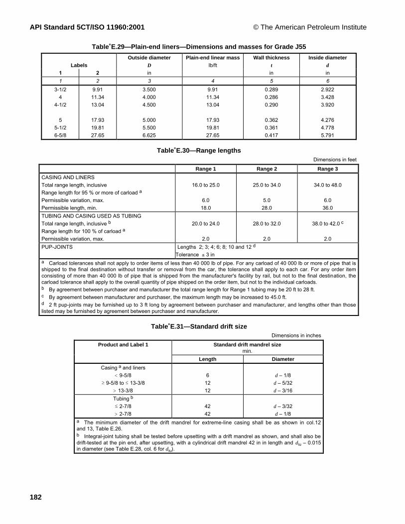
API Standard 5CT/ISO 11960:2001 © The American Petroleum Institute
182
Table E.29—Plain-end liners—Dimensions and masses for Grade J55
LabelsOutside diameter
D
Plain-end linear masslb/ft
Wall thicknesst
Inside diameterd
1 2 in in in
1 2 3 4 5 6
3-1/2
4
4-1/2
5
5-1/2
6-5/8
9.91
11.34
13.04
17.93
19.81
27.65
3.500
4.000
4.500
5.000
5.500
6.625
9.91
11.34
13.04
17.93
19.81
27.65
0.289
0.286
0.290
0.362
0.361
0.417
2.922
3.428
3.920
4.276
4.778
5.791
Table E.30—Range lengthsDimensions in feet
Range 1 Range 2 Range 3
CASING AND LINERS
Total range length, inclusive
Range length for 95Ê% or more of carload a
Permissible variation, max.
Permissible length, min.
16.0 to 25.0
6.0
18.0
25.0 to 34.0
5.0
28.0
34.0 to 48.0
6.0
36.0
TUBING AND CASING USED AS TUBING
Total range length, inclusive b
Range length for 100Ê% of carload a
Permissible variation, max.
20.0 to 24.0
2.0
28.0 to 32.0
2.0
38.0 to 42.0 c
2.0
PUP-JOINTS Lengths 2; 3; 4; 6; 8; 10 and 12 d
Tolerance ± 3 ina Carload tolerances shall not apply to order items of less than 40 000 lb of pipe. For any carload of 40 000 lb or more of pipe that isshipped to the final destination without transfer or removal from the car, the tolerance shall apply to each car. For any order itemconsisting of more than 40 000 lb of pipe that is shipped from the manufacturer's facility by rail, but not to the final destination, thecarload tolerance shall apply to the overall quantity of pipe shipped on the order item, but not to the individual carloads.b By agreement between purchaser and manufacturer the total range length for Range 1 tubing may be 20 ft to 28 ft.c By agreement between manufacturer and purchaser, the maximum length may be increased to 45.0 ft.d 2 ft pup-joints may be furnished up to 3 ft long by agreement between purchaser and manufacturer, and lengths other than thoselisted may be furnished by agreement between purchaser and manufacturer.
Table E.31—Standard drift sizeDimensions in inches
Standard drift mandrel sizemin.
Product and Label 1
Length Diameter
Casing a and liners
< 9-5/8
³ 9-5/8 to ² 13-3/8
> 13-3/8
6
12
12
d Ð 1/8
d Ð 5/32
d Ð 3/16
Tubing b
² 2-7/8
> 2-7/8
42
42
d Ð 3/32
d Ð 1/8a The minimum diameter of the drift mandrel for extreme-line casing shall be as shown in col.12and 13, Table E.26.b Integral-joint tubing shall be tested before upsetting with a drift mandrel as shown, and shall also bedrift-tested at the pin end, after upsetting, with a cylindrical drift mandrel 42 in in length and diu Ð 0.015in diameter (see Table E.28, col. 6 for diu).

© The American Petroleum Institute API Standard 5CT/ISO 11960:2001
183
Table E.32—Alternative drift size
Labels Outside diameterD
Product linear mass Alternative drift mandrel sizemin.
1 2 in lb/ft in
Length Diameter
1 2 3 4 5 6
7
7
7-3/4
8-5/8
8-5/8
9-5/8
9-5/8
9-5/8
10-3/4
10-3/4
11-3/4
11-3/4
11-3/4
13-3/8
23.00
32.00
46.10
32.00
40.00
40.00
53.50
58.40
45.50
55.50
42.00
60.00
65.00
72.00
7.000
7.000
7.750
8.625
8.625
9.625
9.625
9.625
10.750
10.750
11.750
11.750
11.750
13.375
23.0
32.0
46.1
32.0
40.0
40.0
53.5
58.4
45.5
55.5
42.0
60.0
65.0
72.0
6
6
6
6
6
12
12
12
12
12
12
12
12
12
6.250
6.000
6.500
7.875
7.625
8.750
8.500
8.375
9.875
9.625
11.000
10.625
10.625
12.250
Table E.33—Maximum permissible depth of linear imperfections
Grade Depth as % of specified wall thicknessExternal Internal
H40 Ð J55 Ð K55 Ð M65 Ð N80 Ð N80QL80 Ð C95 Ð P110 to A.9 (SR16)
12.5Ê% 12.5Ê%
C90 Ð T95 Ð P110 Ð Q125 5Ê% 5Ê%
P110 to A.9 (SR16)
and A.2 (SR2)5Ê% 5Ê%

API Standard 5CT/ISO 11960:2001 © The American Petroleum Institute
184
Table E.34—Upset products—Maximum permissible depth of imperfections
Surface Depth Measurement notes1 2 3 4
A Extreme-line casing, integral joint and external upset tubing (see Figures D.8, D.7 and D.5)A.1 All surfaces of upset and upset
run-out interval, except as statedbelow
12.5Ê% t
12.5Ê% t
5Ê% t
Percentage of specified pipe body wall thickness t ; fornon-linear imperfections; for all groups of pipe.
Percentage of specified pipe body wall thickness t; for linearimperfections; for Group 1 and Group 2 (except C90 and T95) pipe.
Percent of specified pipe body wall thickness t; for linearimperfections; for Group 3, Group 4 and Grades C90 and T95 pipe.
A.2 The minimum wall thickness in the upset run-out interval, and the maximum combined effect of coincident internal and externalimperfections in all areas, shall not total less than 87.5Ê% of the specified wall thickness.
B Extreme-line casing (see Figure D.8)B.1
B.2
Box-end external surface
Pin-end internal surface
0.010 in
0.010 in
0.015 in
For Label-1: 7-5/8 and smaller sizes. From end of pipe toa plane 4-3/4 in from the end.
For Label-1: Larger than 7-5/8. From end of pipe toa plane 6-1/2 in from the end.
From end of pipe to plane of external shoulder (bored).B.3 All machined surfaces of the box shall be free of seams, laps and cracks. The pin-and-box shall be free of any imperfections whichbreak the continuity of the threads or seals.
C Integral joint tubing (see Figure D.7)C.1
C.2
Box end external surface
Pin end internal surface
0.010 in
0.015 in
From end of pipe to a plane at a distance equal to thespecified minimum dimension Leu (Figure D.7) from end of pipe.
From end of pipe to a plane at a distance equal to thespecified minimum dimension Liu (Figure D.7) from end of pipe.
For Grades C90 and T95, the maximum permissible depth forlinear imperfections shall be 5Ê% of the specified pipe body wallthickness.
C.3 Upset underfills in the upset run-out intervals shall not be considered a defect unless the remaining wall thickness (at the upsetunderfill) is less than 87.5Ê% of the specified pipe body wall thickness.
Table E.35—Round-thread casing coupling dimensions, masses and tolerances
Size a Minimum lengthin
MasslbLabel 1
Outside diameter
Outside diameter
Short Long
Diameter ofrecess
Width of bearingface
Short LongD W NL NL Q b bin in in in
1 2 3 4 5 6 7 8 94-1/2
55-1/26-5/8
77-5/88-5/89-5/8
10-3/411-3/413-3/8
1618-5/8
20
4.5005.0005.5006.6257.0007.6258.6259.62510.75011.75013.37516.00018.62520.000
5.0005.5636.0507.3907.6568.5009.62510.62511.75012.75014.37517.00020.00021.000
6-1/46-1/26-3/47-1/47-1/47-1/27-3/47-3/4
888999
77-3/4
88-3/4
99-1/4
1010-1/2
ÑÑÑÑÑ
11 1/2
4 19/325 3/325 19/326 23/327 3/327 25/328 25/329 25/3210 29/3211 29/3213 17/3216 7/3218 27/3220 7/32
5/323/161/81/43/167/321/41/41/41/47/327/327/327/32
7.9810.2711.5420.1118.4927.1135.7939.7545.8149.9156.5776.96119.0795.73
9.1612.6814.1525.0123.8734.4647.7756.11
ÑÑÑÑÑ
126.87
See also FiguresÊD.1 and D.2
Tolerance on outside diameter W, ± 1Ê% but not greater than ± 1/8 in, Groups 1, 2 and 3.
Tolerance on outside diameter W, ± 1Ê% but not greater than in, Group 4.
a The size designation for the coupling is the same as the size designation for the pipe on which the coupling is used.
b Tolerance on diameter of recess, Q, for all groups is in.
+1/2–1/16
+0.031 0

© The American Petroleum Institute API Standard 5CT/ISO 11960:2001
185
Table E.36—Buttress thread casing coupling dimensions, masses and tolerances
Size a Outside diameterin
Masslb
Label 1
Outsidediameter
Regular Special-clearance
Minimum length Diameter ofcounterbore
Width ofbearing face
RegularSpecial
clearanceD W WC NL Q B
in in in in in
1 2 3 4 5 6 7 8 9
4-1/2
5
5-1/2
6-5/8
7
7-5/8
8-5/8
9-5/8
10-3/4
11-3/4
13-3/8
16
18-5/8
20
4.500
5.000
5.500
6.625
7.000
7.625
8.625
9.625
10.750
11.750
13.375
16.000
18.625
20.000
5.000
5.563
6.050
7.390
7.656
8.500
9.625
10.625
11.750
12.750
14.375
17.000
20.000
21.000
4.875
5.375
5.875
7.000
7.375
8.125
9.125
10.125
11.250
Ñ
Ñ
Ñ
Ñ
Ñ
8 7/8
9 1/8
9-1/4
9 5/8
10
10 3/8
10 5/8
10 5/8
10 5/8
10 5/8
10 5/8
10 5/8
10 5/8
10 5/8
4.640
5.140
5.640
6.765
7.140
7.765
8.765
9.765
10.890
11.890
13.515
16.154
18.779
20.154
1/8
5/32
5/32
1/4
7/32
5/16
3/8
3/8
3/8
3/8
3/8
3/8
3/8
3/8
10.12
13.00
14.15
24.49
23.24
34.88
45.99
51.05
56.74
61.80
70.03
88.81
138.18
110.45
7.68
8.82
9.85
12.46
13.84
20.47
23.80
26.49
29.52
Ñ
Ñ
Ñ
Ñ
Ñ
See FigureÊD.3.
Tolerance on outside diameter W, ± 1Ê% but not greater than ± 1/8 in, Groups 1, 2 and 3.
Tolerance on outside diameter W, ± 1Ê% but not greater than +-1/81/6 in, Group 4.
a The size designation for the coupling is the same as the size designation for the pipe on which the coupling is used.
Table E.37—Non-upset tubing coupling dimensions, masses and tolerances
Size a
Label 1 Outsidediameter
Outsidediameter
Minimumlength
Diameter ofrecess
Width ofbearing
face
Maximum bearingface diameter,special bevel
Mass
D W NL Q b Bf lb
in in in in in in
1 2 3 4 5 6 7 8
1.050
1.315
1.660
1.900
2-3/8
2-7/8
3-1/2
4
4-1/2
1.050
1.315
1.660
1.900
2.375
2.875
3.500
4.000
4.500
1.313
1.660
2.054
2.200
2.875
3.500
4.250
4.750
5.200
3 3/16
3-1/4
3-1/2
3-3/4
4-1/4
5 1/8
5 5/8
5-3/4
6 1/8
1.113
1.378
1.723
1.963
2.438
2.938
3.563
4.063
4.563
1/16
3/32
1/8
1/16
3/16
3/16
3/16
3/16
3/16
1.181
1.488
1.857
2.050
2.625
3.188
3.875
4.375
4.850
0.51
0.84
1.29
1.23
2.82
5.15
8.17
9.58
10.77
See FigureÊD.4.
Tolerance on outside diameter W, ± 1Ê%.a The size designation for the coupling is the same as the size designation for the pipe on which the coupling is used.

API Standard 5CT/ISO 11960:2001 © The American Petroleum Institute
186
Table E.38—External-upset tubing coupling dimensions, masses and tolerances(See Figure D.5)
Size a Outside diameter
Outsidediameter
Regular &specialbevel
Specialclearance
Maximum bearing facediameter
Bf
MasslbLabel 1
Minimumlength
Diameterof
recess
Width ofbearing
face,regular Special
bevelSpecial-
clearanceRegular Special
clearanceD W WC NL Qin in in in in in in in
1 2 3 4 5 6 7 8 9 10 111.0501.3151.660
1.9002-3/82-7/8
3-1/24
4-1/2
1.0501.3151.660
1.9002.3752.875
3.5004.0004.500
1.6601.9002.200
2.5003.0633.668
4.5005.0005.563
ÑÑÑ
Ñ2.9103.460
4.180ÑÑ
3-1/43-1/23-3/4
3 7/84 7/85-1/4
5-3/46
6 1/4
1.3781.5311.875
2.1562.6563.156
3.8134.3134.813
3/323/321/8
1/85/327/32
1/41/41/4
1.4881.6842.006
2.2972.8283.381
4.1254.6255.156
ÑÑÑ
Ñ2.7523.277
3.965ÑÑ
0.841.261.49
1.853.435.30
9.0310.6313.33
ÑÑÑ
Ñ2.353.42
5.24ÑÑ
Tolerance on outside diameter W, ± 1Ê%.
Tolerance on outside diameter WC ± 0.015 in.a The size designation for the coupling is the same as the size designation for the pipe on which the coupling is used.
Table E.39—Permissible depth of coupling external imperfectionsDimensions in inches
Coupling for pipe size Group 1Group 2 (except C90 and T95)
Group 3
Group 2 (C90 and T95)Group 4
Pits and round-bottomgouges
Grip marksand sharp-bottom gouges
Pits, round-bottom gouges,sharp-bottom gouges, grip
marks1 2 3 4 5
< 3-1/2 0.030 0.025 0.030³ 3-1/2 to ² 4-1/2 0.045 0.030 0.035
Tubing
< 6-5/8 0.035 0.030 0.030Casing a ³ 6-5/8 to ² 7-5/8 0.045 0.040 0.035
> 7-5/8 0.060 0.040 0.035a Includes casing used as tubing.
Table E.40—Frequency of tensile tests—Casing and tubing
Number of testsGroup Label 1
Maximum number ofpieces in a lot per lot per heat
1 2 3 4 5< 6-5/8 400 1 11³ 6-5/8 200 1 1² 4-1/2 Ð Grades M65, L80, C95 200 2 1² 4-1/2 Ð Grades C90, T95 200 1 Ñ> 4-1/2 Ð Grades M65, L80, C95 100 2 1
2
> 4-1/2 Ð Grades C90, T95 100 1 Ñ< 6 5/8 200 1 13³ 6 5/8 100 1 1
4 All sizes Ñ 3 ÑNOTE Table includes casing used as tubing.For Groups 1, 2 and 3 multiple-length seamless pipe, a length shall be considered as all of the sections cut from a particular multiplelength provided the pipe receives no additional heat-treatment after being cut into individual lengths.

© The American Petroleum Institute API Standard 5CT/ISO 11960:2001
187
Table E.41—Frequency of tensile tests—Couplings
Source of coupling Number of testsGroup
Material Heat treatment
Maximum number ofpieces in a lot per lot per heat
1 2 3 4 5 6Seamless pipe Coupling stock for pipe
Label 1(² 4-1/2)200 1 1
Coupling stock for pipeLabel 1 (> 4-1/2)
100 1 1
Coupling blankHeat-treat lot or 400
couplings, whichever is less1 1
Groups 1 & 3
Forged or centrifugallycast
ÑHeat-treat lot or 400
couplings, whichever is less1 1
Coupling stock for pipeLabel 1 (² 4-1/2) a
200 2 2
Coupling stock for pipeLabel 1 (> 4-1/2) a
100 2 2
Seamless pipe
Coupling blank Heat-treat lot or 400couplings, whichever is less
2 2
Group 2Grades L80 and C95
Forged or centrifugallycast
ÑHeat-treat lot or 400
couplings, whichever is less2 2
Material heat-treated in tube length 1 tube 1 per tube aGroup 2Grades C90 and T95,
Group 4 Material heat-treated as individual coupling blanksHeat-treat lot in accordance
with 10.21 Ñ
a 50Ê% each end.
Table E.42—Frequency of tensile tests—Pup-joints and accessories
Source of pup-joints and accessories Number of testsGroup
Material Heat treatment
Maximum number ofpieces in a lot per lot per heat
1 2 3 4 5 6Heat-treated separatelyfrom casing and tubing
Ñ 1 1
Casing a or tubing Batch heat treatment 100 pup-joints or 400accessories
1 1
Continuous heat treatment In accordance with 10.2 1 1² Label 1: 4-1/2:200 tubes or bars
1 1
Groups 1 & 3
Thick wall tube or barstock
Ñ> Label 1: 4-1/2:100 tubes or bars
1 1
Heat-treated separatelyfrom casing and tubing
Ñ 2 2
Casing a or tubing Batch heat treatment100 pup-joints or 400
accessories2 2
Continuous heat treatment In accordance with 10.2 2 2² Label 1: 4-1/2:200 tubes or bars
2 2
Group 2Grades L80 & C95
Thick wall tube or barstock
Ñ> Label 1: 4-1/2:100 tubes or bars
2 2
Material heat-treated in tube length 1 tube 1 per tube bGroup 2Grades C90 and T95,
Group 4 Material heat-treated in individual lengthHeat-treat lot in accordance
with 10.21 Ñ
a Includes casing used as tubing.b 50Ê% each end.

API Standard 5CT/ISO 11960:2001 © The American Petroleum Institute
188
Table E.43—Frequency of flattening tests
Casing and tubing
Group Type of heat treatment Number of tests
1 2 3 4
1, 2 and 3 Non-full body As described in Notes 1 to 5
Full body ² Label 1: 4-1/2 Same as non-full body heat-treated or1 per lot of100 lengths or less
> Label 1: 4-1/2 a Same as non-full body heat-treated or1 per lot of20 lengths or less
4 All 1 on each end of each length of pipe [see A.5 (SR11)]
Pup-joints
Group Source of pup-joint Maximum number ofpieces in a lot
Number of tests
per lot per heat
1 2 3 4 5 6
1, 2 and 3 Treated separately Batch heat-treated 100 pup-joints
Continuously heat-treated Ñ
Manufactured from EW pipe ² Label 1: 4-1/2 200 lengths
> Label 1: 4-1/2 a 100 lengths
1 1
4 All 1 on each end of eachlength of pipe
NOTE 1 The leading end of the first pipe of each coil shall have two test specimens flattened: one in the 90¡ position and one in the 0 ¡position.
NOTE 2 Two test specimens shall be flattened from an intermediate pipe of each coil: one in the 90¡ position and one in the 0¡ position.
NOTE 3 The trailing end of the last pipe of each coil shall have two test specimens flattened: one in the 90¡ position and one in the 0¡position.
NOTE 4 When a weld stop condition occurs during production of a multiple length, flattening tests with the weld at the 90¡ position and 0¡position shall be made from the crop end resulting from each side of the weld stop, and may be substituted for the intermediate flatteningtests.
NOTE 5 90¡ position: the weld is positioned at 3 oÕclock or at 9 oÕclock. 0¡ position: the weld is positioned at 6 oÕclock or at 12 oÕclock.
a Includes casing used as tubing.

© The American Petroleum Institute API Standard 5CT/ISO 11960:2001
189
Table E.44—Hydrostatic test pressure for Grade H40 casing
Test pressurepsiLabels
Round thread a
1 2
Plain end
STC LC
1 2 3 4 5
4-1/2 9.50 2 900 2 900 Ñ
5-1/2 14.00 2 800 2 800 Ñ
6-5/8 20.00 2 800 2 800 Ñ
7 17.00 2 100 2 100 Ñ
7 20.00 2 500 2 500 Ñ
7-5/8 24.00 2 500 2 500 Ñ
8-5/8 28.00 2 300 2 300 Ñ
8-5/8 32.00 2 600 2 600 Ñ
9-5/8 32.30 2 100 2 100 Ñ
9-5/8 36.00 2 300 2 300 Ñ
10-3/4 32.75 1 200
(1 700)
1 200
(1 700)
Ñ
Ñ
10-3/4 40.50 1 600
(2 100)
1 600
(2 100)
Ñ
Ñ
11-3/4 42.00 1 400
(1 800)
1 400
(1 800)
Ñ
Ñ
13-3/8 48.00 1 200
(1 600)
1 200
(1 600)
Ñ
Ñ
16 65.00 1 100
(1 500)
1 100
(1 500)
Ñ
Ñ
18-5/8 87.50 1 100
(1 500)
1 100
(1 500)
Ñ
Ñ
20 94.00 1 100
(1 400)
1 100
(1 400)
1 100
(1 400)
NOTE Alternative test pressures are given in parentheses.a The test pressures shown are for threaded and coupled pipe furnished with H40, J55 or K55 couplings.
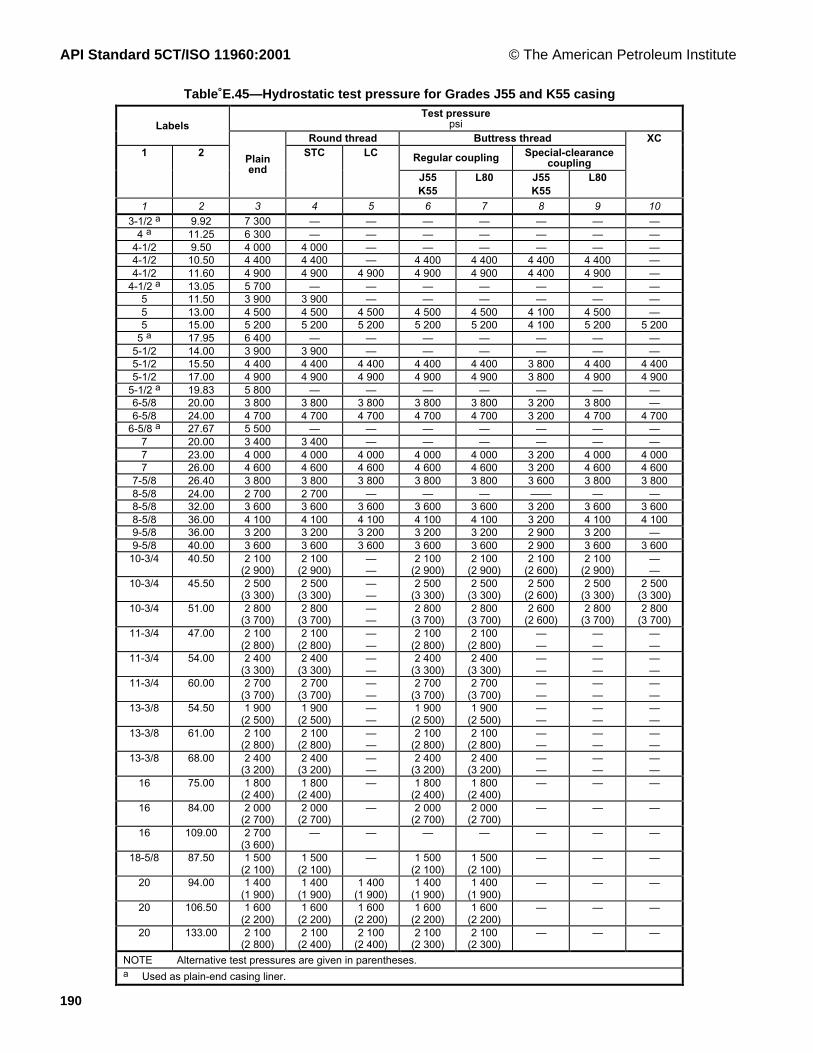
API Standard 5CT/ISO 11960:2001 © The American Petroleum Institute
190
Table E.45—Hydrostatic test pressure for Grades J55 and K55 casingTest pressure
psiLabelsRound thread Buttress thread
Regular coupling Special-clearancecoupling
1 2Plainend
STC LC
J55K55
L80 J55K55
L80
XC
1 2 3 4 5 6 7 8 9 103-1/2 a 9.92 7 300 Ñ Ñ Ñ Ñ Ñ Ñ Ñ
4 a 11.25 6 300 Ñ Ñ Ñ Ñ Ñ Ñ Ñ4-1/2 9.50 4 000 4 000 Ñ Ñ Ñ Ñ Ñ Ñ4-1/2 10.50 4 400 4 400 Ñ 4 400 4 400 4 400 4 400 Ñ4-1/2 11.60 4 900 4 900 4 900 4 900 4 900 4 400 4 900 Ñ
4-1/2 a 13.05 5 700 Ñ Ñ Ñ Ñ Ñ Ñ Ñ5 11.50 3 900 3 900 Ñ Ñ Ñ Ñ Ñ Ñ5 13.00 4 500 4 500 4 500 4 500 4 500 4 100 4 500 Ñ5 15.00 5 200 5 200 5 200 5 200 5 200 4 100 5 200 5 200
5 a 17.95 6 400 Ñ Ñ Ñ Ñ Ñ Ñ Ñ5-1/2 14.00 3 900 3 900 Ñ Ñ Ñ Ñ Ñ Ñ5-1/2 15.50 4 400 4 400 4 400 4 400 4 400 3 800 4 400 4 4005-1/2 17.00 4 900 4 900 4 900 4 900 4 900 3 800 4 900 4 900
5-1/2 a 19.83 5 800 Ñ Ñ Ñ Ñ Ñ Ñ Ñ6-5/8 20.00 3 800 3 800 3 800 3 800 3 800 3 200 3 800 Ñ6-5/8 24.00 4 700 4 700 4 700 4 700 4 700 3 200 4 700 4 700
6-5/8 a 27.67 5 500 Ñ Ñ Ñ Ñ Ñ Ñ Ñ7 20.00 3 400 3 400 Ñ Ñ Ñ Ñ Ñ Ñ7 23.00 4 000 4 000 4 000 4 000 4 000 3 200 4 000 4 0007 26.00 4 600 4 600 4 600 4 600 4 600 3 200 4 600 4 600
7-5/8 26.40 3 800 3 800 3 800 3 800 3 800 3 600 3 800 3 8008-5/8 24.00 2 700 2 700 Ñ Ñ Ñ ÑÑ Ñ Ñ8-5/8 32.00 3 600 3 600 3 600 3 600 3 600 3 200 3 600 3 6008-5/8 36.00 4 100 4 100 4 100 4 100 4 100 3 200 4 100 4 1009-5/8 36.00 3 200 3 200 3 200 3 200 3 200 2 900 3 200 Ñ9-5/8 40.00 3 600 3 600 3 600 3 600 3 600 2 900 3 600 3 600
10-3/4 40.50 2 100(2 900)
2 100(2 900)
ÑÑ
2 100(2 900)
2 100(2 900)
2 100(2 600)
2 100(2 900)
ÑÑ
10-3/4 45.50 2 500(3 300)
2 500(3 300)
ÑÑ
2 500(3 300)
2 500(3 300)
2 500(2 600)
2 500(3 300)
2 500(3 300)
10-3/4 51.00 2 800(3 700)
2 800(3 700)
ÑÑ
2 800(3 700)
2 800(3 700)
2 600(2 600)
2 800(3 700)
2 800(3 700)
11-3/4 47.00 2 100(2 800)
2 100(2 800)
ÑÑ
2 100(2 800)
2 100(2 800)
ÑÑ
ÑÑ
ÑÑ
11-3/4 54.00 2 400(3 300)
2 400(3 300)
ÑÑ
2 400(3 300)
2 400(3 300)
ÑÑ
ÑÑ
ÑÑ
11-3/4 60.00 2 700(3 700)
2 700(3 700)
ÑÑ
2 700(3 700)
2 700(3 700)
ÑÑ
ÑÑ
ÑÑ
13-3/8 54.50 1 900(2 500)
1 900(2 500)
ÑÑ
1 900(2 500)
1 900(2 500)
ÑÑ
ÑÑ
ÑÑ
13-3/8 61.00 2 100(2 800)
2 100(2 800)
ÑÑ
2 100(2 800)
2 100(2 800)
ÑÑ
ÑÑ
ÑÑ
13-3/8 68.00 2 400(3 200)
2 400(3 200)
ÑÑ
2 400(3 200)
2 400(3 200)
ÑÑ
ÑÑ
ÑÑ
16 75.00 1 800(2 400)
1 800(2 400)
Ñ 1 800(2 400)
1 800(2 400)
Ñ Ñ Ñ
16 84.00 2 000(2 700)
2 000(2 700)
Ñ 2 000(2 700)
2 000(2 700)
Ñ Ñ Ñ
16 109.00 2 700(3 600)
Ñ Ñ Ñ Ñ Ñ Ñ Ñ
18-5/8 87.50 1 500(2 100)
1 500(2 100)
Ñ 1 500(2 100)
1 500(2 100)
Ñ Ñ Ñ
20 94.00 1 400(1 900)
1 400(1 900)
1 400(1 900)
1 400(1 900)
1 400(1 900)
Ñ Ñ Ñ
20 106.50 1 600(2 200)
1 600(2 200)
1 600(2 200)
1 600(2 200)
1 600(2 200)
Ñ Ñ Ñ
20 133.00 2 100(2 800)
2 100(2 400)
2 100(2 400)
2 100(2 300)
2 100(2 300)
Ñ Ñ Ñ
NOTE Alternative test pressures are given in parentheses.a Used as plain-end casing liner.

© The American Petroleum Institute API Standard 5CT/ISO 11960:2001
191
Table E.46—Hydrostatic test pressure for Grade M65 casing
Test pressurepsi
Labels
Round thread a Buttress thread a
1 2
Plain end
STC LCRegularcoupling
Special-clearancecoupling
1 2 3 4 5 6 7
4-1/2 9.50 4 700 4 700 Ñ Ñ Ñ4-1/2 10.50 5 200 5 200 Ñ 5 200 5 2004-1/2 11.60 5 800 5 800 5 800 5 800 5 8004-1/2 13.50 6 700 Ñ 6 700 6 700 6 400
5 11.50 4 600 4 600 Ñ Ñ Ñ5 13.00 5 300 5 300 5 300 5 300 5 3005 15.00 6 200 Ñ 6 200 6 200 6 0005 18.00 7 500 Ñ 7 500 7 500 6 0005 21.40 9 100 Ñ 8 700 7 900 6 000
5-1/2 14.00 4 600 4 600 Ñ Ñ Ñ5-1/2 15.50 5 200 5 200 5 200 5 200 5 2005-1/2 17.00 5 700 Ñ 5 700 5 700 5 5005-1/2 20.00 6 800 Ñ 6 800 6 800 5 5005-1/2 23.00 7 800 Ñ 7 800 7 200 5 5006-5/8 20.00 4 500 4 500 4 500 4 500 4 5006-5/8 24.00 5 500 Ñ 5 500 5 500 4 7006-5/8 28.00 6 500 Ñ 6 500 6 500 4 700
7 20.00 4 000 4 000 Ñ Ñ Ñ7 23.00 4 700 Ñ 4 700 4 700 4 6007 26.00 5 400 Ñ 5 400 5 400 4 6007 29.00 6 100 Ñ 6 100 6 100 4 6007 32.00 6 700 Ñ 6 700 6 700 4 600
7-5/8 26.40 4 500 4 500 4 500 4 500 4 5007-5/8 29.70 5 100 Ñ 5 100 5 100 5 1007-5/8 33.70 5 900 Ñ 5 900 5 900 5 2008-5/8 24.00 3 200 3 200 Ñ Ñ Ñ8-5/8 28.00 3 700 3 700 Ñ Ñ Ñ8-5/8 32.00 4 200 4 200 4 200 4 200 4 2008-5/8 36.00 4 800 4 800 4 800 4 800 4 7008-5/8 40.00 5 400 Ñ 5 400 5 400 4 7009-5/8 36.00 3 800 3 800 3 800 3 800 3 8009-5/8 40.00 4 300 4 300 4 300 4 300 4 3009-5/8 43.50 4 700 Ñ 4 700 4 700 4 3009-5/8 47.00 5 100 Ñ 5 100 5 100 4 300
10-3/4 40.50 3 400 3 400 Ñ 3 400 3 40010-3/4 45.50 3 900 3 900 Ñ 3 900 3 80010-3/4 51.00 4 400 4 400 Ñ 4 400 3 80010-3/4 55.50 4 800 4 800 Ñ 4 800 3 80011-3/4 47.00 3 300 3 300 Ñ 3 300 Ñ11-3/4 54.00 3 900 3 900 Ñ 3 900 Ñ11-3/4 60.00 4 300 4 300 Ñ 4 300 Ñ13-3/8 54.50 3 000 3 000 Ñ 3 000 Ñ13-3/8 61.00 3 300 3 300 Ñ 3 300 Ñ13-3/8 68.00 3 700 3 700 Ñ 3 700 Ñ
16 75.00 2 800 2 800 Ñ 2 800 Ñ16 84.00 3 200 3 200 Ñ 3 200 Ñ
18-5/8 87.50 2 400 2 400 Ñ 2 400 Ñ20 94.00 2 300 2 100 2 100 2 300 Ñ20 106.50 2 600 2 100 2 100 2 300 Ñ
a Threaded and coupled Grade M65 casing shall be furnished with Grade L80 couplings.

API Standard 5CT/ISO 11960:2001 © The American Petroleum Institute
192
Table E.47—Hydrostatic test pressure for Grade L80 casing
Test pressurepsiLabels
Round thread Buttress thread
1 2 Plain end STC LC Regularcoupling
Special-clearancecoupling
XC
1 2 3 4 5 6 7 8
4-1/2 11.60 7 100 Ñ 7 100 7 100 6 400 Ñ
4-1/2 13.50 8 200 Ñ 8 200 7 800 6 400 Ñ
5 15.00 7 600 Ñ 7 600 7 600 6 000 7 600
5 18.00 9 300 Ñ 8 700 7 900 6 000 9 300
5 21.40 10 000 Ñ 8 700 7 900 6 000 Ñ
5 23.20 10 000 Ñ 8 700 7 900 6 000 Ñ
5 24.10 10 000 Ñ 8 700 7 900 6 000 Ñ
5-1/2 17.00 7 100 Ñ 7 100 7 100 5 500 7 100
5-1/2 20.00 8 400 Ñ 7 900 7 200 5 500 8 400
5-1/2 23.00 9 700 Ñ 7 900 7 200 5 500 9 700
6-5/8 24.00 6 800 Ñ 6 800 6 800 4 700 6 800
6-5/8 28.00 8 100 Ñ 8 100 7 900 4 700 8 100
6-5/8 32.00 9 200 Ñ 8 500 7 900 4 700 9 200
7 23.00 5 800 Ñ 5 800 5 800 4 600 5 800
7 26.00 6 600 Ñ 6 600 6 600 4 600 6 600
7 29.00 7 500 Ñ 7 400 6 800 4 600 7 500
7 32.00 8 300 Ñ 7 400 6 800 4 600 8 300
7 35.00 9 100 Ñ 7 400 6 800 4 600 9 100
7 38.00 9 900 Ñ 7 400 6 800 4 600 9 900
7-5/8 26.40 5 500 Ñ 5 500 5 500 5 200 5 500
7-5/8 29.70 6 300 Ñ 6 300 6 300 5 200 6 300
7-5/8 33.70 7 200 Ñ 7 200 7 200 5 200 7 200
7-5/8 39.00 8 400 Ñ 8 400 7 800 5 200 8 400
7-5/8 42.80 9 400 Ñ 8 400 7 800 5 200 Ñ
7-5/8 45.30 10 000 Ñ 8 400 7 800 5 200 Ñ
7-5/8 47.10 10 000 Ñ 8 400 7 800 5 200 Ñ
7-3/4 46.10 9 800 Ñ --- Ñ Ñ Ñ
8-5/8 36.00 5 900 Ñ 5 900 5 900 4 700 5 900
8-5/8 40.00 6 700 Ñ 6 700 6 700 4 700 6 700
8-5/8 44.00 7 400 Ñ 7 400 7 400 4 700 7 400
8-5/8 49.00 8 300 Ñ 8 300 7 800 4 700 8 300
9-5/8 40.00 5 300 Ñ 5 300 5 300 4 300 5 300
9-5/8 43.50 5 800 Ñ 5 800 5 800 4 300 5 800
9-5/8 47.00 6 300 Ñ 6 300 6 300 4 300 6 300
9-5/8 53.50 7 200 Ñ 7 200 7 100 4 300 7 200
9-5/8 58.40 7 900 Ñ 7 700 7 100 4 300 Ñ
10-3/4 51.00 5 400 5 400 Ñ 5 400 3 800 5 400
10-3/4 55.50 5 900 5 900 Ñ 5 900 3 800 5 900
11-3/4 60.00 5 300 5 300 Ñ 5 300 Ñ Ñ
11-3/4 65.00 5 800 Ñ Ñ Ñ Ñ Ñ
11-3/4 71.00 6 300 Ñ Ñ Ñ Ñ Ñ
13-3/8 68.00 4 600 4 600 Ñ 4 600 Ñ Ñ
13-3/8 72.00 4 900 4 600 Ñ 4 900 Ñ Ñ
16 109.00 5 200 Ñ Ñ Ñ Ñ Ñ
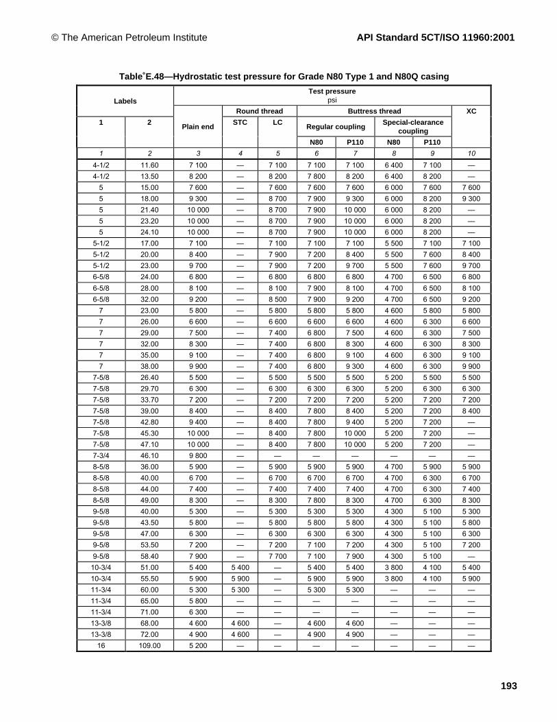
© The American Petroleum Institute API Standard 5CT/ISO 11960:2001
193
Table E.48—Hydrostatic test pressure for Grade N80 Type 1 and N80Q casing
Test pressurepsiLabels
Round thread Buttress thread
Regular couplingSpecial-clearance
coupling1 2
Plain endSTC LC
N80 P110 N80 P110
XC
1 2 3 4 5 6 7 8 9 10
4-1/2 11.60 7 100 Ñ 7 100 7 100 7 100 6 400 7 100 Ñ
4-1/2 13.50 8 200 Ñ 8 200 7 800 8 200 6 400 8 200 Ñ
5 15.00 7 600 Ñ 7 600 7 600 7 600 6 000 7 600 7 600
5 18.00 9 300 Ñ 8 700 7 900 9 300 6 000 8 200 9 300
5 21.40 10 000 Ñ 8 700 7 900 10 000 6 000 8 200 Ñ
5 23.20 10 000 Ñ 8 700 7 900 10 000 6 000 8 200 Ñ
5 24.10 10 000 Ñ 8 700 7 900 10 000 6 000 8 200 Ñ
5-1/2 17.00 7 100 Ñ 7 100 7 100 7 100 5 500 7 100 7 100
5-1/2 20.00 8 400 Ñ 7 900 7 200 8 400 5 500 7 600 8 400
5-1/2 23.00 9 700 Ñ 7 900 7 200 9 700 5 500 7 600 9 700
6-5/8 24.00 6 800 Ñ 6 800 6 800 6 800 4 700 6 500 6 800
6-5/8 28.00 8 100 Ñ 8 100 7 900 8 100 4 700 6 500 8 100
6-5/8 32.00 9 200 Ñ 8 500 7 900 9 200 4 700 6 500 9 200
7 23.00 5 800 Ñ 5 800 5 800 5 800 4 600 5 800 5 800
7 26.00 6 600 Ñ 6 600 6 600 6 600 4 600 6 300 6 600
7 29.00 7 500 Ñ 7 400 6 800 7 500 4 600 6 300 7 500
7 32.00 8 300 Ñ 7 400 6 800 8 300 4 600 6 300 8 300
7 35.00 9 100 Ñ 7 400 6 800 9 100 4 600 6 300 9 100
7 38.00 9 900 Ñ 7 400 6 800 9 300 4 600 6 300 9 900
7-5/8 26.40 5 500 Ñ 5 500 5 500 5 500 5 200 5 500 5 500
7-5/8 29.70 6 300 Ñ 6 300 6 300 6 300 5 200 6 300 6 300
7-5/8 33.70 7 200 Ñ 7 200 7 200 7 200 5 200 7 200 7 200
7-5/8 39.00 8 400 Ñ 8 400 7 800 8 400 5 200 7 200 8 400
7-5/8 42.80 9 400 Ñ 8 400 7 800 9 400 5 200 7 200 Ñ
7-5/8 45.30 10 000 Ñ 8 400 7 800 10 000 5 200 7 200 Ñ
7-5/8 47.10 10 000 Ñ 8 400 7 800 10 000 5 200 7 200 Ñ
7-3/4 46.10 9 800 Ñ Ñ Ñ Ñ Ñ Ñ Ñ
8-5/8 36.00 5 900 Ñ 5 900 5 900 5 900 4 700 5 900 5 900
8-5/8 40.00 6 700 Ñ 6 700 6 700 6 700 4 700 6 300 6 700
8-5/8 44.00 7 400 Ñ 7 400 7 400 7 400 4 700 6 300 7 400
8-5/8 49.00 8 300 Ñ 8 300 7 800 8 300 4 700 6 300 8 300
9-5/8 40.00 5 300 Ñ 5 300 5 300 5 300 4 300 5 100 5 300
9-5/8 43.50 5 800 Ñ 5 800 5 800 5 800 4 300 5 100 5 800
9-5/8 47.00 6 300 Ñ 6 300 6 300 6 300 4 300 5 100 6 300
9-5/8 53.50 7 200 Ñ 7 200 7 100 7 200 4 300 5 100 7 200
9-5/8 58.40 7 900 Ñ 7 700 7 100 7 900 4 300 5 100 Ñ
10-3/4 51.00 5 400 5 400 Ñ 5 400 5 400 3 800 4 100 5 400
10-3/4 55.50 5 900 5 900 Ñ 5 900 5 900 3 800 4 100 5 900
11-3/4 60.00 5 300 5 300 Ñ 5 300 5 300 Ñ Ñ Ñ
11-3/4 65.00 5 800 Ñ Ñ Ñ Ñ Ñ Ñ Ñ
11-3/4 71.00 6 300 Ñ Ñ Ñ Ñ Ñ Ñ Ñ
13-3/8 68.00 4 600 4 600 Ñ 4 600 4 600 Ñ Ñ Ñ
13-3/8 72.00 4 900 4 600 Ñ 4 900 4 900 Ñ Ñ Ñ
16 109.00 5 200 Ñ Ñ Ñ Ñ Ñ Ñ Ñ

API Standard 5CT/ISO 11960:2001 © The American Petroleum Institute
194
Table E.49—Hydrostatic test pressure for Grade C90 casing
Test pressurepsiLabels
Round thread Buttress thread
1 2 Plain end STC LC Regularcoupling
Special-clearancecoupling
XC
1 2 3 4 5 6 7 8
4-1/2 11.60 8 000 Ñ 8 000 8 000 7 200 Ñ
4-1/2 13.50 9 300 Ñ 9 300 8 800 7 200 Ñ
5 15.00 8 500 Ñ 8 500 8 500 6 700 8 500
5 18.00 10 000 Ñ 9 700 8900 6 700 10 000
5 21.40 10 000 Ñ 9 700 8 900 6 700 Ñ
5 23.20 10 000 Ñ 9 700 8 900 6 700 Ñ
5 24.10 10 000 Ñ 9 700 8 900 6 700 Ñ
5-1/2 17.00 8 000 Ñ 8 000 8 000 6 200 8 000
5-1/2 20.00 9 500 Ñ 8 900 8 100 6 200 9 500
5-1/2 23.00 10 000 Ñ 8 900 8 100 6 200 10 000
5-1/2 26.80 10 000 Ñ Ñ Ñ Ñ Ñ
5-1/2 29.70 10 000 Ñ Ñ Ñ Ñ Ñ
5-1/2 32.60 10 000 Ñ Ñ Ñ Ñ Ñ
5-1/2 35.30 10 000 Ñ Ñ Ñ Ñ Ñ
5-1/2 38.00 10 000 Ñ Ñ Ñ Ñ Ñ
5-1/2 40.50 10 000 Ñ Ñ Ñ Ñ Ñ
5-1/2 43.10 10 000 Ñ Ñ Ñ Ñ Ñ
6-5/8 24.00 7700 Ñ 7 700 7 700 5 300 7 700
6-5/8 28.00 9100 Ñ 9 100 8 800 5 300 9 100
6-5/8 32.00 10 000 Ñ 9 600 8 800 5 300 10 000
7 23.00 6 500 Ñ 6 500 6 500 5 200 6 500
7 26.00 7 400 Ñ 7 400 7 400 5 200 7 400
7 29.00 8 400 Ñ 8 300 7 600 5 200 8 400
7 32.00 9 300 Ñ 8 300 7 600 5 200 9 300
7 35.00 10 000 Ñ 8 300 7 600 5 200 10 000
7 38.00 10 000 Ñ 8 300 7600 5 200 10 000
7 42.70 10 000 Ñ Ñ Ñ Ñ Ñ
7 46.40 10 000 Ñ Ñ Ñ Ñ Ñ
7 50.10 10 000 Ñ Ñ Ñ Ñ Ñ
7 53.60 10 000 Ñ Ñ Ñ Ñ Ñ
7 57.10 10 000 Ñ Ñ Ñ Ñ Ñ
7-5/8 26.40 6 200 Ñ 6 200 6 200 5 900 6 200
7-5/8 29.70 7 100 Ñ 7 100 7 100 5 900 7 100
7-5/8 33.70 8 100 Ñ 8 100 8 100 5 900 8 100
7-5/8 39.00 9 400 Ñ 9 400 8 800 5 900 9 400
7-5/8 42.80 10 000 Ñ 9 400 8 800 5 900 Ñ
7-5/8 45.30 10 000 Ñ 9 400 8 800 5 900 Ñ
7-5/8 47.10 10 000 Ñ 9 400 8 800 5 900 Ñ
7-5/8 51.20 10 000 Ñ Ñ Ñ Ñ Ñ
7-5/8 55.30 10 000 Ñ Ñ Ñ Ñ Ñ
7-3/4 46.10 10 000 Ñ Ñ Ñ Ñ Ñ
8-5/8 36.00 6 700 Ñ 6 700 6 700 5 300 6 700
8-5/8 40.00 7 500 Ñ 7 500 7 500 5 300 7 500
8-5/8 44.00 8 300 Ñ 8 300 8 300 5 300 8 300
8-5/8 49.00 9 300 Ñ 9 300 8 800 5 300 9 300

© The American Petroleum Institute API Standard 5CT/ISO 11960:2001
195
Table E.49 (continued )
Test pressurepsiLabels
Round thread Buttress thread
1 2 Plain end STC LC Regularcoupling
Special-clearancecoupling
XC
1 2 3 4 5 6 7 8
9-5/8 40.00 5 900 Ñ 5 900 5 900 4 800 5 900
9-5/8 43.50 6 500 Ñ 6 500 6 500 4 800 6 500
9-5/8 47.00 7 100 Ñ 7 100 7 100 4 800 7 100
9-5/8 53.50 8 200 Ñ 8 200 7 900 4 800 8 200
9-5/8 58.40 8 900 Ñ 8 500 7 900 4 800 Ñ
9-5/8 59.40 9 100 Ñ Ñ Ñ Ñ Ñ
9-5/8 64.90 10 000 Ñ Ñ Ñ Ñ Ñ
9-5/8 70.30 10 000 Ñ Ñ Ñ Ñ Ñ
9-5/8 75.60 10 000 Ñ Ñ Ñ Ñ Ñ
10-3/4 51.00 6 000 6 000 Ñ 6 000 4 100 6 000
10-3/4 55.50 6 600 6 600 Ñ 6 600 4 100 6 600
10-3/4 60.70 7 300 6 900 Ñ 7 200 4 100 7 300
10-3/4 65.70 8 000 6 900 Ñ 7 200 4 100 Ñ
10-3/4 73.20 9 000 Ñ Ñ Ñ Ñ Ñ
10-3/4 79.20 9 800 Ñ Ñ Ñ Ñ Ñ
10-3/4 85.30 10 000 Ñ Ñ Ñ Ñ Ñ
11-3/4 60.00 6 000 5 800 Ñ 6 000 Ñ Ñ
11-3/4 65.00 6 500 Ñ Ñ Ñ Ñ Ñ
11-3/4 71.00 7 100 Ñ Ñ Ñ Ñ Ñ
13-3/8 68.00 5 200 4 600 Ñ 4 900 Ñ Ñ
13-3/8 72.00 5 500 4 600 Ñ 4 900 Ñ Ñ

API Standard 5CT/ISO 11960:2001 © The American Petroleum Institute
196
Table E.50—Hydrostatic test pressure for Grade C95 casing
Test pressurepsiLabels
Round thread Buttress thread
1 2 Plain end STC LC Regularcoupling
Special-clearancecoupling
XC
1 2 3 4 5 6 7 8
4-1/2 11.60 8 400 Ñ 8 400 8 400 7 600 Ñ
4-1/2 13.50 9 800 Ñ 9 800 9 300 7 600 Ñ
5 15.00 9 000 Ñ 9 000 9 000 7 100 9 000
5 18.00 10 000 Ñ 10 000 9 400 7 100 10 000
5 21.40 10 000 Ñ 10 000 9 400 7 100 Ñ
5 23.20 10 000 Ñ 10 000 9 400 7 100 Ñ
5 24.10 10 000 Ñ 10 000 9 400 7 100 Ñ
5-1/2 17.00 8 400 Ñ 8 400 8 400 6 500 8 400
5-1/2 20.00 10 000 Ñ 9 400 8 500 6 500 10 000
5-1/2 23.00 10 000 Ñ 9 400 8 500 6 500 10 000
6-5/8 24.00 8 100 Ñ 8 100 8 100 5 600 8 100
6-5/8 28.00 9 600 Ñ 9 600 9 300 5 600 9 600
6-5/8 32.00 10 000 Ñ 10 000 9 300 5 600 10 000
7 23.00 6 900 Ñ 6 900 6 900 5 500 6 900
7 26.00 7 900 Ñ 7 900 7 900 5 500 7 900
7 29.00 8 900 Ñ 8 800 8 000 5 500 8 900
7 32.00 9 800 Ñ 8 800 8 000 5 500 9 800
7 35.00 10 000 Ñ 8 800 8 000 5 500 10 000
7 38.00 10 000 Ñ 8 800 8 000 5 500 10 000
7-5/8 26.40 6 500 Ñ 6 500 6 500 6 200 6 500
7-5/8 29.70 7 500 Ñ 7 500 7 500 6 200 7 500
7-5/8 33.70 8 600 Ñ 8 600 8 600 6 200 8 600
7-5/8 39.00 10 000 Ñ 10 000 9 300 6 200 10 000
7-5/8 42.80 10 000 Ñ 10 000 9 300 6 200 Ñ
7-5/8 45.30 10 000 Ñ 10 000 9 300 6 200 Ñ
7-5/8 47.10 10 000 Ñ 10 000 9 300 6 200 Ñ
7-3/4 46.10 10 000 Ñ Ñ Ñ Ñ Ñ
8-5/8 36.00 7 000 Ñ 7 000 7 000 5 600 7 000
8-5/8 40.00 7 900 Ñ 7 900 7 900 5 600 7 900
8-5/8 44.00 8 800 Ñ 8 800 8 800 5 600 8 800
8-5/8 49.00 9 800 Ñ 9 800 9 300 5 600 9 800
9-5/8 40.00 6 200 Ñ 6 200 6 200 5 100 6 200
9-5/8 43.50 6 900 Ñ 6 900 6 900 5 100 6 900
9-5/8 47.00 7 500 Ñ 7 500 7 500 5 100 7 500
9-5/8 53.50 8 600 Ñ 8 500 8 400 5 100 8 600
9-5/8 58.40 9 400 Ñ 8 500 8 400 5 100 Ñ
10-3/4 51.00 6 400 6 400 Ñ 6 400 4 100 6 400
10-3/4 55.50 7 000 6 900 Ñ 7 000 4 100 7 000
11-3/4 60.00 6 300 5 800 Ñ 6 300 Ñ Ñ
11-3/4 65.00 6 900 Ñ Ñ Ñ Ñ Ñ
11-3/4 71.00 7 500 Ñ Ñ Ñ Ñ Ñ
13-3/8 68.00 5 500 4 600 Ñ 4 900 Ñ Ñ
13-3/8 72.00 5 800 4 600 Ñ 4 900 Ñ Ñ
16 109.00 6 200 Ñ Ñ Ñ Ñ Ñ

© The American Petroleum Institute API Standard 5CT/ISO 11960:2001
197
Table E.51—Hydrostatic test pressure for Grade T95 casing
Test pressurepsiLabels
Round thread Buttress thread
1 2 Plain end STC LC Regularcoupling
Special-clearancecoupling
XC
1 2 3 4 5 6 7 8
4-1/2 11.60 8 400 Ñ 8 400 8 400 7 600 Ñ4-1/2 13.50 9 800 Ñ 9 800 9 300 7 600 Ñ
5 15.00 9 000 Ñ 9 000 9 000 7 100 9 0005 18.00 10 000 Ñ 10 000 9 400 7 100 10 0005 21.40 10 000 Ñ 10 000 9 400 7 100 Ñ5 23.20 10 000 Ñ 10 000 9 400 7 100 Ñ5 24.10 10 000 Ñ 10 000 9 400 7 100 Ñ
5-1/2 17.00 8 400 Ñ 8 400 8 400 6 500 8 4005-1/2 20.00 10 000 Ñ 9 400 8 500 6 500 10 0005-1/2 23.00 10 000 Ñ 9 400 8 500 6 500 10 0005-1/2 26.80 10 000 Ñ Ñ Ñ Ñ Ñ5-1/2 29.70 10 000 Ñ Ñ Ñ Ñ Ñ5-1/2 32.60 10 000 Ñ Ñ Ñ Ñ Ñ5-1/2 35.30 10 000 Ñ Ñ Ñ Ñ Ñ5-1/2 38.00 10 000 Ñ Ñ Ñ Ñ Ñ5-1/2 40.50 10 000 Ñ Ñ Ñ Ñ Ñ5-1/2 43.10 10 000 Ñ Ñ Ñ Ñ Ñ6-5/8 24.00 8 100 Ñ 8 100 8 100 5 600 8 1006-5/8 28.00 9 600 Ñ 9 600 9 300 5 600 9 6006-5/8 32.00 10 000 Ñ 10 000 9 300 5 600 10 000
7 23.00 6 900 Ñ 6 900 6 900 5 500 6 9007 26.00 7 900 Ñ 7 900 7 900 5 500 7 9007 29.00 8 900 Ñ 8 800 8 000 5 500 8 8007 32.00 9 800 Ñ 8 800 8 000 5 500 9 8007 35.00 10 000 Ñ 8 800 8 000 5 500 10 0007 38.00 10 000 Ñ 8 800 8 000 5 500 10 0007 42.70 10 000 Ñ Ñ Ñ Ñ Ñ7 46.40 10 000 Ñ Ñ Ñ Ñ Ñ7 50.10 10 000 Ñ Ñ Ñ Ñ Ñ7 53.60 10 000 Ñ Ñ Ñ Ñ Ñ7 57.10 10 000 Ñ Ñ Ñ Ñ Ñ
7-5/8 26.40 6 500 Ñ 6 500 6 500 6 200 6 5007-5/8 29.70 7 500 Ñ 7 500 7 500 6 200 7 5007-5/8 33.70 8 600 Ñ 8 600 8 600 6 200 8 6007-5/8 39.00 10 000 Ñ 10 000 9 300 6 200 10 0007-5/8 42.80 10 000 Ñ 10 000 9 300 6 200 Ñ7-5/8 45.30 10 000 Ñ 10 000 9 300 6 200 Ñ7-5/8 47.10 10 000 Ñ 10 000 9 300 6 200 Ñ7-5/8 51.20 10 000 Ñ Ñ Ñ Ñ Ñ7-5/8 55.30 10 000 Ñ Ñ Ñ Ñ Ñ7-3/4 46.10 10 000 Ñ Ñ Ñ Ñ Ñ8-5/8 36.00 7 000 Ñ 7 000 7 000 5 600 7 0008-5/8 40.00 7 900 Ñ 7 900 7 900 5 600 7 9008-5/8 44.00 8 800 Ñ 8 800 8 800 5 600 8 8008-5/8 49.00 9 800 Ñ 9 800 9 300 5 600 9 8009-5/8 40.00 6 200 Ñ 6 200 6 200 5 100 6 2009-5/8 43.50 6 900 Ñ 6 900 6 900 5 100 6 9009-5/8 47.00 7 500 Ñ 7 500 7 500 5 100 7 5009-5/8 53.50 8 600 Ñ 8 500 8 400 5 100 8 6009-5/8 58.40 9 400 Ñ 8 500 8 400 5 100 Ñ9-5/8 59.40 9 600 Ñ Ñ Ñ Ñ Ñ9-5/8 64.90 10 000 Ñ Ñ Ñ Ñ Ñ9-5/8 70.30 10 000 Ñ Ñ Ñ Ñ Ñ9-5/8 75.60 10 000 Ñ Ñ Ñ Ñ Ñ

API Standard 5CT/ISO 11960:2001 © The American Petroleum Institute
198
Table˚E.51˚(continued)
Test pressurepsiLabels
Round thread Buttress thread
1 2 Plain end STC LC Regularcoupling
Special-clearancecoupling
XC
1 2 3 4 5 6 7 8
10-3/4 51.00 6 400 6 400 Ñ 6 400 4 100 6 400
10-3/4 55.50 7 000 6 900 Ñ 7 000 4 100 7 000
10-3/4 60.70 7 700 6 900 Ñ 7 500 4 100 7 600
10-3/4 65.70 8 400 6 900 Ñ 7 500 4 100 Ñ
10-3/4 73.20 9 500 Ñ Ñ Ñ Ñ Ñ
10-3/4 79.20 10 000 Ñ Ñ Ñ Ñ Ñ
10-3/4 85.30 10 000 Ñ Ñ Ñ Ñ Ñ
11-3/4 60.00 6 300 5 800 Ñ 6 300 Ñ Ñ
11-3/4 65.00 6 900 Ñ Ñ Ñ Ñ Ñ
11-3/4 71.00 7 500 Ñ Ñ Ñ Ñ Ñ
13-3/8 68.00 5 500 4 600 Ñ 4 900 Ñ Ñ
13-3/8 72.00 5 800 4 600 Ñ 4 900 Ñ Ñ

© The American Petroleum Institute API Standard 5CT/ISO 11960:2001
199
Table E.52—Hydrostatic test pressure for Grade P110 casing
Test pressurepsi
Round thread Buttress threadLabels
Regular couplingSpecial-clearance
coupling
1 2
Plainend
STC LC
P110 Q125 P110 Q125
XC
1 2 3 4 5 6 7 8 9 10
4-1/2 11.60 9 800 Ñ 9 800 9 800 9 800 8 800 9 800 Ñ
4-1/2 13.50 10 000(11 300)
ÑÑ
10 000(11 300)
10 000(10 800)
10 000(11 300)
8 800(8 800)
10 000(10 000)
ÑÑ
4-1/2 15.10 10 000(13 200)
ÑÑ
10 000(11 700)
10 000(10 800)
10 000(12 200)
8 800(8 800)
10 000(10 000)
ÑÑ
5 15.00 10 000(10 400)
ÑÑ
10 000(10 400)
10 000(10 400)
10 000(10 400)
8 200(8 200)
9 300(9 300)
10 000(10 400)
5 18.00 10 000(12 700)
ÑÑ
10 000(11 900)
10 000(10 900)
10 000(12 400)
8 200(8 200)
9 300(9 300)
10 000(12 700)
5 21.40 10 000(15 400)
ÑÑ
10 000(11 900)
10 000(10 900)
10 000(12 400)
8 200(8 200)
9 300(9 300)
ÑÑ
5 23.20 10 000(16 800)
ÑÑ
10 000(11 900)
10 000(10 900)
10 000(12 400)
8 200(8 200)
9 300(9 300)
ÑÑ
5 24.10 10 000(17 600)
ÑÑ
10 000(11 900)
10 000(10 900)
10 000(12 400)
8 200(8 200)
9 300(9 300)
ÑÑ
5-1/2 17.00 9 700 Ñ 9 700 9 700 9 700 7 600 8 600 9 700
5-1/2 20.00 10 000(11 600)
ÑÑ
10 000(10 900)
9 900(9 900)
10 000(11 200)
7 600(7 600)
8 600(8 600)
10 000(11 600)
5-1/2 23.00 10 000(13 300)
ÑÑ
10 000(10 900)
9 900(9 900)
10 000(11 200)
7 600(7 600)
8 600(8 600)
10 000(13 300)
6-5/8 24.00 9 400 Ñ 9 400 9 400 9 400 6 500 7 400 9 400
6-5/8 28.00 10 000(11 100)
ÑÑ
10 000(11 100)
10 000(10 800)
10 000(11 100)
6 500(6 500)
7 400(7 400)
10 000(11 100)
6-5/8 32.00 10 000(12 600)
ÑÑ
10 000(11 700)
10 000(10 800)
10 000(12 300)
6 500(6 500)
7 400(7 400)
10 00012 600
7 26.00 9 100 Ñ 9 100 9 100 9 100 6 300 7 200 9 100
7 29.00 10 000(10 300)
ÑÑ
9 500(9 500)
9 300(9 300)
10 000(10 300)
6 300(6 300)
7 200(7 200)
10 000(10 300)
7 32.00 10 000(11 400)
ÑÑ
9 500(9 500)
9 300(9 300)
10 000(10 600)
6 300(6 300)
7 200(7 200)
10 000(11 400)
7 35.00 10 000(12 500)
ÑÑ
9 500(9 500)
9 300(9 300)
10 000(10 600)
6 300(6 300)
7 200(7 200)
10 000(12 500)
7 38.00 10 000(13 600)
ÑÑ
9 500(9 500)
9 300(9 300)
10 000(10 600)
6 300(6 300)
7 200(7 200)
10 000(13 600)
7-5/8 29.70 8 700 Ñ 8 700 8 700 8 700 7 200 8 000 8 700
7-5/8 33.70 9 900 Ñ 9 900 9 900 9 900 7 200 8 000 9 900
7-5/8 39.00 10 000(11 500)
ÑÑ
10 000(11 500)
10 000(10 800)
10 000(11 500)
7 200(7 200)
8 000(8 000)
10 000(11 500)
7-5/8 42.80 10 000(13 000)
ÑÑ
10 000(11 500)
10 000(10 800)
10 000(12 200)
7 200(7 200)
8 000(8 000)
ÑÑ
7-5/8 45.30 10 000(13 700)
ÑÑ
10 000(11 500)
10 000(10 800)
10 000(12 200)
7 200(7 200)
8 000(8 000)
ÑÑ
7-5/8 47.10 10 000(14 400)
ÑÑ
10 000(11 500)
10 000(10 800)
10 000(12 200)
7 200(7 200)
8 000(8 000)
ÑÑ
7-3/4 46.10 10 000(13 500)
ÑÑ
ÑÑ
ÑÑ
ÑÑ
ÑÑ
ÑÑ
ÑÑ
8-5/8 40.00 9 200 Ñ 9 200 9 200 9 200 6 300 6 300 9 200
8-5/8 44.00 10 000(10 200)
ÑÑ
10 000(10 200)
10 000(10 200)
10 000(10 200)
6 300(6 300)
6 300(6 300)
10 000(10 200)
8-5/8 49.00 10 000(11 400)
ÑÑ
10 000(10 400)
10 000(10 700)
10 000(11 200)
6 300(6 300)
6 300(6 300)
10 000(11 400)
See note at end of table.

API Standard 5CT/ISO 11960:2001 © The American Petroleum Institute
200
Table E.52 (continued )
Test pressurepsi
Round thread Buttress threadLabels
Regular couplingSpecial-clearance
coupling
1 2
Plainend
STC LC
P110 Q125 P110 Q125
XC
1 2 3 4 5 6 7 8 9 10
9-5/8 43.50 8 000 Ñ 8 000 8 000 8 000 5 100 5 100 8 000
9-5/8 47.00 8 600 Ñ 8 600 8 600 8 600 5 100 5 100 8 600
9-5/8 53.50 10 000 Ñ 9 700 9 200 9 200 5 100 5 100 10 000
9-5/8 58.40 10 000
(10 900)
Ñ
Ñ
9 700
(9 700)
9 200
(9 200)
9 200
(9 200)
5 100
(5 100)
5 100
(5 100)
Ñ
Ñ
10-3/4 51.00 7 400 7 400 Ñ 7 400 7 400 4 200 4 200 7 400
10-3/4 55.50 8 100 7 900 Ñ 7 400 7 400 4 200 4 200 8 100
10-3/4 60.70 8 900 7 900 Ñ 7 400 7 400 4 200 4 200 8 900
10-3/4 65.70 9 700 7 900 Ñ 7 400 7 400 4 200 4 200 Ñ
11-3/4 60.00 7 300 6 700 Ñ 6 300 6 300 Ñ Ñ Ñ
11-3/4 65.00 8 000 Ñ Ñ Ñ Ñ Ñ Ñ Ñ
11-3/4 71.00 8 700 Ñ Ñ Ñ Ñ Ñ Ñ Ñ
13-3/8 68.00 6 300 5 200 Ñ 4 900 4 900 Ñ Ñ Ñ
13-3/8 72.00 6 800 5 200 Ñ 4 900 4 900 Ñ Ñ Ñ
16 109.00 7 200 Ñ Ñ Ñ Ñ Ñ Ñ Ñ
NOTE Alternative test pressures are given in parentheses.
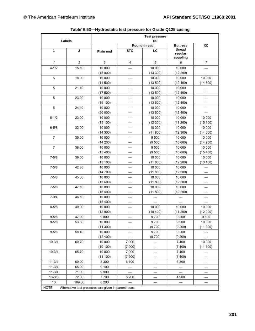
© The American Petroleum Institute API Standard 5CT/ISO 11960:2001
201
Table E.53—Hydrostatic test pressure for Grade Q125 casing
Test pressurepsiLabels
Round thread
1 2 Plain end STC LC
Buttressthreadregular
coupling
XC
1 2 3 4 5 6 7
4-1/2 15.10 10 000
(15 000)
Ñ
Ñ
10 000
(13 300)
10 000
(12 200)
Ñ
Ñ
5 18.00 10 000
(14 500)
Ñ
Ñ
10 000
(13 500)
10 000
(12 400)
10 000
(14 500)
5 21.40 10 000
(17 500)
Ñ
Ñ
10 000
(13 500)
10 000
(12 400)
Ñ
Ñ
5 23.20 10 000
(19 100)
Ñ
Ñ
10 000
(13 500)
10 000
(12 400)
Ñ
Ñ
5 24.10 10 000
(20 000)
Ñ
Ñ
10 000
(13 500)
10 000
(12 400)
Ñ
Ñ
5-1/2 23.00 10 000
(15 100)
Ñ
Ñ
10 000
(12 300)
10 000
(11 200)
10 000
(15 100)
6-5/8 32.00 10 000
(14 300)
Ñ
Ñ
10 000
(11 800)
10 000
(12 300)
10 000
(14 300)
7 35.00 10 000
(14 200)
Ñ
Ñ
9 500
(9 500)
10 000
(10 600)
10 000
(14 200)
7 38.00 10 000
(15 400)
Ñ
Ñ
9 500
(9 500)
10 000
(10 600)
10 000
(15 400)
7-5/8 39.00 10 000
(13 100)
Ñ
Ñ
10 000
(11 800)
10 000
(12 200)
10 000
(13 100)
7-5/8 42.80 10 000
(14 700)
Ñ
Ñ
10 000
(11 800)
10 000
(12 200)
Ñ
Ñ
7-5/8 45.30 10 000
(15 600)
Ñ
Ñ
10 000
(11 800)
10 000
(12 200)
Ñ
Ñ
7-5/8 47.10 10 000
(16 400)
Ñ
Ñ
10 000
(11 800)
10 000
(12 200)
Ñ
Ñ
7-3/4 46.10 10 000
(15 400)
Ñ
Ñ
Ñ
Ñ
Ñ
Ñ
Ñ
Ñ
8-5/8 49.00 10 000
(12 900)
Ñ
Ñ
10 000
(10 400)
10 000
(11 200)
10 000
(12 900)
9-5/8 47.00 9 800 Ñ 9 700 9 200 9 800
9-5/8 53.50 10 000
(11 300)
Ñ
Ñ
9 700
(9 700)
9 200
(9 200)
10 000
(11 300)
9-5/8 58.40 10 000
(12 400)
Ñ
Ñ
9 700
(9 700)
9 200
(9 200)
---
---
10-3/4 60.70 10 000
(10 100)
7 900
(7 900)
Ñ
Ñ
7 400
(7 400)
10 000
(11 100)
10-3/4 65.70 10 000
(11 100)
7 900
(7 900)
Ñ
Ñ
7 400
(7 400)
Ñ
Ñ
11-3/4 60.00 8 300 6 700 Ñ 6 300 Ñ
11-3/4 65.00 9 100 Ñ Ñ Ñ Ñ
11-3/4 71.00 9 900 Ñ Ñ Ñ Ñ
13-3/8 72.00 7 700 5 200 Ñ 4 900 Ñ
16 109.00 8 200 Ñ Ñ Ñ Ñ
NOTE Alternative test pressures are given in parentheses.

API Standard 5CT/ISO 11960:2001 © The American Petroleum Institute
202
Table E.54—Hydrostatic test pressure for Grade H40 tubing
LabelsTest pressure
psi
2 External upset
Special-clearancecoupling
1
NUT&C
EUT&C
IJ Plainend
Non-upsetT&C Regular
couplingH40 J55
Integraljoint
1 2 3 4 5 6 7 8 9 10
1.050 1.14 1.20 Ñ 6 900 6 900 6 900 Ñ Ñ Ñ
1.050 1.48 1.54 Ñ 9 400 Ñ 7 500 Ñ Ñ Ñ
1.315 1.70 1.80 1.72 6 500 6 500 6 500 Ñ Ñ 5 800
1.315 2.19 2.24 Ñ 8 700 Ñ 8 200 Ñ Ñ Ñ
1.660 2.09 Ñ 2.10 4 800 Ñ Ñ Ñ Ñ 4 600
1.660 2.30 2.40 2.33 5 400 5 400 5 400 Ñ Ñ 4 600
1.660 3.03 3.07 Ñ 7 400 Ñ 6 500 Ñ Ñ Ñ
1.900 2.40 Ñ 2.40 4 200 Ñ Ñ Ñ Ñ 4 100
1.900 2.75 2.90 2.76 4 900 4 900 4 900 Ñ Ñ 4 100
1.900 3.65 3.73 Ñ 6 700 Ñ 6 000 Ñ Ñ Ñ
2.063 3.24 Ñ 3.25 4 800 Ñ Ñ Ñ Ñ 4 100
2.063 4.50 Ñ Ñ 7 000 Ñ Ñ Ñ Ñ Ñ
2-3/8 4.00 Ñ Ñ 4 500 4 500 Ñ Ñ Ñ Ñ
2-3/8 4.60 4.70 Ñ 5 100 5 100 5 100 4 600 5 100 Ñ
2-7/8 6.40 6.50 Ñ 4 800 4 800 4 800 4 400 4 800 Ñ
3-1/2 7.70 Ñ Ñ 3 900 3 900 Ñ Ñ Ñ Ñ
3-1/2 9.20 9.30 Ñ 4 600 4 600 4 600 4 300 4 600 Ñ
3-1/2 10.20 Ñ Ñ 5 300 5 300 Ñ Ñ Ñ Ñ
4 9.50 Ñ Ñ 3 600 3 600 Ñ Ñ Ñ Ñ
4 10.70 11.00 Ñ 4 200 Ñ 4 200 Ñ Ñ Ñ
4-1/2 12.60 12.75 Ñ 3 900 3 900 3 900 Ñ Ñ Ñ

© The American Petroleum Institute API Standard 5CT/ISO 11960:2001
203
Table E.55—Hydrostatic test pressure for Grade J55 tubing
LabelsTest pressure
psi
2 External upset
Special-clearancecoupling
1
NUT&C
EUT&C
IJ Plainend
Non-upsetT&C
Regularcoupling
J55 N80
Integraljoint
1 2 3 4 5 6 7 8 9 10
1.050 1.14 1.20 Ñ 9 500 9 500 9 500 Ñ Ñ Ñ
1.050 1.48 1.54 Ñ 10 000 Ñ 10 000 Ñ Ñ Ñ
1.315 1.70 1.80 1.72 8 900 8 900 8 900 Ñ Ñ 8 000
1.315 2.19 2.24 Ñ 10 000 Ñ 10 000 Ñ Ñ Ñ
1.660 2.09 Ñ 2.10 6 600 Ñ Ñ Ñ Ñ 6 400
1.660 2.30 2.40 2.33 7 400 7 400 7 400 Ñ Ñ 6 400
1.660 3.03 3.07 Ñ 10 000 Ñ 9 000 Ñ Ñ Ñ
1.900 2.40 Ñ 2.40 5 800 Ñ Ñ Ñ Ñ 5 700
1.900 2.75 2.90 2.76 6 700 6 700 6 700 Ñ Ñ 5 700
1.900 3.65 3.73 Ñ 9 300 Ñ 8 300 Ñ Ñ Ñ
2.063 3.24 Ñ 3.25 6 700 Ñ Ñ Ñ Ñ 5 600
2.063 4.50 Ñ Ñ 9 600 Ñ Ñ Ñ Ñ Ñ
2-3/8 4.00 Ñ Ñ 6 200 6 200 Ñ Ñ Ñ Ñ
2-3/8 4.60 4.70 Ñ 7 000 7 000 7 000 6 300 7 000 Ñ
2-7/8 6.40 6.50 Ñ 6 600 6 600 6 600 6 100 6 600 Ñ
3-1/2 7.70 Ñ Ñ 5 400 5 400 Ñ Ñ Ñ Ñ
3-1/2 9.20 9.30 Ñ 6 400 6 400 6 400 5 900 6 400 Ñ
3-1/2 10.20 Ñ Ñ 7 300 7 300 Ñ Ñ Ñ Ñ
4 9.50 Ñ Ñ 5 000 5 000 Ñ Ñ Ñ Ñ
4 10.70 11.00 Ñ 5 800 Ñ 5 800 Ñ Ñ Ñ
4-1/2 12.60 12.75 Ñ 5 300 5 300 5 300 Ñ Ñ Ñ

API Standard 5CT/ISO 11960:2001 © The American Petroleum Institute
204
Table E.56—Hydrostatic test pressure for Grades N80 Type 1 and N80Q tubing
LabelsTest pressure
psi
2 External upset
Special-clearancecoupling
1
NUT&C
EUT&C
IJ Plainend
Non-upsetT&C
Regularcoupling
N80 P110
Integraljoint
1 2 3 4 5 6 7 8 9 10
1.050 1.14 1.20 Ñ 10 000 10 000 10 000 Ñ Ñ Ñ
1.050 1.48 1.54 Ñ 10 000 Ñ 10 000 Ñ Ñ Ñ
1.315 1.70 1.80 1.72 10 000 10 000 10 000 Ñ Ñ 10 000
1.315 2.19 2.24 Ñ 10 000 Ñ 10 000 Ñ Ñ Ñ
1.660 2.30 2.40 2.33 10 000 10 000 10 000 Ñ Ñ 9 300
1.660 3.03 3.07 Ñ 10 000 Ñ 10 000 Ñ Ñ Ñ
1.900 2.75 2.90 2.76 9 800 9 800 9 800 Ñ Ñ 8 200
1.900 3.65 3.73 Ñ 10 000 Ñ 10 000 Ñ Ñ Ñ
2.063 3.24 Ñ 3.25 9 700 Ñ Ñ Ñ Ñ 8 100
2.063 4.50 Ñ Ñ 10 000 Ñ Ñ Ñ Ñ Ñ
2-3/8 4.00 Ñ Ñ 9 000 9 000 Ñ Ñ Ñ Ñ
2-3/8 4.60 4.70 Ñ 10 000 10 000 10 000 9 100 10 000 Ñ
2-3/8 5.80 5.95 Ñ 10 000 10 000 10 000 9 100 10 000 Ñ
2-7/8 6.40 6.50 Ñ 9 700 9 700 9 700 8 800 9 700 Ñ
2-7/8 7.80 7.90 Ñ 10 000 10 000 10 000 8 800 10 000 Ñ
2-7/8 8.60 8.70 Ñ 10 000 10 000 10 000 8 800 10 000 Ñ
3-1/2 7.70 Ñ Ñ 7 900 7 900 Ñ Ñ Ñ Ñ
3-1/2 9.20 9.30 Ñ 9 300 9 300 9 300 8 500 9 300 Ñ
3-1/2 10.20 Ñ Ñ 10 000 10 000 Ñ Ñ Ñ Ñ
3-1/2 12.70 12.95 Ñ 10 000 10 000 10 000 8 500 10 000 Ñ
4 9.50 Ñ Ñ 7 200 7 200 Ñ Ñ Ñ Ñ
4 10.70 11.00 Ñ 8 400 Ñ 8 400 Ñ Ñ Ñ
4-1/2 12.60 12.75 Ñ 7 700 7 700 7 700 Ñ Ñ Ñ

© The American Petroleum Institute API Standard 5CT/ISO 11960:2001
205
Table E.57—Hydrostatic test pressure for Grade L80 tubing
LabelsTest pressure
psi
2 External upset1
NUT&C
EUT&C
IJ Plainend
Non-upsetT&C Regular
coupling
Special-clearancecoupling
Integraljoint
1 2 3 4 5 6 7 8 9
1.050 1.14 1.20 Ñ 10 000 10 000 10 000 Ñ Ñ
1.050 1.48 1.54 Ñ 10 000 Ñ 10 000 Ñ Ñ
1.315 1.70 1.80 1.72 10 000 10 000 10 000 Ñ 10 000
1.315 2.19 2.24 Ñ 10 000 Ñ 10 000 Ñ Ñ
1.660 2.30 2.40 2.33 10 000 10 000 10 000 Ñ 9 3001.660 3.03 3.07 Ñ 10 000 Ñ 10 000 Ñ Ñ
1.900 2.75 2.90 2.76 9 800 9 800 9 800 Ñ 8 200
1.900 3.65 3.73 Ñ 10 000 Ñ 10 000 Ñ Ñ
1.900 4.42 Ñ Ñ 10 000 Ñ Ñ Ñ Ñ
1.900 5.15 Ñ Ñ 10 000 Ñ Ñ Ñ Ñ
2.063 3.24 Ñ 3.25 9 700 Ñ Ñ Ñ 8 1002.063 4.50 Ñ Ñ 10 000 Ñ Ñ Ñ Ñ
2-3/8 4.00 Ñ Ñ 9 000 9 000 Ñ Ñ Ñ
2-3/8 4.60 4.70 Ñ 10 000 10 000 10 000 9 100 Ñ
2-3/8 5.80 5.95 Ñ 10 000 10 000 10 000 9 100 Ñ
2-3/8 6.60 Ñ Ñ 10 000 Ñ Ñ Ñ Ñ
2-3/8 7.35 7.45 Ñ 10 000 Ñ 10 000 9 100 Ñ
2-7/8 6.40 6.50 Ñ 9 700 9 700 9 700 8 800 Ñ
2-7/8 7.80 7.90 Ñ 10 000 10 000 10 000 8 800 Ñ
2-7/8 8.60 8.70 Ñ 10 000 10 000 10 000 8 800 Ñ
2-7/8 9.35 9.45 Ñ 10 000 Ñ 10 000 8 800 Ñ
2-7/8 10.50 Ñ Ñ 10 000 Ñ Ñ Ñ Ñ
2-7/8 11.50 Ñ Ñ 10 000 Ñ Ñ Ñ Ñ
3-1/2 7.70 Ñ Ñ 7 900 7 900 Ñ Ñ Ñ3-1/2 9.20 9.30 Ñ 9 300 9 300 9 300 8 500 Ñ
3-1/2 10.20 Ñ Ñ 10 000 10 000 Ñ Ñ Ñ
3-1/2 12.70 12.95 Ñ 10 000 10 000 10 000 8 500 Ñ
3-1/2 14.30 Ñ Ñ 10 000 Ñ Ñ Ñ Ñ
3-1/2 15.50 Ñ Ñ 10 000 Ñ Ñ Ñ Ñ
3-1/2 17.00 Ñ Ñ 10 000 Ñ Ñ Ñ Ñ
4 9.50 Ñ Ñ 7 200 7 200 Ñ Ñ Ñ4 10.70 11.00 Ñ 8 400 Ñ 8 400 Ñ Ñ
4 13.20 Ñ Ñ 10 000 Ñ Ñ Ñ Ñ
4 16.10 Ñ Ñ 10 000 Ñ Ñ Ñ Ñ
4 18.90 Ñ Ñ 10 000 Ñ Ñ Ñ Ñ
4 22.20 Ñ Ñ 10 000 Ñ Ñ Ñ Ñ
4-1/2 12.60 12.75 Ñ 7 700 7 700 7 700 Ñ Ñ
4-1/2 15.20 Ñ Ñ 9 600 Ñ Ñ Ñ Ñ4-1/2 17.00 Ñ Ñ 10 000 Ñ Ñ Ñ Ñ
4-1/2 18.90 Ñ Ñ 10 000 Ñ Ñ Ñ Ñ
4-1/2 21.50 Ñ Ñ 10 000 Ñ Ñ Ñ Ñ
4-1/2 23.70 Ñ Ñ 10 000 Ñ Ñ Ñ Ñ
4-1/2 26.10 Ñ Ñ 10 000 Ñ Ñ Ñ Ñ

API Standard 5CT/ISO 11960:2001 © The American Petroleum Institute
206
Table E.58—Hydrostatic test pressure for Grade C90 tubing
LabelsTest pressure
psi
21
NUT&C
EUT&C
IJPlainend
Non-upsetT&C
External upsetregular coupling
Integraljoint
1 2 3 4 5 6 7 8
1.050 1.14 1.20 Ñ 10 000 10 000 10 000 Ñ
1.050 1.48 1.54 Ñ 10 000 Ñ 10 000 Ñ
1.315 1.70 1.80 1.72 10 000 10 000 10 000 10 000
1.315 2.19 2.24 Ñ 10 000 Ñ 10 000 Ñ
1.660 2.30 2.40 2.33 10 000 10 000 10 000 10 0001.660 3.03 3.07 Ñ 10 000 Ñ 10 000 Ñ
1.900 2.75 2.90 2.76 10 000 10 000 10 000 9 200
1.900 3.65 3.73 Ñ 10 000 Ñ 10 000 Ñ
1.900 4.42 Ñ Ñ 10 000 Ñ Ñ Ñ
1.900 5.15 Ñ Ñ 10 000 Ñ Ñ Ñ
2.063 3.24 Ñ 3.25 10 000 Ñ Ñ 9 2002.063 4.50 Ñ Ñ 10 000 Ñ Ñ Ñ
2-3/8 4.00 Ñ Ñ 10 000 10 000 Ñ Ñ
2-3/8 4.60 4.70 Ñ 10 000 10 000 10 000 Ñ
2-3/8 5.80 5.95 Ñ 10 000 10 000 10 000 Ñ
2-3/8 6.60 Ñ Ñ 10 000 Ñ Ñ Ñ
2-3/8 7.35 7.45 Ñ 10 000 Ñ 10 000 Ñ
2-7/8 6.40 6.50 Ñ 10 000 10 000 10 000 Ñ
2-7/8 7.80 7.90 Ñ 10 000 10 000 10 000 Ñ
2-7/8 8.60 8.70 Ñ 10 000 10 000 10 000 Ñ
2-7/8 9.35 9.45 Ñ 10 000 Ñ 10 000 Ñ
2-7/8 10.50 Ñ Ñ 10 000 Ñ Ñ Ñ
2-7/8 11.50 Ñ Ñ 10 000 Ñ Ñ Ñ
3-1/2 7.70 Ñ Ñ 8 900 8 900 Ñ Ñ3-1/2 9.20 9.30 Ñ 10 000 10 000 10 000 Ñ
3-1/2 10.20 Ñ Ñ 10 000 10 000 Ñ Ñ
3-1/2 12.70 12.95 Ñ 10 000 10 000 10 000 Ñ
3-1/2 14.30 Ñ Ñ 10 000 Ñ Ñ Ñ
3-1/2 15.50 Ñ Ñ 10 000 Ñ Ñ Ñ
3-1/2 17.00 Ñ Ñ 10 000 Ñ Ñ Ñ
4 9.50 Ñ Ñ 8 100 8 100 Ñ Ñ4 10.70 11.00 Ñ 9 400 Ñ 9 400 Ñ
4 13.20 Ñ Ñ 10 000 Ñ Ñ Ñ
4 16.10 Ñ Ñ 10 000 Ñ Ñ Ñ
4 18.90 Ñ Ñ 10 000 Ñ Ñ Ñ
4 22.20 Ñ Ñ 10 000 Ñ Ñ Ñ
4-1/2 12.60 12.75 Ñ 8 700 8 700 8 700 Ñ
4-1/2 15.20 Ñ Ñ 10 000 Ñ Ñ Ñ4-1/2 17.00 Ñ Ñ 10 000 Ñ Ñ Ñ
4-1/2 18.90 Ñ Ñ 10 000 Ñ Ñ Ñ
4-1/2 21.50 Ñ Ñ 10 000 Ñ Ñ Ñ
4-1/2 23.70 Ñ Ñ 10 000 Ñ Ñ Ñ
4-1/2 26.10 Ñ Ñ 10 000 Ñ Ñ Ñ

© The American Petroleum Institute API Standard 5CT/ISO 11960:2001
207
Table E.59—Hydrostatic test pressure for Grade T95 tubing
LabelsTest pressure
psi
21
NUT&C
EUT&C
IJPlainend
Non-upsetT&C
External upsetregular
coupling
Integraljoint
1 2 3 4 5 6 7 8
1.050 1.14 1.20 Ñ 10 000 10 000 10 000 Ñ
1.050 1.48 1.54 Ñ 10 000 Ñ 10 000 Ñ
1.315 1.70 1.80 1.72 10 000 10 000 10 000 10 000
1.315 2.19 2.24 Ñ 10 000 Ñ 10 000 Ñ
1.660 2.30 2.40 2.33 10 000 10 000 10 000 10 000
1.660 3.03 3.07 Ñ 10 000 Ñ 10 000 Ñ
1.900 2.75 2.90 2.76 10 000 10 000 10 000 9 800
1.900 3.65 3.73 Ñ 10 000 Ñ 10 000 Ñ
1.900 4.42 Ñ Ñ 10 000 Ñ Ñ Ñ
1.900 5.15 Ñ Ñ 10 000 Ñ Ñ Ñ
2.063 3.24 Ñ 3.25 10 000 Ñ Ñ 9 700
2.063 4.50 Ñ Ñ 10 000 Ñ Ñ Ñ
2-3/8 4.00 Ñ Ñ 10 000 10 000 Ñ Ñ
2-3/8 4.60 4.70 Ñ 10 000 10 000 10 000 Ñ
2-3/8 5.80 5.95 Ñ 10 000 10 000 10 000 Ñ
2-3/8 6.60 Ñ Ñ 10 000 Ñ Ñ Ñ2-3/8 7.35 7.45 Ñ 10 000 Ñ 10 000 Ñ
2-7/8 6.40 6.50 Ñ 10 000 10 000 10 000 Ñ
2-7/8 7.80 7.90 Ñ 10 000 10 000 10 000 Ñ
2-7/8 8.60 8.70 Ñ 10 000 10 000 10 000 Ñ
2-7/8 9.35 9.45 Ñ 10 000 Ñ 10 000 Ñ
2-7/8 10.50 Ñ Ñ 10 000 Ñ Ñ Ñ
2-7/8 11.50 Ñ Ñ 10 000 Ñ Ñ Ñ
3-1/2 7.70 Ñ Ñ 9 400 9 400 Ñ Ñ
3-1/2 9.20 9.30 Ñ 10 000 10 000 10 000 Ñ
3-1/2 10.20 Ñ Ñ 10 000 10 000 Ñ Ñ
3-1/2 12.70 12.95 Ñ 10 000 10 000 10 000 Ñ
3-1/2 14.30 Ñ Ñ 10 000 Ñ Ñ Ñ
3-1/2 15.50 Ñ Ñ 10 000 Ñ Ñ Ñ
3-1/2 17.00 Ñ Ñ 10 000 Ñ Ñ Ñ
4 9.50 Ñ Ñ 8 600 8 600 Ñ Ñ
4 10.70 11.00 Ñ 10 000 Ñ 10 000 Ñ
4 13.20 Ñ Ñ 10 000 Ñ Ñ Ñ
4 16.10 Ñ Ñ 10 000 Ñ Ñ Ñ
4 18.90 Ñ Ñ 10 000 Ñ Ñ Ñ
4 22.20 Ñ Ñ 10 000 Ñ Ñ Ñ
4-1/2 12.60 12.75 Ñ 9 200 9 200 9 200 Ñ
4-1/2 16.20 Ñ Ñ 10 000 Ñ Ñ Ñ
4-1/2 17.00 Ñ Ñ 10 000 Ñ Ñ Ñ
4-1/2 18.90 Ñ Ñ 10 000 Ñ Ñ Ñ
4-1/2 21.50 Ñ Ñ 10 000 Ñ Ñ Ñ
4-1/2 23.70 Ñ Ñ 10 000 Ñ Ñ Ñ
4-1/2 26.10 Ñ Ñ 10 000 Ñ Ñ Ñ

API Standard 5CT/ISO 11960:2001 © The American Petroleum Institute
208
Table E.60—Hydrostatic test pressure for Grade P110 tubing
LabelsTest pressure
psi
1 2 External upset
NUT&C
EUT&C
Plainend
Non-upsetT&C
Regularcoupling
Special-clearancecoupling
1 2 3 4 5 6 7
1.050 1.48 1.54 10 000
(25 800)
Ñ
Ñ
10 000
(20 700)
Ñ
Ñ
1.315 2.19 2.24 10 000
(24 000)
Ñ
Ñ
10 000
(22 500)
Ñ
Ñ
1.660 3.03 3.07 10 000
(20 300)
Ñ
Ñ
10 000
(18 000)
Ñ
Ñ
1.900 3.65 3.73 10 000
(18 500)
Ñ
Ñ
10 000
(16 600)
Ñ
Ñ
2.063 4.50 Ñ 10 000
(19 200)
Ñ
Ñ
Ñ
Ñ
Ñ
Ñ
2-3/8 4.60 4.70 10 000
(14 100)
10 000
(14 100)
10 000
(14 100)
10 000
(12 600)
2-3/8 5.80 5.95 10 000
(18 800)
10 000
(17 700)
10 000
(16 300)
10 000
(12 600)
2-7/8 6.40 6.50 10 000
(13 300)
10 000
(13 300)
10 000
(13 300)
10 000
(12 100)
2-7/8 7.80 7.90 10 000
(16 900)
10 000
(16 900)
10 000
(16 400)
10 000
(12 100)
2-7/8 8.60 8.70 10 000
(18 900)
10 000
(18 300)
10 000
(16 400)
10 000
(12 100)
3-1/2 9.20 9.30 10 000
(12 800)
10 000
(12 800)
10 000
(12 800)
10 000
(11 700)
3-1/2 12.70 12.95 10 000
(18 900)
10 000
(18 000)
10 000
(17 200)
10 000
(11 700)
NOTE Alternative test pressures are given in parentheses.

© The American Petroleum Institute API Standard 5CT/ISO 11960:2001
209
Table E.61—Summary of NDE methods for seamless and the body of welded pipe
GradeVisual
Inspection(see 10.14)
Wall thicknessdetermination
Ultrasonicinspection
Flux leakageinspection
Eddy currentinspection
Magnetic particleInspection a
1 2 3 4 5 6 7
H40 J55
K55 N80 Type 1
R N N N N N
N80Q L80
C95 M65
R R A A A A
P110 R R A A A NA
C90 T95 Q125 R R C B B B
N = not required
R = required
A = one method or any combination of methods shall be used
B = at least one method shall be used in addition to ultrasonic inspection to inspect the outside surface
C = ultrasonic inspection shall be used to inspect the outside and inside surface
NA = not applicablea MPI is permitted for end-area inspection. MPI is permitted for pipe-body outside-surface inspection in combination with othermethods of pipe body inspection.
Table E.62—Acceptance (inspection) levels
External imperfection Internal imperfectionGrade
Longitudinal Transverse Longitudinal Transverse
1 2 3 4 5
N80Q M65 L80 C95 L4 Ñ L4 Ñ
P110 to A.9 (SR16) L4 L4 L4 L4
P110 L2 L2 L2 L2
P110 to A.9Ê(SR16) and A.2Ê(SR2) L2 L2 L2 L2
C90 UT L2 L2 L2 L2
T95-Q125 2nd method L2 L2 Ñ Ñ
Weld seam
P110 Q125 L2 N L2 N
All other grades L3 N L3 N
N = not required, Lx = acceptance (inspection) level
Table E.63—Artificial reference indicators
Acceptance(inspection) level
Notch depth a
max.%
Notch lengthmax. at full depth
in
Widthmax.
in
Radially drilled holediameter b
in
1 2 3 4 5
L2 5 2.0 0.040 1/16
L3 10 2.0 0.040 1/8
L4 12.5 2.0 0.040 1/8a Depth as a percent of specified wall thickness. The depth tolerance shall be ± 15Ê% of the calculated notch depth, with a minimumnotch depth of 0.012 in ± 0.002 in.b Drilled hole diameter (through the pipe wall) shall be based on the drill bit size.
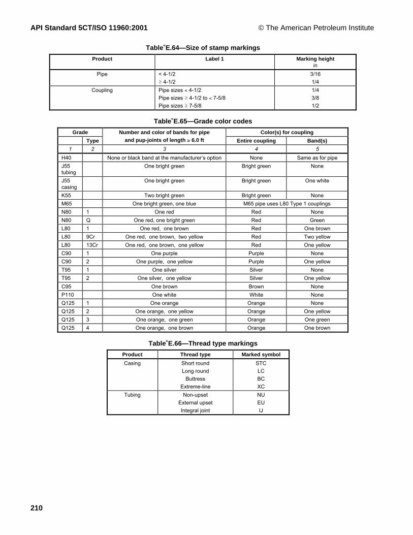
API Standard 5CT/ISO 11960:2001 © The American Petroleum Institute
210
Table E.64—Size of stamp markings
Product Label 1 Marking heightin
Pipe < 4-1/2
³ 4-1/2
3/16
1/4
Coupling Pipe sizes < 4-1/2
Pipe sizes ³ 4-1/2 to < 7-5/8
Pipe sizes ³ 7-5/8
1/4
3/8
1/2
Table E.65—Grade color codes
Grade Color(s) for coupling
Type
Number and color of bands for pipeand pup-joints of length ³ 6.0 ft Entire coupling Band(s)
1 2 3 4 5
H40 None or black band at the manufacturerÕs option None Same as for pipe
J55tubing
One bright green Bright green None
J55casing
One bright green Bright green One white
K55 Two bright green Bright green None
M65 One bright green, one blue M65 pipe uses L80 Type 1 couplings
N80 1 One red Red None
N80 Q One red, one bright green Red Green
L80 1 One red, one brown Red One brown
L80 9Cr One red, one brown, two yellow Red Two yellow
L80 13Cr One red, one brown, one yellow Red One yellow
C90 1 One purple Purple None
C90 2 One purple, one yellow Purple One yellow
T95 1 One silver Silver None
T95 2 One silver, one yellow Silver One yellow
C95 One brown Brown None
P110 One white White None
Q125 1 One orange Orange None
Q125 2 One orange, one yellow Orange One yellow
Q125 3 One orange, one green Orange One green
Q125 4 One orange, one brown Orange One brown
Table E.66—Thread type markings
Product Thread type Marked symbol
Casing Short round
Long round
Buttress
Extreme-line
STC
LC
BC
XC
Tubing Non-upset
External upset
Integral joint
NU
EU
IJ

© The American Petroleum Institute API Standard 5CT/ISO 11960:2001
211
Table E.67—Marking requirements and sequence
Stencil and/or stamp marking requirements a
Groups 1 and 3 Groups 2 and 4
Marking sequence Mark orsymbol b
Pipe andpup-joints
Couplingsand
accessories
Pipe andpup-joints
Couplingsand
accessories1 2 3 4 5 6 71 ManufacturerÕs name or mark ..... D or P D or P P P2 ISOÊspecification marking plus compatible
standard at manufacturer's option or as specifiedon purchase agreement. Inclusion of ÒAPIÓ inmarking is at manufacturer's option.Date of manufacture as in 11.1.8 or 11.1.9.
ISOÊ11960API 5CT
D or P D or P P P
3 Unthreaded pipe or special end finish, ifapplicable(place symbol after specification marking):Ñ Unthreaded pipe either upset or non-upsetÑ Pipe threaded with special end finishÑ Completed couplings or completed
accessories with special end finish
UFSF
SF
D or PD or P
D or P
PPP
P4 Size designation (fill in Label 1 designation from
column 1 of Tables E.1 E.2 or E.3)..... P P
5 Mass designation(fill in Label 2 designation from column 2 ofTables E.1 E.2 or E.3) ..... D or P P
6 Grade of pipeH40J55K55N80 Type 1N80QM65L80P110C95L80 Type9CrL80 Type13CrC90 Type1C90 Type2T95 Type1T95 Type2Q125 Type1Q125 Type2Q125 Type3Q125 Type4All grade designations
HJK
N1NQMLPCL9L13
C90-1C90-2T95-1T95-2
Q1Q2Q3Q4
D or P D c or P P P7 Reduced alternative impact test temperature, if
applicable. Fill in specified test temperature forfull-size specimens including ± symbol and ¡F
.....F P P P P
8 Heat treatment, if applicableÑ J55, K55 or M65 normalizedÑ J55, K55 or M65
ZQ
PP
PP
PP
PP
9 Process of manufactureÑ SeamlessÑ Electric-weldedAll designations
SE
D or P P10 Supplementary requirements, if applicable:
A.1 (SR1)A.2 (SR2)A.3 (SR9) (fill in type)A.7 (SR13)A.9 (SR16) (fill in minimum full size energyabsorption requirement in ft.lb and testtemperature, including ± symbol and ¡F)
S1S2
S9Q.....S13.....
S16.....F
PP
P
D or P
PP
P
PP
11 Hydrostatic test pressure d
(fill in the actual test pressure in psi)
All designations P..... P P
See end of table for notes.

API Standard 5CT/ISO 11960:2001 © The American Petroleum Institute
212
Table E.67 (continued )
Stencil and/or stamp marking requirements a
Groups 1 and 3 Groups 2 and 4
Marking sequence Mark orsymbol b
Pipe andpup-joints
Couplingsand
accessories
Pipe andpup-joints
Couplingsand
accessories
1 2 3 4 5 6 7
12 Type of thread, if applicable:
Ñ For manufacturers, processors orthreaders of casing buttress extreme-line orround threads (fill in type of thread fromTableÊÊE.66)
Ñ For threaders of tubing threads (fill in typeof thread from Table E.66)
.....
.....
P
P
P
P
13 Full length drift test, if applicable
Ñ Standard (casing or tubing)
Ñ Alternative (casing or tubing) where ÒxxÓ is the size of the alternative drift.
For casing specified for tubing service and drifttested in accordance with 8.10All designations
D
DAxx
DT42
P P
14 Serialization of Grades C90 T95 and Q125 D c or P D c or P
15 Tin plating of couplings, if applicable T P P
16 Couplings H40, J55 and K55 only visuallyinspected
V P
NOTE See 11.4 for mandatory color code requirements.a D is for optional (die) stamping; P is a requirement for (paint) stenciling. Optional marking is permitted as specified in 11.1and 11.2.b A blank space ÇÊ.....ÊÈ indicates information to be filled in.c Stamp marking shall conform to the requirements of 11.2.5.d Pipe can be identified as manufactured to SI units by the marked hydro-test pressure which will be less than 100 (MPa), whilethe pressure marked for pipe manufactured to USC units will be over 1Ê000 (psi). This information is used to clearly identify theunits used for CVN markings, which shall be in the same unit system as the pressure markings.
Table E.68—Retention of records
Requirement Subclause reference
Chemical propertiesHeat analysis
Product analysis
10.3.2
10.3.3
Mechanical propertiesTensile tests
Control tests
Impact tests
Couplings
Hardness tests
Hardenability test (Grades C90 and T95)
7.2, 10.4.7
10.4.2
7.4, 7.5, 7.6 , 10.7
9.5
7.7, 7.8, 7.9 and 10.6
7.10, 10.9
Hydrostatic testsTester recorder charts
Testing
10.12.1
10.12.1
Manufacturer certificationResults of all required tests (Group 4)
Sulfide stress cracking test (Grades C90 and T95)
Calibration
13.3
7.14, 10.10
Various

© The American Petroleum Institute API Standard 5CT/ISO 11960:2001
213
Table E.69—SR11.1 Distance between plates for flattening tests
D/t ratioDistance between plates
max.in
P110
Q125
All ratios
All ratios
D ´ (1.086 Ð 0.016Ê3 D/t)
D ´ (1.092 Ð 0.014Ê0 D/t)
D is the specified outside diameter of pipe, in inches.
t is the specified wall thickness of the pipe, in inches.
Table E.70—SR12.1 Inspection lot sample sizes vs. F factor
Sample size F Sample size F
1 2 3 4
3
4
5
6
7
8
9
10
12
14
13.857
9.215
7.501
6.612
6.061
5.686
5.414
5.203
4.900
4.690
16
18
20
25
30
35
40
45
50
¥
4.534
4.415
4.319
4.143
4.022
3.937
3.866
3.811
3.766
3.090
Table E.71—SR12.2 Probability of defective pipes
Probability of one length being defectiveProbability that one or more defective lengths
is included in a string of 100 pipes
1/10
1/100
1/1 000
1/10 000
0.999Ê97 (or 100Ê%)
0.634 (or 63Ê%)
0.095 (or 10Ê%)
0.009Ê95 (or 1Ê%)
Table E.72—SR16.1 Transverse impact specimen size required
Label 1Calculated wall thickness required to machine
transverse Charpy impact specimensin
Full size 3/4-size 1/2-size
1 2 3 4
3-1/24
4-1/25
5-1/26-5/8
77-5/87-3/48-5/89-5/810-3/411-3/413-3/8
1618-5/8
20
0.8090.7520.7120.6810.6560.6160.6060.5910.5880.5720.5570.5440.5350.5220.5080.4970.493
0.7110.6540.6140.5830.5580.5180.5080.4930.4900.4740.4590.4460.4370.4240.4100.3990.395
0.6120.5550.5150.4840.4590.4190.4090.3940.3910.3750.3600.3470.3380.3250.3110.3000.296
NOTE The wall thicknesses in columns 2, 3 and 4 that are in excess of the maximumwall thicknesses are for information only. The above provides a 0.020 in ID and a 0.020 inOD machining allowance.

API Standard 5CT/ISO 11960:2001 © The American Petroleum Institute
214
Table E.73—SR16.2 Longitudinal impact specimen size required
Calculated wall thickness required to machinelongitudinal Charpy impact specimens
inLabel 1
Full size 3/4-size 1/2-size
1 2 3 4
1 050
1 315
1 660
1 900
2 063
2-3/8
2-7/8
3-1/2
4
4-1/2
5
5-1/2
6-5/8
7
7-5/8
7-3/4
8-5/8
9-5/8
10-3/4
11-3/4
13-3/8
16
18-5/8
20
0.472
0.464
0.458
0.455
0.453
0.450
0.448
0.445
0.444
0.443
0.442
0.441
0.440
0.440
0.439
0.439
0.439
0.438
0.438
0.437
0.437
0.436
0.436
0.436
0.374
0.366
0.360
0.357
0.355
0.352
0.350
0.347
0.346
0.345
0.344
0.343
0.342
0.342
0.341
0.341
0.341
0.340
0.340
0.339
0.339
0.338
0.338
0.338
0.275
0.267
0.261
0.258
0.256
0.253
0.251
0.248
0.247
0.246
0.245
0.244
0.243
0.243
0.242
0.242
0.242
0.241
0.241
0.240
0.240
0.239
0.239
0.239
NOTE The wall thicknesses in columns 2, 3 and 4 that are in excess of themaximum wall thicknesses are for information only. The above provides a 0.020 in IDand a 0.020 in OD machining allowance.
Table E.74—SR16.3 Acceptable size impact specimens and absorbed energy reduction factor
Test specimen sizeSpecimen dimensions
mmReduction factor
Full size 10.0 ´ 10.0 1.00
3/4-size 10.0 ´ 7.5 0.80
1/2-size 10.0 ´ 5.0 0.55
Table E.75—SR16.4 Hierarchy of test specimen orientation and size
Choice Orientation Size
1st
2nd
3rd
4th
5th
6th
Transverse
Transverse
Transverse
Longitudinal
Longitudinal
Longitudinal
Full size
3/4-size
1/2-size
Full size
3/4-size
1/2-size

© The American Petroleum Institute API Standard 5CT/ISO 11960:2001
215
Table E.76—SR16.5 Transverse Charpy absorbed energy requirements—Grade N80 Type 1
Maximum specified wall thicknessin
Minimum transverse absorbed energyft.lb
0.442 10
0.524 11
0.606 12
0.689 13
0.771 14
0.853 15
0.935 16
1.018 17
NOTE Wall thickness greater than standard ISO/API pipe are shown here forinformation for special applications. For wall thickness greater than shown above,the requirements shall be according to the equations for the wall thickness andgrade.
Table E.77—SR16.6 Longitudinal Charpy absorbed energy requirements—Grade N80 Type 1
Maximum specified wall thicknessin
Minimum longitudinal absorbed energyft.lb
0.421 20
0.462 21
0.504 22
0.545 23
0.586 24
0.627 25
0.668 26
0.709 27
0.750 28
0.791 29
0.833 30
0.874 31
0.915 32
0.956 33
0.997 34
1.038 35
NOTE Wall thicknesses greater than standard ISO/API pipe are shown here forinformation for special applications. For wall thickness greater than shown above, therequirements shall be according to the equations for the wall thickness and grade.
Table E.78—SR16.7 Test temperature reduction for sub-size specimens—Grades H40, J55 and K55 only
Specimen size Specified pipe wall thickness Temperature reductionmm in °F
10.0 ´ 7.5 > 0.394 5
10.0 ´ 5.0 > 0.394 20
10.0 ´ 5.0 0.295 to 0.394 15
10.0 ´ 5.0 0.264 to 0.291 10
10.0 ´ 5.0 0.236 to 0.260 5

API Standard 5CT/ISO 11960:2001 © The American Petroleum Institute
216
Table E.79—Marking instructions for API licensees (see annex F)
Stencil and/or stamp marking requirements a
Groups 1 and 3 Groups 2 and 4
Marking sequence Mark orsymbol b
Pipe andpup-joints
Couplingsand
accessories
Pipe andpup-joints
Couplingsand
accessories
1 2 3 4 5 6 7
1 Licensed manufacturerÕs name or mark(optional; neither is required)
..... D or P D or P P P
2 ISO specification marking plus compatiblestandard at manufacturer's option or as specifiedon purchase agreement. Inclusion of ÒAPIÓ inmarking is at manufacturer's optionManufacturerÕs option e:
API licence numberAPI monogramDate of manufacture as in F.1.8 or F.1.9
ISOÊ11960APIÊ5CT
.....
.....
.....
As specifiedD or P
As specifiedD or P
As specifiedP
As specifiedP
3 Unthreaded pipe or special end finish, ifapplicable (place symbol after specificationmarking):Ñ Unthreaded pipe either upset or non-upsetÑ Pipe threaded with special end finishÑ Completed couplings or completedaccessories with special end finish
UFSF
SF
D or PD or P
D or P
PP
P
4 Size designation (fill in Label 1 designation fromcolumn 1 of Tables E.1, E.2 or E.3)
..... P P
5 Mass designation (fill in Label 2 designation from column 2 ofTables E.1, E.2 or E.3) D or P P
6 Grade of pipe:H40J55K55N80 Type 1N80QM65L80P110C95L80 Type9CrL80 Type13CrC90 Type1C90 Type2T95 Type1T95 Type2Q125 Type1Q125 Type2Q125 Type3Q125 Type4
All grade designations
HJK
N1NQMLPCL9L13
C90-1C90-2T95-1T95-2
Q1Q2Q3Q4
D or P D or P P P7 Reduced alternative impact test temperature, if
applicable. Fill in specified test temperature forfull size specimens, including ± symbol and ¡F:
.....F P P P P
8 Heat treatment, if applicable:Ñ J55, K55 or M65 normalizedÑ J55, K55 or M65
ZQ
PP
PP
PP
PP
9 Process of manufactureÑ SeamlessÑ Electric-weldedAll designations
SE
D or P P10 Supplementary requirements, if applicable:
Ñ A.1 (SR1)Ñ A.2 (SR2)Ñ A.3 (SR9) (fill in type)Ñ A.7 (SR13)Ñ A.9 (SR16) (fill in minimum full-size energyabsorption requirement, in ft-lb, and testtemperature including ± symbol and ¡F)
S1S2
S9Q.....S13.....
S16.....F
PP
P
D or P
PP
P
PP

© The American Petroleum Institute API Standard 5CT/ISO 11960:2001
217
Table E.79 (continued)
Stencil and/or stamp marking requirements a
Groups 1 and 3 Groups 2 and 4
Marking sequence Mark orsymbol b
Pipe andpup-joints
Couplingsand
accessories
Pipe andpup-joints
Couplingsand
accessories
1 2 3 4 5 6 7
11 Hydrostatic test pressure d
(fill in the actual test pressure in psi)
All designations P..... P P
12 Type of thread, if applicable:
1. For manufacturers, processors or threadersof casing buttress, extreme-line or roundthreads
(fill in type of thread from TableÊE.66)
2. For threaders of tubing threads (fill in type ofthread from Table E.66)
.....
.....
P
P
P
P
13 Full length drift test, if applicable:
Ñ Standard (casing or tubing)
Ñ Alternative (casing or tubing) where ÇÊxxÊÈis the size of the alternative drift.
Ñ For casing specified for tubing service anddrift tested in accordance with 8.10All designations
D
DAxx
DT42
P P
14 Serialization of Grades C90, T95 and Q125 D c or P D c or P
15 Tin plating of couplings, if applicable T P P
16 Couplings H40, 55 and K55
only visually inspected
V P
NOTE See F.4 for mandatory color code requirements.a D is for optional (die) stamping; P is a requirement for (paint) stenciling. Optional marking is permitted as specified in clausesF.1 and F.2.b A blank space, ÇÊ.....ÊÈ, indicates information to be filled in.c Stamp marking shall conform to the requirements of F.2.5.d Pipe can be identified as manufactured to SI units by the marked hydro-test pressure which will be less than 100 (MPa), whilethe pressure marked for pipe manufactured to USC units will be over 1Ê000 (psi). This information is used to clearly identify theunits used for CVN markings, which shall be in the same unit system as the pressure markings.e If the licensee chooses to mark the API monogram, the licence number and date of manufacture shall also be marked.

API Standard 5CT/ISO 11960:2001 © The American Petroleum Institute
218
Annex F(informative)
Marking instructions for API licensees
F.1 General
F.1.1 Products manufactured in conformance with this International Standard may be marked by the APIlicensee as specified in clause 11 in the body of this International Standard or as specified in this annex. Productsto which the API monogram is applied shall be marked according to this annex.
F.1.2 For all manufacturers except threaders, the marking instructions in this annex, except those in F.6, areapplicable. For threaders the marking instructions in F.5 and F.6 and Tables C.79 or Table E.79 are applicable.Processors shall remove any identity that is not indicative of the new condition of the product as a result of heattreating (for example, prior grade identity and original pipe manufacturer’s name or logo).
F.1.3 Products shall be color-coded as specified in F.4.
F.1.4 Products shall be marked by stencilling, or a combination of stencilling and stamping, at the option of themanufacturer, as stipulated, with two exceptions:
¾ by agreement between purchaser and manufacturer, stamping can be required, in which case a combination ofstamping and stencil marking shall be used;
¾ at the option of the manufacturer, hot-rolled or hot-stamped markings on pipe and couplings may besubstituted for die-stamped markings and are permitted at intervals along the length.
F.1.5 Requirements for optional stamp markings are specified in F.2, and stencil markings shall be as specifiedin F.3. Marking instructions and sequence of markings are specified in Table C.79 or Table E.79, which includesonly those items that are stamped or stencilled for product identification. Examples of markings are shown inFigure D.23. If die-stamp marking is selected, it is not required to also stencil-mark the information. Marking shallnot overlap and shall be applied in such a manner as not to injure the pipe.
F.1.6 Additional markings, including those for compatible standards following the required marking sequence, areallowed and may be applied as desired by the manufacturer or as requested by the purchaser.
F.1.7 In a circumstance where it is necessary to re-mark pipe with the original marking information, the accuracyand traceability of the transferred markings shall be the responsibility of the entity re-marking the pipe. Thetransferred markings shall include the words "transferred by".
F.1.8 The complete monogram consists of the following: “5CT”, license number of the plant doing themanufacturing, the API monogram, and the date of manufacture. The date of manufacture is defined as a minimumof a two-digit number representing the last digit of the year and the calendar quarter in which the monogram isapplied.
F.1.9 Products manfactured in accordance with this second edition of ISO 11960 during the period of overlap ofapplication (see Foreword) with the first edition may be identified either by using “0” as the overlap perioddesignation, rather than the quarter, or by other appropriate markings using the provisions of 11.1.6. The overlapperiod designation “0” applies to the pipe body characteristics and does not apply to changes in ISO 10422 or APISpec 5B.

© The American Petroleum Institute API Standard 5CT/ISO 11960:2001
219
F.2 Stamp marking requirements
F.2.1 Methods
Methods of stamp marking shall be as follows:
Number Stamping method
1 Hot-rolled or hot-stamped markings
2 Cold die stamping with standard dies
3 Cold die stamping with interrupted dot face dies
4 Cold die stamping with rounded-face dies
5 Vibratory
After stamp marking, Group 2 and Group 4 products may require subsequent heat treatment as specified in F.2.5.Such heat treatment shall be in accordance with 6.2 of the body of this International Standard. The sequence ofstamp markings shall be as shown in TableÊC.79 or Table E.79.
F.2.2 Size
Sizes of stamp markings shall be as shown in Table C.64 or Table E.64.
F.2.3 Location
Placements of these markings on casing, liners and tubing sizes Label 1: 1.660 and larger shall be on the outsidesurface of each length within 300 mm (12 in) from the coupling or box, either end of plain-end pipe or either end ofpin-by-pin threaded pipe. The optional stamp marking on sizes smaller than Label 1: 1.660 may be on a metal tagaffixed to each length or, for bundled tubing, stamped on a metal tag affixed to each bundle.
F.2.4 Groups 1 and 3
When specified on the purchase agreement, products shall be stamped by one or more of the methods in F.2.1 atthe option of the manufacturer.
F.2.5 Groups 2 and 4
When specified on the purchase agreement, products may be stamped by one or more of the methods in F.2.1 atthe option of the manufacturer.
Group 2 (except Grades C90 and T95) shall be heat-treated subsequent to using method 2 in F.2.1.
Group 2 ( Grades C90 and T95 only) and Group 4 products shall be heat-treated subsequent to using methods 2andÊ4 in F.2.1, with the following exceptions:
¾ the make-up triangle mark;
¾ when the stamp markings are removed by grinding, machining, threading or cropping to a depth not less thantwice the depth of the stamping;
¾ when not removing the stamping is by agreement between purchaser and manufacturer.

API Standard 5CT/ISO 11960:2001 © The American Petroleum Institute
220
F.2.6 Make-up triangle marking
For buttress casing in all sizes and grades and for round thread casing in sizes LabelÊ1: 16 and larger in GradesH40, J55, K55 and M65, the make-up triangle shall be stamped on the outside of each length on both ends. Byagreement between purchaser and manufacturer, the make-up triangle may be replaced with a transverse whitepaint band 10Êmm (3/8 in) wide by 76Êmm (3 in) long. To assist in locating the triangle or transverse white paintband on buttress casing, a 25Êmm (1Êin) wide by 610 mm (24 in) long longitudinal white paint stripe shall be placedadjacent to the triangle or transverse paint band on the field end; additionally, a 25Êmm (1Êin) wide by 100Êmm (4Êin)long longitudinal white paint stripe shall be placed adjacent to the triangle or transverse paint band on the mill end.
For Groups 1 and 3, the triangle shall be stamped by method 2 or 4 only.
For Group 2 ( Grades C90 and T95 only), the triangle shall be stamped by method 3 only.
For Group 2 ( except Grades C90 and T95) and Group 4, the triangle shall be stamped by method 3 or 4 only.
F.3 Stencil marking requirements
Stencilled markings shall be placed on the outside surface of each length of pipe starting not less than 0,6 m (24 in)from the coupling or box or from either end of plain-end pipe or either end of pin-by-pin threaded pipe. Foraccessories and pup-joints less than 1,8 m (6 ft) in length, the required stencil markings may be placed on a decalattached to the outside surface within 0,3 m (12 in) of the end. These markings shall be separated by a dash orshall be adequately spaced.
The sequence of stencil markings shall be as specified in Table C.79 or Table E.79, except the thread markingshall be at a location convenient to the manufacturer.
F.4 Color identification
F.4.1 Color coding
Each product shall be color-coded as described in F.4.2 to F.4.6, unless otherwise specified on the purchaseagreement:
F.4.2 Pipe and pup-joints 1,8 m (6 ft) and longer
One or more of the following methods shall be used.
a) Paint a band encircling the pipe at a distance not greater than 0,6 m (24 in) from the coupling or box or eitherend of plain-end or pin-by-pin threaded pipe.
b) Paint the entire outside surface of the coupling, including the appropriate coupling color bands.
c) If the pipe is furnished with special-clearance couplings or if the pipe and couplings are of a different grade(except Grades H40, J55 and K55 applied in accordance with 9.2.1 of this International Standard), paint both thepipe and couplings as specified in a) and b) above.
F.4.3 Loose couplings
Paint the entire surface of the coupling, including the appropriate color bands.
F.4.4 Pup-joints and accessories shorter than 1,8 m (6 ft) in length
Paint the entire surface except the threads, including the appropriate color bands.

© The American Petroleum Institute API Standard 5CT/ISO 11960:2001
221
F.4.5 Special-clearance couplings
Paint the colors indicative of the steel grade from which the couplings are manufactured and also paint a blackband around the centre.
F.4.6 Grade color codes
The color and number of bands for each grade shall be as shown in Table C.65 or Table E.65
F.5 Thread and end finish marking—All groups
F.5.1 ISO/API thread marking
For manufacturers, thread identification shall be stencilled on casing with round, buttress or extreme-line threads.For threaders, thread identification is required on casing and tubing. This thread identification shall be as shown inTableÊC.66 or Table E.66.
F.5.2 Unfinished and special end-finish markings
Different marking is required for
a) plain-end pipe furnished either upset or non-upset or
b) pipe with special end-finish not specified herein but having the body of the pipe manufactured in accordancewith the requirements specified herein or
c) completed couplings and completed accessories furnished with special end-finish not specified herein butwhich meet all the other requirements specified herein for these products except dimensions.
This marking shall be as shown in TableÊC.79 or Table E.79.
F.6 Pipe threader marking requirements—All groups
Pipe threaded by a facility other than the original pipe manufacturer shall be identified by a stamp or stencilconsistent with clauses F.1, F2 and F.3 adjacent to the threads with the name or mark of the threader, thespecification mark, and size and type of thread as listed in clause F.5 and Table C.66 or Table E.66.
The threader shall mark on the body of the pipe the actual hydrostatic test pressure, unless the pipe has beenpreviously tested to the pressure required for the thread as shown in Tables C.44 to C.60 or Tables E.44 to E.60and marked as specified in TableÊC.79 or Table E.79
EXAMPLE For Label 1: 7, Label 2: 29.00, C95, long thread coupling:
Case 1) If the pipe manufacturer produced UF pipe and hydrostatic pressure tested to 34,5ÊMPa (5 000 psi) based on thedocumented design basis of the tester for 177,8Êmm (7 in) pipe (see 10.12.3), and marked P34,5 (P5000) then the threadershall pressure-test the pipe to 60,5 MPa (8 800 psi) and mark the pipe in accordance with Figure D.16.
Case 2) If the pipe manufacturer produced UF pipe and hydrostatic pressure tested to 61,0 MPa (8 900 psi) and marked thepipe P61,0 (P8900) then the threader is not required to pressure test or mark the test pressure.
The markings applied to the body of the pipe by the original pipe manufacturer shall not be removed or altered.
Use of the letters ÒISOÓ or ÒAPIÓ to identify or certify that threads on tubular goods comply with ISOÊ10422 orAPIÊSpecÊ5B is not permitted.

API Standard 5CT/ISO 11960:2001 © The American Petroleum Institute
222
Annex G(informative)
Procedures used to convert from USC units to SI units
G.1 Background
The following procedures were adopted in this International Standard for converting units from the United StatesCustomary (USC) system into the Syst�me Internationale (SI).
G.2 General
G.2.1 Rounding
The last retained digit in a number was unchanged when the next digit was less than 5 or raised when it wasgreater than 5.
When the digit following the last retained digit was exactly 5 followed by all zeros, the last retained digit wasunchanged if it was even, or was raised if it was odd.
G.2.2 Fractions
Fractions or numbers with fractions in USC units were converted to the full decimal equivalents in USC unitswithout rounding. The full decimal equivalents in USC units were then converted to SI values using the followingformula:
Nm = 25,4 ´ÊN
where
Nm is the SI equivalent, expressed in millimetres, of a USC fraction or USC number with fractions (in inches);
N is the full decimal equivalent, expressed in inches, of a USC fraction or number with fractions which hasnot been rounded.
The converted SI values, in millimetres, for the equivalent of USC fractions or numbers with fractions were roundedto the appropriate number of places for the application.
G.2.3 Tolerances
The formula used was the same as that given in G.2.2.
The USC values for tolerances, except angular misalignment, were converted to SI values based on theappropriate conversion factor.
The converted SI values for the tolerances, except angular misalignment, were rounded to the same number ofdecimal places as the SI value to which they were applicable.

© The American Petroleum Institute API Standard 5CT/ISO 11960:2001
223
G.3 Pipe dimensions
G.3.1 Outside diameter
The USC values for outside diameters of pipe and couplings were converted to SI values using the followingformula:
Dm = 25,4 ´ÊD
where
Dm is the outside diameter, expressed in millimetres;
D is the outside diameter, expressed in inches.
The converted SI values for the outside diameters of pipe and couplings were rounded to the nearest 0,01Êmm.
G.3.2 Wall thickness
The USC values for wall thickness were converted to SI values using the following formula:
tm = 25,4 ´Êt
where
tm is the wall thickness, expressed in millimetres;
t is the wall thickness, expressed in inches.
The converted SI values for wall thickness were rounded to the nearest 0,01 mm.
G.3.3 Inside diameter
The SI values for the inside diameters of pipe were calculated (not converted) using the following formula:
dm = Dm Ð (2 ´Êtm)
where
dm is the inside diameter, expressed in millimetres;
Dm is the outside diameter, expressed in millimetres;
tm is the wall thickness, expressed in millimetres.
The calculated SI values for inside diameters of pipe were rounded to the nearest 0,01 mm.
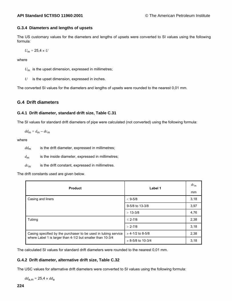
API Standard 5CT/ISO 11960:2001 © The American Petroleum Institute
224
G.3.4 Diameters and lengths of upsets
The US customary values for the diameters and lengths of upsets were converted to SI values using the followingformula:
Um = 25,4 ´ÊU
where
Um is the upset dimension, expressed in millimetres;
U is the upset dimension, expressed in inches.
The converted SI values for the diameters and lengths of upsets were rounded to the nearest 0,01Êmm.
G.4 Drift diameters
G.4.1 Drift diameter, standard drift size, Table C.31
The SI values for standard drift diameters of pipe were calculated (not converted) using the following formula:
ddm = dm Ð dcm
where
ddm is the drift diameter, expressed in millimetres;
dm is the inside diameter, expressed in millimetres;
dcm is the drift constant, expressed in millimetres.
The drift constants used are given below.
dcmProduct Label 1
mm
Casing and liners < 9-5/8 3,18
9-5/8 to 13-3/8 3,97
> 13-3/8 4,76
Tubing ² 2-7/8 2,38
> 2-7/8 3,18
> 4-1/2 to 8-5/8 2,38Casing specified by the purchaser to be used in tubing servicewhere Label 1 is larger than 4-1/2 but smaller than 10-3/4
>Ê8-5/8 to 10-3/4 3,18
The calculated SI values for standard drift diameters were rounded to the nearest 0,01Êmm.
G.4.2 Drift diameter, alternative drift size, Table C.32
The USC values for alternative drift diameters were converted to SI values using the following formula:
dda,m = 25,4 ´Êdda

© The American Petroleum Institute API Standard 5CT/ISO 11960:2001
225
where
dda,m is the alternative drift diameter, expressed in millimetres;
dda is the alternative drift diameter, expressed in inches.
The converted SI values for alternative drift diameters were rounded to the nearest 0,01Êmm.
G.4.3 Drift diameter, finished bored upset of extreme-line casing, column 12 of Table C.26
The US Customary values for the finished bored upset of extreme-line casing were converted to SI values usingthe following formula:
dde,mÊ=Ê25,4Ê´Êdde
where
dde,m is the drift diameter for the finished bored ends of extreme-line casing, expressed in millimetres;
dde is the drift diameter for the finished bored ends of extreme-line casing, expressed in inches.
The converted SI values for the drift diameters for the finished bored ends of extreme-line casing were rounded tothe nearest 0,01 mm.
G.4.4 Drift diameter, for the full length of extreme-line casing, column 13 of Table C.26
Following the custom in USC units, the SI values for the drift diameters for the full length of extreme-line casing areequal to the standard drift diameter for plain-end casing (see G.4.1) except for the following product which use asmaller diameter drift because of the heavy internal upset.
Product which require a smaller full-lengthdiameter drift because of the heavy internal
upset
Product in columns˚1 and 2 are driftedfull length with the standard drift for
the corresponding productin columns˚3 and 4
Label 1 Label 2 Label 1 Label 2
1 2 3 4
5 15.00 5 ³ 18.00
5-1/2 15.50 5-1/2 ³ 20.00
5-1/2 17.00 Ñ Ñ
6-5/8 24.00 6-5/8 ³ 28.00
7 23.00 7 ³ 26.00
7-5/8 26.40 7-5/8 ³ 29.70
8-5/8 32.00 8-5/8 ³ 36.00
9-5/8 40.00 9-5/8 ³ 40.50

API Standard 5CT/ISO 11960:2001 © The American Petroleum Institute
226
G.5 Coupling dimensions
G.5.1 Length of couplings
The USC values for the lengths of couplings in inches and fractions of inches were converted to decimalequivalents in USC units without rounding. The full decimal equivalent of the lengths of the couplings in USC unitswere then converted to SI units using the following formula:
NL,m = 25,4Ê´ÊN
where
NL,m is the length of couplings, expressed in millimetres;
NL is the length of couplings, expressed in inches, without rounding.
The converted SI values for the lengths of couplings were rounded to the nearest 0,01Êmm.
G.5.2 Diameter of coupling recess
The USC values for diameters of the coupling recess were converted to SI values using the following formula:
QmÊ=Ê25,4Ê´ÊQ
where
Qm is the diameter of the coupling recess, expressed in millimetres;
Q is the diameter of the coupling recess, expressed in inches.
The converted SI values for the diameters of the coupling recess were rounded to the nearest 0,01Êmm.
G.5.3 Width of the coupling bearing face
The USC values for the widths of the bearing face of couplings were converted to SI values using the followingformula:
bmÊ=Ê25,4Ê´Êb
where
bm is the width of the coupling bearing face, expressed in millimetres;
b is the width of the coupling bearing face, expressed in inches.
The converted SI values for the width of the coupling bearing faces were rounded to the nearest 0,01Êmm.
G.5.4 Diameter at the root of the coupling thread at the end of the pipe in the power-tight position
The USC values for the diameter at the root of the coupling thread at the end of the pipe in the power-tight positionwere calculated without rounding and were then converted to SI values using the following formula:
d1mÊ=Ê25,4Ê´Êd1
where

© The American Petroleum Institute API Standard 5CT/ISO 11960:2001
227
d1m is the diameter, expressed in millimetres, at the root of the coupling thread at the end of the pipe in thepower-tight position;
d1 is the unrounded diameter, expressed in inches, at the root of the coupling thread at the end of the pipe inthe power-tight position.
The converted SI values for the diameter at the root of the coupling thread at the end of the pipe in the power-tightposition were rounded to the nearest 0,01Êmm.
G.6 Linear mass
G.6.1 Nominal threaded and coupled linear mass
The USC values for nominal threaded and coupled linear mass were converted to SI units using the followingformula:
WmÊ=Ê1,488 16 ´Êw
where
Wm is the linear mass, expressed in kilograms per metre;
w is the linear mass, expressed in pounds per foot.
The converted SI values for nominal threaded and coupled linear mass were rounded to the nearest 0,01Êkg.
G.6.2 Plain-end linear mass
The plain-end linear masses expressed in SI units were calculated (not converted) using the following formula:
Wm,plÊ=Ê0,024 6615 ´Ê(Dm Ð tm) ´Êtm
where
Wm,pl is the plain-end linear mass, expressed in kilograms per metre;
Dm is the outside diameter, expressed in millimetres;
tm is the wall thickness, expressed in millimetres.
The calculated SI values for plain-end linear masses were rounded to the nearest 0,01Êkg/m.
G.6.3 Coupling masses
The USC values for the calculated masses of couplings were converted to SI values using the following formula:
wmÊ=Ê0,453 592 ´Êw
where
wm is the mass of the coupling, expressed in kilograms;
w is the mass of the coupling, expressed in pounds.

API Standard 5CT/ISO 11960:2001 © The American Petroleum Institute
228
The converted SI values for calculated masses of couplings were rounded to the nearest 0,01Êkg.
G.6.4 Mass gain or loss due to end finish
The USC values for mass gain or loss due to end finish were converted to SI units using the following formula:
Dwm,eÊ=Ê0,453Ê592Ê´ÊDwe
where
Dwm,e is the mass gain or loss due to end finish, expressed in kilograms;
Dwe is the mass gain or loss due to end finish, expressed in pounds.
The converted SI values for mass gain or loss due to end finish were rounded to the nearest 0,01 kg.
G.7 Tensile and flattening tests
G.7.1 Yield strength
The USC values for yield strength were converted to SI values using the following formula:
YSm =Ê0,006 894 76 ´ÊYS
where
YSm is the yield strength, expressed in megapascals;
YS is the yield strength, expressed in pounds per square inch.
The converted SI values for strengths were rounded to the nearest megapascal.
G.7.2 Tensile strength
The USC values for tensile strength were converted to SI values using the following formula:
TSm =Ê0,006 894 76 ´ÊTS
where
TSm is the tensile strength, expressed in megapascals;
TS is the tensile strength, expressed in pounds per square inch.
The converted SI values for strengths were rounded to the nearest megapascal.
G.7.3 Elongation
The values for elongation, in SI units, were calculated (not converted) using the following formula:
em =Ê1 944,00 ´ÊAm 0,2/Um0,9

© The American Petroleum Institute API Standard 5CT/ISO 11960:2001
229
where
em is the minimum elongation, expressed as a percentage;
Am is the cross-sectional area of the tensile specimen, expressed in square millimetres;
Um is the specified tensile strength, expressed in megapascals.
The calculated SI values for elongation were rounded to the nearest 1,0Ê% for values of 10,0Ê% and larger and tothe nearest 0,5Ê% for values less than 10,0Ê%.
G.7.4 Flattening test formula
The formula used to determine the maximum distance between the plates during a flattening test had the followingform:
Df =ÊD ´Ê[Z1 Ð (Z2 ´ D /t)]
where
Df is the maximum distance between the plates during a flattening test, expressed in inches or millimetresdepending on the units of D and t;
Z1 is a constant;
Z2 is a constant;
D is the specified outside diameter of the pipe, expressed in inches or millimetres;
t is the specified wall thickness of the pipe, expressed in inches or millimetres.
The same values for the constants Z1 and Z2 were used regardless of whether the units for D and t were inches ormillimetres, provided the units for both D and t were the same.
G.8 Charpy impact energy requirements
G.8.1 Critical thickness for couplings with ISO/API threads, Table C.8
The USC values for the critical thickness for couplings with ISO/API threads were converted to SI values using thefollowing formula:
tc,mÊ=Ê25,4Ê´Êtc
where
tc,m is the critical thickness, expressed in millimetres;
tc is the critical thickness, expressed in inches.
The calculated SI values were rounded to the nearest 0,01 mm.

API Standard 5CT/ISO 11960:2001 © The American Petroleum Institute
230
G.8.2 Charpy impact energy
The standard USC values for impact energy requirements that are not determined by an equation (for example, asused in Table C.11 and other minimum requirements) were converted to SI values using the following formula:
CmÊ=Ê1,355 82Ê´ÊC
where
Cm is the standard Charpy impact energy, expressed in joules;
C is the standard Charpy impact energy, expressed in foot-pounds (e.g. 8, 15, 20, 30 ft-lb).
The converted standard SI values for energy were rounded to the nearest joule.
G.8.3 Minimum absorbed energy requirements for couplings, Tables C.12 to C.18
The SI values for the minimum absorbed energy requirements for ISO/API couplings were calculated using thefollowing formulae:
For Grades N80 Type 1, N80Q, L80, C90, C95, T95, P110 and Q125
Transverse Charpy absorbed energy requirements for couplings:
CctmÊ=ÊfcÊ´ÊYSmaxÊ´Ê [(0,001 18Ê´Êtc)Ê+Ê0,012Ê59]
Longitudinal Charpy absorbed energy requirements for couplings
CclmÊ=ÊfcÊ´ÊYSmaxÊ´Ê [(0,002 36Ê´Êtc)Ê+Ê0,025 18]
where
Cctm is the minimum transverse Charpy impact energy for couplings, expressed in joules;
Cclm is the minimum longitudinal Charpy impact energy for couplings, expressed in joules;
YSmax is the maximum specified yield strength of the coupling, expressed in megapascals;
tc is the critical thickness shown in Table C.8 for ISO/API couplings, expressed in millimetres;
fc is a factor depending on the size of the Charpy impact specimen:
1,00 for full-size specimens (10ÊmmÊ´Ê10Êmm);
0,80 for 3/4-size specimens (10ÊmmÊ´Ê7,5Êmm);
0,55 for 1/2-size specimens (10ÊmmÊ´Ê5Êmm).
The calculated SI values were rounded to the nearest joule.
NOTE 1 The maximum-size fully machined transverse and longitudinal Charpy impact specimens for ISO/API couplings canbe found in API Bul 5C3. These sizes are included in TablesÊC.12 to C.16 and used in the calculation of the Charpyrequirements shown in those tables.
NOTE 2 The absorbed energy requirements in Tables C.17 and C.18 are for full-size test specimens where the factor f is setto 1,00.

© The American Petroleum Institute API Standard 5CT/ISO 11960:2001
231
G.8.4 Absorbed energy requirements for pipe
The SI values for the maximum specified wall thickness for various grades of pipe for minimum absorbed energyvalues from full-size test specimens were calculated based on the equations given in a) and b) below. In theseequations the following is applicable:
Cpt,m is the minimum transverse Charpy impact energy for pipe, expressed in joules;
Cpl,m is the minimum longitudinal Charpy impact energy for pipe, expressed in joules;
YSmax is the maximum specified yield strength of the pipe, expressed in megapascals;
YSmin is the minimum specified yield strength of the pipe, expressed in megapascals.
The rounding procedures of ISO 31-0 or ASTM E29 shall be followed. For example, when calculating therequirements for 27 J, 27,499 999 99 should be used for Cpt,m or Cpl,m (since that rounds to 27). Similarly, whencalculating the requirements for 28 J, 28,500 000 00 should be used for Cpt,m or Cpl,m (since that rounds to 28).The wall thickness that results from the calculation shall be rounded down to two decimal places.
a) Grades N80Q, L-80, C90, C95, T95 and P110
Transverse Charpy absorbed energy requirements for pipe, TableÊC.19:
t = [(Cpt,m/YSmin) — 0,012Ê59] / 0,001Ê18
Longitudinal Charpy absorbed energy requirements for pipe, Table C.20:
t = [(Cpl,m/YSmin) — 0,025Ê18] / 0,002Ê36
b) Grade Q125
Transverse Charpy absorbed energy requirements for pipe, Table C.19:
t = [(Cpt,m/YSmax) — 0,012Ê59] / 0,001Ê18
Longitudinal Charpy absorbed energy requirements for pipe, Table C.20:
t = [(Cpl,m/YSmax) — 0,025Ê18] / 0,002Ê36
G.8.5 Calculated wall thickness required to machine transverse and longitudinal Charpy impactspecimens from pipe and couplings, Tables C.21 and C.22
The calculated wall thickness required to machine transverse and longitudinal Charpy impact test specimens frompipe and couplings were calculated using the following formulae:
Transverse Charpy impact specimens, Table C.21:
tt = (Dm/2) Ð [(Dm/2)2 Ð 756,25]0,5 + 1,00 + wCs
Longitudinal Charpy impact specimens, Table C.22:
tl = (Dm/2) Ð [(Dm/2)2 Ð 25]0,5 + 1,00 + wCs
where
tt is the calculated value for the wall thickness, expressed in millimetres, required to machine transverseCharpy impact test specimens from pipe and couplings;

API Standard 5CT/ISO 11960:2001 © The American Petroleum Institute
232
tl is the calculated values for the wall thickness, expressed in millimetres, required to machine longitudinalCharpy impact test specimens from pipe and couplings;
Dm is the specified outside diameter of the pipe or coupling, expressed in millimetres;
wCs is the width of the Charpy impact test specimen, expressed in millimetres:
10,0Êmm for full-size specimens;
7,5Êmm for 3/4-size specimens;
5,0Êmm for 1/2-size specimens.
In the above formulae a machining allowance of 1,00 mm is included (USC formulae allowed 0,020 in on the insidepipe surface and 0,020 in on the outside surface or 1,00 mm total for the purposes of this calculation).
The calculated SI values for the wall thickness required to machine transverse and longitudinal Charpy impact testspecimens from pipe and couplings were rounded to the nearest 0,01 mm.
G.9 Hydrostatic testing
G.9.1 Hydrostatic test pressure for plain end pipe
The SI values for hydrostatic test pressures for plain end pipe were calculated (not converted) using the SI outsidediameter, wall thickness and yield strengths in the following formula:
pmÊ=Ê2Ê´ÊfÊ´ÊYSmÊ´Êtm/Dm
where
pm is the hydrostatic test pressure, expressed in megapascals;
Dm is the outside diameter, expressed in millimetres;
YSm is the yield strength, expressed in megapascals;
tm is the wall thickness, expressed in millimetres;
f is a factor, based on the size and grade of the pipe as found in the following:
Standard test Alternative testGrades Label 1
f
Maximumpressure
MPa
f
Maximumpressure
MPa
< 10-3/4 0,8 69,0 Ñ ÑH40, J55, K55
³ 10-3/4 0,6 69,0 0,8 69,0
M65, N80, L80, C95, T95 all sizes 0,8 69,0 Ñ Ñ
P110, Q125 all sizes 0,8 69,0 0,8 no max.
The calculated SI values for hydrostatic test pressures for plain-end pipe were rounded to the nearest 0,5 MPa upto a maximum of 69,0 MPa.

© The American Petroleum Institute API Standard 5CT/ISO 11960:2001
233
G.9.2 Hydrostatic test pressure for couplings
The SI values for the maximum hydrostatic test pressures for couplings were calculated (not converted) using thefollowing formula from API Bul 5C3:
pmÊ=Ê0,8Ê´ÊYSmÊ´Ê(WmÐ d1m)/Wm
where
pm is the hydrostatic test pressure, expressed in megapascals;
Wm is the outside diameter of the coupling, expressed in millimetres;
YSm is the yield strength, expressed in megapascals;
d1m is the diameter, expressed in millimetres, at the root of the coupling thread at the plane of the end of thepipe in the power-tight position.
The calculated SI values for the maximum hydrostatic test pressures for couplings were rounded to the nearest0,5ÊMPa up to a maximum of 69,0ÊMPa.
G.9.3 Internal pressure leak-resistance at E1 or E7 plane
The SI values for internal pressure leak-resistance at the E1 plane of round thread connections and at the E7 planeof buttress thread casing were calculated (not converted) using the following formula from API Bul 5C3:
pLRmÊ=ÊEÊ´ÊTÊ´ÊNÊ´ÊPÊ´Ê[Wm2Ê-ÊEs2] / [2Ê´ÊEsÊ´ÊWm2]
where
pLRm is the internal pressure leak-resistance at the E1 or E7 plane, expressed in megapascals;
Wm is the outside diameter of the coupling, expressed in millimetres;
YSm is the yield strength, expressed in megapascals;
d1m is the diameter, expressed in millimetres, at the root of the coupling thread at the plane of the end of the pipe in the power-tight position;
E is the modulus of elasticity, 207 000 MPa;
Es is the pitch diameter at the seal, expressed in millimetres:
E1 for round threads;
E7 for buttress threads;
N is the number of power turns;
P is the thread pitch, expressed in inches per thread;
T is the thread taper, expressed in inches per inch.
The calculated SI values for internal pressure leak-resistance limits were rounded to the nearest 0,5 MPa up to amaximum of 69,0 MPa.

API Standard 5CT/ISO 11960:2001 © The American Petroleum Institute
234
G.9.4 Hydrostatic test pressure for threaded and coupled pipe
The hydrostatic test pressure for threaded and coupled pipe is the lowest pressure of:
the hydrostatic test pressure for plain-end pipe,
the maximum hydrostatic test pressure for couplings, or
the internal pressure leak-resistance.
G.10 Other
G.10.1 Temperature
The temperatures in degrees Fahrenheit (USC) were converted to temperatures in degrees Celsius (SI) using thefollowing formula:
°CÊ=Ê(°FÊÐÊ32)Ê´Ê5/9
where
°C is the temperature, expressed in degrees Celsius;
°F is the temperature, expressed in degrees Fahrenheit.
The converted SI values for temperatures were rounded to the nearest degree.
When the temperature being converted was over 600Ê°F, the number was rounded to the most rational valuerounded to the nearest 5Ê°C. For example, 750Ê°F converts to 399Ê°C but the rational conversion is 400Ê°C.
G.10.2 Torque
NOTE This International Standard does not include requirements for torque. However, as this International Standard is theprimary casing and tubing standard, a conversion procedure for torque is included here for convenience of the user.
The USC values for make-up torque may be converted to SI values using the following formula:
TmÊ=Ê1,355 82Ê´ÊT
where
Tm is the torque, expressed in newton metres;
T is the torque, expressed in foot-pounds.
The converted SI values for make-up torque may be rounded to the nearest newton metre.

© The American Petroleum Institute API Standard 5CT/ISO 11960:2001
235
Bibliography
[1] Failure Analysis and Prevention, ASM Metals Handbook, Volume 11, 9th edn., 1986
[2] J.M.ÊHODGE and M.A.ÊOREHOSKI, Relationship between hardenability and percentage martensite in somelow alloy steels. Trans. AIME, 167, 1946, pp.Ê627-642

02/02

Additional copies are available through Global EngineeringDocuments at (800) 854-7179 or (303) 397-7956
Information about API Publications, Programs and Services isavailable on the World Wide Web at: http://www.api.org
Product No. G05CT7