specifications volume 2 - ebidboard.com · c. asme sec ix - asme boiler and pressure vessel code -...
TRANSCRIPT

SPECIFICATIONSVolume 2
County of Madera
Jail HVAC Replacement
100% Construction Documents
NOVEMBER 10, 2017
Kitchell CEM2450 Venture Oaks Drive, Suite 500
Sacramento, California 95833

THIS PAGE LEFT BLANK

Madera County Jail HVAC Replacement
100% Construction Documents November 10, 201700 01 10 Page 1 of 4
TABLE OF CONTENTS - SECTION 00 01 10
VOLUME 1
DIVISION 0 – BIDDING AND CONTRACT REQUIREMENTS00 01 00 Cover Page00 01 05 Certifications00 01 10 Table of Contents00 11 13 Advertisement for Bids00 21 13 Instructions to Bidders00 21 13.1 Contractor RFC Form00 41 13 Bid Form00 43 36 Proposed Subcontractors Form00 45 13 Bidder’s Qualifications00 45 19 Noncollusion Affidavit00 45 26 Contractor’s Certificate Regarding Workers’ Compensation00 52 13 Contract00 61 00 Bid Bond00 61 13.13 Performance Bond00 61 13.16 Payment Bond for Public Works00 72 13 General Conditions00 73 00 Supplementary Conditions
DIVISION 1 – GENERAL REQUIREMENTS01 04 20 Coordination Drawings01 11 00 Summary of Work01 25 00 Substitutions01 26 00 Contract Modification Procedures01 26 13 Request for Information01 29 00 Payment Procedures01 29 00.1 Lien Release01 31 13 Project Coordination01 31 19 Project Meetings01 32 00 Construction Progress Documentation01 33 00 Submittals01 35 13.16 Project Security Procedures01 35 13.18 Facility Access Application Packet 201701 36 00 Electronic Drawing Files01 41 00 Quality Requirements01 43 39 Mock-ups01 45 23 Testing and Inspection Services01 50 00 Temporary Facilities and Controls01 55 00 Traffic Regulation01 61 00 Product Requirements01 65 00 System Starting01 71 23 Field Engineering01 73 29 Cutting and Patching01 74 00 Cleaning During Construction and Final Cleaning01 77 19 Project Closeout
Madera County Jail HVAC Replacement
100% Construction Documents November 10, 201700 01 10 Page 2 of 4
01 78 36 Warranties and Bonds01 78 36.1 GC Warranty Form01 78 36.2 Sub Warranty Form
DIVISION 2 – SITE CONSTRUCTION02 41 00 Selective Demolition
DIVISION 3 – CONCRETE03 10 00 Concrete Forming and Accessories03 15 00 Concrete Accessories03 20 00 Concrete Reinforcing03 30 00 Cast-In-Place Concrete03 60 00 Grouting
DIVISION 4 – MASONRY 04 05 13 Masonry Mortaring04 05 16 Masonry Grouting04 22 00 Concrete Masonry Unit
DIVISION 5 – METALS05 00 55 Tamper Proof Metal Fastenings05 12 00 Structural Steel Framing05 50 00 Metal Fabrications05 58 00 Formed Metal Fabrication
DIVISION 6 - WOOD AND PLASTICS 06 10 00 Rough Carpentry06 16 00 Sheathing
DIVISION 7 - THERMAL AND MOISTURE PROTECTION07 41 13 Metal Roof Panels07 42 13 Metal Wall Panels07 52 13 Atactic-Polypropylene (APP) Modified Bituminous Membrane Roofing 07 62 00 Sheet Metal Flashing and Trim07 84 13 Penetration Firestopping07 92 00 Joint Sealants
DIVISION 8 - DOORS AND WINDOWS 08 31 10 Access Doors and Frames08 34 60 Detention Doors and Frames08 71 63 Detention Door Hardware
DIVISION 9 - FINISHES09 22 16 Non-Structural Metal Framing09 29 00 Gypsum Board09 51 23 Acoustical Tile Ceilings09 91 13 Exterior Painting09 91 23 Interior Painting

Madera County Jail HVAC Replacement
100% Construction Documents November 10, 201700 01 10 Page 3 of 4
DIVISION 10 – SPECIALTIESNot used
DIVISION 12 – FURNISHINGSNot used
VOLUME 2
DIVISION 22 – PLUMBING22 05 00 Common Work Results for Plumbing22 05 13 Common Motor Requirements for Plumbing Equipment22 05 16 Expansion Fittings and Loops for Plumbing22 05 19 Meters and Gauges for Plumbing Piping22 05 23 General-Duty Valves for Plumbing Piping22 05 29 Hangers and Support for Plumbing22 05 48 Vibration and Seismic Controls for Plumbing22 05 53 Identification for Plumbing22 07 19 Plumbing Piping Insulation22 11 13 Facility Water Distribution Piping22 11 16 Domestic Water Piping22 11 19 Domestic Water Piping Specialties22 35 00 Domestic Water Heat Exchangers
DIVISION 23 – HEATING, VENTILATION AND AIR-CONDITIONING23 05 00 Common Work Results for HVAC23 05 13 Common Motor Requirements for HVAC23 05 16 Expansion Fittings and Loops for HVAC23 05 19 Meters and Gauges for HVAC Piping23 05 23 General-Duty Valves for HVAC Piping23 05 29 Hangers and Supports for HVAC23 05 48 Vibration and Seismic Controls for HVAC23 05 53 Identification for HVAC23 05 93 Testing, Adjusting, and Balancing23 07 00 HVAC Insulation23 09 13 Instrumentation23 09 24 Direct Digital Control System23 11 23 Facility Natural-Gas Piping23 21 13 Hydronic Piping23 21 23 Hydronic Pumps23 31 00 HVAC Ducts and Casings23 33 00 Air Duct Accessories23 34 00 HVAC Fans23 36 00 Air Terminal Units23 51 00 Breechings, Chimneys, and Stacks23 52 16 Condensing Boilers23 64 16 Centrifugal Water Chillers23 65 00 Cooling Towers23 73 23 Custom Indoor Air Handling Units

Madera County Jail HVAC Replacement
100% Construction Documents November 10, 201700 01 10 Page 4 of 4
DIVISION 26 – ELECTRICAL26 00 50 Basic Electrical Materials and Methods26 01 00 General conditions for Electrical Work26 05 19 Low-Voltage Electrical Power Conductors and Cables26 05 26 Grounding and Bonding for Electrical Systems26 05 29 Hangers and Supports for Electrical26 05 48 Vibration and Seismic Controls26 24 19 Motor Control Centers26 95 00 Electrical Acceptance Tests
DIVISION 32 – EXTERIOR IMPROVEMENTS32 31 13.53 High Security Chain Link Fences and Gates
END OF SECTION 00 01 10

Madera County Jail HVAC Replacement
100% Construction Documents November 10, 201722 05 00 Page 1 of 16
SECTION 22 05 00 - COMMON WORK RESULTS FOR PLUMBING
PART 1 GENERAL
1.1 SUMMARY
A. Section Includes:1. Pipe, tube, and fittings.2. Miscellaneous piping materials/products.3. Valves.4. Piping specialties.5. Pipe escutcheons.6. Mechanical sleeve seals.7. Fire barrier penetration seals.8. Fabricated piping specialties.9. Motors and drives.
1.2 REFERENCES
A. American Society of Mechanical Engineers (ASME).1. ASME B31.1 - Power Piping.2. ASME B31.9 - Building Services Piping.3. ASME B16.20 - Metallic Gaskets for Pipe Flanges; Ring-Joint, Spiral-Would, and
Jacketed4. ASME B16.21 - Nonmetallic Flat Gaskets for Pipe Flanges.5. ASME B16.10 - Face-to-Face and End-to-End Dimensions of Valves.6. ASME B16.34 - Valves Flanged, Threaded and Welding End.
B. National Certified Pipe Welding Bureau (NCPWB) - Standard Procedure Specifications.
C. ASME SEC IX - ASME Boiler and Pressure Vessel Code - Section IX: Welding and Brazing Qualifications.
D. ANSI Standards.1. ANSI B16.20.1- Metallic Gaskets for Pipe Flanges - Ring Joint, Spiral-Wound, and
Jacketed.
E. AWWA Standards1. AWWA C111- Rubber - Gasket Joints for Ductile - Iron Pressure Pipe and Fittings.
F. MSS Compliance:1. MSS SP-25 - Marking System for Valves, Fittings, Flanges and Unions.2. MSS SP-72 - Ball Valves with Flanged or Butt-Welding Ends for General Service.3. MSS SP-80 - Bronze Gate, Globe, Angle and Check Valves.4. MSS SP-67 - Butterfly Valves.5. MSS SP-70 - Gray Iron Gate Valves, Flanged and Threaded Ends.6. MSS SP-85 - Gray Iron Globe and Angle Valves, Flanged and Threaded Ends.7. MSS SP-78 - Gray Iron Plug Valves, Flanged and Threaded Ends.8. MSS SP-71 - Gray Iron Swing Check Valves, Flanged and Threaded Ends.

Madera County Jail HVAC Replacement
100% Construction Documents November 10, 201722 05 00 Page 2 of 16
G. FCI Compliance:1. FCI 73-1 - Pressure Rating Standard for “Y” Type Strainers.2. FCI 78-1- Pressure Rating Standard for Pipeline Strainers Other than “Y Type.
1.3 DEFINITIONS
A. “Piping” includes, in addition to pipe, all fittings, flanges, valves, hangers and other accessories related to such piping.
B. “Wiring” includes in addition to conductors, all raceway, conduit, fittings, boxes, switches, hangers and other accessories related to such wiring.
C. “Concealed” means hidden from sight in chases, furred spaces, shafts, hung ceilings or embedded in construction.
D. “Exposed” means not installed underground or “concealed” as defined above.
E. “Provide” means to furnish and install.
1.4 SUBMITTALS
A. General1. Comply with the requirements of Division 1 and the specific requirements of the
Sections of Division 22.2. Submit all similar equipment together as part of the same submittal. For example:
a. All water heaters must be contained in the same submittal.b. All pumps must be contained in the same submittal.
3. Contractor must review all submittals prepared by each supplier and mark all copies as acceptable to the Contractor. This acceptance must signify that all required service connections are shown and in the proper location to meet the installation requirements and that the equipment can fit in the space allowed.
4. Do not order equipment until submittals have been reviewed and approved by the Owner Representative.
5. Each item submitted must be labeled or identified the same as on the drawings.6. Mark submittal “Exactly as Specified” or accompanied by a letter from the supplier
explaining in detail what difference, if any, exists between the submitted item and the specified item. Failure to point out the differences will be considered cause for disapproval. The Owner Representative will not assume any responsibility for differences concealed or otherwise not brought to their attention, and the Contractor will be required to correct any deficiencies or differences discovered at a later date, and assume responsibility for any delays, damage, and/or expenses incurred by others due to such action.
7. Brands or trade names are mentioned to set standards of quality only; use no substitute materials, however, unless approved in writing by the Owner Representative. Approval of substitute materials does not relieve the Contractor of responsibility for providing a workable and functioning system as specified.
8. Submittals will be checked for general conformance with the design concept but acceptance by the Owner Representative in no manner is meant to verify that dimensions, quantities, or location of services are as necessary to meet the job requirements. This remains the responsibility of the Contractor.
Madera County Jail HVAC Replacement
100% Construction Documents November 10, 201722 05 00 Page 3 of 16
B. Shop Drawings1. General: Prepare and submit plans, sections, details and diagrams to required scales for
specified areas. Drawings must be coordinated, dimensioned, indicate equipment and piping in relation to architectural and structural features as well as other building systems. Include minor piping, drains, air vents, etc. Indicate exact locations and elevations of valves, piping specialties, access doors, etc.
2. Required Drawings: Prepare and submit drawings for all areas and all plumbing work. Scale must be minimum 3/8” = 1’-0” in mechanical rooms, fan rooms, and mechanical areas, and minimum 1/4” = 1’-0” elsewhere.
C. Coordination Drawings1. General: Coordination drawings are defined as “shop drawings” which also indicate, on
the same drawings, the major utilities of all other trades. “Coordination drawings” must indicate location and elevations of structural slabs and beams, architectural elements, domestic water piping, plumbing vents, sanitary drains, storm drains, fire protection piping, lighting fixtures, electrical conduits (2-inch and larger), ductwork, penetrations of walls and roof, fire dampers, fire/smoke dampers, automatic dampers, terminal boxes, air outlets, access panels, ceiling mounted equipment and controls, gas piping, flues, fans, air handling equipment, etc.
2. Submit coordination drawings for the following:a. Entire housing buildings and Central Plant.b. Other areas for which space is limited.
3. It is the intent of the coordination drawings to ensure coordination of all major utilities, prior to the start of installation. This is a substantial effort which will require careful and detailed coordination and planning to ensure appropriate information is available, from all trades, in a timely manner. The coordination drawing effort must be integrated into the project schedule and monitored to ensure conformance.
4. Conflicts between trades, which cannot be resolved through generally accepted practice of coordination between trades, must be clouded on the coordination drawings and an appropriate description of the problem noted for review by the Owner Representative.
5. Nonconforming M/E work installed within designated coordination areas is subject to removal and replacement by installing contractor at no additional cost to Owner.
6. Coordination drawings must be signed and dated by individual trade constructors. By act of signature and submittal of singular combined coordination drawings, each trade contractor acknowledges coordination of their portion of the Work with all other plumbing, mechanical, electrical, architectural, and structural work contractors.
D. Product Data1. General: Manufacturer’s specifications, data sheets, certified drawings, and installation
instructions. Include physical and performance data such as weights, sizes, capacities, required clearances, performance curves, acoustical characteristics, finishes, color selection, location and size of field connections, and accessories. Include certified drawings on major equipment such as boilers, water chillers, cooling towers, controls, pumps, and tanks.
2. Motors: Submit manufacturer’s name, type, RPM, HP (KW), full load amps, efficiency, and power factor.
3. Part Load Performance: Submit equipment data to indicate performance characteristics throughout ranges of possible load conditions.

Madera County Jail HVAC Replacement
100% Construction Documents November 10, 201722 05 00 Page 4 of 16
4. Include operating weight and location of center of gravity of each item of equipment in manufacturer’s cut sheet for purposes of seismic calculation.
5. Pipes and Pipe Fittings: Submit schedule showing pipe material data, sizes, fitting valve type k factor, working pressure for each service.
6. Submit valve schedule showing manufacturer’s figure number, size, location, and valve features for each required valve.
7. Submit schedule showing manufacturer’s figure number, size, location, and features for each required piping specialty.a. Strainers: include pressure drop or chart for each type and size.b. Meters and gauges: include scale range for each service.
E. Test Reports1. Manufacturer’s Tests
a. Factory Tests: As specified for specific equipment.b. Field Tests: As specified.
2. System Pressure Tests: As specified under “Testing” article. Test log of pressure tests on each system. Indicate date of test, scope of test, test pressure, duration, and observers.
F. Certification1. Seismic Restraints: As specified under Section 22 05 29 and 22 05 48.2. Welding Certificates.3. Brazing Certificates.
G. Operating and Maintenance Manuals: Include, but not limited to, the following:1. List of all equipment with Manufacturer’s name, model number, and local
representative, service facilities and normal channel of supply for each item. Include phone number and address of service facilities
2. System Description: Description of start-up, operating, and shutdown procedures.3. Controls: Diagrams and description of operation sequence of each system.4. Equipment: Manufacturer’s brochures, ratings, certified shop drawings, lubrication
charts and data, parts lists with part numbers, and belt and sheave data. Mark each sheet with equipment identification number and actual installed condition.
5. Materials and Accessories: Manufacturer’s brochures parts lists with part numbers and lubrication data where applicable. Mark each sheet with equipment identification number or system and location of installation; and to specifically identify which options are provided (in case where data sheet shows multiple options).
6. Certificate of factory tests, field tests and code compliance as specified.7. Wiring and controls schematics.8. Trouble shooting directions.9. Maintenance procedures and frequencies.10. Description of special tools.11. Copies of warranties.12. Safety precautions.13. Emergency contingencies.
H. Record Documents1. Comply with the Conditions of the Contract and the requirements of Section 22 05 53.2. Indicate mains and branches of piping systems, with valves and control devices located
and numbered per valve schedule, concealed unions located, and with items requiring

Madera County Jail HVAC Replacement
100% Construction Documents November 10, 201722 05 00 Page 5 of 16
maintenance located (i.e. traps, strainers, expansion compensators, vents, etc.). Indicate actual inverts and horizontal locations of underground piping.
3. Indicate equipment locations (exposed and concealed), dimensioned from prominent building lines.
4. Identify approved substitutions, Contract Modifications, and actual equipment and materials installed.
I. Samples: When specified under applicable Sections.
1.5 QUALITY ASSURANCE
A. Perform all work in accordance with following rules (codes, standards and regulations): 1. Codes
a. California Building Code, Latest Edition: CBCb. California Fire Code, Latest Edition: CFCc. California Electrical Code, Latest Edition: CECd. California Plumbing Code, Latest Edition: CPCe. California Mechanical Code, Latest Edition: CMCf. California Occupational Safety Health Act: OSHAg. California Code of Regulations: CCRh. CCR Title 24 California Energy Code: CECi. Applicable Local Codes and Ordinances.
2. Standardsa. Air Conditioning and Refrigeration Institute: ARIb. Air Movement and Control Association, Inc.: AMCAc. American National Standards Institute: ANSId. American Society of Heating, Refrigeration, and Air Conditioning Engineers:
ASHRAEe. American Society of Mechanical Engineers: ASMEf. American Society of Plumbing Engineers: ASPEg. American Society of Testing and Materials: ASTMh. American Water Works Association: AWWAi. American Welding Society: AWSj. Associated Air Balance Council: AABCk. Factory Mutual: FMl. International Association of Plumbing and Mechanical Officials: IAPMOm. Institute of Boiler and Radiator Manufacturers: IBRn. Manufacturer’s Standardization Society of the Valves and Fittings Industry: MSSo. National Electrical Manufacturers Association: NEMAp. National Electrical Testing Association: NETAq. National Environmental Balancing Bureau: NEBBr. National Fire Protection Association: NFPAs. Plumbing and Piping Industry Council: PPICt. Sheet Metal and Air Conditioning Contractors National Association, Inc.:
SMACNAu. Underwriters’ Laboratories: UL
3. Regulationsa. California State Fire Marshal: CSFMb. California State Department of Public Health: CSDPHc. Safety Orders of Division of Industrial Safety: SODIS
Madera County Jail HVAC Replacement
100% Construction Documents November 10, 201722 05 00 Page 6 of 16
d. TIER 1: Energy Standard for State Buildings: TIER 14. Where standards of Contract Documents for materials and/or workmanship are higher
than those of applicable rules, Contract Documents must take precedence; otherwise the rules must govern.
5. Nothing in the Contract Documents is to be interpreted as permitting the Work not conforming to the rules.
6. Should there be any direct conflict between the rules and the Contract Documents, the rules must govern.
7. Charges for all materials and labor required for the compliance with rules and regulations must be included in the Contract Price.
B. Certifications: Provide proof of code compliance for equipment as follows:1. Gas Fired Equipment and Safety Devices: Per applicable standards and bear label of
CGA.a. Fuel-burning heating appliances must bear permanent and legible factory-applied
nameplate on which must appear: manufacturer’s name; approved fuel input rating, expressed in Btu/hr.; model and serial numbers; instructions for lighting, operation, and shutdown; type fuel approved for use; and symbol of approved agency certifying compliance of equipment with recognized standards.
2. Electrical Equipment and Safety Devices: Per applicable standards of NEC; UL listed or classified.
3. Pressure Vessels and Pressure Safety Devices: Per applicable standards and bear label of ASME.
4. Energy Conservation: Comply with applicable codes. Provide equipment and materials certified by manufacturer per California energy code as applicable.
5. Equipment: Provide UL listed or classified equipment where required by code officials. Verify such requirements.
C. Repair or replace, to the satisfaction of the Owner, any damage to Work of this Section and damage caused by Work of this Section.
D. Workmanship must be first class throughout and performed only by competent and experienced workmen in a manner satisfactory to the Owner. Constant supervision of the Work, either by the Contractor or his competent representative, must be maintained.
E. Work must be installed so as not to delay the progress of construction and must be properly coordinated with other trades.
F. Use only new materials in perfect condition. Inspect all materials upon arrival at job site and immediately remove defective items from site.
1.6 DELIVERY, STORAGE, AND HANDLING
A. Provide factory-applied plastic end-caps on each length of pipe and tube. Maintain end-caps through shipping, storage and handling as required to prevent pipe-end damage and eliminate dirt and moisture from inside of pipe and tube.
B. Where possible, store pipe and tube inside and protected from weather. Where necessary to store outside, elevate above grade and enclose with durable, waterproof wrapping.

Madera County Jail HVAC Replacement
100% Construction Documents November 10, 201722 05 00 Page 7 of 16
C. Protect flanges and fittings from moisture and dirt by inside storage and enclosure, or by packaging with durable, waterproof wrapping.
1.7 SUBSTITUTIONS
A. General1. Base manufacturer is indicated in equipment schedules.2. In Specification, additional acceptable manufacturer(s) may be indicated.3. Other manufacturers, materials, or methods must not be used unless approved in writing
by the Owner Representative.4. The burden of proof as to the equality of any proposed substitute manufacturer, material,
or method must be upon the Contractor.5. The Owner Representative’s decision must be final.
B. Requests for substitution review and acceptance must be accomplished by table of comparison listing pertinent features of both specified and proposed materials, such as materials of construction, performance, dimensions, weights, replacement or maintenance access, motor type, horsepower, voltage, phase, service factor. Review of proposed substitutions will not be made until receipt of satisfactory comparison tabulation.
C. Submittal of substitutions must be limited to one proposal for each type or kind of item, unless otherwise permitted by the Owner Representative. If first proposed product submittal is rejected, Contractor must then submit the first-named or scheduled product.
D. Contractor must be responsible for all costs and coordination due to the substitution, such as impacts on electrical requirements, weight, openings in slabs and roofs, structural framing, housekeeping pad size, etc.
1.8 JOB CONDITIONS
A. Cause as little interference or interruption of existing utilities and services as possible. Schedule Work which will cause interference or interruption in advance with Construction Manager.
B. Examine Contract Documents to determine how other Work will affect execution of plumbing Work.
C. Determine and verify locations of all existing utilities.
D. Arrange for, coordinate, and pay costs incidental to providing utility company services indicated.
E. Establish lines and levels for each system and coordinate with other systems to prevent conflicts and maintain proper clearances and accessibility.

Madera County Jail HVAC Replacement
100% Construction Documents November 10, 201722 05 00 Page 8 of 16
PART 2 PRODUCTS
2.1 PIPE, TUBE, AND FITTINGS
A. Refer to individual Division 22 piping sections for pipe, tube, fittings materials joining methods. Comply with governing regulations.
2.2 MISCELLANEOUS PIPING MATERIALS/PRODUCTS
A. Welding Materials: Provide welding materials to comply with installation requirements.1. Comply with Section II, Part C, ASME Boiler and Pressure Vessel Code for welding
materials.
B. Gaskets for Flanged Joints: ASME B16.21; full-faced for cast-iron flanges; raised-face for steel flanges, unless otherwise indicated.
2.3 VALVES
A. General: Refer to Section 22 05 23.
2.4 PIPING SPECIALITIES
A. General: Provide factory-fabricated piping specialties recommended by manufacturer for use in service indicated. Provide piping specialties of types and pressure ratings indicated for each service or, if not indicated, provide proper selection as determined by Installer to comply with installation requirements. Provide sizes as indicated, and connections, which properly mate with pipe, tube, equipment connections. Where more than one type is indicated, selection is Installer’s option.
B. Dielectric Unions and Flanges1. General: Provide standard products recommended by manufacturer for use in service
indicated, which effectively isolate ferrous from non-ferrous piping (electrical conductance), prevent galvanic action, and stop corrosion. Pressure rating equal to or greater than that of nearby valves.
2. Manufacturersa. B & K Industries, Inc.b. Capital Mfg. Co.; Div. of Harsco Corp.c. Eclipse, Inc.d. Epco Sales, Inc.e. Perfection Corp.f. Rockford-Eclipse Div.g. Victaulic/Clearflow.h. Calpico.
C. Thermometers: Refer to Section 22 05 19.
D. Thermometer Wells: Refer to Section 22 05 19.
E. Pressure Gauges: Refer to Section 22 05 19.
F. Pressure Gauge Cocks: Refer to Section 22 05 19.

Madera County Jail HVAC Replacement
100% Construction Documents November 10, 201722 05 00 Page 9 of 16
G. Test Fittings: Refer to Section 22 05 19.
2.5 PIPE ESCUTCHEONS
A. General: Provide solid (not split-hinged) pipe escutcheons as specified herein with inside diameter closely fitting pipe outside diameter, or outside of pipe insulation where pipe is insulated. Select outside diameter of escutcheon to completely cover pipe penetration hole in floors, walls, or ceilings; and pipe sleeve extension, if any. Furnish pipe escutcheons with nickel or chrome finish for occupied areas, prime paint finish for unoccupied areas. All escutcheons must be vandal proof.
B. Pipe Escutcheons for Moist Areas: For waterproof floors, and areas where water and condensation can be expected to accumulate, provide solid brass or solid sheet brass pipe escutcheons.
C. Pipe Escutcheons for Dry Areas: Provide solid sheet metal escutcheons.
D. Manufacturers1. Chicago Specialty.2. Producers Specialty.3. Sanitary-Dash.
2.6 MECHANICAL SLEEVE SEALS
A. General: Modular mechanical type, consisting of interlocking synthetic rubber links shaped to continuously fill annular space between pipe and sleeve, connected with bolts and pressure plates which cause rubber sealing elements to expand when tightened, providing watertight seal and electrical insulation.
B. Sleeve: To be furnished by same manufacturer of seals; schedule 40 galvanized steel pipe or Century line sleeves, with integral anchor and waterstop collar.
C. Manufacturers1. Thunderline Link Seal.2. Metraflex Metraseal.
2.7 FIRE BARRIER PENETRATION SEALS
A. Provide seals for any opening through fire-rated walls, floors, or ceilings used as passage for plumbing components such as piping. 1. Piping: Provide fire stopping material as specified in Section 07 84 13.
2.8 FABRICATED PIPING SPECIALTIES
A. Pipe Sleeves: Provide pipe sleeves of one of the following:1. Sheet-Metal: Fabricate from galvanized sheet metal; round tube closed with snaplock
joint, welded spiral seams, or welded longitudinal joint. Fabricate from the following gauges:a. 3-inch and smaller: 0.040-inch/20 gauge thick.b. 4 to 6-inch: 0.064-inch/16 gauge thick.c. Over 6-inch: 0.079-inch/14 gauge thick.

Madera County Jail HVAC Replacement
100% Construction Documents November 10, 201722 05 00 Page 10 of 16
2. Steel Pipe: See Section “Mechanical Sleeve Seals”.
2.9 MOTORS AND DRIVES
A. Motor controls and power wiring1. Provided as part of Division 26 work, unless indicated otherwise, including motor
control switches, starters, disconnects, conduit and wiring, except for low voltage control wiring required for temperature controls.
2. Where equipment is specified with factory pre-wired controls and is furnished instead with components shipped loose, plumbing contractor must be responsible for coordinating the complete installation and assume any additional costs.
B. Motors1. Ball or roller bearing type, high efficiency type, with starting and running characteristics
consistent with torque and speed requirements of driven machine.2. Use motors rated in accordance with NEMA performance standards to carry full
nameplate load continuously at maximum temperature rise of 72 degrees F above ambient with service factor of 1.15.
3. Motors driven by variable frequency drives must be rated for inverter duty and must meet the requirements of NEMA MG-1 part 31.4.4.2.
4. Where substitute manufacturers are provided with different control panels, starters, or electrical characteristics from scheduled equipment, contractor must coordinate complete installation and assume any additional costs.
5. Do not allow power requirements of driven machine to exceed nominal nameplate rating of motor furnished.
6. Do not include service factor when selecting motor horsepower.7. Motors exposed to moisture or rain must be totally enclosed, fan cooled (TEFC). Others
may be open drip proof (ODP), unless otherwise indicated.
C. Motor electrical power characteristics: 460 V, 3-phase, 60 Hz for 1/2 HP and larger; 115 V, 1-phase, 60 Hz for smaller than 1/2 HP, unless noted otherwise.
D. Efficiency1. Requirements apply to all motors, 1/2 HP and larger.2. Ratings in accordance with IEEE 112b Rating Method.
a. Motors must be labeled as NEMA “Premium” Efficient, with efficiencies as follows, based on 1750 RPM.;
% EfficiencyHP ODP TEFC1/2 80.5 78.53/4 82.5 80.01 85.5 85.5
1-1/2 86.5 86.52 86.5 86.53 89.5 89.55 89.5 89.5
7-1/2 91.0 91.710 91.7 91.715 93.0 92.4

Madera County Jail HVAC Replacement
100% Construction Documents November 10, 201722 05 00 Page 11 of 16
20 93.0 93.025 93.6 93.630 94.1 93.640 94.1 94.150 94.5 94.560 95.0 95.0
3. Motors with other than 1750 RPM must be same type motor as would meet requirements for 1750 RPM motors.
4. Spare Parts: Provide one complete set of spare belts for all equipment items. When two or more pieces of equipment require identical belts, provide quantity of spare belts sufficient to serve two pieces of equipment. a. Obtain receipt from Owner. b. Identify each belt by equipment ID.
PART 3 EXECUTION
3.1 PIPING INSTALLATION
A. General: Install pipes and pipe fittings in accordance with recognized industry practices which will achieve permanently-leakproof piping systems, capable of performing each indicated service without piping failure. Install each run with minimum joints and couplings, but with adequate and accessible unions for disassembly and maintenance/replacement of valves and equipment. Reduce sizes (where indicated) by use of reducing fittings. Align piping accurately at connections, within 1/16-inch misalignment tolerance.
B. Locate piping runs, except as otherwise indicated, vertically and horizontally (pitched to drain) and avoid diagonal runs wherever possible. Orient horizontal runs parallel with walls and column lines. Locate runs as shown or described by diagrams, details and notations or, if not otherwise indicated, run piping in shortest route which does not obstruct usable space or block access for servicing building and its equipment. Hold piping close to walls, overhead construction, columns and other clearance to 1/2-inch where furring is shown for enclosure or concealment of piping, but allow for insulation thickness, if any. Where possible, locate insulated piping for 1-inch clearance outside insulation. Wherever possible in finished and occupied spaces, conceal piping from view, by locating in column enclosures, in hollow wall construction or above suspended ceilings; do not encase horizontal runs in solid partitions, except as indicated.
C. Locate groups of pipes parallel to each other, spaced to permit applying insulation and servicing of valves.
D. Electrical and Elevator Equipment Spaces: Do not run piping through transformer vaults, electrical rooms and other electrical or electronic equipment spaces and enclosures, unless piping or ductwork is for equipment serving that electrical space.
E. Comply with ASME B 31.1.
F. Pressures: Do not install piping, valves or piping specialties where exposed to system pressures greater than their rated working pressures.

Madera County Jail HVAC Replacement
100% Construction Documents November 10, 201722 05 00 Page 12 of 16
G. Sloping, Air Venting and Draining:1. Slope piping as indicated, true to line and grade, and free of traps and air pockets. Unless
indicated otherwise, slope piping in direction of flow as follows:
Service Inclination Min. SlopeCooling Coil Condensate Drain
Down 1/8” per foot(1-percent)
H. Install piping free of sags and bends. Support requirements are specified in Section 22 05 29.
I. Fittings1. Provide standard, manufactured fittings in all cases. Field fabricated fittings are
prohibited. Bushings are prohibited on pressure piping.2. Weld-O-Lets and Thread-O-Lets may be used for non-galvanized steel piping if main
pipe size is at least three standard pipe sizes larger than branch pipe, e.g. 2-inch main and 1-inch branch.
3. Provide insulating couplings at connections of ferrous piping to non-ferrous piping.
3.2 INSTALLATION OF VALVES
A. General: Except as otherwise indicated, comply with the following requirements:1. Install valves where required for proper operation and isolation of equipment, including
valves in branch lines where necessary to isolate sections of piping. Locate valves so as to be accessible and so that separate support can be provided when necessary.
2. Install valves with stems pointed up, in vertical position where possible, but in no case with stems pointed downward from horizontal plane unless unavoidable. Install valve drains with hose-end adapter for each valve that must be installed with stem below horizontal plane.
B. Insulation: Where insulation is indicated, install extended-stem valves, arranged in proper manner to receive insulation.
C. Renewable Seats: Select and install valves with renewable seats, except where otherwise indicated.
D. Fluid Control: Except as otherwise indicated, install gate, ball, globe, and butterfly valves to comply with ASME B31.9. Where throttling is indicated or recognized as principal reason for valve, install globe valves.
E. Installation of Check Valves1. Swing Check Valves: Install in horizontal position with hinge pin horizontally
perpendicular to center line of pipe. Install for proper direction of flow.2. Wafer Check Valves: Install between two flanges in horizontal or vertical position,
position for proper direction of flow. Provide silent type wafer check valves at pump discharge locations.
3. Lift Check Valve: Install in piping line with stem vertically upward, position for proper direction of flow.
F. Install globe valves to close against pressure.

Madera County Jail HVAC Replacement
100% Construction Documents November 10, 201722 05 00 Page 13 of 16
G. Install plug valve with seat toward equipment to be isolated.
H. Valve Discharge Piping: Provide discharge pipe to atmosphere from all relief and safety valves, sized with area equal to sum of outlet areas of all valves connected thereto, unless indicated larger.
3.3 INSTALLATION OF PIPING SPECIALTIES
A. Pipe Escutcheons: Install pipe escutcheons on each pipe penetration thru floors, walls, partitions, and ceilings where penetration is exposed to view; and on exterior of building. Secure escutcheon to pipe or insulation so escutcheon covers penetration hole, and is flush with adjoining surfaces.
B. Dielectric Unions and Flanges: Install at each piping joint between ferrous and non-ferrous piping. Comply with manufacturer’s installation instructions.
C. Mechanical Sleeve Seals: Loosely assemble rubber links around pipe with bolts and pressure plates located under each bolt head and nut. Push into sleeve and center. Tighten bolts until links have expanded to form watertight seal.
D. Fire Barrier Penetration Seals: Fill entire opening with sealing compound. Adhere to manufacturer’s installation instructions.
3.4 INSTALLATION OF FABRICATED PIPING SPECIALTIES
A. Pipe Sleeves: Install pipe sleeves of types indicated where piping passes through walls, floors, ceilings, and roofs.1. Do not install sleeves through structural members, except as detailed on Drawings, or as
reviewed by the Owner Representative. 2. Install sleeves accurately centered on pipe runs.3. Size sleeves so that piping and insulation (if any) will have free movement in sleeve,
including allowance for thermal expansion; but not less than two pipe sizes larger than piping run.
4. Where insulation includes vapor-barrier jacket, provide sleeve with sufficient clearance for installation.
5. Pack 100 percent of annular space between sleeve and pipe or pipe insulation. Provide acoustical sealant at each end of pipe sleeve to seal packing in place.a. At fire-rated walls, partitions, floors, roofs, and ceilings: Packing must be through-
penetration firestop.b. At non-fire-rated walls, partitions, floors, roofs, and ceilings: Packing must be
fiberglass insulation, with density of 1.5 pcf. 6. Install length of sleeve equal to thickness of construction penetrated, and finish flush to
surface; except floor sleeves.7. Extend floor sleeves 1 inch above level floor finish.8. Provide temporary support of sleeves during placement of concrete and other work
around sleeves. 9. Provide temporary closure to prevent concrete and other materials from entering sleeves.
B. Type of Sleeves1. Install sheet-metal sleeves at walls and partitions.
Madera County Jail HVAC Replacement
100% Construction Documents November 10, 201722 05 00 Page 14 of 16
2. Install schedule 40 pipe sleeves in concrete slabs.3. Install mechanical sleeve seals at exterior penetrations; below grade, and at slabs-on-
grade.
C. Mechanical Sleeve Seals: Install in accordance with the manufacture’s instructions.
3.5 PIPING EXPANSION PROVISIONS
A. General: Install domestic hot water piping with at least four elbows or tees at following locations.1. Between piping mains and risers.2. Between equipment and pump or tank.3. Between piping main and equipment.
B. Expansion Loops: Fabricate expansion loops as indicated, and elsewhere as determined by Installer for adequate expansion of installed piping system. Provide pipe anchor and pipe alignment guides as indicated, and elsewhere as determined by Installer to properly anchor piping in relationship to expansion loops.1. At Contractor’s option, pipe anchors may be insulated lugged anchors; Pipe Shields,
Inc.; Model #C4000 Series. Comply with requirements for insulated pipe supports in Section 22 05 29.
2. At Contractor’s option, pipe guides may be guided insulated pipe supports; Pipe Shields, Inc.; Model #B3000 or B7000 Series. Comply with requirements for insulated pipe supports in Section 22 05 29.
3.6 INSTALLATION OF EQUIPMENT AND DEVICES
A. Install all equipment in accord with manufacturer’s recommendations and in accordance with the equipment’s listing (if applicable).
B. Access1. Install all equipment and devices to permit easy access for maintenance.2. Maintain easy access to all equipment and devices installed as part of Division 22 Work,
including but not limited to, motors, drives, valves, actuators, etc.3. Proper access must include:
a. Valves may be operated.b. Control devices may be adjusted.c. Equipment access panels may be opened.d. Normal maintenance work such as lubrication of bearings, etc., may be performed
readily within arm’s reach of access opening.4. Relocate items which interfere with access.5. When possible, install Work in accessible locations to avoid the need for access panels.6. Provide access panels in ceilings, partitions, enclosures, etc. as required in order to
achieve easy access to all equipment and devices provided or installed under Division 22 Work. Many access panel locations may be indicated on the Drawings. Provide additional access panels as required.a. For non-security walls, partitions, ceilings, enclosures, etc.: Provide non-security
access panels as Work of Division 22. Requirements for access doors/panels are specified in Section 08 31 10.

Madera County Jail HVAC Replacement
100% Construction Documents November 10, 201722 05 00 Page 15 of 16
b. For security walls, partitions, ceilings, enclosures, etc.: Provide security access panels as Work of Division 22. Requirements for security access panels are specified in Section 08 31 10.
7. Coordinate with the Owner Representative to achieve acceptable locations of access panels.
8. Coordinate all access panel locations with other trades and the Contractor.9. Where possible, avoid locating access panels in secure areas.10. Provide stainless steel access panels in areas subject to moisture.
C. Provide all necessary anchoring devices and supports. 1. Use structural supports suitable for equipment, or as indicated.2. Check loadings and dimensions of equipment with shop drawings.3. Do not cut or weld to building structural members, unless specifically indicated.4. Provide all required equipment supports, including those not detailed on architectural
and mechanical Drawings.5. Comply with Section 22 05 29 and 22 05 48.
D. Verify that equipment will fit support layouts indicated.1. Where substitute equipment is used, revise indicated supports to fit, at no additional cost
to the Owner.
E. Coordinate size and location of roof penetrations, floor penetrations, and wall openings with Work of other Sections.
F. Install rain hoods and metal counter flashings as indicated and as required to make all penetrations of plumbing work through walls and roofs, water and weather-tight. Furnish all clamps, waterproofing material and labor necessary.
G. Install floor mounted equipment on 6-inch high concrete pad, 6 inches larger on each side than base of unit, unless otherwise specified, indicated, or equipment manufacturer’s recommendation calls for. Coordinate size and location of equipment pads and curbs with Work of other Sections.
H. In Mechanical Rooms, Mechanical Areas, Fan Rooms, etc., coordinate locations of floor drains, floor sinks, etc. with locations of equipment and housekeeping pads. Locate drains to properly serve equipment and to result in orderly routing of drain piping, while minimizing tripping hazards, etc.
I. In areas other than mechanical rooms, do not install piping, or equipment in exposed manner unless indicated otherwise.
3.7 ADJUSTING AND CLEANING OF VALVES
A. Valve Adjustment: After piping systems have been tested and put into service, but before final testing, adjusting, and balancing, inspect each valve for possible leaks. Adjust or replace packing to stop leaks, replace valve if leak persists.
B. Cleaning: Clean factory-finished surfaces. Repair any marred or scratched surfaces with manufacturer’s touch-up paint.
C. Valve Identification: Tag each valve in accordance with Section 22 05 53.

Madera County Jail HVAC Replacement
100% Construction Documents November 10, 201722 05 00 Page 16 of 16
3.8 ADJUSTING AND CLEANING OF PIPING SPECIALTIES
A. Adjusting: Adjust faces of meters and gauges to proper angle for best visibility.
B. Cleaning: Clean windows of meters and gauges and factory-finished surfaces. Replace cracked or broken windows; repair any scratched or marred surfaces with manufacturer’s touch-up paint.
3.9 EQUIPMENT VIBRATION
A. Mechanical Balance: Pumps, motors, and drives, when equipment is installed and in normal operation, must be within the following maximum limits, unless specified more restrictively for individual equipment items:1. 600 RPM and Less: 0.003-inch displacement, peak-to-peak.2. Over 600 RPM: 0.10-inch per second velocity, peak.
B. Pulley Run-Out: When equipment is installed and in normal operation, pulley run-out in radial and axial directions not to exceed 0.001 inches.
C. Field Tests: If requested, test equipment to determine compliance with specified requirements. Measure vibration displacement and velocity in vertical direction relative to floor. Make measurements on bearing housings (not end caps), or other heavy structural element directly connected to bearing housing, at each end of equipment.
D. Field Balancing: Balance and retest equipment as required for compliance with specified requirements.
3.10 CLEANING, FLUSHING, INSPECTING
A. General: Clean exterior surfaces of installed piping systems of superfluous materials, and prepare for application of specified coatings (if any). Flush clean interior of piping. Upon completion of flushing, completely drain systems at low points; remove, clean and replace strainer baskets and refill systems. Inspect each run of each system for completion of joints, supports and accessory items.1. Inspect pressure piping in accordance with procedures of ASME B31.1.
END OF SECTION 22 05 00

Madera County Jail HVAC Replacement
100% Construction Documents November 10, 201722 05 13 Page 1 of 8
SECTION 22 05 13 - COMMON MOTOR REQUIREMENTS FOR PLUMBING EQUIPMENT
PART 1 GENERAL
1.1 SUMMARY
A. Section Includes:1. Single Phase Electric Motors.2. Three Phase Electric Motors.3. Variable Frequency Drives.
B. Related Sections:1. Section 22 05 00 - Common Work Results for Plumbing.2. Section 22 05 48 - Vibration and Seismic Control for Plumbing Piping and Equipment.
1.2 REFERENCES
A. ABMA 9 - Load Ratings and Fatigue Life for Ball Bearings.
B. ABMA 11 - Load Ratings and Fatigue Life for Roller Bearings.
C. ANSI/IEEE 112 - Test Procedure for Polyphase Induction Motors and Generators.
D. NEMA MG 1 - Motors and Generators.
E. California Electrical Code, Latest Edition.
1.3 SUBMITTALS
A. Submit under provisions of Division 1.
B. Product Data including complete motor data, motor enclosures.
C. Test results verifying nominal efficiency and power factor for motors larger than 1/2 horsepower.
D. Manufacturer’s installation instructions.
E. Operation and maintenance data.
F. Assembly Drawings: Include bearing data with replacement sizes and lubrication instructions.
G. Warranty: Sample of special warranty.
1.4 QUALIFICATIONS
A. Manufacturer: Company specializing in manufacture of electric motors for Plumbing System use, and their accessories, with minimum three years documented product development, testing, and manufacturing experience.
Madera County Jail HVAC Replacement
100% Construction Documents November 10, 201722 05 13 Page 2 of 8
1.5 REGULATORY REQUIREMENTS
A. California Electrical Code, Latest Edition.
B. Conform to State Energy Code.
1.6 DELIVERY, STORAGE, AND HANDLING
A. Protect motors stored on site from weather and moisture by maintaining factory covers and suitable weather-proof covering. For extended outdoor storage, remove motors from equipment and store separately.
1.7 WARRANTY
A. Special Manufacturer's Warranty: Manufacturer's standard form in which manufacturer agrees to repair, restore, or replace defective variable frequency drives within specified warranty period.1. Include parts and labor.2. Warranty Period: Five years from date of Project completion.
PART 2 PRODUCTS
2.1 MANUFACTURERS
A. Acceptable Manufacturers1. Westinghouse.2. General Electric.3. Allis-Chalmers.4. Baldor.
2.2 GENERAL CONSTRUCTION AND REQUIREMENTS
A. Electrical Service: Refer to Electrical Section for required electrical characteristics.
B. Motors: Design for continuous operation in 40 degrees C environment, and for temperature rise in accordance with NEMA MG 1 limits for insulation class, Service Factor, and motor enclosure type.
C. Explosion-Proof Motors: UL approved and labeled for hazard classification, with over-temperature protection.
D. Visible Nameplate: Indicating motor horsepower, voltage, phase, cycles, RPM, full load amps, locked rotor amps, frame size, manufacturer’s name and model number, Service Factor, Power Factor, efficiency, ambient temperature.
E. Electrical Connection: Conduit connection boxes, threaded for conduit. For fractional horsepower motors where connection is made directly, provide screwed conduit connection in end frame. Provide grounding lug in conduit boxes.

Madera County Jail HVAC Replacement
100% Construction Documents November 10, 201722 05 13 Page 3 of 8
F. Capacity: Minimum horsepower indicated and able to operate driven devices under all conditions without overload.
2.3 SINGLE PHASE POWER - SPLIT PHASE MOTORS
A. Starting Torque: Less than 150 percent of full load torque.
B. Starting Current: Up to seven times full load current.
C. Breakdown Torque: Approximately 200 percent of full load torque.
D. Drip-proof Enclosure: Class A (50 degrees C temperature rise) insulation, NEMA Service Factor, prelubricated sleeve or ball bearings.
E. Enclosed Motors: Class A (50 degrees C temperature rise) insulation, 1.0 Service Factor, prelubricated ball bearings.
2.4 SINGLE PHASE POWER - PERMANENT-SPLIT CAPACITOR MOTORS
A. Starting Torque: Exceeding one fourth of full load torque.
B. Starting Current: Up to six times full load current.
C. Multiple Speed: Through tapped windings.
D. Open Drip-proof or Enclosed Air Over Enclosure: Class A (50 degrees C temperature rise) insulation, minimum 1.0 Service Factor, prelubricated sleeve or ball bearings, automatic reset overload protector.
2.5 SINGLE PHASE POWER - CAPACITOR START MOTORS
A. Starting Torque: Three times full load torque.
B. Starting Current: Up to five times full load current.
C. Pull-up Torque: Up to 350 percent of full load torque.
D. Breakdown Torque: Approximately 250 percent of full load torque.
E. Motors: Capacitor in series with starting winding; capacitor-start/capacitor-run motors must have two capacitors in parallel with run capacitor remaining in circuit at operating speeds.
F. Drip-proof Enclosure: Class A (50 degrees C temperature rise) insulation, NEMA Service Factor, prelubricated ball bearings.
G. Enclosed Motors: Class A (50 degrees C temperature rise) insulation, 1.0 Service Factor, prelubricated ball bearings.

Madera County Jail HVAC Replacement
100% Construction Documents November 10, 201722 05 13 Page 4 of 8
2.6 THREE PHASE POWER - SQUIRREL CAGE MOTORS
A. Starting Torque: Between one and one and one-half times full load torque.
B. Starting Current: Up to six times full load current.
C. Power Output, Locked Rotor Torque, Breakdown or Pullout Torque: NEMA Design B characteristics.
D. Design, Construction, Testing, and Performance: Conform to NEMA MG 1 for Design B motors.
E. Insulation System: NEMA Class B or better.
F. Testing Procedure: In accordance with ANSI/IEEE 112, Test Method B. Load test motors to determine freedom from electrical or mechanical defects and compliance with performance data.
G. Motor Frames: NEMA standard T-frames of steel, aluminum, or cast iron with end brackets of cast iron or aluminum with steel inserts.
H. Thermistor System (Motor Frame Sizes 254T and Larger): Three PTC thermistors imbedded in motor windings and epoxy encapsulated solid state control relay for wiring into motor starter.
I. Bearings: Grease lubricated anti-friction ball bearings with housings equipped with plugged provision for relubrication, rated for minimum AFBMA 9, L-10 life of 20,000 hours. Calculate bearing load with NEMA minimum V- belt pulley with belt center line at end of NEMA standard shaft extension. Stamp bearing sizes on nameplate.
J. Sound Power Levels: To NEMA MG 1.
K. Part Winding Start (Where Indicated): Use part of winding to reduce locked rotor starting current to approximately 60 percent of full winding locked rotor current while providing approximately 50 percent of full winding locked rotor torque.
L. Weatherproof Epoxy Sealed Motors (Where Indicated): Epoxy seal windings using vacuum and pressure with rotor and starter surfaces protected with epoxy enamel. Bearings double shielded with waterproof non-washing grease.
M. Nominal Efficiency: Meet or exceed values in Schedules at full load and rated voltage when tested in accordance with ANSI/IEEE 112.
N. Nominal Power Factor: Meet or exceed values in Schedules at full load and rated voltage when tested in accordance with ANSI/IEEE 112.

Madera County Jail HVAC Replacement
100% Construction Documents November 10, 201722 05 13 Page 5 of 8
2.7 VARIABLE FREQUENCY DRIVES
A. General:1. Furnish Variable Frequency Drives (VFD’s) with constant speed bypass switches in the
numbers and voltages shown on the plans. VFD’s must be UL or ETL listed.2. Variable Frequency Drive Systems must be compatible with any standard NEMA B
design 3-phase induction motor. Variable Frequency Drive Systems must be sized to ensure the motor full load amperage does not exceed the controller continuous RMS amps.
3. Variable Frequency Drive Systems must be ABB, Grundfos or approved equal and must be furnished with the options listed on the blueprints.
B. Hardware:1. Variable Frequency Drive Systems must be microprocessor based, fully transistorized
with a conservatively rated 3-phase full wave diode bridge input and a PWM sine-coded output waveform. The input diode bridge must offer complete immunity against voltage dips, line noise and harmonics. The VFD’s must be tested and rated for a minimum of 20 years Mean Time Between Failure (MTBF). Provide manufacturers test results with submittal to verify MTBF.
2. To minimize electrical and acoustical noise and to eliminate low speed cogging, a minimum of 15,000 pulses per second must be generated. The VFD must not ‘cog’ at frequencies above 1.8Hz. There must be no sudden frequency shifts and associated acoustical noise shifts through the range of 1.8 to 60 Hz.
3. The VFD’s input constant power factor must be 0.95 or better over the entire operating range. Efficiency must be measured at 96-percent minimum from 0-100 percent load. Provide manufacturers test results with submittal to verify efficiency and power factor.
4. Solid State Ground Fault Protection must be standard. Adaptive electronic motor overload protection must be provided which must protect both the motor and drive at all frequencies. Electronic thermal overload circuits which properly protect the motor only at full speed must not be acceptable. The VFD must sense the load and speed and must recalibrate the thermal trip curve to ensure low speed motor protection. The initial trip point must be adjustable from at least 40 to 100 percent of the VFD amperage rating.
5. Isolated control inputs must be provided. The motor speed must be directly proportional to 0 to 10 volt, 4 to 20 mA, and variable resistance input signals.
6. The microprocessor based control board must be common for all sizes ranging from 1 to 200KVA.
7. The VFD must be suitable for installation and use under the following environmental conditions: 20 to 104 degrees F, 0 to 90 percent RH, noncondensing. The VFD must not be located in direct sunlight. VFD must be housed in an all steel hinged NEMA enclosure. Unless otherwise noted the placement of the required VFD must be in the following order unless restricted by available space, ambient temperature or other requirements: within the mechanical equipment, adjacent to the equipment in weathertight NEMA enclosure, in electrical rooms and in attic space.
8. Drive operation options must be switch selectable and must include at a minimum the following functions:a. Automatic speed holding if control signal is lost.b. DC injection braking, full speed to stop, fixed at 100 percent torque or adjustable
(plus ‘coast to stop’ capability).c. Adjustable hand jog.

Madera County Jail HVAC Replacement
100% Construction Documents November 10, 201722 05 13 Page 6 of 8
d. Automatic reduction in voltage with a reduction of load. This energy saving feature must not sacrifice acceleration torque.
e. 16 Voltage-Frequency patterns including: 1) 4 - General Purpose 2) 4 - Variable Torque 3) 4 - Constant high starting torque (high Hz/V ratio at starting speeds). 4) 4 - high speed
f. 50, 60, 72, 90, 120 and 180Hz maximum speeds must be switch selectable in each VFD.
g. Electronic motor direction reversing.9. The VFD must provide the following operational features:
a. Speed search transfer. The VFD must be able to start from bypass or fault trip into a spinning load without stopping the motor or creating a fault condition. The VFD must match the motor’s speed and then drive the motor to its proper speed.
b. Adjustable current limit threshold.c. Multiple restart upon fault trip.d. Minimum 40:1 speed ratio.e. Individually adjustable acceleration and deceleration patterns, adjustable from 0.1
to 1,800 seconds.f. Minimum 2-second power loss ride through without drive trip or loss of
programming.
C. Fault Indication and Operation1. The following fault conditions must cause the VFD to shut-off(trip) and must be
annunciated by LED indicators on the control board: FU: Fuse Blown, OC: Instantaneous Overcurrent, OV: Overvoltage, UV: Undervoltage, OH: Overheat, EB: External Failure, CPF: Control Function Error, CPF-SEL: Control Function Selection Error, OL: Overload
2. The VFD must attempt to restart a minimum of 5 times after tripping on a fault. A dry contact on the VFD must close after the fifth unsuccessful restart attempt.
D. Control Module1. The VFD must be equipped with a digital operator interface which must allow the
following functions:a. Digital frequency indication on an LCD display.b. Digital fault indication on the LCD display. Digital fault reset. Storage and operator
initiated recall of the fault conditions in the sequence of occurrence.c. Auto/Manual operation switch.d. Digital speed control in 0.1 Hz increments. e. Forward/Reverse operation.f. Jog
E. Variable Frequency Drive Bypass1. The VFD Bypass system must consist of the following:
a. Door interlock disconnect switch.b. 3 contactors (1 for bypass operation and 2 for isolating the VFD when bypass is
being utilized).c. Manual reset motor overload relay.d. Safety circuit terminal strip.e. Fused control transformer.f. “Power On” light.

Madera County Jail HVAC Replacement
100% Construction Documents November 10, 201722 05 13 Page 7 of 8
g. Operation “Mode” switch with status pilot lights (Drive or bypass).h. Safety circuit “Trip” indicator pilot light.i. Line reactor.
PART 3 EXECUTION
3.1 APPLICATION
A. Motors drawing less than 250-Watts and intended for intermittent service may be integral with manufactured equipment and need not conform to these specifications.
B. Motors must be open drip-proof type, except where specifically noted otherwise.
C. Motors 2-HP and larger or when indicated in the individual Section must be the energy efficient type.1. The minimum efficiency of energy efficient motors must be:
Motor HP Efficiency, Percent0.5 790.75 811.0 831.5 842.0 853.0 87.55.0 87.57.5 89.510.0 89.515.0 9120.0 91.725.0 92.530.0 93
D. Single phase motors for centrifugal pumps: split phase type.
E. Single phase motors for pumps: capacitor start, capacitor run type.
F. Motors located in exterior locations: totally enclosed weatherproof epoxy-sealed type.
G. Belt connected motors: With slide bases and shaft as required for aligning pulleys.
H. In finished areas mount motor protection switches flush and install suitable cover plates.
END OF SECTION 22 05 13

Madera County Jail HVAC Replacement
100% Construction Documents November 10, 201722 05 13 Page 8 of 8
THIS PAGE LEFT BLANK
Madera County Jail HVAC Replacement
100% Construction Documents November 10, 201722 05 16 Page 1 of 6
SECTION 22 05 16 - EXPANSION FITTINGS AND LOOPS FOR PLUMBING PIPING
PART 1 GENERAL
1.1 SUMMARY
A. Section Includes:1. Flexible pipe connections.2. Expansion joints and compensators.3. Pipe loops, offsets, and swing joints.
B. Related Sections:1. Section 22 05 48 - Vibration and Seismic Controls for Plumbing Piping and Equipment.2. Section 23 05 48 - Vibration and Seismic Controls for HVAC Piping and Equipment.
1.2 REFERENCES
A. Conform to Standards of Expansion Joint Manufacturer’s Association.
B. ANSI B16.18 - Cast Copper Alloy Solder Joint Pressure Fittings.
C. ANSI B16.22 - Wrought Copper and Copper Alloy Solder Joint Pressure Fittings.
1.3 DESIGN CRITERIA
A. Base expansion calculations on 50 degrees F installation temperature to 210 degrees F for hot water heating and 140 degrees F for domestic hot water, plus 30 percent safety factory.
1.4 SUBMITTALS
A. Submit under provisions of Division 1.
B. Flexible pipe connector shop drawing data to include maximum allowable temperature and pressure rating, overall face-to-face length, live length, hose wall thickness, hose convolutions per foot and per assembly, fundamental frequency of assembly, braid structure and total number of wires in braid.
C. Expansion joint shop drawings to include maximum allowable temperature and pressure rating, and maximum expansion compensation and manufacturers installation instructions.
D. Shop drawings and/or manufacturers descriptive literature for anchors and guides to include method of attachment to pipes and structure and material thickness and dimensions.

Madera County Jail HVAC Replacement
100% Construction Documents November 10, 201722 05 16 Page 2 of 6
PART 2 PRODUCTS
2.1 FLEXIBLE PIPE CONNECTIONS - NEOPRENE
A. Manufacturers:
B. Mason Industries, Inc. Model MENEC, METNC.1. Garlock.2. Vibration Eliminator Co.
2.2 FLEXIBLE PIPE CONNECTIONS - METAL
A. Manufacturers:1. Mason Industries, Inc. Model BBS.2. Garlock.3. Vibration Eliminator Co.
B. Materials:1. For steel piping construct with stainless steel inner hose and braided exterior sleeve.2. For copper piping construct with bronze inner hose and braided exterior sleeve.3. Use connectors suitable for operating temperatures and pressures with 4:1 minimum
safety factor.4. 2-inch size and smaller with nipple fittings.5. 2-1/2-inch size and larger with fixed flanges.
2.3 EXPANSION JOINTS - PACKLESS TYPE - STEEL 2-1/2-INCH AND SMALLER
A. Manufacturers:1. Flexonics Model H.2. Hyspan Model 85003. Keflex.
B. Materials:1. Stainless Steel bellows type with anti-torque device, flanged or union ends, limit stops,
and internal guide.
2.4 EXPANSION JOINTS - PACKLESS TYPE STEEL 3-INCH AND LARGER
A. Manufacturers:1. Flexonics Model CSF.2. Hyspan Model 3500.3. Keflex.
B. Materials:1. External ring controlled type with hydraulically formed stainless steel bellows, flanged
ends, limit stops, internal sleeve, self-equalizing with reinforcing rings and single end unless noted.
Madera County Jail HVAC Replacement
100% Construction Documents November 10, 201722 05 16 Page 3 of 6
2.5 EXPANSION JOINTS - PACKLESS TYPE - COPPER 2-INCH AND SMALLER
A. Manufacturers:1. Flexonics Model L.2. ITT Grinnell.
B. Materials:1. All bronze type with two-ply bronze bellows, anti-torque device limit stops, internal
guides, solder joint end and low pressure compensators.2. Suitable for minimum of 50 psi pressure, 250 degree F and maximum of 1/2-inch
expansion.
2.6 EXPANSION JOINTS - PACKLESS TYPE - COPPER 2-1/2-INCH AND LARGER
A. Manufacturers:1. Flexonics Model HB.2. ITT Grinnell.
B. Materials:1. All bronze type with two-ply bronze bellows, anti-torque device limit stops, internal
guides and solder joint end.2. Suitable for minimum 125 psi and 400 degrees F.
2.7 PIPE ALIGNMENT GUIDES AND ANCHORS
A. Manufacturers:1. Hyspan Model 9500.2. Flextronics.3. ITT Grinnell.
B. Construction:1. Steel spider fastened to pipe.2. Steel sleeve secured to structure.3. Factory fabricated assembly.
PART 3 EXECUTION
3.1 INSPECTION
A. Examine piping layout and notify Owner Representative of additional anchors or expansion joints required to adequately protect system.
3.2 PROVISIONS FOR EXPANSION
A. Install piping to permit free expansion and contraction without damaging piping or construction.
B. Provide offsets, expansion loops, anchors, guides and supports to permit expansion, within stress limits of ANSI Code for Pressure Piping for temperature ranges specified.

Madera County Jail HVAC Replacement
100% Construction Documents November 10, 201722 05 16 Page 4 of 6
C. Provide expansion joints where pipe loops or changes in direction of piping cannot be employed to absorb expansion and contraction.
D. Use line sized flexible pipe connections and expansion joints suitable to connect to adjoining piping as specified for pipe joints.
E. Where necessary provide pipe guides so that movement takes place along axis of pipe only.
F. Branch connections to terminal heat transfer units must have strain on when cold, off when hot.
G. Loops, bends, offsets located as indicated.1. Corner radii five to six time pipe diameters.2. If additional required, because of job required relocation of piping and equipment,
design as follows.a. Use spring type loop, U-bend or offset U-bend.b. Submit design details for approval before fabrication.
3. Provide AGA approved gas piping system expansion loop per CPC
3.3 EXPANSION JOINTS
A. Install in accordance with manufacturers recommendations.
B. Provide anchors and alignment guides as indicated and as specified.
C. Align expansion joints with alignment guides and supports.
D. Exercise care in cutting pipe for final connection to expansion joint.1. Set slip-sleeve in proper position of traverse for cold condition.
E. Where expansion joints are in concealed locations, provide access doors of size to permit inspection, servicing and replacement, as approved.
3.4 ANCHORS AND GUIDES
A. For Piping inside buildings, pipe anchors must be rigidly fastened to building structure.
B. For piping outside buildings, pipe anchors must be concrete-encased in soil. Anchors must not be fastened to building structure.
C. Provide anchor for controlling direction and extent of pipe expansion at locations indicated.1. Details of anchor design, manner of fastening to pipe and to building or to independent
concrete block must be per manufacturer’s recommendations.2. Submit details of anchoring methods for approval before installation.
D. Alignment Guides:1. Provide pipe alignment guides to guide expanding pipe to move axially from anchor
points to expansion joints, loops or bends.2. Locate where indicated and elsewhere if required.

Madera County Jail HVAC Replacement
100% Construction Documents November 10, 201722 05 16 Page 5 of 6
3.5 FLEXIBLE CONNECTORS
A. Install flexible pipe connectors on pipes connected to equipment supported by vibration isolation.
B. Install flexible connectors at right angles to displacement.
C. Install one end immediately adjacent to isolated equipment and anchor other end.
D. Construct spool pieces to exact size for insertion of flexible connection.
END OF SECTION 22 05 16

Madera County Jail HVAC Replacement
100% Construction Documents November 10, 201722 05 16 Page 6 of 6
THIS PAGE LEFT BLANK

Madera County Jail HVAC Replacement
100% Construction Documents November 10, 201722 05 19 Page 1 of 6
SECTION 22 05 19 - METERS AND GAUGES FOR PLUMBING PIPING
PART 1 GENERAL
1.1 SUMMARY
A. Section Includes:1. Thermometers (Water Service and Domestic Water Heating Systems).2. Pressure Gauges (Water Service and Gas Service).3. Pressure Gauge Toppings (Water Service and Gas Service).4. Stem Type Thermometers and Supports.5. Test Plugs and Kits.
B. Related Sections:1. Section 22 11 16 - Domestic Water Piping (for domestic thermometers and gauges
inside the building).2. Section 23 11 23 - Facility Natural-Gas Piping (for gauges inside and outside the
building).
1.2 DEFINITIONS
A. CR: Chlorosulfonated polyethylene synthetic rubber.
B. EPDM: Ethylene-propylene-diene terpolymer rubber.
1.3 SUBMITTALS
A. General: Submit the following according to the Conditions of the Contract and Division 1 Specification Sections.
B. Product Data: For each type of gauge and fitting specified. Provide manufacturers data which indicates use, construction, operating range, total range, accuracy, and dimensions. Submit a gauge schedule showing manufacturer’s figure number, scale range, location and accessories for each gauge.1. Provide a Gauge Application Table indicating each different use of gauges and the
gauge range to be utilized, including minimum and maximum measurement valves.
C. Product Certificates: For each type of thermometer and gauge, signed by product manufacturer.
D. Maintenance Data to be included in the Operating and Maintenance Manuals specified in Division 1, Operating and Maintenance Data. Include data for the following:1. Test plugs.2. Pressure gauges.3. Thermometers.

Madera County Jail HVAC Replacement
100% Construction Documents November 10, 201722 05 19 Page 2 of 6
1.4 QUALITY ASSURANCE
A. Comply with applicable portions of American Society of Mechanical Engineers (ASME) and Instrument Society of America (ISA) standards pertaining to construction and installation of meters and gauges.
B. Design Criteria: The Drawings, Piping Diagrams and Details indicate the location of thermometers, gauges and test ports. Thermometers and gauges and are based on the specific manufacturer types and models indicated. Thermometers and gauges having equal performance characteristics by other manufacturers may be considered, provided that deviations do not change the design concept or intended performance as judged by the Architect and Engineer. The burden of proof for equality of meters and gauges is on the proposer.
1.5 EXTRA MATERIALS
A. Test plugs and kits.
PART 2 PRODUCTS
2.1 DIGITAL THERMOMETERS (DOMESTIC WATER)
A. Manufacturers: Subject to compliance with requirements, provide products by one of the following:1. H.O. Trerice Co.2. Weiss Instruments, Inc.3. Weksler Instruments Corp.
B. Basis of Design: Weiss Vari-angle Digital Thermometer Model #DVU35 with the following: 1. Accuracy 1 percent of reading or 1 degree, whichever is greater.2. Range: -40 to +300 degree F.3. Case Hi-Impace ABS.4. Display 3/8 inch LCD digits, wide ambient formula.5. Resolution 1/10 degree between -19.9 to +199.9 degrees Fahrenheit.6. Recalibration internal potentiometer.7. Lux rating 10 lux (one-foot candles).8. Update every 10 seconds.9. Ambient temperature error Zero.10. Humidity 100 percent.11. Sensor glass passivated thermister.
C. Thermometer wells for above: Weiss Instruments, Inc.- Industrial Thermometer Wells (separable socket) as follows:1. Brass Construction for copper pipe; stainless steel for steel pipe.2. 3/4-inch NPT size.3. 3-1/2-inch stem size or 6-inch stem size.4. Standard or extension neck to suit installation.
5. Schedule:

Madera County Jail HVAC Replacement
100% Construction Documents November 10, 201722 05 19 Page 3 of 6
Model Stem SizeE-35-75BS 3-1/2 inchesER6-75BS 6 inchesEN6-75BS 6 inches insertion and 2-1/2 inches extension for insulation.
2.2 PRESSURE GAUGES (DOMESTIC WATER)
A. Manufacturers: Subject to compliance with requirements, provide products by one of the following:1. H.O. Trerice Co.2. Weiss Instruments, Inc.3. Weksler Instruments, Inc.
B. Basis of Design: Weiss Model Solar Powered pressure gauge with the following:1. Case: 4-1/2-inches black steel glass reinforced thermo plastic (PBTP), solid front
construction, blow out back safety design, weatherproof IP65.2. Sensor: Lux Capacitor.3. Wetted Materials: Phosphor Brass/Bronze.4. Connection: 1/4-inch NPT.5. Range: 0 to 400 psi.6. Accuracy: 0.5 percent full scale ASME B40.1007. Ambient Operating: -15 to +150 degrees F.8. Display: LCD.9. Lux Rating: <10 (one foot candle).10. Digits: (4) 5/8-inch high.11. Update: One Second.
C. Pressure Gauge Accessories:1. Pressure Snubbers: Weiss Mode PSN-B pressure snubber with the following:
a. 1/4-inch FNPT gauge connection and 1/4-inch MNPT process connection.b. Corrosion resistant porous metal dampening element/disc.c. Pressure rating @ 70 degree F is 15,000 psi.d. Brass construction.
2.3 PRESSURE GAUGES (NATURAL GAS)
A. Manufacturers: Subject to compliance with requirements, provide products by one of the following:1. H.O. Trerice Co.2. Weiss Instruments, Inc.3. Weksler Instruments, Inc.
B. Basis of Design: Weiss Model Solar Powered pressure gauge with the following:1. Case: 4-1/2-inch black steel glass reinforced thermo plastic (PBTP), solid front
construction, blow out back safety design, weatherproof IP65.2. Sensor: Lux Capacitor.3. Wetted Materials: Phosphor Brass/Bronze.4. Connection: 1/4-inch NPT.5. Range: 0 to 15-psi.6. Accuracy: 0.5 percent full scale ASME B40.100
Madera County Jail HVAC Replacement
100% Construction Documents November 10, 201722 05 19 Page 4 of 6
7. Ambient Operating: -15 to +150 degrees F.8. Display: LCD.9. Lux Rating: <10 (one foot candle).10. Digits: (4) 5/8-inch high.11. Update: One Second.
2.4 TEST PLUGS AND KITS
A. Manufacturers: Subject to compliance with requirements, provide products by one of the following:1. H.O. Trerice Co.2. Texas Fairfax Company3. Sisco Co., Spedco, Inc.
B. Test Plug Basis of Design: Texas Fairfax Company with the following:1. 1/4-inch or 1/2-inch NPT brass fitting and cap for receiving 1/8-inch outside diameter
pressure or temperature probe with neoprene core for temperatures up to 200 degrees F (natural gas); neoprene core for temperatures up to 350 degrees F (domestic hot and cold); lag extension for pipe insulation.
C. Test Kit Basis of Design: Texas Fairfax Company with the following:1. Internally padded and fitted carrying case; two (2) 3-1/2-inch diameter pressure gauges-
scale range: 0 to 100-psi; two gauge adapters with 1/8-inch type 316 stainless steel probes; two (2) 1-inch dial thermometers with 5-inch stem and external calibration-scale range: 25 to 125 degrees F; two (2) 1-inch dial thermometers with 5-inch stem and external calibration- scale range: 0 to 220 degrees F.
PART 3 EXECUTION
3.1 GENERAL
A. Install in complete conformance with the manufacturer’s instruction.
B. Provide instruments with scale ranges selected according to service with largest appropriate scale.
C. Install pressure gauges and thermometers in locations where they are easily read from normal operating level without crawling or climbing. Install vertical to 45 degrees off vertical.
D. Adjust gauges and thermostats to final angle, clean windows and lenses and calibrate to zero.
3.2 THERMOMETERS
A. Provide thermometers where indicated on the plumbing plans, piping diagrams, and details. Install thermometers in piping systems in sockets in short couplings. Enlarge pipes smaller than 2-1/2 inches for installation of thermometer sockets 24 inches on each side of the thermometer. Ensure sockets allow clearance from insulation.

Madera County Jail HVAC Replacement
100% Construction Documents November 10, 201722 05 19 Page 5 of 6
3.3 GAUGES
A. Provide pressure gauges where indicated on the plumbing plans, piping diagrams, and details.
B. Install pressure gauges with snubbers. Provide ball valve to isolate each gauge. Extend nipples to allow clearance from insulation.
3.4 TEST PLUGS AND KITS
A. Provide temperature and pressure test plugs where indicated on the plumbing plans, piping diagrams, and details.
B. Turn over test kit to Owner at project closeout.
3.5 ADJUSTING AND CLEANING
A. Adjusting: Adjust faces of gauges to proper angle for best visibility.
B. Cleaning: Clean windows of meters and gauges and factory-finished surfaces. Replace cracked and broken windows and repair scratched and marred surfaces with manufacturer’s touchup paint.
END OF SECTION 22 05 19

Madera County Jail HVAC Replacement
100% Construction Documents November 10, 201722 05 19 Page 6 of 6
THIS PAGE LEFT BLANK

Madera County Jail HVAC Replacement
100% Construction Documents November 10, 201722 05 23 Page 1 of 24
SECTION 22 05 23 - GENERAL-DUTY VALVES FOR PLUMBING PIPING
PART 1 GENERAL
1.1 SUMMARY
A. Section Includes:1. Gate valves.2. Globe valves.3. Ball valves.4. Butterfly Valves.5. Angle Valves.6. Swing Check Valves.7. Spring Loaded Check Valves.8. Strainers.9. Hot Water Return Balancing Valve Assembly.10. Trap Primer valves.11. Drain valves.12. Water pressure reducing valves.13. Non-Lubricated Plug Valves.14. Lubricated Plug Valves.15. Self-Contained Automatic Valves.16. Valve Operators.17. Accessories.
B. Related Sections:1. Section 22 05 00 - Common Work Results for Plumbing.2. Section 22 05 53 - Identification for Plumbing Piping and Equipment.3. Section 22 11 13 - Facility Distribution Piping.4. Section 22 11 16 - Domestic Water Piping.
1.2 SYSTEM PERFORMANCE REQUIREMENTS
A. Provide components and installation capable of producing piping systems with following minimum working-pressure ratings, unless otherwise indicated:1. Domestic Water Piping, Below Ground: 160 psig.2. Domestic Water Piping, Above Ground: 125 psig.
1.3 SUBMITTALS
A. Submit under provisions of Division 1.
B. Product Data for each valve type. Include body material, valve design, pressure and temperature classification, end connection details, seating materials, trim material and arrangement, dimensions and required clearances, and installation instructions. Include list indicating valve and its application. Include pressure drop curve or chart for each type and size of valve.

Madera County Jail HVAC Replacement
100% Construction Documents November 10, 201722 05 23 Page 2 of 24
C. Maintenance Data for valves to include in the operating and maintenance manuals as specified in Division 1 for the following:1. Trap primers.2. Strainers.3. Hot water return balancing valve assemblies.4. Water pressure reducing valves.5. Temperature and Pressure Relief valves.6. Gas Pressure Regulators.
D. Include detailed manufacturer’s instructions on adjusting, servicing, disassembling, and repairing. Submit spare parts list for each type of valve. Include this data in Maintenance Manual.
1.4 QUALITY ASSURANCE
A. Single-Source Responsibility: Comply with the requirements specified in Division 1.
B. ASME Compliance: Comply with ASME B31.9, Building Services Piping, for materials and installation.
C. ASSE Compliance: Comply with ASSE Standards for mixing valve applications.
D. MSS Compliance: Comply with the various MSS Standard Practice documents as follows:1. MSS SP-67 - Butterfly valves2. MSS SP-70 - Gray Iron Gate Valves, Flanged and Threaded Ends.3. MSS SP-71 - Gray Iron Swing Check Valves, Flanged and Threaded Ends.4. MSS SP-78 - Gray Iron Plug Valves, Flanged and Threaded Ends.5. MSS SP-80 - Bronze Gate, Globe, Angle, and Check Valves.6. MSS SP-85 - Gray Iron Globe and Angle Valves, Flanged and Threaded Ends.7. MSS SP-110 - Ball Valves Threaded, Socket-Welding, Solder Joint, Grooved and Flared
Ends.
E. ANSI Compliance: 1. ANSI B16.1 - Gray Iron Pipe Flanges and Flanged Fittings.2. ANSI B16.10 - Face-to-Face and End-to-End Dimensions of Valves.3. ANSI Z21.22 - Relief Valves for Hot Water Supply Systems.4. ANSI Z21.41 - Quick Disconnect Devices for Use with Gas Fuel Appliances.
F. ASTM Compliance:1. ASTM A276 - Stainless Steel Bars and Shapes.2. ASTM A351 - Castings, Austenitic, Austenitic-Ferritic (Duplex), for Pressure-
Containing Parts.3. ASTM B61 - Steam or Valve Bronze Castings.4. ASTM B62 - Composition Bronze or Ounce Metal Castings.5. ASTM B98 - Copper-Silicon Alloy Rod, Bar, and Shapes.6. ASTM B127 - Nickel-Copper Alloy (UNS N04400) Plate, Sheet, and Strip.7. ASTM B139 - Phosphor Bronze Rod, Bar, and Shapes.8. ASTM B164 - Nickel-Copper Alloy Rod, Bar, and Wire.9. ASTM B194 - Copper-Beryllium Alloy Plate, Sheet, Strip, and Rolled Bar.10. ASTM B584 - Copper Alloy Sand Castings for General Applications.

Madera County Jail HVAC Replacement
100% Construction Documents November 10, 201722 05 23 Page 3 of 24
11. ASTM D429 - Rubber Property - Test for Adhesion to Rigid Substrates.12. ASTM D1784 - Rigid PolyVinyl Chloride (PVC) Compounds and Chlorinated
PolyVinyl Chloride (CPVC) Compounds.
G. AWWA Compliance:1. AWWA C502 - Dry Barrel Fire Hydrants.2. AWWA C504 - Rubber Seated Butterfly Valves.3. AWWA C506 - Backflow Prevention Devices - Reduced Pressure Principle and Double
Check Valve Types.4. AWWA C509 - Resilient Seated Gate Valves for Water and Supply Service.5. AWWA C800 - Underground Service Line Valves and Fittings.
H. Valves: Manufacturer’s name and pressure rating marked on valve body.
I. Welding Materials and Procedures: Conform to ASME SEC IX and applicable state regulations.
J. Welders Certification: In accordance with ASME SEC IX.
K. NSF Compliance:1. Comply with NSF/ANSI 61, Drinking Water System Components - Health Effects, for
potable domestic water plumbing specialties.
L. Valve Identification: Comply with MSS SP-25, Standard Marking System for Valves, Fittings, Flanges and Unions.
M. Valve Types; Provide valve of ‘same type’ by ‘same manufacturer.’
1.5 DELIVERY, STORAGE, AND HANDLING
A. Prepare valves for shipping as follows:1. Protect internal parts against rust and corrosion.2. Protect threads, flange faces, grooves, and weld ends.3. Set bail and plug valves open to minimize exposure of functional surfaces.4. Set butterfly valves closed or slightly open.5. Block check valves in either closed or open position.
B. Use the following precautions during storage:1. Maintain valve end protection.2. Store indoors and maintain valve temperature higher than ambient dew-point
temperature. If outdoor storage is necessary, store valves off the ground in watertight enclosures.
C. Use a sling to handle large valves. Rig to avoid damage to exposed parts. Do not use handwheels and stems as lifting or rigging points.
1.6 EXTRA MATERIALS
A. Furnish extra materials described below that match products installed and that are packaged with protective covering for storage and identified with labels describing contents.1. Strainers:
Madera County Jail HVAC Replacement
100% Construction Documents November 10, 201722 05 23 Page 4 of 24
a. Furnish stainless steel screens of quantity of identical units not less than 10 percent of amount of each type and size installed.
2. Furnish gasket material of quantity of identical units not less than 10 percent of amount of each type and size installed.
PART 2 PRODUCTS
2.1 MANUFACTURERS
A. Manufacturers: Subject to compliance with requirements, provide products by one of the following:1. Gate Valves:
a. Crane.b. Jenkins.c. Lunkenheimer.
2. Globe Valves:a. Crane.b. Jenkins.c. Lunkenheimer.
3. Ball Valves:a. Kitz Corporation of America.b. Conbraco Industries, Inc: Apollo Division.c. NIBCO Inc.
4. Butterfly Valves:a. Kitz Corporation of America.b. Conbraco Industries, Inc: Apollo Division.c. NIBCO Inc.
5. Angle Valves:a. Crane.b. Jenkins.c. Lunkenheimer.
6. Check Valves:a. Kitz Corporation of America.b. NIBCO Inc.c. Stockham Valves & Fittings, Inc.d. Walworth.
7. Strainers:a. Kitz Corporation of America.b. Conbraco Industries, Inc-: Apollo Division.c. NIBCO Inc.
8. Hot water return balancing valve assemblies:a. Griswold “Isolator Y”.b. No other balancing valves acceptable.
9. Trap Seal Primer Valves:a. Sloan Valve Co.b. Precision Plumbing Products.
10. Drain valves:a. Kitz Corporation of America.b. Conbraco Industries, Inc-: Apollo Division.

Madera County Jail HVAC Replacement
100% Construction Documents November 10, 201722 05 23 Page 5 of 24
c. NIBCO Inc.11. Water pressure reducing valves:
a. Conbraco Industries, Inc-: Apollo Division.b. Watts Industries, Inc., Water Products Div.c. Flomatic, Danfoss Flomatic Corporation.
12. Temperature and Pressure Relief Valves:a. Watts.b. Wilkens.c. Bell and Gossett.
13. Plug Valves (Non-Lubricated):a. Kitz Corporation of America.b. Canbraco Industries Inc: Apollo Divisionc. NIBCO Inc.
2.2 VALVES - BASIC, COMMON FEATURES
A. General: Provide factory-fabricated valves recommended by manufacturer for use in service indicated. Provide valves of types and pressure ratings indicated; provide proper selection as determined by installer to comply with installation requirements. Provide sizes as indicated, and connections, which properly mate with pipe, tube, and equipment connections. Where more than one type is indicated, the Contractor must confirm selection of the valve with the Owner Representative. Valves must be of same make for all these services.
B. Pressure and Temperature Ratings: As indicated in the “Application Schedule” of Part 3 of this Section and as required to suit system pressures and temperatures.
C. Sizes: Same size as upstream pipe, unless otherwise indicated.
D. Operators (If Applicable): Use specified operators and handwheels, except provide the following special operator features:1. Handwheels: For valves other than quarter turn.2. Lever Handles: For quarter-turn valves 6 inches and smaller, except for plug valves,
which must have square heads. Furnish Owner with 1 wrench for every 10 plug valves.3. Chain-wheel Operators: For valves 4 inches and larger, installed 96 inches or higher
above finished floor elevation. Furnish and install chain-wheel operators on valves located more than 3 feet above accessible ceiling or access doors with the chain extended to within 6 inches of the ceiling.
4. Gear-Drive Operators: For quarter-turn valves 8 inches and larger.
E. Extended Stems: Where insulation is indicated or specified, provide extended stems arranged to receive insulation.
F. Bypass and Drain Connections: Comply with MSS SP-45 bypass and drain connections.
G. Threads: ASME B16.4 for cast iron and ASME B16.15 for bronze valves
H. Flanges: ASME B16.24 for bronze valves.
I. Solder Joint: ANSI/ASME B16.18.

Madera County Jail HVAC Replacement
100% Construction Documents November 10, 201722 05 23 Page 6 of 24
1. Caution: Where soldered end connections are used, use solder having a melting point below 840 degrees F for gate, globe, and check valves; below 421 degrees F for ball valves.
2.3 GATE VALVES
A. Up to and including 2-inches: Bronze body, bronze trim, rising stem, handwheel, inside screw, single wedge threaded ends.
B. Over 2-inches: Iron body, bronze trim, rising stem, handwheel, OS&Y, single wedge, flanged ends.
2.4 GLOBE VALVES
A. Up to and including 2-inches: Bronze body, bronze trim, rising stem, handwheel, inside screw, renewable composition disc, screwed ends, with back seating capacity repackable under pressure.
B. Over 2-inches: Iron body, bronze trim, rising stem, handwheel, OS&Y, plug-type disc, flanged ends, renewable seat and disc.
2.5 BALL VALVES
A. Ball Valves, 2-inches and Smaller: MSS SP-110 compliant; ANSI B1.20.1 (threaded end) and ANSI B16.18 (soldered end); Class 150 SWP and 600 psi non-shock CWP, ASTM B 584 bronze body and bonnet, 2-piece construction; machined solid chrome-plated brass ball, full port valves; blowout proof stem design; bronze or brass stem; multi-fill PTFE seats and seals; true adjustable packing; soldered end or threaded connection. (Note: Standard and reduced port and hollow ball design not acceptable). Ball must be vented to allow relief of any trapped media between body and ball. 1/4-inch through 2-inch valve must be CSA approved for gas service of 1/2 psi at the appliance, and 5 psi from appliance to the meter.1. Operator: Vinyl-covered steel lever handle.2. Operator: Lever operators with lock.3. Stem Extension: For valves installed in insulated piping provide 2 inches extended
handle of non-thermal conductive material. Provide protective sleeve that allows operation of the valve without breaking the vapor seal or disturbing the insulation
4. Memory/Balancing Stop: For operator handles.
B. Ball Valves, 2-1/2 inches through 4 inches: MSS SP-110; ANSI B1.20.1; Class 150 SWP and 600 psi non-shock CWP, ASTM B 283 bronze body and bonnet, 3-piece or 2-piece construction; machined solid chrome-plated brass ball, full port valves; blowout proof stem design; bronze or brass stem; multi-fill PTFE seats and seals; adjustable packing; soldered end or threaded connection. (Note: Standard and reduced port and hollow ball design not acceptable).1. Operator: Vinyl-covered steel lever handle.2. Operator: Lever operators with lock.3. Stem Extension: For valves installed in insulated piping provide 2 inch extended handle
of non-thermal conductive material. Provide protective sleeve that allows operation of the valve without breaking the vapor seal or disturbing the insulation
4. Memory/Balancing Stop: For operator handles.

Madera County Jail HVAC Replacement
100% Construction Documents November 10, 201722 05 23 Page 7 of 24
2.6 BUTTERFLY VALVES
A. Butterfly Valves: 4 inches thru 12 inches: MSS SP-67 and API 609, 200 psi CWP,150 psi maximum pressure differential (except 14 inches through 24 inches which must be rated at 150 psi), ASTM A536.84 ductile-iron body and bonnet, extended neck, stainless-steel stem, molded-in or bonded-in EPDM or Buna N seat, EPDM or Buna N stem seals, wafer, lug, or grooved style; valve must be bi-directional and suitable for dead-end service in either direction at the full working pressure of the valve with the downstream flange removed for up to 96 hours.1. Disc Type: Nickel-plated ductile iron.2. Disc Type: Aluminum bronze.3. Disc Type: Elastomer-coated ductile iron.4. Disc Type: Epoxy-coated ductile iron.5. Operator for Sizes 2 inches to 6 inches: Standard lever handle with memory stop.
2.7 ANGLE VALVES
A. Up to and including 2-Inches: Bronze body, bronze trim, rising stem, handwheel, inside screw, renewable composition disc, screwed ends, with back seating capacity repackable under pressure.
B. Over 2-Inches: Iron body, bronze trim, rising stem, handwheel, OS&Y, plug-type disc, flanged ends, renewable seat and disc.
2.8 CHECK VALVES (SWING)
A. Swing Check Valves, 3 inches and Smaller: MSS SP-80; Class 125, 200psi CWP and Class 150, 300-psi CWP; horizontal swing, Y-pattern, ASTM B62 cast-bronze body and cap, rotating bronze disc with integral seat or composition seat, threaded or soldered end connections:
B. Swing Check Valves, 3 inches and Larger: MSS SP-71, Class 125, 200psi CWP, ASTM A126 cast-iron body and bolted cap, horizontal-swing bronze disc, flanged or grooved end connections.
2.9 SPRING LOADED CHECK VALVES (SUMP PUMP DISCHARGE)
A. Up to 2 inches:1. Class 125, cast bronze. Stainless steel stem, Buna N Disc, Teflon seat ring, beryllium
copper spring, screwed ends.
B. 2-1/2 inches and larger:1. 125 pounds water or flanged cast iron body, renewable bronze seat and disc, stainless
steel spring.
2.10 STRAINERS (Y-TYPE)
A. Strainers: Y-pattern, unless otherwise indicated, and full size of connecting piping. Include ASTM A 666, Type 304, stainless-steel screens with 3/64 inch round perforations, unless otherwise indicated.1. Pressure Rating: 125 psig minimum steam working pressure, unless otherwise indicated.

Madera County Jail HVAC Replacement
100% Construction Documents November 10, 201722 05 23 Page 8 of 24
2. 2 inches and Smaller: Bronze body, with female threaded ends.3. 2-1/2 inches and Larger: Cast-iron body, with interior AWWA C550 or FDA-approved,
epoxy coating and flanged ends.4. Y-Pattern Strainers: Screwed screen retainer with centered blowdown.
a. Drain: Factory installed, hose-end drain valve.5. Basket Strainers: Bolted flange or clamp cover, and basket with lift-out handle.
2.11 HOT WATER RETURN BALANCING VALVE ASSEMBLY
A. Hot water return balancing valves must be a multi-function valve that incorporates an isolation ball valve, a 20-mesh strainer and flow control cartridge in the same body. Valve must not be replaced by functionally equivalent separate components that increase the material and labor cost of the project. Five (5) year warranty on the valves.
2.12 TRAP PRIMER VALVES
A. Trap priming of floor drains and floor sinks must be accomplished in one of the following methods (Comply with plumbing drawings and piping diagrams for type for trap primer specified or depicted):1. Trap primer elbow (for concealed flush valves).2. Vacuum breaker trap primer.3. Automatic trap primer (TP-1).4. Sink trap primer.
B. Trap Primer Elbow: Sloan Model VBF-21-A1 or A2 which includes cast brass 1-1/2 inch slip joint elbow; water deflector to control the amount of water diverted from the flush; compression elbow for 3/8 inch tubing to floor drain and two slip joint coupling nuts with gaskets.
C. Vacuum Breaker Trap Primer: Sloan Model VBF-272-A which includes one-piece, chrome plated flush connection; water deflector to control the amount of water diverted from the flush; 3/8 inch elbow and flex-bend tube connection from vacuum breaker to wall; diverter wall flange and fittings; chrome plated wall flange and fitting to connect 1/2 inch NPT pipe. Model VBF-A1 also includes high back pressure vacuum breaker and one-piece bottom hex coupling nut.
D. Automatic Trap Primer Valve (TP-1): ASSE 1018, water-supply-fed type, with the following characteristics1. Trap primer must be pressure drop activated and be of all brass construction including a
brass body with 1/2 inch male NPT inlet and 1/2 inch NPT discharge. Internal components must consist of a stainless steel debris screen, brass piston and brass discharge jet. Lubricated O-rings must be EPDM and seal O-rings must be nitrile. Trap primers must be installed on domestic cold water pipe of 1-1/2 inch diameter or less and must be located where they will be subject to frequent pressure drops of at least 10 psi. Working pressure must be 35 to 75 psi. Provide distribution units as required for more than one drain. Trap primers must be UPC certified and IAMPO listed.
2. Trap Primer Distribution Units must be Precision Plumbing Products Model DU-2, DU-3, or DU-4. Distribution units must consist of a 2 inch diameter copper body with 3/8 inch female NPT brass discharge fittings and 1/2 inch male NPT composite top with nitrile O-ring.
Madera County Jail HVAC Replacement
100% Construction Documents November 10, 201722 05 23 Page 9 of 24
3. Allow 1 foot of drop for every 20 feet of distance from primer to floor drain.4. Flush system prior to installing trap primers.5. Cycle primers 6 times to assure proper operation.
E. Sink Outlet: Zurn Model Z1021 to be used in conjunction with 1-1/4 inch sink outlet.1. Trap primer, chrome plated polished cast brass body with cleanout, ground joint elbow
with 1-1/2 inch NPT outlet, 1-1/2 inch slip nuts and washers, and reducing washer for 1-1/4 inch sink tail piece hookup, escutcheon and rigid polished chrome primer line with 1/2 inch compression fittings.
2.13 DRAIN VALVES
A. Hose-End Drain Valves: MSS SP-110 compliant; ANSI B1.20.1 (threaded end) and ANSI B16.18 (soldered end); Class 150 SWP and 600 psi non-shock CWP, ASTM B 584 bronze body and bonnet, 2-piece construction; machined solid chrome-plated brass ball, full port valves; blowout proof stem design; bronze or brass stem; multi-fill PTFE seats and seals; adjustable packing; threaded or soldered end connection. (Note: Standard and reduced port and hollow ball design not acceptable).1. Operator: Vinyl-covered steel fever handle.2. Operator: Lever operators with lock.3. Stem Extension: For valves installed in insulated piping provide 2 inches extended
handle of non-thermal conductive material. Provide protective sleeve that allows operation of the valve without breaking the vapor seal or disturbing the insulation
4. Memory/Balancing Stop: For operator handles.5. Inlet: Threaded or solder joint.6. Outlet: Short-threaded nipple with ASME B1.20.7, garden-hose threads and cap.7. Cap: Die cast brass.8. Chain: Brass.
2.14 WATER PRESSURE REDUCING VALVES
A. General: The valve must be approved or listed under ASSE 1003, CSA B356; Proposition 65 Compliant and IAMPO standards. The manufacturing facility must be ISO 9001 registered. Water regulators, rated for initial working pressure of 150 psig (1035 kPa) minimum. Include integral factory-installed or separate field-installed, Y-pattern strainer.1. 2 inches and Smaller: Bronze body with threaded ends.
a. General-Duty Service: Single-seated, direct operated, unless otherwise indicated.b. Booster Heater Water Supply: Single-seated, direct operated with integral bypass.
2. 2-1/2 inches and Larger: Bronze or cast-iron body with flanged ends. Include AWWA C550 or FDA-approved, interior epoxy coating for regulators with cast-iron body.a. Type: Single-seated, direct operated.b. Type: Pilot-operated, single- or double-seated, cast-iron-body main valve, with
bronze-body pilot valve.3. Interior Components: Corrosion-resistant materials.4. Exterior Finish: Polished chrome plate if used in chrome-plated piping system.
B. Low Flow Rates: Direct acting, spring loaded pressure reducing valve.
C. Higher Flow Rates: Pilot-operated, diaphragm-actuated pressure reducing valve.

Madera County Jail HVAC Replacement
100% Construction Documents November 10, 201722 05 23 Page 10 of 24
2.15 PLUG VALVES (NON-LUBRICATED)
A. 2½-inches and larger:1. MSS SP-78, 150 psi, cast iron body and plug, non-lubricated, Teflon packing, flanged
ends. Provide lever operator or wrench.\
B. Use ball valves 2 inches and smaller, comply with Article 2.3.
C. Use non-lubricated plugs only when shut off valves are also provided.
D. For below grade polyethylene piping, use thermoplastic plug valves molded from polyethylene resin which conforms to ASTM D1248, Type II, Class B with antioxidants, Category 5, grade P23. Valves must be plain-end for heat-fusion joining in the pipeline. Valves must have elastomer seats, plug seals, and ground water seal. Plug must be retained in body by a plug retainer Valves must have 2 inch square nut operators.
2.16 PLUG VALVES (LUBRICATED)
A. Up to and including 2 inches: Semi-steel, tapered plug, screwed gald type, threaded body.
B. 2-1/2 inches through 4 inches: Semi-steel, 2-bolt cover, tapered plug, flanged body.
C. 6 inches and over: Semi-steel, bolted gland type, tapered plug, flanged body.
D. Operator:1. Lever operator with memory stop smaller than 6 inches.2. Gear operator 6 inches and larger.
2.17 SELF-CONTAINED AUTOMATIC VALVES
A. Combination air release valve: combining operating features of both air and vacuum valve and air release valve.1. Air and vacuum portion: automatically exhaust large quantities of air during filling of
system and allow air to re-enter during drainage or when vacuum occurs.2. Air release portion: automatically exhaust small amounts of entrained air that may
accumulate in system.3. Designed for 150 psi working pressure.4. Cast iron, ductile iron, or semi-steel bodies and covers with stainless steel float and trim.5. Suitable for water service.6. Single body.7. Suitable for highly chlorinated water.8. Epoxy line.9. Manufacturers.
a. APCO.b. Val-Matic.c. Crispin.

Madera County Jail HVAC Replacement
100% Construction Documents November 10, 201722 05 23 Page 11 of 24
2.18 VALVE OPERATORS
A. General1. Valve operator types describe only general characteristics of operators.2. Provide operators compatible with valve with which it will be used and of same
manufacturer, or product that is recommended by valve manufacturer.3. Size operator to operate valve for full range of pressures and velocities specified.4. Valve operators must open by turning counterclockwise.
B. Manual Operators1. General
a. Provide manual handwheel operators unless otherwise shown or specified.b. Galvanize and paint ferrous handwheels same color as valve and associated
pipeline.c. When maximum force required to operate valve under full operating head exceeds
40 pounds, provide gear reduction operators.d. Gear operators totally enclosed and lubricated.e. Quarter-turn valve operators: self-locking type to prevent disc or plug from
creeping and provide with position indicators to show position of valve disc or plug.
f. Worm and gear type operators: self-locking worm-gears, one-piece design, of gear bronze material, accurately machine cut. Worm hardened alloy steel, with thread ground and polished.
g. Geared traveling nut type operators: threaded steel reach rods with internally threaded bronze or ductile iron nut.
h. Provide safety isolation valves and lockout valves with handles, handwheels, or chain wheels painted “safety yellow.” Equip handles to take padlock and wheels, chain and padlock. Isolation valves are valves that shut off source of stored energy (such as compressed air or water pressure) and that, if opened, could endanger safety or life.
2. Exposed Operatorsa. Furnish with geared operators, extension stems, floor stands, and other elements to
permit operation from normal operating level.b. Lever type operators: means of being fixed in any given position to prevent
accidental movement; rugged, noncorrosive construction; fully compatible with valve.
3. Buried Operatorsa. Provide buried service operators on valves larger than 2½ inches with 2 inch
AWWA operating nut.b. Provide buried operators on valves two inches and smaller with cross handle for
operation by forked key.c. All moving parts of valve and operators enclosed in housing to prevent contact with
soil.d. Design buried service operators for quarter-turn valves to withstand 450 foot-
pounds of input torque at FULLY OPEN or FULLY CLOSED positions without damage to valve or operator and grease pack and gasket to withstand submersion in water to 10 psi.
e. Install valves with extension stems, as required, and valve boxes.

Madera County Jail HVAC Replacement
100% Construction Documents November 10, 201722 05 23 Page 12 of 24
2.19 ACCESSORIES
A. Valve Operator Tags1. Provide valve operator with 1-1/2 inch minimum diameter heavy brass or stainless steel
tag.2. Tag must bear valve number.3. Attach tags to operator with key rings so that ring and tag cannot be removed.4. Numbers and letters block type, 1/4 inch high.
B. T-Handled Operating Wrenches: Provide two galvanized operating wrenches, four feet long. Provide two galvanized operating keys for cross handled valves.1. Manufacturers:
a. Mueller, Model .b. Clow Corp, Model c. Kennedy Valve
C. Valve Boxes1. Provide Buffalo two-piece sliding type, cast iron, with five 1/4 inch shaft valve boxes of
appropriate length for installation. Cast word WATER, or SEWAGE into top of lid, as appropriate for service. a. If required, provide extension pieces of manufacturer’s standard type.
2. Covers: bolt-down type with Type 304 stainless steel removable screws conforming to Section 05 05 23 - Tamper Proof Metal Fasteners.
3. Complete with all necessary bases and accessories.4. Manufacturers
a. Muellerb. Clow Corp.c. Kennedy Valve
D. Extension Stems for Valve Operators1. Where depth of valve is such that centerline is more than three feet below grade, provide
operating extension stems to bring operating nut six inches below surface of ground and/or box cover.
2. Construct extension stems of steel, complete with two inch square operating nut.
PART 3 EXECUTION
3.1 EXAMINATION
A. Examine piping system for compliance with requirements for installation tolerances and other conditions affecting performance of valves. Do not proceed with installation until unsatisfactory conditions have been corrected.
B. Examine valve interior for cleanliness, freedom from foreign matter, and corrosion. Remove special packing materials, such as blocks, used to prevent disc movement during shipping and handling.
C. Operate valves from fully open to fully closed positions. Examine guides and seats made accessible by such operation.

Madera County Jail HVAC Replacement
100% Construction Documents November 10, 201722 05 23 Page 13 of 24
D. Examine threads on valve and mating pipe for form and cleanliness.
E. Examine mating flange faces for conditions that might cause leakage. Check bolting for proper size, length, and material. Check gasket material for proper size, material composition suitable for service, and freedom from defects and damage.
F. Do not attempt to repair defective valves; replace with new valves.
3.2 APPLICATION
A. Provide unions on both sides of all valves except valves that have flanged connections. Provide unions at piping connections to all equipment or apparatus unless equipment or apparatus have flanged connections.
B. Provide brass male adapters each side of valves in copper piped system. Solder adapters to pipe.
C. Provide ball or butterfly valves for shut-off and to isolate equipment, part of systems, or vertical risers. Note: Ball valves must be limited to pipe sizes 4 inches and smaller.
D. Provide ball or butterfly valves for throttling, bypass, or manual flow control services.
E. Provide lug end butterfly valves adjacent to equipment when provided to isolate equipment, for pressure reducing valves as indicated on Drawings.
F. Provide spring loaded check valves on discharge of water pumps.
G. Provide listed has shutoff valves in natural vas systems for shut-off service.
H. Provide hot water return balancing valves in domestic hot water recirculating systems where indicated on the Plumbing Drawings and Piping Diagram.
I. Provide butterfly valve for main domestic water shutoff.
J. Provide isolation shutoff valves and unions at inlet and outlet sides of all water pressure reducing valves, water/gas solenoid valves and gas pressure regulators.
3.3 ERECTION TOLERANCES
A. Establish invert elevations, slopes for drainage to 1/4 inch/foot, 2 percent, minimum unless indicated otherwise on Drawings. Maintain gradients.
B. Install piping so that entire system is drainable. Provide drain valves with hose connections at low points.
C. Connect branch piping to top of mains.
3.4 INSTALLATION
A. Install valves as indicated, according to manufacturer’s written instructions.

Madera County Jail HVAC Replacement
100% Construction Documents November 10, 201722 05 23 Page 14 of 24
B. Piping installation requirements are specified in other Division 22 Sections. Drawings indicate the general arrangement of piping, fittings, and specialties.
C. Install valves with unions or flanges at each piece of equipment arranged to allow servicing, maintenance, and equipment removal without system shutdown.
D. Locate valves for easy access and provide separate support where necessary.
E. Install valves in horizontal piping with stem at or above the center of the pipe.
F. Install valves in a position to allow full stem movement.
G. Installation of Check Valves: Install for proper direction of flow as follows:1. Swing Check Valves: Horizontal position with hinge pin level.
3.5 SOLDERED CONNECTIONS
A. Cut tube square and to exact lengths.
B. Clean end of tube to depth of valve socket with steel wool, sand cloth, or a steel wire brush to a bright finish. Clean valve socket.
C. Apply proper soldering flux in an even coat to inside of valve socket and outside of tube.
D. Open ball valves to fully open position.
E. Remove the cap and disc holder of swing check valves having composition discs.
F. Insert tube into valve socket, making sure the end rests against the shoulder inside valve. Rotate tube or valve slightly to ensure even distribution of the flux.
G. Apply heat evenly to outside of valve around joint until solder melts on contact. Feed solder until it completely fills the joint around tube. Avoid hot spots or overheating valve. Once the solder starts cooling, remove excess amounts around the joint with a cloth or brush.
H. Solder copper tube-and-fitting joints where indicated, in accordance with recognized industry practice. Cut tube ends squarely, ream to full inside diameter, and clean outside of tube ends and inside of fittings. Apply solder flux to joint areas of both tubes and fittings. Insert tube full depth into fitting, and solder in manner which will draw solder full depth and circumference of joint. Wipe excess solder from joint before it hardens.1. Use soft solders having a maximum melting point of 570 degrees F (299 degrees C).2. E.G.: 95-5 tin-antimony = 460 degrees F (238 degrees C); 96-4 tin-silver = 430 degrees
F (221 degrees C).
I. Do not use hard solder with a melting point of 840 degrees F (449 degrees C) or higher, because resultant crack on a valve surface may cause fluid leakage.
J. Prepare copper tubes conforming to ASTM B88, Seamless Copper Water Tubes.

Madera County Jail HVAC Replacement
100% Construction Documents November 10, 201722 05 23 Page 15 of 24
K. The maximum service pressure and temperature of solder jointed valves are limited by the properties of solder and tube materials. Information on typical solder materials are provided below:
Max. Maximum Working PressureTemp. Size 1/4~1-inch Size 1¼~2-inch Size 2½~3-inch
Solders Degree F MPa psi MPa psi MPa psi
95-5 TA 100 3.45 500 2.76 400 2.07 300(H95 Sb-5A) 150 2.76 400 2.41 350 1.90 27596-4TA 200 2.07 300 1.72 250 1.38 200(H96 Ag-3.5A) 250 1.38 200 1.12 175 1.03 150
3.6 THREADED CONNECTIONS
A. Note the internal length of threads in valve ends and proximity of valve internal seat or wall to determine how far pipe should be threaded into valve.
B. Align threads at point of assembly.
C. Apply appropriate tape or thread compound to the external pipe threads, except where dry seal threading is specified.
D. Assemble joint, wrench tight. Wrench on valve must be on the valve end into which the pipe is being threaded.
E. Do not apply an excessive force when threading pipes into valve bores. It will cause seat deformation and operational difficulty. Adequate threading torques are given below:
Valve Size 1/4~1/2-inch
3/4-inch
1-inch
1¼-inches
1½-inches
2-inches
2½-inches
3~4-inches
Threading Torque
20~ 39~ 49~ 59~ 69~ 78~ 108~ 127~
(Nm) 29 49 59 69 78 88 118 137
3.7 FLANGED CONNECTIONS
A. Align flange surfaces parallel.
B. Assemble joints by sequencing bolt tightening to make initial contact of flanges and gaskets as flat and parallel as possible. Use suitable lubricants on bolt threads. Tighten bolts gradually and uniformly with a torque wrench.
C. For dead-end service, butterfly valves require flanges both upstream and downstream for proper shutoff and retention.
3.8 VALVE END SELECTION
A. Select valves with the following ends or types of pipe/tube connections:1. Copper Tube Size, 2-1/2 inches and Smaller: Solder ends.2. Copper Pipe Sizes, 3 inches and Larger: Flanged end.

Madera County Jail HVAC Replacement
100% Construction Documents November 10, 201722 05 23 Page 16 of 24
3.9 APPLICATION SCHEDULE
A. General Application: Use ball and butterfly valves for shutoff duty; and ball for throttling duty. Comply with the requirements of piping system Specification Sections for specific valve applications and arrangements.
B. Domestic Water Systems: Use the following valve types:1. Ball Valves: Class 150, 600 psi CWP, with stem extension,2. Butterfly Valves: Nickel-plated ductile iron, aluminum bronze, or elastomer-coated
ductile iron disc; EPDM or Buna N sleeve and stem seals.3. Bronze Swing Check: Class 125, with rubber seat.
C. Non-Potable Water Systems: Use the following valve types:1. Ball Valves: Class 150, 600 psi CWP, with stem extension,2. Butterfly Valves: Nickel-plated ductile iron, aluminum bronze, or elastomer-coated
ductile iron disc; EPDM or Buna N sleeve and stem seals.3. Bronze Swing Check: Class 125, with rubber seat.
D. Natural Gas Systems: Use the following valve types:1. Ball Valves: UL listed / CSA approved for gas service, Class 150, 600 psi.2. Plug Valves: Approved for gas service, Class 150 psi.
3.10 PROTECTION AND CLEANING
A. Clean interior and exterior of valves prior to installation. Remove dirt and debris as work progresses.
B. Protect valves during remainder of construction period to avoid clogging with dirt and debris and to prevent damage from traffic and construction work.
C. Place plugs in ends of uncompleted valves at end of day and when work stops.
3.11 STARTUP SERVICES
A. Before operating systems, perform these steps:1. Remove all plugs used during testing of piping systems and plugs used for temporary
sealing of piping and valves during installation.2. Open all valves.3. Remove and clean all debris from inside and outside of valves.4. Replace all strainer screens with new.
B. Check valves and verify proper settings, adjustments, and operation. Verify drain grates are secure to drain body using detention type screws.
3.12 ADJUSTING
A. Adjust valves and correct deficiencies discovered during startup services.

Madera County Jail HVAC Replacement
100% Construction Documents November 10, 201722 05 23 Page 17 of 24
3.13 PLUMBING VALVE SCHEDULES
A. Provide valves as scheduled on the following “Data Sheets.” Each Data Sheet begins with a new page.

Madera County Jail HVAC Replacement
100% Construction Documents November 10, 201722 05 23 Page 18 of 24
BALL VALVE DATA SHEET
Ball Valves: 2 inches and smaller (two-piece):
MANUFACTURER SOLDER ENDSKitz #69Conbraco (Apollo) 77-204 thru 208Nibco S-585-70MANUFACTURER THREADED ENDSKitz #68Conbraco (Apollo) 77-204 thru 208Nibco S-585-70
Ball Valves: 2-1/2 inch (three piece and two piece):
MANUFACTURER SOLDER ENDSKitz #69 Conbraco (Apollo) 82-209-01Nibco S-595YMANUFACTURER THREADED ENDSKitz #68 Conbraco (Apollo) 82-209-01Nibco S-595Y
Ball Valves - 3 inch (three piece and two piece)
MANUFACTURER SOLDER ENDSKitz #69Conbraco (Apollo) 82-240-01Nibco S-585-70MANUFACTURER THREADED ENDSKitz #68Conbraco (Apollo) 82-209-01Nibco S-595Y
Ball Valves - 4 inch (three piece and two piece):
MANUFACTURER SOLDER ENDSKitz #68 (use threaded with C x MIP adapters)Conbraco (Apollo) 82-24A-01Nibco S-585-70MANUFACTURER THREADED ENDSKitz #68Conbraco (Apollo) 82-209-01Nibco S-595Y
Comply with Article 2.2 and 2.5 for valve description and accessories.

Madera County Jail HVAC Replacement
100% Construction Documents November 10, 201722 05 23 Page 19 of 24
BUTTERFLY VALVE DATA SHEET
Butterfly Valves: 2 inches and larger.
The following are model numbers for wafer-type, with nickel-plated ductile-iron disc;
MANUFACTURER LEVER GEARKitz 5112-E-L 5112-E-GConbraco (Apollo) 6X13X-01 6W13X-02Nibco WD-20103 WD-20105
The following are model numbers for lug-type, with nickel-plated ductile-iron disc:
MANUFACTURER LEVER GEARKitz 6112-E-L 6112-E-GConbraco (Apollo) 6L13X-01 6L-13X-02Nibco LD-20103 LD-20105
The following are model numbers for wafer--type, with aluminum-bronze disc:
MANUFACTURER LEVER GEARKitz 5122-E-L 5112-E-GConbraco (Apollo) 6W 14X-01 6VW14X-02Nibco WD-20003 WD-20005
The following are model numbers for lug-type, with aluminum-bronze disc:
MANUFACTURER LEVER GEARKitz 6122-E-L 6122-E-LNibco LD-2000-3 LD-2000-5Conbraco 6L14X-01 6W14X-02
Comply with Article 2.6 for valve description and accessories.

Madera County Jail HVAC Replacement
100% Construction Documents November 10, 201722 05 23 Page 20 of 24
SWING CHECK VALVE DATA SHEET
Swing Check Valves - 2 inch and Smaller--
CLASS125 CLASS 125 CLASS 150 CLASS 150THREADED SOLDER THREADED SOLDER
MANUFACTURER ENDS ENDS ENDS ENDSKitz 22 23 29 30Crane 37 1342 137Nibco T-413 S-413 T-433
Swing Check Valves - 2-1/2 inch and Larger:
MANUFACTURER CLASS 125 CLASS 175Kitz 78 x Crane 373 xNibco F-918 xStockham G-931 G-940
“x” means not available.
Comply with Article 2.8 for valve description and accessories.

Madera County Jail HVAC Replacement
100% Construction Documents November 10, 201722 05 23 Page 21 of 24
DRAIN VALVE DATA SHEET
Drain Valves:
MANUFACTURER THREADED ENDS SOLDER ENDSKitz 68C 69CConbraco (Apollo) 77-101 thru 109 77-204 thru 209Nibco T-585-70-HC S-585-70-HC
Comply with Article 2.13 for valve description and accessories.

Madera County Jail HVAC Replacement
100% Construction Documents November 10, 201722 05 23 Page 22 of 24
STRAINER DATA SHEET
Strainers: 2 inches and smaller.
MANUFACTURER THREADED ENDS SOLDERED ENDSKitz #15 #16Spirax Sarco BT/TBTMueller 351/352
Strainers: 2-1/2 inches and 3 inches.
MANUFACTURER THREADED ENDS FLANGED ENDSKitz #15 (2-1/2” & 3”)
Strainers: 2 inches through 12 inches.
MANUFACTURER THREADED ENDS FLANGED ENDSKitz (see above) #80 Comply with Article 2.10 for valve description and accessories.

Madera County Jail HVAC Replacement
100% Construction Documents November 10, 201722 05 23 Page 23 of 24
HOT WATER RETURN BALANCING VALVE ASSEMBLY DATA SHEET
Hot Water Return Balancing Valves:
Description: Multi-function valve that incorporate an isolation ball valve, a 20-mesh strainer and flow control cartridge in the same body. Valve must not be replaced by functionally equivalent separate components that increase the material and labor cost of the project. Five (5) year warranty on the valves
Available Products: Griswold “Isolator Y”, no other equal known. (Circuit setters not allowed)

Madera County Jail HVAC Replacement
100% Construction Documents November 10, 201722 05 23 Page 24 of 24
WATER PRESSURE REDUCING VALVE DATA SHEET
Water Pressure Reducing Valve: PRV-1
Description: General: ASSE 1003, water regulators, rated for initial working pressure of 150 psig (1035 kPa) minimum. Include integral factory-installed or separate field-installed Y-pattern strainer.1. NPS 2 (DN 50) and Smaller: Bronze body with
threaded ends.a. General Duty Service: Single-seated, diced
operated, unless otherwise indicated.2. NPS 2½ (DN 65) and Larger: Bronze or cast-iron
body with flanged ends. Include AWWA C550 or FDA approved, interior epoxy coating for regulators with cast-iron body.a. Type: Single-seated, direct operated.
3. Interior Components: Corrosion-resistant materials.
END OF SECTION 22 05 23
Madera County Jail HVAC Replacement
100% Construction Documents November 10, 201722 05 29 Page 1 of 12
SECTION 22 05 29 - HANGERS AND SUPPORTS FOR PLUMBING PIPING AND EQUIPMENT
PART 1 GENERAL
1.1 SUMMARY
A. Section Includes:1. Pipe hangers and supports.2. Vertical piping clamps.3. Hanger-rod attachments. 4. Building attachments.5. Pipe shields.
B. Related Sections:1. Section 22 05 00 - Common Work for Plumbing.2. Section 22 05 48 - Vibration and Seismic controls for plumbing piping and equipment.
1.2 DEFINITIONS
A. Terminology: As defined in MSS SP 90, Guidelines on Terminology for Pipe Hangers and Supports.
1.3 SUBMITTALS
A. Submit under provisions of Division 1.
B. Shop Drawings: Sealed by a Professional Structural Engineer licensed in the State of California.1. Support and Bracing Shop Drawings: Submit plans, sections, details, schedules and
other information necessary to describe support hangers and bracing for all plumbing systems. Submittal must indicate location and type of all hangers and supports. Each attachment to the building structure must have vertical and horizontal point loads identified.
2. Shop drawings for each type of hanger and support, indicating dimensions weights, required clearances, and methods of component assembly.
C. Calculations: Sealed by a Professional Structural Engineer licensed in the State of California.1. Prepare design drawings and calculations for support and seismic restraint of piping and
equipment.
D. Product Data1. Product data for products and materials indicated.2. Manufacturer’s technical bulletins and installation/application instructions.3. Material Safety Data Sheets (MSDS).4. Manufacturer’s data (catalog cuts and data sheets), for each manufactured component
including hangers, attachments, inserts, thermal shields anchors and guides, auxiliary framing and wall seals. Provide a project specific hanger and support schedule indicating all devices, manufacture and model, where used. Cross reference to product data and

Madera County Jail HVAC Replacement
100% Construction Documents November 10, 201722 05 29 Page 2 of 12
specification paragraph. Data must demonstrate that components comply with Specifications.
E. Maintenance Data: Submit maintenance data and parts list for each type of support and anchor. Include this data, product data, and shop drawings in maintenance manual in accordance with requirements of Division 1.
F. Certificates1. Welder certificates signed by Contractor certifying that welders comply with
requirements specified under the “Quality Assurance” Article.
G. Licensed Engineer’s hanger and support installation report specified in the “Field Quality Control” Article.
H. Qualification Data1. For manufacturer as specified in the “Quality Assurance” Article.
1.4 DESIGN REQUIREMENTS
A. Design and calculations for support and seismic bracing must be performed under the direct supervision of and sealed by a Professional Structural Engineer licensed in the State of California and experienced in the design of this Work.
B. Where not fully called for in the Contract Documents, design of plumbing hangers and supports must be the plumbing contractor’s responsibility. Design must conform to accepted engineering practice using a safety factor of 2-1/2.
C. Vibration Isolation: Comply with the requirements of Section 22 05 48.
D. Seismic Restraints: Comply with the seismic design criteria outlined in Section 22 05 48.
1.5 QUALITY ASSURANCE
A. Manufacturer’s qualifications: Firms regularly engaged in manufacture of supports and anchors, of types and sizes required, whose products have been in satisfactory use in similar service for not less than 5 years.
B. Codes and Standards1. Code Compliance: Comply with applicable codes pertaining to product materials and
installation of supports and anchors.2. Qualify welding processes and welding operators according to AWS D1.1.
a. Certify that each welder has satisfactorily passed AWS qualification tests for welding processes involved and, if pertinent, has undergone recertification.
3. Qualify welding processes and welding operators according to ASME Boiler and Pressure Vessel Code, Section IX: Welding and Brazing Qualifications.
4. Listing and Labeling: Provide hangers and supports that are listed and labeled as defined in NFPA 70, Article 100.a. UL and FM Compliance: Hangers, supports, and components include listing and
labeling by UL and FM where used for fire protection piping systemsb. Listing and Labeling Agency Qualifications: A Nationally Recognized Testing
Laboratory (NRTL) as defined in OSHA Regulation 1910.7.

Madera County Jail HVAC Replacement
100% Construction Documents November 10, 201722 05 29 Page 3 of 12
5. MSS Standard Compliance:a. Provide pipe hangers and supports of which materials design and manufacture
comply with MSS SP-58. Select and apply pipe hangers and supports, complying with MSS SP-69.
b. Fabricate and install pipe Local and supports, complying with MSS SP-89.c. Terminology used in this Section is defined in MSS SP-90.
1.6 COORDINATION
A. Coordinate resiliently supported Work with other trades to avoid rigid contact with the building. Inform other trades such as drywall, plastering, or electrical, to avoid any contact which would reduce the vibration isolation.
1.7 CONFLICTS AND DISCREPANCIES
A. Bring to the Owner Representative’s attention prior to installation any conflicts with other trades which will result in unavoidable contact to equipment, piping, etc., described herein, due to inadequate spaces, etc. Corrective work necessitated by conflicts after installation must be at Contractor’s expense.
B. Bring to the Owner Representative’s attention prior to installation any discrepancies between the Contract Documents and field conditions, changes required due to specific equipment selection, etc., prior to installation. Corrective Work necessitated by discrepancies after installation must be at Contractor’s expense.
PART 2 PRODUCTS
2.1 GENERAL
A. Corrosion Resistance: Provide hot-dip galvanized steel, cadmium plating, or other approved corrosion resistant materials for exterior Work and for Work which will be subject to outdoor exposure during construction.
2.2 MANUFACTURERS
A. Manufacturer: Subject to compliance with requirements, provide hangers and supports of one of the following:1. Superstrut, Gold Gal V.2. B-Line Systems, lnc.3. Elcen Metal Products Co.4. Fee & Mason Mfg.Co.; Div. Figgie International ITT Grinnel Corp5. Hubbard Enterprises / HOLDRITE.6. Tolco.
2.3 MANUFACTURED HORIZONTAL PIPING HANGERS AND SUPPORTS
A. General: Except as otherwise indicated, provide factory fabricated horizontal piping hangers and supports complying with MSS SP-58, of one of the following MSS types listed, selected by installer to suit horizontal-piping systems, in accordance with MSS SP-69 and manufacturer’s published product information. Use only one type by one manufacturer for

Madera County Jail HVAC Replacement
100% Construction Documents November 10, 201722 05 29 Page 4 of 12
each piping service. Select size of hangers and supports to exactly fit pipe size for bare piping, and to exactly fit around piping insulation with saddle or shield for insulated piping. Provide felt-lined hangers and supports for copper piping systems in direct contact with copper piping components including galvanized coatings where installed for piping and equipment that will not have a field applied finish. Pipe attachments include nonmetallic coating for electrolytic protection where attachments are in direct contact with copper piping.
B. Thermal-Hanger Shield Inserts: 100 psi average compressive strength, waterproofed calcium silicate, encased with sheet metal shield. Shield Insert must cover entire circumference of pipe and be of length indicated by manufacturer for pipe size and thickness of insulation by CSS Pre-Insulated Supports.
C. Powder-Actuated Drive-Pin Fasteners: Powder-actuated type, drive-pin attachments are not acceptable.
D. Mechanical-Anchor Fasteners: Insert-type attachments with pull-out and shear capacities appropriate for supported loads and building materials where used.
E. Adjustable Steel Clevises Hangers: MSS Type 1.
F. Yoke Type Pipe Clamps: MSS Type 2.
G. Steel Double Bolt Pipe Clamps: MSS Type 3.
H. Steel Pipe Clamps: MSS Type 4.
I. Pipe Hangers: MSS Type 5.
J. Adjustable Swivel Pipe Rings: MSS Type 6.
K. Adjustable Steel Bond Hangers: MSS Type 7.
L. Adjustable Band Hangers: MSS Type 9.
M. Adjustable Swivel Rings, Band Type: MSS Type 10.
N. Split Pipe Pings: MSS Type 11.
O. Extension Split Pipe Clamps: MSS Type 12.
P. U-Bolts: MSS Type 24.
Q. Clips: MSS Type 26.
R. Pipe Slides and Slide Plates: MSS Type 35, including one of the following plate types:1. Plate: Unguided type.2. Plate: Guide type.3. Plate: Hold-down Clamp type.
S. Pipe Saddle Supports: MSS Type 36, including steel pipe base support and cast-iron floor flange.
Madera County Jail HVAC Replacement
100% Construction Documents November 10, 201722 05 29 Page 5 of 12
T. Pipe Stanchion Saddles: MSS Type 37, including steel pipe base support and cast-iron floor flange.
U. Adjustable Pipe Saddle Supports: MSS Type 38, including steel pipe base support and cast-iron floor flange.
V. Single Pipe Rolls: MSS Type 41.
W. Adjustable Roller Hangers: MSS Type 43.
X. Pipe Roll Stands: MSS Type 44.
Y. Pipe Rolls and Plates: MSS Type 45.
Z. Adjustable Pipe Roll Stands: MSS Type 46.
AA. Makeshift, field devised methods of plumbing pipe support, such as with the use of scrap framing materials, are not allowed. Support and positioning of piping must be by means of engineered methods that comply with IAPMO PS 42.
2.4 VERTICAL PIPING CLAMPS
A. General: Except as otherwise indicated, provide factory-fabricated vertical piping clamps complying with MSS SP-58, of one of the following MSS types listed, selected by Installer to suit vertical piping systems, in accordance with MSS SP-69 and manufacturer’s published product information. Select size of vertical piping clamps to exactly fit pipe size of bare pipe. Provide felt-lined or copper-plated clams for copper-piping systems.
B. For vertical mid-span supports of piping 4 inch and under, use Hubbard Enterprises/HOLDRITE Stout Brackets with Hubbard Enterprises/HOLDRITE Stout Clamps or two-hole pipe clamps (MSS Type 26).
C. Two-Bolt Riser Clamps: MSS Type 8.
D. Four-Bolt Riser Clamps: MSS Type 42.
2.5 HANGER-ROD ATTACHMENTS
A. General: Except as otherwise indicated, provide factory-fabricated hanger-rod attachments complying with MSS SP-58, of one of the following MSS types listed, selected by Installer to suit horizontal-piping hangers and building attachments, in accordance with MSS SP-69 and manufacturer’s published product information. Use only one type by one manufacturer for each piping service. Select size of hanger-rod attachments to suit hanger rods.
B. Steel Turnbuckles: MSS Type 13.
C. Steel Clevises: MSS Type 14.
D. Swivel Turnbuckles: MSS Type 15.
E. Malleable Iron Sockets: MSS Type 16.

Madera County Jail HVAC Replacement
100% Construction Documents November 10, 201722 05 29 Page 6 of 12
F. Steel Weldless Eye Nuts: MSS Type 17.
2.6 BUILDING ATTACHMENTS
A. General: Except as otherwise indicated, provide factory-fabricated building attachments complying with MSS SP-58, of one of the following MSS types listed, selected by Installer to suit building substrate conditions, in accordance with MSS SP-69 and manufacturer’s published product information. Select size of building attachments to suit hanger rods. Powder-actuated fasteners are not acceptable.
B. Concrete Inserts1. Cast-in-Place Concrete Inserts: MSS Type 18.2. Post-Installed Anchors: Proprietary type, designed for intended uses, and ICC ESR
evaluated.a. Manufacturers
1) ITW Ramset/Red Head.2) Simpson.3) Hilti Co.
C. Top Beam C-Clamp: MSS Type 19.
D. Side Beam or Channel Clamps: MSS Type 20.
E. Center Beam Clamps: MSS Type 21.
F. Welded Beam Attachments: MSS Type 22.
G. C-Clamps: MS Type 23.
H. Top Beam Clamps: MSS Type 25.
I. Side Beam Clamps: MSS Type 27.
J. Steel Beam Clamps with Eye Nut: MSS Type 28.
K. Linked Steel Clamps with Eye Nut: MSS Type 29.
L. Malleable Beam Clamps: MSS Type 30.
M. Steel Brackets: One of the following for indicated loading:1. Light Duty: MSS Type 31.2. Medium Duty: MSS Type 32.3. Heavy Duty: MSS Type 33.
N. Side Beam Brackets: MSS Type 34.
O. Plate Lugs: MSS Type 57.
P. Horizontal Travelers: MSS Type 58.
Q. Powder-Actuated Fasteners: Not allowed.

Madera County Jail HVAC Replacement
100% Construction Documents November 10, 201722 05 29 Page 7 of 12
2.7 INSULATED PIPE SUPPORTS (PIPE SHIELDS)
A. All insulated lines must be protected at the point of support by insulated pipe supports provided and installed by the pipe erector.
B. All insulated pipe supports must be load rated. Load ratings must be established by pipe support manufacturer based upon testing and analysis in conformance with the latest edition of the following codes:1. ASME B31.1, MSS SP-58, MSS SP-69, and MSS SP-89.
C. Manufacturers1. Pipe Shields Incorporated (PSI).2. Michigan.3. B-Line.
D. Insulated Pipe Supports1. Pipe supported on rod hangers PSI, Michigan, B-Line2. Pipe supported on Flat Surfaces PSI, Michigan, B-Line3. Pipe supported on pipe rolls PSI, Michigan, B-Line4. Pipe Guides PSI, Michigan, B-Line5. Anchors PSI, Michigan, B-Line6. Riser Pipe Supports PSI, Michigan, B-Line
E. Insulation1. 360-degree insulation, encased in 360-degree sheet metal shield.2. Provide assembly of same thickness as adjoining pipe insulation.3. Insulating Material:
a. Cold Piping (below 50 degrees F): Urethane foam, 100 psi compressive strength.b. Hot piping (above 50 degrees F): Calcium silicate, 100 psi compressive strength,
treated with water repellent.
2.8 MISCELLANEOUS MATERIALS
A. Auxiliary Steel1. Provide auxiliary structural steel as required for supports, anchors, guides, seismic
restraints and vibration isolators.2. All structural steel systems to be designed in accordance with AISC Steel Handbook.3. All systems to be secured to building structure in a method acceptable to and approved
by the Owner Representative.4. Steel Work: Fabricate neatly. Grind off excess burrs and welding spatter. Paint with rust
inhibitive primer.
B. Steel Plates, Shapes and Bars: Provide products complying with ASTM A36.
C. Cement Grout: Portland cement (ASTM C150, Type I or Type III) and clean uniformly graded, natural sand (ASTM C404, Size No.2). Mix at a ratio of 1.0 part cement to 2.0 parts sand, by volume, with minimum amount of water required for placement and hydration.
D. Heavy Duty Steel Trapezes: Fabricate from steel shapes selected for loads required; weld steel in accordance with AWS Standards.

Madera County Jail HVAC Replacement
100% Construction Documents November 10, 201722 05 29 Page 8 of 12
E. Pipe Alignment Guides: Provide factory-fabricated guides, of cast semi-steel or heavy fabricated steel, consisting of bolted two-section outer cylinder and base with two section guiding spider bolted tight to pipe. Size guide and spiders to clear pipe and insulation (if any), and cylinder. Provide guides of length recommended by manufacturer to allow indicated travel.1. Manufacturers
a. Hyspan.b. Metraflex.
F. Plenum Rated Pipe Clamps: ASTM E84 25/50 plastic clamps from Hubbard Enterprises/Holdrite.
PART 3 EXECUTION
3.1 EXAMINATION
A. Verify that field conditions are acceptable and are ready to receive the Work. Notify the Owner Representative, in writing, of any conditions requiring corrective action.
B. If unsatisfactory conditions exist, do not commence the installation until such conditions have been corrected. Beginning of installation means acceptance of existing conditions.
3.2 GENERAL
A. Install devices in accordance with manufacturer’s recommendations and approved shop drawings.
B. Support of pipe tubing and equipment must be accomplished through means of engineered products specific to each application. Makeshift field devised methods will not be allowed.
C. Comply with MSS SP-69 for pipe hanger selections and applications that are not specified in piping specification Sections.
3.3 PREPARATION
A. Proceed with installation of hangers, supports and anchors only after required building structural work has been completed in areas where the Work is to be installed. Correct inadequacies including (but not limited to) proper placement of inserts, anchors and other building structural attachments.
B. Prior to installation of hangers, supports, anchors and associated Work, Installer must meet at Project site with Contractor, Installer of each component of associated Work, Inspection and testing agency representatives (if any), Installers of other Work requiring coordination with Work of this Section and the Owner Representative for purpose of reviewing material selections and procedures to be followed in performing the Work in compliance with requirements specified.
Madera County Jail HVAC Replacement
100% Construction Documents November 10, 201722 05 29 Page 9 of 12
3.4 INSTALLATION OF BUILDING ATTACHMENTS
A. Install building attachments at required locations within concrete or on structural steel for proper piping support. Space attachments within maximum piping span length indicated in MSS SP-69, or per schedules below, whichever is more severe. Install additional building attachments where support is required for additional concentrated loads, including valves, flanges, guides, strainers, expansion joints, and at changes in direction of piping. Install concrete inserts before concrete is placed; fasten insert securely to forms.1. For plumbing piping, support spacing must be per California Plumbing Code (CPC).2. For fire protection piping, support spacing must be per code and NFPA 13.
B. Loading on Steel Beams1. Do not place eccentric loads on steel beams for loads greater than 50 pounds.2. For loads greater than 50 pounds, use attachments which create concentric loading.
C. Cast-in Place Concrete Inserts1. Install before concrete is placed. Fasten inserts securely to forms.2. Install with reinforcing bar through opening at top of insert or with steel plate to
distribute load, as detailed on Drawings.3. Maximum load per insert in slabs must be 200 pounds, with a minimum spacing of 5
feet in any direction. For loads greater than 200 pounds, or where spacing cannot be maintained, make attachment to building structure or auxiliary steel, rather than to slab.
D. Post-Installed Concrete Anchors: Maximum tension load per insert must not exceed ICC ESR published values.
E. Powder-Actuated Fasteners: Not allowed.
3.5 INSTALLATION OF HANGERS AND SUPPORTS
A. General: Install hangers, supports, clamps and attachments to support piping properly from building structure; comply with MSS SP-69. Arrange for grouping of parallel runs of horizontal piping to be supported together on trapeze type hangers where possible. Install supports with maximum spacing complying with MSS SP-69. Where piping of various sizes is to be supported together by trapeze hangers, space hangers for smallest pipe size or install intermediate supports of smaller diameter pipe. Do not use wire or perforated metal to support piping, and do not support piping from other piping. Install in accordance with Seismic Restraint manual Guidelines for Mechanical Systems (SMACNA).1. Materials, design and type numbers per MSS-58.
B. Install hangers and supports complete with necessary inserts, bolts, rods, nuts, washers, and other accessories. Except as otherwise indicated for exposed continuous pipe runs, install hangers and supports of same type and style as installed for adjacent similar piping.
C. Support fire protection piping independently of other piping.
D. Prevent electrolysis in support of copper tubing by use of hangers and supports which are copper plated, felt-lined.

Madera County Jail HVAC Replacement
100% Construction Documents November 10, 201722 05 29 Page 10 of 12
E. Provisions for Movement: Install hangers and supports to allow controlled movement of piping systems and to permit freedom of movement between pipe anchors, and to facilitate action of expansion joints, expansion loops, expansion bends and similar units.
F. Load Distribution: Install hangers and supports so that piping live and dead loading and stresses from movement will not be transmitted to connected equipment.
G. Pipe Slopes: Install hangers and supports to provide indicated pipe slopes and so that maximum pipe deflections allowed by ASME B31.1 Power Piping Codes are not exceeded.
H. Insulated Piping: Comply with the following installation requirements:1. Provide insulated pipe support (pipe shield) at each support of insulated piping.2. Select model of insulated pipe support according to published recommendations of
insulated pipe support manufacturer, based on pipe size, pipe material, fluid medium, fluid temperature, support spacing, and type of support.
3. Submit tabulation showing proposed uses of insulated pipe supports for different applications.
I. Provide pipe supports on all DWV vertical piping penetrating floor slabs.
J. All hanger components must be Superstrut Gold Galv.1. Vertical Piping: Superstrut C720 clamps attached to the pipe above each floor to rest on
the floor. Provide copperplate on copper tubing. Provide additional support at base of cast iron risers. Provide intermediate support for vertical piping greater than 12 feet in length.
2. Individually Suspended Piping: Superstrut J-Hanger or Clevis, complete with threaded rod. Copper pipe will be used in conjunction with felt lined hangers.Pipe Size Rod Size2-inch and smaller 3/8 inch2-1/2 to 3-1/2-inch 1/2 inch4 to 5-inch 5/8 inch6-inch 3/4 inch8-inch and up 7/8 inch
3. Provide 3/8 inch or support of PVC and CPVC and provide continuous support.4. Trapeze Suspension: Superstrut 1-5/8-inch width channel in accordance with
manufacturers published load ratings. No deflection to exceed L/180 of a span.5. Trapeze Supporting Rods: Must have a safety factor of 5; securely anchor to building
structure.6. Pipe Straps: Superstrut 702 isolate copper pipe with two layers of 2-inch wide 10 mil
polyvinyl tape (Cush-A-Strip or Cush-A-Clamps). Where used for seismic support systems, provide Superstrut 702 or C708 series pipe straps.
K. Concrete Inserts: Superstrut C302 continuous insert or 452-TB spot insert. Do not use actuated fasteners for support of overhead piping unless approved by the Owner Representative.1. Install building attachments within concrete or to structural steel. Space attachments
within maximum piping span length indicated in MSS SP-69. Install additional attachments at concentrated loads, including valves, flanges, guides, strainers, expansion joints, and at changes in direction of piping. Install concrete inserts before concrete is placed; fasten insert to forms. Install reinforcing bars through openings at top of inserts.

Madera County Jail HVAC Replacement
100% Construction Documents November 10, 201722 05 29 Page 11 of 12
2. Install concrete inserts in new construction prior to placing concrete. Superstrut 452-TB, C745, or C302.
3. Install post-installed concrete anchors after concrete is placed and completely cured. Install according to fastener manufacturer’s written instructions. Do not use in lightweight concrete slabs or in concrete slabs less than 4 inches thick.
L. Steel Connectors: Beam clamps with retainers.1. Install hangers and supports complete with necessary inserts, bolts, rods, nuts washers,
and other accessories
M. Load Distribution: Install hangers and supports so that piping live and dead loading and stresses from movement will not be transmitted to connected equipment.
N. Support to Structure1. Steel Structure: Provide and install additional steel bracing as required to suit structure.
Provide through bolts with length to suit requirements of the structural components. Burning or welding on any structural member may only be done if approved by the Owner Representative.
O. Rubber Neoprene Pipe Isolators1. Pipe isolators must comprise an internal rubber or neoprene material that isolates pipe
from hanger and structure. Install at all piping located in acoustical walls as indicated on the Drawings.
2. Isolation material must be either a rubber or neoprene material that prevents contact between the pipe and the structure. Superstrut S716 or A716.
P. Pipe Hangers and Support Spacing: Locate hangers and supports at each change of direction, within one foot of elbow, and space at or within following maximum limits. Note that spacing listed are recommended maximums; increased spacing requirements due to California Building Code requirements, CCR Title 24, or other regulations in force and applicable for this contract must be adhered to.Pipe Steel Steel CopperDiameter Fluid Vapor Fluid1/2 to 1-inch 6 8 61-1/4 to 1-1/2-inch 8 10 6Over 2-inch 10 10 10
Q. For cast iron soil piping.1. Support piping at every other joint for piping length of less than 4 feet.2. For piping longer than 4 feet, provide support on each side of the coupling, within 18
inches of each joint.3. Hanger must not be installed on the coupling.4. Provide support at each horizontal branch connection.5. Provide Superstrut Seismic Manual Stamped OPA-0003 using Seismic Restraint Manual
tables.
R. Provide support for piping through roof, arranged to anchor piping solidly in place at the roof penetration.

Madera County Jail HVAC Replacement
100% Construction Documents November 10, 201722 05 29 Page 12 of 12
S. Provide rigid insulation and a 12-inch long, 18-gauge galvanized sheet metal shield between the covering and the hanger whenever hangers are installed on the outside of the pipe covering or CSS Pre-Insulated Calcium Silicate Support.
T. Insulate copper tubing from ferrous materials and hangers with felt lined hangers.
U. Provide a support or hanger close to each change of direction of pipe either horizontal or vertical and as near as possible to concentrated loads.
V. Suspend rods from concrete inserts with removable nuts where suspended from concrete decks. Power actuated inserts will not be allowed.
3.6 ADJUSTING AND CLEANING
A. Hanger Adjustment: Adjust hangers so as to distribute loads equally on attachments.
B. Support Adjustment: Provide grout under supports so as to bring piping and equipment to proper level and elevations.
C. Cleaning: Clean factory-finished surfaces. Repair any marred or scratched surfaces with manufacturer’s touch-up paint.
3.7 PAINTING
A. Touch Up: Clean field welds and abraded areas of shop paint and exposed areas immediately after erection of hangers and supports. Use same materials as used for shop painting. Comply with SSPC-PA1 requirements for touching up field-painted surfaces.1. Apply by brush or spray to provide a minimum dry film thickness of 2.0 mils.
B. Touching Up: Cleaning and touchup painting of field welds, bolted connections, and abraded areas of shop paint on miscellaneous metal is specified in Section 09 90 00, Painting and Coding.
C. Galvanized Surfaces: Clean welds, bolted connections, and abraded areas and apply galvanizing-repair paint to comply with ASTM A780.
3.8 INSPECTION AND INSTRUCTION
A. Obtain inspection and approval from the Owner Representative of any installation to be covered or enclosed prior to such enclosure.
3.9 FIELD QUALITY CONTROL
A. Licensed Engineer’s Report: Prepare hanger and support installation report. Include seal and signature of Registered Structural Engineer, licensed in the State of California, certifying compliance with Specifications.
END OF SECTION 22 05 29
Madera County Jail HVAC Replacement
100% Construction Documents November 10, 201722 05 48 Page 1 of 8
SECTION 22 05 48 - VIBRATION AND SEISMIC CONTROLS FOR PLUMBING PIPING AND EQUIPMENT
PART 1 GENERAL
1.1 SUMMARY
A. Section Includes:1. Vibration Isolators.2. Seismic restraints.3. Flexible Connectors.
B. Related Sections:1. Section 22 05 00 - Common Work Results for Plumbing.2. Section 22 05 29 - Hangers and Supports for Plumbing Piping and Equipment.
1.2 REFERENCES
A. ASHRAE - Guide to Average Noise Criteria Curves.
B. California Building Code, California Code of Regulations, Title 24.
C. ANSI/MSS SP-58 - Pipe Hangers and Supports -Materials, Design, Manufacture, Selection, Application, and Installation.
D. ANSI/MSS SP-69 - Pipe Hangers and Supports – Selection and Application.
1.3 SUBMITTALS
A. Submit under provisions of Division 1.
B. Shop Drawings: Stamped and signed by a Professional Engineer licensed in the State of California.1. Concrete and steel details for equipment.2. Welds or anchor bolt locations.3. Reinforcing and template steels.4. Number and locations of seismic restraints for each piece of equipment; specific details
of restraints including anchor bolts for mountings and maximum load at each location.5. Spring O.D., free operation, and solid height of springs and ratio of horizontal to vertical
stiffness.6. Number and location of vibration isolators for each piece of equipment including actual
operating load for each vibration isolator.
C. Calculations: Stamped and signed by a Professional Engineer licensed in the State of California.1. Prepare design drawings and calculations for each seismic restraint of piping and
equipment.2. Calculations must substantiate seismic restraint capability to safely accept external
forces without failure and maintain equipment in position.

Madera County Jail HVAC Replacement
100% Construction Documents November 10, 201722 05 48 Page 2 of 8
D. Product Data1. Product data for products and materials indicated.2. Manufacturer’s technical bulletins and installation instructions.3. Material Safety Data Sheets (MSDS).
E. Vibration isolation devices: Catalog cuts, isolation efficiencies and rated static deflections. Manufacturer’s Installation Report as specified in the “Field Quality Control” Article.
F. Provide Certification of designated seismic systems in accordance with California Building Code Title 24 requirements.
1.4 DESIGN REQUIREMENTS
A. General1. Provide seismic restraints for pipes and equipment, including pipes above roofs,
supported from below in accordance with the requirements of the California Code of Regulations, Title 24.
2. Where designs are neither indicated nor referenced, submit such designs, together with supporting calculations.
3. Design must be performed under the direct supervision of and sealed by a Professional Engineer licensed in the State of California and experienced in the design of this Work.
4. Supplementary steel to be sized for maximum deflection of 0.08 inches at center span.
B. Seismic Restraint1. Identify each item requiring seismic restraint installation in accordance with California
Code of Regulations, Title 242. Provide seismic restraints for pipes and equipment per California Code of Regulations,
Title 24including pipes above roofs, supported from below.3. Provide seismic restraint for pipe sizes covered by SMACNA:
a. In equipment room.b. On roofs.c. In shafts and in ceiling of occupied spaces.
4. Provide seismic restraint for floor mounted equipment weighing more than 400 pounds and wall mounted or suspended equipment weighing more than 20 pounds.
5. Design and provide restraints to prevent permanent displacement in any direction caused by lateral motion, overturning, or uplift.
6. Provide approved resilient restraining devices as required to prevent equipment and piping motion in excess of 1/4 inch.
7. Provide capability of safely accepting external forces without failures.8. Do not short circuit vibration isolation systems or transmit objectionable vibration or
noise.9. Seismic restraint spacing must be in accordance with specified hanger spacing.10. Rigidly Supported Piping
a. Where required for all systems, except sprinkler piping system, restrain per SMACNA seismic standards.
11. Flexibly Supported Pipinga. Provide and locate restraints to allow normal operation of systems without
transmitting vibrations to building structure.b. Locations of Restraints: Per SMACNA and Factory Mutual where applicable.c. Construction of Restraint: Steel cables, installed slack, may be used.
Madera County Jail HVAC Replacement
100% Construction Documents November 10, 201722 05 48 Page 3 of 8
12. Isolate piping outside of shafts as follows:a. Water piping 1-1/4 inch and larger in mechanical equipment rooms: Within 50 feet
or 100 pipe diameters whichever is smaller, of connected rotating equipment and pressure reducing stations.1) Piping where exposed on roof.
13. Provide spring isolators on piping connected to isolated equipment as follows:a. Up to 4 inches in diameter, first 3 points of support.b. 1.5 to 8 inches in diameter, first 4 points of support.c. 10 inches and over in diameter, first 6 points of support.d. Static deflection of first point must be twice deflection of isolated equipment.
14. Locate Isolators as follows:a. Close to building structure.
1) Hanger boxes butted to ceiling structure.b. Between building structure and supplementary steel if required.
C. Design Loads1. Design components, support, and anchorage to resist seismic forces in accordance with
California Code of Regulations, Title 242. Design components, support, and anchorage to resist other forces (wind, vibration, snow
etc) in accordance with California Code of Regulations, Title 24
1.5 QUALITY ASSURANCE
A. All equipment and accessories to be the product of a manufacturer regularly engaged in its manufacture.
B. All items of a given type must be the product of the same manufacturer.
C. Provide necessary design for avoidance of excessive noise and vibration in building due to operation of machinery or equipment, or due to interconnected piping or conduit.
D. Installation of all vibration isolation units, and associated hangers and bases, must be under direct supervision of vibration isolation manufacturer’s representative.
PART 2 PRODUCTS
2.1 VIBRATION ISOLATORS
A. Manufacturers1. Mason Industries, Inc.2. Vibration Mountings and Controls, Inc.3. Vibration Eliminator Company.4. Peabody Noise Control, Inc.
B. Manufactured Units.1. Isolator Type “PN”; three layers of 1/4-inch neoprene waffle pad bounded between 16
gauge sheet metal shims or 3/4-inch thick neoprene waffle pad consisting of 2 inch square modules separated by thin web. Load distribution top plate utilized as required with additional 1/5 inch thick washer and bushing when pads are anchored to structure.

Madera County Jail HVAC Replacement
100% Construction Documents November 10, 201722 05 48 Page 4 of 8
2. Isolator Type “NM”: Double deflection neoprene mountings having a minimum static deflection of .35 inch. Metal surfaces neoprene covered to avoid corrosion. Friction pads top and bottom.
3. Isolator Type “NML”: Neoprene mountings with integral seismic restraints and consisting of captive steel insert embedded in neoprene. Mountings may be used in tension and shear as well as compression. Neoprene pad may be bonded to base plate for additional deflection as required.
4. Isolator Type “MS”: Spring type, free standing and laterally stable without any housing, complete with 1/4 inch neoprene acoustical friction pad or neoprene cup between base plate and support. Provide leveling height and solid spring height in submittals.
5. Isolator Type “MSL”: Spring type mountings designed to resiliently resist seismic forces in all directions. Snubbing in all modes with adjustment to limit upward, downward and horizontal travel to a maximum of 1/4 inch before contacting snubbers. Provide spring with same characteristics as described in Type MS mountings. Provide mountings with leveling bolts that must be rigidly bolted to equipment, and with ports or openings to verify possible overload conditions. In submittals include spring diameter, deflections, compressed spring height and solid spring height.
6. Isolator Type “HN”: Vibration hangers which contain minimum .35 inch static deflection neoprene element. Neoprene rod isolation bushing must pass through hanger box lower hole to prevent metal to metal contact.
7. Isolator Type “HS”: Vibration hangers which contain steel spring seated in 1/4 inch thick neoprene cup with integral rod isolation bushing. Bushing must pass through lower hanger box hole to prevent metal-to-metal contact. Provide spring diameters and hanger box lower hole sizes large enough to permit hanger rod to swing through 30 degree arc. Provide minimum additional travel to solid equal to 50 percent of rated deflection.
2.2 SEISMIC RESTRAINTS
A. Manufacturers1. Midland-Ross Superstrut.2. Pipe Shields, Inc.3. B-Line.
B. Restraint Types1. Type R-1: Provide directional seismic restraints with interlocking steel members
restrained by replaceable, minimum 1/4-inch thick bridge bearing neoprene bushing, capable of rotation after installation to verify isolation system is out of contact with restraints. Incorporate minimum air gap of 1/8 inch in snubber design in all directions before contact is made between rigid and resilient surfaces.
2. Type R-2: Restraints of all isolated suspended piping, ductwork and equipment using steel cables arranged to achieve required all-directional restraint and sized to resist seismic loads. Indicate proposed method of achieving sufficient slack to avoid short circuiting vibration isolators in submittal drawing.
C. General Requirements1. Provide seismic restraints for all vibration isolated equipment, ductwork and piping.2. Restrain supported and suspended equipment and piping by devices capable of restraint
in all three mutually orthogonal directions.3. For suspended equipment, utilize stranded steel aircraft cable plus modifications to
isolators to prevent excessive vertical motion.
Madera County Jail HVAC Replacement
100% Construction Documents November 10, 201722 05 48 Page 5 of 8
4. Seismic restraints must be installed and adjusted so equipment and piping vibration isolation is not degraded by utilization of restraints.
2.3 FLEXIBLE CONNECTORS
A. Manufacturers1. Mason Industries, Inc.2. Amber Booth.
B. Neoprene Connectors1. Use flexible EPDM connectors on equipment as indicated on drawings or on equipment
schedule, manufactured of multiple layers of frictioned nylon cord with EPDM cover and liner. Do not use steel wire or rings as internal pressure reinforcement. Provide straight connectors with two spheres with a centered molded external ductile iron ring to maintain two spherical shapes. Two inch and smaller sizes may have threaded ends. Provide floating flanges with recess to lock bead wire in raised face EPDM flanges. Use tapered twin sphere connectors as described above where line size changes are required in straight piping runs.
2. Flanged equipment may be directly connected to neoprene elbows in size range 2-1/2 to 12 inches, if piping makes 90 degree turn and flanges are equal sized. Long radius reducing EPDM elbows may be used in place of steel or cast iron elbows at pump connections.
3. When pressure would cause connector to extend beyond its rated elongation, employ control rods using 1-1/2-inch thick bridge-bearing neoprene washer bushings designed for maximum loading of 1000 psi.
4. Provide twin sphere connectors with minimum rating of 250 psi at 170 degree F and 165 psi at 250 degree F. Provide elbows and reducing twin spheres with minimum pressure rating of 220 psi at 170 degree F and 145 psi at 250 degree F. Limit neoprene materials to 220 degree F. Certified safety factors must be a nominal 4 to 1 with minimum acceptable test results of 3.6 to 1. Tests must cover burst, flange leakage, extension without control rods and flange retention at 50 percent of burst pressure without control rods.
5. Include in submittals test reports by independent consultants showing minimum reduction of 20 DB in vibration accelerations and 10 DB in sound pressure levels at typical blade passage frequencies.
C. Flexible Stainless Steel Hose1. Provide flexible stainless steel hose with stainless steel braid and carbon steel fittings.
Provide flanged fittings for sizes 3-inch and larger, and make nipples for smaller sizes. Use bronze braided flexible hose with female sweat ends for copper lines. Install hoses on equipment side of shut-off valves horizontally and parallel to equipment shafts whenever possible. Flexible metal hose must be Type BSS or BFF.
PART 3 EXECUTION
3.1 GENERAL
A. Isolate plumbing equipment from building structure by means of noise and vibration isolators.
Madera County Jail HVAC Replacement
100% Construction Documents November 10, 201722 05 48 Page 6 of 8
B. Install isolators in accordance with manufacturer’s written instructions and approved shop drawings.
C. Vibration isolators must not cause change of position of equipment or piping resulting in piping stresses or misalignment.
D. Make no rigid connections between equipment and building structure that degrade noise and vibration isolation system.1. Loop electrical conduit connections to isolated equipment to allow free motion.
E. Do not use isolator leveling bolts as jacking screws.
F. Verify that installed isolators and mounting systems permit equipment motion in all directions.
G. Install vibration isolators for motor driven equipment.
3.2 EQUIPMENT ISOLATION AND SEISMIC CONTROL
A. Position equipment and structural base on blocks or wedges at proper operating height. Set steel bases for 1-inch clearance between pad and base. Set concrete bases for 2-inch clearance.
B. Provide operating load conditions prior to transferring base isolator loads to springs and remove wedges.
C. Adjust or provide additional resilient restraints to flexibly limit startup equipment lateral motion to 1/4 inch.
D. Prior to startup, clean out all foreign matter between bases and equipment.
E. Verify that there are no isolation short circuits in the base, isolators or seismic restraints.
F. Position all corner or side seismic restraints with equipment operating for proper operating clearance.
3.3 PIPING ISOLATION AND SEISMIC RESTRAINT
A. Isolate piping outside of shafts as follows:1. Water piping 1-1/4 inch and larger in mechanical equipment rooms: Within 50 feet or
100 pipe diameters whichever is smaller, of connected rotating equipment and pressure reducing stations.a. Piping where exposed on roof.
B. Provide spring isolators on piping connected to isolated equipment as follows:1. Up to 4 inches in diameter, first 3 points of support.2. 2.5 to 8 inches in diameter, first 4 points of support.3. 10 inches and over in diameter, first 6 points of support.4. Static deflection of first point must be twice deflection of isolated equipment.

Madera County Jail HVAC Replacement
100% Construction Documents November 10, 201722 05 48 Page 7 of 8
C. Locate Isolators:1. Close to building structure.
a. Hanger boxes butted to ceiling structure.2. Between building structure and supplementary steel if required.
D. Supplementary steel to be sized for maximum deflection of 0.08 inches at center span.
E. Seismic restraint spacing must be in accordance with specified hanger spacing.
F. Provide Seismic Restraint For All Piping:1. In equipment room.2. On roofs.3. In shafts and in ceiling of occupied spaces.
3.4 FIELD QUALITY CONTROL
A. Provide inspection by manufacturer’s representative of all vibration isolating devices after installation of all devices.
B. Submit written report by manufacturer regarding installation error, improper selection of devices, and other faults that could affect performance of system. Include report on steps to properly complete isolation work.
END OF SECTION 22 05 48
Madera County Jail HVAC Replacement
100% Construction Documents November 10, 201722 05 48 Page 8 of 8
THIS PAGE LEFT BLANK

Madera County Jail HVAC Replacement
100% Construction Documents November 10, 201722 05 53 Page 1 of 6
SECTION 22 05 53 - IDENTIFICATION FOR PLUMBING PIPING AND EQUIPMENT
PART 1 GENERAL
1.1 SUMMARY
A. Section Includes:1. Pipe Markers.2. Valve Tags.3. Equipment Nameplates.4. Underground Marking Tape.5. Chart and Diagram Frames.
B. Related Sections:1. Section 22 05 00 - Common Work Results for Plumbing.2. Section 22 11 13 - Facility Water Distribution.3. Section 22 11 16 - Domestic Water Piping.
1.2 REFERENCES
A. ASME A13.1 - Scheme for the Identification of Piping Systems.
1.3 SUBMITTALS
A. Submit under provisions of Division 1.
B. Product Data: Indicate model, type, and application usage.
C. Submit list of wording, symbols, letter size, letter style, and color coding for each system and vault cover.
D. Submit valve numbering scheme, valve chart and schedule, including valve tag number, location, function type, and valve manufacturer’s name and model number.
1.4 COORDINATION
A. Coordinate with Owner Representative for preferred color schemes and service abbreviations and valve and equipment numbering schemes prior to submittal review.
B. Coordinate installation of identifying devices with completion of covering of surfaces where devices are to be applied.
C. Coordinate installation of identifying devices with location of access panels and doors.
D. Install identifying devices before installing acoustical ceilings and similar concealment. If not installed before ceiling is installed, the Contractor must remove ceiling at no additional cost to the Owner and install identifying devices.
Madera County Jail HVAC Replacement
100% Construction Documents November 10, 201722 05 53 Page 2 of 6
PART 2 PRODUCTS
2.1 ACCEPTABLE MANUFACTURERS
A. Seton Name Plate Corp.
B. Brimar.
C. Brady.
2.2 PIPE MARKERS
A. Markers: ASME A13.1.1. Pressure sensitive vinyl (self sticking) material.2. Mechanically fastened type: Snap on or strap on.
a. For dirty, greasy, or oily pipe where pressure sensitive markers may not perform satisfactorily.
3. All weather film for outdoor exposed piping.4. Provide 360 degree and pipe flow arrows and fluid being conveyed.5. Size of letters legend:
OUTSIDE DIAMETER OF PIPE OR PIPE COVERING
LENGTH OF COLOR FIELD
SIZE OF LETTERS AND ARROWS
3/4 to 1-1/4 inch 8 inch 1/2 inch1-1/2 to 2 inch 8 inch 3/4 inch2-1/2 to 6 inch 12 inch 1-1/4 inch8 to 10 inches 24 inch 2-1/2 inchOver 10 inches 32 inch 3-1/2 inch
2.3 VALVE TAGS
A. Tags: Brass or anodized aluminum type.1. Brass: Minimum 19 gauge, polished, 2-inch diameter with following lettering:
a. Service: 1/4-inch stamped black filled letters.b. Valve numbers: 3/8-inch stamped black filled letters.
2. Aluminum: 2 inch diameter, 0.032 inch thick, with following lettering:a. Service: 1/4-inch engraved letters.b. Valve numbers: 3/8-inch engraved letters.
B. Fasteners: 4 ply 0.018 copper or Monel wire meter seals, brass “S” hooks or No. 16 brass jack chain.
2.4 EQUIPMENT NAME PLATES
A. 1/8-inch rigid plastic or bakelite with 4 edges beveled, with black background and white border and letters.1. Two 3/8-inch mounting holes.2. Minimum 1/2-inch high lettering.

Madera County Jail HVAC Replacement
100% Construction Documents November 10, 201722 05 53 Page 3 of 6
3. Commercial quality, rust resisting nuts and bolts with backwashers, self tapping screws or rivets.
2.5 UNDERGROUND MARKING TAPE
A. General: Provide underground pipe marking tape on all pipes buried beneath the ground. Provide a continuous length of tape 12 inches below the finished earth surface directly above the buried pipe. Provide a second continuous length of tape 12 inches above the top of the buried pipe if the top of the pipe is lower than 36 inches from the top of the finished earth surface.
B. Tape: 5 mil inert plastic film for underground use.
C. Resistant to alkalis, acids and other destructive agents found in soil; information in Civil Engineers Soils Report.
D. Minimum tensile strength: 120 pounds per 6 inch width.
E. Minimum elongation: 500 percent.
F. Provide detectable underground tape above all buried pipes on the Project. Provide a continuous printed message repeated every 16 to 36 inches warning of pipe buried below similar to (i.e., “CAUTION GAS LINE BURIED BELOW”).
G. Color code:1. Blue: Water systems, domestic and fire.2. Green: Sanitary and storm sewer system.
H. Provide tape widths of 2, 3, 6, 9, and 12-inches for lines buried 10, 20, 30, 40, and 50 inches or greater, respectively.
2.6 CHART AND DIAGRAM FRAMES
A. Chart and diagram frames: Extruded aluminum with plexiglass or glass windows.
PART 3 EXECUTION
3.1 PREPARATION
A. Degrease and clean surfaces to receive adhesive for identification materials.
3.2 VALVE AND EQUIPMENT IDENTIFICATION
A. Designate all equipment and valves by distinguishing numbers and letters on charts and/or diagrams.1. Tag and locate following equipment items:
a. Valves.b. All items indicated on equipment schedules and plumbing fixtures.
2. Designation must match that indicated.
Madera County Jail HVAC Replacement
100% Construction Documents November 10, 201722 05 53 Page 4 of 6
B. Install tags on all devices with numbers and letters corresponding to charts.
C. Fasten tags securely to devices with tag fasteners in manner for easy reading.
D. Attach equipment nameplates in conspicuous location, directly on item of equipment or apparatus such as starters and pumps.
E. For unsuitable surfaces, such as high temperature or lack of space, use copper or brass rings or chains to attach tags.
F. Furnish four charts.1. Mount 1 chart in frame and secure on wall in location directed by Owner Representative.2. Include remaining 3 sets in “Operation and Maintenance Manuals”.3. Show valve tag numbers on project as-built drawings.
G. Provide safety sign for each piece of exposed mechanical equipment that may start automatically. Comply with the requirements of Section 10 14 00.
3.3 PIPE IDENTIFICATION
A. Locate pipe markers as follows:1. Next to each valve and fitting, except on plumbing fixtures and equipment.2. At each branch or riser take off.3. At each passage through walls, floors and ceilings.4. At each pipe passage to underground.5. On all horizontal pipe runs every 20 feet, at least once in each room and each story
traversed by piping system.6. Identify piping contents, flow direction, supply and return.
B. Install markers with tape color bands over each end of marker, extending around pipe and overlapping a minimum of 30 degrees.
3.4 SERVICE ABBREVIATIONS
A. Coordinate with Owner Representative for preferred color schemes and service abbreviations as indicated below:
CD Cooling Coil Condensate Drain Piping (Gravity)PCD Pumped Cooling Coil Condensate Drain PipingCW Domestic Cold Water
HW (x-degrees F) Domestic Hot Water Supply (indicate temperature)HWC (x-degrees F) Domestic Hot Water Circulating (indicate temperature)
3.5 INSTALLATION OF UNDERGROUND MARKING TAPE
A. Install underground marking tape directly above all outside utility lines.
B. Allow 12 inches between tape and line, and install as close to grade level as feasible.

Madera County Jail HVAC Replacement
100% Construction Documents November 10, 201722 05 53 Page 5 of 6
END OF SECTION 22 05 53

Madera County Jail HVAC Replacement
100% Construction Documents November 10, 201722 05 53 Page 6 of 6
THIS PAGE LEFT BLANK

Madera County Jail HVAC Replacement
100% Construction Documents November 10, 201722 07 19 Page 1 of 12
SECTION 22 07 19 - PLUMBING PIPING INSULATION
PART 1 GENERAL
1.1 SUMMARY
A. Section Includes:1. Glass fiber (pipe).2. Cellular foam.3. Jackets and fitting covers.4. Aluminum jacket (exterior applications).5. Inserts and shields.
B. Related Sections:1. Section 07 84 13 - Firestopping.2. Section 22 05 20 - Hangers and Supports for HVAC Piping and Equipment.3. Section 22 05 23 - General-Duty Valves for Plumbing Piping.4. Section 22 05 53 - Identification for Plumbing Piping and Equipment.5. Section 23 07 00 - HVAC Insulation.
1.2 QUALITY ASSURANCE
A. Installer Qualifications: Skilled mechanics who have successfully completed an apprenticeship program or another craft training program certified by the U.S. Department of Labor, Bureau of Apprenticeship and Training, with not less than five years of documented experience.
B. Fire-Test-Response Characteristics: As determined by testing materials identical to those specified in this Section according to ASTM E84, by a testing and inspecting agency acceptable to authorities having jurisdiction. Factory label insulation and jacket materials and sealer and cement material containers with appropriate markings of applicable testing and inspecting agency.1. Insulation Installed Indoors: Flame-spread rating of 25 or less, and smoke-developed
rating of 50 or less.
1.3 SUBMITTALS
A. Submit under provisions of Division 1.
B. Product Data: Identify thermal conductivity, thickness, and jackets (both factory and field applied, if any), for each type of product indicated.
C. Shop Drawings: Show fabrication and installation details for the following:1. Application of protective shields, saddles, and inserts at pipe hangers for each type of
insulation and hanger.2. Insulation application at pipe expansion joints for each type of insulation.3. Insulation application at elbows, fittings, flanges, valves, and specialties for each type of
insulation.4. Removable insulation at piping specialties and equipment connections.

Madera County Jail HVAC Replacement
100% Construction Documents November 10, 201722 07 19 Page 2 of 12
5. Application of field-applied jackets.
D. Manufacturer’s Color Charts: Show the full range of colors available for each type of field-applied finish material indicated.
E. Material Test Reports: From a qualified testing agency acceptable to authorities having jurisdiction indicating, interpreting, and certifying test results for compliance of insulation materials, sealers, attachments, cements, and jackets with requirements indicated. Include dates of tests.
F. Installer Certificates: Signed by the Contractor certifying that installers comply with requirements.
1.4 DELIVERY, STORAGE, AND HANDLING
A. Packaging: Ship insulation materials in containers marked by manufacturer with appropriate ASTM specification designation, type and grade, and maximum use temperature.
1.5 COORDINATION
A. Coordinate size and location of supports, hangers, and insulation shields specified in Section 22 05 29.
B. Coordinate clearance requirements with piping Installer for insulation application.
C. Coordinate installation and testing of electric heat tracing.
1.6 ENVIRONMENTAL REQUIREMENTS
A. Maintain ambient conditions required by manufacturers of each product.
PART 2 PRODUCTS
2.1 GLASS FIBER (PIPE)
A. Manufacturers: Subject to compliance with requirements, provide products by one of the following:1. Schuller, Micro-Lok, AP-T Plus.2. Knauf Fiber Glass.3. Owens-Corning Fiber Glass Corp.
B. Insulation: ASTM C547; rigid model; non-compliant; k factor; 0.24-Btu · in/ (h ·ft2·°F) at 75 degrees; 350 degrees F maximum service temperature; 0.2 percent maximum moisture absorption by volume.
C. Vapor Barrier Jacket: White kraft paper with glass fiber yarn; bonded to aluminum film with pressure sensitive tape lap sealing system; moisture vapor transmission; ASTM E96; 0.02 perm-inches.
Madera County Jail HVAC Replacement
100% Construction Documents November 10, 201722 07 19 Page 3 of 12
2.2 CELLULAR FOAM
A. Manufacturers: Subject to compliance with requirements, provide products by one of the following:1. Armstrong, Armaflex-AP.2. Halstead.3. Approved equal.
B. Insulation: ASTM C534; flexible; cellular elastomeric; molded or shed; k factor; ASTM C177, 0.27 Btu · in/ (h ·ft2·°F) at 75 degrees; -70 degrees minimum service temperature; 220 degrees F maximum service temperature; maximum moisture absorption: ASTM D1056, 5 percent (pipe) by weight; 6.0 percent (sheet) by volume; moisture vapor transmission: ASTM E96, 0.10 perm-inches
C. Connection: Waterproof vapor barrier contact adhesive compatible with the insulation. Armstrong 520 adhesive or approved equal.
2.3 JACKETS AND FITING COVERS
A. PVC Plastic Jacket and Fitting Covers (Interior Applications):1. Zeston 20002. Approved equal
B. Jackets and fitting covers: ASTM D1784; one piece molded type fitting covers and sheet material; off-white color; minimum service temperature: 0 degrees F; maximum service temperature 450 degrees F; thickness: 20 mil.
C. Jackets and fitting covers (vapor barrier jackets): ASTM D1784; one piece molded type fitting covers and sheet material; off-white color; minimum service temperature: 0 degrees F; maximum service temperature 450 degrees F; moisture vapor transmission - ASTM E96 - 0.002 perm-inches; thickness: 20 mil.
D. Connections: Pressure sensitive color matching vinyl tape.
2.4 ALUMINUM JACKET (EXTERIOR APPLICATIONS): ASTM B209
A. Manufacturers:1. Childers.2. Pabco.3. Approved equal.
B. Jacket: Thickness: 0.016-inch sheet; finish: smooth; joining: Longitudinal slip joints and 2-inch laps.
C. Fittings: 0.016-inch thick die shaped fitting covers with factory attached protective liner.
D. Metal Jacket Bands: 3/8-inch wide; 0.015-inch thick aluminum.

Madera County Jail HVAC Replacement
100% Construction Documents November 10, 201722 07 19 Page 4 of 12
2.5 INSERTS AND SHIELDS
A. Inserts: Heavy density insulation which will not crush from weight of pipe. Locate between shield and pipe. Inserts are furnished in this Section and installed in Section 22 05 29.
B. Shields: Galvanized steel between pipe hangers or pipe hanger rolls and insulation. Shields are furnished and installed under Section 22 05 29.
PART 3 EXECUTION
3.1 EXAMINATION
A. Examine substrates and conditions for compliance with requirements for installation and other conditions affecting performance of insulation application.
B. Proceed with installation only after unsatisfactory conditions have been corrected.
C. Verify that piping has been tested and approved before applying insulation material.
3.2 PREPARATION
A. Surface Preparation: Clean and dry pipe and fitting surfaces. Remove materials that will adversely affect insulation application.
3.3 GENERAL APPLICATION REQUIREMENTS
A. Apply insulation materials, accessories, and finishes according to the manufacturer’s written instructions; with smooth, straight, and even surfaces; free of voids throughout the length of piping, including fittings, valves, and specialties.
B. Comply with schedules at the end of this Section for materials, forms, jackets, and thicknesses required for each piping system.
C. Use accessories compatible with insulation materials and suitable for the service. Use accessories that do not corrode, soften, or otherwise attack insulation or jacket in either wet or dry state.
D. Apply insulation with longitudinal seams at top and bottom of horizontal pipe runs.
E. Apply multiple layers of insulation with longitudinal and end seams staggered.
F. Do not weld brackets, clips, or other attachment devices to piping, fittings, and specialties.
G. Seal joints and seams with vapor-retarder mastic on insulation indicated to receive a vapor retarder.
H. Keep insulation materials dry during application and finishing.
I. Apply insulation with tight longitudinal seams and end joints. Bond seams and joints with adhesive recommended by the insulation material manufacturer.

Madera County Jail HVAC Replacement
100% Construction Documents November 10, 201722 07 19 Page 5 of 12
J. Apply insulation with the least number of joints practical.
K. Apply insulation over fittings, valves, and specialties, with continuous thermal and vapor-retarder integrity, unless otherwise indicated. Comply with special instructions for applying insulation over fittings, valves, and specialties.
L. Hangers and Anchors: Where vapor retarder is indicated, seal penetrations in insulation at hangers, supports, anchors, and other projections with vapor-retarder mastic.1. Apply insulation continuously through hangers and around anchor attachments.2. For insulation application where vapor retarders are indicated, extend insulation on
anchor legs at least 12 inches from point of attachment to pipe and taper insulation ends. Seal tapered ends with a compound recommended by the insulation material manufacturer to maintain vapor retarder.
3. Install insert materials and apply insulation to tightly join the insert. Seal insulation to insulation inserts with adhesive or sealing compound recommended by the insulation material manufacturer.
4. Cover inserts with jacket material matching adjacent pipe insulation. Install shields over jacket, arranged to protect the jacket from tear or puncture by the hanger, support, and shield.
M. Insulation Terminations: For insulation application where vapor retarders are indicated, taper insulation ends. Seal tapered ends with a compound recommended by the insulation material manufacturer to maintain vapor retarder.
N. Apply adhesives and mastics at the manufacturer’s recommended coverage rate.
O. Apply insulation with integral jackets as follows:1. Pull jacket tight and smooth.2. Circumferential Joints: Cover with 3-inch wide strips, of same material as insulation
jacket. Secure strips with adhesive and outward clinching staples along both edges of strip and spaced on 4 inches centers.
3. Longitudinal Seams: Overlap jacket seams at least 1-1/2 inches. Apply insulation with longitudinal seams at bottom of pipe. Clean and dry surface to receive self-sealing lap. Staple laps with outward clinching staples along edge on 4 inch centers.a. Exception: Do not staple longitudinal laps on insulation having a vapor retarder.
4. Vapor-Retarder Mastics: Where vapor retarders are indicated, apply mastic on seams and joints and at ends adjacent to flanges, unions, valves, and fittings.
5. At penetrations in jackets for thermometers and pressure gauges, fill and seal voids with vapor-retarder mastic.
P. Interior Wall and Partition Penetrations: Apply insulation continuously through walls and floors.
Q. Fire-Rated Wall and Partition Penetrations: Apply insulation continuously through penetrations of fire-rated walls and partitions.1. Firestopping and fire-resistive joint sealers are specified in 07 84 13.
R. Floor Penetrations: Apply insulation continuously through floor assembly.1. For insulation with vapor retarders, seal insulation with vapor-retarder mastic where
floor supports penetrate vapor retarder.

Madera County Jail HVAC Replacement
100% Construction Documents November 10, 201722 07 19 Page 6 of 12
S. On insulated piping with vapor barrier, insulate fittings, valves, unions, flanges, strainers, flexible connections and expansion joints.
T. On insulated piping without vapor barrier for pipes conveying fluids 180 degrees or less, do not insulate flanges and unions at equipment, but bevel and seal ends of insulation at such locations.
U. All domestic Pipe Exposed in Mechanical Equipment Rooms, Mechanical Chases and Areas with no ceilings and in Finished Spaces less than 10 feet above finished floor: Finish with PVC jacket and fitting covers.
V. Continue insulation through walls, sleeves, pipe hangers, and other pipe penetrations. Finish at supports, protrusions, and interruptions.
W. Insulation on all cold water systems must be applied with a continuous unbroken vapor seal. Do not allow hangers, supports, anchors etc., to come in direct contact with the pipe.
X. Insulate entire system including fittings, unions and flexible connections, flanges and expansion joints.
Y. Insulation must not be applied until system is tested, cleaned, and approved.
3.4 MINERAL-FIBER INSULATION APPLICATION
A. Apply insulation to straight pipes and tubes as follows:1. Secure each layer of preformed pipe insulation to pipe with wire, tape, or bands without
deforming insulation materials.2. Where vapor retarders are indicated, seal longitudinal seams and end joints with
vapor-retarder mastic. Apply vapor retarder to ends of insulation at intervals of 15 to 20 feet to form a vapor retarder between pipe insulation segments.
3. For insulation with factory-applied jackets, secure laps with outward clinched staples at 6 inches o.c.
4. For insulation with factory-applied jackets with vapor retarders, do not staple longitudinal tabs but secure tabs with additional adhesive as recommended by the insulation material manufacturer and seal with vapor-retarder mastic.
B. Apply insulation to flanges as follows:1. Apply preformed pipe insulation to outer diameter of pipe flange.2. Make width of insulation segment the same as overall width of the flange and bolts, plus
twice the thickness of the pipe insulation.3. Fill voids between inner circumference of flange insulation and outer circumference of
adjacent straight pipe segments with mineral-fiber blanket insulation.4. Apply canvas jacket material with manufacturer’s recommended adhesive, overlapping
seams at least 1 inch, and seal joints with vapor-retarder mastic.
C. Apply insulation to fittings and elbows as follows:1. Apply premolded insulation sections of the same material as straight segments of pipe
insulation when available. Secure according to manufacturer’s written instructions.

Madera County Jail HVAC Replacement
100% Construction Documents November 10, 201722 07 19 Page 7 of 12
2. When premolded insulation elbows and fittings are not available, apply mitered sections of pipe insulation, or glass-fiber blanket insulation, to a thickness equal to adjoining pipe insulation. Secure insulation materials with wire, tape, or bands.
3. Cover fittings with standard PVC fitting covers.
D. Apply insulation to valves and specialties as follows:1. Apply premolded insulation sections of the same material as straight segments of pipe
insulation when available. Secure according to manufacturer’s written instructions.2. When premolded insulation sections are not available, apply glass-fiber blanket
insulation to valve body. Arrange insulation to permit access to packing and to allow valve operation without disturbing insulation. For check valves, arrange insulation for access to strainer basket without disturbing insulation.
3. Apply insulation to flanges as specified for flange insulation application.4. Use preformed standard PVC fitting covers for valve sizes where available. Secure
fitting covers with manufacturer’s attachments and accessories. Seal seams with tape and vapor-retarder mastic.
5. For larger sizes where PVC fitting covers are not available, seal insulation with canvas jacket and sealing compound recommended by the insulation material manufacturer.
6. For insulation with factory-applied jackets, secure laps with outward clinched staples at 6 inches o.c.
7. For insulation with factory-applied jackets with vapor retarders, do not staple longitudinal tabs but secure tabs with additional adhesive as recommended by the insulation material manufacturer and seal with vapor-retarder mastic.
E. Apply insulation to flanges as follows:1. Apply preformed pipe insulation to outer diameter of pipe flange.2. Make width of insulation segment the same as overall width of the flange and bolts, plus
twice the thickness of the pipe insulation.3. Fill voids between inner circumference of flange insulation and outer circumference of
adjacent straight pipe segments with cut sections of cellular-glass block insulation of the same thickness as pipe insulation.
4. Apply canvas jacket material with manufacturer’s recommended adhesive, overlapping seams at least 1 inch, and seal joints with vapor-retarder mastic.
F. Apply insulation to fittings and elbows as follows:1. Apply premolded insulation sections of the same material as straight segments of pipe
insulation when available. Secure according to manufacturer’s written instructions.2. When premolded sections of insulation are not available, apply mitered sections of
cellular-glass insulation. Secure insulation materials with wire, tape, or bands.3. Cover fittings with standard PVC fitting covers.
G. Apply insulation to valves and specialties as follows:1. Apply premolded segments of cellular-glass insulation or glass-fiber blanket insulation
to valve body. Arrange insulation to permit access to packing and to allow valve operation without disturbing insulation. For check valves, arrange insulation for access to strainer basket without disturbing insulation.
2. Apply insulation to flanges as specified for flange insulation application.3. Use preformed standard PVC fitting covers for valve sizes where available. Secure
fitting covers with manufacturer’s attachments and accessories. Seal seams with tape and vapor-retarder mastic.

Madera County Jail HVAC Replacement
100% Construction Documents November 10, 201722 07 19 Page 8 of 12
4. For larger sizes where PVC fitting covers are not available, seal insulation with canvas jacket and sealing compound recommended by the insulation material manufacturer.
3.5 FLEXIBLE ELASTOMERIC THERMAL INSULATION APPLICATION
A. Apply insulation to straight pipes and tubes as follows:1. Follow manufacturer’s written instructions for applying insulation.2. Seal longitudinal seams and end joints with manufacturer’s recommended adhesive.
Cement to avoid openings in insulation that will allow passage of air to the pipe surface.
B. Apply insulation to flanges as follows:1. Apply pipe insulation to outer diameter of pipe flange.2. Make width of insulation segment the same as overall width of the flange and bolts, plus
twice the thickness of the pipe insulation.3. Fill voids between inner circumference of flange insulation and outer circumference of
adjacent straight pipe segments with cut sections of sheet insulation of the same thickness as pipe insulation.
4. Secure insulation to flanges and seal seams with manufacturer’s recommended adhesive. Cement to avoid openings in insulation that will allow passage of air to the pipe surface.
C. Apply insulation to fittings and elbows as follows:1. Apply mitered sections of pipe insulation.2. Secure insulation materials and seal seams with manufacturer’s recommended adhesive.
Cement to avoid openings in insulation that will allow passage of air to the pipe surface.
D. Apply insulation to valves and specialties as follows:1. Apply preformed valve covers manufactured of the same material as pipe insulation and
attached according to the manufacturer’s written instructions.2. Apply cut segments of pipe and sheet insulation to valve body. Arrange insulation to
permit access to packing and to allow valve operation without disturbing insulation. For check valves, fabricate removable sections of insulation arranged to allow access to strainer basket.
3. Apply insulation to flanges as specified for flange insulation application.4. Secure insulation to valves and specialties and seal seams with manufacturer’s
recommended adhesive. Cement to avoid openings in insulation that will allow passage of air to the pipe surface.
3.6 FIELD-APPLIED JACKET APPLICATION
A. Apply glass-cloth jacket, where indicated, directly over bare insulation or insulation with factory-applied jackets.1. Apply jacket smooth and tight to surface with 2 inch overlap at seams and joints.2. Embed glass cloth between two 0.062 inch thick coats of jacket manufacturer’s
recommended adhesive.3. Completely encapsulate insulation with jacket, leaving no exposed raw insulation.
B. Foil and Paper Jackets: Apply foil and paper jackets where indicated.1. Draw jacket material smooth and tight.2. Apply lap or joint strips with the same material as jacket.3. Secure jacket to insulation with manufacturer’s recommended adhesive.

Madera County Jail HVAC Replacement
100% Construction Documents November 10, 201722 07 19 Page 9 of 12
4. Apply jackets with 1-1/2 inch laps at longitudinal seams and 3-inch wide joint strips at end joints.
5. Seal openings, punctures, and breaks in vapor-retarder jackets and exposed insulation with vapor-retarder mastic.
C. Apply PVC jacket where indicated, with 1-inch overlap at longitudinal seams and end joints. Seal with manufacturer’s recommended adhesive.
D. Apply metal jacket where indicated, with 2-inch overlap at longitudinal seams and end joints. Overlap longitudinal seams arranged to shed water. Seal end joints with weatherproof sealant recommended by insulation manufacturer. Secure jacket with stainless-steel bands 12 inches o.c. and at end joints.
3.7 FINISHES
A. Glass-Cloth Jacketed Insulation: Paint insulation finished with glass-cloth jacket as specified in Division 9 Section, Painting.
B. Flexible Elastomeric Thermal Insulation: After adhesive has fully cured, apply two coats of the insulation manufacturer’s recommended protective coating.
C. Color: Final color as selected by Architect. Vary first and second coats to allow visual inspection of the completed Work.
3.8 PIPING SYSTEM APPLICATIONS
A. Insulation materials and thicknesses are specified in schedules at the end of this Section.
B. Items Not Insulated: Unless otherwise indicated, do not apply insulation to the following systems, materials, and equipment:1. Flexible connectors.2. Vibration-control devices.3. Fire-suppression piping.4. Drainage piping located in crawl spaces, unless otherwise indicated.5. Below-grade piping, unless otherwise indicated.6. Chrome-plated pipes and fittings, unless potential for personnel injury.7. Air chambers, unions, strainers, check valves, plug valves, and flow regulators.
3.9 FIELD QUALITY CONTROL
A. Inspection: Engage a qualified inspection agency to perform the following field quality-control inspections, after installing insulation materials, jackets, and finishes, to determine compliance with requirements:1. Inspect fittings and valves randomly selected by Architect.2. Remove fitting covers from 20 elbows or 1 percent of elbows, whichever is less, for
various pipe sizes.3. Remove fitting covers from 20 valves or 1 percent of valves, whichever is less, for
various pipe sizes.
B. Insulation applications will be considered defective if sample inspection reveals noncompliance with requirements. Remove defective Work and replace with new materials
Madera County Jail HVAC Replacement
100% Construction Documents November 10, 201722 07 19 Page 10 of 12
according to these Specifications. Reinstall insulation and covers on fittings and valves uncovered for inspection according to these Specifications.
3.10 INSULATION APPLICATION SCHEDULE, GENERAL
A. Comply with insulation application schedules for required insulation materials, vapor retarders, and field-applied jackets.
B. Application schedules identify piping system and indicate pipe size ranges and material, thickness, and jacket requirements.
3.11 INTERIOR INSULATION APPLICATION SCHEDULE
A. General: Materials and thicknesses are specified in schedules at the end of this Section.
B. Interior, Exposed Piping Systems: Unless otherwise indicated, insulate the following piping systems:1. Domestic cold water, except as noted in Schedule at the end of this Section.2. Domestic hot water.3. Recirculated hot water.4. Cooling coil condensate drain piping.
C. Interior, Concealed Piping Systems: Unless otherwise indicated, insulate the following piping systems:1. Domestic hot water.2. Recirculated hot water.3. Cooling coil condensate.
D. Mechanical/Plumbing Chases: With regard to pipe insulation, Mechanical/Plumbing chases must be regarded as interior exposed spaces and domestic cold water not required to be insulated.
3.12 PLUMBING EQUIPMENT APPLICATION SCHEDULE
A. Insulate equipment including valves, tanks, air removal devices, etc.
B. Plumbing equipment must be insulated under this Section.
C. Expansion tanks and similar equipment not receiving fluid directly from the system do not require insulation.
D. Valves, traps, pressure reducing valves, pumps, etc.: Extend insulation 6 inches beyond flanges.
E. Systems Above Ambient Temperature: 2-inch thick glass fiber insulation with vapor barrier.
F. Systems Below Ambient Temperature: 1/2-inch thick glass fiber insulation with vapor barrier. Exception: Insulate pump bodies on systems below ambient temperature with 1-inch thick cellular foam insulation.

Madera County Jail HVAC Replacement
100% Construction Documents November 10, 201722 07 19 Page 11 of 12
G. All equipment requiring access for maintenance, repair or cleaning must be insulated with lace-on blankets.
H. All exposed hot water and drain piping at Handicap fixtures must be insulated with a neatly installed removable type ADA - approved insulation kit equal to Basin Guard, Pro Wrap, or approved equal.
Insulation ScheduleSystem Operating
Temperature(degrees F)
InsulationType
Pipe Size(inches)
Insulation Thickness(inches)
Notes
Up to 2 1Domestic hot water and hot water return (above ground)
105 and greater Glass fiber
Greater than 2
1-1/2
(1)(2)
Domestic Cold Water (above ground)
___ Glass Fiber
Up to 12 1/2 (2)(4)
Domestic Cold Water (below ground)
___ Cellular foam
Up to 8 1/2 ___
Cooling Coil Condensate Drain (Interior only)
___ Cellular foam
Up to 3 1/2 (3)
Notes:Runouts to fixtures which are less than 12 feet in length may have 1/2 inch insulation.Provide PVC jacket and fittings for all piping exposed to view, exposed in water heater rooms, mechanical chases exposed to view in all Dayrooms, mechanical areas, Areas with no ceiling and finished spaces less than 10 feet -0 inches above finished floor.Provide secondary containment pipe as specified in Section 22 11 19.All domestic cold water piping in mechanical and plumbing chases are not required to be insulated.
END OF SECTION 22 07 19
Madera County Jail HVAC Replacement
100% Construction Documents November 10, 201722 07 19 Page 12 of 12
THIS PAGE LEFT BLANK

Madera County Jail HVAC Replacement
100% Construction Documents November 10, 201722 11 13 Page 1 of 8
SECTION 22 11 13 - FACILITY WATER DISTRIBUTION PIPING
PART 1 GENERAL
1.1 SUMMARY
A. Section Includes:1. Non-potable water piping materials.2. Joining materials.3. Pipe wrap within grout-filled block walls.4. Pipe insulation through concrete.5. Dielectric pipe fittings.6. Pipe and escutcheons.7. Fire barrier penetration seals.
B. This Contractor must furnish all labor, materials, tools, equipment and perform all work and services necessary for furnishing and installation of a complete non-potable water piping system. Although all work is not specifically shown or specified, all valves, appurtenances and devices incidental to or necessary for a sound, secure, complete and compatible installation must be furnished and installed as part of this work.1. This Contractor must coordinate with Mechanical Contractor exact location of cooling
coil condensate drain outlets at all roof top AC units and indoor fan coil units and make-up water and overflow drain at each evaporative cooling unit.
C. Non-Potable water piping systems include the following:1. Cooling coil condensate drain piping from AC units and indoor fan coil units.2. Overflow drain piping from evaporative cooling units.3. Drains from backflow preventer assemblies.4. Water heater drain and T&P relief piping.5. Make-up water to evaporative cooling units.
D. Related Sections:1. Section 07 84 13 - Firestopping.2. Section 22 05 00 - Common Work Results for Plumbing.3. Section 22 05 23 - General-Duty Valves for Plumbing Piping.4. Section 22 05 29 - Hangers and Supports for Plumbing Piping and Equipment.5. Section 22 05 48 - Vibration and Seismic Controls for Plumbing Piping and Equipment.6. Section 22 05 53 - Identification for Plumbing Piping and Equipment.7. Section 22 07 19- Plumbing Piping Insulation.8. Section 22 11 19 - Domestic Water Piping Specialties
1.2 SUBMITTALS
A. Submit under provisions of Division 1.
B. Product Data for pipe, fittings, couplings, hangers, and seismic bracing.
C. Shop Drawings1. For above ground systems. Include plans, elevations, sections, and details.

Madera County Jail HVAC Replacement
100% Construction Documents November 10, 201722 11 13 Page 2 of 8
2. In accordance with Sections 22 05 29 and 22 05 48.
D. Calculations: In accordance with Sections 22 05 29 and 22 05 48.
E. Field Test Reports: Indicate and interpret test results for compliance with performance requirements.
1.3 QUALITY ASSURANCE
A. Piping materials must bear label, stamp, or other markings of specified testing agency.
PART 2 PRODUCTS
2.1 PIPING MATERIALS
A. General: The application of the following pipe, tube, and fitting materials and joining methods required for plumbing piping systems are indicated in Part 3 Article “Piping and Fittings and Applications.”
B. Hard Copper Tube: ASTM B 88, Type L, water tube, drawn temper for above ground installation.
2.2 COPPER PIPE AND FITTINGS
A. Hard Copper Tube: ASTM B 88, Types L (ASTM B 88M, Types B and C), water tube, drawn temper.1. Copper Pressure Fittings: ASME B16.18, cast-copper-alloy or ASME B16.22, wrought-
copper, solder-joint fittings. Furnish wrought-copper fittings if indicated.2. Bronze Flanges: ASME B16.24, Class 150, with solder-joint end. Furnish Class 300
flanges if required to match piping.3. Copper Unions: MSS SP-123, cast-copper-alloy, hexagonal-stock body, with ball-and-
socket, metal-to-metal seating surfaces and solder-joint or threaded ends.a. Threaded Ends: Threads conforming to ASME B1.20.1.
B. Hard Copper Tube: ASTM B 88, Type M, water tube, drawn hard.1. Copper Pressure Fittings: ASME B16.18, cast-copper-alloy or ASME B16.22, wrought-
copper, solder-joint fittings. Furnish wrought-copper fittings if indicated.2. Bronze Flanges: ASME B16.24, Class 150, with solder-joint end. Furnish Class 300
flanges if required to match piping.3. Copper Unions: MSS SP-123, cast-copper-alloy, hexagonal-stock body, with ball-and-
socket, metal-to-metal seating surfaces and solder-joint or threaded ends.a. Threaded Ends: Threads conforming to ASME B1.20.1.
4. Alternate Fitting Option: For piping 2 inches and smaller, copper press fittings conforming to the material and sizing requirements of ASME B16.18 or ASME B16.22. O-rings for copper press fittings must be EPDM. Fittings must be as manufactured by Viega (Lakewood, Ohio) or Ridge Tool Company (Elyria, Ohio). Fittings must be IAPMO and UPC listed.
Madera County Jail HVAC Replacement
100% Construction Documents November 10, 201722 11 13 Page 3 of 8
2.3 JOINING MATERIALS
A. Solder, brazing, and welding filler metals are specified in Section 22 05 00, Common Work Results for Plumbing.
B. Alternate Fitting Option: Use crimping tool as recommended by Viega or Ridge Tool Company.
2.4 VALVES
A. Comply with Section 22 05 23, General-Duty Valves for Plumbing Piping, for bronze, general duty valves.
2.5 PIPE WRAP WITHIN GROUT-FILLED BLOCK WALLS
A. General: Provide pipe wrap for all copper pipe installed below ground and for all vertical copper pipe installed inside grout-filled block walls.1. Cleaning: Remove loose scale, rust, dirt, oil and grease before wrapping. Wire brush as
required; use solvent for removal of oil and grease.2. Provide Calpico Inc. pipe wrapping polyvinyl tape, 20-mil thickness, with identification
as per IAPMO-CPC Code for all vertical copper piping installed inside grout-filled block walls.
3. Encase in one layer of an AWWA C105 8-mil polyethylene jacket all ground copper pipe installed below ground. Install jacket per AWWA C105.
2.6 PIPE INSULATION THROUGH CONCRETE
A. General: Provide a minimum of 1-inch thick pipe insulation for all copper pipe installed through concrete footings, grade beams, etc.1. Cleaning: Remove loose scale, rust, dirt, oil and grease before wrapping.2. IMOC, IMCOSHIELD, non-slit pre-lubricated polymer foam insulation.
2.7 DIELECTRIC PIPE FITTINGS
A. General: Provide dielectric pipe fittings, unions and waterways to protect domestic water copper pipe from deterioration caused by galvanic and stray current corrosion. Provide dielectric fitting, union or waterway where dissimilar metals are used in piping systems.1. Description: Combination of copper alloy and ferrous; threaded, solder, plain, and weld
neck end types and matching piping system materials.2. Insulating Material: Suitable for system fluid, pressure, and temperature.3. Dielectric Unions: Factory-fabricated, union assembly for 250 psig minimum working
pressure at a 180 degrees F temperature.a. Manufacturers: Epco Sales, Inc.; Watts Industries, Inc. - Water Products Division or
Zurn Industries, Inc. - Wilkins Division.4. Dielectric Flanges: Factory-fabricated, companion-flange assembly for 150 or 300 psig
minimum pressure to suit system pressures.a. Manufacturers: Epco Sales, Inc. or Watts Industries, Inc. - Water Products Division.
5. Dielectric-Flange Insulation Kits: Field-assembled, companion-flange assembly, full-face or ring type. Components include neoprene or phenolic gasket, phenolic or polyethylene bolt sleeves, phenolic washers, and steel backing washers.

Madera County Jail HVAC Replacement
100% Construction Documents November 10, 201722 11 13 Page 4 of 8
a. Provide separate companion flanges and steel bolts and nuts for 150 or 300 psig minimum working pressure to suit system pressures.
b. Manufacturers: Advance Products & Systems, Inc.; Calipco, Inc. or Pipeline Seal and Insulator, Inc.
6. Dielectric Couplings: Galvanized-steel coupling, having inert and noncorrosive, thermoplastic lining, with threaded ends and 300 psig minimum working pressure at 225 degrees F temperature.a. Manufacturers: Calpico, Inc. or Lochinvar Corp.
7. Dielectric Nipples: Electroplated steel nipple, having inert and noncorrosive thermoplastic lining, with combination of plain, threaded, or grooved end types and 300 psig working pressure at 225 degrees F temperature. Nipples must be listed by IAPMO/UPC and SBCCI PST and ESI. a. Manufacturers: Precision Plumbing Products, Inc.; Sioux Chief manufacturing Co.
Inc., Perfection Corp. or Victaulic Co of America.
2.8 PIPE ESCUTCHEONS
A. General: Provide solid (not split-hinged) pipe escutcheons as specified herein with inside diameter closely fitting pipe outside diameter, or outside of pipe insulation where pipe is insulated. Select outside diameter of escutcheon to completely cover pipe penetration hole in floors, walls, or ceilings; and pipe sleeve extension, if any. Furnish pipe escutcheons with nickel or chrome finish for occupied areas, prime paint finish for unoccupied areas. All areas with escutcheons must be vandal proof.
B. Pipe Escutcheons for Moist Areas: For waterproof floors, and areas where water and condensation can be expected to accumulate, provide solid cast brass or sheet brass escutcheons, solid pipe escutcheons.
C. Pipe Escutcheons for Dry Areas: Provide solid sheet metal escutcheons.
D. Manufacturer: Chicago Specialty, Producers Specialty, Sanitary-Dash.
2.9 FIRE BARRIER PENETRATION SEALS
A. Provide seals for opening through fire-rated walls, floors, or ceiling used as passage for mechanical components such as piping or ductwork. Refer to details on Drawings. 1. Piping: Provide fire stopping material as specified in Section 07 84 13.
PART 3 EXECUTION
3.1 PIPING
A. Contractor must examine areas and conditions under which non-potable water piping systems are to be installed. Do not proceed with the Work of this Section until unsatisfactory conditions have been corrected.
3.2 PIPING AND FITTINGS APPLICATIONS
A. Aboveground Non-Potable Water Piping: Use the following piping materials:
Madera County Jail HVAC Replacement
100% Construction Documents November 10, 201722 11 13 Page 5 of 8
1. 6 inches and Smaller: Hard copper tube, Type L wrought-copper or cast-copper-alloy pressure fittings; copper unions; bronze flanges and soldered joints with lead free Alloy Sn95 solder.
B. Condensate Drain Piping: Use the following piping materials:1. 6 inches and Smaller: Hard copper tube, Type M wrought-copper or cast-copper-alloy
pressure fittings; copper unions; bronze flanges and soldered joints with lead free Alloy Sn95 solder.
3.3 VALVE APPLICATIONS
A. Drawings indicate valve types to be used. Where specific valve types are not indicated, the following requirements apply:1. Shutoff Duty: Use full port ball valves.2. Isolation Duty: Use full port ball valves.
3.4 PIPING INSTALLATION
A. Comply with Section 22 05 00 for basic piping installation.
B. Extend non-potable water piping as indicated on the Contract Documents. Coordinate point of connection to HVAC equipment with mechanical subcontractor. Terminate non-potable water piping at roof receptors, floor drains, floor sinks with 1-inch air gap.
C. Install non-potable water piping with pitch to drain.
3.5 JOINT CONSTRUCTION
A. Refer to Section 22 05 00 for basic piping joint construction.
B. Soldered Joints: Use ASTM B813, water-flushable, lead-free flux; ASTM B32, lead-free-alloy solder; and ASTM B828 procedure, unless otherwise indicated.
3.6 VALVE INSTALLATION
A. Install shutoff valve as indicated on the Contract Documents and as required by CPC. Use ball valves for piping 4 inches and smaller. Use butterfly valves for piping 5 inches and larger.
3.7 HANGER AND SUPPORT INSTALLATION
A. Comply with Section 22 05 29 and Section 22 05 48 for pipe hanger, support devices, and seismic-restraint devices.
B. Install hangers for horizontal and vertical piping with the following maximum spacing and minimum rod sizes:1. Support vertical copper tube at each floor.2. Install supports for vertical copper tubing every 10 feet.
Madera County Jail HVAC Replacement
100% Construction Documents November 10, 201722 11 13 Page 6 of 8
C. Conform to Table below for maximum spacing of supports:
Horizontal Vertical Rod SizePipe Material In Feet In Feet In InchesCopper Tubing - 1-1/4 inches
and smaller: 6 10 3/8Copper Tubing - 1-1/2 inches
and larger: 10 10 1/2
D. Support horizontal and vertical piping inside each mechanical and plumbing chase using cold formed metal framing (“Superstrut”), comply with requirements of Section 22 05 29.
3.8 CONNECTIONS
A. Drawings indicate general arrangement of piping, fittings, and specialties.
B. Install piping adjacent to equipment and machines to allow service and maintenance.
C. Connect non-potable water piping to the following:1. Water Heaters: Install drain and T&P relief valve piping in sizes indicated, but not
smaller than sizes of water heater connections.2. Rooftop AC Units: Install cooling coil condensate drain and overflow drain piping in
sizes as shown on the Drawings.3. Indoor Fan Coil Units: Install cooling coil condensate drain piping in sizes as shown on
the drawings.4. Evaporative Cooling Units: Install make-up water to each indoor evaporative cooling
unit. Provide reduced pressure backflow preventer. 5. Equipment: Connect cold and hot water supply piping to equipment as indicated, but not
smaller than equipment connections. Provide ball valve and union for each connection; provide drain valve on drain connection. Use flanges instead of unions for 2-1/2 inches and larger.
3.9 FIELD QUALITY CONTROL
A. Inspect non-potable water piping as follows:1. Do not enclose, cover, or put piping into operation until it is inspected and approved by
local plumbing official and/or authority having jurisdiction.2. During progress of the installation, notify local plumbing official and/or authority having
jurisdiction at least 24 hours prior to time inspection must be made. Perform tests specified below in presence of the plumbing official:a. Roughing-in Inspection: Arrange for inspection of piping system before concealing
or closing-in after roughing-in.b. Final Inspection: Arrange for final inspection by local plumbing official and/or
authority having jurisdiction to observe tests specified below.3. Reinspection: When a plumbing official finds that piping system will not pass test or
inspection, make required corrections and arrange for reinspection by the plumbing official.
4. Reports: Prepare inspection reports and have them signed by the local plumbing official and/or authority having jurisdiction. A copy of all inspection reports to be included in the O & M Manuals.
Madera County Jail HVAC Replacement
100% Construction Documents November 10, 201722 11 13 Page 7 of 8
5. Provide written report to Architect and Engineer that all copper piping installed inside grout filled block walls have been coated and wrapped with approved pipe wrap, if applicable. Written report must be included in the O & M Manuals.
B. Test non-potable water distribution piping as follows:1. Test for leaks and defects in new non-potable water piping system. If testing is
performed in segments, submit separate report for each test, complete with diagram of portion of piping tested.
2. Leave uncovered and unconcealed new, non-potable water piping until it has been tested and approved. Expose work that was covered or concealed before it has been tested and approved for testing.
3. Cap and subject piping to static water pressure of 50 psig above operating pressure, without exceeding pressure rating of piping system materials. Isolate test source and allow to stand for four hours. Leaks and loss in test pressure constitute defects that must be repaired.
4. Repair leaks and defects with new materials and retest system or portion thereof until satisfactory results are obtained.
5. Prepare reports for tests and required corrective action.
3.10 CLEANING AND DISINFECTING OF NON-POTABLE WATER PIPING SYSTEM
A. Prior to starting Work, verify system is complete and clean.
B. Ensure pH of water to be treated is between 7.4 and 7.6 by adding alkali (caustic soda or soda ash) or acid (hydrochloric).
C. Disinfect potable domestic water distribution piping as follows:1. Purge new domestic water distribution piping systems before using.2. Use purging and disinfecting procedures prescribed by authorities having jurisdiction or,
if methods are not prescribed by that authority, the procedures described in either AWWA C651 or AWWA C652 or as described below:a. Flush piping system with clean, potable water until dirty water does not appear at
outlets.b. Fill and isolate system according to either of the following:
1) Fill system or part thereof with water/chlorine solution with at least 50 ppm (50 mg/L) of chlorine. Isolate with valves and allow to stand for 24 hours.
2) Fill system or part thereof with water/chlorine solution with at least 200 ppm (200 mg/L) of chlorine. Isolate and allow to stand for three hours.
c. Flush system with clean, potable water until no chlorine is in water coming from system after the standing time.
d. Bleed water from outlets to ensure distribution and test for disinfectant residual at minimum 15 of outlets.
e. If final disinfectant residual test less than 25 mg/L, repeat treatment.f. Flush disinfectant from system until residual equal to that of incoming water or
1.0mg/L.g. Take samples no sooner than 24 hours after flushing, from 10 percent of outlets and
from water entry, and analyze in accordance with AWWA C651. Provide laboratory results to Owner Representative. Obtain approval from local health department.

Madera County Jail HVAC Replacement
100% Construction Documents November 10, 201722 11 13 Page 8 of 8
3.11 STARTUP SERVICES
A. Before operating systems, perform these steps:1. Remove all plugs used during testing of piping systems and plugs used for temporary
sealing of piping and valves during installation.2. Open all valves.3. Remove and clean all debris from inside and outside of valves.4. Replace all strainer screens with new.
B. Check valves and verify proper settings, adjustments, and operation. Verify drain grates are secure to drain body using detention type screws.
3.12 PROTECTION
A. Protect piping during remainder of construction period to avoid clogging with dirt and debris and to prevent damage from traffic and construction work.
B. Place plugs in ends of uncompleted piping at end of day or when work stops.
END OF SECTION 22 11 13

Madera County Jail HVAC Replacement
100% Construction Documents November 10, 201722 11 16 Page 1 of 14
SECTION 22 11 16 - DOMESTIC WATER PIPING
PART 1 GENERAL
1.1 SUMMARY
A. Section Includes:1. Settlement Joints.2. Copper pipe and fittings for above and below ground installation.3. Pipe wrap for all domestic water piping installed below ground and inside grout-filled
block walls.4. Insulation for copper pipe through concrete, grade beams and footings.5. Electric heat tracing for domestic water temperature maintenance.6. Dielectric unions and fittings.
B. This Contractor must furnish all labor, materials, pipe supports, sleeves, hangers, tools, equipment and perform all work and services necessary for furnishing and installation of a complete domestic water piping system. Although all work is not specifically shown or specified, all valves, appurtenances and devices incidental to or necessary for a sound, secure, complete and compatible installation must be furnished and installed as part of this work.
C. Domestic water piping installed below ground and under slab in all buildings (i.e. trap primer lines, etc) must be supported either from the structural slab or direct burial. Scope and direction is indicated on the Plumbing Plans.
D. Related Sections:1. Section 07 84 13 - Firestopping.2. Section 22 00 00 - Plumbing.3. Section 22 05 00 - Common Work Results for Plumbing.4. Section 22 05 23 - General-Duty Valves for Plumbing Piping.5. Section 22 05 29 - Hangers and Supports for HVAC Piping and Equipment.6. Section 22 05 48 - Vibration and Seismic Controls for Plumbing Piping and Equipment.7. Section 22 05 53 - Identification for Plumbing Piping and Equipment.8. Section 22 07 19 – Plumbing Piping Insulation.9. Section 22 11 19 - Domestic Water Piping Specialties.
1.2 REFERENCES
A. ASME B31.9 - Building Services Piping, for materials, products, and installation.
B. NSF 61, Drinking Water System Components-Health Effects: Sections 1 through 9, for potable domestic water piping and components.
C. ASME BPVC - SEC IX: Welding and Brazing Qualifications.
D. ASTM E814 - Fire Tests of Through-Penetration Fire Stops.
E. ASTM F708 - Design and Installation of Rigid Pipe Hangers.

Madera County Jail HVAC Replacement
100% Construction Documents November 10, 201722 11 16 Page 2 of 14
F. AWWA C651 - Disinfecting Water Mains.
G. ANSI/UL 1479 - Fire Tests of Through-Penetration Firestops.
H. MSS SP-58 - Pipe Hangers and Supports - Materials, Design, and Manufacture.
I. ANSI/MSS SP-69 - Pipe Hangers and Supports - Selection and Application.
J. NCPWB - Procedure Specifications for Pipe Welding.
K. ANSI/AWWA C111 - Rubber Gasket Joints for Ductile Iron Pressure Pipe and Fittings/A21.11.
L. ANSI/AWWA C153/A21.53 - Ductile Iron Compact Fittings for Water Service, depending on size of piping for settlement joints.
M. ANSI/AWWA C105/A21.5 - Polyethylene Encasement for Ductile Iron Pipe Systems, for polyethylene jacket.
1.3 DEFINITIONS
A. Water Service Piping: Water piping outside the building that conveys water to the building.
B. Service Entrance Piping: Water piping approximately 5-feet outside the building, between water service piping and water distribution piping.
C. Water Distribution Piping: Water piping from a point approximately 5-feet outside the building that conveys water to fixtures and equipment throughout the building.
1.4 SYSTEM PERFORMANCE REQUIREMENTS
A. Provide components and installation capable of producing domestic water piping systems with the following minimum working pressure ratings, unless otherwise indicated:1. Domestic Water Service Piping, Below Ground: 160 psig.2. Domestic Water Distribution Piping, Above Ground: 125 psig.
1.5 SUBMITTALS
A. Submit under provisions of Division 1.
B. Product Data for settlement joints, below and above ground pipe, fittings, couplings, hangers, pipe coating and pipe wrap for pipe installed below ground and installed in grout-filled block walls, seismic bracing and thrust and/or restraint or blocking at base of domestic water riser. Provide manufacturer’s catalog information.
C. Shop Drawings1. For underground and above ground systems, and all mechanical and plumbing chases.
Include plans, elevations, sections, and details.2. In accordance with Sections 22 05 29 and 22 05 48.
D. Calculations: In accordance with Sections 22 05 29 and 22 05 48.

Madera County Jail HVAC Replacement
100% Construction Documents November 10, 201722 11 16 Page 3 of 14
E. Water Samples: Specified in Disinfection of Domestic Water Piping System Article in Part 3.
F. Field Test Reports: Indicate and interpret test results for compliance with performance requirements.
1.6 QUALITY ASSURANCE
A. Piping materials must bear label, stamp, or other markings of specified testing agency.
B. Settle joints must be FM approved.
1.7 RECORDS
A. Provide record of all pipe tests and provide as part of O & M Manual.
B. Include certificate of Tests in O&M Manual.
C. Include certificate of Health Department approval of domestic water quality in O&M Manual.
D. Provide certificate of Domestic water piping system disinfecting and include in O & M Manual.
1.8 DRAWING SCHEDULE
A. Refer to sheet notes and schedule on Drawings for model numbers, symbols, etc. for additional information concerning products specified in this section.
PART 2 PRODUCTS
2.1 SETTLEMENT JOINT
A. General: Provide settlement joint on all domestic water service entrance pipe to each building, as indicated on the Underground Plumbing Plans.
B. Settlement joint must be manufactured of 65-45-12 ductile iron conforming to the material requirements of ASTM A536.84 and ANSI/AWWA C153/A21.53. Provide foundry certification of material with submittal.
C. Each settlement joint must be pressure tested prior to shipment against it own restraint to a minimum of 350 psi (250 psi for flexible expansion joints 30 inches diameter and larger.) A minimum 2:1 safety factor, determined from the published pressure rating, must apply. Factory Mutual Approval for the 12-inch and smaller sizes is required.
D. Each settlement joint must consist of an expansion joint designed and cast as an integral part of a ball and socket type flexible joint, having a minimum per ball deflection of 20 degrees, 3-inch to 12-inch; and 4-inches minimum expansion.
E. All internal surfaces (wetted parts) must be lined with a minimum of 15-mils of fusion bonded epoxy conforming to the applicable requirements of ANSI/AWWA C213 and must be holiday tested with a 1500-volt spark test conforming to said specification. Sealing gaskets must be constructed of EPDM. The coating and gaskets must meet ANSI/NSF-61.

Madera County Jail HVAC Replacement
100% Construction Documents November 10, 201722 11 16 Page 4 of 14
F. All external surfaces must be coated with a catalyzed coal tar epoxy conforming to the material requirements of AWWA C210. Appropriately sized polyethylene sleeves, meeting ANSI/AWWA C105/A21.5, must be included for direct buried applications.
G. Manufacturer’s certification of compliance to the above standards and requirements must be provided with submittal. All flexible expansion joints must be Metraflex or an approved equal.
2.2 PIPING MATERIALS
A. General: The application of the following pipe, tube, and fitting materials and joining methods required for plumbing piping systems are indicated in Part 3 Article “Pipe Fittings and Applications.”
B. Hard Copper Tube: ASTM B88, Type L, water tube, drawn temper for above ground and in wall installation.
C. Set Copper Tube: ASTM B88, Type K, water tube, annealed temper for below ground installation.1. COPPER PIPE AND FITTINGS
a. Soft Copper Tube: ASTM B88, Types K (ASTM B88M, Types A and B), water tube, annealed temper.1) Copper Pressure Fittings: ASME B16.18, cast-copper-alloy or ASME B16.22,
wrought-copper, solder-joint fittings. Furnish wrought-copper fittings if indicated.
2) Bronze Flanges: ASME B16.24, Class 150, with solder-joint end. Furnish Class 300 flanges if required to match piping.
3) Copper Unions: MSS SP-123/ASME B16.18, cast-copper-alloy, hexagonal-stock body, with ball-and-socket, metal-to-metal seating surfaces and solder-joint or threaded ends.a) Threaded Ends: Threads conforming to ASME B1.20.1.
b. Hard Copper Tube: ASTM B88, Types L (ASTM B88M, Types B and C), water tube, drawn temper.1) Copper Pressure Fittings: ASME B16.18, cast-copper-alloy or ASME B16.22,
wrought- copper, solder-joint fittings. Furnish wrought-copper fittings if indicated.
2) Bronze Flanges: ASME B16.24, Class 150, with solder-joint end. Furnish Class 300 flanges if required to match piping.
3) Copper Unions: MSS SP-123, cast-copper-alloy, hexagonal-stock body, with ball-and-socket, metal-to-metal seating surfaces and solder-joint or threaded ends.a) Threaded Ends: Threads conforming to ASME B1.20.1.
4) Copper, Grooved-End Fittings: ASTM B75 (ASTM B75M) copper tube or ASTM B584 bronze castings.a) Copper-Tubing, Keyed Couplings: Copper-tube dimensions and design
similar to ANSI/AWWA C606. Include ferrous housing sections, gasket suitable for hot water, and bolts and nuts.
Madera County Jail HVAC Replacement
100% Construction Documents November 10, 201722 11 16 Page 5 of 14
5) Alternate Fitting Option: For piping 4-inches and smaller, copper press fittings conforming to the material and sizing requirements of ASME B16.18 or ASME B16.22. O-rings for copper press fittings must be EPDM. Fittings must be as manufactured by Nibco or approved equal. Fittings must be IAPMO and UPC listed.
2.3 JOINING MATERIALS
A. Solder, brazing, and welding filler metals are specified in Section 22 05 00, Common Work Results for Plumbing.
B. Alternate Fitting Option: Use crimping tool as recommended by Nibco.
2.4 VALVES
A. Comply with Section 22 05 23.
2.5 PIPE WRAP BELOW GROUND AND WITHIN GROUT-FILLED BLOCK WALLS
A. General: Provide pipe wrap for all copper pipe installed below ground and for all horizontal and vertical copper pipe installed inside grout-filled block walls.1. Cleaning: Remove loose scale, rust, dirt, oil and grease before wrapping. Wire brush as
required; use solvent for removal of oil and grease.2. Provide Calpico Inc. pipe wrapping polyvinyl tape, 20-mil thickness, with identification
as per IAPMO-CPC Code for all horizontal and vertical copper piping installed inside grout-filled block walls.
3. Encase in one layer of an ANSI/AWWA C105, 8-mil polyethylene jacket all ground copper pipe installed below ground. Install jacket per ANSI/AWWA C105/A21.5.
4. Encase in two layers of an ANSI/AWWA C105, 8-mil polyethylene jacket, all ductile iron pipe installed below ground. Install jacket per ANSI/AWWA C105/A21.5.
2.6 PIPE INSULATION THROUGH CONCRETE, GRADE BEAMS AND FOOTINGS
A. General: Provide a minimum of 1-inch thick pipe insulation for all copper pipe installed through concrete footings, grade beams, etc.1. Cleaning: Remove loose scale, rust, dirt, oil and grease before wrapping.2. IMOC, IMCOSHIELD, non-slit pre-lubricated polymer foam insulation.
2.7 ELECTRIC HEAT TRACING FOR DOMESTIC HOT WATER TEMPERATURE MAINTENANCE
A. Manufacturers1. Thermon, Warm Trace2. Raychem, HWAT3. Chromalox
B. The self-regulating heater must consist of a minimum of two 16 AWG nickel-plated copper bus wires embedded in a radiation cross-linked conductive polymer core specifically designed for hot water temperature maintenance.

Madera County Jail HVAC Replacement
100% Construction Documents November 10, 201722 11 16 Page 6 of 14
C. The heater must be capable of varying its heat output along its entire length to maintain the water at 105 degrees Fahrenheit and 140 degrees Fahrenheit.
D. The heater must be covered by a polyolefin dielectric jacket rated 300 VAC at 105 degrees Celcius and enclosed in a tinned copper braid of 14 AWG equivalent wire size. The braid must be covered with a nominal 40-mil polyolefin outer jacket color-coded for easy identification.
E. The heater must operate on a line voltage of 208 VAC.
F. Provide necessary components for complete maintenance systems including connections, splice kits, and fastening tape.
G. Contractor must verify total length of heat tracing required.
2.8 DIELECTRIC PIPE FITTINGS
A. General: Provide dielectric pipe fittings, unions and waterways to protect domestic water copper pipe from deterioration caused by galvanic and stray current corrosion. Provide dielectric fitting, union or waterway where dissimilar metals are used in piping systems.1. Description: Combination of copper alloy and ferrous; threaded, solder, plain, and weld
neck end types and matching piping system materials.2. Insulating Material: Suitable for system fluid, pressure, and temperature.3. Dielectric Unions: Factory-fabricated, union assembly for 250 psig minimum working
pressure at a 180 degrees F temperature.a. Manufacturers: Epco Sales, Inc.; Watts Industries, Inc. - Water Products Division or
Zurn Industries, Inc. - Wilkins Division.4. Dielectric Flanges: Factory-fabricated, companion-flange assembly for 150 or 300 psig
minimum pressure to suit system pressures.a. Manufacturers: Epco Sales, Inc. or Watts Industries, Inc. - Water Products Division.
5. Dielectric-Flange Insulation Kits: Field-assembled, companion-flange assembly, full-face or ring type. Components include neoprene or phenolic gasket, phenolic or polyethylene bolt sleeves, phenolic washers, and steel backing washers.a. Provide separate companion flanges and steel bolts and nuts for 150 or 300 psig
minimum working pressure to suit system pressures.b. Manufacturers: Advance Products & Systems, Inc.; Calipco, Inc. or Pipeline Seal
and Insulator, Inc.6. Dielectric Couplings: Galvanized-steel coupling, having inert and noncorrosive,
thermoplastic lining, with threaded ends and 300 psig minimum working pressure at 225 degrees F temperature.a. Manufacturers: Calpico, Inc. or Lochinvar Corp.
7. Dielectric Nipples: Electroplated steel nipple, having inert and noncorrosive thermoplastic lining, with combination of plain, threaded, or grooved end types and 300 psig working pressure at 225 degrees F temperature. Nipples must be listed by IAPMO/UPC and SBCCI PST and ESI. a. Manufacturers: Precision Plumbing Products, Inc.; Sioux Chief manufacturing Co.,
Inc, Perfection Corp. or Victaulic Co. of America.

Madera County Jail HVAC Replacement
100% Construction Documents November 10, 201722 11 16 Page 7 of 14
2.9 PIPE ESCUTCHEONS
A. General: Provide solid (not split-hinged) pipe escutcheons as specified herein with inside diameter closely fitting pipe outside diameter, or outside of pipe insulation where pipe is insulated. Select outside diameter of escutcheon to completely cover pipe penetration hole in floors, walls, or ceilings; and pipe sleeve extension, if any. Furnish pipe escutcheons with nickel or chrome finish for occupied areas, prime paint finish for unoccupied areas. All areas with escutcheons must be vandal proof.
B. Pipe Escutcheons for Moist Areas: For waterproof floors, and areas where water and condensation can be expected to accumulate, provide solid cast brass or sheet brass escutcheons, solid pipe escutcheons.
C. Pipe Escutcheons for Dry Areas: Provide solid sheet metal escutcheons.
D. Manufacturer: Chicago Specialty, Producers Specialty, Sanitary-Dash.
2.10 FIRE BARRIER PENETRATION SEALS
A. Provide seals for opening through fire-rated walls, floors, or ceiling used as passage for mechanical components such as piping or ductwork. Refer to details on Drawings. 1. Piping: Provide fire stopping material as specified in Section 07 84 13.
PART 3 EXECUTION
3.1 SERVICE ENTRANCE PIPING
A. Extend building domestic water piping 5 feet outside building and connect to water service piping. Coordinate invert elevations, pipe sizes and points of connection with the Civil Drawings.
3.2 PREPARATION OF FOUNDATION FOR BURIED PIPING
A. Grade trench bottom to provide smooth, firm, stable, and rock-free foundation throughout length of piping.
B. Remove unstable, soft and unsuitable materials at surface on which piping is to be laid and backfill with clean sand or pea gravel to indicated level.
C. Shape bottom of trench to fit bottom of piping. Fill unevenness with tamped-sand backfill. Dig holes at each end of pipe joint to relieve loads and to ensure continuous bearing of pipe barrel on foundation.
3.3 PIPING AND FITTINGS APPLICATIONS
A. Transition and special fittings with pressure ratings at least equal to piping rating may be used in applications below, unless otherwise indicated.
B. Flanges may be used on aboveground piping, unless otherwise indicated.
C. Grooved joints may be used on aboveground grooved-end piping.

Madera County Jail HVAC Replacement
100% Construction Documents November 10, 201722 11 16 Page 8 of 14
D. Underground Domestic Water Service Entrance Piping: Use the following piping materials:1. 6 inches and Smaller: Soft copper tube, Type K, cast-copper-alloy, soldered-joint
pressure fittings; and soldered joints with Alloy Sn95 solder.2. All copper pipe installed below finished grade and slab must be encased in one layer of
an ANSI/AWWA C105, 8-mil polyethylene jacket installed per ANSI/AWWA C105/A21.5.
E. Aboveground Domestic Water Distribution Piping: Use the following piping materials:1. 6 inches and Smaller: Hard copper tube, Type L wrought-copper or cast-copper-alloy
pressure fittings; copper unions; bronze flanges and soldered joints with Alloy Sn95 solder.
2. Provide transition fitting (C900 PVC-to-Copper) at location indicated outside the building. Coordinate with Civil Drawings.
3.4 VALVE APPLICATIONS
A. Drawings indicate valve types to be used. Where specific valve types are not indicated, the following requirements apply:1. Shutoff Duty: Use full port ball or butterfly valves.2. Throttling Duty: Use full port ball or butterfly valves.3. Hot Water, Balancing Duty: Calibrated balancing valves, comply with the requirements
of Section 22 05 23.4. Drain Duty: Hose-end drain valves.5. Isolation Duty: Use full port ball valves.6. Back Flow: Swing check valves.
B. All iron body valves installed below finished grade must be encased in two layers on an ANSI/AWWA C105, 8-mil polyethylene jacket installed per ANSI/AWWA C105/A21.5.
3.5 PIPING INSTALLATION
A. Contamination Prevention:1. Pipe interiors must be kept free of debris.2. Interior surfaces of domestic water pipes, valves and fittings must be protected against
contamination, as well as debris. All openings in pipelines must be closed with watertight plugs when worked is halted on the system. Sealing and packing materials must not support growth of bacteria. Trenches that become wet must be treated with calcium hypochlorite granules to prevent bacterial growth.
B. General:1. The installation of the domestic water systems must conform to the latest edition of
California Plumbing Code (CPC) and this specification.2. Piping installation must be coordinated with respect to space available for HVAC, fire
protection and electrical installation. In case of conflict in the routing of the piping and ducting, the routing of the ducting must govern. Installed piping must not interfere with the operation or accessibility of doors or windows; must not encroach on aisles, passageways and equipment and must not interfere with the servicing or maintenance of equipment. Pipe must be cut accurately to measurements established at the construction site and must be worked into place without springing or forcing, properly clearing all openings and equipment. Pipe must not be bent. Cutting or weakening of structural members to facilitate piping installation is not permitted.

Madera County Jail HVAC Replacement
100% Construction Documents November 10, 201722 11 16 Page 9 of 14
3. Pipes must have burrs removed by reaming and must be so installed as to permit free expansion and contraction without damage to joints or hangers. Piping above ground must run parallel with the lines of the building unless otherwise noted on the drawings. Service pipe, valves and fittings must be kept a sufficient distance from other work to permit finished covering not less than 1-inch from such other work and not less than 1-inch between finished covering on the different services.
C. Comply with the requirements of Section 22 05 00.
D. Extend domestic water distribution piping to a point 5 feet outside each building and in sizes and locations indicated. Connect to water service entrance piping, coordinate point of connection with Civil Drawings. Provide transition fitting, C900 PVC-to-copper.
E. Install underground copper tubing according to CDA’s “Copper Tube Handbook.”
F. Install wall penetration system at service pipe penetration through foundation wall. Make installation watertight. Comply with Section 22 05 00.
G. Install butterfly valve, hose-end drain valve, strainer, pressure gauge, temperature gauge, and test tee with valve, inside building Mechanical Room at water service entrance. Comply with Section, 22 05 19 for temperature and pressure gauges, and with Section 22 11 19 for drain valves and strainers.
H. Install aboveground domestic water piping level without pitch and plumb.
I. Provide and install electric heat trace temperature maintenance on all non-recirculating domestic hot water systems to maintain temperatures indicated on Drawings. Heat trace must extend from mechanical room to within 15 feet minimum of each fixture. Install per manufacturer’s instructions.
3.6 JOINT CONSTRUCTION
A. Comply with Section 22 05 00 for basic piping joint construction.
B. Soldered Joints: Use ASTM B813, water-flushable, lead-free flux; ASTM B32, lead-free-alloy solder; and ASTM B828 procedure, unless otherwise indicated.
C. Grooved Joints: Assemble joints with keyed-coupling housing, gasket, lubricant, and bolts according to coupling and fitting manufacturer’s written instructions.
D. Option for fittings: Copper press connections. Copper press fittings must be made in accordance with the manufacturer’s installation instructions. The tubing must be fully inserted into the fitting and tubing marked at the shoulder of the fitting. The fitting alignment must be checked against the mark on the tubing to assure the tubing is fully engaged (inserted) in the fitting. The joints must be pressed using the tool approved by the manufacturer.
3.7 VALVE INSTALLATION
A. General: Valves must be installed at the locations shown on the drawings, as required by code and for isolation of equipment, plumbing fixtures, etc. All valves must be installed with the
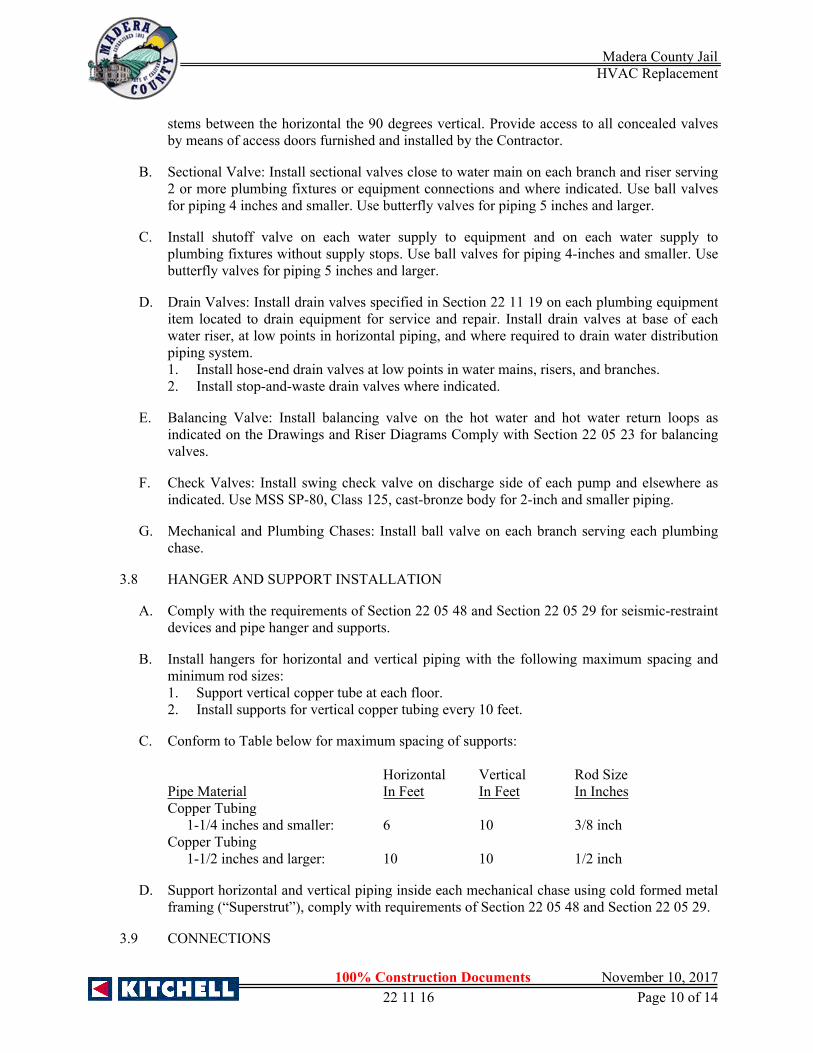
Madera County Jail HVAC Replacement
100% Construction Documents November 10, 201722 11 16 Page 10 of 14
stems between the horizontal the 90 degrees vertical. Provide access to all concealed valves by means of access doors furnished and installed by the Contractor.
B. Sectional Valve: Install sectional valves close to water main on each branch and riser serving 2 or more plumbing fixtures or equipment connections and where indicated. Use ball valves for piping 4 inches and smaller. Use butterfly valves for piping 5 inches and larger.
C. Install shutoff valve on each water supply to equipment and on each water supply to plumbing fixtures without supply stops. Use ball valves for piping 4-inches and smaller. Use butterfly valves for piping 5 inches and larger.
D. Drain Valves: Install drain valves specified in Section 22 11 19 on each plumbing equipment item located to drain equipment for service and repair. Install drain valves at base of each water riser, at low points in horizontal piping, and where required to drain water distribution piping system.1. Install hose-end drain valves at low points in water mains, risers, and branches.2. Install stop-and-waste drain valves where indicated.
E. Balancing Valve: Install balancing valve on the hot water and hot water return loops as indicated on the Drawings and Riser Diagrams Comply with Section 22 05 23 for balancing valves.
F. Check Valves: Install swing check valve on discharge side of each pump and elsewhere as indicated. Use MSS SP-80, Class 125, cast-bronze body for 2-inch and smaller piping.
G. Mechanical and Plumbing Chases: Install ball valve on each branch serving each plumbing chase.
3.8 HANGER AND SUPPORT INSTALLATION
A. Comply with the requirements of Section 22 05 48 and Section 22 05 29 for seismic-restraint devices and pipe hanger and supports.
B. Install hangers for horizontal and vertical piping with the following maximum spacing and minimum rod sizes:1. Support vertical copper tube at each floor.2. Install supports for vertical copper tubing every 10 feet.
C. Conform to Table below for maximum spacing of supports:
Horizontal Vertical Rod SizePipe Material In Feet In Feet In InchesCopper Tubing
1-1/4 inches and smaller: 6 10 3/8 inchCopper Tubing 1-1/2 inches and larger: 10 10 1/2 inch
D. Support horizontal and vertical piping inside each mechanical chase using cold formed metal framing (“Superstrut”), comply with requirements of Section 22 05 48 and Section 22 05 29.
3.9 CONNECTIONS

Madera County Jail HVAC Replacement
100% Construction Documents November 10, 201722 11 16 Page 11 of 14
A. Drawings indicate general arrangement of piping, fittings, and specialties.
B. Install piping adjacent to equipment and machines to allow service and maintenance.
C. Connect domestic water distribution piping to exterior water service entrance piping. Use transition fitting to join dissimilar piping materials.
D. Connect domestic water piping to the following:1. Water Heaters: Install cold-water supply and hot-water outlet piping in sizes indicated,
but not smaller than sizes of water heater connections.2. Plumbing Fixtures: Install cold and hot water supply piping in sizes indicated, but not
smaller than required by the latest edition of California Plumbing Code (CPC) and/or authorities having jurisdiction. Refer to Section 22 11 19.
3. Equipment: Connect cold and hot water supply piping to equipment as indicated, but not smaller than equipment connections and as required by CPC. Provide ball valve and union for each connection; provide drain valve on drain connection. Use flanges instead of unions for 5-inches and larger.
3.10 FIELD QUALITY CONTROL
A. Inspect domestic water piping as follows:1. Do not enclose, cover, or put piping into operation until all piping is inspected and
approved by local plumbing official and/or authority having jurisdiction.2. During progress of the installation, notify local plumbing official and/or authority having
jurisdiction at least 24 hours prior to time inspection must be made. Perform tests specified below in presence of the local plumbing official and/or authority having jurisdiction:a. Roughing-in Inspection: Arrange for inspection of piping system before concealing
or closing-in after roughing-in and prior to setting fixtures.b. Final Inspection: Arrange for final inspection by local plumbing official and/or
authority having jurisdiction to observe tests and to ensure all systems are in compliance with requirements of the latest edition of California Plumbing Code.
3. Reinspection: When a plumbing official finds that a piping system will not pass test or inspection, Contractor must make the required corrections and arrange for reinspection by the plumbing official.
4. Reports: Prepare inspection reports and have them signed by the local plumbing official and/or authority having jurisdiction. A copy of all inspection reports to be included in the O & M Manuals.
5. Provide written report to Architect and Engineer that all copper piping installed below ground and inside grout filled block walls have been coated and wrapped with approved pipe wrap. Written report must be included in the O & M Manuals.
B. Test domestic water distribution piping as follows:1. Test for leaks and defects in new water distribution piping system and parts of existing
piping that have been altered, extended, or repaired. If testing is performed in segments, submit separate report for each test, complete with diagram of portion of piping tested.
2. Leave uncovered and unconcealed new, altered, extended, or replaced domestic water distribution piping until it has been tested and approved. Expose work that was covered or concealed before it has been tested and approved for testing.
Madera County Jail HVAC Replacement
100% Construction Documents November 10, 201722 11 16 Page 12 of 14
3. Cap and subject piping to static water pressure of 50 psig above operating pressure, without exceeding pressure rating of piping system materials. Isolate test source and allow to stand for four hours. Leaks and loss in test pressure constitute defects that must be repaired.
4. Repair leaks and defects with new materials and retest system or portion thereof until satisfactory results are obtained.
5. Prepare reports for tests and required corrective action.
3.11 ADJUSTING
A. Adjust balancing valves in hot-water system to provide adequate flow.1. Manually adjust ball-type balancing valves in hot-water-circulation return piping to
provide flow of hot water in each branch.2. Adjust calibrated balancing valves to flows indicated on the Plumbing Drawings or
Domestic Water Piping Diagram.
3.12 DISINFECTION OF DOMESTIC WATER PIPING SYSTEM
A. Prior to starting work, verify system is complete and clean.
B. Ensure pH of water to be treated is between 7.4 and 7.6 by adding alkali (caustic soda or soda ash) or acid (hydrochloric).
C. Disinfect potable domestic water distribution piping as follows:1. Purge new domestic water distribution piping systems before using.2. Use purging and disinfecting procedures prescribed by authorities having jurisdiction or,
if methods are not prescribed by that authority, the procedures described in either AWWA C651 or AWWA C652 or as described below:a. Flush piping system with clean, potable water until dirty water does not appear at
outlets.b. Fill and isolate system according to either of the following:
1) Fill system or part thereof with water/chlorine solution with at least 50 ppm (50 mg/L) of chlorine. Isolate with valves and allow to stand for 24 hours.
2) Fill system or part thereof with water/chlorine solution with at least 200 ppm (200 mg/L) of chlorine. Isolate and allow to stand for three hours.
c. Flush system with clean, potable water until no chlorine is in water coming from system after the standing time.
d. Bleed water from outlets to ensure distribution and test for disinfectant residual at minimum 15 of outlets.
e. If final disinfectant residual test less than 25 mg/L, repeat treatment.f. Flush disinfectant from system until residual equal to that of incoming water or
1.0mg/L.g. Take samples no sooner than twenty-four (24) hours after flushing, from 10 percent
of outlets and from water entry, and analyze in accordance with AWWA C651. Provide laboratory results to Owner Representative. Obtain approval from local health department.
D. Prepare and submit reports of purging and disinfecting activities.
E. Completely flush all domestic hot and cold water risers to eliminate all debris in the lines before using any flush valves.

Madera County Jail HVAC Replacement
100% Construction Documents November 10, 201722 11 16 Page 13 of 14
F. Clean interior of domestic water piping system. Remove dirt and debris as work progresses.
3.13 STARTUP SERVICES
A. Verify incoming water pressure and temperature.
B. Replace all strainer screens with new at all mechanical and plumbing equipment.
C. Fill water systems. Check potable water expansion tanks to determine that they are not air bound and that system is completely full of water.
D. Before operating systems, perform these steps.1. Close drain valves, hydrants, and hose bibbs.2. Open all valves to full open position.3. Open throttling valves to proper setting.4. Remove plugs used during testing of piping systems and plugs used for temporary
sealing of piping during installation.5. Remove and clean strainer screens and aerators. Close drain valves and replace drain
plugs.6. Remove filter cartridges from housings and verify that cartridges are as specified for
application where used, clean, and ready for use.
E. Check plumbing equipment and verify proper settings, adjustments, and operation. Do not operate water heaters before filling with water.
F. Check plumbing specialties and verify proper settings, adjustments, and operation.
3.14 PROTECTION
A. Protect piping during remainder of construction period to avoid clogging with dirt and debris and to prevent damage from traffic and construction work.
B. Place plugs in ends of uncompleted piping at end of day or when work stops.
END OF SECTION 22 11 16

Madera County Jail HVAC Replacement
100% Construction Documents November 10, 201722 11 16 Page 14 of 14
THIS PAGE LEFT BLANK

Madera County Jail HVAC Replacement
100% Construction Documents November 10, 201722 11 19 Page 1 of 6
SECTION 22 11 19 - DOMESTIC WATER PIPING SPECIALTIES
PART 1 GENERAL
1.1 SUMMARY
A. Section Includes:1. Backflow preventers.2. Water hammer arrester.3. Flashing materials.
B. Related Sections:1. Section 22 05 00 - Common Work Results for Plumbing.2. Section 22 05 23 - General-Duty Valves for Plumbing Piping.3. Section 22 11 13 - Facility Water Distribution Piping.4. Section 22 11 16 - Domestic Water Piping.
1.2 SYSTEM PERFORMANCE REQUIREMENTS
A. Provide components and installation capable of producing piping systems with following minimum working-pressure ratings, unless otherwise indicated:1. Domestic Water Piping, Below Ground: 160 psig.2. Domestic Water Piping, Above Ground: 125 psig.
1.3 SUBMITTALS
A. General: Submit the following in accordance with Conditions of the Contract and Division 1.
B. Product Data: Include rated capacities and shipping, installed, and operating weights. Indicate materials, finishes, dimensions, required clearances, and methods of assembly of components; and piping and wiring connections for the following:1. Backflow Preventers.2. Water Hammer Arresters.3. Flashing Materials.
C. Field test reports.
D. Maintenance Data for inclusion in operating and maintenance manuals as specified in Division for the following:1. Backflow Preventers.
1.4 QUALITY ASSURANCE
A. Design Concept: Drawings indicate capacities, size, profiles, and dimensional requirements of plumbing specialties and system components. Components having equal performance characteristics that deviate from the indicated size and dimensions may be considered, provided such deviations do not change the design concept or intended performance. Refer to Division 1.
B. Plumbing specialties must bear label, stamp, or other markings of specified testing agency.

Madera County Jail HVAC Replacement
100% Construction Documents November 10, 201722 11 19 Page 2 of 6
C. Electrical Components, Devices, and Accessories: Listed and labeled as defined in CEC, Article 100, by a testing agency acceptable to authorities having jurisdiction, and marked for intended use.
D. ASME Compliance: Comply with ASME B31.9, “Building Services Piping,” for piping materials and installation.
E. NSF Compliance:1. Comply with NSF 61, “Drinking Water System Components-Health Effects, Sections 1
through 9,” for potable domestic water plumbing specialties.
1.5 EXTRA MATERIALS
A. Deliver extra materials to Owner. Furnish extra materials matching products installed as described below. Package them with protective covering for storage and identify with labels clearly describing contents.
B. Operating Keys (Handles): Furnish 1 extra key for each key-operated hose bibb and hydrant installed.
PART 2 PRODUCTS
2.1 MANUFACTURERS
A. Manufacturers: Subject to compliance with requirements, provide products by one of the following:1. Backflow Preventers:
a. Conbraco Industries, Inc.b. Watts Industries, Inc.; Water Products Div.c. Zurn Industries, Inc.; Wilkins Div.
2. Water Hammer Arresters:a. Jay R.Smith Mfg. Co., Div., Smith Industries, Inc.b. Precision Plumbing Products, Inc.c. Sioux Chief Manufacturing Co., Inc.d. Zurn by Hydromechanics Div., Zurn Industries, Inc.
3. Firestop Sleeve Penetration Systems:a. Hilti Fire Stop Systems.b. 3-M Fire Stop Systems.c. Approved Equal.
2.2 BACKFLOW PREVENTERS
A. Hose Connection Vacuum Breakers: ASSE 1011, nickel plated, with nonremovable and manual drain features, and ASME B1.20.7 garden-hose threads on outlet. Units attached to rough-bronze-finish hose connections may be rough bronze.
B. Reduced-Pressure-Principle Backflow Preventer. ASSE 1013, consisting of (OS&Y) gate valves on inlet and outlet and strainer on inlet. Include test cocks and pressure-differential relief valve having ASME A112.1.2 air-gap fitting located between 2 positive-seating check valves for continuous pressure application.

Madera County Jail HVAC Replacement
100% Construction Documents November 10, 201722 11 19 Page 3 of 6
1. Pressure Loss: 12 psig maximum, through middle 1/3 of flow range.2. Pressure Loss: 5 psig maximum, through middle 1/3 of flow range.
2.3 WATER HAMMER ARRESTERS
A. Water Hammer Arresters: ASSE 1010, or PDl WH-201, bellows or piston type with pressurized cushioning chamber. Sizes are based on water-supply fixture units, PDl WH-201 sizes “A” through “F.”
B. Roof Flashing Assemblies: Manufactured assembly consisting of 4-psf lead flashing collar with boot and skirt extending at least 8 inches from pipe, with galvanized steel boot reinforcement and counter flashing fitting.1. Option 1: Open top.
2.4 FLASHING MATERIALS
A. Lead: ASTM B 749, Type L51121, copper-bearing sheet, at least 4 psf (0.0625-inch thick) for general use, and at least 6 psf (0.0937-inch thick) for burning (welding), except as otherwise indicated.
2.5 MISCELLANEOUS PIPING SPECIALTIES
A. Piping specialties such as escutcheons, dielectric fittings, sleeves, and sleeve seals are specified in Section 22 05 00.
PART 3 EXECUTION
3.1 INSTALLATION
A. Comply with Section 22 05 00 for piping joining materials, joint construction, and basic installation requirements.
3.2 PIPING SPECIALTY INSTALLATION
A. Install backflow preventers of type, size, and, and capacity indicated, at each water supply connection to mechanical equipment and systems, hot and cold water to washing machines and cold water to garbage disposal at dishwashing machine; and to other equipment and systems as indicated. Comply with plumbing code and authority having jurisdiction. Locate in same room as equipment being connected. Install air-gap fitting on units having atmospheric vent connection and pipe relief outlet drain to nearest floor drain. Do not install bypass around backflow preventer.
B. Install strainers on supply side of each control valve, pressure-regulating valve, and solenoid valve, and where indicated.
C. Install water hammer arrestors on all fixture groups of 3 or more fixtures, Water hammer arrestors to be sized according to P.D.I. Standard, see Table below:
P.D.I. Symbol A B C D E FFixture Unit Rating 1-11 12-32 33-60 61-113 114-154 755-330

Madera County Jail HVAC Replacement
100% Construction Documents November 10, 201722 11 19 Page 4 of 6
D. Placement of arrestors on fixture branch line up to 20 feet in length should be between the last two fixtures. On fixture branch line over 20 feet in length two arrestors should be used with the second arrestor placed at the approximate midpoint of the line. The total sum of the fixture unit ratings of the water hammer arrestor should be equal to or greater than the total fixture unit of the branch line.
3.3 CONNECTIONS
A. Supply Runouts to Fixtures: Install hot- and cold-water supply piping runouts to fixtures of sizes indicated but not smaller than required by plumbing code.
B. Electrical Connections: Power wiring and disconnect switches are specified in Division 26.1. Grounding: Connect unit components to ground according to the National Electrical
Code and Division 26 Section 26 05 26.
3.4 FLASHING INSTALLATION
A. Provide flashing Manufactured in a single piece except where large pans, sumps; or other drainage shapes are required.
B. Install 4-psf lead flashing or 16-oz. per sq. ft. copper, except when another weight or material is specified.
C. Install 8-psf lead flashing or heavier where burning (welding) of lead sheets is required.
D. Install sheet flashing on pipes, sleeves, and specialties passing through or embedded in floors and roofs with membrane waterproofing.1. Pipe Flashing: Sleeve type, matching pipe size, with minimum sleeve length of 10
inches, and skirt or flange extending at least 8 inches around pipe.2. Sleeve Flashing: Flat sheet, with skirt or flange extending at least 8 inches around
sleeve.3. Embedded Specialty Flashing: Flat sheet, with skirt or flange extending at least 3 inches
around specialty.
E. Set flashing on floors and roofs in solid coating of bituminous cement.
F. Secure flashing into sleeve and specialty clamping ring or device.
G. Install flashing for piping passing through roofs with counter flashing or commercially made flashing fittings, according to Division 7 Section 07 84 13.
H. Extend flashing up vent pipe passing through roofs and turn down into pipe or secure flashing into cast-iron sleeve having calking recess.
I. Fabricate and install lead sheet flashing and pans, sumps, and other drainage shapes as indicated. Install drain connection when indicated.
J. Fabricate and install copper sheet flashing and pans, sumps, and other drainage shapes as indicated. Install drain connection when indicated.
K. Fabricate and install galvanized-steel sheet flashing and pans, sumps, and other drainage shapes as indicated. Install drain connection when indicated.
Madera County Jail HVAC Replacement
100% Construction Documents November 10, 201722 11 19 Page 5 of 6
L. Fabricate and install elastic-membrane sheet flashing and pans, sumps, and other drainage shapes as indicated. Install drain connection when indicated.
3.5 LABELING AND IDENTIFYING
A. Equipment Nameplates and Signs: Install engraved plastic-laminate equipment nameplate or sign on or near each backflow preventer.1. Text: Distinguish among multiple units, inform operator of operational requirements,
indicate safety and emergency precautions, and warn of hazards and improper operations, in addition to identifying unit.
2. Requirements for nameplates and signs are specified in Section 22 05 00.
3.6 PROTECTION
A. Place plugs in ends of uncompleted piping at end of each day or when work stops.
3.7 STARTUP SERVICES
A. Preparation: Perform the following checks before start-up:1. Systems tests are complete.2. Damaged and defective specialties and accessories have been replaced or repaired.3. There is clear space for servicing of specialties.
B. Before operating systems, perform these steps:1. Close drain valves, hydrants, and hose bibbs.2. Open valves to full open position.3. Remove and clean strainers.
3.8 ADJUSTING
A. Adjust operation and correct deficiencies discovered during startup services.
3.9 DOMESTIC WATER PIPING SPECIALTIES SCHEDULES
A. Provide specialties as scheduled on the following “Data Sheets.” Each Data Sheet begins with a new page.
END OF SECTION 22 11 19

Madera County Jail HVAC Replacement
100% Construction Documents November 10, 201722 11 19 Page 6 of 6
THIS PAGE LEFT BLANK

Madera County Jail HVAC Replacement
100% Construction Documents November 10, 201722 35 00 Page 1 of 4
SECTION 22 35 00 – DOMESTIC WATER HEAT EXCHANGERS
PART 1 GENERAL
1.1 RELATED DOCUMENTS
A. Drawings and general provisions of the Contract, including General and Supplementary Conditions and Division 01 Specification Sections, apply to this Section.
1.2 SUMMARY
A. This Section includes the following heat exchangers:1. Noncirculating, storage heat exchangers.2. Heat-exchanger accessories.SUBMITTALS
1.3 SUBMITTALS
A. Submit under provisions of Division 1.
B. Product Data: For each type and size of heat exchanger indicated. Include rated capacities, operating characteristics, furnished specialties, and accessories.
1.4 QUALITY ASSURANCE
A. Source Limitations: Obtain same type of heat exchangers through one source from a single manufacturer.
B. Operating Product Options: Drawings indicate size, profiles, and dimensional requirements of heat exchangers and are based on the specific system indicated. Refer to Division 01 Section "Product Requirements."
C. Electrical Components, Devices, and Accessories: Listed and labeled as defined in NFPA 70, Article 100, by a testing agency acceptable to authorities having jurisdiction, and marked for intended use.
D. ASME Compliance: Where ASME-code construction is indicated, fabricate and label heat- exchanger storage tanks to comply with ASME Boiler and Pressure Vessel Code: Section VIII, Division 1.
E. Comply with NSF 61, "Drinking Water System Components - Health Effects; Sections 1 through 9" for all components that will be in contact with water.
1.5 QUALITY ASSURANCE
A. Coordinate size and location of concrete bases with Architectural and Structural Drawings.

Madera County Jail HVAC Replacement
100% Construction Documents November 10, 201722 35 00 Page 2 of 4
PART 2 PRODUCTS
2.1 MANUFACTURERS
A. In other Part 2 articles where titles below introduce lists, the following requirements apply to product selection:1. Available Manufacturers: Subject to compliance with requirements, manufacturers
offering products that may be incorporated into the Work include, but are not limited to, manufacturers specified.
2.2 NONCIRCULATING STORAGE HEAT EXCHANGERS
A. Storage Heat Exchangers:1. Available Manufacturers:
a. Cemline Corporation.b. PVI Industries, LLC.c. Smith, A. O. Water Products Company.
2. Description: Assembly of hot-water storage tank with separate heat-exchanger coil; controls; and specialties for heating domestic water with heating hot water in coil.
3. Storage Tank Construction: ASME-code steel with 125-psig working-pressure rating. Include nozzle and head for heat-exchanger tube coil.a. Configuration: Vertical.b. Manhole: 11 by 15 inches in sidewall of vertical storage tank shell.c. Tappings: Factory fabricated of materials compatible with tank. Attach tappings to
tank before testing and labeling.d. NPS 2 and Smaller: Threaded ends according to ASME B1.20.1.e. NPS 2-1/2 and Larger: Flanged ends according to ASME B16.5 for steel and
stainless-steel flanges, and according to ASME B16.24 for copper and copper-alloy flanges.
f. Lining: Nickel plate complying with NSF 61 barrier materials for potable-water tank linings, including extending lining into and through tank fittings and outlets.
g. Anode Rods: Factory installed, magnesium.h. Insulation: Complying with ASHRAE/IESNA 90.1, unless otherwise indicated, and
suitable for operating temperature. Surround entire storage tank and nozzle except connections and controls.
4. Heat-Exchanger Coil: NPS 1-1/4 diameter, copper or copper-alloy, U tubes with tube sheet and supporting baffles.a. Heat-Exchanger Pressure Rating: Equal to or greater than heating-fluid supply
pressure.5. Temperature Control: Adjustable temperature aquastat, mounted in storage tank shell
head, unless otherwise indicated.6. Relief Valves: ASME rated and stamped and complying with ASME PTC 25.3, for
combination temperature and pressure relief valves. Include one or more relief valves with total relieving capacity at least as great as heat input, and include pressure setting less than working-pressure rating of heat exchanger. Select one relief valve with sensing element that extends into storage tank.
7. Support: Factory mounted on skids.
Madera County Jail HVAC Replacement
100% Construction Documents November 10, 201722 35 00 Page 3 of 4
8. Capacity and Characteristics:a. See Construction Drawings.b. Heating Hot-Water Supply:
1) Inlet Temperature: 180 °F2) Outlet Temperature: 150 °F
2.3 HEAT-EXCHANGER ACCESSORIES
A. Water Combination Temperature and Pressure Relief Valves: ASME rated and stamped and complying with ASME PTC 25.3. Include relieving capacity at least as great as heat input, and include pressure setting less than working-pressure rating of heat exchanger. Select relief valves with sensing element that extends into heat-exchanger storage tank.
B. Pressure Relief Valves: ASME rated and stamped and complying with ASME PTC 25.3. Include pressure setting less than working-pressure rating of heat exchanger.
C. Piping-Type Heat Traps: Field-fabricated piping arrangement according to ASHRAE/IESNA 90.1 or ASHRAE 90.2.
2.4 SOURCE QUALITY CONTROL
A. Test and inspect heat-exchanger storage tanks, specified to be ASME-code construction, according to ASME Boiler and Pressure Vessel Code.
B. Hydrostatically test commercial heat-exchanger storage tanks before shipment to minimum of one and one-half times pressure rating.
C. Prepare test reports.
PART 3 EXECUTION
3.1 HEAT-EXCHANGER INSTALLATION
A. Install heat exchangers on concrete bases.1. Concrete base construction requirements are specified in Division 22 Section "Common
Work Results for Plumbing."
B. Install heat exchangers level and plumb, according to layout drawings, original design, and referenced standards. Maintain manufacturer's recommended clearances. Arrange units so controls and devices needing service are accessible.
C. Anchor heat exchangers to substrate.
D. Install temperature and pressure relief valves in top portion of storage tank shells of heat exchangers with domestic water storage. Use relief valves with sensing elements that extend into shells. Extend relief-valve outlet, with drain piping same as water piping in continuous downward pitch, and discharge by positive air gap onto closest floor drain.
E. Install heat-exchanger drain piping as indirect waste to spill by positive air gap into open drains or over floor drains. Install hose-end drain valves at low points in water piping for heat

Madera County Jail HVAC Replacement
100% Construction Documents November 10, 201722 35 00 Page 4 of 4
exchangers that do not have tank drains. Refer to Division 22 Section "Domestic Water Piping Specialties" for hose-end drain valves.
F. Install thermometer on each heat-exchanger domestic-water inlet and outlet piping, and install thermometer on each heat-exchanger heating-fluid inlet and outlet piping. Refer to Division 22 Section "Meters and Gages for Plumbing Piping" for thermometers.
G. Install pressure gages on heat-exchanger heating-fluid piping. Refer to Division 22 Section "Meters and Gages for Plumbing Piping" for pressure gages.
H. Fill heat exchangers with water.
3.2 CONNECTIONS
A. Piping installation requirements are specified in other Division 22 Sections. Drawings indicate general arrangement of piping, fittings, and specialties.
B. Install piping adjacent to heat exchangers to allow service and maintenance. Arrange piping for easy removal of heat exchangers.
C. Ground equipment according to Division 26 Section "Grounding and Bonding for Electrical Systems."
D. Connect wiring according to Division 26 Section "Low-Voltage Electrical Power Conductors and Cables."
3.3 FIELD QUALITY CONTROL
A. Manufacturer's Field Service: Engage a factory-authorized service representative to inspect field-assembled components and equipment installation, including connections. Report results in writing.
B. Perform the following field tests and inspections and prepare test reports:\1. Leak Test: After installation, test for leaks. Repair leaks and retest until no leaks exist.2. Operational Test: After electrical circuitry has been energized, confirm proper operation.3. Test and adjust controls and safeties. Replace damaged and malfunctioning controls and
equipment.
C. Remove and replace heat exchangers that do not pass tests and inspections and retest as specified above.
3.4 DEMONSTRATION
A. Engage a factory-authorized service representative to train Owner's maintenance personnel to adjust, operate, and maintain heat exchangers. Refer to Division 01 Section "Demonstration and Training."
END OF SECTION 22 35 00
Madera County Jail HVAC Replacement
100% Construction Documents November 10, 2017
23 05 00 Page 1 of 18
SECTION 23 05 00 - COMMON WORK RESULTS FOR HVAC
PART 1 GENERAL
1.1 SUMMARY
A. Section Includes:1. Piping materials and installation common to most piping systems.2. Dielectric unions and flanges.3. Escutcheons.4. Mechanical sleeve seals.5. Sleeves.6. Motors and drives.7. Combination magnetic starters.8. Equipment guards.9. Equipment installation requirements common to equipment Sections.10. Adjusting and c leaning.
B. Related Sections:1. Section 03 30 00 - Cast-in-Place Concrete.2. Section 05 05 55 - Tamper Proof Metal Fastenings.3. Section 07 84 13 - Firestopping.4. Section 07 92 00 - Joint Sealant.5. Section 08 31 10 - Access Doors and Frames.6. Section 09 90 13 - Painting and Coating7. Section 23 05 19 - Meters and Gauges for HVAC Piping.8. Section 23 05 29 - Hangers and Supports for HVAC Piping and Equipment.9. Section 23 05 48 - Vibration and Seismic Controls for HVAC Piping and Equipment.10. Section 23 05 53 - Identification for HVAC Piping and Equipment.11. Section 23 05 93 -Testing, Adjusting, and Balancing for HVAC12. Section 23 07 00 - HVAC Insulation.
1.2 REFERENCES
A. American Society of Mechanical Engineers (ASME).1. ASME B31.1 - Power Piping.2. ASME B31.9 - Building Services Piping.3. ASME B16.20 - Metallic Gaskets for Pipe Flanges: Ring Joint Spiral Wound and
Jacketed.4. ASME B16.10 - Face to Face and End to End Dimensions of Valves.5. ASME B16.34 - Valves Flanged, Threaded and Welding End.
B. National Certified Pipe Welding Bureau (NCPWB).
C. Standard Procedure Specifications
D. ASME SEC IX - ASME Boiler and Pressure Vessel Code - Section IX: Welding and Brazing Qualifications.
Madera County Jail HVAC Replacement
100% Construction Documents November 10, 2017
23 05 00 Page 2 of 18
E. ANSI Standards.1. ANSI B16.20 - Metallic Gaskets for Pipe Flanges: Ring Joint Spiral Wound and
Jacketed.
F. AWWA Standards1. AWWA C111/A21.11-07: Rubber-Gasket Joints for Ductile–Iron Pressure Pipe and
Fittings
G. MSS Compliance:1. MSS SP-25 - Marking System for Valves, Fittings, Flanges and Unions.2. MSS SP-72 - Ball Valves with Flanged or Butt-Welding Ends for General Service.3. MSS SP-80 - Bronze Gate, Globe, Angle and Check Valves.4. MSS SP-67 - Butterfly Valves.5. MSS SP-70 - Cast Iron Gate Valves, Flanged and Threaded Ends.6. MSS SP-85 - Gray Iron Globe and Angle Valves, Flanged and Threaded Ends.7. MSS SP-78 - Gray Iron Plug Valves Flanged and Threaded Ends.8. MSS SP-71 - Gray Iron Swing Check Valves, Flanged and Threaded Ends.
H. FCI Compliance:1. FCI 73-1 - Pressure Rating Standard for “Y” Type Strainers.2. FCI 78-1- Pressure Rating Standard for Pipeline Strainers other than “Y Type.
1.3 DEFINITIONS
A. “Piping” includes, in addition to pipe, all fittings, flanges, valves, hangers and other accessories related to such piping.
B. “Wiring” includes in addition to conductors, all raceway, conduit, fittings, boxes, switches, hangers and other accessories related to such wiring.
C. “Concealed” means hidden from sight in chases, furred spaces, shafts, hung ceilings or embedded in construction.
D. “Exposed” means not installed underground or “concealed” as defined above.
E. “Provide” means to furnish and install.
1.4 SUBMITTALS
A. General1. Comply with the requirements of Division 1 and the specific requirements of the
Sections of Division 23.2. Submit all similar equipment together as part of the same submittal. For example:
a. All air-handling units fans must be contained in the same submittal.b. All pumps must be contained in the same submittal.
3. Contractor must review all submittals prepared by each supplier and mark all copies as acceptable to the Contractor. This acceptance will signify that all required service connections are shown and in the proper location to meet the installation requirements and that the equipment can fit in the space allowed.
4. Do not order equipment until submittals have been reviewed and approved by the Owner Representative.

Madera County Jail HVAC Replacement
100% Construction Documents November 10, 2017
23 05 00 Page 3 of 18
5. Each item submitted must be labeled or identified the same as on the Drawings.6. Mark submittal “Exactly as Specified” or accompanied by a letter from the supplier
explaining in detail what difference, if any, exists between the submitted item and the specified item. Failure to point out the differences will be considered cause for disapproval. The Owner Representative will not assume any responsibility for differences concealed or otherwise not brought to their attention, and the Contractor will be required to correct any deficiencies or differences discovered at a later date, and assume responsibility for any delays, damage, and/or expenses incurred by others due to such action.
7. Brands or trade names are mentioned to set standards of quality only; use no substitute materials, however, unless approved in writing by the Owner Representative. Approval of substitute materials does not relieve the Contractor of responsibility for providing a workable and functioning system as specified.
8. Submittals will be checked for general conformance with the design concept but acceptance by the Owner Representative in no manner is meant to verify that dimensions, quantities, or location of services are as necessary to meet the job requirements. This remains the responsibility of the Contractor.
B. Shop Drawings1. General: Prepare and submit plans, sections, details and diagrams to required scales for
specified areas. Drawings must be coordinated, dimensioned and indicate equipment, piping, and ductwork in relation to architectural and structural features as well as other building systems. Include Minor piping, drains, air vents, etc. Indicate exact locations and elevations of valves, piping specialties, access doors, dampers etc.
2. Required Drawings: Prepare and submit drawings for all areas and all mechanical work. Scale must be minimum 3/8” = 1’-0” in mechanical rooms, fan rooms, and mechanical areas, and minimum 1/4” = 1’-0” elsewhere.
C. Coordination Drawings1. General: Coordination drawings are defined as “shop drawings” which also indicate, on
the same drawings, the major utilities of all other trades. “Coordination Drawings” must indicate location and elevations of structural slabs and beams, architectural elements, domestic water piping, plumbing vents, sanitary drains, storm drains, fire protection piping, lighting fixtures, electrical conduits (2-inch and larger), ductwork, penetrations of walls and roof, fire dampers, fire/smoke dampers, automatic dampers, terminal boxes, air outlets, access panels, ceiling mounted equipment and controls, gas piping, flues, fans, air handling equipment, etc.
2. Submit coordination drawings for the following:a. Entire housing building.b. Other areas for which space is limited.
3. It is the intent of the coordination drawings to ensure coordination of all major utilities, prior to the start of installation. This is a substantial effort which will require careful and detailed coordination and planning to ensure appropriate information is available, from all trades, in a timely manner. The coordination drawing effort must be integrated into the project schedule and monitored to ensure conformance.
4. Conflicts between trades, which cannot be resolved through generally accepted practice of coordination between trades, must be clouded on the coordination drawings and an appropriate description of the problem noted for review by the Owner Representative.

Madera County Jail HVAC Replacement
100% Construction Documents November 10, 2017
23 05 00 Page 4 of 18
5. Nonconforming M/E work installed within designated coordination areas is subject to removal and replacement by installing contractor at no additional cost to Owner.
6. Coordination drawings must be signed and dated by individual trade constrictors. By act of signature and submittal of singular combined coordination drawings, each trade contractor acknowledges coordination of their portion of the Work with all other plumbing, mechanical, electrical, architectural, and structural work contractors.
D. Product Data1. General: Manufacturer’s specifications, data sheets, certified drawings, and installation
instructions. Include physical and performance data such as weights, sizes, capacities, required clearances, performance curves, acoustical characteristics, finishes, color selection, location and size of field connections, and accessories. Include certified drawings on major equipment such as boilers, water chillers, cooling towers, controls, pumps, and tanks.
2. Motors: Submit manufacturer’s name, type, RPM, HP (KW), full load amps, efficiency, and power factor.
3. Part Load Performance: Submit equipment data to indicate performance characteristics throughout ranges of possible load conditions.
4. Include operating weight and location of center of gravity of each item of equipment in manufacturer’s cut sheet for purposes of seismic calculation.
5. Pipes and Pipe Fittings: Submit schedule showing pipe material data, sizes, fitting valve type k factor, working pressure for each service.
6. Submit valve schedule showing manufacturer’s figure number, size, location, and valve features for each required valve.
7. Submit schedule showing manufacturer’s figure number, size, location, and features for each required piping specialty.a. Strainers: include pressure drop or chart for each type and size.
8. Meters and gauges: include scale range for each service.
E. Test Reports1. Manufacturer’s Tests
a. Factory Tests: As specified for specific equipment.b. Field Tests: As specified.
2. System Pressure Tests: As specified under “Testing” article. Test log of pressure tests on each system. Indicate date of test, scope of test, test pressure, duration, and observers.
3. Balancing Reports: As specified under Section 23 05 93.
F. Certification1. Seismic Restraints: As specified under Sections 23 05 29 and 23 05 48.2. Controls: As specified under Section 23 09 24.3. Welding Certificates.4. Brazing Certificates.
G. Operating and Maintenance Manuals: Include, but not limited to, the following:1. List of all equipment with Manufacturer’s name, model number, and local
representative, service facilities and normal channel of supply for each item. Include phone number and address of service facilities
2. System Description: Description of start-up, operating, and shutdown procedures.3. Controls: Diagrams and description of operation sequence of each system.

Madera County Jail HVAC Replacement
100% Construction Documents November 10, 2017
23 05 00 Page 5 of 18
4. Equipment: Manufacturer’s brochures, ratings, certified shop drawings, lubrication charts and data, parts lists with part numbers, and belt and sheave data. Mark each sheet with equipment identification number and actual installed condition.
5. Materials and Accessories: Manufacturer’s brochures parts list with part numbers and lubrication data where applicable. Mark each sheet with equipment identification number or system and location of installation; and to specifically identify which options are provided (in case where data sheet shows multiple options).
6. Certificate of factory tests, field tests and code compliance as specified.7. Wiring and controls schematics.8. Trouble shooting directions.9. Maintenance procedures and frequencies.10. Description of special tools.11. Copies of warranties.12. Safety precautions.13. Emergency contingencies.
H. Record Documents1. Comply with the Conditions of the Contract and the requirements of Section 23 05 53.2. Indicate ductwork mains and branches, size and location, for both exterior and interior;
locations of dampers, control devices, filters, and terminal units requiring maintenance or repair.
3. Indicate mains and branches of piping systems, with valves and control devices located and numbered per valve schedule, concealed unions located, and with items requiring maintenance located (i.e. traps, strainers, expansion compensators, vents, etc.). Indicate actual inverts and horizontal locations of underground piping.
4. Indicate equipment locations (exposed and concealed), dimensioned from prominent building lines.
5. Identify approved substitutions, Contract Modifications, and actual equipment and materials installed.
I. Samples: When specified under applicable Sections.
1.5 DELIVERY, STORAGE, AND HANDLING
A. Provide factory-applied plastic end-caps on each length of pipe and tube. Maintain end-caps through shipping, storage and handling as required to prevent pipe-end damage and eliminate dirt and moisture from inside of pipe and tube.
B. Where possible, store pipe and tube inside and protected from weather. Where necessary to store outside, elevate above grade and enclose with durable, waterproof wrapping.
C. Protect flanges and fittings from moisture and dirt by inside storage and enclosure, or by packaging with durable, waterproof wrapping.
1.6 SUBSTITUTIONS
Madera County Jail HVAC Replacement
100% Construction Documents November 10, 2017
23 05 00 Page 6 of 18
A. General: 1. Base manufacturer is indicated in equipment schedules.2. In Specification, additional acceptable manufacturer(s) may be indicated.3. Other manufacturers, materials, or methods must not be used unless approved in writing
by the Owner Representative.4. The burden of proof as to the equality of any proposed substitute manufacturer, material,
or method must be upon the Contractor.5. The Owner Representative’s decision must be final.
B. Requests for substitution review and acceptance must be accomplished by table of comparison listing pertinent features of both specified and proposed materials, such as materials of construction, performance, dimensions, weights, replacement or maintenance access, motor type, horsepower, voltage, phase, service factor. Review of proposed substitutions will not be made until receipt of satisfactory comparison tabulation.
C. Submittal of substitutions must be limited to one proposal for each type or kind of item, unless otherwise permitted by the Owner Representative. If first proposed product submittal is rejected, Contractor must then submit the first-named or scheduled product.
D. Contractor must be responsible for all costs and coordination due to the substitution, such as impacts on electrical requirements, weight, openings in slabs and roofs, structural framing, housekeeping pad size, etc.
1.7 JOB CONDITIONS
A. Cause as little interference or interruption of existing utilities and services as possible. Schedule Work which will cause interference or interruption in advance with Construction Manager.
B. Examine Contract Documents to determine how other Work will affect execution of mechanical Work.
C. Determine and verify locations of all existing utilities.
D. Arrange for, coordinate, and pay costs incidental to providing utility company services indicated.
E. Establish lines and levels for each system and coordinate with other systems to prevent conflicts and maintain proper clearances and accessibility.
PART 2 PRODUCTS
2.1 PIPE, TUBE AND FITTINGS
A. Refer to individual Division 23 piping sections for pipe, tube, fitting materials joining methods. Comply with governing regulations.
2.2 MISCELLANEOUS PIPING MATERIALS/PRODUCTS

Madera County Jail HVAC Replacement
100% Construction Documents November 10, 2017
23 05 00 Page 7 of 18
A. Welding Materials: Provide welding materials to comply with installation requirements.1. Comply with Section II, Part C, ASME Boiler and Pressure Vessel Code for welding
materials.
B. Gaskets for Flanged Joints: ASME B16.21; full-faced for cast-iron flanges; raised-face for steel flanges, unless otherwise indicated.
2.3 PIPING SPECIALITIES
A. General: Provide factory-fabricated piping specialties recommended by manufacturer for use in service indicated. Provide piping specialties of types and pressure ratings indicated for each service or, if not indicated, provide proper selection as determined by Installer to comply with installation requirements. Provide sizes as indicated, and connections, which properly mate with pipe, tube, equipment connections. Where more than one type is indicated, selection is Installer’s option.
B. Dielectric Unions and Flanges1. General: Provide standard products recommended by manufacturer for use in service
indicated, which effectively isolate ferrous from non-ferrous piping (electrical conductance), prevent galvanic action, and stop corrosion. Pressure rating equal to or greater than that of nearby valves.
2. Manufacturer:a. B & K Industries, Inc. b. Capitol Mfg. Co.; Div. of Harsco Corp. c. Eclipse, Inc.d. Epco Sales, Inc.e. Perfection Corp.f. Rockford-Eclipse Div.g. Victaulic Clearflow.h. Calpico, Inc.
C. Thermometers: Refer to Section 23 05 19.
D. Thermometer Wells: Refer to Section 23 05 19.
E. Pressure Gauges: Refer to Section 23 05 19.
F. Pressure Gauge Cocks: Refer to Section 23 05 19.
G. Test Fittings: Refer to Section 23 05 19.
2.4 PIPE ESCUTCHEONS
A. General: Provide solid (not split-hinged) pipe escutcheons as specified herein with inside diameter closely fitting pipe outside diameter, or outside of pipe insulation where pipe is insulated. Select outside diameter of escutcheon to completely cover pipe penetration hole in floors, walls, or ceilings; and pipe sleeve extension, if any. Furnish pipe escutcheons with nickel or chrome finish for occupied areas, prime paint finish for unoccupied areas. All escutcheons must be vandal proof.

Madera County Jail HVAC Replacement
100% Construction Documents November 10, 2017
23 05 00 Page 8 of 18
B. Pipe Escutcheons for Moist Areas: For waterproof floors, and areas where water and condensation can be expected to accumulate, provide solid brass or solid sheet brass pipe escutcheons.
C. Pipe Escutcheons for Dry Areas: Provide solid sheet metal escutcheons.
D. Manufacturer: Chicago Specialty, Producers Specialty, Sanitary-Dash.
2.5 MECHANICAL SLEEVE SEALS
A. General: Modular mechanical type, consisting of interlocking synthetic rubber links shaped to continuously fill annular space between pipe and sleeve, connected with bolts and pressure plates which cause rubber sealing elements to expand when tightened, providing watertight seal and electrical insulation.
B. Sleeve: To be furnished by same manufacturer of seals; schedule 40 galvanized steel pipe or Century line sleeves, with integral anchor and waterstop collar.
C. Manufacturer: Thunderline Link Seal or Metraflex Metraseal.
2.6 FIRE BARRIER PENETRATION SEALS
A. Provide seals for any opening through fire-rated walls, floors, or ceilings used as passage for mechanical components such as piping or ductwork. 1. Piping: Provide fire stopping material as specified in Section 07 84 13.2. Ductwork: Provide fire damper or fire/smoke damper. For penetrations where fire
damper or fire/smoke damper is not required by code, provide fire stopping material as specified in Section 07 84 13.
2.7 FABRICATED PIPING SPECIALTIES
A. Pipe Sleeves: Provide pipe sleeves of one of the following:1. Sheet-Metal: Fabricate from galvanized sheet metal; round tube closed with snaplock
joint, welded spiral seams, or welded longitudinal joint. Fabricate from the following gauges:a. 3-inch and smaller: 0.040-inch/20 gauge thick.b. 4 to 6-inch: 0.064-inch/16 gauge thick.c. Over 6-inch: 0.079-inch/14 gauge thick.
2. Steel Pipe: See “Mechanical Sleeve Seals” article.
2.8 MOTORS AND DRIVES
A. Motor controls and power wiring.1. Provided as part of Division 26 work, unless indicated otherwise, including motor
control switches, starters, disconnects, conduit and wiring, except for low voltage control wiring required for temperature controls.
2. Where equipment is specified with factory pre-wired controls and is furnished instead with components shipped loose, mechanical contractor must be responsible for coordinating the complete installation and assume any additional costs.
3. See Section 23 09 24 for control wiring.
Madera County Jail HVAC Replacement
100% Construction Documents November 10, 2017
23 05 00 Page 9 of 18
B. Motors1. Ball or roller bearing type, high efficiency type, with starting and running characteristics
consistent with torque and speed requirements of driven machine.2. Use motors rated in accordance with NEMA performance standards to carry full
nameplate load continuously at maximum temperature rise of 72 degrees F above ambient with service factor of 1.15.
3. Motors driven by variable frequency drives must be rated for inverter duty and must meet the requirements of NEMA MG-1 part 31.4.4.2.
4. Where substitute manufacturers are provided with different control panels, starters, or electrical characteristics from scheduled equipment, contractor must coordinate complete installation and assume any additional costs.
5. Do not allow power requirements of driven machine to exceed nominal nameplate rating of motor furnished.
6. Do not include service factor when selecting motor horsepower.7. Motors exposed to moisture or rain must be totally enclosed, fan cooled (TEFC). Others
may be open drip proof (ODP), unless otherwise indicated.
C. Motor electrical power characteristics: 460 volt, 3 phase, 60 Hz for 1/2 HP and larger; 115 volt, 1 phase, 60 Hz for smaller than 1/2 HP, unless noted otherwise.
D. Efficiency1. Requirements apply to all motors, 1/2 HP and larger, except for refrigeration
compressors, and for fans which run only in emergency mode, such as chemical exhaust fans.
2. Ratings in accordance with IEEE 112b Rating Method. 3. Motors must be labeled as NEMA “Premium” Efficient, with efficiencies as follows,
based on 1750 RPM.;a. Motors with other than 1750 RPM must be same type motor as would meet
requirements for 1750 RPM motors.
E. Belt Drives1. Manufacturers: Browning, Gates, Woods, or Dayton.2. Belts: V-belt drives rated at 1-1/2 times the motor horsepower. High quality
commercial-grade rubber with polyester reinforcing.a. Provide two belts minimum for motor sizes 2 HP and larger.
3. Sheaves: Per ARI Standard 435-78.
Motor HP Fan RPM Sheave0-100 1800 Adjustable or Fixed15 and Above 0-1800 Fixed0-3 1801 & above Adjustable or Fixed5 & above 1801 & above Fixed
4. Adjustments: Fan static pressures shown and related RPM’s are only approximate. Adjust sheaves or change drives to obtain required performance.
5. Provide metal belt guard having sides of galvanized steel and expanded metal face with openings for fan tachometer readings. Belt guard must be sized to allow either sheave to be increased by two sizes.
6. Spare Parts: Provide one complete set of spare belts for all equipment items. When two or more pieces of equipment require identical belts, provide quantity of spare belts

Madera County Jail HVAC Replacement
100% Construction Documents November 10, 2017
23 05 00 Page 10 of 18
sufficient to serve two pieces of equipment. (For example, if there are three identical fans, each requiring two fan belts, then provide four spare fan belts.)a. Obtain receipt from Owner. b. Identify each belt by equipment ID.c. For fans with two or more belts, fasten set of belts together to prevent separation
during storage.
2.9 COMBINATION MAGNETIC STARTERS
A. These requirements apply to starters which are provided as part of mechanical equipment such as air handling units, air conditioning units, etc.
B. Circuit breaker type with motor circuit protector. Provide external operator handles for circuit breakers. Color code handles to display red in ON position and black in OFF position; design handle with up-down motion and with down position indicating OFF. Construct handles which permit locking handle in OFF position with three padlocks. Provide NEMA 4X weatherproof type enclosure. 24 VAC control circuit type; provide with integral 24 VAC transformer.
2.10 EQUIPMENT GUARDS
A. Use suitable structural frames with minimum 12-gauge, 3/4-inch galvanized mesh, or expanded metal mesh.
B. Attach to equipment by removable clips and bolts with swing nuts, or other approved connectors.
C. At belts, provide opening for measuring RPM’s.
D. Provide at all belts, couplings, moving machinery and equipment in accord with OSHA.
E. Design for easy access to belts and other items requiring replacement.
F. Provide holes in guards for tachometer readings and checking of belt tension.
G. Install in least obstructive manner as possible, with respect to equipment operation. For example, keep fan drive guards as far out of inlet air stream as practical, so as to minimize effect losses.
PART 3 EXECUTION
3.1 PIPING INSTALLATION
A. General: Install pipes and pipe fittings in accordance with recognized industry practices which will achieve permanently-leak proof piping systems, capable of performing each indicated service without piping failure. Install each run with minimum joints and couplings, but with adequate and accessible unions for disassembly and maintenance/replacement of valves and equipment. Reduce sizes (where indicated) by use of reducing fittings. Align piping accurately at connections, within 1/16-inch misalignment tolerance.

Madera County Jail HVAC Replacement
100% Construction Documents November 10, 2017
23 05 00 Page 11 of 18
B. Locate piping runs, except as otherwise indicated, vertically and horizontally (pitched to drain) and avoid diagonal runs wherever possible. Orient horizontal runs parallel with walls and column lines. Locate runs as shown or described by diagrams, details and notations or, if not otherwise indicated, run piping in shortest route which does not obstruct usable space or block access for servicing building and its equipment. Hold piping close to walls, overhead construction, columns and other clearance to 1/2 inch where furring is shown for enclosure or concealment of piping, but allow for insulation thickness, if any. Where possible, locate insulated piping for 1-inch clearance outside insulation. Wherever possible in finished and occupied spaces, conceal piping from view, by locating in column enclosures, in hollow wall construction or above suspended ceilings; do not encase horizontal runs in solid partitions, except as indicated.
C. Locate groups of pipes parallel to each other, spaced to permit applying insulation and servicing of valves.
D. Electrical and Elevator Equipment Spaces: Do not run piping or ductwork through transformer vaults, electrical rooms and other electrical or electronic equipment spaces and enclosures, unless piping or ductwork is for equipment serving that electrical space.
E. Comply with ASME B31.1.
F. Pressures: Do not install piping, valves or piping specialties where exposed to system pressures greater than their rated working pressures.
G. Sloping, Air Venting and Draining1. Slope piping as indicated, true to line and grade, and free of traps and air pockets. Unless
indicated otherwise, slope piping in direction of flow as follows:
H. Install piping free of sags and bends. Support requirements are specified in Section 23 05 29.
I. Refrigerant: Clean, dehydrate, and cap refrigerant piping. Take care to ensure that entire system is clean and dry during installation. Clean tubing by means of swab saturated in methyl alcohol or refrigerant 12 drawn through tubing as many times as necessary to thoroughly clean and dry interior of tubing and to eliminate formation of copper oxide. Before refrigerant lines are silver brazed, flush all air from tubing and pass slow-running stream of dry nitrogen through system during brazing process. Purge lines completely and maintain nitrogen flow at steady rate of not less than three cubic feet per hour. After brazing, interior of refrigerant lines must be clean and bright.
J. Fittings1. Provide standard, manufactured fittings in all cases. Field fabricated fittings are
prohibited. Bushings are prohibited on pressure piping.2. Weld-O-Lets and Thread-O-Lets may be used for non-galvanized steel piping if main
pipe size is at least three standard pipe sizes larger than branch pipe, e.g. 2-inch main and 1-inch branch.
3. Provide insulating couplings at connections of ferrous piping to non-ferrous piping.

Madera County Jail HVAC Replacement
100% Construction Documents November 10, 2017
23 05 00 Page 12 of 18
3.2 INSTALLATION OF VALVES
A. General: Except as otherwise indicated, comply with the following requirements:1. Install valves where required for proper operation and isolation of equipment, including
valves in branch lines where necessary to isolate sections of piping. Locate valves so as to be accessible and so that separate support can be provided when necessary.
2. Install valves with stems pointed up, in vertical position where possible, but in no case with stems pointed downward from horizontal plane unless unavoidable. Install valve drains with hose-end adapter for each valve that must be installed with stem below horizontal plane.
B. Insulation: Where insulation is indicated, install extended-stem valves, arranged in proper manner to receive insulation.
C. Renewable Seats: Select and install valves with renewable seats, except where otherwise indicated.
D. Fluid Control: Except as otherwise indicated, install gate, ball, globe, and butterfly valves to comply with ASME B31.9. Where throttling is indicated or recognized as principal reason for valve, install globe valves.
E. Installation of Check Valves1. Swing Check Valves: Install in horizontal position with hinge pin horizontally
perpendicular to center line of pipe. Install for proper direction of flow.2. Wafer Check Valves: Install between two flanges in horizontal or vertical position,
position for proper direction of flow. Provide silent type wafer check valves at pump discharge locations.
3. Lift Check Valve: Install in piping line with stem vertically upward, position for proper direction of flow.
F. Install globe valves to close against pressure.
G. Install plug valve with seat toward equipment to be isolated.
H. Valve Discharge Piping: Provide discharge pipe to atmosphere from all relief and safety valves, sized with area equal to sum of outlet areas of all valves connected thereto, unless indicated larger.
3.3 INSTALLATION OF PIPING SPECIALTIES
A. Pipe Escutcheons: Install pipe escutcheons on each pipe penetration thru floors, walls, partitions, and ceilings where penetration is exposed to view; and on exterior of building. Secure escutcheon to pipe or insulation so escutcheon covers penetration hole, and is flush with adjoining surfaces.
B. Dielectric Unions and Flanges: Install at each piping joint between ferrous and non-ferrous piping. Comply with manufacturer’s installation instructions.
C. Mechanical Sleeve Seals: Loosely assemble rubber links around pipe with bolts and pressure plates located under each bolt head and nut. Push into sleeve and center. Tighten bolts until links have expanded to form watertight seal.

Madera County Jail HVAC Replacement
100% Construction Documents November 10, 2017
23 05 00 Page 13 of 18
D. Fire Barrier Penetration Seals: Fill entire opening with sealing compound. Adhere to manufacturer’s installation instructions.
3.4 INSTALLATION OF FABRICATED PIPING SPECIALTIES
A. Pipe Sleeves: Install pipe sleeves of types indicated where piping passes through walls, floors, ceilings, and roofs.1. Do not install sleeves through structural members, except as detailed on Drawings, or as
reviewed by the Owner Representative. 2. Install sleeves accurately centered on pipe runs.3. Size sleeves so that piping and insulation (if any) will have free movement in sleeve,
including allowance for thermal expansion; but not less than two pipe sizes larger than piping run.
4. Where insulation includes vapor-barrier jacket, provide sleeve with sufficient clearance for installation.
5. Pack 100 percent of annular space between sleeve and pipe or pipe insulation. Provide acoustical sealant at each end of pipe sleeve to seal packing in place.a. At fire-rated walls, partitions, floors, roofs, and ceilings: Packing must be through-
penetration firestop.b. At non-fire-rated walls, partitions, floors, roofs, and ceilings: Packing must be
fiberglass insulation, with density of 1.5 pcf.6. Install length of sleeve equal to thickness of construction penetrated, and finish flush to
surface; except floor sleeves.7. Extend floor sleeves 1 inch above level floor finish.8. Provide temporary support of sleeves during placement of concrete and other work
around sleeves. 9. Provide temporary closure to prevent concrete and other materials from entering sleeves.
B. Type of Sleeves1. Install sheet-metal sleeves at walls and partitions.2. Install schedule 40 pipe sleeves in concrete slabs.3. Install mechanical sleeve seals at exterior penetrations; below grade, and at slabs-on-
grade.
C. Mechanical Sleeve Seals: Install in accordance with the manufacture’s instructions.
3.5 PIPING EXPANSION PROVISIONS
A. General: Install domestic hot water piping with at least 4 elbows or tees at following locations.1. Between piping mains and risers.2. Between equipment and pump or tank.3. Between piping main and equipment.
B. Expansion Loops: Fabricate expansion loops as indicated, and elsewhere as determined by Installer for adequate expansion of installed piping system. Provide pipe anchor and pipe alignment guides as indicated, and elsewhere as determined by Installer to properly anchor piping in relationship to expansion loops.

Madera County Jail HVAC Replacement
100% Construction Documents November 10, 2017
23 05 00 Page 14 of 18
1. At Contractor’s option, pipe anchors may be insulated lugged anchors; Pipe Shields, Inc., Model #C4000 Series. Comply with requirements for insulated pipe supports in Section 23 05 29.
2. At Contractor’s option, pipe guides may be guided insulated pipe supports; Pipe Shields, Inc., Model #B3000 or B7000 Series. Comply with requirements for insulated pipe supports in Section 23 05 29.
3.6 TESTING
A. General: Provide labor and test equipment including test pumps, gauges, instruments and other equipment required. Use test quality pressure gauges, instruments and other equipment required. Use test quality pressure gauges with range of approximately twice test pressure. Use calibrated gauges and instruments.
B. Piping1. General: Remove from systems, during testing, equipment which would be damaged by
test pressure. Replace removed equipment after testing. Systems may be tested in sections as work progresses; however, any previously tested portion must become a part of any later test of composite system.
2. Correct leaks by remaking joints with new material; makeshift remedies will not be permitted. Test time accrues only while full test pressure is on system. Test before backfilling, concealing, insulating or making connections to potable water system.
3. Test Schedule: Test each section of systems at one and one-half times the maximum working pressure of that section, but at not less than scheduled test pressure. Obtain maximum working pressures from the Owner Representative if not indicated on Drawings. Unless indicated otherwise, scheduled tolerance is “no pressure loss”, except that due to temperature change, in 24 hour period.
C. Valves1. General Service Valves: Test bonnets for tightness. Test operate from closed-to-open-to-
closed position while under test pressure.2. Automatic Valves: Test, including solenoid valves, water regulating valves, pressure
reducing valves, pressure relief valves, safety valves and temperature and pressure relief valves for proper operation at settings indicated.
3. Safety Valves: Test relief valves, safety relief valves, safety valves and temperature and pressure relief valves 3 times.
D. Piping Specialties: Test thermometers, pressure gauges, flow measuring devices, and water meters for accurate indication; automatic water feeders, air vents, trap primers, vacuum breakers, and other specialties for proper performance.
E. Hangers and Supports: With systems in normal operation, test hangers, supports and rods to ensure they are plumb and supporting proper share of load. Additionally support systems and equipment that sway, crawl, or vibrate.
F. Ductwork: Comply with the requirements of Section 23 31 00.

Madera County Jail HVAC Replacement
100% Construction Documents November 10, 2017
23 05 00 Page 15 of 18
G. Ductwork Specialties1. Verify fire dampers, fire/smoke dampers, smoke dampers, and two position AVD’s
(automatic volume dampers) are 100% open, unless damper is indicated to be closed during normal operation.
H. Buried Pipe and Equipment Wrapping and Coating: Test surfaces with standard 8,000 to 10,000 volt electrical holiday detector.
I. Other Materials and Equipment1. Rotation: Verify.2. Motor Amperage: Verify operating motor amperage does not exceed motor nameplate
rating.3. Test as specified; as recommended by equipment manufacturer; and as otherwise
necessary or directed to assure they are complete, operable, and ready for use.
3.7 ADJUSTING AND CLEANING
A. Inspect all equipment and put in good working order.
B. Clean all exposed and concealed items1. Clean air surfaces of all coils, fans (including fan wheels and motors), air handler
plenums and air filter frames.2. Clean floor drains, cleanouts, and plumbing fixtures.3. Clean specialties such as traps and strainers. Replace strainer screens with new prior to
system commissioning.
C. Ductwork: Blow-out ducts with fans before connecting terminal units. Clean ducts before installing air outlets.
D. Equipment and Materials: Remove foreign materials including dirt, grease, splashed paint, and plaster, etc. Restore damaged finishes to original condition.
E. Piping: Flush clean interior of piping. Upon completion of flushing, completely drain systems at low points; remove, clean, and replace strainer baskets and refill systems.
F. Gas: After testing of natural gas system, and before any gas is put into line, blow out entire system of piping to remove scale and dirt; purge air by filling system with gas.
G. Adjusting: Adjust equipment and system components as indicated or as otherwise required to result in intended system operation. Thereafter, as a result of system operation, or as directed, make readjustments as necessary to refine performance and to effect complete system tune-up.
3.8 SPECIAL TOOLS
A. Furnish to Owner not later than when Owner takes possession of equipment.
B. Definition of Special Tools: Identified in or otherwise implied by, the manufacturer’s operation and maintenance manuals for the furnished equipment or which are otherwise required for the operation, with the manufacturer’s recommended procedures for operation, adjustment and maintenance. Special tools do not include those required for major repairs

Madera County Jail HVAC Replacement
100% Construction Documents November 10, 2017
23 05 00 Page 16 of 18
normally done by factory trained or otherwise specialized service personnel, nor do they include those normally found in the possession of Owner’s on site maintenance personnel.
3.9 MANUFACTURER’S START-UP ASSISTANCE
A. Where the services of a factory authorized service representative are specified for the start-up of certain pieces of equipment, arrange to have the manufacturer of such equipment perform start-up and check-out service. Manufacturer must provide a letter which must be on the manufacturer’s letterhead, must list the equipment, must certify that the equipment has been examined, that it has been installed in accordance with the manufacturer’s installation instructions, started up, adjusted, and checked out in accordance with the manufacturer’s instructions, and is operating properly. The letter must be addressed to the Owner and must be signed by an authorized representative of the manufacturer.
3.10 CLEANING, FLUSHING, INSPECTING
A. General: Clean exterior surfaces of installed piping systems of superfluous materials, and prepare for application of specified coatings (if any). Flush clean interior of piping. Inspect each run of each system for completion of joints, supports and accessory items. Upon completion of flushing, completely drain systems at low points; remove, clean and replace strainer baskets and refill systems.1. Inspect pressure piping in accordance with procedures of ASME B31.
3.11 ADJUSTING AND CLEANING OF VALVES
A. Valve Adjustment: After piping systems have been tested and put into service, but before final testing, adjusting, and balancing, inspect each valve for possible leaks. Adjust or replace packing to stop leaks, replace valve if leak persists.
B. Cleaning: Clean factory-finished surfaces. Repair any marred or scratched surfaces with manufacturer’s touch-up paint.
C. Valve Identification: Tag each valve in accordance with Section 23 05 53.
3.12 ADJUSTING AND CLEANING OF PIPING SPECIALTIES
A. Adjusting: Adjust faces of meters and gauges to proper angle for best visibility.
B. Cleaning: Clean windows of meters and gauges and factory-finished surfaces. Replace cracked or broken windows, repair any scratched or marred surfaces with manufacturer’s touch-up paint.
3.13 EQUIPMENT VIBRATION
A. Mechanical Balance: Fans, pumps, motors, and drives, when equipment is installed and in normal operation, must be within the following maximum limits, unless specified more restrictively for individual equipment items:1. 600 RPM and Less: 0.003-inch displacement, peak-to-peak.2. Over 600 RPM: 0.10-inch per second velocity, peak.

Madera County Jail HVAC Replacement
100% Construction Documents November 10, 2017
23 05 00 Page 17 of 18
B. Pulley Run-Out: When equipment is installed and in normal operation, pulley run-out in radial and axial directions not to exceed 0.001-inch.
C. Field Tests: If requested, test equipment to determine compliance with specified requirements. Measure vibration displacement and velocity in vertical direction relative to floor. Make measurements on bearing housings (not end caps), or other heavy structural element directly connected to bearing housing, at each end of equipment.
D. Field Balancing: Balance and retest equipment as required for compliance with specified requirements.
END OF SECTION 23 05 00

Madera County Jail HVAC Replacement
100% Construction Documents November 10, 2017
23 05 00 Page 18 of 18
THIS PAGE LEFT BLANK
Madera County Jail HVAC Replacement
100% Construction Documents November 10, 201723 05 13 Page 1 of 8
SECTION 23 05 13 - COMMON MOTOR REQUIREMENTS FOR HVAC EQUIPMENT
PART 1 GENERAL
1.1 SUMMARY
A. Section Includes:1. Single Phase Electric Motors.2. Three Phase Electric Motors.3. Variable Frequency Drives.
B. Related Sections:1. Section 05 05 55 - Tamper Proof Metal Fastenings.2. Section 23 05 00 - Common Work Results for HVAC.3. Section 23 05 48 - Vibration and Seismic Control for HVAC Piping and Equipment.4. Section 23 34 00 - HVAC Fans.
1.2 REFERENCES
A. AFBMA 9 - Load Ratings and Fatigue Life for Ball Bearings.
B. AFBMA 11 - Load Ratings and Fatigue Life for Roller Bearings.
C. ANSI/IEEE 112 - Test Procedure for Polyphase Induction Motors and Generators.
D. NEMA MG 1 - Motors and Generators.
E. California Electrical Code.
1.3 SUBMITTALS
A. Submit under provisions of Division 1.
B. Product Data including complete motor data, motor enclosures.
C. Test results verifying nominal efficiency and power factor for motors larger than 1/2 horsepower.
D. Manufacturer’s installation instructions.
E. Operation and maintenance data.
F. Assembly Drawings: Include bearing data with replacement sizes and lubrication instructions.
G. Warranty: Sample of special warranty.

Madera County Jail HVAC Replacement
100% Construction Documents November 10, 201723 05 13 Page 2 of 8
1.4 QUALIFICATIONS
A. Manufacturer: Company specializing in manufacture of electric motors for HVAC & Plumbing System use, and their accessories, with minimum three years documented product development, testing, and manufacturing experience.
1.5 REGULATORY REQUIREMENTS
A. 2016 California Electrical Code.
B. Conform to state energy code.
1.6 DELIVERY, STORAGE, AND HANDLING
A. Protect motors stored on site from weather and moisture by maintaining factory covers and suitable weather-proof covering. For extended outdoor storage, remove motors from equipment and store separately.
1.7 WARRANTY
A. Special Manufacturer's Warranty: Manufacturer's standard form in which manufacturer agrees to repair or replace defective variable frequency drives within specified warranty period.1. Include parts and labor.2. Warranty Period: Five years from date of Project completion.
PART 2 PRODUCTS
2.1 MANUFACTURERS
A. Acceptable Manufacturers1. Westinghouse.2. General Electric.3. Allis-Chalmers.4. Baldor.
2.2 GENERAL CONSTRUCTION AND REQUIREMENTS
A. Electrical Service: Refer to mechanical schedule on drawings for required electrical characteristics.
B. Motors: Design for continuous operation in 105 degrees F environment, and for temperature rise in accordance with NEMA MG 1 limits for insulation class, Service Factor, and motor enclosure type.
C. Explosion-Proof Motors: UL approved and labeled for hazard classification, with over-temperature protection.
D. Visible Nameplate: Indicating motor horsepower, voltage, phase, cycles, RPM, full load amps, locked rotor amps, frame size, manufacturer’s name and model number, Service Factor, Power Factor, efficiency, ambient temperature.

Madera County Jail HVAC Replacement
100% Construction Documents November 10, 201723 05 13 Page 3 of 8
E. Electrical Connection: Conduit connection boxes, threaded for conduit. For fractional horsepower motors where connection is made directly, provide screwed conduit connection in end frame. Provide grounding lug in conduit boxes.
F. Capacity: Minimum horsepower indicated and able to operate driven devices under all conditions without overload.
2.3 SINGLE PHASE POWER - SPLIT PHASE MOTORS
A. Starting Torque: Less than 150 percent of full load torque.
B. Starting Current: Up to seven times full load current.
C. Breakdown Torque: Approximately 200 percent of full load torque.
D. Drip-proof Enclosure: Class A (125-degrees F temperature rise) insulation, NEMA Service Factor, prelubricated sleeve or ball bearings.
E. Enclosed Motors: Class A (125-degrees F temperature rise) insulation, 1.0 Service Factor, prelubricated ball bearings.
2.4 SINGLE PHASE POWER - PERMANENT-SPLIT CAPACITOR MOTORS
A. Starting Torque: Exceeding one fourth of full load torque.
B. Starting Current: Up to six times full load current.
C. Multiple Speed: Through tapped windings.
D. Open Drip-proof or Enclosed Air Over Enclosure: Class A (50-degrees C temperature rise) insulation, minimum 1.0 Service Factor, prelubricated sleeve or ball bearings, automatic reset overload protector.
2.5 SINGLE PHASE POWER - CAPACITOR START MOTORS
A. Starting Torque: Three times full load torque.
B. Starting Current: Up to five times full load current.
C. Pull-up Torque: Up to 350 percent of full load torque.
D. Breakdown Torque: Approximately 250 percent of full load torque.
E. Motors: Capacitor in series with starting winding; capacitor-start/capacitor-run motors must have two capacitors in parallel with run capacitor remaining in circuit at operating speeds.
F. Drip-proof Enclosure: Class A (125-degrees F temperature rise) insulation, NEMA Service Factor, prelubricated ball bearings.
G. Enclosed Motors: Class A (125-degrees F temperature rise) insulation, 1.0 Service Factor, prelubricated ball bearings.

Madera County Jail HVAC Replacement
100% Construction Documents November 10, 201723 05 13 Page 4 of 8
2.6 THREE PHASE POWER - SQUIRREL CAGE MOTORS
A. Starting Torque: Between one and one and one-half times full load torque.
B. Starting Current: Up to six times full load current.
C. Power Output, Locked Rotor Torque, Breakdown or Pullout Torque: NEMA Design B characteristics.
D. Design, Construction, Testing, and Performance: Conform to NEMA MG 1 for Design B motors.
E. Insulation System: NEMA Class B or better.
F. Testing Procedure: In accordance with ANSI/IEEE 112, Test Method B. Load test motors to determine freedom from electrical or mechanical defects and compliance with performance data.
G. Motor Frames: NEMA standard T-frames of steel, aluminum, or cast iron with end brackets of cast iron or aluminum with steel inserts.
H. Thermistor System (Motor Frame Sizes 254T and Larger): Three PTC thermistors imbedded in motor windings and epoxy encapsulated solid state control relay for wiring into motor starter.
I. Bearings: Grease lubricated anti-friction ball bearings with housings equipped with plugged provision for relubrication, rated for minimum AFBMA 9, L-10 life of 20,000 hours. Calculate bearing load with NEMA minimum V- belt pulley with belt center line at end of NEMA standard shaft extension. Stamp bearing sizes on nameplate.
J. Sound Power Levels: To NEMA MG 1.
K. Part Winding Start (Where Indicated): Use part of winding to reduce locked rotor starting current to approximately 60 percent of full winding locked rotor current while providing approximately 50 percent of full winding locked rotor torque.
L. Weatherproof Epoxy Sealed Motors (Where Indicated): Epoxy seal windings using vacuum and pressure with rotor and starter surfaces protected with epoxy enamel. Bearings double shielded with waterproof non-washing grease.
M. Nominal Efficiency: Meet or exceed values in Schedules at full load and rated voltage when tested in accordance with ANSI/IEEE 112.
N. Nominal Power Factor: Meet or exceed values in Schedules at full load and rated voltage when tested in accordance with ANSI/IEEE 112.
2.7 VARIABLE FREQUENCY DRIVES
A. General:1. Furnish Variable Frequency Drives (VFD’s) with constant speed bypass switches in the
numbers and voltages shown on the plans. VFD’s must be UL or ETL listed.
Madera County Jail HVAC Replacement
100% Construction Documents November 10, 201723 05 13 Page 5 of 8
2. Variable Frequency Drive Systems must be compatible with any standard NEMA B design 3-phase induction motor. Variable Frequency Drive Systems must be sized to ensure the motor full load amps does not exceed the controller continuous RMS amps.
3. Variable Frequency Drive Systems must be ABB, Grundfos or approved equal and must be furnished with the options listed on the prints.
B. Hardware:1. Variable Frequency Drive Systems must be microprocessor based, fully transistorized
with a conservatively rated 3-phase full wave diode bridge input and a PWM sine-coded output waveform. The input diode bridge must offer complete immunity against voltage dips, line noise and harmonics. The VFD’s must be tested and rated for a minimum of 20 years Mean Time Between Failure (MTBF). Provide manufacturers test results with submittal to verify MTBF.
2. To minimize electrical and acoustical noise and to eliminate low speed cogging, a minimum of 15,000 pulses per second must be generated. The VFD must not ‘cog’ at frequencies above 1.8 Hz. There must be no sudden frequency shifts and associated acoustical noise shifts through the range of 1.8 to 60 Hz.
3. The VFD’s input constant power factor must be 0.95 or better over the entire operating range. Efficiency must be measured at 96 percent minimum from 0 to 100 percent load. Provide manufacturers test results with submittal to verify efficiency and power factor.
4. Solid State Ground Fault Protection must be standard. Adaptive electronic motor overload protection must be provided which must protect both the motor and drive at all frequencies. Electronic thermal overload circuits which properly protect the motor only at full speed will not be acceptable. The VFD must sense the load and speed and must recalibrate the thermal trip curve to ensure low speed motor protection. The initial trip point must be adjustable from at least 40 to 100 percent of the VFD amperage rating.
5. Isolated control inputs must be provided. The motor speed must be directly proportional to 0 to 10 volt, 4 to 20 mA, and variable resistance input signals.
6. The microprocessor based control board must be common for all sizes from 1 to 200 KVA.
7. The VFD must be suitable for installation and use under the following environmental conditions: 20 to 104 degrees F, 0 to 90 percent RH, non-condensing. The VFD must not be located in direct sunlight. VFD must be housed in an all steel hinged NEMA enclosure. Unless otherwise noted the placement of the required VFD must be in the following order unless restricted by available space, ambient temperature or other requirements: within the mechanical equipment, adjacent to the equipment in weathertight NEMA enclosure, in electrical rooms and in attic space.
8. Drive operation options must be switch selectable and must include at a minimum the following functions:a. Automatic speed holding if control signal is lost.b. DC injection braking, full speed to stop, fixed at 100 percent torque or adjustable
(plus ‘coast to stop’ capability).c. Adjustable hand jog.d. Automatic reduction in voltage with a reduction of load. This energy saving feature
must not sacrifice acceleration torque. e. 16 Voltage Frequency patterns including:
1) 4 - General Purpose 2) 4 - Variable Torque 3) 4 - Constant high starting torque (high Hz/V ratio at starting speeds). 4) 4 - high speed
Madera County Jail HVAC Replacement
100% Construction Documents November 10, 201723 05 13 Page 6 of 8
f. 50, 60, 72, 90, 120 and 180 Hz maximum speeds must be switch selectable in each VFD.
g. Electronic motor direction reversing.9. The VFD must provide the following operational features:
a. Speed search transfer. The VFD must be able to start from bypass or fault trip into a spinning load without stopping the motor or creating a fault condition. The VFD must match the motor’s speed and then drive the motor to its proper speed.
b. Adjustable current limit threshold.c. Multiple restart upon fault trip.d. Minimum 40:1 speed ratio.e. Individually adjustable acceleration and deceleration patterns, adjustable from 0.1
to 1,800 seconds.f. Minimum 2 second power loss ride through without drive trip or loss of
programming.
C. Fault Indication and Operation1. The following fault conditions must cause the VFD to shut-off(trip) and must be
annunciated by LED indicators on the control board: FU: Fuse Blown, OC: Instantaneous Overcurrent, OV: Overvoltage, UV: Undervoltage, OH: Overheat, EB: External Failure, CPF: Control Function Error, CPF-SEL: Control Function Selection Error, OL:Overload
2. The VFD must attempt to restart a minimum of 5 times after tripping on a fault. A dry contact on the VFD must close after the fifth unsuccessful restart attempt.
D. Control Module1. The VFD must be equipped with a digital operator interface which must allow the
following functions:a. Digital frequency indication on an LCD display.b. Digital fault indication on the LCD display. Digital fault reset. Storage and operator
initiated recall of the fault conditions in the sequence of occurrence.c. Auto/Manual operation switch.d. Digital speed control in 0.1 Hz increments. e. Forward/Reverse operation.f. Jog
E. Variable Frequency Drive Bypass1. The VFD Bypass system must consist of the following:
a. Door interlock disconnect switch.b. 3 contactors (1 for bypass operation and 2 for isolating the VFD when bypass is
being utilized).c. Manual reset motor overload relay.d. Safety circuit terminal strip.e. Fused control transformer.f. “Power On” light.g. Operation “Mode” switch with status pilot lights (Drive or bypass).h. Safety circuit “Trip” indicator pilot light.i. Line reactor.

Madera County Jail HVAC Replacement
100% Construction Documents November 10, 201723 05 13 Page 7 of 8
PART 3 EXECUTION
3.1 APPLICATION
A. Motors drawing less than 250 watts and intended for intermittent service may be integral with manufactured equipment and need not conform to these specifications.
B. Motors must be open drip proof type, except where specifically noted otherwise.
C. Motors 2 HP and larger or when indicated in the individual Section must be the energy efficient type.1. The minimum efficiency of energy efficient motors must be:
Motor HP Efficiency, Percent0.5 79
0.75 81 1.0 83 1.5 84 2.0 85
3.0 87.5 5.0 87.5 7.5 89.5
10.0 89.515.0 9120.0 91.725.0 92.530.0 93
D. Single phase motors for shaft mounted fans, centrifugal pumps: split phase type.
E. Single phase motors for shaft mounted fans or blowers: permanent split capacitor type.
F. Single phase motors for fans, pumps, blowers and air compressors: capacitor start type.
G. Single phase motors for fans, blowers and pumps: capacitor start, capacitor run type.
H. Motors located in exterior locations, wet air streams downstream of sprayed coil dehumidifiers, air cooled condensers, humidifiers, direct drive axial fans, explosion proof environments and wet air stream: totally enclosed type.
I. Motors located in exterior locations: totally enclosed weatherproof epoxy-sealed type.
J. Belt connected motors: With slide bases and shaft as required for aligning pulleys.
K. In finished areas mount motor protection switches flush and install suitable cover plates.
L. In inmate accessible areas: exposed electric motor cases assembled with tamper proof screws under provisions of Section 05 00 55.
END OF SECTION 23 05 13

Madera County Jail HVAC Replacement
100% Construction Documents November 10, 201723 05 13 Page 8 of 8
THIS PAGE LEFT BLANK

Madera County Jail HVAC Replacement
100% Construction Documents November 10, 201723 05 16 Page 1 of 6
SECTION 23 05 16 - EXPANSION FITTINGS AND LOOPS FOR HVAC PIPING
PART 1 GENERAL
1.1 SUMMARY
A. Section Includes:1. Flexible Pipe Connections.2. Expansion Joints.3. Pipe Alignment Guides and Anchors.
B. Related Sections:1. Section 23 05 00 - Common Work Results for HVAC.2. Section 05 05 55 - Tamper Proof Metal Fastenings.3. Section 23 05 48 - Vibration and Seismic Controls for HVAC Piping and Equipment.
1.2 REFERENCES
A. Conform to Standards of Expansion Joint Manufacturer’s Association.
B. ASME B16.18 - Cast Copper Alloy Solder Joint Pressure Fittings.
C. SAME B16.22 - Wrought Copper and Copper Alloy Solder Joint Pressure Fittings.
1.3 DESIGN CRITERIA
A. Base expansion calculations on 50-degrees F installation temperature to 210-degrees F for hot water heating and 140-degrees F for domestic hot water, plus 30-percent safety factory.
1.4 SUBMITTALS
A. Submit under provisions of Division 1.
B. Flexible pipe connector shop drawing data to include maximum allowable temperature and pressure rating, overall face-to-face length, live length, hose wall thickness, hose convolutions per foot and per assembly, fundamental frequency of assembly, braid structure and total number of wires in braid.
C. Expansion joint shop drawings to include maximum allowable temperature and pressure rating, and maximum expansion compensation and manufacturers installation instructions.
D. Shop drawings and/or manufacturers descriptive literature for anchors and guides to include method of attachment to pipes and structure and material thickness and dimensions.

Madera County Jail HVAC Replacement
100% Construction Documents November 10, 201723 05 16 Page 2 of 6
PART 2 PRODUCTS
2.1 FLEXIBLE PIPE CONNECTIONS - NEOPRENE
A. Manufacturers:1. Mason Industries, Inc.2. Garlock.3. Vibration Eliminator Co., Inc.
2.2 FLEXIBLE PIPE CONNECTIONS - METAL
A. Manufacturers:1. Mason Industries, Inc.2. Garlock.3. Vibration Eliminator Co., Inc.
B. Materials:1. For steel piping construct with stainless steel inner hose and braided exterior sleeve.2. For copper piping construct with bronze inner hose and braided exterior sleeve.3. Use connectors suitable for operating temperatures and pressures with 4:1 minimum
safety factor.4. 2-inch size and smaller with nipple fittings.5. 2-1/2-inch size and larger with fixed flanges.
2.3 EXPANSION JOINTS - PACKLESS TYPE - STEEL 2-1/2-INCH AND SMALLER
A. Manufacturers:1. Senior Flexonics.2. Hyspan Precision Products, Inc..3. MetraFlex, Inc.
B. Materials:1. Stainless Steel bellows type with anti-torque device, flanged or union ends, limit stops,
and internal guide.
2.4 EXPANSION JOINTS - PACKLESS TYPE STEEL 3-INCH AND LARGER
A. Manufacturers:1. Senior Flexonics.2. Hyspan Precision Products, Inc..3. MetraFlex, Inc.
B. Materials:1. External ring controlled type with hydraulically formed stainless steel bellows, flanged
ends, limit stops, internal sleeve, self-equalizing with reinforcing rings and single end unless noted.

Madera County Jail HVAC Replacement
100% Construction Documents November 10, 201723 05 16 Page 3 of 6
2.5 EXPANSION JOINTS - PACKLESS TYPE - COPPER 2-INCH AND SMALLER
A. Manufacturers:1. Senior Flexonics.2. ITT Grinnell.
B. Materials:1. All bronze type with two-ply bronze bellows, anti-torque device limit stops, internal
guides, solder joint end and low pressure compensators.2. Suitable for minimum of 50-psi pressure, 250-degree F and maximum of 1/2-inch
expansion.
2.6 EXPANSION JOINTS - PACKLESS TYPE - COPPER 2-1/2-INCH AND LARGER
A. Manufacturers:1. Senior Flexonics.2. ITT Grinnell.
B. Materials:1. All bronze type with two-ply bronze bellows, anti-torque device limit stops, internal
guides and solder joint end.2. Suitable for minimum 125-psi and 400-degrees F.
2.7 EXPANSION JOINTS - PACKED SLIP TUBE TYPE
A. Manufacturers:1. Advanced Thermal Systems, Inc. (ATS).
B. Materials:1. The stuffing box and body must be A106 or equivalent heavy wall mechanical tubing or
seamless pipe.2. The slip must be A106 seamless pipe. Schedule 80 for sizes 1-1/2 inches to 16 inches.
Schedule 60 for sizes 18 inches to 24 inches. All slips are to have a 16 RMS finish before plating. Plating must consist of 1 mil minimum of industrial hard chrome over 1 mil minimum of crack free hard chrome.
3. Expansion joint must be factory packed with Flake Graphite injectable packing. The stuffing box packing area in contact with the slip must be at least 15 times the nominal diameter of the expansion joint. Spare packing plugs are to be furnished with each expansion joint.
C. Insulation Blankets:1. A two piece removable reusable insulation blanket is to be provided with the expansion
joint to cover the expansion joint body and slip, and is to incorporate access to the packing cylinders without removal of the body portion of the blanket.
2. The insulation blanket is to be inches thick, and designed to mate with inches thick insulation on the adjacent pipe.
3. The inner and outer covers are to be made from silicone impregnated Nomex cloth. An Inconel wire mesh liner is to be attached to the inner cover.

Madera County Jail HVAC Replacement
100% Construction Documents November 10, 201723 05 16 Page 4 of 6
2.8 PIPE ALIGNMENT GUIDES AND ANCHORS
A. Manufacturers:1. Hyspan Precision Products, Inc.2. Senior Flextronics.3. ITT Grinnell.
B. Construction:1. Steel spider fastened to pipe.2. Steel sleeve secured to structure.3. Factory fabricated assembly.4. Spacing must be in accordance with the expansion joint manufacturers
recommendations.
PART 3 EXECUTION
3.1 INSPECTION
A. Examine piping layout and notify Owner Representative of additional anchors or expansion joints required to adequately protect system.
3.2 PROVISIONS FOR EXPANSION
A. Install piping to permit free expansion and contraction without damaging piping or construction.
B. Provide offsets, expansion loops, anchors, guides and supports to permit expansion, within stress limits of ANSI Code for Pressure Piping for temperature ranges specified.
C. Provide expansion joints where pipe loops or changes in direction of piping cannot be employed to absorb expansion and contraction.
D. Use line sized flexible pipe connections and expansion joints suitable to connect to adjoining piping as specified for pipe joints.
E. Where necessary provide pipe guides so that movement takes place along axis of pipe only.
F. Branch connections to terminal heat transfer units must have strain on when cold, off when hot.
G. Loops, bends, offsets located as indicated.1. Corner radii five to six time pipe diameters.2. If additional required, because of job required relocation of piping and equipment,
design as follows:a. Use spring type loop, U-bend or offset U-bend.b. Submit design details for approval before fabrication.
H. Provide AGA approved gas piping system expansion loop per CPC.

Madera County Jail HVAC Replacement
100% Construction Documents November 10, 201723 05 16 Page 5 of 6
3.3 EXPANSION JOINTS
A. Install in accordance with manufacturers recommendations.
B. Provide anchors and alignment guides as indicated and as specified.
C. Align expansion joints with alignment guides and supports.
D. Exercise care in cutting pipe for final connection to expansion joint.1. Set slip-sleeve in proper position of traverse for cold condition.
E. Where expansion joints are in concealed locations, provide access doors of size to permit inspection, servicing and replacement, as approved.
3.4 ANCHORS AND GUIDES
A. For piping inside buildings, pipe anchors must be rigidly fastened to building structure.
B. For piping outside buildings, pipe anchors must be concrete-encased in soil. Anchors must not be fastened to building structure.
C. Provide anchor for controlling direction and extent of pipe expansion at locations indicated.1. Details of anchor design, manner of fastening to pipe and to building or to independent
concrete block must be per manufacturer’s recommendations.2. Submit details of anchoring methods for approval before installation.
D. Alignment Guides:1. Provide pipe alignment guides to guide expanding pipe to move axially from anchor
points to expansion joints, loops or bends.2. Locate where indicated and elsewhere if required.
3.5 FLEXIBLE CONNECTORS
A. Install flexible pipe connectors on pipes connected to equipment supported by vibration isolation.
B. Install flexible connectors at right angles to displacement.
C. Install one end immediately adjacent to isolated equipment and anchor other end.
D. Construct spool pieces to exact size for insertion of flexible connection.
END OF SECTION 23 05 16
Madera County Jail HVAC Replacement
100% Construction Documents November 10, 201723 05 16 Page 6 of 6
THIS PAGE LEFT BLANK
Madera County Jail HVAC Replacement
100% Construction Documents November 10, 201723 05 19 Page 1 of 6
SECTION 23 05 19 - METERS AND GAUGES FOR HVAC PIPING
PART 1 GENERAL
1.1 SUMMARY
A. Section Includes:1. Digital Thermometers.2. Pressure Gauges.3. Test Plugs and Kits.
B. Related Sections:1. Section 22 11 16 - Domestic Water Piping.2. Section 23 11 23 - Facility Natural-Gas Piping.3. Section 23 21 13 - Hydronic Piping.
1.2 DEFINITIONS
A. CR: Chlorosulfonated polyethylene synthetic rubber.
B. EPDM: Ethylene-propylene-diene terpolymer rubber.
1.3 SUBMITTALS
A. General: Submit the following according to the Conditions of the Contract and Division 1 Specification Sections.
B. Product Data: For each type of gauge and fitting specified. Provide manufacturers data which indicates use, construction, operating range, total range, accuracy, and dimensions. Submit a gauge schedule showing manufacturer’s figure number, scale range, location and accessories for each gauge.1. Provide a Gauge Application Table indicating each different use of gauges and the
gauge range to be utilized, including minimum and maximum measurement valves.
C. Wiring Diagrams: For power, signal and control wiring.
D. Product Certificates: For each type of thermometer and gauge, signed by product manufacturer.
E. Maintenance Data to be included in the Operating and Maintenance Manuals specified in Division 1. Include data for the following:1. Thermometers.2. Pressure gauges.3. Test Plugs.
1.4 QUALITY ASSURANCE
A. Comply with applicable portions of American Society of Mechanical Engineers (ASME) and Instrument Society of America (ISA) standards pertaining to construction and installation of meters and gauges.

Madera County Jail HVAC Replacement
100% Construction Documents November 10, 201723 05 19 Page 2 of 6
B. Design Criteria: The Drawings, Piping Diagrams and Details indicate the location of thermometers, gauges and test ports. Thermometers and gauges are based on the specific manufacturer types and models indicated. Thermometers and gauges having equal performance characteristics by other manufacturers may be considered, provided that deviations do not change the design concept or intended performance as judged by the Owner Representative. The burden of proof for equality of meters and gauges is on the proposer.
1.5 EXTRA MATERIALS
A. Test plugs and kits.
PART 2 PRODUCTS
2.1 DIGITAL THERMOMETERS
A. Manufacturers: Subject to compliance with requirements, provide products by one of the following:1. Weiss Instruments, Inc.2. H.O. Trerice Co..3. Weksler Instruments Corp.
B. Basis of Design: Weiss Vari-angle Digital Thermometer Model #DVU35 with the following: 1. Accuracy 1-percent of reading or 1-degree, whichever is greater.2. Range: -40-to-300-degree F.3. Case Hi-Impact ABS.4. Display 3/8-inch LCD digits, wide ambient formula.5. Resolution 1/10-degree between -19.9/199.9-degree.6. Recalibration internal potentiometer.7. Lux rating 10-lux (one-foot candles)8. Update every 10 seconds.9. Ambient temperature error Zero.10. Humidity 100 percent11. Sensor glass passivated thermister.
C. Thermometer wells for above: Weiss Instruments, Inc.- Industrial Thermometer Wells (separable socket) as follows:1. Brass Construction for copper pipe; stainless steel for steel pipe.2. 2/4-inch NPT size.3. 3-1/2-inches stem size or 6-inches stem size.4. Standard or extension neck to suit installation.5. Schedule:
a. ModelStem Sizeb. E-35-75BS3-1/2-inchesc. ER6-75BS6-inchesd. EN6-75BS6-inches insertion and 2-1/2-inches extension for insulation
2.2 PRESSURE GAUGES
A. Manufacturers: Subject to compliance with requirements, provide products by one of the following:
Madera County Jail HVAC Replacement
100% Construction Documents November 10, 201723 05 19 Page 3 of 6
1. Weiss Instruments, Inc.2. H.O. Trerice Co.3. Weksler Instruments, Inc.
B. Basis of Design: Weiss Model Solar Powered pressure gauge with the following:1. Case: 4-1/2-inches black steel glass reinforced thermo plastic (PBTP), solid front
construction, blow out back safety design, weatherproof IP65.2. Sensor: Lux Capacitor.3. Wetted Materials: Phosphor Brass/Bronze.4. Connection: 1/4-inch NPT.5. Range: 0 - 400-psi.6. Accuracy: 0.5-percent full scale ASME B40.1007. Ambient Operating: -15 to +150-degree F.8. Display: LCD.9. Lux Rating: <10 (one foot candle).10. Digits: (4) 5/8-inch high.11. Update: One Second.
C. Pressure Gauge Accessories:1. Pressure Snubbers: Weiss PSN-B pressure snubber with the following:
a. 1/4-inch FNPT gauge connection and 1/4-inch MNPT process connection.b. Corrosion resistant porous metal dampering element/disc.c. Pressure rating @ 70 degree F is 15,000-psi.d. Brass construction.
2.3 PRESSURE GAUGES (NATURAL GAS)
A. Manufacturers: Subject to compliance with requirements, provide products by one of the following:1. Weiss Instruments, Inc.2. H.O. Trerice Co.3. Weksler Instruments, Inc.
B. Basis of Design: Weiss Model Solar Powered pressure gauge with the following:1. Case: 4-1/2-inch black steel glass reinforced thermo plastic (PBTP), solid front
construction, blow out back safety design, weatherproof IP65.2. Sensor: Lux Capacitor.3. Wetted Materials: Phosphor Brass/Bronze.4. Connection: 1/4-inch NPT.5. Range: 0 - 400 psi.6. Accuracy: 0.5-percent full scale ASME B40.1007. Ambient Operating: -15 to +150-degrees F.8. Display: LCD.9. Lux Rating: <10 (one foot candle).10. Digits: (4) 5/8-inch high.11. Update: One Second.
2.4 TEST PLUGS AND KITS
A. Manufacturers: Subject to compliance with requirements, provide products by one of the following:

Madera County Jail HVAC Replacement
100% Construction Documents November 10, 201723 05 19 Page 4 of 6
1. Texas Fairfax Company.2. H.O. Trerice Co.3. Sisco Co., Spedco, Inc.
B. Test Plug Basis of Design: Texas Fairfax Company with the following:1. 1/4-inch or 1/2-inch NPT brass fitting and cap for receiving 1/8-inch outside diameter
pressure or temperature probe with neoprene core for temperatures up to 200-degrees F; neoprene core for temperatures up to 350-degrees F; lag extension for pipe insulation.
C. Test Kit Basis of Design: Texas Fairfax Company with the following:1. Internally padded and fitted carrying case; two (2) 3-inch diameter pressure gauges-
scale range: 0 to 200-psi; two gauge adapters with 1/8-inch type 316 stainless steel probes; two (2) 1-inch dial thermometers with 5-inch stem and external calibration-scale range: 25 to 125-degree F; two (2) 1-inch dial thermometers with 5-inch stem and external calibration- scale range: 0 to 220-degree F.
PART 3 EXECUTION
3.1 GENERAL
A. Install in complete conformance with the manufacturer’s instruction.
B. Provide instruments with scale ranges selected according to service with largest appropriate scale.
C. Install pressure gauges and thermometers in locations where they are easily read from normal operating level without crawling or climbing. Install vertical to 45-degrees off vertical.
D. Adjust gauges and thermostats to final angle, clean windows and lenses and calibrate to zero.
3.2 THERMOMETERS
A. Provide thermometers where indicated on the drawings, piping diagrams, and details. Install thermometers in piping systems in sockets in short couplings. Enlarge pipes smaller than 2-1/2 - inches for installation of thermometer sockets 24-inches on each side of the thermometer. Ensure sockets allow clearance from insulation.
3.3 GAUGES
A. Provide pressure gauges where indicated on the drawings, piping diagrams, and details.
B. Install pressure gauges with snubbers. Provide ball valve to isolate each gauge. Extend nipples to allow clearance from insulation.
3.4 TEST PLUGS AND KITS
A. Provide temperature and pressure test plugs where indicated on the drawings, piping diagrams, and details.
B. Turn over test kit to Owner at project closeout.

Madera County Jail HVAC Replacement
100% Construction Documents November 10, 201723 05 19 Page 5 of 6
3.5 ADJUSTING AND CLEANING
A. Adjusting: Adjust faces of gauges to proper angle for best visibility.
B. Cleaning: Clean windows of meters and gauges and factor-finished surfaces. Replace cracked and broken windows and repair scratched and marred surfaces with manufacturer’s touchup paint.
END OF SECTION 23 05 19

Madera County Jail HVAC Replacement
100% Construction Documents November 10, 201723 05 19 Page 6 of 6
THIS PAGE LEFT BLANK

Madera County Jail HVAC Replacement
1.
100% Construction Documents November 10, 201723 05 23 Page 1 of 22
SECTION 23 05 23 - GENERAL-DUTY VALVES FOR HVAC PIPING
PART 1 GENERAL
1.1 SUMMARY
A. Section Includes:1. Gate Valves.2. Globe Valves.3. Ball Valves.4. Butterfly Valves.5. Angle Valves6. Check Valves.7. Strainers.8. Hot Water Return Balancing Valve Assembly.9. Trap Seal Primer Valves.10. Drain Valves.11. Water Pressure Reducing Valves.12. Temperature and Pressure Relief Valves.13. Plug Valves.
B. Related Sections:1. Section 22 05 53 - Identification for Plumbing Piping and Equipment.2. Section 23 05 53 - Identification for HVAC Piping and Equipment.
1.2 SUBMITTALS
A. General: Submit the following in accordance with the Conditions of the Contract and Division 1.
B. Product Data for each valve type; include body material, valve design, pressure and temperature classification, end connection details, seating materials, trim material and arrangement, dimensions and required clearances, and installation instructions. Include list indicating valve and its application. Include pressure drop curve or chart for each type and size of valve.
C. Maintenance Data for valves to include in the operating and maintenance manuals as specified in Division 1 for the following:1. Trap primers.2. Strainers.3. Hot water return balancing valve assemblies.4. Water pressure reducing valves.5. Temperature and Pressure Relief valves.
D. Include detailed manufacturer’s instructions on adjusting, servicing, disassembling, and repairing. Submit spare parts list for each type of valve. Include this data in Maintenance Manual.
E. Warranty: Sample of special warranty.

Madera County Jail HVAC Replacement
1.
100% Construction Documents November 10, 201723 05 23 Page 2 of 22
1.3 QUALITY ASSURANCE
A. Single-Source Responsibility: Comply with the requirements specified in Division 1.
B. ASME Compliance: Comply with ASME B31.9 for Building Services Piping for materials and installation.
C. ASSE Compliance: Comply with ASSE Standards for mixing valve applications.
D. MSS Compliance: Comply with the various MSS Standard Practice documents as follows:1. MSS SP-67 - Butterfly Valves2. MSS SP-70 - Gray Iron Gate Valves, Flanged and Threaded Ends.3. MSS SP-71 - Gray Iron Swing Check Valves, Flanged and Threaded Ends.4. MSS SP-78 - Gray Iron Plug Valves, Flanged and Threaded Ends.5. MSS SP-80 - Bronze Gate, Globe, Angle, and Check Valves.6. MSS SP-85 - Gray Iron Globe and Angle Valves, Flanged and Threaded Ends.7. MSS SP-110 - Ball Valves Threaded, Socket-Welding, Solder Joint, Grooved and Flared
Ends.
E. ANSI Compliance: Comply with ANSI Z21.22 - Relief Valves for Hot Water Supply Systems and ANSI Z21.41 - Quick Disconnect Devices for Use with Gas Fuel Appliances.
F. Valves: Manufacturer’s name and pressure rating marked on valve body.
G. Welding Materials and Procedures: Conform to ASME SEC IX and applicable state regulations.
H. Welders Certification: In accordance with ASME SEC IX.
I. NSF Compliance:1. Comply with NSF/ANSI 61, Drinking Water System Components - Health Effects, for
potable domestic water plumbing specialties.
J. Valve Identification: Comply with MSS SP-25, Standard Marking System for Valves, Fittings, Flanges and Unions.
K. Valve Types; Provide valve of ‘same type’ by ‘same manufacturer.’
1.4 DELIVERY, STORAGE, AND HANDLING
A. Prepare valves for shipping as follows:1. Protect internal parts against rust and corrosion.2. Protect threads, flange faces, grooves, and weld ends.3. Set ball and plug valves open to minimize exposure of functional surfaces.4. Set butterfly valves closed or slightly open.5. Block check valves in either closed or open position.
B. Use the following precautions during storage:1. Maintain valve end protection.

Madera County Jail HVAC Replacement
1.
100% Construction Documents November 10, 201723 05 23 Page 3 of 22
2. Store indoors and maintain valve temperature higher than ambient dew-point temperature. If outdoor storage is necessary, store valves off the ground in watertight enclosures.
C. Use a sling to handle large valves. Rig to avoid damage to exposed parts. Do not use handwheels and stems as lifting or rigging points.
1.5 EXTRA MATERIALS
A. Furnish extra materials described below that match products installed and that are packaged with protective covering for storage and identified with labels describing contents.1. Strainers:
a. Furnish stainless steel screens of quantity of identical units not less than 10 percent of amount of each type and size installed.
2. Furnish gasket material of quantity of identical units not less than 10 percent of amount of each type and size installed.
1.6 WARRANTY
A. Special Manufacturer's Warranty: Manufacturer's standard form in which manufacturer agrees to repair or replace defective hot water return balancing valve assembly within specified warranty period.1. Include components, parts, and labor.2. Provide components and parts the same as those used in the manufacture and installation
of original valve assembly.3. Warranty Period: Five years from date of Project completion.
PART 2 PRODUCTS
2.1 MANUFACTURERS
A. Manufacturers: Subject to compliance with requirements, provide products by one of the following:1. Gate Valves:
a. Crane Valve Group.b. Lunkenheimer.
2. Globe Valves:a. Crane Valve Group.b. Lunkenheimer.
3. Ball Valves:a. Kitz Corporation of America.b. Conbraco Industries, Inc-: Apollo Division.c. NIBCO Inc.
4. Butterfly Valves:a. Kitz Corporation of America.b. Conbraco Industries, Inc-: Apollo Division.c. NIBCO Inc.
5. Angle Valves:a. Crane Valve Group.
Madera County Jail HVAC Replacement
1.
100% Construction Documents November 10, 201723 05 23 Page 4 of 22
b. Lunkenheimer.6. Check Valves:
a. Kitz Corporation of America.b. NIBCO Inc.c. Walworth.
7. Strainers:a. Kitz Corporation of America.b. Conbraco Industries, Inc-: Apollo Division.c. NIBCO Inc.
8. Hot water return balancing valve assemblies:a. Griswold Isolator Y.
9. Trap Seal Primer Valves:a. Sloan Valve Co.b. Precision Plumbing Products, Inc.
10. Drain valves:a. Kitz Corporation of America.b. Conbraco Industries, Inc-: Apollo Division.c. NIBCO Inc.
11. Water pressure reducing valves:a. Conbraco Industries, Inc-: Apollo Division.b. Watts Industries, Inc., Water Products Div..c. Flomatic, Danfoss Flomatic Corporation.
12. Temperature and Pressure Relief Valves:a. Watts Industries, Inc.b. Wilkins, division of Zurn.c. Bell and Gossett.
13. Plug Valves (Non-Lubricated):a. Kitz Corporation of America.b. Canbraco Industries Inc: Apollo Division.c. NIBCO Inc.
2.2 VALVES - BASIC, COMMON FEATURES
A. General: Provide factory-fabricated valves recommended by manufacturer for use in service indicated. Provide valves of types and pressure ratings indicated; provide proper selection as determined by installer to comply with installation requirements. Provide sizes as indicated, and connections, which properly mate with pipe, tube, and equipment connections. Where more than one type is indicated, selection is Installer’s option. Valves must be of same make for all these services.
B. Pressure and Temperature Ratings: As indicated in the “Application Schedule” of Part 3 of this Section and as required to suit system pressures and temperatures.
C. Sizes: Same size as upstream pipe, unless otherwise indicated.
D. Operators (If Applicable): Use specified operators and handwheels, except provide the following special operator features:1. Handwheels: For valves other than quarter turn.2. Lever Handles: For quarter-turn valves 6 inches and smaller, except for plug valves,
which must have square heads. Furnish Owner with 1 wrench for every 10 plug valves.
Madera County Jail HVAC Replacement
1.
100% Construction Documents November 10, 201723 05 23 Page 5 of 22
3. Chain-wheel Operators: For valves 4 inches and larger, installed 96 inches or higher above finished floor elevation. Furnish and install chain-wheel operators on valves located more than 3 feet above accessible ceiling or access doors with the chain extended to within 6 inches of the ceiling.
4. Gear-Drive Operators: For quarter-turn valves 8 inches and larger.
E. Extended Stems: Where insulation is indicated or specified, provide extended stems arranged to receive insulation.
F. Bypass and Drain Connections: Comply with MSS SP-45 bypass and drain connections.
G. Threads: ASME B16.4 for cast iron and ASME B16.15 for bronze valves..
H. Flanges: ASME B16.24 for bronze valves.
I. Solder Joint: ANSI/ASME B16.18.1. Caution: Where soldered end connections are used, use solder having a melting point
below 840-degrees F for gate, globe, and check valves; below 421-degrees F for ball valves.
2.3 GATE VALVES
A. Up to and including 2-Inches: Bronze body, bronze trim, rising stem, handwheel, inside screw, single wedge threaded ends.
B. Over 2-Inches: Iron body, bronze trim, rising stem, handwheel, OS&Y, single wedge, flanged ends.
2.4 GLOBE VALVES
A. Up to and including 2-inches: Bronze body, bronze trim, rising stem, handwheel, inside screw, renewable composition disc, screwed ends, with back seating capacity repackable under pressure.
B. Over 2-inches: Iron body, bronze trim, rising stem, handwheel, OS&Y, plug-type disc, flanged ends, renewable seat and disc.
2.5 BALL VALVES
A. Ball Valves, 2-Inches and Smaller: MSS SP-110 compliant; ANSI B1.20.1 (threaded end) and ANSI B16.18 (soldered end); Class 150 SWP and 600 psi non-shock CWP, ASTM B584 bronze body and bonnet, 2-piece construction; machined solid stainless steel ball, full port valves; blowout proof stem design; bronze or brass stem; multi-fill PTFE seats and seals; true adjustable packing; soldered end or threaded connection. (Note: Standard and reduced port and hollow ball design not acceptable). Ball must be vented to allow relief of any trapped media between body and ball. 1/4-inch through 2-inches valve must be CSA approved for gas service of 1/2- psi at the appliance, and 5-psi from appliance to the meter.1. Operator: Vinyl-covered steel lever handle.2. Operator: Lever operators with lock.
Madera County Jail HVAC Replacement
1.
100% Construction Documents November 10, 201723 05 23 Page 6 of 22
3. Stem Extension: For valves installed in insulated piping provide 2-inches extended handle of non-thermal conductive material. Provide protective sleeve that allows operation of the valve without breaking the vapor seal or disturbing the insulation
4. Memory/Balancing Stop: For operator handles.
B. Ball Valves, 2-1/2-inches thru 4-inches: MSS SP-110; ANSI B1.20.1; Class 150 SWP and 600-psi non-shock CWP, ASTM B283 bronze body and bonnet, 3-piece or 2-piece construction; machined solid chrome-plated brass ball, full port valves; blowout proof stem design; bronze or brass stem; multi-fill PTFE seats and seals; adjustable packing; soldered end or threaded connection. (Note: Standard and reduced port and hollow ball design not acceptable).1. Operator: Vinyl-covered steel lever handle.2. Operator: Lever operators with lock.3. Stem Extension: For valves installed in insulated piping provide 2-inch extended handle
of non-thermal conductive material. Provide protective sleeve that allows operation of the valve without breaking the vapor seal or disturbing the insulation
4. Memory/Balancing Stop: For operator handles.
2.6 BUTTERFLY VALVES
A. Butterfly Valves: 4-inches thru 12-inches: MSS SP-67 and API 609, 200-psi CWP,150-psi maximum pressure differential (except 14-inches through 24-inches which must be rated at 150-psi), ASTM A536-84 ductile-iron body and bonnet, extended neck, stainless-steel stem, molded-in or bonded-in EPDM or Buna N seat, EPDM or Buna N stem seals, wafer, lug, or grooved style; valve must be bi-directional and suitable for dead-end service in either direction at the full working pressure of the valve with the downstream flange removed for up to 96-hours.1. Disc Type: Nickel-plated ductile iron.2. Disc Type: Aluminum bronze.3. Disc Type: Elastomer-coated ductile iron.4. Disc Type: Epoxy-coated ductile iron.5. Operator for Sizes 2-Inches to 6-Inches: Standard lever handle with memory stop.
2.7 ANGLE VALVES
A. Up to and including 2-Inches: Bronze body, bronze trim, rising stem, handwheel, inside screw, renewable composition disc, screwed ends, with back seating capacity repackable under pressure.
B. Over 2-Inches: Iron body, bronze trim, rising stem, handwheel, OS&Y, plug-type disc, flanged ends, renewable seat and disc.
2.8 CHECK VALVES (SWING)
A. Swing Check Valves, 3-Inches and Smaller: MSS SP-80; Class 125, 200-psi CWP and Class 150, 300-psi CWP; horizontal swing, Y-pattern, ASTM B62 cast-bronze body and cap, rotating bronze disc with integral seat or composition seat, threaded or soldered end connections:

Madera County Jail HVAC Replacement
1.
100% Construction Documents November 10, 201723 05 23 Page 7 of 22
B. Swing Check Valves, 3-Inches and Larger: MSS SP-71, Class 125, 200-psi CWP, ASTM A126 cast-iron body and bolted cap, horizontal-swing bronze disc, flanged or grooved end connections.
2.9 SPRING LOADED CHECK VALVES (SUMP PUMP DISCHARGE)
A. Up to 2-inches:1. Class 125, cast bronze. Stainless steel stem, Buna N Disc, Teflon seat ring, beryllium
copper spring, screwed ends.
B. 2-1/2-inches and larger:1. 125-lb. water or flanged cast iron body, renewable bronze seat and disc, stainless steel
spring.
2.10 STRAINERS (Y-TYPE)
A. Strainers: Y-pattern, unless otherwise indicated, and full size of connecting piping. Include ASTM A666, Type 304, stainless-steel screens with 3/64-inch round perforations, unless otherwise indicated.1. Pressure Rating: 125-psig minimum steam working pressure, unless otherwise indicated.2. 2-inches and Smaller: Bronze body, with female threaded ends.3. 2-1/2-inches and Larger: Cast-iron body, with interior AWWA C550 or FDA-approved,
epoxy coating and flanged ends.4. Y-Pattern Strainers: Screwed screen retainer with centered blowdown.
a. Drain: Factory installed, hose-end drain valve.5. Basket Strainers: Bolted flange or clamp cover, and basket with lift-out handle.
2.11 HOT WATER RETURN BALANCING VALVE ASSEMBLY
A. Hot water return balancing valves must be a multi-function valve that incorporates an isolation ball valve, a 20-mesh strainer and flow control cartridge in the same body.
2.12 TRAP PRIMER VALVES
A. Trap priming of floor drains and floor sinks must be accomplished in one of the following methods (Comply with plumbing drawings and piping diagrams for type for trap primer specified or depicted):1. Trap primer elbow (for concealed flush valves).2. Vacuum breaker trap primer.3. Automatic trap primer (TP-1).4. Sink trap primer.
B. Trap Primer Elbow: Sloan Model VBF-21-A1 or A2 which includes cast brass 1-1/2-inch slip joint elbow; water deflector to control the amount of water diverted from the flush; compression elbow for 3/8-inch tubing to floor drain and two slip joint coupling nuts with gaskets.
C. Vacuum Breaker Trap Primer: Sloan Model VBF-272-A which includes one-piece, chrome plated flush connection; water deflector to control the amount of water diverted from the flush; 3/8-inch elbow and flex-bend tube connection from vacuum breaker to wall; diverter wall flange and fittings; chrome plated wall flange and fitting to connect 1/2-inch NPT pipe.
Madera County Jail HVAC Replacement
1.
100% Construction Documents November 10, 201723 05 23 Page 8 of 22
Model VBF-A1 also includes high back pressure vacuum breaker and one-piece bottom hex coupling nut.
D. Automatic Trap Primer Valve (TP-1): ASSE 1018, water-supply-fed type, with the following characteristics1. Trap primer must be pressure drop activated and be of all brass construction including a
brass body with 1/2-inch male NPT inlet and 1/2-inch NPT discharge. Internal components must consist of a stainless steel debris screen, brass piston and brass discharge jet. Lubricated O-rings must be EPDM and seal O-rings must be nitrile. Trap primers must be installed on domestic cold water pipe of 1-1/2-inch diameter or less and must be located where they will be subject to frequent pressure drops of at least 10-psi. Working pressure must be 35-to-75-psi. Provide distribution units as required for more than one drain. Trap primers must be UPC certified and IAMPO listed.
2. Trap Primer Distribution Units must be Precision Plumbing Products Model DU-2, DU-3, or DU-4. Distribution units must consist of a 2-inch diameter copper body with 3/8-inch female NPT brass discharge fittings and 1/2-inch male NPT composite top with nitrile O-ring.
3. Allow 1-foot of drop for every 20-feet of distance from primer to floor drain.4. Flush system prior to installing trap primers.5. Cycle primers 6 times to assure proper operation.
E. Sink Outlet: Zurn Model Z1021 to be used in conjunction with 1-1/4-inch sink outlet.1. Trap primer, chrome plated polished cast brass body with cleanout, ground joint elbow
with 1-1/2 NPT outlet, 1-1/2-inch slip nuts and washers, and reducing washer for 1-1/4-inch sink tail piece hookup, escutcheon and rigid polished chrome primer line with 1/2-inch compression fittings.
2.13 DRAIN VALVES
A. Hose-End Drain Valves: MSS SP-110 compliant; ANSI B1.20.1 (threaded end) and ANSI B16.18 (soldered end); Class 150 SWP and 600-psi non-shock CWP, ASTM B 584 bronze body and bonnet, 2-piece construction; machined solid chrome-plated brass ball, full port valves; blowout proof stem design; bronze or brass stem; multi-fill PTFE seats and seals; adjustable packing; threaded or soldered end connection. (Note: Standard and reduced port and hollow ball design not acceptable).1. Operator: Vinyl-covered steel fever handle.2. Operator: Lever operators with lock.3. Stem Extension: For valves installed in insulated piping provide 2-inches extended
handle of non-thermal conductive material. Provide protective sleeve that allows operation of the valve without breaking the vapor seal or disturbing the insulation
4. Memory/Balancing Stop: For operator handles.5. Inlet: Threaded or solder joint.6. Outlet: Short-threaded nipple with ASME B1.20.7, garden-hose threads and cap.7. Cap: Die cast brass.8. Chain: Brass.
2.14 WATER PRESSURE REDUCING VALVES
A. General: The valve must be approved or listed under ASSE 1003, CSA B356; Proposition 65 Compliant and IAMPO standards. The manufacturing facility must be ISO 9001 registered.

Madera County Jail HVAC Replacement
1.
100% Construction Documents November 10, 201723 05 23 Page 9 of 22
Water regulators, rated for initial working pressure of 150-psig (1035-kPa) minimum. Include integral factory-installed or separate field-installed, Y-pattern strainer.1. 2-inches and Smaller: Bronze body with threaded ends.
a. General-Duty Service: Single-seated, direct operated, unless otherwise indicated.b. Booster Heater Water Supply: Single-seated, direct operated with integral bypass.
2. 2-1/2-inches and Larger: Bronze or cast-iron body with flanged ends. Include AWWA C550 or FDA-approved, interior epoxy coating for regulators with cast-iron body.a. Type: Single-seated, direct operated.b. Type: Pilot-operated, single- or double-seated, cast-iron-body main valve, with
bronze-body pilot valve.3. Interior Components: Corrosion-resistant materials.4. Exterior Finish: Polished chrome plate if used in chrome-plated piping system.
B. Low Flow Rates: Direct acting, spring loaded pressure reducing valve.
C. Higher Flow Rates: Pilot-operated, diaphragm-actuated pressure reducing valve.
2.15 PLUG VALVES (NON-LUBRICATED)
A. 2-1/2-inches and larger:1. MSS SP-78, 150-psi, cast iron body and plug, non-lubricated, Teflon packing, flanged
ends. Provide lever operator or wrench.\
B. Use ball valves 2-inches and smaller. Comply with Article 2.3.
C. Use non-lubricated plugs only when shut off valves are also provided.
D. For below grade polyethylene piping, use thermoplastic plug valves molded from polyethylene resin which conforms to ASTM D1248, Type II, Class B with antioxidants, Category 5, grade P23. Valves must be plain-end for heat-fusion joining in the pipeline. Valves must have elastomer seats, plug seals, and ground water seal. Plug must be retained in body by a plug retainer. Valves must have 2-inch square nut operators.
2.16 PLUG VALVES (LUBRICATED)
A. Up to and including 2-Inches: Semi-steel, tapered plug, screwed gald type, threaded body.
B. 2-1/2-Inches through 4-Inches: Semi-steel, 2-bolt cover, tapered plug, flanged body.
C. 6-Inches and Over: Semie-steel, bolted gland type, tapered plug, flanged body.
D. Operator:1. Lever operator with memory stop smaller than 6-inches.2. Gear operator 6-inches and larger.

Madera County Jail HVAC Replacement
1.
100% Construction Documents November 10, 201723 05 23 Page 10 of 22
PART 3 EXECUTION
3.1 EXAMINATION
A. Examine piping system for compliance with requirements for installation tolerances and other conditions affecting performance of valves. Do not proceed with installation until unsatisfactory conditions have been corrected.
B. Examine valve interior for cleanliness, freedom from foreign matter, and corrosion. Remove special packing materials, such as blocks, used to prevent disc movement during shipping and handling.
C. Operate valves from fully open to fully closed positions. Examine guides and seats made accessible by such operation.
D. Examine threads on valve and mating pipe for form and cleanliness.
E. Examine mating flange faces for conditions that might cause leakage. Check bolting for proper size, length, and material. Check gasket material for proper size, material composition suitable for service, and freedom from defects and damage.
F. Do not attempt to repair defective valves; replace with new valves.
3.2 APPLICATION
A. Provide unions on both sides of all valves except valves that have flanged connections. Provide unions at piping connections to all equipment or apparatus unless equipment or apparatus have flanged connections.
B. Provide brass male adapters each side of valves in copper piped system. Solder adapters to pipe.
C. Provide ball or butterfly valves for shut-off and to isolate equipment, part of systems, or vertical risers. Note: Ball valves must be limited to pipe sizes 4 inches and smaller.
D. Provide globe or plug valves for throttling, bypass, or manual flow control services.
E. Provide lug end butterfly valves adjacent to equipment when provided to isolate equipment, for pressure reducing valves as indicated on Drawings.
F. Provide spring loaded check valves on discharge of water pumps.
G. Provide shutoff valves in natural vas systems for shut-off service.
H. Provide hot water return balancing valves in domestic hot water recirculating systems where indicated on the drawings and piping diagram.
I. Provide butterfly valve for main domestic water shutoff.
J. Provide isolation shutoff valves and unions at inlet and outlet sides of all water pressure reducing valves, water/gas solenoid valves and gas pressure regulators.

Madera County Jail HVAC Replacement
1.
100% Construction Documents November 10, 201723 05 23 Page 11 of 22
3.3 ERECTION TOLERANCES
A. Establish invert elevations, slopes for drainage to 1/4- inch/foot, 2-percent, minimum unless indicated otherwise on Drawings. Maintain gradients.
B. Install piping so that entire system is drainable. Provide drain valves with hose connections at low points.
C. Connect branch piping to top of mains.
3.4 INSTALLATION
A. Install valves as indicated, according to manufacturer’s written instructions.
B. Piping installation requirements are specified in other Division 22 and 23 Sections. Drawings indicate the general arrangement of piping, fittings, and specialties.
C. Install valves with unions or flanges at each piece of equipment arranged to allow servicing, maintenance, and equipment removal without system shutdown.
D. Locate valves for easy access and provide separate support where necessary.
E. Install valves in horizontal piping with stem at or above the center of the pipe.
F. Install valves in a position to allow full stem movement.
G. Installation of Check Valves: Install for proper direction of flow as follows:1. Swing Check Valves: Horizontal position with hinge pin level.
3.5 SOLDERED CONNECTIONS
A. Cut tube square and to exact lengths.
B. Clean end of tube to depth of valve socket with steel wool, sand cloth, or a steel wire brush to a bright finish. Clean valve socket.
C. Apply proper soldering flux in an even coat to inside of valve socket and outside of tube.
D. Open ball valves to fully open position.
E. Remove the cap and disc holder of swing check valves having composition discs.
F. Insert tube into valve socket, making sure the end rests against the shoulder inside valve. Rotate tube or valve slightly to ensure even distribution of the flux.
G. Apply heat evenly to outside of valve around joint until solder melts on contact. Feed solder until it completely fills the joint around tube. Avoid hot spots or overheating valve. Once the solder starts cooling, remove excess amounts around the joint with a cloth or brush.
H. Solder copper tube-and-fitting joints where indicated, in accordance with recognized industry practice. Cut tube ends squarely, ream to full inside diameter, and clean outside of tube ends and inside of fittings. Apply solder flux to joint areas of both tubes and fittings. Insert tube

Madera County Jail HVAC Replacement
1.
100% Construction Documents November 10, 201723 05 23 Page 12 of 22
full depth into fitting, and solder in manner which will draw solder full depth and circumference of joint. Wipe excess solder from joint before it hardens.1. Use soft solders having a maximum melting point of 570-degree F (299-degree C).2. E.G.:95-5 tin-antimony = 460-degree F (238 degree-C)
a. 96-4 tin-silver = 430-degree F (221- degree C)
I. Do not use hard solder with a melting point of 840-degree F (449-degree C) or higher, because resultant crack on a valve surface may cause fluid leakage.
J. Prepare copper tubes conforming to ASTM B88, “Seamless Copper Water Tubes.”
K. The maximum service pressure and temperature of solder jointed valves are limited by the properties of solder and tube materials. Information on typical solder materials are provided below:
Max. Maximum Working PressureTemp. Size 1/4~1-inch Size 1¼~2-inch Size 2½~3-inch
Solders Degree F MPa psi MPa psi MPa psi
95-5 TA 100 3.45 500 2.76 400 2.07 300(H95 Sb-5A) 150 2.76 400 2.41 350 1.90 27596-4TA 200 2.07 300 1.72 250 1.38 200(H96 Ag-3.5A) 250 1.38 200 1.12 175 1.03 150
3.6 THREADED CONNECTIONS
A. Note the internal length of threads in valve ends and proximity of valve internal seat or wall to determine how far pipe should be threaded into valve.
B. Align threads at point of assembly.
C. Apply appropriate tape or thread compound to the external pipe threads, except where dry seal threading is specified.
D. Assemble joint, wrench tight. Wrench on valve must be on the valve end into which the pipe is being threaded.
E. Do not apply an excessive force when threading pipes into valve bores. It will cause seat deformation and operational difficulty. Adequate threading torques are given below:
Valve Size 1/4~1/2-inch
3/4-inch
1-inch
1-1/4-inch
1-1/2- inch
2-inch 2-1/2 inch
3~4-inch
Threading Torque
20~ 39~ 49~ 59~ 69~ 78~ 108~ 127~
(Nm) 29 49 59 69 78 88 118 137
3.7 FLANGED CONNECTIONS
A. Align flange surfaces parallel.

Madera County Jail HVAC Replacement
1.
100% Construction Documents November 10, 201723 05 23 Page 13 of 22
B. Assemble joints by sequencing bolt tightening to make initial contact of flanges and gaskets as flat and parallel as possible. Use suitable lubricants on bolt threads. Tighten bolts gradually and uniformly with a torque wrench.
C. For dead-end service, butterfly valves require flanges both upstream and downstream for proper shutoff and retention.
3.8 VALVE END SELECTION
A. Select valves with the following ends or types of pipe/tube connections:1. Copper Tube Size, 2-1/2-Inches and Smaller: Solder ends.2. Copper Pipe Sizes, 3-Inches and Larger: Flanged end.
3.9 APPLICATION SCHEDULE
A. General Application: Use ball and butterfly valves for shutoff duty; and ball for throttling duty. Comply with the requirements of piping system Specification Sections for specific valve applications and arrangements.
B. Domestic Water Systems: Use the following valve types:1. Ball Valves: Class 150, 600-psi CWP, with stem extension,2. Butterfly Valves: Nickel-plated ductile iron, aluminum bronze, or elastomer-coated
ductile iron disc; EPDM or Buna N sleeve and stem seals.3. Bronze Swing Check: Class 125, with rubber seat.
C. Non-Potable Water Systems: Use the following valve types:1. Ball Valves: Class 150, 600-psi CWP, with stem extension,2. Butterfly Valves: Nickel-plated ductile iron, aluminum bronze, or elastomer-coated
ductile iron disc; EPDM or Buna N sleeve and stem seals.3. Bronze Swing Check: Class 125, with rubber seat.
D. Natural Gas Systems: Use the following valve types:1. Ball Valves: UL listed / CSA approved for gas service, Class 150, 600-psi.2. Plug Valves: Approved for gas service, Class 150-psi.
3.10 PROTECTION AND CLEANING
A. Clean interior and exterior of valves prior to installation. Remove dirt and debris as work progresses.
B. Protect valves during remainder of construction period to avoid clogging with dirt and debris and to prevent damage from traffic and construction work.
C. Place plugs in ends of uncompleted valves at end of day and when work stops.
3.11 ADJUSTING
A. Adjust valves and correct deficiencies discovered during startup services.

Madera County Jail HVAC Replacement
1.
100% Construction Documents November 10, 201723 05 23 Page 14 of 22
3.12 STARTUP SERVICES
A. Before operating systems, perform these steps:1. Remove all plugs used during testing of piping systems and plugs used for temporary
sealing of piping and valves during installation.2. Open all valves.3. Remove and clean all debris from inside and outside of valves.4. Replace all strainer screens with new.
B. Check valves and verify proper settings, adjustments, and operation. Verify drain grates are secure to drain body using detention type screws.
3.13 PLUMBING VALVE SCHEDULES
A. Provide valves as scheduled on the following “Data Sheets.” Each Data Sheet begins with a new page.

Madera County Jail HVAC Replacement
1.
100% Construction Documents November 10, 201723 05 23 Page 15 of 22
BALL VALVE DATA SHEET
Ball Valves: 2-inches and smaller (two-piece):
MANUFACTURER SOLDER ENDSKitz #69Conbraco (Apollo) 77-204 thru 208Nibco S-585-70MANUFACTURER THREADED ENDSKitz #68Conbraco (Apollo) 77-204 thru 208Nibco S-585-70
Ball Valves: 2½-inch (three piece and two piece):
MANUFACTURER SOLDER ENDSKitz #69 Conbraco (Apollo) 82-209-01Nibco S-595YMANUFACTURER THREADED ENDSKitz #68 Conbraco (Apollo) 82-209-01Nibco S-595Y
Ball Valves - 3-inch (three piece and two piece)
MANUFACTURER SOLDER ENDSKitz #69Conbraco (Apollo) 82-240-01Nibco S-585-70MANUFACTURER THREADED ENDSKitz #68Conbraco (Apollo) 82-209-01Nibco S-595Y
Ball Valves - 4-Inch (three piece and two piece):
MANUFACTURER SOLDER ENDSKitz #68 (use threaded with C x MIP adapters)Conbraco (Apollo) 82-24A-01Nibco S-585-70MANUFACTURER THREADED ENDSKitz #68Conbraco (Apollo) 82-209-01Nibco S-595Y
Comply with Article 2.2 and 2.5 for valve description and accessories.

Madera County Jail HVAC Replacement
1.
100% Construction Documents November 10, 201723 05 23 Page 16 of 22
BUTTERFLY VALVE DATA SHEET
Butterfly Valves: 2-inches and larger.
The following are model numbers for wafer-type, with nickel-plated ductile-iron disc;
MANUFACTURER LEVER GEARKitz 5112-E-L 5112-E-GConbraco (Apollo) 6X13X-01 6W13X-02Nibco WD-20103 WD-20105
The following are model numbers for lug-type, with nickel-plated ductile-iron disc:
MANUFACTURER LEVER GEARKitz 6112-E-L 6112-E-GConbraco (Apollo) 6L13X-01 6L-13X-02Nibco LD-20103 LD-20105
The following are model numbers for wafer--type, with aluminum-bronze disc:
MANUFACTURER LEVER GEARKitz 5122-E-L 5112-E-GConbraco (Apollo) 6W 14X-01 6VW14X-02Nibco WD-20003 WD-20005
The following are model numbers for lug-type, with aluminum-bronze disc:
MANUFACTURER LEVER GEARKitz 6122-E-L 6122-E-LNibco LD-2000-3 LD-2000-5Conbraco 6L14X-01 6W14X-02
Comply with Article 2.6 for valve description and accessories.

Madera County Jail HVAC Replacement
1.
100% Construction Documents November 10, 201723 05 23 Page 17 of 22
SWING CHECK VALVE DATA SHEET
Swing Check Valves - 2-Inch and Smaller--
CLASS125 CLASS 125 CLASS 150 CLASS 150THREADED SOLDER THREADED SOLDER
MANUFACTURER ENDS ENDS ENDS ENDSKitz 22 23 29 30Crane 37 1342 137Nibco T-413 S-413 T-433
Swing Check Valves - 2½-Inch and Larger:
MANUFACTURER CLASS 125 CLASS 175Kitz 78 x Crane 373 xNibco F-918 xStockham G-931 G-940
x means not available.Comply with Article 2.8 for valve description and accessories.

Madera County Jail HVAC Replacement
1.
100% Construction Documents November 10, 201723 05 23 Page 18 of 22
DRAIN VALVE DATA SHEET
Drain Valves:
MANUFACTURER THREADED ENDS SOLDER ENDSKitz 68C 69CConbraco (Apollo) 77-101 thru 109 77-204 thru 209Nibco T-585-70-HC S-585-70-HC
Comply with Article 2.13 for valve description and accessories.

Madera County Jail HVAC Replacement
1.
100% Construction Documents November 10, 201723 05 23 Page 19 of 22
STRAINER DATA SHEET
Strainers: 2-inches and smaller.
MANUFACTURER THREADED ENDS SOLDERED ENDSKitz #15 #16Spirax Sarco BT/TBTMueller 351/352
Strainers: 2½-inches and 3-inches.
MANUFACTURER THREADED ENDS FLANGED ENDSKitz #15 (2-1/2” & 3”)
Strainers: 2-inches through 12-inches.
MANUFACTURER THREADED ENDS FLANGED ENDSKitz (see above) #80 Comply with Article 2.10 for valve description and accessories.

Madera County Jail HVAC Replacement
1.
100% Construction Documents November 10, 201723 05 23 Page 20 of 22
HOT WATER RETURN BALANCING VALVE ASSEMBLY DATA SHEET
Hot Water Return Balancing Valves:
Description: Multi-function valve that incorporate an isolation ball valve, a 20-mesh strainer and flow control cartridge in the same body. Available Products: Griswold “Isolator Y”, no other equal known. (Circuit setters not allowed)
Madera County Jail HVAC Replacement
1.
100% Construction Documents November 10, 201723 05 23 Page 21 of 22
WATER PRESSURE REDUCING VALVE DATA SHEET
Water Pressure Reducing Valve: PRV-1
Description: General: ASSE 1003, water regulators, rated for initial working pressure of 150-psig (1035-kPa) minimum. Include integral factory-installed or separate field-installed Y-pattern strainer.1. NPS 2 (DN 50) and Smaller: Bronze body with
threaded ends.a. General Duty Service: Single-seated, diced
operated, unless otherwise indicated.2. NPS 2½ (DN 65) and Larger: Bronze or cast-iron
body with flanged ends. Include AWWA C550 or FDA approved, interior epoxy coating for regulators with cast-iron body.a. Type: Single-seated, direct operated.
3. Interior Components: Corrosion-resistant materials.
END OF SECTION 23 05 23

Madera County Jail HVAC Replacement
1.
100% Construction Documents November 10, 201723 05 23 Page 22 of 22
THIS PAGE LEFT BLANK

Madera County Jail HVAC Replacement
100% Construction Documents November 10, 201723 05 29 Page 1 of 12
SECTION 23 05 29 - HANGERS AND SUPPORTS FOR HVAC PIPING AND EQUIPMENT
PART 1 GENERAL
1.1 SUMMARY
A. Section Includes:1. Pipe Hangers and Supports. 2. Vertical Piping Clamps.3. Hanger-Rod Attachments.4. Building Attachments. 5. Pipe Shields.
B. Related Sections:1. Section 23 05 00 - Common Work Results for HVAC.2. Section 23 05 48 - Vibration and Seismic controls for HVAC piping and equipment.3. Section 23 31 00 - HVAC Ducts and Casings.
1.2 DEFINITIONS
A. Terminology: As defined in MSS SP 90, Guidelines on Terminology for pipe hangers and supports.
1.3 QUALITY ASSURANCE
A. Manufacturer’s qualifications: Firms regularly engaged in manufacture of supports and anchors, of types and sizes required, whose products have been in satisfactory use in similar service for not less than 5 years.
B. Codes and Standards1. Code Compliance: Comply with applicable codes pertaining to product materials and
installation of supports and anchors.2. Qualify welding processes and welding operators according to AWS D1.1, Structural
Welding Code-Steel.a. Certify that each welder has satisfactorily passed AWS qualification tests for
welding processes involved and, if pertinent, has undergone recertification.3. Qualify welding processes and welding operators according to ASME Boiler and
Pressure Vessel Code, Section IX: Welding and Brazing Qualifications.4. Listing and Labeling: Provide hangers and supports that are listed and labeled as defined
in NFPA 70, Article 100.a. UL and FM Compliance: Hangers, supports, and components include listing and
labeling by UL and FM where used for fire protection piping systemsb. Listing and Labeling Agency Qualifications: A Nationally Recognized Testing
Laboratory (NRTL) as defined in OSHA Regulation 1910.7.5. Licensed Engineer: Prepare hanger and support design drawings and calculations for
seismic restraint of piping and equipment. Include seal and signature of Registered Structural Engineer licensed in the State of California certifying compliance with Specifications.

Madera County Jail HVAC Replacement
100% Construction Documents November 10, 201723 05 29 Page 2 of 12
6. MSS Standard Compliance:a. Provide pipe hangers and supports of which materials design and manufacture
comply with MSS SP-58. Select and apply pipe hangers and supports, complying with MSS SP-69.
b. Fabricate and install pipe Local and supports, complying with MSS SP-89.c. Terminology used in this Section is defined in MSS SP-90.
C. Corrosion Resistance: Provide hot-dip galvanized steel, cadmium plating, or other approved corrosion resistant materials for exterior work and for work which will be subject to outdoor exposure during construction.
D. Coordination1. Coordinate resiliently supported work with other trades to avoid rigid contact with the
building. Inform other trades such as drywall, plastering, or electrical, to avoid any contact which would reduce the vibration isolation.
E. Conflicts and Discrepancies1. Bring to the Owner Representative’s attention prior to installation any conflicts with
other trades which will result in unavoidable contact to equipment, piping, etc., described herein, due to inadequate spaces, etc. Corrective work necessitated by conflicts after installation must be at Contractor’s expense.
2. Bring to the Owner Representative’s attention prior to installation any discrepancies between the Specifications and field conditions, changes required due to specific equipment selection, etc., prior to installation. Corrective work necessitated by discrepancies after installation must be at Contractor’s expense.
F. Inspection and Instruction1. Obtain inspection and approval from the Owner Representative of any installation to be
covered or enclosed prior to such enclosure.
1.4 VIBRATION ISOLATION
A. Comply with the requirements of Section 23 05 48.
1.5 SEISMIC RESTRAINTS
A. Submit manufacturer’s technical product data, including installation instructions for each type of support and anchor. Include the following:1. Manufacturer’s data (catalog cuts and data sheets), for each manufactured component
including hangers, attachments, inserts, thermal shields anchors and guides, auxiliary framing and wall seals. Provide a project specific hanger and support schedule indicating all devices, manufacture and model, where used. Cross reference to product data and specification paragraph. Data must demonstrate that components comply with Specifications.
2. Support and Bracing Shop Drawings: Submit plans, sections, details, schedules and other information necessary to describe support hangers for all HVAC systems. Submittal must indicate location and type of all hangers and supports. Each attachment to the building structure must have vertical and horizontal point loads identified.
3. Maintenance Data: Submit maintenance data and parts list for each type of support and anchor. Include this data, product data, and shop drawings in maintenance manual in accordance with requirements of Division 1.
Madera County Jail HVAC Replacement
100% Construction Documents November 10, 201723 05 29 Page 3 of 12
4. Welder certificates signed by Contractor certifying that welders comply with requirements specified under the “Quality Assurance” Article.
5. Shop drawings for each type of hanger and support, indicating dimensions weights, required clearances, and methods of component assembly.
6. Licensed Engineers hanger and support drawings specified in the “Quality Assurance’ Article
7. Licensed Engineer’s hanger and support installation report specified in the “Field Quality Control” Article.
PART 2 PRODUCTS
2.1 GENERAL
A. Where not fully called for in the Contract Documents, design of HVAC hangers and supports must be the Mechanical Contractor’s responsibility. Design must conform to accepted engineering practice using a safety factor of 2-1/2.
2.2 MANUFACTURERS
A. Manufacturer: Subject to compliance with requirements, provide hangers and supports of one of the following:1. Superstrut, Gold Galv.2. B -Line Systems, lnc.3. Elcen Metal Products Co.4. Fee & Mason Mfg.Co.; Div. Figgie International ITT Grinnel Corp.5. Hubbard Enterprises / HOLDRITE.6. Tolco.
2.3 MANUFACTURED HORIZONTAL PIPING HANGERS AND SUPPORTS
A. General: Except as otherwise indicated, provide factory fabricated horizontal piping hangers and supports complying with MSS SP-58, of one of the following MSS types listed, selected by installer to suit horizontal-piping systems, in accordance with MSS SP-69 and manufacturer’s published product information. Use only one type by one manufacturer for each piping service. Select size of hangers and supports to exactly fit pipe size for bare piping, and to exactly fit around piping insulation with saddle or shield for insulated piping. Provide felt-lined hangers and supports for copper piping systems in direct contact with copper piping components including galvanized coatings where installed for piping and equipment that will not have a field applied finish. Pipe attachments include nonmetallic coating for electrolytic protection where attachments are in direct contact with copper piping.
B. Thermal-Hanger Shield Inserts: 100 psi average compressive strength, waterproofed calcium silicate, encased with sheet metal shield. Shield Insert must cover entire circumference of pipe and be of length indicated by manufacturer for pipe size and thickness of insulation by CSS Pre-Insulated Supports.
C. Powder-Actuated Drive-Pin Fasteners: Powder-actuated type, drive-pin attachments are not acceptable.

Madera County Jail HVAC Replacement
100% Construction Documents November 10, 201723 05 29 Page 4 of 12
D. Mechanical-Anchor Fasteners: Insert-type attachments with pull-out and shear capacities appropriate for supported loads and building materials where used.
E. Adjustable Steel Clevises Hangers: MSS Type 1.
F. Yoke Type Pipe Clamps: MSS Type 2.
G. Steel Double Bolt Pipe Clamps: MSS Type 3.
H. Steel Pipe Clamps: MSS Type 4.
I. Pipe Hangers: MSS Type 5.
J. Adjustable Swivel Pipe Rings: MSS Type 6.
K. Adjustable Steel Bond Hangers: MSS Type 7.
L. Adjustable Band Hangers: MSS Type 9.
M. Adjustable Swivel Rings, Band Type: MSS Type 10.
N. Split Pipe Pings: MSS Type 11.
O. Extension Split Pipe Clamps: MSS Type 12.
P. U-Bolts: MSS Type 24.
Q. Clips: MSS Type 26.
R. Pipe Slides and Slide Plates: MSS Type 35, including one of the following plate types:1. Plate: Unguided type.2. Plate: Guide type.3. Plate: Hold-down Clamp type.
S. Pipe Saddle Supports: MSS Type 36, including steel pipe base support and cast-iron floor flange.
T. Pipe Stanchion Saddles: MSS Type 37, including steel pipe base support and cast-iron floor flange.
U. Adjustable Pipe Saddle Supports: MSS Type 38, including steel pipe base support and cast-iron floor flange.
V. Single Pipe Rolls: MSS Type 41.
W. Adjustable Roller Hangers: MSS Type 43.
X. Pipe Roll Stands: MSS Type 44.
Y. Pipe Rolls and Plates: MSS Type 45.
Z. Adjustable Pipe Roll Stands: MSS Type 46.

Madera County Jail HVAC Replacement
100% Construction Documents November 10, 201723 05 29 Page 5 of 12
AA. Makeshift, field devised methods of HVAC pipe support, such as with the use of scrap framing materials, are not allowed. Support and positioning of piping must be by means of engineered methods that comply with IAPMO PS 42.
2.4 VERTICAL PIPING CLAMPS
A. General: Except as otherwise indicated, provide factory-fabricated vertical piping clamps complying with MSS SP-58, of one of the following MSS types listed, selected by Installer to suit vertical piping systems, in accordance with MSS SP-69 and manufacturer’s published product information. Select size of vertical piping clamps to exactly fit pipe size of bare pipe. Provide felt-lined or copper-plated clams for copper-piping systems.
B. For vertical mid-span supports of piping 4-inch and under, use Hubbard Enterprises/HOLDRITE Stout Brackets with Hubbard Enterprises/HOLDRITE Stout Clamps or two-hole pipe clamps (MSS Type 26).
C. Two-Bolt Riser Clamps: MSS Type 8.
D. Four-Bolt Riser Clamps: MSS Type 42.
2.5 HANGER-ROD ATTACHMENTS
A. General: Except as otherwise indicated, provide factory-fabricated hanger-rod attachments complying with MSS SP-58, of one of the following MSS types listed, selected by Installer to suit horizontal-piping hangers and building attachments, in accordance with MSS SP-69 and manufacturer’s published product information. Use only one type by one manufacturer for each piping service. Select size of hanger-rod attachments to suit hanger rods.
B. Steel Turnbuckles: MSS Type 13.
C. Steel Clevises: MSS Type 14.
D. Swivel Turnbuckles: MSS Type 15.
E. Malleable Iron Sockets: MSS Type 16.
F. Steel Weldless Eye Nuts: MSS Type 17.
2.6 BUILDING ATTACHMENTS
A. General: Except as otherwise indicated, provide factory-fabricated building attachments complying with MSS SP-58, of one of the following MSS types listed, selected by Installer to suit building substrate conditions, in accordance with MSS SP-69 and manufacturer’s published product information. Select size of building attachments to suit hanger rods. Powder-actuated fasteners are not acceptable.
B. Concrete Inserts1. Cast-in-Place Concrete Inserts: MSS Type 18.

Madera County Jail HVAC Replacement
100% Construction Documents November 10, 201723 05 29 Page 6 of 12
2. Post-Installed Anchors: Proprietary type, designed for intended uses, and ICC ESR evaluated.a. Manufacturers
1) ITW Ramset/Red Head.2) Simpson.3) Hilti Co.
C. Top Beam C-Clamp: MSS Type 19.
D. Side Beam or Channel Clamps: MSS Type 20.
E. Center Beam Clamps: MSS Type 21.
F. Welded Beam Attachments: MSS Type 22.
G. C-Clamps: MS Type 23.
H. Top Beam Clamps: MSS Type 25.
I. Side Beam Clamps: MSS Type 27.
J. Steel Beam Clamps with Eye Nut: MSS Type 28.
K. Linked Steel Clamps with Eye Nut: MSS Type 29.
L. Malleable Beam Clamps: MSS Type 30.
M. Steel Brackets: One of the following for indicated loading:1. Light Duty: MSS Type 31.2. Medium Duty: MSS Type 32.3. Heavy Duty: MSS Type 33.
N. Side Beam Brackets: MSS Type 34.
O. Plate Lugs: MSS Type 57.
P. Horizontal Travelers: MSS Type 58.
Q. Powder-Actuated Fasteners: Not allowed.
2.7 INSULATED PIPE SUPPORTS (PIPE SHIELDS)
A. All insulated lines must be protected at the point of support by insulated pipe supports provided and installed by the pipe erector.
B. All insulated pipe supports must be load rated. Load ratings must be established by pipe support manufacturer based upon testing and analysis in conformance with the latest edition of the following codes:1. ASME B31.1, MSS SP-58, MSS SP-69, and MSS SP-89.
C. Manufacturer: Pipe Shields Incorporated (PSI); Michigan; B-Line.

Madera County Jail HVAC Replacement
100% Construction Documents November 10, 201723 05 29 Page 7 of 12
D. Insulated Pipe Supports1. Pipe supported on rod hangers PSI, Michigan, B-Line2. Pipe supported on Flat Surfaces PSI, Michigan, B-Line3. Pipe supported on pipe rolls PSI, Michigan, B-Line4. Pipe Guides PSI, Michigan, B-Line5. Anchors PSI, Michigan, B-Line,6. Riser Pipe Supports PSI, Michigan, B-Line
E. Insulation1. 360-degrees insulation, encased in 360-degrees sheet metal shield.2. Provide assembly of same thickness as adjoining pipe insulation.3. Insulating Material:
a. Cold Piping (below 50 degrees F): Urethane foam, 100 psi compressive strength.b. Hot piping (above 50-degrees F): Calcium silicate, 100 psi compressive strength,
treated with water repellent.
2.8 MISCELLANEOUS MATERIALS
A. Auxiliary Steel:1. Provide auxiliary structural steel as required for supports, anchors, guides, seismic
restraints and vibration isolators.2. All structural steel systems to be designed in accordance with AISC Steel Handbook.3. All systems to be secured to building structure in a method acceptable to and approved
by the Project Structural Engineer.4. Steel Work: Fabricate neatly. Grind off excess burrs and welding spatter. Paint with rust
inhibitive primer.
B. Steel Plates, Shapes and Bars: Provide products complying with ASTM A36.
C. Cement Grout: Portland cement (ASTM C150, Type I or Type III) and clean uniformly graded, natural sand (ASTM C404, Size No.2). Mix at a ratio of 1.0 part cement to 2.0 parts sand, by volume, with minimum amount of water required for placement and hydration.
D. Heavy Duty Steel Trapezes: Fabricate from steel shapes selected for loads required; weld steel in accordance with AWS Standards.
E. Pipe Alignment Guides: Provide factory-fabricated guides, of cast semi-steel or heavy fabricated steel, consisting of bolted two-section outer cylinder and base with two section guiding spider bolted tight to pipe. Size guide and spiders to clear pipe and insulation (if any), and cylinder. Provide guides of length recommended by manufacturer to allow indicated travel.1. Manufacturers
a. Hyspan.b. Metraflex.
F. Plenum Rated Pipe Clamps: ASTM E84 25/50 plastic clamps from Hubbard Enterprises/Holdrite.
PART 3 EXECUTION

Madera County Jail HVAC Replacement
100% Construction Documents November 10, 201723 05 29 Page 8 of 12
3.1 GENERAL
A. Install devices in accordance with manufacturer’s recommendations.
B. Examine areas and conditions under which supports and anchors are to be installed. Do not proceed with Work until unsatisfactory conditions have been corrected in a manner acceptable to installer.
C. Support of pipe tubing and equipment must be accomplished through means of engineered products specific to each application. Makeshift field devised methods will not be allowed.
D. Comply with MSS SP-69 for pipe hanger selections and applications that are not specified in piping specification Sections.
3.2 PREPARATION
A. Proceed with installation of hangers, supports and anchors only after required building structural work has been completed in areas where the Work is to be installed. Correct inadequacies including (but not limited to) proper placement of inserts, anchors and other building structural attachments.
B. Prior to installation of hangers, supports, anchors and associated Work, Installer must meet at Project site with Contractor, Installer of each component of associated Work, Inspection and testing agency representatives (if any), Installers of other Work requiring coordination with Work of this Section and the Owner Representative for purpose of reviewing material selections and procedures to be followed in performing the Work in compliance with requirements specified.
3.3 INSTALLATION OF BUILDING ATTACHMENTS
A. Install building attachments at required locations within concrete or on structural steel for proper piping support. Space attachments within maximum piping span length indicated in MSS SP-69. Install additional building attachments where support is required for additional concentrated loads, including valves, flanges, guides, strainers, expansion joints, and at changes in direction of piping. Install concrete inserts before concrete is placed; fasten insert securely to forms.
B. Loading on Steel Beams1. Do not place eccentric loads on steel beams for loads greater than 50-pounds.2. For loads greater than 50 pounds, use attachments which create concentric loading.
C. Cast-in Place Concrete Inserts1. Install before concrete is placed. Fasten inserts securely to forms.2. Install with reinforcing bar through opening at top of insert or with steel plate to
distribute load, as detailed on Drawings.3. Maximum load per insert in slabs must be 200 pounds, with a minimum spacing of 5
feet in any direction. For loads greater than 200 pounds, or where spacing cannot be maintained, make attachment to building structure or auxiliary steel, rather than to slab.
D. Concrete Wedge Anchor Inserts: Maximum tension load per insert must not exceed manufacturer’s published rating.

Madera County Jail HVAC Replacement
100% Construction Documents November 10, 201723 05 29 Page 9 of 12
E. Powder-Actuated Fasteners: Not allowed.
3.4 INSTALLATION OF HANGERS AND SUPPORTS
A. General: Install hangers, supports, clamps and attachments to support piping properly from building structure; comply with MSS SP-69. Arrange for grouping of parallel runs of horizontal piping to be supported together on trapeze type hangers where possible. Install supports with maximum spacing complying with MSS SP-69. Where piping of various sizes is to be supported together by trapeze hangers, space hangers for smallest pipe size or install intermediate supports of smaller diameter pipe. Do not use wire or perforated metal to support piping, and do not support piping from other piping. Install in accordance with Seismic Restraint manual Guidelines for Mechanical Systems (SMACNA).1. Materials, design and type numbers per MSS-58.
B. Install hangers and supports complete with necessary inserts, bolts, rods, nuts, washers, and other accessories. Except as otherwise indicated for exposed continuous pipe runs, install hangers and supports of same type and style as installed for adjacent similar piping.
C. Prevent electrolysis in support of copper tubing by use of hangers and supports which are copper plated, felt-lined.
D. Provisions for Movement: Install hangers and supports to allow controlled movement of piping systems and to permit freedom of movement between pipe anchors, and to facilitate action of expansion joints, expansion loops, expansion bends and similar units.
E. Load Distribution: Install hangers and supports so that piping live and dead loading and stresses from movement will not be transmitted to connected equipment.
F. Pipe Slopes: Install hangers and supports to provide indicated pipe slopes and so that maximum pipe deflections allowed by ASME B31.1 Power Piping Codes are not exceeded.
G. Insulated Piping: Comply with the following installation requirements:1. Provide insulated pipe support (pipe shield) at each support of insulated piping.2. Select model of insulated pipe support according to published recommendations of
insulated pipe support manufacturer, based on pipe size, pipe material, fluid medium, fluid temperature, support spacing, and type of support.
3. Submit tabulation showing proposed uses of insulated pipe supports for different applications.
H. Provide pipe supports on all DWV vertical piping penetrating floor slabs.
I. All hanger components must be Superstrut Gold Galv or .1. Vertical Piping: Superstrut clamps attached to the pipe above each floor to rest on the
floor. Provide copperplate on copper tubing. Provide additional support at base of cast iron risers. Provide intermediate support for vertical piping greater than 12 feet in length.
2. Individually Suspended Piping: Superstrut J-Hanger or Clevis, complete with threaded rod, or . All hangers on supply and return piping handling heating hot water or steam must have a swing connector at point of support. Copper pipe will be used in conjunction with felt lined hangers.

Madera County Jail HVAC Replacement
100% Construction Documents November 10, 201723 05 29 Page 10 of 12
Pipe Size Rod Size2-inch and Smaller 3/8-inch2-1/2-inch to 3-1/2-inch 1/2-inch4-inch to 5-inch 5/8-inch6-inch 3/4-inch8-inch and up 7/8-inch
3. Provide 3/8 inch or support of PVC and CPVC and provide continuous support.4. Trapeze Suspension: Superstrut 1-5/8-inch width channel in accordance with
manufacturer’s published load ratings. No deflection to exceed L/180 of a span.5. Trapeze Supporting Rods: Must have a safety factor of 5; securely anchor to building
structure.6. Pipe Straps: Superstrut 702 isolate copper pipe with two thicknesses of 2-inch wide
10-mil polyvinyl tape (Cush-A-Strip or Cush-A-Clamps). Where used for seismic support systems, provide Superstrut 702 or C708 series pipe straps.
J. Concrete Inserts: Superstrut C302 continuous insert or 452-TB spot insert. Do not use powder-actuated fasteners for support of overhead piping unless approved by the Owner Representative.1. Install building attachments within concrete or to structural steel. Space attachments
within maximum piping span length indicated in MSS SP-69. Install additional attachments at concentrated loads, including valves, flanges, guides, strainers, expansion joints, and at changes in direction of piping. Install concrete inserts before concrete is placed; fasten insert to forms. Install reinforcing bars through openings at top of inserts.
2. Install concrete inserts in new construction prior to placing concrete. Superstrut 452-TB, C745, or C302.
3. Install post-installed concrete anchors after concrete is placed and completely cured. Install according to fastener manufacturer’s written instructions. Do not use in lightweight concrete slabs or in concrete slabs less than 4 inches thick.
K. Steel Connectors: Beam clamps with retainers.1. Install hangers and supports complete with necessary inserts, bolts, rods, nuts washers,
and other accessories
L. Load Distribution: Install hangers and supports so that piping live and dead loading and stresses from movement will not be transmitted to connected equipment.
M. Support to Structure1. Steel Structure: Provide and install additional steel bracing as required to suit structure.
Provide through bolts with length to suit requirements of the structural components. Burning or welding on any structural member may only be done if approved by the Owner Representative.
N. Rubber Neoprene Pipe Isolators1. Pipe isolators must comprise an internal rubber or neoprene material that isolates pipe
from hanger and structure. Install at all piping located in acoustical walls. Architectural Drawings must show location of acoustical walls.
2. Isolation material must be either a rubber or neoprene material that prevents contact between the pipe and the structure. Superstrut S716 or A716.

Madera County Jail HVAC Replacement
100% Construction Documents November 10, 201723 05 29 Page 11 of 12
O. Pipe Hangers and Support Spacing: Locate hangers and supports at each change of direction, within one foot of elbow, and space at or within following maximum limits. Note that spacing listed are recommended maximums; increased spacing requirements due to California Building Code requirements, CCR Title 24, or other regulations in force and applicable for this contract must be adhered to.
Pipe Steel Steel CopperDiameter Fluid Vapor Fluid1/2 to 1-inch 6 8 61-1/4 to1-1/2-inch 8 10 6Over 2-inch 10 10 10
P. Provide support for piping through roof, arranged to anchor piping solidly in place at the roof penetration.
Q. Provide rigid insulation and a 12-inch long, 18 gauge galvanized sheet metal shield between the covering and the hanger whenever hangers are installed on the outside of the pipe covering or CSS Pre-Insulated Calcium Silicate Support.
R. Insulate copper tubing from ferrous materials and hangers with felt lined hangers.
S. Provide a support or hanger close to each change of direction of pipe either horizontal or vertical and as near as possible to concentrated loads.
T. Suspend rods from concrete inserts with removable nuts where suspended from concrete decks. Power-actuated fasteners will not be allowed.
3.5 ADJUSTING AND CLEANING
A. Hanger Adjustment: Adjust hangers so as to distribute loads equally on attachments.
B. Support Adjustment: Provide grout under supports so as to bring piping and equipment to proper level and elevations.
C. Cleaning: Clean factory-finished surfaces. Repair any marred or scratched surfaces with manufacturer’s touch-up paint.
3.6 PAINTING
A. Touch Up: Clean field welds and abraded areas of shop paint and exposed areas immediately after erection of hangers and supports. Use same materials as used for shop painting. Comply with SSPC-PA1 requirements for touching up field-painted surfaces.1. Apply by brush or spray to provide a minimum dry film thickness of 2.0 mils.
B. Touching Up: Cleaning and touchup painting of field welds, bolted connections, and abraded areas of shop paint on miscellaneous metal is specified in Section 09 91 13.
C. Galvanized Surfaces: Clean welds, bolted connections, and abraded areas and apply galvanizing-repair paint to comply with ASTM A780.
Madera County Jail HVAC Replacement
100% Construction Documents November 10, 201723 05 29 Page 12 of 12
3.7 FIELD QUALITY CONTROL
A. Licensed Engineer’s Report: Prepare hanger and support installation report. Include seal and signature of Registered Structural Engineer, licensed in the State of California, certifying compliance with Specifications.
END OF SECTION 23 05 29

Madera County Jail HVAC Replacement
1.
100% Construction Documents November 10, 201723 05 48 Page 1 of 8
SECTION 23 05 48 - VIBRATION AND SEISMIC CONTROLS FOR HVAC PIPING AND EQUIPMENT
PART 1 GENERAL
1.1 SUMMARY
A. Section Includes:1. Vibration Isolators.2. Seismic Restraints.3. Flexible Connectors.
B. Related Sections:1. Section 05 05 55 - Tamper Proof Metal Fastenings.2. Section 23 05 00 - Common Work Results for HVAC.3. Section 23 05 29 - Hangers and Supports for HVAC Piping and Equipment.
1.2 REFERENCES
A. ASHRAE - Guide to Average Noise Criteria Curves.
B. SMACNA “Guidelines for Seismic Restraints of Mechanical Systems”, OSHPD Approval No. R-0001.
C. California Building Code, California Code of Regulations, Title 24
D. ANSI/MSS SP-58 Pipe Hangers and Supports -Materials, Design, Manufacture, Selection, Application, and Installation
E. ANSI/MSS SP-69 Pipe Hangers and Supports – Selection and Application
F. ANSI/MSS SP-127 Bracing for Piping Systems Seismic-Wind-Dynamic Design, Selection, Application
1.3 SUBMITTALS
A. Submit under provisions of Division 1.
B. Shop drawings and product data; submittal must include:1. Concrete and steel details for equipment.2. Vibration isolation devices: Catalog cuts, isolation efficiencies and rated static
deflections.3. Welds or anchor bolt locations.4. Reinforcing and template steels.5. Number and locations of seismic restraints for each piece of equipment; specific details
of restraints including anchor bolts for mountings and maximum load at each location.6. Spring O.D., free operation, and solid height of springs and ratio of horizontal to vertical
stiffness.

Madera County Jail HVAC Replacement
1.
100% Construction Documents November 10, 201723 05 48 Page 2 of 8
7. Number and location of vibration isolators for each piece of equipment including actual operating load for each vibration isolator.
C. Seismic calculations for each seismic restraint stamped and signed by a Professional Engineer licensed in the State of California.
D. Manufacturer’s installation instructions.
E. Manufacturer’s Installation Report as specified in the “Field Quality Control” Article.
F. Provide Certification of designated seismic systems in accordance with California Building Code Title 24 requirements.
1.4 REGULATORY REQUIREMENTS
A. Provide seismic restraints for pipes and equipment, including pipes above roofs, supported from below in accordance with the requirements of the California Code of Regulations, Title 24, Parts 3, 4, and 5.
1.5 QUALITY ASSURANCE
A. All equipment and accessories to be the product of a manufacturer regularly engaged in its manufacture.
B. All items of a given type must be the product of the same manufacturer.
C. Provide necessary design for avoidance of excessive noise and vibration in building due to operation of machinery or equipment, or due to interconnected piping or conduit.
D. Installation of all vibration isolation units, and associated hangers and bases, must be under direct supervision of vibration isolation manufacturer’s representative.
PART 2 PRODUCTS
2.1 VIBRATION ISOLATORS
A. Manufacturers1. Mason Industries, Inc.2. Vibration Mountings and Controls, Inc.3. Vibration Eliminator Company.4. Peabody Noise Control, Inc.
B. Manufactured Units.1. Isolator Type “PN”; three layers of 1/4-inch neoprene waffle pad bounded between 16
gauge sheet metal shims or 3/4-inch thick neoprene waffle pad consisting of 2-inch square modules separated by thin web. Load distribution top plate utilized as required with additional 1/5 inch thick washer and bushing when pads are anchored to structure.
2. Isolator Type “NM”: Double deflection neoprene mountings having a minimum static deflection of .35 inch. Metal surfaces neoprene covered to avoid corrosion. Friction pads top and bottom.

Madera County Jail HVAC Replacement
1.
100% Construction Documents November 10, 201723 05 48 Page 3 of 8
3. Isolator Type “NML”: Neoprene mountings with integral seismic restraints and consisting of captive steel insert embedded in neoprene. Mountings may be used in tension and shear as well as compression. Neoprene pad may be bonded to base plate for additional deflection as required.
4. Isolator Type “MS”: Spring type, free standing and laterally stable without any housing, complete with 1/4-inch neoprene acoustical friction pad or neoprene cup between base plate and support. Provide leveling height and solid spring height in submittals.
5. Isolator Type “MSL”: Spring type mountings designed to resiliently resist seismic forces in all directions. Snubbing in all modes with adjustment to limit upward, downward and horizontal travel to a maximum of 1/4 inch before contacting snubbers. Provide spring with same characteristics as described in Type MS mountings. Provide mountings with leveling bolts that must be rigidly bolted to equipment, and with ports or openings to verify possible overload conditions. In submittals include spring diameter, deflections, compressed spring height and solid spring height.
6. Isolator Type “HN”: Vibration hangers which contain minimum .35-inch static deflection neoprene element. Neoprene rod isolation bushing must pass through hanger box lower hole to prevent metal to metal contact.
7. Isolator Type “HS”: Vibration hangers which contain steel spring seated in 1/4-inch thick neoprene cup with integral rod isolation bushing. Bushing must pass through lower hanger box hole to prevent metal-to-metal contact. Provide spring diameters and hanger box lower hole sizes large enough to permit hanger rod to swing through 30 degree arc. Provide minimum additional travel to solid equal to 50 percent of rated deflection.
2.2 SEISMIC RESTRAINTS
A. Manufacturers1. Midland-Ross Superstrut.2. Pipe Shields, Inc.3. B-Line.
B. Restraint Types1. Type R-1: Provide directional seismic restraints with interlocking steel members
restrained by replaceable, minimum 1/4-inch thick bridge bearing neoprene bushing, capable of rotation after installation to verify isolation system is out of contact with restraints. Incorporate minimum air gap of 1/8 inch in snubber design in all directions before contact is made between rigid and resilient surfaces.
2. Type R-2: Restraints of all isolated suspended piping, ductwork and equipment using steel cables arranged to achieve required all-directional restraint and sized to resist seismic loads. Indicate proposed method of achieving sufficient slack to avoid short circuiting vibration isolators in submittal drawing.
C. General Requirements1. Provide seismic restraints for all vibration isolated equipment, ductwork and piping.2. Restrain supported and suspended equipment and piping by devices capable of restraint
in all three mutually orthogonal directions.3. For suspended equipment, utilize stranded steel aircraft cable plus modifications to
isolators to prevent excessive vertical motion.4. Seismic restraints must be installed and adjusted so equipment and piping vibration
isolation is not degraded by utilization of restraints.
Madera County Jail HVAC Replacement
1.
100% Construction Documents November 10, 201723 05 48 Page 4 of 8
2.3 FLEXIBLE CONNECTORS
A. Manufacturers1. Mason Industries, Inc.2. Amber Booth.
B. Neoprene Connectors1. Use flexible EPDM connectors on equipment as indicated on drawings or on equipment
schedule, manufactured of multiple layers of frictioned nylon cord with EPDM cover and liner. Do not use steel wire or rings as internal pressure reinforcement. Provide straight connectors with two spheres with a centered molded external ductile iron ring to maintain two spherical shapes. Two inch and smaller sizes may have threaded ends. Provide floating flanges with recess to lock bead wire in raised face EPDM flanges. Use tapered twin sphere connectors as described above where line size changes are required in straight piping runs.
2. Flanged equipment may be directly connected to neoprene elbows in size range 2-1/2 to 12 inches, if piping makes 90 degree turn and flanges are equal sized. Long radius reducing EPDM elbows may be used in place of steel or cast iron elbows at pump connections.
3. When pressure would cause connector to extend beyond its rated elongation, employ control rods using 1-1/2-inch thick bridge-bearing neoprene washer bushings designed for maximum loading of 1000 psi.
4. Provide twin sphere connectors with minimum rating of 250 psi at 170 degree F and 165 psi at 250 degree F. Provide elbows and reducing twin spheres with minimum pressure rating of 220 psi at 170 degree F and 145 psi at 250 degree F. Limit neoprene materials to 220 degree F. Certified safety factors must be a nominal 4 to 1 with minimum acceptable test results of 3.6 to 1. Tests must cover burst, flange leakage, extension without control rods and flange retention at 50 percent of burst pressure without control rods.
5. Include in submittals test reports by independent consultants showing minimum reduction of 20 DB in vibration accelerations and 10 DB in sound pressure levels at typical blade passage frequencies.
C. Flexible Stainless Steel Hose1. Provide flexible stainless steel hose with stainless steel braid and carbon steel fittings.
Provide flanged fittings for sizes 3-inch and larger, and make nipples for smaller sizes. Use bronze braided flexible hose with female sweat ends for copper lines. Install hoses on equipment side of shut-off valves horizontally and parallel to equipment shafts whenever possible. Flexible metal hose must be Type BSS or BFF.
PART 3 EXECUTION
3.1 GENERAL
A. Isolate plumbing equipment from building structure by means of noise and vibration isolators.
B. Install isolators in accordance with manufacturer’s written instructions.

Madera County Jail HVAC Replacement
1.
100% Construction Documents November 10, 201723 05 48 Page 5 of 8
C. Vibration isolators must not cause change of position of equipment or piping resulting in piping stresses or misalignment.
D. Make no rigid connections between equipment and building structure that degrade noise and vibration isolation system.1. Loop electrical conduit connections to isolated equipment to allow free motion.
E. Do not use isolator leveling bolts as jacking screws.
F. Verify that installed isolators and mounting systems permit equipment motion in all directions.
G. Install vibration isolators for motor driven equipment.
3.2 SEISMIC CONTROL
A. Provide seismic restraints for pipes and equipment per CBC, CMC, and CPC, including pipes above roofs, supported from below.
B. Design and provide restraints to prevent permanent displacement in any direction caused by lateral motion, overturning, or uplift.
C. Provide approved resilient restraining devices as required to prevent equipment and piping motion in excess of 1/4 inch.
D. Provide capability of safely accepting external forces without failures.
E. Do not short circuit vibration isolation systems or transmit objectionable vibration or noise.
F. Provide restraint for piping in mechanical rooms for pipe sizes covered by SMACNA.
G. Designs: Where designs, etc., are neither indicated nor referenced, submit such designs, together with supporting calculations prepared by Professional Engineer registered in the State of California. Calculations must substantiate seismic restraint capability to safely accept external forces without failure and maintain equipment in position in addition to other loads as required by California Code of Regulations, Title 24
H. Rigidly Supported Piping1. Where required for all systems, except sprinkler piping system, restrain per SMACNA
seismic standards.
I. Flexibly Supported Piping1. Provide and locate restraints to allow normal operation of systems without transmitting
vibrations to building structure.2. Locations of Restraints: Per SMACNA and Factory Mutual where applicable.3. Construction of Restraint: Steel cables, installed slack, may be used.

Madera County Jail HVAC Replacement
1.
100% Construction Documents November 10, 201723 05 48 Page 6 of 8
3.3 EQUIPMENT ISOLATION AND SEISMIC CONTROL
A. Position equipment and structural base on blocks or wedges at proper operating height. Set steel bases for 1-inch clearance between pad and base. Set concrete bases for 2-inch clearance.
B. Provide operating load conditions prior to transferring base isolator loads to springs and remove wedges.
C. Adjust or provide additional resilient restraints to flexibly limit startup equipment lateral motion to 1/4 inch.
D. Prior to startup, clean out all foreign matter between bases and equipment.
E. Verify that there are no isolation short circuits in the base, isolators or seismic restraints.
F. Position all corner or side seismic restraints with equipment operating for proper operating clearance.
3.4 PIPING ISOLATION AND SEISMIC RESTRAINT
A. Isolate piping outside of shafts as follows:1. Water piping 1-1/4 inch and larger in mechanical equipment rooms: Within 50 feet or
100 pipe diameters whichever is smaller, of connected rotating equipment and pressure reducing stations.a. Piping where exposed on roof.
B. Provide spring isolators on piping connected to isolated equipment as follows:1. Up to 4 inches in diameter, first 3 points of support.2. 1.5 to 8 inches in diameter, first 4 points of support.3. 10 inches and over in diameter, first 6 points of support.4. Static deflection of first point must be twice deflection of isolated equipment.
C. Locate Isolators:1. Close to building structure.
a. Hanger boxes butted to ceiling structure.2. Between building structure and supplementary steel if required.
D. Supplementary steel to be sized for maximum deflection of 0.08 inches at center span.
E. Seismic restraint spacing must be in accordance with specified hanger spacing.
F. Provide Seismic Restraint For All Piping:1. In equipment room.2. On roofs.3. In shafts and in ceiling of occupied spaces.
3.5 FIELD QUALITY CONTROL
A. Provide inspection by manufacturer’s representative of all vibration isolating devices after installation of all devices.
Madera County Jail HVAC Replacement
1.
100% Construction Documents November 10, 201723 05 48 Page 7 of 8
B. Submit written report by manufacturer regarding installation error, improper selection of devices, and other faults that could affect performance of system. Include report on steps to properly complete isolation work.
END OF SECTION 23 05 48

Madera County Jail HVAC Replacement
1.
100% Construction Documents November 10, 201723 05 48 Page 8 of 8
THIS PAGE LEFT BLANK

Madera County Jail HVAC Replacement
1.
100% Construction Documents November 10, 201723 05 53 Page 1 of 6
SECTION 23 05 53 - IDENTIFICATION FOR HVAC PIPING AND EQUIPMENT
PART 1 GENERAL
1.1 SUMMARY
A. Section Includes:1. Pipe Markers.2. Valve Tags.3. Equipment Nameplates.4. Underground Marking Tape.5. Duct Lables.
B. Related Sections:1. Section 23 05 00 - Common Work Results for HVAC.2. Section 23 11 23 - Facility Natural-Gas Piping.3. Section 23 31 00 - HVAC Ducts and Casings.
1.2 REFERENCES
A. ASME A13.1 - Scheme for the Identification of Piping Systems.
1.3 SUBMITTALS
A. Submit under provisions of Division 1.
B. Product Data: Indicate model, type, and application usage.
C. Submit list of wording, symbols, letter size, letter style, and color coding for each system and vault cover.
D. Submit valve numbering scheme, valve chart and schedule, including valve tag number, location, function type, and valve manufacturer’s name and model number.
1.4 COORDINATION
A. Coordinate with Owner Representative for preferred color schemes and service abbreviations and valve and equipment numbering schemes prior to submittal review.
B. Coordinate installation of identifying devices with completion of covering of surfaces where devices are to be applied.
C. Coordinate installation of identifying devices with location of access panels and doors.
D. Install identifying devices before installing acoustical ceilings and similar concealment. If not installed before ceiling is installed, the Contractor must remove ceiling at no additional cost to the Owner and install identifying devices.

Madera County Jail HVAC Replacement
1.
100% Construction Documents November 10, 201723 05 53 Page 2 of 6
PART 2 PRODUCTS
2.1 ACCEPTABLE MANUFACTURERS
A. Seton Name Plate Corp.
B. Brimar.
C. Brady.
2.2 PIPE MARKERS
A. Markers: ASME A13.1.1. Pressure sensitive vinyl (self sticking) material.2. Mechanically fastened type: Snap on or strap on.
a. For dirty, greasy, or oily pipe where pressure sensitive markers may not perform satisfactorily.
3. All weather film for outdoor exposed piping.4. Provide 360 degree and pipe flow arrows and fluid being conveyed.5. Size of letters legend:
OUTSIDE DIAMETER OF PIPE OR PIPE COVERING
LENGTH OF COLOR FIELD
SIZE OF LETTERS AND ARROWS
3/4 to 1-1/4 inch 8 inch 1/2 inch1-1/2 to 2 inch 8 inch 3/4 inch2-1/2 to 6 inch 12 inch 1-1/4 inch8 to 10 inches 24 inch 2-1/2 inchOver 10 inches 32 inch 3-1/2 inchDuctwork 2-1/2 inch
2.3 VALVE TAGS
A. Tags: Brass or anodized aluminum type.1. Brass: Minimum 19 gauge, polished, 2-Inch diameter with following lettering:
a. Service: ¼-inch stamped black filled letters.b. Valve numbers: 3/8-inch stamped black filled letters.
2. Aluminum: 2-inch diameter, 0.032-inch thick, with following lettering:a. Service: ¼-inch engraved letters.b. Valve numbers: 3/8-inch engraved letters.
B. Fasteners: 4 ply 0.018 copper or Monel wire meter seals, brass “S” hooks or No. 16 brass jack chain.

Madera County Jail HVAC Replacement
1.
100% Construction Documents November 10, 201723 05 53 Page 3 of 6
2.4 EQUIPMENT NAME PLATES
A. 1/8-inch rigid plastic or bakelite with 4 edges beveled, with black background and white border and letters.1. Two 3/8-inch mounting holes.2. Minimum ½-inch high lettering.3. Commercial quality, rust resisting nuts and bolts with backwashers, self tapping screws
or rivets.
2.5 UNDERGROUND MARKING TAPE
A. General: Provide underground pipe marking tape on all pipes buried beneath the ground. Provide a continuous length of tape 12 inches below the finished earth surface directly above the buried pipe. Provide a second continuous length of tape 12 inches above the top of the buried pipe if the top of the pipe is lower than 36 inches from the top of the finished earth surface.
B. Tape: 5 mil inert plastic film for underground use.
C. Resistant to alkalis, acids and other destructive agents found in soil; information in the Geotechnical Report.
D. Minimum tensile strength: 120 pounds per 6-inch width.
E. Minimum elongation: 500 percent.
F. Provide detectable underground tape above all buried pipes on the Project. Provide a continuous printed message repeated every 16 to 36 inches warning of pipe buried below similar to (i.e., “CAUTION STEAM LINE BURIED BELOW”).
G. Color code:1. Yellow: Natural gas.
H. Provide tape widths of 2, 3, 6, 9, and 12 inches for lines buried 10, 20, 30, 40, and 50 inches or greater, respectively.
2.6 DUCT LABELS
A. Material and Thickness: Multilayer, multicolor, plastic labels for mechanical engraving, 1/16-inch thick, and having predrilled holes for attachment hardware.
B. Letter Color: White.
C. Background Color: Black.
D. Maximum Temperature: Able to withstand temperatures up to 160 degrees F.
E. Minimum Label Size: Length and width vary for required label content, but not less than 2-1/2 by 3/4-inch.

Madera County Jail HVAC Replacement
1.
100% Construction Documents November 10, 201723 05 53 Page 4 of 6
F. Minimum Letter Size: 1/4 inch for name of units if viewing distance is less than 24 inches, 1/2 inch for viewing distances up to 72 inches, and proportionately larger lettering for greater viewing distances. Include secondary lettering two-thirds to three-fourths the size of principal lettering.
G. Fasteners: Stainless-steel rivets or self-tapping screws.
H. Adhesive: Contact-type permanent adhesive, compatible with label and with substrate.
I. Duct Label Contents: Include identification of duct service using same designations or abbreviations as used on Drawings, duct size, and an arrow indicating flow direction.1. Flow-Direction Arrows: Integral with duct system service lettering to accommodate both
directions or as separate unit on each duct label to indicate flow direction.2. Lettering Size: At least 1-1/2 inches high.
2.7 STENSILS
A. Stencils: Prepared with letter sizes according to ASME A13.1 for piping; minimum letter height of 1-1/4-inches for ducts; and minimum letter height of ¾-inch for access panel and door labels, equipment lables, and similar operational instructions.31. Stencil Material: Aluminum.2. Stencil Paint: Exterior, gloss, acrylic enamel black unless otherwise indicated. Paint may
be in pressurized spray-can form.3. Identification Paint: Exterior, acrylic enamel in colors according to ASME A13.1 unless
otherwise indicated.
2.8 CHART AND DIAGRAM FRAMES
A. Chart and diagram frames: Extruded aluminum with plexiglass or glass windows.
2.9 GAS VAULT
A. Provide identification on vault cover. Label cover to read “MAIN GAS SETTLEMENT JOINT AND SUMP PUMP.” Use 4 inch high helvetica medium upper case letters in black enamel paint stenciled on the vault cover. Contractor to coordinate with Owner Representative type of identification for vault cover prior to submittal review.
PART 3 EXECUTION
3.1 PREPARATION
A. Degrease and clean surfaces to receive adhesive for identification materials.
3.2 VALVE AND EQUIPMENT IDENTIFICATION
A. Designate all equipment, valves, dampers and terminal units by distinguishing numbers and letters on charts and/or diagrams.1. Tag and locate following equipment items:
a. Valves.b. Dampers.

Madera County Jail HVAC Replacement
1.
100% Construction Documents November 10, 201723 05 53 Page 5 of 6
c. All items indicated on equipment schedules except registers, grilles and diffusers.2. Designation must match that indicated.
B. Install tags on all devices with numbers and letters corresponding to charts.
C. Fasten tags securely to devices with tag fasteners in manner for easy reading.
D. Attach equipment nameplates in conspicuous location, directly on item of equipment or apparatus such as starters, pumps, fans, HVAC units and control panels.
E. For unsuitable surfaces, such as high temperature or lack of space, use copper or brass rings or chains to attach tags.
F. Furnish 4 charts.1. Mount 1 chart in frame and secure on wall in location directed by OwnerRepresentative.2. Include remaining 3 sets in “Operation and Maintenance Manuals”.3. Show valve tag numbers on project as-built drawings.
G. Provide safety sign for each piece of exposed mechanical equipment that may start automatically. Comply with the requirements of Section 10 14 00.
3.3 PIPE IDENTIFICATION
A. Locate pipe markers as follows:1. Next to each valve and fitting, except on plumbing fixtures and equipment.2. At each branch or riser take off.3. At each passage through walls, floors and ceilings.4. At each pipe passage to underground.5. On all horizontal pipe runs every 20 feet, at least once in each room and each story
traversed by piping system.6. Identify piping contents, flow direction, supply and return.
B. Install markers with tape color bands over each end of marker, extending around pipe and overlapping a minimum of 30 degrees.
3.4 SERVICE ABBREVIATIONS
A. Coordinate with Owner Representative for preferred color schemes and service abbreviations as indicated below:1. G (xxx psi) Natural Gas (indicate pressure).
3.5 INSTALLATION OF UNDERGROUND MARKING TAPE
A. Install underground marking tape directly above all outside utility lines.
B. Allow 12 inches between tape and line, and install as close to grade level as feasible.

Madera County Jail HVAC Replacement
1.
100% Construction Documents November 10, 201723 05 53 Page 6 of 6
3.6 CONTROL DIAGRAMS AND INSTRUCTIONS
A. Provide HVAC control and systems instructions and diagrams in wall mounted frames. Mount framed diagrams in conspicuous, easily accessible places in equipment rooms housing appropriate HVAC system.
B. Diagrams and instructions may be reduced in size provided they are legible and lettering is not smaller than “elite” type of standard typewriter.
3.7 DUCTWORK IDENTIFICATION
A. Install self-adhesive duct labels with permanent adhesive on air ducts in the following color codes:1. Blue: For cold-air supply ducts.2. Yellow: For hot-air supply ducts.3. Green: For exhaust-, outside-, relief-, return-, and mixed-air ducts.4. ASME A13.1 Colors and Designs: For hazardous material exhaust.
B. Stenciled Duct Label Option: Stenciled labels, showing service and flow direction, may be provided instead of plastic-laminated duct labels, at Installer’s option, if lettering larger than 1-inch high is needed for proper identification because of distance from normal location of required identification.
C. Access doors: Provide duct labels or stenciled signs on each access door in ductwork and housings, indicating purpose of access (to what equipment) and other maintenance and operating instructions, and appropriate safety and procedural information.
D. Concealed doors: Where access doors are concealed above acoustical ceilings or similar concealment, plasticized tags may be installed for identification in lieu of specified signs, at Installer’s option.
E. Access doors for fire-dampers, smoke dampers, and fire/smoke dampers: Permanently identify on the exterior by a label with letters not less than 1/2 inch in height reading “FIRE DAMPER”, “SMOKE DAMPER”, or “FIRE/SMOKE DAMPER”. Comply with requirements of CMC.
END OF SECTION 23 05 48

Madera County Jail HVAC Replacement
1.
100% Construction Documents November 10, 201723 05 93 Page 1 of 8
SECTION 23 05 93 - TESTING, ADJUSTING, AND BALANCING FOR HVAC
PART 1 GENERAL
1.1 SUMMARY
A. Section Includes:1. Testing, adjustment, and balancing of air systems.2. Measurement of final operating condition of HVAC systems.3. Sound measurement of equipment operating conditions.4. Vibration measurement of equipment operating conditions.5. Flow testing and balancing of following systems:
B. Related Sections:1. Section 23 05 00 - Common Work Results for HVAC.2. Section 23 05 48 - Vibration and Seismic Controls for HVAC Piping and Equipment.3. Section 23 31 00 - HVAC Ducts and Casings.4. Section 23 33 00 - Air Duct Accessories.
1.2 REFERENCES
A. AABC - National Standards for Field Measurement and Instrumentation, Total System Balance.
B. NEBB - Procedural Standards for Testing, Balancing and Adjusting of Environmental Systems.
1.3 TOLERANCES
A. Adjust air handling systems to plus or minus 5 percent for supply, return and exhaust systems from figures indicated.
B. Adjust hydronic systems to plus or minus 10 percent of design conditions indicated.
C. Indicate system air leakage loss. Loss must not exceed 3 percent.
1.4 SUBMITTALS
A. Submit under provisions of Division 1.
B. Name of adjusting and balancing agency for approval within 30 days after award of Contract.
C. Test Reports: Report Forms. 1. Submit reports on AABC National Standards for Total System Balance or NEBB forms.2. Forms must include the following information:
a. Title Page:1) Company name, address, telephone number.2) Project name, location.
Madera County Jail HVAC Replacement
1.
100% Construction Documents November 10, 201723 05 93 Page 2 of 8
3) Project Architect4) Project Engineer5) Project Contractor6) Project Altitude
b. Instrument List:1) Instrument description; manufacturer; model; serial number; range; calibration
date.c. Air Moving Equipment:
1) Location; manufacturer; model; air flow, specified and actual; return air flow, specified and actual; outside air flow, specified and actual; total static pressure (total external), specified and actual; inlet pressure; discharge pressure; fan RPM.
d. Exhaust Fan Data:1) Location; manufacturer; model; air flow, specified and actual; total static
pressure (total external), specified and actual; inlet pressure; discharge pressure; fan RPM.
e. Return Air/Outside Air Data:1) Identification/location; design air flow; actual air flow; design return air flow;
actual return air flow; design outside air flow; actual outside air flow; return air temperature; outside air temperature; required mixed air temperature; actual mixed air temperature; design outside/return air ratio; actual outside/return air ratio.
f. Electric Motors:1) Manufacturer; HP/BHP; phase, voltage, amperage; nameplate, actual, no load;
RPM; service factor; starter size, rating, heater elements.g. V-Belt Drive:
1) Identification/location; required driven RPM; driven sheave, diameter and RPM; belt, size and quantity; motor sheave, diameter and RPM; center to center distance, maximum, minimum, and actual.
h. Duct Traverse:1) System zone/branch; duct size; area; design velocity; design air flow; test
velocity; test air flow; duct static pressure; air temperature; air correction factor.
i. Air Distribution Test Sheet:1) Air terminal number; room number/location; terminal type; terminal size; area
factor; design velocity; design air flow; test (final) velocity; test (final) air flow); percent of design air flow.
j. Pump Data:1) Identification/number; manufacturer; size/model; impeller; service; design
flow rate, pressure drop, BHP; actual flow rate, pressure drop, BHP; discharge pressure; suction pressure; total operating head pressure; shut off, discharge and suction pressures; shut off, total head pressure.
k. Cooling Coil Data:1) Identification/number; location; service; manufacturer; air flow, design and
actual; entering air DB temperature, design and actual; entering air WB temperature, design and actual; leaving air DB temperature, design and actual; leaving WB temperature, design and actual; air pressure drop, design and actual.

Madera County Jail HVAC Replacement
1.
100% Construction Documents November 10, 201723 05 93 Page 3 of 8
l. Sound Level Report:1) Location; octave bands - equipment off; octave bands - equipment on.
m. Vibration Test:1) Location of points:
a) Fan bearing, drive end.b) Fan bearing, opposite end.c) Motor bearing, center (if applicable).d) Motor bearing, drive end.e) Motor bearing, opposite end.f) Casing (bottom or top).g) Casing (side).h) Duct after flexible connection (discharge).i) Duct after flexible connection (suction).
2) Test readings:a) Horizontal, velocity and displacement.b) Vertical, velocity and displacement.c) Axial, velocity and displacement.
3) Normally acceptable readings, velocity and acceleration.4) Unusual conditions at time of test.5) Vibration source (if non-complying).
n. Prior to commencing work, draft reports indicating adjusting, balancing, and equipment data required.
o. Draft copies of report for review prior to final acceptance of Project. Provide final copies for Owner Representative and for inclusion in operating and maintenance manuals.
p. Provide reports in soft cover, letter size, 3-ring binder manuals, complete with index page and indexing tabs, with cover identification at front and side. Include set of reduced drawings with air outlets and equipment identified to correspond with data sheets, and indicating thermostat locations.
q. Include detailed procedures, agenda, sample report forms and copy of AABC National Project Performance Guaranty prior to commencing system balance.
D. Closeout Submittals.
E. Project Record Documents:1. Submit record documents under provisions of Division 1.2. Accurately record actual locations of balancing valves and rough setting.
1.5 QUALITY ASSURANCE
A. Agency must be a company specializing in adjusting and balancing of systems specified in this Section with minimum three years documented experience certified by AABC. Perform Work under supervision of AABC Certified Test and Balance Engineer or registered Professional Engineer.
B. Total system balance must be performed in accordance with AABC National Standards for Field Measurement and Instrumentation, Total System Balance.

Madera County Jail HVAC Replacement
1.
100% Construction Documents November 10, 201723 05 93 Page 4 of 8
C. Pre-Installation Meetings: 1. Convene a conference two weeks prior to commencing work of this Section, under
provisions of Division 1.
1.6 SEQUENCING AND SCHEDULING
A. Sequence work under provision of Division 1.
B. Sequence work to commence after completion of systems, and schedule completion of work before Substantial Completion of Project.
C. Provide assistance in final adjustment and test of smoke control system with Fire Authority.
1.7 TESTING AND STARTUP PROCEDURE
A. The following procedures must be used for starting and testing of each item of equipment.
B. Prior to testing and/or starting, clean inside each piece of equipment and provide clean filters and strainers. Owner Representative will inspect.
C. Prior to equipment startup, submit in writing to Owner Representative approval to begin Checking Equipment/Test Procedure and Startup Procedure. Submit manufacturer’s recommendations for startup/testing.
D. Checking Equipment/Test Procedure:1. Fans:
a. Record serial numbers, model, brand, etc.b. Lubricate where necessary.c. Check belts.d. Check rotation.e. Check voltage and phase.f. Check for free movement.g. Turn fan on and begin testing.
2. Package Units:a. Record serial numbers, model, brand, etc.b. Lubricate where necessary.c. Check belts.d. Check rotation.e. Check voltage and phase.f. Check for free movement.g. Check terminal connections.h. Turn on power 24 hours prior to starting to allow crankcase heaters to warm up.i. Check gas connections and turn on if necessary.j. Turn unit on and begin testing.
E. Startup Procedure:1. Fans:
a. Check control sequence of fan. Check interlocks.b. Correct deficiencies.

Madera County Jail HVAC Replacement
1.
100% Construction Documents November 10, 201723 05 93 Page 5 of 8
c. Request the presence of an Owner Representative and control Subcontractor for startup test.
d. In the presence of an Owner Representative:1) Check control sequence of fan. Check interlocks.
2. Package Units:a. Initiate test mode outlined in factory startup manual and verify each stage of
operation, i.e. fan operation, and first and second stage of heating and cooling.b. Turn system to automatic operation at thermostat.c. Check that unit cools, heats and fan runs.d. Request the present of an Owner Representative and Control Subcontractor for
startup test.e. In the presence of an Owner Representative:
1) Turn unit off.2) Set time clocks to manual mode.3) Turn unit back on.4) Initiate test mode outlined in factory startup manual and verify each stage of
operation, i.e. fan operation, and first and second stage of heating and cooling.5) Set room thermostat to automatic operation and place a thermostat in the
leaving air.6) Remove outside air thermostat from unit and place in ice water. Verify
operation of economizer mode and first and second stage of cooling during simulated winter and cool-summer conditions.
7) Set room thermostat to higher setting and verify operation of heat cycle.8) Replace all covers on unit and put time clock in automatic mode.
f. If all items are found satisfactory, unit is turned into 5-day test as follows:1) Run system at 60 degrees for 24 hours regardless of seasonal load and system
design,2) Run system at 80 degrees for 24 hours regardless of seasonal load and system
design.3) Run system at control temperature for 72 hours using a temperature recorder.
g. If system satisfies above set of requirements, system is deemed satisfactory.h. Verify with Owner Representative for actual room temperature required during
heating and cooling.
F. Where equipment and components are interlocked into a system, test and verify proper operation as a complete system.
PART 2 PRODUCTS
2.1 GENERAL
A. Products and materials must be as described in pertinent sections of Division 23.

Madera County Jail HVAC Replacement
1.
100% Construction Documents November 10, 201723 05 93 Page 6 of 8
PART 3 EXECUTION
3.1 EXAMINATION
A. Before commencing work, verify that systems are complete and operable. Ensure the following:1. Equipment is operable and in safe and normal condition.2. Control systems are installed complete and operable.3. Proper thermal overload protection is in place for electrical equipment.4. Final filters are clean and in place. If required, install temporary media in addition to
final filters.5. Duct systems are clean of debris.6. Fan rotation is correct.7. Fire and volume dampers are in place and open.8. Coil fins have been cleaned and combed.9. Access doors are closed and duct end caps are in place.10. Air outlets are installed and connected.11. Duct system leakage has been minimized.12. Pump rotation is correct.13. Proper strainer baskets are clean and in place.14. Service and balance valves are open.15. Air vents are installed and operating properly.
B. Report any defects or deficiencies noted during performance of services to Owner Representative.
C. Promptly report abnormal conditions in mechanical systems or conditions which prevent system balance.
D. If, for design reasons, system cannot be properly balanced, report as soon as observed.
E. Commencement of work indicates acceptance of existing conditions.
3.2 PREPARATION
A. Provide instruments required for testing, adjusting, and balancing operations. Make instruments available to Owner Representative to facilitate spot checks during testing.
B. Provide additional balancing devices as required.
3.3 ADJUSTING
A. Adjust work under provisions of Division 1.
B. Recorded data must represent actual measured or observed condition.
C. Permanently mark settings of valves, dampers, and other adjustment devices allowing settings to be restored. Set and lock memory stops.
D. After adjustment, take measurements to verify balance has not been disrupted or that such disruption has been rectified.

Madera County Jail HVAC Replacement
1.
100% Construction Documents November 10, 201723 05 93 Page 7 of 8
E. Leave systems in proper working order, replacing belt guards, closing access doors, closing doors to electrical switch boxes, and restoring thermostats to specified settings.
F. Air System Procedure1. Adjust air handling and distribution systems to provide required or design supply, return,
and exhaust air quantities.2. Make air quantity measurements in ducts by Pilot tube traverse of entire cross sectional
area of duct.3. Measure air quantities at air inlets and outlets.4. Adjust distribution system to obtain uniform space temperatures free from objectionable
drafts and noise.5. Use volume control devices to regulate air quantities only to extent that adjustments do
not create objectionable air motion or sound levels. Effect volume control by duct internal devices such as dampers and splitters.
6. Vary total system air quantities by adjustment of fan speeds. Provide drive changes required. Vary branch air quantities by damper regulation.
7. Provide system schematic with required and actual air quantities recorded at each outlet or inlet.
8. Measure static air pressure conditions on air supply units, including filter and coil pressure drops, and total pressure across the fan. Make allowances for 50 percent loading of filters.
9. Adjust outside air automatic dampers, outside air, return air, and exhaust dampers for design conditions. Set minimum position for outside air dampers to achieve indicated minimum outside air CFM’s.
10. Measure temperature conditions across outside air, return air, and exhaust dampers to check leakage.
11. Where modulating dampers are provided, take measurements and balance at extreme conditions. Balance variable volume systems at maximum air flow rate, full cooling, and at minimum air flow rate, full heating.
12. Take sound level reading at two diffusers per zone at approximately 5 feet above floor. Readings must be between 43 and 41 db.
3.4 CONTROL COORDINATION
A. Cooperate with control system installer and equipment installer in making adjustments to equipment as required to accomplish indicated performance.
B. Assist in the testing of the chemical agent mode controls in Housing Buildings, to verify that all required fans and dampers position automatically and properly in response to system commands.
END OF SECTION 23 05 93

Madera County Jail HVAC Replacement
1.
100% Construction Documents November 10, 201723 05 93 Page 8 of 8
THIS PAGE LEFT BLANK

Madera County Jail HVAC Replacement
1.
100% Construction Documents November 10, 201723 07 00 Page 1 of 7
SECTION 23 07 00 - HVAC INSULATION
PART 1 GENERAL
1.1 SUMMARY
A. Section Includes:1. Acceptable Manufacturers.2. Piping Insulation and Jacketing Materials.3. Insulation Materials.4. Equipment Insulation Materials.
B. Related Sections:1. Section 23 05 00 - Common Work Results for HVAC. 2. Section 23 05 29 - Hangers and Supports for HVAC Piping and Equipment.3. Section 23 05 48 - Vibration and Seismic Controls for HVAC Piping and Equipment.4. Section 23 05 53 - Identification for HVAC Piping and Equipment.5. Section 23 21 13 - Hydronic Piping.6. Section 23 31 00 - HVAC Ducts and Casings.
1.2 QUALITY ASSURANCE
A. Manufacturer’s qualifications: Firms regularly engaged in manufacture of mechanical insulation products, of types and sizes required, whose products have been in satisfactory use in similar service for not less than 3 years.
B. Installer’s qualifications: Firm with at least 5 years successful installation experience on projects with mechanical insulations similar to that required for this Project.
C. Flame/smoke ratings: Provide composite mechanical insulation (insulation, jackets, coverings, sealers, mastics and adhesives) with flame-spread index of 25 or less, and smoke-developed index of 50 or less, as tested by ASTM E84 (NFPA 255) method.1. Exception: Outdoor mechanical insulation may have flame spread index of 75 and
smoke developed index of 150.
D. Insulation on pipes, ducts, and plenums in building spaces must not breed or promote microbial growth.
E. Insulation products must be formaldehyde-free.
F. K Values: Thermal conductivity in BTU-in/hr. sq.ft. deg.F.
G. Density: In pound/cu.ft. (pcf).
H. Vapor Permeability, in perms: (0.02 perms = 0.02 grains/hr x sq. ft x inch Hg.)
1.3 SUBMITTALS
A. Submit under provisions of Division 1.

Madera County Jail HVAC Replacement
1.
100% Construction Documents November 10, 201723 07 00 Page 2 of 7
B. Product data: Submit manufacturer’s technical product data and installation instructions for each type of mechanical insulation. Submit schedule showing manufacturer’s product number, k-value, thickness, and furnished accessories for each mechanical system requiring insulation.
C. Maintenance data: Submit maintenance data and replacement material lists for each type of mechanical insulation. Include this data and product data in maintenance manual.
1.4 DELIVERY, STORAGE, AND HANDLING
A. Deliver insulation, coverings, cements, adhesives, and coatings to site in containers with manufacturer’s stamp or label, affixed showing fire hazard indexes of products.
B. Protect insulation against dirt, water, and chemical and mechanical damage. Do not install damaged or wet insulation; remove from Project site.
PART 2 PRODUCTS
2.1 ACCEPTABLE MANUFACTURERS
A. Available manufacturers: Subject to compliance with requirements, manufacturers offering products which may be incorporated in the Work include, but are not limited to, the following:1. Armacell.2. CertainTeed Corp.3. Knauf Fiber Glass GmbH.4. Johns Manville Corp.5. Owens-Corning Corp.6. RBX Industries.
2.2 PIPING INSULATION MATERIALS
A. Fiberglass piping insulation: Preformed, one piece, with all service jacket/self sealing lap; K value of 0.23 at 75F (33.1 at 24C mean temperature) mean temperature.1. Vapor Barrier Jacket: With integral, factory-applied, paintable, white reinforced kraft
outer surface bonded to aluminum foil with self-sealing lap. Maximum vapor permeance of 0.02 perms, and minimum beach puncture of 50 units.
B. Elastomeric Foam Piping Insulation: Closed cell. K-value of 0.27 or less at 75F (39 or less at 24C) mean temperature. Maximum vapor permeance of 0.08 perms. Meet 25 flame / 50 smoke rating for thicknesses up to 1.5 inch. Insulation must be CFC free.1. Pipe sizes up to 6”: Preformed, one-piece insulation. Armacell AP/Armaflex, Rubatex
Insul-Tube 180, or approved equal.
C. Jackets:1. Interior Applications:
a. Vapor Barrier Jackets: Kraft, reinforced foil vapor barrier with self-sealing adhesive joints.
b. PVC Jackets: One piece, premolded type.c. Canvas Jackets: UL listed treated cotton fabric, 6oz/sq. yd.

Madera County Jail HVAC Replacement
1.
100% Construction Documents November 10, 201723 07 00 Page 3 of 7
2. Exterior Applications:a. Aluminum Jackets: ASTM B209, 20 mils thick; with 2 joint longitudinal seams,
and factory supplied butt straps.
D. Fittings and Valves: Manville Zeston, Speed-Line. Premolded PVC fitting covers over pre-cut insulation of same thickness as adjacent piping. Do not use for engine exhaust piping.
E. Bands, wires, and cement: As recommended by insulation manufacturer for applications indicated.
F. Adhesives, sealers, and protective finishes: As recommended by insulation manufacturer for applications indicated.
2.3 DUCTWORK INSULATION MATERIALS
A. Duct Wrap with Vapor Barrier: 1.5 inch thick fiberglass; 0.75 lb/cu. ft.. R-value of 5.2 at 75F mean temperature (0.92 at 24C mean temperature); installed R-value of 4.2. With factory-applied FSK (foil scrim kraft) facing with maximum vapor permeance of 0.02 perms. Formaldehyde free.
B. Elastomeric Foam Duct Insulation: Closed Cell. K-value of 0.27 or less at 75F (39 or Less at 24C) mean temperature. Maximum vapor permeance of 0.08 perms. Meet 25 flame / 50 smoke rating for thickness up to 1.5 inch. Insulation must be CFC free.1. Sheet and Roll: Armacell AP, Rubatex Insul-Sheet 1800.
C. Fire Wrap Duct Insulation: 2 inch thick. Thermal Ceramics Firemaster, 3M Firemaster, or Certainteed Flamecheck.
D. Ductwork insulation accessories: Provide staples, bands, wires, tape, anchors, corner angles and similar accessories as recommended by insulation manufacturer for applications indicated.
E. Ductwork insulation compounds: Provide cements, adhesives, coatings, sealers, protective finishes and similar compounds as recommended by insulation manufacturer for applications indicated.
F. Internal Duct Liner: Insulation inside the ductwork must not be used on HVAC systems utilizing evaporative cooling.
2.4 EQUIPMENT INSULATION MATERIALS
A. Rigid fiberglass equipment insulation: 6 lb./cu.ft. insulation board; All Service Jacket; K value of 0.22 at 75 degrees F mean temperature mean temperature.
B. Flexible equipment insulation: 1. Johns Manville Micro-Flex APT Jacket. K value of 0.24 at 75 degrees F mean
temperature.2. Elastomeric Foam: Closed cell sheet and roll. K-value of 0.27 or less at 75 degrees F
mean temperature. Maximum vapor permeance of 0.08 perms. Meet 25 flame/50 smoke rating for thicknesses up to 1 inch. Armacell AP/Armaflex, Rubatex Insul-Sheet 1800.

Madera County Jail HVAC Replacement
1.
100% Construction Documents November 10, 201723 07 00 Page 4 of 7
C. Jacketing material for equipment insulation: Provide pre-sized glass cloth jacketing material, not less than 7.8 ounces per square yard, or metal jacket at Installer’s option, except as otherwise indicated.
D. Equipment insulation compounds: Provide adhesives, cements, sealers, mastics and protective finishes as recommended by insulation manufacturer for applications indicated.
E. Equipment insulation accessories: Provide staples, bands, wire, wire netting, tape, corner angles, anchors and stud pins as recommended by insulation manufacturer for applications indicated.
PART 3 EXECUTION
3.1 INSPECTION
A. Examine areas and conditions under which mechanical insulation is to be installed. Do not proceed with Work of this Section until unsatisfactory conditions have been corrected in manner acceptable to Installer.
3.2 PIPING SYSTEM INSULATION
A. General: Install insulation products in accordance with manufacturer’s written instructions, and in accordance with recognized industry practices to ensure that insulation serves its intended purpose.
B. Install insulation on pipe systems after acceptance of pressure testing.
C. Install insulation materials with smooth and even surfaces. Insulate each continuous run of piping with full-length units of insulation, with single cut piece to complete run. Do not use cut pieces or scraps abutting each other.
D. Clean and dry pipe surfaces prior to insulating. Butt insulation joints firmly together to ensure complete and tight fit over surfaces to be covered.
E. Insulate valves, fittings and similar items in each piping system with equivalent thickness and composition of insulation as applied to adjoining pipe run. Factory molded, precut or job fabricated units may be used in accordance with manufacturer’s published recommendations. Cover with premolded PVC fitting covers for fiberglass insulation.
F. Maintain integrity of vapor-barrier jackets on cold pipe insulation, including at valves and fittings. Protect vapor barrier to prevent puncture or other damage. Do not use staples. Follow recommendations of insulation manufacturer for applications indicated.
G. Extend piping insulation without interruption through walls, floors and similar piping penetrations, except where otherwise indicated.
H. Insulation must be butted against insulated pipe supports, as specified in Section 23 05 29. For hot pipes, apply 3 inches wide vapor barrier tape or band over the butt joints. For cold piping apply wet coat of vapor barrier lap cement on butt joints and seal joints with 3 inches wide vapor barrier tape or band.
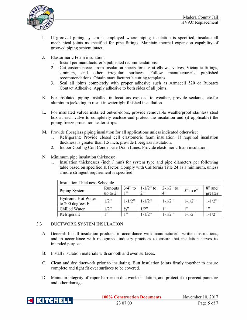
Madera County Jail HVAC Replacement
1.
100% Construction Documents November 10, 201723 07 00 Page 5 of 7
I. If grooved piping system is employed where piping insulation is specified, insulate all mechanical joints as specified for pipe fittings. Maintain thermal expansion capability of grooved piping system intact.
J. Elastormeric Foam insulation:1. Install per manufacturer’s published recommendations.2. Cut custom pieces from insulation sheets for use at elbows, valves, Victaulic fittings,
strainers, and other irregular surfaces. Follow manufacturer’s published recommendations. Obtain manufacturer’s cutting templates.
3. Seal all joints completely with proper adhesive such as Armacell 520 or Rubatex Contact Adhesive. Apply adhesive to both sides of all joints.
K. For insulated piping installed in locations exposed to weather, provide sealants, etc.for aluminum jacketing to result in watertight finished installation.
L. For insulated valves installed out-of-doors, provide removable weatherproof stainless steel box at each valve to completely enclose and protect the insulation and (if applicable) the piping freeze protection heater strips.
M. Provide fiberglass piping insulation for all applications unless indicated otherwise:1. Refrigerant: Provide closed cell elastomeric foam insulation. If required insulation
thickness is greater than 1.5 inch, provide fiberglass insulation.2. Indoor Cooling Coil Condensate Drain Lines: Provide elastomeric foam insulation.
N. Minimum pipe insulation thickness:1. Insulation thicknesses (inch / mm) for system type and pipe diameters per following
table based on specified K factor. Comply with California Title 24 as a minimum, unless a more stringent requirement is specified.
Insulation Thickness Schedule
Piping System Runouts up to 2”
3/4” to 1”
1-1/2” to 2”
2-1/2” to 4” 5” to 6” 8” and
greaterHydronic Hot Waterto 200 degrees F 1/2” 1-1/2” 1-1/2” 1-1/2” 1-1/2” 1-1/2”
Chilled Water 1/2” ½” 1/2” 1” 1” 1”Refrigerant 1” 1” 1-1/2” 1-1/2” 1-1/2” 1-1/2”
3.3 DUCTWORK SYSTEM INSULATION
A. General: Install insulation products in accordance with manufacturer’s written instructions, and in accordance with recognized industry practices to ensure that insulation serves its intended purpose.
B. Install insulation materials with smooth and even surfaces.
C. Clean and dry ductwork prior to insulating. Butt insulation joints firmly together to ensure complete and tight fit over surfaces to be covered.
D. Maintain integrity of vapor-barrier on ductwork insulation, and protect it to prevent puncture and other damage.

Madera County Jail HVAC Replacement
1.
100% Construction Documents November 10, 201723 07 00 Page 6 of 7
E. Extend ductwork insulation without interruption through walls, floors and similar ductwork penetrations, except at fire dampers, fire/smoke dampers, or where otherwise indicated.
F. Insulate all ductwork except for the following, unless otherwise indicated:1. Exhaust ductwork, unless within 25 feet of fan..2. Factory insulated or lined items such as terminal units, air supply chambers, etc.3. Conditioned air supply duct exposed in conditioned area served by that duct.4. 10 feet downstream of humidifiers.5. When code prohibits.
G. Application requirements:1. Ductwork Installed within Buildings: Insulate with minimum 1-1/2 inches thick
(installed thickness 1 inch), fiberglass duct wrap insulation with vapor barrier, unless otherwise specified.
2. Ductwork Installed out-of-doors (Including Ductwork within Architectural Screen or Enclosure):a. Insulate with 2-inch thick elastomeric foam insulation.b. Install per manufacturer’s published recommendations.c. Cut custom pieces from insulation sheets.d. Seal all joints completely with proper adhesive such as Armacell 520 or Rubatex
Contact Adhesive. Apply adhesive to both sides of all joints.e. Enclose within 0.016 inch aluminum jacket with Z-joint seams and butt straps.
Provide sealants, etc. to result in watertight finished installation.
3.4 EQUIPMENT INSULATION
A. General: Install equipment thermal insulation products in accordance with manufacturer’s written instructions, and in compliance with recognized industry practices to ensure that insulation serves intended purpose.
B. Install insulation materials with smooth and even surfaces and on clean and dry surfaces. Redo poorly fitted joints. Do not use mastic or joint sealer as filler for gapping joints and excessive voids resulting from poor workmanship.
C. Apply insulation using staggered joint method for both single and double layer construction, where feasible. Apply each layer of insulation separately.
D. Coat insulated surfaces with layer of insulating cement, troweled in workmanlike manner, leaving smooth continuous surface. Fill in scored block, seams, chipped edges and depressions, and cover over wire netting and joints with cement of sufficient thickness to remove surface irregularities.
E. Cover insulated surfaces with all-service jacketing neatly fitted and firmly secured. Lap seams at least 2 inches. Apply over vapor barrier where applicable.
F. Provide removable insulation sections to cover parts of equipment which must be opened periodically for maintenance; include metal vessel covers, fasteners, flanges, frames and accessories.
END OF SECTION 23 07 00

Madera County Jail HVAC Replacement
1.
100% Construction Documents November 10, 201723 07 00 Page 7 of 7
THIS PAGE LEFT BLANK

Madera County Jail HVAC Replacement
100% Construction Documents November 10, 2017
23 09 13 Page 1 of 6
SECTION 23 09 13 - INSTRUMENTATION FOR HVAC
PART 1 GENERAL
1.1 SUMMARY
A. Section Includes:1. Pressure Gauges.2. Pressure Gauge Taps.3. Stem Type Thermometers.4. Dial Thermometers.5. Thermometer Supports.6. Test Plugs.7. Static Pressure Gauges.8. Isolation Room Monitoring System.
B. Related Sections:1. Section 23 05 00 - Common Work Results for HVAC.2. Section 23 09 24 - Direct Digital Control System for HVAC.
1.2 REFERENCES
A. ASME B40.100 - Pressure Gauges and Gauge Attachments.
B. ASME MFC-3M - Measurement of Fluid Flow in Pipes Using Orifice, Nozzle and Venturi.
C. ASTM International:1. ASTM E1 - Specification for ASTM Liquid-in-Glass Thermometers.2. ASTM E77 - Standard Test Method for Inspection and Verification of Thermometers.
D. AWWA C700 - Cold-Water Meters - Displacement Type, Bronze Main Case.
E. ANSI/AWWA C701 - Cold Water Meters - Turbine Type for Customer Service.
F. AWWA C702 - Cold Water Meters - Compound Type.
G. ANSI/AWWA C706-96 - Direct-Reading Remote-Registration Systems for Cold-Water Meters.
H. AWWA M6 - Water Meters Selection, Installation, Testing and Maintenance.
I. FS-GG-G-76 - Gauges, Pressure and Vacuum, Dial Indicating (for Air, Steam, Oil, Water, Ammonia, Chloro-Fluorohydrocarbon Gases, and Compressed Gases).
J. ISA-SP3 - Flange–Mounted, Sharp-Edged Orifice Plates for Flow Measurement.
K. UL 393 (Ed. 8) - Indicating Pressure Gauges for Fire-Protection Service.
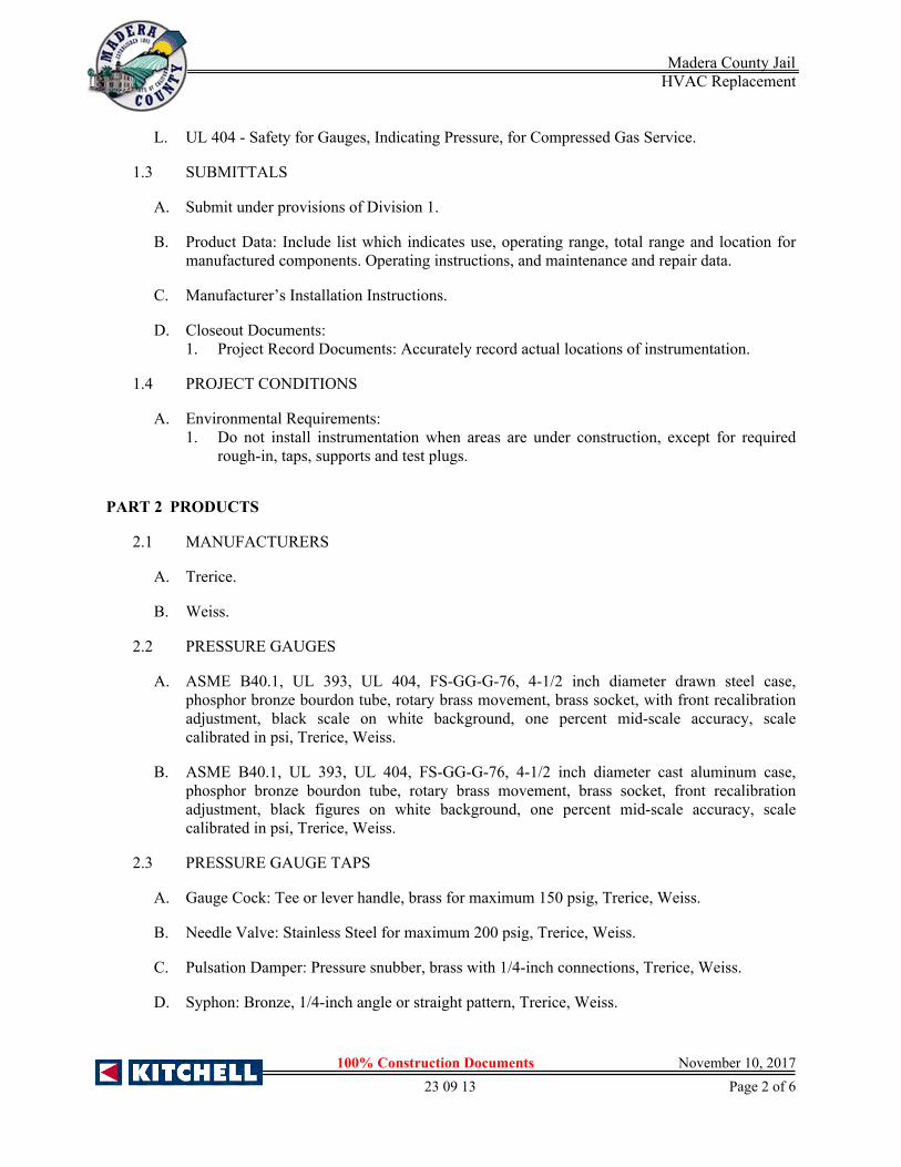
Madera County Jail HVAC Replacement
100% Construction Documents November 10, 2017
23 09 13 Page 2 of 6
L. UL 404 - Safety for Gauges, Indicating Pressure, for Compressed Gas Service.
1.3 SUBMITTALS
A. Submit under provisions of Division 1.
B. Product Data: Include list which indicates use, operating range, total range and location for manufactured components. Operating instructions, and maintenance and repair data.
C. Manufacturer’s Installation Instructions.
D. Closeout Documents:1. Project Record Documents: Accurately record actual locations of instrumentation.
1.4 PROJECT CONDITIONS
A. Environmental Requirements:1. Do not install instrumentation when areas are under construction, except for required
rough-in, taps, supports and test plugs.
PART 2 PRODUCTS
2.1 MANUFACTURERS
A. Trerice.
B. Weiss.
2.2 PRESSURE GAUGES
A. ASME B40.1, UL 393, UL 404, FS-GG-G-76, 4-1/2 inch diameter drawn steel case, phosphor bronze bourdon tube, rotary brass movement, brass socket, with front recalibration adjustment, black scale on white background, one percent mid-scale accuracy, scale calibrated in psi, Trerice, Weiss.
B. ASME B40.1, UL 393, UL 404, FS-GG-G-76, 4-1/2 inch diameter cast aluminum case, phosphor bronze bourdon tube, rotary brass movement, brass socket, front recalibration adjustment, black figures on white background, one percent mid-scale accuracy, scale calibrated in psi, Trerice, Weiss.
2.3 PRESSURE GAUGE TAPS
A. Gauge Cock: Tee or lever handle, brass for maximum 150 psig, Trerice, Weiss.
B. Needle Valve: Stainless Steel for maximum 200 psig, Trerice, Weiss.
C. Pulsation Damper: Pressure snubber, brass with 1/4-inch connections, Trerice, Weiss.
D. Syphon: Bronze, 1/4-inch angle or straight pattern, Trerice, Weiss.

Madera County Jail HVAC Replacement
100% Construction Documents November 10, 2017
23 09 13 Page 3 of 6
2.4 STEM TYPE THERMOMETERS
A. ASTM E1, 7-inch scale, red appearing mercury, lens front tube, cast aluminum case with enamel finish and clear glass or polycarbonate window, 3-1/2 inch brass stem, 2 percent of scale accuracy to ASTM E77 scale calibrated in degrees F, Trerice, Weiss.
B. ASTM E1, 7-inch scale, adjustable angle, red appearing mercury, lens front tube, cast aluminum case with enamel finish and clear glass window, 3-1/2 inch brass stem, cast aluminum adjustable joint with positive locking device, 2 percent of scale accuracy to ASTM E77, scale calibrated in degrees F, Trerice, Weiss.
2.5 DIAL THERMOMETERS
A. ASTM E1, 2-inch diameter dial in stainless steel case, bimetallic helix actuated with silicone fluid damping, white with black markings and black pointer hermetically sealed glass lens, stainless steel stem, one percent of full scale accuracy, calibrated in degrees F, Trerice, Weiss.
B. ASTM E1, 3-inch diameter dial in stainless steel case, adjustable angle with front recalibration, bimetallic helix actuated with silicone fluid damping, white with black markings and black pointer hermetically sealed glass lens, stainless steel stem, one percent of full scale accuracy, calibrated in degrees F.
C. ASTM E1, 2-1/2 inch diameter dial in stainless steel case, vapor or liquid actuated with brass or copper bulb, 5 feet minimum copper or bronze braided capillary, white with black markings and black pointer glass lens, 2 percent mid-scale accuracy, calibrated in degrees F.
2.6 THERMOMETER SUPPORTS
A. Socket: Brass separable sockets for thermometer stems with or without extensions as required, and with cap and chain, Trerice, Weiss.
B. Flange: 3-inch outside diameter reversible flange, designed to fasten to sheet metal air ducts, with brass perforated stem, Trerice, Weiss.
2.7 TEST PLUGS
A. Test Plug: 1/4-inch or 1/2-inch brass or stainless steel fitting and cap for receiving 1/8-inch outside diameter pressure or temperature probe with neoprene core for temperatures up to 200-degrees F, Nordel core for temperatures up to 350 degrees F, Viton core for temperatures up to 400-degrees F, Trerice, Weiss.
B. Test Kit: Carrying case, internally padded and fitted containing one 3 1/2-inch diameter pressure gauges, one gauge adapters with 1/8-inch probes, two 1 1/2-inch dial thermometers, Trerice, Weiss.
2.8 STATIC PRESSURE GAUGES
A. 3-1/2 inch diameter dial in metal case, diaphragm actuated, black figures on white background, front recalibration adjustment with tubing, static pressure tips, Trerice, Weiss.

Madera County Jail HVAC Replacement
100% Construction Documents November 10, 2017
23 09 13 Page 4 of 6
2.9 ISOLATION ROOM MONITORING SYSTEM
A. Monitoring System:1. Space pressure monitoring system must be capable of continuous bi-directional
measurement of air pressure in inches of water column (wc). System must initiate an alarm at the Nurse’s Station ventilation status panel (VSP) when a pressure differential of 0.001-inch wc occurs at any of the monitored areas.a. Pressure monitor must have a minimum capability of monitoring pressure
differential of 0.001-inch wc.b. Monitor must have a pressure range of -0.1-inch to 0.1-inch wc with full scale
range adjustable to +0.001, +0.005-inch, +0.010-inch, +0.10.c. Alarm contact output.d. Self powered 4 to 20-ma output to display pressure of velocity at the corridor and
sub-utility room alarm panels.e. Accuracy: +2-percent of reading.f. Transformer.g. Adjustable time delay for door openings, 0 to 60-seconds, set initial setting at 15-
seconds.h. Pressure monitor must be Iso-Tek SPM-5000 series.i. Provide 14-gauge type 304 stainless steel enclosure with hinged lockable access
door set recessed in sub-utility room. Coordinate exact location in field to miss other devices. Display monitor for isolation room noted below, placement in this enclosure must be located as required for maximum visibility thru window from isolation room.
j. Furnish all wiring and conduit with required interfacing at Ventilation Status Panel (VSP).
2. Room display monitor must be a digital display module with indication lights.a. Digital display module must have a minimum of 3 digits with provision for minus
indication.b. Indication lights must have red and green alarm/safe light.c. Display monitor must be Red Lion Model LPPI.d. Location:e. Adjacent to corridor door to display pressure differential between corridor and
isolation room.f. In sub-utility room to display pressure differential between isolation room and
corridor. Locate in same enclosure as pressure monitoring module with face of display set flush in access door.
g. Calibration Tool: One required. Iso-Tek SPM-7000.
PART 3 EXECUTION
3.1 INSTALLATION
A. Install in accordance with manufacturer’s instructions.
B. Install positive displacement meters with isolating valves on inlet and outlet to AWWA M6. Provide full line size valved bypass with globe valve for liquid service meters.

Madera County Jail HVAC Replacement
100% Construction Documents November 10, 2017
23 09 13 Page 5 of 6
C. Provide one pressure gauge per pump, installing taps before strainers and on suction and discharge of pump. Pipe to gauge.
D. Install pressure gauges with pulsation dampers. Provide gauge cock or needle valve to isolate each gauge.
E. Install thermometers in piping systems in sockets in short couplings. Enlarge pipes smaller than 2-1/2 inch for installation of thermometer sockets.
F. Install thermometers in air duct systems on flanges.
G. Install thermometer sockets adjacent to controls system thermostat, transmitter, or sensor sockets. Where thermometers are provided on local panels, duct or pipe mounted Thermometers are not required.
H. Locate duct mounted thermometers minimum 10 feet downstream of mixing dampers, coils, or other devices causing air turbulence.
I. Coil and conceal excess capillary on remote element instruments.
J. Provide instruments with scale ranges selected according to service with largest appropriate scale.
K. Install gauges and thermometers in locations where they are easily read from normal operating level.
L. Locate test plugs adjacent to control device sockets and where indicated.
3.2 SCHEDULES
A. Positive Displacement Meter Schedule
LOCATION SCALE RANGEDomestic cold water 0 to 150 PSI
B. Pressure Gauge Schedule
LOCATION SCALE RANGEPumps 0 to 200 PSIExpansion tanks 0 to 200 PSISprinkler system 0 to 200 PSIPressure reducing valves 0 to 200 PSIBackflow preventers 0 to 200 PSI
C. Stem Type Thermometer Schedule
LOCATION SCALE RANGEDomestic hot water supply and recirculation 30 to 180 degrees

Madera County Jail HVAC Replacement
100% Construction Documents November 10, 2017
23 09 13 Page 6 of 6
D. Dial Thermometer Schedule
LOCATION SCALE RANGEEach supply air zone 0 to 160 degreesOutside air 0 to 120 degreesReturn air 0 to 100 degreesMixed air 0 to 100 degrees
E. Static Pressure and Filter Gauge Schedule
LOCATION SCALE RANGEBuilt up filter banks 0 to 5 inchUnitary filter sections 0 to 5 inchSupply fan discharge 0 to 5 inchBuilding static 0 to 5 inch
END OF SECTION 23 09 13

Madera County Jail HVAC Replacement
100% Construction Documents November 10, 201723 09 24 Page 1 of 44
SECTION 23 09 24 - DIRECT DIGITAL CONTROL SYSTEM
PART 1 GENERAL
1.1 SUMMARY
A. Section Includes:1. Control Equipment.2. Software.
B. Related Sections:1. Section 23 05 00 - Common Work Results for HVAC.2. Section 23 05 13 - Common Motor Requirements for HVAC.3. Section 23 05 29 - Hangers and Supports for HVAC.4. Section 23 05 93 - Testing, Adjusting and Balancing.5. Section 23 21 13 - Hydronic Piping6. Section 23 21 23 - Hydronic Pumps.7. Section 23 31 00 - HVAC Ducts and Casings.8. Section 23 33 00 - Air Duct Accessories.9. Section 23 34 00 - HVAC Fans.10. Section 23 36 00 – Air Terminal Units.11. Section 23 52 16 - Condensing Boilers.12. Section 23 64 16 - Centrifugal Water Chillers.13. Section 23 65 00 - Cooling Towers.14. Section 23 73 23 - Custom Indoor Air Handling Units.15. Section 26 05 19 - Low-Voltage Electrical Power Conductors and Cables.
1.2 REFERENCES
C. ASHRAE 85 - Automatic Control Terminology for Heating, Ventilating, Air Conditioning.
D. ASME MC85.1 - Terminology for Automatic Control.
E. NEMA EMC1 - Energy Management Systems Definitions.
F. U.L. Listing for electric cabinets/controls.
1.3 WORK INCLUDED
A. Furnish a totally native BACnet-based system. The operator’s workstation, all building controllers, application controllers, and all input/output devices shall communicate using the protocols and network standards as defined by ANSI/ASHRAE Standard 135–2008, BACnet. No gateways shall be used for communication to controllers installed under this section.
B. Provide all necessary BACnet-compliant hardware and software to meet the system’s functional specifications. Provide Protocol Implementation Conformance Statement (PICS) for Windows-based control software and every controller in system, including unitary
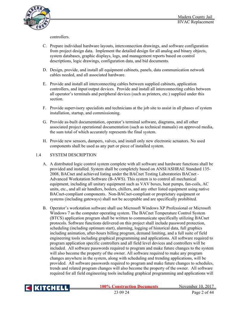
Madera County Jail HVAC Replacement
100% Construction Documents November 10, 201723 09 24 Page 2 of 44
controllers.
C. Prepare individual hardware layouts, interconnection drawings, and software configuration from project design data. Implement the detailed design for all analog and binary objects, system databases, graphic displays, logs, and management reports based on control descriptions, logic drawings, configuration data, and bid documents.
D. Design, provide, and install all equipment cabinets, panels, data communication network cables needed, and all associated hardware.
E. Provide and install all interconnecting cables between supplied cabinets, application controllers, and input/output devices. Provide and install all interconnecting cables between all operator’s terminals and peripheral devices (such as printers, etc.) supplied under this section.
F. Provide supervisory specialists and technicians at the job site to assist in all phases of system installation, startup, and commissioning.
G. Provide as-built documentation, operator’s terminal software, diagrams, and all other associated project operational documentation (such as technical manuals) on approved media, the sum total of which accurately represents the final system.
H. Provide new sensors, dampers, valves, and install only new electronic actuators. No used components shall be used as any part or piece of installed system.
1.4 SYSTEM DESCRIPTION
A. A distributed logic control system complete with all software and hardware functions shall be provided and installed. System shall be completely based on ANSI/ASHRAE Standard 135-2008, BACnet and achieved listing under the BACnet Testing Laboratories BACnet - Advanced Workstation Software (B-AWS). This system is to control all mechanical equipment, including all unitary equipment such as VAV boxes, heat pumps, fan-coils, AC units, etc., and all air handlers, boilers, chillers, and any other listed equipment using native BACnet-compliant components. Non-BACnet-compliant or proprietary equipment or systems (including gateways) shall not be acceptable and are specifically prohibited.
B. Operator’s workstation software shall use Microsoft Windows XP Professional or Microsoft Windows 7 as the computer operating system. The BACnet Temperature Control System (BTCS) application program shall be written to communicate specifically utilizing BACnet protocols. Software functions delivered on this project shall include password protection, scheduling (including optimum start), alarming, logging of historical data, full graphics including animation, after-hours billing program, demand limiting, and a full suite of field engineering tools including graphical programming and applications. All software required to program application specific controllers and all field level devices and controllers will be included. All software passwords required to program and make future changes to the system will also become the property of the owner. All software required to make any program changes anywhere in the system, along with scheduling and trending applications, will be provided. All software passwords required to program and make future changes to schedules, trends and related program changes will also become the property of the owner. All software required for all field engineering tools including graphical programming and applications will
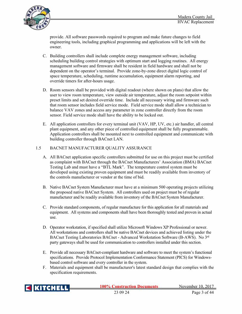
Madera County Jail HVAC Replacement
100% Construction Documents November 10, 201723 09 24 Page 3 of 44
provide. All software passwords required to program and make future changes to field engineering tools, including graphical programming and applications will be left with the owner.
C. Building controllers shall include complete energy management software, including scheduling building control strategies with optimum start and logging routines. All energy management software and firmware shall be resident in field hardware and shall not be dependent on the operator’s terminal. Provide zone-by-zone direct digital logic control of space temperature, scheduling, runtime accumulation, equipment alarm reporting, and override timers for after-hours usage.
D. Room sensors shall be provided with digital readout (where shown on plans) that allow the user to view room temperature, view outside air temperature, adjust the room setpoint within preset limits and set desired override time. Include all necessary wiring and firmware such that room sensor includes field service mode. Field service mode shall allow a technician to balance VAV zones and access any parameter in zone controller directly from the room sensor. Field service mode shall have the ability to be locked out.
E. All application controllers for every terminal unit (VAV, HP, UV, etc.) air handler, all central plant equipment, and any other piece of controlled equipment shall be fully programmable. Application controllers shall be mounted next to controlled equipment and communicate with building controller through BACnet LAN.
1.5 BACNET MANUFACTURER QUALITY ASSURANCE
A. All BACnet application specific controllers submitted for use on this project must be certified as complaint with BACnet through the BACnet Manufacturers’ Association (BMA) BACnet Testing Lab and must have a “BTL Mark”. The temperature control system must be developed using existing proven equipment and must be readily available from inventory of the controls manufacturer or vendor at the time of bid.
B. Native BACnet System Manufacturer must have at a minimum 500 operating projects utilizing the proposed native BACnet System. All controllers used on project must be of regular manufacturer and be readily available from inventory of the BACnet System Manufacturer.
C. Provide standard components, of regular manufacture for this application for all materials and equipment. All systems and components shall have been thoroughly tested and proven in actual use.
D. Operator workstation, if specified shall utilize Microsoft Windows XP Professional or newer. All workstations and controllers shall be native BACnet devices and achieved listing under the BACnet Testing Laboratories BACnet - Advanced Workstation Software (B-AWS). No 3rd party gateways shall be used for communication to controllers installed under this section.
E. Provide all necessary BACnet-compliant hardware and software to meet the system’s functional specifications. Provide Protocol Implementation Conformance Statement (PICS) for Windows-based control software and every controller in the system.
F. Materials and equipment shall be manufacturer's latest standard design that complies with the specification requirements.

Madera County Jail HVAC Replacement
100% Construction Documents November 10, 201723 09 24 Page 4 of 44
G. All BAS peer-to-peer network controllers, central system controllers and local user displays shall be UL Listed under Standard UL 916, category PAZX.
H. All electronic equipment shall conform to the requirements of FCC Regulation, Part 15, Governing Radio Frequency Electromagnetic Interference and be so labeled.
1.6 BACNET SYSTEM CONTRACTOR QUALITY ASSURANCE
A. Responsibility: All work described in this section shall be engineered, installed, wired, circuit tested calibrated and programmed by regularly employed control system engineers and electricians and technicians of the authorized temperature control system factory representative or branch office of the listed approved manufacturer. System Engineering, Programming and Installation shall not be subcontracted. The supplier of the BACnet Temperature Control and Energy Management System shall be responsible for inspection and Quality Assurance (QA) for all materials and workmanship furnished by him. Contractor must have a valid C-10 and C-20 license to bid this project.
B. The Building Automation System (BAS) system shall be designed, installed, started up, and serviced by manufacturer authorized and trained personnel. System provider shall have an in-place support facility within 2 hours response time of the site with technical staff, spare parts inventory, and necessary test and diagnostic equipment.
C. Component Testing and Availability: Maximum reliability shall be achieved through extensive use of high-quality, pre-tested components. The manufacturer prior to shipment shall individually test each and every controller, sensor, and all other DDC components. EMS System Contractor or Manufacturer must certify that any DDC part can be replaced within 5 working days.
D. Unacceptable Bids: Bids by wholesalers, parts distributors, contractors or franchised dealers or any firm whose principal business is not that of installing automatic temperature control systems shall not be acceptable.
E. Experience: BACnet System Contractor (BSC) shall have been in business and licensed by the State of California for a minimum of five continuous years prior to this project bid. BSC must have been a factory authorized representative for a minimum of five years of the contractors proposed manufacturer’s products and systems.
F. BSC must have performed, from an office not more than 100 miles from project site at least 25 projects, each of which included the installation of not less than 250 hardware I/O points, using the contractors proposed manufacturer’s products and systems. Five of the 25 projects must have included the installation of not less than 1,500 hardware I/O points using the contractors proposed manufacturer’s products and systems.
G. BSC shall have on staff a full time Mechanical Engineer that is a licensed Professional Engineer by the State of California, having not less than four years’ experience with the contractors proposed manufacturer’s products and systems.

Madera County Jail HVAC Replacement
100% Construction Documents November 10, 201723 09 24 Page 5 of 44
H. BSC shall have on staff a LEED Accredited Professional, having not less than three years’ experience with the contractors proposed manufacturer’s products and systems.
I. BSC shall have on staff a full time Applications Engineer and Control System Programmer, having not less than three years’ experience with the contractors proposed manufacturer’s products and systems.
J. BSC shall have on staff a minimum of three full time control technicians, Senior control technician shall have not less than three years’ experience, junior technicians shall have not less than one years’ experience with the contractors proposed manufacturer’s products and systems.
K. BSC shall have a full time service department with service available 24 hours a day, seven days a week. Service department will have been established for a minimum of five years and be staffed with factory trained and authorized service technicians capable of servicing all aspects of the control systems depicted on these plans.
L. Service department shall have on staff a full time control system telephone support technician available during normal business hours dedicated to taking customer support calls and having the ability to call the project site and perform on-line diagnostics.
M. BSC shall assign an in-house project manager to provide a detailed project design and installation schedule with time markings and details for hardware items and software development phases. Schedule shall show all the target dates for transmission of project information and documents and shall indicate timing and dates for system installation, debugging, and commissioning.
N. BSC shall field verify existing controls that are to be reconnected to control system prior to design, submittal, and installation of work of this section. Notify Architect immediately of any discrepancies between field conditions and Work shown in the Contract Documents.
1.7 REFERENCE STANDARDS
A. The latest edition of the following standards and codes in effect and amended as of supplier's proposal date, and any applicable subsections thereof, shall govern design and selection of equipment and material supplied:
1. American Society of Heating, Refrigerating and Air Conditioning Engineers (ASHRAE).
2. ANSI/ASHRAE Standard 135-2008, BACnet.
3. Uniform Building Code (UBC), including local amendments.
4. UL 916 Underwriters Laboratories Standard for Energy Management Equipment. Canada and the US.
5. National Electrical Code (NEC).
6. FCC Part 15, Subpart J, Class A.

Madera County Jail HVAC Replacement
100% Construction Documents November 10, 201723 09 24 Page 6 of 44
7. EMC Directive 89/336/EEC (European CE Mark).
8. UL-864 UUKL listing for Smoke Controls for any equipment used in smoke control sequences.
B. City, county, state, and federal regulations and codes in effect as of contract date.
C. Except as otherwise indicated, the system supplier shall secure and pay for all permits, inspections, and certifications required for his work, and arrange for necessary approvals by the governing authorities.
1.8 SUBMITTALS
A. Drawings
1. The system supplier shall submit engineered drawings, control sequence, and bill of materials for approval.
2. Drawings shall be submitted in the following standard sizes: 11” x 17” (ANSI B).
3. Eight complete sets (copies) of submittal drawings shall be provided.
4. Drawings shall be available on CD-ROM.
B. System Documentation
Include the following in submittal package:
1. System configuration diagrams in simplified block format.
2. All input/output object listings and an alarm point summary listing.
3. Electrical drawings that show all system internal and external connection points, terminal block layouts, and terminal identification.
4. Complete bill of materials, sequence of operations, valve schedule and complete system BACnet controller address list.
5. Manufacturer's instructions and drawings for installation, maintenance, and operation of all purchased items.
6. Overall system operation and maintenance instructions—including preventive maintenance and troubleshooting instructions.
7. For all system elements—operator’s workstation(s), building controller(s), application controllers, routers, and repeaters—provide BACnet Protocol Implementation Conformance Statements (PICS) as per ANSI/ASHRAE Standard 135-2008.
8. Provide complete description and documentation of any proprietary (non-BACnet) services and/or objects used in the system.
9. A list of all functions available and a sample of function block programming that shall be

Madera County Jail HVAC Replacement
100% Construction Documents November 10, 201723 09 24 Page 7 of 44
part of delivered system.
10. Upon completion of the work, provide a set of ‘record drawings’ including manufactures descriptive literature, operating instructions and maintenance and repair data all in accordance with the requirements of the general mechanical specification section. Provide electronic copies of all control system as-built AutoCAD drawings.
C. Project Management
1. The vendor shall provide a detailed project design and installation schedule with time markings and details for hardware items and software development phases. Schedule shall show all the target dates for transmission of project information and documents, and shall indicate timing and dates for system installation, debugging, and commissioning.
1.9 WARRANTY
A. Warranty shall cover all costs for parts, labor, associated travel, and expenses for a period of one year from completion of system acceptance.
B. Hardware and software personnel supporting this warranty agreement shall provide on-site or off-site service in a timely manner after failure notification to the vendor. The maximum acceptable response time to provide this service at the site shall be 24 hours, Monday through Friday and 48 hours on Saturday and Sunday.
C. This warranty shall apply equally to both hardware and software.
1.10 RELATED WORK IN OTHER SECTIONS
A. Refer to Division 0 and Division 1 for related contractual requirements.
B. Refer to Section 23 for General Mechanical Provisions.
C. Refer to Section 26 for General Electrical Provisions.
PART 2 PRODUCTS
2.1 MANUFACTURERS
A. Alerton.
B. APPROVE EQUAL BY COUNTY.
2.2 OPERATOR’S WORKSTATION - EXISTING
A. General structure of workstation interaction shall be a standard client/server relationship. Server shall be used to archive data and store system database. Clients shall access server for all archived data. Each client shall include flexibility to access graphics from server or local drive. Server shall support a minimum of 50 simultaneous clients.

Madera County Jail HVAC Replacement
100% Construction Documents November 10, 201723 09 24 Page 8 of 44
B. BACnet Conformance
1. Operator workstation shall be approved by the BTL as meeting the BACnet Advanced Work Station (AWS) requirements.
2. Please refer to Section 22.2, BACnet Functional Groups, in the BACnet standard, for a complete list of the services that must be directly supported to provide each of the functional groups listed above. All proprietary services, if used in the system, shall be thoroughly documented and provided as part of the submittal data. All necessary tools shall be supplied for working with proprietary information.
3. Standard BACnet object types accessed by the AWS shall include as a minimum: Analog Value, Analog Input, Analog Output, Binary Value, Binary Input, Binary Output, Calendar, Device, Event Enrollment, File, Notification Class, Program, and Schedule object types. All proprietary object types, if used in the system, shall be thoroughly documented and provided as part of the submittal data. All necessary tools shall be supplied for working with proprietary information.
4. The AWS shall comply with Annex J of the BACnet specification for IP connections. Must support remote connection to server using a thick client application. This device shall use Ethernet to connect to the IP internetwork, while using the same Ethernet LAN for non-IP communications to other BACnet devices on the LAN. Must support interoperability on wide area networks (WANs) and campus area networks (CANs). AWS shall support Foreign Device Registration to allow temporary workstation connection to IP network.
C. Data Displays
1. Data displays shall render all data associated with project as called out on drawings and/or object type list supplied. Graphic files shall be created using digital, full color photographs of system installation, AutoCAD or Visio drawing files of field installation drawings, and wiring diagrams from as-built drawings.
2. Data displays shall render all data using iconic graphic representations of all mechanical equipment. System shall be capable of displaying graphic file, text, and dynamic object data together on each display and shall include animation. Information shall be labeled with descriptors and shall be shown with the appropriate engineering units. All information on any display shall be dynamically updated without any action by the user.
3. Data display frame shall allow user to change all field-resident AWS functions associated with the project, such as set points, weekly schedules, exception schedules, etc., from any screen, no matter if that screen shows all text or a complete graphic display. This shall be done without any reference to object addresses or other numeric/mnemonic indications.
4. Analog objects shall be displayed with operator modifiable units. Analog input objects may also be displayed as individual graphic items on the display screen as an overlay to the system graphic.

Madera County Jail HVAC Replacement
100% Construction Documents November 10, 201723 09 24 Page 9 of 44
5. All displays and programming shall be generated and customized by the local use energy management and control system (EMCS) supplier and installer. Systems requiring factory development of graphics or programming of DDC logic are specifically prohibited.
6. AWS shall be supplied with a library of standard graphics, which may be used unaltered or modified by the operator. AWS shall include a library of equipment graphic components to assemble custom graphics. Systems that do not allow customization or creation of new graphic objects by the operator (or with third-party software) shall not be allowed.
7. Data display frame shall include customizable and persistent tree navigation for building, equipment and system diagnostic centric display organization.
8. Each display may be protected from viewing unless operator credentials have the appropriate access level. An access level may be assigned to each display and system object. The menu label shall not appear on the graphic if the operator does not have the appropriate security level.
9. Data displays shall have the ability to link to content outside of the EMCS system. Such content shall include, but is not limited to launching external files in their native applications (for example, a Microsoft Word document) and launching a web browser resolving to a specified web address.
10. The AWS shall have the ability to support 20 concurrent web clients.
11. Data displays shall support:
a. Graphic items with custom geometry that offer both color gradient shading and variable opacity in scale to system variables and range set points.
b. Clear and custom geometry navigation buttons to provide intuitive navigation.
c. Graphic files in JPG, PNG, and GIF file types.
d. Viewing of 1,024 system data points in a single screen.
D. Password Protection
1. Provide security system that prevents unauthorized use unless operator is logged on. Access shall be limited to operator’s assigned functions when user is logged on. This includes displays as outlined above.
2. AWS shall provide security for a minimum of 200 users. Each user shall have an individual User ID, User Name, and Password. Entries are alphanumeric characters only and are case sensitive (except for User ID). User ID shall be 0–8 characters, User Name shall be 0–29 characters, and Password shall be 4–8 characters long.
3. Each user shall be allowed individual assignment of only those control functions, menu items, and user-specific system start display, as well as restricted access to discrete BACnet devices to which that user requires access.

Madera County Jail HVAC Replacement
100% Construction Documents November 10, 201723 09 24 Page 10 of 44
4. All passwords, user names, and access assignments shall be adjustable online at the operator’s terminal.
5. Users shall also have a set access level, which defines access to displays and individual objects the user may control. System shall include 10 separate and distinct access levels for assignment to users.
6. The system shall include an Auto Logout feature that shall automatically logout user when there has been no keyboard or mouse activity for a set period of time. Time period shall be adjustable by system administrator. Auto Logout may be enabled and disabled by system administrator. Operator terminal shall display message on screen that user is logged out after Auto Logout occurs.
7. The system shall permit the assignment of an effective date range, as well as an effective time of day, that the User IDs are permitted to authenticate.
E. Operator Activity Log
1. An Operator Activity Log that tracks all operator changes and activities shall be included with AWS. System shall track what is changed in the system, who performed this change, date and time of system activity, and value of the change before and after operator activity. Operator shall be able to display all activity, sort the changes by user and also by operation. Operator shall be able to print the Operator Activity Log display.
2. Log shall be gathered and archived to a hard drive on AWS as needed. Operator shall be able to export data for display and sorting in a spreadsheet.
F. Scheduling
1. AWS and web client shall show all information in easy-to-read daily format including calendar of this month and next. All schedules shall show actual ON/OFF times for day based on scheduling priority. Priority for scheduling shall be events, holidays and daily, with events being the highest.
2. Holiday and special event schedules shall display data in calendar format. Operator shall be able to schedule holidays and special events directly from these calendars.
3. Operator shall be able to change all information for a given weekly or exception schedule if logged on with the appropriate access privileges.
4. AWS shall include a Schedule Wizard for set up of schedules. Wizard shall walk user through all steps necessary for schedule generation. Wizard shall have its own pull-down selection for startup or may be started by right-clicking on value displayed on graphic and then selecting Schedule.
5. Scheduling shall include optimum start based on outside air temperature, current heating/cooling set-points, indoor temperature and history of previous starts. Each and every individual zone shall have optimum start time independently calculated based on all parameters listed. User shall input schedules to set time that occupied setpoint is to be attained. Optimum start feature shall calculate the startup time needed to match zone
Madera County Jail HVAC Replacement
100% Construction Documents November 10, 201723 09 24 Page 11 of 44
temperature to setpoint. User shall be able to set a limit for the maximum startup time allowed.
6. Schedule list shall show all schedules currently defined. This list shall include all standard, holiday and event schedules. In addition, user shall be able to select a list that shows all scheduled points and zones.
7. Display of all three schedules must show all ON times for standard, holiday and event schedules in different colors on a given day. In addition, OFF times for each must also be shown in additional colors. User shall be able to select from standard calendar what days are to be scheduled and same display shall show all points and zones affected. User shall be able to set time for one day and select all days of the week that shall be affected as a recurrence of that same schedule for that given day.
8. Any displayed data that is changeable by the operator may be selected using the right mouse button and the schedule shall then be selectable on the screen. Selection of the schedule using this method shall allow the viewing of the assigned schedule allow the point to be scheduled.
9. Schedule editor shall support drag-n-drop events and holidays onto the schedule calendar.
10. Schedule editor shall support drag-n-drop events default to a two-hour period, which can then be adjusted by the user.
11. Schedule editor shall support drag-n-drop holidays default for OFF all day and can be edited for multiple-day holidays.
12. Schedule editor shall support the view of affected zones when adding or editing timed events of a schedule.
G. Alarm Indication and Handling.
1. AWS shall provide visual, printed, and email means of alarm indication. Printout of alarms shall be sent to the assigned terminal and port. Alarm notification can be filtered based on the User ID’s authorization level.
2. Web client shall display a persistent alarm state for the system regardless of the data view including points in alarm but not acknowledged, and points that have gone into alarm and returned to normal without being acknowledged.
3. Alarm History shall provide log of alarm messages. Alarm log shall be archived to the hard disk of the AWS. Each entry shall include a description of the event-initiating object generating the alarm. Description shall be an alarm message of at least 256 characters in length. Entry shall include time and date of alarm occurrence, time and date of object state return to normal, time and date of alarm acknowledgment, and identification of operator acknowledging alarm.
4. Alarm messages shall be in user-definable text (English or other specified language) and shall be delivered either to the operator’s terminal, client or through remote communication using email (Authenticated SMTP supported).

Madera County Jail HVAC Replacement
100% Construction Documents November 10, 201723 09 24 Page 12 of 44
5. AWS shall include an Alarm Wizard for set up of alarms. Wizard shall walk user through all steps necessary for alarm generation. Wizard shall have its own pull-down selection for startup or may be started by right-clicking on value displayed on graphic and then selecting alarm setup.
6. AWS shall support color-coded indication of current alarms as follows:
a. Red indicator shows number of active alarms that have not been acknowledged.
b. Yellow indicator shows number of alarms that are still active but have been acknowledged.
c. Blue indicator shows number of alarms that have returned to normal but have not been acknowledged.
d. Color-coded indicators, when selected by the user, navigate to a pre-filtered view of alarm history.
e. Alarm history can be filtered by color-coded indicator states.
7. Alarm annunciation includes navigation link to a user-selected display or URL.
8. User can silence audible annunciation for the current session.
9. User can disable auto-refresh of alarm annunciation for current session.
10. Any displayed data that is changeable by the operator may be selected using the right mouse button and the alarm shall then be selectable on the screen. Selection of the alarm using this method shall allow the viewing of the alarm history or allow the creation of a new alarm.
H. Trendlog Information
1. AWS shall periodically gather historically recorded data stored in the building controllers and store the information in the system database. Stored records shall be appended with new sample data, allowing records to be accumulated. Systems that write over stored records shall not be allowed unless limited file size is specified. System database shall be capable of storing up to 50 million records before needing to archive data. Samples may be viewed at the web client. Operator shall be able to view all trended records, both stored and archived. All trendlog records shall be displayed in standard engineering units.
2. AWS shall be capable of trending on an interval determined by a polling rate, or change-of-value.
3. AWS shall be able to change trendlog setup information. This includes the information to be logged as well as the interval at which it is to be logged. All operations shall be password protected. Viewing may be accessed directly from any and all graphics on which a trended object is displayed.
4. AWS shall include a Trendlog Wizard for setup of logs. Wizard shall walk user through all necessary steps. Wizard shall have its own pull-down selection for startup, or may be started by right-clicking on value displayed on graphic, and then selecting Trendlogs

Madera County Jail HVAC Replacement
100% Construction Documents November 10, 201723 09 24 Page 13 of 44
from the displayed menu.
5. AWS shall be capable of using Microsoft SQL as the system database.
6. Any displayed data that is changeable by the operator may be selected using the right mouse button and the trendlog shall then be selectable on the screen. Selection of the trendlog using this method shall allow the viewing of the trendlog view.
7. Trendlog viewer shall provide:
a. Software that is capable of graphing the trend-logged object data shall be included.
b. Access and ability to create, edit and view are restricted to users by user account credentials
c. Specific and repeatable URL defines the trendlog(s) that comprise the view.
d. Call out of trendlog value at intersection of trend line and mouse-over vertical axis.
e. Trendlog and companion logs can be configured to display on one of two independent vertical scales.
f. Click zoom for control of data set viewed along either graph axis.
g. User-specifiable start and end dates as well as a fast scroll features that supports click zoom of macro scale view of the data for quickly finding data set based on visual signature.
h. User export of the viewed data set to MS Excel.
i. Web browser-based help.
j. Optional min/max ranges (Upper Control Limits, Lower Control Limits) for each value.
I. Energy Log Information
1. AWS shall be capable of periodically gathering energy log data stored in the field equipment and archive the information. Archive files shall be appended with new data, allowing data to be accumulated. Systems that write over archived data shall not be allowed unless limited file size is specified. Display all energy log information in standard engineering units.
2. All data shall be stored in database file format for direct use by third-party programs. Operation of system shall stay completely online during all graphing operations.
3. AWS operator shall be able to change the energy log setup information as well. This includes the meters to be logged, meter pulse value, and the type of energy units to be logged. All meters monitored by the system may be logged. System shall support using flow and temperature sensors for BTU monitoring.
4. AWS shall display archived data in tabular format form for both consumption and peak

Madera County Jail HVAC Replacement
100% Construction Documents November 10, 201723 09 24 Page 14 of 44
values. Data shall be shown in hourly, daily, weekly, monthly and yearly formats. In each format, the user shall be able to select a specific period of data to view.
J. Demand Limiting
1. AWS shall include demand-limiting program that includes two types of load shedding. One type of load shedding shall shed/restore equipment in binary fashion based on energy usage when compared to shed and restore settings. The other type of shedding shall adjust operator-selected control set points in an analog fashion based on energy usage when compared to shed and restore settings. Shedding may be implemented independently on each and every zone or piece of equipment connected to system.
2. Binary shedding shall include minimum of five (5) priority levels of equipment shedding. All loads in a given priority level shall be shed before any loads in a higher priority level are shed. Load shedding within a given priority level shall include two methods. In one, the loads shall be shed/restored in a “first off-first on” mode, and in the other the loads are just shed/restored in a “first off-last on” (linear) fashion.
3. Analog shed program shall generate a ramp that is independently used by each individual zone or individual control algorithm to raise the appropriate cooling setting and lower appropriate heating setting to reduce energy usage.
4. AWS shall be able to display the status of each and every load-shed program. Status of each load assigned to an individual shed program shall be displayed along with English description of each load.
K. Tenant Activity
1. AWS shall include program that monitors after-hours overrides by tenants, logs that data, and generates a bill based on usage and rate charged for each tenant space. Tenant Activity program shall be able to assign multiple zones, from a list of every zone connected to system, to a particular tenant. Every zone is monitored for after-hours override usage and that data logged in AWS. Operator may then generate a bill based on the usage for each tenant and the rate charged for any overtime use.
2. Configuration shall include entry of the following information for use in logging and billing:
a. Tenant’s contact name and address
b. One or multiple tenant zones that make up a total tenant space, including a separate billing rate for each separate zone
c. Minimum and maximum values an event duration and event limit
d. Property management information
e. Overall billing rate
f. Seasonal adjustments or surcharge to billing rate

Madera County Jail HVAC Replacement
100% Construction Documents November 10, 201723 09 24 Page 15 of 44
g. Billing notification type including, but not limited to printer, file and email
h. Billing form template
3. Logging shall include recording the following information for each and every tenant event:
a. Zone description
b. Time the event begins
c. Total override time
d. Limits shall be applied to override time
4. A tenant bill shall be generated for a specific period using all the entered configuration data and the logged data. User with appropriate security level shall be able to view and override billing information. User shall be able to select a billing period to view and be able to delete events from billing and edit a selected tenant activity event’s override time.
L. Reports
1. AWS shall be capable of periodically producing reports of trendlogs, alarm history, tenant activities, device summary, energy logs, and override points. The frequency, content, and delivery are to be user adjustable.
2. All reports shall be capable of being delivered in multiple formats including text- and comma-separated value (CSV) files. The files can be printed, emailed, or saved to a folder, either on the server hard drive or on any network drive location.
M. Configuration/Setup
1. Provide means for operator to display and change system configuration. This shall include, but not be limited to system time, day of the week, date of daylight savings set forward/set back, printer termination, port addresses, modem port and speed, etc. Items shall be modified using understandable terminology with simple mouse/cursor key movements.
N. Field Engineering Tools
1. AWS shall include field-engineering tools for programming all controllers supplied. All controllers shall be programmed using graphical tools that allow the user to connect function blocks on screen that provide sequencing of all control logic. Function blocks shall be represented by graphical displays that are easily identified and distinct from other types of blocks. Graphical programming that uses simple rectangles and squares is not acceptable.
2. User shall be able to select a graphical function block from menu and place on screen. Provide zoom in and zoom out capabilities. Function blocks shall be downloaded to controller without any reentry of data.

Madera County Jail HVAC Replacement
100% Construction Documents November 10, 201723 09 24 Page 16 of 44
3. Programming tools shall include a real-time operation mode. Function blocks shall display real-time data and be animated to show status of data inputs and outputs when in real-time operation. Animation shall show change of status on logic devices and countdown of timer devices in graphical format.
4. Field engineering tools shall also include a database manager of applications that include logic files for controllers and associated graphics. Operator shall be able to select unit type, input/output configuration and other items that define unit to be controlled. Supply minimum of 250 applications as part of workstation software.
5. Field engineering tool shall include Device Manager for detection of devices connected anywhere on the BACnet network by scanning the entire network. This function shall display device instance, network identification, model number, and description of connected devices. It shall record and display software file loaded into each controller. A copy of each file shall be stored on the computer’s hard drive. If needed, this file shall be downloaded to the appropriate controller using the mouse.
6. AWS shall automatically notify the user when a device that is not in the database is added to the network.
7. AWS shall include backup/restore function that will back up entire system to selected medium and then restore system from that medium. The system shall be capable of creating a backup for the purpose of instantiating a new client PC.
8. The system shall provide a means to scan, detect, interrogate, and edit third-party BACnet devices and BACnet objects within those devices.
O. Workstation Hardware
1. Provide operator’s workstation(s)
2. Workstation/server computer minimum requirements
a. PC Processor of 2 GHz dual-core or better
b. 8 GB RAM or better
c. 500 GB hard disk or better
d. High-performance graphics adapter
e. Ethernet 10/100 network interface card
f. Keyboard, monitor, mouse, USB port and CD-ROM
g. Windows XP Professional or Windows 7
h. 21 inch flat panel display
i. Color Inkjet printer
P. Software

Madera County Jail HVAC Replacement
100% Construction Documents November 10, 201723 09 24 Page 17 of 44
1. At the conclusion of project, contractor shall leave with owner a CD ROM that includes the complete software operation system and project graphics, setpoints, system parameters, etc. This backup shall allow the owner how to completely restore the system in the case of a computer malfunction.
2. Provide ASCENT COMPASS the latest version of Manufactures Software for Server and all Workstations licensed to owner.
Q. Web Client
1. EMCS supplier shall provide an HTML5-based browser access to the AWS as part of standard installation. User must be able to access all displays of real-time data that are part of the AWS using a standard web browser. Web browser shall tie into the network through owner-supplied Ethernet network connection. The AWS must be able to support 20 concurrent web client users.
2. Browser shall be standard version of Microsoft Internet Explorer v10.0 or later, Firefox v19.0 or later and Chrome v24.0 or later. No special vendor-supplied software shall be needed on computers running browser. Data shall be displayed in real-time and update automatically without user interaction.
3. Web pages shall be automatically generated using HTML5 from the data display files that reside on the AWS. Any system that requires use of an HTML editor for generation of web pages shall not be considered.
4. Access through web client or thick client shall utilize the same hierarchical security scheme as the AWS. User shall be asked to log on once the client makes connection to the AWS. Once the user logs on, any and all changes that are made shall be tracked by the AWS. The user shall be able to change only those items he or she has authority to change. A user activity report shall show any and all activity of the users who have logged on to the system, regardless of whether those changes were made using a web client, thick client or through the AWS.
2.3 WEB INTERFACE
A. General
1. BAS supplier shall provide Web-based access to the system as part of standard installation. User must be able to access all displays of real-time data that are part of the BAS using a standard Web browser. Web browser shall tie into the network through owner-supplied Ethernet network connection. Web page host shall be a separate device that resides on the BAS BACnet network, but is not the BAS server for the control system. BAS server must be a separate computer from the Web page host device to ensure data and system integrity. The Web page software shall not require a per-user licensing fee or annual fees. The Web page host must be able to support on average 50 simultaneous users with the ability to expand the system to accommodate an unlimited number of users.
B. Browser Technology

Madera County Jail HVAC Replacement
100% Construction Documents November 10, 201723 09 24 Page 18 of 44
1. Browser shall be standard version of Microsoft Internet Explorer v6.0 or later, Firefox v2.0 or later and Safari v2.0 or later (on Mac OS X). PDA browser connection shall be Pocket PC 2003, Windows Mobile 5.0, or Blackberry. No special vendor-supplied software shall be needed on computers running browser. All displays shall be viewable and the Web page host shall directly access real-time data from the BAS BACnet network. Data shall be displayed in real-time and update automatically without user interaction. User shall be able to change data on displays if logged in with the appropriate user name and password.
C. Communications
1. Web page host shall include two Ethernet network connections. One network connection shall be dedicated to BAS BACnet network and shall be used to gather real-time data from all the BACnet devices that form the BAS. This network shall communicate using BACnet, allowing the Web page host to gather data directly from units on the local LAN or from other projects connected over a WAN. This network shall also provide the connection to the BAS server for Web page generation.
2. The second Ethernet connection shall provide the physical connection to the Internet or an IP-based WAN. It shall be the port that is used for the browser to receive Web pages and data from the Web page host. The Web page host shall act as a physical barrier between the BAS network and the WAN or Internet connection that allows the browser to receive Web pages and data. The two separate network connections provide for a physical barrier to prevent raw BACnet traffic being exposed on the IP network.
3. The Web page host shall provide for complete isolation of the IP and BACnet networks by not routing networking packets between the two networks.
4. BAS BACnet Ethernet network shall be provided and installed by the BAS supplier. Owner shall provide and incur any monthly charges of WAN/Internet connection.
D. Display of Data
1. Web page graphics shown on browser shall be replicas of the BAS displays. User shall need no additional training to understand information presented on Web pages when compared to what is shown on BAS displays. Web page displays shall include animation just as BAS displays. Fans shall turn, pilot lights shall blink, coils shall change colors, and so on.
2. Real-time data shall be shown on all browser Web pages. This data must be directly gathered using the BACnet network and automatically updated on browser Web page displays without any user action. Data on the browser shall automatically refresh as changes are detected without re-drawing the complete display.
3. It shall be possible for user from browser Web page to change data if the user is logged on with the appropriate password. Clicking on a button or typing in a new value shall change digital data. Using pull-down menus or typing in a new value shall change analog data.

Madera County Jail HVAC Replacement
100% Construction Documents November 10, 201723 09 24 Page 19 of 44
4. Data displays shall be navigated using pushbuttons on the displays that are simply clicked on with the mouse to select a new display. Alternatively, the standard back and forward buttons of the browser can be used for display navigation.
E. Time Schedule Adjustment
1. Web access shall allow user to view and edit all schedules in the system. This includes standard, holiday and event schedules as described in BAS specification. Display of schedules shall show interaction of all schedules on a single display so user sees an overview of how all work together. User shall be able to edit schedules from this display.
2. Display of all three schedules must show all ON times for standard, holiday and event schedules in different colors on a given day. In addition, OFF times for each must also be shown in additional colors. User shall be able to select from standard calendar what days are to be scheduled and same display shall show all points and zones affected. User shall be able to set time for one day and select all days of the week that shall be affected as a recurrence of that same schedule for that given day.
3. Schedule list shall show all schedules currently defined. This list shall include all standard, holiday and event schedules. In addition, user shall be able to select a list that shows all scheduled points and zones.
F. Logging of Information
1. User shall use standard browser technology to view all trendlogs in system. User shall be able to view logged data in tabular form or graphical format. User shall be able to adjust time interval of logged data viewed and shall be able to adjust Y axis of data viewed in graphical format. User shall also be able to download data through the Web interface to local computer. Data shall be in CSV format.
G. Alarm Handling
1. Web interface shall display alarms as they occur. User shall be able to acknowledge alarms using browser technology. In addition, user shall be able to view history of alarm occurrence over a user-selected time frame. In addition, those alarms may be filtered for viewing per user-selected options. A single selection shall display all alarms that have not been acknowledged.
H. Web Page Generation
1. Web pages shall be automatically generated from the BAS displays that reside on the BAS server. User shall access Web page host through the network and shall initiate a Web page generation utility that automatically takes the BAS displays and turns them into Web pages. The Web pages generated are automatically installed on the Web page host for access using any computer’s standard browser. Any system that requires use of an HTML editor for generation of Web pages shall not be considered.
I. Password Security and Activity Log

Madera County Jail HVAC Replacement
100% Construction Documents November 10, 201723 09 24 Page 20 of 44
1. Access through Web browser shall utilize the same hierarchical security scheme as BAS system. User shall be asked to log on once the browser makes connection to Web page host. Once the user logs in, any and all changes that are made shall be tracked by the BAS system. The user shall be able to change only those items he or she has authority to change. A user activity report shall show any and all activity of the users who have logged in to the system, regardless of whether those changes were made using a browser or through the BAS workstation.
J. BACnet Communication
1. Web server shall directly communicate to all devices on the BAS network using BACnet protocol. No intermediate devices shall be necessary for BACnet communication.
2.4 BUILDING CONTROLLER (ACM)
A. General Requirements
1. BACnet Conformance
2. Building controller shall be of scalable design such that the number of trunks and protocols may be selected to fit the specific requirements of a given project.
3. The controller shall be capable of panel-mounted on DIN rail and/or mounting screws.
4. The controller shall be capable of providing global control strategies for the system based on information from any objects in the system, regardless if the object is directly monitored by the building controller module or by another controller.
5. The controller shall be capable of running up to six (6) independent control strategies simultaneously. The modification of one control strategy does not interrupt the function or runtime others.
6. The software program implementing the DDC strategies shall be completely flexible and user-definable. All software tools necessary for programming shall be provided as part of project software. Any systems utilizing factory pre-programmed global strategies that cannot be modified by field personnel on-site, using a wide area network (WAN) or downloaded through remote communications are not acceptable. Changing global strategies using firmware changes is also unacceptable.
7. Programming shall be object-oriented using control function blocks and support DDC functions. All flowcharts shall be generated and automatically downloaded to controller. Programming tool shall be supplied and be resident on workstation. The same tool shall be used for all controllers.
8. The programming tool shall provide means to graphically view inputs and outputs to each program block in real-time as program is executing. This function may be performed using the operator’s workstation or field computer.
9. Controller shall have 6,000 Analog Values and 6,000 Binary Values.

Madera County Jail HVAC Replacement
100% Construction Documents November 10, 201723 09 24 Page 21 of 44
10. Controller IP configuration can be done via a direct USB connect with an operator’s workstation or field computer.
11. Controller shall have at a minimum a Quad Core 996Ghz processor to ensure fast processing speeds.
12. Global control algorithms and automated control functions shall execute using a 64-bit processor.
13. Controller shall have a minimum of 1 GB of DDR3 SDRAM on a 533Mhz bus to ensure high speed data recording, large data storage capacity and reliability.
14. Controller shall support two (2) on-board EIA-485 ports capable of supporting various EIA-485 protocols including, but not limited to BACnet MS/TP and Modbus.
a. Ports are capable of supporting various EIA-485 protocols including, but not limited to BACnet MS/TP and Modbus.
15. Controller shall support two (2) ports—each of gigabit speed—Ethernet (10/100/1000) ports.
a. Ports are capable of supporting various Ethernet protocols including, but not limited to BACnet IP, FOX, and Modbus.
16. All ports shall be capable of having protocol(s) assigned to utilize the port’s physical connection.
17. The controller shall have at a minimum four (4) onboard inputs, two (2) universal inputs and two (2) binary inputs.
18. Schedules
a. Building controller modules shall provide normal seven-day scheduling, holiday scheduling and event scheduling.
b. Each building controller shall support a minimum of 380 BACnet Schedule Objects and 380 BACnet Calendar Objects.
19. Logging Capabilities
a. Each building controller shall log as minimum 2,000 objects at 15-minute intervals. Any object in the system (real or calculated) may be logged. Sample time interval shall be adjustable at the operator’s workstation.
b. Logs may be viewed both on-site and off-site using WAN or remote communication.
c. Building controller shall periodically upload trended data to networked operator’s workstation for long-term archiving if desired.
d. Archived data stored in database format shall be available for use in third-party spreadsheet or database programs.

Madera County Jail HVAC Replacement
100% Construction Documents November 10, 201723 09 24 Page 22 of 44
20. Alarm Generation
a. Alarms may be generated within the system for any object change of value or state (either real or calculated). This includes things such as analog object value changes, binary object state changes, and various controller communication failures.
b. Each alarm may be dialed out as noted elsewhere.
c. Alarm log shall be provided for alarm viewing. Log may be viewed on-site at the operator’s terminal or off-site using remote communications.
d. Controller must be able to handle up to 2,000 alarm setups stored as BACnet event enrollment objects, with system destination and actions individually configurable.
21. Demand Limiting
a. Demand limiting of energy shall be a built-in, user-configurable function. Each controller module shall support shedding of up to 1,200 loads using a minimum of two types of shed programs.
b. Load shedding programs in building controller modules shall operate as defined in section 2.1.J of this specification.
22. Tenant Activity Logging
a. Tenant Activity logging shall be supported by a building controller module. Each independent module shall support a minimum of 380 zones.
b. Tenant Activity logging shall function as defined in section 2.1.K of this specification.
B. BACnet MS/TP
1. BACnet MS/TP LAN must be software-configurable from 9.6 to 115.4Kbps
a. Each BACnet MS/TP LAN shall support 64 BACnet devices at a minimum.
b. All proprietary object types, if used in the system, shall be thoroughly documented and provided as part of the submittal data. All necessary tools shall be supplied for working with proprietary information.
C. BACnet IP
1. The building controller shall comply with Annex J of the BACnet specification for IP connections. This device shall use Ethernet to connect to the IP internetwork, while using the same Ethernet LAN for non-IP communications to other BACnet devices on the local area network (LAN).
2. Must support interoperability on WANs and campus area networks (CANs), and function as a BACnet Broadcast Management Device (BBMD).
3. Each controller shall support at a minimum 128 BBMD entries.

Madera County Jail HVAC Replacement
100% Construction Documents November 10, 201723 09 24 Page 23 of 44
4. BBMD management architecture shall support 3,000 subnets at a minimum.
5. Shall support BACnet Network Address Translation.
5. All proprietary object types, if used in the system, shall be thoroughly documented and provided as part of the submittal data. All necessary tools shall be supplied for working with proprietary information.
D. Expansion Ports
1. Controller shall support two (2) expansion ports.
a. Combining the two on-board EIA-458 ports with fully loaded expansion ports, the controller shall support six (6) EIA-485 trunks simultaneously.
2. Expansion cards that mate to the expansion ports shall include:
a. Dual port EIA-485 card.
b. LON network card.
E. Reserved for future use.
F. Power Supply
1. Input for power shall accept between 17 and 30VAC, 47 and 63Hz.
2. Optional rechargeable battery for shutdown of controller including storage of all data in flash memory.
3. On-board capacitor will ensure continuous operation of real-time clocks for minimum of 14 days.
G. Controller shall be in compliance with the following:
1. UL 916 for open energy management
2. FCC Class B
3. ROHS
4. IEC 60703
5. C-Tick Listed
H. Controller shall operate in the following environmental conditions:
1. -4 to 149 °F (-20 to 65 °C) without optional battery, or 32 to 122 °F (0 to 50 °C) with optional battery.
2. 0 to 95% relative humidity (RH), non-condensing.

Madera County Jail HVAC Replacement
100% Construction Documents November 10, 201723 09 24 Page 24 of 44
2.5 CENTRAL PLANT AND AIR HANDLER APPLICATION CONTROLLERS (VLX)
A. Provide one or more native BACnet application controllers for each air handler and provide native BACnet application controllers as needed for central plant control that adequately cover all objects listed in object list. All controllers shall interface to building controller through either MS/TP LAN using BACnet protocol, or Ethernet LAN using BACnet over Ethernet or BACnet TCP/IP. No gateways shall be used. Controllers shall include input, output and self-contained logic program as needed for complete control of units. Controllers shall be fully programmable using graphical programming blocks. Programming tool shall be resident on operator workstation and be the same tool as used for the building controller. No auxiliary or non-BACnet controllers shall be used.
B. BACnet Conformance
1. Application controllers shall be approved by the BTL as meeting the BACnet Advanced Application Controller requirements.
2. Please refer to section 22.2, BACnet Functional Groups, in the BACnet standard, for a complete list of the services that must be directly supported to provide each of the functional groups listed above. All proprietary services, if used in the system, shall be thoroughly documented and provided as part of the submittal data. All necessary tools shall be supplied for working with proprietary information.
3. Standard BACnet object types supported shall include, as a minimum, Analog Input, Analog Output, Analog Value, Binary Input, Binary Output, Binary Value, Multi-state Values, Device, File, and Program object types. All proprietary object types, if used in the system, shall be thoroughly documented and provided as part of the submittal data. All necessary tools shall be supplied for working with proprietary information.
C. Application controllers shall include universal inputs with 12-bit resolution that accept 3K and 10K thermistors, 0–10VDC, Platinum 1000 ohm RTD, 0–5VDC, 4–20mA and dry contact signals. Any input on a controller may be either analog or digital with a minimum of three inputs that accept pulses. Controller shall also include support and modifiable programming for interface to intelligent room sensor with digital display. Controller shall include binary and analog outputs on board. Analog outputs with 12-bit resolution shall support either 0–10VDC or 0–20mA. Binary outputs shall have LED indication of status. Software shall include scaling features for analog outputs. Application controller shall include 20VDC voltage supply for use as power supply to external sensors.
1. All outputs must have onboard Hand-Off-Auto (HOA) switches and a status indicator light. HOA switch position shall be monitored. Each analog output shall include a potentiometer for manually adjusting the output when the HOA switch is in the Hand position. The position of each and every HOA switch shall be available system wide as a BACnet object property.
D. All program sequences shall be stored on board application controller in EEPROM. No

Madera County Jail HVAC Replacement
100% Construction Documents November 10, 201723 09 24 Page 25 of 44
batteries shall be needed to retain logic program. All program sequences shall be executed by controller up to 20 times per second (minimum of 10 times per second) and capable of multiple PID loops for control of multiple devices. All calculations shall be completed using floating-point math and system shall support display of all information in floating-point nomenclature at operator’s terminal.
1. The following control blocks shall be supported:
a. Natural Log
b. Exponential
c. Log base 10
d. X to the power of Y
e. Nth square root of X
f. 5th Order Polynomial Equations
g. Astronomical Clock (sunrise/sunset calculation)
h. Time based schedules
E. Programming of application controller shall be completely modifiable in the field over installed BACnet LANs or remotely using modem interface. Operator shall program logic sequences by graphically moving function blocks on screen and tying blocks together on screen. Application controller shall be programmed using programming tools as described in operator’s terminal section.
F. Application controller shall include support for intelligent room sensor (see Section 2.9.B.) Display on intelligent room sensor shall be programmable at application controller and include an operating mode and a field service mode. All button functions and display data shall be programmable to show specific controller data in each mode, based on which button is pressed on the sensor. See sequence of operation for specific display requirements at intelligent room sensor.
G. Schedules
1. The controller shall support a minimum of 3 BACnet Schedule Objects and have a real time clock on board with battery backup to maintain time through a power loss.
H. Logging Capabilities
1. Controller shall support a minimum of 50 trendlogs. Any object in the controller (real or calculated) may be logged. Sample time interval shall be adjustable at the operator’s workstation.
2. Controller shall periodically upload trended data to system server for long-term archiving

Madera County Jail HVAC Replacement
100% Construction Documents November 10, 201723 09 24 Page 26 of 44
if desired. Archived data stored in (MS Jet Database or SQL) database form and shall be available for use in third-party spreadsheet or database programs.
I. Alarm Generation
1. Alarms may be generated within the controller for any object change of value or state (either real or calculated). This includes things such as analog object value changes, and binary object state changes.
2. Alarm log shall be provided for alarm viewing. Log may be viewed on-site at the operator’s terminal or off-site using remote communications.
3. Controller must be able to handle up to 25 alarm setups stored as BACnet event enrollment objects, with system destination and actions individually configurable.
J. The controller processor shall be a 32-bit processor.
K. The packaging of the controller shall provide operable doors to cover the terminals once installation is complete. The housing of the controller shall provide for DIN rail mounting and also fully enclose circuit board.
L. Controller must provide Economizer Fault Detection and Diagnostics (FDD) as required by Building Energy Efficiency Standards - Title 24 2013. Controller must be approved and listed on California Energy Commission (CEC) website under Fault Detection Diagnostic System Declaration List (no exception).
2.6 EXPANDABLE CENTRAL PLANT AND AIR HANDLER CONTROLLERS (VLX-EXP)
A. General
1. Expandable application controller shall be capable of providing control strategies for the system based on information from any or all connected inputs. The program that implements these strategies shall be completely flexible and user-definable. Any systems utilizing factory pre-programmed global strategies that cannot be modified by field personnel on-site though simple download are not acceptable. Changing global strategies using firmware changes is also unacceptable. Program execution of controller shall be a minimum of once per second.
2. Programming shall be object-oriented using control program blocks. Controller shall support a minimum of 500 Analog Values and 500 Binary Values. Each and every analog and binary value shall support standard BACnet priority arrays. Programming tool shall be provided with system and shall be the same tool that is used to program the building controller. All flowcharts shall be generated and automatically downloaded to controller. No re-entry of database information shall be necessary.
3. Provide means to graphically view inputs and outputs on each program block in real-time as program is executing. This function may be performed using the operator’s terminal or field computer.
4. Controller shall have adequate data storage to ensure high performance and data reliability. Battery shall retain static RAM memory and real-time clock functions for a
Madera County Jail HVAC Replacement
100% Construction Documents November 10, 201723 09 24 Page 27 of 44
minimum of 1.5 years (cumulative). Battery shall be a field-replaceable (non-rechargeable) lithium type. Unused battery life shall be 10 years.
5. The onboard, battery-backed real-time clock must support schedule operations and trendlogs.
6. Global control algorithms and automated control functions should execute using 32-bit processor.
7. Controller shall include both onboard 10Base-T/100Base-TX Ethernet BACnet communication over UTP and shall include BACnet IP communication. In addition, controller shall include BACnet Point-to-Point (PTP) connection port.
8. The base unit of the controller shall host up to 8 expansion modules with various I/O combinations. These inputs and outputs shall include universal 12-bit inputs, binary triac outputs, and 8-bit switch-selectable analog outputs (0–10V or 0–20mA). Inputs shall support 3K and 10K thermistors, 0–5VDC, 0–10VDC, 4–20mA, dry contacts and pulse inputs directly.
9. All outputs must have onboard Hand-Off-Auto (HOA) switches and a status indicator light. HOA switch position shall be monitored. Each analog output shall include a potentiometer for manually adjusting the output when the HOA switch is in the Hand position.
10. The position of each and every HOA switch shall be available system wide as a BACnet object. Expandable central plant controller shall provide up to 176 discreet inputs/outputs per base unit.
11. Controller must provide Economizer Fault Detection and Diagnostics (FDD) as required by Building Energy Efficiency Standards - Title 24 2013. Controller must be approved and listed on California Energy Commission (CEC) website under Fault Detection Diagnostic System Declaration List (no exception).
B. BACnet Conformance
1. Central plant/AHU controller shall, as a minimum, support PTP, MS/TP and Ethernet BACnet LAN types. It shall communicate directly through these BACnet LANs as a native BACnet device and shall support simultaneous routing functions between all supported LAN types. Controllers shall be approved by the BTL as meeting the BACnet Advanced Application Controller requirements.
2. Please refer to Section 22.2, BACnet Functional Groups, in the BACnet standard, for a complete list of the services that must be directly supported to provide each of the functional groups listed above. All necessary tools shall be supplied for working with proprietary information.
3. Standard BACnet object types supported shall include, as a minimum, Analog Input,

Madera County Jail HVAC Replacement
100% Construction Documents November 10, 201723 09 24 Page 28 of 44
Binary Input, Analog Output, Binary Output, Analog Value, Binary Value, Device, File, Group, Event Enrollment, Notification Class, Program, and Schedule object types. All necessary tools shall be supplied for working with proprietary information.
4. The Controller shall comply with Annex J of the BACnet specification for IP connections. This device shall use Ethernet to connect to the IP internetwork, while using the same Ethernet LAN for non-IP communications to other BACnet devices on the LAN. Must support interoperability on WANs and CANs, and function as a BBMD.
C. Schedules
1. Each central plant/AHU controller shall support a minimum of 50 BACnet Schedule Objects.
D. Logging Capabilities
1. Each controller shall support a minimum of 200 trendlogs. Any object in the system (real or calculated) may be logged. Sample time interval shall be adjustable at the operator’s workstation.
2. Controller shall periodically upload trended data to system server for long-term archiving if desired.
3. Archived data stored in database format shall be available for use in third-party spreadsheet or database programs.
E. Alarm Generation
1. Alarms may be generated within the system for any object change of value or state (either real or calculated). This includes things such as analog object value changes, binary object state changes, and various controller communication failures.
2. Alarm log shall be provided for alarm viewing. Log may be viewed on-site at the operator’s terminal or off-site using remote communications.
3. Controller must be able to handle up to 200 alarm setups stored as BACnet event enrollment objects, with system destination and actions individually configurable.
2.7 TERMINAL UNIT APPLICATION CONTROLLERS (FAN-COILS) - VLC
A. Provide one native BACnet application controller for each piece of unitary mechanical equipment that adequately covers all objects listed in object list for unit. All controllers shall interface to building controller through MS/TP LAN using BACnet protocol. No gateways shall be used. Controllers shall include input, output and self-contained logic program as needed for complete control of unit.
B. BACnet Conformance
1. Application controllers shall, as a minimum, support MS/TP BACnet LAN types. They shall communicate directly using this BACnet LAN at 9.6, 19.2, 38.4 and 76.8 Kbps, as a native BACnet device and must be hardwired. Application controllers shall be approved
Madera County Jail HVAC Replacement
100% Construction Documents November 10, 201723 09 24 Page 29 of 44
by the BTL as meeting the BACnet Application Specific Controller requirements and support all BACnet services necessary to provide the following BACnet functional groups:
a. Files Functional Group
b. Reinitialize Functional Group
c. Device Communications Functional Group
2. Please refer to Section 22.2, BACnet Functional Groups in the BACnet standard, for a complete list of the services that must be directly supported to provide each of the functional groups listed above. All proprietary services, if used in the system, shall be thoroughly documented and provided as part of the submittal data. All necessary tools shall be supplied for working with proprietary information.
3. Standard BACnet object types supported shall include, as a minimum, Analog Input, Analog Output, Analog Value, Binary Input, Binary Output, Binary Value, Device, File, and Program Object Types. All proprietary object types, if used in the system, shall be thoroughly documented and provided as part of the submittal data. All necessary tools shall be supplied for working with proprietary information.
C. Application controllers shall include universal inputs with 10-bit resolution that can accept 3K and 10K thermistors, 0–5VDC, 4–20mA, dry contact signals and a minimum of 3 pulse inputs. Any input on controller may be either analog or digital. Controller shall also include support and modifiable programming for interface to intelligent room sensor. Controller shall include binary outputs on board with analog outputs as needed.
D. All program sequences shall be stored on board controller in EEPROM. No batteries shall be needed to retain logic program. All program sequences shall be executed by controller 10 times per second and shall be capable of multiple PID loops for control of multiple devices. Programming of application controller shall be completely modifiable in the field over installed BACnet LANs or remotely through modem interface. Operator shall program logic sequences by graphically moving function blocks on screen and tying blocks together on screen. Application controller shall be programmed using same programming tools as building controller and as described in operator workstation section. All programming tools shall be provided and installed as part of system.
E. Application controller shall include support for intelligent room sensor (see Section 2.9.B.) Display on room sensor shall be programmable at controller and include an operating mode and a field service mode. All button functions and display data shall be programmable to show specific controller data in each mode based on which button is pressed on the sensor. See sequence of operation for specific display requirements at intelligent room sensor.
F. Controller must provide Economizer Fault Detection and Diagnostics (FDD) as required by Building Energy Efficiency Standards - Title 24 2013. Controller must be approved and listed on California Energy Commission (CEC) website under Fault Detection Diagnostic System Declaration List (no exception).

Madera County Jail HVAC Replacement
100% Construction Documents November 10, 201723 09 24 Page 30 of 44
2.8 VAV BOX CONTROLLERS—SINGLE DUCT
A. Provide one native BACnet application controller for each VAV box that adequately covers all objects listed in object list for unit. All controllers shall interface to building controller through MS/TP LAN using BACnet protocol. No gateways shall be used. Controllers shall include on board CFM flow sensor, inputs, outputs and programmable, self-contained logic program as needed for control of units.
B. BACnet Conformance
1. Application controllers shall, at a minimum, support MS/TP BACnet LAN types. They shall communicate directly through this BACnet LAN at 9.6, 19.2, 38.4 and 76.8 Kbps, as a native BACnet device and must be hardwired. Application controllers shall be approved by the BTL as meeting the BACnet Application Specific Controller requirements.
2. Please refer to Section 22.2, BACnet Functional Groups, in the BACnet standard, for a complete list of the services that must be directly supported to provide each of the functional groups listed above. All proprietary services, if used in the system, shall be thoroughly documented and provided as part of the submittal data. All necessary tools shall be supplied for working with proprietary information.
3. Standard BACnet object types supported shall include, as a minimum, Analog Input, Analog Output, Analog Value, Binary Input, Binary Output, Binary Value, Device, File, and Program Object Types. All proprietary object types, if used in the system, shall be thoroughly documented and provided as part of the submittal data. All necessary tools shall be supplied for working with proprietary information.
C. Application controllers shall include universal inputs with 10-bit resolution that can accept 3K and 10K thermistors, 0–5 VDC, and dry contact signals. Inputs on controller may be either analog or digital. Controller shall also include support and modifiable programming for interface to intelligent room sensor with digital display. Controller shall also include binary outputs on board. For applications using variable speed parallel fans, provide a single analog output selectable for 0-10 V or 0-20 mA control signals. Application controller shall include microprocessor driven flow sensor for use in pressure independent control logic. All boxes shall be controlled using pressure-independent control algorithms and all flow readings shall be in CFM (LPS if metric).
D. All program sequences shall be stored on board application controller in EEPROM. No batteries shall be needed to retain logic program. All program sequences shall be executed by controller 10 times per second and shall be capable of multiple PID loops for control of multiple devices. Programming of application controller shall be completely modifiable in the field over installed BACnet LANs or remotely using modem interface. Operator shall program logic sequences by graphically moving function blocks on screen and tying blocks together on screen. Application controller shall be programmed using the same programming tool as Building Controller and as described in operator’s workstation section. All programming tools shall be provided as part of system.
E. Application controller shall include support for intelligent room sensor (see Section 2.9.B.) Display on room sensor shall be programmable at application controller and include an

Madera County Jail HVAC Replacement
100% Construction Documents November 10, 201723 09 24 Page 31 of 44
operating mode and a field service mode. All button functions and display data shall be programmable to show specific controller data in each mode based on which button is pressed on the sensor. See sequence of operations for specific display requirements for intelligent room sensor.
F. On board flow sensor shall be microprocessor-driven and pre-calibrated at the factory. Pre-calibration shall be at 16 flow points as a minimum. All factory calibration data shall be stored in non-volatile memory. Calibration data shall be field adjustable to compensate for variations in VAV box type and installation. All calibration parameters shall be adjustable through intelligent room sensor. Operator’s workstation, portable computers, and special hand-held field tools shall not be needed for field calibration.
G. Provide duct temperature sensor at discharge of each VAV box that is connected to controller for reporting back to operator’s workstation.
H. VAV controller shall not require reset and synchronization of actual damper position. An automatically initiated function to reset volume regulator damper to fully closed position is not allowed.
2.9 AUXILIARY CONTROL DEVICES
A. Temperature Sensors
1. All temperature sensors to be solid-state electronic, interchangeable with housing appropriate for application. Wall sensors to be installed as indicated on drawings. Mount 48 inches above finished floor. Duct sensors to be installed such that the sensing element is in the main air stream. Immersion sensors to be installed in wells provided by control contractor, but installed by mechanical contractor. Immersion wells shall be filled with thermal compound before installation of immersion sensors. Outside air sensors shall be installed away from exhaust or relief vents, not in an outside air intake, and in a location that is in the shade most of the day.
B. Intelligent Room Sensor with LCD Readout
1. Hardware
a. Room sensor shall include:
i. Backlit touchscreen LCD digital display
ii. Temperature sensor
iii. Humidity sensor
iv. Programmable Status Light indicator
v. CO2 sensor or BACnet MS/TP communication up to 115.2kbps
b. Temperature sensor shall be a Uni-Curve Type II thermistor with an accuracy of +/- 0.36 °F (0.3 °C) at calibration point over the range of 32 to 158 °F or better.

Madera County Jail HVAC Replacement
100% Construction Documents November 10, 201723 09 24 Page 32 of 44
c. Humidity sensor shall have an accuracy of +/-3% from 10 to 90% relative humidity (RH) or better, non-condensing.
d. The intelligent room sensor’s Status Light indicator shall have a minimum of four (4) colors (blue, red, amber and green) that will cast a glow onto the wall below the sensor to be used as visual indicator to the occupants of the condition of the system. The color and on/off state of the Status Light indicator shall be fully programmable.
i. Red LED shall be used to locally identify Economizer Fault Detection and Diagnostics (FDD) fault as required by Building Energy Efficiency Standards - Title 24 2013.
e. CO2 sensor shall have an accuracy of +/- 30 ppm over the range of 0–5000 ppm or better.
f. CO2 sensor shall utilize Automatic Baseline Correction to maintain sensor calibration without the need for manual calibration.
g. The user shall interact with the smart sensor using a touchscreen, with no buttons allowed.
h. The intelligent room sensor shall have provisions for a tamper proof installation requiring tools to be removed from the wall.
i. The touchscreen shall have a surface hardness of Mohs 7 or greater to prevent being easily scratched.
j. Controller shall function as room control unit, and allow occupant to raise and lower setpoint, and activate terminal unit for override use—all within limits as programmed by building operator.
k. The sensor must be hardwired to a DDC controller (wireless communication is not acceptable).
2. Display Content
a. The intelligent room sensor shall simultaneously display room setpoint, room temperature, and outside temperature at each controller.
b. The intelligent room sensor shall have the ability to add or remove from the display time-of-day, room humidity, and indoor air temperature to customize the view for the customer.
c. The intelligent room sensor must have the capability to show temperatures in degrees Fahrenheit or degrees Celsius.
d. A communication loss or improper communications wiring shall be displayed on the LCD screen to aid in trouble shooting.
e. Information about the version of firmware shall be displayable on the LCD screen.
Madera County Jail HVAC Replacement
100% Construction Documents November 10, 201723 09 24 Page 33 of 44
f. A cleaning mode will be provided to allow for the touchscreen to be cleaned without inadvertently making changes to system parameters.
g. The intelligent room sensor shall have the ability to display the status of a lighting zone and control the on/off state of the zone from the touchscreen using a tenant-accessible display page.
h. The intelligent room sensor shall have the ability to display the status of a window zone (e.g., blinds) and control the on/off state of the zone from the touchscreen using a tenant-accessible display page.
i. After Hours Override shall:
i. Override time may be set and viewed in 30-minute increments.
ii. Override time countdown shall be automatic, but may be reset to zero by occupant from the sensor.
iii. Time remaining shall be displayed.
iv. Display shall show the word “OFF” in unoccupied mode unless a function button is pressed.
3. Other Modes
a. The intelligent room sensor shall also allow service technician access to hidden functions for advanced system configuration. This functionality shall be accessed-protected with a configurable PIN number.
b. Field Service Mode shall allow access to common parameters as dictated by the application’s sequence of operations. The parameters shall be viewed and set from the intelligent room sensor with no computer or other field service tool needed.
c. If the intelligent room sensor is connected to VAV controller, Balance Mode shall allow a VAV box to be balanced and all air flow parameters viewed. The balancing parameters shall be viewed and set from the intelligent room sensor with no computer or other field service tool needed.
4. Intelligent Room Sensor shall be in compliance of the following:
a. UL Standard for Safety 916
b. FCC Part 15.107 & 109, Class B, CFR47-15
c. EMC Directive 89/336/EEC (European CE Mark)
C. Wall Sensor
1. Standard wall sensor shall use solid-state sensor identical to intelligent room sensor and shall be packaged in aesthetically pleasing enclosure. Sensor shall provide override

Madera County Jail HVAC Replacement
100% Construction Documents November 10, 201723 09 24 Page 34 of 44
function, warmer/cooler lever for set point adjustment, port for plug-in of Field Service Tool for field adjustments and must be hardwired. Override time shall be stored in controller and be adjustable on a zone-by-zone basis. Adjustment range for warmer/cooler lever shall also be stored in EEPROM on controller. All programmable variables shall be available to field service tool through wall sensor port.
2.10 MISCELLANEOUS CONTROL DEVICES
A. General:
1. Provide sensors and control devices, as specified, indicated on mechanical plans, control flow diagrams and as required to meet specified performance. Where performance specifications exceed capabilities of hardware specified, performance governs.
2. Equip analog sensors with thermistors or 4 to 20 milliamp transmitters with built-in circuit protection against reverse polarity and supply voltage transients. The thermistors and transmitters shall be compatible with the DDC System.
3. All sensor wiring, analog or digital, input or output shall be capable of sharing single conduit runs without affecting signal performance.
4. The sensor range and type shall be suitable to the application.
5. Minimum contact rating of relays and switches shall be 10 amperes, 110 volts resistive.
6. Devices shall be UL listed for electrical safety where applicable.
7. All components of sensors exposed to process shall be rated to withstand 150 percent of maximum process temperature and pressure.
Thermowells shall have extension for pipe insulation and threaded connection to pipe. Threaded connection shall be a minimum of ½-inch nominal pipe thread. Maximum insertion length shall be 6 inches or 75 percent of the pipe diameter whichever is smaller.
B. Humidity Sensors:
1. Humidity sensor assemblies shall consist of a capacitive or bulk polymer type sensor and a solid state four to twenty milliamp transmitter protected in a housing suitable for the environment where it is installed.
2. Provide low profile sensor housing 1-inch diameter by 0.35-inch thick.
3. Provide cable to transmitter as required. Locate transmitter in an accessible location.
4. Humidity Sensor shall have a digital display.
5. Acceptable manufacturers: Veris Industries
A. Flow Transmitter Assembly – Water (Turbine Type):
Madera County Jail HVAC Replacement
100% Construction Documents November 10, 201723 09 24 Page 35 of 44
1. Meter device shall be dual turbine element flow station set supplied by one manufacturer. Measuring station shall be stainless steel complete with full port shutoff ball valves and quick coupling connections and a permanent metal tag showing designated flow rates, meter readings for designed flow rates, metered fluid, line size and tag, station or location number.
2. Stations shall be either nipple section or weld insert type and be rated to 400 psi at 280 degrees F. Sensing elements shall be able to be rotated.
3. Output: 4 to 20 milliamps or 0 to 10 volts DC. Provide 10 feet of plenum rated cable.
4. Supply Voltage: 24-volt AC/DC at 100 milliamps.
5. Pressure Drop: Maximum 1 psi for 2-1/2-inch pipe size, and decreasing for larger pipe sizes.
6. Repeatability: 0.2 percent.
7. Acceptable Manufacturers: Onicon.
B. Pressure Transmitter Assembly – Air Streams:
1. The assembly shall consist of a pressure sensor and a solid-state, 2-wire, 4- to 20-milliamp transmitter contained in a housing suitable for duct mounting.
2. The assembly shall be factory calibrated and field installed to an accuracy of plus or minus 0.05 inches water gauge over a range of 0 to 4 inches water gauge.
3. Probe: 6-inch pitot tube, brass.
4. Pressure Transmitter shall have a digital display.
5. Acceptable Manufacturers: Veris Industries.
C. Differential Pressure Transmitter Assembly – Water:
1. Assembly shall consist of a differential pressure sensor and an electronic 2-wire, 4 to 20-milliamp transmitter assembly enclosed in a gasketed, dust and watertight case. All body cavities open to the process fluid shall be provided with drain ports at the cavity bottom and vent ports at the top of the cavity. Both drain and vent ports shall be minimum ¼-inch nominal pipe thread.
2. The transmitter shall be 24-volt DC powered and capable of sustaining up to 50 psig differential pressures in either direction, up to the body rating without damage of the instrument, loss of accuracy, or zero shift. Minimum pressure rating: 200 psig.
3. The transmitter shall be fully compensated for both process and ambient temperature variations. The transmitter shall be furnished complete with input gauges and factory mounted 3-valve manifold.
Madera County Jail HVAC Replacement
100% Construction Documents November 10, 201723 09 24 Page 36 of 44
4. Accuracy: plus or minus 1 percent of full range.
5. Repeatability: 0.5 percent.
6. Pressure Transmitter shall have a digital display.
7. Acceptable Manufacturers: Veris Industries.
D. Demand Control Ventilation Sensor
1. CO2 Sensors and Transmitters: Provide a self-compensating, CO2 transmitter with an industry standard, 4-20 ma output signal. Measurement range to be 0 to 2000 ppm with an accuracy of 20ppm + 1 percent of reading and a stability of <5 percent in 5 years. Locate the sensors to be as shown on the drawings.
2. CO2 Sensor to have digital display.
3. Acceptable Manufacturers: Veris Industries.
E. Current Sensing Switches:
1. Current switches shall be utilized for monitoring motor operation. Switch set point shall be fixed so that a contact closure is made any time the motor is operating within a range of .15-200 amps. Induced current from the motor power feed shall power current switch. Current switch shall be a self-gripping split-core type with optional mounting bracket; shall be isolated to 600 VAC rms, shall have an adjustable mounting bracket for installation flexibility. Output shall be N.O. Solid State, 1.0A @ 30VAC/DC with a minimum aperture of 0.5”x0.6” for motor power feed.
2. Acceptable Manufacturers: Veris Industries.
F. Differential Pressure Switch – Air:
1. Provide diaphragm operator to actuate a single-pole double-throw snap-acting switch. Operating point shall be adjustable. Range shall suit application.
2. High and low sensing ports shall be 1/8-inch nominal pipe thread connected to angle type tips designed to sense pressure.
3. Switches used for fan shutdown shall be manual reset type.
4. Acceptable Manufacturers: Cleveland Controls or acceptable equal.
G. Low Limit Thermostat:
1. Shall have a minimum 12-foot flexible vapor charged element.

Madera County Jail HVAC Replacement
100% Construction Documents November 10, 201723 09 24 Page 37 of 44
2. When temperature sensed by any 12-inch segment of the element falls below setpoint (usually 35 degrees F), thermostat shall operate double-pole double-throw manual reset contacts.
H. Automatic Dampers:
1. Provide automatic dampers where indicated on Drawings and not included with equipment.
2. Dampers shall be low leakage type, with published AMCA certified leakage data. Leakage through a 48-inch by 48-inch damper at 4 inches water gauge pressure difference shall be less than 6.2 cubic feet per minute per square foot of damper.
3. Damper blades and frames shall be fabricated from extruded aluminum, reinforced for rigidity. Blades shall be of airfoil design with full-length edge seals with inflatable pockets to enable air pressure from either direction to assist in blade seal off. Edge seals shall be mechanically locked to the blades locked without the use of cement but easily replaceable in the field. Edge seal material shall meet all local codes and requirements of city officials. Bearings shall be non-corrosive and axles shall provide positive locking connection to blades and linkage. Blades mounted vertically shall be supported by thrust bearings. Jamb seals shall be aluminum, flexible compression type.
4. Dampers used for modulating control application shall be of opposed blade configuration and dampers used for open/closed applications shall be parallel blade type.
5. Dampers shall have a maximum blade length of 48 inches and a maximum blade width of 8 inches. The maximum height of each damper section shall be 72 inches. Where greater length or height is required, provide an assembly of multiple damper sections.
6. Install damper actuators of sufficient quantity and size to limit leakage to specified rate. Damper assemblies consisting of multiple damper sections shall be provided with a minimum of one damper actuator per section or be connected with an approved jack-shafting arrangement.
7. Acceptable Manufacturers: Ruskin, Honeywell.
I. Automatic Valves:
1. Automatic control valves shall be ball or globe valve type with modulating plug, throttling guides, replaceable seats and discs, and stainless steel stems as required.
2. Valves 2-inch and smaller shall have bronze bodies with screwed ends. Valves 2½-inch and larger shall have iron bodies with flanged ends.
3. Valve body rating shall be equal or greater than the piping in which it is installed and the valve shall be rated for operation against the minimum system differential pressure.
4. Chilled Water Service: Equal percentage flow characteristics, single seated type.

Madera County Jail HVAC Replacement
100% Construction Documents November 10, 201723 09 24 Page 38 of 44
5. Isolation Service: Linear flow characteristics. Single or double seated.
6. Cooling valves normally closed. Or as noted or specified.
7. Size valves to meet the coil loads as specified and as follows:
8. 2-Position Valves: Line size unless noted.
9. Water Service: Maximum pressure drop shall be equal to the pressure drop of the associated coil or exchanger, or 5 pounds per square inch whichever is greater.
10. Cooling Tower Bypass Valves: Sized according to pressure available.
11. Acceptable Manufacturers: Belimo.
J. Automatic Electric Damper/Valve Actuators
1. The actuator shall have electronic overload or digital rotation sensing circuitry to prevent damage to the actuator throughout the rotation of the actuator.
2. Where shown, for power-failure/safety applications, an internal mechanical, spring-return mechanism shall be built into the actuator housing.
3. All rotary spring-return actuators shall be capable of both clockwise and counter-clockwise spring-return operation. Linear actuators shall spring-return to the retracted position.
4. Proportional actuators shall accept a 0- to 10-volt DC or 0- to 20-milliamp control signal and provide a 2- to 10-volt DC or 4- to 20-milliamp operating range.
5. All 24-volt AC/VDC actuators shall operate on NEC Class 2 wiring and shall not require more than 10 volt-amps for AC or more than 8 watts for DC applications. Actuators operating on 120 volts AC or 230 volts AC shall not require more than 11-volt-amps.
6. All non-spring-return actuators shall have an external manual gear release to allow manual positioning of the damper when the actuator is not powered. Spring-return actuators with more than 60 inch-pounds torque capacities shall have a manual crank for this purpose.
7. All modulating actuators shall have an external, built-in switch to allow the reversing of direction of rotation.
8. Actuators shall be provided with a raceway fitting and a minimum 1m electrical cable and shall be pre-wired to eliminate the necessity of opening the actuator housing to make electrical connections.
9. Actuators shall be UL Standard 873 Listed and CSA Class 4813 02 Certified as meeting correct safety requirements and recognized industry standards.

Madera County Jail HVAC Replacement
100% Construction Documents November 10, 201723 09 24 Page 39 of 44
10. Actuators shall be designed for a minimum of 60,000 full-stroke cycles at the actuator's rated torque.
11. Actuators shall have visual mechanical position indication, showing output shaft and valve position. The actuator shall be capable of operating the valve from the fully closed to the fully open position and vice versa in less than 60 seconds.
12. Acceptable Manufacturers: Belimo.
K. Butterfly Valves
1. All butterfly valves shall be of the full lug body style with lugs drilled and tapped and have drip tight shutoff capabilities in either direction up to and including maximum system working pressure. Butterfly valves shall be capable of closing tight after long periods of inactivity.
2. All valves shall be suitable for use with ANSI Standards flanges. Bodies shall be semi-steel or cast iron.
3. Valves shall provide tight shutoff up to the full valve rating on dead end or isolation service without the use of downstream flanges.
4. All valves shall be furnished with self-lubricated bronze bearings. Shafts seals shall be provided to prevent leakage and to protect bearings from internal or external corrosion.
5. Seats shall be of the reinforced resilient type (or retained seat on high performance valves) and shall also act as a body liner to prevent flow from contracting the body casting. Resilient seats shall have flange sealing lips to provide a positive seal without use of flange gaskets.
6. Seats shall be suitable for use with HVAC water to 250 degrees F. Shafts shall be one piece, finish ground and polished to minimize bearing and shafts seal wear. Shafts of 8-inch and larger valves shall have a non-adjustable thrust collar.
7. Discs shall be semi-steel with welded nickel edge. The disc-to-shaft connections shall be type 316 stainless steel. Pins, shaft and disc of all valves shall be individually machined and completely interchangeable.
8. Valves shall be line size unless otherwise noted on Drawings.
9. Acceptable Manufacturers: Belimo.
2.11 ENCLOSURES
A. All controllers, power supplies and relays shall be mounted in enclosures.
B. Enclosures may be NEMA 1 when located in a clean, dry, indoor environment.
C. Enclosures shall be NEMA 3R when installed in outdoor locations.

Madera County Jail HVAC Replacement
100% Construction Documents November 10, 201723 09 24 Page 40 of 44
D. Enclosures shall have hinged, locking doors.
E. Provide laminated plastic nameplates for all enclosures in any mechanical room or electrical room. Include location and unit served on nameplate. Laminated plastic shall be 0.125 inches thick and appropriately sized to make label easy to read. Identify each item of control equipment with stamped tape firmly attached to equipment and each panel with nameplate of 1/16 inch laminated plastic with black background and white letters 1/4 inch high.
PART 3 EXECUTION
3.1 EXAMINATION
A. Prior to starting work, carefully inspect installed work of other trades and verify that such work is complete to the point where work of this Section may properly commence.
B. Notify the owner’s representative in writing of conditions detrimental to the proper and timely completion of the work.
C. Do not begin work until all unsatisfactory conditions are resolved.
3.2 INSTALLATION (GENERAL)
A. All electric wiring and all installation work including piping of control systems and internal wiring of panels for temperature control and indicating systems shall be done by an authorized representative of the controls manufacturer whose primary business is the installation and maintenance of temperature control and indicating systems. Wiring shall conform to National Electric Code.
B. Install in accordance with manufacturer's instructions.
C. Provide all miscellaneous devices, hardware, software, interconnections, installation, and programming required to ensure a complete operating system in accordance with the sequences of operation and point schedules.
D. The installation and supervision of this project shall be carried out by factory-trained personnel who are directly employed by the C-10 BACnet System Contractor and must be California Certified Electricians.
3.3 LOCATION AND INSTALLATION OF COMPONENTS
A. Locate and install components for easy accessibility; in general, mount 48 inches above floor with minimum 3 feet of clear access space in front of units. Obtain approval on locations from owner’s representative prior to installation.
B. All instruments, switches, transmitters, etc., shall be suitably wired and mounted to protect them from vibration, moisture, and high or low temperatures.
C. Identify all equipment and panels. Provide permanently mounted tags for all panels.

Madera County Jail HVAC Replacement
100% Construction Documents November 10, 201723 09 24 Page 41 of 44
D. Provide stainless steel or brass thermowells suitable for respective application and for installation under other sections, and sized to suit pipe diameter without restricting flow.
3.4 INTERLOCKING AND CONTROL WIRING
A. Provide all interlock and control wiring. All wiring shall be installed neatly and professionally, in accordance with Specification Division 26 and all national, state and local electrical codes.
B. Provide wiring as required by functions as specified and as recommended by equipment manufacturers, to serve specified control functions. Provide shielded low capacitance wire for all communications trunks.
C. Control wiring shall not be installed in power circuit raceways. Magnetic starters and disconnect switches shall not be used as junction boxes. Provide auxiliary junction boxes as required. Coordinate location and arrangement of all control equipment with the owner's representative prior to rough-in.
D. Provide auxiliary pilot duty relays on motor starters as required for control function.
E. Provide power for all control components from nearest electrical control panel or as indicated on the electrical drawings; coordinate with electrical contractor.
F. All control wiring shall be installed in conduit. All control wiring in the mechanical, electrical, telephone and boiler rooms to be installed in raceways. All other wiring to be installed neatly and inconspicuously per local code requirements. If local code allows, control wiring above accessible ceiling spaces may be run with plenum-rated cable (without conduit) including proper cable supports.
G. Division 26 shall provide all necessary underground signal conduit for DDC Control System communication wiring between buildings.
3.5 DDC OBJECT TYPE SUMMARY
A. Provide all database generation.
B. Displays
1. System displays shall show all analog and binary object types within the system. They shall be logically laid out for easy use by the owner. Provide outside air temperature indication on all system displays associated with economizer cycles.
C. Run Time Totalization
1. At a minimum, run time totalization shall be incorporated for each monitored supply fan, return fan, exhaust fan, hot water and chilled water pumps. Warning limits for each point shall be entered for alarm and or maintenance purposes.
D. Trendlog
Madera County Jail HVAC Replacement
100% Construction Documents November 10, 201723 09 24 Page 42 of 44
1. All binary and analog object types (including zones) shall have the capability to be automatically trended.
E. Alarm
1. All analog inputs (High/Low Limits) and selected binary input alarm points shall be prioritized and routed (locally or remotely) with alarm message per owner's requirements.
F. Database Save
1. Provide backup database for all standalone application controllers on disk.
3.6 FIELD SERVICES
A. Prepare and start logic control system under provisions of this section.
B. Start-up all BACnet DDC Control System components provided under this section. Allow sufficient time for startup and pre-functional testing (if specified) prior to placing control systems in permanent operation.
C. Provide the capability for off-site monitoring at control contractor's local or main office. At a minimum, off-site facility shall be capable of system diagnostics and software download. Owner shall provide phone line or Remote Desktop connection for this service for one year or as specified.
D. Provide owner's representative with spare parts list. Identify equipment critical to maintaining the integrity of the operating system.
3.7 AS-BUILT DOCUMENTATION REQUIRED
A. Provide all as-built documentation specified in this section and the general conditions.
3.8 TRAINING
A. Initial Training – Provide 4 hours of on-site customer training to familiarize owner personnel with basic log-in and navigation function.
B. Class Room Training - At a time mutually agreed upon following Initial Training, provide a manufactures approved two day local operators training class with manufacturers certificated instructor for up to 4 of the owners personnel in a classroom setting at the BACnet System Contractors Local Office. Class shall be given up to 2 times with a minimum of 2 students per class. The following items shall be covered:
1. Review standard native BACnet System architecture.
2. Identify common HVAC and controls problems.
3. Understand and apply standard addressing and networking schemes.
4. Navigate BACnet System menu items and standard graphical displays.

Madera County Jail HVAC Replacement
100% Construction Documents November 10, 201723 09 24 Page 43 of 44
5. Program points for weekly time of day, holiday, and event scheduling.
6. Program points for alarming to a local workstation.
7. Program points to trend data for viewing and graphing.
8. Connect to a remote site connection.
9. Backup site-specific data for storage and restoration.10. Describe the purpose of graphical displays in the native BACnet System.
11. Identify installation requirements of the native BACnet System controllers, including power requirements, input signal types supported, and output signals to control devices.
12. List installation rules for cabling, device termination, and addressing of MS/TP.
13. Utilize the Send and Save features for device objects in Device Manager.
14. List basic troubleshooting procedures.
C. Follow Up Training - Provide 4 hours of on-site customer training following Class Room Training to address any site particular questions presented by owner personnel.
3.9 DEMONSTRATION
A. Demonstrate complete operating system to owner's representative.
B. Provide certificate stating that control system has been tested and adjusted for proper operation.
END OF SECTION 23 09 24

Madera County Jail HVAC Replacement
100% Construction Documents November 10, 201723 09 24 Page 44 of 44
THIS PAGE LEFT BLANK
Madera County Jail HVAC Replacement
1.
100% Construction Documents November 10, 201723 11 23 Page 1 of 14
SECTION 23 11 23 - FACILITY NATURAL-GAS PIPING
PART 1 GENERAL
1.1 SUMMARY
A. Section Includes:1. Pipe and Fittings.2. Specialty Valves.3. Gas Cocks.4. Pressure Regulators.5. Pipe Wrap Below Ground.6. Settlement Joints.7. Gas Vault for Settlement Joint.8. Pipe Escutcheons.9. Fire Barrier Penetration Seals.
B. This Contractor must furnish all labor, materials, pipe supports, sheaves, hangers, tools, equipment and perform all work and services necessary for furnishing and installation of a complete, natural gas piping system. Although all Work is not specifically shown or specified, all valves, regulators, appurtenances and devices incidental to or necessary for a sound, secure, complete and compatible installation must be furnished and installed as part of the Work of this Section.
C. Related Sections:1. Section 07 84 13 - Firestopping.2. Section 23 05 00 - Common Work Results for HVAC.3. Section 23 05 29 - Hangers and Supports for HVAC Piping and Equipment.4. Section 23 05 53 - Identification for HVAC Piping and Equipment.5. Section 23 05 48 - Vibration and Seismic Controls for HVAC Piping and Equipment.
1.2 PROJECT CONDITIONS
A. All natural gas piping where primary gas pressure is greater than 0.5 inches in water column must be welded.
B. All natural gas piping installed on the roof must be hot dip galvanized steel, threaded, and painted per direction of Owner.
1.3 SUBMITTALS
A. General: Submit the following in accordance with Conditions of the Contract and Division 1 Specification Sections and Section 22 05 00.1. Product Data for the following:
a. Underground, above ground, and roof mounted pipe, fittings and hangers.b. UL/FM listed gas valves.c. Gasket material.d. Pressure reducing valves. Include pressure rating, capacity, and settings of selected
models.
Madera County Jail HVAC Replacement
1.
100% Construction Documents November 10, 201723 11 23 Page 2 of 14
e. Flexible connectors. Include pressure rating, capacity, and settings of selected models.
f. Settlement joints.g. Gas vault for settlement joints
B. Shop Drawings: For underground and above ground systems. Include plans, elevations, sections, details and attachments to other Work. Show different pressure zones and indicate pressure for each zone.1. Gas Vault: Contractor must furnish calculations, tie downs and waterproofing details for
fully immersed vault for review and approval.
C. Design Calculations: In accordance with the design, loading, and material specifications, submit calculations and supporting drawings showing product geometry, placement and type of reinforcement, location of openings and other special features. Calculations must be supplied by a California registered professional engineer.
D. Field Test Reports: Indicate and interpret test results for compliance with performance requirements.
E. Maintenance Data: For natural gas specialties and accessories to include in maintenance manuals specified in Division 1.
1.4 QUALITY ASSURANCE
A. Piping must bear label, stamp or other markings of ANSI/ASME B31.2.
B. All pipe and fittings must be manufactured in the United States.
C. Electrical Components and Devices: Listed and labeled as defined in CEC, Article 100, by testing agency acceptable to authorities having jurisdiction, and marked for intended use.
D. Comply with the most current edition of NFPA 54, “National Fuel Gas Code,” for gas piping materials and components; installation; inspecting; testing and purging.
E. FM Standard: Provide components listed in FM’s “Fire Protection Approval Guide” if specified to be FM approved.
F. IAS Standard: Provide components listed in IAS’s “Directory of A. G. A. and C. G. A Certified Appliances and Accessories” if specified to be IAS listed.
G. UL Standard: Provide components listed in UL’s “Gas and Oil Equipment Directory” if specified to be UL listed.
1.5 DELIVERY, STORAGE, AND HANDLING
A. Handling Flammable Liquids: Remove and legally dispose of liquids from drips in existing gas piping. Handle cautiously to avoid spillage and ignition. Notify fuel gas supplier. Handle flammable liquids used by Installer with proper precautions and do not leave on premises from end of one day to beginning of next day.

Madera County Jail HVAC Replacement
1.
100% Construction Documents November 10, 201723 11 23 Page 3 of 14
1.6 COORDINATION
A. General: Coordinate inlet locations to all gas-fired equipment with mechanical contractor and kitchen equipment contractor. Coordinate any additional valves, regulators, devices, etc. which may be required for a complete installation.
1.7 TESTING
A. General: Gas piping must be tested and made tight in accordance with CPC and any other governing local gas codes.
B. Records:1. Provide record of pipe tests.2. Include certificate of all tests in O&M Manual.
1.8 DRAWING SCHEDULE
A. Schedules on Drawings indicate model numbers, symbols and additional information concerning products specified in this Section.
PART 2 PRODUCTS
2.1 MANUFACTURERS
A. Subject to compliance with requirements, manufacturers offering products that may be incorporated into the Work include, but are not limited to, the following:1. Corrugated, Stainless-Steel Tubing Systems:
a. Omega Flex, Inc.b. Titeflex Corp.c. Tru-Flex Metal Hose Corp.d. Ward Manufacturing, Inc.
2. Appliance Connector Valves:a. Conbraco Industries, Inc.; Apollo Div.b. Brass Craft Manufacturing Co.c. Watts Industries, Inc.; Water Products Div.
3. Gas Valves, NPS 2 (DN 50) and Smaller: As specified in Section 23 05 23.4. Plug Valves, NPS 2-1/2 (DN 65) and Larger: As specified in Section 23 05 23.5. Automatic Gas Valves:
a. ASCO General Controls.6. Service Pressure Regulators: As specified in Section 23 05 23.7. Appliance Pressure Regulators:
a. Canadian Meter Co., Inc.b. Eaton Corp.; Controls Div.c. Harper Wyman Co.d. Maxitrol Co.e. SCP, Inc.

Madera County Jail HVAC Replacement
1.
100% Construction Documents November 10, 201723 11 23 Page 4 of 14
2.2 PIPING MATERIALS
A. General: The application of the following pipe and fitting material and joining methods required for natural gas piping systems are indicated in Part 3 Article “Pipe Fittings and Applications.”
B. Gas Pipe Below Ground: Black steel pipe, ASTM A53; Type E or S, Grade B; Schedule 40, seamless, beveled ends, butt welded. All gas pipe and fittings installed below ground must be provided with a factory applied, corrosion-resistant polyethylene coating. Comply with the requirements of Article 2.7.
C. As an option to black steel pipe use yellow plastic pipe, tubing and fittings conforming to ASTM D 2513, SDR 11. Pipe must bear the stamp marked “Gas” and “ASTM D2513.”
D. Gas Pipe Above Ground (Inside Facility): Black steel pipe, ASTM A53; Type E or S, Grade B; Schedule 40, seamless, beveled ends, butt welded and/or threaded.
E. Gas Pipe Above Ground (Roof): All exposed gas piping on the roof must be hot-dipped galvanized (zinc-coated) steel pipe, ASTM A53; GTC DN; Schedule 40, threaded fitted. Paint all exposed piping on roof as directed by Owner.
F. Applications of pipe, tube, fitting, and joining materials is indicated in Part 3, Pipe Fittings and Applications Article.
2.3 PIPES, TUBES, FITTINGS, AND JOINING MATERIALS
A. Below Ground: Black steel pipe, ASTM A53; Type E or S; Grade B; Schedule 40.1. Steel Welding Fittings: ASME B16.9, wrought steel butt-welded type or ASME B16.11,
forged steel. Comply with the requirements of Article 2.7.
B. Below Ground (Option): Yellow plastic pipe, tubing and fittings conforming to ASTM D 2513, SDR 11.1. Polypipe Pipe Fittings: ASTM D2863, socket type or ASTM D3261, butt type with
dimensions matching ASTM D2513, SDR 11, polypipe pipe.
C. Above Ground (Inside Facility): Black steel pipe, ASTM A53; Type E or S, Grade B; Schedule 40, butt welded.1. Steel Welded Fittings: ASME B16.9 wrought steel butt-welding type or ASME B16.11,
forged steel.
D. Above Ground (Roof): Hot-dipped galvanized (zinc-coated) steel pipe, ASTM A53; GTC DN; Schedule 40, threaded fitted, butt welded for gas pressures more than 0.5-inch in the water column.1. Hot-dipped galvanized (zinc-coated) Malleable-Iron Threaded Fittings: ASME B16.3,
Class 150, standard pattern, with threaded ends according to ASME B1.20.1.2. Hot-dipped galvanized (zinc-coated) Unions: ASME B16.39, Class 150, malleable iron
with brass-to-iron seat, ground joint, and threaded ends according to ASME B1.20.1.3. Hot-dipped galvanized (zinc-coated) Steel Threaded Fittings: ASME B16.11, forged
steel with threaded ends according to ASME B1.20.1.4. Joint Compound and Tape: Suitable for natural gas.5. Gasket Material: Thickness, material, and type suitable for natural gas.
Madera County Jail HVAC Replacement
1.
100% Construction Documents November 10, 201723 11 23 Page 5 of 14
E. Transition Fittings: Type, material, and end connections to match piping being joined.
F. Common Joining Materials: Refer to Section 22 05 29 for joining materials not in this Section.
2.4 PIPING SPECIALTIES
A. Flexible Connectors: ANSI Z21.24, copper alloy.
B. Quick-Disconnect Devices: ANSI Z21.41, convenience outlets and matching plug connector.
2.5 SPECIALTY VALVES
A. Valves, NPS 2 (DN 50) and Smaller: Threaded ends according to ASME B1.20.1 for pipe threads.
B. Valves, NPS 2-1/2 (DN 65) and Larger: Flanged ends according to ASME B16.5 for steel flanges and according to ASME B16.24 for copper and copper-alloy flanges.
C. Appliance Connector Valves: ANSI Z21.15 and IAS listed.
D. Gas Stops: Bronze body with AGA stamp, plug type with bronze plug and flat or square head, ball type with chrome-plated brass ball and lever handle, or butterfly valve with stainless-steel disc and fluorocarbon elastomer seal and lever handle; 2-psig (13.8-kPa) minimum pressure rating.
E. Gas Valves, NPS 2 (DN 50) and Smaller: ASME B16.33 and IAS-listed bronze body and 125-psig (860-kPa) pressure rating.1. Tamperproof Feature: Include design for locking.
F. Plug Valves, NPS 2-1/2 (DN 65) and Larger: ASME B16.38 and MSS SP-78 cast-iron, lubricated plug valves, with 125-psig (860-kPa) pressure rating.1. Tamperproof Feature: Include design for locking.
G. General-Duty Valves, NPS 2-1/2 (DN 65) and Larger: ASME B16.38, cast-iron body, suitable for fuel gas service, with “WOG” indicated on valve body, and 125-psig (860-kPa) pressure rating.1. Gate Valves: MSS SP-70, OS&Y type with solid wedge.2. Butterfly Valves: MSS SP-67, lug type with lever handle.
H. Automatic Gas Valves: ANSI Z21.21, with mechanical operator for actuation by appliance automatic shutoff device.
I. Electrically Operated Gas Valves: UL 429, bronze, aluminum, or cast-iron body solenoid valve; 120-V ac, 60 Hz, Class B, continuous-duty molded coil. Include NEMA ICS 6, Type 4, coil enclosure and electrically opened and closed dual coils. Valve position must normally be closed.
J. Earthquake Valves: FM approved or listed in IAS Directory as complying with ANSI Z21.70 and UL listed. Include mechanical operator.

Madera County Jail HVAC Replacement
1.
100% Construction Documents November 10, 201723 11 23 Page 6 of 14
2.6 GAS COCKS
A. Manufacturers1. Apollo.2. Crane.3. Lukenbeimer.4. McDonald.
B. Up to and including 2 inches: Bronze, square head with wrench, threaded. Similar to Crane, Fig. 250.
C. Over 2 inches: Iron, square head with wrench, flanged. Similar to Crance, Fig. 325.
D. For appliances provides integral lever handle. Similar to Crance, Fig. 298.
E. For laboratory gas cocks provide similar to Chicago Faucet No. 907 ground key outlet with non-removable nozzle, and a No. 980 single outlet turret.
2.7 PRESSURE REGULATORS
A. Description: Single stage and suitable for fuel gas service. Include steel jacket and corrosion-resistant components, elevation compensator, and atmospheric vent.1. NPS 2 (DN 50) and Smaller: Threaded ends according to ASME B1.20.1 for pipe
threads.2. NPS 2-1/2 (DN 65) and Larger: Flanged ends according to ASME B16.5 for steel
flanges and according to ASME B16.24 for copper and copper-alloy flanges.3. Service Pressure Regulators: ANSI Z21.80. Include 100-psig- (690-kPa-) minimum inlet
pressure rating.4. Line Pressure Regulators: ANSI Z21.80 with 2-psig- (13.8-kPa-) minimum inlet
pressure rating.5. Line Pressure Regulators: ANSI Z21.80 with 10-psig (68.9-kPa) inlet pressure rating,
unless otherwise indicated.6. Appliance Pressure Regulators: ANSI Z21.18. Regulator may include vent limiting
device, instead of vent connection, if approved by authorities having jurisdiction.
B. Pressure Regulator Vents: Factory- or field-installed, corrosion-resistant screen in opening if not connected to vent piping.
2.8 PIPE WRAP BELOW GROUND AND WITHIN GROUT-FILLED BLOCK WALLS
A. General: Provide pipe wrap for all Schedule 40 pipe installed below ground and for all vertical pipe installed inside grout-filled block walls.1. Cleaning: Remove loose scale, rust, dirt, oil and grease before wrapping. Wire brush as
required; use solvent for removal of oil and grease.2. Provide Calpico Inc. pipe wrapping polyvinyl tape, 20 mil thickness with identification
per IAPMO-CPC Code for all vertical Schedule 40 piping installed inside grout-filled block walls.
3. Encase in one (1) layer of an ANSI/AWWA C105 8-mil polyethylene jacket all Schedule 40 steel pipe installed below ground per ANSI/AWWA C105/A21.5. Install jacket.

Madera County Jail HVAC Replacement
1.
100% Construction Documents November 10, 201723 11 23 Page 7 of 14
4. Encase in two (2) layers of an ANSI/AWWA C105, 8-mil polyethylene jacket all Schedule 40 steel pipe installed below ground. Install jacket per AWWA Standard ANSI/AWWA C105/A21.5.
2.9 SETTLEMENT JOINTS
A. General: 1. Provide settlement joints for natural gas service as shown on the Plumbing Drawings
and as listed in the Plumbing Schedule.2. Settlement joints must have a total of ±18-inch movement (settlement) with carbon steel
Schedule 40 weld ends. Settlement joints must be constructed to CGA/AGA standards but not carry the CGA/AGA sticker. Settlement joints must be manufactured by Metraflex.
2.10 UTILITY VAULT
A. General: Provide a utility vault for the natural gas settlement joint as shown on the Plumbing Drawings.
B. Vault must be Jensen Precast with 36-inch diameter manhole openings with vandal resistant bolts.
C. Structural design of vault is responsibility of the manufacturer, and must be done by, or done under the supervision of, a California registered professional structural engineer.
D. Design: Comply with ASTM C857 and ACI 318.
E. Load: Comply with ASTM C858 and the most current edition of AASHTO “Standard Specifications for Highway Bridges (Load Factors only).
F. Materials:1. Cement: ASTM C150 (Cement type to satisfy “moderate” sulfate exposure requirements
per ACI 318 (4.3.1).2. Aggregate: ASTM C33.3. Air Entrainment: 4 to 6 percent entrained air by volume. Air entraining admixtures to
comply with ASTM C260.4. Reinforcing Steel: ASTM A185 for wire fabric, ASTM A615 for deformed bars.5. Concrete Mix: 6.5 sack minimum per yard concrete mix, .50 maximum water cement
ratio, 4,000 psi minimum 28 day compressive strength (additional strength where required by structural calculations).
6. Load Criteria:a. Traffic Rating: AASHTO H-20 Traffic, including impact factor (as applicable).b. Soil Loads: The unit weight of soil cover must be assumed at not less than 100 pcf.
Lateral soil pressure must be assumed to be no less than 30 pcf/ft above watertable and 70 pcf/ft below water table. H-20 Traffic Surcharge must be considered per AASHTO.
c. Loads from Weight of Vault: The weight of the vault must be considered in structual design of the vault.
d. Other Loads: As required by Project conditions, and included in submittal calculations.

Madera County Jail HVAC Replacement
1.
100% Construction Documents November 10, 201723 11 23 Page 8 of 14
2.11 PIPE ESCUTCHEONS
A. General: Provide solid (not split-hinged) pipe escutcheons as specified herein with inside diameter closely fitting pipe outside diameter, or outside of pipe insulation where pipe is insulated. Select outside diameter of escutcheon to completely cover pipe penetration hole in floors, walls, or ceilings; and pipe sleeve extension, if any. Furnish pipe escutcheons with nickel or chrome finish for occupied areas, prime paint finish for unoccupied areas. All escutcheons must be vandal proof.
B. Pipe Escutcheons for Moist Areas: For waterproof floors, and areas where water and condensation can be expected to accumulate, provide solid cast brass or sheet brass escutcheons, solid pipe escutcheons.
C. Pipe Escutcheons for Dry Areas: Provide solid sheet metal escutcheons.
D. Manufacturer: Chicago Specialty, Producers Specialty, Sanitary-Dash.
2.12 FIRE BARRIER PENETRATION SEALS
A. Provide seals for opening through fire-rated walls, floors, or ceiling used as passage for mechanical components such as piping or ductwork. Refer to details on Drawings. 1. Piping: Provide fire stopping material as specified in Section 07 84 13.
PART 3 EXECUTION
3.1 EXCAVATION
A. Comply with the requirements of Section 31 20 00 for excavating, trenching, and backfilling.
3.2 PREPARATION FOR BURIED PIPING
A. Grade trench bottom to provide smooth, firm, stable, and rock-free foundation throughout length of piping.
B. Remove unstable, soft and unsuitable materials at surface on which piping is to be laid and backfill with clean sand or pea gravel to indicated level.
C. Shape bottom of trench to fit bottom of piping. Fill unevenness with tamped-sand backfill. Dig holes at each end of pipe joint to relieve loads and to ensure continuous bearing of pipe barrel on foundation.
3.3 PREPARATION
A. Close equipment shutoff valves before turning off fuel gas to premises or section of piping. Perform leakage test as specified in Part 3, Article Field Quality Control to determine that all equipment is turned off in affected piping section.
B. Comply with NFPA 54.

Madera County Jail HVAC Replacement
1.
100% Construction Documents November 10, 201723 11 23 Page 9 of 14
3.4 PIPE FITTINGS AND APPLICATIONS
A. Flanges, unions, transition, and special fittings with pressure ratings same as or higher than system pressure rating may be used in applications below, unless otherwise indicated.
B. Fuel Gas Piping, 0.5 psig (3.45 kPa) or Less: Use the following:1. NPS 1/2 (DN 15) and Smaller: NPS 3/4 (DN 20) steel pipe, malleable-iron threaded
fittings, and threaded joints.2. NPS 1/2 (DN 15) and Smaller: Hard copper tube, copper fittings, and brazed joints.
a. Option: Soft copper tube, copper fittings, and brazed joints may be used for runouts at individual appliances.
3. NPS 1/2 (DN 15) and Smaller: Tin-lined copper tube, copper fittings, and brazed joints.4. NPS 1/2 (DN 15) and Smaller: Corrugated, stainless-steel tubing system and threaded
joints.5. NPS 3/4 and NPS 1 (DN 20 and DN 25): Steel pipe, malleable-iron threaded fittings,
and threaded joints.6. NPS 3/4 and NPS 1 (DN 20 and DN 25): Hard copper tube, copper fittings, and brazed
joints.a. Option: Soft copper tube, copper fittings, and brazed joints may be used for runouts
at individual appliances.7. NPS 3/4 and NPS 1 (DN 20 and DN 25): Corrugated, stainless-steel tubing system and
threaded joints.8. NPS 1-1/4 to NPS 2 (DN 32 to DN 50): Steel pipe, malleable-iron threaded fittings, and
threaded joints.9. NPS 1-1/4 to NPS 2 (DN 32 to DN 50): Steel pipe, steel welding fittings, and welded
joints.10. NPS 2-1/2 to NPS 4 (DN 65 to DN 100): Steel pipe, malleable-iron threaded fittings,
and threaded joints.11. NPS 2-1/2 to NPS 4 (DN 65 to DN 100): Steel pipe, steel welding fittings, and welded
joints.12. Larger Than NPS 4 (DN 100): Steel pipe, steel welding fittings, and welded joints.
C. Fuel Gas Piping, 0.5 to 2 psig (3.45 to 13.8 kPa): Use the following:1. NPS 1/2 (DN 15) and Smaller: NPS 3/4 (DN 20) steel pipe, malleable-iron threaded
fittings, and threaded joints.2. NPS 1/2 (DN 15) and Smaller: Hard copper tube, copper fittings, and brazed joints.
a. Option: Soft copper tube, copper fittings, and brazed joints may be used for runouts at individual appliances.
3. NPS 1/2 (DN 15) and Smaller: Tin-lined copper tube, copper fittings, and brazed joints.4. NPS 1/2 (DN 15) and Smaller: Corrugated, stainless-steel tubing system and threaded
joints.5. NPS 3/4 and NPS 1 (DN 20 and DN 25): Steel pipe, malleable-iron threaded fittings,
and threaded joints.6. NPS 3/4 and NPS 1 (DN 20 and DN 25): Hard copper tube, copper fittings, and brazed
joints.a. Option: Soft copper tube, copper fittings, and brazed joints may be used for runouts
at individual appliances.7. NPS 3/4 and NPS 1 (DN 20 and DN 25): Corrugated, stainless-steel tubing system and
threaded joints.
Madera County Jail HVAC Replacement
1.
100% Construction Documents November 10, 201723 11 23 Page 10 of 14
8. NPS 1-1/4 to NPS 2 (DN 32 to DN 50): Steel pipe, malleable-iron threaded fittings, and threaded joints.
9. NPS 1-1/4 to NPS 2 (DN 32 to DN 50): Steel pipe, steel welding fittings, and welded joints.
10. NPS 2-1/2 to NPS 4 (DN 65 to DN 100): Steel pipe, malleable-iron threaded fittings, and threaded joints.
11. NPS 2-1/2 to NPS 4 (DN 65 to DN 100): Steel pipe, steel welding fittings, and welded joints.
12. Larger Than NPS 4 (DN 100): Steel pipe, steel welding fittings, and welded joints.
D. Fuel Gas Piping 2 to 5 psig (13.8 to 34.5 kPa): Use the following:1. NPS 2 (DN 50) and Smaller: Steel pipe, steel welding fittings, and welded joints.2. NPS 2-1/2 to NPS 4 (DN 65 to DN 100): Steel pipe, steel welding fittings, and welded
joints.3. Larger Than NPS 4 (DN 100): Steel pipe, steel welding fittings, and welded joints.
E. Underground Fuel Gas Piping: Steel pipe, steel welding fittings, and welded joints. Encase in containment conduit.
3.5 VALVE APPLICATIONS
A. Appliance Shutoff Valves for Pressure 0.5 psig (3.45 kPa) or Less: Appliance connector valve or gas ball valves (U.L. Listed).
B. Appliance Shutoff Valves for Pressure 0.5 to 2 psig (3.45 to 13.8 kPa): Gas stop or ball valve (U.L. Listed).
C. Piping Line Valves, NPS 2 (DN 50) and Smaller: Ball valve (U.L. Listed).
D. Piping Line Valves, NPS 2-1/2 (DN 65) and Larger: Plug valve.
3.6 PIPING INSTALLATION
A. Comply with Section 22 05 00 for basic piping installation requirements.
B. Locations: Except as specified below, install concealed gas piping of Schedule 40, seamless, black steel pipe with welded joints. Vent conduit to outside and terminate with screened vent cap.1. Above-Ceiling Locations: Gas piping may be installed in accessible spaces, subject to
approval of authorities having jurisdiction, whether or not such spaces are used as plenums. Do not locate valves above ceilings.
2. In Partitions: Do not install concealed piping in solid partitions. Protect tubing from physical damage when installed inside partitions or hollow walls.a. Exception: Tubing passing through partitions or walls.
3. In Walls: Gas piping with welded joints and protective wrapping specified in Article in Part 2 may be installed in masonry walls, subject to approval of authorities having jurisdiction.
4. Prohibited Locations: Do not install gas piping in or through circulating air ducts, clothes or trash chutes, chimneys or gas vents (flues), ventilating ducts, or dumbwaiter or elevator shafts.

Madera County Jail HVAC Replacement
1.
100% Construction Documents November 10, 201723 11 23 Page 11 of 14
a. Exception: Accessible above-ceiling space specified above.
C. Drips and Sediment Traps: Install drips at points where condensate may collect. Include outlets of service meters. Locate where readily accessible for cleaning and emptying. Do not install where condensate would be subject to freezing.1. Construct drips and sediment traps using tee fitting with bottom outlet plugged or
capped. Use minimum-length nipple of 3 pipe diameters, but not less than 3 inches (75 mm) long, and same size as connected pipe. Install with space between bottom of drip and floor for removal of plug or cap.
D. Conceal pipe installations in walls, pipe spaces, utility spaces, above ceilings, below grade or floors, and in floor channels, unless indicated to be exposed to view.
E. Install fuel gas piping at uniform grade of 0.1 percent slope upward toward risers.
F. Use eccentric reducer fittings to make reductions in pipe sizes. Install fittings with level side down.
G. Connect branch piping from top or side of horizontal piping.
H. Install unions in pipes NPS 2 (DN 50) and smaller, adjacent to each valve, at final connection to each piece of equipment, and elsewhere as indicated. Unions are not required on flanged devices.
I. Install corrugated, stainless-steel tubing system according to manufacturer’s written instructions. Include striker plates to protect tubing from puncture where tubing is restrained and cannot move.
J. Install strainer on inlet of each line pressure regulator and automatic and electrically operated valve.
K. Install pressure gage upstream and downstream from each line pressure regulator.
L. Install flanges on valves, specialties, and equipment having NPS 2-1/2 (DN 65) and larger connections.
M. Install vent piping for gas pressure regulators and gas trains, extend outside building, and vent to atmosphere. Terminate vents with turned-down, reducing-elbow fittings with corrosion-resistant insect screens in large end.
N. Install containment conduits for gas piping below slabs, within building, in gastight conduits extending minimum of 4 inches (100 mm) outside building, and vented to atmosphere. Terminate vents with turned-down, reducing-elbow fittings with corrosion-resistant insect screens in large end. Prepare and paint outside of conduits with coal-tar, epoxy-polyamide paint according to SSPC-Paint 16.
3.7 JOINT CONSTRUCTION
A. Refer to Division 22 Section Common Work Results for Plumbing for basic piping joint construction.

Madera County Jail HVAC Replacement
1.
100% Construction Documents November 10, 201723 11 23 Page 12 of 14
B. Use materials suitable for fuel gas.1. Brazed Joints: Make with brazing alloy with melting point greater than 1000 deg F
(540 deg C). Brazing alloys containing phosphorus are prohibited.
3.8 HANGER AND SUPPORT INSTALLATION
A. Refer to Section 22 05 29 for pipe hanger and support devices.
B. Install hangers for horizontal steel piping with the following maximum spacing and minimum rod sizes:1. NPS 1 (DN 25) and Smaller: Maximum span, 96 inches (2438 mm); minimum rod size,
3/8 inch (10 mm).2. NPS 1-1/4 (DN 32): Maximum span, 108 inches (2743 mm); minimum rod size, 3/8 inch
(10 mm).3. NPS 1-1/2 and NPS 2 (DN 40 and DN 50): Maximum span, 108 inches (2743 mm);
minimum rod size, 3/8 inch (10 mm).4. NPS 2-1/2 to NPS 3-1/2 (DN 65 to DN 90): Maximum span, 10 feet (3 m); minimum
rod size, 1/2 inch (13 mm).5. NPS 4 (DN 100) and Larger: Maximum span, 10 feet (3 m); minimum rod size, 5/8 inch
(16 mm).
C. Install hangers for horizontal hard copper tubing with the following maximum spacing and minimum rod sizes:1. NPS 3/8 (DN 10): Maximum span, 48 inches (1219 mm); minimum rod size, 3/8 inch
(10 mm).2. NPS 1/2 and NPS 5/8 (DN 15 and DN 18): Maximum span, 72 inches (1829 mm);
minimum rod size, 3/8 inch (10 mm).3. NPS 3/4 and NPS 7/8 (DN 20 and DN 22): Maximum span, 84 inches (2134 mm);
minimum rod size, 3/8 inch (10 mm).4. NPS 1 (DN 25): Maximum span, 96 inches (2438 mm); minimum rod size, 3/8 inch
(10 mm).
D. Install hangers for horizontal corrugated, stainless-steel tubing with the following maximum spacing and minimum rod sizes:1. NPS 3/8 and NPS 1/2 (DN 10 and DN 15): Maximum span, 48 inches (1219 mm);
minimum rod size, 3/8 inch (10 mm).2. NPS 3/4 and NPS 1 (DN 20 and DN 25): Maximum span, 72 inches (1829 mm);
minimum rod size, 3/8 inch (10 mm).3. Option: Support tubing from structure according to manufacturer’s written instructions.
3.9 CONNECTIONS
A. Drawings indicate general arrangement of fuel gas piping, fittings, and specialties.
B. Install piping adjacent to appliances to allow service and maintenance.
C. Connect piping to appliances using gas with shutoff valves and unions. Install valve upstream from and within 72 inches (1800 mm) of each appliance. Install union downstream from valve.

Madera County Jail HVAC Replacement
1.
100% Construction Documents November 10, 201723 11 23 Page 13 of 14
D. Sediment Traps: Install tee fitting with capped nipple in bottom to form drip, as close as practical to inlet of each appliance using gas.
E. Ground equipment.1. Tighten electrical connectors and terminals according to manufacturer’s published
torque-tightening values. If manufacturer’s torque values are not indicated, use those specified in ANSI/UL 486A - 486B.
2. Do not use gas pipe as grounding electrode.
3.10 LABELING AND IDENTIFYING
A. Equipment Nameplates and Signs: Install engraved plastic-laminate equipment nameplate or sign on or near each service meter, pressure regulator, and specialty valve.1. Text: In addition to name of identified unit, distinguish between multiple units, inform
operator of operational requirements, indicate safety and emergency precautions, and warn of hazards and improper operations.
2. Comply with Section 22 05 53 for nameplates and signs.
3.11 PAINTING
A. Use materials and procedures in Division 9 Section, Painting and Coating.
B. Paint all exposed exterior piping, pressure regulators, and specialty valves, as directed by Owner Representative.1. Color: Gray (Verify color with Owner Representative).
3.12 FIELD QUALITY CONTROL
A. Inspect, test, and purge piping according to NFPA 54 and requirements of authorities having jurisdiction.
B. Repair leaks and defects with new materials and retest system until satisfactory results are obtained.
C. Report test results promptly and in writing to the Owner Representative and authorities having jurisdiction.
D. Verify capacities and pressure ratings of service meters, pressure regulators, valves, and specialties.
E. Verify correct pressure settings for pressure regulators.
F. Verify that specified piping tests are complete.
3.13 ADJUSTING
A. Adjust controls and safety devices. Replace damaged and malfunctioning controls and safety devices.
END OF SECTION 23 11 23
Madera County Jail HVAC Replacement
1.
100% Construction Documents November 10, 201723 11 23 Page 14 of 14
THIS PAGE LEFT BLANK

Madera County Jail HVAC Replacement
1.
100% Construction Documents November 10, 201723 21 13 Page 1 of 8
SECTION 23 21 13 - HYDRONIC PIPING
PART 1 GENERAL
1.1 SUMMARY
A. Section Includes:1. Pipe and Pipe Fittings.2. Valves.3. Cooling Water Piping System.4. Condenser Water Piping System.
B. Related Sections:1. Section 23 05 00 - Common Work Results for HVAC.2. Section 23 05 16 - Expansion Fittings and Loops for HVAC Piping.3. Section 23 05 29 - Hangers and Supports for HVAC Piping and Equipment.4. Section 23 05 48 - Vibration and Seismic Controls for HVAC Piping and Equipment.5. Section 23 05 53 - Identification for HVAC Piping and Equipment.6. Section 23 05 93 - Testing, Adjusting and Balancing for HVAC.7. Section 23 07 00 - HVAC Insulation.8. Section 23 21 23 - Hydronic Pumps.
1.2 REFERENCES
A. ASME - Boiler and Pressure Vessel Code.
B. ASME - BPVC Sec 9 - Welding and Brazing Qualifications.
C. ASME B16.3 - Malleable Iron Threaded Fittings: Classes 150 and 300.
D. ASME B16.23 - Cast Copper Alloy Solder Joint Drainage Fittings: DWV.
E. ASME B16.29 - Wrought Copper and Wrought Copper Alloy Solder-Joint Drainage Fittings-DWV.
F. ASME B31.9 - Building Services Piping.
G. ASTM D2466 - Poly (Vinyl Chloride) (PVC) Plastic Pipe Fittings, Schedule 40.
H. AWS A5.8/A5.8M - Filler Metals for Brazing and Braze Welding.
I. AWS D1.1/D1.1M - Structural Welding Code - Steel.
J. ANSI/AWWA C105/A21.5 - Polyethylene Encasement for Ductile-Iron Pipe Systems.
K. ANSI/AWWA C110 - Ductile-Iron and Gray-Iron Fittings.
L. ANSI/AWWA C111 - Rubber-Gasket Joints for Ductile Iron Pressure Pipe and Fittings.
M. ANSI/AWWA C151/A21.51 - Ductile-Iron Pipe, Centrifugally Cast, for Water.
Madera County Jail HVAC Replacement
1.
100% Construction Documents November 10, 201723 21 13 Page 2 of 8
N. ASTM A53/A53M - Pipe, Steel, Black and Hot-Dipped, Zinc Coated, Welded and Seamless.
O. ASTM A123/A123M - Zinc (Hot-Dip Galvanized) Coatings on Iron and Steel Products.
P. ASTM A234/A234M - Piping Fittings of Wrought Carbon Steel and Alloy Steel for Moderate and High Temperature Service.
Q. ASTM B32 - Solder Metal.
R. ASTM B88 - Seamless Copper Water Tube.
S. ASTM D1785 - Poly (Vinyl Chloride) (PVC) Plastic Pipe, Schedules 40, 80, and 120.
T. ASTM D2235 - Solvent Cement for Acrylonitrile-Butadiene-Styrene (ABS) Plastic Pipe and Fittings.
U. ASTM D2241 - Poly (Vinyl Chloride) (PVC) Pressure Rated Pipe (SDR Series).
V. ASTM D2310 - Machine-Made “Fiberglass” (Glass-Fiber-Reinforced Thermosetting Resin) Pipe.
W. ASTM D2466 - Poly (Vinyl Chloride) (PVC) Plastic Pipe Fittings, Schedule 40.
X. ASTM D2467 - Poly (Vinyl Chloride) (PVC) Plastic Pipe Fittings, Schedule 80.
Y. ASTM D2680 - Acrylonitrile-Butadiene-Styrene (ABS) and Poly(Vinyl Chloride) (PVC) Composite-Sewer Piping.
Z. ASTM D2751 - Acrylonitrile-Butadiene-Styrene (ABS) Sewer Pipe and Fittings.
AA. ASTM D2855 - Making Solvent-Cemented Joints with Poly (Vinyl Chloride) (PVC) Pipe and Fittings.
BB. ASTM F477 - Elastomeric Seals (Gaskets) for Joining Plastic Pipe.
CC. Manufacturers Standardization Society (MSS) Standard Practice (SP).
1.3 REGULATORY REQUIREMENTS
A. Conform to ASME B31.9.
1.4 SUBMITTALS
A. Submit product data under provisions of Division 1.
B. Include data on pipe materials, pipe fittings, valves, and accessories.
C. Include welders’ certification of compliance with ASME Sec 9.
1.5 QUALITY ASSURANCE
A. Valves: Manufacturer’s name and pressure rating marked on valve body.

Madera County Jail HVAC Replacement
1.
100% Construction Documents November 10, 201723 21 13 Page 3 of 8
B. Welding Materials and Procedures: Conform to ASME Sec 9 and applicable state labor regulations.
C. Welders Certification: In accordance with ASME Sec 9.
1.6 DELIVERY, STORAGE, AND HANDLING
A. Deliver and store valves in shipping containers with labeling in place.
PART 2 PRODUCTS
2.1 CHILLED WATER PIPING, BURIED
A. Steel Pipe: ASTM A53, Schedule 40, black, with AWWA C105 polyethylene jacket, or double layer, half-lapped 10 mil polyethylene tape.1. Fittings: ASTM A234, forged steel welding type.
a. For 2-1/2-inch and larger: Use butt welding fittings.b. For 2-inch and less: Use socket weld fittings, 200 lb. class, or cast iron threaded
fittings.2. Joints: Flanged, or AWS D1.1, welded.3. Casing: Polyurethane insulation with high density polyethylene jacket and heat shrink
sleeves.
2.2 CHILLED WATER PIPING, ABOVE GRADE
A. Steel Pipe: ASTM A53, Schedule 40, black.1. Fittings: ASTM B16.3, malleable iron or ASTM A234, forged steel welding type.
a. For 2-1/2-inch and larger: Use butt welding fittings.b. For 2-inch and less: Use socket weld fittings, 200 lb. class, or cast iron threaded
fittings.2. Joints: Screwed for pipe 2-inch and under; ASNI/AWS D1.1 welded or flanged for pipe
over 2-inch.
2.3 CONDENSER WATER PIPING, BURIED
A. Steel Pipe: ASTM A53, Schedule 40, black with ANSI/AWWA C105 polyethylene jacket, or double layer, half-lapped 10 mil polyethylene tape.1. Fittings: ASTM A234, forged steel welding type.
a. For 2-1/2-inch and larger: Use butt welding fittings.b. For 2-inch and less: Use socket weld fittings, 200 lb. class, or cast iron threaded
fittings.2. Joints: Screwed for pipe 2-inch and under; ANSI/AWS D1.1, welded or flanged for pipe
over 2-inch.
2.4 CONDENSER WATER PIPING, ABOVE GROUND
A. Steel Pipe: ASTM A53, Schedule 40, black.1. Fittings: ANSI/ASTM B16.3, malleable iron or ASTM A234, forged steel welding type.
a. For 2-1/2-inch and larger: Use butt welding fittings.

Madera County Jail HVAC Replacement
1.
100% Construction Documents November 10, 201723 21 13 Page 4 of 8
b. For 2-inch and less: Use socket weld fittings, 200 lb. class, or cast iron threaded fittings.
2. Joints: Screwed, flanged, or ANSI/AWS D1.1 welded.
2.5 HEATING WATER PIPING, BURIED
A. Steel Pipe: ASTM A53, Schedule 40, black.1. Fittings: ASTM A234, forged steel welding type with double layer, half-lapped 10 mil
polyethylene tape.a. For 2-1/2-inch and larger: Use butt welding fittings.b. For 2-inch and less: Use socket weld fittings, 2000 lb. class or cast iron threaded
fittings.2. Joints: AWS D1.1, flanged, or welded.
2.6 HEATING WATER PIPING, ABOVE GROUND
A. Steel Pipe: ASTM A53, Schedule 40, black.1. Fittings: ASTM B16.3, malleable iron or ASTM A234, forged steel welding type
fittings.a. For 2-1/2-inch and larger: Use butt welding fittings.b. For 2-inch and less: Use socket weld fittings, 2000 lb. class or cast iron threaded
fittings.2. Joints: Screwed, flanged, or AWS D1.1, welded.
2.7 EQUIPMENT DRAINS AND OVERFLOWS
A. Steel Pipe: ASTM A53 or A120, Schedule 40 galvanized.1. Fittings: Galvanized cast iron, or ASTM B16.3 malleable iron.2. Joints: Screwed, or grooved mechanical couplings.
B. Copper Tubing: ASTM B88, Type L, hard drawn.1. Fittings: ASME B16.23 cast brass, or ASME B16.29 solder wrought copper.2. Joints: ASTM B32, solder, Grade 95TA.
2.8 FLANGES, UNIONS, AND COUPLINGS
A. Pipe Size 2 Inches and Under: 150 psig malleable iron unions for threaded ferrous piping; bronze unions for copper pipe, soldered joints.
B. Pipe Size Over 2 Inches: 150 psig forged steel slip-on flanges for ferrous piping; bronze flanges for copper piping; 1/16 inch thick preformed neoprene bonded to asbestos.
C. Grooved and Shouldered Pipe End Couplings: Malleable iron housing clamps to engage and lock, designed to permit some angular deflection, contraction, and expansion; C-shape elastomer composition sealing gasket for operating temperature range from -30 degrees F to 230 degrees F; steel bolts, nuts, and washers; galvanized couplings for galvanized pipe.
2.9 GATE VALVES
A. Manufacturers1. Nibco.

Madera County Jail HVAC Replacement
1.
100% Construction Documents November 10, 201723 21 13 Page 5 of 8
2. Stockham.3. Hammond.
B. Gate Valves1. Up to and including 2 Inches: Bronze body, bronze trim, rising stem, handwheel, inside
screw, single wedge or disc, threaded ends. Conform to MSS-SP-80. 2. Over 2 Inches: Iron body, bronze trim, rising stem, handwheel, OS&Y, single wedge,
flanged ends. Conform to MSS-SP-70.
2.10 GLOBE VALVES
A. Manufacturers1. Nibco.2. Stockham.3. Hammond.
B. Globe Valves1. Up to and including 2 Inches: Bronze body, bronze trim, rising stem and handwheel,
inside screw, renewable composition disc, screwed ends, with backseating capacity repackable under pressure.
2. Over 2 Inches: Iron body, bronze trim, rising stem, handwheel, OS&Y, plug-type disc, flanged ends, renewable seat and disc.
2.11 BALL VALVES
A. Manufacturers1. Crane Valve Group.2. Walworth.3. Lukenheimer.
B. Ball Valves1. Up to and including 2 Inches: Bronze body, stainless steel ball, Teflon seats and stuffing
box ring, lever handle, threaded ends.2. Over 2 Inches: Cast steel body, chrome plated steel ball, Teflon seat and stuffing box
seals, lever handle, or gear drive handwheel for sizes 6 inches and over, flanged.
2.12 PLUG COCKS
A. Manufacturers1. Flowserve-Nordstrom.2. DeZurik.3. Crane Valve Group.
B. Plug Cocks1. Up to and including 2 Inches: Bronze body, bronze tapered plug, non-lubricated, Teflon
packing, threaded ends, with one wrench operator for every ten plug cocks.2. Over 2 Inches: Cast iron body and plug, pressure lubricated, Teflon packing, flanged
ends, with wrench operator with set screw.

Madera County Jail HVAC Replacement
1.
100% Construction Documents November 10, 201723 21 13 Page 6 of 8
2.13 BUTTERFLY VALVES
A. Manufacturers1. Nibco.2. Crane Valve Group.3. Demco - division of Cameron International Corporation.
B. Butterfly Valves1. Iron body, stainless steel disc, resilient replaceable seat for service to 180 degrees F, 250
degrees F, lug ends at equipment locations only, extended neck, infinite position lever handle with memory stop. Handwheel and gear drive for valves over 6 inches.
2. Victaulic (grooved type) series 700 (1-1/2”-6”), series 701 (8” and over) are an acceptable substitutions.
2.14 SWING CHECK VALVES
A. Manufacturers1. Crane Valve Group.2. Walworth .3. Lukenheimer .
B. Swing Check Valves1. Up to and including 2 Inches: Bronze swing disc screwed ends.2. Over 2 Inches: Iron body, bronze trim, swing disc, renewable disc and seat, flanged
ends.
2.15 SPRING LOADED CHECK VALVES
A. Manufacturers1. Crane Valve Group.2. Walworth.3. Lukenheimer.
B. Spring Loaded Check Valves1. Iron body; bronze trim, stainless steel spring, renewable composition disc, screwed,
wafer or flanged ends.
2.16 RELIEF VALVES
A. Manufacturers1. Watts.2. Wilkins.3. Cash-Acme.
B. Relief Valves1. Bronze body, Teflon seat, stainless steel stem and springs, automatic, direct pressure
actuated, capacities ASME certified and labeled.
Madera County Jail HVAC Replacement
1.
100% Construction Documents November 10, 201723 21 13 Page 7 of 8
PART 3 EXECUTION
3.1 PREPARATION
A. Ream pipe and tube ends. Remove burrs. Bevel plain end ferrous pipe.
B. Remove scale and dirt on inside and outside before assembly.
C. Prepare piping connections to equipment with flanges or unions.
D. After completion, fill, clean, and treat systems. Refer to Section 23 25 00 - HVAC (Water) Treatment.
3.2 INSTALLATION
A. Route piping in orderly manner, plumb and parallel to building structure, and maintain gradient.
B. Install piping to conserve building space, and not interfere with use of space and other work.
C. Group piping whenever practical at common elevations.
D. Install piping to allow for expansion and contraction without stressing pipe, joints, or connected equipment. Refer to Section 23 05 16 - Expansion Fittings and Loops for HVAC Piping.
E. Provide clearance for installation of insulation, and access to valves and fittings.
F. Provide access where valves and fittings are not exposed. Coordinate size and location of access doors with Section 08 31 10 - Access Doors and Frames.
G. Slope piping and arrange systems to drain at low points. Use eccentric reducers to maintain top of pipe level.
H. Where pipe support members are welded to structural building framing, scrape, brush clean, and apply one coat of zinc rich primer to welding.
I. Prepare pipe, fittings, supports, and accessories for finish painting. Refer to Section 09 91 13 - Painting and Coating.
J. Install valves with stems upright or horizontal, not inverted.
K. Provide non-conducting dielectric connectors wherever joining dissimilar metals.
L. Install piping and valves concealed above ceilings or in walls unless otherwise indicated.
3.3 APPLICATION
A. Use grooved mechanical couplings and fasteners only in accessible locations.
B. Install unions downstream of valves and at equipment or apparatus connections.
Madera County Jail HVAC Replacement
1.
100% Construction Documents November 10, 201723 21 13 Page 8 of 8
C. Install brass male adapters each side of valves in copper piped system. Sweat solder adapters to pipe.
D. Install gate or ball valves for shut-off and to isolate equipment, part of systems, or vertical risers.
E. Install butterfly valves for low differential pressure throttling, bypass, or manual flow control services.
F. Provide spring loaded check valves on discharge of water pumps.
G. Use plug cocks or glove valves for throttling service. Use non-lubricated plug cocks only when shut-off or isolating valves are also provided.
H. Lug end butterfly valves may be used to isolate equipment.
I. Provide 3/4 inch ball drain valves with hose thread connection at main shut-off valves, low points of piping, bases of vertical risers, and at equipment.
3.4 TESTING
A. Use ambient temperature water as a testing medium unless there is risk of damage due to freezing. Another liquid that is safe for workers and compatible with piping may be used.
B. While filling system, use vents installed at high points of system to release air. Use drains installed at low points for complete draining of test liquid.
C. Isolate expansion tanks and determine that hydronic system is full of water.
D. Subject piping system to hydrostatic test pressure that is not less than 1.5 times the system's working pressure. Test pressure shall not exceed maximum pressure for any vessel, pump, valve, or other component in system under test. Verify that stress due to pressure at bottom of vertical runs does not exceed 90 percent of specified minimum yield strength or 1.7 times "SE" value in Appendix A in ASME B31.9, "Building Services Piping."
E. After hydrostatic test pressure has been applied for at least 10 minutes, examine piping, joints, and connections for leakage. Eliminate leaks by tightening, repairing, or replacing components, and repeat hydrostatic test until there are no leaks.
3.5 FLUSHING, CLEANING, AND CHEMICAL TREATMENT
A. Flush and clean piping system with water to remove debris.
B. Chemically treat piping system.
END OF SECTION 23 21 13

Madera County Jail HVAC Replacement
1.
100% Construction Documents November 10, 201723 21 23 Page 1 of 6
SECTION 23 21 23 - HYDRONIC PUMPS
PART 1 GENERAL
1.1 SUMMARY
A. Section Includes:1. Base Mounted, Close Coupled, End-Suction Centrifugal Pumps.2. In-Line, Close Coupled Centrifugal Pumps.
B. Related Sections:1. Section 23 05 00 - Common Work Results for HVAC.2. Section 23 05 13 - Common Motor Requirements for HVAC Equipment.3. Section 22 05 48 - Vibration and Seismic Controls for HVAC Equipment.4. Section 23 07 00 - HVAC Insulation.5. Section 23 07 16 - HVAC Equipment Insulation.6. Section 23 21 13 - Hydronic Piping.7. Section 23 21 30 - Hydronic Specialties.
1.2 REFERENCES
A. UL 778 - Motor Operated Water Pumps.
B. ASTM B584 - Standard Specification for Copper Alloy Sand Castings for General Applications.
1.3 SUBMITTALS
A. Submit under provisions of Division 1.
B. Product Data: 1. Submit for manufactured pumps and assemblies required for this project.2. Indicate product description, model capacity, dimensions, component sizes, rough-in
requirements, service sizes, and finishes.3. Submit certified pump curves showing performance characteristics with pump and
system operating point plotted. Include NPSH curve when applicable.
C. Shop Drawings:1. Show pump layout and connections. Include setting drawings with templates for
installing foundation and anchor bolts and other anchorages.2. Wiring Diagrams: Power, signal, and central wiring.
D. Warranty: Sample of special warranty.
1.4 QUALITY CONTROL SUBMITTALS:
A. Manufacturer’s installation instructions.
B. Factory test results including performance and hydrostatic pressure.

Madera County Jail HVAC Replacement
1.
100% Construction Documents November 10, 201723 21 23 Page 2 of 6
C. Close Out Submittals:1. Operation and Maintenance Data include installation instructions, assembly views,
lubrication instructions, and replacement parts list.
1.5 QUALITY ASSURANCE
A. Manufacturer: Company specializing in manufacture, assembly, and field performance of pumps with minimum five years experience.
B. Provide pumps through one source from a single manufacturer.
C. Alignment: Base mounted pumps must be aligned by qualified millwright and alignment certified.
D. Comply with UL 778 for motor-operated water pumps.
1.6 DELIVERY, STORAGE, AND HANDLING
A. Deliver, store, handle and protect products under provisions of Division 1.
1.7 WARRANTY
A. Special Manufacturer's Warranty: Manufacturer's standard form in which manufacturer agrees to repair or replace defective hydronic pumps within specified warranty period.1. Include parts and labor.2. Warranty Period: Five years from date of Project completion.
1.8 MAINTENANCE
A. Provide one extra set of mechanical seals for pumps under provisions of Division 1.
PART 2 PRODUCTS
2.1 MANUFACTURERS
A. Bell & Gossett; Division of ITT Industries.
B. Grundfos Pumps, Co.
C. Armstrong Pumps, Inc.
D. Paco Pumps.
2.2 BASE MOUNTED PUMPS, CLOSE COUPLED, END SUCTION CENTRIFUGAL PUMPS
A. Pump Constructions:1. Type: Horizontal shaft end suction, single stage, direct connected, radially split casing,
for 125 psig maximum working pressure.2. Casing: Cast iron, with suction and discharge gage ports, renewable bronze casing
wearing rings, seal flush connection, drain plug, flanged suction and discharge.

Madera County Jail HVAC Replacement
1.
100% Construction Documents November 10, 201723 21 23 Page 3 of 6
3. Impeller: ASTM B584, cast bronze, fully enclosed, keyed to shaft and secured with a locking cap screw. Trim impeller to match specified performance.
4. Pump Bearings: Permanently lubricated roller or ball bearings.5. Pump Shaft: Alloy steel with copper, bronze, or stainless steel shaft sleeve.6. Mechanical Seal: Carbon rotating ring against a stationary ceramic seat, held by a
stainless steel spring, and EPT bellows and gasket. 225 degrees F maximum continuous operating temperature.
7. Drive: Flexible coupling with coupling guard.8. Motor: Permanently lubricated ball bearings, unless otherwise indicated; rigidly
mounted to pump casing with integral pump support. See Section 23 05 13 for further information.
9. Baseplate: Cast iron or fabricated steel with integral drain rim.10. Pump connections: Flanged.11. Performance: See drawings.
2.3 IN-LINE CLOSE COUPLED CENTRIFUGAL PUMPS
A. Pump Construction:1. Type: Horizontal or vertical shaft, centrifugal, close coupled, rated for 125 psig
maximum working pressure.2. Casing: Radially split, cast iron, with renewable bronze casting wearing rings, threaded
gauge tappings at inlet and outlet, and threaded companion-flange union end connections.
3. Pump Shaft: Alloy steel with copper, bronze, or stainless steel shaft sleeve.4. Impeller: ASTM B584, cast bronze; statically and dynamically balanced, keyed to shaft,
and secured with a locking cap screw. Trim impeller to match specified performance.5. Mechanical Seal: Carbon rotating ring against a ceramic seat held by a stainless steel
spring, and EPT bellows and gasket. 225 degrees F maximum operating temperature.6. Packing Seal: Stuffing box, with a minimum of four rings of graphite-impregnated
braided yarn with bronze lantern ring between center two graphite rings; and bronze packing gland.
7. Pump Bearings: Permanently lubricated ball bearings.8. Motor: Permanently lubricated ball bearings and rigidly mounted to pump casing. See
Section 23 05 13 for further information.9. Performance: See drawings.
PART 3 EXECUTION
3.1 EXAMINATION
A. Prior to startup, inspect equipment for proper alignment, quiet operation, proper connections and minimum vibration, by means of operational tests.
B. Install to permit servicing without breaking piping or motor connections.
C. Examine equipment foundations and anchor bolt locations for compliance with requirements for installation tolerances and other conditions affecting performance of work.

Madera County Jail HVAC Replacement
1.
100% Construction Documents November 10, 201723 21 23 Page 4 of 6
D. Examine roughing-in for piping systems to verify actual locations of piping connections before pump installation.
E. Examine foundations and inertia bases for suitable conditions where pumps are to be installed.
F. Proceed with installation only after all unsatisfactory conditions have been corrected.
3.2 CONCRETE BASES
A. Install concrete bases of dimensions indicated for pumps and controllers. Refer to Section 23 05 00.1. Install dowel rods to connect concrete base to concrete floor. Unless otherwise indicated,
install dowel rods on 18-inch centers around full perimeter of base.2. For supported equipment, install epoxy coated anchor bolts that extend through concrete
base and anchor into structural concrete floor.3. Place and secure anchorage devices. Use setting drawings, templates, diagrams,
instructions, and directions furnished with items to be embedded.4. Install anchor bolts to elevations required for proper attachment to supported equipment.
B. Cast-in-place concrete materials and placement requirements are specified in Section 03 30 00.
3.3 INSTALLATION
A. Install pumps in accordance with manufacturer’s instructions.
B. Provide access space around pumps for service, including removal of motors, impellers, couplings and accessories. Provide no less than minimum as recommended by manufacturer.
C. Ensure pumps operate at specified system fluid temperatures without vapor binding and cavitation, are non-overloading in parallel or individual operation, and operate within 25 percent of midpoint of published maximum efficiency curve.
D. Decrease from line size with long radius reducing elbows or reducers. Support piping adjacent to pump such that no weight is carried on pump casings. For close coupled or base mounted pumps, provide supports under elbows on pump suction and discharge line sizes 4 inches and over.
E. Install continuous-thread hanger rods and elastomeric hangers spring hangers spring hangers with vertical-limit stop of sufficient size to support pump weight. Vibration isolation devices are specified in Section 23 05 29.
F. Suspend vertically mounted, in-line centrifugal pumps independent of piping. Install pumps with motor and pump shafts vertically. Use continuous-thread hanger rods and elastomeric hangers spring hangers spring hangers with vertical-limit stop of sufficient size to support pump weight. Vibration isolation devices are specified in Section 23 05 29.
G. Set base-mounted pumps on concrete foundation. Disconnect coupling before setting. Do not reconnect couplings until alignment procedure is complete.

Madera County Jail HVAC Replacement
1.
100% Construction Documents November 10, 201723 21 23 Page 5 of 6
H. Provide line sized shut-off valve and strainer on pump suction, and line sized soft seat check valve and shut-off and balancing valve on pump discharge.
I. Provide air cock and drain connection on horizontal pump casings.
J. Provide drains for bases and seals, piped to and discharging into floor drains.
K. Lubricate pumps before start-up.
L. Install base mounted pumps on concrete base inertial base, with anchor bolts, set and level, and grout in place.
M. Qualified millwright must check, align, and certify base mounted pumps prior to start-up.
3.4 CONNECTIONS
A. Piping installation requirements are specified in other Division 22 sections. Drawings indicate general arrangement of piping, fittings, and specialties.
B. Install piping in a manner that allows unfettered access to pumps for maintenance and service.
C. Connect piping to pumps. Install suction and discharge pipe sizes equal to or greater than diameter of pump nozzles. Install valves that are same size as piping connected to pumps.
D. Install check valve and throttling valve on discharge side of pump.
E. Install shut-off valves on both sides of pump.
F. Install Y-type strainer and suction diffuser on suction side of pump.
G. Install flexible connectors on suction and discharge sides of base mounted pumps between pump casing and valves.
H. Install pressure gauges on pump suction and discharge, at integral pressure-gauge tapping, or install single gauge with multiple input selector valve.
I. Install electric connections for power, control, and devices. See Section 26 05 26 - Grounding and Bonding of Electrical Systems and Section 26 05 19 - Low-Voltage Electrical Power Conductors and Cables.
3.5 START UP
A. Engage a factory-authorized service representative to perform start up service.1. Complete installation and start up checks according to manufacturer’s written
instructions.2. Check piping connections for tightness.3. Clean strainers on suction piping.4. Perform the following start up checks for each pump before starting:
a. Verify bearing lubrication.

Madera County Jail HVAC Replacement
1.
100% Construction Documents November 10, 201723 21 23 Page 6 of 6
b. Verify that pump is free to rotate by hand and that pump for handling hot liquid is free to rotate with pump hot and cold. If pump is bound or drags, do not operate until cause of trouble is determined and corrected.
c. Verify that pump is rotating in the correct direction.5. Prime pump by opening suction valves and closing drains, and prepare pump for
operation.6. Start motor.7. Open discharge valve slowly.
3.6 DEMONSTRATION
A. Engage a factory-authorized service representative to train maintenance personnel to adjust, operate, and maintain hydronic pumps. Refer to Division 1.
B. Provide Instruction for 8 people.
C. Duration: 5 working days.
END OF SECTION 23 21 23

Madera County Jail HVAC Replacement
100% Construction Documents November 10, 201723 31 00 Page 1 of 10
SECTION 23 31 00 - HVAC DUCTS AND CASINGS
PART 1 GENERAL
1.1 SUMMARY
A. Section Includes:1. Duct Materials.2. Ductwork - General.3. Plenums.
B. Related Sections:1. Section 05 05 55 - Tamper Proof Metal Fastenings.2. Section 09 91 13 - Painting and Coating.3. Section 23 05 00 - Common Work Results for HVAC.4. Section 22 05 48 - Vibration and Seismic Controls for HVAC Piping and Equipment.5. Section 23 05 53 - Identification for HVAC Piping and Equipment.6. Section 23 05 93 - Testing, Adjusting and Balancing for HVAC.7. Section 23 07 00 - HVAC Insulation.8. Section 23 33 00 - Air Ductwork Accessories.
C. Related Work Specified in Other Sections:1. Duct smoke detectors are furnished and connected under Fire Alarm Work, and installed
as Work of this Section.2. Duct temperature sensors, automatic dampers, and airflow measuring units are furnished
and connected under Section 23 09 23, Control Systems, and installed as Work of this Section.
3. Wiring and conduit to fire/smoke dampers is specified under Electrical Work.
1.2 REFERENCES
A. ASHRAE - Handbook Fundamentals; Duct Design.
B. ASHRAE - Handbook Equipment; Duct Construction.
C. ASTM A90/A90M - Test Method for Weight of Coating on Iron and Steel Articles with Zinc or Zinc-Alloy Coatings.
D. ASTM A167-99 - Stainless and Heat-Resisting Chromium-Nickel Steel Plate, Sheet, and Strip.
E. ASTM A653/A653M - Steel Sheet, Zinc-Coated (Galvanized) or Zinc-Iron Alloy-Coated (Galvannealed) by the Hot-Dip Process.
F. ASTM B209 - Aluminum and Aluminum Alloy Sheet and Plate.
G. NFPA 90A - Installation of Air Conditioning and Ventilation Systems.
H. NFPA 90B - Installation of Warm Air Heating and Air-Conditioning Systems.
Madera County Jail HVAC Replacement
100% Construction Documents November 10, 201723 31 00 Page 2 of 10
I. NFPA 96 - Ventilation Control and Fire Protection of Commercial Cooking Operations.
J. SMACNA - HVAC Duct Construction Standards.
K. UL 181 - Factory-Made Air Ducts and Air Connectors.
1.3 DEFINITIONS
A. Duct Sizes: Outside clear dimensions.
B. Pressure Classifications:1. SMACNA 2-inch Standard with Seal Class A:
a. Ductwork and plenums installed outdoors.b. Housing Building supply ductwork and plenums between air handling unit and
points where ducts enter chases.2. SMACNA 1-inch Standard with Seal Class C:
a. Other ductwork and plenums other than listed above, unless indicated otherwise.
C. Seam: Locks or weld applied longitudinally to close section of duct, e.g., longitudinal seam, spiral seam.
D. Joint: Abutting connection between duct sections for continuity of air passage, e.g., cross joint, transverse joint, coupling.
E. Reinforcement: Hardware applied to strengthen duct, e.g., girth angles, tie rods, fasteners (not connectors), etc.
F. Stiffening: Folding, bending, beading, crossbreaking or corrugating of sheets to achieve strength through shape, e.g., pocket lock secures joint and is transverse stiffener, with girth angle and/or fasteners applied (not connectors), joint or stiffener.
1.4 SYSTEM DESCRIPTION
A. Duct system design, as indicated, has been used to select size and type of air-moving and distribution equipment and other air system components. Changes to layout or configuration of duct system must be specifically approved in writing by the Owner Representative. Accompany requests for layout modifications with calculations showing that proposed layout will provide original design results without increasing system total pressure.
1.5 REGULATORY REQUIREMENTS
A. Construct ductwork to California Mechanical Code.
1.6 SUBMITTALS
A. Submit under provisions of Division 1.
B. Product Data:1. Provide make and model, gages for each duct size, material data sheets, and information
for fittings.

Madera County Jail HVAC Replacement
100% Construction Documents November 10, 201723 31 00 Page 3 of 10
C. Shop Drawings: CAD-generated and drawn to 1/4-inch equals 1-foot scale. Show fabrication and installation details for metal ducts.1. Fabrication, assembly, and installation, including plans, elevations, sections,
components, and attachments to other work.2. Duct layout indicating sizes and pressure classes.3. Elevations of top and bottom of ducts.4. Dimensions of main duct runs from building to grid lines.5. Fittings.6. Reinforcement and spacing.7. Seam and joint construction.8. Penetrations through fire-rated and other partitions.9. Equipment installation based on equipment being used on Project.10. Duct accessories, including access doors and panels.11. Hangers and supports, including methods for duct and building attachment, vibration
isolation, and seismic restraints.
D. Quality Control Submittals:1. Coordination Drawings: reflected ceiling plans, drawn to scale, on which the following
items are shown and coordinated with each other, based on input from installers of the items involved.a. Ceiling suspension assembly members.b. Other systems installed in same space as ducts.c. Ceiling and wall-mounting access doors and panels required to provide access to
dampers and other operating devices.d. Ceiling-mounting items, including lighting fixtures, diffusers, grilles, speakers,
sprinklers, access panels, and special moldings.2. Welding certificates.3. Field quality-control test reports.
E. Indicate duct fittings, particulars such as gages, sizes, welds, and configuration prior to start of work for kitchen hood exhaust systems.
F. Security Details: Submit drawings to clearly identify installation details of all security-related HVAC items. Details must be based on actual Project conditions and must indicate means of access to dampers and damper actuators.1. Security air outlet at wall.2. Duct penetration of wall with security barrier.3. Duct fire damper at wall with security barrier.4. Duct fire/smoke damper at wall with security barrier.5. Air outlet and fire/smoke damper at wall with security barrier.
1.7 QUALITY ASSURANCE
A. Welding: Qualify procedures and personnel according to AWS D1.1, Structural Welding Code - Steel, for hangers and supports and AWS D9.1, Sheet Metal Welding Code, for duct joint and seam welding.
B. NFPA Compliance:1. NFPA 90A - Installation of Air Conditioning and Ventilating Systems.2. NFPA 90B - Installation of Warm Air Heating and Air Conditioning Systems.
Madera County Jail HVAC Replacement
100% Construction Documents November 10, 201723 31 00 Page 4 of 10
1.8 DELIVERY, STORAGE, AND HANDLING
A. Protect ductwork, accessories and purchased products from damage during shipping, storage and handling. Prevent end damage and prevent dirt and moisture from entering ducts and fittings.
PART 2 PRODUCTS
2.1 ACCEPTABLE MANUFACTURERS
A. Spring Fasteners: 1. Dzus.2. Simmons “Quick-Lock.”
B. Duct Protective Coatings: 1. Varni-lite Corporation of America.
C. Duct Sealants: 1. Minnesota Mining and Manufacturing Company (3M).2. Benjamin Foster Company.3. United McGill Corporation. 4. Hardcast Corporation Inc.5. Miracle Adhesive Corporation.
2.2 DUCT MATERIALS
A. General: Non-combustible or conforming to requirements for Class 1 air duct materials, or UL 181.
B. Steel Ducts: ASTM A653 galvanized steel sheet, lock-forming quality, having zinc coating of 1.25-ounce per square foot for each side in conformance with ASTM A90.
C. Fasteners: Rivets, bolts, or sheet metal screws.1. Screws and Rivets:
a. Same material as sheet, except as noted.b. On aluminum sheets, provide cadmium plated or stainless steel.c. Zinc or cadmium plated, permitted on galvanized sheets.d. Minimum Screw Size: No. 1C.e. Minimum Rivet Size: 4-lb.
D. Sealant: Non-hardening, water resistant, fire resistive, compatible with mating materials; liquid used alone or with tape, or heavy mastic. Gaskets: Continuous, reinforced, inert self-conforming type. 1/8-inch thick. Width, to match angle connection.
E. Hard-Setting Joint Tape:1. Two-part Tape:
a. Mineral impregnated woven fiber tape.b. Impregnated with activator/adhesive of polyvinyl acetate type.
Madera County Jail HVAC Replacement
100% Construction Documents November 10, 201723 31 00 Page 5 of 10
2. UL Listed:a. Flame Spread: 10.b. Smoke Contributed: 0.
F. Hanger Rod: Steel, galvanized; threaded both ends, threaded one end, or continuously threaded.
G. Spring Fasteners:1. Oval head stud and receptacle.2. Screwdriver slot.3. Self-ejecting.4. Similar to Dzus.
H. Angles, tie rod and shapes for reinforcing ducts in accordance with SMACNA Duct Construction Standards, except as noted.
I. Duct Lining: Not allowed.
2.3 DUCTWORK - GENERAL
A. Fabricate and support in accordance with SMACNA HVAC Duct Construction Standards and ASHRAE handbooks, except as indicated. Provide duct material, gages, reinforcing, and sealing for operating pressures indicated.
B. Size round ducts installed in place of rectangular ducts in accordance with ASHRAE table of equivalent rectangular and round ducts. No variation of duct configuration or sizes permitted except by written permission.
C. Construct T’s, bends, and elbows with radius of not less than 1½ times width of duct on centerline. Where not possible and where rectangular elbows are used, provide turning vanes. Where acoustical lining is indicated, provide turning vanes of perforated metal with glass fiber insulation.
D. Increase duct sizes gradually, not exceeding 15 degrees divergence wherever possible. Only where absolutely unavoidable, divergence upstream of equipment must not exceed 30 degrees; convergence downstream must not exceed 45 degrees.
E. Provide easements where low pressure ductwork conflicts with piping and structure. Where easements exceed 10-percent duct area, split into two ducts maintaining original duct area.
2.4 PLENUMS
A. Fabricate plenums in accordance with SMACNA HVAC Duct Construction Standards and construct for operating pressures indicated.
B. Mount floor mounted plenums on 4-inch high concrete curbs. At floor, rivet panels on 8-inch centers to angles. Where floors are acoustically insulated, provide liner of 18-gauge galvanized expanded metal mesh supported at 12-inch centers, turned up 12-inches at sides with sheet metal shields.

Madera County Jail HVAC Replacement
100% Construction Documents November 10, 201723 31 00 Page 6 of 10
C. Reinforce door frames with steel angles tied to horizontal and vertical plenum supporting angles. Install hinged access doors where indicated or required for access to equipment for cleaning and inspection. Provide clear wire glass observation ports, minimum 6 by 6-inch.
D. Fabricate acoustic plenums with reinforcing turned inward. Provide 16-gauge back facing and 22-gauge perforated front facing with 3/32-inch diameter holes on 5/32-inch centers. Construct panels 3-inches thick packed with 4.5-lb/cu ft minimum glass fiber media, on inverted channels of 16-gauge.
PART 3 EXECUTION
3.1 INSTALLATION
A. General:1. Construct with gauges, joints, bracing, reinforcing, and other details per CMC,
ASHRAE, SMACNA, or NFPA standard unless specified otherwise.a. Comply with most stringent.b. Provide ducts with NFPA 90A gauges when traversing smoke zones.
2. Install ductwork of sizes, runs and connections as shown on the drawings.3. Verify all dimensions at the site, making all field measurements and shop drawings
necessary for fabrication and erection of sheet metal work. Dimensions shown are net free areas. Make allowances for beams, pipes or other obstructions in building construction and for work of other trades. Check plans showing work of other trades and consult with Owner Representative in the event of any interference.
4. Fabricate ductwork in workmanlike manner with airtight joints, presenting smooth surfaces on inside, neatly finished on outside, construct with curves, bends, turning vanes to aid in easy flow of air. Make internal ends of slip joints in direction of airflow.
5. Construct, brace and support ducts and air plenums to prevent sagging and to minimize vibration when fans are operating.
6. Maintain rectangular cross section of ductwork unless otherwise shown.7. Blow out all dirt and foreign matter from ductwork, and clean diffusers, registers and
grilles before fans are started.8. Unless otherwise noted, construct ductwork as specified for low pressure ductwork.9. All angle irons required for ductwork construction and support must be galvanized.10. Construct of galvanized sheet metal, except where otherwise indicated.11. Diagonally crossbrace all panels on metal rectangular ducts over 18-inches in either
direction. Beading for reinforcing is acceptable.12. Duct dimensions indicated are net, outside, clear dimensions.13. Alter duct sizes on basis of equal friction where required to facilitate installation.14. Penetrations of ducts are forbidden without approval from the Owner Representative.
Provide airtight rubber grommets at unavoidable penetrations of hanger rods.15. At exposed duct penetrations of walls, floors and ceilings, provide sheet metal angle
type escutcheons.16. At supply diffusers, grilles and/or registers extend branch duct 1-foot beyond air outlet.17. Install exposed ducts to maintain not less than 7-feet head clearance, unless indicated
otherwise.18. Tapers: Pitch sides of duct in “diverging” or “converging” airflow maximum of 1 to 4
taper.

Madera County Jail HVAC Replacement
100% Construction Documents November 10, 201723 31 00 Page 7 of 10
19. Duct Opening:a. Provide openings where required to accommodate thermometers, smoke detectors,
controllers, etc. Insert through airtight rubber grommets.b. Provide Pitot tube openings where required for testing of systems:
1) Complete with metal cap with spring device or screw to ensure against air leakage.
2) For Pitot tube test install test holes.c. Where openings are provided in insulated ductwork, install insulation material
inside metal ring.d. At fire dampers and fire/smoke dampers, allow adequate length of duct to install
duct access door.20. Tapers:
a. Pitch sides of duct in a “diverging” airflow maximum of 20 degrees.b. Pitch sides of duct in a “converging” airflow maximum of 30 degrees.c. Design elbows for minimum friction with inside radius not less than width of duct.
Use square elbows with hollow double radius type duct turns where radius is less than duct width. Attach duct turns to duct securely with spot weld, screws, or rivets. Friction type attachment not acceptable.
21. Branch Duct Connections: Make branch duct connections to other ducts or plenums in such a manner that it provides a smooth airflow with minimum turbulence and minimum air pressure drops at the connections. Use parallel flow connections or 45-degree clinch collars or bell mouth, and provide air volume control dampers. Straight tap connections are not acceptable unless specifically shown.
22. Flashing Ducts Through Roof: Install flashing to cover top and sides of curb and fit closely around duct. Cover tope edge of base flashing with collar soldered to duct and turned down over base flashing. Fabricate flashing from 24-gauge galvanized steel. See HVAC details on plans for further information.
23. Test Holes: Drill instrument test holes into ductwork for Pitot tube tests. Install hole covers attached to ductwork by sheet metal screws. Locate test holes at intake and discharge from each air handling unit and as shown.
24. Remove all debris and oily residue from ductwork and plenums after manufacturing and prior to installation.
25. Cover and seal all openings in ductwork during transportation and storage; remove just prior to installation. Prevent dirt and moisture from entering ductwork after installation. Cover and seal openings at the end of each work day.
B. Elbows and Transitions:1. Construct radius elbows with inside radius not less than duct width.2. Use square turns in rectangular ductwork, unless indicated otherwise, at following
locations:a. Immediately upstream from supply air outlets.b. Where required to facilitate installation.
3. Provide turning vanes in miter elbows in round and rectangular ducts.4. Where indicated, provide turning vanes of special size and shape.5. Tow-way Splits:
a. Supply, return and exhaust.b. Two Elbows:
1) Proportionally sized per SMACNA Duct Standards.2) Radius or square.

Madera County Jail HVAC Replacement
100% Construction Documents November 10, 201723 31 00 Page 8 of 10
c. Single fitting acceptable with turning vanes. Duct opening sized as above.
C. Rectangular Duct Joints:1. Standing seams, except where flush drive slip seam called for.2. Use flush, drive-slip, for:
a. Exposed ducts.b. Where required for clearance.c. In ducts no wider than 60-inches.
D. Joint Sealing:1. Seal transverse and longitudinal joints of sheet metal ducts, including angle iron
connections, by one of following methods:a. Six ounce canvas strip, six inches wide. Adhere with lagging adhesive.b. Applications as recommended by manufacturer.
2. Seal punched holes and corner cracks.3. After installation and balancing reseal joints found to be leaking.
E. When exposed ducts are located within ten feet of the floor or ground in an inmate accessible area:1. Ducts must be welded rectangular ducts; minimum 14-gauge. Sections must be welded
or screwed together with security type screws; slip joints are not allowed.2. Mount tight against ceiling or deck above with supports made from minimum 14-gauge
material. Fasten mounting with security type screws.3. Cover cracks exceeding 1/32-inch wide between duct and ceiling or deck with 1/4-inch
thick steel angle, minimum 1 by 1-inch size, spot welded to the duct and bolted to the ceiling or deck with security type screws.
F. Security Grilles at Wall Openings and Duct Penetrations of Secure Walls, Partitions, Floors and Roofs:1. Security Grille: At openings exceeding 5-inches in any dimension, and duct penetrations
in perimeter walls, floors, and ceiling/roof of secure rooms and areas, fit to the opening an assembly of round steel bars welded to a perimeter steel frame; install on the side away from the opening if possible. Seal ductwork to prevent air leakage.
2. Comply with details on Mechanical Drawings.
3.2 DUCT HANGERS AND SUPPORTS
A. General:1. Attachment to structure, as specified in Section 23 05 09 - Hangers and Supports for
HVAC Piping and Equipment.2. Seismic restraints must be as specified in Section 23 05 48 - Vibration Isolation and
Seismic Control.
B. Horizontal Duct Supports:1. Support horizontal ducts with hangers of size and spacing as indicated in pertinent
SMACNA HVAC Duct Construction Standards.2. Install hangers at each change in direction of duct.3. Strap Hangers:
a. Extend strap down both sides of ducts.b. Turn under bottom one inch minimum.

Madera County Jail HVAC Replacement
100% Construction Documents November 10, 201723 31 00 Page 9 of 10
c. Metal screw hangers to bottom of duct, upper and lower sides of ducts, and not more than 12-inches on center.
4. Angle Hangers:a. Provide angle hangers formed by extended vertical bracing angles.b. Or by rods connecting to bottom angles if size or bracing angles conform to hanger
schedule.5. Support horizontal ducts on the roof with supports of size and spacing as indicated on
the drawings.6. Vertical Duct Supports: Support vertical ducts at every floor.
a. Use angles or channels riveted to ducts.b. Set angles or channels on floor slab or structural steel members placed in opening,
unless otherwise noted.
3.3 MISCELLANEOUS INSTALLATIONS
A. Install following equipment and materials in accordance with manufacturers printed instructions.1. Filters.
B. Duct Drains:1. At low points for moisture collection.2. 1 inch drain, galvanized steel.3. S-trap (or P-trap) for water seal. Minimum depth of trap 1¼ times maximum static
pressure differential in duct section.4. Run drain to nearest plumbing drain. Terminate with one inch minimum air gap.5. Provide tee connection in drain.
a. Between duct and trap.b. Connection from trap primer under Section 22 11 16 - Domestic Water Piping.
3.4 SLEEVES
A. Sleeves are specified in Section 23 05 00 - Common Work Results for HVAC.
3.5 LEAKAGE
A. General:1. Leakage of ductwork and plenums must not exceed 3-percent of design cfm. The
3-percent leakage limit applies to each duct system as a whole.2. Leakage must be determined by summation of all supply outlet cfm’s on any one system
subtracted from the total cfm developed by the unit serving that system.3. Balancer to inform Owner Representative of any system that exceeds the 3-percent
leakage allowance.4. Contractor to inspect the systems that exceed the 3-percent leakage allowance and reseal
leaking ductwork at no additional cost to the owner until the leakage rate is within the 3-percent allowance.
3.6 DUCT CLEANING
A. Force air at high velocity through duct to remove accumulated dust.

Madera County Jail HVAC Replacement
100% Construction Documents November 10, 201723 31 00 Page 10 of 10
B. Clean half system at time.
C. Protect equipment which may be harmed by excessive dirt with filters, or bypass during cleaning. When closures are removed, avoid spilling dust in room.
D. Insulation inside the duct must not be used on any HVAC systems.
3.7 FIRE DAMPERS
A. Demonstrate ability to reset fire dampers.
3.8 FIRE/SMOKE DAMPERS AND SMOKE DAMPERS
A. Demonstrate ability to achieve access to actuator and to visibly see damper blades.
END OF SECTION 23 31 00

Madera County Jail HVAC Replacement
1.
100% Construction Documents November 10, 201723 33 00 Page 1 of 10
SECTION 23 33 00 - AIR DUCT ACCESSORIES
PART 1 GENERAL
1.1 SUMMARY
A. Section Includes:1. Volume control dampers.2. Fire dampers.3. Smoke dampers.4. Combination fire and smoke dampers.5. Backdraft dampers.6. Air turning devices.7. Flexible duct connections.8. Duct access doors.9. Duct test holes.
B. Related Sections:1. Section 05 05 55 - Tamper Proof Metal Fastenings.2. Section 05 50 00 - Metal Fabrications3. Section 23 05 00 - Common Work Results for HVAC.4. Section 23 05 48 - Vibration and Seismic Controls for HVAC Piping and Equipment.5. Section 23 07 00 - HVAC Insulation.6. Section 23 31 00 - HVAC Ducts and Casings.
1.2 REFERENCES
A. ASHRAE - Handbook, Fundamentals, Duct Design.
B. ASHRAE - Handbook, Equipment, Duct Construction.
C. NFPA 90A - Installation of Air Conditioning and Ventilating Systems.
D. SMACNA - HVAC Duct Construction Standards.
E. UL 555 - Safety for Fire Dampers.
F. UL555C - Ceiling Dampers.
G. UL 33 - Heat Responsive Links for Fire-Protection Service.
H. UL 555S - Safety for Smoke Dampers.
1.3 SUBMITTALS
A. Submit under provisions of Division 1.
B. Product Data: For the Following:1. Backdraft dampers.2. Volume dampers.

Madera County Jail HVAC Replacement
1.
100% Construction Documents November 10, 201723 33 00 Page 2 of 10
3. Motorized control dampers.4. Fire dampers.5. Ceiling fire dampers.6. Smoke dampers.7. Combination fire and smoke dampers.8. Duct silencers.9. Turning vanes.10. Duct-mounting access doors.11. Flexible connectors.
C. Shop Drawings: Detail equipment assemblies and indicate dimensions, weights, loads, required clearances, method of field assembly, components, and location and size of each field connection.1. Special fittings.2. Manual-volume damper installations.3. Motorized-control damper installations.4. Fire-damper, smoke-damper, and combination fire- and smoke-damper installations,
including sleeves and duct-mounting access doors.5. Wiring Diagrams: Power, signal and control wiring.
D. Quality Control Submittals.1. Manufacturer’s Installation Instructions for fire dampers and combination fire and
smoke dampers.2. Coordination Drawings: Reflected ceiling plans, drawn to scale and coordinating
penetrations and ceiling-mounting items. Show ceiling-mounting items. Show ceiling-mounting access panels and access doors required for access to duct accessories.
1.4 QUALITY ASSURANCE
A. Comply with NFPA 90A, Installation of Air Conditioning and Ventilating Systems, and NFPA 90B, Installation of Warm Air Heating and Air Conditioning Systems.
1.5 MAINTENANCE
A. Extra Materials1. Furnish extra materials described below that match products installed and that are
packaged with protective covering for storage and identified with labels describing contents.a. Fusible Links: Furnish quantity equal to 10-percent of amount installed.
PART 2 PRODUCTS
2.1 ACCEPTABLE MANUFACTURERS
A. Multiblade Volume Dampers:1. Ruskin Manufacturing Company.2. Air Balance Inc.3. American Warming and Ventilating Inc.

Madera County Jail HVAC Replacement
1.
100% Construction Documents November 10, 201723 33 00 Page 3 of 10
B. Fire Dampers:1. Ruskin Manufacturing Company.2. Air Balance Inc.3. American Warming and Ventilation Company.4. Phillips-Aire Division of Reed National Corporation.5. Pottorff Company, Inc.6. United McGill Corporation.
C. Backdraft Dampers:1. Air Balance, Inc.2. American Warming and Ventilating Inc.3. Ruskin Manufacturing Company.
D. Fire/Smoke Dampers1. Ruskin Manufacturing Company.2. SafeAir.3. Air Balance, Inc.4. Greenheck..5. Pottorff Company, Inc.
E. Damper Hardware:1. Ventfabrics, Inc.2. Duro Dyne Corporation.3. Young Regulator Company.
F. Access Doors, Ducts:1. Ventfabrics, Inc.2. Dura Dyne Corporation.3. Ruskin Manufacturing Company.
G. Access Doors, Plenum:1. Ventfabrics, Inc.2. Duro Dyne Corporation.
H. Acceptable Manufacturers - Air Turning Devices1. Titus.2. Kruger.3. Price.
I. Acceptable Manufacturers - Flexible Duct Connections1. Vent Fabrics Inc. Ventglas or Ventlon.2. Duro Dyne Corporation; Super Metal Fab DDFDC-483.
J. Acceptable Manufacturers - Duct Access Doors1. Milcor.2. Karp.3. Bilco.
2.2 VOLUME CONTROL DAMPERS.

Madera County Jail HVAC Replacement
1.
100% Construction Documents November 10, 201723 33 00 Page 4 of 10
A. Fabricate in accordance with SMACNA HVAC Duct Construction Standards, and as indicated.
B. Fabricate splitter dampers of material same gage as duct to 24-inches size in either direction, and two gages heavier for sizes over 24-inches.
C. Fabricate splitter dampers of double thickness sheet metal to streamline shape. Secure blade with continuous hinge or rod. Operate with minimum ¼-inch diameter rod in self aligning, universal joint action flanged bushing with set screw.
D. Fabricate single blade dampers for duct sizes to 12 x 48-inch.
E. Fabricate multi-blade damper of opposed blade pattern with maximum blade sizes 12 by 72-inch (300 x 1825 mm). Assemble center and edge crimped blades in prime coated or galvanized channel frame with suitable hardware.
F. Except in round ductwork 12-inches (300 mm) and smaller, provide end bearings. On multiple blade dampers, provide oil-impregnated nylon or sintered bronze bearings.
G. Provide locking, indicating quadrant regulators on single and multi-blade dampers. Where rod lengths exceed 30-inches (750 mm) provide regulator at both ends.
H. Single Blade Dampers:1. Galvanized Steel Ductwork: 16-gauge galvanized steel, except as noted.2. Low Pressure Systems: SMACNA HVAC Duct Construction Standards, except as noted.
a. Bearing at one end of damper rod: Similar to Ventlok No. 60 or Ruskin.b. Accessible quadrant at other end of damper rod:
1) With lever and lockscrew, similar to Ventlok No. 635. or Ruskin.2) Insulated Ducts: Quadrants mounted on bracket to clear insulation; similar to
Ventlok Nos. 637, 638, or 639. Selection based on insulation thickness.c. For Inaccessible Dampers in Ceiling Spaces: Provide metered gear assembly with
concealed ceiling regulator at other end of damper rod.1) With end bearing at the other end of damper rod, similar to Ventlock No. 607.2) With metered gears, similar to Ventlock No. 680 or Ruskin.3) With concealed damper regulator, similar to Ventlock No. 677 or Ruskin. One
with 2-5/8-inch diameter paintable coverplate provided with an additional set of security screws.
4) Required interconnecting hardware and set of regulator wrenches.d. Self-locking Splitter Damper Assembly with Accessible Quadrant: With a damper
blade bracket, a double lead threaded rod, a universal joint, a lever and lockscrew, similar to Ventlock No. 690 or Ruskin.
e. Abbreviated Self-locking Splitter Damper Assembly for Inaccessible Ceiling:1) With damper blade bracket, a double lead threaded rod and an extended shaft
universal joint, similar to Ventlock No. 691 or Ruskin.2) Provide required hardware as specified under For Inaccessible Damper above.
I. Multiblade Dampers for Low Pressure Systems:1. Opposed blade damper. Maximum 8-inches wide for ducts over 14-inches.2. Rated at 10 cfm per sq. foot at 4-inches differential pressure.3. Similar to Ruskin Model CD454.
Madera County Jail HVAC Replacement
1.
100% Construction Documents November 10, 201723 33 00 Page 5 of 10
J. Extraction Damper:1. Turning vanes and companion volume damper.2. Similar to Titus AG-45 with No. 2 operator or Ruskin.
2.3 FIRE DAMPERS
A. Fire dampers must be approved by California State Fire Marshal and must be UL-555 labeled.
B. Fabricate in accordance with NFPA 90A and ASTM E84, and as required by State Fire Marshal.
C. Multi-bladed with blade housing 100-percent out of air stream, 1-1/2-hour rated, equipped with fusible link:1. Horizontal Ducts: Gravity drop type.2. Vertical Ducts: Spring loaded type.
D. Stainless Steel Construction: Type 304 where installed in stainless steel ductwork.
E. Fusible Link:1. UL listed.2. Temperature rating not greater than 50-degrees F above highest air temperature in duct.
F. Provide as noted and in ducts and openings in following:1. Shafts.2. Floors.3. Fire Walls.4. Fire Rated Ceilings.
G. Provide access door in duct adjacent to each fire damper.
H. Rectangular Type: Similar to Ruskin Model IBD, Pottorff Model VFD-10, SafeAir, Model 150-A.
I. Circular Type: Similar to Ruskin Model FDR25, Pottorff Model VFD-10, SafeAir Model 410A.
J. Ceiling Fire Dampers: Similar to Ruskin Model CFD-5.
2.4 COMBINATION FIRE AND SMOKE DAMPERS
A. Dampers must be approved by California State Fire Marshal and must be UL-555 and UL-555S labeled.
B. Fabricate in accordance with NFPA 90A and ASTM E84, and as required by the State Fire Marshal.
C. Provide factory sleeve for each damper. Install damper operator on exterior of sleeve and link to damper operating shaft.
D. Multiblade damper classified as:

Madera County Jail HVAC Replacement
1.
100% Construction Documents November 10, 201723 33 00 Page 6 of 10
1. 1-1/2 hour UL fire damper.2. Leakage rated smoke damper under ASTM E84.3. Minimum pressure rating of 4-inch and minimum velocity rating of 3000 fpm.
E. Operating Shafts: 90 degrees operating range between open and shut.
F. Damper Actuator:1. Electric Type Spring Return: 120 volts AC, 60 Hz.2. UL listed and labeled as fire damper operator.3. Fail-safe type. Close dampers on failure of power.4. Factory installed per UL555S.5. Electric type, 120 Volt ac.6. Must produce no audible noise when in either open or closed position.7. No special cycling required during long-term holding.8. Provide two sets of end switches for damper blades, to indicate full open and full closed,
with contacts for connection under Fire Alarm System Work.9. Controlled closure rate of between 7 and 15 seconds. Instantaneous close-type actuators
are not acceptable.10. Actuator must close damper upon detection of heat (212-degrees F / 100-degrees C
release temperature) or upon external signal based on smoke. Without fusible link.11. Provide with Ruskin TS 150 “Firestat” system, with high limit temperature sensor, end
switches, and remote override ability. Capable of remote actuation (closing, opening, and re-opening) based on remote signal, unless high limit temperature (approximately 300-degrees F/150-degrees C) sensor is activated, in which case damper re-opening requires manual reset.
G. Rectangular Type: Similar to Ruskin Model FSD 60, SafeAir Model 661.
H. Circular Type: Similar to Ruskin Model FSD60, SafeAir Model 661, AirBalance Model FA2.
2.5 BACKDRAFT DAMPERS
A. Description:1. Extruded aluminum construction.2. Vinyl blade edge seals.3. Blade ends overlapping frame.4. Similar to Air Balance Inc., Series 700 or Ruskin.
2.6 AIR TURNING DEVICES
A. Multi-blade device with blades aligned in short dimension; steel or aluminum construction; with individually adjustable blades, mounting straps; Model TV manufactured by Titus.
B. Vane length not to exceed 36-inches. Provide separate equal size sections for greater lengths.
2.7 FLEXIBLE DUCT CONNECTIONS
A. Fabricate in accordance with SMACNA HVAC Duct Construction Standards, and as indicated.

Madera County Jail HVAC Replacement
1.
100% Construction Documents November 10, 201723 33 00 Page 7 of 10
B. With metal collar frames at each end.
C. 2-inch slack in fabric.
D. Install to allow minimum movement of 1-inch.
E. Length Of Fabric Connections1. Minimum: 4-inches.2. Maximum: 10-inches.
F. Coated Glass Fabric:1. Indoors - Neoprene.2. Outdoors - Hypalon, weather-resistant.3. Flame Spread Rating: 25.4. Smoke Development Rating: 50.5. 30-oz. per sq. yd.6. Sewed and cemented seams.
2.8 DUCT ACCESS DOORS
A. Fabricate in accordance with SMACNA HVAC Duct Construction Standards and as indicated.
B. Review locations prior to fabrication.
C. Access Doors: Construct of galvanized sheet metal of same gauge (minimum) as duct, with frame, galvanized steel hinges, handles, clamping devices, gasketed for airtight fit.
D. In Ductwork:1. Insulated or noninsulated, same as duct.2. Hinged, except where sliding or removable type required. Latch, similar to Ventlok No.
100.3. Size:
a. 20-inches x 14-inches.b. Ducts Less Than 16-Inches: One dimension 20-inches, other dimension 2-inch less
than duct width.c. Larger sizes where required for access.
E. In Casings and Plenums:1. Insulated Casings and Plenums: Insulated doors.2. Size 24-inch x 60-inch:
a. 18-inch x 45-inch permitted where necessary.b. Larger size where required for maintenance, such as filter removal.c. Latches: Similar to Ventlok No. 310 or Ruskin.
2.9 DUCT TEST HOLES
A. Cut or drill temporary test holes in ducts as required. Cap with neat patches, neoprene plugs, threaded plugs, or threaded or twist-on metal caps.

Madera County Jail HVAC Replacement
1.
100% Construction Documents November 10, 201723 33 00 Page 8 of 10
B. Permanent test holes must be factory fabricated, air tight flanged fittings with screw cap. Provide extended neck fittings to clear insulation.
PART 3 EXECUTION
3.1 INSTALLATION
A. Install accessories in accordance with manufacturer’s instructions. Manufacturers’ installation instructions must be made available to the Owner Representative and inspecting authorities.
B. Provide balancing dampers at points on low pressure supply, return, and exhaust systems at the following locations:1. In all duct splits and branches of supply, return and exhaust systems.2. In duct serving single outlets.3. At open return duct above ceilings.4. At duct splits above 36-inches deep.5. In duct connected to common plenum.6. Where shown on drawings.7. Install balancing dampers at the split or branch take-off.8. Dampers at air outlets and inlets cannot be used in lieu of balancing dampers.
C. Fire Dampers and Fire/Smoke Dampers:1. Provide fire dampers, combination fire and smoke dampers and smoke dampers at
locations indicated, where ducts and outlets pass through fire rated components, and where required by authorities having jurisdiction.
2. Install in same manner as tested for UL-listing.3. Install with required perimeter mounting angles, sleeves, breakaway duct connections,
corrosion resistant springs, bearings, bushings and hinges.4. Provide duct access door and ceiling access panel (unless accessible ceiling), at each
damper and fire/smoke damper, suitably sized and located for inspection and resetting. Provide permanent label per requirements of Section 23 05 53.
5. All required access doors must be installed prior to “rough” sign-off. Access doors must comply with CMC.
6. Contractor must provide ladder or other approved means of access for inspection.7. Where detail on Drawings includes a fire damper or fire/smoke damper, it is intended to
show relative location of damper to other items. The detail is for information only and does not supercede the installation requirements given above.
8. Coordinate with Section Fire Alarm System Work for:a. Low voltage wiring to fire/smoke dampers.b. Control of fire/smoke dampers.c. Remote status indication of fire/smoke damper status (open or closed).
9. Demonstrate re-setting of fire dampers to authorities having jurisdiction and Owner Representative.
10. Fire/Smoke Dampers: Demonstrate ability to achieve sufficient access to damper actuator. Demonstrate ability to open duct access door and visually verify position of damper blades.
D. Provide backdraft dampers on exhaust fans or exhaust ducts nearest to outside and where indicated.

Madera County Jail HVAC Replacement
1.
100% Construction Documents November 10, 201723 33 00 Page 9 of 10
E. Provide flexible connections immediately adjacent to equipment in ducts associated with fans and motorized equipment. Attach tightly, and allow at least 1-inch slack.
F. Provide duct access doors for inspection and cleaning before and after filters, coils, fans, automatic dampers, main balancing dampers, smoke detection heads, at fire and smoke dampers, and elsewhere as indicated. Make completely accessible. The access opening must be large enough to permit maintenance and resetting of the damper. (Minimum 24-inch x 24-inch size access doors in non-accessible ceilings).
G. Provide duct test holes where indicated and required for testing and balancing purposes.
H. The construction and installations for damper openings in wall and ceilings must conform to Chapter C, CBC, and the manufacturer’s approved installation instructions.
END OF SECTION 23 33 00

Madera County Jail HVAC Replacement
1.
100% Construction Documents November 10, 201723 33 00 Page 10 of 10
THIS PAGE LEFT BLANK

Madera County Jail HVAC Replacement
1.
100% Construction Documents November 10, 201723 34 00 Page 1 of 4
SECTION 23 34 00 - HVAC FANS
PART 1 GENERAL
1.1 SUMMARY
A. Section Includes:1. Rooftop Exhaust Fans.2. In-Line Exhaust Fans (direct drive).
B. Related Sections:1. Section 05 05 55 - Tamper Proof Metal Fastenings.2. Section 23 05 00 - Common Work Results for HVAC.3. Section 23 05 13 - Common Motor Requirements for HVAC Equipment.4. Section 23 05 48 - Vibration and Seismic Controls for HVAC Piping and Equipment.5. Section 23 05 93 - Testing, Adjusting, and Balancing for HVAC.6. Section 23 07 00 - HVAC Insulation.7. Section 23 31 00 - HVAC Ducts and Casings.8. Section 23 33 00 - Air Duct Accessories.
1.2 REFERENCES
A. AMCA 99 - Standards Handbook.
B. ANSI/AMCA 210/ASHRAE 51 - Laboratory Methods of Testing Fans for Certified Aerodynamic Performance Rating.
C. ANSI/AMCA 300 - Reverberant Room Method for Sound Testing of Fans.
D. ANSI/AMCA 301 - Method of Calculating Fan Sound Ratings from Laboratory Test Data.
E. BSR/ABMA 11 - Load Ratings and Fatigue Life for Roller Bearings.
F. SMACNA - Low Pressure Duct Construction Standard.
1.3 QUALITY ASSURANCE
A. Performance Ratings: Conform to AMCA 210 and bear the AMCA Certified Rating Seal.
B. Sound Ratings: AMCA 301, tested to AMCA 300, and bear AMCA Certified Sound Rating Seal.
C. Fabrication: Conform to AMCA 99.
1.4 SUBMITTALS
A. Submit under provisions of Division 1.
Madera County Jail HVAC Replacement
1.
100% Construction Documents November 10, 201723 34 00 Page 2 of 4
B. Product Data1. Submit information including air flow capacities, static pressures, rpm, and sound levels
at design operating point. Provide fan curve clearly showing plotted design point.2. For adjustable axial fan blades, provide performance data and fan curves for at least five
blade settings.
C. Shop Drawings1. Submit full set of drawings showing a minimum of three views with all dimensions
clearly shown, including duct connections.
D. Quality Control Submittals1. Provide factory test reports with each submittal.2. Manufacturer’s Installation Instructions.
E. Closeout Submittals1. Operation and Maintenance data include instructions for lubrication, motor and driven
replacement, spare parts list, and wiring diagrams.
1.5 DELIVERY, STORAGE, AND HANDLING
A. Protect motors, shafts, and bearings from weather and construction dust.
1.6 SYSTEM START-UP
A. Refer to Sections 23 05 00 and 23 05 93.
PART 2 PRODUCTS
2.1 ACCEPTABLE MANUFACTURERS
A. Greenheck.
B. Loren Cook Company.
C. Penn Ventilator.
2.2 ROOF TOP EXHAUST FANS
A. Centrifugal Fan Unit: V-belt or direct driven as indicated on schedules, with spun aluminum minimum 0.08-inches thick housing; resilient mounted motor; 1/2-inch mesh, 16-gauge aluminum birdscreen; square base to suit roof curb with continuous curb gaskets; secured with cadmium plated bolts and screws.
B. Roof Curb: 12-inch high self-flashing with continuously welded seams, one inch insulation and curb bottom, hinged curb adapter where indicated on drawings, and factory installed door nailer strip.
C. Disconnect Switch: Factory wired, non-fusible, in housing for thermal overload protected motor.

Madera County Jail HVAC Replacement
1.
100% Construction Documents November 10, 201723 34 00 Page 3 of 4
D. Backdraft Damper: Gravity activated, aluminum multiple blade construction, felt edged with nylon bearings.
E. Sheaves: Cast iron or steel, dynamically balanced, bored to fit shafts and keyed; variable and adjustable pitch motor sheave selected so required rpm is obtained with sheaves set at mid-position; fan shaft with self-aligning pre-lubricated ball bearings.
F. Wheel: Factory balanced statically and dynamically.
G. Motors:1. Shielded ball bearings mounted on a sliding belt adjuster. The entire drive mechanism
must be mounted on neoprene vibration isolators. The motor and drive must be isolated from the exhaust airstream and must be located in a chamber cooled by outside air. Bearings must have a minimum L-50 life in excess of 200,000 hours.
2. Energy Efficient Motorsa. Provide energy efficient motors for all motors 2-hp and larger. Refer to Section 23
05 13.b. Provide energy efficient motors for rooftop exhaust fans ½-hp and larger. Refer to
Section 23 05 13.
H. For rooftop upblast exhaust fans:1. Air discharged vertically from complete circumference.
2.3 IN-LINE EXHAUST FANS (DIRECT DRIVE)
A. Fan Housing: Heavy gauge galvanized steel. Square Housing interior must be lined with minimum 1/2-inch acoustical insulation. Designed to be mounted within ductwork. Provide access panels to allow easy access to components.
B. Motor: Permanently lubricated and readily accessible for maintenance.
C. Wheel: Backward inclined, centrifugal fan as described in this section, statically and dynamically balanced.
D. Electrical: As indicated on drawings NEMA 1. Disconnect switch must be provided as standard.
PART 3 EXECUTION
3.1 INSTALLATION
A. Install in accordance with manufacturer’s instructions.
B. Do not operate fans for any purpose until ductwork is clean, filters are in place, bearings lubricated, and fan has been test run under observation.
C. Install fans as specified, with resilient mountings and flexible electrical leads. Refer to Section 23 05 48.

Madera County Jail HVAC Replacement
1.
100% Construction Documents November 10, 201723 34 00 Page 4 of 4
D. Install flexible connections specified in Section 23 33 00 between fan inlet and discharge ductwork. Ensure metal bands of connectors are parallel with minimum one inch flex between ductwork and fan while running.
E. Install fan restraining snubbers as required. Refer to Section 23 05 48. Flexible connectors must not be in tension while running.
F. Provide sheaves required for final air balance.
G. Provide safety screen where inlet or outlet is exposed.
H. Pipe scroll drains to nearest floor drain.
I. Provide backdraft dampers on discharge of exhaust fans and as indicated.
J. Secure roof exhausters with lag screws to roof curb. Provide shims or spacers between roof curb and fan.
K. Ceiling Fans: Provide adjustable mounting brackets to allow for ceiling thickness.
L. Provide access to adjustable blade axial fan wheels for varying blade angle setting. Adjust blades for varying range of volume and pressure.
M. Provide floor mounted axial fans with reinforced legs. Provide ceiling suspended units with support brackets bolted to casing flange.
3.2 DEMONSTRATION
A. Instruct Owner personnel under provisions of Division 1.
B. Provide instruction for 10 people.
C. Duration: 5 working days, coincident with instruction period specified in other Division 23 sections.
D. Demonstrate system and instruct Owner personnel in operation, repair, and maintenance of the work of this section.
END OF SECTION 23 34 00

Madera County Jail HVAC Replacement
100% Construction Documents November 10, 201723 36 00 Page 1 of 8
SECTION 23 36 00 - AIR TERMINAL UNITS
PART 1 GENERAL
1.1 SUMMARY
A. Section Includes:1. Shutoff, single-duct air terminal units.
B. Products Furnished But Not Installed Under This Section:1. Section 23 09 23 - Direct Digital Control System for HVAC2. Section 23 09 13 - Instrumentation.
C. Related Sections:1. Section 23 05 00 - Common Work Results for HVAC.2. Section 23 05 13 - Common Motor Requirements for HVAC Equipment.3. Section 23 09 24 - Direct Digital Control System.4. Section 23 09 13 - Instrumentation for HVAC.5. Section 23 21 13 - Hydronic Piping.6. Section 23 31 00 - HVAC Ducts and Casings.7. Section 23 33 00 - Air Duct Accessories.8. Section 26 05 19 – Low-Voltage Electrical Power Conductors and Cables
1.2 REFERENCES
A. NFPA 90A - Installation of Air Conditioning and Ventilating Systems.
B. UL 181 - Factory-Made Air Ducts and Air Connectors.
C. ADC 1062 - Air Distribution and Control Device Test Code.
D. Tier 1 - A New Energy Standard for State Buildings.
1.3 SYSTEM DESCRIPTION
A. Performance Requirements1. Structural Performance: Hangers and supports [and seismic restraints] must withstand
the effects of gravity [and seismic] loads and stresses within limits and under conditions described in SMACNA’s “HVAC Duct construction Standards - Metal and Flexible” and SMACNA’s “Seismic Restraint Manual: Guidelines for Mechanical Systems:a. Seismic Hazard Level A: Seismic force to weight ratio, 0.48.b. Seismic Hazard Level B: Seismic force to weight ratio, 0.30.c. Seismic Hazard Level C: Seismic force to weight ratio, 0.15.
1.4 SUBMITTALS
A. Submit shop drawings under provisions of Division 1.

Madera County Jail HVAC Replacement
100% Construction Documents November 10, 201723 36 00 Page 2 of 8
B. Product data: For each type of the following products, including rated capacities, furnished specialties, sound-power ratings, and accessories.1. Air terminal units.2. Liners and adhesives.3. Sealants and gaskets.4. Seismic-restraint devices.
C. Shop Drawings: For air terminal units. Include plans, elevations, sections, details, and attachments to other work.1. Detail equipment assemblies and indicate dimensions, weights, loads, required
clearances, method of field assembly, components, and location and size of each field connection.
2. Wiring diagrams: For power, signal, and control wiring.3. Hangers and supports, including methods for duct and building attachment, seismic
restraints and vibration isolation.
D. Operation and Maintenance Data: For air terminal units to include in emergency, operation, and maintenance manuals. IN addition to items specified in Division 1 Section Operation and Maintenance Data, include the following:1. Instructions for resetting minimum and maximum air volumes.2. Instructions for adjusting software set points.
1.5 QUALITY ASSURANCE
A. Delegated-Design Submittal:1. Materials, fabrication, assembly, and spacing of hangers and supports.
B. Coordination Drawings: Reflected ceiling plans, drawn to scale, on which the following items are shown and coordinated with each other, using input from installers of the items involved:1. Ceiling suspension assembly members.2. Size and location of initial access modules for acoustic tile.3. Ceiling-mounted items including lighting fixtures, diffusers, grilles, speakers, sprinklers,
access panels, and special moldings.
C. Field Quality Control Reports.
D. Electrical Components, Devices, and Accessories: Listed and labeled as defined in NFPA 70, by a qualified testing agency, and marked for intended location and application.
E. ASHRAE Compliance: Applicable requirements in ASHRAE 62.1-2004, Section 5 - Systems and Equipment and Section 7 - Construction and System Start-Up.
PART 2 PRODUCTS
2.1 SHUTOFF, SINGLE-DUCT AIR TERMINAL UNITS
A. Basis-of-Design Product: Subject to compliance with requirements, provide product indicated on Drawings or comparable product by one of the following:1. Titus.2. Price Industries.

Madera County Jail HVAC Replacement
100% Construction Documents November 10, 201723 36 00 Page 3 of 8
3. Metalaire
B. Configuration: Volume-damper assembly inside unit casing with control components inside a protective metal shroud.
C. Casing: 0.034-inch (0.85-mm) steel, double wall.1. Casing Lining: Adhesive attached, 3/4-inch- (19-mm-)thick, coated, fibrous-glass duct
liner complying with ASTM C1071, and having a maximum flame-spread index of 25 and a maximum smoke-developed index of 50, for both insulation and adhesive, when tested according to ASTM E84.a. Cover liner with nonporous foil.b. Cover liner with nonporous foil and perforated metal.
2. Casing Line: Adhesive attached, 3/4-inch- (19-mm-) thick, polyurethane foam insulation complying with UL 181 erosion requirements, and having a maximum flame-spread index of 25 and a maximum smoke-developed index of 50, for both insulation and adhesive, when tested according to ASTM E84.
3. Air Inlet: Round stub connection or S-slip and drive connections for duct attachment.4. Air Outlet: S-slip and drive connections.5. Access: Removable panels for access to parts requiring service, adjustment or
maintenance; with airtight gasket.6. Airstream Surfaces: Surfaces in contract with the airstream must comply with
requirements in ASHRAE 62.1.
D. Regulator Assembly: System-air-powered bellows section incorporating polypropylene bellows for volume regulation and thermostatic control. Bellows must operate at temperatures from 0 to 140-degrees F (minus 18 to plus 60-degrees C), must be impervious to moisture and fungus, must be suitable for 10-inch water gauge (2500-Pa) static pressure, and must be factory tested for leaks.
E. Volume Damper: Galvanized steel with peripheral gasket and self-lubricating bearings.1. Maximum Damper Leakage: ARI 880 rated, 3 percent of nominal airflow at 3-inch
water gauge (750-Pa) inlet static pressure.2. Damper Position: Normally open.
F. Attentuator Section: 0.034-inch (0.85-mm) steel sheet.1. Lining: Adhesive attached, 3/4-inch- (19-mm-) thick, coated, fibrous-glass duct liner
complying with ASTM C1071, and having a maximum flame-spread index of 25 and a maximum smoke-developed index of 50, for both insulation and adhesive, when tested according to ASTM E84.a. Cover liner with nonporous foil.b. Cover liner with nonporous foil and perforated metal.
2. Lining: Adhesive attached, 3/4-inch- (19-mm-) thick, polyurethane foam insulation complying with UL 181 erosion requirements, and having a maximum flame-spread index of 25 and a maximum smoke-developed index of 50, for both insulation and adhesive, when tested according to ASTM E84.
3. Airstream Surfaces: Surfaces in contact with the airstream must comply with requirements in ASHRAE 62.1.
G. Multioutlet Attentuator Section: With two 6-inch- (150-mm-) diameter collars, each with locking butterfly balancing damper.
Madera County Jail HVAC Replacement
100% Construction Documents November 10, 201723 36 00 Page 4 of 8
H. Hydronic Coils: Copper tube, with mechanically bonded aluminum fins spaces no closer than 0.1-inch (2.5-mm), and rated for a minimum working pressure of 200-psig (1380 kPa) and a maximum entering-water temperature of 220-degrees F (104-degrees C). Include manual air vent and drain valve.
I. Electric Controls: Damper actuator and thermostat.1. Damper Actuator: 24 V, powered closed, powered open.2. Thermostat: Wall-mounted electronic type with clock display, temperature display in
Fahrenheit and Celsius, and space temperature set point.
J. Electronic Controls: Bidirectional damper operator and microprocessor-based thermostat with integral airflow transducer and room sensor. Control devices must be compatible with temperature controls specified in Division 23 Section, Control Systems, and must have the following features:1. Damper Actuator: 24 V, powered closed, powered open.2. Velocity Controller: Factory calibrated and field adjustable to minimum and maximum
air volumes; must maintain constant airflow dictated by thermostat within 5-percent of set point while compensating for inlet static-pressure variations up to 4-inch water gauge (1000 Pa), and must have a multipoint velocity sensor at air inlet.a. Thermostat: Electronic type with temperature set-point display in Fahrenheit and
Celsius.
2.2 SOURCE QUALITY CONTROL
A. Factory Tests: Test assembled air terminal units according to ARI 880.1. Label each air terminal unit with plan number, nominal airflow, maximum and minimum
factory-set airflows, coil type and ARI certification seal.
PART 3 EXECUTION
3.1 INSTALLATION
A. Install air terminal units according to NFPA 90A, “Standard for the Installation of Air Conditioning and Ventilating Systems.”
B. Install air terminal units level and plumb. Maintain sufficient clearance for normal service and maintenance.
C. Install wall-mounted thermostats.
3.2 HANGER AND SUPPORT INSTALLATION
A. Comply with SMACNA’s “HVAC Duct Construction Standards - Metal and Flexible,” Chapter 4, “Hangers and Supports.”
B. Building Attachments: Concrete inserts, powder-actuated fasteners, or structural-steel fasteners appropriate for construction materials to which hangers are being attached.1. Where practical, install concrete inserts before placing concrete.2. Install powder-actuated concrete fasteners after concrete is placed and completed cured.

Madera County Jail HVAC Replacement
100% Construction Documents November 10, 201723 36 00 Page 5 of 8
3. Use powder-actuated concrete fasteners for standard-weight aggregate concrete and for slabs more than 4-inches (100-mm) thick.
4. Do not use powder-actuated concrete fasteners for lightweight-aggregate concretes and for slabs less than 4-inches (100-mm) thick.
5. Do not use powder-actuated concrete fasteners for seismic restraints.
C. Hangers Exposed to View: Threaded rod and angle or channel supports.
D. Install upper attachments to structures. Select and size upper attachments with pull-out, tension, and shear capacities appropriate for supported loads and building materials where used.
3.3 SEISMIC-RESTRAINT DEVICE INSTALLATION
A. Install hangers and braces designed to support the air terminal units and to restrain against seismic forces required by applicable building codes. Comply with (SMACNA’s “Seismic Restraint Manual: Guidelines for Mechanical Systems.”.
B. Select seismic-restraint devices with capacities adequate to carry present and future static and seismic loads.
C. Install cables so they do not bend across edges of adjacent equipment or building structure.
D. Install cable restraints on air terminal units that are suspended with vibration isolators.
E. Install seismic-restraint devices using methods approved by an agency acceptable to authorities having jurisdiction.
F. Attachment to Structure: If specific attachment is not indicated, anchor bracing and restraint to structure, to flanges of beams, to upper truss chords of bar joists, or to concrete members.
G. Drilling for and Setting Anchors:1. Identify position of reinforcing steel and other embedded items before drilling holes for
anchors. Do not damage existing reinforcement or embedded items during drilling. Notify the the County Representative if reinforcing steel or other embedded items are encountered during drilling. Locate and avoid prestressed tendons, electrical and telecommunications conduit, and gas lines.
2. Do not drill holes in concrete or masonry until concrete, mortar, or grout has achieved full design strength.
3. Wedge Anchors: Protect threads from damage during anchor installation. Install heavy-duty sleeve anchors with sleeve fully engaged in the structural element to which anchor is to be fastened.
4. Set anchors to manufacturer’s recommended torque, using a torque wrench.5. Install zinc-coated steel anchors for interior applications and stainless-steel anchors for
applications exposed to weather.
3.4 CONNECTIONS
A. Install piping adjacent to air terminal unit to allow service and maintenance.

Madera County Jail HVAC Replacement
100% Construction Documents November 10, 201723 36 00 Page 6 of 8
B. Hot-Water Piping: In addition to requirements in Division 23 Section, Hydronic Piping, connect heating coils to supply with shutoff valve, strainer, control valve, and union or flange; and to return with balancing valve and union or flange.
C. Connect ducts to air terminal units according to Division 23.
D. Make connections to air terminal units with flexible connectors complying with requirements to Division 23.
3.5 IDENTIFICATION
A. Label each air terminal unit with plan number, nominal airflow, and maximum and minimum factory-set airflows. Comply with requirements in Division 23 Section, Identification for HVAC Piping and Equipment for equipment labels and warning signs and labels.
3.6 FIELD QUALITY CONTROL
A. Testing Agency: Engage a qualified testing agency to perform tests and inspections.
B. Manufacturer’s Field Service: Engage a factory-authorized service representative to inspect, test, and adjust components, assemblies, and equipment installations, including connections.
C. Perform tests and inspections.1. Manufacturer’s Field Service: Engage a factory-authorized service representative to
inspect components, assemblies, and equipment installations, including connections, and to assist in testing.
D. Tests and Inspections:1. After installing air terminal units and after electrical circuitry has been energized, test for
compliance with requirements.2. Leak Test: After installation, fill water coils and test for leaks. Repair leaks and retest
until no leaks exist.3. Operational Test: After electrical circuitry has been energized, start units to confirm
proper motor rotation and unit operation.4. Test and adjust controls and safeties. Replace damaged and malfunctioning controls and
equipment.
E. Air terminal unit will be considered defective if it does not pass tests and inspections.
F. Prepare test and inspection reports.
3.7 STARTUP SERVICE
A. Engage a factory-authorized service representative to perform startup service.1. Complete installation and startup checks according to manufacturer’s written
instructions.2. Verify that inlet duct connections are as recommended by air terminal unit manufacturer
to achieve proper performance.3. Verify that controls and control enclosure are accessible.4. Verify that control connections are complete.5. Verify that nameplate and identification tag are visible.

Madera County Jail HVAC Replacement
100% Construction Documents November 10, 201723 36 00 Page 7 of 8
6. Verify that controls respond to inputs as specified.
3.8 DEMONSTRATION
A. Engage a factory-authorized service representative to train Owner’s maintenance personnel to adjust, operate, and maintain air terminal units.
END OF SECTION 23 36 00
Madera County Jail HVAC Replacement
100% Construction Documents November 10, 201723 36 00 Page 8 of 8
THIS PAGE LEFT BLANK

Madera County Jail HVAC Replacement
1.
100% Construction Documents November 10, 201723 51 00 Page 1 of 6
SECTION 23 51 00 - BREECHINGS, CHIMNEYS, AND STACKS
PART 1 GENERAL
1.1 SUMMARY
A. Section Includes:1. Manufactured double wall chimneys for fuel fired equipment.
B. Related Sections:1. Section 23 05 00 - Common Work Results for HVAC.2. Section 23 05 53 - Identification for HVAC Piping and Equipment.
1.2 REFERENCES
A. ASTM A167-99 - Stainless and Heat-Resisting Chromium-Nickel Steel Plate, Sheet, and Strip.
B. ASTM A653/A653M-07 - Steel Sheet, Zinc-Coated (Galvanized) or Zinc-Iron Alloy-Coated (Galvannealed) by the Hot-Dip Process.
C. ANSI Z21.66/ CGA 6.14 - M96 - Automatic Vent Damper Devices for Use with Gas-Fired Appliances.
D. UL 959 - Medium Heat Appliance Factory-Built Chimneys.
E. ANSI Z223.1/NFPA 54 - National Fuel Gas Code.
F. ASHRAE - Handbook, Equipment Latest Editor “Chimney, Gas Vent, and Fireplace Systems.”
G. ASTM A659/A659M-06 - Commercial Steel (CS), Sheet and Strip, Carbon (0.16 Maximum to 0.25 Maximum Percent), Hot Rolled.
H. NFPA 211 - Standard for Chimneys, Fireplaces, Vents, and Solid Fuel-Burning Appliances.
I. SMACNA - HVAC Duct Construction Standards - Metal and Flexible.
J. UL 103 - Factory-Built Chimneys for Residential Type and Building Heating Appliances.
K. UL 378 (Ed. 4) - Standard for Draft Equipment.
L. UL 441 - Standard for Safety for Gas Vents.
M. UL 641 - Standard for Safety for Type L Low-Temperature Venting Systems.
N. UL 1738 - Standard for Safety for Venting Systems for Gas-Burning Appliances, Catagories II, III, and IV.

Madera County Jail HVAC Replacement
1.
100% Construction Documents November 10, 201723 51 00 Page 2 of 6
1.3 DEFINITIONS
A. Breeching: Vent Connector.
B. Chimney: Primarily vertical shaft enclosing at least one vent for conducting flue gases outdoors.
C. Smoke Pipe: Round, single wall vent connector.
D. Vent: That portion of a venting system designed to convey flue gases directly outdoors from a vent connector or from an appliance when a vent connector is not used.
E. Vent Connector: That part of a venting system that conducts the flue gases from the flue collar of an appliance to a chimney or vent, and may include a draft control device.
1.4 SYSTEM DESCRIPTION
A. Design Requirements1. Factory built vents and chimneys used for venting natural draft appliances must comply
with NFPA 211 and be UL listed and labeled.2. Design chimneys, vents, and refractory lined metal stacks for wind loading of 100-mph
and seismic loading which meets the structural design regulations set forth in the most current California Building Code, Title 24
1.5 SUBMITTALS
A. Submit under provisions of Division 1.
B. Product Data:1. Indicating factory built chimneys, including dimensional details of components and flue
caps, dimensions and weights..
C. Shop Drawings:1. Indicating general construction dimensions, weights, support and layout of breechings.
Where factory build units are used submit layout Drawings indicating plan view and elevations.
D. Quality Control Submittals1. Manufacturer’s Installation Instructions.
1.6 QUALITY ASSURANCE
A. Qualifications1. Manufacturer: Company specializing in the manufacture of products specified in this
Section with minimum three years experience.
B. Regulatory Requirements1. Conform to applicable code for installation of natural gas burning appliances and
equipment.

Madera County Jail HVAC Replacement
1.
100% Construction Documents November 10, 201723 51 00 Page 3 of 6
PART 2 PRODUCTS
2.1 MANUFACTURERS
A. Selkirk-Metalbestos.
B. American Metal Products.
C. Van Packer.
D. Heat-Fab High Performance Chimneys and Vents.
2.2 BREECHING
A. Fabricate of ASTM A659/659M carbon steel. Fabricate breechings less than 24-inch diameter of ASTM A653/653M galvanized sheet steel, lock forming quality with ANSI/ASTM A653 G90 zinc coating. Provide double-wall breeching and fittings.
B. Fabricate breechings from following minimum gages. Refer to SMACNA HVAC Duct Construction Standards - Metal and Flexible.1. Sizes up to 12-inches: 18-gage.2. Sizes 13-inches to 24-inches: 16-gage.
C. Provide adjustable self-actuating barometric draft dampers, where indicated, full size of breeching.
D. Provide bolted type cleanout doors not less than 12-inch x 12-inch with gasketed closure of same gage as breeching, where indicated on Drawings.
E. Weld longitudinal seams. Fabricate joints by welding, lapping and bolting, or with companion flanges. For breechings less than 24-inches diameter provide groove seam (pipe lock or flat lock) with end joints beaded and crimped.
F. Fabricate breeching fittings to match adjoining breechings. Fabricate elbows with center-line radius equal to breeching width or diameter. Limit angular tapers to 20-degrees maximum.
G. Cut and fit gaskets 1/8-inch thick for each joint; Manville Millboard. Use an approved sealing compound and seal all joints gas tight.
H. Insulate breechings with 1 1/2-inch calcium silicate insulation. Comply with Section 23 07 00.
2.3 TYPE B DOUBLE WALL GAS VENTS
A. Fabricate inner pipe stainless steel, and outer pipe of stainless steel, tested in compliance with UL 441. All parts of stack must be of one manufacturer.
B. Provide thermally actuated vent dampers, same size as draft hood collar, constructed of stainless steel or galvanized steel, with corrosion-resistant components, in compliance with ANSI Z21.68.

Madera County Jail HVAC Replacement
1.
100% Construction Documents November 10, 201723 51 00 Page 4 of 6
C. Provide accessories each bearing factory applied UL label.1. Ventilated Roof Thimble: Consists of roof penetration, vent flashing with spacers and
storm collar.2. Exit Cone: Consists of inner cone, and outer jacket, to increase stack exit velocity 1.5
times.3. Stack Cap: Consists of conical rain shield with inverted cone for partial rain protection
with low flow resistance.4. Drain Section: Provide drain section below roof. Drain section and pipe must be of acid
resistant materials.5. Grounding: Provide pads at base of stack for grounding cables and provide lugs at top of
stack for lightning arrestors/antennas.
PART 3 EXECUTION
3.1 INSTALLATION
A. Install in accordance with manufacturer’s instructions.1. Type B: For atmospheric draft gas-fired appliances.2. Type L: For forced draft gas-fired appliances.
B. Install in accordance with recommendations of ASHRAE -Handbook, Equipment Volume, Chapter “Chimney, Gas, Vent, and Fireplace Systems”, and ANSI Z223.1 (NFPA 54).
C. Install breechings with minimum of joints. Align accurately at connections, with internal surfaces smooth.
D. Support breechings from building structure, rigidly with suitable ties, braces, hangers and anchors to hold to shape and prevent buckling. Support vertical breechings, chimneys, and stacks at 12-foot spacing, to adjacent structural surfaces, or at floor penetrations. Refer to SMACNA HVAC Duct Construction Standards - Metal and Flexible for equivalent duct support configuration and size.
E. Pitch breechings with positive slope up from fuel-fired equipment to chimney or stack.
F. For double wall gas vents, maintain UL listed minimum clearances from combustibles. Assemble pipe and accessories as required for complete installation.
G. Install vent dampers, locating close to draft hood collar, and secured to breeching.
H. Assemble and install stack sections in accordance with NFPA Standards, industry practices, and in compliance with UL listing. Join sections with acid-resistant joint cement to ANSI/ASTM C105. Connect base section to foundation using anchor lugs.
I. Level and plumb chimney and stacks. The finished stack must be no more than 1 inch in 500 inches out of plumb top to bottom.
J. At appliances and boilers, provide slip joints permitting removal of unit without removal or dismantling of breechings, chimneys, or stacks.

Madera County Jail HVAC Replacement
1.
100% Construction Documents November 10, 201723 51 00 Page 5 of 6
K. Provide minimum length of breeching to connect appliance or boiler to chimney. Provide Type B chimney continuously from appliances.
3.2 CONSTRUCTION
A. Interface with Other Work1. Install concrete inserts for support of breechings, chimneys, and stacks in coordination
with formwork.2. Coordinate installation of dampers, and induced draft fans.
3.3 CLEANING
A. Clean breechings, chimneys, and stacks during installation, removing dust and debris.
END OF SECTION 23 51 00

Madera County Jail HVAC Replacement
1.
100% Construction Documents November 10, 201723 51 00 Page 6 of 6
THIS PAGE LEFT BLANK
Madera County Jail HVAC Replacement
100% Construction Documents November 10, 201723 52 16 Page 1 of 8
SECTION 23 52 16 – CONDENSING BOILERS
PART 1 – GENERAL
1.1 RELATED DOCUMENTS
A. Drawings and general provisions of the Contract, including General and Supplementary Conditions and Division 1 Specification Sections, apply to this Section.
1.2 SUMMARY
A. This Section includes gas-fired, condensing cast-iron boilers for heating hot water.
B. Related Sections include the following:1. Division 23 Section “Breechings, Chimneys, and Stacks” for connections to breechings,
chimneys, and stacks.2. Division 25 Sections for control wiring for automatic temperature control.
1.3 SUBMITTALS
A. Submit under provisions of Division 1.
B. Product Data: Include rated capacities; shipping, installed, and operating weights; furnished specialties; and accessories for each model indicated.
C. Source Quality Control Tests and Inspection Reports: Indicate and interpret test results for compliance with performance requirements before shipping.
D. Field Test Reports: Indicate and interpret test results for compliance with performance requirements.
E. Maintenance Data: Include in the maintenance manuals specified in Division 1. Include parts list, maintenance guide, and wiring diagrams for each boiler.
1.4 QUALITY ASSURANCE
A. Listing and Labeling: Provide electrically operated components specified in this Section that are listed and labeled.1. The Terms “Listed” and “Labeled”: As defined in NFPA 70, Article 100.2. Listing and Labeling Agency Qualifications: A “Nationally Recognized Testing
Laboratory” as defined in OSHA Regulation 1910.7.
B. ASME Compliance: Boilers shall bear ASME “H” stamp and be National-Board listed.
C. FM Compliance: Control devices and control sequences according to requirements of FM.
D. IRI Compliance: Control devices and control sequences according to requirements of IRI (GE GAP).

Madera County Jail HVAC Replacement
100% Construction Documents November 10, 201723 52 16 Page 2 of 8
E. Comply with NFPA 70 for electrical components and installation.
F. CSD-1
G. SCAQMD Rule 1146.2 for low NOx equipment
H. ARRA Compliance: Total overall percentage of US origin materials used in the manufacturing of the boilers shall be 100% and 100% assembly of these products shall be completed in the US.
1.5 COORDINATION
A. Coordinate size and location of concrete bases. Concrete, reinforcement, and formwork requirements are specified in Division 3 Section “Cast-in-Place Concrete.”
PART 2 - PRODUCTS
2.1 MANUFACTURERS
A. Available Manufacturers: Manufacturer shall be a company specializing in manufacturing the products specified in this section with minimum five (5) years experience. Subject to compliance with requirements, manufacturers offering boilers that may be incorporated into the Work include, but are not limited to, the following:
B. Design: Boilers shall be CSA design certified as a condensing boiler. Boilers shall be designed for a minimum of 5:1 continuous turn down with constant CO2 over the turndown range. The boiler shall operate with natural gas and have a CSA certified input rating as noted on the drawings, and a thermal efficiency rating of 88% at rated input and 99% at minimum input. The boiler shall be symmetrically air-fuel coupled such that changes in combustion air flow or flue flows affect the BTUH input without affecting combustion quality. The boiler will automatically adjust input for altitude and temperature induced changes in air density. The boiler will use a proven pilot interrupted spark ignition system. The boiler shall use a UL approved flame safeguard ignition control system using UV detection flame sensing. The UV detector shall be air cooled to prevent condensate formation and so designed as to prevent misalignment. The design shall provide for silent burner ignition and operation. The boiler shall be down fired counter flow such that formed condensate always moves toward a cooler zone to prevent re-evaporation. An aluminum corrosion resistant condensate drain designed to prevent pooling and accessible condensate trap shall be provided. Boiler shall be able to vent a horizontal distance of 80 equivalent feet.
C. Service Access: The boilers shall be provided with access covers for easily accessing all serviceable components. The boilers shall not be manufactured with large enclosures, which are difficult to remove and reinstall. All accesses must seal completely as not to disrupt the sealed combustion process. All components must be accessible and able to adjust with the removal of a single cover or cabinet component.
D. Indicating lights: Each boiler shall include a diagnostic control panel with a full text display indicating the condition of all interlocks and the BTUH input percentage. Access to the controls shall be through a completely removable cover leaving diagnostic panel intact and not disrupted.

Madera County Jail HVAC Replacement
100% Construction Documents November 10, 201723 52 16 Page 3 of 8
E. Manufacturers: Hydrotherm (a Mestek Company) is the basis of design. Listed acceptable manufacturers shall be subject to compliance with requirements. Provide boilers by one of the following:1. Viessmann Vertomat2. Cleaver Brooks - Clear fire
2.2 COMPONENTS
A. Combustion Chamber: The combustion chamber shall be constructed of cast-iron.
B. Heat Exchanger: Boilers shall be a cast iron sectional unit designed for pressure firing and shall be constructed and tested for 100 P.S.I water working pressure, in accordance with the A.S.M.E. Section IV Rules for the Construction of Heating Boilers. Individual sections will have been subjected to a hydrostatic pressure test of 250 PSIG at the factory before shipment and they shall be marked, stamped or cast with the A.S.M.E. Code symbol. Boilers with less than 250-psi pressure test will not be acceptable for this project. The sections shall be of a down fired counter flow single-pass design. Water ports will be sealed with graphite port connectors. The sections will be fully machined for metal to metal sealing of the gas side surfaces. The design will provide for equal temperature rise through all sections. The heat exchanger shall be designed to prevent fluid boiling. The iron shall have a minimum thickness of 3/8". The heat exchanger design should have no limitations on temperature rise or restrictions to inlet water temperature.
C. Jackets: Stainless Steel.
D. Gas Burner: The burner shall be constructed of a steel mesh. The burner flame shall burn horizontally and be of the pre-mix type with a forced draft fan. Burner shall fire to provide equal distribution of heat throughout the entire heat exchanger. The burner shall be easily removed for maintenance without the disruption of any other major component of the boiler. A window view port shall be provided for visual inspection of the boiler during firing. The gas distribution components and burner shall be enclosed with a cast-aluminum housing.
E. Ignition components: The ignition hardware shall consist of Alumina ceramic insulated ignition electrodes and UV sensing tube permanently arranged to ensure proper ignition electrode and UV alignment.
F. Rated Capacity: The boiler shall be capable of operating at rated capacity with pressures as low as 2" W.C. at the inlet to the burner pressure regulator.
G. The burner shall be capable of 99% efficiency without exceeding a Nox reading above 12 ppm.
H. The burner and gas train shall be provided with the following trim and features:1. Burner Firing: Full modulation with 5:1 turndown @ Continuous CO22. Burner Ignition: Intermittent spark3. Safety Controls: Energize ignition (14,000 Volts), limit time for establishing flame,
prevent opening of gas valve until pilot flame is proven, stop gas flow on ignition failure, and allow gas valve to open.
4. Flue-Gas Collector: Enclosed combustion chamber with integral combustion-air blower and single venting connection.

Madera County Jail HVAC Replacement
100% Construction Documents November 10, 201723 52 16 Page 4 of 8
5. Gas Train: Manual gas valves (2), main gas valve (solenoid), ‘B’ valve, pilot gas pressure regulator, and automatic pilot gas valve. All components to be factory mounted.
6. Safety Devices: Low gas pressure switches, air-flow switch, and blocked flue detection switch. All safeties to be factory mounted.
2.3 BOILER TRIM
A. Safety-Relief Valve: ASME rated, factory set to protect boiler and piping as per schedule/drawings.
B. Gauge: Combination water pressure and temperature shipped factory installed. LCD inlet/outlet temperature gauges to be an integral part of the front boiler control panel to allow for consistent easy monitoring of temperatures factory mounted and wired.
C. Low Water Cut Off: Prevent burner operation when water falls below a safe level. Low water cut off (with manual reset) shall be factory mounted and wired. Provision for installation of a low water cut off shall be provided.
D. Operating Controls: Boilers shall be provided with a Honeywell RM7897C series digital flame safe guard display module standard. The flame safe guard shall be capable of both pre and post purge cycles.
E. Boiler Management System (BMS): The boilers shall be supplied with the HeatNet on-board digital communications control system (analog 4-20ma, 0-10vdc) that shall provide boiler-to-boiler sequencing controls and shall alternate the lead boiler in a multiple boiler application with control of up to 16 boilers. The BMS shall also control the boiler pumps in primary/secondary piping configuration or the motorized isolation valves in a variable-primary piping configuration. The controls shall be accessible on the master boiler and shall be easily adjusted to allow any of the boilers in a multiple boiler application to be setup as the master boiler. Four dedicated temperature sensor inputs shall be offered to monitor: (1) Outside Air Temperature, (2) Boiler Inlet Temperature, (3) Boiler Outlet Temperature, and (4) System Supply Temperature. The BMS shall be provided with a standard MODBUS communications protocol to a Building Automation System. BACNET communication protocols shall be optional. The BMS shall also be furnished with the following features:1. System operating status and error logging with time stamp.2. Advanced PID algorithm optimized for the KN series boilers.3. Menu driven calibration and setup menus with a bright (Adj.) 4 line Vacuum Fluorescent
Display.4. 8 Dedicated 24vac interlock monitors, and 8 dedicated 120vac system monitors used for
diagnostics and providing feedback of faults and system status.5. Combustion Air Damper control with proof time.6. USB/RS485 network support to allow firmware updates or custom configurations.7. Alarm contacts.8. Runtime status.9. Outdoor Air Reset with programmable ratio.10. Time of Day clock to provide up to 4 night setback temperatures.11. Failsafe mode - When a Building Automation System is controlling setpoint if
communications is lost, the boiler/system will run off the Local setpoint.
Madera County Jail HVAC Replacement
100% Construction Documents November 10, 201723 52 16 Page 5 of 8
12. Adaptive Modulation - Lowers the modulation rate of all currently operating boilers before a newly added boiler enters operation.
13. Priority Firing - Allows mixing of condensing, non-condensing, base load and/or other combination of (2) functional boiler types utilizing (2) priority levels.
14. Available priority start/stop qualifiers shall be done using any combination of: A) modulation percentage B) outdoor air temperature (or) C) return water temperature.
15. Base Loading - Provides the ability to control (1) base load boiler with enable/disable and 4-20mA modulating signal (if required).
F. High Limit: Temperature control with manual-reset limits boiler water temperature in series with the operating control. High Limit shall be factory mounted and sense the outlet temperature of the boiler through a dry well.
G. PROVIDE THE FOLLOWING STANDARD TRIM:1. Aluminum Condensate Receiver Pan2. Low Air Pressure Switch3. Blocked Flue Detection Switch4. Manual Reset Low Water Cut Off (CSD-1 Factory Mounted and wired)5. Modulation Control6. Temperature/Pressure Gauge7. Manual Reset High Limit8. Air Inlet Filter (Washable)9. Inlet/Outlet Temperature Display10. Full Digital Text Display for all Boiler Series of Operation and Failures11. Variable Frequency Drive and Combustion Air Fan12. Condensate Drain13. FM and CSD-1 Compliant Gas Train14. Diagnostic Keyboard Display for RM7800 Series Control (1 per boiler room).
2.4 MOTORS
A. Refer to Division 23 Section “Motors” for factory-installed motors.
B. Boiler Blower Motor: Open drip-proof motors where satisfactorily housed or remotely located during operation. Blower motor shall be externally mounted for ease of service. There shall be no requirement to remove covers or gas train components to remove the blower motor. Blower Motor shall not exceed 1/2 HP and not require more than 11 amps.
2.5 SOURCE QUALITY CONTROL
A. Test and inspect boilers according to the ASME Boiler and Pressure Vessel Code, Section IV. Boilers shall be test fired in the factory with a report attached permanently to the exterior cabinet of the boiler for field reference.
2.6 ACCESSORIES
A. Acid neutralization kit and associated accessories including but not limited to the following: corrosion resistant material and coating, fill/access openings, inlet/outlet screens, unions,
Madera County Jail HVAC Replacement
100% Construction Documents November 10, 201723 52 16 Page 6 of 8
fittings, clamps, and mounting supports as required.
PART 3 - EXECUTION
3.1 EXAMINATION
A. Examine area to receive boiler for compliance with requirements for installation tolerances and other conditions affecting boiler performance. Do not proceed with installation until unsatisfactory conditions have been corrected.
3.2 INSTALLATION
A. Install boilers level and plumb, according to manufacturer’s written instructions and referenced standards.
B. Install gas-fired boilers according to NFPA 54.
C. Support boilers on 4-inch- (100-mm-) thick concrete base, 4 inches (100 mm) larger on each side than base of unit.
D. Install electrical devices furnished with boiler, but not specified to be factory mounted.
E. Install a 1" drain valve on the outlet piping prior to the first shut off valve.
3.3 CONNECTIONS
A. Connect gas piping full size to boiler gas-train inlet with union.
B. Connect hot-water piping to supply- and return-boiler tappings with shutoff valve and union or flange at each connection.
C. Install piping from safety-relief valves to nearest floor drain.
D. Connect breeching to boiler outlet, full size of outlet. The boiler shall operate under positive (Category IV) or negative (Category II) stack pressure. Vent material must be a listed Stainless Steel Double Wall type for condensing appliances.
E. Electrical: Comply with applicable requirements in Division 16 Sections.
F. Ground equipment.1. Tighten electrical connectors and terminals according to manufacturer’s published torque-
tightening values. If manufacturer’s torque values are not indicated, use those specified in UL 486A and UL 486B.
3.4 FIELD QUALITY CONTROL
A. Manufacturer's Field Service: Engage a factory-authorized service representative to supervise the field assembly of components and installation of boilers, including piping and electrical

Madera County Jail HVAC Replacement
100% Construction Documents November 10, 201723 52 16 Page 7 of 8
connections. Report results in writing.1. Test and adjust controls and safeties. Replace damaged and malfunctioning controls and
equipment.
B. Manufacturer’s representative shall supply a factory authorized service technician to start up the boilers.
3.5 CLEANING
A. Flush and clean boilers on completion of installation, according to manufacturer’s written instructions.
B. After completing boiler installation, including outlet fittings and devices, inspect exposed finish. Remove burrs, dirt, and construction debris and repair damaged finishes including chips, scratches, and abrasions with manufacturer’s touchup paint.
3.6 COMMISSIONING
A. Engage a factory-authorized service representative to provide startup service. Start up to be performed only after complete boiler room operation is field verified to offer a substantial load, and complete system circulation. One-year warranty shall be handled by factory authorized tech.
B. Verify that installation is as indicated and specified.1. Verify that electrical wiring installation complies with manufacturer’s submittal and
installation requirements in Division 16 Sections. Do not proceed with boiler startup until wiring installation is acceptable to equipment Installer.
C. Complete manufacturer’s installation and startup checklist and verify the following:1. Boiler is level on concrete base.2. Flue and chimney are installed without visible damage.3. No damage is visible to boiler jacket, refractory, or combustion chamber.4. Pressure-reducing valves are checked for correct operation and specified relief pressure.
Adjust as required.5. Clearances have been provided and piping is flanged for easy removal and servicing.6. Heating circuit pipes have been connected to correct ports.7. Labels are clearly visible.8. Boiler, burner, and flue are clean and free of construction debris.9. Pressure and temperature gages are installed.10. Control installations are completed.
D. Ensure pumps operate properly.
E. Check operation of pressure-reducing valve on gas train, including venting.
F. Check that fluid-level, flow-switch, and high-temperature interlocks are in place.
G. Start pumps and boilers, and adjust burners to maximum operating efficiency.1. Fill out startup checklist and attach copy with Contractor Startup Report.2. Check and record performance of factory-provided boiler protection devices and firing

Madera County Jail HVAC Replacement
100% Construction Documents November 10, 201723 52 16 Page 8 of 8
sequences.3. Check and record performance of boiler fluid-level, flow-switch, and high-temperature
interlocks.4. Run-in boilers as recommended or required by manufacturer.
H. Perform the following tests for each firing rate for high/low burners and for 100, 80, 60, 40 and 20 percent load for modulating burners. Adjust boiler combustion efficiency at each firing rate. Measure and record the following:1. Gas pressure on manifold.2. Combustion-air temperature at inlet to burner.3. Flue-gas temperature at boiler discharge.4. Flue-gas carbon-dioxide and oxygen concentration.5. Natural flue draft.
I. Measure and record temperature rise through each boiler.
3.7 DEMONSTRATION
A. Engage a factory-authorized service representative to train Owner’s maintenance personnel as specified below:1. Operate boiler, including accessories and controls, to demonstrate compliance with
requirements.2. Train Owner’s maintenance personnel on procedures and schedules related to startup and
shutdown, troubleshooting, servicing, and preventive maintenance.3. Review data in the maintenance manuals. Refer to Division 1 Section “Contract Closeout.”4. Review data in the maintenance manuals. Refer to Division 1 Section “Operation and
Maintenance Data.”5. Schedule training with Owner with at least 7 days’ advance notice.
END OF SECTION 23 52 16

Madera County Jail HVAC Replacement
1.
100% Construction Documents November 10, 201723 64 16 Page 1 of 11
SECTION 23 64 16 – CENTRIFUGAL WATER CHILLERS
PART 1 GENERAL
1.1 RELATED DOCUMENTS
A. Drawings and general provisions of the Contract, including General and Supplementary Conditions and Division 01 Specification Sections, apply to this Section.
1.2 SUMMARY
A. UL Section Includes:1. Packaged, water-cooled, electric-motor-driven centrifugal chillers.
1.3 DEFINITIONS
A. BAS: Building automation system.
B. COP: Coefficient of performance. The ratio of the rate of heat removal to the rate of energy input using consistent units for any given set of rating conditions.
C. EER: Energy-efficiency ratio. The ratio of the cooling capacity given in terms of Btu/h to the total power input given in terms of watts at any given set of rating conditions
D. IPLV: Integrated part-load value. A single-number part-load efficiency figure of merit calculated per the method defined by ARI 550/590 and referenced to ARI standard rating conditions.
E. kW/Ton (kW/kW): The ratio of total power input of the chiller in kilowatts to the net refrigerating capacity in tons (kW) at any given set of rating conditions.
F. NPLV: Nonstandard part-load value. A single-number part-load efficiency figure of merit calculated per the method defined by ARI 550/590 and intended for operating conditions other than the ARI standard rating conditions.
1.4 PERFORMANCE REQUIREMENTS
A. Seismic Performance: Centrifugal chillers shall withstand the effects of earthquake motions determined according to ASCE/SEI 7.
1. The term "withstand" means "the unit will remain in place without separation of any parts from the device when subjected to the seismic forces specified.”
B. Condenser-Fluid Temperature Performance:1. Startup Condenser-Fluid Temperature: Chiller shall be capable of starting with an
entering condenser-fluid temperature of 60 deg F and providing stable operation until the system temperature is elevated to the minimum operating entering condenser-fluid temperature.

Madera County Jail HVAC Replacement
1.
100% Construction Documents November 10, 201723 64 16 Page 2 of 11
2. Minimum Operating Condenser-Fluid Temperature: Chiller shall be capable of continuous operation over the entire capacity range indicated with an entering condenser-fluid temperature of 60 deg F.
3. Make factory modifications to standard chiller design if necessary to comply with performance indicated.
C. Site Altitude: Chiller shall be suitable for altitude at which installed without affecting performance indicated. Make adjustments to affected chiller components to account for site altitude.
D. Performance Tolerance: Comply with the following in lieu of ARI 550/590:1. Allowable IPLV/NPLV Performance Tolerance: Two percent.
1.5 SUBMITTALS
A. Product Data: For each type of product indicated. Include refrigerant, rated capacities, operating characteristics, furnished specialties, and accessories.1. Performance at ARI standard conditions and at conditions indicated.2. Performance at ARI standard unloading conditions.3. Minimum evaporator flow rate.4. Refrigerant capacity of chiller.5. Oil capacity of chiller.6. Fluid capacity of evaporator, condenser.7. Characteristics of safety relief valves.8. Minimum entering condenser-fluid temperature.9. Performance at varying capacities with constant design condenser-fluid temperature.
Repeat performance at varying capacities for different condenser-fluid temperatures from design to minimum in 5 deg F increments.
B. Shop Drawings: Include plans, elevations, sections, details, and attachments to other work.1. Detail equipment assemblies and indicate dimensions, weights, load distribution,
required clearances, method of field assembly, components, and location and size of each field connection.
2. Wiring Diagrams: For power, signal, and control wiring.
C. Certificates: For certification required in "Quality Assurance" Article.
D. Source quality-control reports.
E. Startup service reports.
F. Operation and Maintenance Data: For each chiller to include in emergency, operation, and maintenance manuals.
G. Warranty: Sample of special warranty.
1.6 QUALITY ASSURANCE
A. ARI Certification: Certify chiller according to ARI 550 certification program.
B. ARI Rating: Rate chiller performance according to requirements in ARI 550/590.
Madera County Jail HVAC Replacement
1.
100% Construction Documents November 10, 201723 64 16 Page 3 of 11
C. ASHRAE Compliance:
1. ASHRAE 15 for safety code for mechanical refrigeration.
2. ASHRAE 147 for refrigerant leaks, recovery, and handling and storage requirements.
D. ASME Compliance: Fabricate and label chillers to comply with ASME Boiler and Pressure Vessel Code: Section VIII, Division 1, as applicable to chiller design. For chillers charged with R-134a refrigerant, include an ASME U-stamp and nameplate certifying compliance.
E. Comply with NFPA 70.
F. Comply with requirements of UL and UL Canada, and include label by a qualified testing agency showing compliance.
1.7 DELIVERY, STORAGE, AND HANDLING
A. Ship chillers from the factory fully charged with refrigerant.
1.8 COORDINATION
A. Coordinate sizes and locations of concrete bases with actual equipment provided. Cast anchor- bolt inserts into bases.
B. Coordinate sizes, locations, and anchoring attachments of structural-steel support structures.
PART 2 PRODUCTS
2.1 MANUFACTURERS
A. Manufacturers: Subject to compliance with requirements, available manufacturers offering products that may be incorporated into the Work include, but are not limited to, the following:1. Daikin.2. Trane.3. Multistack.
2.2 PRODUCT DESCRIPTION
A. Provide and install as shown on the plans a factory assembled, charged, and run tested, water- cooled packaged chiller.
B. Each unit shall include: One or more MagLev, oil-free, magnetic bearing, variable speed two stage centrifugal compressor equipped with inlet guide vanes and load balancing valve. Each
C. compressor to utilize its integrated variable speed drive in conjunction with the compressors inlet guide vanes and load balancing valve, to optimize the chillers part load efficiency.
D. The chillers evaporator, condenser, and electronic expansion valves shall be common to all compressors. The chiller shall operate with (1) one refrigerant circuit.

Madera County Jail HVAC Replacement
1.
100% Construction Documents November 10, 201723 64 16 Page 4 of 11
E. Chiller shall utilize R-134A refrigerant only.
2.3 DESIGN REQUIREMENTS
A. Provide a complete factory assembled water cooled, oil free centrifugal chiller equipped with MagLev compressors as specified herein. Chiller to be built in accordance to the standards specified herein.
B. Each chiller shall be equipped with the following: One (1) flooded evaporator heat exchanger, one (1) water cooled condenser heat exchanger, one (1) or more MagLev Compressors (refer to section 2.03 B) with integrated variable speed drive, soft start, magnetic bearings, and inlet guide vanes, two (2) or more electronic expansion valves, one (1) liquid level refrigerant sensor, one (1) load balance valve per compressor, one (1) master chiller control with necessary operating controls and system safeties, while all mechanical pressure safeties to be located at each individual compressor.
C. Chiller Performance: Refer to performance schedule on the job specific drawings.
D. Unloading: When utilizing MagLev model TT-300 compressor (90 nominal tons), the chiller shall be capable of unloading to 15 tons. When using a MagLev TT-350 compressor, chiller shall be capable of unloading to 30 tons. When using a MagLev TT-400 compressor, chiller shall be capable of unloading to 35 tons. All unloaded capacity values are without the use of hot gas bypass.
E. Loading: Chiller shall be able to lead lag compressor(s) without drastically unloading compressors on-line or creating check valve chatter on lag compressors. Total pressure ratio shall not be decreased below 2.4 pressure ratio as observed at the suction and discharge flanges of each individual compressor.
F. Acoustics: Sound data shall be measured in accordance with ARI 575-87 Standard. Unit sound performance data shall be measured at the highest level recorded at all load points. Unit sound performance shall not exceed a level of 70 DBA measured at a distance of five (5) feet.
G. Electrical: Chiller shall feature single-point power connection not utilizing adjoining power cabinets as pull boxes.
H. Minimum Operating Conditions: Lowest evaporator saturated suction temperature shall not be below 34°F. Lowest leaving chilled water temperature shall not be below 38°F. Lowest entering condenser water temperature shall not drop below 55°F. A differential of 12°F between the leaving chilled water temperature and entering condenser water temperature is required to ensure chiller can maintain minimum lift requirements.
2.4 CHILLER COMPONENTS
A. Compressors:1. Chiller to have one or more MagLev, magnetic bearing, oil-free, two-stage, hermetical
centrifugal compressor(s). Each compressor to contain integrated variable speed drive with soft start, movable inlet guide vane assembly, and weigh no more than 300 lbs.
2. Each compressor to be microprocessor controlled. Each compressor to be networked to master controller via Etherbus connection with a refresh rate of 50 microseconds and the
Madera County Jail HVAC Replacement
1.
100% Construction Documents November 10, 201723 64 16 Page 5 of 11
micro processor of each compressor to control the variable speed drive and inlet guide vanes on each compressor to maximize unit efficiency.
3. Each compressor shall be capable of coming to a controlled safe stop in the event of a power outage. Unit shall be capable of auto restart in the event of a power outage, once power has been restored.
4. All compressors are required to be mechanically and electrically isolated to facilitate proper maintenance, service, and or removal.
B. Refrigerant, Evaporator and Condenser:1. All heat exchangers to be built in accordance to Section VIII of the ASME code and
carry a manufacturer’s name plate certifying ASME compliance.2. The evaporator to be of shell and tube construction. Evaporator to be constructed of a
single shell. Evaporator to be of flooded type with refrigerant surrounding the tubes and water passing through the tubes. Tubes to be enhanced and rifled. Minimum tube velocity of two (2) feet per second required. Design to not exceed a maximum tube velocity of eight (8) feet per second. Internal intermediate tube supports, liquid eliminator baffle plate, pressure relief vent, water drains and vents required. Pressure relief to be spring loaded self seating type in accordance to ASHRAE 15 standard. Evaporator to be pressure tested at a test pressure of 1.1 times the operating pressure however no less than 100 PSIG. Evaporator, water boxes, suction piping,and any other component subject to condensate shall be insulated with a UL recognized ¾ inch or 1 ½” closed cell insulation. All joints and seems to be sealed so a vapor barrier is created. Factory mounted differential pressure transmitters required for flow safety. Flow switches are not acceptable.
3. The condenser to be of shell and tube construction. Condenser to be constructed of a single shell. Condenser to be water cooled type with refrigerant surrounding the tubes and water passing through the tubes. Tubes to be enhanced and rifled. Minimum tube velocity of two (2) feet per second required. Design to not exceed a maximum tube velocity of eight (8) feet per second. Internal intermediate tube supports, pressure relief tree with isolation valves, water drain and vents required. Pressure relief tree to be equipped with isolation/transfer valve to prevent the loss of refrigerant when relief is removed for testing and or replacement. Rupture disks are not acceptable. Condenser to be pressure tested at a test pressure of 1.1 times the operating pressure however no less than 100 PSIG. Factory mounted differential pressure transmitters required for flow safety. Flow switches are no acceptable.
4. Heat Exchangers to feature enhanced and rifled individual tubes. Tubes shall be individually replaceable. Tubes shall be mechanically rolled into steel tube sheets and sealed with Loctite® or equivalent sealant. Tubes shall be supported by intermediate tube supports at a maximum spacing of 18” apart. Waterside to be designed to a minimum of 150 psig or 300 psig, whichever is specified. Heat exchangers to be equipped with either dished heads or marine boxes with drain and vent reports, whichever is specified. Piping connections to be either mechanical grooved connection or flange, whichever is specified.
5. Refrigerant Control: Chiller with multiple compressors to feature dual electronic expansion valves with a step count of 6386 steps to full open. A single compressor machine to have one electronic expansion valve with 6386 steps. Fixed orifices and float controls are not acceptable. The electronic expansion valve to operate from minimum chiller capacity to the full load of the chiller’s capacity. A high side refrigerant level sensor, constructed out of stainless steel, with a stainless steel canister with sight glass is
Madera County Jail HVAC Replacement
1.
100% Construction Documents November 10, 201723 64 16 Page 6 of 11
to be used to provide feedback to the expansion valves for proper control. This ensures that a proper liquid seal is always present on the compressors power electronics. A refrigerant sight glass is required on the main liquid line feeding the electronic expansion valves. Isolation valves before and after the EXV required for proper service without removing the entire refrigerant charge.
C. Prime Mover:1. The prime mover shall be of sufficient size to effectively meet the compressor
horsepower requirements. Prime mover shall be a one or more liquid refrigerant cooled, hermetically sealed, permanent magnet synchronous motor. Motor shall be controlled by variable speed drive. Motor shall utilize soft start capabilities with an inrush current no greater than two (2) amps. Motor shall have internal thermal overload protection devices embedded in the winding of each phase of the motor.
D. Variable Speed Drive:1. The chiller shall be equipped with multiple variable speed drives unless one compressor
is used. Please refer to section 2.03 B for compressor requirements. The variable speed drive to utilize Insulated Gate Bi-Polar Transistors. Variable speed drive to create its own simulated AC voltage for the motor connected to it. Acceptable applied voltages are: 400 Volt 50 hertz, 460 Volt 60 hertz, and 575 volt 60 hertz. 575 volt applicable to TT-300 only.
2. Variable speed drive in conjunction with the compressors inlet guide vanes will be controlled via compressor microprocessor to optimally match the lift and load requirements.
3. Each compressor circuit is required to have a line reactor and circuit breaker.
E. Chiller Controls:1. The unit shall have an industrial grade cpu with an Intel-based processor. Chiller
required to have fail to run mode. All chiller and compressor I/O to be controlled via Etherbus with an update rate of 50 microseconds. Controller to have 15 inch touch screen interface that can be disconnected and chillers still runs properly. Controller to use proprietary control logic to optimize loading, unloading, and control of multiple MagLev compressors. User shall operate chiller via HMI located on touch screen or remote web connection. All system parameters, compressor status, alarms, and faults, trend graphing, fault logging, bas communication window, manuals, wiring diagrams, log book, and control set points shall be viewable. Shall be able to fully commission and adjust all components on the chiller, including the compressors without an auxiliary computer or software.
2. The chiller controller shall include the following features:a. Hardwareb. Two EXV Outputsc. Eight Digital Inputsd. Eight Digital Outputse. Ten Analog Inputsf. Eight Analog Outputs (0-10 VDC)g. Eight Temperature Inputsh. One Compressor hub per compressor including:i. Addressable Bus Couplerj. RS-485 Modulek. RS-232 Module

Madera County Jail HVAC Replacement
1.
100% Construction Documents November 10, 201723 64 16 Page 7 of 11
l. Four Digital Inputsm. Two Digital Outputsn. DC Powered to ensure maximum resistance to EMI and RFI noiseo. Built in 2-port Ethernet Switch for easy integration to BAS interface and web
control feature.p. Features industrial-style battery back-up in the event of a power outageq. On board USB drives to support external peripheral devices including, keyboard,
mouse, and printerr. All hardware, including I/O is CE and UL Certifieds. I/O features modular design to simplify troubleshooting and or replacement if
required.t. I/O has LED Indicators for all inputs and outputs to ease the troubleshooting
process.u. I/O can be directly connected to without the use of terminal blocks.v. All wiring utilizes spring capture technology to prevent loose connections or wires
from falling out.w. Dedicated Ethernet communication at a communication rate of 50 microseconds to
all compressors and I/O.x. MagLev hubs feature dedicated inputs for high pressure switch, low pressure
switch, dedicated compressor interlocks, and dedicated compressor communications. This allows for each compressor to be handles independently by itself without affecting the rest of the system.
3. Software:a. Can control one (1) to eight (8) compressors on single or multiple refrigerant
circuitsb. Applications Include: Water Cooled Flooded Chillers, Water Cooled DX Chillers,
Air Cooled Flooded Chillers, Air Cooled DX Chillers, DX Built Up Systems, Liquid Overfeed Systems, Modular Chillers, Heat Recovery Chillers
c. Control System can control up to 24 EXVs with proper hardware and network all EXVs to the control system
d. Control system capable of controlling different size compressors simultaneously.e. HMI interface is only control system on the market with a user definable points list,
tag names, and functions without special software. With this feature, end user can scale an all inputs and outputs, change what controls it, change the functionality, the name of it etc.
f. Control system can be field reconfigured through HMI to remap I/O to change functionality on the fly. This allows for customized integration into the end users system.
g. Control system can trend graph up to two (2) years of data, without overwriting or decreasing data acquisition time
h. Chiller controller utilizes the Danfoss Turbocor Compressor Software on board. This allows for no laptops for a service tech in additional to advanced remote troubleshooting.
i. Control System features easy to use web interface. This allows the user to do anything remotely that could be done on sight
j. Most advanced trend graphing available on the market. Over 200 data points are recorded in five (5) second intervals. Data can be analyzed with zoom feature. Data stored on separate 32 GB drive. Trend graph images can be exported. Trend graphs can be exported to csv files as well.

Madera County Jail HVAC Replacement
1.
100% Construction Documents November 10, 201723 64 16 Page 8 of 11
k. Advanced Fault Logging featuring calendar capability for ease of use. Data can be recalled up to two (2) years. Data can be sorted by alarm type, time stamp, or compressor
l. Color coded data. Green data means good, yellow means alarm, red means fault or off
m. Controller logs when user makes any type of changen. Controller is loaded with all manuals, wiring diagrams, and supporting data which
can be recalled via touch screeno. Controller has onboard maintenance log to store system informationp. Controller features e-mail fault notificationq. Controller offers real time capacity and efficiency data
F. Options to be included:1. Insulation: Provide 1½” Closed cell foam2. Multiple pass configuration to meet water side design criteria, as needed3. Master chiller breaker4. Controls:
a. BACnet IP capability
2.5 REFRIGERANT DETECTION AND ALARM
A. Manufacturers: Subject to compliance with requirements, provide products by one of the following:1. Chillgard Refrigerant Monitors; MSA; Instrument Division.2. Haloguard Monitors; Thermal Gas Systems, Inc.
B. Description: Sensor must be factory tested, calibrated, and certified to continuously measure and display the specific gas concentration and must be capable of indicating, alarming, shutting down equipment, and automatically activating ventilation system.
C. ASHRAE: Monitoring system must comply with ASHRAE 15 and ASHRAE 147.
D. Performance:1. Refrigerant to Be Monitored: R-123 R-134a2. Range: 0 to 1,000 ppm.3. Sensitivity:
a. Minimum Detectability: 1 ppmb. Accuracy: 0 to 50 ppm; plus or minus 1 ppm. 51 to 1,000 ppm; plus or minus 10
percent of reading.c. Repeatability: Plus or minus 1 percent of full scale.d. Response: Maximum 10 seconds per sample.e. Detection Level Set Points:
1) Detection Level 1: 10 ppm2) Detection Level 2: 50 ppm
4. Operating Temperature: 32 to 104 degrees F.5. Relative Humidity: 20 to 95 percent, noncondensing over the operating temperature
rang. Compensate sensor for relative humidity.6. Site Elevation: Maximum 6,560 feet.
E. Input/Output Features:

Madera County Jail HVAC Replacement
1.
100% Construction Documents November 10, 201723 64 16 Page 9 of 11
1. Maximum Power Input: 120 V ac, 60 Hz, 75 W.2. Number of Air-Sampling Points: Four.3. Air-Sampling Point Inlet Filter: 0.10 micron filter element for each sampling point.4. Air-Sampling Point Analog Output: 0 to 10 V dc into 2k ohms, or 4 to 20 mA into 1k
ohms matched to sensor output.5. Alarm Relays: Minimum 4 relays at minimum of 5 A resistive load each.6. Alarm Set Points: Displayed and adjustable through keypad on front of meter.7. Alarm Silence Switch: Displayed and adjustable through keypad on front of meter.8. Alarm Manual Reset: Momentary-contact push button in the front panel of the monitor
stops audible and visual notification appliances, extinguishes alarm LED, and returns monitor to detection mode at current detection levels.
9. Display: Alphanumeric LCD, LED indicating lights for each detection level; acknowledge switch and test switch mounted on front panel; alarm status LEDs and service fault/trouble LEDs.
10. Audible Output: Minimum 75 dB at 10 feet.11. Visible Output: Strobe light.12. Sensor Analog Output: 0 to 10 V d into 2k ohms, or 4 to 20 mA into 1 k ohms.13. Enclosure: NEMA 250, with locking quarter turn latch and key.
F. Monitor Alarm Sequence1. Detection Level 1: Notify the HVAC control workstation of the detection in the
refrigeration equipment room on a rise or fall of refrigerant concentration to this level. Run ventilation system at high speed on a rise in concentration to this level, and change to low speed on a reduction in concentration below this level. Operate the ventilation system at high speed for a minimum of five minutes. Cycle amber strobe lights.
2. Detection Level 2: Notify the HVAC control workstation of the detection in the refrigeration equipment room on a rise or fall of refrigerant concentration to this level. Sound alarm horns and cycle red strobe lights inside and outside refrigeration equipment room. Terminate operation of any combustion-process equipment located in the refrigeration equipment room. Provide manual reset for this detection level.
3. Sensor Fault/Trouble: Notify HVAC control workstation of fault/trouble detection in monitor.
G. Notification Appliances1. Horns: Comply with UL 464; electric-vibrating-polarized type, listed by a qualified
testing agency with provision for housing the operating mechanism behind a grille. Horns must produce a sound-pressure level of 90 dBA, measured 10 feet from the horn.
2. Visible Alarm Devices: Comply with UL 1971; three color xenon strobe lights, with clear or nominal white polycarbonate lens mounted on an aluminum faceplate. The words “REFRIGERANT DETECTION” printed in a minimum of 1/2 inch high letters on the lens. Rated light output is 75 candela.
H. Air-Sampling Tubing1. Annealed-Temper Copper Tubing: ASTM B88, Type L.2. Polyethylene Tubing: ASTM D2737; flame retardant, nonmetallic tubing rated for
ambient temperature range of 10 to 150 degrees F.
PART 3 EXECUTION

Madera County Jail HVAC Replacement
1.
100% Construction Documents November 10, 201723 64 16 Page 10 of 11
3.1 EXAMINATION
A. Examine chillers before installation. Reject chillers that are damaged.
B. Examine roughing-in for equipment support, anchor-bolt sizes and locations, piping, and electrical connections to verify actual locations, sizes, and other conditions affecting chiller performance, maintenance, and operations before equipment installation.1. Final chiller locations indicated on Drawings are approximate. Determine exact
locations before roughing-in for piping and electrical connections.
C. Proceed with installation only after unsatisfactory conditions have been corrected.
3.2 CHILLER INSTALLATION
A. Install chillers on support structure indicated.
B. Equipment Mounting: Install chiller on concrete bases using restrained spring isolators. Comply with requirements for concrete bases specified in Division 03 Section "Cast-in-Place Concrete." Comply with requirements for vibration isolation devices specified in Division 23 Section "Vibration and Seismic Controls for HVAC Piping and Equipment."1. Minimum Deflection: 1/4 inch.2. Install dowel rods to connect concrete base to concrete floor. Unless otherwise
indicated, install dowel rods on 18-inch (450-mm) centers around the full perimeter of concrete base.
3. For supported equipment, install epoxy-coated anchor bolts that extend through concrete base and anchor into structural concrete floor.
4. Place and secure anchorage devices. Use setting drawings, templates, diagrams, instructions, and directions furnished with items to be embedded.
5. Install anchor bolts to elevations required for proper attachment to supported equipment.
C. Maintain manufacturer's recommended clearances for service and maintenance.
D. Charge chiller with R-134A refrigerant if not factory installed.
E. Install separate devices furnished by manufacturer and not factory installed.
3.3 CONNECTIONS
A. Comply with requirements for piping specified in Division 23 Section "Hydronic Piping" and Division 23 Section "Refrigerant Piping." Drawings indicate general arrangement of piping, fittings, and specialties.
B. Install piping adjacent to chiller to allow service and maintenance.
C. Evaporator Fluid Connections: Connect to evaporator inlet with shutoff valve, strainer, flexible connector, thermometer, and plugged tee with pressure gage. Connect to evaporator outlet with shutoff valve, balancing valve, flexible connector, flow switch, thermometer, plugged tee with shutoff valve and pressure gage, flow meter, and drain connection with valve. Make connections to chiller with a flange or mechanical coupling.

Madera County Jail HVAC Replacement
1.
100% Construction Documents November 10, 201723 64 16 Page 11 of 11
D. Condenser-Fluid Connections: Connect to condenser inlet with shutoff valve, strainer, flexible connector, thermometer, and plugged tee with pressure gage. Connect to condenser outlet with shutoff valve, balancing valve, flexible connector, flow switch, thermometer, plugged tee with shutoff valve and pressure gage, flow meter, and drain connection with valve. Make connections to chiller with a flange or mechanical coupling.
E. Refrigerant Pressure Relief Device Connections: For chillers installed indoors, extend vent piping to the outdoors without valves or restrictions. Comply with ASHRAE 15. Connect to chiller pressure relief device with flexible connector and dirt leg with drain valve.
F. For chillers equipped with a purge system, extend purge vent piping to the outdoors. Comply with ASHRAE 15 and ASHRAE 147.
G. Connect each chiller drain connection with a union and drain pipe, and extend pipe, full size of connection, to floor drain. Provide a shutoff valve at each connection.
3.4 START UP SERVICE
A. Engage a factory-authorized service representative to perform startup service (required). At a minimum, (2) two days shall be spent on-site to ensure proper unit operation.1. Complete installation and startup checks according to manufacturer's written
instructions.2. Verify that refrigerant charge is sufficient and chiller has been leak tested.3. Verify that pumps are installed and functional.4. Verify that thermometers and gages are installed.5. Operate chiller for run-in period.6. Verify that refrigerant pressure relief device is vented outside.7. Verify proper motor rotation.8. Verify static deflection of vibration isolators, including deflection during chiller startup
and shutdown.9. Verify and record performance of fluid flow and low-temperature interlocks for
evaporator and condenser.10. Verify and record performance of chiller protection devices.11. Test and adjust controls and safeties. Replace damaged or malfunctioning controls and
equipment.
B. Inspect field-assembled components, equipment installation, and piping and electrical connections for proper assembly, installation, and connection.
C. Prepare test and inspection startup reports.
3.5 DEMONSTRATION
A. Engage a factory-authorized service representative to train maintenance personnel to adjust, operate, and maintain chillers. Video record the training sessions.
END OF SECTION 23 64 16

Madera County Jail HVAC Replacement
100% Construction Documents November 10, 201723 65 00 Page 1 of 8
SECTION 23 65 00 - COOLING TOWERS
PART 1 - GENERAL
1.1 RELATED DOCUMENTS
A. Drawings and general provisions of the Contract, including General and Supplementary Conditions and Division 01 Specification Sections, apply to this Section.
1.2 SUMMARY
A. Section Includes:1. Open-circuit, induced-draft, crossflow cooling towers.
1.3 DEFINITIONS
A. BMS: Building management system.
B. FRP: Fiber-reinforced polyester.
1.4 PERFORMANCE REQUIREMENTS
A. Structural Performance: Cooling tower support structure shall withstand the effects of gravity loads and the following loads and stresses within limits and under conditions indicated according to SEI/ASCE 7.
B. Seismic Performance: Cooling towers shall withstand the effects of earthquake motions determined according to SEI/ASCE 7.1. The term "withstand" means "the unit will remain in place without separation of any parts
from the device when subjected to the seismic forces specified."
1.5 SUBMITTALS
A. Submit under provisions of Division 1.
B. Product Data: For each type of product indicated. Include rated capacities, pressure drop, fan performance data, rating curves with selected points indicated, furnished specialties, and accessories.1. Maximum flow rate.2. Minimum flow rate.3. Drift loss as percent of design flow rate.4. Sound power levels in eight octave bands for operation with fans off, fans at minimum,
and design speed.5. Fan airflow, brake horsepower, and drive losses.6. Motor amperage, efficiency, and power factor at 100, 75, 50, and 25 percent of
nameplate horsepower.

Madera County Jail HVAC Replacement
100% Construction Documents November 10, 201723 65 00 Page 2 of 8
7. Electrical power requirements for each cooling tower component requiring power.
C. Operation and Maintenance Data: For each cooling tower to include in emergency, operation, and maintenance manuals.
1.6 QUALITY ASSURANCE
A. Testing Agency Qualifications: Certified by CTI
B. Electrical Components, Devices, and Accessories: Listed and labeled as defined in NFPA 70, by a qualified testing agency, and marked for intended location and application.
C. CTI Certification: Cooling tower thermal performance according to CTI STD 201, "Certification Standard for Commercial Water-Cooling Towers Thermal Performance."
1.7 COORDINATION
A. Coordinate sizes and locations of concrete bases with actual equipment provided.
PART 2 - PRODUCTS
2.1 OPEN-CIRCUIT, INDUCED-DRAFT, CROSSFLOW COOLING TOWERS
A. Products: Subject to compliance with requirements, available products that may be incorporated into the Work include, but are not limited to, the following:1. Baltimore Aircoil Company; Series 15002. Evapco.3. Marley Cooling Technologies, an SPX Corporation.
B. Fabricate cooling tower mounting base with reinforcement strong enough to resist cooling tower movement during a seismic event when cooling tower is anchored to field support structure.
C. Cooling tower designed to resist wind load of 30 lbf/sq. ft.
D. Casing and Frame:1. Casing Material: Galvanized steel, ASTM A 653/A 653M.2. Frame Material: Galvanized steel, ASTM A 653/A 653M.3. Fasteners: Galvanized steel.4. Joints and Seams: Sealed watertight.5. Welded Connections: Continuous and watertight.
E. Collection Basin:1. Material: 304 Stainless steel.2. Removable stainless-steel strainer with openings smaller than nozzle orifices.3. Overflow and drain connections.4. Makeup water connection.5. Bottom Outlet Connection: ASME B16.5, Class 150 flange.6. Equalizer connection for field-installed equalizer piping.7. Basin Sweeper Distribution Piping and Nozzles:

Madera County Jail HVAC Replacement
100% Construction Documents November 10, 201723 65 00 Page 3 of 8
a. Pipe Material: PVC.b. Nozzle Material: Plastic.c. Configure piping and nozzles to minimize sediment from collecting in the
collection basin.
F. Electric/Electronic, Collection Basin Water-Level Controller with Solenoid Valve:1. Enclosures: NEMA 250, Type 4.2. Sensor: Solid-state controls with multiple electrode probes and relays factory wired to a
terminal strip to provide control of water makeup valve and low- and high-level alarms.3. Electrode Probes: Stainless steel.4. Water Stilling Chamber: PVC pipe or Stainless steel.5. Solenoid Valve: Slow closing with stainless-steel body, controlled and powered through
level controller in response to water-level set point.6. Electrical Connection Requirements: 120 V, single phase, 60 Hz.
G. Gravity Water Distribution Basin: Nonpressurized design with head of water level in basin adequate to overcome spray nozzle losses and designed to evenly distribute water over fill throughout the flow range indicated.1. Material: Galvanized steel, ASTM A 653/A 653M, coating.2. Location: Over each bank of fill with easily replaceable spray nozzles mounted in bottom
of basin.3. Inlet Connection: ASME B16.5, Class 150 flange.4. Joints and Seams: Sealed watertight.5. Removable Panels: Same material as basin to completely cover top of basin. Secure
panels to basin with removable corrosion-resistant hardware.6. Single-Inlet, Field Pipe Connection: Galvanized-steel pipe arranged to provide balancing
of flow within cooling tower cell without the need for additional balancing valves. Pipe each cooling tower cell internally to a single, field connection beveled for welding and grooved for mechanical coupling and located on the bottom unless otherwise indicated.
H. Fill:1. Materials: PVC, with maximum flame-spread index of 25 according to ASTM E 84.2. Fabrication: Fill-type sheets, fabricated, formed, and bonded together after forming into
removable assemblies that are factory installed by manufacturer.
I. Drift Eliminator:1. Material: FRP or PVC; with maximum flame-spread index of 25 according to
ASTM E 84.2. UV Treatment: Inhibitors to protect against damage caused by UV radiation.3. Configuration: Multipass, designed and tested to reduce water carryover to achieve
performance indicated.
J. Air-Intake Louvers:1. Material: Matching casing.2. Louver Blades: Arranged to uniformly direct air into cooling tower, to minimize air
resistance, and to prevent water from splashing out of tower during all modes of operation including operation with fans off.
K. Removable Air-Intake Screens: Galvanized steel wire mesh.

Madera County Jail HVAC Replacement
100% Construction Documents November 10, 201723 65 00 Page 4 of 8
L. Axial Fan: Balanced at the factory after assembly.1. Blade Material: Aluminum.2. Hub Material: Aluminum.3. Protective Enclosure: Removable, galvanized-steel, wire-mesh screens complying with
OSHA regulations.4. Fan Shaft Bearings: Self-aligning grease packed ball bearings with moisture-proof seals
and premium, moisture-resistant grease suitable for temperatures between minus 20 and plus 300 deg F. Bearings designed for an L-10 life of 40,000 hours.
5. Bearings Grease Fittings: Extended lubrication lines to an easily accessible location.
M. Belt Drive:1. Service Factor: 1.5 based on motor nameplate horsepower.2. Sheaves: Fan and motor shafts shall have taper-lock sheaves fabricated from corrosion-
resistant materials.3. Belt: One-piece, multigrooved, solid-back belt.4. Belt Material: Oil resistant, nonstatic conducting, and constructed of neoprene polyester
cord.5. Belt-Drive Guard: Comply with OSHA regulations.
N. Fan Motor:1. General Requirements for Fan Motors: Comply with NEMA designation and
temperature-rating requirements specified in Division 23 Section "Common Motor Requirements for HVAC Equipment" and not indicated below.
2. Motor Enclosure: Totally enclosed air over (TEAO).3. Energy Efficiency: NEMA Premium Efficient.4. Service Factor: 1.15.5. Variable-Speed Motors: Inverter-duty rated per NEMA MG-1, Section IV, "Performance
Standard Applying to All Machines," Part 31, "Definite-Purpose, Inverter-Fed, Polyphase Motors."
6. Motor Base: Adjustable, or other suitable provision for adjusting belt tension.
O. Vibration Switch: For each fan drive.1. Enclosure: NEMA 250, Type 4.2. Vibration Detection: Sensor with a field-adjustable, acceleration-sensitivity set point in a
range of 0 to 1 g and frequency range of 0 to 3000 cycles per minute. Cooling tower manufacturer shall recommend switch set point for proper operation and protection.
3. Provide switch with remote-reset button for field connection to a BMS and hardwired connection to fan motor electrical circuit.
4. Switch shall, on sensing excessive vibration, signal an alarm through the BMS and shut down the fan.
P. Controls: Comply with requirements in Division 23 Section "Instrumentation and Control for HVAC."
Q. Control Package: Factory installed and wired, and functionally tested at factory before shipment.1. NEMA 250, Type 4 enclosure with removable internally mount backplate.2. Terminal blocks with numbered and color-coded wiring to match wiring diagram. Spare
wiring terminal block for connection to external controls or equipment.

Madera County Jail HVAC Replacement
100% Construction Documents November 10, 201723 65 00 Page 5 of 8
3. Collection basin level controller complying with requirements in "Electric/Electronic, Collection Basin Water-Level Controller with Solenoid Valve" Paragraph.
4. Vibration switch for each fan, complying with requirements in "Vibration Switch" Paragraph.
5. Single-point, field-power connection to a fused disconnect switch.a. NEMA-rated motor controller, hand-off-auto switch, and overcurrent protection
for each motor. Provide variable frequency controller with manual bypass and line reactors for each variable-speed motor indicated.
6. Factory-installed wiring outside of enclosures shall be in metal raceway, except make connections to each motor and electric basin heater with liquidtight conduit.
7. Cooling tower shall have hardware to enable BMS to remotely monitor and display the following:a. Operational status of each motor.b. Cooling tower leaving-fluid temperature.c. Fan vibration alarm.d. Collection basin high- and low-water-level alarms.
R. Personnel Access Components:1. External Ladders with Safety Cages: Aluminum, galvanized- or stainless-steel, fixed
ladders with ladder extensions to access external platforms and top of cooling tower from adjacent grade without the need for portable ladders. Comply with 29 CFR 1910.27.
2. External Platforms with Handrails: Aluminum, FRP, or galvanized-steel bar grating at cooling tower access doors when cooling towers are elevated and not accessible from grade.
3. Handrail: Aluminum, galvanized steel, or stainless steel complete with kneerail and toeboard, around top of cooling tower. Comply with 29 CFR 1910.23.
4. Internal Platforms: Aluminum, FRP, or galvanized-steel bar grating.a. Spanning the collection basin from one end of cooling tower to the other and
positioned to form a path between the access doors. Platform shall be elevated so that all parts are above the high water level of the collection basin.
b. Elevated internal platforms with handrails accessible from fixed vertical ladders to access the fan drive assembly when out of reach from collection basin platform.
2.2 SOURCE QUALITY CONTROL
A. Verification of Performance: Test and certify cooling tower performance according to CTI STD 201, "Certification Standard for Commercial Water-Cooling Towers Thermal Performance."
PART 3 - EXECUTION
3.1 EXAMINATION
A. Before cooling tower installation, examine roughing-in for tower support, anchor-bolt sizes and locations, piping, and electrical connections to verify actual locations, sizes, and other conditions affecting tower performance, maintenance, and operation.1. Cooling tower locations indicated on Drawings are approximate. Determine exact
locations before roughing-in for piping and electrical connections.

Madera County Jail HVAC Replacement
100% Construction Documents November 10, 201723 65 00 Page 6 of 8
B. Proceed with installation only after unsatisfactory conditions have been corrected.
3.2 INSTALLATION
A. Equipment Mounting: Install cooling tower on concrete bases. Comply with requirements in Division 03 Section "Cast-in-Place Concrete."1. Install dowel rods to connect concrete base to concrete floor. Unless otherwise indicated,
install dowel rods on 18-inch centers around the full perimeter of concrete base.2. For supported equipment, install epoxy-coated anchor bolts that extend through concrete
base and anchor into structural concrete floor.3. Place and secure anchorage devices. Use setting drawings, templates, diagrams,
instructions, and directions furnished with items to be embedded.
B. Install anchor bolts to elevations required for proper attachment to supported equipment.
C. Maintain manufacturer's recommended clearances for service and maintenance.
D. Loose Components: Install electrical components, devices, and accessories that are not factory mounted.
3.3 CONNECTIONS
A. Piping installation requirements are specified in other Division 23 Sections. Drawings indicate general arrangement of piping, fittings, and specialties.
B. Install piping adjacent to cooling towers to allow service and maintenance.
C. Provide drain piping with valve at cooling tower drain connections and at low points in piping.
D. Connect cooling tower overflows and drains, and piping drains to sanitary sewage system.
E. Domestic Water Piping: Comply with applicable requirements in Division 22 Section "Domestic Water Piping." Connect to water-level control with shutoff valve and union, flange, or mechanical coupling at each connection.
F. Supply and Return Piping: Comply with applicable requirements in Division 23 Section "Hydronic Piping." Connect to entering cooling tower connections with shutoff valve, balancing valve, thermometer, plugged tee with pressure gage, flow meter, and drain connection with valve. Connect to leaving cooling tower connection with shutoff valve. Make connections to cooling tower with a union, flange, or mechanical coupling.
G. Equalizer Piping: Piping requirements to match supply and return piping. Connect an equalizer pipe, full size of cooling tower connection, between tower cells. Connect to cooling tower with shutoff valve.

Madera County Jail HVAC Replacement
100% Construction Documents November 10, 201723 65 00 Page 7 of 8
3.4 FIELD QUALITY CONTROL
A. Perform tests and inspections.1. Manufacturer's Field Service: Engage a factory-authorized service representative to
inspect components, assemblies, and equipment installations, including connections, and to assist in testing.
B. Tests and Inspections: Comply with CTI ATC 105, "Acceptance Test Code for Water Cooling Towers."
C. Cooling towers will be considered defective if they do not pass tests and inspections.
D. Prepare test and inspection reports.
3.5 STARTUP SERVICE
A. Engage a factory-authorized service representative to perform startup service.
B. Inspect field-assembled components, equipment installation, and piping and electrical connections for proper assemblies, installations, and connections.
C. Obtain performance data from manufacturer.1. Complete installation and startup checks according to manufacturer's written instructions
and perform the following:a. Clean entire unit including basins.b. Verify that accessories are properly installed.c. Verify clearances for airflow and for cooling tower servicing.d. Check for vibration isolation and structural support.e. Lubricate bearings.f. Verify fan rotation for correct direction and for vibration or binding and correct
problems.g. Adjust belts to proper alignment and tension.h. Operate variable-speed fans through entire operating range and check for harmonic
vibration imbalance. Set motor controller to skip speeds resulting in abnormal vibration.
i. Check vibration switch setting. Verify operation.j. Verify water level in tower basin. Fill to proper startup level. Check makeup
water- level control and valve.k. Verify that cooling tower air discharge is not recirculating air into tower or HVAC
air intakes. Recommend corrective action.l. Replace defective and malfunctioning units.
D. Start cooling tower and associated water pumps. Follow manufacturer’s written starting procedures.
E. Prepare a written startup report that records the results of tests and inspections.

Madera County Jail HVAC Replacement
100% Construction Documents November 10, 201723 65 00 Page 8 of 8
3.6 ADJUSTING
A. Set and balance water flow to each tower inlet.
B. Adjust water-level control for proper operating level.
3.7 DEMONSTRATION
A. Engage a factory-authorized service representative to train Owner's maintenance personnel to adjust, operate, and maintain cooling towers.
END OF SECTION 23 65 00

Madera County Jail HVAC Replacement
1.
100% Construction Documents November 10, 201723 73 23 Page 1 of 8
SECTION 23 34 00 – CUSTOM INDOOR AIR HANDLING UNITS
PART 1 GENERAL
1.1 SUMMARY
A. Section Includes:1. Indoor Air Handling Units.
B. Related Sections:1. Section 05 05 55 - Tamper Proof Metal Fastenings.2. Section 23 05 00 - Common Work Results for HVAC.3. Section 23 05 13 - Common Motor Requirements for HVAC Equipment.4. Section 23 05 48 - Vibration and Seismic Controls for HVAC Piping and Equipment.5. Section 23 05 93 - Testing, Adjusting, and Balancing for HVAC.6. Section 23 07 00 - HVAC Insulation.7. Section 23 31 00 - HVAC Ducts and Casings.8. Section 23 33 00 - Air Duct Accessories.
1.2 REFERENCES
A. AFBMA 9 - Load Ratings and Fatigue Life for Ball Bearings.
B. AMCA 99 - Standards Handbook.
C. AMCA 210 - Laboratory Methods of Testing Fans for Rating Purposes.
D. AMCA 300 - Test Code for Sound Rating Air Moving Devices.
E. AMCA 500 - Test Methods for Louver, Dampers, and Shutters.
F. AHRI 410 - Forced-Circulation Air-Cooling and Air-Heating Coils.
G. AHRI 430 - Central-Station Air-Handling Units.
H. AHRI 435 - Application of Central-Station Air-Handling Units.
I. ASTMB117 - Standard Practice for Operating Salt Spray Apparatus.
J. NEMA MG1 - Motors and Generators.
K. NFPA 70 - National Electrical Code.
L. SMACNA - HVAC Duct Construction Standards - Metal and Flexible.
M. UL 723 - Test for Surface Burning Characteristics of Building Materials.
N. UL 900 - Test Performance of Air Filter Units.
O. UL 1995 - Standard for Heating and Cooling Equipment.

Madera County Jail HVAC Replacement
1.
100% Construction Documents November 10, 201723 73 23 Page 2 of 8
P. UL 94 - Test for Flammability of Plastic Materials for Parts in Devices and Appliances.
Q. IBC 2000, 2003 - International Building Code.
R. NFPA 90A - Standard for the Installation of Air Conditioning and Ventilating Systems.
S. NFPA 5000 - Building Construction and Safety Code.
T. ASHRAE 90.1 Energy Code.
U. AHRI Standard 1060 - Rating Air-to-Air Heat Exchangers for Energy Recovery Ventilation Equipment.
V. GSA 2003 Facilities Standard - 5.9 HVAC Systems and Components.
1.3 SUBMITTALS
A. Submit under provisions of Division 1.
B. Shop Drawings1. Shop Drawings: Indicate assembly, unit dimensions, weight loading, required
clearances, construction details, field connection details, and electrical characteristics and connection requirements. Computer generated fan curves for each air handling unit shall be submitted with specific design operating point noted. A computer generated psychometric chart shall be submitted for each cooling coil with design points and final operating point clearly noted. Sound data for discharge, radiated and return positions shall be submitted by octave band for each unit. Calculations for required baserail heights to satisfy condensate trapping requirements of cooling coil shall be included.
C. Quality Control Submittals1. Provide literature that indicates dimensions, weights, capacities, ratings, fan
performance, finishes of materials, electrical characteristics, and connection requirements.
2. Provide data of filter media, filter performance data, filter assembly, and filter frames.3. Provide manufacturer's installation instructions.
D. Closeout Submittals1. Operation and Maintenance data include instructions for lubrication, motor and driven
replacement, spare parts list, and wiring diagrams.
1.4 QUALIFICATIONS
A. Manufacturer: Company specializing in manufacturing Air Handler products specified in this section must show a minimum five years documented experience and complete catalog data on total product.
1.5 SAFETY AGENCY LISTED & CERTIFICATION
A. Air Handling units shall be cETLus safety listed to conform with UL Standard 1995 and CAN/CSA Standard C22.2 No. 236. Units shall be accepted for use in New York City by the Department of Building, MEA 342-99-E.

Madera County Jail HVAC Replacement
1.
100% Construction Documents November 10, 201723 73 23 Page 3 of 8
B. Air handler furnished with double width, double inlet (DWDI) fans and/or plenum fans where applicable, shall be certified in accordance with the central station air handling units certification program, which is based on AHRI Standard 430. (NOTE: Above does not apply to fan array)
C. Air handling unit water heating & cooling coils shall be certified in accordance with the forced circulation air cooling and air heating coils certification program, which is based on AHRI Standard 410.
1.6 DELIVERY, STORAGE, AND HANDLING
A. Deliver, store, protect and handle products to site.
B. Accept products on site on factory-furnished shipping skids. Inspect for damage.
C. Store in clean dry place and protect from construction traffic. Handle carefully to avoid damage to components, enclosures, and finish.
1.7 SYSTEM START-UP
A. Refer to Sections 23 05 00 and 23 05 93.
PART 2 PRODUCTS
2.1 ACCEPTABLE MANUFACTURERS
A. The following manufacturers are approved for use. No substitutions will be permitted.1. Daikin Applied 'Vision' Air Handler shall be the basis of design.2. Temtrol.3. Approved Equal by County.
2.2 GENERAL DESCRIPTION
A. Configuration: Fabricate as detailed on drawings.
B. Performance: Conform to AHRI 430. See schedules on prints. (NOTE: above does not apply to fan array)
C. Acoustics: Sound power levels (dB) for the unit shall not exceed the specified levels shown on the unit schedule. The manufacturer shall provide the necessary sound treatment to meet these levels if required.
2.3 UNIT CONSTRUCTION
A. Fabricate unit with heavy gauge channel posts and panels secured with mechanical fasteners. All panels, access doors, and ship sections shall be sealed with permanently applied bulb-type gasket. Shipped loose gasketing is not allowed.
B. Panels and access doors shall be constructed as a 2-inch nominal thick; thermal broke double wall assembly, injected with foam insulation with an R-value of not less than R-13.

Madera County Jail HVAC Replacement
1.
100% Construction Documents November 10, 201723 73 23 Page 4 of 8
C. The inner liner shall be constructed of G90 galvanized steel.
D. The outer panel shall be constructed of G90 galvanized steel.
E. The floor plate shall be constructed as specified for the inner liner.
F. Unit will be furnished with solid inner liners.
G. Panel deflection shall not exceed L/240 ratio at 125% of design static pressure, maximum 5 inches of positive or 6 inches of negative static pressure. Deflection shall be measured at the panel midpoint.
H. The casing leakage rate shall not exceed .5 cfm per square foot of cabinet area at 5 inches of positive static pressure or 6 inches of negative static pressure (.0025 m3/s per square meter of cabinet area at 1.24 kPa static pressure).
I. Module to module field assembly shall be accomplished with an overlapping, full perimeter internal splice joint that is sealed with bulb type gasketing on both mating modules to minimize on-site labor and meet indoor air quality standards.
J. Access doors shall be flush mounted to cabinetry, with minimum of two six inch long stainless steel piano-type hinges, latch and full size handle assembly. Access doors shall swing outward for unit sections under negative pressure. Access doors on positive pressure sections, shall have a secondary latch to relieve pressure and prevent injury upon access.
K. A 6-inch formed G60 galvanized steel base rail shall be provided by the unit manufacturer for structural rigidity and condensate trapping. The base rail shall be constructed with 12-gauge nominal for unit sizes 003 - 035 and 10-gauge nominal for unit sizes 040 - 090. The following calculation shall determine the required height of the baserail to allow for adequate drainage. Use the largest pressure to determine base rail height. Should the unit baserail not be factory supplied at this height, the contractor is required to supply a concrete housekeeping pad to make up the difference.
L. A 4-inch formed G60 galvanized steel base rail shall be provided by the unit manufacturer for structural rigidity and condensate trapping.. The base rail shall be constructed with 12-gauge nominal for unit sizes 003 - 035 and 10-gauge nominal for unit sizes 040 - 090. The following calculation shall determine the required height of the baserail to allow for adequate drainage. Use the largest pressure to determine base rail height. Should the unit baserail not be factory supplied at this height, the contractor is required to supply a concrete housekeeping pad to make up the difference.
M. Construct drain pans from stainless steel with cross break and double sloping pitch to drain connection. Provide drain pans under cooling coil section. Drain connection centerline shall be a minimum of 3’’ above the base rail to aid in proper condensate trapping. Drain connections that protrude from the base rail are not acceptable. There must be a full 2’’ thickness of insulation under drain pan.
2.4 FAN ASSEMBLIES
A. Acceptable fan assembly shall be a single width, single inlet, class II, direct-drive type plenum fan dynamically balanced as an assembly, as shown in schedule. Maximum fan RPM
Madera County Jail HVAC Replacement
1.
100% Construction Documents November 10, 201723 73 23 Page 5 of 8
shall be below first critical fan speed. Fan assemblies shall be dynamically balanced by the manufacturer on all three planes. Provide access to motor and fan assembly through hinged access door.
B. Fan and motor shall be mounted internally on a steel base. Factory mount motor on slide base that can be slid out the side of the unit if removal is required. Provide access to motor, drive, and bearings through hinged access door. Fan and motor assembly shall be mounted on 2" deflection spring vibration type isolators inside cabinetry. Seismic snubbers shall be provided.
2.5 ELECTRICAL
A. Fan motors shall be manufacturer provided and installed, Open Drip Proof, premium efficiency (meets or exceeds EPAct requirements), 1750 RPM, single speed, 460V / 60HZ / 3P. Complete electrical characteristics for each fan motor shall be as shown in schedule.
B. The air handler(s) shall be ETL and ETL-Canada listed by Intertek Testing Services, Inc. Units shall conform to bi-national standard ANSI/UL Standard 1995/CSA Standard C22.2 No. 236.
C. Wiring Termination: Provide terminal lugs to match branch circuit conductor quantities, sizes, and materials indicated. Enclosed terminal lugs in terminal box sized to NFPA 70.
D. Manufacturer shall provide ASHRAE 90.1 Energy Efficiency equation details for individual equipment to assist Building Engineer for calculating system compliance.
E. Installing contractor shall provide GFI receptacle within 25 feet of unit to satisfy National Electrical Code requirements.
F. Air handler manufacturer shall provide, mount and wire ABB variable speed drive with electrical characteristics such as indicated on project schedule and shown on manufacturer's data sheets.
2.6 COOLING AND HEATING COILS
A. Fan Housing: Heavy gauge galvanized steel. Square Housing interior must be lined with minimum 1/2-inch acoustical insulation. Designed to be mounted within ductwork. Provide access panels to allow easy access to components.
B. Certification: Acceptable water cooling, water heating, steam, and refrigerant coils shall be certified in accordance with AHRI Standard 410 and bear the AHRI label. Coils exceeding the scope of the manufacturer’s certification and/or the range of AHRI’s standard rating conditions will be considered provided the manufacturer is a current member of the AHRI Forced Circulation Air-Cooling and Air-Heating Coils certification programs and that the coils have been rated in accordance with AHRI Standard 410. Manufacturer must be ISO 9002 certified.
C. Water cooling coil shall be provided. Provide access to coil(s) for service and cleaning. Enclose coil headers and return bends fully within unit casing. Unit shall be provided with coil connections that extend a minimum of 5” beyond unit casing for ease of installation. Drain and vent connections shall be provided exterior to unit casing. Coil connections must

Madera County Jail HVAC Replacement
1.
100% Construction Documents November 10, 201723 73 23 Page 6 of 8
be factory sealed with grommets on interior and exterior panel liners to minimize air leakage and condensation inside panel assembly. If not factory packaged, Contractor must supply all coil connection grommets and sleeves. Coils shall be removable through side and/or top panels of unit without the need to remove and disassemble the entire section from the unit.1. Headers shall consist of seamless copper tubing to assure compatibility with primary
surface. Headers to have intruded tube holes to provide maximum brazing surface for tube to header joint, strength, and inherent flexibility. Header diameter should vary with fluid flow requirements.
2. Fins shall have a minimum thickness of 0.0075 inch aluminum plate construction. Fins shall have full drawn collars to provide a continuous surface cover over the entire tube for maximum heat transfer. Tubes shall be mechanically expanded into the fins to provide a continuous primary to secondary compression bond over the entire finned length for maximum heat transfer rates. Bare copper tubes shall not be visible between fins.
3. Coil tubes shall be OD seamless copper, 0.020 inch nominal tube wall thickness, expanded into fins, brazed at joints.
4. Coil tubes shall be 5/8 inch OD seamless copper, 0.020 inch nominal tube wall thickness, expanded into fins, brazed at joints.
5. Coil connections shall be carbon steel, NPT threaded connection. Connection size to be determined by manufacturer based upon the most efficient coil circuiting. Vent and drain fittings shall be furnished on the connections, exterior to the air handler. Vent connections provided at the highest point to assure proper venting. Drain connections shall be provided at the lowest point to insure complete drainage and prevent freeze-up.
6. Coil casing shall be a formed channel frame of galvanized steel.
D. Water heating coil shall be provided. Provide access to coil(s) for service and cleaning. Enclose coil headers and return bends fully within unit casing. Unit shall be provided with coil connections that extend a minimum of 5” beyond unit casing for ease of installation. Drain and vent connections shall be provided exterior to unit casing. Coil connections must be factory sealed with grommets on interior and exterior panel liners to minimize air leakage and condensation inside panel assembly. If not factory packaged, Contractor must supply all coil connection grommets and sleeves. Coils shall be removable through side and/or top panels of unit without the need to remove and disassemble the entire section from the unit.1. Headers shall consist of seamless copper tubing to assure compatibility with primary
surface. Headers to have intruded tube holes to provide maximum brazing surface for tube to header joint, strength, and inherent flexibility. Header diameter should vary with fluid flow requirements.
2. Fins shall have a minimum thickness of 0.0075 inch aluminum plate construction. Fins shall have full drawn collars to provide a continuous surface cover over the entire tube for maximum heat transfer. Tubes shall be mechanically expanded into the fins to provide a continuous primary to secondary compression bond over the entire finned length for maximum heat transfer rates. Bare copper tubes shall not be visible between fins.
3. Coil tubes shall be OD seamless copper, 0.020 inch nominal tube wall thickness, expanded into fins, brazed at joints.
4. Coil connections shall be carbon steel, threaded connection. Connection size to be determined by manufacturer based upon the most efficient coil circuiting. Vent and drain fittings shall be furnished on the connections, exterior to the air handler. Vent
Madera County Jail HVAC Replacement
1.
100% Construction Documents November 10, 201723 73 23 Page 7 of 8
connections provided at the highest point to assure proper venting. Drain connections shall be provided at the lowest point to insure complete drainage and prevent freeze-up.
5. Coil shall be furnished as an uncased galvanized steel track to allow for thermal movement and slide into a pitched track for fluid drainage.
2.7 FILTERS
A. Furnish flat panel filter section with 4-inch filter. Provide side loading and removal of filters.
B. Filter media shall be UL 900 listed, Class I or Class II.
C. Filter Magnehelic gauge(s) shall be furnished and mounted by others.
2.8 ADDITIONAL SECTIONS
A. Access section shall be provided for access between components.
B. Plenum section shall be provided and properly sized for inlet and/or discharge air flow (between 600 and 1500 feet per minute). The plenum shall provide single or multiple openings as shown on drawings and project schedule.
C. Mixing box section shall be provided with end outside air opening and top return air opening with or without parallel low leak airfoil damper blades. Dampers shall be hollow core galvanized steel airfoil blades, fully gasketed and have continuous vinyl seals between damper blades in a galvanized steel frame. Dampers shall have stainless steel jamb seals along end of dampers. Connecting linkage and ABS plastic end caps shall be provided when return and outside air dampers are each sized for full airflow. Return and outside air dampers of different sizes must be driven separately. Damper Leakage: Leakage rate shall be less than two tenths of one percent leakage at 2 inches static pressure differential. Leakage rate tested in accordance with AMCA Standard 500.
D. Economizer section shall be provided with top outside air opening and end return air opening and top exhaust air opening with or without parallel low leak airfoil damper blades. Dampers shall be hollow core galvanized steel airfoil blades, fully gasketed and have continuous vinyl seals between damper blades in a galvanized steel frame. Dampers shall have stainless steel jamb seals along end of dampers. Linkage and ABS plastic end caps shall be provided when return and outside air dampers sized for full airflow. Return and outside air dampers of different sizes or very large dampers and exhaust dampers must be driven separately. Damper Leakage: Leakage rate shall be less than two tenths of one percent leakage at 2 inches static pressure differential. Leakage rate tested in accordance with AMCA Standard 500.
E. Multizone section shall be provided with hot, bypass, and cold decks. Discharge shall be horizontal. Zone dampers shall be provided as specified on schedule and drawings. Zone dampers shall be factory mounted in casing of galvanized steel blades with vinyl bulb edging. Low leak dampers with bronze end and side seals, locked in position to common shaft with rotation angles of 90 degrees, requiring one actuator per zone. Damper rods rotate in nylon bushings.
Madera County Jail HVAC Replacement
1.
100% Construction Documents November 10, 201723 73 23 Page 8 of 8
PART 3 EXECUTION
3.1 INSTALLATION
A. Install in accordance with manufacturer’s instructions.
B. Do not operate fans for any purpose until ductwork is clean, filters are in place, bearings lubricated, and fan has been test run under observation.
C. Provide sheaves required for final air balance.
D. Provide safety screen where inlet or outlet is exposed.
E. Pipe scroll drains to nearest floor drain.
F. Secure roof exhausters with lag screws to roof curb. Provide shims or spacers between roof curb and fan.
3.2 DEMONSTRATION
A. Instruct Owner personnel under provisions of Division 1.
B. Provide instruction for 10 people.
C. Duration: 5 working days, coincident with instruction period specified in other Division 23 sections.
D. Demonstrate system and instruct Owner personnel in operation, repair, and maintenance of the work of this section.
END OF SECTION 23 73 23

Madera County Jail HVAC Replacement
100% Construction Documents November 10, 201726 00 50 Page 1 of 22
SECTION 26 00 50 - BASIC ELECTRICAL MATERIALS AND METHODS
PART 1 – GENERAL
1.1 SUMMARY
A. Section Includes:1. Basic Electrical Requirements, materials and methods common to multiple electrical
systems, specifically applicable to all Sections in Division 26.
1.2 REFERENCES
A. CEC - California Electrical Code, Part 3, CCR Title 24 and 2016 California Fire Code, Part 9, CCR Title 24.
B. NEMA ICS-6 - Industrial Control and Systems: Enclosures.
1.3 DEFINITIONS
A. The meaning of words must be as defined in the CEC Article 100, Definitions, unless defined otherwise in an individual section.
B. Exposed Fasteners:1. Fasteners not completely concealed within building construction.2. Fasteners which may be accessed and removed, without the prior removal of other fasteners
designated as “tamper proof” or “security”.
C. Exposed Locations: All locations are considered exposed, except the following;1. Mechanical and electrical rooms.2. Areas above suspended ceilings, behind access panels, and within pipe and duct chases.3. Roofs.4. Control rooms, however control consoles are considered exposed.5. Within fences around equipment pads at distances greater than 4 feet from fence.
D. Secured Perimeter System: System comprised of double fencing, gates, towers, lighting, and electronic detection system.
E. The following specification development organizations are referenced throughout the various specification sections of Division 26:1. AASHTO - American Association of State Highway and Transportation Officials.2. ADAAG - Americans with Disabilities Act Accessibility Guidelines3. Air Pollution Control District, Air Quality Management District4. ANSI - American National Standards Institute5. AQMD - Air Quality Management District6. APCD - Air Pollution Control District7. ASME - American Society of Mechanical Engineers8. ASTM - American Society for Testing and Materials9. CBC - California Building Code

Madera County Jail HVAC Replacement
100% Construction Documents November 10, 201726 00 50 Page 2 of 22
10. CCR - California Code of Regulations Title 24. State Chapters.11. CEC - California Electrical Code12. CFC - California Fire Code13. CMC - California Mechanical Code14. CSA - Canadian Standards Association15. EIA - Electronic Industries Association16. FCC - Federal Communications Commission.17. FM - Factory Mutual.18. FS - Federal Specifications19. ICEA - Insulated Cable Engineers Association20. IEC - International Electrotechnical Commission21. IEEE - Institute of Electrical and Electronic Engineers22. IETA - International Electrical Testing Association23. ISA - Instrument Society of America24. ISO - International Organization for Standardization25. MIL - Military Specifications26. NACE - National Association of Corrosion Engineers27. NECA - National Electrical Contractor’s Association28. NEMA - National Electrical Manufacturing Association29. NETA - International Electrical Testing Association30. NFPA - National Fire Protection Association31. NIST - National Institute of Standards and Technology32. OSHA - Occupational Safety and Health Administration33. SMACNA - Sheet Metal and Air Conditioning Contractors National Association, Inc. 34. UL - Underwriters Laboratories
1.4 SYSTEM DESCRIPTION
A. Performance Requirements 1. Furnish and install all materials to provide functioning systems in compliance with
performance requirements specified, and any modifications required by reviewed shop drawings and field coordinated drawings.
1.5 SUBMITTALS
A. Product Data1. Submit product data grouped to include complete submittals of related systems, products,
and accessories in a single submittal.2. Quantity of Submittals Required
a. Submit three copies of product data.b. Two copies will be returned.c. If comments are required, comment sheet(s) will be returned with each copy.d. One copy will be retained by the Engineer.
B. Shop Drawings1. Submit shop drawings grouped to include complete submittals of related systems, products,
and accessories in a single submittal.2. Quantity of Submittals Required:
a. Submit one reproducible transparency and one print.
Madera County Jail HVAC Replacement
100% Construction Documents November 10, 201726 00 50 Page 3 of 22
b. Upon review, transparency will be annotated and returned. Print will be retained by Engineer.
c. Copies of this transparency will serve as record copies for Architect and Engineer.d. Additional prints will not be reviewed nor returned.
3. Corrections or comments made on the shop drawings during review do not relieve the Contractor from compliance with requirements of the drawings and specifications. Shop drawing checking by the Engineer is only for review of general conformance with the design concept of the project and general compliance with the information given in the contract documents. The Contractor is responsible for:a. Confirming and correlating all quantities and dimensions.b. Selecting fabrication processes and techniques of construction.c. Coordinating his work with all other trades.d. Performing his work in a safe and satisfactory manner.e. Provide equipment that can be installed in the available space with all code clearances.
This must be coordinated prior to ordering any equipment.
C. Samples1. Submit as directed by the architect and as required in each specification section.
D. Quality Control/Control Submittals1. Submit material control record procedures for approval. Submit records during the project
upon request by the County Representative. Submit at the end of the project for record.
1.6 QUALITY ASSURANCE
A. Regulatory Requirements 1. Conform to CEC.2. Furnish products listed and classified by UL or other independent laboratory acceptable to
County Representative as suitable for purpose specified and shown when a listing is available for the type of product.
1.7 DELIVERY, STORAGE, AND HANDLING
A. Maintain material control records for all products for traceability to manufacturer and order number. Have records available for inspection by County Representative.
B. Store material and equipment in an environment similar to the final installation environment.
C. Store and handle material and equipment in accordance with manufacturers’ recommendations.
1.8 PROJECT CONDITIONS
A. Electrical plan drawings show only general locations of equipment, devices, and raceway, unless specifically dimensioned.
B. Install Work in locations shown on Drawings, unless prevented by Project conditions.
C. Prepare and submit drawings showing proposed rearrangement of Work to meet Project conditions, including changes to Work specified in other Sections. Obtain permission of County Representative before proceeding.
Madera County Jail HVAC Replacement
100% Construction Documents November 10, 201726 00 50 Page 4 of 22
1.9 STUDIES
A. Provide an arc flash study to the County Representative for review and approval for all new and existing electrical equipment re-used for the new work.
1.10 SPARE PARTS
A. Spare parts must be provided and maintained by Contractor to support the maintenance response requirements defined in this document.
B. The spare parts inventory may be comprised of Contractor furnished, Contractor maintained parts.
C. Contractor must maintain a spare parts inventory as he deems necessary to support the maintenance and service requirements of this section.
D. During the maintenance and service period, Contractor must maintain a log of all component failures and parts replaced.
E. Six months prior to the expiration of the maintenance and service period, Contractor must submit the replaced parts log to the County Representative. The County Representative will use the replaced parts log to evaluate the on-site spare parts inventory required for future maintenance by County.
F. At a minimum, the following spare parts must be stored at the site in a location identified by the County Representative. The spare parts must be property of County. This requirement is not intended to include all spare parts required to meet the service response time limits. The contractor must replace any of these spare parts, if used for service work during the warrantee period within 10 days. The spare parts must be the same type submitted and installed in the facility.
PART 2 - PRODUCTS
2.1 CONCRETE PADS AND PULL BOXES
A. At the Contractor’s option, he shall provide cast-in-place or pre-cast structures.
B. Concrete Forms and Reinforcement Materials shall be as specified in Division 3 Section “Cast-in-Place Concrete”.
C. Concrete shall be 2500-psi, 28-day compressive strength as specified in Division 3 Section “Cast-in-Place concrete”.
D. Weatherproof concrete pull boxes, junction boxes and telephone boxes shall be manufactured by Christy Concrete Products or equal. All boxes shall have lids marked “Power”, “Signal”, “Fiber Optic”, “Danger-High Voltage”, etc. and be traffic-rated per CalTrans drawing ES-8 minimum where pull box occurs in vehicular traffic areas.

Madera County Jail HVAC Replacement
100% Construction Documents November 10, 201726 00 50 Page 5 of 22
2.2 RACEWAYS AND FITTINGS
A. Galvanized rigid steel conduit (GRC) shall meet ANSI C80.1, and be heavy wall, hot dipped galvanized inside and out, with threaded ends, for use with threaded type fittings.
B. Galvanized intermediate metallic conduit (IMC) shall meet ANSI C80.6, be zinc-coated steel and have threaded fittings.
C. Galvanized electrical metallic tubing (EMT) shall meet ANSI C80.3, and be continuous, seamless steel tubing, galvanized or sherardized on exterior, coated on interior with smooth hard finish of lacquer, varnish or enamel, with steel compression or die-cast compression type fittings. Provide concrete type fittings where required or water-tight compression fittings for wet locations.
D. Rigid non-metallic conduit (RNC) shall meet NEMA TC 2, be Schedule 40 PVC, suitable for 90 deg C, with solvent cemented type NEMA TC3 fittings.
E. Flexible metallic conduit (FMC) shall be single strip, continuous, flexible interlocked double-wrapped steel, hot dip galvanized inside and out forming smooth internal wiring channel, with steel, compression type fittings.
F. Liquid-tight flexible metallic conduit (LFMC) shall be same as FMC except with inert sunlight-resistant, mineral-oil-resistant watertight plastic outer jacket. Fittings shall be cast malleable iron body and gland nut, cadmium plated with one-piece brass grounding bushings threaded to interior of conduit. Spiral molded vinyl-sealing ring between gland nut and bushing and nylon-insulated throat.
G. All raceway fittings shall be specifically designed for the raceway type with which used.
2.3 CONDUCTORS
A. All conductors shall be delivered to the site in their original unbroken packages, plainly marked or tagged with UL labels, size, type of wire, type of insulation, name of the manufacturing company and trade name of the wire.
2.4 PULL BOXES AND WIREWAYS
A. Pullboxes and Enclosures for outdoor use shall be NEMA 250, Type 3R or Type 4, unless otherwise noted.
B. Pullboxes and Enclosures for indoor use shall be NEMA 250, Type 1, unless otherwise noted.
C. Wireways shall be constructed in accordance with UL 870 for wireways, auxiliary gutters and associated fittings. Every component including lengths, connectors and fittings shall be UL Listed.

Madera County Jail HVAC Replacement
100% Construction Documents November 10, 201726 00 50 Page 6 of 22
D. Wireways and auxiliary gutters shall have continuous removable cover secured with screws and keyhole slots. Hinged cover shall be provided where installed above suspended ceiling.
E. Fabricated sheet steel pull boxes shall be installed only in dry, protected locations and shall be furnished with knockouts and removable screw cover. Box shall be finished with one coat of zinc chromate and a coat of primer sealer and where exposed to public view shall be painted to match the surrounding surface.
F. Weatherproof sheet steel pull boxes shall be fabricated of code gauge galvanized sheet steel with two coats of rust resistant finish and shall be furnished with gasket and made completely weathertight.
2.5 WIRING DEVICES AND MATERIALS
A. Outlet Boxes shall meet NEMA OS1 and be galvanized code gauge steel. Boxes in masonry shall be square cornered. Boxes exposed to weather or in wet locations shall be Type FD cast metal with external threaded hubs and gasketed cover and shall meet NEMA FB1.
B. Outlet box extensions shall be U.L. listed and shall be attached to box with threaded metal screws. “Flash Guards” are not permitted to be used as box extensions.
C. Approved manufacturers of metal boxes are Circle AW, Crouse-Hinds, Steel City or equal.
D. Receptacles:1. Duplex Receptacles shall be full gang size, polarized duplex, parallel blade, U-
grounding slot, specification grade, rated at 20 amperes, 125 volts and designed for split feed service.
2. Receptacles served by normal power circuits shall be ivory, grey, white or brown, dependent upon room wall finish and as direct by Architect.
3. Duplex receptacles shall be Hubbell or Leviton 5352 series.4. Duplex GFCI receptacles shall be feed-through type, with integral NEMA WD 6,
Configuration 5-20R duplex receptacle arranged to protect connected downstream receptacles on same circuit. Design units for installation in a 2-3/4- inch deep outlet box without an adapter.
5. Duplex GFCI receptacles shall be Hubbell or Leviton #GF5352 to match regular duplex receptacle.
E. Receptacles for Owner-furnished equipment shall match that equipment’s plug configuration. Device plates are required for all wiring devices, switches, outlets, and similar applications, and shall be as directed by architect. Pull boxes and junction to which no fixture is to be attached shall be fitted with blank cover plates painted to match surrounding.

Madera County Jail HVAC Replacement
100% Construction Documents November 10, 201726 00 50 Page 7 of 22
2.6 TERMINAL CABINETS AND CLOSETS
A. Cabinets and fronts shall be in accordance with NEMA Standard Publication No. PB1- 1971 and UL Standards No. 67. Fronts shall include doors and have flush, brushed stainless steel, cylinder tumbler-type locks with catches and spring loaded door pulls. The flush lock shall not protrude beyond the front of the door. All locks shall be keyed like the panel board locks. Fronts shall have adjustable indicating trim clamps that shall be completely concealed when the doors are closed. Doors shall be mounted by completely concealed steel hinges. Fronts shall not be removable with the door in the locked position. A frame and card with a clear plastic covering shall be provided on the inside of the door. Fronts shall be of code gauge full finished steel with rust inhibiting primer and baked enamel finish.
2.7 DISCONNECTING DEVICES
A. Disconnecting devices shall be provided as shown and/or as required by NEC.
B. Motor-rated switches shall be toggle-type, quick make-quick break, rated 2 HP, 250 VAC, with number of poles as required. They shall be equipped with overload heaters rated for overload protection of loads controlled.
C. Motor-rated switches shall be flush-mounted adjacent to load controlled. Where flush mounting is not possible, switches shall be surface mounted in NEMA enclosure suitable for environment in which installed.
D. Disconnect switches shall be 250V or 600V class, rated heavy-duty, horsepower rated, quick-make, quick-break, dead-front type and provided with proper number of poles.
E. Disconnect Switches shall be self contained in a NEMA 1 gasketed enclosure (NEMA 3R where installed outdoors) and externally operable from the front.
F. Fusible disconnect switches shall be equipped with rejection type clips suitable for UL Class R fuses up to 600A and suitable for UL Class L fuses above 600A. Fuse interrupting rating shall be 200,000 RMS symmetrical amperes.
G. Circuit breakers utilized as disconnecting devices shall comply with the requirements stated in other articles of this section and NEC.
2.8 FUSES
A. Subject to compliance with requirements, provide products by one of the following manufacturers:1. Bussman2. Gould Shawmut3. Littlefuse.
B. Fuses 600 amperes and below shall be UL Class RK1, 200,000 RMS symmetrical amperes interrupting rating.
Madera County Jail HVAC Replacement
100% Construction Documents November 10, 201726 00 50 Page 8 of 22
C. Fuses 601 amperes through 4000 amperes shall be UL Class L, 200,000 RMS symmetrical amperes interrupting rating.
2.9 INDIVIDUAL MOTOR CONTROLLERS:
A. Individual Motor Controllers shall be self contained in NEMA 1 gasketed enclosure (NEMA 3R where installed outdoors) and externally operable from the front.
B. Individual Motor Controllers shall be full-voltage non-reversing (FVNR) type combination magnetic starters for motors of ½ HP to 60 HP. Individual Motor Controllers shall be reduced voltage, non-reversing, autotransformer type combination magnetic starters for motors 75 HP and larger.
2.10 MAGNETIC STARTERS FOR MECHANICAL EQUIPMENT
A. All magnetic starters for mechanical equipment shall be furnished with integral 120VAC control transformers, sized to handle the starter and all controls connected to it – pilots, EP valves, etc.
B. All magnetic starters for mechanical equipment shall be provided with auxiliary contacts as required for interlock to EMS System. An allowance of at least two auxiliary contact per starter shall be estimated.
2.11 SUPPORTING DEVICES
A. Supporting devices shall be constructed of cold-formed steel, with a corrosion-resistant coating acceptable to authorities having jurisdiction.
B. Metal items for use outdoors or in damp locations shall be hot-dipped galvanized steel.
C. Slotted-steel channel supports shall have flanged edges turned toward the web, and 9/16-inch diameter slotted holes at a maximum of 2 inches on center, in the web.1. Channel thickness shall be selected to suit structural loading.2. Fittings and accessories shall be products of the same manufacturer as the
channel supports.
D. Raceway and cable supports shall be manufactured clevis hangers, riser clamps, straps, threaded C-clamps with retainers, ceiling trapeze hangers, wall brackets, and spring-steel clamps or click-type hangers.
E. Pipe sleeves shall be ASTM A 53, Type E, Grade A, Schedule 40, galvanized steel, with plain ends.
F. Cable supports for vertical conduit shall be a factory-fabricated assembly consisting of threaded body and insulating wedging plug for non-armored electrical cables in riser conduits. Plugs shall have number and size of conductor gripping holes as required to suit individual risers. Body shall be constructed of malleable-iron casting with hot-dip galvanized finish.

Madera County Jail HVAC Replacement
100% Construction Documents November 10, 201726 00 50 Page 9 of 22
G. Concrete anchors shall be steel bolts with expansion anchors requiring a drilled hole. Powder driven anchors are not acceptable.
H. Toggle bolts shall be all-steel springhead type.
2.12 ELECTRICAL IDENTIFICATION
A. Identification devices shall be a single type of product for each application category. Colors shall be as prescribed by ANSI A13.1, NFPA 70, and these Specifications.
B. Raceway and cable labels shall comply with ANSI A13.1, Table 3, for minimum size of letters for legend and minimum length of color field for each raceway and cable size.
1. Pre-tensioned, wraparound plastic sleeves shall be a flexible, preprinted, color- coded, acrylic band sized to suit the diameter of the item it identifies.
2. Preprinted, flexible, self-adhesive, vinyl labels shall have a legend, over- laminated with a clear, weather- and chemical-resistant coating.
3. Color shall be black letters on orange background.
4. Legend shall indicate voltage.
C. Self-adhesive colored marking tape for raceways, wires and cables shall be vinyl tape, not less than 1 inch wide by 3 mils thick.
D. Underground Warning Tape shall be vinyl tape, compounded for permanent direct-burial service, not less than 6 inches wide by 4 mils thick, embedded with a continuous metallic strip or core, brightly-colored, continuously-printed with a legend that indicates the type of underground line.
E. Tape markers for wire shall be vinyl or vinyl-cloth, self-adhesive, wraparound type with preprinted numbers and letters.
F. Color-coding cable ties shall be made of Type 6/6 nylon, be self-locking type and of colors to suit coding scheme.
G. Engraved plastic labels, signs and instruction plates shall be made from black (or red as noted) Bakelite laminate engraving stock with a white core, punched or drilled for mechanical fasteners. It shall have a minimum thickness of 1/16-inch for signs up to 20 sq. in. and a minimum thickness of 1/8-inch for larger sizes.
H. Interior Warning and Caution signs shall comply with 29 CFR, Chapter XVII, Part 1910.145 and shall be preprinted, aluminum, baked-enamel-finish signs, punched or drilled for mechanical fasteners, with colors, legend, and size appropriate to the application.

Madera County Jail HVAC Replacement
100% Construction Documents November 10, 201726 00 50 Page 10 of 22
I. Exterior Warning and Caution signs shall comply with 29 CFR, Chapter XVII, Part 1910.145 and shall be weather-resistant, non-fading, preprinted, cellulose-acetate butyrate signs with 0.0396-inch, galvanized-steel backing, with colors, legend, and size appropriate to the application. They shall be equipped with 1/4-inch grommets in each corner for mounting.
J. Fasteners for nameplates and signs shall be self-tapping, stainless-steel screws or No. 10/32 stainless-steel machine screws with nuts and flat and lock washers.
2.13 TOUCHUP PAINT
A. Touch-up paint shall be equipment manufacturer’s paint selected to match installed equipment finish.
B. Touch-up paint on galvanized surfaces shall be zinc-rich paint recommended by item manufacturer.
PART 3 - EXECUTION
3.1 ELECTRICAL INSTALLATION
A. All material, equipment, devices, etc., shall be installed in accordance with the recommendations of the manufacturer of the particular item. The Contractor shall be responsible for all installations contrary to the manufacturer’s recommendations. The Contractor shall make all necessary changes and revisions to achieve such compliance. Manufacturer’s installation instructions shall be delivered to and maintained at the job site throughout the construction of the project.
B. The layout and installation of electrical work shall be coordinated with the overall construction schedule to prevent delay in completion of the project.
C. Dimensions and information regarding accurate locations of equipment and structural limitations and finish shall be verified with other sections.
D. The drawings do not show all raceway, wiring, offsets, bends, special fittings, junction or pull boxes necessary to meet job conditions. Items not shown as indicated, where are clearly necessary for proper operation or installation of systems shown, shall be provided as required, at no increase in contract price.
E. Materials and Components shall be installed level, plumb, and parallel and perpendicular to other building systems and components, unless otherwise indicated.
F. Electrical equipment, outlets, junctions and pull boxes shall be installed in accessible locations, avoiding obstructions, preserving maximum headroom, and keeping openings and passageways clear.

Madera County Jail HVAC Replacement
100% Construction Documents November 10, 201726 00 50 Page 11 of 22
G. Equipment shall be installed to facilitate service, maintenance, and repair or replacement of components. It shall be connected for ease of disconnecting, with minimum interference with other installations. Minor adjustments in the locations of equipment shall be made where necessary providing such adjustments do not adversely affect function of the equipment. Major adjustments for the location of equipment shall be previously approved and detailed on the Record Drawings.
H. Right of Way shall be given to raceways and piping systems installed at a required slope.
3.2 RACEWAY APPLICATION
A. Galvanized Rigid Steel Conduit (GRC) may be used in all locations. Where installed in direct contact with earth, conduit shall be wrapped with two layers of half-lapped 10-mil PVC tape for a total thickness of 40-mil or have a factory applied 40-mil PVC coating.
B. Galvanized Rigid Steel Conduit (GRC) shall be used where exposed to physical damage, indoors where exposed to moisture, exposed outdoor installations, in systems higher than 600 volts, and where required by code.
C. Galvanized Electrical Metallic Tubing (EMT) may be used in dry indoor locations according to the following criteria:1. It is not subject to physical damage.2. It is not in direct contact with earth.3. It is not in concrete slabs.4. It is not in a hazardous area.
D. Galvanized Electrical Metallic Tubing (EMT) shall be used for general-purpose feeders and branch circuits.
E. Rigid Non-Metallic Conduit (RNC) may be used underground or below concrete slabs on grade.
F. Liquid-tight Flexible Metallic Conduit (LFMC) may be used in all locations to make final connections to motors, transformers, or other mechanical equipment (not to exceed 24 inches in length) or lighting fixtures (not to exceed 72 inches in length). Where specifically approved by the Engineer, LFMC may be used to facilitate wiring in tight locations or in other conditions that make the use of other conduit impracticable.
G. Flexible Metallic Conduit (FMC) may be used in dry locations to make final connections to motors, transformers, or other mechanical equipment (not to exceed 24 inches inlength) or lighting fixtures (not to exceed 72 inches in length). Where specifically approved by the Engineer, FMC may be used to facilitate wiring in tight locations or in other conditions that make the use of other conduit impracticable.

Madera County Jail HVAC Replacement
100% Construction Documents November 10, 201726 00 50 Page 12 of 22
3.3 RACEWAY INSTALLATION
A. General1. Expansion joints shall be provided at building expansion joints or as required due
to length of run or difference in temperatures.2. All fittings that are exposed or in damp areas shall have sealing glands and
proper gasket.3. In general, all conduits shall be sloping to drain. Bends that place a trap in a
conduit shall be avoided. Provided drip fitting as required. Dux-Seal high ends of all underground raceways.
4. All conduit runs shall be mechanically and electrically continuous from outlet to outlet. Conduit size or type shall not be changed between outlets.
5. All empty raceways shall be equipped with pull lines, capped and labeled. Pull lines shall be 3/16” polypropylene, No. 14 AWG zinc-coated steel or monofilament plastic line with not less than 200-lb tensile strength. Leave at least 24 inches of slack with identification tag at each end of the pull wire.
6. Minimum size of any conduit for lighting, power and signal shall be ¾” conduit unless shown otherwise.
7. Use temporary raceway caps to prevent foreign matter from entering. Immediately prior to installation of conductors, conduit shall be blown and swept free of foreign materials. All conduit stubs for future, both above and below grade, shall be capped. Run conduits for spare panelboard circuits to attic or accessible spaces.
8. Make conduit bends and offsets so ID is not reduced. Keep legs of bends in the same plane and straight legs of offsets parallel, unless otherwise indicated.
9. Make bends in exposed parallel or banked runs from same centerline to make bends parallel. Use factory elbows only where elbows can be installed parallel; otherwise, provide field bends for exposed parallel raceways.
10. Install raceways and cables at least 6 inches away from parallel runs of flues and steam or hot-water pipes. Locate horizontal raceway runs above water and steam piping.
11. Conduits shall be securely fastened to building structure at intervals not greater than ten feet.
12. Conduit shall be square cut and reamed if required to full size, with thread full cut and true.
13. Conduits shall be jointed by approved couplings with ends of conduits tightly butted. Non-insulating compound shall be used in making up joints below grade or inside on grade to insure a watertight system.
14. Conduit connections to outlet boxes or cabinets shall be made with approved connectors, using locknuts and insulated throat bushings.
15. Complete raceway installation before starting conductor installation.16. Contractor shall provide rubber grommets to fasten galvanized conduit to exterior
structures made of dissimilar metals at all exterior locations to prevent galvanic corrosion.
17. Contractor shall provide rubber grommets to fasten galvanized conduit to supports which are also used by other systems utilizing piping of dissimilar metals to prevent galvanic corrosion.

Madera County Jail HVAC Replacement
100% Construction Documents November 10, 201726 00 50 Page 13 of 22
B. Interior1. Conceal raceways and cables, unless otherwise indicated, within finished walls,
ceilings, and floors.2. All concealed conduits shall be installed in as direct a line as possible between
outlets. No more than four quarter bends, or their equivalent, will be allowed between outlets. Feeder conduits shall follow arrangement shown on plans unless a change is authorized. Branch circuit conduits shall, in general, follow arrangement as shown as far as structural conditions permit. All exposed runs shall parallel buildings, walls, or partitions.
C. Exterior1. All exterior conduit, starting from below grade up to 10 feet above grade, shall be
galvanized rigid steel conduit.2. No Rigid Non-Metallic Conduit (RNC) shall be installed above grade.
D. Underground1. All electrical conduit runs installed in a common trench with other utility
company lines, plumbing pipes, or heating pipes shall be separated horizontally from such lines by a minimum of twelve inches (12”).
2. Conduits installed underground and not under buildings shall have a minimum of 24” of cover over the top of the conduit.
3. Non-metallic conduit shall be laid on excavated firm bed, sealed watertight and unless with 24 inch earth cover, shall have 3 inch minimum concrete encasement unless under concrete. Plastic conduit without encasement shall be random lay, “snaked”, not pulled tight. Plastic conduit laid in areas of reinforcing steel shall be supported independently at each threaded fitting. Plastic conduit joints shall be full solvent welded.
4. Non-metallic conduit installed underground that will terminate above grade shall have a Galvanized Rigid Steel long radius elbow installed at the terminating end, where the transition from horizontal to vertical occurs.
E. In Concrete Slabs1. Conduits in concrete slabs 3 inches thick or less shall not be of size larger than
¾ inch nominal trade size, and wired to top of reinforcing steel.2. Install in middle third of slab thickness where practical, and leave at least 1-inch
concrete cover.3. Secure raceways to reinforcing rods to prevent sagging or shifting during
concrete placement.4. Space raceways laterally to prevent voids in concrete.5. Install conduit larger than 1-inch trade size parallel to or at right angles to main
reinforcement. Where conduit is at right angles to reinforcement, place conduit close to slab support.
F. Below Concrete Slabs1. All conduits below building slab shall be Schedule 40 PVC or full weight
galvanized steel, and have 6” minimum cover below floor slab.2. Protect stub-ups from damage where conduits rise through floor slabs. Arrange
so curved portion of bends is not visible above the finished slab.

Madera County Jail HVAC Replacement
100% Construction Documents November 10, 201726 00 50 Page 14 of 22
3. Non-metallic conduit installed under-slab shall transition from nonmetallic tubing, rigid steel conduit, before rising above floor.
4. Contractor shall be responsible for damages to membrane and shall repair it.
G. In Beams and Footings1. Conduit in concrete beam and footings shall be perpendicular to direction of
beams unless otherwise indicated on structural drawings.2. Conduit shown in concrete beam parallel to beams shall be installed at
approximate mid-depth of beam.
H. Flexible Conduit1. LFMC or FMC shall be used to connect motors and equipment subject to
vibration, noise transmission, or movement to junction boxes, with a maximum length of 24-inches.
2. Install separate ground conductor across flexible connections.3. Flexible conduits shall be independently suspended.
3.4 CONDUCTOR APPLICATION
A. Feeders and branch circuits shall be Type THHN/THWN insulated conductors in raceway.
B. Underground feeders and branch circuits shall be Type THWN or single-wire, Type UF insulated conductors in raceway.
C. Minimum conductor size shall be #12 for power and lighting, #14 for 120V control circuits and #18 for 24V control circuits.
D. Remote control, signaling and power-limited circuits shall be Type THHN/THWN insulated conductors in raceway for Classes 1, 2, and 3, unless otherwise indicated.
3.5 CONDUCTOR INSTALLATION
A. Conductors shall be continuous from outlet to outlet, no splices shall be made except within outlet or junction boxes.
B. Wiring at outlets shall be installed with at least 6 inches of slack conductor at each outlet.
C. Outlet and component connections shall be made to wiring systems and to ground. Electrical connectors and terminals shall be tightened according to manufacturer’s published torque-tightening values. Torque values specified in UL 486A shall be used where manufacturer’s torque values are not indicated.
D. Wire in panels, cabinets, pull boxes, and wiring gutters shall be squared, labeled, and neatly grouped with cable ties and fanned out to the terminals.
E. All branch circuits, fixture wiring joints, splices, and taps for conductors #10 and smaller shall be made with 3M “Scotchlock” connectors, or approved equal.

Madera County Jail HVAC Replacement
100% Construction Documents November 10, 201726 00 50 Page 15 of 22
F. All branch circuits, fixture wiring joints, splices, and taps for conductors #8 and larger shall be made with two-bolt type solderless connectors or T & B “color keyed” compression lugs.
G. Bolt-type solderless connectors shall be torqued with a torque wrench according to the manufacturer’s recommendations, and then retightened after 24-48 hours before taping. Owners’ inspector shall be informed of this procedure during the waiting period and shall witness the act of retightening.
H. Connectors and lugs for terminating stranded conductors #8 and larger shall be machine crimp compression type.
I. All splices shall be taped with Scotch #88 plastic electrical tape with “Scotch Fill” where necessary for a smooth joint. Scotch #27 or #2520 shall be used for other than normal temperatures or conditions. All connections and splices shall be electrically perfect and in strict accordance with all code requirements.
J. No splices shall be made below grade in a manhole or pullboxes without Engineer’s written approval, and then shall be encapsulated with 3M potting kits per 3M Specifications.
3.6 WIREWAY AND AUXILIARY GUTTER APPLICATION
A. Wireways and auxiliary gutters shall be used above and below panelboards, lighting relay cabinets, and terminal cabinets to accommodate large concentrations of wires.
3.7 PULL BOXES AND WIREWAYS:
A. Boxes shall be installed square and plumb. An engraved nameplate shall be installed on each box indicating its function. Nameplate shall be installed on the exterior of each box in unfinished areas and on the interior of each box in finished areas.
B. Wireways shall be installed with strip-type connectors with self-retained mounting screws. Hangers with two piece, hook together features shall be used to permit preassembly of wireway and hanger bottom plate before hanging on a preinstalled upper bracket.
C. Pull and junction boxes shall be installed as shown to ease the pulling of wire and to comply with CEC requirements.
3.8 WIRING DEVICES AND MATERIALS
A. Outlets shall be mounted at 18” minimum above finished floor unless otherwise noted.
B. The locations of outlets shown on drawings shall be located with respect to work of others and to be symmetrical with room layout.

Madera County Jail HVAC Replacement
100% Construction Documents November 10, 201726 00 50 Page 16 of 22
C. Outlets in architectural patterned surfaces such as tile and finish panels shall be centered on intersections of four panels or in exact center of panels, unless otherwise shown on architectural plans or directed by Architect.
D. Outlet boxes for concealed work shall be one-piece steel knock out type with zinc coating. Boxes shall not be smaller than 4” square nominal size, unless otherwise indicated. Extension rings, plaster rings, and covers shall be provided as necessary for flush finish.
E. The Contractor shall inform himself of wall thickness throughout the building and shall provide outlet boxes of suitable depth that can be flush mounted and yet will be deep enough to contain the particular apparatus involved. Location of exposed pull or junction boxes will be subject to the Architect’s approval.
F. Outlet boxes on opposite sides of walls shall not be placed back-to-back, nor shall “through” boxes be employed (except where specifically permitted on the drawings by note).
G. Switches shall be mounted 48” to center of device above finished floor unless otherwise noted.
H. Where more than one switch occurs at the same location, use multiple gang outlet boxes covered by a single plate; provide box partitions as required by the C.E.C.
I. Bar hangers shall be used to support outlet boxes in stud or furred partitions and ceilings. Attachment screws, devices, etc., shall be of the proper type to secure boxes to metal studs complemented by expansion shields to concrete and masonry.
J. All outlet boxes and particularly those supporting fixtures shall be securely anchored in place in an approved manner. Support outlet boxes and fixtures in acoustic ceiling areas from building structures, not from acoustic ceilings. All lighting fixture outlets shall be coordinated with mechanical, architectural, or other equipment to eliminate conflicts and provide a workable, neat installation.
K. Approved knock out holes shall be provided. Outlet boxes from which light fixtures will be suspended shall be equipped with 3/8” fixture studs fastened through from back of box.
L. Surface boxes of the cast metal threaded hub type with suitable gasketed covers shall be used for exposed conduit runs less than 5’ above a finished floor or where waterproof boxes are required.
M. Masonry boxes shall have conduit entrances to rear of box with depth as required to clear masonry.
N. Boxes shall be sized for number of conductors entering box.
O. Wiring devices shall be securely fastened to the outlet box. Where the outlet box covers are back from the finished walls, the device shall be built out with washers so that it is

Madera County Jail HVAC Replacement
100% Construction Documents November 10, 201726 00 50 Page 17 of 22
rigidly held in place to the box. Metal extenders shall be provided in flammable construction per CEC.
P. All device screw slots shall be left in a vertical orientation.
Q. Connect wiring device grounding terminal to branch-circuit equipment grounding conductor and to outlet box with bonding jumper.
3.9 TERMINAL CABINETS AND CLOSETS
A. Terminal cabinets shall be installed level and identified with nameplate per schedule.
B. All conductors in terminal cabinets or closets shall be squared, labeled and secured neatly with wire ties.
C. All terminal cabinets shall be installed with the top of the trim at 6’-0” above the finished floor, unless otherwise indicated on the drawings.
D. Where space permits, terminal cabinets shall be surface mounted where they are not visible to the public.
E. A typewritten directory shall be mounted behind plastic in a metal holder welded to the inside of each terminal cabinet door showing a complete description of terminations in each cabinet.
3.10 DISCONNECT DEVICES
A. Thoroughly examine site conditions for acceptance of disconnects switch installation to verify conformance with manufacturer and specification tolerances. Do not commence with installation until all conditions are made satisfactory.
B. Coordinate locations of switches and equipment in the field to provide code required clearances in front of switches and to insure that switches are in sight of the controllers as described in CEC Article 430.
C. Install disconnect switches where indicated on the Drawings.
D. Install fuses in fusible disconnect switches.
E. Include construction channel and mounting hardware as required to support disconnect switch.
F. Provide engraved, machine screw retained nameplate on each disconnect switch.
3.11 SUPPORTING DEVICE APPLICATION
A. Hot-dip galvanized materials or nonmetallic channel and angle system components shall be used in damp locations and outdoors.

Madera County Jail HVAC Replacement
100% Construction Documents November 10, 201726 00 50 Page 18 of 22
B. Steel materials shall be used in dry locations.
C. Support clamps for PVC raceways shall be click-type clamp system.
D. Strength of supports shall be adequate to carry present and future loads, times a safety factor of at least four with a minimum of 200-lb design load.
3.12 SUPPORT INSTALLATION
A. Install support devices to securely and permanently fasten and support electrical components.
B. Install individual and multiple raceway hangers and riser clamps to support raceways. Provide U-bolts, clamps, attachments, and other hardware necessary for hanger assemblies and for securing hanger rods and conduits.
C. Support parallel runs of horizontal raceways together on trapeze- or bracket-type hangers.
D. Size supports for multiple raceway installations so capacity can be increased by a 25 percent minimum in the future.
E. Support individual horizontal raceways with separate, malleable-iron pipe hangers or clamps.
F. Install 1/4-inch diameter or larger threaded steel hanger rods, unless otherwise indicated.
G. Spring-steel fasteners specifically designed for supporting single conduits or tubing may be used instead of malleable-iron hangers for 1-1/2-inch and smaller raceways serving lighting and receptacle branch circuits above suspended ceilings and for fastening raceways to slotted channel and angle supports.
H. Arrange supports in vertical runs so the weight of raceways and enclosed conductors is carried entirely by raceway supports, with no weight load on raceway terminals.
I. Simultaneously install vertical conductor supports with conductors.
J. Separately support cast boxes that are threaded to raceways and used for fixture support. Support sheet-metal boxes directly from the building structure or by bar hangers. If bar hangers are used, attach bar to raceways on opposite sides of the box and support the raceway with an approved fastener not more than 24 inches from the box.
K. Install metal channel racks for mounting cabinets, panelboards, disconnect switches, control enclosures, variable frequency drives, pull and junction boxes, transformers, and other devices unless components are mounted directly to structural elements of adequate strength.

Madera County Jail HVAC Replacement
100% Construction Documents November 10, 201726 00 50 Page 19 of 22
L. Install sleeves for cable and raceway penetrations of concrete slabs and walls unless core-drilled holes are used. Install sleeves for cable and raceway penetrations of masonry and fire-rated gypsum walls and of all other fire-rated floor and wall assemblies. Install sleeves during erection of concrete and masonry walls.
M. Securely fasten electrical items and their supports to the building structure, according to the following criteria, unless otherwise noted:1. Wood – wood screws or screw-type nails.2. Masonry – toggle bolts on hollow masonry units, expansion bolts on solid
masonry units.3. New Concrete – concrete inserts with machine screws and bolts.4. Existing Concrete – expansion bolts.5. Steel – welded threaded studs or spring-tension clamps on steel. Field welding
shall comply with AWS D1.1. Welding to steel structure may be used only for threaded studs, not for conduits, pipe straps, or other items.
6. Light Steel – sheet-metal screws.7. Fasteners shall be selected so the load applied to each fastener does not exceed
25 percent of its proof-test load.
3.13 ELECTRICAL IDENTIFICATION
A. Each conductor of every system shall be permanently tagged in each panelboard, pull box, J-box, etc., in compliance with the Occupational Safety and Health Administration (OSHA).
B. Brady labels shall be used to identify terminals and destination of feeders, branch circuits, signal and control circuits, etc., at all terminations, junction boxes and pull boxes, and shall be coordinated with the nameplates in all boxes and equipment.
C. All terminals in the switchboards, panels, relays, switches, devices, starter terminals, etc., shall have Brady labels for identification to identify both ends of all wiring.
D. The Contractor shall furnish and install 1” x 3” x 3/32” thick laminated black Bakelite nameplates with a white core (unless specifically shown as red) engraved to produce white letters on black background for all items of electrical equipment, including 2-pole and 3-pole circuit breakers, panelboards, starters, relays, time switches and disconnect switches. They shall screw them in place. Adhesively applied nameplates shall not be used.
E. All devices shall have their branch circuit identified on the back side of device plate with a permanent type black marker, i.e. CT A-21. Identify panelboard and circuit number from which receptacles are served. Use machine-printed, pressure-sensitive, abrasion- resistant label tape on face of plate and durable wire markers or tags within outlet boxes.
F. Coordinate names, abbreviations, colors, and other designations used for electrical identification with corresponding designations indicated in the Contract Documents or required by codes and standards. Use consistent designations throughout Project.
Madera County Jail HVAC Replacement
100% Construction Documents November 10, 201726 00 50 Page 20 of 22
G. Panels having single-pole circuit breakers shall be provided with typed schedules mounted in welded metal holders behind plastic.
H. Clean surfaces that are to receive self-adhesive identification products before applying.
I. Where three or more switches are ganged, and elsewhere as indicated, identify each switch with approved legend engraved on wall plate.
J. Identify raceways and cables with color banding as follows:1. Bands: Pretensioned, snap-around, colored plastic sleeves or colored adhesive
marking tape. Make each color band 2 inches wide, completely encircling conduit, and place adjacent bands of two-color markings in contact, side by side.
2. Band Locations: At changes in direction, at penetrations of walls and floors, at 50-foot maximum intervals in straight runs, and at 25-foot maximum intervals in congested areas.
3. Colors: As follows:a. Fire Alarm System: Red.b. Security System: Blue and yellow.c. Telecommunication System: Green and yellow.
K. Tag and label circuits designated to be extended in the future. Identify source and circuit numbers in each cabinet, pull and junction box, and outlet box. Color-coding may be used for voltage and phase identification.
L. Install continuous underground plastic markers during trench backfilling, for exterior underground power, control, signal, and communication lines located directly above power and communication lines. Locate 6 to 8 inches below finished grade. If width of multiple lines installed in a common trench or concrete envelope does not exceed 16 inches, overall, use a single line marker.
M. All power conductors shall be identified in accordance with the following schedule:1. 120/208V, 3 Phase, 4 Wire System.
a. Phase A: Black.b. Phase B: Red.c. Phase C: Blue.d. Neutral: White.e. Ground: Green
2. 277/480V, 3 Phase, 4 Wire System.a. Phase A: Brown.b. Phase B: Orange.c. Phase C: Yellow.d. Neutral: White with a colored stripe or gray.e. Ground: Green.
3. Isolated ground conductor shall be green with a yellow stripe.
N. Install warning, caution, and instruction signs where required to comply with 29 CFR, Chapter XVII, Part 1910.145, and where needed to ensure safe operation and maintenance of electrical systems and of items to which they connect. Install engraved plastic-laminated instruction signs with approved legend where instructions are needed
Madera County Jail HVAC Replacement
100% Construction Documents November 10, 201726 00 50 Page 21 of 22
for system or equipment operation. Install metal-backed butyrate signs for outdoor items.
3.14 FIRESTOPPING
A. Seal all penetrations for work of this section through fire rated floors, walls and ceilings to prevent the spread of smoke, fire, toxic gas or water through the penetration, either before, during, or after the fire. The fire and temperature ratings of the penetration assembly shall be at least that of the floor, wall, or ceiling into which it is installed so that the original fire rating of the floor or wall is maintained as required by Article 300.21 of the California Electrical Code (CEC).
B. Where applicable, provide OZ Type CFSF/I and CAFSF/I fire seal fittings for conduit and cable penetrations through concrete and masonry walls, floors, slabs and similar structures. Where applicable, provide 3M fire barrier sealing penetration system, and/or Thomas and Bett Flame Safe Fire Stop System, and/or Chase Foam fire stop system, including wall wrap, partitions, caps and other accessories as required. All manufacturers’ instructions and recommendations for installation of sealing fittings and barrier sealing systems.
C. The Contractor shall repair and refinish disturbed finish materials and other surfaces to match adjacent undisturbed new structures, surfaces and shall install new fireproofing where existing firestopping has been disturbed. The repair and refinishing of materials and other surfaces shall be by skilled mechanics of the trades involved.
D. Firestopping materials and installation requirements are specified in Division 7 Section “Firestopping”.
3.15 REFINISHING AND TOUCHUP PAINTING
A. The Contractor shall clean damaged and disturbed areas and apply primer, intermediate, and finish coats to suit the degree of damage at each location. He shall follow paint manufacturer’s written instructions for surface preparation and for timing and application of successive coats.
B. Damage to galvanized finishes shall be repaired with zinc-rich paint recommended by manufacturer.
C. Damage to PVC or paint finishes shall be repaired with matching touchup coating recommended by manufacturer.
D. See Section 09 91 23, INTERIOR PAINTING.
3.16 SYSTEM TESTING AND STARTUP
A. Refer to Specification Section 26 95 00 ELECTRICAL ACCEPTANCE TESTS for minimum required systems testing and startup.
END OF SECTION 26 00 50

Madera County Jail HVAC Replacement
100% Construction Documents November 10, 201726 00 50 Page 22 of 22
THIS PAGE LEFT BLANK

Madera County Jail HVAC Replacement
100% Construction Documents November 10, 201726 01 00 Page 1 of 6
SECTION 26 01 00 – GENERAL CONDITIONS FOR ELECTRICAL WORK
PART 1 GENERAL
1.1 GENERAL CONDITION
A. The general provisions of the Contract, including General Conditions and Specification Division 1, General Requirements, shall form a part of this Section, with the same force and effect as though repeated here. The provisions of this Section shall apply to all of the following Sections of Divisions of these Specifications and shall be considered a part of these Sections.
1.2 QUALITY ASSURANCE
A. All work and materials shall fully comply with current rules and regulations of all applicable codes. Nothing in these Drawings or Specifications shall be interpreted as to permit any work not in compliance with these codes. Where work is detailed and/or specified to a more restrictive standard or higher requirement, that standard or requirement shall govern such work. Applicable codes include, but are not limited to, the following:1. California Code of Regulations (CCR)
a. Title 8, Industrial Relationsb. Title 17, Public Healthc. Title 24, Building Standards
2. 2016 California Building Code.3. 2016 California Fire Code.4. 2016 California Electrical Code.5. Local Codes.
B. All electrical components, devices and accessories shall be listed with Underwriters Laboratories, Inc. (or other testing agency acceptable to authorities having jurisdiction), shall meet their requirements, shall bear their label wherever standards have been established and label service is regularly furnished by that agency, and shall be marked for intended use.
1.3 PERMITS, FEES AND TAXES
A. The Contractor shall secure all necessary permits and pay all required fees and taxes. He shall notify the proper authorities and have the work inspected and tested as required by jurisdictional requirements, pay all charges in connection therewith, and shall present to the Owner properly signed certificates of inspection. Acceptance of the work will not be considered until such certificates have been delivered.
1.4 TEMPORARY UTILITIES
A. The Contractor shall fulfill utility requirements for and pay all one-time and monthly charges for temporary construction utility usage.

Madera County Jail HVAC Replacement
100% Construction Documents November 10, 201726 01 00 Page 2 of 6
1.5 EXISTING CONDITIONS
A. Construct The Contractor shall carefully examine the site and existing buildings, compare them with Drawings and Specifications, and shall have satisfied himself as to the conditions to be encountered during the performance of the work. No subsequent allowance shall be made on his behalf for any additional expense he may incur due to failure or neglect of Contractor to examine site and to include existing conditions in bid.
B. Any work done as an addition, expansion, or remodel of an existing system shall be compatible with that system.
C. The Contractor shall examine all record drawings made available by the Owner to locate existing underground systems, utilities, conduits, and pipes prior to installing the electrical distribution system. The Contractor shall also examine the site for possible locations of sprinkler pipes. Any damage done to the existing systems during the course of the electrical work, whose locations could be reasonably determined, shall be repaired to the satisfaction of the Owner and the utility or agency involved, at the expense of the Contractor.
1.6 INTERPRETATION OF DRAWINGS AND SPECIFICATIONS
A. The Engineer’s decision will be final on interpretation of the Drawings and Specifications. Whenever the words “AS MAY BE DIRECTED”, “SUITABLE”, or “APPROVED EQUAL”, or other words of similar intent and meaning are used, implying that judgment is to be exercised, it is understood that it is in reference to the judgement of the Engineer.
1.7 COORDINATION
A. Electrical Drawings are essentially diagrammatic, unless specifically dimensioned. Some work may be shown offset for clarity. The actual locations of all materials, conduits, fixtures, supports, etc. shall be carefully planned prior to installation of any work in order to avoid all interferences with each other, or with architectural, civil, mechanical, plumbing, structural or other elements.
B. While the size and location of equipment are shown to scale wherever possible, all dimensions and conduit/conductor data shall be verified in the field.
C. Where the work requires connections to be made to equipment furnished and set in place by others, the Contractor shall obtain exact rough-in dimensions from the manufacturer of such equipment and he shall install the connections in a neat and workmanlike manner.
D. If discrepancies are discovered between Drawings and Specifications requirements, the more stringent requirement shall apply.
E. All conflicts shall be called to the attention of the Architect and the Engineer prior to the installation of any work or the ordering of any equipment.
F. No work shall be prefabricated or installed prior to this coordination. No additional compensation will be considered to the Contractor for any prefabrication or installation performed prior to this coordination.

Madera County Jail HVAC Replacement
100% Construction Documents November 10, 201726 01 00 Page 3 of 6
1.8 SCHEDULING
A. All work shall be scheduled subject to the review of the Architect, Engineer and the Owner. No work shall interfere with the operation of the existing facilities on or adjacent to the site. The Contractor shall have at all times, as conditions permit, a sufficient force of workmen and quantity of materials to install the work for which contracted, as rapidly as possible consistent with good work, and shall cause no delay to other Contractors engaged upon this project or to the Owner.
1.9 WARRANTY
A. Guarantee shall be in accordance with the General Conditions. These Specifications may extend the period of the guarantee for certain items. Where such extension are called for, or where items are normally provided with guarantee periods in excess of that called for in the General Conditions, the Certificate of Guarantee shall be furnished to the Owner through the Engineer.
B. Contractor shall deliver to the Owner a written guarantee on all workmanship, materials and equipment for a period of one (1) year from the date of acceptance by the Owner. Any work found to be faulty during that period of time shall be corrected at once, upon written notification, at the expense of the Contractor. This shall include repair or replacement of the premises that may be damaged as a result of faulty work and materials furnished.
PART 2 PRODUCTS
2.1 MATERIALS AND EQUIPMENT
A. Materials and equipment shall be new unless otherwise noted.
B. Materials and equipment of a given type shall be by the same manufacturer.
C. Materials and equipment shall be covered or otherwise protected during construction as required to maintain the material and equipment in new factory condition until project acceptance. Upon completion of work and prior to final inspection, Contractor shall thoroughly clean all exposed fixtures, trim and equipment, and shall leave the entire installation in neat, clean, and useable condition. Materials and equipment shall be free of dents, scratches, marks, shipping tags, and all defacing features at time of project acceptance.
D. The Contractor shall order materials and equipment in a timely manner to prevent any delay in the construction schedule, and he shall bear any penalty by vendors to meet schedules.
E. Verify all dimensional information to ensure proper clearance for installation of equipment. Check all materials and equipment after arrival on the jobsite and verify compliance with the Contract Documents.

Madera County Jail HVAC Replacement
100% Construction Documents November 10, 201726 01 00 Page 4 of 6
PART 3 EXECUTION
3.1 DEMOLITION
A. The Contractor shall protect existing electrical equipment and installations that are not indicated to be removed. If damaged or disturbed in the course of the Work, the Contractor shall immediately remove damaged portions and install new products of equivalent capacity, quality, and functionality.
B. Exposed electrical equipment and installations, indicated to be demolished, shall be removed in their entirety.
C. Buried raceway and wiring, indicated to be abandoned in place, shall be cut 2 inches below the surface of adjacent construction and removed in its entirety. Raceways abandoned in place shall be capped and disturbed surfaces shall be patched to match existing finish.
D. Demolished material shall be removed from Project site.
E. Components indicated for relocation shall be removed, stored, cleaned, reinstalled, reconnected, and made operational.
3.2 CUTTING AND PATCHING
A. The Contractor shall perform all cutting and drilling, or other work, required to provide openings in walls, ceilings, floors, paving, footings, foundations or other structures necessary to accomplish work under this Specification Division. The cutting shall be performed by skilled mechanics of the trades involved.
B. Cutting or coring shall not impair the strength of the structure. Any damage resulting from this work shall be repaired at the Contractor’s expense to the satisfaction of the Architect.
C. Wherever possible, work shall be done in a concealed and neat workmanlike manner requiring the least amount of cutting of studs, plates and woodwork. Such cutting or notching is allowed only after consultation with and by permission of the Structural Engineer.
D. The Contractor shall repair and refinish disturbed finish materials and other surfaces to accurately match adjacent undisturbed new or existing structures and surfaces and shall install new fireproofing where existing fire-stopping has been disturbed. The repair and refinishing of materials and other surfaces shall be by skilled mechanics of the trades involved.
E. All cuts are to be clean with no chipping. Where chipping occurs as a result of work in a cut area, a new clean cut shall be made immediately prior to patching.
3.3 EXCAVATION AND BACKFILL
A. The Contractor shall provide excavation and backfilling required to complete work detailed in the Drawings and Specifications. Unless otherwise noted, minimum earth cover above top of conduit outside building walls shall be 24”, not including base and paving in paved areas.

Madera County Jail HVAC Replacement
100% Construction Documents November 10, 201726 01 00 Page 5 of 6
B. The location of all underground facilities shall be verified with the Owner and utility companies prior to the commencement of any excavation.
C. The Contractor shall contact Underground Service Alert (USA), at 1-800-642-2444, ten (10) days prior to doing any excavation or trenching, and advise USA of the work schedule and comply with their requirements.
D. The Contractor shall notify the Director of the Madera County Jail 72 hours prior to any excavation.
E. The conduit shall be laid on firm soil cut true and even to afford bearing for the full length of the barrel of the conduit.
F. When the bottom uncovered at sub-grade is soft and, in the opinion of the Engineer, cannot support the conduit, a further depth shall be excavated and refilled to conduit foundation grade as required by the Engineer.
G. Backfill (where concrete encasement is not required):1. Material 3” below, 3” around, and to 6” above conduit shall be sand. Place carefully
around and on top of conduit, taking care not to disturb conduit. Consolidate with vibrator.
2. Material from 6” Above Conduit to Grade shall be sandy or silty loam, free of lumps, laid in 6” layers, uniformly mixed to proper moisture and compacted to required density. If backfill is determined to be suitable and required compaction is demonstrated by laboratory test, water compaction in 6” layers may be used, subject to review by Engineer.
H. No excavation below the level of, or adjacent to, foundations of footings shall be made except in a manner approved by the Structural Engineer.
I. Compaction1. Prior to compaction, moisten or aerate each layer as necessary to provide optimum
moisture content. Compact each layer to required percentage of maximum dry density or relative dry density for each area classification. Do not place backfill or fill material on surfaces that are muddy, frozen, or contain frost or ice.
2. Under Structures, Building Slabs, Walkways, and Steps, compact top 6” of sub-grade and each layer of backfill or fill material at 92% maximum relative compaction. Compact upper 2’ of backfill in utility trenches or other excavations to 92% minimum relative compaction.
3. In Lawns and Unpaved Areas, compact top 6” of sub-grade material to 85% relative compaction.
4. Under Pavement, compact top 8” of sub-grade immediately beneath the base course at 95% minimum relative compaction.
Madera County Jail HVAC Replacement
100% Construction Documents November 10, 201726 01 00 Page 6 of 6
3.4 CLEANING AND PROTECTION
A. The Contractor shall, progressively and at completion of the job, thoroughly clean all of his work including outlets, fittings, and devices, and inspect exposed finishes. The Contractor shall remove all burrs, dirt, grease, paint spots, stains, labels, tags, rust, foreign material, and construction debris resulting from his work.
B. The Contractor shall protect equipment and installations and maintain conditions to ensure that coatings, finishes, and cabinets are without damage or deterioration at time of Substantial Completion.
END OF SECTION 26 01 00

Madera County Jail HVAC Replacement
1.
100% Construction Documents November 10, 201726 05 19 Page 1 of 4
SECTION 26 05 19 - LOW-VOLTAGE ELECTRICAL POWER CONDUCTORS AND CABLES (600V AND BELOW)
PART 1 GENERAL
1.1 SUMMARY
A. Section Includes:1. Conductors (600V and below).2. Wiring connectors and connections.3. Communications data cable.4. Pulling lubricant.
1.2 REFERENCES
A. UL 486A-486B - Wire Connectors.
B. UL 510 - Polyvinyl Chloride, Polyethylene and Rubber Insulating Tape.
1.3 SUBMITTALS
A. Certify compliance with CEC Article 110 - Requirements for Electrical Installation.
B. Quality Assurance/Control Submittals1. Test Reports
a. Submit certified megger test results.
1.4 QUALITY ASSURANCE
A. QUALIFICATIONS 1. Manufacturer: Company specialized in manufacturing products specified in the Section
with a minimum of 5 years experience.
1.5 PROJECT CONDITIONS
A. Existing Conditions 1. Wire and cable routing shown on Drawings is approximate unless dimensioned. Route
wire and cable as required to meet project conditions.2. Where wire and cable routing is not shown, and destination only is indicated, determine
exact routing and lengths required.
B. Field Measurements 1. Verify that field measurements are as shown on Drawings.
Madera County Jail HVAC Replacement
1.
100% Construction Documents November 10, 201726 05 19 Page 2 of 4
PART 2 PRODUCTS
2.1 CONDUCTORS (600V AND BELOW)
A. Description: Single conductor insulated wire.
B. Conductor: Copper
C. Insulation Voltage Rating: 600 volts.
D. Insulation:1. Type THHN/THWN-2 or XHHW insulation for feeders and branch circuits larger than 4
AWG;2. Type THHN/THWN insulation for feeders and branch circuits 6 AWG and smaller.
E. Stranding:1. #8 AWG and larger; stranded, Class B.2. Totally within panels or cabinets; stranded, Class B3. Hinged wiring; extra flexible stranding, Class C.4. Other situations; solid.
F. Equipment Grounding Conductors:1. Stranded copper conductors, size as required by CEC.2. Comply with CEC Articles 210 - Branch Circuits, 215 - Feeders, and 250 - Grounding.
2.2 WIRING CONNECTORS
A. Spring Wire Connectors:1. 3M Model Scotchlok or Hyflex.2. Burndy.3. Elastimold.4. Thomas & Betts.
B. Compression Connectors:1. Type with prestressed insulation to equal insulation of wire being installed.2. Conform to UL 486A-486B.
C. Power Conductors Splicers:1. Burndy “Hylug”.2. Ilsco.3. O.Z. Gedney.
D. Insulating Tape.1. Conform to UL 510.
E. Cable Ties.1. Scotchflex #760.2. Thomas & Betts “Tyrap”.

Madera County Jail HVAC Replacement
1.
100% Construction Documents November 10, 201726 05 19 Page 3 of 4
2.3 COMMUNICATIONS DATA CABLE
A. Communications Data Cable for PLC and Remote I/O Network: Type recommended by the equipment manufacturer.
B. Provide shielding, if required to prevent interference from data cables installed in the same conduits as other intercom and low-level dc signal cables.
2.4 PULLING LUBRICANT
A. Specifically approved for pulling wire/cable in accordance with the wire/cable manufacturer.
PART 3 EXECUTION
3.1 EXAMINATION
A. Site Verifications of Conditions 1. Verify that interior of building has been protected from weather.2. Verify that mechanical work likely to damage wire has been completed.3. Verify conduit and raceway systems are completed.
3.2 PREPARATION
A. Completely and thoroughly swab raceway before installing wire.
3.3 INSTALLATION
A. Install products in accordance with manufacturer’s instructions.
B. Application;1. Use conductor not smaller than 12 AWG for power and lighting circuits.2. Use conductor not smaller than 14 AWG for control circuits, unless otherwise indicated.3. Use 10 AWG conductors for 20 ampere, 120 volt branch circuits longer than 75 feet.
Use same size wire for entire circuit, except for taps.4. Use 10 AWG conductors for 20 ampere, 277 volt branch circuits longer than 200 feet.
Use same size wire for entire circuit, except for taps.5. Install all wiring in raceway. Lighting and receptacle home runs indicated are for
identification purposes only.6. Two or three branch circuits may be carried on one neutral leg as permitted by CEC.7. Run panelboard and motor feeders in individual conduits.
C. Pulling wire;1. Verify conduit is clean before pulling cable.2. Utilize pull rope for pulling in cable.3. Pull all conductors into raceway at same time.4. Use suitable wire pulling lubricant for building wire 4 AWG and larger.5. Install feeder cables in one continuous length.6. Control wiring must be numbered at both ends with wiremarkers.

Madera County Jail HVAC Replacement
1.
100% Construction Documents November 10, 201726 05 19 Page 4 of 4
7. Do not exceed cable manufacturer’s recommendations for maximum pulling tensions and minimum bending radii.
8. Utilize pull boxes and junction boxes for pulling cable.
D. Connections;1. Neatly train and lace wiring inside boxes, equipment, and panelboards.2. Clean conductor surfaces before installing lugs and connectors.3. Make splices, taps, and terminations to carry full capacity of conductors with no
perceptible temperature rise.4. Use copper split bolt connectors for copper conductor splices and taps, 6 AWG and
larger. Tape uninsulated conductors and connectors with electrical tape to 150 percent of insulation rating of conductor.
5. Use solderless pressure connectors with insulating covers for copper conductor splices and taps, 8 AWG and smaller.
6. Use insulated spring wire connectors with plastic caps for copper conductor splices and taps, 10 AWG and smaller.
7. Tighten screws to the value recommended by the manufacturer.a. In the absence of manufacturer’s recommendations for torque settings, tighten
screws to the values shown in UL 486A-486B.8. Provide and use terminals for control wiring terminations.
3.4 INTERFACE WITH OTHER WORK
A. Identify each conductor with its circuit number or other designation indicated in Contract Documents.
B. Mark properly torqued connections with a line, black ink.
3.5 FIELD QUALITY CONTROL
A. Inspect wire for physical damage and proper connection.
B. Measure tightness of bolted connections and compare torque measurements with manufacturer’s recommended values.
C. Verify continuity of each branch circuit conductor.
D. Megger test and record all feeder conductors.1. Replace conductors failing test.2. Test replaced conductors in same manner.
END OF SECTION 26 05 19

Madera County Jail HVAC Replacement
100% Construction Documents November 10, 201726 05 26 Page 1 of 4
SECTION 26 05 26 – GROUNDING AND BONDING FOR ELECTRICAL SYSTEMS
PART 1 GENERAL
1.1 RELATED DOCUMENTS
A. Drawings and general provisions of the Contract, including General and Supplementary Conditions and Division 1 Specification Sections shall form a part of this Section, with the same force and effect as though repeated here.
1.2 SUMMARY
A. This Section includes grounding of electrical systems and equipment and basic requirements for grounding for protection of life, equipment, circuits, and systems. Grounding requirements specified in this Section may be supplemented in other Sections of these Specifications.
1.3 SUBMITTALS
A. Product Data for connectors and connection materials, and grounding fittings.
B. Field tests and observation reports certified by the testing organization and indicating and interpreting the test reports for compliance with performance requirements.
PART 2 PRODUCTS
2.1 MANUFACTURERS
A. Manufacturers: Subject to compliance with requirements, provide products by one of the following:1. Chance: A. B. Chance Co.2. Erico Inc.; Electrical Products Group.3. Galvan Industries, Inc.4. Lyncole XIT Grounding.5. Raco, Inc.6. Thomas & Betts, Electrical.
2.2 GROUNDING AND BONDING PRODUCTS
A. Where types, sizes, ratings, and quantities indicated are in excess of California Electrical Code (CEC) requirements, the more stringent requirements and the greater size, rating, and quantity indications govern.
2.3 WIRE AND CABLE GROUNDING CONDUCTORS
A. Conform to CEC Table 8, except as otherwise indicated, for conductor properties, including stranding.1. Material: Copper.

Madera County Jail HVAC Replacement
100% Construction Documents November 10, 201726 05 26 Page 2 of 4
B. Equipment Grounding Conductors: Insulated with green color insulation.
2.4 MISCELLANEOUS CONDUCTORS
A. Grounding Bus: Bare, annealed-copper bars of rectangular cross section.
B. Braided Bonding Jumpers: Copper tape, braided No. 30 AWG bare copper wire, terminated with copper ferrules.
C. Bonding Straps: Soft copper, 0.05 inch thick and 2 inches wide, except as indicated.
2.5 CONNECTOR PRODUCTS
A. Grounding connections shall be exothermic welded, bolted clamp terminal, or pressure connector type.
B. Exothermic-Welded Connections shall be provided in kit form and selected per manufacturer's written instructions for specific types, sizes, and combinations of conductors and connected items.
C. Bolted Clamp connectors shall be heavy-duty type.
D. Pressure connectors shall be high-conductivity-plated units.
PART 3 EXECUTION
3.1 GENERAL
A. The conduit system, supports, cabinets, switchboards, etc., and neutral conductors must be permanently and effectively grounded by means of approved ground clamps, in accordance with Title 24 of the California Code of Regulations. The neutral shall only be grounded at the main service location unless specifically noted otherwise on the drawings or required by the California Electrical Code.
B. This Contractor shall exercise every precaution to obtain good contacts at all panels, boxes, pull boxes, etc. Where it is not possible to obtain good contacts, the conduits shall be bonded around the boxes with a #6 AWG gauge, THWN wire with ground clamps.
3.2 APPLICATION
A. General1. All equipment cases, motor frames, etc. shall be completely grounded to satisfy
applicable code requirements.
B. Equipment Grounding Conductor1. Pull an Equipment Grounding Conductor, insulated green, in ALL conduits, both
metallic and non-metallic, unless they are designated for telephone or data cables.2. Each disconnect switch shall have an Equipment Grounding Conductor (lay in wire
type) which shall be used for grounding the disconnect enclosure. The ground wire shall continue and be connected to the enclosure of the equipment served.

Madera County Jail HVAC Replacement
100% Construction Documents November 10, 201726 05 26 Page 3 of 4
3. Feeders and branch circuits shall be provided with an insulated grounding conductor run with the circuit conductors. This grounding conductor shall be in addition to the ground path provided by the continuously grounded metallic raceway system that encloses the phase and neutral conductors.
4. Comply with CEC Article 250 for types, sizes, and quantities of Equipment Grounding Conductors, except where specific types, larger sizes, or more conductors than required by CEC are indicated.
5. Install separate Equipment Grounding Conductor in branch circuit runs from computer area power panels or power-distribution units.
C. Terminal Cabinets1. Terminate grounding conductor on cabinet grounding terminal.
3.3 INSTALLATION
A. General: Ground electrical systems and equipment according to CEC requirements, except where Drawings or Specifications exceed CEC requirements.
B. Bond interior metal piping systems and metal air ducts to equipment grounding conductors of associated pumps, fans, blowers, electric heaters, and air cleaners. Use braided-type bonding straps.
3.4 CONNECTIONS
A. General: Make connections so possibility of galvanic action or electrolysis is minimized. Select connectors, connection hardware, conductors, and connection methods so metals in direct contact will be galvanically compatible.1. Use electroplated or hot-tin-coated materials to assure high conductivity and to make
contact points closer in order of galvanic series.2. Make connections with clean, bare metal at points of contact.3. Make aluminum-to-steel connections with stainless-steel separators and mechanical
clamps.4. Make aluminum-to-galvanized steel connections with tin-plated copper jumpers and
mechanical clamps.5. Coat and seal connections having dissimilar metals with inert material to prevent future
penetration of moisture to contact surfaces.
B. Equipment Grounding-Wire Terminations: For No. 8 AWG and larger, use pressure-type grounding lugs. No. 10 AWG and smaller grounding conductors may be terminated with winged pressure-type connectors.
C. Non-contact Metal Raceway Terminations: Where metallic raceways terminate at metal housings without mechanical and electrical connection to housing, terminate each conduit with a grounding bushing. Connect grounding bushings with a bare grounding conductor to grounding bus or terminal in housing. Bond electrically non-continuous conduits at both entrances and exits with grounding bushings and bare grounding conductors, except as otherwise indicated.

Madera County Jail HVAC Replacement
100% Construction Documents November 10, 201726 05 26 Page 4 of 4
D. Tighten screws and bolts for grounding and bonding connectors and terminals according to manufacturer's published torque-tightening values. Where these requirements are not available, use those specified in UL 486A and UL 486B.
E. Compression-Type Connections: Use hydraulic compression tools to provide correct circumferential pressure for compression connectors. Use tools and dies recommended by manufacturer of connectors. Provide embossing die code or other standard method to make a visible indication that a connector has been adequately compressed on grounding conductor.
F. Moisture Protection: Where insulated grounding conductors are connected to grounding rods or grounding buses, insulate entire area of connection and seal against moisture penetration of insulation and cable.
3.5 FIELD QUALITY CONTROL
A. Refer to Specification Section 26 95 00, ELECTRICAL ACCEPTANCE TESTS, for minimum required testing of Grounding System.
END OF SECTION 26 05 26

Madera County Jail HVAC Replacement
1.
100% Construction Documents November 10, 201726 05 29 Page 1 of 4
SECTION 26 05 29 - HANGERS AND SUPPORTS FOR ELECTRICAL SYSTEMS
PART 1 GENERAL
1.1 SUMMARY
A. Section Includes:1. Equipment supports.2. Raceway supports.3. Anchors and fasteners.
1.2 REFERENCES
A. ASTM A36/A36M - Carbon Structural Steel.
1.3 SYSTEM DESCRIPTION
A. Design Requirements:1. Hangers and supports must have minimum safety factor of five (5), based on ultimate
tensile or compressive strength, as applicable, of material used.2. Anchors must be applied in accordance with the ANCHOR CAPACITY TABLE
following paragraph 3.2.
1.4 SUBMITTALS
A. Design Data1. Indicate hanger and support framing and attachment methods.
PART 2 PRODUCTS
2.1 PRODUCT REQUIREMENTS
A. Materials and Finishes: Provide corrosion resistance that provides as a minimum the same protection as the products being supported.
B. Provide materials, sizes and types of anchors, fasteners and supports to carry the loads of equipment and conduit. Consider weight of wire equal to full capacity of raceway in calculations for supports.
C. Anchors and Fasteners.1. Sheet Metal Screws: Steel.2. Machine Screws, Bolts, Nuts, and Washers: Steel.3. Precast Inserts: Suitable for the purpose.4. Anchor bolts, expansion type (stainless steel).
a. Phillips Red-Head.b. Hilti Kwik-Bolt.
5. Cast-in-Place Anchors: Suitable for the purpose (hot-dip galvanized except cadmium plated in dry locations).

Madera County Jail HVAC Replacement
1.
100% Construction Documents November 10, 201726 05 29 Page 2 of 4
6. Beam Clamps: Steel.7. Tamper Proof Metal Fasteners: In accordance with Section 05 05 55.
D. Raceway Supports1. Conduit Straps Used with Rigid Steel Conduit: One hole malleable iron, cadmium
plated.2. Conduit Straps Used with Other Than Rigid Steel Conduit: One or two hole steel,
cadmium plated.3. Clamp Backs: Steel, cadmium plated.
E. Channels1. Acceptable Manufacturers
a. Unistrut.b. Powerstrut.c. B-line.
2. Materiala. 12 gauge steel, 1-5/8 inches by 1-5/8 inches when not attached to building surface.b. 14 gauge steel, 1-5/8 inches wide by 13/16 inches deep when connected directly to
building surface.c. Hot-dip galvanized except cadmium plated in dry locations.
3. Fittings: By channel manufacturer.
F. Hanger Rods:1. Material: 1/4 inch minimum hot-dip galvanized after fabrication.
G. Structural Steel:1. Material: ASTM A36/A36C.2. Finish:
a. Dry Locations: Shop coat of rust inhibiting primer.b. Otherwise hot-dipped galvanized after fabrication.
H. Pipe/Conduit Hangers: Hot dipped galvanized steel or malleable iron.
PART 3 EXECUTION
3.1 INSTALLATION
A. General1. Install products in accordance with manufacturer’s instructions.2. Do not fasten supports to pipes, ducts, mechanical equipment and conduit.3. Do not drill or cut structural members without approval of County Representative.
B. Anchors1. Concrete - Precast inserts, cast-in-place anchors or expansion type anchor bolts.
a. When installing drilled-in anchors in non-prestressed reinforced concrete, avoid the reinforcing bars.
b. When installing drilled-in anchors into prestressed concrete (pre- or post-tensioned), locate tendons by using a non-destructive method prior to installation.

Madera County Jail HVAC Replacement
1.
100% Construction Documents November 10, 201726 05 29 Page 3 of 4
Maintain a minimum clearance of one-inch between the reinforcement and the drilled-in anchor.
2. Sheet Metal - Sheet metal screws or machine bolts, nuts and washers.3. Structural Steel Members - Beam clamps, machine screws, bolts, nuts and washers.
C. Supports1. Fabricate supports from structural steel or steel channel. Rigidly weld or bolt members
to present a neat appearance with adequate strength and rigidity.2. Vertical adjustment on threaded rods must be with 2 nuts on each end for positioning
and locking.
D. Conduit1. In damp or wet locations, space conduit support directly from concrete or metal structure
out at least 1/4 inch using straps with spacers or, if three (3) or more conduits are located in a parallel run, they must be spaced out from the wall approximately 5/8 inch to 1 inch by means of channel.
2. Runs of individual conduit suspended from the floor or ceiling must be supported with pipe hangers. Where three (3) or more conduits are suspended from the floor/ceiling, suitable racks must be constructed from channel material with suitable fittings.
3. Space supporting points no greater than required by CEC.
E. Raceway Other Than Conduit1. Support from structure in accordance with manufacturers’ instructions.
F. Equipment1. Install surface-mounted cabinets and panelboards with a minimum of four anchors.2. In wet and damp locations use steel channel supports to stand cabinets and panelboards
13/16 inch minimum off wall.3. Use sheet metal channels to bridge studs above and below cabinets and panelboards
recessed in hollow partitions.4. Support equipment in accordance with manufacturer’s instructions.5. Verify that equipment will fit support layouts indicated.
a. Where substitute equipment is used, revise indicated supports to fit at no additional cost.
6. Arrange for necessary openings to allow entry of equipment.a. Where equipment cannot be installed as structure is being erected, provide and
arrange for building-in of boxes, sleeves or other devices to allow later installation.
G. Sleeves1. Set sleeves in position in formwork. Provide reinforcing around sleeves.2. Extend sleeves through floors 1 inch above finished floor level. Caulk sleeves full depth
and provide floor plate.3. Where raceway penetrates floor, ceiling, or wall, close off space between pipe or duct
and adjacent work with fire stopping insulation and caulk seal.
3.2 FIELD QUALITY CONTROL
A. All expansion anchors must have 50 percent of the bolts (alternate bolts in any group arrangement) proof tested in tension and certified by a recognized testing agency at the values indicated in the following table, except where shown otherwise in the Contract Documents. If

Madera County Jail HVAC Replacement
1.
100% Construction Documents November 10, 201726 05 29 Page 4 of 4
there are any failures, the immediately adjacent bolts must then also be tested. Anchor capacities must not exceed 80 percent of the values in the published ICBO report.
ANCHOR CAPACITY(3,000 PSI MINIMUM STONE AGGREGATE CONCRETE)
1/2 inch
5/8 inch
3/4 inch
7/8 inch
1 inch 1-1/4 inches
UNITS
IN TENSION 680 960 1,360 1,900 2,700 3,600 LBSIN SHEAR 1,170 1,680 2,420 3,500 5,020 6,700 LBSTYPE OF TEST:DIRECT PULL-TENSION, LBS.
1,360 1,920 2,720 3,800 5,400 7,200 LBS
MINIMUM EMBEDMENT
3 3-3/4 4-1/2 5-1/4 6 7-1/2 INCHES
END OF SECTION 26 05 29

Madera County Jail HVAC Replacement
1.
100% Construction Documents November 10, 201726 05 48 Page 1 of 4
SECTION 26 05 48 - VIBRATION AND SEISMIC CONTROLS FOR ELECTRICAL SYSTEMS
PART 1 GENERAL
1.1 SUMMARY
A. Section Includes:1. Anchoring and restraints.
B. Related Sections:1. Section 26 05 00 - Common Work Results for Electrical.2. Section 26 05 29 - Hangers and Supporters for Electrical Systems.
1.2 REFERENCES
A. ASTM E2265 - Standard Terminology for Anchors and Fasteners in Concrete and Masonry.
B. SMACNA - “Guidelines for Seismic Restraints of Mechanical Systems”, OSHPD Approval No. R-0001.
C. California Building Code, California Code of Regulations, Title 24.
1.3 SYSTEM DESCRIPTION
A. Design Requirements1. Provide the work in compliance with California Code of Regulations, Title 24. Drawings
and calculations to be stamped and signed by a California licensed Professional Engineer.
2. Provide seismic restraints, attachments, bracing, and anchorages to meet the structural design regulations set forth in the most current California Code of Regulations, Title 24, for the listed materials and equipment.
1.4 SUBMITTALS
A. Submit proposed system to County Representative for review prior to installation.
B. Shop Drawings1. Submit lighting fixture installation shop drawing for approval prior to installation.2. Submit customized restraint, anchorage, bracing or attachment details where
certification is not provided.
C. Seismic calculations for each seismic restraint stamped and signed by a Professional Engineer licensed in the State of California.
D. Provide Certification of designated seismic systems in accordance with California Building Code Title 24 requirements.
Madera County Jail HVAC Replacement
1.
100% Construction Documents November 10, 201726 05 48 Page 2 of 4
1.5 QUALITY ASSURANCE
A. SMACNA Guidelines for seismic restraints of mechanical systems and plumbing piping systems.
B. Anchor Bolts: ASTM A307
PART 2 PRODUCTS
2.1 GENERAL
A. Acceptable Manufacturers:1. Seismic Control Devices.
a. Mason Industries.b. Vibration Eliminator Co.c. Korfund Dynamics Corp.d. Amber-Booth Co.
B. Where Contractor’s anchorage of equipment varies from Contract Documents, Contractor must submit for approval design calculations and applicable anchorage information.
C. Provide conduit and equipment anchoring systems as indicated in the Contract Documents.
D. Provide all mounting hardware, support wires, conduits for alignment, eyebolts, bolts, nuts and washers required for equipment mounting and seismic control.
E. Structural blocking/backing and hardware required for installation must be provided as indicated in the Contract Documents.
2.2 ANCHORING AND RESTRAINTS
A. Equipment Anchors:1. Anchor all equipment in accordance with the approved shop drawings.
B. Conduit Supports:1. Conduits must be supported and braced in accordance with SMACNA Guidelines.2. Conduit weights must be as listed for same size pipes full of water as listed in SMACNA
Guidelines.
C. Lighting Fixture Supports:1. Provide independent seismic support system for all fixtures not directly anchored to
concrete walls or concrete ceilings.

Madera County Jail HVAC Replacement
1.
100% Construction Documents November 10, 201726 05 48 Page 3 of 4
PART 3 EXECUTION
3.1 INSTALLATION
A. Install in accordance with manufacturers’ written instructions in a manner to achieve full capacity of support.
END OF SECTION 26 05 48

Madera County Jail HVAC Replacement
1.
100% Construction Documents November 10, 201726 05 48 Page 4 of 4
THIS PAGE LEFT BLANK
Madera County Jail HVAC Replacement
100% Construction Documents November 10, 201726 24 19 Page 1 of 10
SECTION 26 24 19 – MOTOR CONTROL CENTER COMPONENTS
PART 1 GENERAL
1.1 SUMMARY
A. This Section includes requirements for work within existing motor control centers (MCC) and all required control devices as shown on the drawing and specified to be part of the MCC equipment.
1.2 SUBMITTALS
A. Submittals for this Section shall be made according to the Conditions of the Contract, Division 1 Specification Sections and Specification Section 26 01 00.
B. Shop Drawings1. Submit Shop Drawings indicating modifications of each motor control center. Include
dimensioned plans, elevations, and component lists. Show ratings, including short-time and short-circuit ratings, and horizontal and vertical bus ampacities.
2. Submit schedule of features, characteristics, ratings, and factory settings of individual motor-control center units.
3. Submit Load-Current and Overload-Relay Heater List compiled after motors have been installed and arranged to demonstrate that selection of heaters suits actual motor nameplate full-load currents.
4. Submit interconnecting wiring diagrams pertinent to class and type specified for motor-control center and schematic diagram of each type of controller unit indicated.
C. Test Reports1. Submit certified reports of Independent Tests and Observations indicating and
interpreting test results for compliance with performance requirements as specified in Part 3 of this Section.
2. Submit calibration record for all testing devices used.
1.3 QUALITY ASSURANCE
A. Manufacturer of equipment supplied under this Section shall maintain, within 100 miles of Project site, a service center capable of providing training, parts, and emergency maintenance and repairs.
B. Independent Testing Agency shall be a testing agency with experience and capability to satisfactorily conduct testing indicated without delaying the Work. Evaluation criteria shall be according to ASTM E 699.
C. Similar motor-control devices shall be obtained through one source from a single manufacturer.
Madera County Jail HVAC Replacement
100% Construction Documents November 10, 201726 24 19 Page 2 of 10
1.4 COORDINATION
A. Coordinate features of controllers and accessory devices with pilot devices and control circuits to which they connect.
B. Coordinate features, accessories, and functions of each motor controller with the ratings and characteristics of the supply circuit, the motor, the required control sequence, and the duty cycle of the motor and load.
1.5 EXTRA MATERIALS
A. Furnish extra materials described below that match products installed, are packaged with protective covering for storage, and are identified with labels describing contents.
B. Spare Indicating Lights: Furnish 6 of each type required.
PART 2 PRODUCTS
2.1 MANUFACTURERS
A. Motor control centers specified in this Section are based on Square D brand MCC; other manufacturer’s products will be considered per Section 26 01 00.
2.2 COMPONENTS FOR TYPICAL UNITS
A. Combination Starters1. Magnetic starters shall be furnished in all combination starter units. All starters shall
utilize NEMA/EEMAC rated contactors. Starters shall be provided with a three-pole, external manual reset, and solid state thermal overload units.
2. When provided, control circuit transformers shall include two primary protection fuses and one secondary fuse (in the non-ground secondary conductor). The transformer shall be sized to accommodate the contactor(s) and all connected control circuit loads. The transformer rating shall be fully visible from the front when the unit door is opened.
3. When a unit control circuit transformer is not provided, the disconnect shall include an electrical interlock for disconnection of externally powered control circuits.
4. Auxiliary control circuit interlocks shall be provided where indicated. Auxiliary interlocks shall be field convertible to normally open or normally closed operation.
5. NEMA/EEMAC Size 1-4 starters shall be mounted directly adjacent to the wireway so that power wiring (motor leads) shall connect directly to the starter terminals without the use of interposing terminals.
B. Terminal Blocks1. When Type B wiring is specified, all starter units shall be provided with unit control
terminal blocks.2. Terminal blocks shall be the pull-apart type with a minimum rating of 250 volt and 10
amps. All current carrying parts shall be tin plated. Terminals shall be accessible from inside the unit when the unit door is opened. Terminal blocks shall be DIN rail mounted with the stationary portion of the block secured to the unit bottom plate. The stationary portion shall be used for factory connections, and shall remain attached to the unit when

Madera County Jail HVAC Replacement
100% Construction Documents November 10, 201726 24 19 Page 3 of 10
removed. The terminals used for field connections shall face forward so they can be wired without removing the unit or any of its components.
3. When Type C wiring is specified, all starter units shall be provided with unit control terminal blocks as described for Type B wiring along with power terminal blocks for size 1-3 units. An additional set of terminal blocks shall be provided in a terminal compartment located in each section. These terminal blocks shall be pre-wired to the unit terminals so that all field control connections can be made at the terminal compartments.
C. Nameplates1. Shall be engraved phenolic nameplates for each MCC and unit compartment. Shall be
gray background with white letters, measuring a minimum of 1.5 in (38 mm) H x 6.25 in (159 mm) W total outside dimensions.
D. Pilot Device Panel1. Each combination starter unit shall be proved with a hinged/removable control station
plate, which can accommodate up to five 22 mm pilot devices or three 30 mm pilot devices.
2.3 ADJUSTABLE FREQUENCY AC DRIVE UNIT CONSTRUCTION
A. The AC drive controller unit shall be a combination disconnect-drive MCC style unit. The input circuit breaker shall provide NEC required branch circuit protection. The branch circuit protection shall have an external operator. The adjustable frequency drives shall be variable torque AC drives. Wiring between the AC drive and the disconnect shall not be disturbed when removing or installing the AC drive controller unit from the MCC.
B. Units should be of modular construction so that it is possible to readily interchange units of the same size without modifications to the MCC structure.
C. All conducting parts on the line side of the unit disconnect shall be isolated to prevent accidental contact with those parts.
D. AC drive controller units up to 50 hp variable torque shall be plug-on units which connect to the vertical bus through a spring-reinforced, stab-on connector.
E. All AC drive controller unit interior mounting panels shall be white for better visibility.
F. All plug-on AC drive controller units shall have a grounded stab-on connector which engages the vertical ground bus prior to, and releases after, the power bus stab-on connectors engage/release.
G. All AC drive controller units shall be provided with unit control terminal blocks for use in terminating field wiring. Terminal blocks shall be pull-apart type, 250 V, and rated for 10 A. All current-carrying parts shall be tin-plated. Terminals shall be accessible from inside the unit when the unit door is opened. The stationary portion of the terminal block shall be used for factory connections and will remain attached to the unit when the portion used for field connections is removed. The terminals used for field connections shall be accessible so they can be wired without removing the unit or any of its components.

Madera County Jail HVAC Replacement
100% Construction Documents November 10, 201726 24 19 Page 4 of 10
H. The AC drive controller unit shall incorporate a self-contained, air-based cooling system. Any air exhaust vents shall be louvered to help direct air flow away from personnel operating the AC drive controller unit. Any fans, ductwork, or filters shall be easily accessible for maintenance.
I. The AC drive controller unit cooling system shall be sized to cool the drive regardless of mounting location within the MCC. The AC drive controller unit shall not be restricted to a specific location in the MCC.
J. An internal overtemperature trip shall be provided to detect cooling system failure or blockage. Upon occurrence of an overtemperature trip, the cooling system fans shall continue running to provide a rapid cool down.
K. Power for the cooling system shall be provided internal to the AC drive controller unit by use of a control power transformer that includes two primary fuses and one secondary fuse (in the non-ground secondary conductor).
L. Electrical Ratings1. The AC drive controller unit shall be designed to operate from an input voltage of 480
Vac, + or -10%.2. The AC drive controller unit shall operate from an input voltage frequency range of 57–
63 Hz.3. The displacement power factor shall not be less than 0.95 lagging under any speed or
load condition.4. The efficiency of the AC drive at 100% speed and load shall not be less than 96%.5. The variable torque overtorque capacity shall be 130% for 1 minute.6. The output carrier frequency of the AC drive shall be selectable between 1 kHz and 16
kHz, depending on inverter rating for low noise operation. The output carrier frequency of the AC drive shall be randomly modulated to avoid resonance.
7. All AC drive controller unit feeder equipment, including conductors, lugs, disconnects, contactors, etc., shall be sized per NEC Article 430 for the AC drive input current rating.
M. Protection1. The AC drive controller unit shall be protected against fault currents up to and including
100,000 A rms symmetrical at 480 Vac and shall be UL 845 listed as verification.2. Upon power-up, the AC drive shall automatically test for valid operation of memory,
option module, loss of analog reference input, loss of communication, dynamic brake failure, DC to DC power supply, control power, and the pre- charge circuit.
3. The AC drive controller unit shall be protected against short circuits between output phases, between output phases and ground, on the internal power supplies, and on the logic and analog outputs.
4. The AC drive controller unit shall have a minimum AC undervoltage power loss ride-through of 200 milliseconds (12 cycles). The AC drive shall have the user- defined option of frequency fold-back to increase the duration of the power-loss ride-through.
5. The AC drive will have a selectable ride-through function which will allow the logic to maintain control for a minimum of one second (60 cycles) without faulting.
6. For a fault condition other than a ground fault, short circuit, or internal fault, an auto restart function shall provide restart attempts for a period of 5 minutes and up to an unlimited amount time depending on setting. The restart attempts shall be separated by increasingly longer waiting periods to allow the condition to be cleared.

Madera County Jail HVAC Replacement
100% Construction Documents November 10, 201726 24 19 Page 5 of 10
7. The deceleration mode of the AC drive shall be programmable. The stop modes shall include free-wheel stop, ramp stop, fast stop, and DC injection braking.
8. Upon loss of the analog process follower reference signal, the AC drive shall be programmable to fault and freewheel stop, ramp stop, fast stop, stop without trip, automatically restart, run at last speed, or maintain a user-defined low speed setting.
9. The AC drive shall have solid-state I²t protection that is UL Listed, meets UL 508C as a Class 10 overload protection, and meets IEC 60947. The minimum adjustment range shall be from 25 to 150% of the nominal current rating of the AC drive controller unit.
10. The AC drive shall have three skip frequency ranges with hysteresis adjustment that can each be programmed independently, back-to-back, or overlapping.
11. The AC drive shall be include an adjustable thermal alarm which can be assigned to a relay or logic output to indicate the drive temperature has reached the thermal alarm setting.
N. Adjustment and Configuration1. The AC drive shall have a user selectable Auto Tune feature. The Auto Tune will
automatically send motor-rated current to the connected motor and store the resulting resistance data into memory. The AC drive will automatically optimize the operating characteristics according to the stored data.
2. The AC drive motor and control parameters will be factory preset to operate most common applications. Necessary adjustments for factory supplied unit operator controls and sequencing shall be pre-programmed and tested by the manufacturer.
3. A choice of three types of acceleration and deceleration ramps will be available in the AC drive software—linear, S curve, and U curve—as well as custom.
4. The acceleration and deceleration ramp times shall be adjustable from 0.01 to 6000 seconds.
5. The volts per frequency ratios shall be user selectable to meet variable torque loads, normal, and high torque machine applications.
6. The memory shall retain and record run status and fault type of the past eight faults for operator review.
7. The software shall have an energy saving function that will optimize the energy consumed. A constant volts/Hz ratio will be maintained during acceleration. The output voltage will then automatically adjust to meet the torque requirement of the load.
8. Slip compensations shall be a software-enabled function.9. The AC drive shall offer programmable DC injection braking that will brake the AC
motor by injecting DC current and creating a stationary magnetic pole in the stator. The level of current will be adjustable between 10–110% of rated current and available from 0.1–30 seconds continuously. For continuous operation after 30 seconds, the current shall be automatically reduced to 50% of the nameplate current of the motor.
10. Sequencing logic will coordinate the engage and release thresholds and time delays for the sequencing of the AC drive output, mechanical actuation, and DC injection braking in order to accomplish smooth starting and stopping of a mechanical process.
O. Graphic Display Terminal Interface1. The graphic display terminal shall provide 8 lines of 240 by 160 pixels in plain English
to control, adjust, and configure the AC drive including all electrical values, bar charts, configuration parameters, I/O assignment, application and activity function access, faults, local control, adjustment storage, self-test, and diagnostics. There will be a

Madera County Jail HVAC Replacement
100% Construction Documents November 10, 201726 24 19 Page 6 of 10
standard selection of six additional languages built in to the operating software as standard.
2. The AC drive model number, torque type, software revision number, horsepower, output current, motor frequency, and motor voltage shall all be listed on the drive identification display as viewed on the graphic display terminal.
3. The graphic display shall be able to indicate one, two, or five digital values, or up to two values by bar graph. As a minimum, the selectable display values shall consist of speed reference, output frequency, output current, motor torque, output power, output voltage, line voltage, DC voltage, motor thermal state, drive thermal state, elapsed time, motor speed, machine speed reference, and machine speed.
4. The graphic display terminal will consist of programmable function keys. The functions will allow both operating commands and programming options to be preset by the operator.
5. The graphic display terminal shall offer levels of settings from simple start-up to advanced user menus consisting of parameter setting, I/O map, fault history, and drive configuration. Password protection shall be available to limit unauthorized access to various levels of the menus.
6. The navigation wheel shall provide the ability to scroll through menus and screens, select or activate functions, or increase the value of a selected parameter.
7. An escape key shall allow a parameter to return the existing value if adjustment is not required and the value is displayed. The escape function will also return to a previous menu display.
8. A RUN key and a STOP key shall command normal starting and stopping as programmed when the AC drive is in keypad control mode. The STOP key shall be active in all control modes.
9. A serial communication link user interface shall be available.10. The keypad shall store up to four user configuration programs in nonvolatile memory.
An operator shall have the ability to download a stored configuration to multiple AC drives.
11. The operator interface shall be MCC door-mounted on the AC drive controller unit for ease of access and increased visibility.
12. All door-mounted controls shall be NEMA/EEMAC Type 12 rated.
P. Control1. Pilot devices shall be industrial rated 22mm type control operators and used
independently of the keypad display. Software assignments for control inputs and outputs to operate factory-supplied controls shall be pre-configured from the factory. The following basic controls shall be provided:a. HAND-OFF-AUTO selector switch - The HAND mode shall allow manual
operation of start, stop, and speed control. The AC drive shall start when the control operation is in the HAND mode. A door-mounted, manual- speed potentiometer shall be used to control speed in the HAND mode. The AC drive shall run at the low speed setting or higher as required by the position of the manual-speed potentiometer. This mode shall function as 2-wire control and automatically restart after a power outage or auto restart after a fault. The OFF position of the control operation shall stop the AC drive and prevent it from restarting. The AUTO (automatic) mode shall receive an auto start contact to control starting and stopping of the AC drive. This contact shall also start and stop bypass (if used) when both the automatic and bypass modes of operation are selected.

Madera County Jail HVAC Replacement
100% Construction Documents November 10, 201726 24 19 Page 7 of 10
b. START-STOP pushbuttons—START/STOP pushbuttons shall provide 3- wire start/stop control.
c. RUN pilot light, red, push-to-testd. HAND/AUTO pilot lights, yellow, push-to-teste. NOTE: Additional controls can be found on the equipment electrical diagrams.
2. 2-wire or 3-wire control strategy shall be defined within the software.3. The control power for the digital inputs and outputs shall be 24 Vdc.4. The internal power supply incorporates an automatic current fold-back that protects the
internal power supply if incorrectly connected or shorted. The Transistor logic outputs shall be current limited and not be damaged if shorted or if excess current is pulled.
5. All logic connections shall be furnished on pull-apart terminal strips.6. There will be (2) two software assignable analog inputs with interference filtering. The
analog inputs will be software selectable and consisting of user defined configurations: x-y mA or x-y V.
7. There will be five software assignable logic inputs that will be selected and assigned in the software. The selection of assignments shall consist of forward, reverse, jog, plus/minus speed (2 inputs required), setpoint memory, preset speeds (up to 8 inputs), auto/manual control, controlled stop, terminal or keypad control, output contactor (2 inputs required), motor switching, and fault reset.
8. There will be two software assignable analog outputs with interference filtering. The analog outputs can be selected and assigned in the software. The analog output assignments shall be proportional to the following motor characteristics: frequency, current, power, torque, voltage, and thermal state. The output signal will be user-defined configurations: x-y mA or x-y V.
9. Two voltage-free Form C relay output contacts shall be provided. One of the contacts will indicate AC drive fault status. The other contact will be user assignable.
10. Drives shall include network communication interface for control and data acquisition. Network communication shall be compatible with Jail’s existing EMS system.
2.4 GENERAL COMMUNICATION CABLING
A. Network cabling shall be routed through the lower horizontal wireway to isolate the network from the horizontal bussing routed through the top.
B. The communication cabling installation shall meet Class 2 wiring practices under the provisions of NEC articles 725 and 800.
C. Provisions for appropriate terminators and grounding shall be provided.
D. Cable assemblies will use 5-pole Micro-style connectors with a single keyway and will comply with SAE-H1738-2 specifications.
E. Connectors are to be epoxy-coated for a 500-hour salt-spray test per Mil-Std 202F.
F. Cable coupler design shall include a vibration-resistant ratchet to prevent loosening. The system will be constructed of molded PVC material.

Madera County Jail HVAC Replacement
100% Construction Documents November 10, 201726 24 19 Page 8 of 10
PART 3 EXECUTION
3.1 APPLICATIONS
A. Select features of each motor controller to coordinate with ratings and characteristics of supply circuit and motor; required control sequence; duty cycle of motor, drive, and load; and configuration of pilot device and control circuit affecting controller functions.
B. Select horsepower rating of controllers to suit motor controlled.
C. Push-Button Stations shall be provided in covers of magnetic controllers for manually started motors where indicated, start contact connected in parallel with sealing auxiliary contact for low-voltage protection.
D. Hand-Off-Automatic Selector Switches shall be provided in covers of manual and magnetic controllers of motors started and stopped by automatic controls or interlocks with other equipment.
3.2 IDENTIFICATION
A. Identify field-installed wiring and components and provide warning signs according to Division 26 Section "Basic Electrical Materials and Methods.
B. Frame printed operating instructions for motor-control centers, including control sequences, and emergency procedures. Fabricate frame of finished wood or metal and cover instructions with clear acrylic plastic. Mount on front of motor-control centers.
3.3 CONTROL WIRING INSTALLATION
A. Bundle, train, and support wiring in enclosures.
B. Connect hand-off-automatic switch and other automatic control devices according to an indicated wiring diagram or one that is manufacturer approved, where available.1. Connect selector switches to bypass only the manual and automatic control devices that
have no safety functions when switch is in the hand position.2. Connect selector switches with motor-control circuit in both hand and automatic
positions for safety-type control devices such as low- and high-pressure cutouts, high-temperature cutouts, and motor-overload protectors.
3.4 CONNECTIONS
A. Tighten motor-control center bus joint, electrical connector, and terminal bolts according to manufacturer's published torque-tightening values. Where manufacturer's torque values are not indicated, use those specified in UL 486A and UL 486B.
3.5 FIELD QUALITY CONTROL.
A. Testing: After installing motor-control center and after electrical circuitry has been energized, demonstrate product capability and compliance with requirements.
B. Remove and replace malfunctioning units with new units, and retest.

Madera County Jail HVAC Replacement
100% Construction Documents November 10, 201726 24 19 Page 9 of 10
3.6 CLEANING
A. Inspect interior and exterior of motor-control centers. Remove paint splatters and other spots, dirt, and debris. Touch up scratches and mars of finish to match original finish. Clean devices internally, using methods and materials recommended by manufacturer.
3.7 DEMONSTRATION
A. Engage a factory-authorized service representative to demonstrate solid-state and variable-speed controllers and motor-control centers, and to train Owner's maintenance personnel.
END OF SECTION 26 24 19

Madera County Jail HVAC Replacement
100% Construction Documents November 10, 201726 24 19 Page 10 of 10
THIS PAGE LEFT BLANK

Madera County Jail HVAC Replacement
100% Construction Documents November 10, 201726 95 00 Page 1 of 8
SECTION 26 24 19 – ELECTRICAL ACCEPTANCE TESTS
PART 1 GENERAL
1.1 SUMMARY
A. This Section defines the Electrical Acceptance Tests and checks that shall be made on all electrical equipment and wiring to ensure compliance with all applicable Codes and Standards, and with the requirements of the Contract Documents.
B. All electrical equipment testing and related costs shall be included in the Contractor’s bid.
1.2 GENERAL REQUIREMENTS
A. The Contractor shall test equipment of all kinds installed on this project to determine whether it fulfills the requirements of these Specifications. The Contractor shall furnish all labor necessary to adjust the operation of the apparatus and make the connections for the tests. After the tests have been completed, the Contractor shall restore all connections, apparatus, etc., to their original condition.
B. The Contractor shall retain the services of a qualified Independent Testing Agency holding a valid current C-10 License to perform certain tests and prepare reports, as enumerated in the following Articles. The Independent Testing Agency shall be a company that specializes in electrical equipment testing and shall be NETA or NICET certified.
C. Contractor shall obtain approval from the architect of proposed independent testing agency(s) before any testing is started.
D. Electrical systems, equipment and materials shall be tested prior to final acceptance of the work.
1.3 INDEPENDENT TESTING AGENCY REQUIREMENTS
A. The Independent Testing Agency shall furnish personnel acceptable to Engineer to conduct all testing. Supervising engineer shall have a minimum of five years’ experience in testing of equipment of the type to be tested on this Project.
B. The Independent Testing Agency shall furnish all labor required for and incidental to testing.
C. The Independent Testing Agency shall provide minor field repairs, adjustments, and wiring modifications at the time of inspection and testing.
D. The Independent Testing Agency shall furnish all necessary test equipment to satisfactorily perform all tests specified herein.
E. The Independent Testing Agency shall check all devices for proper operation - checking for wear, tightness, dirt, etc.
F. The Independent Testing Agency shall check for conformance to published curves.

Madera County Jail HVAC Replacement
100% Construction Documents November 10, 201726 95 00 Page 2 of 8
G. The Independent Testing Agency shall notify and coordinate with the Owner’s representative at least 3 working days prior to the commencement of any Electrical Acceptance Testing. Tests shall be witnessed by the Owner’s representative unless such witnessing is waived in writing by the Owner’s Representative.
1.4 CODES AND STANDARDS
A. Current California Electrical Code (CEC).
B. National Electrical Manufacturer’s Association (NEMA).
C. Manufacturer’s Instructions and Maintenance Manual applicable to each particular apparatus.
D. OSHA Rules and Regulation.
E. National Electrical Testing Association (NETA) “Acceptance Testing Specifications”.
F. Procedures as directed by Engineer.
1.5 CARE AND PRECAUTIONS
A. Contractor shall be responsible for any damage to equipment or material due to improper test procedures or test apparatus handling, and shall replace or restore to original condition, any damaged equipment or material.
B. Contractor shall furnish and use safety devices such as rubber gloves and blankets, protective screens, barriers, and danger signs to adequately protect and warn all personnel in the vicinity of the tests.
1.6 EQUIPMENT TO BE TESTED BY CONTRACTOR
A. Perform the visual inspections, manual operations and tests on systems and equipment as described in Part 3, "Execution".
B. Molded Case Circuit Breakers Rated Less Than 100A
C. Power Cable
D. Motor Control Equipment
E. Disconnect Switches
F. Motors
1.7 EQUIPMENT TO BE TESTED BY INDEPENDENT TESTING AGENCY
A. Circuit Breakers Rated 100A and Greater
B. Grounding System
Madera County Jail HVAC Replacement
100% Construction Documents November 10, 201726 95 00 Page 3 of 8
1.8 SUBMITTALS
A. Submittals for this Section shall be made according to the Conditions of the Contract, Division 1 Specification Sections and Specification Section 26 05 29.
B. Test Reports1. Provide written test reports, signed and dated, for all tests prior to acceptance of the
tested equipment by the Owner.2. All tests shall be recorded on the following forms:
a. 26950-1 SINGLE & MULTIPLE CONDUCTOR POWER CABLE MEGGER TEST, 600V AND LESS
3. Submit certified reports of Independent Tests and Observations indicating and interpreting test results specified in Part 3 of this Section.a. The Test Report shall include the following:
1) Description of equipment tested.2) Description of test procedure.3) Calibration record for all testing devices used.4) Test results.5) Recommendations.6) Appendix, including all field test reports.
b. Furnish six copies of completed report to the Electrical Engineer no later than ten days after test completion unless requested otherwise by Owner.
c. Instrumentation-Traceability: The testing agency shall provide calibration labels for all relays and circuit breakers tested.
d. Labels shall be self-adhesive and placed on covers or frames so as not to obscure nameplate, tap block or time dial. Label shall indicate date tested and firm name.
PART 2 PRODUCTS
2.1 TESTING EQUIPMENT
A. Furnish suitable electrical instruments including voltmeters, ammeters, wattmeters, tachometers and all other equipment necessary to perform tests specified.
B. Make necessary openings in circuits for testing instruments and place and connect all instruments, equipment and devices necessary for the tests. Upon completion of tests, remove instruments and instrument connections and restore all circuits to permanent condition.
2.2 TESTING COORDINATION
A. Coordinate activities and cooperate with others on the Project to ensure that systems are energized when required, when loads are applied, and that other requirements of this Section of the Specifications are carried out in a timely, coordinated basis.
B. Conduct tests in the presence of the Architect/Engineer and the Construction Manager. Notify the Architect/Engineer and Construction Manager seven calendar days or more in advance when any test is to be performed, and do not start tests without the permission of the Architect/Engineer and Construction Manager.
Madera County Jail HVAC Replacement
100% Construction Documents November 10, 201726 95 00 Page 4 of 8
C. Make up no permanent connections until correct phase sequence of all equipment is determined.
PART 3 EXECUTION
3.1 GENERAL
A. The Contractor shall provide Acceptance Testing on the entire Electrical System. Certain of this testing shall be performed by an Independent Testing Agency as indicated.
B. Acceptance Testing shall include Visual Inspections, Manual Operations, Electrical Tests, and Functional Testing. Whenever possible, all Visual Inspections, Manual Operations and Electrical Tests shall be made just prior to energizing the equipment or circuits, and shall be coordinated with the field schedule and field conditions.
C. Test reports on megger, dielectric absorption and high potential tests shall include the ambient temperature and relative humidity existing at the time of the tests.
D. Should any piece of apparatus or any material or work fail during any of these Tests, it shall be immediately removed and be replaced by perfect material by this Contractor at his expense and the portion of the work replaced be again tested by the Contractor.
E. Before testing and energizing a system, all necessary precautions shall be taken to ensure the safety of personnel and equipment. All conductors and all electrical equipment shall be properly insulated and enclosed. All enclosures for conductors and equipment shall be properly grounded. Insulation resistance measurements must have been made and approved on all conductors and energized parts of electrical equipment.1. During actual testing, the Contractor or Independent Testing Agency shall:
a. Ensure that temporary power terminations are connected in such a manner that commercial power may be restored in forty-five minutes upon request.
b. Place temporary power cables out of the way in a safe manner that provides no hazard to personnel or equipment in the area.
c. Provide all special connections required.d. Conduct all tests in presence of the representative except where advised this would
not be necessary.
F. The entire installation shall be free from short circuits and improper grounds. Test shall be made in the presence of the Architect, his Engineer or his representative. Panels and circuits shall be tested for grounds and shorts with mains disconnected from the feeder, branches connected, lamps removed or omitted from the sockets and all wall switches closed. Each individual circuit shall be tested at the panel with the equipment connected for proper operation
G. The following minimum tests are required, but shall not be limited to this list. Tests will be supervised and witnessed by the Architect/Engineer and Construction Manager:1. Proper phase rotation.2. Short circuits.3. Improper grounds.4. Power and control electrical circuits for circuit continuity and function test.

Madera County Jail HVAC Replacement
100% Construction Documents November 10, 201726 95 00 Page 5 of 8
H. Furnish all personnel, labor, meters, instruments, cable, connections, equipment and apparatus necessary for making all tests.
I. Check and test all feeders, power and control cables, communication system devices and wiring, and all connections to all equipment.
J. After wires and cables are in place and connected to devices and equipment, the system shall be tested for short circuits, improper grounds, and other faults. If fault condition is present, the trouble shall be rectified and the wiring system shall be retested.
K. Any wiring device, electrical apparatus, or lighting fixture grounded or shorted on any integral "live" part, shall be removed and the trouble rectified by replacing the defective parts or materials.
L. Provide assistance to the various equipment manufacturers' field engineers as required in the testing and adjusting of the electrical power and control equipment. Cooperation shall be such that a minimum of time is required for equipment testing.
M. The Owner reserves the right to operate any system or equipment prior to final completion and acceptance of the work. Such preliminary operation shall not be construed as an acceptance of any work. Each piece of equipment and all of the systems shall be adjusted to insure proper functioning and shall be left in first class operating condition.
3.2 VISUAL INSPECTIONS
A. Prior to Manual Operation and Electrical Testing, perform Visual Inspections to verify the following:1. The equipment is completely and properly installed.2. The equipment is free from damage and defects.3. Shipping blocks and restraints have been removed.4. Electrical terminations have been properly tightened.5. The equipment has been properly aligned.6. The equipment has been properly lubricated.7. The ventilation louvers are open and unobstructed.Voltages and phases have been
properly identified.8. Terminations in control panels have been properly identified.9. The equipment is ready to be tested
3.3 MANUAL OPERATION
A. Prior to any Electrical Testing, mechanical devices shall be exercised or rotated manually to verify that they operate properly and freely.
3.4 ELECTRICAL TESTS
A. Molded Case Circuit Breakers1. Circuit breakers will be operated manually several times to ensure smooth operation.2. Molded case will be inspected for cracks.3. Rated current will be passed through each phase and millivolt readings taken across
contacts.

Madera County Jail HVAC Replacement
100% Construction Documents November 10, 201726 95 00 Page 6 of 8
4. Time current characteristic tests will be performed by passing 300% rated current through each phase and monitoring trip time.
5. Instantaneous pickup current will be determined by finding the current level at which the breaker trips out in less than 2 cycles. Insulation resistance tests will be performed at 1000 Volts DC.
6. Circuit breaker covers will be removed on unsealed units and checked for cracks. Interphase barriers and arc chutes to be inspected. All bolts and lugs will be tightened. All internal auxiliary devices will be inspected.
7. Contacts, shunts, etc., will be visually inspected for wear and alignment.8. Inverse trip time, instantaneous pickup current and millivolt drop across contacts,
insulation resistance values, as well as deficiencies causing breaker to function outside published limits will be recorded. Times will then be compared with manufacturers or NEMA published values.
B. Power Cable1. The 600-volt insulated wires and cables shall be factory tested prior to shipment in
accordance with ICEA Standards for the insulation specified.2. Perform a continuity check and a 1,000 volt DC megger test on 600 volt power cables
No. 6 AWG and larger.a. The megger test shall be performed between each pair of conductors and from each
conductor to ground.b. The megger test shall be performed for 15 seconds or until the insulation resistance
value stabilizes.c. The insulation resistance between conductors and from each conductor to ground
shall be 100 megohms minimum in one minute or less. In addition, the lowest insulation resistance value shall not differ from the highest value by more than 20 percent.
3. Phase conductors, if shorted, grounded or at fault shall be removed, shall be replaced and the wiring system shall be retested.
C. Motor Control Equipment1. Megger tests shall be performed at a DC voltage of 1,000 volts for 600 volt rated
equipment, and at 500 volts for 120-300 volt rated equipment.2. Perform a 1,000-volt megger test on motor starters and disconnect switches. This test
may be combined with the feeder cable megger test by testing the devices and terminated cables together.
3. Perform a continuity check on motor control circuits and control panel internal wiring.4. Perform an operational test on the controls.
D. Disconnect Switches1. Check for cleanliness of contacts, operation, etc.2. Lubricate contacts and mechanical devices.3. Check fuse-clip tightness.4. Perform a 1,000-volt megger test on disconnect switches rated for 600V and at 500 volts
for disconnect switches rated for 240V.
E. Motors1. Perform a 1,000-volt megger test on 460 volt, 3 phase motors, and a 500 volt megger
test on 200-230 volt, 3 phase motors.2. “Bump” motors to verify proper direction of rotation.

Madera County Jail HVAC Replacement
100% Construction Documents November 10, 201726 95 00 Page 7 of 8
3. Run motors and check for vibration and overheating.
F. Control Cable1. Perform a continuity check on control and instrumentation wiring.
G. Fire Alarm System1. Perform testing in accordance with NFPA 72-2002, Chapter 10.
3.5 FUNCTIONAL TESTING
A. All automatic and manual functions shall be checked for proper operation.
B. All indicating circuits, lights and alarms shall be tested for correct operation. Burned out indicators shall be re-lamped.
C. Upon completion of the Work, place the entire installation in operation, test for proper function, and show systems and equipment to be free of defects.
END OF SECTION 26 95 00

Madera County Jail HVAC Replacement
100% Construction Documents November 10, 201726 95 00 Page 8 of 8
THIS PAGE LEFT BLANK

Madera County Jail
HVAC Replacement
100% Construction Documents November 10, 2017
32 31 13.53 Page 1 of 4
SECTION 32 31 13.53 - HIGH-SECURITY CHAIN LINK FENCES AND GATES
PART 1 - GENERAL
1.1 RELATED DOCUMENTS
A. Drawings and general provisions of the Contract, including General and Supplementary Conditions and Division 01 Specification Sections, apply to this Section.
1.2 SUMMARY
A. Provide Chain Link Fence and Gates where existing fence is affected by selective demolition for construction access and for Temporary Construction Yard within the Secure Fence Perimeter.
PART 2 - PRODUCTS
2.1 CHAIN LINK FENCE FABRIC
A. Steel Wire Fabric.1. ASTM A392; Class 2 zinc coating2. Two inch diamond-mesh, No. 9-gauge wire.3. Knuckled bottom selvage; twisted and barbed top selvage.
2.2 SECURITY FENCE FRAMEWORK
A. Posts and Rails: ASTM F 1043 for framework, including rails, braces, and line; terminal; and corner posts.1. Fence Height: As indicated on Drawings.2. Rail Members: rails according to ASTM F 1043 for Heavy Industrial.
2.3 WIRE
A. Provide fittings according to ASTM F 626.
B. Tie Wires, Clips, and Fasteners: According to ASTM F 626.1. High-Security Round Wire Ties: For attaching chain-link fabric to posts, rails, and
frames, according to the following:a. Metallic-Coated Steel: 0.148-inch diameter wire; zinc coating.
C. Tension Wire: According to ASTM A 824.1. Metallic Coated Steel Wire: Marcelled tension wire extending along the top of fence
fabric:a. Metallic-Coated Steel: 0.177-inch diameter wire; zinc coating.

Madera County Jail
HVAC Replacement
100% Construction Documents November 10, 2017
32 31 13.53 Page 2 of 4
2.4 FITTINGS
A. Finish:1. Metallic Coating for Pressed Steel or Cast Iron: Not less than 1.2 oz. /sq. ft. of zinc.2. Aluminum: Mill finish.
2.3 BARBED TAPE OBSTACLE
A. Basis of Design: Supermaze (concertina) manufactured by Allied Tube or approved equal:1. Fabricated from ANSI 430 stainless steel with minimum hardness of Rockwell (30N)
37. Tape: 0.025 inch thick x 1 inch wide before forming, clenched minimum 230 degrees around core wire. Finished Tape: Minimum 0.325 inch wide in throat area with strengthening flanges.
2. Install five stainless steel clips per revolution to secure loops for concertina. Clips: 0.065 inch thick x 0.375 inch wide to withstand minimum pull load of 200 pounds.
3. Each clipped loop has 24 barbed clusters. Each barb is minimum 1.2 inch long, measured from center of barb cluster. Barbs are oppositely offset 0.15-0.45 inch from plane of flange.
4. Attachment spacing (aperture opening) of extended coils is 12 inches. Each roll covers maximum of 25 feet of fence or ground with 51 loops.
2.4 GATE HARDWARE
B. Hinges:1. Rated heavy duty and sized for the supported gate, with large bearing surfaces for
clamping in position.2. Hinges must not twist or turn under the action of the gate.3. Hinges must not allow the gate to be removed.4. The gates must be capable of being opened and closed easily by one person.5. Hinges must be suitable for exterior use.
C. Latches:1. Padlockable vertical slide bolt assembly.2. Installed assembly must be capable of retaining gate in a closed position.3. Installed assembly must be capable of withstanding a force of 500 pounds in any
direction at any point in such a manner as to create the greatest stress on the locked assembly, without releasing the mechanism or allowing the gate to open. After the force is removed, the mechanism and gate must be without damage and continue to function as designed.
4. Latches must be arranged for locking with specified locking hardware.5. Gates and posts must be modified as required to receive hardware, including locking and
operating mechanisms as herein specified.
D. Hold-Open-Stop1. Mechanical device which automatically engages the free end of the gate leaf when in the
full open position and holds it in the open position until manually released.2. Provide hold open stops for manually operated swinging vehicle gates.
Madera County Jail
HVAC Replacement
100% Construction Documents November 10, 2017
32 31 13.53 Page 3 of 4
E. Padlocks1. Padlocks must be Master Padlock #6230.
PART 3 - EXECUTION
3.1 EXAMINATION
A. Examine areas and conditions, with Installer present, for compliance with requirements for a certified survey of property lines and legal boundaries, site clearing, earthwork, pavement work, and other conditions affecting performance of the Work.1. Do not begin installation before final grading is completed unless otherwise permitted by
Architect.
B. Proceed with installation only after unsatisfactory conditions have been corrected.
3.2 PREPARATION
A. Stake locations of fence lines, gates, and terminal posts. Do not exceed intervals of 500 feet or line of sight between stakes. Indicate locations of utilities, lawn sprinkler system, underground structures, benchmarks, and property monuments.
3.3 CHAIN LINK FENCE INSTALLATION
A. Post Setting: Set posts in 12” concrete foundation with post embedded 4’-0” below grade and 6” concrete cover from bottom of post to grade at bottom. Space line posts 10’-0” o.c.
B. Rails: Install top and bottom rails.
C. Chain Link Fabric: Apply fabric to inside (secure side) of enclosing framework. Leave 1-inch bottom clearance between finish grade or surface and bottom selvage unless otherwise indicated. Pull fabric taut and tie to posts, rails, and tension wires. Anchor to framework so fabric remains under tension after pulling force is released.
D. Tie Wires: Use wire of proper length to firmly secure fabric to line posts and rails. Attach wire at one end to chain-link fabric, wrap wire around post a minimum of 180 degrees, and attach other end to chain-link fabric according to ASTM F 626. Bend ends of wire to minimize hazard to individuals and clothing. Maximum Spacing: Tie fabric to line posts at 12 inches o.c. and to braces at 24 inches o.c.

Madera County Jail
HVAC Replacement
100% Construction Documents November 10, 2017
32 31 13.53 Page 4 of 4
3.4 ADJUSTING
A. Gates: Adjust gates to operate smoothly, easily, and quietly, free of binding, warp, excessive deflection, distortion, nonalignment, misplacement, disruption, or malfunction, throughout entire operational range. Confirm that latches and locks engage accurately and securely without forcing or binding.
B. Lubricate hardware and other moving parts.
END OF SECTION 32 31 13.53