spécifications q100t
DESCRIPTION
Spécifications Q100TTRANSCRIPT
Quantium 100T
Description Models & Options• Introduction
• Presentation of the Quantium 100T
• Specifications
• How to use this document
• Models
• Standard features
• Options
• Accessories
• Dimension specification
• Product option matrix

Description Models & Options
2
3
Quantium 100TDescription Models & Options
Contents
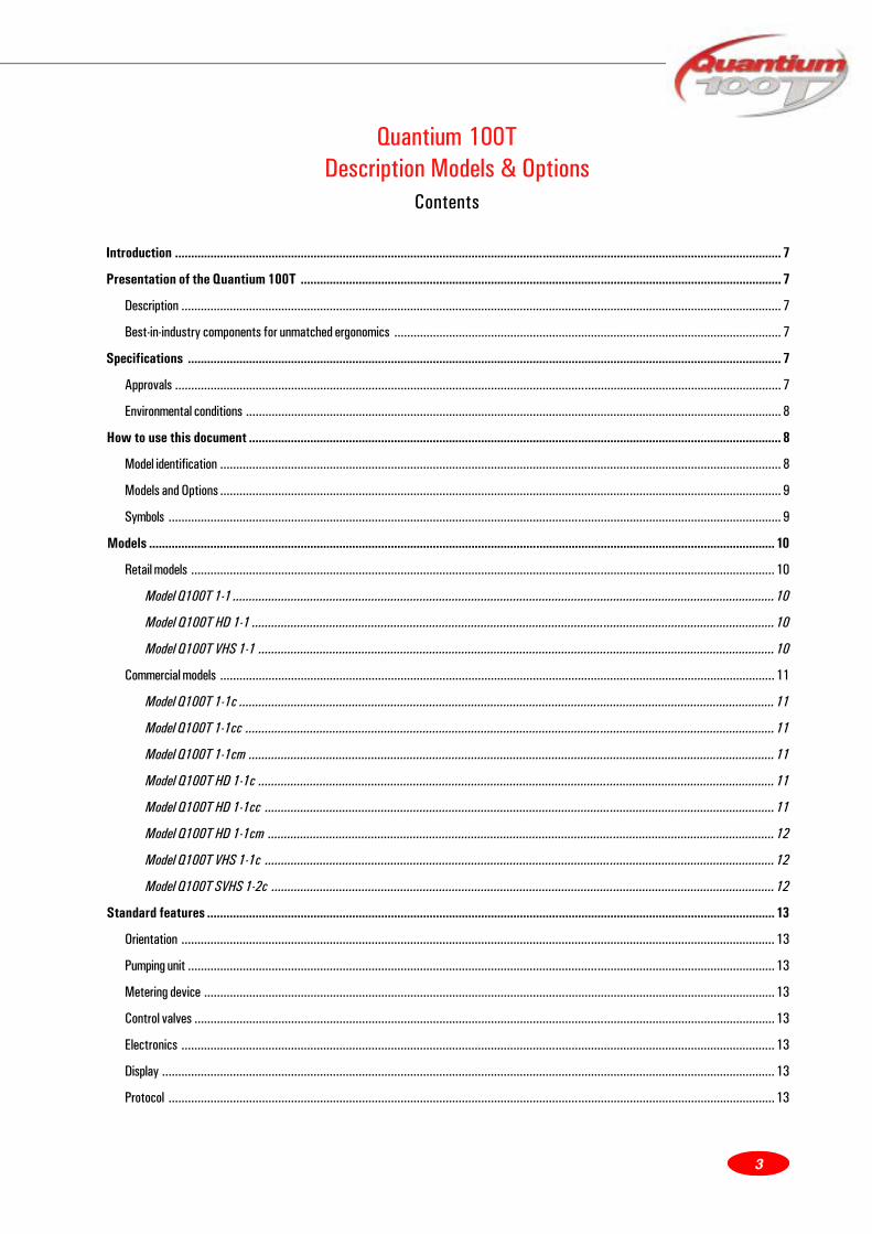
Introduction ............................................................................................................................................................................................ 7
Presentation of the Quantium 100T ..................................................................................................................................................... 7
Description .......................................................................................................................................................................................... 7
Best-in-industry components for unmatched ergonomics ........................................................................................................................ 7
Specifications ........................................................................................................................................................................................ 7
Approvals ............................................................................................................................................................................................ 7
Environmental conditions ...................................................................................................................................................................... 8
How to use this document ..................................................................................................................................................................... 8
Model identification .............................................................................................................................................................................. 8
Models and Options .............................................................................................................................................................................. 9
Symbols .............................................................................................................................................................................................. 9
Models .................................................................................................................................................................................................. 10
Retail models ..................................................................................................................................................................................... 10
Model Q100T 1-1 ........................................................................................................................................................................ 10
Model Q100T HD 1-1 .................................................................................................................................................................. 10
Model Q100T VHS 1-1 ................................................................................................................................................................ 10
Commercial models ............................................................................................................................................................................ 11
Model Q100T 1-1c ...................................................................................................................................................................... 11
Model Q100T 1-1cc .................................................................................................................................................................... 11
Model Q100T 1-1cm ................................................................................................................................................................... 11
Model Q100T HD 1-1c ................................................................................................................................................................ 11
Model Q100T HD 1-1cc .............................................................................................................................................................. 11
Model Q100T HD 1-1cm ............................................................................................................................................................. 12
Model Q100T VHS 1-1c .............................................................................................................................................................. 12
Model Q100T SVHS 1-2c ............................................................................................................................................................ 12
Standard features ................................................................................................................................................................................ 13
Orientation ........................................................................................................................................................................................ 13
Pumping unit ...................................................................................................................................................................................... 13
Metering device ................................................................................................................................................................................. 13
Control valves .................................................................................................................................................................................... 13
Electronics ........................................................................................................................................................................................ 13
Display .............................................................................................................................................................................................. 13
Protocol ............................................................................................................................................................................................ 13
Description Models & Options
4
Frame and cladding ............................................................................................................................................................................. 14
Nozzle ............................................................................................................................................................................................... 14
Hose ................................................................................................................................................................................................. 14
Hose system ..................................................................................................................................................................................... 14
Nozzle boot ........................................................................................................................................................................................ 14
Power ............................................................................................................................................................................................... 14
Livery ................................................................................................................................................................................................ 14
Totalisers .......................................................................................................................................................................................... 14
Transport .......................................................................................................................................................................................... 14
Options ................................................................................................................................................................................................. 15
GRVP ................................................................................................................................................................................................ 15
Mechanical totalisers ......................................................................................................................................................................... 15
Mechanical totalisers combined ........................................................................................................................................................... 15
Mechanical totaliser readable from outside .......................................................................................................................................... 15
Preset valves .................................................................................................................................................................................... 15
Nozzle OPW ....................................................................................................................................................................................... 15
Nozzle OPW dripfree .......................................................................................................................................................................... 15
Nozzle ZVA with dripcatcher ............................................................................................................................................................... 16
Nozzle ZVA dripstop ........................................................................................................................................................................... 16
Colour splashguard ZVA ..................................................................................................................................................................... 16
Nozzle latch ....................................................................................................................................................................................... 16
Nozzle boot locks ............................................................................................................................................................................... 16
Nozzle-mounted sight glass ................................................................................................................................................................. 16
Goodyear hose ................................................................................................................................................................................... 16
Elaflex low temperature hose ............................................................................................................................................................. 16
No hose, no nozzle .............................................................................................................................................................................. 16
Hose 5.5 m ....................................................................................................................................................................................... 17
Nozzle-mounted breakaway coupling (non-VR and VR) ............................................................................................................................ 17
40/80 speed selection ........................................................................................................................................................................ 17
Air vent pipes to outside of frame ...................................................................................................................................................... 17
Flexible coupling 1.5” female thread .................................................................................................................................................... 17
Flexible coupling 1.5” compression flange ............................................................................................................................................ 17
Submerged standard .......................................................................................................................................................................... 17
Submerged inlet shear valve OPW ....................................................................................................................................................... 18
Nefit adaptor ..................................................................................................................................................................................... 18
Filter with monitoring point ................................................................................................................................................................. 18
Single-phase motor ............................................................................................................................................................................. 18

5
Delta connection ................................................................................................................................................................................ 18
Second side display ............................................................................................................................................................................ 18
Preset keypad ................................................................................................................................................................................... 19
Spring mast ....................................................................................................................................................................................... 19
VR vacuum gauge visible ..................................................................................................................................................................... 19
VR safety shear valve ........................................................................................................................................................................ 19
Internal configuration keypad .............................................................................................................................................................. 19
Dispenser compatible with infrared remote control .............................................................................................................................. 19
LCD backlight .................................................................................................................................................................................... 19
Illuminated product indication .............................................................................................................................................................. 20
Emergency manual pumping device ...................................................................................................................................................... 20
Fleet management system compatible (EPS/TOK) ................................................................................................................................ 20
Fleet management system compatible (Cecli2) ..................................................................................................................................... 20
Empty calculator housing .................................................................................................................................................................... 20
Heater in calculator housing ................................................................................................................................................................ 20
Empty tank contact ........................................................................................................................................................................... 20
Painted columns ................................................................................................................................................................................. 21
Painted head ...................................................................................................................................................................................... 21
Stainless steel hydraulic doors ............................................................................................................................................................ 21
Stainless steel electronic door ............................................................................................................................................................ 21
Leak plate .......................................................................................................................................................................................... 21
Metax interface ................................................................................................................................................................................. 21
Programming switch .......................................................................................................................................................................... 21
Dispenser W&M sealing - France ........................................................................................................................................................ 22
Dispenser W&M sealing - Italy ............................................................................................................................................................ 22
Livery low cost .................................................................................................................................................................................. 22
Livery medium cost ............................................................................................................................................................................ 22
Livery high cost ................................................................................................................................................................................. 22
Reinforced packaging .......................................................................................................................................................................... 22
Export packaging ............................................................................................................................................................................... 22
Accessories ........................................................................................................................................................................................... 23
Standard User Access Keypad (UAK) .................................................................................................................................................. 23
Ground frame .................................................................................................................................................................................... 23
Dimension specification ...................................................................................................................................................................... 24
Appendix: Product Option Matrix rev. 13 ........................................................................................................................................... 25
Description Models & Options
6
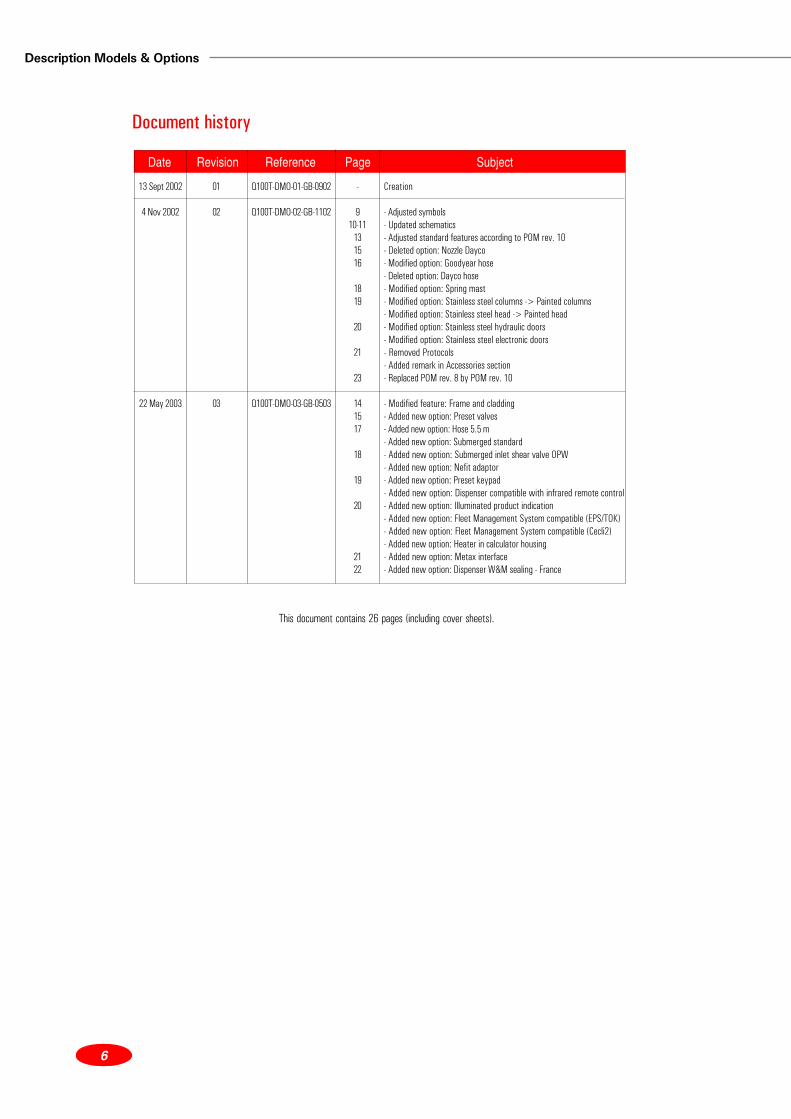
This document contains 26 pages (including cover sheets).
Date Revision Reference Page Subject
Document history
13 Sept 2002
4 Nov 2002
22 May 2003
01
02
03
Q100T-DMO-01-GB-0902
Q100T-DMO-02-GB-1102
Q100T-DMO-03-GB-0503
Creation
- Adjusted symbols- Updated schematics- Adjusted standard features according to POM rev. 10- Deleted option: Nozzle Dayco- Modified option: Goodyear hose- Deleted option: Dayco hose- Modified option: Spring mast- Modified option: Stainless steel columns -> Painted columns- Modified option: Stainless steel head -> Painted head- Modified option: Stainless steel hydraulic doors- Modified option: Stainless steel electronic doors- Removed Protocols- Added remark in Accessories section- Replaced POM rev. 8 by POM rev. 10
- Modified feature: Frame and cladding- Added new option: Preset valves- Added new option: Hose 5.5 m- Added new option: Submerged standard- Added new option: Submerged inlet shear valve OPW- Added new option: Nefit adaptor- Added new option: Preset keypad- Added new option: Dispenser compatible with infrared remote control- Added new option: Illuminated product indication- Added new option: Fleet Management System compatible (EPS/TOK)- Added new option: Fleet Management System compatible (Cecli2)- Added new option: Heater in calculator housing- Added new option: Metax interface- Added new option: Dispenser W&M sealing - France
-
910-11
131516
1819
20
21
23
141517
18
19
20
2122

7
Introduction
The purpose of this publication is to assist in the identification of the range of Quantium 100T models.
The basic information for the Quantium 100T and descriptions of the various available options are included.
This publication is part of a set of documents specifically produced for the Quantium 100T range. For further technical
information, please refer to the relevant associated publication.
Presentation of the Quantium 100T
Description
The Quantium 100T is a range of low-end single dispensers comprising:
• The Quantium 100T commercial (volume only) dispenser sub-range,
• The Quantium 100T retail dispenser sub-range.
All models are island-oriented and have the hose on the right hand side when looking at A-side.
Best-in-industry components for unmatched ergonomics
Built using proven components, the Quantium 100T is an industry reference in terms of ergonomics and performance.
The EPZ pump and the MA 26 meter device are twinned with the WWC T1 calculator at the heart of the configuration,
making Quantium 100T the most reliable and best-performing dispenser in its category.
Specifications
Approvals
All models will require both safety and weights and measures approvals in each country in which they will be marketed.
The major, specific approvals to be included initially include the following:
• NMI (Dutch Weights and Measures) – Certification to OIML standards and EMC verification.
• TÜV (Germany) – Safety certification
• SIRA (UK) – Certification to CEN
Above safety certificates to be used as a basis to gain safety certification and approvals for all other intended market
countries.

Description Models & Options
8
Local / country specific W&M, additional safety, and VR approvals have to be secured before sales are commenced.
All CE Directives (Machinery, EMC and eventually ATEX) also have to be in place and handled by engineering and the
factory during the design phase.
Environmental conditions
Ambient temperature: -25°C to +55°C for the standard model
Temperature of fluid: -25°c to +25°C
Viscosity of fluid: < 10-4 m²/s
Relative humidity: 5% to 95% non-condensing
Climate: Marine, tropical, industrial and polar
Altitude: from sea level to 2000 m
How to use this document
Model identification
On the following pages, a code is used to identify the model. This code is explained below.
• The first number in the Tokheim code used in the matrices relates to the number of products.
• The second number relates to the number of hoses.
• The “c” at the end means that the dispenser is a commercial dispenser with WWC T1 calculator.
• The “cc” at the end means that the dispenser is a commercial dispenser with a Cecli2 calculator.
• The “cm” at the end means that the dispenser is a commercial dispenser with mechanical register.
The following identifications of "speed" are used to qualify the nominal flow rates at which products are delivered by
the dispensers:
• StdS means Standard Speed, a nominal flow rate of 40 l/min. for VR and 50 l/min. for non-VR,
• HD means High Delivery, a nominal flow rate of 80 l/min.,
• VHS means Very High Speed, a nominal flow rate of 130 l/min.

9
Models and Options
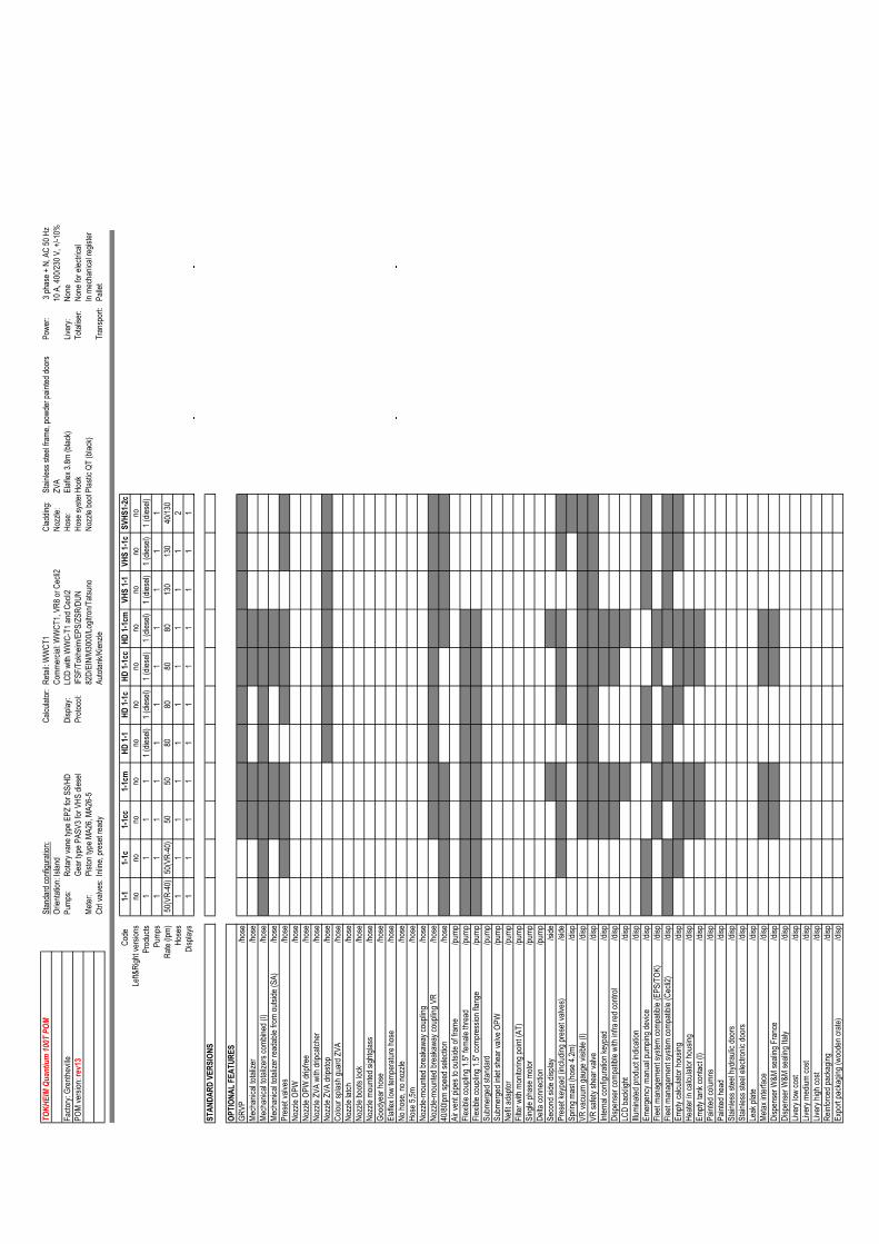
Models and Options are displayed in a matrix which presents standard models in a line and available options in a column.
A grey box indicates that the corresponding line option is not available on the corresponding column model. The
Quantium 100T matrix is presented as an appendix to the present document.
Symbols
Meter
Volume only display
Display mechanicalregister
LPG meter + valve
Slave display
Display WWC
EPZ pump
LPG air separator Solenoid valve
Nozzle boot + lpm
Display Cecli2
PAS V3 pump
Description Models & Options
10
Models
Retail models
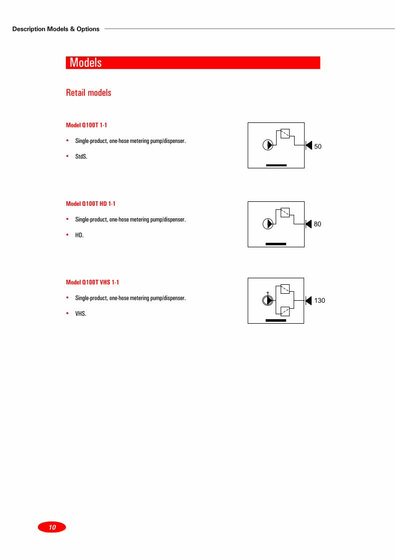
Model Q100T 1-1
• Single-product, one-hose metering pump/dispenser.
• StdS.
Model Q100T HD 1-1
• Single-product, one-hose metering pump/dispenser.
• HD.
Model Q100T VHS 1-1
• Single-product, one-hose metering pump/dispenser.
• VHS.
80
130
50

11
Commercial models
Model Q100T 1-1c
• Single-product, one-hose metering pump/dispenser with volume
only calculator (WWC T1).
• StdS.
Model Q100T 1-1cc
• Single-product, one-hose metering pump/dispenser with volume
only calculator (Cecli2).
• StdS.
Model Q100T 1-1cm
• Single-product, one-hose metering pump/dispenser with volume
only mechanical register (VR8).
• StdS.
Model Q100T HD 1-1c
• Single-product, one-hose metering pump/dispenser with volume
only calculator (WWC T1).
• HD.
Model Q100T HD 1-1cc
• Single-product, one-hose metering pump/dispenser with volume
only calculator (Cecli2).
• HD.
80
50
50
50
50
Description Models & Options
12
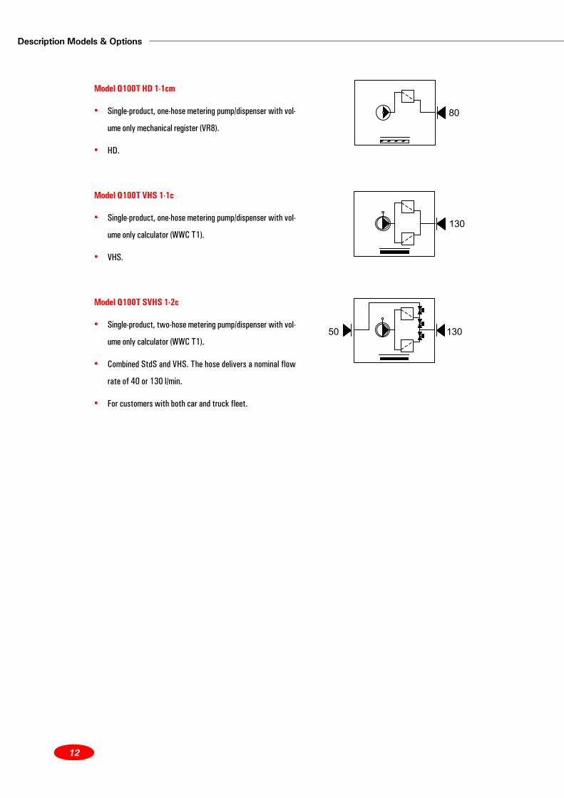
Model Q100T HD 1-1cm
• Single-product, one-hose metering pump/dispenser with vol-
ume only mechanical register (VR8).
• HD.
Model Q100T VHS 1-1c
• Single-product, one-hose metering pump/dispenser with vol-
ume only calculator (WWC T1).
• VHS.
Model Q100T SVHS 1-2c
• Single-product, two-hose metering pump/dispenser with vol-
ume only calculator (WWC T1).
• Combined StdS and VHS. The hose delivers a nominal flow
rate of 40 or 130 l/min.
• For customers with both car and truck fleet.
80
130
50 130

13
Standard features
Orientation
• Island-oriented with hose connection ready to take hose.
• Hook hose system big enough to hold two ‘loops’ (either next or on top of each other).
Pumping unit
• EPZ pumping unit for standard speed (StdS) and high-speed (HS) delivery with integrated filter (70 micron plastic
re-usable) and built-in foot valve (check valve).
• PASV3 for very high speed (VHS) diesel with external vertical filter box (90 micron plastic re-usable) and built-in
foot valve (check valve).
Metering device
• MA 26 mechanically calibrated 4-pistons meter with integrated MP T1 pulser for electronic dispensers.
• MA 26-5.
Control valves
• Inline valves, 24V, allowing two-stage configuration for preset applications.
Electronics
• For retail models: WWC T1 calculator with liquid crystal displays for Money (1”), Volume (1”) and Grade Price (1/
2”).
• For commercial models: WWC T1, Veeder Root VR8 mechanical register with mechanical reset (model with ‘m’
suffix) or Cecli2.
Display
• LCD displays with WWC T1 and Cecli2.
Protocol
• IFSF – Tokheim – EPS – ZSR – Dunclare – 82D – EIN (JKR) – M3000 – Logitron – Tatsuno – Autotank – Kienzle.
Description Models & Options
14
Frame and cladding
• Galvanised steel for internal bracketing.
• Stainless steel for outer frame (hydraulic cabinet and electronic head).
• Powder-painted electronic and hydraulic doors.
Nozzle
• ZVA.
Hose
• Elaflex 3.8 m (black).
Hose system
• Hook.
Nozzle boot
• Plastic Quantium T nozzle boot (black).
Power
• Three-phase +N, AC 50 Hz, 10 A, 400/230 V, +/-10%.
Livery
• Not part of the standard configuration and always has to be selected as an option (see Options).
Totalisers
• None for electrical.
• Standard for mechanical register.
Transport
• Pallet.

15
Options
GRVP
• Mechanically controlled Elaflex GRVP vapour recovery system with ZVA nozzle, Elaflex hose, Dürr vacuum pump,
one return line per dispenser (with single dispensers this automatically is VR return line per product).
Mechanical totalisers
• Driven by meter and mounted directly on meter.
• Easily readable by only opening one door / panel.
Mechanical totalisers combined
• For configurations with two meters delivering one product (very high speed). For taxation reasons.
• Used in Italy.
Mechanical totaliser readable from outside
• MOC requirement in South Africa.
Preset valves
• These valves differ from normal stop-valves in that they can control the speed of the fuel flow in more than one
ratio.
• They enable the “slower” filling up of the tank that is needed where of a preset option has been selected on the
dispenser, via the forecourt controller or a payment terminal.
• The preset valve will be available for every fuel grade type (for LPG it can only be driven remotely by POS), every
flow rate and every hydraulic frame position.
Nozzle OPW
• OPW nozzle (non-VR version) instead of ZVA.
Nozzle OPW dripfree
• OPW nozzle (non-VR version) with similar function to ZVA with drip catcher.
Description Models & Options
16
Nozzle ZVA with dripcatcher
• ZVA nozzle with a ring on the nozzle spout, which prevents drips from soiling the nozzle (used on diesel nozzles).
Nozzle ZVA dripstop
• ZVA nozzle with a special device that prevents from drips.
Colour splashguard ZVA
• Splash guard to be added to ZVA nozzles.
Nozzle latch
• Latching device allowing the nozzle trigger to be blocked in ‘delivering’ position without having to keep it pressed.
Nozzle boot locks
• A lock that enables owner to lock the nozzle to its boot when the forecourt is closed.
Nozzle-mounted sight glass
• A sight glass inserted between nozzle and hose.
Goodyear hose
• As an alternative to standard Elaflex hose.
• Not available for VR.
Elaflex low temperature hose
• Hoses whose material quality is suitable for usage in a low temperature environment.
• Not available for LPG.
No hose, no nozzle
• For export markets where hoses and nozzles from local suppliers are used.
• Dispenser does not have CE sticker and type plates.
17
Hose 5.5 m
• Goodyear hose 5.5 m, alternative to standard hose.
Nozzle-mounted breakaway coupling (non-VR and VR)
• This is a coupling that will prevent spillage if the hose and the nozzle are forced apart in such a way as to cause
leakage (e.g., a drive-off with the nozzle still inserted in the car tank opening).
• It should be noted that breakaway couplings restrict the flow rate to a certain degree.
40/80 speed selection
• Available on all HS dispensers except for ‘cc’ models.
• For the HS diesel nozzles, the standard flow rate is 40 l/min. A push button enables to select a higher flow rate for
trucks, 80 l/min.
Air vent pipes to outside of frame
• A pipe between the pumping unit vent and the outside of the frame with a defined outlet for the evacuation of any
liquid ejected through the vent.
• Used in Italy.
Flexible coupling 1.5” female thread
• Flexible metal connector from filter pot of the pumping unit to a female 1.5” thread accepting a 1.5” BSP pipe that
comes from underground to feed the dispenser.
• Hydraulic inlet option for PASV3.
Flexible coupling 1.5” compression flange
• Flexible metal connector from filter pot of the pumping unit to a female 1.5” O-ring compression flange set
accepting an unthreaded 1.5” pipe that comes from underground to feed the dispenser.
• Hydraulic inlet option for PASV3.
Submerged standard
• The dispenser is not equipped with any suction pumps, but gets its fuel through submersible pumps.
• Instead of a suction pump, the “standard” submerged dispenser has only a filter.
Description Models & Options
18
• It will be available for every hydraulic frame position.
• It must be fitted with a safety shear valve that makes sure that the liquid column is sealed if an accident should
happen and the dispenser is disconnected from the island (not included).
Submerged inlet shear valve OPW
• A shear valve located between dispenser inlet and ground connection.
• In case the dispenser is hit and forced of its island, the shear valve will close to prevent the pressurized submerge
system to spill its fuel to the environment.
Nefit adaptor
• Used in Spain.
Filter with monitoring point
• Each filter pot is fitted with a small ball valve with a threaded connection which can be used to introduce air into
the pump inlet. There is also a check valve mounted between the ball valve and the filter pot (to prevent liquid
escape from the filter pot).
• This option is needed because in some countries the metrology state officer has to be able to check without the use
of any tools that the dispenser switches off when air enters the system.
• Mandatory in Austria.
Single-phase motor
• An alternative 230V, 50 Hz motor.
• Mainly used in the UK and Africa.
Delta connection
• A connection in “delta” instead of “star” configuration for three-phase motors.
• Mainly used in Belgium.
Second side display
• Standard dispenser only has one display. For double-sided use a display should be added to the other side of the
dispenser.
19
Preset keypad
• Kaypad that allows the customer to choose a preset amount of money or fuel.
• Once a selection is made, the dispenser automatically delivers the right amount (via the electronics and the above-
mentioned preset keypad).
• Preset valves are included in this option (see above).
Spring mast
• Alternative to the standard hook system for a more user-friendly storage of the hose (actual hose length: 4.2 m).
VR vacuum gauge visible
• A vacuum type gauge, visible from the outside, positioned between the vacuum pumps and the proportional valves
to monitor function of VR system.
• As per Italian regulations.
VR safety shear valve
• A shear valve located between dispenser VR return pipe and ground connection.
• To be supplied separate from dispenser.
Internal configuration keypad
• A simple configuration keypad that is permanently stored inside the calculator head.
• See WWC T1 Setup and Maintenance Manual.
Dispenser compatible with infrared remote control
• The dispenser is delivered with a calculator that can be programmed via a remote control.
• This infra red remote control is not an option for the dispenser and must be ordered separately.
LCD backlight
• To improve readability of the display when it is dark (preferably using a single light bulb).
Description Models & Options
20
Illuminated product indication
• The product identification panels located in the electronic head are separately illuminated.
Emergency manual pumping device
• In case of long mains interruption, it is possible to operate the dispenser with a hand krank.
• The models with electronic calculator are fitted with a high-capacity battery.
• The models with mechanical register have a manual reset.
Fleet management system compatible (EPS/TOK)
• An additional pulse output is provided to be connected to a third party fleet management system.
• Electronic models only, except ‘cc’ models.
• For EPS protocol.
Fleet management system compatible (Cecli2)
• An additional pulse output is provided to be connected to a third party fleet management system.
• Electronic models only, except ‘cc’ models.
• For Cecli2 protocol.
Empty calculator housing
• To fit third party calculator. Product liability is with third party.
• Empty means there is no calculator and no display but cabling and glands for following functions should be available:
motors (with thermal protection in head cables are routed into the head anyway), power supply (glands), valves and
pulsers.
• Mainly for Germany, Denmark, Spain and Austria.
Heater in calculator housing
• For low temperature markets, to prevent the LCD display from “freezing”.
Empty tank contact
• A signal send to the dispenser when the main storage tank is empty putting the dispenser ‘on hold’. When picking

21
up the nozzle no delivery is possible. Only with WWC T1 calculator. Uses IEB board.
• Mandatory in Italy.
Painted columns
• Hydraulic columns (side panels) painted.
Painted head
• Calculator head painted.
Stainless steel hydraulic doors
• Hydraulic doors in mirror finished stainless steel.
• By selecting this option and/or the “Stainless steel electronic door” option, no livery option has to be selected, i.e.
the price of the stainless steel hydraulic doors includes the painted electronic doors.
Stainless steel electronic door
• Electronic doors in mirror finished stainless steel.
• By selecting this option and/or the “Stainless steel hydraulic door” option, no livery option has to be selected, i.e.
the price of the stainless steel hydraulic doors includes the painted electronic doors.
Leak plate
• A plate mounted in the dispenser to prevent fuel leaking into the ground.
Metax interface
• Only available with Tatsuno protocol.
• Used in Scandinavia.
Programming switch
• A safety system, which allows programming of the calculator only if it is switched on.
• Mandatory in certain countries, required by some customers in other countries.
Description Models & Options
22
Dispenser W&M sealing - France
• Additional type plates per product.
• Mandatory in France.
Dispenser W&M sealing - Italy
• Seals all connections/joints in the fuel line after the meter.
• Mandatory in Italy.
Livery low cost
• Single colour for the complete dispenser.
Livery medium cost
• Two colours on the dispenser or one colour and single-colour logo.
Livery high cost
• Three colours or more (including colours on logos, if required).
Reinforced packaging
• For shipments where the material suffers from additional load (for instance when multiple transport companies are
used.
Export packaging
• Wooden crate for shipments to export markets.

23
Accessories
Standard User Access Keypad (UAK)
• For programming by service engineer.
Ground frame
• A frame that will be fixed in the concrete island-foundation of the dispenser. It should allow the throughput of all
piping, cabling, etc. and the fixation of the main mechanical parts like hydraulic frames, columns, shear valves etc.
to the ground.
Please note that Accesoories have to be ordered from the Spare Parts Centres and not the Manufacturing Centres.

Description Models & Options
24
Dimension specification
TOKH
EIM
Quan
tium
100T
POM
Stan
dard
confi
gura
tion:
Calcu
lator
:Re
tail: W
WCT
1Cl
addin
g:St
ainles
s stee
l fram
e, po
wder
paint
ed do
ors
Powe
r: 3
phas
e + N
, AC
50 H
zOr
ientat
ion:Is
land
Comm
ercia
l: WW
CT1,
VR8 o
r Cec
li2No
zzle:
ZVA
10 A
, 400
/230 V
, +/-1
0%Fa
ctory:
Gre
nthev
illePu
mps:
Rotar
y van
e typ
e EPZ
for S
S/HD
Disp
lay:
LCD
with
WW
C-T1
and C
ecli2
Hose
:El
aflex
3.8m
(blac
k)Liv
ery:
None
POM
versi
on: r
ev13
Gear
type
PAS
V3 fo
r VHS
dies
elPr
otoco
l:IF
SF/T
okhe
im/E
PS/Z
SR/D
UNHo
se sy
stemH
ook
Total
iser:
None
for e
lectric
alMe
ter:
Pisto
n typ
e MA2
6, MA
26-5
82D/
EIN/
M300
0/Log
itron/T
atsun
oNo
zzle
boo t
Plas
tic Q
T (b
lack)
In me
chan
ical re
gister
Ctrl v
alves
:Inli
ne, p
rese
t rea
dyAu
totan
k/Kien
zleTr
ansp
ort:
Palle
t
Code
1-1
1-1c
1-1c
c1-
1cm
HD 1-
1HD
1-1c
HD 1-
1cc
HD 1-
1cm
VHS
1-1
VHS
1-1c
SVHS
1-2c
Left&
Righ
t ver
sions
nono
nono
nono
nono
nono
noPr
oduc
ts1
11
11 (
diese
l)1 (
diese
l)1 (
diese
l)1 (
diese
l)1 (
diese
l)1 (
diese
l)1 (
diese
l)Pu
mps
11
11
11
11
11
1Ra
te (lp
m)50
(VR-
40)
50(V
R-40
)50
5080
8080
8013
013
040
/130
Hose
s1
11
11
11
11
12
Disp
lays
11
11
11
11
11
1
STAN
DARD
VER
SION
S
OPTI
ONAL
FEA
TURE
SGR
VP/ho
seMe
chan
ical to
talize
r/ho
seMe
chan
ical to
talize
rs co
mbine
d (I)
/hose
Mech
anica
l total
izer r
eada
ble fr
om ou
tside
(SA)
/hose
Pres
et va
lves
/hose
Nozz
le OP
W/ho
seNo
zzle
OPW
dripf
ree
/hose
Nozz
le ZV
A wi
th dr
ipcatc
her
/hose
Nozz
le ZV
A dr
ipstop
/hose
Colou
r spla
sh gu
ard Z
VA/ho
seNo
zzle
latch
/hose
Nozz
le bo
ots lo
ck/ho
seNo
zzle
moun
ted si
ghtgl
ass
/hose
Good
year
hose
/hose
Elafl
ex lo
w tem
pera
ture h
ose
/hose
No ho
se, n
o noz
zle/ho
seHo
se 5,
5m/ho
seNo
zzle-
moun
ted br
eaka
way c
oupli
ng/ho
seNo
zzle-
moun
ted br
eaka
way c
oupli
ng V
R/ho
se40
/80lpm
spee
d sele
ction
/hose
Air v
ent p
ipes t
o outs
ide of
fram
e/pu
mpFle
xible
coup
ling 1
.5" fe
male
threa
d /pu
mpFle
xible
coup
ling 1
.5" co
mpre
ssion
flang
e/pu
mpSu
bmer
ged s
tanda
rd/pu
mpSu
bmer
ged i
nlet s
hear
valve
OPW
/pump
Nefit
adap
tor/pu
mpFil
ter w
ith m
onito
ring p
oint (
AT)
/pump
Sing
le ph
ase m
otor
/pump
Delta
conn
ectio
n/pu
mpSe
cond
side
disp
lay/si
dePr
eset
keyp
ad (in
cludin
g pre
set v
alves
)/si
deSp
ring m
ast (
hose
4.2m
)/di
spVR
vacu
um ga
uge v
isible
(I)
/disp
VR sa
fety s
hear
valve
/disp
Inter
nal c
onfig
urati
on ke
ypad
/disp
Disp
ense
r com
patib
le wi
th inf
ra re
d con
trol
/disp
LCD
back
light
/disp
Illumi
nated
prod
uct in
dicati
on/di
spEm
erge
ncy m
anua
l pum
ping d
evice
/disp
Fleet
mana
geme
nt sy
stem
comp
atible
(EPS
/TOK
)/di
spFle
et ma
nage
ment
syste
m co
mpati
ble (C
ecli2
)/di
spEm
pty ca
lculat
or ho
using
/disp
Heate
r in ca
lculat
or ho
using
/disp
Empty
tank
conta
ct (I)
/disp
Paint
ed co
lumns
/disp
Paint
ed he
ad/di
spSt
ainles
s stee
l hyd
rauli
c doo
rs/di
spSt
ainles
s stee
l elec
tronic
door
s/di
spLe
ak pl
ate/di
spMe
tax in
terfac
e/di
spDi
spen
ser W
&M se
aling
Fra
nce
/disp
Disp
ense
r W&M
seali
ng Ita
ly/di
spLiv
ery l
ow co
st/di
spLiv
ery m
edium
cost
/disp
Liver
y high
cost
/disp
Reinf
orce
d pac
kagin
g/di
spEx
port
pack
aging
(woo
den c
rate)
/disp
DIRECT OPERATIONS
AustriaTokheimEitzenberger straße 4-6A-2544 Leobersdorf☎ +43 (0) 2256 606 0
+43 (0) 2256 606 170
BelgiumTokheimEverdongenlaan 312300 Turnhout☎ +32 (0) 14 44 85 00
+32 (0) 14 44 85 55
Czech RepublicTokheim Pernerova 48CZ - 186 02 Prague 8☎ +420 2 24890312
+420 2 232 72 67
Denmark & ScandinaviaTokheimHejrevang 103450 Allerød☎ +45 48 14 14 00
+45 48 17 45 96
FranceTokheim (Corporate headquarters)ZAC Paris Nord 2B.P. 4002795912 Roissy C.D.G. Cedex☎ +33 (0)1 49 90 77 00
+33 (0)1 49 90 77 77
FranceTokheim Services France9, avenue Galilée92350 Le Plessis Robinson☎ +33 (0)1 41 36 13 00
+33 (0)1 41 36 13 70
GermanyTokheim GmbHLothstrasse 1aD-80335 München☎ +49 (0)89 18953-0
+49 (0)89 18953-399
ItalyTokheim SofitamQuattordio KM 10800S.P. 2614030 Scurzolengo (AT)☎ +39 0141 2038200
+39 0141 2038222
NetherlandsTokheimTouwslagerstraat 17Postbus 41862980 GD Ridderkerk☎ +31 180 481500
+31 180 481555
NorwayTokheimVerkseier Furulunds vei 11BP.O. Box 45 - Alnabru0614 Oslo☎ +47 22 90 49 50
+47 22 90 49 51
PolandPol-Germann TokheimUL Narwicka 180557 Gdansk☎ +48 58 343 21 71
+48 58 343 22 15
PortugalG.N.C.Parque de ciencia e TecnologiaEdificio Tecnologia I, N° 272780 OeirasLisboa☎ +351 (0)1 422 04 20
+351 (0)1 421 42 26
RussiaTokheim Representative OfficeRoome 380 - Hotel “Ukraina”Kutuzovski prospekt, 2/1, stroyenie 1Moscow, 121249 Russia☎ +7 (095) 933 69 35
+7 (095) 933 69 34
Slovak RepublicTokheimMlynske Nivy 70SK- 82015 Bratislava☎ +421 7 58270215
+421 7 53414123
SpainKoppens IbericaCalle Imprenta 5Poligono industrial de Alcobendas28100 Alcobendas (Madrid)☎ +34 91 661 28 13
+34 91 661 41 30
SwitzerlandTokheimRoute du Crochet 7Case postale 501762 Givisiez☎ +41 (0)26 460 51 11
+41 (0)26 460 51 12
United KingdomTokheimUnit 3 Baker RoadWest Pitkero Industrial EstateDundee DD5 3RT☎ +44 (0)1382 598000
+44 (0)1382 598001
CameroonSocatamB.P. 3941Douala☎ +237 40 57 86
+237 40 57 88
MoroccoMatam209, bd. Moulay IsmailRoute de RabatCasablanca☎ +212 22 40 40 24
+212 22 40 40 21
SenegalCosetamQuartier de Bel AirRoute des HydrocarburesBP 1237Dakar☎ +221 832 23 71
+221 832 68 34
South AfricaTokheimStand 110 Precision RoadKya Sand, Randburg☎ +27 11 4622105
+27 11 4621942
TunisiaCottam116, av. de l’Union du Maghreb ArabeB.P. 117La Soukra2036 Tunis☎ +216 1 759 550
+216 1 765 943
MIDDLE EAST, SOUTH CENTRALAMERICA, AFRICATokheimZAC Paris Nord 2B.P. 4002795912 Roissy C.D.G. CedexFrance☎ +33 (0)1 49 90 77 56 - 77 31
+33 (0)1 49 90 77 93
ASIATokheimPOBOX # 16869JAFZDubai UAE☎ +971 4 881 3305
+971 4 881 4463
A
RFC
MA
SN
ZA
TN
N
PL
P
RUS
SK
B
CZ
DK
F
F
D
I
NL
E
CH
GB
Tokheim
As Tokheim regularly improves its products to ever betterrespond to evolving market and regulatory requirements, itreserves the right to change any of the specifications of theseproducts, and this without prior notice.
Q100T-DMO-03-GB-0503www.tokheim.com