specifications - missouri department of … · specifications for constructing or improving ifb 9...
TRANSCRIPT

MISSOURI
HIGHWAYS and TRANSPORTATION
COMMISSION
JEFFERSON CITY, MISSOURI
SPECIFICATIONS
FOR
CONSTRUCTING OR IMPROVING
IFB 9 – 060927A
District 3 Automatic Sliding Door Installation
Hannibal, MO

TABLE OF CONTENTS
DIVISION PAGE DIVISION 0 - BIDDING AND CONTRACT INFORMATION BIDDER CHECKLIST FINAL CHECKLIST BEFORE SUBMITTING PROPOSAL 1 NEWSPAPER ADVERTISEMENT NOTICE TO CONTRACTORS 2 00020 INVITIATION TO BID 3 00100 INSTRUCTIONS TO BIDDER 4 00301 BID FORM 9 00430 SUBCONTRACTOR LISTING 11 00600 BID BOND 12 PREVAILING WAGE DETERMNATION INSERT DIVISION 1 – GENERAL REQUIREMENTS 01010 GENERAL CONDITIONS 13 01011 SUPPLEMENTARY CONDITIONS 16 01019 CONTRACT CONSIDERATIONS 17 01039 COORDINATION AND MEETINGS 19 01300 SUBMITTALS 22 01400 QUALITY CONTROL 25 01500 CONSTRUCTION FACILITIES AND TEMPORARY CONTROLS 27 01600 MATERIAL AND EQUIPMENT 29 01650 STARTING OF SYSTEMS 31 01700 CONTRACT CLOSEOUT 32 DIVISION 7 - THERMAL AND MOISTURE PROTECTION 07900 JOINT SEALERS 34 DIVISION 8 – DOORS AND WINDOWS 08460 AUTOMATIC SLIDING DOOR SYSTEM 36 08800 GLAZING 40 DIVISION 16 - ELECTRICAL 16100 ELECTRICAL WORK 45

BIDDER CHECKLIST
FINAL CHECKLIST BEFORE SUBMITTING PROPOSAL
_____1. The orange bound Request for Proposal includes a complete set of bidding forms, specifications, and
appendices, which are made part of the proposal by reference. It is for the bidders information and convenience only and is not to be returned with the proposal.
_____2. The blue bound Proposal contains a complete set of bidding forms only. It is to be completed, executed
and submitted in a sealed envelope marked " Automatic Sliding Door Installation” _____ a. Complete the Bid Form by filling in the total dollar amount of the bid; listing any
addenda which may have been issued; filling in the dollar amount of the bidder's check or Bid Bond, sign the proper signature line, and supply the required information in connection with the signature for the individual bidder, joint adventurer, or corporation.
_____ b. Submit Bid Bond executed by the bidder and surety. The bidder may use the Bid Bond
furnished by the Commission or AIA Document A310 or approved equivalent or attach cashier's check to Bid Bond form. Personal checks are not accepted.
_____ c. Complete Subcontractor section by listing major subcontractor(s) and general
supervisor(s), sign as required. _____ d. Complete Certification Regarding Missouri Domestic Products Procurement Act
section, if applicable. _____3. If addenda are issued attach to the back of the blue bound Proposal. Copy addenda and add to the
appropriate section of the orange bound Request for Proposal and retain for your records.
Page 1

NEWSPAPER ADVERTISEMENT
Notice to Contractors Bids for constructing Automatic Sliding Door Installation, , Hannibal, Mo will be received by the Missouri Department of Transportation at its One Stop Facility located at 1320 Creek Trail Drive, P.O. Box 270, Jefferson City, MO 65102 until 1:00 p.m. September 20, 2006. Please contact Sherry King by calling 573/522-5591 or by e-mail at [email protected] to request copies of the Contract forms, specifications, plans and information or electronically down-load them from http://www.modot.org/business/contractor_resources/FacilitiesConstructionandMaintenance.htmPrevailing wage as established by the Missouri Department of Labor and Industrial Relations, for Marion County, as shown in the proposal will apply. Bid awards shall be based on bids submitted and evaluated. Bid securities in the amount of 5% of the total bid submitted by the bidder are required to accompany bid. Site visits are scheduled for September 13, 2006, at the District Three Office, Located at 1711 South Highway 61, Hannibal, MO, in the upstairs conference room at 10:00 a.m.
Page 2

00020
INVITIATION TO BID
SECTION
Notice is given hereby that the Missouri Department of Transportation will accept bids for construction of the proposal marked "Proposal for Automatic Sliding Door Installation", according to Specifications, and described in general as:
Removing (4) existing storefront door units and installing (4) automatic sliding door units with optional transoms to fit existing 11’-0” wide x 9’-11” high openings. Provide electric service to each door unit as required for a complete and operational system.
Sealed bids will be received by the Missouri Department of Transportation at its One Stop Facility located at 1320 Creek Trail Drive, P.O. Box 270, Jefferson City, MO 65102 until 1:00 p.m. September 20, 2006. Bids will be opened and read aloud at that time and that place. Bids received after that time will not be accepted. Bidders may secure copies of contract forms, specifications, plans and information by contacting Sherry King by phone at 573/522-5592, by e-mail, [email protected] or electronically down-load them from http://www.modot.org/business/contractor_resources/FacilitiesConstructionandMaintenance.htm Prevailing wages as established by the Missouri Department of Labor and Industrial Relations, for Marion County, as shown in the Proposal, will apply. Bid securities in the amount of 5% of the bid will be required to accompany bids. Proposals must be made on forms provided by the Commission. The Commission reserves the right to reject any or all bids and to waive irregularity in the bids and the bidding. No bid may be amended or withdrawn after the bid is opened. Site visits are scheduled for September 13, 2006, at the District Three Office, Located at 1711 South Highway 61, Hannibal, MO, in the upstairs conference room at 10:00 a.m. MISSOURI HIGHWAY AND TRANSPORTATION COMMISSION ________________________________________________________ Building Design Supervisor
Page 3

00100
INSTRUCTIONS TO BIDDER
SECTION
1. SCOPE OF WORK
Removing (4) existing storefront door units and installing (4) automatic sliding door units with optional transoms to fit existing 11’-0” wide x 9’-11” high openings. Provide electric service to each door unit as required for a complete and operational system.
2. BID FORM In order to receive consideration, bids must be made in strict accordance with the following. A. Make bids, upon the forms provided herein, properly signed and with all items filled out. Do not
change the wording of the bid form and do not add words to the bid form. Unauthorized conditions, limitations or provisions attached to the bid will be cause for rejection of the bid.
B. No telegraphic bid or telegraphic modification of a bid will be considered. No bids received after
the time fixed for receiving them will be considered. Late bids will be returned to the bidder unopened.
C. Address bids to the Missouri Department of Transportation, and deliver to the address given in the
Invitation to Bid, on or before the day and hour set for opening the bids. Enclose each bid in a sealed envelope bearing the title of the Work, the name of the bidder, and the date and hour of the bid opening. Submit only the original signed copy of the bid. It is the sole responsibility of the bidder to see that the bid is received on time.
3. BONDS A. Bid securities, a cashiers check, a Bank Money Order, or a Certified Check made payable to
"Director of Revenue, Credit Road Fund", in the amount stated in the invitation to bid must accompany each bid. The successful bidder's security will be retained until he has signed the Contract and has furnished the required Certificates of Insurance.
B. The Owner reserves the right to retain the security of all bidders until the successful bidder enters
into the Contract. Other bid securities will be returned as soon as practicable. If any bidder refuses to enter into a Contract, the Owner may retain his bid security as liquidated damages but not as a penalty.
C. Prior to signing the Contract, the successful bidder will secure a Performance Bond in the amount
of 100% of the Contract Sum. The bond shall be issued by Surety, acceptable to the Owner. Costs of such bonds will be the responsibility of the bidder.
4. EXAMINATION OF DOCUMENTS AND SITE OF WORK Before submitting a bid, each bidder shall examine the Drawings carefully, read the Specifications and all
other proposed Contract Documents, and visit the site of the work. Each bidder shall fully inform himself, prior to bidding, as to existing conditions and limitations under which the Work is to be performed and shall include in his bid a sum to cover the cost of items necessary to perform the Work, as set forth in the proposed Contract Documents. No allowance will be made to a bidder because of lack of such examination or knowledge. The submission of a bid will be considered conclusive evidence that the bidder has made such examination.
Page 4

5. INTERPRETATION No oral interpretations will be made to any bidder as to the meaning of the plans and specifications or the
acceptability of alternate products, materials, form or type of construction. Every request for interpretation shall be made in writing and submitted with all supporting documents not less than ten (10) calendar days before opening of bids. The request shall be sent directly to the project Designer. Every interpretation made to a bidder will be in the form of an addendum and will be sent as promptly as is practicable to all persons to whom plans and specifications have been issued. All such addenda shall become part of the contract documents.
6. PROOF OF COMPETENCY OF BIDDER A bidder may be required to furnish evidence, satisfactory to the Commission, that he and his proposed
subcontractor(s) have sufficient means and experience in the types of work called for to assure completion of the Contract in a satisfactory manner.
7. WITHDRAWAL OF BIDS A. A bidder may withdraw his bid, either personally or by written request, at any time prior to the
scheduled time for opening bids. B. No bid may be amended or withdrawn after the bid is opened. 8. AWARD OR REJECTION OF BIDS
A. The Contract, if awarded, will be awarded to the responsible bidder who has proposed the lowest Contract Sum, subject to the Commission's right to reject any or all bids and to waive informality and irregularity in the bids and in the bidding.
B. Award of alternates, if any, will be made in numerical order to result in the maximum amount of
work being accepted within available construction funds. C. Bidder's proposal price shall include all city, state, and federal sales, excise and similar taxes which
may be lawfully assessed in connection with his performance of work and purchase of materials to be incorporated in the work.
9. EXECUTION OF CONTRACT A. The Contract, which the successful bidder will be required to execute, will be included in the
Contract Documents. B. The bidder to whom the Contract is awarded shall, within fourteen calendar days after notice of
award and receipt of Contract Documents from the Commission, sign and deliver required copies to the Commission.
C. Upon delivery of the signed Contract, the bidder to whom the Contract is awarded shall deliver to
the Commission those Certificates of Insurance required by the Contract Documents and Performance Bond, as required by the Commission.
Page 5

D. Execution of the Contract by the Commission must be done before the successful bidder may proceed with the work.
10. CONSTRUCTION TIME AND LIQUIDATED DAMAGES A. Time of Completion - If this proposal is accepted, it is hereby agreed that work will begin not later
than the date specified in the "Notice to Proceed" and will diligently be prosecuted in order to complete the work and billing within 40 working days from the date specified. Completion of work will be based on FINAL ACCEPTANCE of the building; "SUBSTANTIAL COMPLETION" will not be accepted as basis for completion.
B. Liquidated Damages - It is agreed that time is of the essence. Because failure to complete the
contract within the time fixed herein will cause serious inconvenience, loss, and damage to the state, liquidated damages will be assessed in the amount of $300.00 per working day, for each working day after the agreed completion date that the Work is not fully completed.
11. NONDISCRIMINATION
A. The Bidder/Offeror understands that this project involves state funds and the Bidder/Offeror awarded the contract will be required to comply with the Executive Order 05-30 of the Governor of the State of Missouri dated September 8, 2005. This order stipulates that there shall be no discriminatory employment practices by the Contractor or his subcontractors, if any, based on race, sex, religion, national origin, age, color, disability, or veteran status. The undersigned Contractor or his subcontractors, if any, shall give written notice of their commitments under this clause to any labor union with which they have bargaining or other agreements.
B. The Contractor shall comply with the Regulations relative to nondiscrimination in federally-assisted programs of the Department of Transportation, Title 49, Code of Federal Regulations, Part 21, as they may be amended from time to time, (hereinafter referred to as the Regulations), which are herein incorporated by reference and made a part of this contract.
C. All solicitations either by competitive bidding or negotiation made by the Contractor for work to be performed under a subcontract, including procurements of materials or leases of the Contractor's obligations under this contract and the Regulations, will be relative to nondiscrimination on the grounds of race, color, or national origin.
D. Sanctions for Noncompliance: In the event of the Contractor's noncompliance with the nondiscrimination
provisions of this contract, MoDOT shall impose such contract sanctions as it or the Federal Highway Administration may determine to be appropriate, including, but not limited to: (i) withholding of payments to the Contractor under the contract until the Contractor complies, and/or, (ii) cancellation, termination or suspension of the contract, in whole or in part.
12. BIDDERS CERTIFICATION A. Preference in Purchasing Products: - Sections 34.073 and 34.076 RSMo 1994 give preference to
Missouri corporations, firms, and individuals, when letting contracts or purchasing products. All bids will be evaluated on the basis of Sections 34.073 and 34.076 RSMo 1994. Any successful bidder which is a corporation organized in a state other than Missouri shall furnish to the owner, attached to the Proposal, a properly certified copy of its current Certificate of Authority to do business in the State of Missouri, such certificate to remain on file with the Commission. No Contract will be awarded by the Commission unless such certificate is furnished by the bidder.
Page 6

B. Any successful bidder which is a corporation organized in the State of Missouri shall furnish, at its
own cost, if requested, a Certificate of Good Standing issued by the Secretary of State, such certificate to remain on file with the owner.
C. If the successful bidder is doing business in the State of Missouri under a fictitious name, he shall
furnish to the Commission, attached to the Proposal, a properly certified copy of the certificate of Registration of Fictitious Name from the State of Missouri, such certificate shall remain on file with the Commission. No contract will be awarded by the Commission until such certificate is furnished by the bidder.
D. Certification Regarding Missouri Domestic Products Procurement Act: - The bidder's attention is
directed to the Missouri Domestic Products Procurement Act, Sections 34.350 to 34.359, RSMo. which requires all manufactured goods or commodities used or supplied in the performance of this contract or any subcontract to be manufactured or produced in the United States. Section 34.350, RSMo, does not apply if the total contract is less than One Thousand Dollars ($1,000.00). Section 34.355, RSMo, requires the vendor or contractor to certify his compliance with Section 34.353 and, if applicable, Section 34.359, RSMo, at the time of bidding and prior to payment. Failure to comply with Section 34.353, RSMo, during performance of the contract and to provide certification of compliance prior to payment will result in nonpayment for those goods or commodities.
Failure to complete this document will cause the State to presume the manufactured goods or
products listed in the bid are not manufactured or produced in the United States, and the bid will be evaluated on that basis.
[ ] If all the goods or products specified in the attached bid which the bidder proposes to
supply to the State shall be manufactured or produced in the "United States" as defined in Section 34.350, RSMo, check the box at left.
[ ] If only one line of any particular goods or products specified in the attached bid is
manufactured or produced in the "United States" as defined in Section 34.350, RSMo, check the box at left and list the item(s) here:
________________________ ________________________
[ ] If any or all of the goods or products specified in the attached bid which you proposed to supply to the State are not manufactured or produced in the "United States" as defined in Section 34.350, RSMo, then: (a) check the box at left; (b) list below by item number the country other than the United States where each goods or product you propose to furnish is manufactured or produced; and (c) check the box(es) at left of the paragraphs below if applicable, and list the corresponding item numbers in the spaces provided.
Item Location Where Manufactured or Produced ________________________ ____________________________________ ________________________ ____________________________________ ________________________ ____________________________________ ________________________ ____________________________________ ________________________ ____________________________________ ________________________ ____________________________________ ________________________ ____________________________________ (use additional sheet if necessary)
Page 7

[ ] The following specified goods or products cannot be manufactured or produced in the United States in sufficient quantities or in time to meet the contract specifications.
Item Location Where Manufactured or Produced ________________________ ____________________________________ ________________________ ____________________________________
[ ] The following specified goods or products must be treated as manufactured or produced in the United States, in accordance with an existing treaty, law, agreement or regulation of the United States, including a treaty between the United States and any foreign country regarding export-import restrictions or international trade.
Item Location Where Produced or Manufactured ________________________ ____________________________________ ________________________ ____________________________________ CERTIFICATION By submitting this document, completed as directed above, with a bid, the bidder certifies under
penalty of making a false declaration (Section 575.060, RSMo) that the information contained in this document is true, correct and complete and may be relied upon by the State in determining the bidders qualifications under and compliance with the Missouri Products Procurement Act.
The bidder's failure to complete this document as directed above will cause the State to presume the
manufactured goods or products listed in the bid are not manufactured in the United States and the bid will be evaluated on that basis pursuant to section 34.353.3(2), RSMo
Page 8

00301
BID FORM
SECTION
To: The Missouri Highway and Transportation Commission 105 West Capitol Avenue Jefferson City, Missouri 65101 1. The undersigned, having examined the proposed Contract Documents titled: “District 3 – Automatic
Sliding Door Installation” and having visited the sites and examined the conditions affecting the Work, hereby proposes and agrees to furnish all labor, materials, equipment and everything which may be necessary or incidental thereto, as proposed by said Contract Documents, all to the satisfaction of the Chief Engineer of the Missouri Department of Transportation and the Missouri Highway and Transportation Commission, for the stipulated sum of:
Base Bid ____________________________________________________DOLLARS ($_______________). 2. The undersigned, acknowledges having examined and being familiar with the contract documents including
the drawings, the Instructions to Bidders, General Conditions, Supplementary Conditions and the body of technical specifications.
3. The undersigned acknowledges receipt of Addenda number __________ through __________ inclusive. 4. Enclosed with this bid is bid security in the amount of not less than 5% of the bidder's proposed Contract
Sum, the amount being ___________________________ DOLLARS ($_________________________). IF AN INDIVIDUAL __________________________________________ ____________________________________________ __________________________________________ Name of individual Residence address ___________________________________________ __________________________________________ Social Security Number Telephone Number ___________________________________________ Firm Name, If Any ___________________________________________ ___________________________________________ __________________________________________ Address for communications Signature
Page 9

IF A PARTNERSHIP ____________________________________________ (State Name and Residence Address of All Partners) Name of Partnership __________________________________________ ____________________________________________ __________________________________________ Partner Residence Address __________________________________________ ____________________________________________ __________________________________________ Partner Residence Address ____________________________________________ __________________________________________ Federal Tax I.D. Number ____________________________________________ __________________________________________ Address for Communications Signature of Either Partner ____________________________________________ Telephone Number IF A CORPORATION ___________________________________________ Incorporated under the laws of the Name of Corporation State of____________________________________ ____________________________________________ Corporate License No. _______________________ Name and Title of Officer (If a corporation organized in a state other than Missouri, attach Certificate of Authority to do ____________________________________________ business in the State of Missouri.) Signature of officer ___________________________________________ __________________________________________ Federal Tax I.D. Number ____________________________________________ (ATTEST) Address for Communications ____________________________________________ __________________________________________ Telephone Number (SEAL) Secretary (Each bidder must complete the Bid Form by signing in the proper signature line above and by supplying the required information called for in connection with the signature. The information called for is necessary in the proper preparation of the contract and performance bond.)
Page 10

00430
SUBCONTRACTOR LISTING
SECTION
1. For portions of the Work equaling or exceeding 1% of the total proposed Contract Sum, the
undersigned proposes to use the following subcontractors. Except as otherwise approved by the Owner, the undersigned proposes to perform all other portions of the Work with his own forces.
2. Portion of the Work: Subcontractor name and address: __________________________ ___________________________________________ ___________________________________________ ___________________________________________ __________________________ ___________________________________________ ___________________________________________ ___________________________________________ __________________________ ___________________________________________ ___________________________________________ ___________________________________________ __________________________ ___________________________________________ ___________________________________________ ___________________________________________ __________________________ ___________________________________________ ___________________________________________ ___________________________________________ USE ADDITIONAL SHEETS BIDDER: IF REQUIRED ___________________________________________ PROVIDE SIGNATURE IDENTICAL TO THAT SHOWN ON THE BID FORM by____________________________________________
Page 11

00600
BID BOND
SECTIONSECTION
KNOW ALL MEN BY THESE PRESENTS, that we __________________________________________________ , as Principal, and _______________________________________________________________________________ , as Surety, are held firmly bound unto the State of Missouri (acting by and through the Missouri Highway and Transportation Commission) in the penal sum of _________________________ Dollars ($____________________), to be paid to the State of Missouri, or the Missouri Highway and Transportation Commission, to be credited to the State Road Fund and Principal and Surety binding themselves, their heirs, executors, administrators, successors and assigns, jointly and severally, firmly by these presents. Sealed with our seals and dated this _________ day of __________________, 20______ THE CONDITION OF THIS OBLIGATION is such that: WHEREAS, the Principal is submitting herewith a bid to the Missouri Highway and Transportation Commission on Route(s) ______________________________________________________________________, in ____________________ County(ies), Project(s) ____________________________________, for construction or improvement as set out in said proposal. NOW THEREFORE, if the Missouri Highway and Transportation Commission shall accept the bid of the Principal, and if said Principal shall properly execute and deliver to the Missouri Highway and Transportation Commission the Contract, Contract Bond, Specifications and evidence of insurance coverage in compliance with the requirements of the Proposal, to the satisfaction of the Missouri Highway and Transportation Commission, then this obligation shall be void and of no effect, otherwise to remain in full force and effect. In the event the said Principal shall, in the judgment of the Missouri Highway and Transportation Commission, fail to comply with any requirement as set forth in the preceding paragraph, then the State of Missouri, acting through the Missouri Highway and Transportation Commission, shall immediately and forthwith be entitled to recover the fees, and any other expense of recovery. _______________________________________ _____________________________________ Principal Surety By_____________________________________ _____________________________________ Attorney in Fact (SEAL) Attest: (CORPORATE SEAL) _______________________________________ Corporate Secretary Note: This bond must be executed by the Principal and by a Corporate Surety authorized to conduct surety business in the State of Missouri.
Page 12
01010
GENERAL CONDITIONS
SECTION
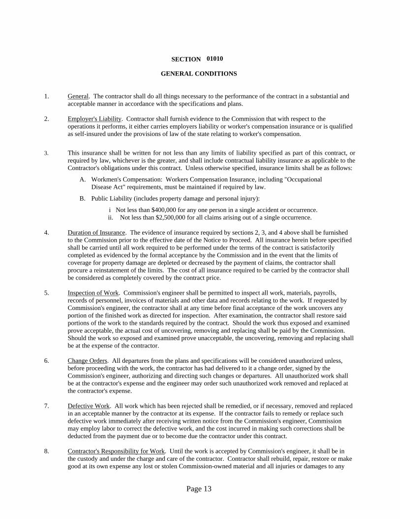
1. General. The contractor shall do all things necessary to the performance of the contract in a substantial and
acceptable manner in accordance with the specifications and plans. 2. Employer's Liability. Contractor shall furnish evidence to the Commission that with respect to the
operations it performs, it either carries employers liability or worker's compensation insurance or is qualified as self-insured under the provisions of law of the state relating to worker's compensation.
3. This insurance shall be written for not less than any limits of liability specified as part of this contract, or required by law, whichever is the greater, and shall include contractual liability insurance as applicable to the Contractor's obligations under this contract. Unless otherwise specified, insurance limits shall be as follows:
A. Workmen's Compensation: Workers Compensation Insurance, including "Occupational Disease Act" requirements, must be maintained if required by law.
B. Public Liability (includes property damage and personal injury):
i Not less than $400,000 for any one person in a single accident or occurrence. ii. Not less than $2,500,000 for all claims arising out of a single occurrence.
4. Duration of Insurance. The evidence of insurance required by sections 2, 3, and 4 above shall be furnished to the Commission prior to the effective date of the Notice to Proceed. All insurance herein before specified shall be carried until all work required to be performed under the terms of the contract is satisfactorily completed as evidenced by the formal acceptance by the Commission and in the event that the limits of coverage for property damage are depleted or decreased by the payment of claims, the contractor shall procure a reinstatement of the limits. The cost of all insurance required to be carried by the contractor shall be considered as completely covered by the contract price.
5. Inspection of Work. Commission's engineer shall be permitted to inspect all work, materials, payrolls,
records of personnel, invoices of materials and other data and records relating to the work. If requested by Commission's engineer, the contractor shall at any time before final acceptance of the work uncovers any portion of the finished work as directed for inspection. After examination, the contractor shall restore said portions of the work to the standards required by the contract. Should the work thus exposed and examined prove acceptable, the actual cost of uncovering, removing and replacing shall be paid by the Commission. Should the work so exposed and examined prove unacceptable, the uncovering, removing and replacing shall be at the expense of the contractor.
6. Change Orders. All departures from the plans and specifications will be considered unauthorized unless,
before proceeding with the work, the contractor has had delivered to it a change order, signed by the Commission's engineer, authorizing and directing such changes or departures. All unauthorized work shall be at the contractor's expense and the engineer may order such unauthorized work removed and replaced at the contractor's expense.
7. Defective Work. All work which has been rejected shall be remedied, or if necessary, removed and replaced
in an acceptable manner by the contractor at its expense. If the contractor fails to remedy or replace such defective work immediately after receiving written notice from the Commission's engineer, Commission may employ labor to correct the defective work, and the cost incurred in making such corrections shall be deducted from the payment due or to become due the contractor under this contract.
8. Contractor's Responsibility for Work. Until the work is accepted by Commission's engineer, it shall be in
the custody and under the charge and care of the contractor. Contractor shall rebuild, repair, restore or make good at its own expense any lost or stolen Commission-owned material and all injuries or damages to any
Page 13

portion of the work caused by action of the elements or from any other reason before its completion and final acceptance. Issuance of a payment estimate on any part of the work done will not be considered as final acceptance of any work completed up to that time.
9. Preservation of Utilities and Monuments. The contractor shall be responsible for the preservation of all
public and private utilities, wires, lines, pipes, poles, cables, and conduit at the site of the work and shall use every precaution necessary to prevent damage or injury thereto. The contractor shall not disturb or damage any land monument or property landmark until an authorized agent has witnessed or otherwise referenced, their location and shall not remove them until directed by Commission's engineer.
10. Cooperation with Other Contractors. The contractor shall arrange its work so as not to interfere with the
operations of other contractors of the Commission which might be engaged in performing adjacent or nearby work. Whenever work being done by other contractors is contiguous or related to the work involved in this contract, the respective rights of the various contractors will be determined by the Commission's engineer in order to secure the completion of the work under all contracts in general harmony.
11. Temporary Suspension of Work. Commission's engineer shall have authority to suspend work, wholly orin
part, for such period or periods of time as he may deem necessary when weather or other conditions are such that in the opinion of the engineer the work may be done at a later time with advantage to the Commission or for failure on the part of the contractor to comply with any of the provisions of the contract. The contractor may suspend work for reasonable cause with written approval of the engineer. Liquidated damages shall not accrue during the period in which work is suspended with the approval of the engineer, however, if the suspension is because of the contractor's failure to comply to any of the provisions of the contract, the contractor shall not be entitled to an extension of completion time nor to a waiver of liquidated damages. In the event work is suspended, the contractor shall store all materials in a manner that will protect them from damage, and shall take every precaution to prevent damage or deterioration of, the portions of the work completed. If work has been discontinued for any reason, the contractor shall give Commission's engineer written notice at least forty-eight (48) hours before resuming operations.
12. Contractor's Procedure for Claims. If the contractor considers additional compensation may be due for work
or material not clearly covered in the contract or ordered in writing by the engineer as extra work, or if additional compensation may be requested beyond the scope of such provisions, the contractor shall notify the engineer in writing of the intention to make a claim before beginning the work in question. If notification is not given and the engineer is not afforded proper facilities by contractor to provide necessary inspection and for keeping strict account of actual cost, the contractor agrees to waive any claims for additional compensation. Notice by the contractor, and the fact that the engineer has kept account of the cost shall not be construed as substantiating the validity of the claim. The contractor shall file a written notice of claim for additional compensation in triplicate within 60 days after completing the work in question.
If the claim is against the Commission, the notice of claim shall be personally delivered, or sent by certified mail to the office of the Secretary of the Commission in Jefferson City, Missouri. All notices of claims shall contain an itemized statement showing completely and fully the items and amounts forming the basis of the claim.
Any claim or an item of any claim, not included in the notice and statement, or any claim included but not clearly defined and specifically set out and itemized or any claim not filed within the time and in the manner provided, shall be forever waived and shall neither constitute the basis of nor be included in any legal action, counterclaim, set-off, or arbitration.
All claims filed with Missouri Highway and Transportation Commission's Secretary will be forwarded to the Missouri Department of Transportation's Claims Committee.
14. Overhead and Profit on Change Orders. The percentages for overhead and profit charged on Change Orders
and Field Work Authorizations shall be negotiated and may vary according to the nature, extent and complexity of the work involved. However, the overhead and profit for the contractor or subcontractor actually performing the work shall not exceed 15%. When one or more tiers of subcontractors are used, in
Page 14

no event shall any contractor or subcontractor receive as overhead and profit more than 7% of the cost of the work performed by any of his subcontractors. In no case shall the total overhead and profit paid by the owner on any change order exceed twenty five percent (25%) of the cost of materials, labor and equipment necessary to put the change order work in place.
15. Review of Submittals. The architect’s review of submittals is only for the limited purpose of checking for
conformance with information given and seeing if they conform to design intent. The architect is not responsible for determining the accuracy of measurements and completeness of details, for verifying quantities, or for checking fabrication or installation procedures. The architect’s review does not relieve the contractor of his or her responsibilities under the contract documents.
16. A working day. Is defined as any day when, soil and weather conditions would permit the major operation
of the project for six hours or more unless other unavoidable conditions prevent the contractor’s operation. If conditions require the contractor to stop work in less than six hours, the day will not be counted as a working day. Working days will begin as soon as notice to proceed is issued. In order for MoDOT not to change a work day due to unavoidable conditions, the contractor must have enough forces, equipment, and materials on site to begin the project. The contractor must notify MoDOT inspector before 12:00 noon of said working day if forces will not be present.
END OF SECTION
Page 15

01011
SUPPLEMENTARY CONDITIONS
SECTION
A. The following supplements modify, change, delete from or add to the "General Conditions." 1. The proposed work includes the furnishing of all materials, equipment and labor for the work as set
forth in the plans, proposal and specifications. 2. The contractor will be required to remove from the Highway and Transportation Commission's
property all debris. 3. The contractor will pay all sales and use taxes that constitute a legal obligation arising out of
this work. 4. The contract price shall include any necessary permits and licenses required by law incidental to the
work. Local ordinances requiring building permits are not applicable to the state. Contractor will comply with local laws involving safety in the prosecution of the work.
5. Contractor will provide a one year warranty for parts and labor on all building material, and
equipment or a standard manufacturer's warranty which ever is greater. All warranties, including extended service agreements shall begin on the date of Final Acceptance of this project.
6. The plans holders list may be obtained from the One Stop Facility located at 1320 Creek Trail
Drive, P.O. Box 270, Jefferson City, MO 65102, by calling 573/522-5591 or electronically down-loaded from http://www.modot.org/business/contractor_resources/FacilitiesConstructionandMaintenance.htm.
7. This project consists of two (2) entrances to the District Office with each entrance having an inner
and outer door system. The employee’s door entrance will have a proximity card reader controlling the operation of the outer door system. Pricing for connecting the card reader to this door system may be obtained by calling the contact listed below. The contractor will be responsible for the payment of this service, and will include the costs of this service in his/her bid.
Curt Stewart – VP Operations Security Innovations, Inc. 320 Brookes Drive, Suite 119 Hazelwood, MO 63042 314-731-1443 (Office) 314-731-1773 (Fax) 314-497-3271 (Mobile) B. DEFINITIONS 1. Architect: When the term "Architect" is used herein, it shall refer to Doug Record, (Building
Designer) or Jerrold Scarlett (Architect) Missouri Department of Transportation, General Services Division, (573) 526-7937, FAX (573) 526-6948.
2. Construction Inspector: When the term "Construction Inspector" is used herein, it shall refer to
Kevin Griep, Missouri Department of Transportation, General Services Division, (573) 526-4860, FAX (573) 526-6948.
END OF SECTION
Page 16
01019
CONTRACT CONSIDERATIONS
SECTIONSECTION
PART 1 GENERAL 1.1 SECTION INCLUDES A. Schedule of values. B. Application for payment. C. Change procedures. D. Alternatives. 1.2 RELATED SECTIONS A. Section 01600 - Material and Equipment: Product substitutions. 1.3 SCHEDULE OF VALUES
A. Submit a printed schedule on Contractor's standard form. Electronic media printout will be considered.
B. Submit Schedule of Values in duplicate within 20 days after date of Owner-Contractor Agreement. C. Revise schedule to list approved Change Orders, with each Application For Payment. 1.4 APPLICATIONS FOR PAYMENT A. Submit four copies of each application on Contractor's electronic media driven form. B. Content and Format: Utilize Schedule of Values for listing items in Application for Payment. C. Payment Period: 30 days. D. Submit waiver of liens from vendors. E. Include an updated construction progress schedule. F. Certified payroll records. 1.5 CHANGE PROCEDURES A. The Architect/Engineer may issue a Notice of Change that includes a detailed description of a
proposed change with supplementary or revised Drawings and specifications, a change in Contract Time for executing the change with a stipulation of any overtime work required.
B. The Contractor may propose changes by submitting a request for change to the Architect/Engineer, describing the proposed change and its full effect on the Work. Include a statement describing the reason for the change, the effect on the Contract Sum/Price and Contract Time, and a statement describing the effect on Work by the MoDOT District or other Contractors.
C. Stipulated Sum/Price Change Order: Based on Notice of Change and Contractor's fixed price quotation or Contractor's request for a Change Order as approved by Architect/Engineer.
D. Construction Change Directive: Architect/Engineer may issue a directive instructing the Contractor to proceed with a change in the Work, for subsequent inclusion in a Change Order. Document will describe changes in the Work, and designate method of determining any change in Contract Sum/Price or Contract Time. Promptly execute the change.
E. Time and Material Change Order: Submit itemized account and supporting data after completion of change, within time limits indicated in the Conditions of the Contract. Architect/Engineer will determine the change allowable in Contract Sum/Price and Contract Time as provided in the Contract Documents.
F. Maintain detailed records of work done on Time and Material basis. Provide full information required for evaluation of proposed changes, and to substantiate costs for changes in the Work.
G. Execution of Change Orders: Architect/Engineer will issue Change Orders for signatures of parties as provided in the Conditions of the Contract.
Page 17

1.6 DEFECT ASSESSMENT A. Replace the Work, or portions of the Work, not conforming to specified requirements.
B. If, in the opinion of the Architect/Engineer, it is not practical to remove and replace the Work, the Architect/Engineer will direct an appropriate remedy or adjust payment.
1.7 ALTERNATIVES A. Accepted Alternatives will be identified in Owner-Contractor Agreement.
END OF SECTION
Page 18

01039
COORDINATION AND MEETINGS
SECTION
PART 1 GENERAL 1.1 SECTION INCLUDES A. Coordination and project conditions. B. Field engineering. C. Preconstruction meeting. D. Site mobilization meeting. E. Progress meetings. F. Preinstallation meetings. G. Equipment electrical characteristics and components. H. Examination. I. Preparation. J. Cutting and Patching. K. Alteration project procedures. 1.2 COORDINATION AND PROJECT CONDITIONS A. Coordinate scheduling, submittals, and Work of the various sections of the Project Manual to
ensure efficient and orderly sequence of installation of interdependent construction elements. B. Verify utility requirements and characteristics of operating equipment are compatible with building
utilities. Coordinate work of various sections having interdependent responsibilities for installing, connecting to and placing in service, such equipment.
C. Coordinate space requirements, supports, and installation of mechanical and electrical Work, which are indicated diagrammatically on Drawings. Follow routing shown for pipes, ducts, and conduit, as closely as practicable; place runs parallel with lines of building. Utilize spaces efficiently to maximize accessibility for other installations, for maintenance, and for repairs.
D. In finished areas, except as otherwise indicated, conceal pipes, ducts and wiring within the construction. Coordinate locations of fixtures and outlets with finish elements.
E. Coordinate completion and clean up of Work of separate sections in preparation for Substantial Completion.
F. After Owner occupancy of premises, coordinate access to site for correction of defective Work and Work not in accordance with Contract Documents, to minimize disruption of Owner's activities.
1.3 FIELD ENGINEERING A. Employ a Land Surveyor registered in the State of Missouri and acceptable to Architect/Engineer. B. Owner will locate and protect survey control and reference points. C. Control datum for survey is that established by Owner provided survey. D. Verify set-backs and easements; confirm drawing dimensions and elevations. E. Provide field engineering services. Establish elevations, lines and levels, utilizing recognized
engineering survey practices. 1.4 PRECONSTRUCTION MEETING A. Architect/Engineer will schedule a meeting after Notice of Award. B. Attendance Required: District engineer or representative, Architect/Engineer and Contractor. C. Record minutes and distribute copies within 5 days after meeting to participants, with two copies to
District Engineer, Architect/Engineer, participants and those affected by decisions made.
Page 19

1.5 SITE MOBILIZATION MEETING A. Architect/Engineer will schedule a meeting at the Project site prior to Contractor occupancy. B. Record minutes and distributes copies within 5 days after meeting to participants, with two copies
to Architect/Engineer, participants and those affected by decisions made. 1.6 PROGRESS MEETINGS A. Schedule and administer meetings throughout progress of the Work at when arranged by
architect/engineer. B. Architect/Engineer will make arrangements for meetings, prepare agenda with copies for
participants, preside at meetings. C. Attendance Required: Job superintendent, major Subcontractors and suppliers, District engineer
representative, Architect/Engineer, as appropriate to agenda topics for each meeting. D. Agenda: 1. Review of Work progress. 2. Field observations, problems, and decisions. 3. Identification of problems, which impede planned progress. 4. Maintenance of progress schedule. 5. Corrective measures to regain projected schedules. 6. Coordination of projected progress. 7. Effect of proposed changes on progress schedule and coordination. E. Record minutes and distributes copies within 5 days after meeting to participants and those affected
by decisions made. 1.7 PREINSTALLATION MEETING A. When required in individual specification sections, convene a pre-installation meeting at the site
prior to commencing work of the section. B. Notify Architect/Engineer seven days in advance of meeting date. C. Prepare agenda and preside at meeting: 1. Review conditions of installation, preparation and installation procedures. 2. Review coordination with related work. D. Record minutes and distributes copies within 5 days after meeting to participants and those affected
by decisions made. PART 2 PRODUCTS Not used PART 3 EXECUTION 3.1 CUTTING AND PATCHING A. Employ skilled and experienced installer to perform cutting and patching. B. Submit written request in advance of cutting or altering elements, which affect: 1. Structural integrity of element. 2. Integrity of weather-exposed or moisture-resistant elements. 3. Work of Owner or separate contractor. C. Execute cutting, fitting, and patching to complete Work, and to: 1. Uncover Work to install or correct ill-timed Work. 2. Remove and replace defective and non-conforming Work.
3. Provide openings in elements of Work for penetrations of mechanical and electrical Work. D. Cut masonry and concrete materials using masonry saw or core drill. E. Fit Work tight to pipes, sleeves, ducts, conduit and other penetrations through surfaces. F. Maintain integrity of wall, ceiling, or floor construction; completely seal voids.
Page 20

G. Refinish surfaces to match adjacent finishes. For continuous surfaces, refinish to nearest intersection; for an assembly, refinish entire unit.
H. Identify hazardous substances or conditions exposed during the Work to the Architect/Engineer for decision or remedy.
3.2 ALTERATION PROJECT PROCEDURES A. Materials: As specified in Product sections; match existing Products and work for patching and
extending work. B. Close openings in exterior surfaces to protect existing work from weather and extremes of
temperature and humidity. C. When finished surfaces are cut so that a smooth transition with new Work is not possible, terminate
existing surface along a straight line at a natural line of division and submit recommendation to Architect/Engineer for review.
D. Patch or replace portions of existing surfaces that are damaged, lifted, discolored or showing other imperfections.
E. Finish surfaces as specified in individual Product sections.
END OF SECTION
Page 21

01300
SUBMITTALS
SECTION
PART 1 GENERAL 1.1 SECTION INCLUDES A. Submittal procedures. B. Construction progress schedules. C. Proposed Products list. D. Product Data. E. Shop Drawings. F. Samples. G. Design data. H. Test reports. I. Certificates. J. Manufacturer's instructions. K. Manufacturer's field reports. L. Erection drawings. 1.2 RELATED SECTIONS A. Section 01300 - Submittals B. Section 01400 - Quality Control: Manufacturers' field services and reports. C. Section 01700 - Contract Closeout: Contract warranties, bonds, manufacturers' certificates and
closeout submittals. 1.3 REFERENCES A. AGC Associated General Contractors of America publication "The Use of CPM in Construction - A
Manual for General Contractors and the Construction Industry". 1.4 SUBMITTAL PROCEDURES A. Transmit each submittal with Architect/Engineer accepted form. B. Identify Project, Contractor, Subcontractor or supplier; pertinent drawing and detail number and
specification section number, as appropriate. C. Apply Contractor's stamp, signed or initialed certifying that review, approval, verification of
Products required, field dimensions, adjacent construction Work and coordination of information is in accordance with the requirements of the Work and Contract Documents.
D. Schedule submittals to expedite the Project, and deliver to Architect/Engineer at business address. Coordinate submission of related items.
E. For each submittal for review, allow 15 days excluding delivery time to and from the contractor. F. Identify variations from Contract Documents and Product or system limitations, which may be
detrimental to successful performance of the completed Work. G. Submittals not requested will not be recognized or processed. 1.5 CONSTRUCTION PROGRESS SCHEDULES A. Submit initial schedule in duplicate within 15 days after date established in Notice to Proceed. B. Revise and resubmit as required. C. Submit revised schedules with each Application for Payment, identifying changes since previous
version. D. Submit a horizontal bar chart with separate line for each major portion of Work or operation,
identifying first workday of each week.
Page 22

1.6 PROPOSED PRODUCTS LIST A. Within 15 days after date of Notice to Proceed, submit list of major products proposed for use, with
name of manufacturer, trade name and model number of each product. B. For products specified only by reference standards, give manufacturer, trade name, model or
catalog designation and reference standards. 1.7 PRODUCT DATA A. Product Data For Review: 1. Submitted to Architect/Engineer for review for the limited purpose of checking for
conformance with information given and the design concept expressed in the contract documents.
2. After review, provide copies and distribute in accordance with SUBMITTAL PROCEDURES article above and for record documents purposes described in Section 01700 - CONTRACT CLOSEOUT.
B. Product Data For Information: 1. Submitted for the Architect/Engineer's knowledge as contract administrator or for the
Owner. C. Product Data For Project Close-out: 1. Submitted for the Owner's benefit during and after project completion. D. Submit the number of copies, which the Contractor requires, plus two copies that will be retained
by the Architect/Engineer. E. Mark each copy to identify applicable products, models, options and other data. Supplement
manufacturers' standard data to provide information specific to this Project. F. After review distribute in accordance with the Submittal Procedures article above and provide
copies for record documents described in Section 01700 - CONTRACT CLOSEOUT. 1.8 SHOP DRAWINGS A. Shop Drawings For Review: 1. Submitted to Architect/Engineer for review for the limited purpose of checking for
conformance with information given and the design concept expressed in the contract documents.
2. After review, produce copies and distribute in accordance with SUBMITTAL PROCEDURES article above and for record documents purposes described in Section 01700 - CONTRACT CLOSEOUT.
B. Shop Drawings For Information: 1. Submitted for the Architect/Engineer's knowledge as contract administrator or for the
Owner. C. Shop Drawings For Project Close-out: 1. Submitted for the Owner's benefit during and after project completion. D. Indicate special utility and electrical characteristics, utility connection requirements and location of
utility outlets for service for functional equipment and appliances. E. Submit in the form of one reproducible transparency and one opaque reproduction. 1.9 SAMPLES A. Samples For Review: 1. Submitted to Architect/Engineer for review for the limited purpose of checking for
conformance with information given and the design concept expressed in the contract documents.
2. After review, produce duplicates and distribute in accordance with SUBMITTAL PROCEDURES article above and for record documents purposes described in Section 01700 - CONTRACT CLOSEOUT.
Page 23

B. Samples For Information: 1. Submitted for the Architect/Engineer's knowledge as contract administrator or for the
Owner. C. Samples For Selection: 1. Submitted to Architect/Engineer for aesthetic, color, or finish selection. 2. Submit samples of finishes for Architect/Engineer selection. 3. After review, produce duplicates and distribute in accordance with SUBMITTAL
PROCEDURES article above and for record documents purposes described in Section 01700 - CONTRACT CLOSEOUT.
1.10 DESIGN DATA A. Submit for the Architect/Engineer's knowledge as contract administrator or for the Owner. B. Submit for information for the limited purpose of assessing conformance with information given
and the design concept expressed in the contract documents. 1.11 TEST REPORTS A. Submit for the Architect/Engineer's knowledge as contract administrator or for the Owner. B. Submit test reports for information for the limited purpose of assessing conformance with
information given and the design concept expressed in the contract documents. 1.12 CERTIFICATES A. When specified in individual specification sections, submit certification by the manufacturer,
installation/application subcontractor, or the Contractor to Architect/Engineer, in quantities specified for Product Data.
B. Indicate material or Product conforms to or exceeds specified requirements. Submit supporting reference data, affidavits and certifications as appropriate.
C. Certificates may be recent or previous test results on material or Product but must be acceptable to Architect/Engineer.
1.13 MANUFACTURER'S INSTRUCTIONS A. When specified in individual specification sections, submit printed instructions for delivery,
storage, assembly, installation, start-up, adjusting and finishing, to Architect/Engineer for delivery to owner in quantities specified for Product Data.
B. Indicate special procedures, perimeter conditions requiring special attention and special environmental criteria required for application or installation.
C. Refer to Section 01400 - Quality Control, Manufacturers' Field Services article. 1.14 MANUFACTURER'S FIELD REPORTS A. Submit reports for the Architect/Engineer's benefit as contract administrator or for the Owner. B. Submit for information for the limited purpose of assessing conformance with information given
and the design concept expressed in the contract documents. 1.15 ERECTION DRAWINGS A. Submit drawings for the Architect/Engineer's benefit as contract administrator or for the Owner. B. Submit for information for the limited purpose of assessing conformance with information given
and the design concept expressed in the contract documents. C. Data indicating inappropriate or unacceptable Work may be subject to action by the
Architect/Engineer or Owner.
END OF SECTION
Page 24

01400
QUALITY CONTROL
SECTION
PART 1 GENERAL 1.1 SECTION INCLUDES A. Quality assurance - control of installation. B. Tolerances C. References and standards. D. Mock-up. E. Inspecting and testing laboratory services. F. Manufacturers' field services. 1.2 RELATED SECTIONS A. Section 01300 - Submittals: Submission of manufacturers' instructions and certificates. B. Section 01600 - Material and Equipment: Requirements for material and product quality. C. Section 01650 - Starting of Systems. 1.3 QUALITY ASSURANCE - CONTROL OF INSTALLATION A. Monitor quality control over suppliers, manufacturers, Products, services, site conditions and
workmanship, to produce Work of specified quality. B. Comply with manufacturers' instructions, including each step in sequence. C. Should manufacturers' instructions conflict with Contract Documents, request clarification from
Architect/Engineer before proceeding. D. Comply with specified standards as minimum quality for the Work except where more stringent
tolerances, codes or specified requirements indicate higher standards or more precise workmanship. E. Perform Work by persons qualified to produce required and specified quality. F. Verify that field measurements are as indicated on shop drawings or as instructed by the
manufacturer. G. Secure Products in place with positive anchorage devices designed and sized to withstand stresses,
vibration, physical distortion, or disfigurement. 1.4 TOLERANCES A. Monitor fabrication and installation tolerance control of Products to produce acceptable Work. Do
not permit tolerances to accumulate. B. Comply with manufacturers' tolerances. Should manufacturers' tolerances conflict with Contract
Documents, request clarification from Architect/Engineer before proceeding. C. Adjust Products to appropriate dimensions; position before securing Products in place. 1.5 REFERENCES AND STANDARDS A. For Products or workmanship specified by association, trade or other consensus standards,
comply with requirements of the standard, except when more rigid requirements are specified or are required by applicable codes.
B. Conform to reference standard by date of issue current on date for receiving bids or date specified in the individual specification sections, except where a specific date is established by code.
C. Neither the contractual relationships, duties or responsibilities of the parties in Contract nor those of the Architect/Engineer shall be altered from the Contract Documents by mention or inference otherwise in any reference document.
Page 25

1.6 TESTING SERVICES A. Contractor to provide all testing services as called out in these specifications. B. Testing and source quality control may occur on or off the project site. Perform off-site testing as
required by the Architect/Engineer or the Owner. C. Testing does not relieve Contractor to perform Work to contract requirements. D. Re-testing required because of non-conformance to specified requirements shall be performed by
the same MoDOT personnel on instructions by the Architect/Engineer. 1.7 INSPECTION SERVICES A. Owner will employ MoDOT Personnel to perform inspection. B. Inspecting may occur on or off the project site. Perform off-site inspecting as required by the
Architect/Engineer or the Owner. C. Inspecting does not relieve Contractor to perform Work to contract requirements. 1.8 MANUFACTURERS' FIELD SERVICES A. When specified in individual specification sections, require material or Product suppliers or
manufacturers to provide qualified staff personnel to observe site conditions, conditions of surfaces and installation, quality of workmanship, start-up of equipment, test, adjust and the balancing of equipment as applicable and to initiate instructions when necessary.
B. Report observations and site decisions or instructions given to applicators or installers that are supplemental or contrary to manufacturers' written instructions.
C. Refer to Section 01300 - SUBMITTALS, MANUFACTURERS' FIELD REPORTS article. PART 2 EXECUTION 2.1 EXAMINATION A. Verify that existing site conditions and substrate surfaces are acceptable for subsequent
Work. Beginning new Work means acceptance of existing conditions. B. Verify that existing substrate is capable of structural support or attachment of new Work
being applied or attached. 2.2 PREPARATION A. Clean substrate surfaces prior to applying next material or substance. B. Seal cracks or openings of substrate prior to applying next material or substance. C. Apply manufacturer required or recommended substrate primer, sealer or conditioner prior to
applying any new material or substance in contact or bond.
END OF SECTION
Page 26
01500
CONSTRUCTION FACILITIES AND TEMPORARY CONTROLS
SECTION
PART 1 GENERAL 1.1 SECTION INCLUDES A. Temporary Utilities: Electricity, telephone service, facsimile service and sanitary facilities. B. Temporary Controls: enclosures and fencing, protection of the Work and water control. C. Construction Facilities: progress cleaning and temporary buildings. 1.2 TEMPORARY ELECTRICITY A. Cost: By Contractor; pay for temporary power service furnished by MoDOT. 1.3 TELEPHONE SERVICE A. Provide, maintain, and pay for telephone service to field office and Architect/Engineer's field office
at time of project mobilization. 1.4 FACSIMILE SERVICE A. Provide, maintain and pay for facsimile service and a dedicated telephone line to field office and
Architect/Engineer's field office at time of project mobilization. 1.5 TEMPORARY WATER SERVICE A. Connect to existing water source as directed for construction operations at time of project
mobilization. B. Contractor will reimburse Owner for water used in construction as agreed upon at time of project
mobilization. 1.6 TEMPORARY SANITARY FACILITIES A. Provide and maintain required facilities and enclosures. Provide at time of project mobilization. 1.7 FENCING A. Construction: Use plastic mesh safety fencing or better. B. Provide 48” high fence around construction site; equip with vehicular and pedestrian gates with
locks. 1.8 WATER CONTROL A. Grade site to drain. Maintain excavations free of water. Provide, operate and maintain pumping
equipment. B. Protect site from puddling or running water. Provide water barriers as required to protect site from
soil erosion. 1.9 EXTERIOR ENCLOSURES A. Provide temporary weather tight closure of exterior openings to accommodate acceptable working
conditions and protection for Products, to allow for temporary heating and maintenance of required ambient temperatures identified in individual specification sections, and to prevent entry of unauthorized persons. Provide access doors with self-closing hardware and locks.
Page 27

1.10 PROTECTION OF INSTALLED WORK A. Protect installed Work and provide special protection where specified in individual specification
sections. B. Provide temporary and removable protection for installed Products. Control activity in immediate
work area to prevent damage. C. Provide protective coverings at walls, projections, jambs, sills and soffits of openings. D. Protect finished floors, stairs, and other surfaces from traffic, dirt, wear, damage or movement of
heavy objects, by protecting with durable sheet materials. E. Prohibit traffic or storage upon waterproofed or roofed surfaces. If traffic or activity is necessary,
obtain recommendations for protection from waterproofing or roofing material manufacturer. F. Prohibit traffic from landscaped areas. 1.11 SECURITY A. Provide security and facilities to protect Work and existing facilities and Owner's operations from
unauthorized entry, vandalism or theft. B. Coordinate with Owner's security program. 1.12 ACCESS ROADS A. Provide and maintain access to fire hydrants, free of obstructions. B. Provide means of removing mud from vehicle wheels before entering streets. C. Designated existing on-site roads may be used for construction traffic. 1.13 PROGRESS CLEANING AND WASTE REMOVAL A. Maintain areas free of waste materials, debris and rubbish. Maintain site in a clean and orderly
condition. B. Remove debris and rubbish from pipe chases, plenums, attics, crawl spaces and other closed or
remote spaces, prior to enclosing the space. C. Broom and vacuum clean interior areas prior to start of surface finishing and continue cleaning to
eliminate dust. D. Collect and remove waste materials, debris and rubbish from site periodically and dispose off-site. E. Open free-fall chutes are not permitted. Terminate closed chutes into appropriate containers with
lids. 1.14 FIELD OFFICES AND SHEDS A. Office: Weather tight, with lighting, electrical outlets, heating and ventilating equipment and
equipped with drawing rack and drawing display table. B. Provide space for Project meetings, with table and chairs to accommodate 6 persons. 1.15 REMOVAL OF UTILITIES, FACILITIES, AND CONTROLS A. Remove temporary utilities, equipment, facilities and materials prior to Final Application for
Payment inspection. B. Clean and repair damage caused by installation or use of temporary work. C. Restore existing facilities used during construction to original condition. Restore permanent
facilities used during construction to specified condition.
END OF SECTION
Page 28
01600
MATERIAL AND EQUIPMENT
SECTION
PART 1 GENERAL 1.1 SECTION INCLUDES A. Products. B. Transportation and handling. C. Storage and protection. D. Product options. E. Substitutions. 1.2 RELATED SECTIONS A. Instructions to Bidders: Product options and substitution procedures. B. Section 01400 - Quality Control: Product quality monitoring. 1.3 PRODUCTS A. Do not use materials and equipment removed from existing premises, except as specifically
permitted by the Contract Documents. B. Provide interchangeable components of the same manufacture for components being replaced. 1.4 TRANSPORTATION AND HANDLING A. Transport and handle Products in accordance with manufacturer's instructions. B. Promptly inspect shipments to ensure that Products comply with requirements, quantities are
correct and products are undamaged. C. Provide equipment and personnel to handle Products by methods to prevent soiling, disfigurement
or damage. 1.5 STORAGE AND PROTECTION A. Store and protect Products in accordance with manufacturers' instructions. B. Store with seals and labels intact and legible. C. Store sensitive Products in weather tight, climate controlled, enclosures in an environment
favorable to Product. D. For exterior storage of fabricated Products, place on sloped supports above ground. E. Provide bonded off-site storage and protection when site does not permit on-site storage or
protection. F. Cover Products subject to deterioration with impervious sheet covering. Provide ventilation to
prevent condensation and degradation of Products. G. Store loose granular materials on solid flat surfaces in a well-drained area. Prevent mixing with
foreign matter. H. Provide equipment and personnel to store Products by methods to prevent soiling, disfigurement or
damage. I. Arrange storage of Products to permit access for inspection. Periodically inspect to verify Products
are undamaged and are maintained in acceptable condition. 1.6 PRODUCT OPTIONS A. Products Specified by Reference Standards or by Description Only: Any Product meeting those
standards or description is acceptable.
Page 29
B. Products Specified by Naming One or More Manufacturers: Products of manufacturers named and meeting specifications, no options or substitutions allowed.
C. Products Specified by Naming One or More Manufacturers with a Provision for Substitutions: Submit a request for substitution for any manufacturer not named in accordance with the following article.
1.7 SUBSTITUTIONS A. Architect/Engineer will consider requests for Substitutions only within 15 days after date
established in Notice to Proceed. B. Substitutions may be considered when a Product becomes unavailable through no fault of the
Contractor. C. Document each request with complete data substantiating compliance of proposed Substitution with
Contract Documents. D. A request constitutes a representation that the Contractor:
1. Has investigated proposed Product and determined that it meets or exceeds the quality level of the specified Product.
2. Will provide the same warranty for the Substitution as for the specified Product. 3. Will coordinate installation and make changes to other Work that may be required for the
Work to be complete with no additional cost to Owner. 4. Waives claims for additional costs or time extension that may subsequently become
apparent. 5. Will reimburse Owner for review or redesign services associated with re-approval by
authorities. E. Substitutions will not be considered when they are indicated or implied on shop drawing or product
data submittals, without separate written request or when acceptance will require revision to the Contract Documents.
F. Substitution Submittal Procedure: 1. Submit three copies of request for Substitution for consideration. Limit each request to
one proposed Substitution. 2. Submit shop drawings, product data and certified test results attesting to the proposed
Product equivalence. Burden of proof is on proposer. 3. The Architect/Engineer will notify Contractor in writing of decision to accept or reject
request. PART 2 PRODUCTS Not Used. PART 3 EXECUTION Not Used.
END OF SECTION
Page 30

01650
STARTING OF SYSTEMS
SECTION
PART 1 GENERAL 1.1 SECTION INCLUDES A. Starting systems. B. Demonstration and instructions. C. Testing, adjusting and balancing. 1.2 RELATED SECTIONS A. Section 01400 - Quality Control: Manufacturers field reports. B. Section 01700 - Contract Closeout: System operation and maintenance data and extra materials. 1.3 STARTING SYSTEMS A. Coordinate schedule for start-up of various equipment and systems. B. Notify Architect/Engineer seven days prior to start-up of each item. C. Verify that each piece of equipment or system has been checked for proper lubrication, drive
rotation, belt tension, control sequence and for conditions that may cause damage. D. Verify tests, meter readings, and specified electrical characteristics agree with those required by the
equipment or system manufacturer. E. Verify that wiring and support components for equipment are complete and tested. F. Execute start-up under supervision of applicable manufacturer's representative or Contractors'
personnel in accordance with manufacturers' instructions. G. When specified in individual specification Sections, require manufacturer to provide authorized
representative to be present at site to inspect, check and approve equipment or system installation prior to start-up and to supervise placing equipment or system in operation.
H. Submit a written report in accordance with Section 01300 that equipment or system has been properly installed and is functioning correctly.
1.4 DEMONSTRATION AND INSTRUCTIONS A. Demonstrate operation and maintenance of Products to Owner's personnel two weeks prior to date
of Final Completion. B. For equipment or systems requiring seasonal operation, perform demonstration for other season
within six months. C. Utilize operation and maintenance manuals as basis for instruction. Review contents of manual with
Owners' personnel in detail to explain all aspects of operation and maintenance. D. Demonstrate start-up, operation, control, adjustment, trouble-shooting, servicing, maintenance and
shutdown of each item of equipment at agreed time, at equipment location. E. Prepare and insert additional data in operations and maintenance manuals when the need for
additional data becomes apparent during instruction. F. The amount of time required for instruction on each item of equipment and system that’s specified
in individual sections.
END OF SECTION
Page 31

01700
CONTRACT CLOSEOUT
SECTION
PART 1 GENERAL 1.1 SECTION INCLUDES A. Closeout procedures. B. Final cleaning. C. Adjusting. D. Project record documents. E. Operation and maintenance data. F. Spare parts and maintenance Products. G. Warranties. 1.2 RELATED SECTIONS A. Section 01500 - Construction Facilities and Temporary Controls: Progress cleaning. B. Section 01650 - Starting of Systems: System start-up, testing, adjusting and balancing. 1.3 CLOSEOUT PROCEDURES A. Submit written certification that Contract Documents have been reviewed, Work has been
inspected, and that Work is complete in accordance with Contract Documents and ready for Architect/Engineer's review.
B. Provide submittals to Owner that is required by governing or other authorities. C. Submit final Application for Payment identifying total adjusted Contract Sum, previous payments
and sum remaining due. D. Owner will occupy portions of the building as specified in Section 01010. 1.4 FINAL CLEANING A. Execute final cleaning prior to final project assessment. Clean interior and exterior glass, surfaces
exposed to view; remove temporary labels, stains and foreign substances, polish transparent and glossy surfaces, vacuum carpeted and soft surfaces.
B. Clean equipment and fixtures to a sanitary condition with cleaning materials appropriate to the surface and material being cleaned.
C. Clean or replace filters of operating equipment used during construction and/or adjustment. D. Clean debris from roofs, gutters, downspouts and drainage systems. E. Clean site; sweep paved areas, rake clean landscaped surfaces. F. Remove waste and surplus materials, rubbish and construction facilities from the site. 1.5 ADJUSTING A. Adjust operating Products and equipment to ensure smooth and unhindered operation. 1.6 PROJECT RECORD DOCUMENTS A. Store record documents separate from documents used for construction. B. Record information concurrent with construction progress. C. Specifications: Legibly mark and record at each Product section description of actual Products
installed, including the following: 1. Manufacturer's name and product model and number. 2. Product substitutions or alternates utilized. 3. Changes made by Addenda and modifications.
Page 32

D. Record Drawings and Shop Drawings: Legibly mark each item to record actual construction
including: 1. Measured depths of foundations in relation to finish main floor datum. 2. Measured horizontal and vertical locations of underground utilities and appurtenances,
referenced to permanent surface improvements. 3. Measured locations of internal utilities and appurtenances concealed in construction,
referenced to visible and accessible features of the Work. 4. Field changes of dimension and detail. 5. Details not on original Contract drawings. E. Submit documents to Architect/Engineer with claim for final Application for Payment. 1.7 OPERATION AND MAINTENANCE DATA A. Submit data bound in 8-1/2 x 11 inch (A4) text pages, three D side ring binders with durable plastic
covers. B. Prepare binder cover with printed title "OPERATION AND MAINTENANCE INSTRUCTIONS",
title of project and subject matter of binder when multiple binders are required. C. Internally subdivide the binder contents with permanent page dividers, logically organized; with tab
titling clearly printed under reinforced laminated plastic tabs. D. Submit 1 draft copy of completed volumes 15 days prior to final inspection. This copy will be
reviewed and returned with Architect/Engineer comments. Revise content of all document sets as required prior to final submission.
E. Submit two sets of revised final volumes, within 10 days after final inspection. 1.8 SPARE PARTS AND MAINTENANCE PRODUCTS A. Provide spare parts, maintenance, and extra Products in quantities specified individual
specification sections. B. Deliver to Project site; obtain receipt prior to final payment. C. Examine system components at a frequency consistent with reliable operation. Clean, adjust and
lubricate as required. D. Include systematic examination, adjustment, and lubrication of components. Repair or replace parts
whenever required. Use parts produced by the manufacturer of the original component. E. Maintenance service shall not be assigned or transferred to any agent or Subcontractor without prior
written consent of the Owner. 1.9 WARRANTIES A. Execute and assemble transferable warranty documents from Subcontractors, suppliers and
manufacturers. B. Submit prior to final Application for Payment. C. For items of Work delayed beyond date of Final Completion, provide updated submittal within 10
days after acceptance, listing date of acceptance as start of the warranty period. PART 2 PRODUCTS Not Used. PART 3 EXECUTION Not Used.
END OF SECTION
Page 33

07900
JOINT SEALERS
SECTION
PART 1 GENERAL 1.1 SECTION INCLUDES A. Sealants and joint backing. 1.2 REFERENCES A. ASTM C834 - Standard Specification for Latex Sealing Compounds. B. ASTM C920 - Standard Specification for Elastomeric Joint Sealants. C. ASTM C1193 - Standard Guide for Use of Joint Sealants. 1.3 QUALITY ASSURANCE A. Manufacturer Qualifications: Company specializing in manufacturing the Products specified in this
section with minimum three years experience. B. Applicator Qualifications: Company specializing in performing the work of this section and
approved by manufacturer. 1.4 ENVIRONMENTAL REQUIREMENTS A. Maintain temperature and humidity recommended by the sealant manufacturer during and after
installation. 1.5 COORDINATION A. Section 01039 - Coordination and Meetings: Coordination requirements. B. Coordinate the work with all sections referencing this section. 1.6 WARRANTY A. Section 01700 - Warranties. B. Correct defective work within a five-year period after Date of Substantial Completion. C. Warranty: Include coverage for installed sealants and accessories which fail to achieve airtight seal
and exhibit loss of adhesion or cohesion or do not cure. PART 2 PRODUCTS 2.1 SEALANTS A. Type I - General Purpose Exterior Sealant: Polyurethane or Polysulfide; ASTM C920, Grade NS,
Class 25, Uses M, G and A; single or multi- component. 1. Standard colors matching finished surfaces.
Page 34

2.2 ACCESSORIES A. Primer: Non-staining type, recommended by sealant manufacturer to suit application. B. Joint Cleaner: Non-corrosive and non-staining type, recommended by sealant manufacturer;
compatible with joint forming materials. C. Joint Backing: Round foam rod compatible with sealant; ASTM D1056, sponge or expanded
rubber; oversized 30 to 50 percent larger than joint width. D. Bond Breaker: Pressure sensitive tape recommended by sealant manufacturer to suit application. PART 3 EXECUTION 3.1 EXAMINATION A. Verify that substrate surfaces and joint openings are ready to receive work. B. Verify that joint backing and release tapes are compatible with sealant. 3.2 PREPARATION A. Remove loose materials and foreign matter that might impair adhesion of sealant. B. Clean and prime joints in accordance with manufacturer's instructions. C. Perform preparation in accordance with manufacturer's instructions and ASTM C1193. D. Protect elements surrounding the work of this section from damage or disfiguration. 3.3 INSTALLATION A. Perform installation in accordance with sealant manufacturer's requirements for preparation of
surfaces and material installation instructions. B. Perform installation in accordance with ASTM C1193. C .Measure joint dimensions and size joint backers to achieve width-to-depth ratio, neck dimension,
and surface bond area as recommended by manufacturer, except where specific dimensions are indicated.
D. Install bond breaker where joint backing is not used. E. Install sealant free of air pockets, foreign embedded matter, ridges and sags. F. Apply sealant within recommended application temperature ranges. Consult manufacturer when
sealant cannot be applied within these temperature ranges. G. Tool joints concave. 3.4 CLEANING A. Clean adjacent soiled surfaces. 3.5 PROTECTION OF FINISHED WORK A. Protect sealants until cured.
END OF SECTION
Page 35

08460
AUTOMATIC SLIDING DOOR SYSTEM
SECTION
PART 1 GENERAL 1.1 SUMMARY:
A. Work included: furnishing and installing factory fabricated and finished automatic sliding door system(s). B. Related Sections:
1. Section 07900 – Joint Sealers 2. Section 08800 – Glazing 3. Section 16120 - Electrical Supply and Termination
1.2 REFERENCES:
A. Underwriters Laboratories (UL), 333 Pfingsten Road, Northbrook, IL 60062, 847-272-8800. B. American National Standards Institute (ANSI), 11 W. 42nd St., 13th Floor, New York, NY 10036, 212-642-
4900. C. Builders’ Hardware Manufacturers Association (BHMA), 355 Lexington Ave., New York, NY 10017, 212-
661-4261. D. National Fire Protection Association (NFPA), 1 Batterymarch Park, Quincy, MA 02269, 800-344-3555, 617-
770-3000. E. Canadian Standards Association (CSA), 178 Rexdale Blvd., Rexdale, ON, Canada M9W 1R3, 416-747-
4000. F. Boca Evaluation Services, 4051 West Flossmoor Road, Country Club Hills, IL 60478, 708-799-2305. G. ICBO Evaluation Services, 5360 Workman Mill Road, Whittier, CA 90601, 562-699-0543. H. International Standards Organization (ISO).
1.3 SUBMITTALS:
A. Product Data: Provide manufacturer’s product and complete installation data for all materials in this specification.
B. Shop drawings: Show profiles, joining method, location of components, anchorage details, adjacent construction interface, and dimensions as well as all necessary wiring and electrical requirements.
C. Samples: Sized to adequately represent material. D. Contract Closeout: Submit the Manufacturer’s warranty and performance certifications. E. Installation Guide: Provide a written installation guide and/or installation recommendations.
1.4 QUALITY ASSURANCE:
A. Automatic sliding door system shall be CERTIFIED by the manufacturer to meet performance design criteria according to the following test standards: 1. ANSI A156.10. 2. NFPA 101, Life Safety Code, section 5-2.1.9. 3. Underwriter’s Laboratories (UL) listed to UL325. 4. C-UL Certified (equivalent to CSA certified) to CSA 22-2 No. 247. 5. ICBO (UBC Standard 10-1). 6. BOCA (BOCA Code Section 1017.4.3). 7. American Society of Civil Engineers 7-98 8. ASTM test methods: E330-96, E283-91, E331-96, F842-97
B. Automatic Sliding Door System: Shall be manufactured in an ISO 9001 registered manufacturing facility.
Page 36

1.5 PRODUCT HANDLING:
A. All materials shall arrive in the manufacturer’s original sealed, labeled containers. B. Store material in a dry, protected, well-vented area. Report damaged material immediately to the delivering
carrier and note such damage on the carrier’s freight bill of lading. C. Remove all protective materials after installation.
1.6 SUBSTITUTIONS:
A. Proposals for substitution products will be accepted only from bidding contractors a minimum of 10 working days before the bid due date. The proposed substitution shall meet the performance and quality standards of this specification.
1.7 JOB CONDITIONS:
A. Verify that other trades are complete before installing the automatic sliding door system. B. Mounting surfaces shall be plumb, straight and secure; substrates shall be of proper dimension and material. C. Refer to the construction documents, shop drawings and manufacturer’s installation instructions. D. Coordinate installation with the glass, glazing and electrical work. E. Observe all appropriate OSHA safety guidelines for this work.
1.8 WARRANTY/GUARANTEE:
A. Manufacturer’s Standard Warranty: Warranted materials shall be free of defects in material and workmanship for one year after installation.
PART 2 PRODUCTS 2.1 MANUFACTURER:
A. Stanley Access Technologies 65 Scott Swamp Road Farmington, CT 06032 1-800-722-2377 Fax: 1-860-679-6436 Internet address - http://www.stanleyworks.com
B. Other manufacturers meeting these specifications. 2.2 AUTOMATIC SLIDING DOOR SYSTEMS:
A. Automatic Sliding Door System: Shall be equal to Stanley Bypass Door System. Each system shall consist of two sliding aluminum doors, fixed center panel, jambs, headers, operators, threshold tracks and actuating controls.
B. Sliding Aluminum Door Package: 1. Standard. Provide : standard narrow stile door panels. All doors shall have intermediate
rails. Bottom rails to be 8”. Dimension height to be 9’-11” with optional transom and width to be 11’-0”.
C. Sliding Aluminum Doors: Provide wind resistant gas dampers, for resistance to high wind when sliding panels are swung out into the direction of egress. In addition: 1. Standard. All door panels shall have security glass stops. Glass stops 1” shall be available
for all door panels and transom. The active sliding door panels shall include a single-point lock securing the lead edges of the sliding door stiles to the jamb. The active sliding door panels shall be provided with a key cylinder on the exterior and a thumb turn on the interior in accordance with NFPA 101.
Page 37

D. Door Operation: Shall be: 1. Standard. In compliance with NFPA 101, exterior sliding panel shall allow “breakout” to the full
open position to provide instant egress at any point in the door’s movement. The interior sliding door panel shall “breakout” in the direction of egress only at the full closed position
2. Door(s) shall be sized to prevent pinch points at overlapping stiles. E. Aluminum Frame and Extrusions: Shall be a minimum 0.125” wall thickness in integral structural sections.
The frame shall be standard 4 ½” deep section. F. Aluminum Extrusion Finish: Standard anodized finish shall be AA-M12-C22-A44 Dark Bronze. G. Stationary Center (“O”) Panel: Provide O-panel to dimension heights and widths as shown on construction
documents. All O-panels for Impact Option shall have one 4 ¼” intermediate rail and shall be steel-reinforced with a solid steel bar in each stile.
H. Header Case: Two provided. Shall be 6” wide by 8” high (152 mm wide by 203 mm high) extruded aluminum and capable of supporting of 220 pounds per leaf over a span of 18’4-1/2” with minimal deflection. It shall contain door operator and door mounting components. The header cover shall have a continuous self-locking hinge to open flush with the top of the header.
I. Door Hanger Wheels: Shall be 2 ½” (64 mm) diameter urethane wheels with precision steel lifetime lubricated ball bearing centers. The sliding door(s) shall be held on the track by 2” (51 mm) diameter anti-riser wheels and supported by a factory adjusted cantilever support and pivot assembly. This assembly shall allow the sliding doors to swing outward for emergency egress. The door height shall have an adjustment of ±1/8” as required by field conditions.
J. Threshold/Track: Two provided. Shall be recessed & continuous from jamb to jamb, 9” wide (2- 4 ½”). The threshold/track shall not be more than 1/2” in height. Raised thresholds more than 1/4” shall be beveled with slope not steeper than 1 in 2. (per NFPA 101 - 5-2.1.3).
K. Door Operator and Controller: Shall be equal to the Stanley Dura-Glide System driven by one electro-mechanical operator and a regulated electronic controller. The operator components shall consist of a DC permanent magnet 1/8 horsepower motor, gear reduction drive, Stanley Pozi-Trac position encoder, and a microprocessor control box. An electronic counter shall be installed in the header to count the number of open cycles. Customer to provide 120 VAC, 5 amps minimum to electrical door operator.
L. Microprocessor Control Box: Torque shall be factory set as prescribed by ANSI A156.10. The control box and Stanley Pozi-Trac position encoder shall automatically set the opening and closing check positions, and the full-open and full-closed position of the door system.
M. Threshold Sensor: Shall be field installed equal to Stanley Stanguard infrared threshold presence sensor. It shall be a self-contained, fully adjustable sensor system that works in conjunction with Stanley SU-100 motion sensors. Simultaneously with the door-opening signal, the sensor shall be energized. It shall emit a 30” deep by 72” maximum wide elliptical shaped infrared presence zone centered on the doorway threshold line. The door shall close after the SU-100 sensor and Stanley infrared threshold presence sensor detect a clear surveillance field.
N. Doorway holding beams: Shall be factory installed at a height of 13” per ANSI code A156.10. O. Motion Sensor: Shall be equal to the Stanley SU-100 Motion Sensor. The unit shall be switchable between
bi- directional and uni-directional K-band frequency to detect all motion, fast or slow, in both directions with a relay hold time of 1.5 - 30 seconds. The Stanley SU-100 shall be mounted to the header, 10’-0” maximum above the finish floor. Using the adjustable antenna the detection pattern shall be semi-circular, approximately 7’-0” wide by 5’-0” deep for a wide zone and approximately 6’-0” wide by 8’-0” deep for a narrow zone. The location of the detection zone shall be adjustable from the face of the door (20 degrees to 35 degrees in increments of 3 degrees). The unit shall operate between -30 degrees through 130 degrees Fahrenheit in all environmental conditions. The supply voltage shall be 12-24 V AC/DC +/- 10% and the power consumption shall be 6 W maximum.
P. Safety Search Circuitry: Shall be provided which will recycle the doors when an object is encountered during the closing cycle. The circuitry shall search for that object on the next closing cycle by reducing the door speed at the position the object was previously encountered, and will continue to close in check speed until the doors are fully closed, at which time the doors will reset to normal speed. If the obstruction is encountered again, the doors shall come to a full stop. The door shall remain stopped until the obstruction is removed and an operate signal is given, resetting the door to its normal speed.
Page 38

Q. Weatherstripping: Standard units shall have one and Impact Option shall have two adjustable nylon sweeps on the bottom of the sliding doors. Double pile weatherstripping shall be provided for the sliding door lead edges. Single pile weatherstripping shall be provided between the carrier and the header on the lead stiles of the O-Panel/P-Tube and the pivot stile(s) of the sliding door(s).
R. Accessories: The Bypass Door automatic sliding door system shall be supplied with a field-installed rotary switch to allow door(s) to open at full or reduced width according to weather and traffic conditions.
S. Motion sensor on exterior employee entrance door to work in conjunction with security card reader system. 2.3 OPERATING CONDITIONS:
A. Climatic Conditions: All automatic sliding door system components shall operate between -30 degrees and +130 degrees Fahrenheit, 95% relative humidity.
B. Performance Requirements: The header shall be capable of supporting bi-parting doors of 220 lbs per leaf over a span of 18’4-1/2” with a deflection not more than ¼". For Impact Option, the maximum allowable air infiltration rate is 1.2 cfm/ft2 in accordance with ASTM test methods.
PART 3 EXECUTION 3.1 INSPECTION:
A. Verify that the automatic sliding door system installation will not disrupt other trades. The door installer shall verify that the installation area is dry, clean and free of foreign matter. Check as-built conditions and verify the manufacturer’s automatic sliding entrance system details for accuracy to fit the wall assembly prior to fabrication. Report in writing to the Contractor any detrimental conditions to the proper functioning of the automatic sliding door system. Installation shall proceed once the unsatisfactory conditions have been corrected in accordance to the manufacturer’s recommendations.
3.2 INSTALLATION OF AUTOMATIC SLIDING ENTRANCE SYSTEMS:
A. Installation shall be by an installer approved and trained by the manufacturer in strict accordance with the manufacturer’s instructions and fire marshal listing requirements.
B. Comply with the automatic sliding door system manufacturer’s recommendations and/or installation guide when installing the automatic sliding door system. Set all units plumb, level and true.
C. Provide all fasteners required for installation of the automatic sliding door system. D. The owner will provide electric service, per door manufacturer’s specifications, to within 5’ of each door. E. Adjustment and Cleaning: After repeated operation of the completed installation, re-adjust door operators
and controls for optimum operating condition and safety. Clean all metal surfaces promptly after installation. F. Explain and review the Daily Safety Check Procedure.
END OF SECTION
Page 39

08800
GLAZING
SECTION
PART 1 GENERAL 1.1 SECTION INCLUDES
A. Flat glass materials. B. Insulating glass units. C. Glazing accessories.
1.2 RELATED SECTIONS
A. Section 08410 – Automatic Slide Doors. 1.3 REFERENCES A. ANSI Z97.1 – Standard Specification for Safety Performance Specifications and Methods of Test
for Safety Glazing Used in Buildings. B. ASTM C 162 – Standard Terminology of Glass and Glass Products.
B. ASTM C 804 – Standard Specification for Use of Solvent-Release Type Sealants. C. ASTM C 864 – Standard Specification for Dense Elastomeric Compression Seal Gaskets, Setting
Blocks, and Spacers. D. ASTM C 920 – Standard Specification for Elastomeric Joint Sealants. E. ASTM C1036 – Standard Specification for Flat Glass. F. ASTM C1048 – Standard Specification for Heat-Treated Flat Glass - Kind HS, Kind FT Coated and
Uncoated Glass. G. ASTM C 1193 – Standard Guide for Use of Joint Sealants. H. ASTM E 283 – Standard Test Method for Determining the Rate of Air Leakage Through Exterior
Windows, Curtain Walls, and Doors Under Specified Pressure Differences Across the Specimen. I. ASTM E 330 – Standard Test Method for Structural Performance of Exterior Windows, Curtain
Walls, and Doors by Uniform Static Air Pressure Difference. J. ASTM E 1300 – Standard Practice for Determining the Minimum Thickness and Type of Glass
Required to Resist a Specified Load. K. ASTM E 2188 – Standard Test Method for Insulating Glass Unit Performance. L. ASTM E 2189 – Standard Test Method for Testing Resistance to Fogging in Insulating Glass Units. M. ASTM E 2190 – Standard Specification for Insulating Glass Unit Performance and Evaluation. N. GANA (GM) – FGMA Glazing Manual; Glass Association of North America. O. GANA (SM) – FGMA Sealant Manual; Glass Association of North America.
1.4 DEFINITIONS
A. Sealed Insulating Glass Unit Surfaces. 1. Side 1 – Exterior surface of outer pane. 2. Side 2 – Interior surface of outer pane. 3. Side 3 – Interior surface of inner pane. 4. Side 4 – Exterior surface of inner pane.
1.5 SYSTEM DESCRIPTION
A. Size glass to withstand dead loads and positive and negative live loads acting normal to pane of glass in accordance with latest edition of IBC.
B. Limit glass deflection to l/200 or flexure limit of glass with full recovery of glazing materials, whichever is less.
Page 40

1.6 SUBMITTALS
A. Submit under provisions of Section 01300. B. Manufacturer’s data sheets on each product to be used, including:
1. Preparation instructions and recommendations. 2. Storage and handling requirements and recommendations. 3. Installation methods.
C. Verification Samples: 1. Flat Glass Materials: One 4 inch by 4 inch sample of each glass type specified. 2. Sealed Insulating Glass Units: One 12 inch by 12 inch sample representative of unit
construction. D. Certificates: Product certificates by the manufacturer certifying material compliance with specified
performance characteristics and criteria, and physical requirements. E. Warrant documents specified herein.
1.7 QUALIT ASSURANCE
A. Manufacturer Qualifications: Flat glass materials: Minimum five years documented experience producing glass products specified herein.
B. Fabricator, Sealed Insulating Glass Units: Minimum five years documented experience producing sealed insulating glass units specified in this section.
C. Installer Qualifications: Minimum five years documented experience installing products specified in this section, and approved by fabricatior.
1.8 DELIVERY, STORAGE, AND HANDLING
A. Store products in manufacturer’s unopened packaging until ready for installation. B. Store and dispose of solvent-based materials, and materials used with solvent-based materials, in
accordance with requirements of local authorities having jurisdiction. 1.9 PROJECT CONDITIONS
A. Maintain environmental conditions (temperature, humidity, and ventilation) within limits recommended by manufacturer for optimum results. Do not install products under environmental conditions outside manufacturer’s absolute limits.
B. Environmental Requirements: Installation of glass products at ambient air temperature below 50 degrees is prohibited.
C. Field Measurements: When construction schedule permits, verify field measurements with drawing dimensions prior to fabrication of glass products.
1.10 WARRANTY
A. Provide ten-year warranty to include replacement of sealed glass units exhibiting seal failure, interpane dusting or misting.
B. Provide ten-year warranty to include replacement for laminated glass exhibiting delamination. PART 2 PRODUCTS 2.1 MATERIALS
A. Clear Uncoated Float Glass: 1. Description: Annealed clear float glass meeting requirements of ASTM C 1036, Type 1,
Class 1, Quality q3. 2. Minimum Glass Thickness 5/16 inch.
Page 41
B. Tinted Uncoated Float Glass: 1. Description: Annealed tinted float glass meeting requirements of ASTM C 1036, Type 1,
Class 2, Quality q3. 2. Minimum Glass Thickness: 5/16 inch.
C. Setting Blocks: ASTM C 864, neoprene, 80 to 90 Shore A durometer hardness; length 4 inches, width of glazing rabbet space less 1/16 inch, height required for glazing method, pane weight, and pane area.
D. Spacer Shims: ASTM C 864, neoprene, 50 to 60 Shore A durometer hardness; length 3 inches, one half height of glazing stop, thickness required for application, one face self-adhesive.
E. Glazing Tape: Butyl compound tape with integral resilient tube spacer, 10 to 15 Shore A durometer hardness, black color, coiled on release paper; widths required for specified installation.
F. Glazing Tape: Closed cell polyvinyl chloride foam, maximum water absorption by volume 2%, designed for 25% compression percent for air barrier and vapor retarder seal, black color, coiled on relaeas paper over adhesive on two sides; widths required for specified installation.
G. Glazing Splines: ASTM C 864, resilient chloride, extruded shape to fit glazing channel retaining slot; black color.
H. Glazing Gaskets: ASTM C 864, resilient polyvinyl chloride, extruded shape to fit glazing channel retaining slot; black color.
I. Glazing Clips: Manufacturer’s standard type. J. Sealants: Specified in Section 07900.
2.1 FABRICATION
A. Heat Strengthened Glass: 1. Cut float glass material to required size and provide cut-outs and holes, if required, before
heat strengthening. 2. Heat strengthen float glass materials in accordance with ASTM C 1048, Kind HS.
B. Tempered Glass: 1. Cut float glass material to required size and provide cut-outs and holes, if required, before
heat strengthening. 2. Fully temper float glass materials in accordance with ASTM C 1048, Kind FT.
C. Sealed Insulating Glass Units: 1. Fabricate units in accordance with ASTM E 2190 Standard Specification for Insulating
Glass Units Performance and Evaluation with components and performance characteristics specified.
2. Insulating Glass Components: a. Outer Pane:
(1) Glass Type: Float Glass. (2) Glass Color:
(a) Exterior Units: Graylite 13. (b) Interior Units: Clear.
(3) Glass Thickness: 5/16 inch. (4) Heat Treating: Fully Tempered.
b. Inner Pane: (1) Glass Type: Float Glass. (2) Glass Color: Clear. (3) Glass Thickness: 5/16 inch. (4) Heat Treating: Heat Strengthened.
3. Provide edge seals meeting requirements of ASTM E 773, with aluminum spacers having mitered corners, and silicone sealant for glass-to-spacer seals.
Page 42

PART 3 EXECUTION 3.1 EXAMINATION
A. Verify that openings for glazing are correct size and within tolerance. B. Verify that glazing channels and recesses are clean and free of obstructions that weeps are clear and
channels and recesses are ready for glazing. 3.2 PREPARATION A. Clean contact surfaces to receive sealant with solvent and wipe dry. B. Seal porous glazing channels and recesses with substrate compatible primer or sealer. C. Prime surfaces scheduled to receive sealant in accordance with sealant manufacturer’s instructions. 3.3 INSTALLATION
A. Install in accordance with manufacturer’s instructions. B. Install sealant in accordance with ASTM C804 for solvent release sealants. C. Install sealant in accordance with sealant manufacturer’s instructions. D. Exterior Wet/dry Method (Formed Tape and Sealant):
1. Apply glazing tape to glass; butt-joint tape edges; seal joints with butyl sealant. 2. Apply glazing tape to permanent stops, ¼ inch below site line; butt-joint tape
edges; seal joints with butyl sealant. 3. Apply heel bead of butyl sealant along intersection of permanent stops with
frame; ensure full perimeter seal between glass and frame for continuity of air and vapor seal.
4. Place setting blocks with edge blocks maximum 6 inches from glass edges and intermediate blocks at ¼ points of glass length.
5. Set glass unit on setting blocks; apply pressure against fixed stop for full contact. 6. Install removable stops without displacing glazing tape; insert spacer strips
between glazing and applied stops; terminate spacer strips ¼ inch below sight line; apply pressure for full continuous contact.
7. Fill gap between glazing and stop with sealant to depth equal to bite of frame on glazing and to 3/8 inch below site line.
8. Apply cap bead of sealant along void between stop and glazing to uniform line flush with sight line; tool sealant surface smooth.
E. Interior Wet/dry Method (Tape and Sealant): 1. Apply glazing tape to glass; butt-joint tape edges; seal joints with butyl sealant. 2. Place setting blocks with edge blocks maximum 6 inches from glass edges and
intermediate blocks at ¼ points of glass length. 3. Set glass unit on setting blocks; apply pressure against fixed stop for full contact. 4. Install removable stops without displacing glazing tape; insert spacer strips
between glazing and applied stops; terminate spacer strips ¼ inch below sight line; apply pressure for full continuous contact.
5. Fill gap between glazing and stop with sealant to depth equal to bite of frame on glazing and to 3/8 inch below site line.
6. Trim sight-exposed tape flush with stop. 3.4 CLEANING A. Remove glazing materials from finish surfaces. B. Remove labels after glass installation is complete. C. Clean glass surfaces and adjacent surfaces.
Page 43

3.5 PROTECTION
A. Protect installed products until completion of project. B. Repair or replace damaged products before final completion.
END OF SECTION
Page 44

16100
ELECTRICAL WORK
SECTION
16101 GENERAL A. Requirements of the conditions of the contract and Instruction to Bidders, and General Conditions,
apply to all work of this Section. B. Provide complete electrical service as specified herein, and as needed for a complete and proper
installation of (4) automatic sliding doors including, but not necessarily limited to: 1. Branch circuit wiring, in conduit for junction boxes and motors. 2. Wiring system, in conduit, for equipment and control provided under other Sections of
these specifications. 3. Other items and services required to complete the system.
C. Related Work 1. Documents affecting work of this section include, but are not necessarily limited to,
General Conditions, Supplementary Conditions and Sections in Division 1 of these specifications
16102 FIELD CONDITIONS AND MEASURMENTS A. The Electrical Contractor shall visit the site of the work and familiarize himself with all available
information concerning the structural, excavations, the location condition bearing on transportation, handling, and storage of materials. The Electrical Contractor shall make his own estimate of the facilities needed, and difficulties of execution of the contract including local conditions, availability of labor, uncertainties of weather, transportation, and other contingencies. Failure of the contractor to acquaint himself with all available information concerning these conditions will not relieve him from responsibility for estimating the difficulties and costs or successfully performing the complete work.
16103 CLEANUP A. The Electrical Contractor shall have electrical rubbish and debris removed from the premises as
directed. On completion of the electrical contract all associated debris and rubbish shall be removed from the premises.
B. All electrical equipment and materials furnished by this contractor shall be thoroughly cleaned and ready for use upon completion of the work.
16104 GUARANTEE
A. Contractor guarantees by his acceptance of the contract, that all work installed shall be free from any defects in workmanship and/or materials and that all apparatus will develop capacities and characteristics specified and that if, during a period of one year or as therefore specified, from substantial completion of work, any such defects in workmanship, materials or performance appear, he will with no cost to owner remedy such defect.
16105 CODES A. All electrical work shall be done in strict accordance with the National Electrical Code and all
regulations, laws and ordinances that may be applicable.
Page 45

16106 QUALITY ASSURANCE A. Use adequate number of skilled workmen who are thoroughly trained and experienced in the crafts
and who are completely familiar with the specified requirements and the methods needed for proper performance of the work of this section.
B. Without additional cost to the owner, provide such other labor and materials as are required to complete the work of this section in accordance with the requirements of governmental agencies having jurisdiction, regardless of whether such materials and associated labor are called for elsewhere in these contract documents. 16107 CONDUIT
A. All interior wiring above grade shall be installed in electrical metallic tubing with screw coupling fittings.
B. Type MC cable with grounding conductor or type AC cable may be used for fixture whips. 16108 WIRE AND CABLE A. The minimum size conductor shall be as recommended by the automatic sliding door manufacturer. B. Conductors sized No. 10 and smaller shall be Type “THHN” solid or stranded as required unless
otherwise noted, sizes No. 8 and larger shall be type “THHN” stranded unless otherwise noted. C. Conductors shall be colored coded as required by governmental agencies having jurisdiction or as
required by the National Electrical Code. 16109 JUNCTION BOXES A. Junction or Pull Boxes 1. Interior junction boxes shall be galvanized code-gauge sheet steel units with screw-on
covers, of size and shape required to accommodate wires without crowding, and to suit the location.
2. Exterior boxes shall meet NEMA 3R or 4 standards. 16110 OTHER MATERIALS
A. Provide other materials, not specifically described but required for a complete and proper installation as approved by the Architect.
16111 EXECUTION A. Surface Conditions 1. Examine the areas and conditions under which work of this section will be performed.
Correct conditions detrimental to timely and proper completion of the work. Do not proceed until unsatisfactory conditions are corrected.
16112 PREPARATION A. Coordinate 1. Coordinate as necessary with other trades to assure proper and adequate provision in the
work of those trades for interface with the work of this section. 2. Coordinate the installation of electrical items with the schedule for work of other trades to
prevent unnecessary delays in the total work. B. Data indicated in these specifications are as exact as could be secured but there absolute accuracy is
not warranted. The exact locations, distances, levels and other conditions will be governed by actual construction and the specifications should be used only for guidance in such regard.
C. Verify all measurements at the building. No extra compensation will be allowed because of differences between work described and actual measurements at the site of construction.
Page 46

D. Branch circuit wiring and arrangement of home runs should be installed for maximum economy consistent with adequate sizing for voltage drops and other considerations.
16113 INSTALLATION OF RACEWAYS AND FITTINGS A. Where conduit is installed concealed in the walls or above the ceiling, or exposed in work areas,
provide rigid galvanized conduit or electrical metallic tubing with screw type fittings. B. Use flexible metal conduit only for short motor connections or where subject to vibration. C. Securely and rigidly support conduits throughout the work. Conduits and wiring above a ceiling
assembly shall not be supported to, or supported by, the ceiling assembly, including the ceiling support wires.
16114 INSTALLATION OF CONDUCTORS A. Unless otherwise recommended by the automatic sliding door manufacturer use #12 type THHN
conductors for all branch circuits protected by 20 amp circuit breakers. B. Use identified (white) neutrals and color-coded phase wires for all branch circuit wiring. 1. Make splices electrically and mechanically with pressure-type connectors. a. For wire size #6 AWG and smaller, provide “Scotch-Lock” connectors. 2. Insulate splices with a minimum of two half-lapped layers of Scotch Brand #33 vinyl-
plastic electrical tape where insulation is required. C. Tape all joints with rubber tape 1 1/2 times the thickness of the conductor insulation, than cover
with vinyl-plastic electrical tape specified above. 16115 TESTING AND INSPECTION A. Make required tests in the presence of the owners representative and required approvals from the
owner/architect and governmental agencies having jurisdiction. B. Make written notice to the owner/architect adequately in advance of each of the following stages of
construction. 1. When all rough in is complete, but not covered. 2. At completion of the work of this section.
C. When material and/or workmanship is found to not comply with the specified requirements, within three days after receipt of notice of such non-compliance remove the non-complying items from the job site and replace them with items complying with the specified requirements, all at no additional cost to the owner.
D. In the owner/architect’s presence: 1 Test all parts of the electrical systems for phase to phase and phase to ground short circuits
and prove that all such items provided under this section function electrically in the required manner.
2. Immediately submit to the architect a report of maximum and minimum voltages and a copy of the recording voltmeter chart.
3. Also measure voltages between phase wires and neutral and report these voltages to the Architect.
16116 PROJECT COMPLETION A. Upon completion of the work of this section, thoroughly clean all exposed portions of the electrical
installation, removing all traces of soil, labels, grease, oil, and other foreign material and using only the type cleaner recommended by the manufacturer of the item being cleaned.
B. Thoroughly indoctrinate the owner’s operation and maintenance personnel in the contents of the operations and maintenance manual required to be submitted under article 16106 of this section of these specifications.
END OF SECTION
Page 47