specifications for fabrication, erection, testing and ... · this work includes receipt of...
TRANSCRIPT

Specifications for fabrication, erection, testing a nd
Commissioning of Ductile iron, Carbon steel pipelin es (for road crossings) for Fire Protection system at FLP Complex
1. Introduction:
This specification is for Laying of underground Ductile Iron (DI) pipe lines for Fire protection (Hydrant) system including Fabrication and erection of Carbon steel (CS) pipes line at FLP Complex from Sub-station to old gas storage & fire pump room to LHFS at SDSC SHAR Centre, Sriharikota. The details are given in the layout drawings and Process & Instrumentation (P & I) diagrams.
2. Details of works and Scope of contract are as fo llows: Sl. No. Description Qty. Units
i. Erection of Socket and spigot type DI pipes and flow components like valves etc. 1m below ground level which includes providing required RCC pipe support saddles, Gaskets , fasteners excavation, testing, back filling and commissioning. Size: 300 NB
480 m
ii. Erection of Socket and spigot type DI pipes and flow components like valves etc. 1m below ground level which includes providing required RCC pipe support saddles, Gaskets and fasteners excavation, testing, back filling and commissioning. Size: 200 /250 NB
330 m
iii. Casting of RCC Thrust blocks as per approved drawings including excavation, reinforcement, Shuttering, casting, curing with RCC M-30 Grade & back filling
50 Cum
iv. Casting of valve chambers as per approved drawings including excavation, reinforcement, Shuttering, casting, curing with RCC M-30 Grade & back filling.
10 Cum
v. PCC for above thrust blocks & valve chambers with M-10 grade 20 Cum
vi. Carbon steel welding: Butt welding of pipes, fittings by GTAW welding process for Root and SMAW for subsequent passes with 10% Radiography for road crossings
420 Inch dia
vii. Carbon steel Socket welding of fittings, Slip on flanges etc by GTAW welding process for Root and SMAW for subsequent passes road crossings. 350 Inch dia
viii.
CS piping erection, Installation of flow components providing adequate clamping including providing supports in, Hume pipes ,Pipe trench concrete wall by using embedment plates / anchor fasteners where ever required , testing, painting tag numbering and commissioning.
750 Inch mtr
ix Wrapper coating of Carbon steel pipe line with 4mm thick AWWA C 203 tape, Size of Pipe: 300NB 100 mtr
x Wrapper coating of Carbon steel pipe line with 4mm thick AWWA C 203 tape, Size of Pipe: 200 NB 70 mtr

3. DETAILED SCOPE OF WORK :
Scope of work covered under this contract is excavation of earth to a depth of 1.0 m, laying of Ductile iron pipes on saddle supports, alignment, construction of thrust blocks, valve chambers, hydro testing and commissioning of Fire hydrant systems at FLP Complex. The scope of work also includes Fabrication, erection, testing and commissioning of carbon steel pipelines for road crossings and also for wrapping coating of Carbon steel pipe portion located below the earth.
• Ductile Iron pipelines as per IS: 8329, Class: K9 for underground Fire Hydrant system of sizes varying from 300NB to 200NB.
Sl.no. DESCRIPTION Approximate QTY, m
1 300NB 480
2 200/250NB 330
• Carbon steel pipelines (as per IS 3589/ IS 1239 and ASTM A106) for Fire protection system .Pipe sizes varying from 80 NB to 300NB.
Sl.no. DESCRIPTION Approximate QTY, inch m
1 300NB 504
2 200NB 192
3 150NB/100NB/80NB 54
• Structural steel fabrication works related to pipeline supports.
3.1 Ductile iron (DI) piping:
a. Laying of Ductile Iron pipeline of socket and spigot (Tyton) type laid on RCC pipe saddle blocks, inside excavated trench of suitable depth ensuring the following (length of each pipe is ~ 5.5 m). as per IS:12288 :
• Excavation to required depth.
• Minimum earth cover over the top of laid pipe shall be 1.0 m.
• For laying of Ductile Iron pipes of sizes 300 NB, 2 50NB, 200NBeach pipe shall be supported on 2 Nos. of RCC pipe support sa ddles (Saddle support Ref. Drg. No. FLP /SS/SB/01). The unit price quoted (in meters) for these items (i.e. indent Sl.no. 1&2) shall be inclusive o f these RCC saddle supports.
• It may be noted that pipe fittings are of flanged type requiring fasteners and Gaskets.(Schedule of flanged joints are given in Sl. no. 11.)
• Pipes shall be joined only by using proper mechanical tools like rack and lever arrangement, wire rope with turnbuckle etc.
• Suitable spacer pipe to be inserted in MJ collar, in order to avoid pipeline movement under pressure when up stream valve is kept in closed condition.

b. Leveling & alignment and installation of flow co mponents:
• Leveling & alignment for underground laid DI pipes as per IS:12288 / IS 3114 including installation of valves and construction of RCC thrust blocks & Valve chambers at appropriate locations. (For leveling & alignment instruments like Theodolite, Quick set leveling instrument shall be used).
• Installation of wafer type Butterfly valves.
• Installation of Hydrant landing Valves.
The unit price quoted for erection of piping system in meter basis considering Erection, installation of fabricated Hydrant and water monitor stand posts, pressure gauges etc., in the D.I pipe segments.
Schedule of items to be erected
Sl.No. Item description (Approx.) Qty. Nos. 1 Manual Butterfly valves
(Size: 300 NB - 7 Nos., 200NB - 8Nos) 18 Nos
c. RCC Thrust blocks, PCC platforms, Leveling of ea rth etc.:
• Construction of RCC thrust blocks for underground DI Pipeline. This includes excavation, back filling after casing the thrust block. (Refer Drg no: Drg. No. FLP/SS/TB/01 for BENDS typical thrust block & Drg. No. FLP/SS/TB/02 for TEE typical thrust block)
• Approximate number of thrust blocks is 7 Nos. (Refer layout drawing no. LSSF/SS/fire hydrant layout/FLP/01) and Thrust blocks typical drawings for location and details of thrust blocks for Tees, Bends. (Refer drawing No.s FLP/SS/TB/01 & FLP/SS/TB/02). Note: The quantity of RCC indicated in indent Sl.no. 03 is for the Thrust blocks only.
• Construction of RCC valve chambers for underground DI Pipeline. This includes
excavation,back filling after construction of valve chamber with water proof /impermeable RCC to prevent water entry into the valve chamber. (Refer Drg no: Drg. No. FLP/SS/VC/01 for valve chamber details).
• Partial re-filling of excavated earth, ensuring clear view of pipe joints for inspection during hydro testing.
• Hydro testing : Hydro testing of newly laid Fire water DI pipeline segments at 18
bar pressure and holding for 30minutes excluding observation time. • Interface jointing : Interface jointing of tested pipeline segments with existing
pipelines at the location indicated in layout drgs.
• Functional testing of integrated pipelines at Max. Operating pressure 12 bar for 24 hours.
• Refilling of excavated earth over hydro tested pipes and leveling including building up of earth over the thrust block wall for around 400 mm height.
• Leveling of earth disturbed for piping and related civil works as described above. • Erection CI markers as per enclosed sketch (As per Drg.No.FLP/SS/CI/01) along
newly laid pipelines (DI) at an interval of 30m.
• Boxing up and Commissioning: Fixing of Hydrants landing valves pressure gauges, Tag numbering, and painting etc.,
d. PRECAUTIONS TO BE FOLLOWED BY CONTRACTOR FOR DI PIPING WORK:
• Utmost care shall be taken while handling DI pipes & fittings loading at ISRO stores, & unloading at site and leading them to excavated trench.
• Pipes shall never be thrown, dropped or dragged while leading to trench.
• Pipes shall be lowered into the trench only with cotton / nylon ropes.
• All pipe ends shall be closed properly with plastic closures when not in use and prior to vacating the trench at the end of the day, in order to prevent rodent / sand entry. (Gunny bags are not allowed).
• It shall be ensured that pipe shall be properly seat on the RCC Saddle blocks/ pipe supports and properly aligned prior to joining.
• Pipes shall be joined only with proper mechanical tools like rack & lever, clamps & turn buckles etc. (Use of crow bar, hammer etc are not allowed as it is likely to damage the pipe and /or inner cement mortar lining).
� DI pipes shall be cut only with approved tools like hand/ power saw, grinders etc., Gas cutting shall not be attempted.
� While carrying out civil works like thrust blocks/ pipe supports and valve chambers, all fasteners, Isolation valves etc shall be duly protected from falling PCC debris. Construction activity shall be carefully planned in order not to damage nearby DI Pipes.
� While carrying out excavation & piping works, care shall be taken not to disturb/ damage existing earth fillings/ revetments etc, made to protect civil structures and roads. If unavoidable, after completion of work, such disturbed earth fill & revetments shall be rectified to original shape/ level.
� The present piping need to be integrated with the existing Fire protection system piping as per the details given in the drawing. (Ref. Drg.No. LSSF/SS/fire hydrant layout/FLP/01).

Note:
The supplier to refer Annexure – I for Sp ecification of DI Piping erection, construction of Thrust Blocks and Valve chambers.
3.2 Carbon Steel (CS) piping: 3.2.1 Fabrication and erection of CS pipelines (Butt-welding & Socket Welding)
This work includes receipt of requisite materials from stores, marking, cutting, profiling, aligning, fit up, Tack welding, cleaning, chipping, placement of wind shields and / or weather protection, DP testing of Root & Final Pass (Both Butt and Socket weld types), gamma Ray radiography (for 10% Butt weld joints).
• For Carbon steel pipes welding shall be by GTAW for root pass. The filler material used shall confirm to F-6 of ASME Section IX (70S2) and subsequent passes by manual metal arc welding (SMAW) with electrodes confirming to AWS classification E 7018.
• Only qualified welders to a level of 6G as per ASME Sec. IX with proven track record shall be deployed to carryout of the welding works. Qualification of welder need to be carried out in the presence of Department engineer suiting to the pipe size / schedule requirements. Fitters / Fabricators / Grinders should be well experienced. • Cutting and edge preparation of pipelines and fittings shall be attempted only with exclusive grinders meant for respective material (Carbon steel/ austenitic Stainless Steel).
• Wherever found necessary, mitre bends (4 pieces) shall be fabricated in place of regular elbows / bends.
3.2.1.1 Dye-Penetrant Test:
All welding joints shall be tested with Dye-Penetrant test after root pass and final pass welding for both Butt welding and Fillet / Socket welds of pipe line joints as per ASME Sec.- V.
3.2.1.2 Radiography:
a. All butt-welds shall be subjected to 10% Radiography (Carbon steel piping) Radiographic Examinations as per ASME sec. V for a sensitivity of 2-2T.
b. Interpretation of weld joints radiographs shall be done by Department representative as per relevant codes such ANSI B 31.3 and ASME-Sec.V
c. Exclusive radiography machine / Gamma ray source has to be arranged by the contractor.
d. D2 films shall be used for Gamma Rays and D5 films shall be used for X-rays. Elliptical shots (double wall double image) may be employed upto 2” size.
e. The penetrometer used shall conform to ASTM E 1025/ASTM E747 (or) relevant DIN standards.
f. Retake due to rejection of Radiograph owing to bad image quality shall at the cost of contractor.

g. Radiography shall be carried out by qualified technicians (i.e.) minimum level- I of ISNT/ ASNT and qualification certificates shall be produced with latest renewal to the Department before proceeding with the work.
h. Radiography film shall be evaluated and report shall be submitted by Level II ISNT/ ASNT (or) equivalent qualified person. However department Engineer will carry out the final Evaluation.
3.2.2 Carbon steel pipe erection
Erection of piping includes doubling of pipes, positioning of completed pipeline segments at required locations as per isometric drawings, piping layouts and instructions of department focal points depending on the site conditions. This work includes alignment of pipes & pipe fittings, maintenance of required slopes, proper fixing of flow components, pipe fittings & instruments and laying pipelines over structural pipe supports / RCC pedestals and Hume pipes in road crossings and also for hydrant landing valves/water monitors stand pipes and wrapping coating of CS pipe portion located below the earth. The unit price quoted for erection of piping system in inch. meter basis considering Erection, installation of valves, Hydrant landing valves/water monitors, pressure gauges etc., in the fabricated CS pipe segments, testing and commissioning. The work also includes integration of such pipelines with existing piping network/equipment including proper clamping of pipes on supports.
3.3 Wrapper coating :
Wrapper coating of buried CS pipe and CS pipes inside Hume pipe with 4 mm thick multi layer wrapper coating tapes as per AWWA C203. It may be noted that for hydrant stand posts/pipelines which will project above ground level, shall be protected by wrapper coating for the entire Carbon steel portion inside ground and upto 200 minimum from formed ground level.
3.4 Inspection:
a. Checking alignment of pipe line with Theodolite /Quickset leveling.
b. Check on tyton joints for ensuring proper insertion of spigot in the socket ends.
c. Check on reinforcement, casting, curing of thrust blocks and valve chambers.
d. Tightness of Flanged joints etc.
e. Inspection and clearance for pipe fit up, root DP, final Alignment checks etc. for CS piping.
f. Testing of RCC cube for strength periodically for thrust blocks, valve chambers & support saddles.
g. Hydro testing of pipelines loops.
h. Check on cleanliness of pipe line with thorough flushing.

3.5 Testing :
After satisfactory completion of fabrication and erection, Hydrostatic tests on completed piping segments as per ASTM A 530 at 18bar test pressure. Hydrostatic test shall be carried out with potable water. Sequence of Testing
• Flushing of piping segments. • Hydro testing of newly laid Fire water DI pipeline segments at Max. upto 18
bar pressure and holding time of 30 minutes excluding observation period. • Leak check with operating fluid of the total system as an integrated system
ready for process functional checks at operating pressure of 12 bar.
Note:
1. Carbon steel piping spools fabricated for road/rail crossings shall be hydro tested at 18bar and wrapper coated prior to positioning inside trench/below earth.
2. Hydro test set up: Valves, flanges, spool pieces etc., including Pump, Hose and etc., required for conducting Hydro Tests shall be mobilized by contractor.
4.0 Consumables:
The consumables such as Filler wires (ER 70S2), electrodes (E 7018 / E 6013), Grinding Wheels, Industrial Gases (Oxygen / Acetylene), Gas cutting set, Argon gas, Dye-Penetrant Test Kit, Argon regulator, Flow Meters, Face shields, Gloves, Wire Brush, Emery cloth, etc., required for the work shall be in the scope of contractor. Details of the consumables are as follows:
• Filler Wires: Size 1.6 mm / 2.0 mm / 2.5 mm, Make (Philips / ESAB / Advani). Manufacturers material test certificates shall be produced for approval.
• Electrodes: Size 2.5 mm / 3.15 mm Make (Philips / ESAB / Advani). Manufacturers material test certificates shall be produced for approval.
• Argon Gas cylinder & Oxy / Acetylene cylinders: Grade Commercial, Purity 99.99%, Cylinder Capacity 50 Ltrs, Make (Praxair / Bhoruka / Inox / BOC)
• Dye-Penetrant test Kit Containing cleaner / Penetrant / Developer, Make (Magnaflux / Check Mate)
• Grinding wheels: Make Universal carburandum/ Norton
• Oxy- Acetylene cylinders: Capacity: 50 Lit, Pressure 140-150 bar (g)

5.0 Manpower:
For carrying out above scope of work the contractor shall deploy three teams for DI pipe laying (One team shall contain minimum of 1 Plumber , 1 grinder ,1 Rigger and 3 helpers).and One team for CS piping and structural fabrication and (One team shall contain minimum of 1 welder, 1 fitter, 1 grinder and 2 helpers) depending on the availability of work front.
Adequate skilled, semi skilled manpower like 6G qualified TIG pipe welders, arc welders, fitter / fabricator, grinders, un-skilled helper gangs and site supervisor (Degree/Diploma in Mechanical Engg) with minimum 3-5 years experience carrying out similar Fabrication works & documentation shall also be deployed throughout the contract period. Category wise Manpower shall be indicated while quoting considering four teams engaged on an average throughout the contract period.
In case of urgent work demands the contractor shall mobilize additional welder/Helpers within 2-3 days.
6.0 Machinery: (Required for Four independent teams working simultaneously)
Requisite machinery like TIG welding machine, arc welding machine, grinders-angle/pencil, gas cutting sets and bench / hand drilling machines and concrete drillers, tube benders, pipe cutting machine ,Mechanical tools for DI piping like rack and lever, clamps & turn buckles etc. & hydro test pump, Theodolite (Quick set leveling instrument ) shall be mobilized by the contractor for the above scope of work. Minimum machinery required are Welding Machine (2Nos). Gas cutting Set with all accessories: 1 Nos, Grinding M/Cs : 2 Nos, Portable Hand drilling M/Cs : 2 Nos, Hydro test pump: 1 No., Concrete drilling Machine: 1 No. The above Machinery is minimum required. However contractor shall mobilize the required machinery as and when required.
7.0 Transportation & Material Handling: The contractor shall ensure:
• Receipt of pipes, pipe fittings, flow components etc., from stores, transportation to site and leading to work spot is in the scope of the contractor.
• Own Transport vehicles required for movement of contract personnel from /to work site and Gate I / Sullurpeta, including internal movement within site.
• Relevant derricks, hoists and fixtures for leading and positioning equipments on designated foundations including alignment tools.
• Department may provide material handling support on chargeable basis.
8.0 Electrical: o The contractor shall ensure Safe distribution of electrical power from single point source
identified by Department to various contractors’ utility points / equipment. The nearest power supply point will be 200-250 m from the actual work site in yard. Necessary cables have to be arranged by contractor along with Junction boxes, fuses, circuit breakers etc., as per the mandatory requirements of Department electrical safety.
9.0 The following are minimum requirements need to be ensured by contract agency:
9.1 Evaluation of Machinery and Manpower and Consum ables:
Machinery and manpower shall be subjected to technical evaluation by the Department Engineer to ascertain their complete suitability / performance for the jobs described above. Based on this evaluation clearance shall be given for taking up the actual job. Work shall be treated as commenced only when the actual welding work is done and as per various technical conditions detailed in this contract.
9.2 Medical Assistance:
While executing this service contract work, if any of the workers engaged by contract agency is injured, contract agency has to take care of medical treatment.
9.3 Documentation:
After awarding the contract: Contractor has to submit the following for approval
a. Work execution plan / PERT. And manpower deployment plan. i. Procedures for approval, D.I pipe line laying, thrust block. valve chamber construction (Radiography, hydro test , conditioning of Pipelines & painting, etc.)
ii. Monthly & weekly schedule.
b. During the execution of work: 1. Preparation of Material identification 2. Piping Alignment reports 2. Preparation of line and weld history sheets 3. Preparation of test packs and reports. 4. Preparation of as built drawings.
c. After commissioning (3 sets): 1. Submission of as built drawings. 2. Submission of final test dossier with neatly bounded condition.

10.0 Scope of Supply of Department:
• All piping materials (DI/CS) required for the execution of work such as pipes, pipe fittings,flanges, flow components like Butterfly valves of wafer type, Hydrant landing valves, FRP hose boxes, Hoses, hose fixing stand will be supplied by the Department as free issue material.
• Electricity required for machine tools like grinders, welding machine etc., (Will be
provided at the nearest available power point around 200-250m away.)
• Radiography source pit and dark room for development of films.
• Calibration of pressure gauges required for conducting hydro test.
11.0 SUPPLY OF MATERIAL UNDER CONTRACTOR’S SCOPE:
1. Electro galvanized Studs: As per IS 1364
i. Studs, nuts with lock nuts and washers for CS/DI pipe flanged joints, DI flanged fittings and Hydrant landing valves. (Make: Dev/ TVS/ Unbrako /Venkateswara) The details of CS & DI flanged joints are given in the following table.
SL.No.
Flanged joints/Size,NB(mm)
Approximate
Joints
QTY.Nos.
I. FOR DI PIPING
1 300NB 7
2. 200NB 2
II FOR CS PIPING
1 300NB 5
2 200NB 6
ii. Full/semi-threaded stud, nuts with locknuts and washers for installing wafer
type butterfly valves between flanges of sizes 200NB To 300NB (Make: Dev/ TVS/ Unbrako /Venkateswara) No. of valves for each size are given in the following table.
SL.No. Wafer type B/Fly valves size
Approximate
QTY.Nos.
1 300 NB 7
2 200 NB 8
2. Electro galvanized Anchor fasteners: Drilling and bolting as defined in the approved drawings. Drilling and anchoring of pipe supports, hangers and other wall / floor / roof embedment shall be carried out as required. Size of anchor fasteners required M12X150mm long, M12 x100mm long,M10X150mm long depending upon the site conditions. (Approximate quantity for each size will be about 200Nos.)
3. Gaskets ( Champion/ Spittman) as per IS 2712 to suit above mentioned flanges of material CAF Gr. W2 for flanged joints thickness 3mm.
4. Tyton Type Neoprene rubber gaskets (Die hard pol ymers) As per IS: 5382 for DI pipe joints for the pipe sizes and lengths as given in the table Sl.no. 02. (Approximate qty. 200NB – 65Nos & 300NB - 100Nos.)
5. Wrapper coating Material : Multi layer wrapper-coating tapes as per AWWA C203. Make: IWL (4 mm thick).
6. Hydro test set up: Valves, flanges, spool pieces, Pressure gauges etc., including Pump and Hose etc., required for conducting Hydro Tests. These materials can be taken back by vendor after successful completion of work.
7. Construction material (Reinforcement Steel, cement, Bricks, sand, Shuttering material etc.) required for civil works. 8. CI Markers as indicated in Drg. No: FLP/SS/CI/01 for fire water (Spacing between
markers shall be 30 m).
Note: Necessary manufacturers test reports (for material and qualification) shall be furnished for department scrutiny for GI fasteners, Gaskets, wrapper coat material, paints, Ductile iron pipe fittings etc. Check test has to be carried out in presence of Dept. personnel if asked for.
12.0 Payment terms: The following mile stone payments will be made on pro-rata basis on certification by Department focal point:
a. 75% payment after completion of fabrication, erection, construction of thrust blocks/valve chambers and completion of alignment checks.
b. 25% payment after completion of testing and commissioning. 13.0 General Conditions: 13.1 The Bidder shall quote their offer as “TWO- PART BID” (Technical & commercial)
13.2 Party evaluation:
• It is proposed to evaluate the supplier based on the previous experience in the fabrication and erection of DI piping / Carbon steel pipings and structural works. The contractor has to furnish/confirm the details as enclosed in the format-1.
• Tenderers / Contractors fulfilling the above conditions mentioned in format-1 only will be short listed for work.
• After receipt of quotation from the contractors, their credentials will be evaluated by the purchaser and their offers will be considered only after evaluation.
• As part of evaluation, contractor’s machinery and manpower shall be subjected to technical evaluation viz. Review of reports(PQR/ WPS, previous purchase orders &

welder qualification details), welder qualification, DP test, Radiography, Hydro /pneumatic testing and painting works, etc at the party’s location to ascertain their complete suitability for the jobs described above.
13.3 Sriharikota is an island and situated around 100 kms north of Chennai and the work
spot (FLP Complex) is located at about 12 kms from main entrance gate. Conveyance for Contractor personnel from and to work spot has to be arranged by the contractor
13.4 The contractor shall not employ persons below 18 years of age and no female labour shall be employed in dark hours. The contractor shall pay to each person, wages not less than minimum wages specified as per the labour laws.
13.5 Conveyance for contractor personnel from and to work spot has to be arranged by the contractor.
13.6 Department shall decide the hours of work on the site and the contractor shall adhere
to it. Department reserves the right to extend working hours beyond office hours including holidays based upon the progress of work to meet the work schedule/target.
13.7 Contractor shall take enough care to ensure to progress the work without any material
and personnel damage. It is the sole responsibility of contractor to ensure all safety norms to his personnel during transportation between work spot and Department/Contractor stores, and work in prefabrication area, in storage shed and in yard. Department will not hold responsibility to any mishap to the contractor personnel.
13.8 Free issue materials like pipes, specials, flow components, fittings and structural
material etc., issued by the Department shall be stored properly and in the event of any damage / loss to those items, the contractor shall replace the same at no cost or the cost of the material damaged shall be recovered from the running bills.
13.9 Department’s permission shall be obtained by contractor for establishing shed/ office
with an under taking for construction of shed with non- flammable material and for demolition of the same after completion of work.
13.10 The contractor shall be responsible for the safe storage of radiographic sources of his
sub-contractor. Radiographic source shall be stored in a room located at FLP complex which is about 10km from the work spot. However the transportation of source from the storage room to the work spot and back shall be the responsibility of the contractor.
13.11 The contractor shall give prior intimation to the Department whenever Radiography is
planned, and shall be carried out with necessary approvals only between 18:30 hrs to 06:30 hrs (06:30 PM to 06:30 AM) and the area shall be properly barricaded. However the contractor can take prior approval from the Department for carrying out Radiography during working hours i.e., from 09:00 hrs to 17:30 hrs.
13.12 Department will provide electricity required for the job, free of cost. However all
machinery required for above work like welding, grinding, drilling, cutting, etc., has to be arranged by contractor along with necessary Junction boxes, fuses, cables, hoses, etc.,

13.13 The contractor shall take prior approval from the Department for awarding sub-contract for full/partial works in the contract and the payment for the sub-contractor shall be the responsibility of the contractor.
13.14 The Department reserves the right to pay the sub-contractor directly from the running
bills in case if the contractor fails to pay his sub-contractor in the interest of completion of work.
13.15 Contractor has to give an undertaking that they will comply with prevailing safety
norms at site put forth by Department. Safety officer shall have full access to contractor’s storage shed. Office at any time for inspection.
13.16 The party shall give undertaking to hold the same q uoted unit prices for the
additional quantities of 10% of order quantities if site requirement calls for.
13.17 Period of contract /price validity:
- Period of contract: Twelve months from the date of clearance from department.
- Validity of contract: one year six months from the date of release of purchase of order.
Note:
- Contractor should mobilize all work force, machinery required within one month from date of P.O.
- Site clearance for commencement of work will be given within Two to Four months from the date of P.O
13.18 Progress review meetings once in a week will be conducted for monitoring the status of works and the contractor’s site representative need to attend with all relevant inputs.
13.19 As the all works are inter related, splitting of or der is not possible. Hence bidder shall quote for all items of this tender wit h out which offer will not be considered.
13.20 Purchaser reserves right to cancel the order at any stage if the performance of the contactor is not satisfactory and the contractor is not following stipulated Safety/security norms.
13.21 Contractor supervisor (Max. two) may be provided with hostel accommodation on chargeable basis depending on availability. Contractor has to arrange accommodation for their labourers outside the island.
13.22 The contractor shall clearly indicate deviations if any from indent specifications in the offer; otherwise to accept all the terms and conditions pu t by the department.
13.23 Item wise quantity format is only for indicating quantities of various items to be executed. Payment will be made by department for the actual quantity executed on Pro-Rata basis.

13.24 Security deposit: 10% value of the order shall be deposited with SDSC within 10 days from the date of the Purchase order towards security deposit in the form of Bank Guarantee towards performance of the Contract plus sixty days towards claim period. (This will be returned by SDSC immediately on execution of the order satisfactorily as per order terms. If not, the amount will be forfeited)
14.0 LIST OF DRAWINGS:
Sl. No. Drawing N o. Description
1 LSSF/SS/fire hydrant layout/FLP/01 Piping layout of Fire water Hydrant system to FLP
2 FLP/SS/SB/01 RCC support blocks for DI pipes. *
3 FLP/SS/TB/01 Typical Thrust Blocks for BENDS *
4 FLP/SS/TB/02 Typical Thrust Blocks for TEE * 5 FLP/SS/CS/01 Details of CS pipe laid below ground
inside Hume pipe 6 FLP/SS/CI/01 CI Markers for Fire water line
identification. 7 FLP/SS/VC/01 Typical RCC valve Chamber *
Note : * Typical drawings are given for thrust block, saddle support and valve chamber. Final construction drawings will be issued after awarding the contract prior to commencement of work
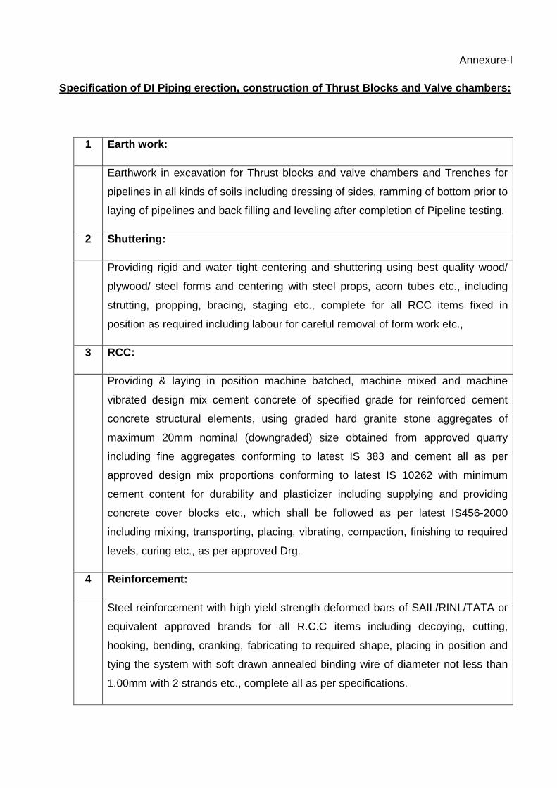
Annexure-I
Specification of DI Piping erection, construction o f Thrust Blocks and Valve chambers:
1 Earth work:
Earthwork in excavation for Thrust blocks and valve chambers and Trenches for
pipelines in all kinds of soils including dressing of sides, ramming of bottom prior to
laying of pipelines and back filling and leveling after completion of Pipeline testing.
2 Shuttering:
Providing rigid and water tight centering and shuttering using best quality wood/
plywood/ steel forms and centering with steel props, acorn tubes etc., including
strutting, propping, bracing, staging etc., complete for all RCC items fixed in
position as required including labour for careful removal of form work etc.,
3 RCC:
Providing & laying in position machine batched, machine mixed and machine
vibrated design mix cement concrete of specified grade for reinforced cement
concrete structural elements, using graded hard granite stone aggregates of
maximum 20mm nominal (downgraded) size obtained from approved quarry
including fine aggregates conforming to latest IS 383 and cement all as per
approved design mix proportions conforming to latest IS 10262 with minimum
cement content for durability and plasticizer including supplying and providing
concrete cover blocks etc., which shall be followed as per latest IS456-2000
including mixing, transporting, placing, vibrating, compaction, finishing to required
levels, curing etc., as per approved Drg.
4 Reinforcement:
Steel reinforcement with high yield strength deformed bars of SAIL/RINL/TATA or
equivalent approved brands for all R.C.C items including decoying, cutting,
hooking, bending, cranking, fabricating to required shape, placing in position and
tying the system with soft drawn annealed binding wire of diameter not less than
1.00mm with 2 strands etc., complete all as per specifications.

5 Plastering:
Water proof cement plastering of thickness as specified below in cement mortar
1:3 (1 cement : 3 coarse sand) mixed with approved water proofing compound
such as ROFFE HYPROOF manufactured by M/s Ruffle Construction Chemicals
Pvt. Ltd. at 140ml per bag of cement or CONPLAST X 421 IC of Forsook
Chemicals Ltd. at 130ml per bag of cement or equivalent approved make as per
manufacturers specifications including curing complete for Internal surfaces and
projected portion from ground level for external surface.
Annexure-II
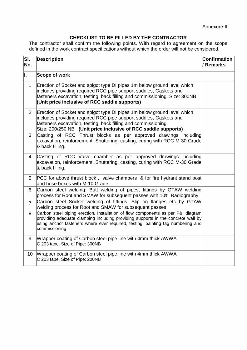
CHECKLIST TO BE FILLED BY THE CONTRACTOR The contractor shall confirm the following points. With regard to agreement on the scope defined in the work contract specifications without which the order will not be considered.
Sl. No.
Description Confirmation / Remarks
I. Scope of work
1 Erection of Socket and spigot type DI pipes 1m below ground level which includes providing required RCC pipe support saddles, Gaskets and fasteners excavation, testing, back filling and commissioning. Size: 300NB (Unit price inclusive of RCC saddle supports)
2 Erection of Socket and spigot type DI pipes 1m below ground level which includes providing required RCC pipe support saddles, Gaskets and fasteners excavation, testing, back filling and commissioning. Size: 200/250 NB (Unit price inclusive of RCC saddle supports)
3 Casting of RCC Thrust blocks as per approved drawings including excavation, reinforcement, Shuttering, casting, curing with RCC M-30 Grade & back filling.
4 Casting of RCC Valve chamber as per approved drawings including excavation, reinforcement, Shuttering, casting, curing with RCC M-30 Grade & back filling.
5 PCC for above thrust block , valve chambers & for fire hydrant stand post and hose boxes with M-10 Grade
6 Carbon steel welding: Butt welding of pipes, fittings by GTAW welding process for Root and SMAW for subsequent passes with 10% Radiography
7 Carbon steel Socket welding of fittings, Slip on flanges etc by GTAW welding process for Root and SMAW for subsequent passes
8 Carbon steel piping erection, Installation of flow components as per P&I diagram providing adequate clamping including providing supports in the concrete wall by using anchor fasteners where ever required, testing, painting tag numbering and commissioning
9 Wrapper coating of Carbon steel pipe line with 4mm thick AWWA C 203 tape, Size of Pipe: 300NB
10 Wrapper coating of Carbon steel pipe line with 4mm thick AWWA C 203 tape, Size of Pipe: 200NB

Sl.No Description of contr actor’s scope Confirmation / Remarks
II. Scope of Items under contractor’s scope
1. Consumables:
Filler Wires: Size 1.6 mm / 2.0 mm / 2.5 mm, Make (Philips / ESAB / Advani). Manufacturer’s material.
• Electrodes: Size 2.5 mm / 3.15 mm, Make ( Philips / ESAB / Advani).
• Argon Gas cylinder & Oxy / Acetylene cylinders: Grade Commercial, Purity 99.99%, Cylinder Capacity 50 Ltrs, Make (Praxair / Bhoruka / Inox / BOC)
• Dye-Penetrant test Kit Containing cleaner / Penetrant / Developer, Make (Magnaflux / Check Mate)
• Grinding wheels: Make Universal carburandum/ Norton
• Oxy- Acetylene cylinders: Capacity: 50 Lit, Pressure 140-150 bar (g)
• Electro galvanized Studs
(Make: Dev/TVS/ Unbrako /Venkateswara)
• Anchor fasteners Make : M/s HILTI
• Gaskets (Make: Champion/Spittman)
• Wrapper coating Material (Make: IWL)
• Tyton Type Neoprene rubber gaskets
(Make: Die hard polymers)
• Hydro test set up
• CI Markers
• Paints (Make:Berger/CDC carboline/Asian paints/Bombay paints/Goodlas Nerloa/Grand poly coats)
• Material for Thrust blocks, Platforms & pathways.

Sl. No. Description Confirmation
/ Remarks
2 Man power: - Three teams for DI pipe laying (One team shall contain
minimum of 1 Plumber ,1 grinder ,1 Rigger and 3 helpers.)
- One teams for CS piping fabrication.
(One team shall contain minimum of 1 Welder, 1 grinder, 1 fitter and 2 helpers.) Supervisor: 1 No.
3. Machinery: Minimum machinery required are Welding Machine: 3 Nos. .Gas cutting Set with all accessories: 2 Nos, Grinding M/Cs : 2 Nos, Portable Hand drilling M/Cs : 2 Nos, Hydro test pump: 1 No., Concrete drilling Machine: 2 Nos., pipe cutting machine, Mechanical tools for DI piping erection like rack and lever, Clamps & turn buckles etc, Theodolite/Quick set leveling instrument
4. Transportation & Material Handling: The contractor shall ensure:
• Own Transport vehicles required for movement of contract personnel to site.
• Material handling support for pipes transportation from department stores which is about 4-5 km to Work spot will be arranged by Department on chargeable basis and subjected to availability.
• Handling of pipes in yard and placing pipes on RCC pedestals, pipe supports in trenches and inside SVAB after fabrication is in the scope of contractor.
•
5. Electrical: The contractor shall ensure Safe distribution of electrical power from single point source identified by Department to various contractors’ utility points / equipment. The nearest power supply point will be 200-250 m from the actual work site in yard. Necessary cables have to be arranged by contractor along with Junction boxes, fuses, circuit breakers etc., as per the mandatory requirements of Department electrical safety.
Sl. No. Description Confirmation / Remarks
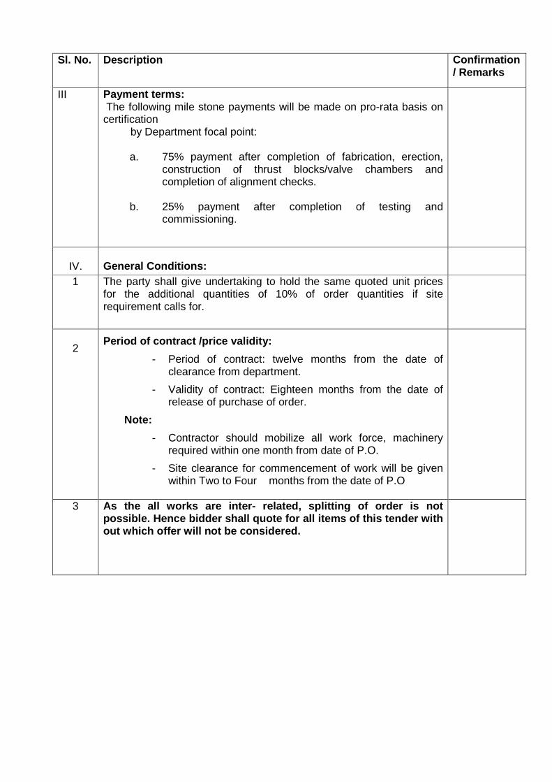
III Payment terms: The following mile stone payments will be made on pro-rata basis on certification by Department focal point:
a. 75% payment after completion of fabrication, erection, construction of thrust blocks/valve chambers and completion of alignment checks.
b. 25% payment after completion of testing and commissioning.
IV.
General Conditions:
1 The party shall give undertaking to hold the same quoted unit prices for the additional quantities of 10% of order quantities if site requirement calls for.
2
Period of contract /price validity:
- Period of contract: twelve months from the date of clearance from department.
- Validity of contract: Eighteen months from the date of release of purchase of order.
Note:
- Contractor should mobilize all work force, machinery required within one month from date of P.O.
- Site clearance for commencement of work will be given within Two to Four months from the date of P.O
3 As the all works are inter - related, splitting of order is not possible. Hence bidder shall quote for all items of this tender with out which offer will not be considered.

(Format: 1)
Mandatory Checklist to be filled and submitted for bid evaluation:-
Vendor shall fill the following checklist and submit with the offer. Deviation from
point wise confirmation shall be spelt out clearly.
Sl. No
Description To be filled by the Supplier
Remarks
A The contractor who is in the line of fabrication and erection of DI piping & CS piping shall only need to participate in the Tender
B Machinery Details
B.1 No. of portable TIG welding machines with necessary accessories including its make
B.2 No. of Gas cutting set with necessary accessories
B.3 No. of Grinding machine including its make
B.4 No. of tube benders /pipe bending machines , pipe cutting machine including its make
B.5 Mechanical tools for DI piping erection like rack and lever, Clamps & turn buckles etc, Theodolite/Quick set leveling instrument
B.6 Hydro test pump
B.7 No. of Portable Hand drilling machine including its make
C
Manpower Details
Manpower to be deployed as per tender specifications Sl.No. 5
Documentary Evidence Regarding welders qualification shall be furnished
D Company profile & experience
D.1 Work orders executed related to Fabrication and erection of DI Pipe lines CS pipe lines and MS Structures.(Value more than 30.0 lakhs)
Documentary Evidence previous work orders/ purchase orders shall be furnished last 2 years
D.2 Experience in Fabrication and erection of DI / CS Pipe lines and MS Structures
D.3 Experienced & qualified supervisors to execute the job as detailed in our tender specification
D.4 Enclose Company Registration detail
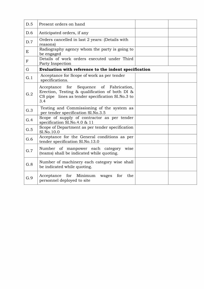
D.5 Present orders on hand
D.6 Anticipated orders, if any
D.7 Orders cancelled in last 2 years: (Details with reasons)
E Radiography agency whom the party is going to be engaged
F Details of work orders executed under Third Party Inspection
G Evaluation with reference to the indent specification
G.1 Acceptance for Scope of work as per tender specifications.
G.2
Acceptance for Sequence of Fabrication, Erection, Testing & qualification of both DI & CS pipe lines as tender specification Sl.No.3 to 3.4
G.3 Testing and Commissioning of the system as per tender specification Sl.No.3.5
G.4 Scope of supply of contractor as per tender specification Sl.No.4.0 & 11
G.5 Scope of Department as per tender specification Sl.No.10.0
G.6 Acceptance for the General conditions as per tender specification Sl.No.13.0
G.7 Number of manpower each category wise (teams) shall be indicated while quoting.
G.8 Number of machinery each category wise shall be indicated while quoting.
G.9 Acceptance for Minimum wages for the personnel deployed to site