specification - taoglas · specification part no. : ma1060.a.lbct.001 ... improved am/fm radio...
TRANSCRIPT
SPE-16-8-071/C Page 1 of 40
SPECIFICATION
Part No. : MA1060.A.LBCT.001
Product Name : Raptor I MA1060 Sharkfin
4in1 Next Generation
Permanent Mount External Antenna
with LTE, GNSS, Wi-Fi and AM/FM
Features : High Efficiency
Omnidirectional
4G/3G/2G Antenna
698~960MHz, 1710~2170MHz, 2300~2700MHz
GPS/GLONASS/GALILEO/BeiDou L1 Antenna
1561/1575.42/1602MHz
Wi-Fi Antenna 2.4GHz/5.8GHz Antenna
AM/FM Antenna
IP67 Waterproof
SMA(M) connector (Fakra optional)
RG-316 30cm length
Cable Length and Connectors Customizable
RoHS Compliant
SPE-16-8-071/C Page 2 of 40
1. Introduction
The Raptor I MA1060.A Sharkfin antenna is a next generation 4in1, vehicle roof
permanent mount solution. Fully IP67 waterproof, it has a distinctive high quality,
glossy and robust ABS+PC housing. A hardened polished finish is used according to
the strictest OEM automotive standards.
The Raptor I supports GNSS (GPS/GLONASS/GALILEO/BeiDou), Wi-Fi (2.4/5.8GHz),
LTE (4G/3G/2G) and a powered AM/FM radio. This sleek antenna is first tier
TS16949 automotive approved and is an ideal choice for:
• OEM automotive
• Trucks
• Other vehicles and heavy equipment
• General Telematics
The antenna comes with 30cm RG-316 coaxial pigtail cables as standard,
terminating in SMA(M) for GNSS, LTE and AM/FM and with RP SMA(M) for Wi-Fi.
The LTE antenna provides highest efficiency on all common worldwide LTE bands
and also works great if the system falls back to 3G and 2G as it also covers these
cellular bands.
The AM/FM antenna has an in-built amplifier to increase receive signal sensitivity.
The antenna works in conjunction with a 12v DC power source to ensure that
improved AM/FM radio signals are delivered to the audio system via an SMA(M)
connector.
The antennas inside can be completely customized according to requirements, to
work on other applications, such as ISM bands or DSRC. Where more than 4
antennas are needed, we recommend the Raptor II, which can combine 6 antennas
in one housing due to its dual-fin design.
SPE-16-8-071/C Page 3 of 40
Cable length and connector types are customizable. Gain and efficiency depend on
cable length. Peak gain will be lower with longer cable lengths. Use of low loss
CFD200 cable extensions is recommended but higher loss RG316 can be used up to
approximately 1 meter without significant impact on performance.
The Taoglas Raptor antenna series is manufactured in TS16949 automotive
approved facilities. Contact your regional Taoglas Sales office for support.
SPE-16-8-071/C Page 4 of 40
2. Specifications
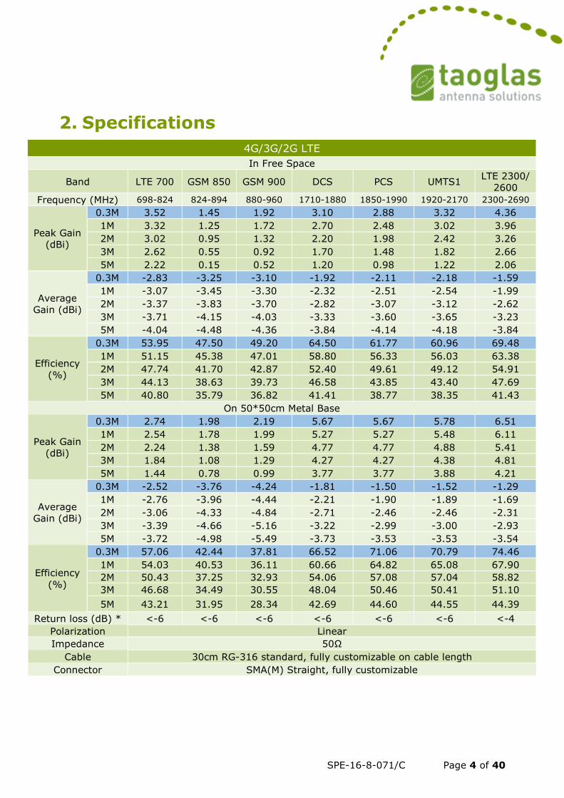
4G/3G/2G LTE
In Free Space
Band LTE 700 GSM 850 GSM 900 DCS PCS UMTS1 LTE 2300/
2600
Frequency (MHz) 698-824 824-894 880-960 1710-1880 1850-1990 1920-2170 2300-2690
Peak Gain
(dBi)
0.3M 3.52 1.45 1.92 3.10 2.88 3.32 4.36
1M 3.32 1.25 1.72 2.70 2.48 3.02 3.96
2M 3.02 0.95 1.32 2.20 1.98 2.42 3.26
3M 2.62 0.55 0.92 1.70 1.48 1.82 2.66
5M 2.22 0.15 0.52 1.20 0.98 1.22 2.06
Average
Gain (dBi)
0.3M -2.83 -3.25 -3.10 -1.92 -2.11 -2.18 -1.59
1M -3.07 -3.45 -3.30 -2.32 -2.51 -2.54 -1.99
2M -3.37 -3.83 -3.70 -2.82 -3.07 -3.12 -2.62
3M -3.71 -4.15 -4.03 -3.33 -3.60 -3.65 -3.23
5M -4.04 -4.48 -4.36 -3.84 -4.14 -4.18 -3.84
Efficiency
(%)
0.3M 53.95 47.50 49.20 64.50 61.77 60.96 69.48
1M 51.15 45.38 47.01 58.80 56.33 56.03 63.38
2M 47.74 41.70 42.87 52.40 49.61 49.12 54.91
3M 44.13 38.63 39.73 46.58 43.85 43.40 47.69
5M 40.80 35.79 36.82 41.41 38.77 38.35 41.43
On 50*50cm Metal Base
Peak Gain
(dBi)
0.3M 2.74 1.98 2.19 5.67 5.67 5.78 6.51
1M 2.54 1.78 1.99 5.27 5.27 5.48 6.11
2M 2.24 1.38 1.59 4.77 4.77 4.88 5.41
3M 1.84 1.08 1.29 4.27 4.27 4.38 4.81
5M 1.44 0.78 0.99 3.77 3.77 3.88 4.21
Average
Gain (dBi)
0.3M -2.52 -3.76 -4.24 -1.81 -1.50 -1.52 -1.29
1M -2.76 -3.96 -4.44 -2.21 -1.90 -1.89 -1.69
2M -3.06 -4.33 -4.84 -2.71 -2.46 -2.46 -2.31
3M -3.39 -4.66 -5.16 -3.22 -2.99 -3.00 -2.93
5M -3.72 -4.98 -5.49 -3.73 -3.53 -3.53 -3.54
Efficiency
(%)
0.3M 57.06 42.44 37.81 66.52 71.06 70.79 74.46
1M 54.03 40.53 36.11 60.66 64.82 65.08 67.90
2M 50.43 37.25 32.93 54.06 57.08 57.04 58.82
3M 46.68 34.49 30.55 48.04 50.46 50.41 51.10
5M 43.21 31.95 28.34 42.69 44.60 44.55 44.39
Return loss (dB) * <-6 <-6 <-6 <-6 <-6 <-6 <-4
Polarization Linear
Impedance 50Ω
Cable 30cm RG-316 standard, fully customizable on cable length
Connector SMA(M) Straight, fully customizable
SPE-16-8-071/C Page 5 of 40
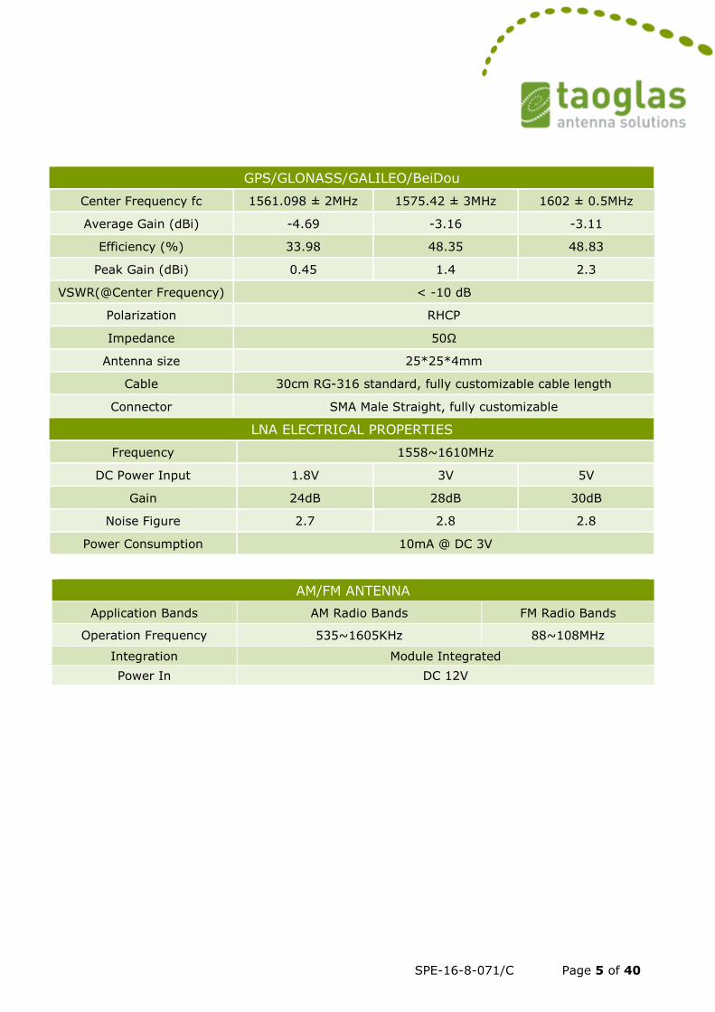
GPS/GLONASS/GALILEO/BeiDou
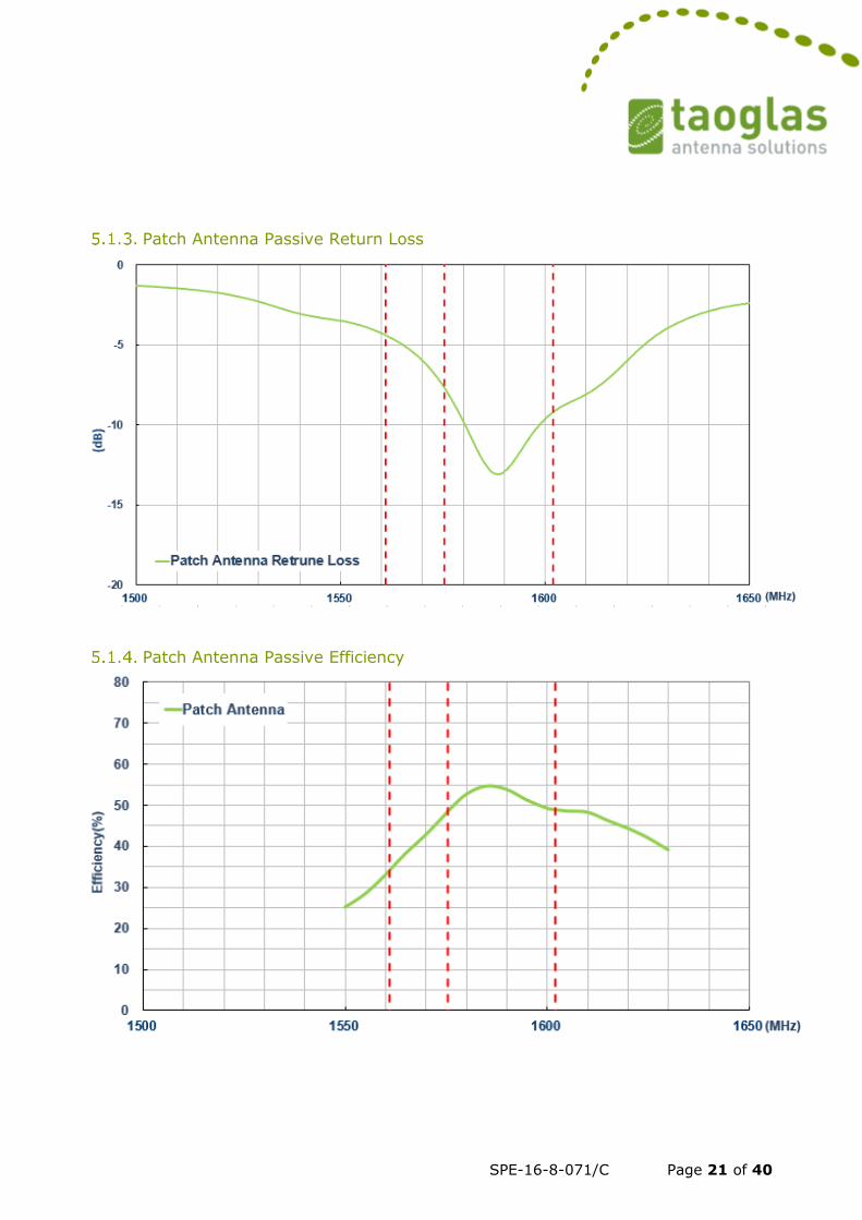
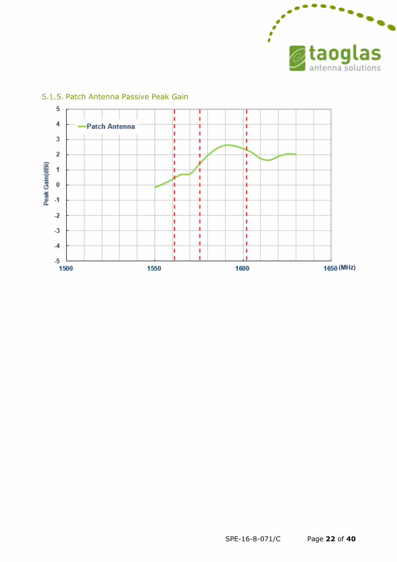
Center Frequency fc 1561.098 ± 2MHz 1575.42 ± 3MHz 1602 ± 0.5MHz
Average Gain (dBi) -4.69 -3.16 -3.11
Efficiency (%) 33.98 48.35 48.83
Peak Gain (dBi) 0.45 1.4 2.3
VSWR(@Center Frequency) < -10 dB
Polarization RHCP
Impedance 50Ω
Antenna size 25*25*4mm
Cable 30cm RG-316 standard, fully customizable cable length
Connector SMA Male Straight, fully customizable
LNA ELECTRICAL PROPERTIES
Frequency 1558~1610MHz
DC Power Input 1.8V 3V 5V
Gain 24dB 28dB 30dB
Noise Figure 2.7 2.8 2.8
Power Consumption 10mA @ DC 3V
AM/FM ANTENNA
Application Bands AM Radio Bands FM Radio Bands
Operation Frequency 535~1605KHz 88~108MHz
Integration Module Integrated
Power In DC 12V
SPE-16-8-071/C Page 6 of 40
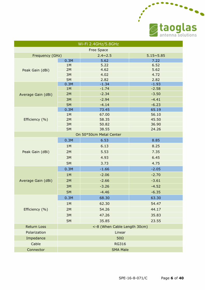
Wi-Fi 2.4GHz/5.8GHz
Free Space
Frequency (GHz) 2.4~2.5 5.15~5.85
Peak Gain (dBi)
0.3M 5.62 7.22
1M 5.22 6.52
2M 4.62 5.62
3M 4.02 4.72
5M 2.82 2.82
Average Gain (dBi)
0.3M -1.34 -1.93
1M -1.74 -2.58
2M -2.34 -3.50
3M -2.94 -4.41
5M -4.14 -6.23
Efficiency (%)
0.3M 73.45 65.19
1M 67.00 56.10
2M 58.35 45.50
3M 50.82 36.90
5M 38.55 24.26
On 50*50cm Metal Center
Peak Gain (dBi)
0.3M 6.53 8.85
1M 6.13 8.25
2M 5.53 7.35
3M 4.93 6.45
5M 3.73 4.75
Average Gain (dBi)
0.3M -1.66 -2.05
1M -2.06 -2.70
2M -2.66 -3.61
3M -3.26 -4.52
5M -4.46 -6.35
Efficiency (%)
0.3M 68.30 63.30
1M 62.30 54.47
2M 54.26 44.17
3M 47.26 35.83
5M 35.85 23.55
Return Loss <-8 (When Cable Length 30cm)
Polarization Linear
Impedance 50Ω
Cable RG316
Connector SMA Male
SPE-16-8-071/C Page 7 of 40
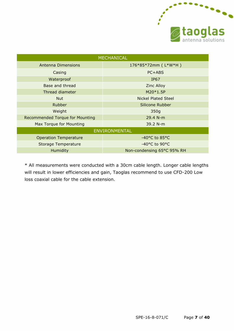
MECHANICAL
Antenna Dimensions 176*85*72mm ( L*W*H )
Casing PC+ABS
Waterproof IP67
Base and thread Zinc Alloy
Thread diameter M20*1.5P
Nut Nickel Plated Steel
Rubber Silicone Rubber
Weight 350g
Recommended Torque for Mounting 29.4 N-m
Max Torque for Mounting 39.2 N-m
ENVIRONMENTAL
Operation Temperature -40°C to 85°C
Storage Temperature -40°C to 90°C
Humidity Non-condensing 65°C 95% RH
* All measurements were conducted with a 30cm cable length. Longer cable lengths
will result in lower efficiencies and gain, Taoglas recommend to use CFD-200 Low
loss coaxial cable for the cable extension.
SPE-16-8-071/C Page 8 of 40
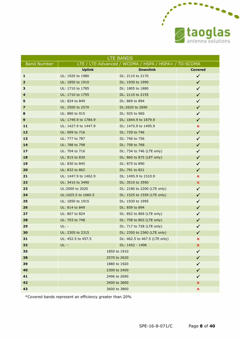
LTE BANDS
Band Number LTE / LTE-Advanced / WCDMA / HSPA / HSPA+ / TD-SCDMA
Uplink Downlink Covered
1 UL: 1920 to 1980 DL: 2110 to 2170 ✓ 2 UL: 1850 to 1910 DL: 1930 to 1990 ✓ 3 UL: 1710 to 1785 DL: 1805 to 1880 ✓ 4 UL: 1710 to 1755 DL: 2110 to 2155 ✓ 5 UL: 824 to 849 DL: 869 to 894 ✓ 7 UL: 2500 to 2570 DL:2620 to 2690 ✓ 8 UL: 880 to 915 DL: 925 to 960 ✓ 9 UL: 1749.9 to 1784.9 DL: 1844.9 to 1879.9 ✓ 11 UL: 1427.9 to 1447.9 DL: 1475.9 to 1495.9 12 UL: 699 to 716 DL: 729 to 746 ✓ 13 UL: 777 to 787 DL: 746 to 756 ✓ 14 UL: 788 to 798 DL: 758 to 768 ✓ 17 UL: 704 to 716 DL: 734 to 746 (LTE only) ✓ 18 UL: 815 to 830 DL: 860 to 875 (LET only) ✓ 19 UL: 830 to 845 DL: 875 to 890 ✓ 20 UL: 832 to 862 DL: 791 to 821 ✓ 21 UL: 1447.9 to 1462.9 DL: 1495.9 to 1510.9 22 UL: 3410 to 3490 DL: 3510 to 3590 23 UL:2000 to 2020 DL: 2180 to 2200 (LTE only) ✓ 24 UL:1625.5 to 1660.5 DL: 1525 to 1559 (LTE only) ✓ 25 UL: 1850 to 1915 DL: 1930 to 1995 ✓ 26 UL: 814 to 849 DL: 859 to 894 ✓ 27 UL: 807 to 824 DL: 852 to 869 (LTE only) ✓ 28 UL: 703 to 748 DL: 758 to 803 (LTE only) ✓ 29 UL: - DL: 717 to 728 (LTE only) ✓ 30 UL: 2305 to 2315 DL: 2350 to 2360 (LTE only) ✓ 31 UL: 452.5 to 457.5 DL: 462.5 to 467.5 (LTE only) 32 UL: - DL: 1452 - 1496 35 1850 to 1910 ✓ 38 2570 to 2620 ✓ 39 1880 to 1920 ✓ 40 2300 to 2400 ✓ 41 2496 to 2690 ✓ 42 3400 to 3600 43 3600 to 3800
*Covered bands represent an efficiency greater than 20%
SPE-16-8-071/C Page 9 of 40
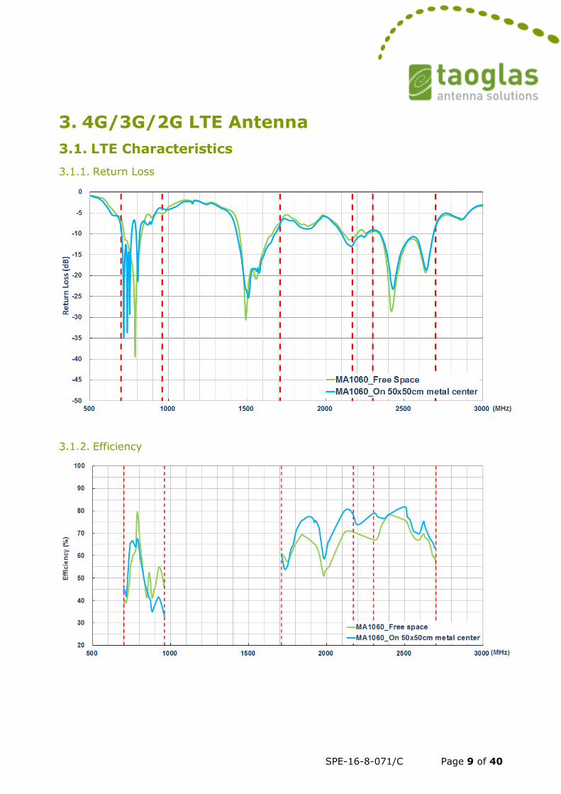
3. 4G/3G/2G LTE Antenna
3.1. LTE Characteristics
Return Loss
Efficiency
SPE-16-8-071/C Page 10 of 40
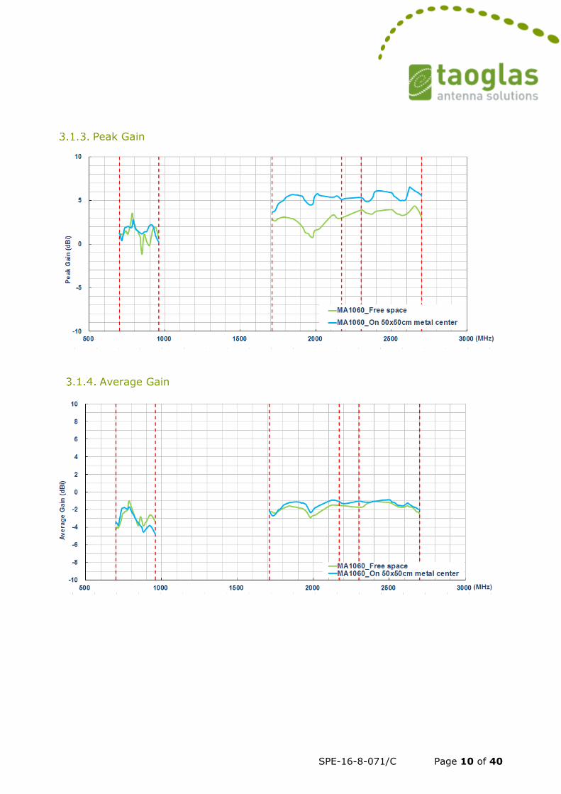
Peak Gain
Average Gain
SPE-16-8-071/C Page 11 of 40
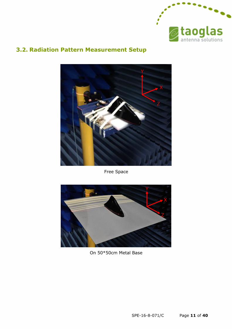
3.2. Radiation Pattern Measurement Setup
Free Space
On 50*50cm Metal Base
Y
X
Z
Y
X
Z
SPE-16-8-071/C Page 12 of 40
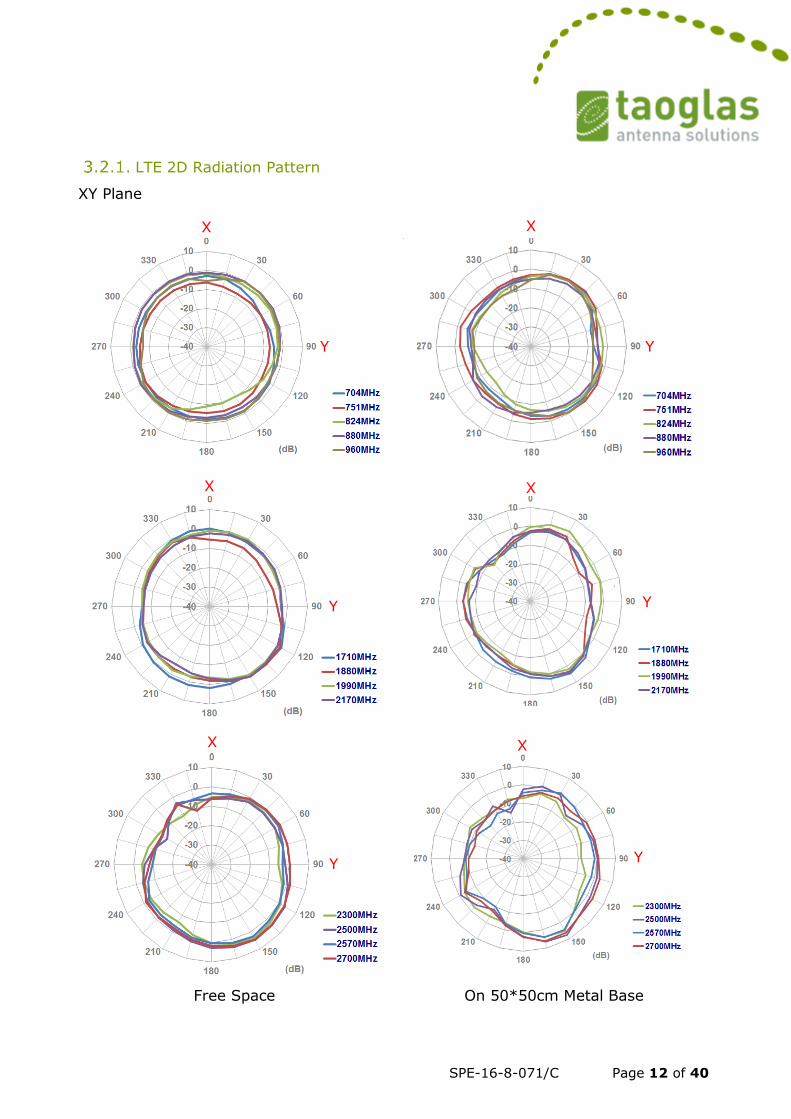
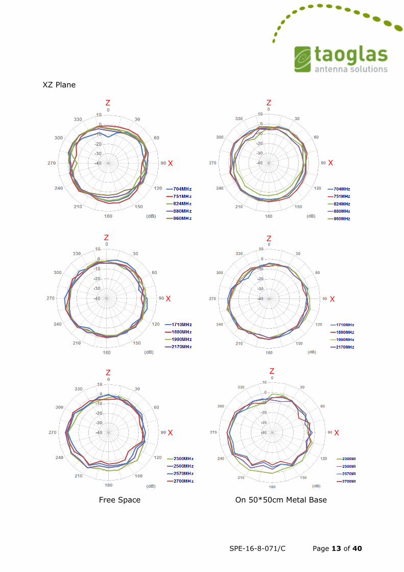
LTE 2D Radiation Pattern
XY Plane
Free Space On 50*50cm Metal Base
Y
X
Y
X
X
X X
Y Y
Y Y
X
SPE-16-8-071/C Page 13 of 40
XZ Plane
Free Space On 50*50cm Metal Base
Z
X
X X
Z Z
X X
Z
Z
X
Z
SPE-16-8-071/C Page 14 of 40
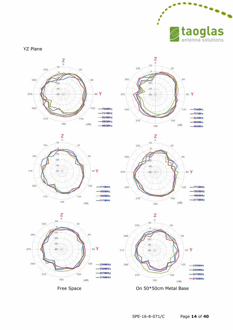
YZ Plane
Free Space On 50*50cm Metal Base
Y
Z
Y
Z
Y Y
Z Z
Y Y
Z Z
SPE-16-8-071/C Page 15 of 40
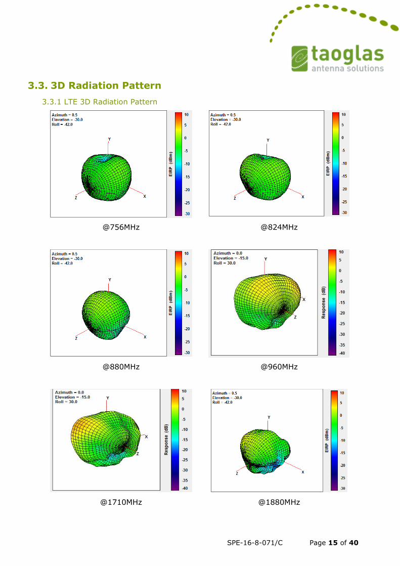
3.3. 3D Radiation Pattern
3.3.1 LTE 3D Radiation Pattern
@756MHz
@824MHz
@880MHz
@960MHz
@1710MHz @1880MHz
SPE-16-8-071/C Page 16 of 40
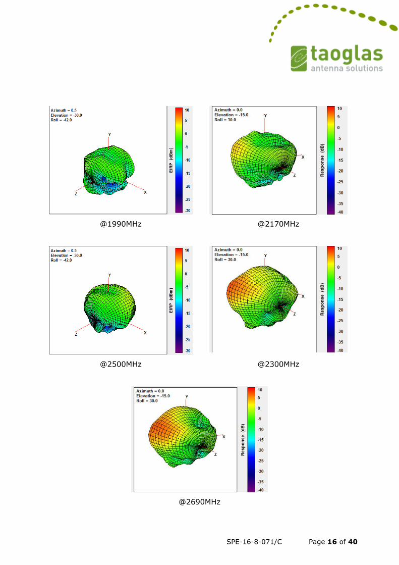
@1990MHz
@2170MHz
@2500MHz
@2300MHz
@2690MHz
SPE-16-8-071/C Page 17 of 40
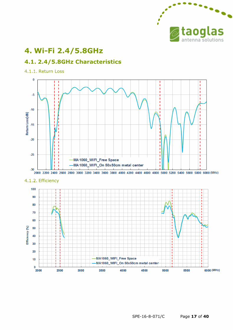
4. Wi-Fi 2.4/5.8GHz
4.1. 2.4/5.8GHz Characteristics
Return Loss
Efficiency
-30
-25
-20
-15
-10
-5
0
2100 2400 2700 3000 3300 3600 3900 4200 4500 4800 5100 5400 5700 6000
Retu
rn L
oss [d
B]
Frequency [MHz]
WiFi on 30x30cm ground plane
SPE-16-8-071/C Page 18 of 40
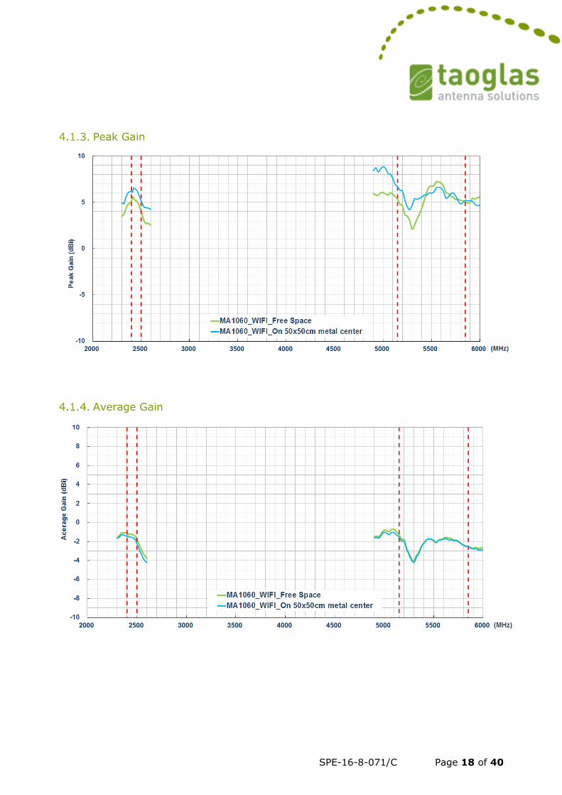
Peak Gain
Average Gain
SPE-16-8-071/C Page 19 of 40
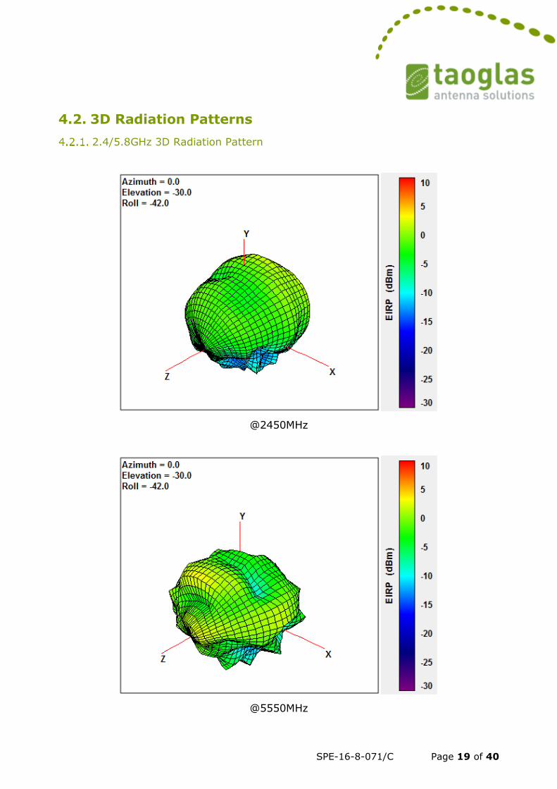
4.2. 3D Radiation Patterns
2.4/5.8GHz 3D Radiation Pattern
@2450MHz
@5550MHz
SPE-16-8-071/C Page 20 of 40
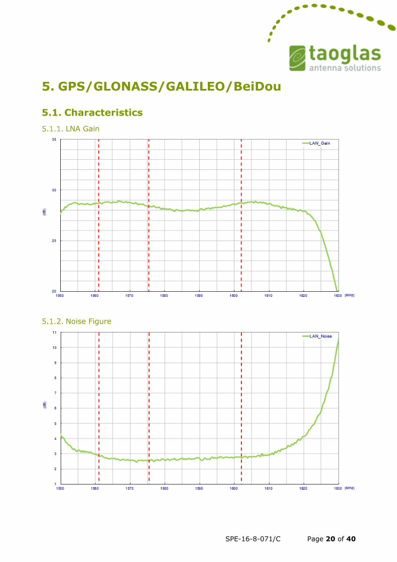
5. GPS/GLONASS/GALILEO/BeiDou
5.1. Characteristics
LNA Gain
Noise Figure
SPE-16-8-071/C Page 21 of 40
Patch Antenna Passive Return Loss
Patch Antenna Passive Efficiency
SPE-16-8-071/C Page 22 of 40
Patch Antenna Passive Peak Gain
SPE-16-8-071/C Page 23 of 40
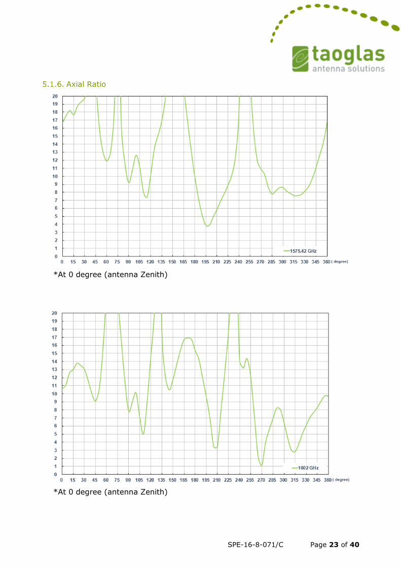
Axial Ratio
*At 0 degree (antenna Zenith)
*At 0 degree (antenna Zenith)
SPE-16-8-071/C Page 24 of 40
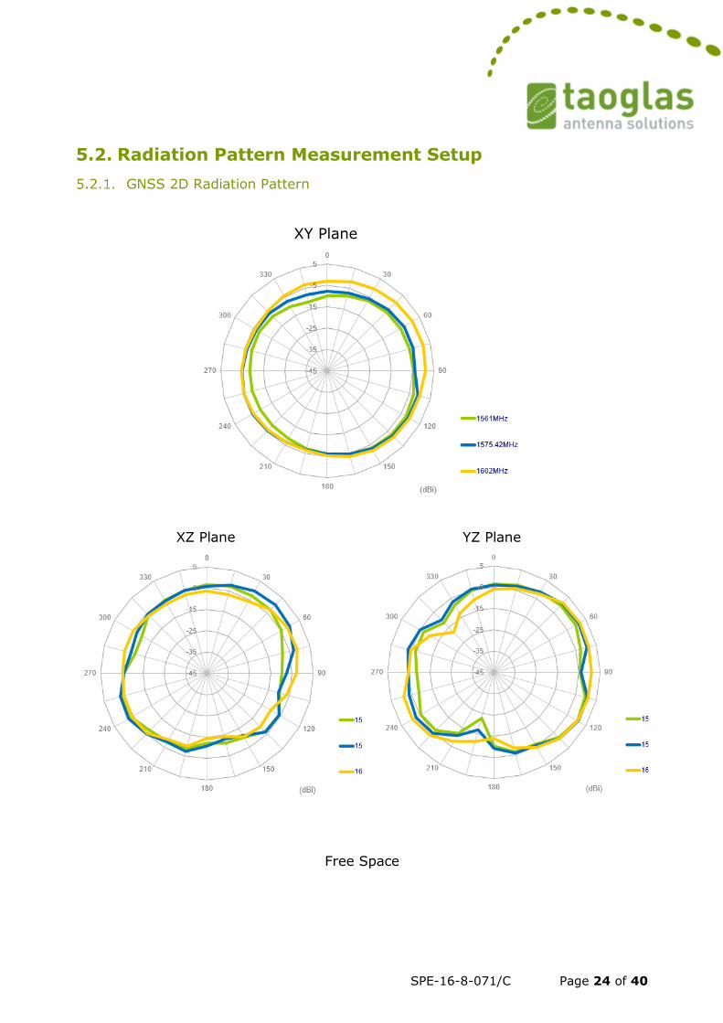
5.2. Radiation Pattern Measurement Setup
GNSS 2D Radiation Pattern
XY Plane
XZ Plane YZ Plane
Free Space
SPE-16-8-071/C Page 25 of 40
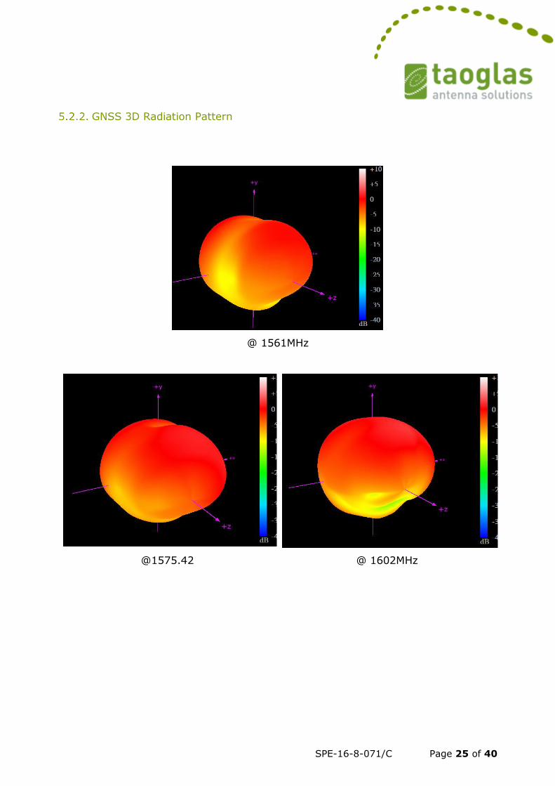
GNSS 3D Radiation Pattern
@ 1561MHz
@1575.42 @ 1602MHz
SPE-16-8-071/C Page 26 of 40
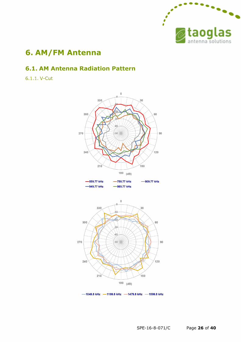
6. AM/FM Antenna
6.1. AM Antenna Radiation Pattern
V-Cut
SPE-16-8-071/C Page 27 of 40
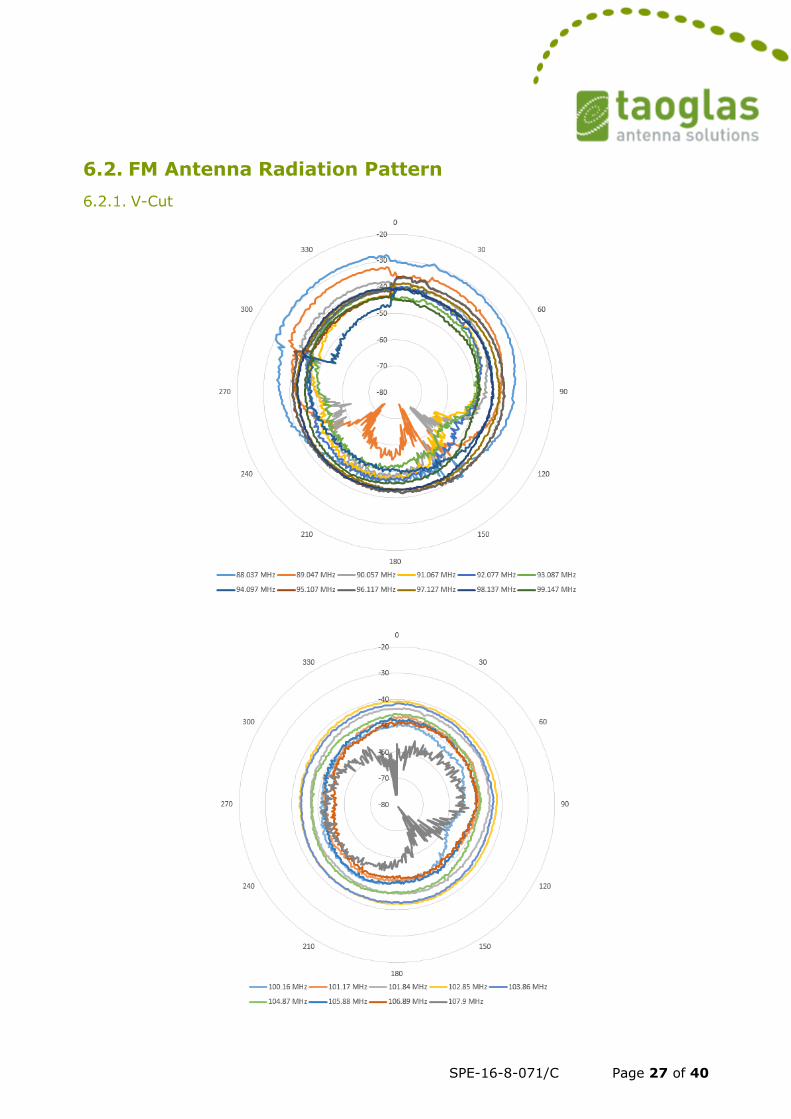
6.2. FM Antenna Radiation Pattern
V-Cut
SPE-16-8-071/C Page 28 of 40
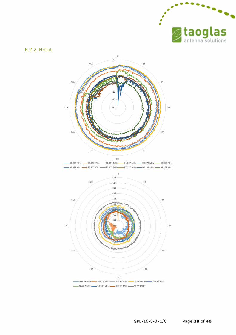
H-Cut
SPE-16-8-071/C Page 29 of 40
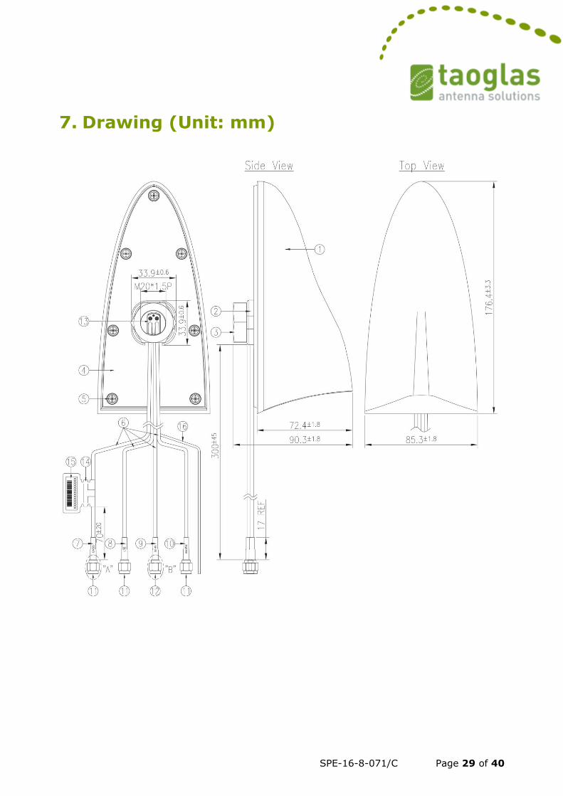
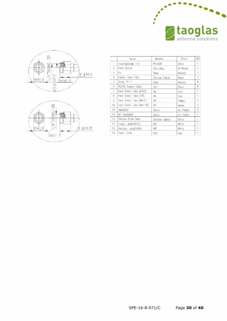
7. Drawing (Unit: mm)
SPE-16-8-071/C Page 30 of 40
SPE-16-8-071/C Page 31 of 40
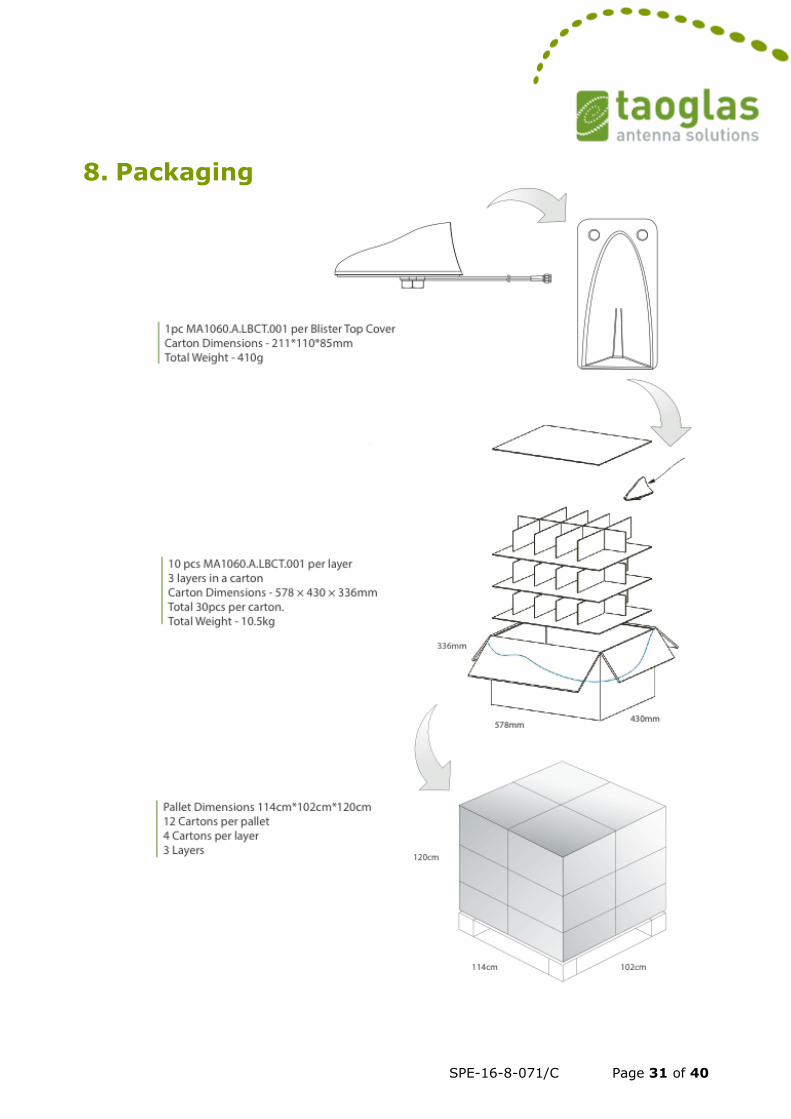
8. Packaging
SPE-16-8-071/C Page 32 of 40
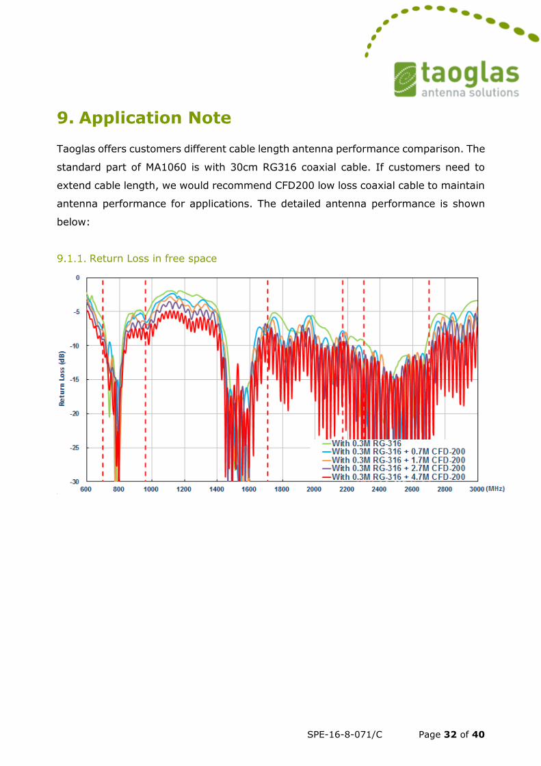
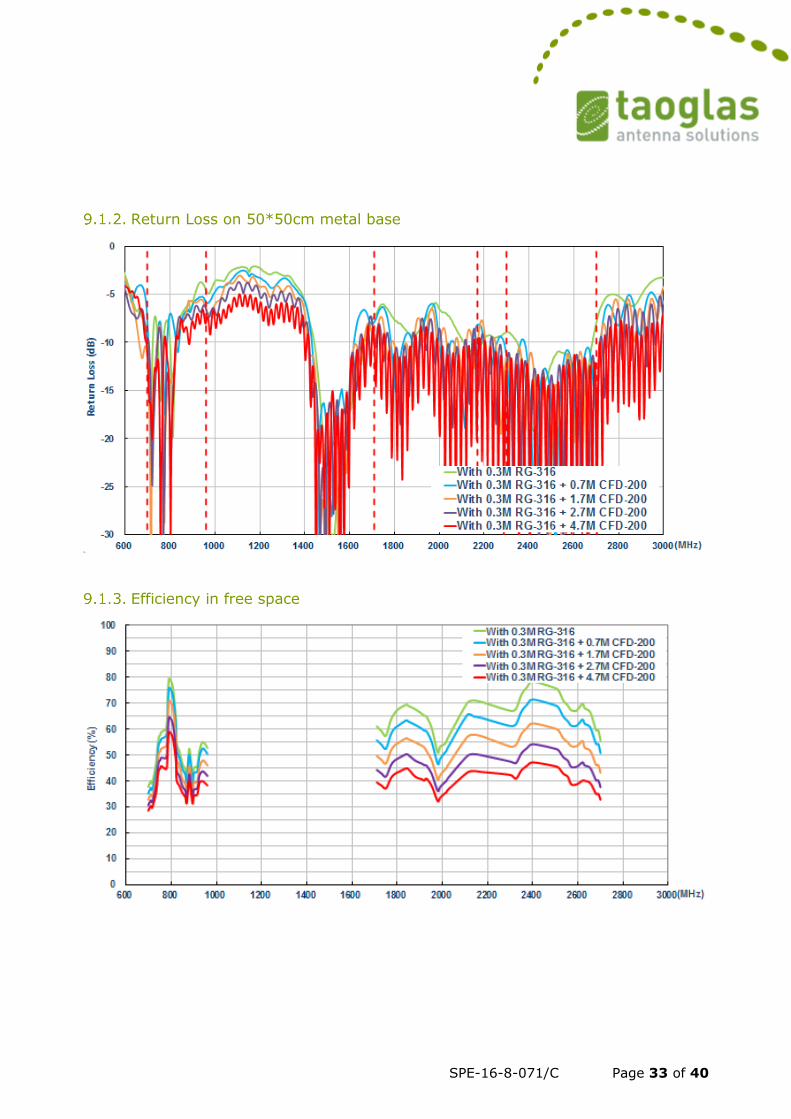
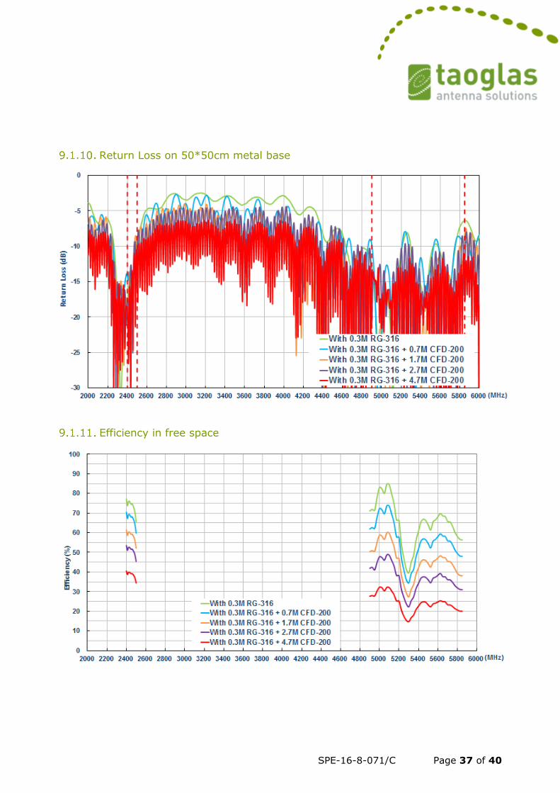
9. Application Note
Taoglas offers customers different cable length antenna performance comparison. The
standard part of MA1060 is with 30cm RG316 coaxial cable. If customers need to
extend cable length, we would recommend CFD200 low loss coaxial cable to maintain
antenna performance for applications. The detailed antenna performance is shown
below:
Return Loss in free space
SPE-16-8-071/C Page 33 of 40
Return Loss on 50*50cm metal base
Efficiency in free space
SPE-16-8-071/C Page 34 of 40
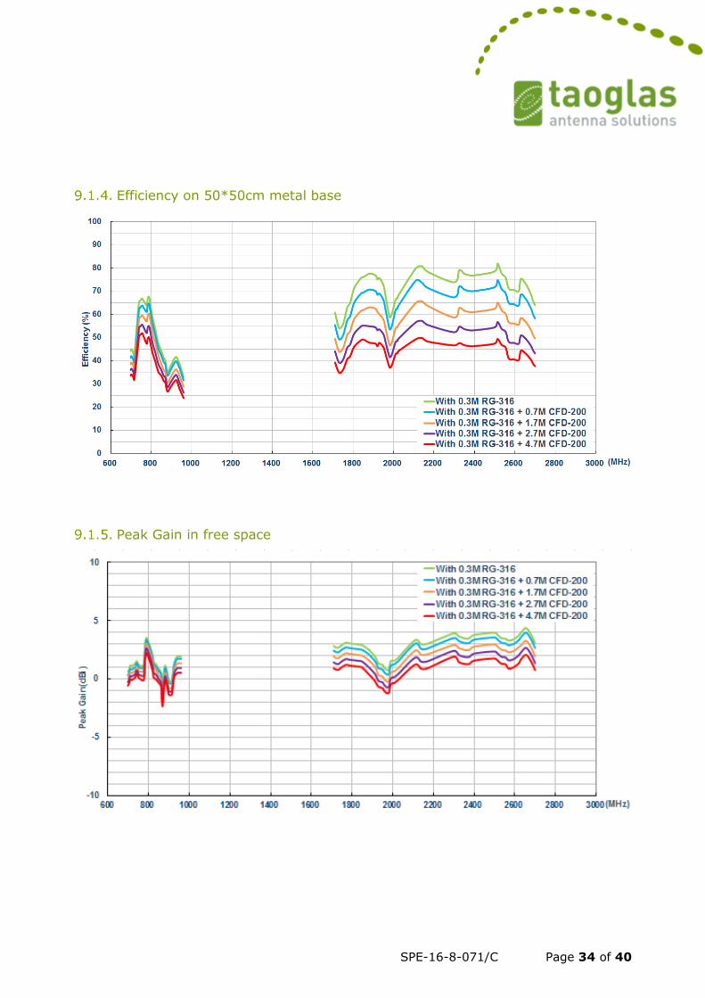
Efficiency on 50*50cm metal base
Peak Gain in free space
SPE-16-8-071/C Page 35 of 40
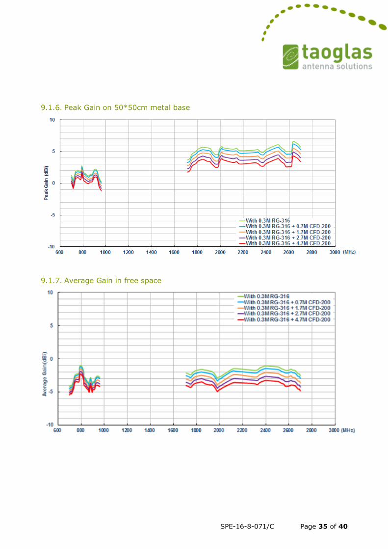
Peak Gain on 50*50cm metal base
Average Gain in free space
SPE-16-8-071/C Page 36 of 40
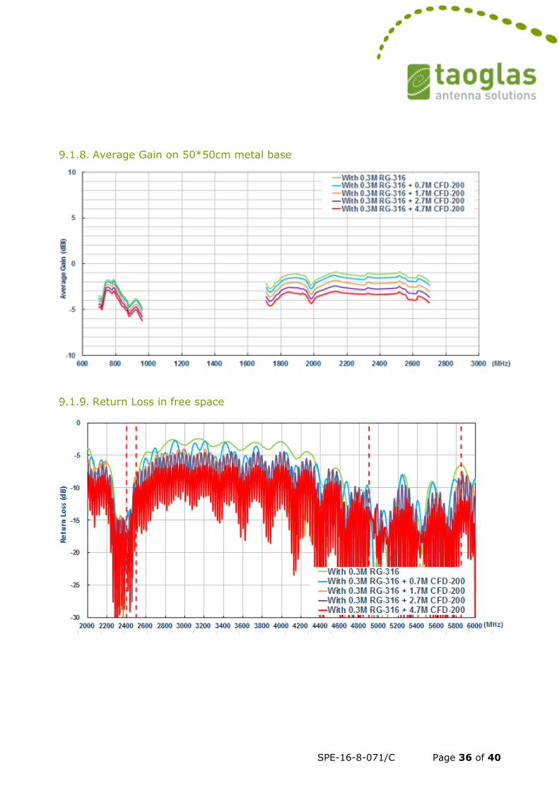
Average Gain on 50*50cm metal base
Return Loss in free space
SPE-16-8-071/C Page 37 of 40
Return Loss on 50*50cm metal base
Efficiency in free space
SPE-16-8-071/C Page 38 of 40
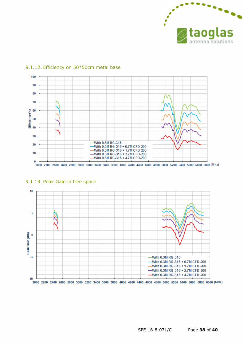
Efficiency on 50*50cm metal base
Peak Gain in free space
SPE-16-8-071/C Page 39 of 40
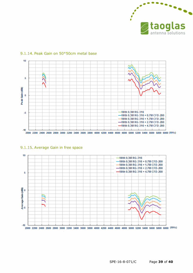
Peak Gain on 50*50cm metal base
Average Gain in free space
SPE-16-8-071/C Page 40 of 40
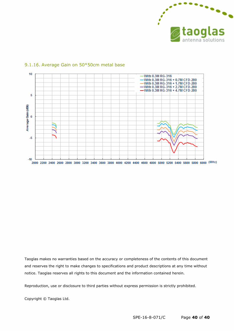
Average Gain on 50*50cm metal base
Taoglas makes no warranties based on the accuracy or completeness of the contents of this document
and reserves the right to make changes to specifications and product descriptions at any time without
notice. Taoglas reserves all rights to this document and the information contained herein.
Reproduction, use or disclosure to third parties without express permission is strictly prohibited. Copyright © Taoglas Ltd.