specification of the infrastructure virtualisation ...€¦ · t-nova | deliverable d2.31...
TRANSCRIPT

T-NOVA | Deliverable D2.31 Specification of the Infrastructure Virtualisation,
Management and Orchestration - Interim
© T-NOVA Consortium
1
Deliverable D2.31
Specification of the Infrastructure
Virtualisation, Management and
Orchestration - Interim
Editor Antonio Gamelas (PTIN)
Contributors Pedro Neves, Jose Bonnet, Antonio Gamelas (PTIN), Michael J.
McGrath, Vincenzo Riccobene (INTEL), Dora Christofi, Georgios
Dimosthenous (PTL), Beppe Coffano, Luca Galluppi, Pierangelo
Magli, Marco Di Girolamo (HP), Letterio Zuccaro, Federico
Cimorelli, Antonio Pietrabissa, Raffaele Gambuti (CRAT), George
Xilouris (NCSRD), Zdravko Bozakov, Panagiotis Papadimitriou
(LUH), Jordi Ferrer Riera (i2CAT)
Version 1.0
Date September 30th, 2014
Distribution RESTRICTED (RE)
T-NOVA | Deliverable D2.31 Specification of the Infrastructure Virtualisation,
Management and Orchestration - Interim
© T-NOVA Consortium
2
Executive Summary
The specification presented in this document utilises the requirements described in
previous deliverables together with the latest NFV and virtualisation requirements
defined by various industry bodies including the ETSI ISG NFV and ITU-T, as well as
excerpts of relevant parts of the ETSI ISG MANO WG architecture and associated
Functional Entities (FEs). Information assembled via this process was used as the
critical input into a two stage process. Stage 1 consisted of a research and design
phase, where a systems engineering approach was adopted to define the key
functional blocks and their associated capabilities. Stage 2 defined both the reference
architectures and its FEs, which are described in this document. Both the architecture
and associated FEs are presented in a technology agnostic manner to decouple the
specifics of the implementations details. An additional third stage which constitutes
the key activities within WP3/4 will address the specifics of the appropriate
technologies to be utilised and their operation.
Section 1 introduces the main technical areas addressed by this deliverable such as
virtualisation, the evolution of IT compute technologies in to the carrier domain, the
advent of software defined networking etc. In addition, it also presents the T-NOVA
solution constituted by both the T-NOVA Orchestration platform and the T-NOVA
Infrastructure Virtualisation Layer (IVM) platform. This section concludes by
presenting and describing its functional architecture.
Section 2, provides a concise review of the current state-of-the-art technologies and
industry/academic initiatives that are relevant to the Orchestration and Infrastructure
Virtualisation layers in T-NOVA. While there is strong focus on ETSI related activities,
a broad perspective has been adopted in this deliverable in order to ensure that all
relevant influences are suitably considered and filtered to make sure that the
architectural components considered in this document include the state-of-the-art
architectural and technology related approaches in their design and specification.
Section 3 provides the Orchestration layer specifications by starting with an overview
of its framework, the Orchestrator Domain, followed by the requirements of the
associated FEs, and concluding by presenting and describing its functional
architecture.
Section 4 presents the overall integrated architecture for the IVM layer together with
the architecture of the various domains that comprise the IVM with their respective
internal and external interfaces. Collectively, these reference architectures and FEs
instantiate the requirements that were identified for the T-NOVA Orchestrator and
IVM together with their goals and objectives.
Section 5 presents the key Virtualised Network Function (VNF) and Network Service
(NS) workflows that should be supported by the T-NOVA architecture. The reference
architectures were interrogated and validated at a functional level through the
development of these NS and VNF workflow diagrams, which illustrated the key
actions and interactions within the T-NOVA system during standard operational
activities related to the deployment and management of NS and VNF services.

T-NOVA | Deliverable D2.31 Specification of the Infrastructure Virtualisation,
Management and Orchestration - Interim
© T-NOVA Consortium
3
Section 6 provides the results of a focused gap analysis that was carried out to
determine what steps need to be taken in order to move NFV/SDN from its current
state to a position that can fully realise the needs of carrier grade deployments.
Annexes A and B contain the requirements for Orchestrator’s and IVM’s Functional
Entities, while Annex C contains a definition for several terms used throughout the
present deliverable. Finally, Appendix I constitute a repository of relevant information
on the ETSI ISG NFV framework.

T-NOVA | Deliverable D2.31 Specification of the Infrastructure Virtualisation,
Management and Orchestration - Interim
© T-NOVA Consortium
4
Table of Contents
1. INTRODUCTION ..................................................................................................... 11
1.1. VIRTUALISATION .............................................................................................................................. 11
1.1.1 The Virtualisation Concept ....................................................................................... 11
1.1.2 The Pros and Cons of NFV Deployments ............................................................. 13
1.2 THE T-NOVA SOLUTION ......................................................................................................... 14
1.2.1 The T-NOVA Orchestration Platform ................................................................... 15
1.2.2 The T-NOVA IVM Platform ....................................................................................... 16
2. SOTA SURVEY ......................................................................................................... 17
2.1. GLOBAL SPECIFICATIONS COMING FROM MAIN SDOS/FORA .................................................. 17
2.1.1 ETSI ISG NFV .................................................................................................................. 17 2.1.1.1. WG INF (Infrastructure Architecture) .................................................................................................... 17 2.1.1.2. WG SWA (Software Architecture) ........................................................................................................... 18 2.1.1.3. WG MANO (Management and Orchestration Architecture) ........................................................ 19
2.1.2 ITU-T ................................................................................................................................ 20 2.1.2.1 Virtualisation in ITU-T .......................................................................................................................... 20 2.1.2.2 Work carried out by ITU-T SG13 ..................................................................................................... 23
2.1.3 IETF ................................................................................................................................... 26 2.1.3.1 NETCONF ................................................................................................................................................. 26 2.1.3.2 YANG ......................................................................................................................................................... 26
2.1.4 TMF – ZOOM ................................................................................................................. 27
2.1.5 CloudNFV ....................................................................................................................... 28
2.2 VIM AND CONTROL SPECIFIC AREAS ...................................................................................... 30
2.2.1 IT Virtualisation Methods .......................................................................................... 30 2.2.1.1 Hypervisors .............................................................................................................................................. 31 2.2.1.2 Open Source and Commercial Hypervisors ................................................................................. 32 2.2.1.3 Containers ................................................................................................................................................ 35
2.2.2 Compute, Network I/O and Storage Virtualisation .......................................... 36 2.2.2.1 Microprocessor Virtualisation ........................................................................................................... 37 2.2.2.2 Intel Virtualisation Technology (Intel VT) ..................................................................................... 37 2.2.2.3 AMD's Virtualisation (AMD-V) Opteron ........................................................................................ 37 2.2.2.4 Storage Virtualisation .......................................................................................................................... 38 2.2.2.5 Software and Hardware -Assisted Network Virtualisation ..................................................... 39 2.2.2.6 Data Plane Development Kit (DPDK) ............................................................................................. 41
2.2.3 Cloud Environments and Controllers .................................................................... 43 2.2.3.1 OpenStack................................................................................................................................................ 43 2.2.3.2 Eucalyptus ................................................................................................................................................ 44 2.2.3.3 Cloudstack ............................................................................................................................................... 44 2.2.3.4 VMware vCloud Suite .......................................................................................................................... 45
2.2.4 Network Resource Virtualisation and Management ........................................ 45 2.2.4.1 Tunnelling Protocols ............................................................................................................................ 45 2.2.4.2 Software Defined Network Controllers ......................................................................................... 48 2.2.4.3 NaaS platforms ...................................................................................................................................... 51
3 THE T-NOVA ORCHESTRATION LAYER ............................................................ 56
3.1 ORCHESTRATION LAYER OVERVIEW ....................................................................................... 56
3.2 ORCHESTRATOR REQUIREMENTS ............................................................................................. 59
3.2.1 NFVO requirements types ......................................................................................... 60

T-NOVA | Deliverable D2.31 Specification of the Infrastructure Virtualisation,
Management and Orchestration - Interim
© T-NOVA Consortium
5
3.2.1.1 NS Lifecycle ............................................................................................................................................. 61 3.2.1.2 VNF Lifecycle ........................................................................................................................................... 61 3.2.1.3 Resource Handling ............................................................................................................................... 62 3.2.1.4 Monitoring Process .............................................................................................................................. 62 3.2.1.5 Connectivity Handling ......................................................................................................................... 63 3.2.1.6 Policy Management.............................................................................................................................. 63 3.2.1.7 Marketplace-specific interactions ................................................................................................... 64
3.2.2 VNFM requirements types......................................................................................... 64 3.2.2.1 VNF Lifecycle ........................................................................................................................................... 65 3.2.2.2 Monitoring Process .............................................................................................................................. 65
3.3 FUNCTIONAL ORCHESTRATOR ARCHITECTURE ...................................................................... 65
3.3.1 Reference Architecture ............................................................................................... 65
3.3.2 Functional entities ....................................................................................................... 66 3.3.2.1 Network Function Virtualisation Orchestrator (NFVO) ............................................................ 66 3.3.2.2 Virtual Network Function Manager (VNFM) ................................................................................ 70 3.3.2.3 Repositories and Catalogues ............................................................................................................ 72
3.3.3 External Interfaces ....................................................................................................... 73 3.3.3.1 Interface between the Orchestrator and the Network Function Store .............................. 74 3.3.3.2 Interface between the Orchestrator and the Marketplace ..................................................... 74 3.3.3.3 Interface between the Orchestrator and the VIM ..................................................................... 75 3.3.3.4 Interface between the Orchestrator and the Transport Network Management ............ 76 3.3.3.5 Interface between the Orchestrator and the VNF ..................................................................... 76
4. THE T-NOVA IVM LAYER .................................................................................... 78
4.1 INTRODUCTION .................................................................................................................... 78
4.2 OBJECTIVES AND CHARACTERISTICS OF THE T-NOVA IVM LAYER ................... 79
4.3 T-NOVA IVM LAYER REQUIREMENTS ........................................................................... 80
4.3.1 Virtual Infrastructure Manager ............................................................................... 81
4.3.2 Transport Network Management ........................................................................... 82
4.3.3 NFVI Compute .............................................................................................................. 82
4.3.4 NFVI Hypervisor ........................................................................................................... 82
4.3.5 NFVI DC Network ........................................................................................................ 82
4.4 T-NOVA IVM ARCHITECTURE ............................................................................................... 83
4.4.1 External Interfaces ....................................................................................................... 83
4.4.2 Internal IVM Interfaces ............................................................................................... 86
4.5 NFVI AND NFVI-POP .............................................................................................................. 88
4.5.1 IT Resources ................................................................................................................... 89 4.5.1.1 Compute Domain .................................................................................................................................. 89 4.5.1.2 Hypervisor Domain ............................................................................................................................... 94
4.5.2 Infrastructure Network Domain .............................................................................. 95
4.6 VIRTUALISED INFRASTRUCTURE MANAGEMENT .................................................................... 97
4.6.1 IT Resource Management and Control ................................................................. 99 4.6.1.1 Hypervisor Management .................................................................................................................... 99 4.6.1.2 Computing Resources Management ............................................................................................. 99
4.6.2 Infrastructure Network Resources Management and Monitoring ............ 101
4.7 TRANSPORT NETWORK MANAGEMENT .............................................................................. 102
4.7.1 Network Resources Management and Monitoring ........................................ 103 4.7.1.1 SDN-enabled Network Elements .................................................................................................. 103 4.7.1.2 Legacy Network Elements ............................................................................................................... 104
5 T-NOVA VNFS AND NSS PROCEDURES ......................................................... 106
T-NOVA | Deliverable D2.31 Specification of the Infrastructure Virtualisation,
Management and Orchestration - Interim
© T-NOVA Consortium
6
5.1 VNF RELATED PROCEDURES .................................................................................................. 106
5.1.1 On-boarding ............................................................................................................... 106
5.1.2 Instantiation................................................................................................................ 107
5.1.3 Supervision .................................................................................................................. 111
5.1.4 Scale-out ...................................................................................................................... 114
5.1.5 Termination ................................................................................................................ 116
5.2 NS RELATED PROCEDURES .................................................................................................... 119
5.2.1 On-boarding ............................................................................................................... 119
5.2.2 Instantiation................................................................................................................ 120
5.2.3 Supervision .................................................................................................................. 123
5.2.4 Scale-out ...................................................................................................................... 124
5.2.5 Termination ................................................................................................................ 127
5.3 NS, VNF AND INFRASTRUCTURE MONITORING ................................................................ 127
6 GAP ANALYSIS ................................................................................................. 131
6.1 COMPUTE ................................................................................................................................ 131
6.2 HYPERVISOR ............................................................................................................................ 132
6.3 SDN CONTROLLERS .............................................................................................................. 132
6.4 CLOUD CONTROLLERS ........................................................................................................... 133
6.5 NETWORK VIRTUALISATION .................................................................................................. 134
6.6 NFV ORCHESTRATOR ............................................................................................................ 136
7 CONCLUSIONS ................................................................................................. 137
ANNEX A - ORCHESTRATOR REQUIREMENTS ..................................................... 140
A.1 INTERNAL REQUIREMENTS ..................................................................................................... 141
A.1.1 NFVO Requirements ................................................................................................ 141 A.1.1.1 NS Lifecycle requirements .............................................................................................................. 141 A.1.1.2 VNF Lifecycle requirements ............................................................................................................ 142 A.1.1.3 Resource Handling Requirements ............................................................................................... 143 A.1.1.4 Monitoring Process requirements ............................................................................................... 144 A.1.1.5 Connectivity Handling requirements .......................................................................................... 144 A.1.1.6 Policy Management requirements ............................................................................................... 145 A.1.1.7 Marketplace-specific interactions requirements .................................................................... 146
A.1.2 VNFM Requirements ................................................................................................ 147 A.1.2.1 VNF Lifecycle requirements ............................................................................................................ 147 A.1.2.2 Monitoring Process requirements ............................................................................................... 148
A.2 INTERFACE REQUIREMENTS ................................................................................................... 149
A.2.1 Interface with VIM .................................................................................................... 149
A.2.2 Interface with VNF .................................................................................................... 151
A.2.3 Interface with Marketplace .................................................................................... 152
ANNEX B - VIRTUALISED INFRASTRUCTURE MANAGEMENT REQUIREMENTS 154
B.1 VIRTUAL INFRASTRUCTURE MANAGEMENT REQUIREMENTS ............................................ 154
B.2 TRANSPORT NETWORK MANAGEMENT REQUIREMENTS .................................................. 158
B.3 NFV INFRASTRUCTURE REQUIREMENTS .............................................................................. 159
B.3.1 Computing .................................................................................................................. 159
B.3.2 Hypervisor ................................................................................................................... 162
B.3.3 Networking ................................................................................................................. 163

T-NOVA | Deliverable D2.31 Specification of the Infrastructure Virtualisation,
Management and Orchestration - Interim
© T-NOVA Consortium
7
ANNEX C - TERMINOLOGY ..................................................................................... 167
C.1 GENERAL TERMS ..................................................................................................................... 167
C.2 ORCHESTRATION DOMAIN ................................................................................................... 167
C.3 IVM DOMAIN ......................................................................................................................... 168
APPENDIX I – ETSI ISG NFV FRAMEWORK ........................................................... 170
I.1 ETSI ISG NFV OVERVIEW .................................................................................................... 170
I.2 HIGH-LEVEL NFV FRAMEWORK AND REFERENCE ARCHITECTURE .................................... 170
I.3 RELEVANT WORKING GROUPS AND EXPERT GROUPS ...................................................... 172
I.3.1 WG INF (Infrastructure Architecture) ...................................................................... 172
I.3.2 WG SWA (Software Architecture) ............................................................................. 173
I.3.3 WG MANO (Management and Orchestration Architecture) .......................... 174
I.4 ETSI ISG NFV IMPACT IN WP2 OF T-NOVA ................................................................... 175
I.5 STATUS OF WORK ................................................................................................................... 176
I.5.1 What has been achieved to date .............................................................................. 176
I.5.2 WG focus .......................................................................................................................... 177
I.5.3 Publication of documents for ETSI ISG NFV Release 1 ..................................... 178
I.5.4 Phase 2 preparation ..................................................................................................... 179 I.5.4.1 Global objectives ................................................................................................................................ 179 I.5.4.2 Governance model ............................................................................................................................ 179 I.5.4.3 Documents maintenance ................................................................................................................ 180 I.5.4.4 Issues related to NFV evolution .................................................................................................... 180 I.5.4.5 3
rd White Paper ................................................................................................................................... 180
I.5.4.6 Open Platform NFV ........................................................................................................................... 181
REFERENCES ............................................................................................................. 183
LIST OF ACRONYMS ................................................................................................ 188
T-NOVA | Deliverable D2.31 Specification of the Infrastructure Virtualisation,
Management and Orchestration - Interim
© T-NOVA Consortium
8
Index of Figures
Figure 1: High-level view of overall T-NOVA System Architecture ...................................... 15
Figure 2 High Level Overview of the NFVI Domains and Interfaces ................................... 18
Figure 3: SWA Architectural Framework and interfaces types ............................................... 19
Figure 4: NFV MANO reference architectural framework ....................................................... 20
Figure 5: Conceptual architecture of network virtualization .................................................. 21
Figure 6: Y.3001: Four objectives and twelve design goals of future networks .............. 24
Figure 7: ITU-T Future networks activity timeline (Roadmap) ............................................... 26
Figure 8: The CloudNFV Architecture (29)..................................................................................... 29
Figure 9: Relation between virtualisation technologies and T-NOVA architecture ....... 30
Figure 10: Hypervisor versus container based virtualisation approaches ......................... 35
Figure 11: VEB vs. VEPA ........................................................................................................................ 39
Figure 12: SR-IOV PF and VF conceptual overview .................................................................... 41
Figure 13: Cloud Management System Deployments .............................................................. 43
Figure 14: Open Networking Foundation Software-Defined Network Architecture ..... 49
Figure 15: OpenNaaS Architecture (left), NaaS Resource Abstraction (right) ................. 52
Figure 16: NSs & VNFs Complex Orchestration Overview ...................................................... 58
Figure 17: T-NOVA Orchestrator Reference Architecture ....................................................... 66
Figure 18: NS Orchestrator (Internal & External) Interactions ............................................... 68
Figure 19: Virtualised Resources Orchestrator (Internal & External) Interactions .......... 70
Figure 20: VNF Manager (Internal & External) Interactions .................................................... 71
Figure 21: T-NOVA infrastructure virtualisation and management (IVM) high level
architecture ............................................................................................................................................... 84
Figure 22: Compute Domain High Level Architecture .............................................................. 93
Figure 23: Hypervisor domain architecture .................................................................................. 95
Figure 24: High level architecture of the Infrastructure Network ......................................... 96
Figure 25: T-NOVA VIM high level architecture .......................................................................... 98
Figure 26: VIM Network Control Architecture .......................................................................... 101
Figure 27: VNF On-boarding Procedure ..................................................................................... 107
Figure 28: VNF Instantiation Procedure (Orchestrator’s View) ........................................... 108
Figure 29: VNF Instantiation Procedure (IVM’s View) ............................................................ 110
Figure 30: VNF Supervision Procedure (Orchestrator’s View) ............................................. 112
Figure 31: VNF Supervision Procedure (IVM’s View) .............................................................. 113
Figure 32: Scaling out a VNF ........................................................................................................... 114
Figure 33: VNF Scale-out Procedure ............................................................................................ 115
Figure 34: VNF Termination Procedure – Orchestrator’s View ........................................... 117
Figure 35: VNF Termination Procedure – IVM’s View ............................................................ 118
Figure 36: NS On-boarding Procedure ........................................................................................ 119
Figure 37: NS Instantiation Procedure (Orchestrator’s View) ............................................. 120
Figure 38: NS Instantiation Procedure (IVM’ View) ................................................................. 122
Figure 39: NS Supervision Procedure ........................................................................................... 123
Figure 40: Scaling-out a NS ............................................................................................................. 125
Figure 41: NS Scale-out ..................................................................................................................... 126
Figure 42: NS Termination Procedure .......................................................................................... 127
Figure 43: Communication of monitoring information across the T-NOVA system .. 128

T-NOVA | Deliverable D2.31 Specification of the Infrastructure Virtualisation,
Management and Orchestration - Interim
© T-NOVA Consortium
9
Figure 44: High-level NFV framework .......................................................................................... 171
Figure 45: NFV reference architectural framework ................................................................. 171
Figure 46: High Level Overview of the NFVI Domains and Interfaces ............................. 173
Figure 47: SWA Architectural Framework and interfaces types ......................................... 174
Figure 48: NFV MANO reference architectural framework .................................................. 175
Figure 49: T-NOVA mapping into ETSI MANO ......................................................................... 176
Figure 50: Timeline for ISG Work Program from beginning of 2013 to mid-2014 ..... 177
Figure 51: Timeline for ISG Work Program during 2014 and beginning of 2015 ....... 178
T-NOVA | Deliverable D2.31 Specification of the Infrastructure Virtualisation,
Management and Orchestration - Interim
© T-NOVA Consortium
10
Index of Tables
Table 1: Comparison of Hypervisor Types .................................................................................... 32
Table 2: Comparison of key open source and commercial hypervisor technologies ... 34
Table 3: Comparison of Hypervisors and Container Approaches ........................................ 35
Table 4: Common VLAN Tunnelling Protocols ............................................................................ 47
Table 5: Key features of common SDN controllers .................................................................... 49
Table 6: External Interfaces of the T-NOVA IVM ........................................................................ 85
Table 7: Internal interfaces of the IVM ........................................................................................... 87
Table 8: Monitoring metrics per infrastructure domain ........................................................ 129
Table 9: Gap analysis in the compute domain ......................................................................... 131
Table 10: Gap analysis in the Hypervisor domain ................................................................... 132
Table 11: Gap analysis regarding SDN Controllers ................................................................. 132
Table 12: Gap analysis regarding Cloud Controllers .............................................................. 133
Table 13: Gap analysis regarding Network Virtualisation .................................................... 134
Table 14: Gap analysis regarding Orchestration ...................................................................... 136
Table 15: Orchestrator Requirements – NFVO- NS Lifecycle .............................................. 141
Table 16: Orchestrator Requirements – NFVO- VNF Lifecycle ........................................... 142
Table 17: Orchestrator Requirements – NFVO- Resource Handling ................................ 143
Table 18: Orchestrator Requirements – NFVO- Monitoring Process ............................... 144
Table 19: Orchestrator Requirements – NFVO- Connectivity Handling .......................... 144
Table 20: Orchestrator Requirements – NFVO- Policy Management .............................. 145
Table 21: Orchestrator Requirements – NFVO- Marketplace specific ............................. 146
Table 22: Orchestrator Requirements – VNFM- VNF Lifecycle ........................................... 147
Table 23: Orchestrator requirements – VNFM- Monitoring Process ............................... 148
Table 24: Requirements between the Orchestrator and VIM ............................................. 149
Table 25: Requirements between the Orchestrator and VNF ............................................. 151
Table 26: Requirements between the Orchestrator and the Marketplace ..................... 152
Table 27: IVM Requirements - VIM ............................................................................................... 154
Table 28: IVM Requirements - TNM ............................................................................................. 158
Table 29: IVM requirements - Computing ................................................................................. 159
Table 30: IVM Requirements - Hypervisor ................................................................................. 162
Table 31: IVM Requirements - Networking ............................................................................... 163
Table 32: General terms .................................................................................................................... 167
Table 33: Orchestration Domain terminology .......................................................................... 167
Table 34: IVM Domain terminology ............................................................................................. 168
Table 35: Overall GS documents status (as of June 18th) ...................................................... 177
Table 36: Expected timeline and outputs for the ETSI ISG NFV ......................................... 178

T-NOVA | Deliverable D2.31 Specification of the Infrastructure Virtualisation,
Management and Orchestration - Interim
© T-NOVA Consortium
11
1. INTRODUCTION
This deliverable outlines the outputs and the results of the activities carried out in
Tasks 2.3 and 2.4 in Work Package 2 (WP2). These outputs and results are focused on
the infrastructure virtualisation layer as well as of the management and orchestration
layer within the T-NOVA system.
1.1. Virtualisation
Virtualisation is a general term that can apply to a variety of different technology
approaches such as hardware, operating system, storage, memory and network. It is
the key enabler technology that allows traditional physical network functions to be
decoupled from fixed appliances and to be deployed onto industry standard servers
large Data Centres (DCs). This approach is providing operators with key benefits such
as greater flexibility, faster delivery of new services, a broader ecosystem enhancing
innovation in the network etc.
1.1.1 The Virtualisation Concept
From a computing perspective virtualisation abstracts the computing platform and, in
doing so, hides its physical characteristics from users or applications. Dating back to
the 1960’s, the concept of virtualisation was first introduced with the Atlas Computer
with the concept of virtual memory, and paging techniques for system memory. IBM’s
M44/44X project building on these innovations developed an architecture which first
introduced the concept of virtual machines (VMs). Their approach was based on a
combination of hardware and software allowing the logical slicing of one physical
server into multiple isolated virtual environments (1). Virtualisation has now evolved
from its initial mainframe origins to now being supported by the X86 architecture and
being adopted by other non-computing domain such as storage and networking.
The term Full Virtualisation describes the technique where a complete simulation of
the underlying hardware is provided. This approach has its origins in IBM’s control
programs for the CP/CMS operating system. Today this approach is used to emulate
a complete hardware environment in the form of a VM, in which a guest Operating
System (OS) runs in isolation. Full virtualisation wasn’t completely possible with the
x86 architecture until the addition of Intel’s VT and AMD-V extensions in 2005-2006.
In fact, full x86 virtualisation relies on binary translation to trap and virtualise the
execution of certain sensitivity “non-virtualisable” instructions. With this approach,
critical instructions are discovered and replaced with traps into the Virtual Machine
Manager (VMM), also called a hypervisor, to be emulated in software.
Virtualisation is now found in applications for other domains such as storage, and
network to deliver similar benefits to those realised in the compute domain.
Storage virtualisation refers to a process by which several physical disks
appear to be a single unit. Virtualised storage is typically block-level rather
than file-level, meaning that it looks like a normal physical drive to computers.

T-NOVA | Deliverable D2.31 Specification of the Infrastructure Virtualisation,
Management and Orchestration - Interim
© T-NOVA Consortium
12
The key advantages of the approach are: (i) easier management of
heterogeneous storage environments, (ii) better utilisation of resources, (iii)
greater flexibility in the allocation of storage to VMs,
Network virtualisation comes in many forms like Virtual Local Area Networks
(VLANs), Logical Storage Area Networks (LSANs) and Virtual Storage Area
Networks (VSANs) that allow a single physical Local Area Networks (LAN) or
Storage Area Networks (SAN) architecture to be carved up into separate
networks without dependence on the physical connection. Virtual Routing
and Forwarding (VRF) allows separate routing tables to be used on a single
piece of hardware to support different routes for different purposes. The
benefits of network virtualisation are very similar to server virtualisation,
namely increased utilisation and flexibility.
These technologies in the form of cloud computing are now being rapidly adopted
by network operators in their carrier network domains in order to consolidate
traditional network devices onto standard high volume x86 servers, switches and
storage in the form of VNFs. In doing so, they allow service providers to transform
their network functions into an elastic pool of resources while seeking compatibility
with network and operational management tools. Building on cloud DCs allows
operators to create an orchestration environment for the management and control of
their compute, network and storage resources. For VNFs to function properly the
configuration of the network underneath them is critical. To provision or adapt VNFs
to changing network conditions or customer requests requires the ability to configure
or adapt network routes in a highly expeditious manner.
The advent of Software Defined Networking (SDN) with its support for programmatic
provisioning transforms service delivery from weeks to a matter of minutes or even
seconds. SDN is based around a new networking model where control of the network
is decoupled from the physical hardware allowing a logically centralised software
program (a network controller) to control the behaviour of an entire network. The use
of centralised network control and a common communication layer protocol across
the switching elements in the network can enable increased network efficiency,
centralised traffic engineering, improve troubleshooting capabilities and the ability to
build multiple virtual networks running over a common physical network fabric. In
SDN, network elements are primarily focused on packet forwarding, whereas
switching and routing functions are managed by centralised network controller which
dynamically configures network elements using protocols such as OpenFlow. SDN is
starting to be deployed in data centre and enterprise environments e.g. Google.
Virtual networks to support VNF deployment can be deleted, modified or restored in
a matter of seconds in much the same manner that we provision virtual machines in
cloud environments.
Virtualisation and its adoption in the key constituent elements of networks and data
centres has created an agility for service providers that was not previously possible.
Virtualisation of infrastructure, networks as well as the applications and services that
run on top will allow service providers to rapidly transform their networks and to
embrace new innovations.

T-NOVA | Deliverable D2.31 Specification of the Infrastructure Virtualisation,
Management and Orchestration - Interim
© T-NOVA Consortium
13
1.1.2 The Pros and Cons of NFV Deployments
As highlighted by the ETSI ISG NFV in its first white paper (2), the scenario which
defines the situation faced by most network operators nowadays, relates to the
physical components of their networks, which are characterised by the use of a wide
range of proprietary hardware appliances. This problem of appliance and technology
diversity continues to grow for operators as new equipment is added to previous
generations of equipment in the network.
This leads to significant challenges related to the launch of new services, increasing
energy costs and capital investments coupled with the difficulty of finding people
with the most appropriate skills to handle the design, integration and operation of
increasingly complex hardware-based appliances. In addition, the trend towards
shorter operational lifespan of hardware also affects revenues, leading to situations
where there is no return on investment or where there is no time for innovation.
As previously outlined in the T-NOVA project scope (3), Network Functions
Virtualisation (NFV) will address these challenges by leveraging standard Information
Technology (IT) virtualisation technology to consolidate various network equipment
types onto industry standard high volume servers, switches and storage located in
DCs, Network Nodes and in the end user premises. In this context, NFV refers to the
virtualisation of network functions carried out by specialised hardware devices and
their migration to software-based appliances, which are deployed on top of
commodity IT (including Cloud) infrastructures.
Virtualising Network Functions potentially offers many benefits, including:
Reduction in both equipment costs and power consumption,
Reduced time to market,
Availability of network appliances that support multiple-versions and multi-
tenancy, with the ability to share resources across services,
Targeted service introduction based on geography or customer type, where
services can be quickly scaled up/down as required,
Enabling a wide variety of eco-systems,
Encouraging openness within the ecosystem.
One of the challenges in the deployment of NFV in the carrier domain is to leverage
the advantages of the IT ecosystem while minimising any of the associated
disadvantages. Standard high volume servers and software must be modified to meet
the specific reliability requirements in the telecoms environment, including 99.999
percent uptime availability. This mission critical level of reliability is a key requirement
and differentiates traditional IT (just reboot the system!) and telecom (where
downtime or poor performance is not acceptable) environments. To meet design
goals without sacrificing performance, software applications must be specifically
designed or rewritten to run optimally in virtualised telecom environments to meet
carrier grade requirements. Otherwise, applications ported to virtualised
environments may experience significant performance issues and may not scale
appropriately to the required network load. An additional challenge for virtualisation
in a telecom network environment is the requirement to deliver low latency to handle
real-time applications such as voice and video traffic. In addition to performance,

T-NOVA | Deliverable D2.31 Specification of the Infrastructure Virtualisation,
Management and Orchestration - Interim
© T-NOVA Consortium
14
other operational characteristics that are crucial to successful deployments include:
maturity of the hypervisor; Reliability, Availability, and Serviceability (RAS); scalability,
security, management and automation; support and maintainability.
Deploying NFV also incurs other well-defined risks, e.g. scalability in order to handle
carrier network demands; management of both IT and network resources in support
of network connectivity services and Network Functions (NFs) deployment; handling
of network fault and management operations; Operations Supporting System (OSS) /
Business Supporting System (BSS) backwards compatibility in migration situations;
interoperability required to achieve end-to-end services offerings, including end-to-
end Quality of Service (QoS). In addition, essential software appliances should achieve
performance comparable to their hardware counterparts which is currently not always
possible due a variety of reasons such as the performance of the virtualisation
technologies.
1.2 The T-NOVA Solution
The T-NOVA project is focused on addressing some of the key challenges of
deploying NFVs in carrier grade environments by designing and implementing an
integrated architecture, which includes a novel integrated open-source Orchestration
platform. This platform is explicitly dedicated to the orchestration of cloud and
network resources for NFVs, as well as the automated provisioning, management,
monitoring and optimisation of Network Functions-as-a-Service (NFaaS) over
virtualised Network/IT infrastructures. The T-NOVA Orchestrator controls the
infrastructure resources that host the VNFs via the T-NOVA IVM. The IVM is
comprised of a number of functionalities, which collectively provide the virtualised
compute, storage and network connectivity required to host VNFs.
The overall T-NOVA system architecture is depicted in the next figure and is on the
basis of the T-NOVA solution, which includes two platforms specified in the present
deliverable: the T-NOVA Orchestration platform and the T-NOVA IVM platform.

T-NOVA | Deliverable D2.31 Specification of the Infrastructure Virtualisation,
Management and Orchestration - Interim
© T-NOVA Consortium
15
Figure 1: High-level view of overall T-NOVA System Architecture
(Source: D2.21 (4))
1.2.1 The T-NOVA Orchestration Platform
The T-NOVA architecture has been conceived using a layer stratification approach
where the Orchestration layer is positioned between the Service Layer and the
Infrastructure Management layers. This stratification approach, together with the
envisaged high level modules within the Orchestrator layer, is illustrated in Figure 1
above.
The capabilities of the T-NOVA Orchestrator are required to extend beyond
traditional cloud management as the T-NOVA scope is not restricted to a single DC.
The Orchestrator therefore needs to manage and monitor Wide-Area Networks
(WANs) as well as distributed cloud (compute/storage) services and resources in
order to couple basic network connectivity services with added-value NFs.
Orchestration layer capabilities that could improve the deployment of VNFs onto
private, heterogeneous cloud, includes:
Application assignment to hardware platforms capable of improving its
performance though specific features, such as special purpose instructions or
accelerators,
Allocation of an Single Root I/O Virtualisation (SR-IOV) virtual function to VMs
running VNFs that can benefit from the capability,
Enabling live-migration.

T-NOVA | Deliverable D2.31 Specification of the Infrastructure Virtualisation,
Management and Orchestration - Interim
© T-NOVA Consortium
16
The Orchestrator’s requirements together with its detailed conception and
description in terms of FEs constitute the outputs of Task T2.3 which are described in
Section 3.
1.2.2 The T-NOVA IVM Platform
The IVM layer in the T-NOVA system is responsible for providing the hosting and
execution environment for VNFs. The IVM is comprised of a Network Function
Virtualised Infrastructure (NFVI) domain containing a Virtualised Infrastructure
Manager (VIM) and a Transport Network Manager (TNM). The IVM provides full
abstraction of these resources to VNFs. The IVM achieves this by supporting
separation of the software that defines the network function (the VNF) from the
hardware and generic software that creates the NFVI. Control and management of
the NFVI is carried out by the VIM in unison with the Orchestrator. While the IVM
provides orchestration of the virtualised resources in the form of compute, storage
and networking, responsibility for the orchestration of the VNFs is solely a function of
the Orchestration layer given its system wide view of the T-NOVA system and
centralised coordination role in the system.
A major challenge for vendors developing NFV-based solutions is achieving near-
native performance (i.e., similar to non-virtualised) in a virtualised environment. One
critical aspect is minimising the inherent overhead associated with virtualisation, and
there has been significant progress thanks to a number of key innovations. An
example is hardware-assisted virtualisation in CPUs, such as Intel’s Xeon
microprocessors with Intel VT, which reduces VM context switching time, among
other things.
Another challenge is ensuring the orchestration layer fully exploits the capabilities of
the servers it manages. Typical orchestration layer products can identify
infrastructural features (e.g., CPU type, Random Access Memory (RAM) size and host
operating system); however, some orchestrators are unaware of attached devices, like
acceleration cards or network interface cards (NICs) with advanced capabilities. In
such cases, they are unable to proactively load an application onto a platform
capable of accelerating its performance, as in assigning an IP security (IPsec) VPN
appliance to a server with cryptographic algorithm acceleration capabilities. Other
features of the platform may be of interest, i.e. the model and version of CPU, the
number of cores, and other specific features.
The lack of platform and infrastructural awareness is a major drawback since many
virtual appliances have intense I/O requirements and could benefit from access to
high-performance instructions, accelerators and Network Interface Cards (NICs) for
workloads such as compression, cryptography and transcoding. This will be a key
focus in WP3 (Task 3.2) and WP4 (Task 4.1). Undoubtedly, making the orchestration
layer aware of the innate capabilities of the devices attached to server platforms can
help maximise network performance.
The outputs of Task 2.4 with respect to the overall integrated architecture of the IVM
layer are presented in Section 4.
T-NOVA | Deliverable D2.31 Specification of the Infrastructure Virtualisation,
Management and Orchestration - Interim
© T-NOVA Consortium
17
2. SOTA SURVEY
The following sections present a concise review of the current state-of-the-art (SOTA)
technologies and industry/academic initiatives that are relevant to T-NOVA
Orchestration and T-NOVA IVM layers. While there is strong focus on European
Telecommunications Standards Institute (ETSI) related activities, a broad perspective
is adopted. This is to ensure that all relevant influences are appropriately considered
and filtered so that architectural components considered in this deliverable include
the most appropriate state-of-the-art approaches in their design and specification.
2.1. Global specifications coming from main SDOs/Fora
2.1.1 ETSI ISG NFV
The ETSI ISG NFV framework has been previously presented in deliverable D2.21
(D2.21) (4). The main outputs i.e. the high-level NFV framework and the reference
architecture as well as the work carried out in the most relevant Working Groups
(WGs) have been described in detail. In addition, the current status of the work has
been outlined and their key achievements since the beginning of 2013. Finally their
planned roadmap up to the end of 2014 has been discussed. By that time, the current
ETSI ISG NFV mandate will end and publication of documents for ETSI ISG NFV
Release 1 will take place. However, plans and activities that are being promoted in
order to create an ETSI ISG NFV phase 2, which is expected to start by the beginning
of 2015, have also been described. Among those activities special focus on the
creation of the Open Platform for NFV (OPN) has been provided.
As stated above, this extensive research work has already been outlined in D2.21 (4),
as such the contents of this subsection will focus on the activities of the INF, SWA
and MANO WGs that have specific relevance to T2.3 (Orchestration) and T2.4
(Infrastructure Virtualisation).
The complete output of the research work carried out can be found in Appendix I.
2.1.1.1. WG INF (Infrastructure Architecture)
This WG is responsible for the NFVI. They have identified three sub-domains within
the NFVI, which are as follows:
• Hypervisor Sub-domain, which operates at a virtual level, encompassing the
computing and storage slices,
• Compute Sub-domain, which operates at the lowest level, also in the
computing and storage slices,
• Network Sub-domain, which operates both at the virtual level and the
hardware level, of the network slice.
The global architecture of the NFVI domain details the specific infrastructure-related
Functional Entities. Basically, all the three sub-domains are decomposed into smaller
T-NOVA | Deliverable D2.31 Specification of the Infrastructure Virtualisation,
Management and Orchestration - Interim
© T-NOVA Consortium
18
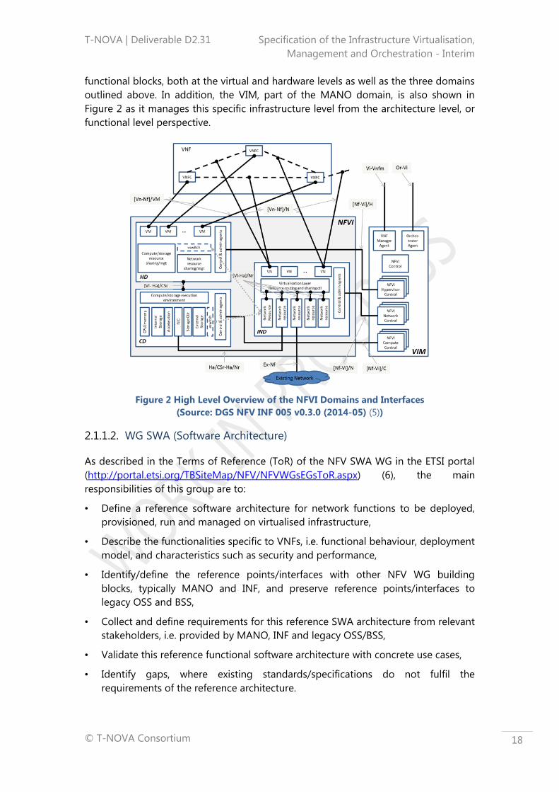
functional blocks, both at the virtual and hardware levels as well as the three domains
outlined above. In addition, the VIM, part of the MANO domain, is also shown in
Figure 2 as it manages this specific infrastructure level from the architecture level, or
functional level perspective.
Figure 2 High Level Overview of the NFVI Domains and Interfaces
(Source: DGS NFV INF 005 v0.3.0 (2014-05) (5))
2.1.1.2. WG SWA (Software Architecture)
As described in the Terms of Reference (ToR) of the NFV SWA WG in the ETSI portal
(http://portal.etsi.org/TBSiteMap/NFV/NFVWGsEGsToR.aspx) (6), the main
responsibilities of this group are to:
• Define a reference software architecture for network functions to be deployed,
provisioned, run and managed on virtualised infrastructure,
• Describe the functionalities specific to VNFs, i.e. functional behaviour, deployment
model, and characteristics such as security and performance,
• Identify/define the reference points/interfaces with other NFV WG building
blocks, typically MANO and INF, and preserve reference points/interfaces to
legacy OSS and BSS,
• Collect and define requirements for this reference SWA architecture from relevant
stakeholders, i.e. provided by MANO, INF and legacy OSS/BSS,
• Validate this reference functional software architecture with concrete use cases,
• Identify gaps, where existing standards/specifications do not fulfil the
requirements of the reference architecture.

T-NOVA | Deliverable D2.31 Specification of the Infrastructure Virtualisation,
Management and Orchestration - Interim
© T-NOVA Consortium
19
With respect to the architecture, and taking into account that the WG is devoted to
the domain that handles the VNFs and their manager, i.e. the VNF lifecycle, the
detailed architecture is depicted in Figure 3.
Figure 3: SWA Architectural Framework and interfaces types
(Source: DGS NFV SWA 001 v0.2.0 (2014-05) (7))
2.1.1.3. WG MANO (Management and Orchestration Architecture)
The ToRs indicated in the ETSI portal for this WG are to:
• Develop ETSI deliverables on the issues related to the deployment, instantiation,
configuration and management framework of network services based on NFV
infrastructure, focused on:
– abstraction models and Application Programming Interfaces (APIs),
– provisioning and configuration,
– operational management,
– interworking with existing OSS/BSS,
• Provide requirements for orchestration and management,
• Identify gaps in current standards and best practices.
The current working architecture conceived by the NFV MANO WG is shown in Figure
4.

T-NOVA | Deliverable D2.31 Specification of the Infrastructure Virtualisation,
Management and Orchestration - Interim
© T-NOVA Consortium
20
Figure 4: NFV MANO reference architectural framework
(Source: DGS NFV MAN 001 v0.6.3 (2014-09) (8))
2.1.2 ITU-T
2.1.2.1 Virtualisation in ITU-T
The ITU Telecommunication Standardization Sector (ITU-T) has been active in
virtualisation although its specification constitutes part of a broader area designated
by Future Networks, which will be briefly described in the last part of this section.
The framework that characterises virtualisation in ITU-T is described, in order to
indicate the manner in which this technology is being handled. A brief explanation on
the work that is being carried out in the ITU-T as well as other associated areas in of
standardisation is provided.
2.1.2.1.1 The Virtualisation concept
In the ITU-T virtualisation framework, the definition of Network Virtualisation (NV)
associated to a network that enables the creation of Logically Isolated Network
Partitions (LINPs) over shared physical network infrastructures so that multiple
heterogeneous virtual networks can simultaneously coexist over the shared
infrastructures. This includes the aggregation of multiple resources and makes the
aggregated resources appear as a single resource.
As such, NV is seen as a method that allows multiple virtual networks, called LINPs, to
coexist in a single physical network. In order to provide LINPs, physical resources are
partitioned and abstracted as virtual resources and the virtual resources are
interconnected to create an LINP.
The definition of LINP states that it is a network that is composed of multiple virtual
resources which is isolated from other LINPs. Moreover, the term virtual resource, or
logical resource, is related to an independently manageable partition of a physical

T-NOVA | Deliverable D2.31 Specification of the Infrastructure Virtualisation,
Management and Orchestration - Interim
© T-NOVA Consortium
21
resource, which inherits the same characteristics as the physical resource and whose
capability is bound to the capability of the physical resource.
In terms of reference architecture, it is necessary to consider that NV is implemented
introducing a virtualisation layer or an adaptation layer, where the virtualisation layer
creates and manages LINPs. The virtualisation layer is a layer positioned between
physical hardware and the software running on a physical resource. This layer enables
the creation of an isolated partition of the physical resource. Each partition is
designed to accommodate different architectures and applications. Figure 5
illustrates the conceptual or reference architecture of a NV:
Figure 5: Conceptual architecture of network virtualization
(Source: Rec. ITU-T Y3011 (9))
2.1.2.1.2 Problems addressed by VNs
This section lists the problems of current networks that network virtualisation is
expected to address in order to mitigate their impact, according to ITU-T Rec. Y.3011
(9):
Coexistence of multiple networks,
Simplified access to resources,
Flexibility in provisioning,
Evolution.
Physical NW 2
Y.3011(12)_F01
Various services
Virtualnetworks
LINP 1
Virtualresources
LINP 3
Physical NW 1
Physical NW 4
Physical NW 3
Physical resources(router, switch,
hosts, etc.)
LIN
P 3
man
ager
LIN
P 2
man
ager
LIN
P 1
man
ager
Vir
tual re
sourc
esm
anag
er
Physi
cal
NW
4 m
anag
er
Phy
sica
l N
W 3
ma
nage
r
Physi
cal
NW
2 m
anag
er
Phy
sica
l N
W 1
man
ager
LINP 2

T-NOVA | Deliverable D2.31 Specification of the Infrastructure Virtualisation,
Management and Orchestration - Interim
© T-NOVA Consortium
22
2.1.2.1.3 Design and goals of VNs
This section addresses the design goals of realising network virtualisation covering
various aspects such as capabilities, characteristics and some challenging issues, once
again according to ITU-T Rec. Y.3011 (9):
Isolation,
Network abstraction,
Topology awareness and quick reconfiguration,
Performance,
Programmability,
Management,
Mobility,
Wireless.
In addition to the problems, design and goals listed above, the deployment of
virtualised networks should also be taken into account including the impact that
environmental and security issues may have in this context.
2.1.2.1.4 Virtualisation requirements
When considering the evolution of networks, it should be considered that while some
requirements for new networks do not change, other requirements are evolving and
changing, while new requirements may also arise, forcing networks and their
architecture to evolve.
It is, therefore, reasonable to expect that some requirements can be realised by the
new network architectures and supporting technologies, and that these could be the
foundation of networks of the future, whose trial services and phased deployment
ITU-T estimates to fall approximately between 2015 and 2020.
This target date does not mean that a network will change by that estimated
timeframe, but that parts of a network are expected to evolve. Evolution and
migration strategies may be employed to accommodate emerging and future
network technologies. Such evolution and migration scenarios are topics for further
study.
In the following, a list of the requirements identified by ITU-T in ITU-T Rec. Y3012 (10)
will be indicated:
Physical resource management,
Virtual resource management,
LINP management,
Service management,
Authentication, authorisation, and accounting,
LINP federation,
Service Mobility.

T-NOVA | Deliverable D2.31 Specification of the Infrastructure Virtualisation,
Management and Orchestration - Interim
© T-NOVA Consortium
23
Again, in addition to the handling of these virtualised requirements, the deployment
of virtualized networks should also be taken into account the impact that
environmental and security issues may have in this context.
2.1.2.2 Work carried out by ITU-T SG13
This section outlines the status of the work that has been carried out in ITU-T, and in
particular in Study Group 13 (SG13), which has held responsibility for virtualisation
since 2009.
As stated before, the virtualisation technology doesn’t constitute a standalone area,
instead it is included in a broader scope designated by Future Networks (FNs).
In the following subsections, FNs are briefly described, in terms of their formal
definition, objectives, design and goals. Finally the attributes that characterise NV are
discussed in order to determine their suitability for deployment in FNs.
2.1.2.2.1 Future Networks
According to ITU-T Rec. Y.3011 (9), FNs are networks that will be able to provide
revolutionary services, capabilities, and facilities that are difficult to support using
existing network technologies. One of the basic objectives of FNs is service
awareness. The number and range of services are expected to explode in the coming
years and FNs need to adapt to the surge in the number of services. That surge
makes it difficult to satisfy the requirements of every service on a common network
architecture. However, it is unrealistic to realise heterogeneous network architectures
using multiple physical networks because of the installation, operation, and
maintenance costs.
Therefore one of the key requirements of a FN is to realise diverse services and
heterogeneous network architectures on a common physical network.
Objectives of FNs
The list of the objectives for FNs identified by ITU-T in ITU-T Rec. Y3001 (11)are as
follows:
Service awareness,
Data awareness,
Environmental awareness,
Social and economic awareness.
Design goals of FNs
According to ITU-T Rec. Y3001 (11), the set of design and goals that must be
considered when elaborating specifications for FNs are as follows:
Service diversity,
Functional flexibility,
Virtualisation of resources,
Data access,

T-NOVA | Deliverable D2.31 Specification of the Infrastructure Virtualisation,
Management and Orchestration - Interim
© T-NOVA Consortium
24
Energy consumption,
Service universalisation,
Economic incentives,
Network management,
Mobility,
Optimisation
Identification,
Reliability and security.
Figure 6 shows the relationships between the four objectives outlined in the previous
section and the design goals described above. It should be noted that some design
goals, such as network management, mobility, identification, and reliability and
security, may relate to multiple objectives. Figure 6 shows only the relationships
between a design goal and its most relevant objectives.
Figure 6: Y.3001: Four objectives and twelve design goals of future networks
(Source: Rec. ITU-T Y3001 (11))
Virtualisation as a key candidate technology for deploying FNs
Network virtualisation is a technology that realises isolated and flexible networks in
order to support a broad range of network architectures, services, and users that do
not interfere with others. It also enables the establishment of experimental networks
with greater ease and accelerates research and development on future network
technologies. Therefore, network virtualisation is considered as a key technology for
realising FNs.
FNs should provide a broad range of applications, services, and network
architectures. Network virtualisation is a key technology supporting these goals and
Y.3001(11)_F01
Serviceawareness
Dataawareness
Social andeconomicawareness
Environmentalawareness
Energy consumption
Optimization
Service universalization
Economic incentives
Service diversity
Functional flexibility
Virtualization of resources
Network management
Mobility
Reliability and security
Data access
Identification
T-NOVA | Deliverable D2.31 Specification of the Infrastructure Virtualisation,
Management and Orchestration - Interim
© T-NOVA Consortium
25
enables the creation of logically isolated network partitions over a shared physical
network infrastructure so that multiple heterogeneous virtual networks can
simultaneously coexist over the same infrastructure. It also allows aggregation of
multiple resources and makes the aggregated resources appear as a single resource.
According to ITU-T Rec. Y3011 (10), many key properties of network virtualisation,
such as flexibility, reconfigurability and network abstraction, make network
virtualisation one of the key technologies for FNs.
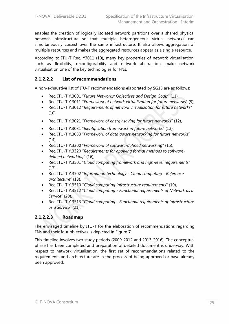
2.1.2.2.2 List of recommendations
A non-exhaustive list of ITU-T recommendations elaborated by SG13 are as follows:
Rec. ITU-T Y.3001 “Future Networks: Objectives and Design Goals” (11),
Rec. ITU-T Y.3011 “Framework of network virtualization for future networks” (9),
Rec. ITU-T Y.3012 “Requirements of network virtualization for future networks”
(10),
Rec. ITU-T Y.3021 “Framework of energy saving for future networks” (12),
Rec. ITU-T Y.3031 “Identification framework in future networks” (13),
Rec. ITU-T Y.3033 “Framework of data aware networking for future networks”
(14),
Rec. ITU-T Y.3300 “Framework of software-defined networking” (15),
Rec. ITU-T Y.3320 “Requirements for applying formal methods to software-
defined networking” (16),
Rec. ITU-T Y.3501 “Cloud computing framework and high-level requirements”
(17),
Rec. ITU-T Y.3502 “Information technology - Cloud computing - Reference
architecture” (18),
Rec. ITU-T Y.3510 “Cloud computing infrastructure requirements” (19),
Rec. ITU-T Y.3512 “Cloud computing - Functional requirements of Network as a
Service” (20),
Rec. ITU-T Y.3513 “Cloud computing - Functional requirements of Infrastructure
as a Service” (21).
2.1.2.2.3 Roadmap
The envisaged timeline by ITU-T for the elaboration of recommendations regarding
FNs and their four objectives is depicted in Figure 7.
This timeline involves two study periods (2009-2012 and 2013-2016). The conceptual
phase has been completed and preparation of detailed document is underway. With
respect to network virtualisation, the first set of recommendations related to the
requirements and architecture are in the process of being approved or have already
been approved.

T-NOVA | Deliverable D2.31 Specification of the Infrastructure Virtualisation,
Management and Orchestration - Interim
© T-NOVA Consortium
26
Figure 7: ITU-T Future networks activity timeline (Roadmap)
(Source: ETSI 3rd
Future Networks Workshop (22))
2.1.3 IETF
2.1.3.1 NETCONF
NETCONF is designed to be a replacement for Command Line Interface (CLI) based
programmatic interfaces. Network automation is currently blocked by available
approaches where we need to write device specific CLI scripts. The CLI is used by
humans, but increases the complexity and reduces the predictability of the API for
real application usage. NETCONF allows the management console (manager or client)
to issue commands and change configuration of networking devices (NETCONF
agent or server). In this respect, it is somewhat similar to Simple Network
Management Protocol (SNMP), but since it uses Extensible Markup Language (XML),
provides a much richer set of functionality than the simple key/value pairs of SNMP.
It is both session and connection-oriented and uses RPC for protocol operations,
which are encoded in XML. Both the device configuration data, and the protocol
itself, are encoded in XML. In order to exchange NETCONF messages, a client must
first establish a NETCONF session with a server. When a session is established, each
NETCONF peer exchanges a list of its capabilities with the other peer.
2.1.3.2 YANG
YANG is a data modelling language used to model configuration and state data
manipulated by the NETCONF, NETCONF remote procedure calls, and NETCONF
notifications in a “human readable” format (23).

T-NOVA | Deliverable D2.31 Specification of the Infrastructure Virtualisation,
Management and Orchestration - Interim
© T-NOVA Consortium
27
YANG is used to model both configuration and state data of network elements. YANG
structures the data definitions into tree structures and provides many modelling
features, including an extensible type system, formal separation of state and
configuration data and a variety of syntactic and semantic constraints. YANG data
definitions are contained in modules and provide a strong set of features for
extensibility and reuse.
2.1.4 TMF – ZOOM
The TM Forum has initiated a project to create a living blueprint for a new generation
of service provider support systems to deliver true business agility and expert
guidance on how to navigate the complexity of the journey– project Zero-touch
Orchestration, Operations & Management (ZOOM).
ZOOM specifically targets business agility by defining a framework that enables the
delivery and management of physical and virtual resources and services while
simultaneously dramatically lowering associated capital and operational expenditures.
This necessitates a new architecture that supports dynamic adaptation between
changing needs and the capabilities of the infrastructure, enabling targeted and
personalised services to be rapidly created, changed, and retired. ZOOM leverages
the capabilities of NFV and SDN.
The main benefits of the ZOOM project are (24):
Zero-touch, self-service operations that can respond with the speed and
agility to outpace competitors;
Adaptive automation, where changes in user needs, business goals, and/or
environmental conditions are recognised, and a new, agile OSS uses these
inputs to provide the resources and services needed at that point in time;
Customer-centric services that are easily configured to fit individual customer
preferences and requirements, by the customer themselves;
Significantly lower operating costs and capital expenses achieved through
automation of manual tasks, simplification of configuration, virtualisation and
use of commodity-based resources;
Technology-driven innovation, where business agility meets rapid
development and experimentation and enables the transition from NetOps
and SysOps to DevOps.
Three main Working Items (WIs) are under the scope of ZOOM (25):
DevOps Transformation Framework for the Digital Ecosystem;
Blueprint for End-to-End Management;
Operations & Procurement Readiness.
The DevOps Transformation Framework for the Digital Ecosystem WI is focused
on clarifying the requirements for a digital world in terms of approaches to hybrid
and virtualised operations, specifically outlining how to transform from

T-NOVA | Deliverable D2.31 Specification of the Infrastructure Virtualisation,
Management and Orchestration - Interim
© T-NOVA Consortium
28
SysOps/NetOps to an agile DevOps approach to introduce new services that make it
possible to better compete in a digital world.
The Blueprint for End-to-End Management will define the essential requirements
for effective management of physical and virtualised services end-to-end across
multiple provider environments, specifically outlining how to make end-to-end
management happen and what common practices, architectural and integration
principles are needed to get there.
The Operations & Procurement Readiness WI will identify the key requirements –
including technical, business, organizational, and cultural changes – necessary for
service providers to include when sourcing agile services in a hybrid environment,
specifically outlining how to best adhere to these requirements throughout the full
sourcing lifecycle. This will help meet the NFV promise of service agility, Operational
Expenditure (OPEX) reductions (NetOps to DevOps), and Capital Expenditure (CAPEX)
reductions (migration from specialised and expensive telco hardware to standard
low-cost IT fabric).
At the time of writing this document, the TMF ZOOM group has released three
documents, namely:
TR227: TM Forum Specifications relevant to MANO Work (26).
The contents provide a description of the set of TM Forum documents that
are relevant to MANO related activities. It identifies areas where each TM
Forum document can help standardise the information presented and the
interfaces of the MANO reference points.
TR228: TM Forum GAP Analysis related to MANO Work (27).
The contents provide an initial ETSI NFV MANO Gap Analysis of the TM Forum
specifications for MANO Interfaces and Information Elements.
TR229: ZOOM/NFV User Stories (24).
This technical report provides a snapshot of the User Stories that have been
identified by the ZOOM project team and have been derived from:
- Scenarios being developed in The TM Forum NFV Catalyst program;
- Requirements in ETSI and ATIS Reports;
- Agile brainstorming sessions amongst Service Providers active in the
ZOOM Project.
2.1.5 CloudNFV
CloudNFV is an industry lead initiative that is focused on the design of an open,
highly flexible, cloud-driven implementation of the ETSI NFV specification, and
secondly to develop an implementation of that design. The founding members of
CloudNFV are 6WIND, CIMI Corporation, Dell, EnterpriseWeb, Overture Networks and
Qosmos. CloudNFV has delivered a number of public demos during the 2014
including the OpenStack Summit in Atlanta.

T-NOVA | Deliverable D2.31 Specification of the Infrastructure Virtualisation,
Management and Orchestration - Interim
© T-NOVA Consortium
29
CloudNFV is based around the concept of an Active Contract that utilises service
templates representing the structures of network functionality, which can be ordered,
and includes variable parameters such as service locations, QoS, etc. When these
values are specified, a Service Contract is created. The service contract is then
dispatched to an Orchestrator for fulfilment. Policy rules and resource status from
Active Resources (as shown in Figure 8) are used by the Orchestrator to determine
the optimal location for the deployment of a VNF service and how to provide
appropriate connectivity.
This combination of where to host and how to connect instructions is known as a
Manifest. The manifest is given to OpenStack, which uses NOVA compute and
Neutron APIs to create VMs, provision network connectivity to the VMs and to deploy
the VNF service. When virtual resources are deployed and connected they report their
status and traffic to the Active Resource. Management processes can run against the
Active Resource, which can take the form of a Multifunctional Information
Distribution System (MIDS) that support current management systems or can be
implementation specific depending on the customer requirements.
Virtual management states are derived from the status of the hosts and networks.
This approach represents what CloudNFV designates by contract resource
management. The data model of the Active Contract is structured in a manner to
reflect the TMF SID (GB922) (28) description of services and forms the basis for
CloudNFV vision for contract-driven management.
Figure 8: The CloudNFV Architecture (29)

T-NOVA | Deliverable D2.31 Specification of the Infrastructure Virtualisation,
Management and Orchestration - Interim
© T-NOVA Consortium
30
2.2 VIM and Control specific areas
The following sections review the key virtualisation technologies that are relevant to
the T-NOVA virtualised infrastructure management and control capabilities together
with their respective pros and cons. While not exhaustive the focus is on the leading
candidate technologies, which will be most likely adopted during the implementation
tasks in WP3 and WP4. A mapping of the technologies and their relationship to
architectural components within the T-NOVA IVM is presented in Figure 9. The
candidate technologies represent an initial starting point, however it is expected that
these technologies choices will evolve and be refined during the course of the T-
NOVA project as new technology options emerge or as candidate technologies are
found to be insufficient to meet the needs of the T-NOVA implementation or prove
to be difficult to extent in an appropriate manner.
Figure 9: Relation between virtualisation technologies and T-NOVA architecture
2.2.1 IT Virtualisation Methods
There are two primary methods commonly used nowadays to implement
virtualisation: hypervisors and containers. The former is based on the usage of a
Virtual Machine Monitor, whereas the latter is an operating system virtualisation
mechanism, where the virtualisation software layer is installed on top of the operating
system. The following sections will look both of these approaches in more detail.

T-NOVA | Deliverable D2.31 Specification of the Infrastructure Virtualisation,
Management and Orchestration - Interim
© T-NOVA Consortium
31
2.2.1.1 Hypervisors
A hypervisor is a program that allows multiple operating systems to share the same
hardware. By “virtualise”, we mean the division of resources (CPU, RAM etc.) in the
physical computing environment (known as a host) into several smaller independent
‘virtual machines’ known as guests. Each guest can run its own operating system, to
which it appears the virtual machine has its own CPU and RAM, i.e. it appears as if it
has its own physical machine even though it does not.
One of the key functions of hypervisors is isolation, meaning that a guest cannot
affect the operation of the host or any other guest, in any case. This is achieved by
hardware emulation of a physical machine and (except under carefully controlled
circumstances) prevention of direct access to real hardware by the guests.
Hypervisor can be classified using different taxonomies.
One approach is centred on the virtualisation approach used by the hypervisor. Three
main approaches can be used to implement virtualisation:
Full virtualisation - the hypervisor artificially emulates the hardware device with
everything it needs to run an operating system. This allows VMs to run in a single
server, each completely independent of the other. The drawback is the addition of
another layer of software between the operating system and the hardware which can
negatively influence performance,
Para-virtualisation – the hypervisor modifies the VM OS eliminating the need
for binary translation. It offers potential performance advantages, but requires
the use of specially modified operating system kernels that relies on ‘para-
virtualised drivers’ (an optimised interface to the hardware for the hypervisor
is provided). This approach is generally only suited to Open Source OSs, (i.e.
Linux and FreeBSD),
Hardware-assisted virtualisation – The underlying hardware has to provide
specific instructions for virtualisation support to the hypervisor. This provides
a simpler and a better solution in terms of performance in comparison to
other solutions, giving direct access to resources without emulation.
Another taxonomy approach relates to the type of hypervisor. There are two types of
hypervisors, namely Type 1 and Type 2:
Type 1 hypervisors run directly on the system hardware, and are often
referred to as a "native" or "bare metal" or "embedded" hypervisors. Each
guest operating system runs atop the hypervisor. Examples of Type 1
hypervisors are: VMware ESXi, Microsoft Hyper-V, Citrix XenServer and KVM1,
Type 2 hypervisors (also called ‘Hosted’ hypervisors) run inside an operating
system, which in turn runs on the physical hardware. Each guest operating
system then runs atop the hypervisor. Desktop virtualisation systems often
1There is considerable debate over whether KVM is a type 1 or type 2 hypervisor
http://searchservervirtualization.techtarget.com/news/2240034817/KVM-reignites-Type-1-vs-
Type-2-hypervisor-debate
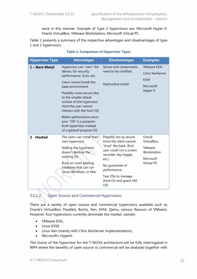
T-NOVA | Deliverable D2.31 Specification of the Infrastructure Virtualisation,
Management and Orchestration - Interim
© T-NOVA Consortium
32
work in this manner. Example of Type 2 hypervisors are: Microsoft Hyper-V,
Oracle VirtualBox, VMware Workstation, Microsoft Virtual PC.
Table 1 presents a summary of the respective advantages and disadvantages of type
1 and 2 hypervisors.
Table 1: Comparison of Hypervisor Types
Hypervisor Type Advantages Disadvantages Examples
1 – Bare Metal Hypervisor can “own” the
device, for security,
performance, SLAs, etc.
Users cannot break the
base environment
Possibly more secure due
to the smaller attack
surface of the hypervisor
(And the user cannot
interact with the host OS)
Better performance since
your “OS” is a purpose-
built hypervisor instead
of a general purpose OS
Server and components
need to be certified.
Destructive install
VMware ESXi
Citrix XenServer
KVM
Microsoft
Hyper-V
2 - Hosted The users can install their
own hypervisor
Adding the hypervisor
doesn’t destroy the
existing OS
Runs on most existing
hardware that can run
Linux, Windows, or Mac
Possibly not as secure
since the client cannot
“trust” the base. (End
user could run a screen
recorder, key logger,
etc.)
No guarantee of
performance.
Two OSs to manage
(host OS and guest VM
OS)
Oracle
VirtualBox,
VMware
Workstation
Microsoft
Virtual PC
2.2.1.2 Open Source and Commercial Hypervisors
There are a variety of open source and commercial hypervisors available such as
Oracle's VirtualBox, Parallels, Bochs, Xen, KVM, Qemu, various flavours of VMware.
However, four hypervisors currently dominate the market, namely:
VMware ESXi,
Linux KVM,
Linux Xen (mainly with Citrix XenServer implementation),
Microsoft's HyperV.
The choice of the hypervisor for the T-NOVA architecture will be fully interrogated in
WP4 where the benefits of open source vs commercial will be analysed together with
T-NOVA | Deliverable D2.31 Specification of the Infrastructure Virtualisation,
Management and Orchestration - Interim
© T-NOVA Consortium
33
the level of integrated with the chosen cloud platform.. The next sections present a
short overview of the key hypervisor technologies.
KVM
KVM can run unmodified Linux or Windows images, but it
requires CPU virtualisation extensions (Intel VT or AMD-V). It
consists of a loadable kernel module, that provides the core
virtualisation infrastructure, and a processor-specific module.
KVM is used in conjunction with Qemu to emulate other hardware such as network
card, hard disk, graphics adapter, etc. Qemu can be used in standalone mode (i.e.
does not require a special kernel module, or CPU virtualisation extensions, or a
hypervisor layer) and is capable of running unmodified operating system images.
KVM and Qemu are normally used with libvirt, a C library for interfacing with the
underlying virtual machines, that provides a stable, consistent API for machine
management across a variety of virtualisation technologies and currently supports
Xen, Qemu, KVM, User Mode Linux and VirtualBox, among others. Libvirt uses XML-
based configuration files to define the virtualised hardware. Libvirt is also used by the
libvirtd daemon, used to mediate communication with the virtualisation system.
XEN
Xen dates back to a Cambridge University research project
in 2003. Since it is a Type 1 hypervisor, its ‘dom0’ host runs
on Linux, which in turn runs on Xen. The Xen community
develops and maintains Xen as free and open-source
software under GNU GPL licence. In 2013, it was announced that the Xen Project was
moving to the Linux Foundation as a Collaborative Project. Key features include: small
footprint and interface; operating system agnostic; driver isolation (it allows the main
device driver for a system to run inside of a VM so that if the driver crashes, the VM
containing the driver can be rebooted without affecting the rest of the system) and
compatibility with hardware that doesn't support virtualisation extensions.
vmware
VMware’s ESXi hypervisor is very mature and
extremely stable. It is popular among enterprise
customers including many telco service providers
where brand and the commercial guarantee of a rock
solid hypervisor matters more than cost. The performance level of ESXi is similar
other hypervisors for most workloads. However the orchestration performance is
generally worse than either KVM or Xen (30). vSphere was developed as an enhanced
suite of tools for cloud computing utilising VMware ESX/ESXi hypervisors. Some key
components of this platform are: vMotion and Storage vMotion (for live migration of
respectively VMs and vDisks); VMware High Availability (automatic restart of the VMs
if the underling hardware goes down); DRS (Distributed Resource Scheduling for VM
placement at the VM provisioning and VMs balancing among hosts; both can be
manually or automatically done) and SDRS (Storage DRS); Fault Tolerance (a more
powerful High Availability (HA) that runs in real time a mirrored VM); Distributed

T-NOVA | Deliverable D2.31 Specification of the Infrastructure Virtualisation,
Management and Orchestration - Interim
© T-NOVA Consortium
34
Power Management and VMware Consolidated Backup (for both energy efficiency and
data consolidation) and SRM (Site Recovery Manager, that manages a full failover
and failback of a disaster event from a centralised console. Additionally full disaster
simulation and testing is supported without interrupting the production
environment).
Hyper-V
Hyper-V is a commercial hypervisor provided by
Microsoft. While designed for running Windows, being a
hypervisor it will run any operating system supported by
the hardware platform. As a commercial hypervisor, the
licensee must bear the cost of licensing Hyper-V itself. Arguably, the hypervisor itself
is less well tested in the market place than any other hypervisor. Guest server
performance appears reasonable, and is particularly good with Windows guests as
expected. However, many orchestration actions can take more time than with KVM.
Both networking and storage are a little limited which can affect the ability to scale.
Until recently it has rarely been adopted for large deployments in enterprise
environments although it has been used widely in small and medium business
environments for a number of years.
Table 2 compares the hypervisors discussed above.
Table 2: Comparison of key open source and commercial hypervisor technologies
Feature KVM Xen ESXi Hyper-V
Licence Open Source (free) Open Source
(free)
Proprietary Proprietary
Full virtual. yes yes yes yes
Hw-assisted no yes yes yes
Para-virtual. no yes yes yes
Architecture X86-X64 X86
X86-64
ARM
X86
X86-64
X86
X86-64
CPU
Scheduling
Features
Linux schedulers
(completely fair
queuing scheduler,
maximum
throughput,
weighted fair
queuing)
SEDF (Simple
Earliest Deadline
First)
Credit -
proportional fair
share
Proportional
Share-based
Algorithm,
Relaxed
Coscheduling,
Distributed
Locking with
scheduling Cell
Control with
VM reserve,
VM limit,
relative
weight
SMP
Scheduling
Features
SMP-Aware
Scheduling
Work-
Nonconserve,
WorkConserve
CPU Topology –
aware load
balancing
CPU
Topology
based
scheduling
Speed Up to near native Up to native Up to near native Up to near

T-NOVA | Deliverable D2.31 Specification of the Infrastructure Virtualisation,
Management and Orchestration - Interim
© T-NOVA Consortium
35
Relative to
Host OS
native
2.2.1.3 Containers
The alternative approach to hypervisor-based virtualisation is OS virtualisation, where
the virtualisation software layer is installed on top of the operating system. This
approach is commonly referred to as “containers”. Figure 10 provides a high-level
view of the differences between container-based and hypervisor-based virtualisation.
One of the most popular container technologies is Docker (31). All of the guest
systems run on top of this layer using the same operating system as the host OS, but
with each guest having its own resources and running in complete isolation from the
other guest machines. The main identifying differentiator for OS virtualisation is the
fact that every guest OS must be identical to the host. This is a cost effective and
efficient approach, but it is only practical for certain situations.
Figure 10: Hypervisor versus container based virtualisation approaches
However containers currently lag behind VMs from a security standpoint particularly
for isolation since the only way to have real isolation with Docker is to either run one
Docker per host, or one Docker per VM. A comparison of the hypervisor versus
container based virtualisation approaches is presented in Table 3.
Table 3: Comparison of Hypervisors and Container Approaches
Container-based Hypervisor-based
Common Features (i) Migration between hardware nodes

T-NOVA | Deliverable D2.31 Specification of the Infrastructure Virtualisation,
Management and Orchestration - Interim
© T-NOVA Consortium
36
(ii) Root access
(iii) Web-based remote control (restart, shutdown)
(iv) Backup.
Operating System
Limited number of simultaneously
OSs, container-based
virtualisation.
Highly flexible and allows
installation of most operating
system.
Advantages
More efficient, high concentration
of containers per hardware node
(hundreds of containers per
hardware node), low overhead per
container.
Potentially more economical and
is charged less than hypervisor-
based virtualisation.
QOS is best effort.
The kernel is upgraded by the
provider.
Full control on the operating
system and its parameters.
Full control on version and
upgrade of the OS.
Hardware resources are fully
dedicated to VMs. QoS (quality of
service) is therefore a
commitment. The virtual machine
presents itself exactly as a
hardware node.
Mix of operating system on the
same hardware node.
Disadvantages
No control on the kernel: only the
provider controls the version and
upgrades of the kernel.
Only one kernel can run on the
hardware node.
The provider generally supports a
limited number of OS.
Security isolation concerns.
More costly and higher overhead
per virtual machine.
Customer has full responsibility on
maintenance.
Less VMs can run on a hardware
node (order of magnitude: a few
per hardware node).
Licence
Operating system licence included
in the container price.
OS licence fees not included in the
virtual machine price.
It can be bought over the provider
or bring your own licence.
Set-up
Quick, usually ready in a few
seconds.
Fully automation possible.
Can have a longer set-up phase,
from a few minutes to hours
depending on the OS. Install times
reduced with automation in cloud
environments.
2.2.2 Compute, Network I/O and Storage Virtualisation
Virtualisation has now extended into the domains of storage and infrastructure
(L2/L3) network resources. Storage virtualisation is replacing the need for locally
attached storage through pooling of physical storage from multiple network storage
devices into what appears to be a single storage device that is accessed via a
controller. Similarly with network I/O virtualisation, a single physical network interface

T-NOVA | Deliverable D2.31 Specification of the Infrastructure Virtualisation,
Management and Orchestration - Interim
© T-NOVA Consortium
37
card can be abstracted into virtual NICs or L2 virtual switching and L3 virtual routing
to provide inter/intra-VM connectivity or connectivity to the transport network.
The key value that virtualisation brings to those new domains is improved scalability
and resource utilisation. Additionally, virtualisation supports the centralisation of
administrative tasks such day-to-day updates or large-scale deployments and
migrations. These capabilities are very important in enabling the roll-out of VNFs into
networks by service providers.
2.2.2.1 Microprocessor Virtualisation
Microprocessor virtualisation extensions consist of extra instruction sets called virtual
machine extensions (VMX). There are two modes to run under virtualisation: VMX root
operation and VMX non-root operation. Normally only the hypervisor runs under root
operation, while OS’s run on top of the VMs under non-root operation. Software
running on top of the VMs is commonly referred to as ‘guest software’.
More recent microprocessors have an extension called EPT (Extended Page Tables)
which allow each guest to have its own page table to keep track of memory
addresses. Without this extension, the VMM has to exit the virtual machine to
perform address translation. The exiting-and-returning task reduces performance.
Context switching and its associated cost can have a significant impact on the
performance of VNF applications. While EPT increases virtualisation performance,
careful consideration must be given to overall design of the VNF.
2.2.2.2 Intel Virtualisation Technology (Intel VT)
Intel Virtualisation Technology (Intel VT) is a set of hardware enhancements to Intel
server and client platforms that provide software-based virtualisation solutions. Intel
VT allows a platform to run multiple operating systems and applications in
independent partitions, allowing one computer system to function as multiple virtual
systems. VT-x provides basic support for virtualisation software and affords the
capabilities needed to deliver hardware assistance to a VMM. VT-x allows virtual
machine to run at privilege levels in the processor that enable its proper operation.
On some motherboards the VT-x feature must be enabled in the BIOS before
applications can make use of it.
2.2.2.3 AMD's Virtualisation (AMD-V) Opteron
AMD's Virtualisation (AMD-V) technology takes some tasks that virtual machine
managers (VMMs) perform in software, through emulation, and simplifies them
through enhancements to the AMD Athlon 64 and Opteron instruction set. AMD
Virtualisation Technology was announced in 2004, under the code-name Pacifica, and
AMD released technical details in mid-2005. The latest release AMD-V 2.0 includes
extra features, such as I/O level Virtualisation, and Extended Migration. AMD-V is
supported in almost all latest AMD mobile and desktop processors, whereas AMD V
supported only in the latest generation of AMD server-class CPUs.

T-NOVA | Deliverable D2.31 Specification of the Infrastructure Virtualisation,
Management and Orchestration - Interim
© T-NOVA Consortium
38
2.2.2.4 Storage Virtualisation
Storage virtualisation consists in implementing an abstraction layer between physical
resources (disks and storage networking) and logical resources that can be served up
to applications (VNFs in case of T-NOVA). Multiple benefits are offered by virtual
storage. It makes the overall pool of storage easier to manage, and enables the
allocation of storage as and when it is needed. Furthermore, it can optimise power
utilisation, and improves the ability to support disaster recovery scenarios, as data
can be replicated and moved within the overall storage pool with minimum
disruption to users and applications.
Storage virtualisation can occur internally within storage arrays (usually known as
storage-based virtualisation), or externally among storage arrays (usually called
network-based storage virtualisation). External virtualisation can operate across arrays
of the same brand and model or in a network of heterogeneous arrays. External
virtualisation can facilitate tiered storage to disparate devices as well as providing
simplified management of storage across a large enterprise. Implementation choices
should take into account the characteristics of the whole virtualised environment,
since there are different underlying technologies whose effectiveness and
performance can depend upon the kind of server virtualisation environment in place.
The most common enabling technologies are as follows:
Thin Provisioning - storage-optimisation technique that relies on on-
demand allocation of blocks of data, rather than on traditional upfront block
allocation. This approach makes it possible to implement over-allocation,
storage capacity to host applications than has actually been provisioned). It
may be paired with other techniques, like thin reclamation and data de-
duplication. Thin reclamation automatically reclaim unused space associated
with deleted data within system storage volumes, while data de-duplication is
a data compression technique for eliminating duplicate copies of redundant
data. Both techniques ensure that thin volumes stay as lean and efficient as
possible. These techniques are popular and integrated in many enterprise
storage array products from companies such as HP, 3PAR, and EMC, VNX (32).
Automatic Storage Tiering - this approach is based on the ability to save
data on different tiers of disks, each characterised by different performance
and redundancy schemes. For example, a typical 2-tier array could have SSD
disks as Tier 0 and SAS disks as Tier 1. Automatic Storage Tiering is a
technique used to automatically promote or demote data between storage
tiers, based on actual application usage. Many storage vendors (e.g. HP with
3PAR Adaptive Optimisation (33) and EMC with its FAST technology (34))
nowadays implement automatic storage tiering in hardware.
Virtual SAN solutions - For many years, local storage was not the best
option for virtualised infrastructures, however due to technology advances
and, in particular, the introduction of Solid State Disks, it can now be used as
an effective and cheaper solution with respect to standard NAS or SAN
enterprise solutions. Moreover, software vendors have introduced

T-NOVA | Deliverable D2.31 Specification of the Infrastructure Virtualisation,
Management and Orchestration - Interim
© T-NOVA Consortium
39
functionality to use shared local storage into a fully-featured shared storage
array, for example VMware Virtual SAN and HP StoreVirtual VSA.
2.2.2.5 Software and Hardware -Assisted Network Virtualisation
The Network Virtualisation process strongly involves the lower levels of the ISO/OSI
protocol stack: virtual machines require L2 NICs to connect to virtual network
segments; all the VMs in a segment need to connect to one or more (virtual) switches
that manage different VLANs.
Two main approaches are commonly used to implement virtualisation at the edge of
the network: software-assisted and hardware-assisted virtualisation.
Software-assisted network virtualisation
In software-assisted network virtualisation, communication capabilities are provided
by the hypervisor through vSwitches, according to the Edge Virtual Bridging (EVB)
specifications. More specifically, Edge Virtual Bridging is the term for a range of new
technologies and protocols that are being standardised in terms of coordination and
management of virtualised architectures at the edge of the network. A vSwitch is a
software component managed by the hypervisor that, in turn, manages both the
traffic flows from and to VMs that are running on a physical server. EVB technologies
are embraced within the IEEE 802.1Qbg standardisation project (35). The two most
common approaches included in EVB and currently used in commercial available
technologies are:
Virtual Ethernet Bridge (VEB),
Virtual Ethernet Port Aggregator (VEPA).
External communications (i.e. the communication between a VM and an external
node) are managed by both VEB and VEPA in the same way: packets are sent through
the physical interface of hosting node to reach external network. This allows the
traffic to be handled by an external physical switch and, consequently, to be
monitored, managed and secured using all the tools available to the physical switch.
The difference between VEB and VEPA is related to the management of internal
communication (i.e. the communication between VMs running on the same physical
host).
Figure 11: VEB vs. VEPA
VM1 VM2 VM3
vNIC vNIC vNIC
Adjacentswitch
ExternalCommunication
InternalCommunication
VEB
NIC
Hypervisor
VM1 VM2 VM3
vNIC vNIC vNIC
VEPA
NIC
Adjacentswitch
ExternalCommunication
InternalCommunication
Hypervisor

T-NOVA | Deliverable D2.31 Specification of the Infrastructure Virtualisation,
Management and Orchestration - Interim
© T-NOVA Consortium
40
Using the first approach, internal communications are managed directly by the VEB
that resolves the L2 destination address of the target machine and avoids sending
traffic through external switches. Consequently, the internal traffic is managed only
by software, and, for this reason, it is not captured by the external network devices:
this makes network traffic monitoring difficult and, at the same time, delegates to the
host the network address resolution overhead, affecting the performance. On the
contrary, VEPA forces the traffic between local VMs to pass through the adjacent real
switch. Therefore, using this approach the traffic can be easily monitored and
secured, reducing the node overhead. On the other hand, the internal traffic uses the
physical port, with impacts to bandwidth and latency as a result.
Hardware-assisted network virtualisation
The disadvantage of a software-assisted approach is that, when multiple guests run
on the host and the network traffic volumes are high, the virtual switch can be a
potential bottleneck. To avoid this, multiple NICs should be used in the host,
adjusting the virtual switch connected to each NIC such that the network bandwidth
used by the guest can be distributed. However, this method is not particularly
efficient for some tasks, such as placing guests dynamically and moving a guest to
another host using live migration. To address these limitations Intel has developed its
VT-c suite of technologies.
Single Root I/O Virtualisation (SR-IOV) enables a single PCI Express (PCIe) network
adapter to appear to the hypervisor as multiple special-purpose network adapters.
These special-purpose network adapters, termed Virtual Functions (VF), are only
available for direct presentation to VMs. By providing a VF directly to a VM, the
hypervisor’s virtual switch is no longer required to process network traffic. This
hypervisor bypass increases network throughput, lowers latency, and reduces overall
CPU utilisation.
Network adapters that feature SR-IOV are comprised of one Physical Function (PF)
and multiple VFs per port. The PF is responsible for the management and
configuration of its associated VFs. On the host server, the administrator configures a
PF to present a defined number of VFs.
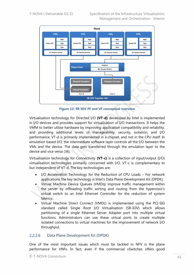
T-NOVA | Deliverable D2.31 Specification of the Infrastructure Virtualisation,
Management and Orchestration - Interim
© T-NOVA Consortium
41
Figure 12: SR-IOV PF and VF conceptual overview
Virtualisation technology for Directed I/O (VT-d) developed by Intel is implemented
in I/O devices and provides support for virtualisation of I/O transactions. It helps the
VMM to better utilise hardware by improving application compatibility and reliability,
and providing additional levels of manageability, security, isolation, and I/O
performance. VT-d is primarily implemented in a chipset, and not in the CPU itself. In
emulation based I/O, the intermediate software layer controls all the I/O between the
VMs and the device. The data gets transferred through the emulation layer to the
device and vice versa (36).
Virtualisation technology for Connectivity (VT-c) is a collection of input/output (I/O)
virtualisation technologies primarily concerned with I/O. VT-c is complementary to
but independent of VT-d. The key technologies are:
I/O Acceleration Technology for the Reduction of CPU Loads – For network
applications the key technology is Intel’s Data Plane Development Kit (DPDK);
Virtual Machine Device Queues (VMDq) improve traffic management within
the server by offloading traffic sorting and routing from the hypervisor’s
virtual switch to an Intel Ethernet Controller for the reduction of system
latency;
Virtual Machine Direct Connect (VMDc) is implemented using the PCI-SIG
standard called Single Root I/O Virtualisation (SR-IOV) which allows
partitioning of a single Ethernet Server Adapter port into multiple virtual
functions. Administrators can use these virtual ports to create multiple
isolated connections to virtual machines for the improvement of network I/O
throughput.
2.2.2.6 Data Plane Development Kit (DPDK)
One of the most important issues which must be tackled in NFV is the plane
performance for VNFs. In fact, even if the commercial vSwitches offers good

T-NOVA | Deliverable D2.31 Specification of the Infrastructure Virtualisation,
Management and Orchestration - Interim
© T-NOVA Consortium
42
performance, they are generally not comparable with real network device. To enable
VNFs to be efficiently deployed and provide the performance that support their
requirements the internal mechanisms for communication management within
hypervisors are being improving.
One approach that is being widely adopted is Intel’s Data Plane Development Kit
(Intel DPDK). It is a set of libraries and drivers for fast packet processing on x86
platforms that can improve packet-processing performance by up to ten times. DPDK
support, which actually depends on the processor, is integrated in all recent Intel
Atom and Xeon processors.
In order to accelerate the adoption of DPDK and its usage in NFV deployments, Intel
also released a DPDK-enabled version of the popular OpenvSwitch, called Intel DPDK
vSwitch (37). Open vSwitch (38) is an open source virtual switch that supports
distribution across multiple physical servers. It can be integrated with multiple Linux-
based hypervisors (including Xen, XenServer, KVM and VirtualBox) and supports
different features, like STP, NIC bonding with source MAC load balancing, IPv6
support, standard 802.1Q VLAN tagging and trunking, tunnelling protocols (GRE,
VXLAN, IPsec), monitoring capabilities of internal VM communication via NetFlow or
sFlow, QoS control, OpenFlow protocol and multi-table forwarding pipeline, and
user-space forwarding engine options, and so forth.
Open vSwitch architecture is composed by a small portion of in-kernel code, a kernel
module called openvswitch_mod.ko, which implements the part of the behaviour of
switch that interacts with the ovs-vswitchd demon, running in user-space. These
modules implement the switching logic. Moreover, there is also another module,
called ovsdb-server, which behaves as a lightweight database containing information
regarding the configuration parameters of the switch and it is queried by the ovs-
vswitchd module. There are also other modules that provide interfaces which are
useful for configuring the system both locally and remotely.
Coupling OpenvSwitch and Intel DPDK acceleration technology, Intel DPDK vSwitch
has been developed with the aim of realising a virtual switching platform with high
performance capabilities, reducing network access time of the VM traffic and the
computation overload on the hypervisor. This specific solution is based on QEMU and
is part of an open source project called Packet Processing (39).
The Intel DPDK vSwitch has been realised through modification of the Open vSwitch
kernel forwarding module (data plane) by building the switching logic directly on top
of the DPDK library: it significantly improves the switching throughput. Intel DPDK
vSwitch currently provides four different communication methods between the virtual
machine and the host (each one optimised for a specific communication application)
with the purpose to optimise the copy operations due to the VMs’ communication.
This product, which is freely available, is currently focused on fast L2 switching, with
more advanced features (like dynamic flows, tunnel support and multiple table
support) coming in later releases.

T-NOVA | Deliverable D2.31 Specification of the Infrastructure Virtualisation,
Management and Orchestration - Interim
© T-NOVA Consortium
43
2.2.3 Cloud Environments and Controllers
Cloud management platforms are integrated tools that provide management of
cloud environments. These tools incorporate self-service interfaces, provisioning of
system images, enabling metering and billing, and providing some degree of
workload optimisation through established policies. Through the self-service interface
(e.g. based on OCCI) the user can request virtual infrastructure. This request is issued
to a Cloud Controller, which provisions this virtual infrastructure somewhere on
available resources within the DC. The Cloud Controller provides the central
management system for cloud deployments as shown in Figure 13.
Figure 13: Cloud Management System Deployments
The most popular cloud management platforms include open source solutions such
as OpenStack, CloudStack and Eucalyptus and commercial solutions from Microsoft
and VMware. This section provides an overview of some of these solutions, on the
Cloud Controller component. In the T-NOVA context, the Cloud Controller is a key
component that needs to deliver end-to-end provisioning of virtual infrastructure, to
enable full control over it and also to provide a detailed and real-time view of the
infrastructure load.
2.2.3.1 OpenStack
OpenStack is a cloud OS that controls large pools of compute,
storage, and networking resources throughout a DC, all managed
through a dashboard that gives administrators control while
empowering their users to provision resources through a web
interface (40; 40). As an open source solution, OpenStack is
developed and supported by a global collaboration of developers
and cloud computing technologists. The project seeks to deliver
solutions for all types of clouds by being simple to implement, scalable, and feature
rich. The technology consists of a series of interrelated projects delivering various
components for a cloud infrastructure solution. All OpenStack source code is
available under an Apache 2.0 license.

T-NOVA | Deliverable D2.31 Specification of the Infrastructure Virtualisation,
Management and Orchestration - Interim
© T-NOVA Consortium
44
OpenStack has a modular design that enables integration with legacy and third-party
technologies. It is built on a shared-nothing, messaging-based architecture with
modular components, each of which manages a different service; these services,
together to instantiate an IaaS Cloud. The primary component of the cloud operating
environment is the Nova compute service. Nova compute orchestrates the creation
and deletion of compute/VM instances. Nova is designed to operate as much as
possible as hypervisor-agnostic. It works with open source libraries such as libvirt.
Similar to other OpenStack components, Nova is based on a modular architectural
design where services can be co-resident on a single host or, more commonly, on
multiple hosts. The core components of Nova include the following:
The nova-api accepts and responds to end-user compute API calls. It also
initiates most of the orchestration activities (such as running an instance) as
well as enforcing some policies.
The nova-compute process is primarily a worker daemon that creates and
terminates VM instances via hypervisor APIs (XenAPI for XenServer/XCP, libvirt
for KVM or QEMU, VMwareAPI for vSphere, etc).
The nova-scheduler process keeps a queue of VM instance requests and for
each request it determines where the VM instance should run (specifically,
which compute node it should run on).
The Nova service itself does not come with a hypervisor, but manages
multiple hypervisors, such as KVM or ESXi. Nova orchestrates these
hypervisors via APIs and drivers. For example, Hyper-V is managed directly by
Nova and KVM is managed via libvirt, while Xen and vSphere can be managed
directly or through management tools such as libvirt and vCenter for vSphere,
respectively.
2.2.3.2 Eucalyptus
Eucalyptus (Elastic Utility Computing Architecture Linking
Your Programs To Useful Systems) is an open-source Cloud
that provides on-demand computing instances and shares
the same APIs as Amazon’s EC2 cloud. Eucalyptus was designed as a highly-modular
framework in order to enable extensibility with minimal effort (41). The Cloud
Controller (CLC) in Eucalyptus acts as the Cloud entry-point by exposing and
managing the virtualised resources. The CLC offers a series of web services oriented
towards resources, data and interfaces (EC2-compatible and Query interfaces). In
addition to handling incoming requests, the CLC acts as the administrative interface
for cloud management and performs high-level resource scheduling and system
accounting. The CLC accepts user API requests from command-line interfaces like
euca2ools or GUI-based tools like the Eucalyptus Management Console and manages
the underlying compute, storage, and network resources.
2.2.3.3 Cloudstack
Apache CloudStack is open source software designed to
deploy and manage large networks of virtual machines, as a
highly available, highly scalable Infrastructure as a Service (IaaS) cloud computing

T-NOVA | Deliverable D2.31 Specification of the Infrastructure Virtualisation,
Management and Orchestration - Interim
© T-NOVA Consortium
45
platform (42). CloudStack is used by a number of service providers (e.g. BT) to offer
public cloud services, and by many companies to provide an on-premises (private)
cloud offering, or as part of a hybrid cloud solution. CloudStack is a turnkey solution
that includes the entire "stack" of features most organisations want with an IaaS
cloud: compute orchestration, Network-as-a-Service, user and account management,
a full and open native API, resource accounting, and a first-class User Interface (UI).
CloudStack is a framework that allows pooling of computing resources in order to
IaaS cloud services that can be used to provide IT infrastructure such as compute
nodes (hosts), networks, and storage as a service to the end users on demand.
CloudStack Management Server is the main component of the framework, consisting
of managing resources such as hosts, storage devices and IP addresses. The
Management Server runs on a dedicated host in a Tomcat container and requires a
MySQL database for persistence. The Management Server controls allocation of VMs
to hosts and assigns storage and IP addresses to VM instances. This component also
controls or collaborates with the hypervisor layers on the physical hosts over the
management network and thus controls the IT infrastructure.
2.2.3.4 VMware vCloud Suite
VMware’s vCloud Suite - is a comprehensive, integrated
cloud platform for building and managing cloud
environments (43). Tools for cloud management are
delivered through VMware vCenter Server, a centralised and extensible platform for
managing virtual infrastructure. The tools included in the vCenter Server framework
support: configuration of ESX servers and VMs, performance monitoring throughout
the entire infrastructure, using events and alerts. The objects in the virtual
infrastructure can be securely managed with roles and permissions.
2.2.4 Network Resource Virtualisation and Management
Virtualising the Network Infrastructure refers to the environment that supports the
coexistence of multiple Virtual Networks (VNs) on the same physical substrate, also
realising different isolated domains of nodes characterised by a specific topology that
can be managed as real networks. In the T-NOVA architecture those nodes are Virtual
Machines (VMs) that host the VNFs. VMs are connected to VLANs that can be within
a single DC or distributed over different DCs. In this last case, tunnelling protocols are
needed in order to encapsulate the VLAN L2 frames in L3 transport networks. In the
T-NOVA architecture the inter-DC connectivity is provided by the Transport Network
Manager (TNM), whose capabilities and functionalities are discussed in Section 4.7.
This section provides an overview of the common Tunnelling Protocols which can be
of interest to T-NOVA, followed by a review of the major SDN initiatives of interested
finally some common open source NaaS frameworks are reviewed.
2.2.4.1 Tunnelling Protocols
As mentioned above, a single physical server may host a number of different VNF
services that need to be connected to different VLANs. Moreover, each of these

T-NOVA | Deliverable D2.31 Specification of the Infrastructure Virtualisation,
Management and Orchestration - Interim
© T-NOVA Consortium
46
VLANs may span several DCs interconnected via L3 networks; all the VMs in a
segment have to be connected to a virtual switch that can manage different VLANs.
The most important standardisation activities carried out on VLAN specification is
802.1Q. This standard however does inherently support the expansion of VLANs over
L3 technologies. The continuity of L2 segments (i.e. VLANs) among different DCs is a
requirement for the T-NOVA architecture. In order to preserve the L2 segments
continuity amongst the NFVI-Point of Presence (NFVI-PoP), tunnelling protocols
(heavily used in today’s cloud services) will be exploited.
In the following subsections a brief introduction to IEEE 802.1Q is presented and the
three most common tunnelling protocols are discussed namely VxLAN (44), Network
Virtualization using Generic Routing Encapsulation (NVGRE) (45) and Stateless
Transport Tunneling (STT) (46).
IEEE 802.1Q and L2 Virtualisation
IEEE 802.1Q is the networking standard that supports virtual LANs (VLANs) on an
Ethernet network. The standard defines a system of VLAN tagging for Ethernet
frames and the accompanying procedures to be used by bridges and switches in
handling these frames. The standard also contains provisions for a quality of service
prioritisation scheme (commonly known as IEEE 802.1p) and defines the Generic
Attribute Registration Protocol.
Network segments, which are VLAN-aware (i.e., IEEE 802.1Q conformant) may include
VLAN tags. Traffic on a VLAN-unaware (i.e., IEEE 802.1D conformant) segment of the
network will not contain VLAN tags. When a frame enters the VLAN-aware segment
of the network, a tag is added to represent the VLAN membership of the frame's port
or the port/protocol combination, depending on whether port-based or port-and-
protocol-based VLAN classification is being used. Each frame must be distinguishable
as being within exactly one VLAN. A frame in the VLAN-aware portion of the network
that does not contain a VLAN tag is assumed to be flowing on the native (or default)
VLAN.
The standard was developed by IEEE 802.1, a working group of the IEEE 802
standards committee, and continues to be actively revised with notable revisions
including IEEE 802.1ak, IEEE 802.1Qat and IEEE 802.1Qay.
In T-NOVA, 802.1q VLANs can be established within a NFVI-PoP, e.g. to facilitate
communication among Virtual Network Function Components (VNFCs) of the same
service.
L3 tunnelling protocols
While L2 virtualisation seems adequate within a single L2 topology, transporting L2
frames via a L3 network (e.g. a wide-area transport network interconnecting data
centres) mandates the use of tunnelling protocols.
The aim of a tunnelling protocol is to virtualise (abstract) the physical network
topology and bring functionality like isolation of multiple tenants, isolation of
overlapping address space between multiple tenants, expanded VLAN/tenant ID
address space, and enhanced VM mobility by providing L2 services over an L3

T-NOVA | Deliverable D2.31 Specification of the Infrastructure Virtualisation,
Management and Orchestration - Interim
© T-NOVA Consortium
47
network (L2 over L3). ). In T-NOVA, the use of a tunnelling protocol is considered
essential in order to interconnect VNFCs dispersed among remote NFVI-PoPs.
The three commonly used L3 tunnelling protocols are:
VXLAN - A Layer 2 overlay scheme over a Layer 3 network. It uses MAC
Address-in-User Datagram Protocol (MAC-in-UDP) encapsulation to provide a
means to extend Layer 2 segments across the data centre network. VXLAN is a
solution to support a flexible, large-scale multitenant environment over a
shared common physical infrastructure. The transport protocol over the
physical data centre network is IP plus UDP (44).
NVGRE - Network virtualisation method that uses encapsulation and
tunnelling to create large numbers of virtual LANs (VLANs) for subnets at layer
2 that can extend across dispersed data centres) at layer 3 . The purpose is to
enable multi-tenant and load-balanced networks that can be shared across
on-premises and cloud environments. NVGRE was designed to solve problems
caused by the limited number of VLANs that the IEEE 802.1Q specification
enables, which are inadequate for complex virtualised environments, and
make it difficult to stretch network segments over the long distances required
for dispersed data centres (45),
STT - Proposed by Nicira, it is written from a software centric view point
rather than from a network centric view point. The main advantage of the STT
proposal is its ability to be implemented in a software switch while still
benefitting from NIC hardware acceleration. STT uses a 64-bit network ID
rather than the 24 bit IDs used by NVGRE and VXLAN. STT is particularly
useful when some tunnel endpoints are in end-systems, as it utilises the
capabilities of standard network interface cards to improve performance (46),
Each protocol has a different set of advantages and disadvantages. Table 4 presents
the main strengths and weaknesses for each protocol.
Table 4: Common VLAN Tunnelling Protocols
Item VxLAN NVGRE STT
Proposed/used by VMware, Cisco,
Broadcom, Red
Hat
Microsoft, HP,
Intel, Broadcom
Nicira, VMware
Encapsulation UDP GRE TCP
Standard No No No
Overhead
(additional header
information)
54 bytes 46 bytes 80 bytes of new header for
the first segment of this
packet, 62 for each following
segment
Tenant space
(network identifier
length)
24-bit 24-bit 64-bit

T-NOVA | Deliverable D2.31 Specification of the Infrastructure Virtualisation,
Management and Orchestration - Interim
© T-NOVA Consortium
48
OpenFlow Yes (OF v1.4) No? No?
OVS Yes Yes Yes
Hardware-based
TCP Segmentation
Offload (TSO)
support
No No Yes
2.2.4.2 Software Defined Network Controllers
A key abstraction of the SDN paradigm is the separation of the network control and
forwarding planes. Conceptually, in SDN networks, resources are treated as a dynamic
collection of arbitrarily connected forwarding devices with minimal intelligence. The
control logic is implemented on top of a so-called SDN controller. The controller is a
logically centralised entity which is responsible for a set of tasks, including the
extraction and maintenance of a global view of the network topology and state, as
well as the instantiation of forwarding logic appropriate to a given application
scenario. In practice the controller manages connections to all substrate switches
using a southbound protocol such as OpenFlow, and installs, modifies and deletes
forwarding entries into the forwarding tables of the connected switches by using
protocol specific control messages.
While it is possible to implement single purpose controllers, e.g. for L2 forwarding or
routing, available SDN controller implementations typically provide an extendable
software platform on top of which SDN applications may be developed and
deployed. Such a controller framework offers easy to use (northbound) APIs to the
functionality provided by the SDN substrate. Further, it may include helper functions
that provide, for example topology discovery or flow statistics collection. As a result
an SDN controller may be regarded as a layer between the SDN substrate and the
SDN application layer, which implements the logic for concrete network services (see
Figure 14). Typically, SDN controllers are executed on commodity server hardware.
While conceptually SDN controllers are centralised, in real world deployments the
controller functionality may be distributed across multiple devices to ensure
scalability and failure resilience.

T-NOVA | Deliverable D2.31 Specification of the Infrastructure Virtualisation,
Management and Orchestration - Interim
© T-NOVA Consortium
49
Figure 14: Open Networking Foundation Software-Defined Network Architecture
The NOX controller was the first widely available OpenFlow controller (47). NOX was
originally developed by Nicira and released as open-source software. Due to its early
availability and its simplicity NOX quickly become the de-facto reference design for
OpenFlow controllers. As a result it has been used to test new OpenFlow features,
novel controller ideas and it has been employed extensively in research and feasibility
studies. NOX applications – called modules – are implemented using the C
programming language. NOX is event based; each module essentially consists of a
collection of callback functions, triggered by the arrival of specific OpenFlow protocol
messages. A spin-off of NOX called POX (48) enables the use of Python for
programming modules. While NOX/POX is extremely versatile it is not primarily
aimed for production use, as it is not optimised for performance and stability and
lacks resilience features.
Other controller frameworks aimed at deployment in production environments,
include Beacon (49), Maestro (50) and FloodLight (51), all of which are implemented
in Java. FloodLight is the open source basis for Big Switch’s commercial OpenFlow
controller. OpenDayLight (52) is currently the newest and also largest SDN controller
platform. It is backed by the Linux Foundation and developed by an industrial
consortium, which includes Cisco, Juniper and IBM, among many others.
OpenDayLight includes numerous functional modules which are interconnected by a
common service abstraction layer. Further, OpenDayLight provides a flexible
northbound interface using Representation State Transfer APIs (REST APIs), and
includes support for the OpenStack cloud platform. Table 5 summarises the main
features of existing SDN controllers:
Table 5: Key features of common SDN controllers

T-NOVA | Deliverable D2.31 Specification of the Infrastructure Virtualisation,
Management and Orchestration - Interim
© T-NOVA Consortium
50
Controller Developer Open Source Language Openflow
support
Openstack
support
NOX Nicira Yes C++ /
Python
v1.0 No
POX Nicira Yes Python v1.0 No
Maestro Rice
University
Yes Java v1.0 No
Beacon Stanford
University
Yes Java v1.0 No
Floodlight Big Switch
Networks
Yes Java v1.0 Quantum
plug-in
ONOS Open
Networking
Lab
Yes Java
Ryu NTT Yes Python v1.0-v1.4
&Nicira
extensions
Neutron
plug-in
(Havana and
Grizzly)
Nodeflow CISCO Yes Javascript
Trema NEC Yes C & Ruby v1.0 Quantum
plug-in
OpenDayLight Linux
Foundation
Yes Java v1.0, v1.3 Neutron
plug-in
Iris ETRI Yes Java v1.0.1-v1.3.2
MUL Kulcloud Yes C v1.0, v.1.3
Jaxon Independent
developers
Yes Java
JunosV
Contrail
Juniper No No Yes
Another framework that is attracting attention is OpenContrail led by Juniper
Networks. Actually it is more than a SDN controller: it is a modular project that
provides an environment for network virtualisation and published northbound APIs.
In particular, the network virtualisation is provided by means of a set of building
blocks and high level policies; it integrates an SDN controller to support network
programmability and automation, and a well-defined data model to describe the
desired state of the network; an analytics engine is designed for very large scale
ingestion and querying of structured and unstructured data. It also provides an
extensive REST API to configure and gather operational and analytics data from the
system.
T-NOVA | Deliverable D2.31 Specification of the Infrastructure Virtualisation,
Management and Orchestration - Interim
© T-NOVA Consortium
51
2.2.4.3 NaaS platforms
Network service delivery and management models remain an area of on-going
evolution, and are additionally being continually revised in tandem with the
constantly evolving needs of the R and E community. The network as a service
concept represents an interesting service model from which T-NOVA can benefit.
Network as a Service (NaaS) is a business model for delivering network services
virtually over any network on a pay-per-use basis. It is not a new concept. However,
its development has been hindered by some of the same concerns that have affected
also other cloud computing services, such as high availability or service level
agreements. In the following section a brief review of the NaaS platforms is
presented.
Open Network as a Service (OpenNaas)
The NaaS model has been instantiated in the OpenNaaS easy prototyping and proof
casing of NaaS concepts. OpenNaaS is an open-source framework, which provides
tools for managing the different resources present in any network infrastructure. The
software platform was created in order to offer a neutral tool to the different
stakeholders comprising an Open Access Network (OAN). It allows them to
contribute and benefit from a common NaaS software-oriented stack for both
applications and services. It is based on a lightweight, abstracted, operational model,
which is decoupled from actual vendors’ specific details, and is flexible enough to
accommodate different designs and orientations. In fact, the OpenNaaS framework
provides tools to implement the logic of an SDN-like control and management plane
on top of the lightweight abstracted model. The manner in which it is designed
allows the deployment of VNFs within it. The elements loaded in OpenNaaS contains
a model which stores the information about the resource, and a set of capabilities
that allows to access to the data of the model.
Figure 15 depicts the layered architecture of the framework, with the platform layer,
the resource abstraction layer with the NaaS manageable units, and the upper layer,
where the network intelligence resides, as well as the integration of the framework
with third-party components. Besides, the resource abstraction, the core platform
concepts are also depicted. Different OpenNaaS deployment examples can be found
in the following list of European projects extending the OpenNaaS framework:
OFERTIE (53), CONTENT (54), and SODALES (55). Furthermore, authors in (56) used
OpenNaaS in order to build a first proof-of-concept pilot for the VNF creation and
management.

T-NOVA | Deliverable D2.31 Specification of the Infrastructure Virtualisation,
Management and Orchestration - Interim
© T-NOVA Consortium
52
Figure 15: OpenNaaS Architecture (left), NaaS Resource Abstraction (right)
OpenStack Neutron
OpenStack Neutron (57), historically known as Quantum, is an OpenStack project
focused on delivering Networking as a Service (NaaS). It is designed to address
deficiencies in “baked-in” networking technology found in cloud environments, as
well as the lack of tenant control (in multi-tenant environments) over the network
topology and addressing, which makes it hard to deploy advanced networking
services.
Neutron provides a way for organisations to make it easier to deliver networking as a
service in the cloud and provides REST APIs to manage network connections for the
resources managed by other OpenStack services.
It is designed to implement a “plugin” mechanism that will provide an option for
network operators to enable different technologies via the Neutron API making it
technology agnostic.
Neutron provides native multi-tenancy support (isolation, abstraction and full control
over virtual networks), letting tenants create multiple private networks and control
the IP addressing on them, and exposes vendor-specific network virtualisation and
SDN technologies.
As a result of API extensions, administrators and users have additional control over
security and compliance policies, QoS monitoring and troubleshooting, the ability to
build sophisticated networking topologies, as well as the ability to easily deploy
advanced network services, such as a firewall, L2-in-L3 tunnelling, end-to-end quality
of service support intrusion detection or VPN.
The core Neutron API includes support for Layer 2 networking and IP Address
Management (IPAM), as well as an extension for a Layer 3 router construct that
enables routing between Layer 2 networks and gateways to external networks. It is
based on a simple model of virtual networks, subnet, and port abstractions to
describe networking resources. Network is an isolated layer-2 segment, analogous to
a VLAN in the physical networking world. More specifically, it is a broadcast domain
reserved for the tenant that created it or explicitly configured as shared. Neutron

T-NOVA | Deliverable D2.31 Specification of the Infrastructure Virtualisation,
Management and Orchestration - Interim
© T-NOVA Consortium
53
includes a growing list of plugins that enable interoperability with various commercial
and open source network technologies, including routers, switches, virtual switches
and SDN controllers.
Starting with the Folsom release, Neutron is a core and supported part of the
OpenStack platform. However, it is a standalone and autonomous service that can
evolve independently to OpenStack.
OpenDaylight Virtual Tenant Network (VTN)
OpenDaylight Virtual Tenant Network (VTN) provides multi-tenant virtual network on
an SDN controller (58). Traditionally physical networks have been configured as silos
for each department within an organisation (or for each customer) by a service
provider. This has resulted in significant and unnecessary hardware investments and
operating expenses due to underutilised, redundant network equipment required to
implement this scheme.
VTN addresses this problem by providing an abstraction that enables the complete
separation of the logical plane from physical plane of the network. This allows users
to design and deploy virtual networks for their customers without needing to know
the physical network topology or underlying operating characteristics. The VTN also
allows the network designer to construct the virtual networks using common L2/L3
network semantics.
VTN allows the users to define the network with a look and feel of conventional L2/L3
network. Once the network is designed on VTN, it is automatically mapped onto the
underlying physical network, and then configured on the individual switches
leveraging an SDN control protocol. The definition of the logical plane makes it
possible not only to hide the complexity of the underlying network but also to better
manage network resources. It achieves a reduction in the reconfiguration time of
network services and minimising network configuration errors.
Open DOVE
Open DOVE (Distributed Overlay Virtual Ethernet) is a network virtualisation platform
that provides isolated multi-tenant networks on any IP network in a virtualised DC
(59). DOVE provides each tenant with a virtual network abstraction providing layer-2
or layer-3 connectivity and the ability to control communications using access control
policies. Address dissemination and policy enforcement in DOVE is provided by a
clustered directory service. It also includes a gateway function to enable virtual
machines on a virtual network to communicate with hosts outside the virtual network
domain.
Users interact with Open DOVE to create and manage virtual networks through the
Open DOVE Management Console (DMC), which provides a REST API for
programmatic virtual network management and a basic graphical UI. The DMC is also
used to configure the Open DOVE Gateway to provide connectivity to non-virtualised
networks.
The Open DOVE Connectivity Server (DCS) supplies address and policy information to
individual Open DOVE vswitches, which implement virtual networks by encapsulating
T-NOVA | Deliverable D2.31 Specification of the Infrastructure Virtualisation,
Management and Orchestration - Interim
© T-NOVA Consortium
54
tenant traffic in overlays that span virtualised hosts in the data centre. The DCS also
includes support for high-availability and scale-out deployments through a
lightweight clustering protocol between replicated DCS instances. The Open DOVE
vswitches serve as policy enforcement points for traffic entering virtual networks.
Open DOVE uses the VxLAN encapsulation format but implements a scalable control
plane that does not require the use of IP multicast in the data centre.
The DOVE technology was originally developed by IBM Research and has also been
included in commercial products.
Flowvisor
FlowVisor is the ON.LAB network slicer, which allows multiple tenants to share the
same physical infrastructure (60). A tenant can be either a customer requiring his own
isolated network slice; a sub-organisation that needs its own slice; or an experimenter
who wants to control and manage some specific traffic from a subset of endpoints.
FlowVisor acts as a transparent proxy between OpenFlow switches and various guest
network operating systems. It supports network slicing and allows a tenant or an
experimenter to control and manage some specific traffic from a subset of end
points. This approach enables multiple experimenters to use a physical OpenFlow
network without interfering with each other.
FlowVisor enables network virtualisation by dividing a physical network into multiple
logical networks ensuring that each controller touches only the switches and
resources assigned to it. It also partitions bandwidth and flow table resources on
each switch and assigns those partitions to individual controllers.
FlowVisor slices a physical network into abstracted units of bandwidth, topology,
traffic and network device CPUs. It operates as a transparent proxy controller
between the physical switches of an OpenFlow network and other OpenFlow
controllers and enables multiple controllers to operate the same physical
infrastructure, much like a server hypervisor allows multiple operating systems to use
the same x86-based hardware. Other standard OpenFlow controllers then operate
their own individual network slices through the FlowVisor proxy. This arrangement
allows multiple OpenFlow controllers to run virtual networks on the same physical
infrastructure.
FlowVisor, originally developed at Stanford University, has been widely used in
experimental research and education networks to support slicing where multiple
experimenters get their own isolated slice of the infrastructure and control it using
their own network OS and a set of control and management applications. FlowVisor
has been deployed on a Stanford production network and sponsors, such as GENI,
Internet2, NEC and Ericsson, have been contributing to it and using it in their research
labs. The SDN research community considers FlowVisor an experimental technology,
although Stanford University has run FlowVisor in its production network since 2009.
FlowVisor lacks some of the basic network management interfaces that would make it
enterprise-grade. For example it currently does not any CLI or Web-based
administration console but requires users to make changes to the technology with
configuration file updates.
T-NOVA | Deliverable D2.31 Specification of the Infrastructure Virtualisation,
Management and Orchestration - Interim
© T-NOVA Consortium
55
OpenVirteX
OpenVirteX is a network hypervisor that can create multiple virtual and
programmable networks on top of a single physical infrastructure (61). Each tenant
can use the full addressing space, specify their own topology, and deploy the
network OS of their choice. Networks can be reconfigured at run-time, and
OpenVirteX can automatically recover from physical failures.
OpenVirteX is actually a network hypervisor that enables operators to provide
networks whose topologies, management schemes, and use cases are under the full
control of their tenants. More specifically OpenVirteX builds on OpenFlow as protocol
and FlowVisor for design. In this respect they share some common properties i.e. act
as proxies between tenants and the underlying physical infrastructure. Unlike
FlowVisor however, OpenVirteX provides each tenant with a fully virtualised network
featuring a tenant-specified topology and a full header space.

T-NOVA | Deliverable D2.31 Specification of the Infrastructure Virtualisation,
Management and Orchestration - Interim
© T-NOVA Consortium
56
3 THE T-NOVA ORCHESTRATION LAYER
This section describes the Orchestration layer, starting with an overview of its main
characteristics, challenges and framework (subsection 3.1); followed by a description
of requirements associated with its FEs (subsection 3.2), and finally a description of its
functional architecture (subsection 3.3).
3.1 Orchestration Layer Overview
NFV is an emerging concept, which refers to the migration of certain network
functionalities, traditionally performed by dedicated hardware elements, to virtualised
IT infrastructures where they are deployed as software components. NFV leverages
commodity servers and storage to enable rapid deployment, reconfiguration and
elastic scaling of network functionalities.
Decoupling the network functions software from the hardware creates a new set of
entities, namely:
Virtual Network Functions (VNFs): software-based network functions
deployed over virtualised infrastructure;
Network Functions Virtualized Infrastructure (NFVI): virtualised hardware
that supports the deployment of network functions;
Network Service (NS): chain of VNFs and/or Physical Network Functions
(PNFs) interconnected through virtual network links (VLs).
Since VNFs, NFVIs, NSs and the relationships between them did not exist before the
NFV paradigm, handling them requires a new and different set of management
orchestration functions.
VNFs require more agile management procedures when compared with legacy PNFs
deployed over dedicated appliances. Besides the traditional management procedures
already in place for PNFs, in charge of BSSs/OSSs, such as customer management,
accounting management and SLA management, VNFs require new management
procedures, e.g. to automatically create, to update and/or to terminate VNFs and
NSs. Furthermore, the automatic deployment and instantiation procedures associated
with a specific VNF need to be in place as well as the monitoring and automatic
scaling procedures during the service runtime phase.
Another challenge brought about by the NFV paradigm is the management of the
virtualised infrastructure. In fact, one of the main advantages of virtualising the
network functions is to enable the automatic adjustment of NFVI resources according
to the network function demands. To achieve this, the VNF specific requirements,
according to the contracted SLA, have to be mapped to the required virtualised
infrastructure assets (compute – e.g. virtual and physical machines, storage and
networking – e.g. networks, subnets, ports and addresses). The mapping procedures
should also consider the network topology, connectivity and network QoS
constraints, as well as function characteristics (e.g. some functions may require low

T-NOVA | Deliverable D2.31 Specification of the Infrastructure Virtualisation,
Management and Orchestration - Interim
© T-NOVA Consortium
57
delay, low loss or high bandwidth). Since virtualised resources can be centralised in a
single NFVI-PoP or distributed across several NFVI-PoPs, the management and
orchestration entities will also have to decide what is the most appropriated NFVI-
PoP or NFVI-PoPs to deploy the function.
Besides the VNFs and the NFVI-PoPs management challenges, new and more
complex NSs will be provided based on the combination/chaining of several VNFs.
Therefore, in addition to the managing and orchestrating of each VNF and of the
associated NFVI-PoP, orchestration and management procedures also have to be
defined at the service level. These will coordinate several VNFs, as well as their
association through Virtual network Links (VLs). Moreover, since the NSs can also be
composed by PNFs, the interconnections between these and the VNFs are also
required. The NS composition includes the constituent VNFs, PNFs and VLs, in the
VNF Forwarding Graph (VNFFG). Each NS can have one or more VNFFGs, if there are
conditions to have alternatives in terms of path creation, which can be used as
backups.
Figure 16 illustrates the entities introduced by the NFV paradigm, as well as their
relationships.
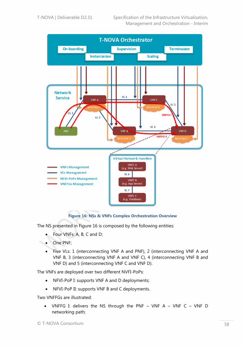
T-NOVA | Deliverable D2.31 Specification of the Infrastructure Virtualisation,
Management and Orchestration - Interim
© T-NOVA Consortium
58
Figure 16: NSs & VNFs Complex Orchestration Overview
The NS presented in Figure 16 is composed by the following entities:
Four VNFs: A, B, C and D;
One PNF;
Five VLs: 1 (interconnecting VNF A and PNF), 2 (interconnecting VNF A and
VNF B, 3 (interconnecting VNF A and VNF C), 4 (interconnecting VNF B and
VNF D) and 5 (interconnecting VNF C and VNF D).
The VNFs are deployed over two different NVFI-PoPs:
NFVI-PoP I: supports VNF A and D deployments;
NFVI-PoP II: supports VNF B and C deployments.
Two VNFFGs are illustrated:
VNFFG I: delivers the NS through the PNF – VNF A – VNF C – VNF D
networking path;
T-NOVA | Deliverable D2.31 Specification of the Infrastructure Virtualisation,
Management and Orchestration - Interim
© T-NOVA Consortium
59
VNFFG II: delivers the NS through the PNF – VNF A – VNF B – VNF D
networking path.
Internally, the VNFs can be composed by one or more software components, also
known as Virtual Network Function Components (VNFCs). Each VNFC is typically
deployed in a single Virtual Machine (VM), although other deployment procedures
can exist. As VNFs, VNFCs can be instantiated in a single NFVI-PoP or distributed
across several NFVI-PoPs. The VNFCs interconnections are made through dedicated
VLs. Figure 16 illustrates the internals of a specific (VNF D). The latter software
components, namely web server (VNFC A), application server (VNFC B) and database
(VNFC C), interconnected through VLs (VL6 and VL7).
On top of all these entities (e.g. NS, VNF, VNFC, VL, NFVI-PoP, etc) stands the
orchestrator, which has responsibility for managing the complexity associated with
the NSs and VNFs lifecycle management (e.g. on-boarding/deployment, instantiation,
supervision, scaling, termination), including the internals of the VNFs (not illustrated
in the figure).
In summary, the T-NOVA Orchestrator platform is focused on addressing two of the
most critical issues in NFV:
1. Automated deployment and configuration of NSs/VNFs;
2. Management and optimisation of networking and IT resources for VNFs
accommodation.
To address the complex management processes related with the NSs and VNFs, the
Orchestrator is split in two main FEs:
1. NFV Orchestrator (NFVO): manages the virtualised NSs lifecycle procedures,
including the networking links that interconnect the VNFs;
2. VNF Manager (VNFM): manages the VNFs lifecycle procedures.
The T-NOVA Orchestrator will also be able to deploy and monitor T-NOVA services
by jointly managing WAN resources and cloud (compute/storage) assets (DCs).
Indeed, the T-NOVA Orchestrator goes beyond traditional cloud management, since
its scope is not restricted to a single DC; it needs to jointly manage WAN and
distributed cloud resources in different interconnected DCs in order to couple the
basic network connectivity service with added-value NFs.
Further details regarding these T-NOVA Orchestrator entities and functionalities are
provided in the following subsections. The VNF related concepts and architectural
components are discussed extensively in Deliverable D2.41 (D2.41) (62).
3.2 Orchestrator requirements
As already outlined in subsection 3.1, the T-NOVA Orchestrator is composed by two
main building blocks: the NFVO and the VNFM.
The NFVO orchestrates the subset of functions that are responsible for the lifecycle
management of Network Services (NSs). In addition, it is also responsible for the
resource orchestration of the NFVI resources across:
T-NOVA | Deliverable D2.31 Specification of the Infrastructure Virtualisation,
Management and Orchestration - Interim
© T-NOVA Consortium
60
a single VIM, corresponding to a single NFVI-PoP, and/or
multiple VIMs, corresponding to multiple NFVI-PoPs, by using a specialized
VIM designated by TNM.
The VNFM is the functional block that is responsible for the lifecycle management of
the VNFs.
The deployment and operational behaviour of the Orchestrator is captured in
deployment templates, where the most important for this subsection are the Network
Service Descriptor (NSD), the Virtual Network Function Descriptor (VNFD). Other
templates are also used, e.g., Virtual Link Descriptor (VLD), and the VNF Forwarding
Graph (VNFFGD), which will be further detailed in subsection 3.3.
This subsection details the Orchestrator requirements that have been identified after
a research study involving several sources, e.g. use cases defined in D2.1 (63), ETSI
ISG NFV requirements (64), ITU-T requirements for NV (10), as well as excerpts of
relevant parts of the ETSI ISG MANO architecture and associated FEs (8).
The list of requirements for each FE may be found in Annex A, where 35 requirements
have been identified for the NFVO and 11 for the VNFM. However, it should be noted
that none of these requirements imposes any specific solution at the implementation
level, which will be performed in WP3/4.
Taking into account that the list of requirements is quite extensive, the entire set of
requirements has been classified and divided into types as indicated in the remaining
part of the current subsection.
3.2.1 NFVO requirements types
Network Services under the responsibility of the NFVO, are composed by VNFs and,
as such, are defined by their functional and behavioural specification. In this context,
the NFVO coordinates the lifecycle of VNFs that jointly realise a NS. This coordination
includes managing the associations between the different VNFs that make-up part of
the NS, and when applicable between VNFs and PNFs, the network topology of the
NS, and the VNFFGs associated with the NS.
The operation of NSs defines the behaviour of the higher Orchestration layer, which
is characterised by performance, dependability, and security specifications. The end-
to-end network service behaviour is the result of combining individual network
function behaviours as well as the behaviours of the composition mechanisms
associated with the underlying network infrastructure layer, i.e. the IVM layer.
In terms of deployment and operational behaviour, the requirements of each NS are
carried in a deployment template, the NSD, and stored during the NS on-boarding
process in the NS catalogue, for future selection once the instantiation of the service
takes place. The NSD fully describes the attributes and requirements necessary to
implement a NS, including the service topology, i.e. constituent VNFs and the
relationships between them, VLs, VNFFGs, as well as NS characteristics, e.g. in terms
of SLAs and any other information necessary for the NS on-boarding and lifecycle
management of its instances.

T-NOVA | Deliverable D2.31 Specification of the Infrastructure Virtualisation,
Management and Orchestration - Interim
© T-NOVA Consortium
61
As the NS is the main responsibility of the NFVO, the NS lifecycle constitutes the
most relevant technical area regarding the NFVO classification in terms of
requirements.
As indicated below, the other requirement types are related with the VNF lifecycle
management with respect to the actions and procedures taken by the NFVO, which
also includes the second FE that constitutes part of the Orchestrator, together with
the NFVO: the VNFM. The actions and procedures associated with the VNFM’s
behaviour, and in particular those related to the VNF lifecycle, will be further
discussed in subsection 3.2.2.
Regarding the remaining requirement types, it should be noted that there is one type
related to the NFVO, which handles the management of the resources located in
the VIM and in the TNM; another one related with the policy management; and
another one, specific to the T-NOVA system, which is concerned with the most
relevant interactions with the Marketplace, the layer immediately above the
Orchestration layer.
Finally, there are still two further types that relate to NS lifecycle operations:
connectivity handling and the monitoring process. A decision was taken to create
separate groups for these two (sub)types in order to emphasize the importance they
play in the overall operation of the Orchestrator.
3.2.1.1 NS Lifecycle
A Service Provider (SP) may choose one or more VNFs to compose a new NS, by
parameterising those VNFs, selecting a SLA, etc. within the context of the T-NOVA
system. The NFVO is then notified of the composition of this new NS, by the
reception of a request that includes a NSD, which is validated in terms of description.
In a similar process, when a Customer subscribes to a NS, the Marketplace notifies
the NFVO, which instantiates the NS according to its NSD description, agreed SLA
and the current status of the overall infrastructure usage metrics. Upon a successful
instantiation, the Orchestrator notifies the Marketplace, thus triggering the
accounting process of the subscribed NS as well as of the customer.
After these steps the NFVO becomes responsible for NS lifecycle management, where
lifecycle management refers to a set of functions required to manage the
instantiation, maintenance and termination of a NS.
3.2.1.2 VNF Lifecycle
The NFVO performs its capabilities by using the VNFM operation in what concerns
the handling of the VNF lifecycle. Although the VNFM is the FE in charge of the
management of the VNF lifecycle, as further described in subsection 3.2.2, some
operations require the intervention of the NFVO.
The requirement type specified in the current subsection refers precisely to those
parts of the VNF lifecycle management that are performed by the NFVO.
In this context, Function Providers (FPs) publicise their VNFs in the Network
Function Store (NF Store). This implies the use of a VNFD describing the

T-NOVA | Deliverable D2.31 Specification of the Infrastructure Virtualisation,
Management and Orchestration - Interim
© T-NOVA Consortium
62
infrastructure (computation, storage, network infrastructure and connection) needed
for the VNF to be instantiated later on by a request sent to the Orchestrator.
After a validation of the VNFD, the NFVO publicises the VNF to the Marketplace as
being ready to be part of a NS. Associated with the VNFD, there may be potentially a
VM image that will make part of the deployment of such VNF.
As the FP provides newer versions this process is repeated. If and when the FP wishes
to withdraw the VNF, the reverse process is executed taking into consideration the
current status of NS exploiting the under deletion VNF.
3.2.1.3 Resource Handling
The NFVO is the Orchestrator FE that performs the resource handling of the subset of
Orchestrator functions that are responsible for global resource management
governance.
In terms of scope, the following domains and associated IT virtualised resources are
managed by the NFVO: Compute, i.e. virtual processing CPUs and virtual memory;
Storage, i.e. virtual storage; and Network, i.e. virtual links intra/interconnecting VNFs
within the Data Centre Network (DCN). In T-NOVA, the NFVO also manages the
resources of the TNM network domain.
The governance described above is performed by managing the between the VNF
instances and the NFVI resources allocated to those VNF instances and by using the
Infra Resources catalogue as well as information received from the VIM and from the
TNM.
According to the characteristics of each service (agreed SLA) and the current usage of
the infrastructure (computation, storage infrastructure and connectivity), there is an
optimal allocation for the required infrastructure.
This optimal infrastructure allocation will be the responsibility of an allocation
algorithm (or a set of algorithms) that will be defined, in WP3.
3.2.1.4 Monitoring Process
One of the key aspects of the T-NOVA project is not only the ability to optimally
allocate infrastructures for a NS, but also to react, in real time, to the current
performance of a subscribed NS, so that the agreed SLA is maintained. To accomplish
these two aspects, it is crucial that a meaningful set of infrastructure (computational,
storage, infrastructure and connectivity) usage metrics be collected.
NS metrics must be defined together with the SLA(s) to be provided with every NS
instantiation.
It is expected that the data to be collected will be significant with a high frequency of
change, so adequate strategies will have to be designed to support collecting large
volumes of data.
As such, during the NS lifecycle, the NFVO may monitor the overall operation of a NS
with information provided by the VIM and/or by the TNM, if such requirements were
captured in the NS deployment template.

T-NOVA | Deliverable D2.31 Specification of the Infrastructure Virtualisation,
Management and Orchestration - Interim
© T-NOVA Consortium
63
Such data may be used to derive usage information for NFVI resources being
consumed by VNF instances or groups of VNF instances. For instance, the process
may involve collecting measurements about the number of NFVI resources consumed
by NFVI interfaces, and then correlating NFVI usage records to VNF instances.
Beyond the infrastructure usage metrics sets of NS usage metrics, need to be defined
upon service composition, in order to allow tracking of the agreed SLA and to
determine if it is being maintained or not.
These metrics are more service oriented than infrastructure oriented, and are built on
top of infrastructure usage metrics. For instance, a metric such as “the current
number of simultaneous sessions” is something that the infrastructure cannot
measure, but the “current maximum network latency” is something available at the
infrastructure level, which might make sense at the service level as well. The choice
between which metrics to track is made by the Marketplace, at service composition
time.
The collection of these measurement metrics may be reported to external entities,
e.g. the Customer, the SP or the FP, via the Marketplace, if such requirements were
captured in the NS deployment template.
In addition, this information may be compared with additional information included
in the on-boarded NS and VNF deployment templates, as well as with policies
applicable to the NS that can be used to trigger automatic operational management
of the NS instance, e.g. automatic scaling of VNF instances that are part of the NS.
3.2.1.5 Connectivity Handling
The NFVO has an abstracted view of the network topology and interfaces to the
underlying VIMs and TNMs in order to handle connectivity services by performing
the management of the NS instances, e.g., create, update, query, delete VNFFGs.
Connectivity management must be handled over the same domains as those
indicated for resource handling.
3.2.1.6 Policy Management
Policies are defined by conditions and corresponding actions/procedures, e.g. a
scaling policy may state execution of specific actions/procedures if the required
conditions occur during runtime. Different actions/procedures defined by the policy
can be mutually exclusive, which implies a process of selection of a particular
action/procedure (or set of actions/procedures) to be executed either automatically
or manually.
In the context of T-NOVA, once declared, a policy may be bound to one or more NS
instances, VNF instances, and NFVI resources. Policy management always implies
some degree of evaluation for the NS instances and VNF instances, e.g., in term of
policies related with affinity/anti-affinity, lifecycle operations, geography, regulatory
rules, NS topology, etc.

T-NOVA | Deliverable D2.31 Specification of the Infrastructure Virtualisation,
Management and Orchestration - Interim
© T-NOVA Consortium
64
In addition, policy management also refers to the management of rules governing
the behaviour of Orchestrator functions, e.g., management of NS or VNF scaling
operations, access control, resource management, fault management, etc.
Associated with the policy management terminology is the concept of policy
enforcement, i.e. polices are defined by certain entities and are then enforced in other
entities, which may in their turn enforce them in additional entities.
In the T-NOVA context, policies may be defined by external entities, e.g. the
Customer, the SP or the FP, and are then enforced into the NFVO, via the
Marketplace. In its turn, the NFVO may enforce them into the VNFM.
Policy enforcement may be static or on-demand.
3.2.1.7 Marketplace-specific interactions
The Marketplace is the T-NOVA layer that interfaces with external entities, e.g.,
Customers, SPs and FPs. In the T-NOVA global architecture, it interacts with the
Orchestration layer through an interface whose requirements are defined in
subsection 3.4.
The deployment and behaviour of the Marketplace imposes requirements that the
Orchestration must fulfil in order to offer those external entities an entire set of
functionalities, which are defined in D2.41 (62).
The request made by the Marketplace for those requirements as well as the
correspondent responses from the Orchestrator are, most of the time, implicit in the
current description of the Orchestrator requirements.
However, for some of those requirements that are based within D2.1 (63), e.g.
publishing the outcome of the NS instantiation, publishing NS metrics, or reporting
usage metrics, it was decided to create a separate group in order to highlight their
processing mechanisms.
For instance, the various kinds of metrics described above may be used by business-
oriented processes residing in the Marketplace, namely to start and stop tracking of
the usage a NS for billing purposes.
3.2.2 VNFM requirements types
The deployment and operational behaviour requirements of each VNF is captured in
a deployment template, the VNFD, and stored during the VNF on-boarding process
in the VNF catalogue as part of a VNF Package, for future use. The deployment
template describes the attributes and requirements necessary to realise such the VNF
and captures, in an abstracted manner, the requirements to manage its lifecycle.
The VNFM performs the lifecycle management of a VNF based on the requirements
included in this template. As such, the VNF lifecycle constitutes the most relevant
type in the VNFM classification of requirements in relation to the procedures taken in
this global process.
As also decided for the NFVO, there is still a further type that constitutes, in fact, an
area of operation that belongs to the VNF lifecycle: the monitoring process. Once

T-NOVA | Deliverable D2.31 Specification of the Infrastructure Virtualisation,
Management and Orchestration - Interim
© T-NOVA Consortium
65
again, the reason behind the creation of a separate group for this (sub)type is related
to emphasising the importance of its rule in the Orchestrator’s operation.
3.2.2.1 VNF Lifecycle
The VNFM is responsible for the VNF lifecycle management, where lifecycle
management refers to a set of functions required to manage the instantiation,
maintenance and termination of a VNF.
3.2.2.2 Monitoring Process
During the lifecycle of a VNF, the VNF Management functions may monitor Key
Parameter Indicator (KPIs) of a VNF, if such KPIs were captured in the deployment
template. The management functions may use this information for scaling operations.
Scaling may include changing the configuration of the virtualised resources (scale
down, e.g., add CPU, or scale up, e.g., remove CPU), adding new virtualised resources
(scale out, e.g., add a new VM), shutting down and removing VM instances (scale in),
or releasing some virtualised resources (scale down).
So, every VNF will usually provide its own usage metrics to the VNFM, which will be,
in general, specific to the function the VNF provides, although they might be based
on the infrastructure on top of which the VNF has been deployed.
The treatment of the information collected during the VNF monitoring process is very
similar to the one described for the NS process and may result in reports being sent
external entities, via the Marketplace, and/or to trigger automatic operational
management of the VNF instance, e.g. automatic scaling.
3.3 Functional Orchestrator Architecture
This subsection describes the Orchestrator reference architecture, including its
functional entities as well as external interfaces.
3.3.1 Reference Architecture
The Orchestrator reference architecture, as well as the interfaces with the external
Functional Entities (FEs) is depicted in Figure 17. In detail, the orchestrator interacts
with the Marketplace, which is the T-NOVA domain responsible for accounting, SLA
management and business functionalities. Besides the Marketplace, the Orchestrator
also interfaces with the IVM, and in particular with the VIM, for managing the data
centre network/IT infrastructure resources, as well as with the TNM for WAN
connectivity management. Finally, the Orchestrator interacts with the VNF itself,
which in the T-NOVA scope is located in the IVM domain, to ensure its lifecycle
management.
Internally, the T-NOVA Orchestrator consists of two main components and a set of
repositories. One of the core elements is the NFVO, acting as the front-end with the
Marketplace and orchestrating all the incoming requests towards the other
components of the architecture. Further details relating to the NFVO and the
associated incoming requests are available in subsection 3.3.2.1. To support the

T-NOVA | Deliverable D2.31 Specification of the Infrastructure Virtualisation,
Management and Orchestration - Interim
© T-NOVA Consortium
66
NFVO operation procedures, a set of repositories is identified in order to store the
description of the available VNFs and NSs (VNF Catalogue and NS Catalogue), the
instantiated VNFs and NSs (NS & VNF Instances), as well as the available resources in
the virtualised infrastructure (Infrastructure Resources Catalogue). Further details
about the orchestrator repositories are provided in subsection 3.3.2.3. Finally, the
NFVO also interacts with the other core element, the VNF Manager (VNFM),
responsible for the VNF-specific lifecycle management procedures, as described in
subsection 3.3.2.2.
Figure 17: T-NOVA Orchestrator Reference Architecture
3.3.2 Functional entities
This subsection describes the functional entities of the Orchestrator architecture.
3.3.2.1 Network Function Virtualisation Orchestrator (NFVO)
The main function of the NFVO is to manage the virtualised NSs lifecycle and its
procedures. Since the NSs are composed by VNFs, (PNFs, VLs and VNFFGs, the NFVO
is able to decompose each NS into these constituents. Nevertheless, although the
NFVO has the knowledge of the VNFs that compose the NS, it delegates their
lifecycle management to another dedicated FE of the Orchestrator domain,
designated by VNFM.
A description of the main deployment templates must be taken into account when
determining the best connectivity paths to deliver a service is provided:
a VNFFGD is a deployment template that describes a topology of the NS or a
portion of the NS, by referencing VNFs and PNFs as well as VLs that used for

T-NOVA | Deliverable D2.31 Specification of the Infrastructure Virtualisation,
Management and Orchestration - Interim
© T-NOVA Consortium
67
interconnection. In addition to the VLs, whose descriptor is described below, a
VNFFG can reference other information elements in the NS such as PNFs and
VNFs. A VNFFG also contains a Network Forwarding Path (NFP), i.e. an
ordered list of Connection Points forming a chain of NFs, along with policies
associated to the list,
a VLD is a deployment template which describes the resource requirements
that are needed for establishing a link between VNFs, PNFs and endpoints of
the NS, which could be met by choosing an option between various links that
are available in the NFVI. However, the NFVO must first consult the VNFFG in
order to determine the appropriate NFVI to be used based on functional (e.g.,
dual separate paths for resilience) and other needs (e.g., geography and
regulatory requirements).
In addition to the orchestration of the virtualised service level operations, which
allows the abstraction of service specificities from the business/operational level – in
this case the T-NOVA Marketplace – the NFVO also manages the virtualised
infrastructure resource level operations as well as the configuration/allocation of
transport connections when two or more distinct DCs are involved. Hence, it
coordinates the resource reservation/allocation/removal to specific NSs and VNFs
according to the availability of the virtualised infrastructures, also known as data
centres.
To address the two main functionalities above mentioned, the NFVO is architecturally
split in two modules, namely the Network Services Orchestrator (NSO) and the
Virtualised Resources Orchestrator (VRO), further described below.
Network Service Orchestrator
The NSO is one of the components of the NFVO with the responsibility for managing
the NS lifecycle and its procedures. More precisely, the following tasks fall under the
responsibility of the NSO:
NSs and VNFs on-boarding: management of Network Services deployment
templates, also known as NS Descriptors and VNF Packages, as well as of the
NSs instances topology (e.g., create, update, query, delete VNF Forwarding
Graphs). On-boarding of a NS includes the registration in the NS catalogue
therefore ensuring that all the templates (NSDs) are stored, see NS on-
boarding procedure detailed in subsection 5.2.1;
NS instantiation: trigger instantiation of NS and VNF instances, according to
triggers and actions captured in the on-boarded NS and VNF deployment
templates. In addition, management of the instantiation of VNFs, in
coordination with VNFMs as well as validation of NFVI resource requests from
VNFMs, as those may impact NSs, e.g. scaling process, see NS instantiation
procedure detailed in subsection 5.2.2;
NS update: support NS configuration changes of various complexity such as
changing inter-VNF connectivity or the constituent VNFs;
NS supervision: monitoring and measurement of the NS performance and
correlation of the acquired metrics for each service instance. Data is obtained
from the IVM layer (performance metrics related with the virtual network links

T-NOVA | Deliverable D2.31 Specification of the Infrastructure Virtualisation,
Management and Orchestration - Interim
© T-NOVA Consortium
68
interconnecting the network functions) and from the VNFM (aggregated
performance metrics related with the VNF, see NS supervision procedure
detailed in subsection 5.2.3;
NS scaling: increase or decrease of the NS capacity according to per-instance
and per-service auto-scaling policies. The NS scaling can imply either
increasing/decreasing of a specific VNF capacity, create/terminate new/old
VNF instances and/or increase/decrease the number of connectivity links
between the network functions;
NS termination: release of a specific NS instance by removing the associated
VNFs and associated connectivity links, as well as the virtualised infrastructure
resources, (see NS termination procedure detailed in subsection 5.2.5).
In addition to these lifecycle related procedures, the NSO also performs policy
management and evaluation for the NS instances and VNF instances, e.g., policies
related with scaling.
Figure 18 provides an illustration about the NSO interactions within the T-NOVA
Orchestrator and with the remaining T-NOVA external entities:
Figure 18: NS Orchestrator (Internal & External) Interactions
From the external perspective, it interacts with the Marketplace for operational and
business management purposes as follows:
Exchange provisioning information (e.g., requests, modifications/updates,
acknowledgements) about the NSs (through the T-Da-Or interface);
Provides the orchestrator with information on each NS instance SLA
agreement. In turn he orchestrator sends SLA-related metrics to the
Marketplace (through the T-Sl-Or interface);
Deliver to the Marketplace usage accounting information with respect to
VNFs and NSs (through the T-Ac-Or interface);

T-NOVA | Deliverable D2.31 Specification of the Infrastructure Virtualisation,
Management and Orchestration - Interim
© T-NOVA Consortium
69
Provides the orchestrator with information about the NSs composition. The
orchestrator delivers to the Marketplace information about the available VNFs
(through the T-Br-Or interface).
Internally, the NSO has the following communication points:
NS Catalogue: collects information about the NSs (NSD), including the set of
constituent VNFs, interconnecting network links (VLD) and network topology
information (VNFFGD);
VNF Catalogue: stores the VNFD during the on-boarding procedures;
NS and VNF Instances: stores information about the NS instances status;
Virtualised Resources Orchestrator (VRO): exchanges management actions
related to virtualised resources and/or connections, either within the data
centre scope (e.g. compute, storage and network) and/or on the transport
network segment;
Virtual Network Function Manager (VNFM): exchange lifecycle
management actions related with the VNFs.
Virtualised Resources Orchestrator
The Virtualised Resources Orchestrator (VRO) is the resource layer management
Functional Entity of the NFVO main block. It is responsible for the following actions:
Coordinate resource reservation/allocation/removal and establish the
placement for each VM that composes the VNF (and the NS);
Interact with the WAN elements for connectivity management actions;
Validate NFVI resource requests from VNFMs, as those may impact the way
the requested resources are allocated within one NFVI-PoP or across multiple
NFVI-PoPs. Whether the resource related requests comes directly from the
VNFM or from the NFVO is implementation dependent;
Manage the relationship between the VNF instances and the NFVI resources
allocated to those VNF instances;
Collect usage information of the NFVI resources;
Collect performance information about the network links interconnecting the
VNFs;
Collect performance about the virtualised infrastructure resources supporting
NSs.
The following virtualised resources are managed by the VRO:
Compute: virtual processing CPUs and virtual memory;
Storage: virtual storage;
Network: virtual links intra/interconnecting VNFs within the DCN.
Figure 19 provides an illustration with further details about the VRO interactions
within the T-NOVA Orchestrator and with the remaining T-NOVA external entities:
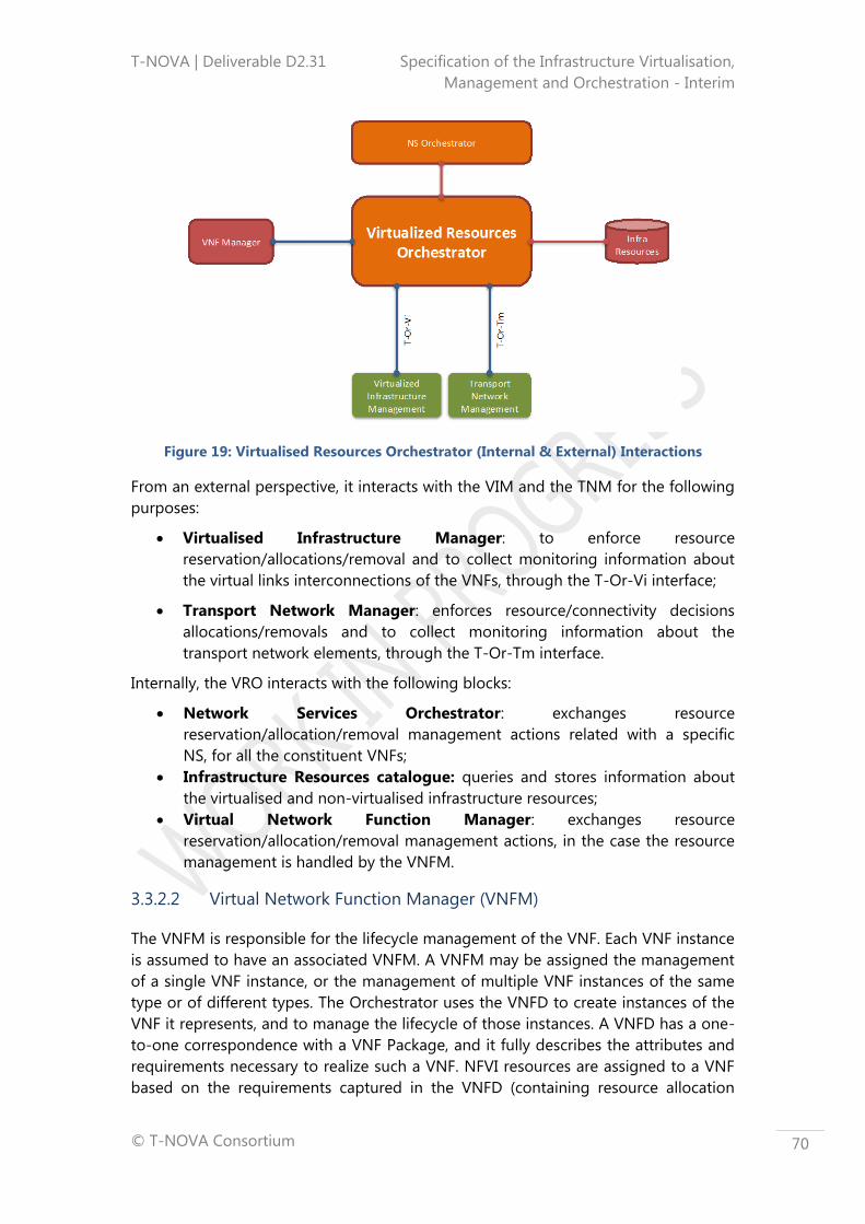
T-NOVA | Deliverable D2.31 Specification of the Infrastructure Virtualisation,
Management and Orchestration - Interim
© T-NOVA Consortium
70
Figure 19: Virtualised Resources Orchestrator (Internal & External) Interactions
From an external perspective, it interacts with the VIM and the TNM for the following
purposes:
Virtualised Infrastructure Manager: to enforce resource
reservation/allocations/removal and to collect monitoring information about
the virtual links interconnections of the VNFs, through the T-Or-Vi interface;
Transport Network Manager: enforces resource/connectivity decisions
allocations/removals and to collect monitoring information about the
transport network elements, through the T-Or-Tm interface.
Internally, the VRO interacts with the following blocks:
Network Services Orchestrator: exchanges resource
reservation/allocation/removal management actions related with a specific
NS, for all the constituent VNFs;
Infrastructure Resources catalogue: queries and stores information about
the virtualised and non-virtualised infrastructure resources;
Virtual Network Function Manager: exchanges resource
reservation/allocation/removal management actions, in the case the resource
management is handled by the VNFM.
3.3.2.2 Virtual Network Function Manager (VNFM)
The VNFM is responsible for the lifecycle management of the VNF. Each VNF instance
is assumed to have an associated VNFM. A VNFM may be assigned the management
of a single VNF instance, or the management of multiple VNF instances of the same
type or of different types. The Orchestrator uses the VNFD to create instances of the
VNF it represents, and to manage the lifecycle of those instances. A VNFD has a one-
to-one correspondence with a VNF Package, and it fully describes the attributes and
requirements necessary to realize such a VNF. NFVI resources are assigned to a VNF
based on the requirements captured in the VNFD (containing resource allocation
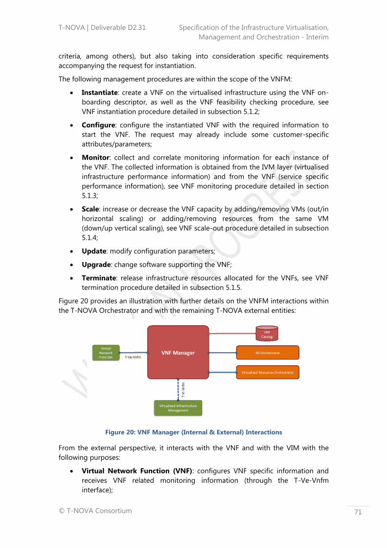
T-NOVA | Deliverable D2.31 Specification of the Infrastructure Virtualisation,
Management and Orchestration - Interim
© T-NOVA Consortium
71
criteria, among others), but also taking into consideration specific requirements
accompanying the request for instantiation.
The following management procedures are within the scope of the VNFM:
Instantiate: create a VNF on the virtualised infrastructure using the VNF on-
boarding descriptor, as well as the VNF feasibility checking procedure, see
VNF instantiation procedure detailed in subsection 5.1.2;
Configure: configure the instantiated VNF with the required information to
start the VNF. The request may already include some customer-specific
attributes/parameters;
Monitor: collect and correlate monitoring information for each instance of
the VNF. The collected information is obtained from the IVM layer (virtualised
infrastructure performance information) and from the VNF (service specific
performance information), see VNF monitoring procedure detailed in section
5.1.3;
Scale: increase or decrease the VNF capacity by adding/removing VMs (out/in
horizontal scaling) or adding/removing resources from the same VM
(down/up vertical scaling), see VNF scale-out procedure detailed in subsection
5.1.4;
Update: modify configuration parameters;
Upgrade: change software supporting the VNF;
Terminate: release infrastructure resources allocated for the VNFs, see VNF
termination procedure detailed in subsection 5.1.5.
Figure 20 provides an illustration with further details on the VNFM interactions within
the T-NOVA Orchestrator and with the remaining T-NOVA external entities:
Figure 20: VNF Manager (Internal & External) Interactions
From the external perspective, it interacts with the VNF and with the VIM with the
following purposes:
Virtual Network Function (VNF): configures VNF specific information and
receives VNF related monitoring information (through the T-Ve-Vnfm
interface);
T-NOVA | Deliverable D2.31 Specification of the Infrastructure Virtualisation,
Management and Orchestration - Interim
© T-NOVA Consortium
72
Virtual Infrastructure Management (VIM): collects monitoring information
about the virtualised infrastructure resources allocated to the VNF (through
the T-Vi-Vnfm interface).
Internally, the VNFM interacts with the following components:
Network Services Orchestrator (NSO): receive VNF instantiation requests for
a specific NS and provide VNF monitoring information;
VNF Catalogue: collects information about the VNFs internal composition
(VNFD), including the VNF Components (VNFCs), software images (VMs) and
management scripts;
Virtualised Resources Orchestrator (VRO): exchanges resource
reservation/allocation/removal management actions, in cases where the
management is handled by the VNFM.
3.3.2.3 Repositories and Catalogues
To support the T-NOVA Orchestrator lifecycle management operations, the following
catalogues are defined:
NSs Catalogue (NS Catalogue);
VNFs Catalogue (VNF Catalogue);
NSs and VNFs Instances Repository;
Infrastructure Resources Repository.
NS Catalogue
Represents the repository of all the on-boarded NSs in order to support the NS
lifecycle management:
NS Descriptor (NSD): contains the service description template, including
SLAs, deployment flavours, references to the virtual links (VLDs) and the
constituent VNFs (VNFFG);
Virtual Link Descriptor (VLD): contains the description of the virtual network
links that compose the service (interconnecting the VNFs);
VNF Forwarding Graph Descriptor (VNFFGD): contains the NS constituent
VNFs, as well as their deployment in terms of network connectivity.
VNF Catalogue
Represents the repository of all the on-boarded VNFs in order to support its lifecycle
management:
VNF Descriptor (VNFD): contains the VNF description template, including its
internal decomposition in VNFCs, deployment flavours and references to the
VLDs;
Software images of the VMs located in the IVM layer.

T-NOVA | Deliverable D2.31 Specification of the Infrastructure Virtualisation,
Management and Orchestration - Interim
© T-NOVA Consortium
73
NS & VNF Instances
Represents the repository of all the instantiated NSs and VNFs, which can be
created/updated/released during the lifecycle management operations.
Infrastructure Resources
Represents the repository of available, reserved and allocated NFVI-PoP resources,
also including the ones related to the WAN segment.
3.3.3 External Interfaces
In this section the external interfaces of the Orchestrator are described. However it is
important within the perspective of the T-NOVA architecture to understand the
context in which the term interface is used as is its relationship to reference points a
common architectural locus used within the networking domain
In network terms a reference point is an abstract point in a model of network or
protocol. This reference point essentially serves to partition functions or
configurations and so assists in the description of a network model as well as serving
as a point of interoperability between different parts of the network (65). In a
networking context, an interface may or may not be associated with any given
reference point. An interface typically represents a protocol level connection which
may or may not be mapped to a reference point.
This strict delimitation between the definition of reference points and interfaces in
the context of NFV and SDN given the hybridisation of networking and IT
technologies can be challenging, i.e. in the network domain, this framework is strictly
defined, and it is therefore normal practice to retain the use of the term reference
point, while in the IT domain, there is a more flexible demarcation between
technologies leading to a degree of hybridisation. As a consequence in the IT domain
the term interface is used in a more flexible manner to encompass reference points
also.
While strictly speaking the separation of the terms should be technically maintained
the approach adopted in this deliverable is to utilise a broader and more flexible
definition of interfaces and reference points given the expected one-to-one mapping
of reference points and interfaces in the context of the proposed T-NOVA
architecture. Additionally interfaces in the T-NOVA system may not necessarily be
tied specifically to a protocol but rather act as point of information exchange through
APIs. Hence within the context of this deliverable interfaces are envisioned to
encompass both the architectural characteristics of interfaces and references points
given fusion of the IT and networking domains.
Having clarified the use of the term, the description of the Orchestrator’s external
interfaces will start to be provided by means of a very short reference on security,
which is a common area that affects all the interfaces. It will be followed by an
introduction to the interface requirements that are presented in Annex A.2 in a
tabular format.

T-NOVA | Deliverable D2.31 Specification of the Infrastructure Virtualisation,
Management and Orchestration - Interim
© T-NOVA Consortium
74
Regarding the common issue, and considering the most generic scenarios in which
the roles described in D2.1 (63) are played by distinct entities all the external
interfaces being described in this section must support at least a minimum degree of
security. The decision on the exact degree of security for each implemented interface
will be taken later in the project’s timeline.
3.3.3.1 Interface between the Orchestrator and the Network Function Store
The interface between the Orchestrator and the Network Function Store (NF Store)
serves two purposes:
For the NF Store, to notify the Orchestrator about new, updated and
withdrawn VNFs;
For the Orchestrator, to retrieve from the NF Store and store in the VNF
Catalogue the VNFD and VMs images that need to be instantiated to support
that VNF.
This “two-phase” interaction between the Orchestrator and the NF Store, instead of
just one in which the NF Store could pass the Orchestrator the VNF Descriptor and
VM images, allows for the optimisation of resources on both sides of the interface.
On the NF Store side this is just a notification to the Orchestrator, and on the
Orchestrator’s side, the download of the VM images is only carried out when the VNF
is instantiated preventing unnecessary use of resources. Uploading of the VNFD to
the VNF catalogue is executed at the start of the VNF on-boarding process.
3.3.3.2 Interface between the Orchestrator and the Marketplace
The interface between the Orchestrator and the Marketplace serves the following
purposes:
Provide available VNFs: involves SP browsing and selection of VNFs, as well
as composition of market services by the Marketplace, followed by a request
to the Orchestrator;
Publish a new network service: related to the request for the storage of
information related to a new service by the Marketplace, included in the
provision of the NSD, see subsection 3.2. This process is also called NS on-
boarding by the Orchestrator FEs;
Request for a Network Service: after a Customer’s or a SP subscription of a
service, a subsequent request from the Marketplace is generated, which
includes in the NSD all the VNFs the NS to be deployed needs, as well as all
the VMs those VNFs need in the VNFD, the available infrastructure and its
current usage;
Change configuration of a deployed network service upon a request from
the Marketplace;
Provide network service state transitions: notification provided by the
Orchestrator to the Marketplace;
T-NOVA | Deliverable D2.31 Specification of the Infrastructure Virtualisation,
Management and Orchestration - Interim
© T-NOVA Consortium
75
Provide network service monitoring data: notification provided by the
Orchestrator to the Marketplace;
Terminate a provisioned network service: upon a request from the
Marketplace when there is an explicit solicitation.
3.3.3.3 Interface between the Orchestrator and the VIM
The interface between the Orchestrator and the VIM serves the following purposes:
Allocate/release/update resources: upon a request from the Orchestrator to
(re)instantiate, update the configuration of, or release a resource (VM or
connection within the same DC);
Reserve/release resources: upon an expected future need from the
Orchestrator to instantiate or release a reserved resource (VM or connection
in the same DC). This requirement makes sense in scenarios where allocating
resources from scratch is complex or too time consuming for the purpose in
mind. Reserved resources may have lower prices than effective allocated ones
and become faster to allocate when time comes;
Add/update/delete SW image: whenever a new, update or removal of a VM
image is needed in the process of allocating, updating or removing a new
VNF/VNFC instance;
Retrieve infrastructure usage data to NSO: information provided by the
VIM to the Orchestrator, NSO FE, so that optimal allocation of NS instances is
possible and an adequate level of metrics can be reported to the Marketplace,
if allowed by information included in the NSD;
Retrieve infrastructure usage data to VNFM: information provided by the
VIM to the Orchestrator, VNFM FE, so that optimal allocation of VNF instances
is possible and an adequate level of metrics can be reported, via NSO, to the
Marketplace, if allowed by information included in the VNFD;
Retrieve infrastructure resources metadata to VRO: information provided
by the VIM to the Orchestrator, VRO FE, so that optimal allocation of NS
instances is possible, according to the characteristics of the supporting
infrastructure (e.g., the availability of specialized components, such as
Graphical Processing Units (GPUs) or Digital Signal Processors (DSPs), as well
as the maximum number of vCPUs or Giga-bytes of RAM, which will influence
the allocating algorithm for determining the most appropriate resources);
Manage VM’s state: information provided by the VIM to the Orchestrator,
VNFM FE, so that atomic operations, such as redeployment/withdrawal of an
entire VNF, on the allocated VMs are feasible (depending on the
implementation approach, these operations can also be done by the IVM
layer).

T-NOVA | Deliverable D2.31 Specification of the Infrastructure Virtualisation,
Management and Orchestration - Interim
© T-NOVA Consortium
76
3.3.3.4 Interface between the Orchestrator and the Transport Network
Management
The interface between the Orchestrator and the Transport Network Management
serves the following purposes:
Allocate/release/update transport connection: upon a request from the
Orchestrator to (re)instantiate, update the configuration of or release a
transport connection (between two distinct DCs);
Reserve/release transport connection: upon an expected future need from
the Orchestrator to instantiate or release a transport connection (between two
distinct DCs). This requirement makes sense in scenarios where allocating
connections from scratch is complex or too time consuming. Reserved
connections may have lower prices than effective allocated ones and become
faster to allocate when time comes;
Retrieve transport connection usage data to NSO: information provided by
the TNM to the Orchestrator, NSO FE, so that optimal allocation of transport
connections between two or more distinct DCs is possible and an adequate
level of metrics can be reported, together with VNF an NS level metrics, to the
Marketplace;
Retrieve transport connection metadata: information provided by the TNM
to the Orchestrator, VRO FE, such that the optimal allocation of transport
connections between two or more distinct DCs is made possible, according to
the characteristics of the supporting infrastructure e.g., maximum number of
vLinks allowed, maximum bandwidth, etc.;
Manage transport connection state: information provided by the TNM to
the Orchestrator, NSO FE, so that atomic operations, such as
redeployment/withdrawal of an entire VNF within different DCs are feasible
(depending on the implementation approach, these operations can also be
executed by the IVM layer).
3.3.3.5 Interface between the Orchestrator and the VNF
The interface between the Orchestrator and the VNF serves the following purposes:
Instantiate/terminate VNF: sent by the VNFM as a request, whenever an
instance of a NS of which the VNF is a component is to be launched or
removed. Removal of a VNF instance can only be done if there is no NS
instance using that VNF.
Retrieve VNF instance run-time information: sent by the VNFM, so that
VNF SLA metrics can be checked and the SLA can be fulfilled;
Configure a VNF: sent by the VNFM, so that open configuration parameters
can be fulfilled later or changed after the VNF instance is already running;
Manage VNF state: sent by the VNFM, so that the Orchestrator is able to
start, stop, suspend already running VNF instances;

T-NOVA | Deliverable D2.31 Specification of the Infrastructure Virtualisation,
Management and Orchestration - Interim
© T-NOVA Consortium
77
Scale VNF: sent by the VNFM, so that VNF scaling is feasible. All the VNF
scaling information is available in the VNFD. Virtualised resources are
available through the VRO.

T-NOVA | Deliverable D2.31 Specification of the Infrastructure Virtualisation,
Management and Orchestration - Interim
© T-NOVA Consortium
78
4. THE T-NOVA IVM LAYER
4.1 INTRODUCTION
T-NOVA’s Infrastructure Virtualisation and Management (IVM) layer provides the
requisite hosting and execution environment for VNFs. The IVM incorporates a
number of key concepts that influence the associated requirements and architecture
for the layer. Firstly the IVM supports separation between control and data planes
and network programmability. The T-NOVA architecture leverages SDN for designing,
dimensioning and optimising control- and data-plane operations separately, allowing
capabilities from the underlying hardware to be exposed independently. Secondly the
IVM is based around the use of clusters of commodity computing nodes in cloud
computing configurations to support instantiation of software components in the
form of VMs for NFV support, offering resource isolation, optimisation and elasticity.
This configuration should support automated deployment of VNFs from the T-NOVA
marketplace and dynamically expansion/resizing of VMs as required by SLAs. Building
on physical IT and network resource domains the IVM provides full abstraction of
these resources to VNFs. Finally the IVM must expose the necessary external and
internal interfaces to support appropriate integration. The external interfaces provide
connectivity with the T-NOVA Orchestration layer in order to execute requests from
the Orchestrator and secondly to provide information on the infrastructure and VNF
being hosted in order for the Orchestrator to make effective management decisions.
The internal interfaces provide connectivity between the internal domains of the IVM
to ensure the requests for the creation, deployment, management and termination of
VNF services and their host VMs can be executed appropriately among the
constituent infrastructure and control components.
For an architectural perspective the IVM is comprised of NFVI, VIM and TNM
capabilities. The NFVI in turn is composed of Compute, Hypervisor and Network
Domains. The VIM is comprised of compute, hypervisor and network control and
management capabilities, while the TNM works as a single FE. All the various domains
within the IVM implement northbound and southbound interfaces to provide
management, control and monitoring of the composite infrastructure, both physical
and virtualised. Secondly these interfaces provide the key integration capabilities
within the overall T-NOVA system architecture.
The following sections describe the key objectives and characteristics of the IVM and
its constituent components, along with their requirements. These requirements where
then utilised together with T-NOVA D2.1 (63) and D2.21 (4) to define the architecture
of IVM in a manner that addressed these requirements and the overall goals of T-
NOVA. The architecture for T-NOVA is presented as an overall integrated architecture
together with detailed descriptions of the architecture FEs and interfaces of the
constituent domains.

T-NOVA | Deliverable D2.31 Specification of the Infrastructure Virtualisation,
Management and Orchestration - Interim
© T-NOVA Consortium
79
4.2 OBJECTIVES AND CHARACTERISTICS OF THE T-NOVA
IVM LAYER
The T-NOVA IVM is considered to comprise of a mixture of physical and virtual nodes
and will be used to develop, implement and showcase T-NOVA’s services. The IVM
will be fully integrated with the T-NOVA Orchestrator to ensure that requirements for
the deployment and lifecycle management of T-NOVA VNF services can be carried
out in an appropriate and effective manner. The IVM should be sufficiently flexible to
support a variety of use cases beyond those explicitly identified in T-NOVA (see D2.1
(63)). As mentioned previously, infrastructure virtualisation plays a key role in
achieving this vision in T-NOVA. Virtualisation and management of the virtualised
resources extends beyond the compute and storage to include network infrastructure
in order to fully exploit the capabilities of the T-NOVA architecture. Virtualisation of
the DC network infrastructure allows decoupling of the control functions from the
physical devices they control. In this regard the T-NOVA will implement an SDN
control plane for designing, dimensioning and optimising the control- and data-
plane operations separately, allowing capabilities from the underlying hardware to be
exposed independently.
In summary the key objectives for the T-NOVA IVM are as follows:
Support separation of control and data plane and network programmability at
least at critical locations within the network such as the network
access/borders,
Utilisation of commodity computing nodes in cloud configurations to support
the instantiation of software components in the form of VMs for NFV support,
offering resource isolation, optimisation and elasticity,
Use of L2 Ethernet switched networks (subnets) to provide physical network
connectivity between servers,
Each server supports virtualisation and hosts a number of VMs (virtual
appliances) belonging to their respective vNets. Virtual switch instances or
real physical SDN-capable switches handle network connectivity among the
VMs either on the same server or among the servers co-located in the same
DC,
Interconnection of L2 subnets inside and outside DC’s boundaries via a L3
network (IP routers). This inter data centre connectivity is provisioned through
appropriate WAN ingress and egress points.
Virtualisation of compute and network resources allows the T-NOVA system
to dynamically expand/resize VMs. This accommodates for dynamic scaling of
sudden spikes in the workload; the instantiation of network elements as VMs
into clusters of nodes facilitates horizontal scaling (hosting of many VM
instances into the same cluster) and vertical scaling (automatic re-sizing of
VM instances according to function requirements and traffic load) (see T-
NOVA requirements/use cases – D2.1 (63)).

T-NOVA | Deliverable D2.31 Specification of the Infrastructure Virtualisation,
Management and Orchestration - Interim
© T-NOVA Consortium
80
4.3 T-NOVA IVM LAYER REQUIREMENTS
The requirements capture process focused on identifying the desired behaviours of
the IVM. The requirements identified focus on the entities within the IVM, the
functions that are performed to change states or object characteristics, monitoring of
state and the key interactions with the T-NOVA Orchestration layer. None of these
requirements specifies how the system will be implemented. Implementation details
are left to the appropriate tasks in WP3/4 as the implementation-specific descriptions
are not considered to be requirements. The goal of the requirements was to develop
an understanding of what the IVM needs, how it interacts with Orchestration layer, its
relationship to the overall T-NOVA architecture described in D2.21 (4). Additionally
the use cases included in D2.1 (63) were also considered and cross-referenced with
IVM requirements where appropriate.
The initial phase of eliciting requirements included:
Reviewing available documentation including early and final drafts of (63) and
(66),
Reviewing the high level T-NOVA architecture that was developed by Task 2.2
to gather information on how the users and service providers will perform
their tasks such as VNF deployment, scale out etc., and to better understand
the key characteristics of the T-NOVA system that will be required to realise
user goals including those at a system level.
The adopted approach was generally in-line with the Institute of Electrical and
Electronics Engineer (IEEE) guidelines for requirements specification. A similar process
was used in Tasks 2.1 and 2.2. Requirements were primarily anchored to the existing
T-NOVA use cases and the interactions with Orchestrator both in terms of the actions
and requests that Orchestrator would expect the IVM to execute. Additionally the
data/information that is required by the Orchestrator to successful deploy and
manage VNF services were considered. Identified requirements were primarily
functional in nature since they were related to the behaviour that the IVM is expected
to exhibit under specific conditions. In addition ETSI’s NFV Virtualisation Framework
requirements were also considered, in order to ensure approach scope and coverage
for the requirements that have been specified. The following are the key categories of
requirements that were considered:
Portability,
Performance,
Elasticity,
Resiliency,
Security,
Service Continuity,
Service Assurance,
Operations and Management,
Energy Efficiency.
Using a system engineering approach the high level architecture for the IVM was
previously described in (4). Each component of the overall system was specified in

T-NOVA | Deliverable D2.31 Specification of the Infrastructure Virtualisation,
Management and Orchestration - Interim
© T-NOVA Consortium
81
terms of high-level functional block and the interactions between the functional
blocks are specified as interfaces. This approach identified the following functional
blocks:
Virtualised Infrastructure Management (VIM),
Transport Network Management (TNM),
Infrastructure Elements, consisting of Computing, Hypervisor and Networking.
The requirements presented in the following section are related to these functional
blocks and were developed using the previously described methodology. These
requirements were used as a foundational input into the development of the overall
IVM architecture and its constituent functional blocks, which is presented in
subsection 4.4.
A detailed specification of the requirements for each module within the scope of the
T-NOVA IVM architecture can be found in Annex B. A total of 70 requirements were
identified and documented relating to the VIM, NFVI (compute, hypervisor, DC
network) and TNM. It should be noted that requirements that relate to basic
expected behaviours of the various domains components have been excluded in
order to focus on requirements that are specifically needed by the T-NOVA system.
Analysis of these requirements has identified the following conclusions for each
architectural module.
4.3.1 Virtual Infrastructure Manager
The VIM is required to manage both the IT (compute and hypervisor domains) and
network resources by controlling the abstractions provided by the Hypervisor and
Infrastructure network domains. It also implements mechanisms to efficiently utilise
the available hardware resources in order to meet the SLAs of the VNFs and NSs. The
VIM is also required to play in a key role in the VNF lifecycle management.
Additionally, the VIM is required to collect infrastructure utilisation/performance data
and to make this data available to the Orchestrator in order to generate
usage/performance statistics. The specifics of how the metrics are provisioned and
processed at both the VIM and Orchestrator layers can vary and will typically be
implementation specific. The details of the T-NOVA implementation will be
determined in WP3/4. To accomplish these goals the VIM needs the following
capabilities:
The Network Control capability in the VIM requires SDN features to manage
the infrastructure network domain within an NFVI-PoP;
Hardware abstraction in the Compute domain for efficient management of
resources; However, the abstraction process should ensure that platform
specific information relevant to the performance of VNFs is available for
resource mapping decisions;
Virtual resource management in the Hypervisor domain to provide
appropriate control and management of VMs;
Strong integration between these three sub-domains through appropriate
interfaces;
T-NOVA | Deliverable D2.31 Specification of the Infrastructure Virtualisation,
Management and Orchestration - Interim
© T-NOVA Consortium
82
Integration with the Orchestrator via well-defined interfaces to provide
infrastructure related data to the Orchestrator and to receive management
and control requests from Orchestrator for execution by the VIM.
4.3.2 Transport Network Management
The Transport Network Management is expected to provide the connectivity to NSs
allocated in more than one NFVI-PoP. Connectivity should take form of VLAN to
WAN connections through ingress and egress points at each NFVI-PoP involved in
the NS service. This connectivity has to be provided in a configurable manner (i.e.
supports a high level of customisation). Moreover, to setup this connectivity,
cooperation between the TNM and the NFVI Network domain is needed in order to
allocate the traffic over the inter-DC and intra-DC networks in an appropriate
manner.
4.3.3 NFVI Compute
The NFVI Compute domain should be able to provide an appropriated performance
level for the VNFs that are been deployed in terms of performance and utilisation of
the infrastructure resources. Moreover, the compute nodes and the hypervisor should
work in an integrated and performant manner. The compute domain should collect
metrics on the performance of the physical resources and make them available over a
suitable interface to the Orchestrator. Finally, the T-NOVA Compute domain should
have the capability, if required by a network service, to support heterogeneous
compute resources, such as Graphical Processing Unit (GPUs), Field Programmable
Gate Array (FPGAs), Multi-Integrated Cores (MICs) etc.
4.3.4 NFVI Hypervisor
The NFVI Hypervisor domain should be able to implement hardware resource
abstraction, virtual resource lifecycle management mechanisms which are
coordinated by the Orchestrator via the VIM, and to provide to the VIM monitoring
information while having minimal impact on the VNF workload performance.
Additional details on the collection, processing and utilisation of metrics in the T-
NOVA system can be found in subsection 5.3.
4.3.5 NFVI DC Network
The NFVI DC Network domain should implement an SDN approach to provide
network virtualisation capabilities inside a NFVI-PoP (creation of multiple distinct
domains over one single physical network using VLANs), network programmability
through the separation between Control Plane (CP) and Data Plane (DP), and, at the
same time, it should support transport tunnelling protocols of L2 packets over L3
networks, to assist the TNM in setting up the communication between different NFVI-
PoPs. It should also be able to gather performance data and send them to the VIM
Network Control module.
T-NOVA | Deliverable D2.31 Specification of the Infrastructure Virtualisation,
Management and Orchestration - Interim
© T-NOVA Consortium
83
4.4 T-NOVA IVM Architecture
As mentioned above, the T-NOVA IVM layer comprises of three key architectural
components namely the NFVI, the VIM and the TNM.
The high-level architecture, which has previously been described in D2.21 (4), was
designed to align with the ETSI MANO architecture featuring corresponding
components to the NFVI and the VIM. However, the addition of the TNM is a T-NOVA
specific feature.
The approach adopted in the design and elucidation of the IVM focused on the
functional characteristics of the overall IVM architecture and its sub domains. Careful
consideration was given to decoupling the functional characteristics from
implementation-oriented designs. This allowed us to focus on what the IVM needs to
do rather to avoid the inclusion of implementation-orientated functionality. A good
example of where this approach generated challenges was with the VIM architecture
where there was a tendency to gravitate towards technology solutions as a means to
easily encapsulate functional needs. However careful consideration of the key inputs
was important in fully decoupling functional needs from implementation details to
ensure that T-NOVA IVM architecture remains technology-agnostic but at same time
provides appropriate guidance and structure to the activities in WP3/4.
The key inputs that were considered during the architecture design process are the
following:
D2.1 (Use case and requirements) (63),
D2.21 (subsection 3.3.3) (4),
DGS NFV-INF 001 v0.3.8 - Infrastructure Overview (67),
DGS NFV-INF 003 v0.3.1 - Architecture of the Compute Domain (68),
DGS NFV-INF 004 v0.3.1 - Architecture of the Hypervisor domain (69),
DGS NFV-INF 005 v0.3.1 - Infrastructure network domain (5),
DGS NFV-INF 007 v0.3.1 - Interfaces and Abstractions (70),
DGS NFV-MAN 001 v0.6.3 - Management and orchestration (8),
DGS NFV-REL 001 v0.1.3 - Resiliency Requirements (71),
DGS NFV-SWA 01 v0.2.0 - VNF Architecture (7).
The IVM architecture has been defined in accordance to a systems design process
which was used to identify the components, modules, interfaces, and data necessary
for the IVM in order to satisfy the requirements outlined in the previous subsection
and those described in D2.1 (63) and D2.21 (4). Figure 21 shows the overall
architecture of the VIM, as discussed so far.
4.4.1 External Interfaces
The key external interfaces for the IVM are outlined in Table 6. These interfaces
primarily deal with the connection between the IVM and the T-NOVA Orchestrator;

T-NOVA | Deliverable D2.31 Specification of the Infrastructure Virtualisation,
Management and Orchestration - Interim
© T-NOVA Consortium
84
however there is also an external interface between the TNM and the transport
network.
The interfaces between the Orchestrator and VIM support a number of key functions
within T-NOVA. The functions supported by the interfaces can be categorised as
either management or control. As shown in the IVM architecture in Figure 21, two
specific interfaces have been identified, mapping to the interfaces identified in the
ETSI MANO architecture.
Figure 21: T-NOVA infrastructure virtualisation and management (IVM) high level
architecture
The first interface is the VNFM – VIM Interface (T-Vi-Vnfm) and is responsible for the
exchange of infrastructure monitoring information either through explicit request by
the Orchestrator or through periodic reporting initiated by the VIM. The types of data
exchanged over this interface include detail information on the status, performance
and utilisation of infrastructural resources (such CPU, storage, memory, etc.). Data will
also encompass networking information relating to a specific VNF such as NIC level
network traffic from the hosting VM or inter VM network traffic, if a VNF is deployed
across more than one VM.
Finally VNF performance data will also be exchanged over this interface. Collectively
the data will be used by the VNF Manager within the T-NOVA Orchestrator to track
VNF service performance by comparison with specific KPIs in order to ensure SLA
compliance.
The second interface identified is the NFV Orchestrator – VIM interface (T-Or-Vi). This
interface is responsible for handling requests from the NFV Orchestrator with respect

T-NOVA | Deliverable D2.31 Specification of the Infrastructure Virtualisation,
Management and Orchestration - Interim
© T-NOVA Consortium
85
to the full lifecycle of a NS. Typical examples of requests sent over this interface
would include, for example, parts of the on-boarding, scaling and termination
procedures of a NS. This interface will be used by the NFV Orchestrator to send
resource related commands/information to the VIM such as resource
reservation/allocation or configuration definitions of VMs (e.g. HEAT templates in an
OpenStack Cloud environment or network requirements such as the specification of
the interconnections between VNF instances, i.e. network topology). Specific types of
monitoring information will also be exchanged over this interface such as data
related to the network connections between NS instances either within a data centre
or within intra data centre connections that are physically dispersed. This interface is
also used by the VIM to report back to the NFV Orchestrator the outcome of all
received requests.
The Transport Network Manager provides management capabilities of network
connectivity between NFVI-PoPs. The NFV Orchestrator – Transport Network
Interface (T-Or-TN) interface support requests from the NFV Orchestrator to provide
connectivity to either SDN Controlled or non SDN control transport networks (such as
IP or MPLS based networks) typically for inter DCs (MAN or WAN). These networks
are non-virtualised in nature.
The TNM Interface – External networks (T-Ex-TN) is the explicit network connection
to the transport network. The implementation of this interface will vary based on the
protocol the network is using. More than one interface may also be implemented if
connectivity to different types of transport networks is required.
Table 6: External Interfaces of the T-NOVA IVM
T-Nova
Name
T-NOVA
Reference
ETSI ISG NFV
Framework
Reference Point
Reference
Point Type
Description and
Comment
Virtual
Network
Function
Management–
VIM Interface
T-Vi-Vnfm Vi-Vnfm Management
Interface
This interface is
responsible for the
exchange of
infrastructure
monitoring
information either
through explicit
request by the
Orchestrator or
through periodic
reporting initiated by
the VIM. The types of
data exchanged over
this interface include
status, performance
and utilisation of
infrastructural
resources

T-NOVA | Deliverable D2.31 Specification of the Infrastructure Virtualisation,
Management and Orchestration - Interim
© T-NOVA Consortium
86
NFV
Orchestrator–
VIM Interface
T-Or-Vi Or-Vi Orchestration
Interface
This interface allows
the NFV Orchestrator
to request/reserve
and configure
resources to the VIM
and for the VIM to
report the
characteristics,
availability, and
status of
infrastructure
resources.
NFV
Orchestrator–
Transport
Network
Interface
T-Or-TN - Orchestration
Interface
This interfaces the
TNM with the NFV
Orchestrator and is
used to manage the
set-up, tear down
and monitoring of
connections in
transport networks.
Transport
Network
Interface–
External
networks
T-Ex-TN Ex-Nf Traffic
Interface
This interfaces the
TNM with existing
transport networks
(SDN-enabled or
non-SDN-enabled)
and are used to
implement requests
received from the
Orchestrator via the
Or-TN interface.
4.4.2 Internal IVM Interfaces
The key internal interfaces of the IVM as outlined in Table 7. The interface for NFVI
management including its functional entities is provisioned via the T-Nf-Vi interface.
It is this interface, which will be utilised to establish trust and compliance of the
underlying infrastructure specifically the Hypervisor domain via the T-Nf-Vi/H
implementation of the interface, the compute domain via the T-Nf-Vi/C interface and
the network domain via the T-Nf-Vi/N interface. A full description of these interfaces
is presented in Table 7. A possible deployment configuration for the VIM could be
provided running it within a hosted VM (it can be virtualised). For this specific
configuration, the T-Nf-Vi management interface might be abstracted as a SWA-5
interface (see Figure 3). However, even if this configuration is possible, it is not
desirable, due to security concerns and FE responsibilities. There are also reliability
concerns regarding virtualising the VIM on the same infrastructure that it is
managing. In a scenario where the hypervisor domain of the NFVI requires a restart,
the VIM will lose its ability to operate and continue to manage the NFVI therefore the
VIM should run on separated hardware platforms.

T-NOVA | Deliverable D2.31 Specification of the Infrastructure Virtualisation,
Management and Orchestration - Interim
© T-NOVA Consortium
87
One of the interfaces that are internal to the NFVI is the SWA-5 interface2, which is
used for resources, such as a virtual NIC, a virtual disk drive, virtual CPU, etc.
Examining Figure 21, this interface involves both the T-Vn-Nf/VN and T-Vn-Nf/VM. It
is not intended for use as a management interface; hence a VNF should not use
SWA-5 to manage the NFVI. This interface is primarily intended to logically fence off
responsibilities, but is also intended for security considerations. In fact, reasonable
steps must be taken to prevent unauthorised access, from within a VM, from
attacking the underlying infrastructure and possibly shutting down the entire domain,
including all other adjacent VMs.
Table 7: Internal interfaces of the IVM
T-Nova
Name
T-NOVA
Referenc
e
ETSI NFV
Framework
Reference
Point
INF
Reference
Point
Reference
Point Type
Description and
Comment
VIM-
Network
Interface
T-Nf-Vi/N
Nf-Vi
[Nf-Vi]/N
Management,
Orchestration
and
Monitoring
Interface
This interface is
used for the
management of
Infrastructure
Network domain
resources.
VIM-
Hypervisor
Interface
T-Nf-Vi/H [Nf-Vi]/H
Management,
Orchestration
and
Monitoring
Interface
This interface is
used for the
management of
the Hypervisor
domain resources.
VIM –
Compute
Interface
T-Nf-Vi/C [Nf-Vi]/C
Management
and
Orchestration
Interface
This interface is
used for the
management of
Compute domain
resources.
Hypervisor
– Network
Interface
T-Vl-
Ha/Nr Vl-HA [Vl-Ha]/Nr
Execution
Environment
This interface is
used to carry
execution
information
between the
Hypervisor and the
Infrastructure
Network domains.
Hypervisor
-Compute
Interface
T-Vl-
Ha/CSr VI-Ha [Vl-Ha]/CSr
Execution
Environment
This interface is
used to carry
execution
2 SWA-5 corresponds to VNF-NFVI container interfaces: This is a set of interfaces that exist
between each VNF and the underlying NFVI thus SWA-5 describes the execution environment
for a deployable instance of a VNF (7).

T-NOVA | Deliverable D2.31 Specification of the Infrastructure Virtualisation,
Management and Orchestration - Interim
© T-NOVA Consortium
88
information
between the
Compute and the
Hypervisor
domain.
Compute–
Network
Interface
T-
Ha/CSr-
Ha/Nr
VI-Ha Ha/CSr-
Ha/Nr
Traffic
Interface
This interface is
used to carry
execution
information
between the
Compute and the
Network domain.
Virtual
Machine–
VNFC
Interface
T-Vn-
Nf/VM Vn-Nf [Vn-Nf]/VM
VNF
Execution
Environment
This interface is
used to carry
execution
environment
information for
each VNFC
instance.
Virtual
Network–
Virtual
Network
Interface
T-Vn-
Nf/VN [Vn-Nf]/VN
VNF
Execution
Environment
This interface is
used to carry
execution
environment
information
between VNFC
instances.
4.5 NFVI and NFVI-PoP
The execution environment for VNFs is provided by the NFVI deployed in various
NFVI-PoPs. The NFVI-PoP acts single geographic location i.e. a DC where a number of
NFVI-nodes are located. A NFVI PoP is responsible for providing the infrastructural
building blocks to host and execute VNF services deployed by the T-NOVA system in
a particular location. The NFVI comprises of the IT resources in the form of the
Compute and Hypervisor domains and network resources in the form of Network
domain, as shown in Figure 21. The NFVI can utilise these domains in a manner that
supports extension beyond a single NFVI-PoP to multiple NFVI-PoPs as required to
support the execution of a given NS.
The NFVI-PoP is expected to support the deployment of VNFs in a number of
potential configurations. These deployments will range from a single VNF deployed
at a single NFVI-PoP, to multiple VNFs from different VNF providers in a multi-tenant
model at one NFVI-PoP. Additionally, the NFVI may need to support VNFs deployed
at more than one NFVI-PoP to instantiate the required NS. Interconnectivity between
these PoPs is provisioned and managed in the case of T-NOVA by the TNM module,
which is similar in function to the WAN Controller in the ETSI MANO architecture (8)
(see subsection 4.7).
T-NOVA | Deliverable D2.31 Specification of the Infrastructure Virtualisation,
Management and Orchestration - Interim
© T-NOVA Consortium
89
The network access capacity required at a particular NFVI-PoP will depend on the
network service workload type, the number and capacity of the VNFs instantiated on
the NFVI. The management and orchestration of virtualised resources should be able
to handle NFVI resources in a single NFVI-PoP as well as when distributed across
multiple NFVI-PoPs. Management of the NFVI is provided by the VIM through
domain interfaces (T-Nf-Vi) as shown in Figure 21. The VIM also provides the
intermediate interfaces between the Orchestrator and the NFVI (T-Or-Vi and T-Vi-
VNFM). The NFVI will execute requests from the Orchestrator relating to the lifecycle
management of VNFs such as deployment scale in/out, scale up/down and
termination.
The following sections describe the architecture and the respective internal
components of the NFVI, namely the compute, hypervisor and network domains. The
interfaces required to implement an overall functional architecture for the T-NOVA
NFVI system are also described.
4.5.1 IT Resources
The T-NOVA IT Resources encompasses the compute and hypervisor domains of the
NFVI. These domains have their origins in traditional enterprise IT environments and
more recently in the deployment of cloud computing environments. In order to
support the development of NFV architectural approaches in carrier grade
environments, IT resources and capabilities have been embraced in these
environments to support the deployment of VNFs. However the functionality,
capabilities and how these IT resources are composed within virtualised network
architectures need to be careful considered. The enterprise origins of these
technologies often have inherent gaps in capability such as line-rate packet
processing performance limitations. These gaps can influence architectural decisions
and may require innovative solutions to address any identified gaps for VNF service
deployment. The following sections discuss the compute and hypervisor domain
architecture considerations and the proposed approach in the context of the T-NOVA
system architecture.
4.5.1.1 Compute Domain
The Compute Domain is one of three domains constituting the NFVI and consists of
servers, NICs, accelerators, storage, racks, and any associated physical components
within the rack related to the NFVI, including the networking Top of Rack (ToR)
switch. The Compute domain may be deployed as a number of physical nodes (e.g.
Compute and Storage Nodes) interconnected by Network Nodes (devices) within an
NFVI-PoP.
Traditionally the compute environment within the telecoms domain has been
heterogeneous based around a variety around microprocessor architectures such as
MIPS, PowerPC, SPARC, etc. with tight coupling between the microprocessor and the
software implementation. Many traditional telecommunication systems are built in
C/C++ technology with high interdependence on the underlying processing
infrastructure and a specific instruction set.

T-NOVA | Deliverable D2.31 Specification of the Infrastructure Virtualisation,
Management and Orchestration - Interim
© T-NOVA Consortium
90
As the first generation of VNFs have appeared in the marketplace based around
adaption of specific software to a version that can run on virtualised X86
environments some performance difficulties have been encountered. While
virtualisation decouples software and hardware from a deployment point of view, it
does not do it from a development point of view. Selection of an appropriate cross
compiler for the target platform (e.g. X86) may address some of the issues. However
in order to achieve optimal performance, a proper redesign of the software may be
required to ensure appropriate use of specific capabilities, like for example hyper
threading in X86 processors. The specific application may also need to make use of
software libraries to improve the performance of certain actions such as packet
processing.
The compute domain architecture should have the capability to support distributed
virtual appliances that can be hosted across multiple compute platforms as required
by specific SLAs of VNFs services. Moreover storage technologies and management
solutions are included in the domain and show a large degree of variability in terms
of different technologies; scalability and performance (see subsection 2.2). Depending
on the workloads and use-cases the choice of storage technology is likely to be
specific to certain workloads.
Another important objective of the compute domain is to expose hardware statistics
of the compute node with high temporal resolution. The VIM communicates directly
to the compute domain and through the hypervisor to access all the hardware
metrics, which can be static or dynamic in nature.
Subsection 5.3 describes requirements for exposing hardware characteristics (i.e.
metrics) for planning/provisioning and high temporal resolution
monitoring/deployment of VNFs. Interfaces to pass metrics to the VIM are described
in the NFVI domains and interfaces (NFV Infrastructure Architecture).
Static metrics expose compute node characteristics which do not change or change
slowly (e.g. once a day). These metrics ultimately act as a first order filter for
selecting/provisioning a node for deploying a VNF. Static metrics are obtained from
reading OS and ACPI tables. The Advanced Configuration and Power Interface (ACPI)
specification provides an open standard for device configuration and power
management by the operating system. Additional metrics may be stored in local
structures provisioned by the vendor or administrator. For example compute node
performance index, energy efficiency index, geographic location, specific features
enabled/supported, security level, etc.
An Orchestrator can identify a candidate platform based on static metrics, however
actually instantiate a VNF additional dynamic metrics will be required, e.g. CPU
utilisation, memory, I/O headroom currently available etc. These metrics could be
provided on a per-query basis or the compute node could proactively update
hypervisor domain at regular intervals.
Heterogeneous Compute Architectures
A VNF developed for a target compute architecture needs to be fully optimised and
validated prior to rollout. This process will also need to be repeated on a per

T-NOVA | Deliverable D2.31 Specification of the Infrastructure Virtualisation,
Management and Orchestration - Interim
© T-NOVA Consortium
91
compute architecture basis. While the initial focus has been on X86 compute
architectures, recently there has been interest in the use of co-processors such GPUs
or FPGAs to accelerate certain VNF workloads: some NFV workloads can experience
performance benefits by having access to different processing solutions from a
variety of silicon vendors including network processors and general-purpose co-
processors. The move towards more heterogeneous cloud computing environments
is starting to gain attention, as standard X86 processors may have performance
limitations for certain workloads tasks e.g. high speed packet processing. This has led
DC equipment vendors to investigate the use of alternative compute architectures to
enhance their offerings. In defining heterogeneous compute domain architectures for
T-NOVA, we divided devices into two main categories:
Devices which can only operate in conjunction with a host CPU, like GPUs,
multi-integrated cores (MIC) and Micron’s Automata processor;
Devices which can operate in a stand-alone fashion, like FPGAs and FPGA
SoCs (although FPGAs and FPGA SoCs can also act as devices attached to a
CPU-controlled system).
For the first class of devices we can derive a compute node architecture, where the
compute node is complemented by a co-processor, which can be any of the four
technologies mentioned above (in the FPGA and FPGA SoC cases, they will, act as
slave devices to the processor). The extent to which the accelerator resources
themselves are virtualised is left to each specific implementation, though such a
solution is known to improve the performance of the accelerator hardware. It must be
noted that such a solution is only available for GPUs (e.g. nVidia’s GRID), but not for
FPGAs or the automata processor. This general architecture leaves a lot of the
implementation choices open. For example the interconnection of the CPU and the
co-processor could be implemented either over PCIe or over a direct link like Quick
Path Interconnect (QPI) or division of the memory between the CPU and the co-
processor. In any scenario, the system must be able to adhere to the requirements for
the compute nodes as outlined down in Annex B.
The second class of devices is based around an FPGA SoC, which is an FPGA that
integrates one or more processor cores in the same silicon die. Devices like these are
available from all major FPGA vendors. In this case, the processing system on the
FPGA SoC runs a Hypervisor on which OS’ and applications are executed. To a large
extend the same considerations as in the previous scenario apply, both in terms of
interconnection of components and virtualisation of accelerator resources. The
important difference here is the degree of integration, since the whole
heterogeneous compute node resides within one physical device.
From an external interface perspective the heterogeneous compute nodes do not
differentiate themselves from the standard compute node. Thus, there is an interface
to the hypervisor, an interface to the controller for the virtualised network
infrastructure and finally an interface to the VIM.
However, supporting heterogeneous devices in the compute domain will require
appropriate changes to be made to several areas of the T-NOVA architecture. For
instance, a VNF that is to be deployed to a heterogeneous compute node may need

T-NOVA | Deliverable D2.31 Specification of the Infrastructure Virtualisation,
Management and Orchestration - Interim
© T-NOVA Consortium
92
to be specifically created for this compute architecture. Additionally, the deployment
of the container of the associated VNFD needs to take into account different relevant
factors (e.g. location of compute nodes with the appropriate resources). Finally, data
collected in the VIM will need to reflect the resources available in the heterogeneous
node and their occupancy. This trade-off between deployment flexibility and
performance will probably need to be assessed on a case by case basis.
Key Components of the Compute Domain
The main components of the Compute domain’s architecture are:
CPU and Accelerator: A general-purpose compute architecture is considered
based on commercial x86 server clusters. Additionally co-processors
cards/FPGAs are also considered for application specific workloads or
functions such as packet processing. As outlined in subsection 2.2 the CPU
nodes will incorporate technologies to support virtualisation of the actual CPU
such as VT-x. Connections to I/O devices will use technologies such as VT-d.
Specific co-processors include acceleration chip for classification, Crypto,
DPI/Regular Expression, Compression/Decompression, Buffer management,
Queue management, Work scheduler, Timer management, Traffic
management, address translation);
Network Interfaces: The network interface could either be a NIC which
connects to the processor via PCIe or the network interface capability may be
resident on-board the server. Provisioning of virtualised network connectivity
and acceleration will use technologies such as VT-c.
Storage: Storage encompasses large-scale storage and non-volatile storage,
such as hard disks and solid-state disk (SSD) which can be with locally
attached or networked in configurations such as SAN. For some purposes, it is
necessary to have visibility of the different storage hierarchy level (Cache
Storage, Primary Storage, Secondary Storage, Cold Storage or Archived
Storage) each one characterised by specific levels of latency, costs, security,
resiliency and feature support. However, for many applications, the different
forms of storage can be abstracted, especially when one form of storage is
used to cache another form of storage. These caches can also be automated
to form a tiering function for the storage infrastructure.
Collectively these technologies enable the hypervisor to abstract the physical
resources into virtual resources which can be assembled into VMs for hosting VNFs. It
should be noted that a single Compute Platform can support multiple VNFs.

T-NOVA | Deliverable D2.31 Specification of the Infrastructure Virtualisation,
Management and Orchestration - Interim
© T-NOVA Consortium
93
Figure 22: Compute Domain High Level Architecture
Compute Domain Interfaces
The compute domain presents three external interfaces:
The T-Nf-Vi/C - used by the VIM to manage the compute and storage
portion of the NFVI. It is the reference point between the management and
orchestration agents in compute domain and the management and
orchestration functions in the virtual infrastructure management (VIM);
The T-[Vi-Ha]/CSr interface is the interface between the compute domain
and the hypervisor domain. It is primarily used by the hypervisor/OS to gain
insight into the available physical resources of the compute domain;
The T-HA/CSr-Ha/Nr interface is used to carry execution information
between the Compute and the Network domain.
Orchestration and management of the NFVI is strictly implemented via the T-Nf-Vi
interfaces. The implementation of the interface must match the requirements
outlined in Annex B in addition to having the general characteristics of being
dedicated and secure. This interface is utilised to establish trust and compliance
between the VIM and the underlying compute infrastructure. The interface is exposed
by management agents of the compute node and allows both control and
monitoring of the compute domain. With regard to monitoring, agents are installed
both at the host OS (to measure physical resources) as well as the guest OSs (to
measure virtualised resources associated with a specific VNFC). The latter metrics are
of particular interest to T-NOVA operations, since they provide an indication of the
resources consumed by a VNFC instance and are directly used for service monitoring.

T-NOVA | Deliverable D2.31 Specification of the Infrastructure Virtualisation,
Management and Orchestration - Interim
© T-NOVA Consortium
94
Application performance such as SLA compliance depends on a variety metrics such
as resource and system level metrics. The ability to measure application performance
and consumption of resources plays a critical role in operational activities such as
customer billing. Furthermore, statistical processing of VNFC metrics will be exploited
to indicate a particular malfunction. Metrics to be collected at both physical compute
node and VM include CPU utilisation, memory utilisation, network interface
utilisation, processed traffic bandwidth, number of processes, etc.
4.5.1.2 Hypervisor Domain
The hypervisor domain is the part of the T-NOVA architecture that provides the
virtualised compute environment to VNFs. Since the hypervisor domain embraces
different types of hosts, with different Guest OSs and/or hypervisors, it is important
to manage interoperability issues appropriately. Issues relating to the virtualisation of
VNFs on technologies from different vendors need to be carefully considered.
The primary goal of the hypervisor domain is therefore to manage the heterogeneity
of technologies from different vendors, thus providing an interoperable cloud
environment to the VNFs. In that sense, the hypervisor domain provides an
abstraction layer between the VIM (which controls, monitors and administrates the
cloud) and the VNFs resources. The high level architecture of the hypervisor domain
is shown in Figure 23.
Looking at a single host, the hypervisor module provides virtual resources by
emulating different components, like CPUs, NICs, memory and storage. This
emulation can be extended to include complete translation of CPU instructions sets;
so that the VM believes it is running on a completely different hardware architecture
with respect to the one it is actually running on. The environment provided by the
hypervisor is functionally equivalent to the original machine environment. This
emulation is carried out in cooperation with the Compute domain. The hypervisor
module manages slicing and allocation of the local hardware resources to the hosted
VMs.
It also provides the NICs to the VMs and connects them to a virtual switch in order to
support both internal and external VM communication. A suitable memory access
driver is integrated into the virtual switch that interconnects VMs with each other.
The virtual switches (vSwitches) are also managed by the hypervisor, which can
instantiate and configure one or more vSwitches for each host. They are logical
switching fabrics reproduced in software.
The integration of vSwitches and hypervisors is an area of specific focus due to its
significant influence on the performance and on the reliability of VMs, especially in
the case of VNFs. The various aspects and issues related to the integration of
vSwitches with hypervisors are discussed in subsection 2.2.
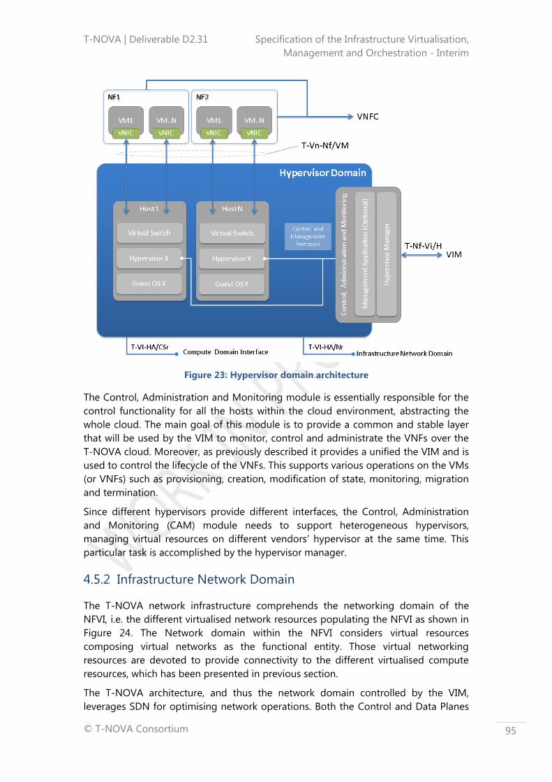
T-NOVA | Deliverable D2.31 Specification of the Infrastructure Virtualisation,
Management and Orchestration - Interim
© T-NOVA Consortium
95
Figure 23: Hypervisor domain architecture
The Control, Administration and Monitoring module is essentially responsible for the
control functionality for all the hosts within the cloud environment, abstracting the
whole cloud. The main goal of this module is to provide a common and stable layer
that will be used by the VIM to monitor, control and administrate the VNFs over the
T-NOVA cloud. Moreover, as previously described it provides a unified the VIM and is
used to control the lifecycle of the VNFs. This supports various operations on the VMs
(or VNFs) such as provisioning, creation, modification of state, monitoring, migration
and termination.
Since different hypervisors provide different interfaces, the Control, Administration
and Monitoring (CAM) module needs to support heterogeneous hypervisors,
managing virtual resources on different vendors’ hypervisor at the same time. This
particular task is accomplished by the hypervisor manager.
4.5.2 Infrastructure Network Domain
The T-NOVA network infrastructure comprehends the networking domain of the
NFVI, i.e. the different virtualised network resources populating the NFVI as shown in
Figure 24. The Network domain within the NFVI considers virtual resources
composing virtual networks as the functional entity. Those virtual networking
resources are devoted to provide connectivity to the different virtualised compute
resources, which has been presented in previous section.
The T-NOVA architecture, and thus the network domain controlled by the VIM,
leverages SDN for optimising network operations. Both the Control and Data Planes

T-NOVA | Deliverable D2.31 Specification of the Infrastructure Virtualisation,
Management and Orchestration - Interim
© T-NOVA Consortium
96
are separated. The network domain builds a full abstraction of the actual resources
included in the physical substrate and then creates vLinks between VMs (composing
vNets), which are provisioned in order to satisfy the requirements of the different
VNFs.
The main objectives of the network (aforementioned) resources are to provide
connectivity between VMs which can run on the same server, on different servers
within the same DC, or outside the same DC boundaries. (In the latter case, a co-
operation with the TNM module is required). Within the T-NOVA IVM, this is directly
translated into the creation of virtual networks that interconnect a set of compute
resources which are providing the execution substrate to VNFs.
Virtual networks must be dynamically programmed in order to ensure network
slicing, isolation, and ultimately connectivity in the T-NOVA multi-tenant scenario.
Each vNet is dedicated to a specific VNF service, and provides connectivity between
the different hosts serving the VNF service. Elasticity of the vNet is strictly required in
order to guarantee that the corresponding VNF services can be properly scaled-up or
–down. A virtualised control plane (SDN-like) will be responsible for controlling each
one of these virtual networks (refer to subsection 4.6.2).
Basically, the network domain performs abstraction of the physical network devices
themselves and then creates a set of virtual slices in an on-demand fashion. The
architecture basically contains the southbound components, with the different
resource agents and the abstracted models, with the upper part of the network
domain contains the basic virtualisation capabilities, responsible for creating and
composing the virtual networks.
The network domain contains two basic interfaces: (i) one to the VNF (T-Vn-Nf/VN),
and (ii) the other to the basic VIM controller (T-Nf-Vi/N). A full description of the
interfaces can be found in Table 7.
Figure 24: High level architecture of the Infrastructure Network

T-NOVA | Deliverable D2.31 Specification of the Infrastructure Virtualisation,
Management and Orchestration - Interim
© T-NOVA Consortium
97
4.6 Virtualised Infrastructure Management
Within the T-NOVA IVM architecture the VIM is the functional entity that is
responsible for controlling and managing the NFVI compute, storage and network
resources within the NFVI. The VIM general is expected to operate in one operator’s
infrastructure domain (e.g., NFVI-PoP). However as many operators now have data
centres distributed on a global basis, scenarios will arise where the VIM may operate
in more than one NFVI-PoP to support either the architecture requirements for VNF
services and/or operator business needs. Alternatively multiple VIMs may operate
across operator data centres providing multi NFVI-PoPs that can operate
independently or cooperatively as required under the control of an Orchestrator.
While a VIM, in general, can potentially offer specialisation in handling certain NFVI
resources, in the specific context of the T-NOVA system the VIM will handle multiple
resources types as shown in Figure 25. The VIM acts as the interface between the T-
NOVA Orchestrator and the available IT-Infrastructure abstracted by the NFVI. The
control components are at the heart of the VIM, encompassing the following
elements:
The algorithms and logic for control, monitoring and configuration of their
related domain;
An interface or API server to offer the implemented logic and collected
information’s in an abstracted way to other components;
An interface to control and access the virtualised infrastructure.
The interfaces of the API servers from each control component in the VIM are
furthermore aggregated in the Orchestrator Agent and the VNF Manager Agent to
deliver a unified interface to the upper layers of the T-NOVA components via the T-
Vi-Vnfm and T-Or-Vi interfaces. This architecture allows interaction with the upper
layers with a higher level of abstraction giving the T-NOVA Orchestrator the layers
with a higher level of abstraction giving the T-NOVA orchestrator the flexibility, to
configure a particular part of the infrastructure or to collect infrastructure related
data. The VIM also exposes southbound interfaces (as shown in Figure 25Figure 26)
to the infrastructure resources (Hypervisor/Compute/Network) of the NFVI which
enable control and management of these resources. A summary of the key north
bound VIM interfaces can be found in Table 7.

T-NOVA | Deliverable D2.31 Specification of the Infrastructure Virtualisation,
Management and Orchestration - Interim
© T-NOVA Consortium
98
Figure 25: T-NOVA VIM high level architecture
The following are the key set functions identified that must performed by T-NOVA
VIM based on general requirements identified by ETSI for a VIM within the MANO
architecture (8).
Resource catalogue management,
Orchestrating the allocation/upgrade/release/reclamation of NFVI resources,
and managing the association of the virtualised resources to the physical
compute, storage, networking resources,
Supporting the management of VNF Forwarding Graphs (create, query,
update, delete), e.g., by creating and maintaining Virtual Links, virtual
networks, sub-nets, and ports,
Management of the NFVI capacity/inventory of virtualised hardware resources
(compute, storage, networking) and software resources (e.g., hypervisors),
Management of VM software images (add, delete, update, query, copy) as
requested by other T-NOVA functional blocks (e.g., NFVO),
Collection and forwarding of performance measurements and faults/events
information relative to virtualised resources via the northbound interface to
the Orchestrator (T-Or-Vi),
Management of catalogues of virtualised resources that can be consumed
from the NFVI. The elements in the catalogue may be in the form of
virtualised resource configurations (virtual CPU configurations, types of
network connectivity (e.g., L2, L3), etc.), and/or templates (e.g., a virtual
machine with 2 virtual CPUs and 2 GB of virtual memory).
The high level architecture for the T-NOVA VIM architecture reflects these key
functions.
T-NOVA | Deliverable D2.31 Specification of the Infrastructure Virtualisation,
Management and Orchestration - Interim
© T-NOVA Consortium
99
4.6.1 IT Resource Management and Control
In the T-NOVA system we distinguish between IT and visualised network resources
Also from a management and control perspectives this categorisation is clearly visible
in the architectural design of the VIM. In fact, on the one hand, the VIM provides to
the Orchestration layer a unified access point to all infrastructural resources at an
abstracted level, but, on the other hand, internally the control modules are explicitly
split into Compute and Hypervisor Control managing the IT resources, whereas the
Network Control module manages the network resources. This architectural choice
allows the T-NOVA system to manage them according to different requirements and
needs (in terms of performance, time constraints, and so forth) The following
subsections discuss the respective management and control needs of the hypervisor
and compute resources within the VIM and their relationship to the NFVI.
4.6.1.1 Hypervisor Management
The hypervisor control function is responsible for providing high level control and
configuration capability that is independent of the technology implementation within
the hypervisor domain. The interface to the hypervisor domain (T-Nf-Vi/H) provides
the necessary level of abstraction to the specifics of the underlying hypervisor. The
hypervisor control component provides the basic commands like start, stop, reboot
etc. and offers these commands through an API server to the VIM. Specific
commands related to a particular hypervisor implementation may also be supported
on case by case basis through the same API server allowing finer performance tuning.
Additionally the hypervisor controller can implement a query API that can be used to
provide detailed information such as configuration details, version numbers etc.
The network configuration of a newly created VM is usually configured by a script
that runs at boot-time or can be done manually after the VM has booted. The
hypervisor control component will offer the capability to implement a network
configuration during VM instantiation thus enabling a higher degree of automation
which is important for service provider operations. The hypervisor controller is able to
push onto the VM, provided the hypervisor supports the action, the desired network
configuration before the first boot of the OS.
The reliability capabilities inside the hypervisor controller have an important role as
custom configurations can be requested by the T-NOVA Orchestrator. Their primary
role is to prevent the user of the API from placing the hypervisor in an inconsistent or
error state leaving it unable to manage or respond to the VMs under its control. The
module may also play a role in managing issues such as misconfiguration,
compromised commands or hypervisor options that do not work well with the
allocated hardware.
4.6.1.2 Computing Resources Management
A key functionality of the compute domain management will be the collection and
processing of the monitoring metrics collected by both the physical compute nodes
as well as the VMs (VNFCs). A dedicated monitoring manager is envisaged;, to which
monitoring agents will connect to communicate compute domain resource metrics.

T-NOVA | Deliverable D2.31 Specification of the Infrastructure Virtualisation,
Management and Orchestration - Interim
© T-NOVA Consortium
100
At the monitoring manager, these metrics will undergo statistical processing in order
to extract additional information such as fluctuation, distribution and correlation. This
processing will provide useful information about the behaviour of each VNF
component and will contribute towards the early detection of possible VNFC
malfunctions. This will be the case e.g. if some measurements fall outside the normal
VNF load curve (e.g. if CPU utilisation rises abnormally even though processed
network traffic volume does not).
The placement of a VM on a compute resource is a critical task and the compute
controller carries out this function using a placement scheduler. This scheduler will, if
no further options are specified, make a decision based on the requirements of the
infrastructure provider and place the VM in an automated fashion. To influence this
decision making process, the scheduler will have a filter API that can be used via the
Orchestrator agent and thus by the Orchestrator. The filter may have of details
related to the desired SLA or specific hardware and software requirements. The main
filter categories that influence the decision process by the scheduler are:
Specific hardware requirements like CPU speed or type of disc,
Specific software requirements like the host OS or the hypervisor,
Current load and performance metrics of the compute node such as average
CPU utilisation rate etc.,
Financial considerations such as newest hardware or most energy efficient
hardware.
A further core task of the compute controller is to provide specific management
capabilities of the VMs for the Orchestrator especially where the operations overlap
with hypervisor and network controller actions. Such tasks include:
Creation and deletion of a VM,
Rebuilding, suspend and pause a VM,
Migrating a VM from one compute node to another compute node,
Resizing a VM.
Creation of a VM requires close interaction with the base image repository that
contains the basic unmodified OS images. In many cloud computing platforms, these
base images are known as flavours.
A CLI capability is generally required within the compute controller in order to enable
infrastructure administrators to carry out routine maintenance and administration
tasks. For example, the administrators may need to migrate VMs on a physical
compute node to another one as part of an infrastructure upgrade activity. Other
potential action may include interaction with the scheduler and filters in order to
modify the configuration of a VM or set of VMs to maintain an associated SLA for a
VNF service running on the VMs.

T-NOVA | Deliverable D2.31 Specification of the Infrastructure Virtualisation,
Management and Orchestration - Interim
© T-NOVA Consortium
101
4.6.2 Infrastructure Network Resources Management and
Monitoring
The Network Control functional block within the VIM is responsible for configuring
and managing the SDN-compatible network elements to provide an abstracted
platform for running SDN applications (i.e. network virtualisation, load balancing,
access control etc.).
In order to meet specific VNF services’ requirements, the network elements, physical
and virtual, need to be properly programmed by the Network Control function to
ensure appropriate network slicing, isolation and connectivity in a multi-tenant
environment. In this way, the network will be properly partitioned and shared among
several vNets, each dedicated to a specific VNF service. In the T-NOVA architecture
there is an explicit distinction between virtual and physical network control domains:
the virtual network control domain is managed by the VIM, whereas the physical
network control domain is managed by the TNM entity (discussed in next section).
The virtualisation of the Network Control is intended to address scalability and
centralisation issues affecting the SDN controller in large network infrastructures. The
proposed approach is to virtualise each instance of CP, enabling the distribution of
the overall workload to multiple VM. In this regard, the SDN Control Plane can offer
elasticity, auto-scaling and computational load balancing by exploiting cloud-
computing capabilities.
In order to guarantee an efficient CP virtualisation, a SDN Control Plane Coordinator
is expected to manage and monitor multiple CP instances. Moreover, it maintains a
global consistent view of the network by means of a Distributed Cache among each
running CP instance.
Figure 26: VIM Network Control Architecture
The Network Control component interfaces internally with the VIM Hypervisor and
Compute components and externally with the Orchestrator layer, by accepting
requests to deploy vNets based on certain topology and QoS requirements.

T-NOVA | Deliverable D2.31 Specification of the Infrastructure Virtualisation,
Management and Orchestration - Interim
© T-NOVA Consortium
102
4.7 Transport Network Management
The ETSI specifications indicate that the NFVI is the totality of the NFVI-PoPs along
with the transport network that interconnects them. In T-NOVA architecture, there is
an explicit separation between those two domains and two different network
domains have been identified: the former involves the SDN based network which is
internal to an NFVI-PoP, whereas the latter involves the transport networks that
interconnect NFVI-PoPs.
The TNM is the module of the IVM architecture whose main function is to manage
the transport network, composed by PNFs, providing also the connectivity between
different NFVI-PoPs, relying on existing WAN networks.
Those PNFs can be classified in two different categories:
SDN-enabled network elements - physical devices that implement an SDN
approach,
Legacy network element - physical devices which do not support any SDN
programmability feature.
The NFVO interfaces to the TNM through the T-Or-TN reference point (see Annex B,
Table 28) supporting requests relating to the creation and management of virtual
networks over different NFVI-PoPs: therefore, in order for the Orchestrator to request
a virtual network connection between VNFs running in different DCs interaction with
both virtual network resources (through the VIM) and physical networks among
NFVI-PoPs (through the TNM) is required.
The TNM is invoked by the Orchestrator to setup the interconnection among
Network Controllers (NCs) belonging to different NFVI-PoPs. In fact, within a VIM,
potentially, multiple NCs are encompassed (e.g., if different virtual network
partitioning techniques are used within the domain); in this case, the VIM is
responsible for requesting virtual networks from each underlying NC and setting-up
the interworking functionality between them. Thus, at the lowest level, network
controllers have visibility to L2 network elements within the NFVI-PoP whereas, at a
higher level, the VIM provides connectivity services to the Orchestrator in a suitable
manner using the underlying resources.
The TNM is responsible for a number of key aspects related to connectivity services.
These include the following:
Management and control of existing PNFs;
Monitoring of WAN resources and virtual links in order to provide the
Orchestrator with useful statistics (such as jitter, RTT, delay, bandwidth, etc.) to
make decisions about allocation of network resources;
Management of virtual/physical links between NFVI-PoPs according to NFVO
provisioning via configuration of:
o SDN-enabled network elements, that enable network slicing
techniques,

T-NOVA | Deliverable D2.31 Specification of the Infrastructure Virtualisation,
Management and Orchestration - Interim
© T-NOVA Consortium
103
o Legacy network elements, relying on tunnelling protocols (e.g., VXLAN
(44), NVGRE (45), STT (46)) in case of L3 PNFs or on native
trunking/aggregation protocols in case of L2 PNFs (e.g. VLAN, Q-in-Q,
etc.),
Interfacing to the NFVO in order to accept provisioning requests and to
submit monitoring information.
In the following sections the management and monitoring of network resources are
discussed for both SDN-enabled and legacy network devices.
It is worth noting that the T-NOVA scope does not include elaboration on
implementation of a full solution for legacy technologies. However, existing
management solutions will be investigated in order to develop an understanding of
how to support interfacing to the NFVO in order to achieve the provisioning of the
required functions (i.e. configuration, tunnel establishment, QoS provision, failover
support etc).
4.7.1 Network Resources Management and Monitoring
The TNM plays a very important role within the IVM by providing the NFVO with an
abstracted view of the network topology and resources, (i.e. link capacities, latency,
etc.), for available WAN networks. It is common for large domains to be segmented
into different administration domains in order to increase the efficiency of both
management and monitoring. In this respect, T-NOVA expects that two types of
transport network domains will be supported: (i) the SDN Domain which comprises
SDN network elements (usually L2 devices) and (ii) the Legacy Domain which
comprises L2/L3 network elements that do not support programmability, but support
traffic engineering technologies (e.g. MPLS/IP).
4.7.1.1 SDN-enabled Network Elements
Today’s WANs are becoming more complex and the introduction of SDN aligned
approaches holds great potential for managing and monitoring network devices and
the traffic which flows over them. The benefits are mainly related to automated
network provisioning and to the flexibility in link deployment between different data
centres.
From a T-NOVA perspective, the TNM has responsibility for controlling and
monitoring the physical network devices which are SDN-enabled, with the purpose of
providing WAN connectivity between different NFVI-PoPs while considering both
SLAs required by VNFs and efficient management of cloud infrastructure resources.
In this context, the interaction with per-existent SDN will be needed to manage and
monitor network resources to get required flexibility and customisation capabilities:
TNM and VIM Network Control modules will need to be coordinated both by the
Orchestrator in an appropriate manner, in order to setup VLANs among different
virtual and physical SDN-enabled devices.
Although for the intra-DC networking the deployment of SDN technologies is
becoming more common place, the adoption of SDN at the transport level and
T-NOVA | Deliverable D2.31 Specification of the Infrastructure Virtualisation,
Management and Orchestration - Interim
© T-NOVA Consortium
104
especially at Layer 0 to 1, is still very much in its infancy (72), (73). When considering
the transport layers we encompass technologies at layer 0 (DWDM, photonics) and
layer 1 (Sonet/SDH and OTN). A key reason for the delay in SDN adoption in the
transport network is the on-going transition from the analog to digital domain. The
mechanisms for dealing with analog attributes in optical networks are vendor
specific, and it is not possible for a generic controller to deal with the current myriad
of vendor specific implementations. Nor is it possible for network operators to
remove all of their transport equipment from their networks and replace it with a
standardised optical hardware based around open standards. However, at higher
layers (i.e. WAN) the adoption path is potentially more expeditious. Companies like
Google and the Carrier Ethernet (MEF) and cloud business units of network operators
have already adopted SDN solutions for their WANs (74).
For the purpose of the T-NOVA proof-of-concept demonstration the TNM
development of SDN compatible devices, is out of scope as it is not part of the
objectives of the project which are mostly focusing on the NFVI-PoP network
management and control. However, at an architectural level it is thoroughly
supported to ensure appropriate future proofing.
4.7.1.2 Legacy Network Elements
Managing and monitoring legacy network domains is a well understood and mature
capability. A variety of standardised and proprietary frameworks have been proposed
and implemented varying from commercial to open source solutions.
As outlined in subsection 2.2.4.2 the standard method for allowing network overlays
over legacy network domain is the exploitation of L2 to L3 tunnelling mechanisms.
Those mechanisms introduce the use of tunnelling protocols that allow the
management aspects of each tunnel on an end-to-end basis. The most interesting
tunnelling protocols, from a T-NOVA architecture perspective, (as discussed in
subsection 2.2.4.2) are VxLAN, NVGRE and STT. In short these protocols allow the
interconnection of NFVI-PoPs over L3 legacy network by encapsulating the NFVI
network traffic (actually DC traffic) end-to-end. They require the setup of an end-
point for each connected DC, which is responsible for encapsulation and
decapsulation of packets.
At a WAN level the architecture design of T-NOVA supports any type of legacy WAN
technology (i.e. MPLS, Optical, Carrier Ethernet etc.) or SDN compatible, provided that
the appropriate interfaces are developed. In this context, and for the sake of
demonstrating the UC as discussed in D2.1, T-NOVA will exploit an IP/MPLS transport
network and provide a simple implementation of TNM in order to support
provisioning of vNETs in an end-to-end manner.
From a monitoring perspective, there are a number of frameworks ranging from
passive to active and hybrid that allow the monitoring of legacy networks (75), (76).
T-NOVA will employ such mechanisms in order to monitor adequately the status of
the network and more importantly the status and resource usage of the established
tunnels. Monitoring of the transport network resources will also be part of the
considered TNM functionalities that will be implemented. Moreover, the monitoring
T-NOVA | Deliverable D2.31 Specification of the Infrastructure Virtualisation,
Management and Orchestration - Interim
© T-NOVA Consortium
105
information will be conveyed to the NFVO as an input in the mapping and path
computation mechanism. Historical monitoring data collection will also be collected
to facilitate tracking of SLA breaches.
.

T-NOVA | Deliverable D2.31 Specification of the Infrastructure Virtualisation,
Management and Orchestration - Interim
© T-NOVA Consortium
106
5 T-NOVA VNFS AND NSS PROCEDURES
This section illustrates the set of most common procedures associated with the
deployment and management of VNFs (e.g. on-boarding, instantiation, monitoring,
scaling, etc.) to illustrate the interactions between the T-NOVA Orchestrator and IVM
architecture FEs that have been described in Sections 3 and 4. The flow diagrams
presented in this section serve as a means to validate the architectures for the T-
NOVA Orchestrator and IVM layers and their constituent architectural components. In
addition, the flow diagrams also illustrate the interactions at the FE level and validate
the purpose and capabilities of the interfaces that have been identified in subsections
3 and 4. As stated above, the sequence diagrams are intended to illustrate specifically
the interaction of the entities of the Orchestration and the IVM layers, however some
of the details of the internal actions of each module are not illustrated as these are
implementation specific and depend on the technologies utilised.
While a conceptual exercise, the description and illustration of the key VNF
deployment and management workflows provide a means to stress tests regarding
the taken architectural decisions and capture necessary refinements prior to
implementation related activities in WP3/4. Subsection 5.1 focuses on the VNF
procedures, whereas subsection 5.2 is centred on the NS procedures.
5.1 VNF related procedures
To describe the VNF procedures, the following assumptions are made:
The VNF is composed by one or more VNFC3s;
Each VNFC has a dedicated VM;
VNFCs are interconnected through Virtual Network Links;
The VNF, as well as the constituent VNFCs, is instantiated within a single data
centre, which implies that no scenarios involving the TNM are applicable.
The VNF details (e.g. deployment rules, scaling policies, and performance metrics) are
described in the VNF Descriptor.
5.1.1 On-boarding
VNF on-boarding (Figure 27) refers to the process of making the T-NOVA
Orchestrator aware that a new VNF is available on the NF Store.
3 A single VNF which is hosted by a single VM is called a Virtual Network Function Component
(VNFC)

T-NOVA | Deliverable D2.31 Specification of the Infrastructure Virtualisation,
Management and Orchestration - Interim
© T-NOVA Consortium
107
Figure 27: VNF On-boarding Procedure
Steps:
1. A new VNF is uploaded to the NF Store. As a result, the NF Store notifies the
NFVO that a new VNF is available.
2. The NFVO requests the metadata (VNF Descriptor) of the new VNF from the
NF Store.
3. The VNF Descriptor is provided to the NFVO.
4. The NFVO processes the VNFD to check if the mandatory elements are
provided.
5. The NFVO uploads the VNFD to the VNF Catalogue.
5.1.2 Instantiation
VNF instantiation (Figure 28 and Figure 29) refers to the process of creating and
provisioning a VNF instance. Figure 28 refers to the instantiation process from the
perspective of the Orchestration Layer, whereas Figure 29 shows the instantiation
process from the IVM layer point of view.

T-NOVA | Deliverable D2.31 Specification of the Infrastructure Virtualisation,
Management and Orchestration - Interim
© T-NOVA Consortium
108
Figure 28: VNF Instantiation Procedure (Orchestrator’s View)
Steps VNF Instantiation – Orchestrator’s View:
1. NFVO calls the VNFM to instantiate the VNF, with the instantiation data.
Optionally, and before the instantiation request from the NFVO to the
VNFM, a feasibility check could be made to ensure the required
resources for the VNF are available (and reserved) at the virtual
infrastructure (interacting with the VIM) layer.
2. The VNFM validates the request and processes it. This might include
modifying/complementing the input instantiation data with VNFD data and
VNF lifecycle specific constraints.
3. The VNFM then calls the NFVO for resource allocation.

T-NOVA | Deliverable D2.31 Specification of the Infrastructure Virtualisation,
Management and Orchestration - Interim
© T-NOVA Consortium
109
4. The NFVO retrieves VNF image(s) from the NF Store.
5. NF Store delivers the VNF image(s) to the NFVO.
6. The NFVO executes any required pre-allocation processing work.
VNF location selection: The selection of where to locate a VNF
instance could be based on the request, available resources, the nature
of the VNF, the Network Service(s) in which the VNF instance is
participating in as well as defined policies.
Resource pool selection: The resource pool to be used needs to be
selected. Note that this is not the same as the VNF location. Multiple
resource pools could exist in the same location or some VNFCs that
are part of a VNF instance may need to be located remotely from the
rest.
Dependency checking: Availability of all the required external
dependencies from the required location need to be checked. If the
VNF instance has any QoS requirements, it also needs to be verified if
they can be met in the selected location. Note that the QoS
requirements could be on compute or network resources, or on
external services on which the VNF instance is dependent.
7. The NFVO requests the allocation of resources from the VIM (compute,
storage and network) needed for the VNF instance (and delivers the VNF
image(s)).
8. The VIM instantiates the required compute and storage resources from the
infrastructure, for further details see VNF Instantiation Procedure – IVM View.
9. The VIM instantiates the internal connectivity network – a VNF may require
dedicated virtual networks to interconnect it’s VNFCs (networks that are only
used internally to the VNF instance), for further details see VNF Instantiation
Procedure – IVM’s View.
10. The VIM interconnects the instantiated internal connectivity network with the
VNFCs, for further details see VNF Instantiation Procedure – IVM View.
11. Acknowledgement of completion of resource allocation back to NFVO.
12. The NFVO acknowledges the completion of the resource allocation back to
VNFM, returning appropriate configuration information.
13. After the VNF is instantiated, the VNFM configures the VNF with any VNF
specific lifecycle parameters (deployment parameters).
14. The VNF sends an acknowledgement to the VNFM that the configuration
process is completed.
15. The VNFM notifies the EM (if present) of the new VNF, step outside the scope
of T-NOVA.
16. The EM acknowledges the VNFM, step outside the scope of T-NOVA.

T-NOVA | Deliverable D2.31 Specification of the Infrastructure Virtualisation,
Management and Orchestration - Interim
© T-NOVA Consortium
110
17. The EM configures the VNF with application-level parameters and
acknowledges the VNFM, step outside the scope of T-NOVA.
18. The VNFM acknowledges the completion of the VNF instantiation back to the
NFVO.
The diagram corresponding to steps 8-10 is indicated below.
Figure 29: VNF Instantiation Procedure (IVM’s View)
The specifics details of steps 8-10 are as follows:
8.1. The VIM Orchestrator Agent submits a request to the VIM Compute
Control module to create new VMs, according to the VNF requirements.
8.2. The VIM Compute Control module:
Processes the request;
Analyses the required configuration;
Selects one or more suitable compute nodes to host the VMs;

T-NOVA | Deliverable D2.31 Specification of the Infrastructure Virtualisation,
Management and Orchestration - Interim
© T-NOVA Consortium
111
Sends request to allocate VMs to the selected nodes.
8.3. The selected NFVI Compute node(s) allocates the VMs.
8.4. The NFVI Compute nodes send back an acknowledgment to the VIM
Compute Control module when they successfully boot.
8.5. The VIM Compute Control module sends back an acknowledgment to the
VIM Orchestrator Agent.
9.1. The VIM Orchestrator Agent submits a request to the VIM Network Control
module for the allocation of Network Resources.
9.2. The VIM Network Control module:
Processes the request;
Analyses the required configuration;
Sends a request for allocation of virtual network resources on the NFVI
Network.
9.3. The NFVI Network:
Allocates the resources;
Sets up the virtual networks, by configuring the required
interconnectivity between virtual switches.
9.4. The NFVI Network sends back an acknowledgment to the VIM Network
Control module.
9.5. The VIM Network Control module sends back an acknowledgment to the
VIM Orchestrator Agent.
10.1. The VIM Orchestrator Agent submits a request to the VIM Hypervisor
Control module to attach the new VMs to the required virtual networks.
10.2. The VIM Hypervisor Control module sends the request to the hypervisors
controlling the new VM hosting nodes.
10.3. The hypervisors of those nodes:
Configure the vSwitches in order to manage the VLANs connectivity
necessary to support the VNF requirements;
Setup the interconnections among VMs and vSwitches.
10.4. The hypervisors send back acknowledgments to the VIM Hypervisor
Control module.
10.5. The VIM Hypervisor Control module sends back an acknowledgment to the
VIM Orchestrator Agent.
5.1.3 Supervision
VNF supervision from the Orchestrator’s layer point of view (Figure 30) refers to the
process of monitoring of the VNF, including the infrastructure specific parameters

T-NOVA | Deliverable D2.31 Specification of the Infrastructure Virtualisation,
Management and Orchestration - Interim
© T-NOVA Consortium
112
collected and reported by the IVM, as well as the VNF application/service-specific
parameters.
VNF supervision from the IVM’s layer point of view (Figure 31) refers to the process of
monitoring of the VIM, including the VM performance metrics, the VL performance
metrics, and the physical machines performance metrics.
As far as the supervision procedure from the Orchestrator’s layer point of view is
concerned, the sequence is as follows:
Figure 30: VNF Supervision Procedure (Orchestrator’s View)
Steps (VNF Supervision – Orchestrator’s View):
1. VNF collects performance metrics related with the VNF application/service.
2. VNF notifies the VNFM with the VNF application specific metrics:
As a result, the VNFM may decide to scale the VNF and/or provide
aggregated monitoring information towards the NFVO.
3. VIM collects performance metrics related with the infrastructure allocated for
the VNF, for further details see VNF Supervision Procedure – IVM View.
4. VIM notifies the VNFM with the VNF infrastructure related performance
metrics.

T-NOVA | Deliverable D2.31 Specification of the Infrastructure Virtualisation,
Management and Orchestration - Interim
© T-NOVA Consortium
113
As a result, the VNFM may decide to scale the VNF and/or provide aggregated
monitoring information towards the NFVO. As far as the supervision procedure from
the IVM’s layer point of view is concerned, the sequence is as follows:
Figure 31: VNF Supervision Procedure (IVM’s View)
Steps (VNF Supervision – IVM’s View):
5.1. The NFVI Hypervisors:
Collect VM performance metrics data;
Send the data to the VIM Hypervisor Control module.
5.2. The VIM Hypervisor Control module sends the data to the VIM VNF Manager
Agent.
5.3. The NFVI Network devices:
Collect performance metrics data from virtual network links (VLs);
Send the data to the VIM Network Control module.
5.4. The VIM Network Control module sends the collected data to the VIM VNF
Manager Agent.
5.5. The NFVI Compute nodes:
Collect the physical performance metrics data;
Send the data to the VIM Compute Control module.
5.6. The VIM Compute Control module sends the data to the VIM VNF Manager
Agent.

T-NOVA | Deliverable D2.31 Specification of the Infrastructure Virtualisation,
Management and Orchestration - Interim
© T-NOVA Consortium
114
5.1.4 Scale-out
VNF scale-out refers to the process of creating a new VM to increase the VNF
capacity with additional compute, storage, memory and network resources.
The scaling policies that indicate which/how/when VMs/VNFCs should be scaled are
identified in the ”VNF Deployment Flavour” attribute, which makes part of the VNF
Descriptor (VNFD).
Figure 32 illustrates this case for a scaling-out: VNFC A is instantiated and a new VL is
created to connect this new instance to the existing VNFC B instance. VNF scaling is
further detailed on another deliverable of this project, D2.41 (62).
Figure 32: Scaling out a VNF
Figure 33 illustrates the VNF scale-out process where it is the VNFM that decides to
scale the VNF, after receiving VNF application/service specific metrics from the VNF
and VNF infrastructure related metrics from the VIM:

T-NOVA | Deliverable D2.31 Specification of the Infrastructure Virtualisation,
Management and Orchestration - Interim
© T-NOVA Consortium
115
Figure 33: VNF Scale-out Procedure
Steps:

T-NOVA | Deliverable D2.31 Specification of the Infrastructure Virtualisation,
Management and Orchestration - Interim
© T-NOVA Consortium
116
1. The VNFM collects performance metrics related with the VNF
application/service (from the VNF) and with the infrastructure resources (from
the VIM), for further information about the performance metrics collection,
check the “VNF Supervision Procedure”.
2. Based on the retrieved performance metrics and on the auto-scaling policies
(included in the VNFD), the VNFM detects the need to scale.
3. The VNFM decides that the best option is to scale-out the VNF.
4. The VNFM requests the NFVO to scale-out the VNF by indicating the required
resources for the new VM – matching a specific “VNF deployment flavour”
from the VNFD stored in the VNF Catalogue.
NFVO may perform a VNF feasibility check where a resource reservation is
made in the VIM (further information on the VNF Instantiation Procedure-
Orchestrator’s View).
5. The NFVO executes any required pre-allocation processing work, e.g. VNF
location selection, Resource pool selection, Dependency checking, for further
details see VNF Instantiation Procedure – Orchestrator’s View.
6. The NFVO requests allocation of resources from the VIM (compute, storage
and network) needed for the VNF instance (and delivers the VM image(s)).
7. The VIM instantiates the required compute and storage resources from the
infrastructure (according to the new “VNF Deployment Flavour” attribute), for
further details see VNF Instantiation Procedure – IVM’s View.
8. The VIM instantiates the internal connectivity network – a VNF may require
dedicated virtual networks links (VLs) to interconnect its VNFCs (networks that
are only used as internal to the VNF instance), for further details see VNF
Instantiation Procedure – IVM’s View.
9. Thereafter the VIM interconnects the instantiated internal connectivity
network with the VNFCs (according to the “VNF Lifecycle Script & VLD”
attribute), for further details see VNF Instantiation Procedure – IVM’s View.
10. Acknowledgement of completion of resource allocation is sent back to NFVO.
11. NFVO acknowledges the completion of the scale-out/resource allocation back
to VNFM, returning appropriate configuration information.
Thereafter the VNFM proceeds with the VNF configuration procedures,
as described in the “VNF Instantiation Procedure - Orchestrator’s
View”.
5.1.5 Termination
VNF termination Figure 34 and Figure 35 refer to the process of releasing a VNF
instance, including the network and VM resources allocated to it. Figure 34 refers to
the termination process from the perspective of the Orchestrator’s layer, whereas
Figure 35 shows the termination process from the IVM internal point of view.
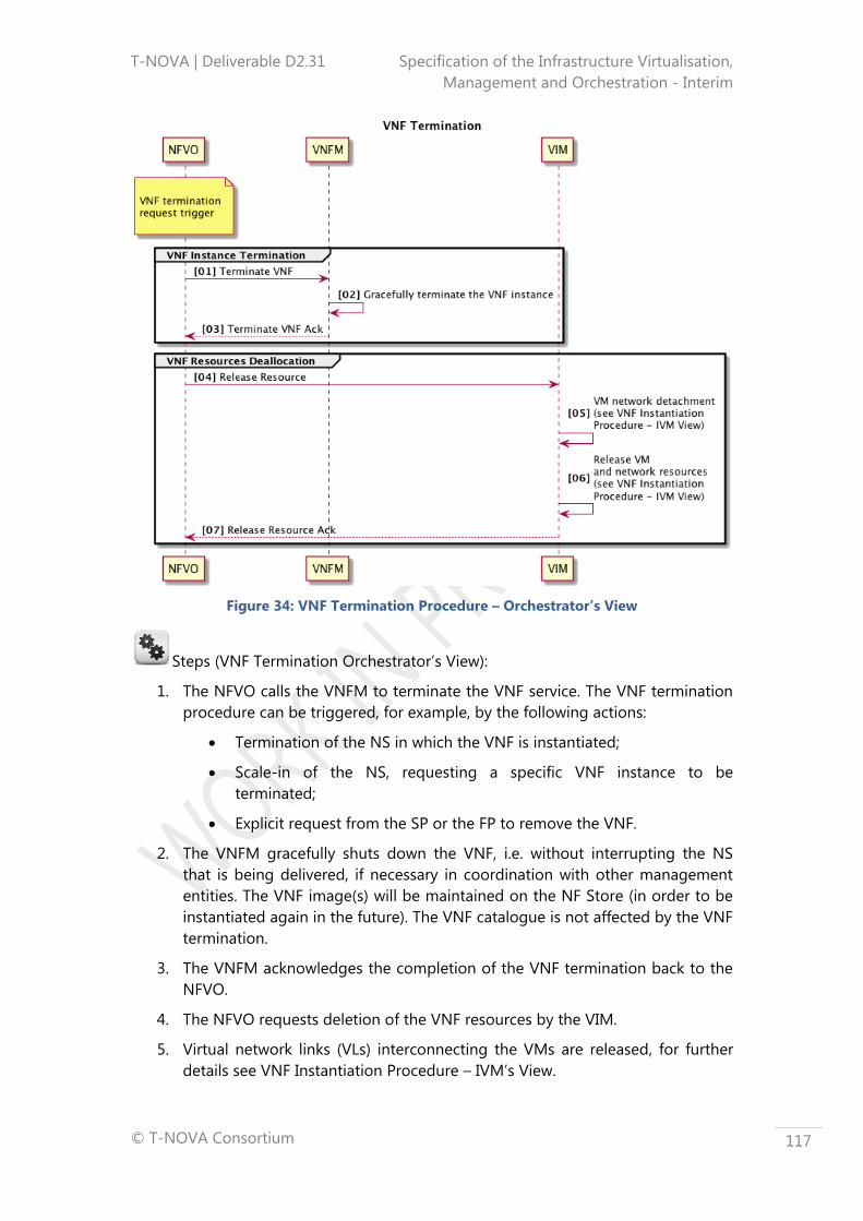
T-NOVA | Deliverable D2.31 Specification of the Infrastructure Virtualisation,
Management and Orchestration - Interim
© T-NOVA Consortium
117
Figure 34: VNF Termination Procedure – Orchestrator’s View
Steps (VNF Termination Orchestrator’s View):
1. The NFVO calls the VNFM to terminate the VNF service. The VNF termination
procedure can be triggered, for example, by the following actions:
Termination of the NS in which the VNF is instantiated;
Scale-in of the NS, requesting a specific VNF instance to be
terminated;
Explicit request from the SP or the FP to remove the VNF.
2. The VNFM gracefully shuts down the VNF, i.e. without interrupting the NS
that is being delivered, if necessary in coordination with other management
entities. The VNF image(s) will be maintained on the NF Store (in order to be
instantiated again in the future). The VNF catalogue is not affected by the VNF
termination.
3. The VNFM acknowledges the completion of the VNF termination back to the
NFVO.
4. The NFVO requests deletion of the VNF resources by the VIM.
5. Virtual network links (VLs) interconnecting the VMs are released, for further
details see VNF Instantiation Procedure – IVM’s View.

T-NOVA | Deliverable D2.31 Specification of the Infrastructure Virtualisation,
Management and Orchestration - Interim
© T-NOVA Consortium
118
6. VMs resources (compute, storage and memory) used by the VNF are released,
for further details see VNF Instantiation Procedure – IVM’s View.
7. An acknowledgement is sent indicating the success or failure of resource
release back to NFVO.
The NFVO updates the infrastructure resources repository.
Figure 35: VNF Termination Procedure – IVM’s View
Steps (VNF Termination – IVM’s View):
5.1. The VIM Orchestrator Agent submits a request to the VIM Hypervisor
Controller for detaching VM(s) from the virtual network;
5.2. The VIM Hypervisor Control module forwards the request to the NFVI
Hypervisors involved;
5.3. The NFVI Hypervisors detach VM(s) from the network;
5.4. The NFVI Hypervisors send back an Acknowledgement to the VIM Hypervisor
Control;
5.5. The VIM Hypervisor Control sends back an Acknowledgement to the VIM
Orchestrator Agent;
6.1. The VIM Orchestrator Agent submits a request to the VIM Network Controller
for releasing virtual network resources;
6.2. The VIM Network Control module forwards the request to the NFVI Network
domain;

T-NOVA | Deliverable D2.31 Specification of the Infrastructure Virtualisation,
Management and Orchestration - Interim
© T-NOVA Consortium
119
6.3. The NFVI Network Infrastructure releases the network resources and sends
back an Ack;
6.4. The VIM Network Control sends back an Ack to the VIM Orchestrator Agent;
6.5. The VIM Orchestrator Agent submits a request to the VIM Compute
Controller for releasing virtual compute resources;
6.6. The VIM Compute Control module forwards the request to the involved NFVI
Compute nodes;
6.7. The NFVI Compute nodes releases the compute resources and sends back
an Ack;
6.8. The VIM Compute Control sends back an Ack to the VIM Orchestrator Agent.
5.2 NS related procedures
To describe the NS procedures, the following assumptions are made:
The NS is composed by one or more VNFs (in the following procedures, two
VNFs – VNF1 and VNF2 – compose the NS);
VNFs composing the NS are interconnected through Virtual Network Links (if
VNFs run on the same DC) or through Non-virtual/legacy Network Links (if
VNFs run on different DCs) (in the following procedures, VNF1 runs on DC1
and VNF2 runs on DC2);
The NS constituent VNFs can be implemented in a single DC or spread across
several DCs;
Besides VNFs, PNFs can also be part of the NS (in the following procedures,
PNF1 is interconnected with VNF1).
The NS details (e.g. deployment rules, scaling policies, performance metrics, etc) are
described in the NSD, e.g. VNF Forwarding Graph for detailing the VNFs
interconnections.
5.2.1 On-boarding
NS on-boarding (Figure 36) refers to the process of submitting a NSD to the NFV
Orchestrator in order to be included in the catalogue.
Figure 36: NS On-boarding Procedure
Steps:

T-NOVA | Deliverable D2.31 Specification of the Infrastructure Virtualisation,
Management and Orchestration - Interim
© T-NOVA Consortium
120
1. The Marketplace submits the NSD to the NFVO for on-boarding the NS.
2. NFVO processes the NSD to check if the mandatory elements are provided.
3. NFVO notifies the catalogue for insertion of the NSD.
4. NFVO acknowledges the NS on-boarding.
5.2.2 Instantiation
NS instantiation refers to the instantiation of a new NS, i.e. Figure 37 from the
Orchestrator’s view, and Figure 38 from the IVM’s view.
As stated above, the next sequence diagram depicts a situation where VNFs
composing the NS run on different DCs and are interconnected through Non-
virtual/legacy Network Links.
Figure 37: NS Instantiation Procedure (Orchestrator’s View)
Steps (Orchestrator View):
1. The NFVO receives a request to instantiate a new NS.
2. The NFVO validates the request, both validity of request (including validating
that the sender is authorised to issue this request) and confirming the
parameters passed are technically correct.

T-NOVA | Deliverable D2.31 Specification of the Infrastructure Virtualisation,
Management and Orchestration - Interim
© T-NOVA Consortium
121
3. The Orchestrator checks the NS composition (e.g. VNFFG) in the NS
catalogue:
Thereafter, a feasibility check procedure may optionally be carried out
for each VNF that is part of the NS, in this case VNF1 and VNF2 For
further details about the “VNF Feasibility Check”, please see the “VNF
Instantiation Procedure”;
The NFVO triggers the instantiation of the VNFs (VNF1 and VNF2). For
further details about the “VNF Instantiation”, please check the “VNF
Instantiation Procedure”.
4. The NFVO executes any required pre-allocation processing work, e.g. VNF
location selection, Resource pool selection, Dependency checking. For further
details see VNF Instantiation Procedure – Orchestrator’s View.
5. The NFVO requests the TNM to setup the WAN resources required for
interconnecting the VNFs across the DCs (resource phase establishment).
6. The TNM configures the WAN resources between DC1 and DC2.
7. The TNM sends an acknowledgment to the NFVO reporting that the WAN has
been configured as requested.
8. The NFVO sends a request to the VIM to interconnect the WAN ingress and
egress routers to the DC VLANs (connectivity phase establishment).
9. The VIM interconnects the configured WAN resources with VNF1 and VNF2 in
DC1 and DC2, respectively.
10. The VIM acknowledges completion of the WAN / VLANs configuration:
If necessary, NFVO requests Network Manager to connect VNF
external interfaces to PNFs interfaces:
1. The Network Manager can be an OSS, an NMS or an EM;
2. Connection to PNFs is assumed to be done by the NFVO.
11. The NFVO acknowledges completion of the NS instantiation.

T-NOVA | Deliverable D2.31 Specification of the Infrastructure Virtualisation,
Management and Orchestration - Interim
© T-NOVA Consortium
122
Figure 38: NS Instantiation Procedure (IVM’ View)
Steps (IVM View):
6.1. The TNM Orchestrator Agent sends the request to the TNM Network Control
to configure the WAN end points.
6.2. The TNM Network Control configures the endpoints.
6.3. The TNM Network Control sends an acknowledgement indicating success or
failure of the configuration setup to the TNM Orchestrator Agent.
9.1. When the acknowledgement of a successful WAN configuration is received
the NFVO sends a request to the VIM Orchestrator Agent to connect a VLAN
to WAN endpoints. The VIM Orchestrator Agent sends the request to connect
a VLAN to WAN endpoints to the VIM Network Controller.
9.2. The VIM Network Controller sends the request to connect a VLAN to WAN
endpoints to the NFVI Network.
9.3. The NFVI Network connects the VLAN to the WAN endpoints.
9.4. The NFVI endpoint sends an acknowledgement of a successful or failed
connection configuration to the VIM Network Controller.
9.5. The VIM Network Controller sends an acknowledgement of a successful or
failed connection to the VIM Orchestration Agent.

T-NOVA | Deliverable D2.31 Specification of the Infrastructure Virtualisation,
Management and Orchestration - Interim
© T-NOVA Consortium
123
5.2.3 Supervision
NS supervision (Figure 39) refers to the monitoring of the NS performance metrics,
including:
VNF infrastructure and service specific information;
Network links interconnecting the VNF (across multiple DCs).
Again, as stated above, the next sequence diagram depicts a situation where VNFs
composing the NS run on different DCs and are interconnected through Non-
virtual/legacy Network Links.
Figure 39: NS Supervision Procedure
Steps:

T-NOVA | Deliverable D2.31 Specification of the Infrastructure Virtualisation,
Management and Orchestration - Interim
© T-NOVA Consortium
124
1. The VNFM sends performance metrics related to a VNF to the NFVO. This
includes both metrics from the infrastructure supporting the VNF (VMs,
Virtual Links) – obtained directly from the VIM - as well as
application/service-specific metrics from the VNF - obtained directly from
the VNF or from the EM). For further details about the VNF performance
metrics retrieval, please check the “VNF Supervision Procedure”, where the
option to forward aggregated information to NFVO has been taken by the
VNFM.
2. The TNMNetCtrl fetches and delivers the WAN segment metrics to the
TNMOrchAg.
3. The TNMOrchAg provides the WAN segment performance metrics to the
NFVO.
4. The VIM delivers VM-related metrics to the NFVO:
Based on the metrics received (VNFM, VIM and TNM) and on the
defined scaling policies included in the NSD, the NFVO may decide to
trigger a scaling procedure. Furthermore, if configured, the NFVO will
also deliver aggregated NS-related performance metrics to the
Marketplace.
5.2.4 Scale-out
NS scale-out refers to the process of increasing the capacity of the service in order to
accomplish a SLA that is changing to a new NS deployment flavour, or to maintain an
existing SLA.
The scale-out policies are triggered based on the following information:
NS issues (retrieved from VNFM);
VNF issues (retrieved from VNFM);
WAN segment, i.e. connecting VNFs issues, retrieved from TNM.
Figure 40 illustrates NS scaling case, where a second instance of VNF B is created and
the existing VNF A instance is reconfigured so that it becomes able to communicate
with the two VNF B instances.

T-NOVA | Deliverable D2.31 Specification of the Infrastructure Virtualisation,
Management and Orchestration - Interim
© T-NOVA Consortium
125
Figure 40: Scaling-out a NS
Figure 41 refers to a situation where, according to the metrics received, the required
performance of the SLA cannot be achieved. As such the NFVO decides to scale-out
to a new deployment flavour, taking also into account the auto-scaling policies
included in the NSD. This implies:
Scale-out a specific VNF to a new deployment flavour (included in this
workflow);
Creation of a new VNF instance (included in this workflow);
Changing the VNF location to another DC (not included in this workflow);
Increasing the WAN segment network link capacity (included in this
workflow).

T-NOVA | Deliverable D2.31 Specification of the Infrastructure Virtualisation,
Management and Orchestration - Interim
© T-NOVA Consortium
126
Figure 41: NS Scale-out
Steps:
1. The NFVO collects and checks monitoring information from the VNF, VIM and
the WAN.

T-NOVA | Deliverable D2.31 Specification of the Infrastructure Virtualisation,
Management and Orchestration - Interim
© T-NOVA Consortium
127
2. Based on the retrieved performance metrics and on the auto-scaling policies
defined on the NSD, the NFVO detects the need to scale-out the NS.
3. The NFVO decides to change to another NS deployment flavour, which
comprises the VNF1 scale-out, a new instantiation of VNF2#2 and an increase
on the WAN link capacity:
The other procedures (VNF scale-out, VNF instantiation and WAN
interconnection) have already been described in the previous
workflows.
5.2.5 Termination
NS termination (Figure 42) refers to the process of releasing the NS instance,
including the constituent VNFs (VNF1, VNF2#1 - instance 1 of VNF2 and VNF2#2 –
instance 2 of VNF2), as well as the WAN segment.
Figure 42: NS Termination Procedure
5.3 NS, VNF and Infrastructure Monitoring
Proper NS/VNF as well as infrastructure monitoring is crucial for the implementation
of many of the use cases foreseen for the T-NOVA system, see D2.1 (63). Especially
UC2 (Provision NFV services), UC3 (Reconfigure/Rescale NFV services) and UC5 (Bill
NFV services) use the monitoring metrics, which are collected during UC4

T-NOVA | Deliverable D2.31 Specification of the Infrastructure Virtualisation,
Management and Orchestration - Interim
© T-NOVA Consortium
128
(Monitoring). Specifically, the latter presents an overview of the T-NOVA monitoring
procedures, focusing on both:
1. VNF and Service Monitoring - related to the status and resources of the
provisioned services, as well as,
2. Infrastructure Monitoring - related to the status and resources of the physical
infrastructure.
Monitoring metrics are mostly collected at the various domains of the Infrastructure
layer and communicated to the upper layers. Figure 43 depicts a high-level view of
the flow of the monitoring information across the T-NOVA system.
Figure 43: Communication of monitoring information across the T-NOVA system
The first step is the collection of both Infrastructure and NS/VNF monitoring metrics
from different domains within the T-NOVA Infrastructure layer. These metrics are
typically offered by a dedicated monitoring agent at each physical or virtual
infrastructure element. In addition, some compute node and VNF/VM metrics can be
VNF
Marketplace
Orchestrator
Virtualised Infrastructure ManagementTransport Network
Management
Compute Storage
Infrastru-cture
Network
Transport Network
Hypervisor
Service and Infrastructure
Monitoring (VNFM / NFVO)
AccountingSLA
ManagementDashboard
VNF
NS/VNF Instances Records
Infrastructure Resources Records
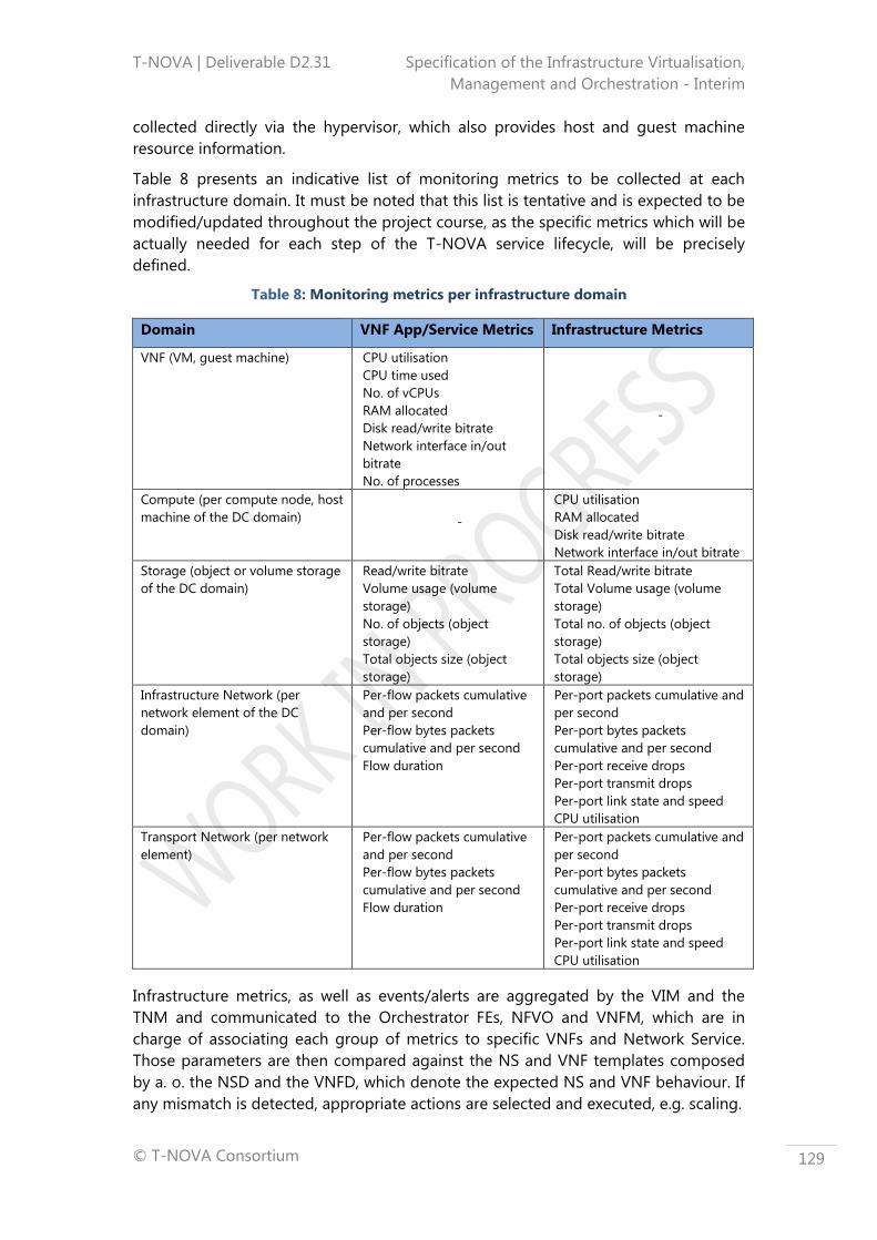
T-NOVA | Deliverable D2.31 Specification of the Infrastructure Virtualisation,
Management and Orchestration - Interim
© T-NOVA Consortium
129
collected directly via the hypervisor, which also provides host and guest machine
resource information.
Table 8 presents an indicative list of monitoring metrics to be collected at each
infrastructure domain. It must be noted that this list is tentative and is expected to be
modified/updated throughout the project course, as the specific metrics which will be
actually needed for each step of the T-NOVA service lifecycle, will be precisely
defined.
Table 8: Monitoring metrics per infrastructure domain
Domain VNF App/Service Metrics Infrastructure Metrics
VNF (VM, guest machine) CPU utilisation
CPU time used
No. of vCPUs
RAM allocated
Disk read/write bitrate
Network interface in/out
bitrate
No. of processes
-
Compute (per compute node, host
machine of the DC domain) -
CPU utilisation
RAM allocated
Disk read/write bitrate
Network interface in/out bitrate
Storage (object or volume storage
of the DC domain)
Read/write bitrate
Volume usage (volume
storage)
No. of objects (object
storage)
Total objects size (object
storage)
Total Read/write bitrate
Total Volume usage (volume
storage)
Total no. of objects (object
storage)
Total objects size (object
storage)
Infrastructure Network (per
network element of the DC
domain)
Per-flow packets cumulative
and per second
Per-flow bytes packets
cumulative and per second
Flow duration
Per-port packets cumulative and
per second
Per-port bytes packets
cumulative and per second
Per-port receive drops
Per-port transmit drops
Per-port link state and speed
CPU utilisation
Transport Network (per network
element)
Per-flow packets cumulative
and per second
Per-flow bytes packets
cumulative and per second
Flow duration
Per-port packets cumulative and
per second
Per-port bytes packets
cumulative and per second
Per-port receive drops
Per-port transmit drops
Per-port link state and speed
CPU utilisation
Infrastructure metrics, as well as events/alerts are aggregated by the VIM and the
TNM and communicated to the Orchestrator FEs, NFVO and VNFM, which are in
charge of associating each group of metrics to specific VNFs and Network Service.
Those parameters are then compared against the NS and VNF templates composed
by a. o. the NSD and the VNFD, which denote the expected NS and VNF behaviour. If
any mismatch is detected, appropriate actions are selected and executed, e.g. scaling.

T-NOVA | Deliverable D2.31 Specification of the Infrastructure Virtualisation,
Management and Orchestration - Interim
© T-NOVA Consortium
130
This procedure needs to be carried out at the Orchestrator level, since only the latter
has the entire view of the end-to-end service as well as the resources allocated to it.
In this context, and in addition to the double check (NS and VNF) mentioned above,
the monitoring processed at the Orchestrator, as part of the NFVO and VNFM,
performs the following operations:
Aggregate infrastructure-related metrics and update the Infrastructure
Resources records,
Associates metrics (e.g. VM and flow metrics) to specific services, produce an
integrated picture of the deployed service and updates the NS/VNF instances
records,
Checks monitored parameters against the NS and VNF templates, composed
by the NSD and the VNFD, which denote the expected NS and VNF behaviour.
If any mismatch is detected, appropriate actions are selected and executed,
e.g. scaling,
Communicate service metrics to the Marketplace via the Orchestrator
northbound interface.
At the Marketplace level, service metrics are exploited for accounting (especially in
pay-as-you-go billing models) as well as SLA Management, in order to compare the
status of the service against the contracted one. They are also presented via the
Dashboard to the Customer, so that he/she can have a consolidated overall view of
the status of the service and the resources consumed.

T-NOVA | Deliverable D2.31 Specification of the Infrastructure Virtualisation,
Management and Orchestration - Interim
© T-NOVA Consortium
131
6 GAP ANALYSIS
Considering both existing industry oriented initiatives and currently available
technologies that are being used commercially (or are in a development stage) a
focused gap analysis was carried out to determine what steps need to be taken in
order to move NFV/SDN from its current state to a position that can fully realise the
needs of key areas that need to be addressed during the project activities. In the
following, key results of this gap analysis are described, for all the various domains
relating to the T-NOVA Orchestrator and T-NOVA IVM architectures. Where possible
the gaps have been aligned with T-NOVA tasks where these could be either
elucidated or progressed towards addressing the gap could be made.
6.1 Compute
The Compute domain of the T-NOVA architecture provides basic building blocks for
VNFs execution. Gap analysis for this domain identified two key areas that need to be
addressed during the project activities:
Table 9: Gap analysis in the compute domain
Gap Description T-Nova
Task Alignment
Virtualisation
infrastructure for
telecommunication
workloads
Features requested by workloads need to
be investigated in greater detail and
special purpose processors (or co-
processors) have to be integrated in
compute domain infrastructures.
Those enhanced features have also to be
exposed to the upper layer of the
architecture, in order to make them
available from an orchestration
perspective
Task 3.2
Task 4.1
Interoperability between
different hardware
architectures
Compute architecture heterogeneity
needs to be improved in current compute
domain infrastructure to provide a greater
diversity of options for certain NFV
workload types.
Support for heterogeneity should not only
apply in terms of multi-vendor
technologies, but also in terms of different
hardware architectures required by
different VNFs.
Task 4.1
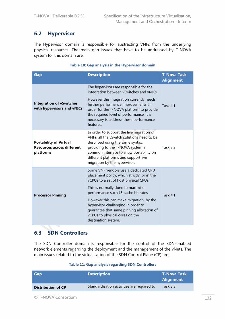
T-NOVA | Deliverable D2.31 Specification of the Infrastructure Virtualisation,
Management and Orchestration - Interim
© T-NOVA Consortium
132
6.2 Hypervisor
The Hypervisor domain is responsible for abstracting VNFs from the underlying
physical resources. The main gap issues that have to be addressed by T-NOVA
system for this domain are:
Table 10: Gap analysis in the Hypervisor domain
Gap Description T-Nova Task
Alignment
Integration of vSwitches
with hypervisors and vNICs
The hypervisors are responsible for the
integration between vSwitches and vNICs.
However this integration currently needs
further performance improvements. In
order for the T-NOVA platform to provide
the required level of performance, it is
necessary to address these performance
features.
Task 4.1
Portability of Virtual
Resources across different
platforms
In order to support the live migration of
VNFs, all the vSwitch solutions need to be
described using the same syntax,
providing to the T-NOVA system a
common interface to allow portability on
different platforms and support live
migration by the hypervisor.
Task 3.2
Processor Pinning
Some VNF vendors use a dedicated CPU
placement policy, which strictly ‘pins’ the
vCPUs to a set of host physical CPUs.
This is normally done to maximise
performance such L3 cache hit rates.
However this can make migration `by the
hypervisor challenging in order to
guarantee that same pinning allocation of
vCPUs to physical cores on the
destination system.
Task 4.1
6.3 SDN Controllers
The SDN Controller domain is responsible for the control of the SDN-enabled
network elements regarding the deployment and the management of the vNets. The
main issues related to the virtualisation of the SDN Control Plane (CP) are:
Table 11: Gap analysis regarding SDN Controllers
Gap Description T-Nova Task
Alignment
Distribution of CP Standardisation activities are required to Task 3.3

T-NOVA | Deliverable D2.31 Specification of the Infrastructure Virtualisation,
Management and Orchestration - Interim
© T-NOVA Consortium
133
workloads mitigate various scalability and availability
issues due to SDN Control plane
centralization, where a distribution
approach would have also to be
considered.
Task 4.2
Bottleneck Avoidance
Standardisation activities are required to
address large-scale, high load
deployment scenarios to avoid
bottlenecks where a distribution
approach would necessitate consideration
Task 3.3
Task 4.2
Interoperability of different
controllers
Currently a uniform interface for all the
SDN controllers does not exist, which
increases both the complexity of
development process. Work is required in
the abstraction of north bound interfaces
to support application developers.
Task 4.3
6.4 Cloud Controllers
The Cloud Controller represents the central management system for cloud
deployments. Ranging from basic to more advanced, the T-NOVA project will
investigate gaps in the current solutions within this domain, which fall short with
respect to the following aspects:
Table 12: Gap analysis regarding Cloud Controllers
Gap Description T-NOVA Task
Alignment
Interoperability between
different Cloud Computing
Platforms
From a T-NOVA Orchestrator perspective,
a unified southbound interface is needed,
in order to make the API of different IaaS
providers accessible and to enable
communications with different Cloud
Computing Platforms. Even if most cloud
platforms have widely adopted open
standards, there are still inconsistencies
with respect to the different versions and
APIs, inconsistencies that need to be
concealed under a single interface.
Task 3.1
Resource Allocation and
Configuration
From a T-NOVA VNF perspective, cloud
controllers need to support the allocation
and configuration of network resources
and allow enhanced resource
management.
Existing cloud management solutions
need to be extended to provide an
interface that would allow, for instance,
enhanced configuration of network
Task 3.2
Task 3.3
Task 3.4

T-NOVA | Deliverable D2.31 Specification of the Infrastructure Virtualisation,
Management and Orchestration - Interim
© T-NOVA Consortium
134
parameters.
Providing infrastructure
utilisation data
Monitoring and collecting information
with respect to the current load and
availability of resources is a crucial
capability for T-NOVA system, as it will be
a cloud management framework that
needs to perform in real-time and
support very high volume traffic.
Although cloud platforms already offer
monitoring capabilities, the challenge
with respect to T-NOVA is to collect the
information that is relevant for VNFs and
how to represent it such that the
Orchestration layer can best utilise it.
Task 3.2
Task 3.4
Task 4.1
Platform Awareness
Cloud environments need to become
more aware of the features and
capabilities of their constituent resources
and to expose these enhanced platform
features to the Orchestration layer to
improve the placement decisions of
workloads such as VNFs.
A common data model to describe
resources is needed, which could be used
to identify specific features like DPDK
enablement or SR-IOV capable devices.
Task 3.2
Task 4.1
6.5 Network Virtualisation
Network virtualisation introduces several gaps and open issues that need to be
addressed by the T-NOVA project:
Table 13: Gap analysis regarding Network Virtualisation
Gap Description T-NOVA Task
Alignment
Network resource isolation
VNs are by definition based on shared
resources and this brings up the
isolation problem, especially when the
number of VNs sharing the same
infrastructure is very high.
On the other hand, the strictness of
isolation varies according to the
specific use case. In a Network as-a-
Service scenario isolation it will
obviously be a fundamental
requirement.
Isolation is required between the VNs
Task 4.2

T-NOVA | Deliverable D2.31 Specification of the Infrastructure Virtualisation,
Management and Orchestration - Interim
© T-NOVA Consortium
135
running separate Telco services. Within
the T-NOVA platform, a VN might
require complete isolation while
another one might share its resources
when it is idle, depending on the
business model and the type of the
specific service.
Multiple DC
interconnection
Limitations of supporting distributed
cloud service provisioning and the
requirement for VNs to span multiple
computing farms; seamless networking
handover technologies are still
immature or inefficient; potentially
complicating service delivery processes
or business models.
T-NOVA platform needs to manage this
complexity, since one of its mainly
features is to support service
deployment over different DCs.
Task 4.2
Task 4.5
Reliability of a virtual
network (VN)
Reliability is ultimately determined by
the dependability of the underlying
infrastructure. Virtualisation introduces
an additional level of complexity and
represents a potential extra source of
failure.
VNs must be reliable, at least as reliable
as a physical network counterpart.
Today most of the available products
with network virtualisation capabilities
are mainly targeted at the high-end
segment of the market.
On the other hand, very promising,
flexible and adaptable technologies
such as OpenFlow are perceived as
research tools and have not yet
reached a point of maturity to enable
large-scale deployment.
Task 4.2
Task 4.5
Interoperability between
different heterogeneous
domains
Standardisation activities are required,
especially with interconnection of non-
contiguous network domains.
Interoperability is a crucial requirement
to enable widespread deployment of
network virtualisation. Standardisation
will be required to enable
interoperability between VNs, as well as
interoperability between virtualised and
non-virtualised networks.
Task 4.5
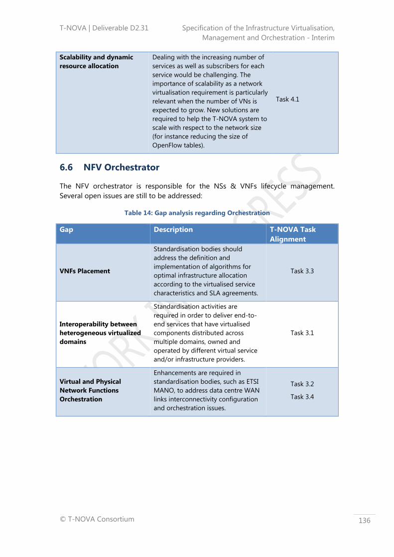
T-NOVA | Deliverable D2.31 Specification of the Infrastructure Virtualisation,
Management and Orchestration - Interim
© T-NOVA Consortium
136
Scalability and dynamic
resource allocation
Dealing with the increasing number of
services as well as subscribers for each
service would be challenging. The
importance of scalability as a network
virtualisation requirement is particularly
relevant when the number of VNs is
expected to grow. New solutions are
required to help the T-NOVA system to
scale with respect to the network size
(for instance reducing the size of
OpenFlow tables).
Task 4.1
6.6 NFV Orchestrator
The NFV orchestrator is responsible for the NSs & VNFs lifecycle management.
Several open issues are still to be addressed:
Table 14: Gap analysis regarding Orchestration
Gap Description T-NOVA Task
Alignment
VNFs Placement
Standardisation bodies should
address the definition and
implementation of algorithms for
optimal infrastructure allocation
according to the virtualised service
characteristics and SLA agreements.
Task 3.3
Interoperability between
heterogeneous virtualized
domains
Standardisation activities are
required in order to deliver end-to-
end services that have virtualised
components distributed across
multiple domains, owned and
operated by different virtual service
and/or infrastructure providers.
Task 3.1
Virtual and Physical
Network Functions
Orchestration
Enhancements are required in
standardisation bodies, such as ETSI
MANO, to address data centre WAN
links interconnectivity configuration
and orchestration issues.
Task 3.2
Task 3.4
T-NOVA | Deliverable D2.31 Specification of the Infrastructure Virtualisation,
Management and Orchestration - Interim
© T-NOVA Consortium
137
7 CONCLUSIONS
Virtualisation is a foundational technology for the T-NOVA system in particular for
the infrastructure virtualisation and management layer. Originating in the compute
domain, use of this approach now finds application in a variety of domains including
storage and networking. The approach is based on abstracting physical resources
into a form that hides its physical characteristics from either users or applications. It
brings a variety of benefits including better utilisation of resources, greater flexibility,
improved scalability, etc. Virtualisation encompasses a number of technology
approaches, at both a hardware and software level. In subsection 2.2 we reviewed the
key virtualisation methods including hypervisors, storage virtualisation,
microprocessor and I/O support for virtualisation, hardware and software network
virtualisation and accelerators. These technologies are utilised in a variety of both
commercial and open sources platforms a number of which will be utilised in the
development of the T-NOVA system. Key among these technologies are Cloud OSs,
such as OpenStack, for the provisioning and management of virtualised compute
resources that host the VNF services. We have also reviewed SDN Controllers, such as
OpenDayLight, which provision and manage the VLANs providing connectivity
between the nodes hosting VNF services and also connecting the VLANs to WANs for
inter-DC connectivity, if required by the VNF service architecture.
In the course of reviewing the various virtualisation technologies and considering
them in both the context of the telecoms service providers and the potential needs of
the T-NOVA system a variety of gaps in the capabilities of the currently available
technologies were identified; see Table 9 to Table 14. While the use of virtualisation
technologies in the IT domain is well established, adoption of this approach in carrier
grade environments to support NFV and SDN proliferation brings a unique set of
challenges that do not exist in enterprise IT environment. A variety of further
developments will be required to address specific issues in the currently available
compute, hypervisor, SDN Controller, Cloud OSs, network virtualisation and
orchestration related technologies. Where appropriate, we have mapped T-NOVA
tasks whose activities will be related to these technologies challenges or limitations. It
is expected that we will further refine these gaps to specific issues identified in
implementation of the T-NOVA system, and highlight progress that has been made in
further elucidating the characteristics of these problems, as well as the work that T-
NOVA has carried out in order to contribute towards a solution.
From an architectural point of view, the T-NOVA Orchestrator is composed by two
main building blocks: the NFVO and the VNFM.
The NFVO has two main responsibilities, which are accomplished by its two FEs
designated by NSO and VRO in the T-NOVA terminology. The NSO orchestrates the
subset of NFVO functions that are responsible for the lifecycle management of
Network Services, while the VRO performs the orchestration/management of the
virtualized infrastructure resources distributed across multiple DCs. In particular, it
performs the mapping of the incoming NS requests to the virtualized infrastructure
resources, as well as the coordination of the resources allocation and placement for

T-NOVA | Deliverable D2.31 Specification of the Infrastructure Virtualisation,
Management and Orchestration - Interim
© T-NOVA Consortium
138
each VM that composes the VNF (and the NS). The VRO does this by interacting with
a local virtualized entity, designated by VIM, as well as with the entity that interacts
with the WAN elements for connectivity management purposes, a single specialized
VIM designated by TNM.
Since the NSs are composed by VNFs and PNFs, the NFVO is able to decompose each
NS into the constituent VNFs and PNFs. Nevertheless, although the NFVO has the
knowledge of the VNFs that compose the NS, it delegates their lifecycle management
to a dedicated FE designated by VNFM.
In Section 3, the architecture for T-NOVA Orchestrator has been derived, taking into
account the working Stage 1/Stage 2 methodology, which departed from the
elaboration of a list of Orchestrator requirements identified after a research study
involving several sources, e.g. use cases defined in D2.1 (66), ETSI ISG NFV
requirements (67), ITU-T requirement for NV (10), as well as excerpts of relevant parts
of the ETSI ISG MANO WG architecture and associated FEs (8). After that Stage 1 step,
(see subsection 3.2), a Stage 2 methodology has taken place with the derivation of
the Stage 2 reference architecture and its Functional Entities, see subsection 3.3.
However, the work carried out till the moment has only produced abstracted outputs.
Stage 3 work will follow in WP3/4 where specific implementation solutions are
expected.
The T-NOVA IVM is responsible for providing the hosting and execution environment
for VNF services in the form of virtualised resources that are abstracted from the
physical resources in compute and infrastructure network domains. A system
engineering approach was adopted to define the key functional blocks in the IVM
and their interfaces. In addition the key objectives for the IVM were defined. Use of
this information and previous T-NOVA deliverables contributed to a requirement
capture process that focused on identifying the desired behaviours for the IVM.
Requirements where identified for each of the functional entities within the IVM
namely the VIM, TNM, NFV Infrastructure (compute, hypervisor, and infrastructure
network). These requirements where then used in the design of the IVM.
From an architectural perspective the T-NOVA IVM includes the key functional blocks
NFVI, VIM and TNM, which are defined and discussed in Section 4. These functional
blocks are comprised of various domains that have specific technology capabilities
required for the delivery and management of virtualised resources. For example the
NFVI is comprised of the Compute, Hypervisor and Network domains. A number of
specific interfaces provide both the internal and external connectivity that integrates
the various technology components into a functional IVM. From a T-NOVA system
perspective the key external interfaces of the IVM are those to the T-NOVA
Orchestrator, which are implemented in the VIM. These interfaces enable the T-NOVA
Orchestrator to send requests to the VIM to create and connect VMs in order to
support the deployment of VNF service and to manage the virtual resources allocated
to the VNFs in order to accomplish to SLAs. Additionally, these interfaces allow the
IVM to send infrastructure metrics related to the utilisation and performance to the T-
NOVA Orchestrator in order that this entity can perform placement decisions and
management of existing deployed services. Another important interface is the one

T-NOVA | Deliverable D2.31 Specification of the Infrastructure Virtualisation,
Management and Orchestration - Interim
© T-NOVA Consortium
139
provided by the TNM to the Orchestrator in order for it to manage the network
resources related to external networks i.e. WAN transport between DCs.
In Section 4 the overall integrated architecture of the IVM was presented together
with the architecture of the various domains that comprise the IVM with their
respective internal and external interfaces.
Collectively, these reference architectures and FEs instantiate the requirements that
were identified for the T-NOVA Orchestrator and for the T-NOVA IVM together with
its goals and objectives. The reference architectures were interrogated and validated
at functional level through the development of NS and VNF workflow diagrams as
illustrated in Section 5, which described the key actions and interactions taken within
the T-NOVA system during standard operational activities related to the deployment
and management of NS and VNF services.

T-NOVA | Deliverable D2.31 Specification of the Infrastructure Virtualisation,
Management and Orchestration - Interim
© T-NOVA Consortium
140
ANNEX A - ORCHESTRATOR REQUIREMENTS
The present annex contains a set of tables, which include the requirements identified
in Subsection 3, i.e. Orchestrator internal requirements and Interface requirements.
Each requirement has associated a set of attributes related to its identification (Req.
ID and Req. Name), to its text support (Alignment) and to its description
(Requirement Description and complementary Comments).
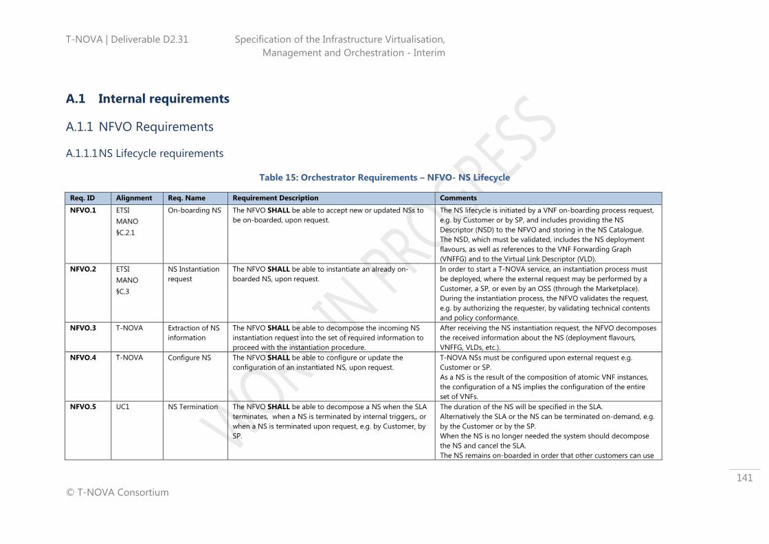
T-NOVA | Deliverable D2.31 Specification of the Infrastructure Virtualisation,
Management and Orchestration - Interim
© T-NOVA Consortium
141
A.1 Internal requirements
A.1.1 NFVO Requirements
A.1.1.1 NS Lifecycle requirements
Table 15: Orchestrator Requirements – NFVO- NS Lifecycle
Req. ID Alignment Req. Name Requirement Description Comments
NFVO.1 ETSI
MANO
§C.2.1
On-boarding NS The NFVO SHALL be able to accept new or updated NSs to
be on-boarded, upon request.
The NS lifecycle is initiated by a VNF on-boarding process request,
e.g. by Customer or by SP, and includes providing the NS
Descriptor (NSD) to the NFVO and storing in the NS Catalogue.
The NSD, which must be validated, includes the NS deployment
flavours, as well as references to the VNF Forwarding Graph
(VNFFG) and to the Virtual Link Descriptor (VLD).
NFVO.2 ETSI
MANO
§C.3
NS Instantiation
request
The NFVO SHALL be able to instantiate an already on-
boarded NS, upon request.
In order to start a T-NOVA service, an instantiation process must
be deployed, where the external request may be performed by a
Customer, a SP, or even by an OSS (through the Marketplace).
During the instantiation process, the NFVO validates the request,
e.g. by authorizing the requester, by validating technical contents
and policy conformance.
NFVO.3 T-NOVA Extraction of NS
information
The NFVO SHALL be able to decompose the incoming NS
instantiation request into the set of required information to
proceed with the instantiation procedure.
After receiving the NS instantiation request, the NFVO decomposes
the received information about the NS (deployment flavours,
VNFFG, VLDs, etc.).
NFVO.4 T-NOVA Configure NS The NFVO SHALL be able to configure or update the
configuration of an instantiated NS, upon request.
T-NOVA NSs must be configured upon external request e.g.
Customer or SP.
As a NS is the result of the composition of atomic VNF instances,
the configuration of a NS implies the configuration of the entire
set of VNFs.
NFVO.5 UC1 NS Termination The NFVO SHALL be able to decompose a NS when the SLA
terminates, when a NS is terminated by internal triggers,, or
when a NS is terminated upon request, e.g. by Customer, by
SP.
The duration of the NS will be specified in the SLA.
Alternatively the SLA or the NS can be terminated on-demand, e.g.
by the Customer or by the SP.
When the NS is no longer needed the system should decompose
the NS and cancel the SLA.
The NS remains on-boarded in order that other customers can use

T-NOVA | Deliverable D2.31 Specification of the Infrastructure Virtualisation,
Management and Orchestration - Interim
© T-NOVA Consortium
142
it.
NFVO.6 ETSI
MANO
§C.4.1
Scale-out NS The NFVO SHALL be able to scale out the NS, either upon
request or automatically.
Automatic scaling out depends on an algorithm and alternative
architecture or deployment flavours provided by the SP when
composing the NS.
Scaling out a NS might imply increasing the VMs supporting its
VNF(s).
NFVO.7 ETSI
MANO
§C.4.2
Scale-in NS The NFVO SHALL be able to scale in the NS, either upon
request or automatically.
Automatic scaling implies the use of an algorithm and alternative
architecture or deployment flavours provided by the SP when
composing the NS.
Scaling in a NS might imply decreasing the VMs supporting its
VNF(s).
A.1.1.2 VNF Lifecycle requirements
Table 16: Orchestrator Requirements – NFVO- VNF Lifecycle
Req. ID Alignment Req. Name Requirement Description Comments
NFVO.8 §B.2.1 On-boarding
VNF Package
Request
The NFVO SHALL receive new VNF packages from the NF
Store and store them in the VNF Catalogue.
VNF package includes the VNF Description (VNFD) and the VNF
software image(s).
NFVO.9 ETSI
MANO
§B.3.1.2
VNF
Instantiation
Request by the
NVFO
The NFVO SHALL be able to instantiate a VNF, upon request. When a request to instantiate a VNF is received, the NFVO
validates the request.
Optionally, the NFVO runs a feasibility check to reserve resources
before performing the actual allocation to the VIM.
The NFVO acknowledges the completion of the VNF instantiation
after configuring the VNF through the VNFM.
NFVO.10 UC2
UC3
VNF
Configuration
Request by the
NFVO
The NFVO SHALL be able to request the VNFM to configure
an instantiated VNF.
T-NOVA VNFs must be configured upon external request, e.g.
Customer or SP, or automatically upon the completion of an
instantiation process.
It includes the notification of the successful configuration.
NFVO.11 ETSI
MANO
§B.3.1.1
Check VNF
instantiation
feasibility by the
NFVO
The NFVO SHALL be able to accept and process a check
feasibility request regarding a VNF instantiation.
NFV Orchestrator receives a request to check feasibility of VNF
instantiation/scaling.
This request may come from an OSS, from commissioning of a new
VNF or VNF scaling, or as part of an order for a Network Service
instantiation/scaling.
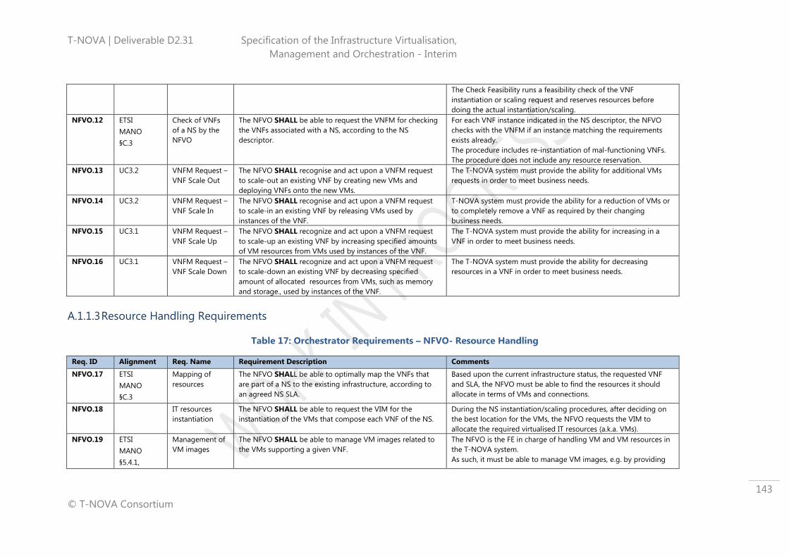
T-NOVA | Deliverable D2.31 Specification of the Infrastructure Virtualisation,
Management and Orchestration - Interim
© T-NOVA Consortium
143
The Check Feasibility runs a feasibility check of the VNF
instantiation or scaling request and reserves resources before
doing the actual instantiation/scaling.
NFVO.12 ETSI
MANO
§C.3
Check of VNFs
of a NS by the
NFVO
The NFVO SHALL be able to request the VNFM for checking
the VNFs associated with a NS, according to the NS
descriptor.
For each VNF instance indicated in the NS descriptor, the NFVO
checks with the VNFM if an instance matching the requirements
exists already.
The procedure includes re-instantiation of mal-functioning VNFs.
The procedure does not include any resource reservation.
NFVO.13 UC3.2 VNFM Request –
VNF Scale Out
The NFVO SHALL recognise and act upon a VNFM request
to scale-out an existing VNF by creating new VMs and
deploying VNFs onto the new VMs.
The T-NOVA system must provide the ability for additional VMs
requests in order to meet business needs.
NFVO.14 UC3.2 VNFM Request –
VNF Scale In
The NFVO SHALL recognise and act upon a VNFM request
to scale-in an existing VNF by releasing VMs used by
instances of the VNF.
T-NOVA system must provide the ability for a reduction of VMs or
to completely remove a VNF as required by their changing
business needs.
NFVO.15 UC3.1 VNFM Request –
VNF Scale Up
The NFVO SHALL recognize and act upon a VNFM request
to scale-up an existing VNF by increasing specified amounts
of VM resources from VMs used by instances of the VNF.
The T-NOVA system must provide the ability for increasing in a
VNF in order to meet business needs.
NFVO.16 UC3.1 VNFM Request –
VNF Scale Down
The NFVO SHALL recognize and act upon a VNFM request
to scale-down an existing VNF by decreasing specified
amount of allocated resources from VMs, such as memory
and storage., used by instances of the VNF.
The T-NOVA system must provide the ability for decreasing
resources in a VNF in order to meet business needs.
A.1.1.3 Resource Handling Requirements
Table 17: Orchestrator Requirements – NFVO- Resource Handling
Req. ID Alignment Req. Name Requirement Description Comments
NFVO.17 ETSI
MANO
§C.3
Mapping of
resources
The NFVO SHALL be able to optimally map the VNFs that
are part of a NS to the existing infrastructure, according to
an agreed NS SLA.
Based upon the current infrastructure status, the requested VNF
and SLA, the NFVO must be able to find the resources it should
allocate in terms of VMs and connections.
NFVO.18 IT resources
instantiation
The NFVO SHALL be able to request the VIM for the
instantiation of the VMs that compose each VNF of the NS.
During the NS instantiation/scaling procedures, after deciding on
the best location for the VMs, the NFVO requests the VIM to
allocate the required virtualised IT resources (a.k.a. VMs).
NFVO.19 ETSI
MANO
§5.4.1,
Management of
VM images
The NFVO SHALL be able to manage VM images related to
the VMs supporting a given VNF.
The NFVO is the FE in charge of handling VM and VM resources in
the T-NOVA system.
As such, it must be able to manage VM images, e.g. by providing

T-NOVA | Deliverable D2.31 Specification of the Infrastructure Virtualisation,
Management and Orchestration - Interim
© T-NOVA Consortium
144
§5.4.3 VIM with VM images for VNF on-boarding or updating, or by
removing images for VNF removal.
NFVO.20 UC3.1 Resources
Inventory
Tracking
The NFVO SHALL update its inventory of allocated/available
resources when resources are allocated/released.
The T-NOVA System must maintain the Infrastructure Catalogue
and accurately track resource consumption and the details of the
services consuming those resources.
A.1.1.4 Monitoring Process requirements
Table 18: Orchestrator Requirements – NFVO- Monitoring Process
Req. ID Alignment Req. Name Requirement Description Comments
NFVO.21 UC2,
UC3,
UC4
NS-specific
resource
monitoring by
the NFVO
The NFVO SHALL be able to monitor NS-related resources
on a real time basis.
NS-specific monitoring is related with the monitoring of the virtual
network links that interconnect the VNFs (retrieved from the VIM),
as well as monitoring of VNF-specific details that can be used to
assure that the NS is fulfilling the established SLA with the
customer.
NFVO.22 UC4 Monitoring
metrics
consolidation by
the NFVO
The NFVO SHALL be able to aggregate and consolidate all
monitoring metrics associated with a service.
A consolidated operational picture of the service via the dashboard
is considered a mandatory customer requirement.
The gathered metrics should be presented to the Customer, to the
SP, or to the FP, with an integrated status of the provisioned
service.
A.1.1.5 Connectivity Handling requirements
Table 19: Orchestrator Requirements – NFVO- Connectivity Handling
Req. ID Alignment Req. Name Requirement Description Comments
NFVO.23 UC1,
UC2,
UC3
NS Composition The NFVO SHALL be able to compose a NS from atomic VNF
instances and define the Forwarding Graph based on the
logical topology to interconnect the several components.
The creation of a NS from the combination of atomic/simple VNF
is important in order to simplify the process provision of NS to the
customers and avoid complex path calculations.
NFVO.24 IT Network
connectivity
instantiation
The NFVO SHALL be able to request the VIM for
instantiation and inter-connection of required VMs in the IT
compute domain.
During the NS instantiation/scaling procedures, after installing the
VMs for the VNF/NS, the NFVO requests the VIM to allocate the
required virtual IT network resources (a.k.a. IT virtual network
links).

T-NOVA | Deliverable D2.31 Specification of the Infrastructure Virtualisation,
Management and Orchestration - Interim
© T-NOVA Consortium
145
NFVO.25 ETSI
MANO
§C.3
Virtual Network
connectivity
instantiation
The NFVO SHALL be able to request the VIM for the
instantiation and inter-connection of every needed VM in the
IT network domain.
During the NS instantiation/scaling procedures, after installing the
VMs for the VNF/NS, the NFVO requests the VIM to allocate the
required virtual network resources (a.k.a. virtual network links).
NFVO.26 Legacy Network
connectivity
instantiation
The NFVO SHALL be able to request the TNM for
instantiation and inter-connection of nodes in the
infrastructure network.
During the NS instantiation/scaling procedures, after installing the
VMs for the VNF/NS, the NFVO requests the TNM to allocate the
required legacy network resources.
NFVO.27 ETSI
MANO
§C.3.6
IT network
connectivity
deletion
The NFVO SHALL be able to request the VIM the deletion of
IT network connectivity for a given NS instance and the
removal of the infrastructure allocated for a given VNF.
The T-NOVA system should able to ask the deletion of IT network
connectivity.
This requirement includes notification of the VNFM of the
removed VNF. VNFs having instances participating in NS instances
cannot be removed until the NS instance stops and is requested to
be removed. Also used in re-instantiating VNF infrastructure (e.g.,
for performance or mal-function reasons).
NFVO.28 ETSI
MANO
§C.3.6
Virtual Network
connectivity
deletion
The NFVO SHALL be able to request the VIM to delete of
virtual network connectivity for a given NS instance and to
remove the infrastructure allocated for a given VNF.
The T-NOVA system should able to ask for the deletion of virtual
network connectivity.
This requirement includes notification of the VNFM of the
removed VNF. VNFs having instances participating in NS instances
cannot be removed until the NS instance stops and is requested to
be removed. Also used in re-instantiating VNF infrastructure (e.g.,
for performance or mal-function reasons).
NFVO.29 ETSI
MANO
§C.3.6
Legacy network
connectivity
deletion
The NFVO SHALL be able to request the TNM to delete
legacy network connectivity for a given NS instance and to
remove of the infrastructure allocated for a given VNF.
The T-NOVA system should able to ask TNM for the deletion of
legacy network connectivity.
A.1.1.6 Policy Management requirements
Table 20: Orchestrator Requirements – NFVO- Policy Management
Req. ID Alignment Req. Name Requirement Description Comments
NFVO.30 UC4
ETSI
MANO
§4.5.2,
§5.4.1
Policy
enforcement
The NFVO SHALL provide the means for setting/changing
policies associated with an existing VNF.
The T-NOVA system must provide the ability for customers and
SPs to change how their VNFs behave to meet evolving business
needs, e.g. by applying new packet handling rules.

T-NOVA | Deliverable D2.31 Specification of the Infrastructure Virtualisation,
Management and Orchestration - Interim
© T-NOVA Consortium
146
A.1.1.7 Marketplace-specific interactions requirements
Table 21: Orchestrator Requirements – NFVO- Marketplace specific
Req. ID Alignment Req. Name Requirement Description Comments
NFVO.31 T-NOVA Publish NS
instantiation
The NFVO SHALL be able to notify that the requested (new,
updated) NS instantiation is ready to be used.
T-NOVA system must notify relevant external entities upon
successful instantiation of every VNF and connections between
them.
If the external entity is the Marketplace, it may use this notification
for Accounting/Billing purposes.
NFVO.32 T-NOVA Publish NS
metrics
The NFVO SHALL be able to publish the NS metrics, if
allowed by SLA.
The T-NOVA system must provide to external entities NS metrics in
order to enable service control.
NFVO.33 UC1.1 NFV mapping of
SLA data
The NFVO SHALL map the SLA related data to NFV
attributes.
Results of selection offerings materialized in SLAs need to be
translated into NFV attributes in order to be processed by the T-
NOVA system, according to the contents of the VNF descriptor
where the amount of needed resources is indicated.
NFVO.34 T-NOVA SLA
enforcement
request
The NFVO SHALL be able to take the required actions (e.g.
scale out, new instantiation) upon request to enforce a SLA.
It is assumed that the SLA provides all the information about
metrics and thresholds to be compared with, together with the NS
descriptor providing alternative architectures or deployment
flavours, e.g. scaling in when metrics show under-used resources
should be automatic.
NFVO.35 UC4,
UC5
NS usage
accounting and
billing
The NFVO SHALL store all the information about resources
usage per service, and SHALL provide it to external entities
to bill on a pay-per-use mode.
Pay-as-you-go may be considered attractive for some Customers,
as an option, as opposed to flat-rate.
The NFVO should notify relevant FEs in order that the T-NOVA
system becomes able to deploy this type of billing/charging.

T-NOVA | Deliverable D2.31 Specification of the Infrastructure Virtualisation,
Management and Orchestration - Interim
© T-NOVA Consortium
147
A.1.2 VNFM Requirements
A.1.2.1 VNF Lifecycle requirements
Table 22: Orchestrator Requirements – VNFM- VNF Lifecycle
Req. ID Alignment Req. Name Requirement Description Comments
VNFM.1 ETSI
MANO
§B.3.1.2
VNF
Instantiation
Request by the
VNFM
The VNFM SHALL be able to accept a request from the
NFVO to instantiate a VNF.
After receiving a VNF instantiation request from the NFVO, the
VNFM will start coordinating the VNF instantiation procedure.
Nevertheless, the virtualized resources allocation is under the
scope of the NFVO and therefore the VNFM will have to request
the later to allocate the required resources for the VNF.
VNFM.2 UC2
UC3
VNF
Configuration
Request by the
VNFM
The VNFM SHALL be able to accept a NFVO request to
configure an instantiated VNF.
T-NOVA VNFs must be configured upon external request or
following an external instantiation request.
It includes the notification of the successful configuration.
VNFM.3 ETSI
MANO
§B.3.1.1
Check VNF
instantiation
feasibility by the
VNFM
The VNFM SHALL be able to accept requests coming from
the NFVO and process a check feasibility procedure
regarding a VNF instantiation.
The VNFM receives a request to check feasibility of a VNF
instantiation/scaling and processes the VNF descriptor after
validating the request.
VNFM.4 ETSI
MANO
§C.3
Check of VNFs
part of a NS by
the VNFM
The VNFM SHALL be able to accept a request from the
NFVO to check the VNFs associated with a NS, according to
the NS descriptor.
For each VNF instance indicated in the NS descriptor, the VNFM
checks if a VNF instance matching the requirements already exists.
Includes re-instantiation request of mal-functioning VNFs..
VNFM.5 UC2 VNF lifecycle
automation by
the VNFM
The VNFM SHALL be able to automate the instantiation of
VNFs and associated VM resources by triggering scaling
procedures.
Automation of VNF lifecycle is an essential characteristic of the T-
NOVA system.
Triggering of scaling procedures is based on the monitoring
process maintained over VNFs, as well as on policy management
and other internal algorithm criteria.
VNFM.6 UC3.2 Auto VNF Scale
Out
The VNFM SHALL provide the means to automatically scale-
Out a VNF.
T-NOVA system needs to automatically scale-out a VNF to meet
SLAs in an efficient and timely manner.
VNFM.7 UC3.2,
UC4
Auto VNF Scale
In
The VNFM SHALL provide the means to automatically scale-
In an existing VNF.
T-NOVA system needs to automatically scale-in a VNF to meet
SLAs in an efficient and timely manner.
VNFM.8 UC3.1 Auto VNF Scale
Up
The VNFM SHALL provide the means to automatically scale-
Up an existing VNF.
This procedure ensures that resources are consumed in an efficient
manner and SLA specified targets on resource consumption are
met.

T-NOVA | Deliverable D2.31 Specification of the Infrastructure Virtualisation,
Management and Orchestration - Interim
© T-NOVA Consortium
148
VNFM.9 UC3.1 Auto VNF Scale
Down
The VNFM SHALL provide the means to automatically scale-
Down a VNF.
This procedure ensures that resources are consumed in an efficient
manner and SLA specified targets on resource consumption are
met.
A.1.2.2 Monitoring Process requirements
Table 23: Orchestrator requirements – VNFM- Monitoring Process
Req. ID Alignment Req. Name Requirement Description Comments
VNFM.10 UC2,
UC3,
UC4
VNF-specific
resource
monitoring by
the VNFM
The VNFM SHALL be able to monitor VNF-related resources
on a real time basis.
VNF-specific monitoring is related with the monitoring of
information retrieved from the VIM, related to the virtualized
infrastructure resources allocated to the VNF (i.e.
compute/storage/memory of the VMs and virtual network links
that interconnect the VMs), as well as monitoring of VNF-specific
metrics that can be used to assure that the VNF is behaving as it
should.
VNFM.11 UC4 Monitoring
metrics
consolidation by
the VNFM
The VNFM SHALL be able to aggregate and consolidate all
monitoring VNF metrics associated with a service.
A consolidated operational picture of the service via the dashboard
is considered a mandatory customer requirement.
The collected metrics should be presented by the VNFM to the
NVFO, and from this FE to the dashboard with an integrated status
of the provisioned service.

T-NOVA | Deliverable D2.31 Specification of the Infrastructure Virtualisation,
Management and Orchestration - Interim
© T-NOVA Consortium
149
A.2 Interface requirements
A.2.1 Interface with VIM
The requirements identified for the Interface with the VIM module are as follows:
Table 24: Requirements between the Orchestrator and VIM
Req. id Alignment Domain(s) Requirement
Name
Requirement Description Justification of Requirement
Or-Vi.01 Orchestrator,
VIM
Reserve / release
resources
The Orchestrator SHALL use this interface
to request the VIM to reserve or release
the entire required infrastructure needed
for a given VNF
Care must be taken in order not to have resources
allocated for long periods of time, thus impacting on the
optimisation of resource usage.
Or-Vi.02
T_NOVA_03,
T_NOVA_21,
T_NOVA_22,
T_NOVA_26,
T_NOVA_31,
T_NOVA_33,
T_NOVA_34,
T_NOVA_36,
T_NOVA_37,
T_NOVA_38,
T_NOVA_39,
T_NOVA_40,
T_NOVA_42,
T_NOVA_43,
T_NOVA_44,
T_NOVA_45,
T_NOVA_58 4
Orchestrator,
VIM
Allocate / release /
update resources
The Orchestrator SHALL use this interface
to request the VIM to allocate, update or
release the required infrastructure needed
for a given VNF
It is assumed that configuration information is a resource
update. Resource update might imply stop and re-start,
with a migration in between.
4 Refers to T-NOVA requirements described in deliverable D2.1 (63)

T-NOVA | Deliverable D2.31 Specification of the Infrastructure Virtualisation,
Management and Orchestration - Interim
© T-NOVA Consortium
150
Or-Vi.03 Orchestrator,
VIM
Add / update /
delete
SW image
The Orchestrator SHALL use this interface
to add, update or delete a SW image
(usually for a VNF Component)
Performance will probably demand having these images
ready to be deployed on the Orchestrator’s side
Or-Vi.04 UC4,
T_NOVA_46 Orchestrator,
VIM
Retrieve
infrastructure
usage data
The Orchestrator SHALL use this interface
to collect infrastructure utilisation data
(network, compute and storage) from the
VIM
Some of this data is used to determine the performance
of the infrastructure (including failure notifications) and
to inform decisions on where to provision newly
requested services or to where to migrate an already
provisioned NS that is predicted to break its SLA. This
interface will very likely have to support very high
volume traffic.
Or-Vi.05 UC4,
T_NOVA_20 Orchestrator,
VIM
Retrieve
infrastructure
resources
metadata
The Orchestrator SHALL use this interface
to request infrastructure's metadata from
the VIM
Due to high performance needs, this metadata will most
probably have to be cached on the Orchestrator’s side
Or-Vi.06
T_NOVA_24,
T_NOVA_25,
T_NOVA_35,
T_NOVA_27
Orchestrator,
VIM
Manage
VM’s
state
The Orchestrator SHALL use this interface
to request the VIM to manage the VMs
allocated to a given VNF.
We can assume a finite and small number of possible VM
states, e.g., ‘Being configured’, ‘Not running’, ‘Running’,
‘Being re-scaled’, ‘Being stopped’. It is assumed that
when in a ‘Running’ state the VM is ready to be (re-)
configured.
Or-Vi.07 T_NOVA_02 Orchestrator,
VIM Secure interfaces
The interfaces between the Orchestrator
and the VIM SHALL be secure, in order to
avoid eavesdropping (and other security
threats)
We should keep in mind that encrypting all the
communication between these two entities will probably
make a performing solution too costly

T-NOVA | Deliverable D2.31 Specification of the Infrastructure Virtualisation,
Management and Orchestration - Interim
© T-NOVA Consortium
151
A.2.2 Interface with VNF
The requirements identified for the Interface with the VNF module are as follows:
Table 25: Requirements between the Orchestrator and VNF
Req. id Alignment Domain(s) Requirement
Name
Requirement Description Justification of Requirement
Vnfm-
Vnf.01 T_NOVA_02 VNFM, VNF Secure interfaces
All the interfaces between the VNFM and
the VNF SHALL be secure, in order to avoid
eavesdropping (and other security threats)
Required to avoid eavesdropping the connection
between the VNFM and each VNF. We should keep in
mind that encrypting all the communication between
these two entities will probably make a high
performance solution too costly
Vnfm-
Vnf.02 VNFM, VNF
Instantiate/termin
ate VNF
The VNFM SHALL use this interface to
instantiate a new VNF or terminate one that
has already been instantiated
Required to create/remove VNFs during the VNF lifecycle
Vnfm-
Vnf.03
T_NOVA_46,
T_NOVA_48 VNFM, VNF
Retrieve VNF
instance run-time
information
The VNFM SHALL use this interface to
retrieve the VNF instance run-time
information (including performance metrics)
VNF instance run-time information is crucial both for
automating VNF scaling and for showing Network
Services’ metrics in the Marketplace’s Dashboard
Vnfm-
Vnf.04
T_NOVA_23
T_NOVA_33 VNFM, VNF Configure a VNF
The VNFM SHALL use this interface to (re-
)configure a VNF instance
In the general case, the Customer should be able to (re-
)configure a VNF (instance). Includes scaling.
Vnfm-
Vnf.05
T_NOVA_24,
T_NOVA_35,
T_NOVA_58
VNFM, VNF Manage VNF state
The VNFM SHALL use this interface to
collect/request from the NFS the
state/change of a given VNF (e.g. start, stop,
etc.)
This interface includes collecting the state of the VNF (as
well as changing it). The VNF instance should include a
state like ‘Ready to be used’ when it is registered in the
repository.
Vnfm-
Vnf.06
T_NOVA_36,
T_NOVA_37,
T_NOVA_38,
T_NOVA_39,
T_NOVA_42,
T_NOVA_43,
T_NOVA_44,
T_NOVA_45
VNFM, VNF Scale VNF
The VNFM SHALL use this interface to
request the appropriate scaling
(in/out/up/down) metadata to the VNF
VNF scaling depends on the (mostly architectural)
options the FP provided when registering the VNF. The
VNF scaling metadata is then used by the NFVO to
request the VIM to allocate the required infrastructure

T-NOVA | Deliverable D2.31 Specification of the Infrastructure Virtualisation,
Management and Orchestration - Interim
© T-NOVA Consortium
152
A.2.3 Interface with Marketplace
The requirements identified for the Interface with the Marketplace are as follows:
Table 26: Requirements between the Orchestrator and the Marketplace
Req. id Alignment Domain Requirement
Name
Requirement Description Justification of Requirement
NFVO-
MKT.01
UC1,
T_NOVA_10,
T_NOVA_15
Orchestrator,
Marketplace
Provide
available VNFs
The Marketplace SHALL use this interface
with the Orchestrator to provide the Service
Provider with a list of the VNFs, so that it can
select and parameterise them, or use them in
the composition of a new network service.
It is assumed that this VNF metadata includes a
URL/repository name from which to fetch the actual VNF
software and install it on the previously allocated
infrastructure (see NFVO.10 below). Note that, although
this information will most certainly have to be cached on
the Orchestrator’s side for performance reasons, the
available VNFs will be dynamic, so updates to this
cached information will be rather frequent.
NFVO-
MKT.02
UC2,
T_NOVA_04,
T_NOVA_08,
T_NOVA_20
Orchestrator,
Marketplace
Provision a
new network
service
The Marketplace SHALL use this interface to
inform the Orchestrator to provision the
network service, after the Customer has
selected and parameterised the network
service. The Orchestrator SHALL read the SLA
and the date/time to start the new network
service. Each NS can be composed of one or
more VNFs.
The date/time of start/end the service are part of the
SLA.
NFVO-
MKT.03
UC3,
T_NOVA_31,
T_NOVA_32,
T_NOVA_33,
T_NOVA_36,
T_NOVA_42,
T_NOVA_44
Orchestrator,
Marketplace
Change
configuration
of a deployed
network
service
The Marketplace SHALL use this interface to
change the configuration of an already
provisioned network service on the
Orchestrator.
It is assumed that information about scaling
(up/down/in/out) is included in the SLA (or at least
reasonable values can be inferred).
NFVO-
MKT.04
UC5,
T_NOVA_28,
T_NOVA_29,
T_NOVA_34,
Orchestrator,
Marketplace
Provide
network
service state
transitions
The Marketplace SHALL use this interface to
determine the state transitions of a given
network service, e.g. to facilitate starting and
stopping billing for the service.
It is assumed that each NS has a pre-defined state-
diagram, like ‘Ready to run’, ‘Running’, ‘Stopped’, etc.,
that is also known to the Marketplace.

T-NOVA | Deliverable D2.31 Specification of the Infrastructure Virtualisation,
Management and Orchestration - Interim
© T-NOVA Consortium
153
T_NOVA_41,
T_NOVA_48,
T_NOVA_56,
T_NOVA_57
NFVO-
MKT.05
UC4,
T_NOVA_28,
T_NOVA_29,
T_NOVA_30,
T_NOVA_46,
T_NOVA_52
Orchestrator,
Marketplace
Provide
network
service
monitoring
data
The Marketplace SHALL use this interface to
show the Customer how the subscribed
network service is behaving, how it compares
to the agreed SLA and bill the service usage.
This interface will very likely have to support very high
volume traffic.
NFVO-
MKT.11
UC6,
T_NOVA_03,
T_NOVA_58
Orchestrator,
Marketplace
Terminate a
provisioned
NS
The Marketplace SHALL use this interface to
request the Orchestrator to terminate
provisioned NSs
It is assumed that the impact on the dependent modules
like billing, are taken care by the Marketplace (see
NFVO.04). SLA Management is part of the Marketplace.
Either after a customer’s request or by the pre-defined
ending date had been attained, the SLA Management
notifies the Orchestrator of the end of the SLA.
NFVO-
MKT.12 T_NOVA_02 Orchestrator,
Marketplace
Secure
communicatio
n
Interfaces between the Marketplace and the
Orchestrator SHOULD be secured.
Encryption should be used, in order to prevent
eavesdropping. Even between the Marketplace and the
Orchestrator, since the Marketplace is really a set of
distributed apps.

T-NOVA | Deliverable D2.31 Specification of the Infrastructure Virtualisation,
Management and Orchestration - Interim
© T-NOVA Consortium
154
ANNEX B - VIRTUALISED INFRASTRUCTURE MANAGEMENT REQUIREMENTS
B.1 Virtual Infrastructure Management Requirements
Table 27: IVM Requirements - VIM
Req. id T-NOVA Use
Case
Alignment
Domain Requirement Name Requirement Description Justification of Requirement
VIM.1 UC1, UC2.1 VIM Ability to handle
heterogeneous physical
resources
The T-NOVA VIM SHALL have the ability to
handle and control both IT and network
physical infrastructure resources.
Basic functional requirement of the VIM.
VIM.2 UC1, UC2.1 VIM Ability to provision
virtual instances of the
infrastructure resources
The T-NOVA VIM SHALL be able to create
virtual resource instances from physical
infrastructure resources upon request
Required to support VIM integration with
the T-NOVA Orchestrator.
VIM.3 UC3/3.1/3.2 VIM API Exposure The T-NOVA VIM SHALL provide a set of API’s
to support integration with its control
functions with the T-NOVA Orchestration layer.
Required to support VIM integration with
the T-NOVA Orchestrator
VIM.4 UC2.1 VIM Resource abstraction The T-NOVA IVM system SHALL provide
resource abstraction at the VIM level for
representation of physical resources.
Required to support VIM integration with
the T-NOVA Orchestrator.
VIM.5 UC1.1 UC1.3
UC2.1 UC4
VIM Ability to support
different service levels
The VIM network controller SHOULD provide
the ability to request different service levels
with measurable reliability and availability
metrics.
Required to supported SLA’s agreement
when purchasing a VNF service in the T-
NOVA Marketplace
VIM.6 UC3.1, UC3.2 VIM Live VM and link
migration
The VIM network controller SHOULD support
live VM migration within a data centre and
between data centres including migration of
virtual links without traffic disruption
This capability is required for a number of
operational reasons such as service
optimisation, SLA management, service
resilience etc.

T-NOVA | Deliverable D2.31 Specification of the Infrastructure Virtualisation,
Management and Orchestration - Interim
© T-NOVA Consortium
155
VIM.7 UC1 VIM Translation of references
between logical and
physical resource
identifiers
The VIM network controller SHOULD be able
to assign IDs to virtual components (e.g., NFs,
virtual links) and provide the translation of
references between logical and physical
resource identifiers.
Need to track the use of physical network
resources.
VIM.8 UC2
UC3
VIM Isolated virtual networks
sharing the same
physical infrastructure
The VIM network controller SHALL guarantee
isolation among the different virtual network
resources created to provision the requested
services through the marketplace.
T-NOVA system will be providing services
for different customers through the
composition and deployment of VNFs.
Those services will share the same
physical network infrastructure, at the
same time they belong to different
customers. Thus, isolation at the physical
level must be guaranteed for each
customer.
VIM.9 UC3.1, UC3.2,
UC3.3 UC4
VIM Control and Monitoring The VIM network controller SHALL be able to
visualise the real-time status and the history
reports related to the performance and
resource utilisation of both the physical
network infrastructure and multiple instances
of virtual networks running over it.
T-NOVA must be able to visualise the
real-time status and the history reports
related to the performance and the
resource utilisation of both the physical
infrastructure and the multiple instances
of virtual networks running over it.
VIM.10 UC3 VIM Scalability The VIM network controller SHOULD scale in
accordance to the number of virtual resource
instances and physical network domains
The T-NOVA system should be able to
manage a large network infrastructure.
VIM.11 UC1 VIM Network service and
resource discovery
The VIM network controller SHOULD provide
mechanisms to discover physical network
resources.
The Orchestrator must be aware of the
available physical network resources.
VIM.12 UC1.1
UC2.1
UC3.1
UC3.2
UC3.3
UC4
VIM Specification of
performance parameters
The VIM network controller SHOULD allow the
infrastructure connectivity services to specify
the following performance related parameters:
Maximum overhead (bits required
for the network virtualisation
technique, per packet or percentage
of traffic)
Maximum delay
Maximum delay variation
T-NOVA system should support a high
level of customisation for the network
service.
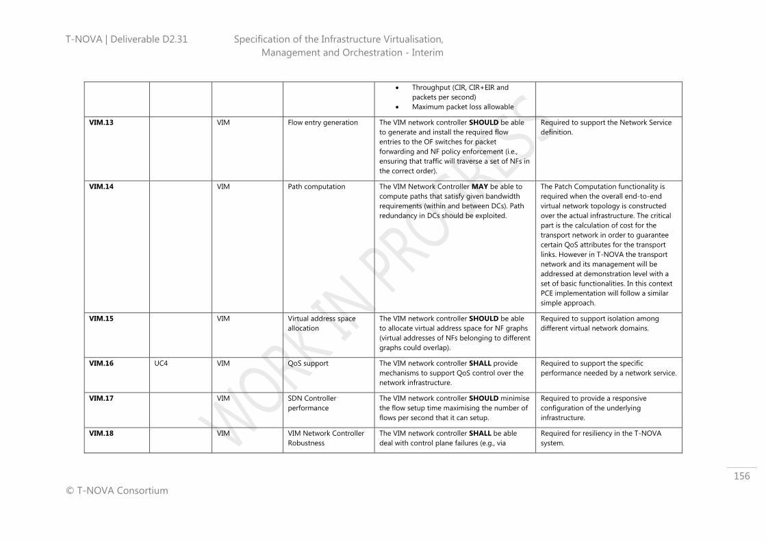
T-NOVA | Deliverable D2.31 Specification of the Infrastructure Virtualisation,
Management and Orchestration - Interim
© T-NOVA Consortium
156
Throughput (CIR, CIR+EIR and
packets per second)
Maximum packet loss allowable
VIM.13 VIM Flow entry generation The VIM network controller SHOULD be able
to generate and install the required flow
entries to the OF switches for packet
forwarding and NF policy enforcement (i.e.,
ensuring that traffic will traverse a set of NFs in
the correct order).
Required to support the Network Service
definition.
VIM.14 VIM Path computation The VIM Network Controller MAY be able to
compute paths that satisfy given bandwidth
requirements (within and between DCs). Path
redundancy in DCs should be exploited.
The Patch Computation functionality is
required when the overall end-to-end
virtual network topology is constructed
over the actual infrastructure. The critical
part is the calculation of cost for the
transport network in order to guarantee
certain QoS attributes for the transport
links. However in T-NOVA the transport
network and its management will be
addressed at demonstration level with a
set of basic functionalities. In this context
PCE implementation will follow a similar
simple approach.
VIM.15 VIM Virtual address space
allocation
The VIM network controller SHOULD be able
to allocate virtual address space for NF graphs
(virtual addresses of NFs belonging to different
graphs could overlap).
Required to support isolation among
different virtual network domains.
VIM.16 UC4 VIM QoS support The VIM network controller SHALL provide
mechanisms to support QoS control over the
network infrastructure.
Required to support the specific
performance needed by a network service.
VIM.17 VIM SDN Controller
performance
The VIM network controller SHOULD minimise
the flow setup time maximising the number of
flows per second that it can setup.
Required to provide a responsive
configuration of the underlying
infrastructure.
VIM.18 VIM VIM Network Controller
Robustness
The VIM network controller SHALL be able
deal with control plane failures (e.g., via
Required for resiliency in the T-NOVA
system.

T-NOVA | Deliverable D2.31 Specification of the Infrastructure Virtualisation,
Management and Orchestration - Interim
© T-NOVA Consortium
157
redundancy) in a robust manner.
VIM.19 VIM Hypervisor Abstraction
and API
The VIM Hypervisor Controller SHALL abstract
a basic subset of hypervisor commands in a
unified interface and in a Plug-In fashion. This
includes commands like start, stop, reboot etc.
Different Hypervisors have various
advantages such as full hardware
emulation or paravirtualization. In order to
get the best functionality and the best
performance for a VM, different
Hypervisors must be supported.
VIM.20 VIM Query API and
Monitoring
The VIM Hypervisor Controller SHALL have a
Query API that allows other T-NOVA
components to retrieve metrics, configuration
and used hypervisor technology per compute
node.
The orchestrator must be able to make
the best decision regarding performance,
functionality and a SLA for the creation of
VMs. The orchestrator requires
information from the hypervisor and the
compute infrastructure under its control
to make placement and management
decisions.
VIM.21 VIM VM Placement Filters The VIM Compute Controller SHALL offer a set
of filters that are appropriate to VNF
deployments to achieve a more granular
placement strategy with a scheduler.
Some requirements set by the
orchestrator do need a more specific
placement of the VM. E.g. a CPU core filter
can be applied to the scheduler so that
the VM is only placed on a compute node,
if more than 3 CPU cores are available.
VIM.22 VIM Base-Image Repository
integration
The VIM Compute Controller SHALL have an
integration-module to interact directly with the
non-configured VM images that need to be
deployed.
The compute controller must have access
to the repository with the basic VM
images. Those base images will be
deployed in the desired flavour by the
orchestrator regarding configuration, disk
space, CPU and memory.
VIM.23 UC2 VIM Hardware Information
Collection
The VIM Compute Controller SHALL be able to
receive physical hardware information and
provide this information via an API to the
orchestrator.
In order to operate efficient high level NF
like deep packet inspection, specific
capabilities need to available on the CPU
or in the form of co-processor cards.. This
module can retrieve such information
automatically and provide it to the
orchestrator for intelligent decisions.

T-NOVA | Deliverable D2.31 Specification of the Infrastructure Virtualisation,
Management and Orchestration - Interim
© T-NOVA Consortium
158
VIM.24 UC4 VIM Virtualised Infrastructure
Metrics
The VIM SHALL collected performance and
utilisation metrics from the virtualised
resources in the NFVI and report this data in
raw or processed formats via a northbound
interface to the Orchestrator.
The Orchestrator needs data to make
scaling decisions on VNF service based on
SLA criteria.
B.2 Transport Network Management Requirements
Table 28: IVM Requirements - TNM
Req. id T-NOVA Use
Case
Alignment
Domain Requirement Name Requirement Description Justification of Requirement
TN.1 Transport Network
Management
Legacy (non-SDN)
Network Management
The IVM SHOULD be extensible in order to
support interaction with WAN network devices
via a Network Infrastructure Manager.
It is assumed that any legacy network
technology used for the realisation of
transport network links interconnecting
NFVI-PoPs is managed through this
Network Management system. The
implementation is out T-NOVA scope.
TN.2 UC1.1, UC2.1,
UC3.1, UC3.2,
UC3.3, UC4
Transport Network
Management
Specification of
performance parameters
The network SHOULD allow the provisioning
of network services according to the following
performance related parameters:
Maximum overhead (bits required
for the network virtualisation
technique, per packet or percentage
of traffic)
Maximum delay
Maximum delay variation (jitter)
Throughput (CIR, CIR+EIR and
packets per second)
Maximum packet loss allowed
QoS level
Failover/Resiliency
Some or all of these parameters will be
taken into account when configuring and
provisioning transport network links.
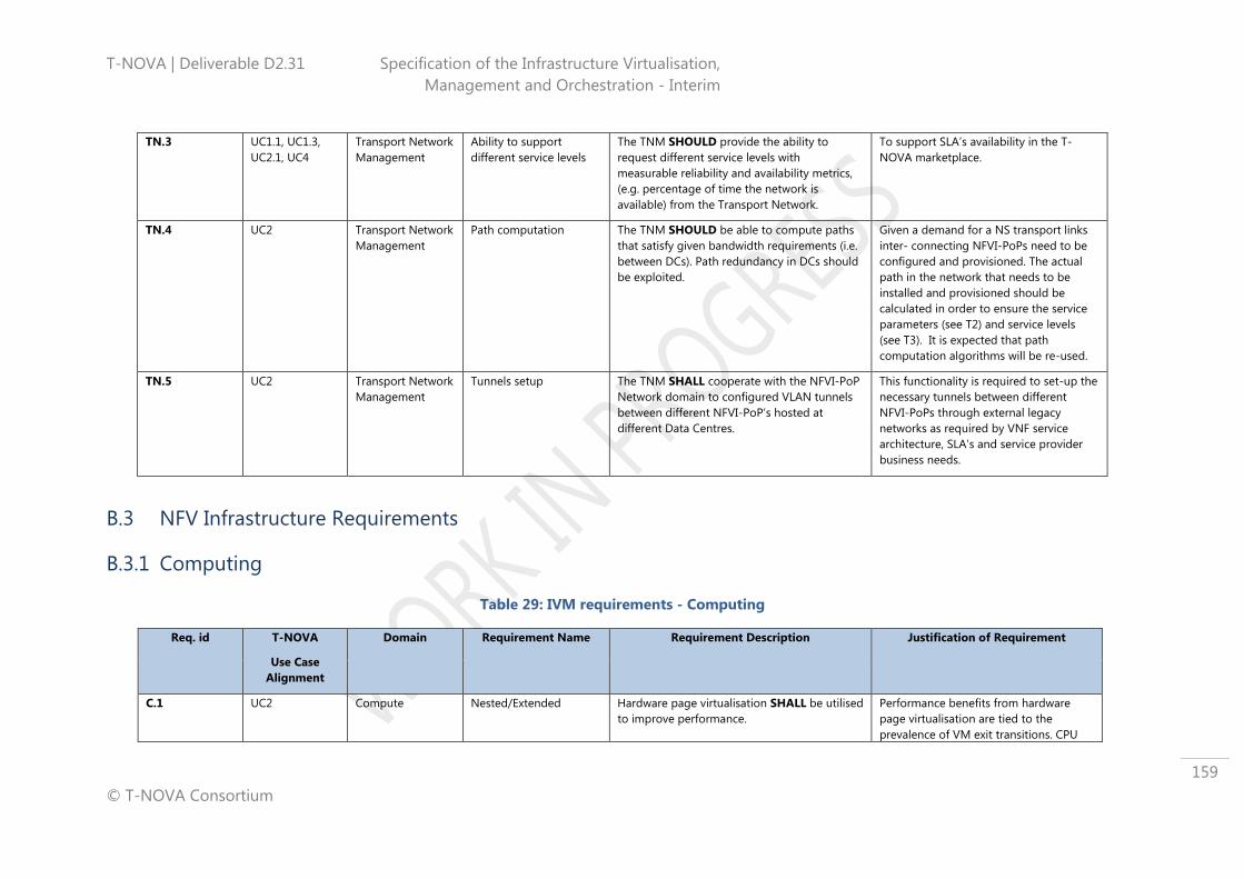
T-NOVA | Deliverable D2.31 Specification of the Infrastructure Virtualisation,
Management and Orchestration - Interim
© T-NOVA Consortium
159
TN.3 UC1.1, UC1.3,
UC2.1, UC4
Transport Network
Management
Ability to support
different service levels
The TNM SHOULD provide the ability to
request different service levels with
measurable reliability and availability metrics,
(e.g. percentage of time the network is
available) from the Transport Network.
To support SLA’s availability in the T-
NOVA marketplace.
TN.4 UC2 Transport Network
Management
Path computation The TNM SHOULD be able to compute paths
that satisfy given bandwidth requirements (i.e.
between DCs). Path redundancy in DCs should
be exploited.
Given a demand for a NS transport links
inter- connecting NFVI-PoPs need to be
configured and provisioned. The actual
path in the network that needs to be
installed and provisioned should be
calculated in order to ensure the service
parameters (see T2) and service levels
(see T3). It is expected that path
computation algorithms will be re-used.
TN.5 UC2 Transport Network
Management
Tunnels setup The TNM SHALL cooperate with the NFVI-PoP
Network domain to configured VLAN tunnels
between different NFVI-PoP’s hosted at
different Data Centres.
This functionality is required to set-up the
necessary tunnels between different
NFVI-PoPs through external legacy
networks as required by VNF service
architecture, SLA’s and service provider
business needs.
B.3 NFV Infrastructure Requirements
B.3.1 Computing
Table 29: IVM requirements - Computing
Req. id T-NOVA
Use Case
Alignment
Domain Requirement Name Requirement Description Justification of Requirement
C.1 UC2 Compute Nested/Extended Hardware page virtualisation SHALL be utilised
to improve performance.
Performance benefits from hardware
page virtualisation are tied to the
prevalence of VM exit transitions. CPU

T-NOVA | Deliverable D2.31 Specification of the Infrastructure Virtualisation,
Management and Orchestration - Interim
© T-NOVA Consortium
160
should have large TLBs
C.2 UC2, UC3 Compute Central Storage A central storage subsystem (SAN) SHALL be
available in order to enable advanced
functionalities like VM migration and server
clustering
Required to support use cases 3/3.1/3.2.
Also required for system resilience.
C.3 UC4 Compute No SPOF All hardware components SHALL be deployed
with proper redundancy mechanisms (e.g.
redundant SAN switches and network
switches) in order to avoid single points of
failure
Required to support use cases 3/3.1/3.2.
Also required for system resilience.
C.4 UC4.1 Compute Performance All hardware components SHALL satisfy
specific performance parameters (e.g. IOPS
and R/W operation ratio in case of storage
resources) in order to provide required
performance levels
Required to guarantee proper SLAs
C.5 UC2 Compute Hypervisor compatibility Servers and storage SHOULD be compatible
with the chosen hypervisor(s)
Required to ensure basic system
functionality and reliability.
C.6 UC2, UC3 Compute Central Storage -
efficiency
Central storage SHALL support functionalities
like Automatic Storage Tiering (AST), thin
provisioning and deduplication, in order to
reduce costs, improve efficiency and
performance
Required to support SLA’s associated
with VNF services.
C.7 UC4 Compute Compute Domain
Metrics
The compute domain SHALL provide metrics
and statistics relating to the capacity, capability
and utilisation of hardware resources:
• CPU cores
• Memory
• IO (including accelerators)
• Storage subsystem
These metric shall include both static and
dynamic metrics
This information is required at the
Orchestration layer to make decisions
about the placement of new VNF,
services, to manage existing services to
ensure SLA compliance and to ensure
reliable of the system.
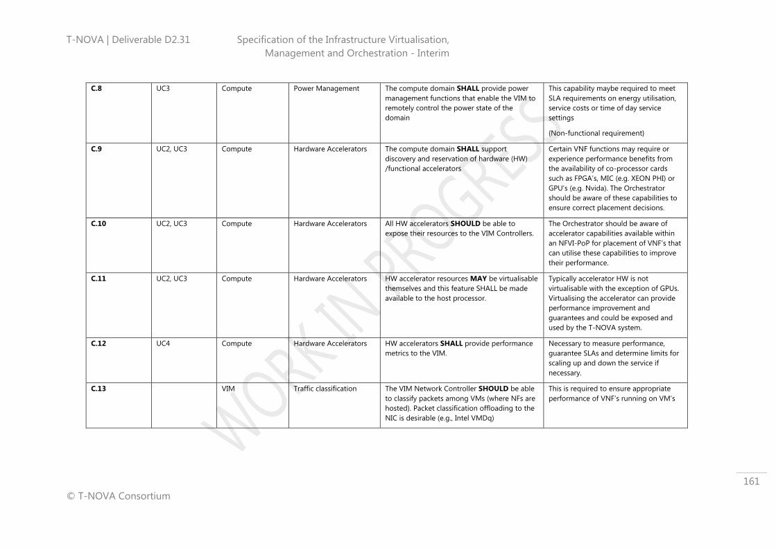
T-NOVA | Deliverable D2.31 Specification of the Infrastructure Virtualisation,
Management and Orchestration - Interim
© T-NOVA Consortium
161
C.8 UC3 Compute Power Management The compute domain SHALL provide power
management functions that enable the VIM to
remotely control the power state of the
domain
This capability maybe required to meet
SLA requirements on energy utilisation,
service costs or time of day service
settings
{Non-functional requirement}
C.9 UC2, UC3 Compute Hardware Accelerators The compute domain SHALL support
discovery and reservation of hardware (HW)
/functional accelerators
Certain VNF functions may require or
experience performance benefits from
the availability of co-processor cards
such as FPGA’s, MIC (e.g. XEON PHI) or
GPU’s (e.g. Nvida). The Orchestrator
should be aware of these capabilities to
ensure correct placement decisions.
C.10 UC2, UC3 Compute Hardware Accelerators All HW accelerators SHOULD be able to
expose their resources to the VIM Controllers.
The Orchestrator should be aware of
accelerator capabilities available within
an NFVI-PoP for placement of VNF’s that
can utilise these capabilities to improve
their performance.
C.11 UC2, UC3 Compute Hardware Accelerators HW accelerator resources MAY be virtualisable
themselves and this feature SHALL be made
available to the host processor.
Typically accelerator HW is not
virtualisable with the exception of GPUs.
Virtualising the accelerator can provide
performance improvement and
guarantees and could be exposed and
used by the T-NOVA system.
C.12 UC4 Compute Hardware Accelerators HW accelerators SHALL provide performance
metrics to the VIM.
Necessary to measure performance,
guarantee SLAs and determine limits for
scaling up and down the service if
necessary.
C.13 VIM Traffic classification The VIM Network Controller SHOULD be able
to classify packets among VMs (where NFs are
hosted). Packet classification offloading to the
NIC is desirable (e.g., Intel VMDq)
This is required to ensure appropriate
performance of VNF’s running on VM’s

T-NOVA | Deliverable D2.31 Specification of the Infrastructure Virtualisation,
Management and Orchestration - Interim
© T-NOVA Consortium
162
B.3.2 Hypervisor
Table 30: IVM Requirements - Hypervisor
Req. id T-NOVA
Use Case
Alignment
Domain Requirement Name Requirement Description Justification of Requirement
H.1 UC3
UC4
Hypervisor Compute Domain
Metrics
The Hypervisor SHALL gather all relevant
metrics and resource status information
required by the Orchestrator from the
compute domain and will provide the data to
the VIM via a VIM-Hypervisor interface
The Orchestrator requires the
information from the compute domain
to make decisions regard the placement
of new VNF services to adjusting existing
services to maintain SLA’s
H.2 UC3,
UC4
Hypervisor Network Domain Metrics The hypervisor SHALL gather all relevant
metrics (e.g. bandwidth requirements) from
the infrastructure networking domain and
provide data to the VIM via a VIM-Hypervisor
interface
The Orchestrator requires the
information from the next work domain
to make decisions regard the placement
of new VNF services to adjusting existing
services to maintain SLA’s
H.3 UC3 Hypervisor VM Portability The T-NOVA hypervisor SHALL be able to
unbind the VM from the hardware in order to
allow the VM to be migrated to a different
physical resource.
Required to ensure that VNF are fully
portable in the T-NOVA systems for
support various conditions such as
scaling, resilience, maintenance etc.
H.4 UC3 Hypervisor VM Migration -
Notification
The T-NOVA hypervisor SHALL support
instructions to provision, migrate, rescale,
delete etc. a VM received via a Hypervisor-VIM
interface
Fundamental requirement for the T-
NOVA system to function
H.5 UC3 Hypervisor Predictive VM Migration
Performance
The hypervisor SHALL provide metrics to allow
the VIM and Orchestrator to make predictions
as to the impact of migration.
This capability is required to ensure that
any infrastructure management actions
such as consolidation will not impact on
VNF service performance
H.6 UC2 Hypervisor Performance Impact The hypervisor SHALL have minimal impact on
VNF workload performance
Require to ensure that the performance
of the hosted VNF is not impacted.

T-NOVA | Deliverable D2.31 Specification of the Infrastructure Virtualisation,
Management and Orchestration - Interim
© T-NOVA Consortium
163
H.7 UC2
UC3
Hypervisor Platform Features
Awareness/Exposure
The hypervisor SHALL be able to discover the
existence of features and functionality
provided by resources such as the compute,
accelerators, storage and networking and to
expose these features to the Orchestrator via
the VIM.
Enhanced platform awareness by the
Hypervisor and making this information
available to the Orchestrator will allow
the Orchestrator to make more
intelligent placement decisions during
the deployment of VNF services.
H.8 UC3. Hypervisor VM Reconfigure
/Rescale
The hypervisor SHALL have the ability to scale
a VM up and down: to add / remove compute
and memory dynamically
Prerequisite to meet the requirements
described in UC3/3.1/3.2
H.9 UC2 Hypervisor VM Low Power State The hypervisor SHALL have the ability to put
resources into a lower power state based on
utilization/SLA requirements to expose a lower
power state to the Orchestrator.
This capability maybe required to meet
SLA requirements on energy utilisation,
service costs or time of day service
settings
H.10 UC2
UC6
Hypervisor Request Results
Information
The hypervisor SHALL make available to the
VIM the results of requests completion
Required so the VIM and Orchestrator
can maintain a consistent view of the
infrastructure resources.
H.11 UC2,
UC4
Hypervisor Performance – Resource
overcommit
The hypervisor SHALL be able to provide
mechanisms to control resource overcommit
policies
Required to improve performances and
guarantee proper SLAs
H.12 UC4 Hypervisor Alarm/Error Publishing The hypervisor SHALL publish alarm or error
events to the Orchestrator via the VIM
The Orchestrator requires this
information in order for it react
appropriately
H.13 UC2
UC3
Hypervisor Security The hypervisor SHALL be able to guarantee
resource (instruction, memory, device access,
network, storage) isolation in order to
guarantee performance
Necessary to ensure that VNF services
do interfere with each other and impact
performance or reliability
H.14 UC2
UC3
Hypervisor Network The hypervisor SHALL be able to control
network resources within the VM host and
provide basic inter-VM traffic switching.
This is required to allow proper VNF
graph creation for VNFs that are
instantiated within the same VM Host.
B.3.3 Networking
Table 31: IVM Requirements - Networking

T-NOVA | Deliverable D2.31 Specification of the Infrastructure Virtualisation,
Management and Orchestration - Interim
© T-NOVA Consortium
164
Req. id Alignment Domain Requirement Name Requirement Description Justification of Requirement
N.1 UC1-UC6 Networking Switching Networking devices of the T-NOVA NFVI PoP
SHOULD support L2 and L3 connectivity Mandatory requirement
N.2 UC1-UC6 Networking Virtualization
Networking devices of the T-NOVA IVM
SHOULD have the ability to be virtualised to
allow the VNFs deployment.
Required to support scalability within the
T-NOVA system.
N.3 UC1-UC6 Networking
QoS configuration and
performance
configuration
Networking devices of the T-NOVA NFVI PoP
ΜΑΥ allow the configuration of specific quality
of service parameters such as overhead,
throughput, service differentiation and packet
loss.
Required to ensure QoS configurability
for the NSs.
N.4 UC1-UC6 Networking Transport technologies
support
Networking devices of T-NOVA NFVI PoP MAY
support transport technologies (e.g. MPLS,
Metro Ethernet, etc.) for the support of traffic
trunks between NFVI-PoPs
Required for inter-NVFI-PoP connectivity
N.5 UC1-UC6 Networking Tunnelling
Networking devices of the T-NOVA NFVI PoP
ΜΑΥ support the creation of multiple distinct
broadcast domains (VLANs) through one or
more tunnelling protocols (e.g. STT, NVGRE,
VxLAN) to allow the creation of virtual L2
networks interconnected within L3 networks
(L2 over L3).
This is a requirement for the deployment
of VNF’s across different NFVI-PoPs
N.6 UC1-UC6 Networking Usage monitoring
Networking devices of the T-NOVA NFVI PoP
SHOULD provide monitoring mechanisms of
their usage through commonly used APIs.
Required for trouble-shooting,
events/alarms detection, and live
optimisation
N.7 UC1-UC6 Networking Configuration
Networking devices of the T-NOVA NFVI PoP
SHOULD allow configuration through
common technologies and protocols such as
NETCONF and SNMP.
Required for (remote) uniform
configuration access.
N.8 UC1-UC6 Networking SDN
Physical and Virtual Networking devices
performing L2 switching of the T-NOVA NFVI-
PoP SHOULD be SDN enabled.
Required to allow the use of SDN in
order to dynamically configure the
network at runtime.

T-NOVA | Deliverable D2.31 Specification of the Infrastructure Virtualisation,
Management and Orchestration - Interim
© T-NOVA Consortium
165
N.9 UC1-UC6 Networking Open Flow
All L2 networking devices of the T-NOVA
NFVI-PoP SHOULD support the OpenFlow
protocol.
Required to allow the use of SDN in
order to dynamically configure the
network at runtime.
N.10 UC1-UC6 Networking SDN Management
All L2 networking devices of the T-NOVA NFVI
PoP SHOULD be managed by an SDN
controller located in the VIM.
Required to ensure the network
infrastructure properly works.
N.11 UC1-UC6 Networking Network slicing
Networking devices of the T-NOVA NFVI PoP
SHOULD allow programmability of their
forwarding tables through the Open Flow
protocol. Each flow SHOULD be handled and
configured separately to enable network
slicing.
VIM should be able to create network
slices composed with different
networking devices, which are then
configured independently.
N.12 UC1-UC6 Networking Scalability
The infrastructure network of the T-NOVA NFVI PoP SHOULD be able to support a large
number of connected servers, which in turn,
SHOULD be able to support a large number of
concurrent VMs.
Required to support scalability and
multi-tenancy.
N.13 UC1-UC6 Networking Address uniqueness
The virtual networks of the T-NOVA NFVI PoP
MUST ensure address uniqueness within a
given virtual network.
Required to uniquely identify the VM’s
attached to a VLAN.
N.14 UC1-UC6 Networking Address space and
traffic isolation
For L2 services, the infrastructure network of
the T-NOVA NFVI PoP MUST provide traffic
and address space isolation between virtual
networks.
For L3 services, the infrastructure network of
the T-NOVA NFVI PoP MUST provide traffic
isolation between virtual networks. If address
isolation is also required it can be achieved
using various techniques:
An encapsulation method to provide
overlay networks (L2 or L3 service).
The use of forwarding table partitioning
mechanisms (L2 service).
By applying policy control within the
Required to ensure the correct function
of multi-tenancy in the T-NOVA system.

T-NOVA | Deliverable D2.31 Specification of the Infrastructure Virtualisation,
Management and Orchestration - Interim
© T-NOVA Consortium
166
infrastructure network (L3 service).

T-NOVA | Deliverable D2.31 Specification of the Infrastructure Virtualisation,
Management and Orchestration - Interim
© T-NOVA Consortium
167
ANNEX C - TERMINOLOGY
This annex contains general terms used throughout the deliverable in association
with all main T-NOVA architectural entities.
The terms marked with an asterisk (*) have been aligned with ETSI NFV ISG
terminology (77).
C.1 General Terms
Table 32: General terms
Name Description
Virtualised Network
Function (VNF)*
A virtualised (pure software-based) version of a network
function.
Virtualised Network
Function Component
(VNFC)*
An independently manageable and virtualised component
(e.g. a separate VM) of the VNF.
T-NOVA Network
Service (NS)
A network connectivity service enriched with in-network
VNFs, as provided by the T-NOVA architecture.
NFV Infrastructure
(NFVI)*
The totality of all hardware and software components
which build up the environment in which VNFs are
deployed.
C.2 Orchestration Domain
Table 33: Orchestration Domain terminology
Name Description
Orchestrator*
The highest-level infrastructure management entity
which orchestrates network and IT management entities
in order to compose and provision an end-to-end T-
NOVA service.
Resources Orchestrator*
The Orchestrator functional entity which interacts with
the infrastructure management plane in order to
manage and monitor the IT and Network resources
assigned to a T-NOVA service.
NS Orchestrator*
The Orchestrator functional entity in charge of the NS
lifecycle management (i.e. on-boarding, instantiation,
scaling, update, termination) which coordinates all other
entities in order to establish and manage a T-NOVA

T-NOVA | Deliverable D2.31 Specification of the Infrastructure Virtualisation,
Management and Orchestration - Interim
© T-NOVA Consortium
168
service.
VNF Manager*
The Orchestrator functional entity in charge of VNF
lifecycle management (i.e. installation, instantiation,
allocation and relocation of resources, scaling,
termination).
NS Catalogue* The Orchestrator entity which provides a repository of
all the descriptors related to available T-NOVA services
VNF Catalogue* The Orchestrator entity which provides a repository with
the descriptors of all available VNF Packages.
NS & VNF Instances
Record*
The Orchestrator entity which provides a repository with
information on all established T-NOVA services in terms
of VNF instances (i.e. VNF records) and NS instances (i.e.
NS records).
NF Store The T-NOVA repository holding the images and the
metadata of all available VNFs/VNFCs.
C.3 IVM Domain
Table 34: IVM Domain terminology
Name Description
Virtualised
Infrastructure
Management (VIM)*
The management entity which manages the virtualised
(intra-NFVI-PoP) infrastructure based on instructions
received from the Orchestrator.
Transport Network
Management (TNM) The management entity which manages the transport
network for interconnecting service endpoints and NFVI-
PoPs, e.g. geographically dispersed DCs.
VNF Manager Agent* The VIM functional entity which interfaces with the
Orchestrator to expose VNF management capabilities
Orchestrator Agent* The VIM/TNM functional entity which interfaces with the
Orchestrator to expose resource management
capabilities.
Hypervisor Controller* The VIM functional entity which controls the VIM
Hypervisors for VM instantiation and management.
Compute Controller* The VIM functional entity which manages both physical
resources and virtualised compute nodes.
Network Controller @
VIM*
The VIM functional entity which instantiates and
manages the virtual networks within the NFVI-PoP, as
well as traffic steering.
Network Controller @ The TNM functional entity which instantiates and
manages the virtual networks within transport network,

T-NOVA | Deliverable D2.31 Specification of the Infrastructure Virtualisation,
Management and Orchestration - Interim
© T-NOVA Consortium
169
TNM as well as traffic steering.
T-NOVA | Deliverable D2.31 Specification of the Infrastructure Virtualisation,
Management and Orchestration - Interim
© T-NOVA Consortium
170
APPENDIX I – ETSI ISG NFV FRAMEWORK
This appendix is the repository for the results of a research study carried out on the
ETSI ISG NFV framework.
I.1 ETSI ISG NFV Overview
The IT and Networks industries have been combining their complementary expertise
and resources in a joint collaborative effort to reach broad agreement on
standardised approaches and common architectures, which address identified
technical challenges, are interoperable and have economies of scale.
As a result, a network operator supported Industry Specification Group (ISG) with
open membership was setup in the last quarter of 2012 under the umbrella of ETSI to
work through the technical challenges of NFV.
However, it should be noted that ETSI ISG NFV is not a Standards Development
Organisation (SDO) but a body that produces guideline documents. The ETSI ISG NFV
delivers its findings in the form of Group Specifications and not in the form of
European Norms (EN) or Technical Standards (TS). The outputs are openly published
and shared with relevant standards bodies, industry Fora and Consortia, to encourage
a wider collaborative effort. If misalignments are detected, the ETSI ISG NFV will
collaborate with other SDOs in order to meet the requirements.
The ISG NFV also provides an environment for the industry to collaborate on Proof-
of-Concept (PoC) platforms to demonstrate solutions, which address the technical
challenges for NFV implementation and to encourage growth of an open ecosystem.
In the following sections, the NFV concept will be introduced, as well as the manner
in which it has been handled by the ISG NFV and by the ISG NFV WGs. In addition, a
status of the work will also be provided.
It is recognised that the ETSI ISG NFV Phase 1 won’t cover all the aspects of the NFV
domain and, as such, a Phase 2 is being prepared. As its scheduled timeline, with a
start in January 2015, will have potential to influence the deployment of T-NOVA; a
brief description of their activities is presented.
I.2 High-level NFV framework and reference architecture
The NFV concept envisages the implementation of NFs as software-only entities that
run over the NFV Infrastructure (NFVI). Figure 44, published in October 2013 by the
ETSI ISG NFV in its document on global architecture, illustrates the high-level NFV
framework, where three main working domains can be identified:
• Virtualised Network Function (VNF), as the software implementation of a
network function which is capable of running over the NFVI,
• NFV Infrastructure (NFVI), which includes the diversity of physical resources and
how these can be virtualised. NFVI supports the execution of the VNFs,

T-NOVA | Deliverable D2.31 Specification of the Infrastructure Virtualisation,
Management and Orchestration - Interim
© T-NOVA Consortium
171
• NFV Management and Orchestration (NFV MANO), which covers the
orchestration and lifecycle management of physical and/or software resources
that support the infrastructure virtualisation, and the lifecycle management of
VNFs. NFV MANO focuses on all virtualisation-specific management tasks
necessary in the NFV framework.
Figure 44: High-level NFV framework
(Source: GS NFV 002 v1.1.1 - NFV - Architectural Framework (66))
The NFV architectural framework handles the expected changes that will probably
occur in an operator’s network due to the network function virtualisation process.
Figure 45 shows this global architecture, depicting the functional blocks and
reference points in the NFV framework:
Figure 45: NFV reference architectural framework
(Source: GS NFV 002 v1.1.1- NFV - Architectural Framework (66))
The architectural framework shown in Figure 45 focuses on the functionalities that are
necessary for the virtualisation and the consequent operation of an operator’s
Computing
Hardware
Storage
Hardware
Network
Hardware
Hardware resources
Virtualisation LayerVirtualised
Infrastructure
Manager(s)
VNF
Manager(s)
VNF 2
OrchestratorOSS/BSS
NFVI
VNF 3VNF 1
Execution reference points Main NFV reference pointsOther reference points
Virtual
Computing
Virtual
Storage
Virtual
Network
NFV Management and
Orchestration
EMS 2 EMS 3EMS 1
Service, VNF and Infrastructure
Description
Or-Vi
Or-Vnfm
Vi-Vnfm
Os-Ma
Se-Ma
Ve-Vnfm
Nf-Vi
Vn-Nf
Vl-Ha

T-NOVA | Deliverable D2.31 Specification of the Infrastructure Virtualisation,
Management and Orchestration - Interim
© T-NOVA Consortium
172
network. It does not specify which network functions should be virtualised as that is
solely a decision of the owner of the network.
I.3 Relevant Working Groups and Expert Groups
As stated above, looking at the high-level NFV framework and at the global NFV
architecture, three main domains can be identified:
NFVI,
VNFs,
NFV MANO.
This domain partition is the basis of the WGs5 currently operating in ETSI ISG NFV:
INF, SWA and MANO.
I.3.1 WG INF (Infrastructure Architecture)
This WG is responsible for the NFVI. They have identified three sub-domains within
the NFVI, which are as follows:
• Hypervisor Sub-domain, which operates at a virtual level, encompassing the
computing and storage slices,
• Compute Sub-domain, which operates at the lowest level, also in the
computing and storage slices,
• Network Sub-domain, which operates both at virtual level and at hardware
level, of the network slice.
The global architecture of the NFVI domain, shown in Figure 46 details the specific
infrastructure-related Functional Entities. All the three sub-domains can be
decomposed into smaller functional blocks, both at the virtual and hardware levels. In
addition, the VIM, part of the MANO domain, is also shown in Figure 46 as it
manages this specific infrastructure level from the architecture level, or functional
level perspective.
5 WGs work at an architecture or functional level, not at an implementation or physical level.

T-NOVA | Deliverable D2.31 Specification of the Infrastructure Virtualisation,
Management and Orchestration - Interim
© T-NOVA Consortium
173
Figure 46: High Level Overview of the NFVI Domains and Interfaces
(Source: DGS NFV INF 005 v0.3.0 (2014-05) (5))
I.3.2 WG SWA (Software Architecture)
As described in the Terms of Reference (ToR) of the NFV SWA WG in the ETSI portal
(http://portal.etsi.org/TBSiteMap/NFV/NFVWGsEGsToR.aspx) (6), the main
responsibilities of this group are to:
• Define a reference software architecture for network functions to be deployed,
provisioned, run and managed on a virtualised infrastructure,
• Describe the functionalities specific to VNFs, i.e. functional behaviour, deployment
model, and characteristics such as security and performance,
• Identify/define the reference points/interfaces with other NFV WG building
blocks, typically MANO and INF, and preserve reference points/interfaces to
legacy OSS and BSS,
• Collect and define requirements for this reference SWA architecture from relevant
stakeholders, i.e. provided by MANO, INF and legacy OSS/BSS,
• Validate this reference functional software architecture with concrete use cases,
• Identify gaps, where existing standards/specifications do not fulfil the
requirements of the reference architecture.
With respect to the architecture, and taking into account that the WG is devoted to
the domain that handles the VNFs and their manager, i.e. the VNF lifecycle, the
detailed architecture is depicted in Figure 47.

T-NOVA | Deliverable D2.31 Specification of the Infrastructure Virtualisation,
Management and Orchestration - Interim
© T-NOVA Consortium
174
Figure 47: SWA Architectural Framework and interfaces types
(Source: DGS NFV SWA 001 v0.2.0 (2014-05) (7))
I.3.3 WG MANO (Management and Orchestration Architecture)
The ToRs indicated in the ETSI portal for this WG are to:
• Develop ETSI deliverables on issues related to the deployment, instantiation,
configuration and management framework of network services based on NFV
infrastructure, focused on:
– abstraction models and APIs,
– provisioning and configuration,
– operational management,
– interworking with existing OSS/BSS,
• Provide requirements for orchestration and management,
• Identify gaps in current standards and best practices.
The current working architecture conceived by the NFV MANO WG is shown in Figure
48.

T-NOVA | Deliverable D2.31 Specification of the Infrastructure Virtualisation,
Management and Orchestration - Interim
© T-NOVA Consortium
175
Figure 48: NFV MANO reference architectural framework
(Source: DGS NFV MAN 001 v0.6.3 (2014-09) (8))
I.4 ETSI ISG NFV impact in WP2 of T-NOVA
The overall set of standards in the current approval process appear to be aligned with
T-NOVA, due to the fact that they have been carefully considered in the development
of both the overall T-NOVA architecture and the architectural components to ensure
appropriate alignment to the ETSI NFV reference architecture.
In this context, the scope of the three main WGs, INF, SWA and MANO, are aligned
with the various architecture related tasks in WP2:
• T2.3 orchestrator requirements and architecture clearly point to the NFVO
Functional Entities currently being worked in ETSI NFV MANO WG,
• T2.4 infrastructure key requirements and architecture clearly point to the NFVI
and Functional Entities currently being worked on in the ETSI NFV INF WG,
• T2.5 virtual network functions requirements and architecture clearly point to the
VNF Functional Entities currently being worked on in the ETSI NFV SWA WGs.
Figure 49 illustrates the mapping between ETSI ISG NFV Functional Entities and the
Work Packages / Tasks of the T-NOVA system as described above.

T-NOVA | Deliverable D2.31 Specification of the Infrastructure Virtualisation,
Management and Orchestration - Interim
© T-NOVA Consortium
176
Figure 49: T-NOVA mapping into ETSI MANO
(Source: T-NOVA T2.3 Kick-Off Call 2014/04/24 (3))
I.5 Status of work
The current section outlines the status of the work that has been carried out in the
ETSI ISG with respect to the new paradigm of NFV. In this context, the following will
be provided:
an overview on what has been achieved to date,
the status of the release 1 set of documents under the responsibility of each
WG, and
the current roadmap of publications up to the end of the year.
In addition, several activities carried out under the scope of NFV Phase 2 will be
indicated. The current scheduled timeline includes a January 2015 start, and therefore
has the potential to influence the deployment of T-NOVA.
I.5.1 What has been achieved to date
From the beginning of 2013, the ETSI ISG NFV WGs have been constituted and have
started their work in accordance with their Terms of Reference (ToRs), i.e.
responsibilities and activities. Therefore, several documents have been initiated
related with their currently on-going work.
Figure 50 illustrates the roadmap of activities of the ISG NFV from the start of 2013
up to the middle of 2014.
T2.3/WP3
T2.4/WP4
T2.5/WP5
T2.6/WP6: NF MarketplaceMk-Ma
T2.3/WP3 & T2.6/WP6

T-NOVA | Deliverable D2.31 Specification of the Infrastructure Virtualisation,
Management and Orchestration - Interim
© T-NOVA Consortium
177
Figure 50: Timeline for ISG Work Program from beginning of 2013 to mid-2014
(Source: ETSI ISG NFV 2nd White Paper, October 15-17, 2013 at the “SDN and OpenFlow
World Congress”, Frankfurt-Germany (78))
Also in October 2013, a first set of parallel high level documents have been published
by ETSI to inform the on-going work and to provide guidelines to the industry in a
number of different areas:
• NFV Use Cases document describing initial fields of application,
• NFV Requirements document describing the high level business and technical
requirements for an NFV framework including service models,
• NFV Architectural Framework document describing the high-level functional
architecture and design philosophy for virtualised network functions and the
underlying virtualisation infrastructure. By delineating the different constituents
and outlining the reference points between them, it paves the way for fully
interoperable multi-party NFV solutions,
• NFV Terminology document is a common repository for terms used within the
NFV ISG documents,
• NFV Proof of Concept Framework document, which appears as a consequence
of the launch of a global call for multi-party NFV Proof of Concepts (PoC) to
validate NFV approaches and to encourage progress towards interoperability and
development of an open ecosystem.
I.5.2 WG focus
Table 35 shows the status of the documents under the responsibility of each WG. In
addition the table has links to related documents located in the ETSI servers.
Table 35: Overall GS documents status (as of June 18th
)
(Source: WG SWA internal)

T-NOVA | Deliverable D2.31 Specification of the Infrastructure Virtualisation,
Management and Orchestration - Interim
© T-NOVA Consortium
178
I.5.3 Publication of documents for ETSI ISG NFV Release 1
The activities of the ETSI ISG NFV will to continue until the end of the year, when its
mandate is expected to terminate. The agreed timeline for the outputs from this
group are shown in Figure 51:
Figure 51: Timeline for ISG Work Program during 2014 and beginning of 2015
(Sources:
NFV(14)000034r1_NFV_Drafts_maintenance_process_and_release_plan_proposal invoked
by NFV(14)000028_NFV5 Plenary draft Minutes) (6)
Table 36 presents the expected timeline and outputs for the ETSI ISG NFV:
Table 36: Expected timeline and outputs for the ETSI ISG NFV
Due Date Expected Output
mid of June 2014 Progress all NFV WG documents
(INF+SWA+MANO+PER+etc) and approval,
Date Target is Final Draft ASAP GS SWA May 28th Final Draft: http://docbox.etsi.org/ISG/NFV/SWA/70-DRAFT/SWA001/NFV-SWA001v020.zip
GS MANO May 23rd Stable draft: http://docbox.etsi.org/ISG/NFV/MAN/70-DRAFT/MAN1/NFV-MAN001v050.zip
GS REL June 12th Stable Draft: http://docbox.etsi.org/ISG/NFV/REL/70-DRAFT/REL1/NFV-REL001v013.docx
GS SEC #1 June 6th Stable Draft : http://docbox.etsi.org/ISG/NFV/SEC/70-DRAFT/SEC001/NFV-SEC001v013.zip
GS SEC #2 April 29th Early Draft: http://docbox.etsi.org/ISG/NFV/SEC/70-DRAFT/SEC2/NFV-SEC002v003.docx
GS SEC #3 Nov 25th Early Draft: http://docbox.etsi.org/ISG/NFV/SEC/70-DRAFT/SEC3/NFV-SEC003v007.docx
GS PER April 25 Final Draft: http://docbox.etsi.org/ISG/NFV/PER/70-DRAFT/PER001/NFV-PER001v009.zip
GS INF #1 Final Draft Final Draft: http://docbox.etsi.org/ISG/NFV/INF/70-DRAFT/INF1/NFV-INF001v038.doc
GS INF #2 Final Draft Final Draft: http://docbox.etsi.org/ISG/NFV/INF/70-DRAFT/INF2/NFV-INF002v032.docx
GS INF #3 May 29th Final Draft: http://docbox.etsi.org/ISG/NFV/INF/70-DRAFT/INF3/NFV-INF003v031.docx
GS INF #4 May 27th Final Draft: http://docbox.etsi.org/ISG/NFV/INF/70-DRAFT/INF4/NFV-INF004v031.doc
GS INF #5 May 30th Final Draft: http://docbox.etsi.org/ISG/NFV/INF/70-DRAFT/INF5/NFV-INF005v031.docx
GS INF #6 N/A
GS INF #7 May 25th Final Draft: http://docbox.etsi.org/ISG/NFV/INF/70-DRAFT/INF7/NFV-INF007v031.zip
GS INF #8 N/A => 2/3/4 Stable Draft: http://docbox.etsi.org/ISG/NFV/INF/70-DRAFT/INF8/NFV-INF008v012.doc
GS INF #9 N/A
GS INF #10 June 12th Stable Draft: http://docbox.etsi.org/ISG/NFV/INF/70-DRAFT/INF010/NFV-INF010v009.docx
DecOctSepAugJulyJuneAprilMarchFebJan May Nov JuneAprilMarchFebJan May
Release Interim
NFV#7USA
NFV#6JP
NFV#5SP
NFV#9FR
NFV#8USA
Release Maintenance
Release ”Freeze”
Progress NFV releaseNFVApp
WGApp
All WG drafts are WG-approved
Focus on
WG App preparation
Focus on
General Alignment
Focus on
Final Release
Focus on
Phase 2
Release PUBLICATION
ReleaseApproval
30dApproval
Stage #1 & #2
By NFV#7
T-NOVA | Deliverable D2.31 Specification of the Infrastructure Virtualisation,
Management and Orchestration - Interim
© T-NOVA Consortium
179
Freeze release and begin release maintenance, envisaging
consistency update6
Mid November 2014 End release maintenance followed by beginning of release
approval.
end of December 30 days of release approval by ETSI ISG NFV
end of January 2015 Release 1 NFV documents publication.
I.5.4 Phase 2 preparation
The mandate of the ETSI ISG NFV runs for two years until the end of 2014.
It is widely recognised that the ETSI ISG NFV Phase 1 documents won’t cover the NFV
domain in its entirety, i.e. there are business and technical issues that will be left for
further study in Phase 2, which is scheduled to begin in January 2015, by NFV#9. This
is the key reason why a set of activities has been in preparation since February-March
of 2014, in order to ensure a successful end to Phase 1 followed by a smooth
transition to a sustained Phase 2 with well-defined objectives and a clear schedule.
In the remaining part of this subsection, a selected number of those activities that are
taking place will be briefly outlined bearing in mind that discussions are still ongoing
and no definitive results have been obtained at the moment.
I.5.4.1 Global objectives
In this context, it is worth to be considered what the Chairman has pointed out as
global objectives in his presentation during the last Okinawa closing plenary meeting
(6):
“There is room for quite a lot of issues, technical and non-technical, to be considered,
e.g.:
• To foster interoperable implementations,
• To facilitate development of an open ecosystem,
• To provide guidance to open source and open innovation efforts,
• To drive towards commonly defined operating environment that can support a
variety of VNFs,
• To provide direction for NFV outbound messaging,
• To develop documents that provides requirements to relevant SDOs.”
I.5.4.2 Governance model
In this Phase 2 preparation, the governance model that will lead to a new structure is
under discussion. When compared to the structure adopted in Phase 1, one of the
main drivers is the replacement of a vertical-based structure by another one that
6 The Release Maintenance concept has been introduced in order to guarantee harmonisation
between overall documents. In this phase, drafts are WG approved, i.e. technical content is
ready for publication, only corrections and inter WG alignments are allowed

T-NOVA | Deliverable D2.31 Specification of the Infrastructure Virtualisation,
Management and Orchestration - Interim
© T-NOVA Consortium
180
might be considered as horizontal, with a NFV Steering Board (NSB), and still a
Network Operator Council (NOC) and a Technical Steering Committee (TSC), on the
top, but with slightly different responsibilities. The innovation relies on the intention
to close the WGs and EGs, replacing them by ad hoc groups with a very limited scope
and timeframe, i.e. the group is disbanded upon completion of the work by the
agreed deadline.
However, this position is not consensual as there are other people that consider that
a lot of outstanding issues remain to be addressed in the WGs and, as such, the
preference is to retain the current working groups.
The outcome will probably merge the two approaches.
I.5.4.3 Documents maintenance
It is expected that the documents that the ISG NFV will publish by the end of this year
will require a maintenance process due to errors and inconsistencies that will only be
discovered when people start using them extensively.
In addition, as stated in a draft document recently circulated, some operators expect
that the ETSI NFV’s new work items will lead to two types of deliverables, equivalent
in contents to ETSI Technical Specifications (TSs) and to ETSI Technical Reports (TRs).
This does not preclude both types of documents to be published as ETSI Group
Specifications.
However, once again, the issue is not consensual and it is still being discussed in the
mailing list and in the Phase 2 wiki.
I.5.4.4 Issues related to NFV evolution
The evolution of NFV must also be considered. In the future, new requirements will
emerge as NFV matures and will likely justify new releases/phases of NFV
specification work. In addition, the activity carried out in this area will be close to the
work performed in the new Open Platform for NFV (OPN), as detailed bellow.
As an example, the importance of focusing on interoperability, in order to guarantee
an e2e architecture framework, may be one of most inevitable issues, one of those
that can’t be avoided. This has to be addressed by the specification of some
interfaces that were left as almost void in Phase 1.
Another example of a recognised (technical) issue, but with less priority, is the
interworking with legacy OSS/BSS and a plan for migration.
Finally, some new documents may be necessary to cover areas that in the initial
phase were thought to be out of scope.
I.5.4.5 3rd White Paper
The elaboration of a 3rd White Paper by NOC was agreed in order to position the
published release 1 documents and to describe the operators’ vision for the next
steps (i.e. role and governance of ISG NFV Phase 2, maintaining influence on the
wider industry). It will not contain any proprietary information and the objective will

T-NOVA | Deliverable D2.31 Specification of the Infrastructure Virtualisation,
Management and Orchestration - Interim
© T-NOVA Consortium
181
be to secure the widest possible support of network operators. The agreed timescale
is October 2014, in time for Layer123 conference in Dusseldorf.
I.5.4.6 Open Platform NFV
Mission and Goals, Scope and Objectives
According to a contribution presented at the NFV#6 closing plenary, 13-16 May
Okinawa, Japan, the mission of this envisaged new forum is to drive NFV’s evolution
through the creation of a new an Open Platform for NFV (OPN), which the carrier and
vendor community will benefit from, i.e.:
• To create an integrated and tested open (SW, HW) platform to address the
industry’s needs,
• To create an environment for continuous system level validation and
integration,
• To contribute changes to and influence upstream open source projects
leveraged in the platform,
• To build new open source components within the project where needed,
• To use the open implementations to drive an open standard and open
ecosystem for NFV solutions.
The scope of the work will be based on the ETSI MANO and NFVI architectures. As far
as the objectives are concerned, the following have been indicated:
• To provide an environment for realisation and implementation of the ETSI ISG
NFV architecture and requirements,
• To create an open platform which supports NFV and is carrier grade (meets
performance, scale and reliability requirements):
– To take advantage of the innovation in the open source community,
– To coordinate upstream contributions to address gaps for supporting NFV, in
current open source projects,
– To integrate open source components and develop glue-code to create an
E2E solution,
• To drive for faster traction and lower development cost on realising a carrier
grade NFV open platform:
– To take advantage of the resource multiplier effect due to multiple company
support,
– To improve speed development and breadth of features.
Internal Governance Model
So far, an internal governance model has already been proposed and is being
discussed amongst internal representatives in charge of OPN forum constitution, as
well as other NOC and TSC representatives. Basically, it will be composed by three
T-NOVA | Deliverable D2.31 Specification of the Infrastructure Virtualisation,
Management and Orchestration - Interim
© T-NOVA Consortium
182
internal bodies, i.e. the End-User Advisory Council, the Board and the TSC, whose
responsibilities are:
• The End-User Advisory Council is a broad open body to every NFV member,
which is in charge of selecting gathering and selecting use cases and respective
requirements. Participation in this body is meant to be free of any fees,
• The Board is a body composed by selected expertise members, which are in
charge of validating the proposal, by analysing the project scope, the business
case including financial and marketing analysis, and the technical strategic
direction. To be part of the Board, a company companies have to pay a fee, which
terms of payment are still being studied but will depend for sure on the
company’s size,
• The Technical Steering Committee is a body that is more related with the
execution part by being responsible for overseeing its design and development,
• The Projects are groups constituted to execute a validated proposal.
External Relationships
In terms of external relationships, the Forum communicates with the ETSI ISG NFV, as
well as any other SDOs in order to collect use cases and requirements. Additionally,
the Forum also communicates with other relevant Open source projects.

T-NOVA | Deliverable D2.31 Specification of the Infrastructure Virtualisation,
Management and Orchestration - Interim
© T-NOVA Consortium
183
REFERENCES
1. Booch, G., Rumbaugh, J., and Jacobson, I. The UML Reference Manual. s.l. :
Addison-Wesley, 1999.
2. ETSI ISG NFV. An Introduction, Benefits, Enablers, Challenges & Call for Action.
2012. Introductory White Paper.
3. T-NOVA project. Network Functions as-a-Service over Virtualised Infrastructures.
T-NOVA. [Online] 2014. http://wiki.t-nova.eu/tnovawiki/index.php/Main_Page.
4. —. Overall System Architecture and Interfaces. 2014. D2.21.
5. ETSI ISG NFV. Architecture of Infrastructure Network Domain. s.l. : ETSI, 2014. DGS
NFV INF 005 v.0.3.1.
6. —. Portal of Network Functions Virtualisation. ETSI. [Online] [Citação: 27 de 5 de
2014.] http://portal.etsi.org/TBSiteMap/NFV/NFVWGsEGsToR.aspx.
7. ETSI ISG NFV SWA. VNF Architecture. s.l. : ETSI, 2014. DGS NFV SWA v.0.2.0.
8. ETSI ISG NFV MANO. Management and Orchestration. 2014. GS NFV-MAN 001
v0.6.3.
9. ITU-T. Framework of network virtualization for future networks. s.l. : ITU-T, 2012.
ITU-T Rec. Y.3011.
10. ITU-T. Requirements of network virtualization for future networks. s.l. : ITU-T, 2014.
ITU-T Rec. Y.312.
11. ITU-T. Future networks: Objectives and design goals. s.l. : ITU-T, 2011. ITU-T Rec.
Y.3001.
12.ITU-T. Framework of energy saving for future networks. s.l. : ITU-T, 2012. ITU-T Rec.
Y.3021.
13.ITU-T. Identification framework in future networks. s.l. : ITU-T, 2012. ITU-T Rec.
Y.3031.
14. ITU-T. Framework of data aware networking for future networks. ITU-T Rec. Y.3033.
15. ITU-T. Framework of software-defined networking. s.l. : ITU-T, 2014. ITU-T Rec.
Y.3300.
16. ITU-T. Requirements for applying formal methods to software-defined networking.
s.l. : ITU-T, 2014. ITU-T Rec. Y3320.
17. ITU-T. Cloud computing framework and high-level requirements. s.l. : ITU-T, 2013.
ITU-T Rec. Y.3501.
18. ITU-T. Information technology - Cloud computing - Reference architecture. s.l. :
ITU-T, 2014. ITU-T Rec. Y.3502.
19. ITU-T. Cloud computing infrastructure requirements. s.l. : ITU-T, 2013. ITU-T Rec.
Y.3510.
T-NOVA | Deliverable D2.31 Specification of the Infrastructure Virtualisation,
Management and Orchestration - Interim
© T-NOVA Consortium
184
20. ITU-T. Cloud computing - Functional requirements of Network as a Service. s.l. :
ITU-T, 2014. ITU-T Rec. Y.3512.
21. ITU-T. Cloud computing - Functional requirements of Infrastructure as a Service.
s.l. : ITU-T, 2014. ITU-T Rec. Y.3513.
22. ETSI Workshop. 3rd ETSI Future Networks Workshop. ETSI Future Networks
Workshop. [Online] 2013. http://www.etsi.org/news-events/events/617-2013-future-
networks.
23. Bjorklund, M. RFC 6020. YANG - A Data Modeling Language for the Network
Configuration Protocol (NETCONF), s.i. [Online] 2010.
http://tools.ietf.org/html/rfc6020. RFC 6020.
24. TMF. Frameworx Exploratory Report, "ZOOM/ NFV User Stories”. TR229.
25. TM Forum. TMF. [Online] http://www.tmforum.org.
26. TMF. Frameworx Exploratory Report , “TM Forum Specifications relevant to MANO
Work”. TR227.
27. TMF. “TM Forum GAP Analysis related to MANO Work”. TR228.
28. TMF SID GB922. Information Framework (SID )Documents. [Online]
http://www.tmforum.org/DocumentsInformation/1696/home.html. GB922.
29. CloudNFV. CloudNFV unites the best of Cloud Computing, SDN and NFV. White
Paper.
30. Flexiant. Common considerations when selecting your hypervisor your cloud
simplified. [Online] http://learn.flexiant.com/hypervisor-white-paper.
31. Docker. Docker. Docker. [Online] 2014. blog.docker.com.
32. EMC2. VNX Series. [Online] http://www.emc.com/storage/vnx/vnx-series.htm.
33. HP. Adaptive Optimisation for HP 3PAR StoreServ Storage. HP.com. [Online] 2013.
34. EMC. Fully Automated Storage Tiering (FAST). EMC.com. [Online] 2014.
http://www.emc.com/corporate/glossary/fully-automated-storage-tiering.htm.
35. IEEE. 802.1Qbg - Edge Virtual Bridging. IEEE.org. [Online] 2013.
http://www.ieee802.org/1/pages/802.1bg.html.
36. Virtualisation- Containers and virtual machines. servernest.com. [Online] 2011.
http://servernest.com/container-virtual-machine.html.
37. Intel. Packet Processing - Intel DPDK vSwitch. 01.org. [Online] 2014.
https://01.org/packet-processing/intel%C2%AE-onp-servers.
38. Open vSwitch. Production Quality - Multilayer Open Virtual Switch.
openvSwitch.org. [Online] 2014. www.openvswitch.org.
39. Intel. Packet Processing. 01 Intel Open Source Technology Centre. [Online] 2014.
https://01.org/packet-processing.
40. OpenStack. Open source software for building. OpenStack. [Online] 2014.
www.openstack.org.
T-NOVA | Deliverable D2.31 Specification of the Infrastructure Virtualisation,
Management and Orchestration - Interim
© T-NOVA Consortium
185
41. Eucalyptus Systems, Inc. Eucalyptus. Eucalyptus. [Online] 2014.
www.eucalyptus.com.
42. The Apache Software Foundation. Apache CloudStack™ - Open Source Cloud
Computing™. Apache CloudStack. [Online] 2014. http://cloudstack.apache.org/.
43. vmware. vCloud Suite. vmware.com. [Online] 2014.
http://www.vmware.com/products/vcloud-suite.
44. IETF. VXLAN: A Framework for Overlaying Virtualized Layer 2 Networks over.
tools.ietf.org. [Online] 2014. http://tools.ietf.org/html/draft-mahalingam-dutt-dcops-
vxlan-09.
45. IETF. NVGRE: Network Virtualization using Generic Routing Encapsulation.
tool.ietf.org. [Online] 2012. http://tools.ietf.org/html/draft-sridharan-virtualization-
nvgre-00.
46. Davie, B, Gross, J. Internet-draft. A Stateless Transport Tunneling Protocol for
Network Virtualization. s.l. : IETF, 2012. http://tools.ietf.org/html/draft-davie-stt-01.
47. NOXREPO.org. NOX. NOXREPO.org. [Online] 2014. www.noxrepo.org.
48. NOXREPO.org . About POX. NOXREPO. [Online] 2014.
www.noxrepo.org/pox/about-pox.
49. What is Beacon? Openflow. [Online] 2013.
https://openflow.stanford.edu/display/Beacon/Home.
50. Maestro Platform -A scalable control platform writen in Java which supports
OpenFlow switches. code.google.com. [Online] 2011.
https://code.google.com/p/maestro-platform/.
51. Project Floodlight. Project Floodlight - Open Source Software for Building
Software-Defined Networks Project Floodlight - Open Source Software for Building
Software Defined Networks. Project Floodlight. [Online] 2014.
www.projectfloodlight.org/floodlight.
52. OpenDaylight.org. OpenDaylight. OpenDaylight. [Online] 2014.
www.opendaylight.org.
53. OFERTIE Project. OFERTIE - OpenFlow Experiment in Real-time Internet
Edutainment. OFERTIE.org. [Online] 2014. http://www.ofertie.org/.
54. CONTENT. Convergence of Wireless Optical Networks and IT Resources in
Support of Clould Services. Content. [Online] 2014. http://content-fp7.eu/.
55. SODALES. SODALES - Software Defined Access using Low Energy Subsystems.
SODALES. [Online] 2014. http://www.fp7-sodales.eu/.
56. OpenNaaS: An enabler to deploy Virtual Network Functions. Ferrer Riera, J.,
Batallé, J., Escalona, E. e García-Espín, J.A. Dublin, Ireland : TERENA Networking
Conference, 2014.
57. OpenStack. OpenStack Neutron. OpenStack. [Online] 2014.
https://wiki.openstack.org/wiki/Neutron.

T-NOVA | Deliverable D2.31 Specification of the Infrastructure Virtualisation,
Management and Orchestration - Interim
© T-NOVA Consortium
186
58. OpenDaylight. OpenDaylight Virtual Tenant Network (VTN):Main.
wiki.opendaylight.org. [Online] 2014.
https://wiki.opendaylight.org/view/OpenDaylight_Virtual_Tenant_Network_%28VTN%
29:Main.
59. OpenDaylight. . Open Dove - Distributed Overlay Virtual Network.
wiki.opendaylight.org. [Online] 2013.
https://wiki.opendaylight.org/view/Project_Proposals:Open_DOVE.
60. ON.LAB. Flowvisor. Flowvisor. [Online] 2014. http://onlab.us/flowvisor.html.
61. OpenVirtex. Programmable virtual networks. OpenVirtex. [Online] 2014.
http://ovx.onlab.us/.
62. T-NOVA project. Specification of the Network Function Framework and T-NOVA
Marketplace. 2014. D2.41.
63. T-NOVA project. Use System Cases and Requirements. 2014. D2.1.
64. ETSI NFV ISG. Virtualisation Requirements. s.l. : ETSI, 2013. GS NFV 004 v1.1.1.
65. Ahmad, Khalid. Sourcebook of ATM and IP Internetworking. s.l. : IEEE Press.
66. ETSI ISG NFV. Architectural Framework. 2013. GS NFV 002 v1.1.1.
67. ESTI ISG NFV. Infrastructure Overview. 2014. DGS NFV INF 001 v.0.3.8.
68. ETSI ISF NFV. Architecture of the Compute Domain. s.l. : ETSI, 2014. DGS NFV INF
003 v0.3.1.
69. ETSI ISG NFV. Architecture of the Hypervisor Domain. s.l. : ETSI, 2014. DGS NFV
INF 004 v0.3.1.
70. ETSI ISG NFV. Interfaces and Abstractions. s.l. : ETSI, 2014. DGS NFV INF 007 v
0.3.1.
71. ETSI ISG NFV Resiliency Requirements. s.l. : ETSI, 2014. DGS NFV REL 001 v0.1.3.
72. BRIEF, ONF SOLUTION. OpenFlow-enabled Transport SDN, ONF. May 27 2014.
73. T. Kourlas, IP Routing and Transport Group, Alcatel-Lucent. SDN FOR
IP/OPTICAL TRANSPORT NETWORKS. [Online] April de 2014.
http://www.commtechshow.com/east/wp-content/uploads/ALU-SDN-for-IPOptical-
Transport-Networks.pdf.
74. OpenFlow @ Google. Hölzle, Urs. Santa Clara : Open Networking Summit, 15-17
April, 2012.
75. Mohyuddin, A and P. S. Dowland. The Art of Network Monitoring - Advances in
Networks, Computing and Communications.
76. Landfeldt, Björn, Pipat Sookavatana, and Aruna Seneviratne. The case for a
hybrid passive/active network monitoring scheme in the wireless Internet. s.l. :
Networks, IEEE International Conference on IEEE Computer Society, 2000, 2000.
77. ETSI NFV ISG. Terminology for Main Concepts in NFV. s.l. : ETSI, 2013. GS NFV INF
003 v1.1.1.

T-NOVA | Deliverable D2.31 Specification of the Infrastructure Virtualisation,
Management and Orchestration - Interim
© T-NOVA Consortium
187
78. ETSI ISG NFV. Network Operator Perspectives on Industry Progress. s.l. : ETSI, 2013.
Update White Pape.
79. IEEE. IEEE Guide for Developing System Requirements Specifications. 1998. IEEE Std
1233.
80. TM Forum. SLA Management Handbook, Release 3.0. s.l. : TM Forum, 2011.
81. Bradner, S. RFC 2119 - Key words for use in RFCs to Indicate Requirement Levels.
s.l. : IETF, 1997.
82. ETSI NFV ISG. Network Functions Virtualisation; Use Cases. s.l. : ETSI, 2013.
83. —. Network Functions Virtualisation; Proof of Concepts; Framework. s.l. : ETSI, 2013.
84. Booch, G., Rumbaugh, J., and Jacobson, I. The UML Reference Manual. s.l. :
Addison-Wesley, 1999.
85. Rogier Ditter, Rule Jr., David. The Best Damn Server Virtualisation Book Period.
Burlington, MA : Syngress Publishing Inc, 2011.
86. ServerNest. Virtualisation- Containers and virtual machines. servernest.com.
[Online] 2011. http://servernest.com/container-virtual-machine.html.
87. Intel. Intel, Intel® Virtualisation Technology for Directed I/O (VT-d): Enhancing
Intel platforms for efficient virtualisation of I/O devices, Available:. Developer Zone.
[Online] 2012. https://software.intel.com/en-us/articles/intel-virtualization-
technology-for-directed-io-vt-d-enhancing-intel-platforms-for-efficient-
virtualization-of-io-devices/.
88. Production Quality, Multilayer Open Virtual Switch. Open vSwitch - An Open
Virtual Switch. [Online] http://openvswitch.org/.
89. Juniper Networks. OpenContrail. OpenContrail. [Online] 2014.
http://opencontrail.org/.
90. Enns, R. RFC 4741. NETCONF Configuration Protocol, s.l. [Online] 2006.
http://tools.ietf.org/html/rfc4741. RFC 4741.
91. Enns, R. et al RFC 6241. Network Configuration Protocol (NETCONF), s.l. [Online]
2011. http://tools.ietf.org/html/rfc6241. RFC 6241.
92. OPENNAAS. OpenNAAS - Open Platform for Networks as a Service. OpenNAAS.
[Online] 2014. http://www.opennaas.org.

T-NOVA | Deliverable D2.31 Specification of the Infrastructure Virtualisation,
Management and Orchestration - Interim
© T-NOVA Consortium
188
LIST OF ACRONYMS
Acronym Description
ACPI Advanced Configuration and Power Interface
API Application Programming Interface
AST Automatic Storage Tiering
BSS Business Supporting System
CAM Control, Administration and Monitoring
CAPEX Capital Expenditure
CLC Cloud Controller
CLI Command Line Interface
CP Control Plane
CPU Control Processing Unit
D2.1 Deliverable D2.1
D2.21 Deliverable D2.21
D2.41 Deliverable D2.41
DC Data Centre
DCN Data Centre Network
DMC DOVE Management Console
DOVE Distributed Overlay Virtual Ethernet
DP Data Plane
DPDK Data Plane Development Kit
DPI Deep Packet Inspection
E2E End-to-End
EG Experts Group
EM Element Manager
EN European Norm
EPT Extended Page Tables
ETSI European Telecommunications Standards Institute
EU End User

T-NOVA | Deliverable D2.31 Specification of the Infrastructure Virtualisation,
Management and Orchestration - Interim
© T-NOVA Consortium
189
EVB Edge Virtual Bridge
FE Functional Entity
FN Future Networks
FP Function Provider
FPGA Field Programmable Gate Array
GS Global Standard
GPU Graphical Processing Unit
GW Gateway
HG Home Gateway
HW Hardware
I/O Input/Output
IaaS Infrastructure as a Service
IEEE Institute of Electrical and Electronics Engineer
IETF Internet Engineering Task Force
INF Infrastructure
IP Internet Protocol
IP Infrastructure Provider
IPAM IP Address Management
IPsec IP security
ISG Industry Specification Group
ISO International Organisation for Standardisation
IT Information Technology
ITU International Telecommunication Union
ITU-T ITU Telecommunication Standardization Sector
IVM Infrastructure Virtualisation and Management
KPI Key Parameter Indicator
L2 Layer 2
L3 Layer 3
LAN Local Area Network
LINP Logically Isolated Network Partition
MAC Mdedia Access Control

T-NOVA | Deliverable D2.31 Specification of the Infrastructure Virtualisation,
Management and Orchestration - Interim
© T-NOVA Consortium
190
MAN Metro Area Network
MANO Management and Orchestration
MEF Metro Ethernet Forum
MIC Multi-Integrated Cores
MPLS Multiprotocol Label Switching
NaaS Network as a Service
NC Network Controller
NETCONF Network Configuration Protocol
NF Network Function
NFaaS Network Functions-as-a-Service
NFV Network Functions Virtualisation
NFVI Network Functions Virtualisation Infrastructure
NFVIaaS Network Function Virtualisation Infrastructure as-a-Service
NFVI-PoP NFVI-Point of Presence
NFVO Network Function Virtualisation Orchestrator
NG-OSS Next Generation Operations Supporting System
NIC Network Interface Cards
NIP Network Infrastructure Provider
NOC Network Operators Council
NS Network Service
NSD Network Service Descriptor
NV Network Virtualization
NVGRE Network Virtualization using Generic Routing Encapsulation
OAN Open Access Network
OCCI Open Cloud Computing Interface
ONF Open Networking Foundation
OPEX Operational Expenditure
OPN Open Platform for NFV
OS Operating System
OSI Open Systems Interconnection
OSS Operations Supporting System

T-NOVA | Deliverable D2.31 Specification of the Infrastructure Virtualisation,
Management and Orchestration - Interim
© T-NOVA Consortium
191
PF Physical Function
PNF Physical Network Function
PoC Proof of Concept
PC Personal Computer
PER Performance & Portability Best Practices
QPI Quick Path Interconnect
QoS Quality of Service
RAM Random Access Memory
RAS Reliability Availability and Serviceability
REST API Representation State Transfer API
RFC Request for Comments
RPC Remote Procedure Call
RTP Real Time Protocol
SAN Storage Area Network
SBC Session Border Controller
SDN Software-Defined Networking
SDO Standards Development Organisation
SG13 Study Group 13
SLA Service Level Agreement
SNMP Simple Network Management Protocol
SOTA State-Of-The-Art
SP Service Provider
SR-IOV Single Root I/O Virtualisation
SSD Solid-state-disk
STP Spanning Tree Protocol
STT Stateless Transport Tunnelling
SW Software
SWA Software Architecture
ToR Terms of Reference
ToR Top of Rack
TMF TeleManagement Forum
T-NOVA | Deliverable D2.31 Specification of the Infrastructure Virtualisation,
Management and Orchestration - Interim
© T-NOVA Consortium
192
TNM Transport Network Manager
TR Technical Report
TS Technical Standard
TSC Technical Steering Committee
T-NOVA Network Functions as-a-Service over Virtualised
Infrastructures
UC Use Case
UML Unified Modelling Language
VEB Virtual Edge Bridge
VEPA Virtual Ethernet Port Aggregator
VIM Virtualised Infrastructure Manager
VL Virtual Link
VLD Virtual Link Descriptor
VLAN Virtual Local Area Network
VM Virtual Machine
VMM Virtual Machine Manager
VMX Virtual Machine Extension
VN Virtual Network
VNF Virtual Network Function
VNFC Virtual Network Function Component
VFND Virtual Network Function Descriptor
VNFFG Virtual Network Function Fowarding Graph
VNFFGD Virtual Network Function Fowarding Graph Descriptor
VNFM Virtual Network Function Manager
VRF Virtual Routing and Forwarding
VPN Virtual Private Network
VSAN Virtual Storage Area Network
vNIC Virtual Network Interface Cards
VPN Virtual Private Network
VTN Virtual Tenant Network
WAN Wide Area Network
WG Working Group

T-NOVA | Deliverable D2.31 Specification of the Infrastructure Virtualisation,
Management and Orchestration - Interim
© T-NOVA Consortium
193
WP Work Package
WP Working Procedures
XML Extended Markup Language
ZOOM Zero-touch Orchestration, Operations & Management