specification of energy-efficient installation and ... install guide part 1.pdf · specification of...
TRANSCRIPT

Specification of Energy-Efficient Installation andMaintenance Practices for Residential HVAC Systems
Consortium for Energy Efficiency
One State Street, Suite 1400
Boston, MA 02109-3507
© 2000 Consortium for Energy Efficiency. All rights reserved

The Consortium for Energy Efficiency thanks the authors of this document, Rick Kargof R.J. Karg Associates and John Krigger of Saturn Resource Management.
The Consortium for Energy Efficiency and the authors thank the following individuals foranswering questions, offering suggestions, and reviewing earlier drafts of this publication.
Michael Blasnick, ConsultantTerry Chapp, Modine Manufacturing CompanyBob Davis, Ecotope Inc.
Tom Downey, Proctor EngineeringRob Faulke, National Balancing Institute
Andrew Fisk, New York State Energy Research and Development AuthorityDoug Garrett, Building Performance and ComfortEli P Howard III, SMACNA
Marshall Hunt, Pacific Gas and ElectricJohn Jennings, Northwest Energy Efficiency Alliance
Jeff Johnson, New Buildings InstituteTom Johnson, Lennox IndustriesJoel Kinsch, North American Technician Excellence
Dave Lewis, Lennox IndustriesBruce Manclark, Delta-T Inc.
Gary Mazade, EnergetechsSteve Nadel, American Council for an Energy-Efficient EconomyLeon Neal, Advanced Energy Corporation
Gary Nelson, The Energy ConservatoryChris Neme, Vermont Energy Investment Corporation
Colin O’Dell, Northeast UtilitiesJack Orum, HVAC ContractorDanny Parker, Florida Solar Energy Center
Bill Pennington, California Energy CommissionJohn Proctor, Proctor Engineering
Denise Rouleau, Consortium for Energy EfficiencyHank Rutkowski, Air Conditioning Contractors of AmericaRon Rothman, The Energy Conservatory
Charles Segerstrom, Pacific Gas and ElectricDick Shaw, Air Conditioning Contractors of America
Craig Sherman, Sacramento Municipal Utility DistrictMia South, Environmental Protection AgencyJohn Tooley, Advance Energy Corporation
Jeff Warther, Carrier CorporationCraig Wray, Larence Berkeley National Laboratory
Acknowledgements

ForewordProper sizing, installation and maintenance of HVAC equipment are majorfactors in operating efficiency. In fact, the potential energy savings from aquality installation are greater than those gained from the installation of high-efficiency equipment.
The Specification of Energy-Efficient Installation and Maintenance Practicesfor Residential HVAC Systems is a tool that can be of great help in achieving theseenergy savings. This manual is also a resource that serves many different groups,including electric and gas utilities, energy-efficiency program managers andindustry groups as well as HVAC contractors and technicians. The specificationdescribes, in great detail, the proper way to select, install and maintain HVACequipment.
Proper sizing and installation can result in energy savings of up to 35 percent forair conditioners and 16 percent or more for furnaces. Moreover, energy-efficientinstallation and proper maintenance practices also provide substantial non-energybenefits, such as greater comfort, lower maintenance cost and longer equipmentlife.
The development of the Specification grew out of a need for a clear, accepteddefinition of an energy-efficient installation. This specification is a compendium ofthe best practices and test procedures that can significantly affect HVAC energyusage.
This document has many applications, including:• Installation field guide• Aid in curriculum development and contractor training• Energy-efficiency program development• Guide to develop consumer information pieces
In developing the Specification, the Consortium for Energy Efficiency (CEE)received input and guidance from a wide variety of HVAC industry stakeholders,including manufacturers, certification organizations, contractor associations,energy-efficiency organizations and experts in the field. We would like to thankthose who took the time to make this specification a comprehensive and wellresearched document. CEE gratefully acknowledges Pacific Gas & Electric,Sacramento Municipal Utility District, and The New York State Energy Research& Development Authority for sponsoring the development of the specification.
Denise RouleauProgram Manager
Consortium for Energy Efficiency

ContentsAcknowledgements ...................................................... 2Foreword ....................................................................... 3
Chapter 1 – Abbreviations, Acronyms andDefinitions ..................................................................... 6Abbreviations and Acronyms................................................................................... 6Definitions .................................................................................................................. 6
Chapter 2 – Introduction .............................................. 92.1 Introduction. ...................................................................................................... 92.2 Applicability. ...................................................................................................... 92.3 Energy Star® Specification for Existing Ductwork. ....................................... 92.4 Relation of this Specification to Other Codes and Standards. ................... 102.5 Quick Reference Tables. ................................................................................ 10
Chapter 3 – Air Conditioners and Heat Pumps: Splitand Packaged Systems.............................................. 163.1 Selection and Sizing of Space-Cooling Equipment: Specification. ............ 163.2 Placement of Equipment: Specification. ....................................................... 183.3 Indoor Coil Airflow: Specification. ................................................................. 193.4 Refrigerant Charge: Specification. ................................................................ 193.5 Refrigerant Lines, Split Systems, Insulation and Protection:
Specification. .................................................................................................. 213.6 Fan-Delay Relay: Specification. .................................................................... 213.7 Cooling/Heating Programmable Thermostats: Specification. .................... 213.8 Indoor Heat-Pump Thermostat, Heating Operation: Specification. ............ 223.9 Air-Source Heat Pump Outdoor-Lockout Thermostat, Heating Operation: ...
Specification. .................................................................................................. 233.10 Heat Pump Defrost Control, Heating Operation: Specification. ................. 233.11 Access for Maintenance: Specification. ........................................................ 233.12 Maintenance Items: Specification. ................................................................ 243.13 Tests for Ensuring Proper Air-Handler Airflow............................................. 263.14 Tests for Ensuring Proper Refrigerant Charge. ........................................... 31

Chapter 4 – Gas Furnaces ......................................... 374.1 Selection and Sizing of Gas Furnaces: Specification. ................................. 374.2 Heat Exchanger Temperature Rise/Airflow: Specification. ......................... 394.3 Blower Thermostat Control: Specification. .................................................. 394.4 Fan-Delay Relay: Specification. .................................................................... 404.5 Programmable Thermostat Control: Specification...................................... 404.6 Thermostat Anticipator Control: Specification. ........................................... 404.7 Access for Maintenance: Specification. ........................................................ 414.8 Maintenance Items: Specification. ................................................................ 414.9 Tests for Ensuring Proper Air-Handler Airflow............................................. 43
Chapter 5 – Ducts and Air Handlers.......................... 475.1 Duct Location: Specification.......................................................................... 475.2 Duct System Design: Specification............................................................... 485.3 Leakage, Ducts and Plenums: Specification. ............................................... 495.4 Duct-Sealing Materials and Methods: Specification. ................................... 505.5 Duct and Plenum Insulation: Specification. .................................................. 515.6 Room-Pressure Imbalances: Specification. ................................................. 525.7 Selection and Location of Supply Registers: Specification. ....................... 535.8 Selection and Location of Return Grilles: Specification.............................. 545.9 Duct Support: Specification........................................................................... 545.10 Volume Dampers: Specification. ................................................................... 545.11 Access for Installation and Maintenance: Specification. ............................. 555.12 Maintenance Items: Specification. ................................................................ 565.13 Tests for Ensuring a Tight Ducts. .................................................................. 575.14 Room-Pressure Imbalances Testing. ............................................................ 60
Key References and Organizations ...........................62

6 1 – Abbreviations, Acronyms and Definitions7/26/2000
Chapter 1 – Abbreviations,Acronyms and Definitions
Abbreviations and Acronyms
ACCA – Air Conditioning Contractors ofAmerica.
AFUE – Annual fuel utilization efficiency.
ARI – Air-Conditioning and Refrigeration Insti-tute.
ASHRAE – American Society of Heating,Refrigerating and Air-Conditioning Engineers.
Btu – British thermal unit.
COP – Coefficient of performance.
CFM – Cubic feet per minute.
CFM25
– Cubic feet per minute of air flow at 25Pascals of pressure difference.
EER – Energy efficiency ratio.
EPA – Environmental Protection Agency.OF – Degrees Fahrenheit.
GAMA – Gas Appliance Manufacturers Associa-tion
HSPF – Heating seasonal performance factor(heat pumps).
HVAC – Heating, ventilating and air condition-ing.
Manual D – Residential Duct Systems by ACCA.
Manual J – Residential Load Calculation byACCA.
Manual S – Residential Equipment Selection byACCA.
SEER – Seasonal energy-efficiency ratio.
SMACNA – Sheet Metal and Air ConditioningContractors’ National Association.
Definitions
Accumulator. In refrigeration systems, a storagetank at the evaporator exit or suction line used to
prevent flood-back to the compressor.
Aerosol-Applied Duct Sealant. A sealantdelivered to and deposited at duct leaks in theform of aerosol particles, carried by an air streamthat pressurizes the duct system under controlledpressure, flow, and particle-injection conditions.
Annual Fuel Utilization Efficiency (AFUE).An efficiency rating measuring the percentage ofthe heat from the combustion of gas or oil trans-ferred to the heated space during a heatingseason. Based on a test protocol and meant toestimate the seasonal efficiency.
Anticipator. A small electric, variable-resistanceheater element in most heating thermostats thatcauses false indications of temperature in thethermostat for the purpose of minimizing thenatural tendency of the thermostat control toovershoot the set temperature. Setting the antici-pator control properly can save energy andreduce too frequent cycling of the heating unit.
Balance Point Temperature. For air-sourceheat pumps, the outdoor temperature at which theheat pump output, without supplemental heat,equals the heat loss of the building. A balancepoint temperature of less than 30°F is consideredideal.
British thermal unit (Btu). The energy requiredto raise or lower the temperature of a pound ofwater by one Fahrenheit degree.
Btuh. The number of Btus (British thermal units)transferred during a period of one hour.
Coefficient of Performance (COP), Heating.Ratio of the rate of net heat output to the rate oftotal energy input, calculated under designatedoperating conditions and expressed in consistentunits.
Conditioned Space. Space in a building that iseither directly or indirectly conditioned by aspace-conditioning system, usually occupiedspaces in a dwelling. Examples include condi-tioned kitchens and bedrooms. Basements are

71 – Abbreviations, Acronyms and Definitions 7/26/2000
usually considered conditioned spaces if they arenot thermally insulated from the occupied spacesof the dwelling.
Cooling Equipment. Equipment used to providemechanical cooling for a room or rooms in abuilding.
Crawl Space. A space between the ground andthe first floor of the building. Typically, crawlspaces are unconditioned.
Design Conditions. The parameters and condi-tions used to determine the performance require-ments of space-conditioning systems.
Drop. For cooled air, the vertical distance be-tween the bottom of a supply air outlet and thebottom of the air stream where it reaches its ratedvelocity, usually 50 feet per minute.
Duct Run out or Branch. A duct running froma trunk to a terminal unit (register or grille).
Electric Resistance Heating. Heating by electri-cal resistance coils.
Emergency Heat, Heat Pump. The backup heatrequired by some code jurisdictions in case ofheat pump operation failure. Requires that theemergency heat be sufficient to maintain someminimum room temperature when the heat pumpcompressor is out of operation.
Energy-Efficiency Ratio (EER). The ratio ofnet cooling capacity (in Btuh) to total electricalenergy use (in Watts) of a cooling system underdesignated operating conditions.
Gas Heating System. A natural gas or liquefiedpetroleum gas heating system.
Heat Pump. A space-conditioning device ca-pable of heating and cooling by way of a refrig-eration system.
Heating Seasonal Performance Factor(HSPF). For heat pumps, the total heating outputof a heat pump under established test conditions,in Btu, divided by the total electric energy inputduring the test, in watt-hours.
Packaged Air Conditioning Equipment. Allthe cooling components are included in onecabinet, installed outdoors. Sometimes referred toas self-contained equipment.
Pascal. A metric system unit of pressure, theunits for which are Newtons per square meter.There are 248 Pascals per inch of water gauge.
Pick-up Time. The period of time during whichthe space heating system is increasing the tem-perature in a conditioned space after a manual orautomatic temperature setback.
Plenum. An air compartment or chamber towhich one or more ducts are connected and thatforms part of either the supply or return system.
Pull-down Time. For space cooling, the timerequired to reduce dwelling temperature to acomfortable level after a manual or automatictemperature setup.
Refrigerant Charge. The amount or weight ofrefrigerant in a compressor-based cooling system.
Refrigerant Metering Device. This devicecontrols the flow of liquid refrigerant to thesystem evaporator coil(s).
Saturation Temperature. Boiling point ortemperature of vaporization of a liquid.
Seasonal Efficiency. The efficiency of a spaceheater averaged over the entire heating season.Annual Fuel Utilization Efficiency (AFUE) is anestimate of seasonal efficiency. Contrast this withthe steady-state efficiency, the efficiency duringburner operation.
Seasonal Energy-Efficiency Ratio (SEER).The total cooling output of a central air condi-tioner in Btus under established test conditions,divided by the total electrical energy input inWatt-hours during the test.
Space-Conditioning System. A system thatprovides, either collectively or individually,heating, ventilating or cooling to the building’sconditioned spaces.

8 1 – Abbreviations, Acronyms and Definitions7/26/2000
Split-System Air-Conditioning Equipment. Anair conditioning (heat pump) system that has thecondenser (outdoor coil) remote from the evapo-rator (indoor coil).
Spread. The divergence of an air stream after itleaves an outlet, usually expressed in degrees ofarc from the outlet centerline.
Steady-State Efficiency. The efficiency of afurnace during burner operation.
Subcooling. The temperature of a liquid when itis cooled below its condensing temperature.
Superheat. The temperature of a vapor refriger-ant above its saturation change-of-state tempera-ture.
Supplemental Heat, Heat Pump. Also referredto as auxiliary heat. The additional heat requiredto heat a building when the outdoor temperatureis below the balance-point temperature. As theoutdoor temperature drops, more supplementalheat is needed. Typically provided by electricresistance heating elements.
Thermostatic Expansion Valve (TXV), Cool-ing System. A cooling system using the TXV forregulating the flow of refrigerant into the coolingunit, actuated by the changes in evaporatorpressure and superheat of the refrigerant leavingthe cooling unit.
Throw. The vertical or horizontal distance airtravels from the face of an air outlet to its ratedvelocity, usually 50 feet per minute.
UL 181. UL Standard for Factory-Made AirDucts and Connectors.
UL 181A. UL standard for pressure-sensitivealuminum tapes, heat-activated aluminum tapes,and mastic closure systems for use with rigidfiberglass air ducts.
UL 181B. UL standard for pressure sensitivetapes and mastic closure systems for use withflexible air ducts.
Unconditioned Space. An enclosed space within
a building, not directly or indirectly conditionedby a space-conditioning system. Examplesinclude unconditioned attics, crawlspaces, andgarages. Unconditioned spaces are usuallythermally insulated from the occupied spaces innew dwellings but may not be in existing dwell-ings.

92 – Introduction 7/26/2000
Chapter 2 – Introduction
2.1 Introduction.
A growing body of evidence suggests that mostheating, ventilating, and air conditioning (HVAC)equipment – both standard and high efficiency –is improperly installed, with significant adverseconsequences on residential equipment effi-ciency. Recent studies demonstrate that themanner of equipment installation may have agreater impact on actual equipment operationthan its efficiency rating. Improved installationpractices not only significantly increase systemefficiency, they can also enhance occupantcomfort, increase occupant health and safety,reduce equipment and maintenance costs, allowequipment downsizing, increase the installer’sprofit margin, and increase equipment life.1
2.2 Applicability.
This specification addresses the installation ofresidential space cooling, space heating and air-distribution systems. The focus is on the energyefficiency of newly installed systems and existingsystems, and the long-term maintenance of theefficiency of systems. It also addresses theinteraction of the components within systems.
2.2.1 Air Conditioners and Heat Pumps.Space-cooling equipment is addressed, includingpackaged systems, split-system cooling-only andheat pumps. The major elements addressed areequipment location, sizing, coil airflow, refriger-ant charge, controls and maintenance of effi-ciency.
2.2.2 Gas Furnaces. Ducted central gasfurnaces are covered. The primary items ad-dressed are equipment location, sizing, heatexchanger airflow, controls and maintenance ofefficiency.
2.2.3 Ducts and Air Handlers. Forced-airducted distribution systems for both space cool-ing and heating are addressed. The major items
covered are location, sizing, duct and plenumtightness, duct insulation values and maintenanceof distribution efficiency.
For each of the specification elements, a verifica-tion method is provided. A number of the ele-ments only require visual verification. Others,such as furnace heat rise, require verificationwith the use of inexpensive equipment and asimple test.
Finally, in some cases ( such as duct leakage)more complicated test procedures are necessaryfor proper verification. When selecting thesemore complex test procedures, the most practicaland accurate procedures were chosen for thisspecification, without losing sight of the cost oftest equipment and the relative complexity of themethods.
2.3 ENERGY STAR® Specification forExisting Ductwork.
This Specification of Energy-Efficient Installa-tion and MaintenancePractices for ResidentialHVAC Systems, where appropriate, complieswith ENERGY STAR Specification for ExistingDuctwork. For information about this ENERGY
STAR Specification, call 888-STAR-YES or visitthe ENERGY STAR web site at www.energystar.gov.
Please Note: Because the primary focus ofthis specification is installation practicesaffecting system energy efficiency, thespecification does not directly address theelements of installation that can impactoccupant health and safety. In the field,occupant health and safety should always bethe primary concern of the installing andservicing technician. It is stronglyrecommended that appropriate health andsafety testing be done as part of atechnician’s routine procedures.

2 – Introduction10 7/26/2000
2.4 Relation of this Specification toOther Codes and Standards.
This Standard is intended to meet or exceedexisting codes and regulations and to conform toaccepted building practices. It is not intended toreplace existing codes and standards. The con-tractor should comply with all relevant codes,standards, and manufactures’ specifications.
2.5 Quick Reference Tables.
The following quick reference tables list theelements of this specification. The Quick Refer-ence elements are keyed to the numbers of theSpecification text.
1 C. Neme, J. Proctor, and S. Nadel, National EnergySavings Potential from Addressing Residential HVACInstallation Problems (U.S. Environmental ProtectionAgency ENERGY STAR Program, 1999), pp. 1-2.

112 – Introduction
7/26/2000
Quick Reference for HVAC Installation SpecificationAir Conditioners and Heat Pumps: Split and Packaged Systems
Section/Specification Element Specification Element Potential Benefits Verification Test orMethod
3. Air Conditioners and Heat Pumps:Split and Package Systems 3.1 Selection and Sizing - Comply with ENERGY STAR efficiency guidelines.
- Select for adequate and efficient sensible and latent cooling.- Use Residential Load Calculation, Manual J.- Use Residential Equipment Selection, Manual S.
- Proper selection can increase thermalcomfort and save energy.- 2—10% savings per year are possible forsizing correctly rather than over sizing. - Also, possible reduced duct size, surfacearea, and leakage.
- Residential Load Calculation,Manual J by ACCA.- Residential EquipmentSelection, Manual S by ACCA.
3.2 Placement of Equipment - Follow manufacturer s recommendations- Minimize ductwork length.- Allow sufficient access to all equipment.- Don t restrict airflow to outdoor coil.- Avoid outdoor coil locations that might be adversely affected by rain, snow,seasonal flooding, or vegetation.
- Not confirmed by research, but could besubstantial.
- Visual inspection.
3.3 Indoor Coil Airflow - 400 CFM for wet coil, + 50 CFM.- 425 — 450 CFM for dry coil, + 50 CFM.
- 6-10% energy savings per year for non-TXV or fixed orifice device.- 2% energy savings per year for TXV.
- Duct Blower test — 3.13.1.- Supplementary Heat Test forheat pumps (temperature rise) —3.13.2.- Flow Hood test — 3.13.3.- Pressure Drop test — 3.13.4(See Text for limitations of test)
3.4 Refrigerant Charge - Manufacturer s specification - Improper refrigerant charge is probablythe most significant cause of loss ofefficiency.- Fixed orifice type: 10—20 % energysavings per year are possible.- TXV type: 5% energy savings per year arepossible.
- Superheat method for fixedorifice devices — 3.14.1.- Subcooling for thermalexpansion valve (TXV) devices— 3.14.2.- Weigh-in refrigerant test —3.14.4.
3.5 Refrigerant Lines for Split System - Insulate suction lines, not liquid lines.- Size lines and line length to manufacturer s specifications.- Limit line length.
Increased energy efficiency due to slowedheat transfer.
- Visual inspection.
3.6 Fan Delay Relay - Should be installed to continue the operation of the air handler blower for aminimum of one minute after the compressor cycles off. Not required in hot,humid climates.
- Increases efficiency by purging ductworkof conditioned air and extracting maximumcooling capacity from the evaporator coil.
- Visual inspection.
3.7 Cooling/Heating ProgrammableThermostat
- Programmable thermostats should be ENERGY STAR labeled. - Savings from automatic temperaturechange can result in significant energysavings, depending on operation andclimate.
- Visual inspection.

2 – Introduction12
7/26/2000
Quick Reference for HVAC Installation SpecificationAir Conditioners and Heat Pumps: Split and Packaged Systems (continued)
Section/Specification Element Specification Element Potential Benefits Verification Test orMethod
3. Air Conditioners and Heat Pumps:Split and Package Systems (continued) 3.8 Indoor Heat Pump Thermostat, HeatingOperation
- Should be intelligent recovery, staging, or ramping types.- Changeover from heating to cooling must be manual, notautomatic.- Thermostat must maintain a 3 degree temperature differentialbefore supplemental heat is activated.- Thermostat must have an emergency heat switch.
- If the heat pump thermostat is not workingproperly in heating mode, the expensivesupplementary heat can be unnecessarilyactivated, resulting in wasted energy.
- Visual inspection.
3.9 Air-Source Heat Pump Outdoor LockoutThermostat
- When a non-intelligent or non-ramping heating thermostat isused, an outdoor lockout thermostat is required. (Note:Emergency heat should not be subject to lockout).
- Without an outdoor lockout thermostat,the expensive supplementary heat can beunnecessarily activated.
- Visual inspection.
3.10 Heat Pump Defrost Control, HeatingOperation
- Select model with microprocessor defrost that learns.- If defrost is a time/temperature type, set the time interval toprovide the highest operating efficiency.
- Optimized defrost control increasesenergy efficiency of the equipment.
- Visual inspection andmanufacturer s specifications.
3.11 Access for Maintenance - Provide adequate clearance for all necessary servicing andmaintenance.
- Allows proper service and maintenance,thereby ensuring the maximum efficiencyof the equipment.
- Visual inspection.
3.12 Maintenance Items - Follow the manufacturer s regularly scheduled maintenanceprogram guidelines.- Inspect the following items at servicing:
- Filters,- Indoor and outdoor coils,- Indoor coil airflow,- Refrigerant change,- Refrigerant lines,- Air handler blower parts, and- Controls.
- Proper maintenance of equipment andcontrols will retain system efficiency andextend equipment life.
- Visual inspection orappropriate instrumenteddiagnostics procedure.

132 – Introduction
7/26/2000
Quick Reference for HVAC Installation SpecificationGas Furnaces
Section/Specification Element Specification Element Potential Benefits Verification Test orMethod
4. Gas Furnaces 4.1 Selection and Sizing - Comply with ENERGY STAR efficiency guidelines.
- Select for adequate heating capacity and blower performance.- Use Residential Load Calculation, Manual J.- Use Residential Equipment Selection, Manual S.
- Proper selection can increase thermalcomfort and save energy.- Over sizing a furnace by more than 1.4times can lead to loss in seasonal efficiency,higher equipment cost, comfort sacrificesdue to short cycling, and prematuredegradation of the furnace and/or ventsystem.
- Residential Load Calculation,Manual J.- Residential EquipmentSelection, Manual S.
4.2 Heat Exchanger Temperature Rise/Airflow - Temperature rise across the heat exchanger should be withinthe manufacturer s specifications.- If manufacturer s specifications are not available, use attemperature rise between 40 and 70 degrees.
- Can save as much as 2% per year inenergy costs.
- Temperature rise test.- Duct Blower test — 4.9.1.- Flow Hood test — 4.9.2.
4.3 Blower Thermostat Control - Set the blower-on and blower-off temperatures according to themanufacturer s specifications.
- Increases efficiency by purging ductworkof conditioned air.
- Visual inspection and test withuse of a thermometer.
4.4 Fan Delay Relay - Should be installed to continue the operation of the air handlerblower for a minimum of one minute after the burner cycles off.
- Increases efficiency by purging ductworkof conditioned air.
- Visual inspection.
4.5 Programmable Thermostat - Programmable thermostats should be used and should beENERGY STAR labeled.
- 1-3% energy savings per 8-hour setback,depending on climate.
- Visual inspection.
4.6 Thermostat Anticipator Control - Space heating thermostats should have anticipators as a feature.- If anticipator is adjustable, make sure it is set correctly.
- Proper adjustment of the anticipator cansave as much as 2% annual energy use.
- Visual inspection.
4.7 Access for Maintenance - Provide adequate clearance for all necessary servicing andmaintenance.
- Allows proper service and maintenance,thereby ensuring the maximum efficiencyof the equipment.
- Visual inspection.
4.8 Maintenance Items - Follow the manufacturer s regularly scheduled maintenanceprogram guidelines.- Inspect the following items at servicing:
- Steady-state efficiency test,- Filters,- Gas manifold pressure,- Orifices sizing,- Heat exchanger temperature rise,- Cooling evaporator coil,- Blower thermostat control,- Air handler blower parts, and- Controls.
- Proper maintenance of equipment andcontrols will retain system efficiency andextend equipment life.
- As necessary.

2 – Introduction14
7/26/2000
Quick Reference for HVAC Installation SpecificationDucts and Air Handlers
Section/Specification Element Specification Element Potential Benefits Verification Test orMethod
5. Ducts and Air Handlers 5.1 Duct Location - All ducts should be located within the conditioned spaces
whenever possible.- No ducts in exterior wall cavities.- Always install ducts, don t use building cavities.- No panned floor joists.- Don t use crawl spaces as plenums.
- Reduces conduction and air-leakagelosses.
- Visual inspection.
5.2 Duct System Design - Use Residential Duct System, Manual D, 1995 edition or later. - If ducts are not sized large enough topermit adequate airflow, system efficiencycan be adversely affected.
- Residential Duct System,Manual D, 1995 edition orlater.
5.3 Allowable Duct Leakage, New AirDistribution Systems
- 25 CFM of leakage for every 400 CFM of measured airflow, or- The sum of supply and return leakage divided by air handlerfan flow shall be a maximum of 6%.
- Can save 15% in energy costs per year fornew systems.
- Tests for Ensuring Proper AirHandler Airflow — 3.13 and 4.9.- Total Duct Leakage andPercentage Duct Leakage Test —5.13.1.
5.3 Allowable Duct Leakage, Existing AirDistribution Systems
- 40 CFM of leakage for every 400 CFM of measured airflow, or- The sum of supply and return leakage divided by air handlerfan flow shall be a maximum of 10%.
- Can save 10% in energy costs per year forexisting systems.
- Tests for Ensuring Proper AirHandler Airflow — 3.13 and 4.9.- Total Duct Leakage andPercentage Duct Leakage Test —5.13.1.
5.4 Duct Sealing Materials and Methods - Refer to Duct Installation and Sealing Specification. - Use of the proper materials and methodsextends the life of the ducted system,retaining duct efficiency.
- Visual inspection.
5.5 Insulation, New and Existing Installations - Follow insulation manufacturer s recommendations.- Refer to Duct Installation and Sealing Specification
- Duct insulation slows heat transfer,making the ducted distribution networkmore efficient.
- Visual inspection.
5.5.2 Insulation, New Installations - No insulation required for ducts in conditioned spaces, exceptto prevent condensation.- In unconditioned spaces a minimum R-value of 6 is required.- Ducts located on the exterior of building require a minimum R-value of 8.
- Duct insulation slows heat transfer,making the ducted distribution networkmore efficient.
- Visual inspection.
5.5.3 Insulation, Existing Installations - No insulation required for ducts in conditioned spaces, exceptto prevent condensation.- In unconditioned spaces a minimum R-value of 6 is required. - Parts of ductwork that are not accessible do not requireinsulation. - If ducts are already insulated to R-4 or greater, no additionalinsulation is needed.- Ducts located on the exterior of building require a minimum R-value of 8.
- Duct insulation slows heat transfer,making the ducted distribution networkmore efficient.
- Visual inspection.
152 – Introduction
7/26/2000
Quick Reference for HVAC Installation SpecificationDucts and Air Handlers (continued)
Section/Specification Element Specification Element Potential Benefits Verification Test orMethod
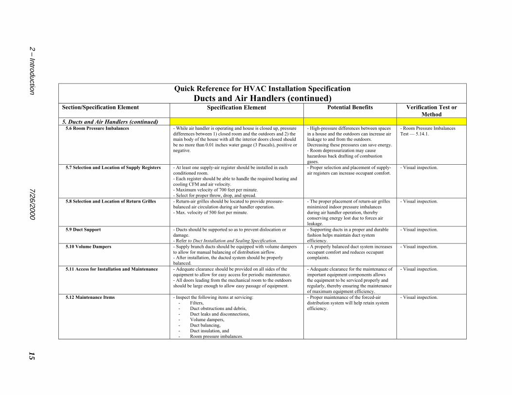
5. Ducts and Air Handlers (continued) 5.6 Room Pressure Imbalances - While air handler is operating and house is closed up, pressure
differences between 1) closed room and the outdoors and 2) themain body of the house with all the interior doors closed shouldbe no more than 0.01 inches water gauge (3 Pascals), positive ornegative.
- High-pressure differences between spacesin a house and the outdoors can increase airleakage to and from the outdoors.Decreasing these pressures can save energy.- Room depressurization may causehazardous back drafting of combustiongases.
- Room Pressure ImbalancesTest — 5.14.1.
5.7 Selection and Location of Supply Registers - At least one supply-air register should be installed in eachconditioned room.- Each register should be able to handle the required heating andcooling CFM and air velocity.- Maximum velocity of 700 feet per minute.- Select for proper throw, drop, and spread.
- Proper selection and placement of supply-air registers can increase occupant comfort.
- Visual inspection.
5.8 Selection and Location of Return Grilles - Return-air grilles should be located to provide pressure-balanced air circulation during air handler operation.- Max. velocity of 500 feet per minute.
- The proper placement of return-air grillesminimized indoor pressure imbalancesduring air handler operation, therebyconserving energy lost due to forces airleakage.
- Visual inspection.
5.9 Duct Support - Ducts should be supported so as to prevent dislocation ordamage.- Refer to Duct Installation and Sealing Specification.
- Supporting ducts in a proper and durablefashion helps maintain duct systemefficiency.
- Visual inspection.
5.10 Volume Dampers - Supply branch ducts should be equipped with volume dampersto allow for manual balancing of distribution airflow.- After installation, the ducted system should be properlybalanced.
- A properly balanced duct system increasesoccupant comfort and reduces occupantcomplaints.
- Visual inspection.
5.11 Access for Installation and Maintenance - Adequate clearance should be provided on all sides of theequipment to allow for easy access for periodic maintenance.- All doors leading from the mechanical room to the outdoorsshould be large enough to allow easy passage of equipment.
- Adequate clearance for the maintenance ofimportant equipment components allowsthe equipment to be serviced properly andregularly, thereby ensuring the maintenanceof maximum equipment efficiency.
- Visual inspection.
5.12 Maintenance Items - Inspect the following items at servicing:- Filters,- Duct obstructions and debris,- Duct leaks and disconnections,- Volume dampers,- Duct balancing,- Duct insulation, and- Room pressure imbalances.
- Proper maintenance of the forced-airdistribution system will help retain systemefficiency.
- Visual inspection.

7/26/200016 3 – Air Conditioners and Heat Pumps
Oversizing can lead to:• Higher equipment cost• Excessive loading/unloading• Frequent cycling• High conditioned-space humidity• Large conditioned-space temperature
swings• Low efficiency and high operating costs• Short equipment life• Occupant discomfort• Nuisance service calls
Chapter 3 – Air Condition-ers and Heat Pumps: Splitand Packaged Systems
3.1 Selection and Sizing of Space-Cooling Equipment: Specification.
3.1.1 Equipment Efficiency Ratings.(a) Air conditioners and heat pumps shouldcomply with the required efficiency of local orutility energy codes or, as a minimum, meetENERGY STAR efficiency levels.
(1) Central air conditioners and air-sourceheat pumps: minimum 12 SEER.(2) Air-source heat pumps: minimum 7.6HSPF.(3) Gas-fired heat pump: COP of 1.26 forheating and 1.32 for cooling.(4) Air conditioners and heat pumps shouldbe equipped with thermostatic expansionvalves, which compensate for variations inairflow and refrigerant charge better thanfixed orifice valves.
(b) Verification of Efficiency for SplitSystems.
(1) The efficiency of split systems must beverified by the latest edition of Directory ofCertified Unitary Equipment Standards byARI.(2) An evaporator coil should be installedwhich is verified to be a rated match with thecondenser coil, as listed in the currentDirectory of Certified Unitary EquipmentStandards by ARI.(3) All equipment should be properlytagged (nameplate) and easily identified bymake and model number.
(c) Verification of Efficiency for PackagedSystems.
(1) The efficiency of packaged systemsmust be verified by the latest edition ofDirectory of Certified Unitary EquipmentStandards by ARI.
Common sizing mistakes• Miscalculation of the square footage
and orientation of glazing• Using winter Air Changes per Hour
(ACH) rather than summer ACH• Miscalculation of summer ACH• Exaggeration of outdoor design
temperature (too warm for coolingequipment sizing)
• Sizing by capacity of existingequipment
• Sizing by rules of thumb.
3.1.2 Equipment Selection. Equipment shouldbe selected in accordance with the most recentedition of Residential Equipment Selection(Manual S) by ACCA, or a comparable industry-accepted method.3.1.3 Load Calculation. An accurate loadcalculation must be performed before equipmentis selected.
This load should be calculated with the mostrecent edition of Residential Load Calculation(Manual J) by ACCA, or a comparable industry-accepted method. Computer software programsbased on the most recent edition of Manual J areacceptable.(a) For the purpose of load calculation, theinterior design temperature used should be 75°Ffor cooling and 70°F for heating.

173 – Air Conditioners and Heat Pumps 7/26/2000
Advantages of proper sizing asopposed to oversizing are:
• Less expensive equipment• Ease of obtaining proper airflow• Can lead to greater occupant comfort• Can lead to longer equipment life• Quieter equipment operation• Leads to greater operating efficiency• Lower operating costs• Can lead to lower maintenance cost• Might lead to increased profit margin for
installer
(2) In cold climates, heat pumps should beselected so that total capacity is no greaterthan 125 percent of the total calculated load.(3) Select a heating balance point tempera-ture appropriate for outdoor design condi-tions without significantly over-sizing forcomfort cooling. Generally, low-rangebalance points are associated with climatesthat are predominately hot because theheating load is small relative to the coolingload. Conversely, high-range balance pointsare associated with climates that are pre-dominately cold because the heating load islarger.(4) The most appropriately selectedmanufacturer’s supplemental heat packageshould be installed so that the combinedoperation of the heat pump compressor andthe supplemental heaters satisfies the designheat load. Supplemental heaters assist theheat pump compressor in heating the housewhen the outdoor temperature is below thedesign balance point temperature.
3.1.4 Verification. Before installation, checksizing of the air conditioner or heat pump bycomparing Manual J load calculation with therated capacities (total, sensible and latent) atdesign conditions.3.1.5 Benefits. Oversizing comfort-coolingequipment can lead to efficiency losses of from 2-10 percent, higher equipment cost, poor dehu-midification performance caused by short cycles,and premature equipment degradation, accordingto reports by the U.S. EPA ENERGY STAR pro-gram.1 On the positive side, correctly sizedequipment can lead to reduction in the size of airdistribution ducts, resulting in increased effi-ciency of the ducted distribution system.3.1.6 Discussion. Using a mathematical sizingprocedure, such as Manual J, requires know-howand time. If a designer performs many loadcalculations each week, he or she will becomeproficient quickly and will become skilled fromexperience.
(b) For cooling-only equipment (not heatpumps) cooling capacity should be no morethan 1.15 times the calculated total coolingload.
Exception: If certified equipment is notmanufactured that meets the above require-ment, selected equipment may be as much asone-half ton larger than the calculated totalBtuh cooling load.
(c) Air conditioners and heat pumps withmulti-speed/variable-speed compressorsshould be sized within the cooling capacityrange of the equipment as specified by themanufacturer.(d) The latent cooling capacity of air condi-tioners and heat pumps must equal or exceedthe calculated latent load, with no specificexcess limit on latent capacity.(e) Select cooling airflow based on desiredsensible load ratio. Sensible load ratio =sensible load ÷ (sensible load + latent load).This will vary according to the characteristicsof the building and the local climate. (SeeManual S by ACCA, Section 1-5, Estimatingthe Cooling CFM.)(f) For heat pumps:
(1) In warm or moderate climates, heatpumps should be selected so that totalcapacity is no greater than 115 percent of thetotal calculated load.

7/26/200018 3 – Air Conditioners and Heat Pumps
Improper sizing leads to customer complaints,system inefficiencies, and premature equipmentdegradation. Because it is difficult to properlyadjust for improper sizing once the equipmenthas been installed, sizing “by the book” (ManualJ or a comparable method) is strongly encour-aged.
Many suppliers offer a free load-calculationservice to their installers. If such a service isused, it is vitally important that the installer makesure the method being used is based on Manual J.It is also important that the installer provideaccurate job information – such as house dimen-sions, insulation values, and window U-valuesand solar transmittance – to the person calculat-ing the load.
3.2 Placement of Equipment: Specifi-cation.
3.2.1 Follow manufacturer’s recommendationsfor placement of indoor equipment (some equip-ment is approved only for installation in condi-tioned space).3.2.2 Placement of split and packaged systemsshould minimize ductwork length.3.2.3 Allow sufficient space around indoor andoutdoor units for proper operation and servicing.Minimum clearances between equipment andadjacent structures, walls, or other objects shallbe:
(a) On the side containing the service panel,36 inches,(b) On all other sides, 12 inches,(c) Above vertical discharge unit, at least 48inches,(d) As specified by manufacturer and localcodes.
3.2.4 If visual inspection indicates that airflowto the outdoor coil might be restricted, verifywith this test:
(a) Run the unit for 15 minutes. Measure thetemperature of the ambient air to determine ifthe air entering the unit is significantly warmer
than the ambient air temperature. If it is,recirculated exhaust air is being pulled into theentering air stream.
3.2.5 Avoid placement of outdoor equipmentunder building eaves where collected rainwater,snow or ice can fall on the unit or airflow to theoutdoor coil may be restricted. Also avoid areaswhere snow drifts.3.2.6 For heat pumps, protect the outdoor unitfrom strong prevailing winds. If possible, locatethe outdoor unit on the downwind side of thebuilding in a sunny spot.3.2.7 For outdoor units, allow clearance forwater to drain away. Check the outdoor unitcabinet condensation and defrost drain holelocations and be sure they are not blocked by themounting pad or rack.3.2.8 Inform building occupants to keep thearea within 3 feet of the outdoor unit free of anyvegetation or structures that will obstruct airflowinto or out of the equipment.3.2.9 Where snowfall is:
(a) Below 20 inches annually, the outdoorunit may be placed on a ground-level concretepad constructed at least 3 inches above thesurrounding grade level,(b) From 20 to 40 inches annually, the out-door unit should be mounted on a rack thatelevates the equipment at least 12 inchesabove the ground-level pad,
More tons at the register, moremoney in installers’ pockets
If cooling systems are installed with theproper airflow at the coil, the correctrefrigerant charge and with tighter ductsystems, the effective installed coolingcapacity per ton significantly increases. Thisallows installers to put in smaller systemsand become more competitive in themarketplace. Improved installation practicesalso improve occupant comfort and reducecallbacks.
193 – Air Conditioners and Heat Pumps 7/26/2000
(c) More than 40 inches, the outdoor unitshould be mounted on a rack that elevates theequipment at least 16 to 24 inches above theground-level pad.
3.2.10 Benefits.(a) Proper clearances from permanent andtemporary obstructions, like snow, helpsensure maximum operating efficiency of thecooling equipment.
3.3 Indoor Coil Airflow: Specification.
3.3.1 Measured airflow over the indoor coilshould be the equivalent of 400 CFM per ton fora wet coil (condensation on coil) and 425 CFMper ton for a dry coil (no condensation on coil),plus or minus 50 CFM (for low sensible-load-ratio areas, the airflow will be on the low side ofthis CFM range, for higher sensible-load-ratioareas, the airflow will be on the high side of therange).3.3.2 Indoor coil airflow always should bemeasured after any duct and plenum sealing hasbeen completed, if practical. If this is not practi-cal, do a visual inspection for big leaks and leakybuilding cavity returns before measuring airflow.If large leaks are found, temporarily block thereturn side of the system. At that point, measur-ing airflow with a duct blower is probably theonly way to get a reasonable accurate CFM.3.3.3 Verification. Check airflow at installationstart-up and servicing.
(a) Most Accurate Method. The preferredverification method for airflow measurementis a calibrated duct blower. Refer to DuctBlower Test for Ensuring Proper Airflow,Section 3.13.1.(b) Alternate Method 1. SupplementaryHeat Test (temperature rise) for EnsuringProper Air-Handler Fan Flow. Refer to Sec-tion 3.13.2.(c) Alternate Method 2. Flow hood Test forEnsuring Proper Airflow. Refer to Section3.13.3.(d) Alternative Method 3. Static Pressure
Test for Estimating Airflow. Refer to Section3.13.4.
3.3.4 Benefits. Field studies suggest that about70 percent of installed residential cooling sys-tems have inadequate airflow at the indoor coil.2
One study showed that the inadequate airflow of320 CFM per ton, rather than 400 CFM, forfixed orifice (capillary tube) air conditionersresults in a loss of 6-15 percent efficiency.3
Thermal expansion valve (TXV) units do notsuffer as large a loss in efficiency for low air-flow.
3.4 Refrigerant Charge: Specification.
Manufacturer’s recommendations must be fol-lowed for refrigerant charge. Coil airflow shouldbe adjusted and verified before refrigerant chargechecked. Refrigerant charge-checking is particu-larly important with split-system air conditionersand heat pumps.3.4.1 Verification.
(a) Superheat Method. For systems withfixed metering devices (capillary tube or fixed
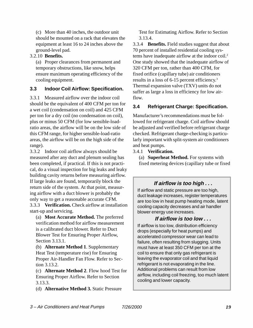
If airflow is too high . . .If airflow and static pressure are too high,duct leakage increases, register temperaturesare too low in heat pump heating mode, latentcooling capacity decreases and air handlerblower energy use increases.
If airflow is too low . . .If airflow is too low, distribution efficiencydrops (especially for heat pumps) andaccelerated compressor wear can lead tofailure, often resulting from slugging. Unitsmust have at least 350 CFM per ton at thecoil to ensure that only gas refrigerant isleaving the evaporator coil and that liquidrefrigerant is not evaporating in the line.Additional problems can result from lowairflow, including coil freezing, too much latentcooling and lower capacity.
7/26/200020 3 – Air Conditioners and Heat Pumps
Refer to Section 3.14.4.3.4.2 Benefits. Improper charge is probably themost significant contributor to loss of efficiencyfor space cooling equipment. Overcharging cancause flood back, slugging, and prematurecompressor failure. Undercharging preventsadequate cooling of the air passing over the coils,and can cause continuous operation, compressoroverheating and failure. Both of these conditionslower cooling efficiency. Field studies conductedover the last eight years found that about 75percent of installed cooling equipment wasimproperly charged. These studies show thatfixed-orifice equipment suffers an efficiency lossof 10-20 percent for overcharging and a 20percent loss in efficiency for a 20 percent under-charge of refrigerant. Thermal expansion valve(TXV) equipment is less sensitive of refrigerantlevels. A 20 percent overcharge or underchargefor typical TXV equipment demonstrated about a5 percent loss in efficiency.4
3.4.3 Discussion. As demonstrated by fieldtests, installing and servicing technicians fre-quently overlook or do not know the properprocedure for refrigerant charging. The efficiencylosses resulting from improper charging aresignificant enough to warrant verification atinstallation and servicing.
3.5 Refrigerant Lines, Split Systems,
When to connect your gaugesWhen servicing residential cooling systems, agauge manifold should not be connected everytime the system is serviced. This is because asmall amount of refrigerant escapes each timethe gauge is connected. Because many smallsystems have a critical refrigerant charge, thiscan adversely affect the system. Check therefrigerant charge unless you know the unit wasrecently charged using superheat or subcoolingand there are no indications of low capacity.
The problem of releasing refrigerant when check-ing the charge can be minimized by using a shortgauge line connector for the high side or by usinga small hand valve to keep the refrigerant in thesystem when disconnecting the gauges.
Indications of low refrigerant chargeinclude:• Inadequate cooling capacity• An overheated compressor motor
resulting from low suction pressure• If the system has a sight glass,
bubbles might indicate a low charge(a clamp-on “sight glass” may beused to electronically “listen” forbubbles)
Indications of refrigerant overchargeinclude:• Excessive condensation on com-
pressor housing as a result ofrefrigerant flood back
• In severe cases, compressor failure
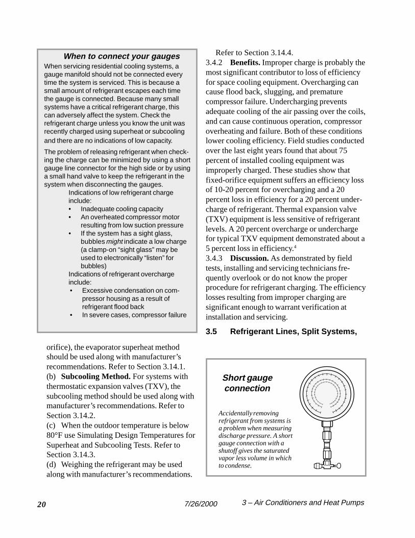
Short gaugeconnection
Accidentally removingrefrigerant from systems isa problem when measuringdischarge pressure. A shortgauge connection with ashutoff gives the saturatedvapor less volume in whichto condense.
orifice), the evaporator superheat methodshould be used along with manufacturer’srecommendations. Refer to Section 3.14.1.(b) Subcooling Method. For systems withthermostatic expansion valves (TXV), thesubcooling method should be used along withmanufacturer’s recommendations. Refer toSection 3.14.2.(c) When the outdoor temperature is below80°F use Simulating Design Temperatures forSuperheat and Subcooling Tests. Refer toSection 3.14.3.(d) Weighing the refrigerant may be usedalong with manufacturer’s recommendations.

213 – Air Conditioners and Heat Pumps 7/26/2000
Insulation and Protection: Specification.
3.5.1 Suction lines for split systems should beinsulated with a minimum of 3/8-inch thickclosed-cell elastomeric pipe insulation to preventcondensation and to slow heat transfer.3.5.2 Refrigerant line insulation exposed toweather should have a waterproof coveringproviding protection from ultraviolet light andweather damage.3.5.3 Refrigerant line length.
(a) The maximum horizontal length is 50feet. Check with equipment manufacturerwhenever horizontal length is greater than 50feet.(b) The maximum vertical length is 20 feet.Check with the manufacturer whenever thevertical length is greater than 20 feet.(c) Use long-radius bends, long-radiuselbows and a minimum of fittings to minimizeline friction losses.
3.5.4 Use long-radius bends and a minimum offittings to minimize line friction loses.3.5.5 Verification. Visual inspection for integ-rity of suction-line insulation. Visual inspectionand refrigerant charge testing for integrity of lineseal.3.5.6 Benefits. Suction refrigerant line insula-tion increases the operating efficiency of theequipment. Liquid lines should not be insulatedbecause the heat loss to the outdoor air duringcooling season increases the efficiency of theunit.
Refrigerant line leaks adversely affect operatingefficiency and can result in equipment break-down.
3.6 Fan-Delay Relay: Specification.
If not already included in the cooling equipment,heat pump or thermostat, a fan-delay relay shouldbe installed to continue the operation of the airhandler blower for a minimum of one minute, ora manufacturer’s present time delay, after thecompressor cycles off.
Exception: In hot, humid climates a fan-delayrelay is not required. In such a climate, it hasbeen found that in delayed shutdown of the airhandler fan can reintroduce significantamounts of water vapor back into the housedue to the evaporation of water on the evapo-rator coil.
3.6.1 Verification. Time the operation of theblower after the compressor shuts down.3.6.2 Benefits. The fan-delay relay increasesefficiency by 1) purging the ducted distributionsystem of conditioned air and 2) extracting themaximum cooling capacity from the evaporatorcoil.
3.7 Cooling/Heating ProgrammableThermostats: Specification.
3.7.1 Programmable thermostats should beinstalled for interior temperature control andshould have the following features:
(a) Thermostats should be ENERGY STAR
labeled.(b) Separate weekday and weekend pro-grams, each with up to four customizedtemperature settings – two for occupiedperiods and two for energy-saving periodswhen the house is unoccupied or when theoccupants are sleeping.(c) Thermostat must have ability to maintainroom temperature plus or minus 2°F ofsetpoint temperature.(d) Thermostat must have a hold feature thatallows users to temporarily override the
Thermostat education
Because programming is oftencomplicated, help the occupantsunderstand how to operate theprogrammable thermostat. This isespecially important during the initialinstallation and programming.

7/26/200022 3 – Air Conditioners and Heat Pumps
programmed settings without deleting them.(e) The maximum recommended setpointincrease for cooling is 8°F. The maximumrecommended setpoint decrease for heating is10°F.(f) Verification. Check for proper operationat installation.(g) Benefits. Savings for temperature offset(automatically turning the thermostat settingup, not off) vary depending on climate, equip-ment, and house envelope characteristics.Studies have demonstrated savings from 1-3percent per 1°F of eight-hour offset for heat-ing (for temperature offsets within a range of5-10°F). Two eight-hour setback periods per24-hour period double savings. For cooling,computer modeling and measured savingsshow a 2-5 percent savings per 1°F of eight-hour offset.
5 Customers will complain about
the amount of time required to achieve acooling setpoint during a heat wave, unless theextra time is factored into the time settings ofthe thermostat.
3.7.2 Thermostat should be mounted on aninterior wall in an area of average temperatureand away from direct sunlight, distributionsupply airflow, stairwells, water pipes, appli-ances and sources of electrical interference.
3.8 Indoor Heat Pump Thermostat,Heating Operation: Specification.
3.8.1 Thermostats should be “intelligent-recovery, staging,” or “ramping” types that donot allow supplemental heat to activate a) duringtemperature pick-up at the end of an automati-cally programmed temperature setback or b)when an occupant increases the thermostat offset.3.8.2 Change-over from heating to cooling andback must be manually activated; it may not beautomatic. (Exception: A full-featured comfortmanagement zoning system, which maintains adead band between the cooling and heatingsetpoints.)3.8.3 Thermostats that are not “intelligent-
recovery” or “ramping” are not acceptable unlessan outdoor lockout thermostat is used as a com-ponent of the control system (see Section 3.9).3.8.4 Indoor thermostat must have an emer-gency heat switch that will:
(a) Permit all supplemental heaters to beenergized under control of the indoor thermo-stat – with the compressor and outdoor ther-mostat bypassed – when the compressor orrefrigerant system is inoperative; and(b) Activate an indoor indicator light when-ever the system is operating on emergencyheat.
3.8.5 Verification. Verify proper operation atinstallation.3.8.6 Benefits. If a heat pump thermostat is notworking properly, the expensive supplementaryheat can be unnecessarily activated by an increasein thermostat temperature setting or during pick-up time after a programmed temperature offset.This can lead to higher energy costs for tempera-ture setback.3.8.7 Discussion. Because occupants adjustcomfort thermostats, and programming is oftencomplicated, make certain the occupants under-
Heat pump defrost cycleThe outdoor coil refrigerant of a heat pumpoperates at a temperature below freezingwhen the outdoor temperature is below45OF (the outdoor coil operates at atemperature 20-25OF lower than theoutdoor air temperature). The need fordefrost varies with the outdoor airconditions and the running time of the heatpump.
Defrost is accomplished by reversing theheat pump system to the cooling mode andstopping the outdoor fan. This temporarilymakes the outdoor coil the condensing coilwithout a fan, so the coil gets quite warmquickly, even in the coldest weather.

233 – Air Conditioners and Heat Pumps 7/26/2000
stand how to operate the programmable thermo-stat. This is especially important at the initialinstallation of the device.
3.9 Air-Source Heat Pump Outdoor-Lockout Thermostat, Heating Operation:Specification.
3.9.1 An outdoor-lockout thermostat is requiredregardless of the type of indoor thermostatinstalled.3.9.2 The outdoor thermostat must lock out thesupplemental heat when the outdoor temperatureis greater than the heat pump balance point(usually 25-40°F, depending on the climate).Caution: Emergency heat should not be subjectto lockout under any circumstances.3.9.3 Wire the outdoor-lockout thermostat sothe supplemental heater is not subject to lockoutduring the outdoor coil-defrost cycle.3.9.4 Locate the outdoor-lockout thermostat ina location that will allow the sensing bulb todetermine the true outdoor temperature, not thesupply or outdoor air-stream temperatures.3.9.5 Verification. Verify proper operation atinstallation.3.9.6 Benefits. If a non-intelligent or non-ramping comfort thermostat is installed, expen-sive supplementary heat can be unnecessarilyactivated by an increase in thermostat tempera-ture setting or during pick-up time after a pro-grammed setback. This can lead to higher energycosts for temperature setback. An outdoor-lockout thermostat prevents this from occurring,but allows supplementary heat to be activatedduring the outdoor-coil defrost cycle.
3.10 Heat Pump Defrost Control, Heat-ing Operation: Specification.
If installing a new heat pump, select a modelwith microprocessor defrost control (this control“learns” to defrost only when needed). For anexisting system, if the defrost control is anelectronic combination time/temperature devicewhere defrosting the outdoor coil is initiated at a
Access for technicians
If technicians do not have easy access toequipment components that require periodicinspection and cleaning, these componentswill go without service and equipmentefficiency will suffer. Unfortunately, techniciansfrequently are provided with too little space toinstall the equipment with adequate clearancefor maintenance.
If possible, it is best if the installing technicianis part of the design team so that he canensure there is ample space for theequipment and ductwork.
pre-selected time interval (provided the outdoorcoil is below the present initiation temperature),set the time interval to provide the highest defrostefficiency for local weather conditions.3.10.1 Verification. Follow manufacturer’sverification procedures.3.10.2 Benefits. Excessive defrosting of theoutdoor coil during cold weather reduces theefficiency of heat pump operation. Of course, aniced outdoor coil also reduces efficiency. Thecontrol for defrosting of the outdoor coil must beadjusted to optimize efficiency – just enough tokeep the coil free of ice without any unnecessaryoperation.
3.11 Access for Maintenance: Specifica-tion.
3.11.1 When installing comfort cooling equip-ment, an open space shall be provided aroundelectrical panels and equipment sections requir-ing servicing. These spaces shall be a minimumof 30 inches wide by 36 inches deep, or asspecified by local code. Items requiring mainte-nance include filters, air handler blowers, refrig-eration coils and controls.3.11.2 Minimum clearances between equipmentand adjacent structures, walls or other objectsshall be:

7/26/200024 3 – Air Conditioners and Heat Pumps
(a) On the side containing the service panel,36 inches;(b) On all other sides, 12 inches, or(c) As specified by manufacturer and localcodes.
3.11.3 All doors leading from the mechanicalroom to the outdoors should be large enough toallow easy passage of equipment.3.11.4 Verification. Visual inspection at installa-tion.3.11.5 Benefits. Adequate clearance for themaintenance of important equipment componentsallows the equipment to be serviced properly andregularly, thereby ensuring the maintenance ofmaximum equipment efficiency.
3.12 Maintenance Items: Specification.
3.12.1 Follow manufacturer’s regularly sched-uled maintenance program guidelines.3.12.2 All equipment literature, including instal-lation instructions and maintenance records,should be affixed to the equipment by means of aplastic storage pocket or other appropriatemeans.3.12.3 The following items should be inspectedand properly maintained at annual servicing forthe purpose of maintaining system efficiency.
(a) Filters. Verify with visual inspectionwhether filter requires cleaning or replacement
(1) Clean or replace filter(s) as required.Do not attempt to clean a filter that is de-signed to be thrown away.(2) Make sure the filter compartment(s) aretight fitting. Make tight fitting or seal asnecessary.(3) If appropriate, educate occupants aboutrecommended filter cleaning or changing.
(b) Indoor and outdoor coils. Check fordebris, cleanliness and any obstruction to freeairflow through the coils. Clear debris andclean, if necessary.
(1) To clean outdoor coil:[i] Turn off power to condensing unit.[ii] To avoid damaging the coil fins,
clean the condenser coil using a bristlebrush, or vacuum using a soft bushattachment, or lightly spray water or othercleaner.[iii] Turn power to condensing unit backon.
(2) To clean indoor coil:[i] Turn power off to air handler andcompressor.[ii] If no access panel exists, create a re-sealable access panel in a workmanlikemanner.[iii] The indoor coil cleaning shall bedone using a brush, vacuum, or air pres-sure. If a cleanser is used, rinse the coilwith water from a spray bottle beforeproceeding with the next step.[iv] Check condensate drain line forclogging, rust, etc. Clean as needed.[v] Access panel shall be closed andsealed with approved tape or mastic.Identify access panel with permanentlabel or marker.[vi] Turn power back on to air handlerand compressor.
(c) Indoor coil airflow. Measure the coilairflow to verify it is within the recommendedrange. Use procedures in Section 3.3. Cleancoil if required.(d) Refrigerant charge. Refrigerant chargeshould match the manufacturer’s recommen-dations. Verify refrigerant charge at servicingunless you know the unit was recently chargedusing superheat or subcooling and there are noindications of low capacity. See Section 3.4.(e) Refrigerant lines. Check for damage tolines and fittings. Inspect for damage to lineinsulation.(f) Air handler blower belts.
(1) Check for wear, slippage and properalignment.(2) Adjust belt tension or replace belt ifrequired.
(g) Air handler blower motor.

253 – Air Conditioners and Heat Pumps 7/26/2000
(1) Lubricate according to manufacturer’srecommendations.(2) Check the blower motor and blowerbearings, whether belt-driven or direct-drivewith the power off.
[i] Hold the motor casing with one handand grab the shaft with the other hand.Move the shaft up and down and side toside. The shaft will, under normal condi-tions, slide in and out of the motor case aslight amount. However, if there isexcessive “play” or movement (side toside), or if there is a “sticky” spot as youspin the shaft, the bearings are bad. If thisis the case, it is recommended that themotor be replaced.[ii] Belt-driven blower bearings can bechecked by turning off the power to theblower, disconnecting the belt and spin-ning the blower with your hand; theblower wheel should rotate several timeson its own. If the bearings are bad, theyshould be replaced.
(h) Air handler blower vanes.(1) Check for proper rotation of blower.Adjust if necessary.(2) Check for buildup of dust, dirt anddebris. Any dirt buildup on the blower vaneswill greatly reduce airflow.(3) Clean if necessary.
[i] Turn off power to blower.[ii] Clean blower vanes using a brush,vacuum or hot water. If water or cleans-ers are used, rinse the blower componentsand allow them to dry before proceeding.Protect the blower motor from water andchemicals.[iii] When the blower is extremely dirty,the blower assembly should be removed,separated from the blower motor andpower washed. Allow the blower compo-nents to dry before proceeding. Reinstallthe blower assembly and motor.[iv] Turn power to the blower unit back
Cleaning indoor and outdoor coils
Removing a metal panel at the end, or accessing thea-coil from underneath, are two common ways ofcleaning its underside.
Condenser coils can get loaded with dirt, grass,and lint. This debris can be easily removed with abrush and gentle spray of water from the insideof the coil. This condenser should be 3 inchesabove the surrounding ground on a concrete padbut is not.
Clean coil from side orunderneath for upflowfurnaces.

7/26/200026 3 – Air Conditioners and Heat Pumps
on.[v] Check and adjust airflow across thecoil if necessary.[vi] Controls. Verify the proper operationof all controls, including high-limitswitches, comfort thermostats, defrostcontrols and outdoor-lockout thermostats.See Sections 3.6, 3.7, 3.8, 3.9, and 3.10.
3.12.4 Benefits. Proper maintenance of equip-ment and controls will retain system efficiency,extend the life of the equipment and ensureoccupant comfort.3.12.5 Discussion. The maintenance items listedhere can impact system efficiency. Not all main-tenance items are included here, especially thosethat do not directly influence system efficiency.
Verification Tests
3.13 Tests for Ensuring Proper Air-Handler Airflow.
3.13.1 Duct-Blower Test for Ensuring ProperAirflow.
(a) Objective of test. The measurement ofair-handler airflow. The most accurate test ofthe air handler airflow is done with a ductblower in conjunction with the air handler’sblower. Airflow is measured after duct-leakage testing and duct sealing becausemeasuring airflow in leaky ducts is inaccurate.During the test, the return is blocked so allreturn air comes through the duct blowerwhere the airflow can be measured.(b) Required equipment.
(1) Duct blower, a fan-powered flow-measuring device.(2) A digital or analog manometer andtables for translating pressures to flows. Thetables for the specific duct blower beingused.(3) A contractor using an Aeroseal Incorpo-rated, aerosol-applied duct-sealant system oran equivalent product.
(c) Setup.
Connecting the duct blower
Connecting the duct blower to a single centralreturn gives an accurate airflow reading as long asthe ducts have been sealed to specifications listed inChapter 5.
Blocking the return plenum and connecting the ductblower directly to the air-handler cabinet works wellfor systems with more than one return register.
Return plenumtemporarilydisconnectedand opening toair handlerblocked here.
Digitalmanometermeasuresbothpressureandairflow.
Flexible ductconnectsduct blowerto singlereturnregister.

273 – Air Conditioners and Heat Pumps 7/26/2000
(1) Set up a static pressure gauge to mea-sure the duct pressure at the supply plenum,or a few feet away from the supply plenum,in a main supply trunk with reference to thehouse. Once the measurement probe islocated properly (select a location that givesthe highest pressure), tape the static pressureprobe to hold it in place. The openings in theprobe must be perpendicular to the airflow inthe plenum or duct.(2) Make sure all supply registers andreturn grilles are open and not taped. Leavefilters installed. If filters are dirty, replace orclean.(3) Perform required duct sealing to con-form to standards explained in Section
5.13.1 before measuring airflow.(d) Conducting the test.
(1) Turn on the system air handler bysetting the thermostat fan switch to the “on”position. Systems without a fan “on” switchwill need to run in cooling mode to operateat the higher of two speeds (heating usuallyuses a lower speed), or in heating mode forheating-only systems. If the air handlerprovides both heating and cooling, makesure you activate the fan speed for theappropriate application – heating or cooling.A useful verification check is to clamp anammeter around the color wire you thinkcorresponds to heating or cooling to deter-mine if the wire is energized. Proceed withthe test.(2) Make sure the system air handler is onhigher speed (for cooling). Measure andrecord the normal operating duct staticpressure with reference to the house. This isthe reference pressure, Psp, to be used later.Do not remove the static-pressure probe afterthis measurement.(3) Shut off power to the air handler.Connect the duct blower to blow into thesingle return register or into the air handler atthe blower compartment. All the return airshould now come through the duct blower.Use the following procedures to connect theduct blower.
[i] For single-return systems: Remove thegrille at the single return register. Connectthe duct blower through its flexible tubeor directly to the register.[ii] For multiple-return systems: Blockthe return plenum’s main return entry tothe air handler. Filters are often located ina good location for this temporary block-age. Alternatively, the main return can bedisconnected and supported temporarily,while this large duct is moved slightly toblock its opening into the air handler. Ifthe duct blower is connected to an air
System airflow test using theduct blower
duct blower
air handler
return air(blocked off)
pressuremanometer
airflow manometer
The duct static pressure achieved during normaloperation is reproduced, using the duct blower. Thereturn is blocked when it isn’t used to connect the ductblower, so that all the system’s air must travel throughthe duct blower where it is measured by the airflowmanometer.
No return airflowthrough hereduring the test
supply air

7/26/200028 3 – Air Conditioners and Heat Pumps
handler, located outside the conditionedspace, the door or access panel betweenthe conditioned space and the air handlerlocation must be opened.
(4) Turn on the air-handler fan. Make surethe air-handler fan is running on its normallyhigher speed – at the speed corresponding toyour desired airflow test – heating or cool-ing.(5) Turn on the duct blower to blow intothe air handler, increasing airflow until themanometer measuring supply-plenum staticpressure reads the same as in Section 3.13.1(d)(2), Psp, with reference to the house.(6) Measure and record the airflow throughthe duct blower. Refer to the duct-blowerinstruction book, if necessary. This is total
system airflow in cubic feet per minute(CFM).
[i] If supply-duct pressure cannot beachieved with the duct-blower fan and theair-handler fan turned on, remove theflexible duct extension – if you have usedit – from the duct blower, and connect theduct blower directly to the air-handlercompartment. If high enough pressurestill cannot be reached, proceed to thenext step, Section 3.13.1 (d) (6) [ii].[ii] With the duct-blower and the air-handler fans turned on, measure andrecord the following: a) the maximumpressure (Pmax) with reference to thehouse, and b) the maximum duct blower-fan flow in CFM (Bmax) at the maximumpressure, Pmax. Then use the equation inthe sidebar (left) to estimate total air-handler airflow, Q.
(e) Interpreting the results. This airflowmeasurement should yield an accuracy of ±5percent or better.
3.13.2 Supplementary Heat Test (temperaturerise) for Ensuring Proper Air Handler FanFlow.
(a) Objective of test. This test measures air-handler airflow for 1) heat pumps with electricsupplementary heat and 2) electric resistancefurnaces with cooling coils.A simple method for determining systemairflow for this equipment is measuring thetemperature rise across electric-resistanceheating coils. These electric-resistance coilsshare the same air stream as the heat pump’sindoor coil, or the external evaporator coil ofthe air conditioner. The measured temperaturerise, together with the wattage of the resis-tance heat, is used to calculate airflow.(b) Limitations of test. This test is validonly for 1) heat pumps with electric supple-mentary heat and 2) electric resistance fur-naces with cooling coils.(c) Required equipment.
Where: Q = Total estimated air handler airflow, in CFM;
Bmax
= maximum duct blower fanflow in CFM at maximum ductblower pressure with duct blowerfan and air handler fan on as inSection 5.1.1 (d)(6)
Pmax
= maximum pressure, ductwith reference to the house,attainable with duct blower and airhandler fan on as in Section 5.1.1(d)(6)
Psp
= normal operating ductpressure with reference to thehouse, with the air handler on highspeed as in Section 5.1.1 (d)(2).
If duct blower cannot supply theairflow needed, use this equation:
Q =
Bmax
Pmax
Psp

293 – Air Conditioners and Heat Pumps 7/26/2000
(1) Volt-ohmmeter(2) Ammeter(3) Accurate thermometer
(d) Conducting the test.(1) Engage electric resistance heating coilsand the blower, making sure that the heatpump’s compressor is off.(2) Measure amperes of current, feedingboth wires to the electric-resistance heatstrips and add these ampere measurementstogether.(3) Measure voltage between the two hot-wires feeding the strips.(4) With a radiation-shielded thermometer,measure the temperature rise (delta T) of theair across the heat strip, after at least 5minutes of operation. Keep the thermometerout of the line-of-sight of the hot coils. Movethe thermometer around, looking for a stableaverage supply temperature.(5) Apply this formula to calculate airflow
in CFM: CFM = 3.16(volts x amps)/delta T.(e) Interpreting the results. This airflowmeasurement should match system-designairflow and manufacturer’s specifications. Theaccuracy of this test depends on the averagingof the measured temperatures, which can varywidely. Measuring a temperature profileacross both the length and width of the ductwith an accurate thermometer, and averagingthe temperature profiles with a calculator, willusually produce accuracy of around ±25percent.
3.13.3 Flow Hood Test for Ensuring ProperAirflow.
(a) Objectives of test. This test measures thefairly laminar airflow at return registers.Measuring supply-register airflow isn’t asaccurate because supply air is more turbulentand because supply registers along walls don’tallow the flow hood to be centered over them.
240
Supplemental heat test or temperature-rise test
The increase in temperaturebetween these thermometers isthe temperature rise.
Adding these two amperage valuesgives total amperes going into theheating coil.
Measure voltage across the twohot leads of the circuit.
When measuring the temperature rise across the resistance heat, keep the probes out of a direct line-of-sight withthe coils to prevent a false reading from infrared radiation. Taking several temperature readings in a grid at eachlocation makes this test more accurate.
supplyreturn
air handler
ammeter
thermometer
volt meter

7/26/200030 3 – Air Conditioners and Heat Pumps
The flow-hood inlet must be larger than thereturn registers, although 10 percent of theregister may be blocked with tape to allow theflow hood to cover the entire opening.(b) Limitations of test. This test works beston systems with one to four return registerslocated in areas where a flow hood can coverthe registers and be centered over them.Return airflows should be well within therange of the flow hood’s accuracy.(c) Setup. Perform required duct sealing toconform to standards explained in Section5.13.1 before measuring airflow.(d) Conducting the test.
(1) Turn on the air handler to run at thehigher fan speed, normally used for cooling.(2) Center the flow hood over the returnregister, covering it completely. If the regis-ter is larger that the flow hood, seal up to 10percent of the register with tape beforecovering it.(3) Read and record the airflow. Addtogether the airflows of the return to get thetotal system airflow.
3.13.4 Static Pressure Test for EstimatingAirflow.
(a) Objective of Test. This test can roughlyestimate airflow if the manufacturer’s table forstatic pressure versus airflow is available. It isoften used to judge the cleanliness of anevaporator coil.(b) Limitations of the test. Static pressurecan vary widely from point to point within themeasurement area, especially when ducts takean abrupt change of direction near the airhandler. Access to both sides of the coil fortesting static pressure can be difficult andrequires great care and planning to avoiddamaging the coil.(c) Required equipment.
(1) Digital or analog manometer(2) Static pressure probe or pitot tube(3) Drill and bits(4) Screw or nut drivers
(d) Conducting the test.(1) Use a drill with a drill-stop to establish ahole or use existing openings to gain accessto both sides of the coil or air handler.
Static pressure test for estimating airflow
staticpressureprobe
Tip faces intoairflow
analog ordigitalmanometer
Static pressure difference across theair handler can estimate airflowusing tables in manufacturer’sliterature.
Static pressure difference acrossthe filter detects dirt and gives arough estimate of airflow usingmanufacturer’s information.
Measuring differential pressure isshown here. When taking the twoindividual readings with one hoseand probe, subtract absolutevalues of the two pressuremeasurements.

313 – Air Conditioners and Heat Pumps 7/26/2000
(2) Attach two static pressure probes to tubesleading to the ports of the manometer. Foranalog manometers, attach the high-side portto the probe inserted downstream of the coilor air handler.(2) Optional. If only one static pressureprobe or pitot tube is available, take thereadings on each side of the coil and subtracttheir values. Disregard positive or negativesigns given by a digital manometer.(3) Consult manufacturer’s literature for atable, relating static pressure difference toairflow. Find airflow for the static pressuremeasured above.
(e) Interpreting the results. Coils and airhandlers have static pressure ranging from0.20 IWC (50 Pascals) and 0.80 IWC (200Pascals) as found in the field. This variationresults from the air-handler and duct design,
duct size and obstructions to airflow.
3.14 Tests for Ensuring Proper Refriger-ant Charge.
3.14.1 Evaporator Superheat Test for Refrig-erant Charge.
(a) Objective of test. Determine properrefrigerant charge for the efficient and safeoperation of the equipment. Adjusting thecharge to produce the ideal superheat tempera-ture for the current indoor and outdoor tem-peratures optimizes system performance andefficiency. Superheat is an excellent indicatorof correct system performance for all types ofair conditioners and heat pumps with capillaryor fixed-orifice expansion devices, operatingin the cooling mode.(b) Limitations of test. Followmanufacturer’s recommendations for the
DBWB
9072
52
Evaporator superheat test
evaporator
suctionservicevalve
indoor wet bulbtemperature
outdoor dry bulbtemperature
low-pressure gauge
Thermometer attached tosuction line exiting evaporatormay be used as an alternativeto suction pressure.
Low-pressure gauge reads67 psig, which correspondsto a 39° evaporatingtemperature. Superheat is52° – 39° = 13°F.
condenser
compressor
The correct evaporator superheat is obtained from a superheat table that lists superheat values, depending onoutdoor dry bulb and indoor wet bulb air temperatures. The correct superheat value is then compared to themeasured superheat value as determined above.
air handler
52
72 90

7/26/200032 3 – Air Conditioners and Heat Pumps
evaporator-superheat test. If manufacturer’srecommendations are not available, abide bythese limitations:
(1) This test is only to be used for fixedorifice/capillary systems and not for thermo-static expansion value (TVX) systems.(2) This test should only be done when theoutdoor temperature is at least 80°F. Indoortemperature should be higher than 70°F.
(c) Required equipment.(1) Refrigeration gauge set.(2) Accurate, contact digital thermometeror infrared thermometer with auxiliarydevices (as needed) to accomplish goodcontact for the thermometer probe.(3) Sling psychrometer.
(d) Conducting the test with outdoortemperature greater than 80°F.
(1) Determine the recommended superheattemperature from the permanent stickerinside the condenser unit, frommanufacturer’s literature, or from amanufacturer’s slide rule.(2) Measure the compressor-suction pres-sure at the suction-service valve. Add 2pounds per square inch of gauge pressure(psig) for line losses between the evaporatorand compressor. Then convert this pressureto a boiling-point temperature using tem-perature-pressure tables for the system’srefrigerant.(3) Measure the suction-line temperature atthe evaporator’s outlet.(4) Subtract the boiling-point temperaturedetermined in Section 3.14.1 (d)(1) from themeasured temperature in Section 3.14.1(d)(2). This is the superheat temperature.(5) Measure the dry bulb temperature of theair entering the outdoor coil.(6) Measure the wet bulb temperature ofthe return air.(7) Find the ideal superheat value from thetable or slide rule provided by the manufac-turer.
(8) If the actual superheat is greater thanthe ideal superheat obtained from the table,add refrigerant, 2-4 ounces at a time.(9) If the actual superheat is less than thetheoretical, remove refrigerant, 2-4 ounces ata time. Refrigerant must be removed into anempty Department-of-Transportation-ap-proved (DOT-approved) recovery cylinderor one containing the same refrigerant as thesystem.(10) Allow the system to run for 10 minutesto adjust to the new operating conditions.Repeat the superheat procedure until themeasured superheat temperature is withinone degree of the ideal superheat tempera-ture.
(e) Interpreting the results. Correcting thecharge to produce the manufacturer’s recom-mended superheat temperature ensures effi-cient operation of the heat pump or air condi-tioner.
3.14.2 Subcooling Test for Ensuring ProperRefrigerant Charge.
(a) Objective of test. Determine properrefrigerant charge for the efficient operation ofthe equipment.(b) Limitations of test. Followmanufacturer’s recommendations for theevaporator subcooling test. If manufacturer’srecommendations are not available, abide bythese limitations: This test is only to be usedfor thermal expansion valve (TXV) systemswhen the outdoor temperature is at least 80°F.(c) Required equipment.
(1) Refrigeration gauge set.(2) Accurate, contact digital thermometeror infrared thermometer with auxiliarydevices as needed to accomplish goodcontact for the thermometer probe.
(d) Setup.(1) Heat pump or air conditioner should berunning in the cooling mode for 10 minutesprior to the test.
(e) Conducting the test with outdoor

333 – Air Conditioners and Heat Pumps 7/26/2000
temperature greater than 80°F.(1) Measure the compressor dischargepressure. Convert this pressure to the con-densing temperature, using temperature-pressure tables for the system’s refrigerant.Or, simply measure the surface temperatureof a protruding loop of tubing in the centerof the condenser between that section’s inletand outlet.(2) Measure the temperature of the liquidrefrigerant leaving the condenser.(3) Subtract the liquid-refrigerant tempera-ture measured in Section 3.14.2 (e)(2) fromthe condensing temperature determined inSection 3.14.2 (e)(1). This is the subcoolingtemperature.(4) Find the correct subcooling temperaturefrom the permanent sticker inside the con-
denser unit, from manufacturer’s literature orfrom a manufacturer’s slide rule. Addrefrigerant if the measured subcoolingtemperature is below the recommendation.Subtract refrigerant if the subcooling tem-perature is higher than recommended. Re-frigerant must be removed into an emptyDOT-approved recovery cylinder or onecontaining the same refrigerant as the sys-tem.(5) Allow the system to run for 10 minutesto adjust to the new operating conditions.Repeat the subcooling procedure, until themeasured subcooling temperature matchesmanufacturer’s recommendations or is 10° to15°F.(f) Interpreting the results. The meteringdevice must be supplied with subcooled
Subcooling test
evaporatorair handler
compressor
liquid service valve
thermostatic expansion valve (TXV)
Condensing temperature mayby checking discharge liquid-line pressure and converting it tocondensing temperature using arefrigerant temperature-pressuretable.
high-pressure gauge
condenser
Differential thermometer measures subcooling directlyby subtracting condensing temperature fromrefrigerant temperature at the expansion valve.
A subcooling test can be done on most airconditioners and heat pumps. Subcooling isprimarily used to access TXV systems.

7/26/200034 3 – Air Conditioners and Heat Pumps
72 93
liquid. This is one of the main design re-quirements of all refrigeration systems. Asubcooling temperature between 10° and15°F is common for a properly functioningresidential air conditioner, but it is better touse manufacturer’s specifications forsubcooling if they are available.
3.14.3 Simulating Design Temperatures forSuperheat and Subcooling Tests.
(a) Objective of test. Blocking a portion ofthe condenser’s airflow makes it possible toperform a superheat or subcooling test whenoutdoor temperature is below 80°F becausethe reduced airflow simulates hot weather.(b) Required equipment.
(1) Digital thermometer. (Note: A differen-tial digital thermometer makes this testeasier).(2) Probes for measuring air temperature andrefrigerant-tubing surface temperature.
(3) A tarp or piece of cardboard or plasticfor blocking the condenser.
(c) Conducting the test(1) Measure the condensing temperature bymeasuring the surface temperature of acondenser pipe loop near the vertical centerof the condenser.(2) Measure outdoor temperature andsubtract from condensing temperatureobtained in (1) to arrive at the “condensersplit.”(3) To simulate 95°F outdoor temperature,add this condenser split to 95°F, the outdoortemperature being simulated (design tem-perature).(4) Block condenser airflow until reachingthe condensing temperature obtained in (3).Block equal areas of each condenser circuit.Or, block the fan outlet in such a way as toretard the airflow equally across the outlet of
compressor
condenser split = 21°F
Block condenser inlet or outlet to raise condensingtemperature to simulate 90°F outdoor conditions.
Simulating hot outdoor temperatures for superheat and subcooling tests
Condenser split of 21°Fadded to 90°F. When thiscondensing temperature isachieved, superheat orsubcooling tests can beconfidently performed.
Hot outdoor conditions are simulated by first measuring the condenser split during existing outdoor conditions.Then this temperature is added to 90°F and the condenser is blocked until that condensing temperature is reached– in this case, 111°F.
After measuringcondenser split,block part of thecondenser.
pipe-clamptemperatureprobe
airstreamtemperatureprobe
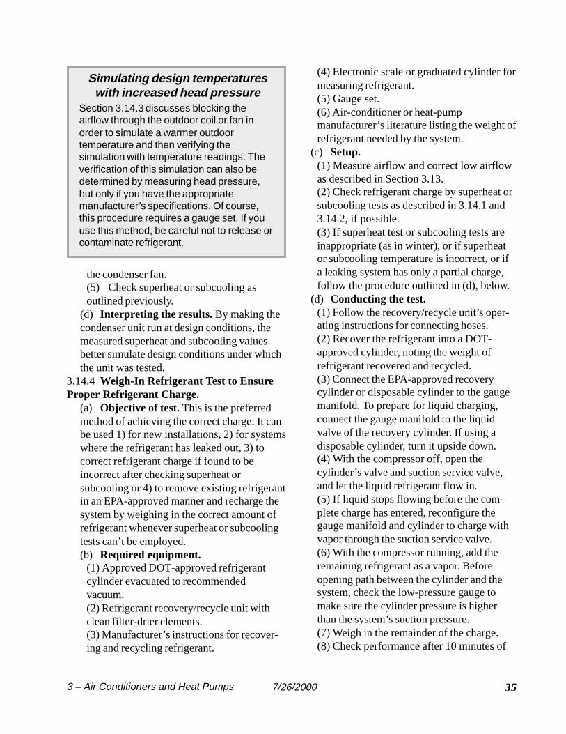
353 – Air Conditioners and Heat Pumps 7/26/2000
Simulating design temperatureswith increased head pressure
Section 3.14.3 discusses blocking theairflow through the outdoor coil or fan inorder to simulate a warmer outdoortemperature and then verifying thesimulation with temperature readings. Theverification of this simulation can also bedetermined by measuring head pressure,but only if you have the appropriatemanufacturer’s specifications. Of course,this procedure requires a gauge set. If youuse this method, be careful not to release orcontaminate refrigerant.
(4) Electronic scale or graduated cylinder formeasuring refrigerant.(5) Gauge set.(6) Air-conditioner or heat-pumpmanufacturer’s literature listing the weight ofrefrigerant needed by the system.
(c) Setup.(1) Measure airflow and correct low airflowas described in Section 3.13.(2) Check refrigerant charge by superheat orsubcooling tests as described in 3.14.1 and3.14.2, if possible.(3) If superheat test or subcooling tests areinappropriate (as in winter), or if superheator subcooling temperature is incorrect, or ifa leaking system has only a partial charge,follow the procedure outlined in (d), below.
(d) Conducting the test.(1) Follow the recovery/recycle unit’s oper-ating instructions for connecting hoses.(2) Recover the refrigerant into a DOT-approved cylinder, noting the weight ofrefrigerant recovered and recycled.(3) Connect the EPA-approved recoverycylinder or disposable cylinder to the gaugemanifold. To prepare for liquid charging,connect the gauge manifold to the liquidvalve of the recovery cylinder. If using adisposable cylinder, turn it upside down.(4) With the compressor off, open thecylinder’s valve and suction service valve,and let the liquid refrigerant flow in.(5) If liquid stops flowing before the com-plete charge has entered, reconfigure thegauge manifold and cylinder to charge withvapor through the suction service valve.(6) With the compressor running, add theremaining refrigerant as a vapor. Beforeopening path between the cylinder and thesystem, check the low-pressure gauge tomake sure the cylinder pressure is higherthan the system’s suction pressure.(7) Weigh in the remainder of the charge.(8) Check performance after 10 minutes of
the condenser fan.(5) Check superheat or subcooling asoutlined previously.
(d) Interpreting the results. By making thecondenser unit run at design conditions, themeasured superheat and subcooling valuesbetter simulate design conditions under whichthe unit was tested.
3.14.4 Weigh-In Refrigerant Test to EnsureProper Refrigerant Charge.
(a) Objective of test. This is the preferredmethod of achieving the correct charge: It canbe used 1) for new installations, 2) for systemswhere the refrigerant has leaked out, 3) tocorrect refrigerant charge if found to beincorrect after checking superheat orsubcooling or 4) to remove existing refrigerantin an EPA-approved manner and recharge thesystem by weighing in the correct amount ofrefrigerant whenever superheat or subcoolingtests can’t be employed.(b) Required equipment.
(1) Approved DOT-approved refrigerantcylinder evacuated to recommendedvacuum.(2) Refrigerant recovery/recycle unit withclean filter-drier elements.(3) Manufacturer’s instructions for recover-ing and recycling refrigerant.

7/26/200036 3 – Air Conditioners and Heat Pumps
Weighing in a refrigerant charge First, charge with liquid refrigerantthrough the liquid service valve withthe compressor off.
Disposablecontainer must beinverted for liquidcharging. DOT-approvedcontainer remainsupright for liquidcharging becauseit has a liquidvalve.
If liquid stops flowing before the total chargehas entered the system, run the compressorand add the remainder as vapor through thesuction service valve.
Weighing in refrigerant corrects for low charge as determined by superheat or subcooling tests. If refrigerant mustbe withdrawn, a recovery/recycle unit must be used. For heat pumps or air conditioners charged during outdoortemperatures less than 70°F, the system must be evacuated in an EPA-approved manner and recharged by weight.
operation using superheat test, subcoolingtest, or a combination of other indicatorsincluding: temperature difference acrossevaporator and condenser, compressorsuction and discharge pressures, evaporator-and condenser-saturation temperatures, andother indicators as provided by the manufac-turer.
(e) Interpreting the results.(1) The charge should be no more than oneounce greater or less than the manufacturer’sspecifications. Manufacturers provide avariety of charts and tables to assess heat-pump performance during the heating sea-son. This information can be used to verifythat the weighing-in procedure was success-ful. In the cooling mode, use procedures inSection 3.14.4 to simulate design conditionsfor checking the weighing-in procedure bysuperheat or subcooling.
1 C. Neme, J. Proctor, and S. Nadel, National EnergySavings Potential from Addressing Residential HVACInstallation Problems (U.S. Environmental ProtectionAgency ENERGY STAR Program, 1999), p. 3.
2 C. Neme, J. Proctor, and S. Nadel, National EnergySavings Potential from Addressing Residential HVACInstallation Problems (U.S. Environmental ProtectionAgency ENERGY STAR Program, 1999), p. 5.3 D.S. Parker, J.R. Sherwin, and D.B. Shirey, Impact ofEvaporator Coil Air Flow in Residential Air ConditioningSystems (Florida Solar Energy Center, 1997), Table 4.4 C. Neme, J. Proctor, and S. Nadel, National EnergySavings Potential from Addressing Residential HVACInstallation Problems (U.S. Environmental Protection
Agency ENERGY STAR Program, 1999), p. 9.5 Honeywell Corporation, Residential Controls for Heatingand Cooling, 1997.
liquid service valve
Accurate scale