specification - indian railways
TRANSCRIPT

REVISION OF SPECIFICATION
Item Name: Air Compressor (Enhanced reliability and M-24 schedule), ALCO Locomotives (Spec. no.
MP.0.0700.13) Unified PL No. 11487835.
Specification: MP.0.0700.13 (Draft under revision)
1. RDSO is reviewing the specification to cater to the latest technological developments in the field, modify clauses not relevant in the present context and making them more enabling with focus on functional requirements.
2. It is requested that your comments / suggestions with regard to improvements / modifications in
specification of the above mentioned item may be submitted in the following format along with the
justification for the changes required.
Part A: Basic Information
SN Particulars Information
1. Name
2. Designation
3. Professional Qualification
4. Organization / Firm’s Name
5. Address for correspondence
6. Email ID
7. Whether firm is registered with RDSO for the subject item. If yes, details like date of registration, current status etc. If no, firm’s experience in manufacturing of subject item or similar item.
8. Whether any technical document/ Report/ Study to support suggested changes in available/ enclosed for better appreciation.
Part B: Comments / suggestions on the specification
SN Clause No. of RDSO STR/ Spec
Clause, as it exists in RDSO STR/ Spec
Clause, as it should read after incorporation of comments/ suggestions in RDSO Spec / STR
Justification for changes
Comments may be sent to following address within one month from the date of publication on
rdso.indianrailways.gov.in
Jt. Director/ Brake Research Designs and Standards Organization Manak Nagar, Lucknow – 226011
Email: [email protected]

Spec.no.-MP-0.07.00.13 (Rev.012) JUNEOCTOBER’2020 1
dsoy dk;Zky; iz;ksx gsrq
FOR OFFICIAL USE ONLY
GOVERNMENT OF INDIA MINISTRY OF RAILWAYS
Technical Requirement and Test Specification of Air Compressor (Enhanced Reliability and M-24 Schedule)
used on ALCO type diesel – electric locomotives
fof'kf"V la[a;k pk-'k- 0.07.00.13 (la'kkss/ku- 02
& 2020
Specification no. MP.0.07.00-13 (Revision – 0.012)
JuneOctober‟ 20092020
RESEARCH DESIGNS & STANDARDS ORGANISATION MANAK NAGAR, LUCKNOW-226011.

Spec.no.-MP-0.07.00.13 (Rev.012) JUNEOCTOBER’2020 2
LIST OF AMENDMENTS
Amendment Date
Version Revised Para Remarks
October’ 2020 02 Para 1.4 Deletion of Para due to not relevant in the specification.
Para 2.1.4, 2.1.6, 2.1.7, 7.1.5, 8.0(S.No.6), 10.2.3.13, 10.2.11 and 10.5.3.11
Revision of Para’s to incorporate Equivalent Indian Standards in compliance of MOM of the VC meeting on Specification/ STRs held on 29.08.2020
Para 7.3.1, 7.3.4, 7.3.5, 7.3.7 and Annexure-II
Revision of Para’s in compliance to latest MP-Misc-141(schedule of standard examinations of ALCO Loco)
Para 10.1.4.1.1 Field trial Quantity & field trial period are defined as per MP-M-8.1-1 (Latest) & Field trial performance feedback format added in compliance of MOM of the VC meeting on Specification/ STRs held on 29.08.2020.
Para 10.1.4.2 The requirement is already covered in RDSO ISO procedure available on website.
Para 20 Addition of Para as per ISO document no-QM-RF-7.1.3 Ver-2.0
Para 21 Addition of Para no. 21 (Preference to
Make In India) in compliance of
directives issued by GOI for promotion
of Make in India policy.
Para 22 Addition of Para no. 22 (Vendor
Changes in Approved Status) in
compliance to Vigilance cell note no.
13/Vig/Policy dated 08.09.2016.

Spec.no.-MP-0.07.00.13 (Rev.012) JUNEOCTOBER’2020 3
INDEX
S. No. Topic Page
1 Scope, References and terminology 4
2 Function and Description (working priciple) 5
3 Design features 6-7
4 The lubricating oil and lubrication system, Requirements (Common), 7-8
5 Vibration and shocks, cooling of compressor, Envoirmental and ambient 8-9
conditions
6 Service and relibilty 9-10
7 Peformance parameters and inspection & testing 10-11
8 Category of test and Relibility Growth Testing (RGT) 11-12
9 Relibility Verification testing (RVT) and field trial testing 12-13
10 Mechanical testing and Endurance test 14-15
11 High temerature test 15
12 Quality acceptence / Routine test 15-16
13 Capability testing Quality control testing, prototype, Quality assurance and 16-17
Quality control condition
14 Additional testing and approval 17-18
15 Installation & fitment and technical documents and drawings 18-19
16 Spares and tool kit 19-20
17 Maintenace manuals, Perforamnce & service warranty 20
18 General conditions for inspection and tests 21
19
Training and technical clarifications, Quality Assurance Programme,
Preference to make in India and Vendor changes in approved status 22

Spec.no.-MP-0.07.00.13 (Rev.012) JUNEOCTOBER’2020 4
1.0 Scope
1.1 This specification covers the general design features, standard technical requirements,
schedule of testing & inspection of reciprocating type air compressors for use on main
line ALCO type diesel electric locomotives used on the Indian Railways equipped
with air brake system.
1.2 This specification also stipulates reliability growth, reliability verification, quality
assurance and quality acceptance tests for air-cooled air compressor of ALCO type air
brake locomotives.
1.2 This specification has been prepared for the guidance of locomotive production units
and Zonal Railways in procurement of air compressor for ALCO type diesel-electric
locomotives. This is a general test technical specification and does not cover all the
necessary provisions of contract.
1.3 This is new specification, which takes into account the changes in compressor
technology and experience of Indian Railway with earlier designs of expressor and
compressor.
1.4 The specification MP.0.07.00.13 (Rev.-0.00) was framed in October 2007 to supersede the earlier specification no. MP.0.0700. 10 (Revised April’95). However based on the experience gained in the last one and half years, this specification is being revised and thus the Specification MP.0.07.00 13 (Rev.-01) supersedes MP.0.07.00 13 (Rev.-0.00).
2.0 References
2.1 In preparing this specification, references have been taken from following
specification and manuals. 2.1.1 I. S. 10431 - 1994 (Reaffirmed 1999) - Measurement of airflow
2.1.2 I.S. 5727 - 1981 (Reaffirmed 2001) - Glossary of terms relating to compressors
2.1.3 I.S. 5456 -2006 - Code for practice for testing of positive displacements type air
compressor and exhausters.
2.1.4 EDPS-164 or Equivalent Indian Standards - General Motor Electromotive division‟s
engineering design and performance specification for reciprocating air compressors
and air compressors – exhausters (First issued date 12/23/70).
2.1.5 RDSO specification no. MP.0.0700.10, (Revised April 1995) - specification of air
compressor for diesel electric locomotive
2.1.6 ISO-8573- 2001 (E) or Equivalent Indian Standards – Compressed air for general use.
2.1.7 I.E.C. – 61373 –1991-01 or Equivalent Indian Standards - Railway applications –
shocks and vibration tests
3.0 Terminology
3.1 The terms and definition given in I.S.: 5727 – 1981 (Reaffirmed 2001) „Glossary of
terms relating to compressors and exhausters shall apply to this specification. 3.2 The other abbreviations/terms used in this specification are as under:
3.2.1 R.D. S.O-Research, Designs, and Standards Organization, Manak Nagar, Lucknow -
226 011.
3.2.2 I.S. - Indian Standards

Spec.no.-MP-0.07.00.13 (Rev.012) JUNEOCTOBER’2020 5
3.2.3 I R – Indian Railways
3.2.4 I SO – International Organization for Standardization
3.2.5 DLW – Diesel locomotive Varanasi or their successors
3.2.6 FAD – Free air delivery
3.2.7 M.R.- Main Reservoir 3.3 Definitions of the different terms used in this specification are as under:
3.3.1 Purchaser–President of the Republic of India acting through General Manager DLW,
DMW or Zonal Railways and Railway Board as the case may be.
3.3.2 Inspecting Officer – Person/persons nominated by the purchaser/IR for inspection
and testing.
3.3.3 Vendor – The firms/group of individual who has been already involved in design,
manufacturing and supply of air compressors for main line diesel, diesel–electric,
electric locomotives and self propelled vehicles.
4.0 Function
4.1 The purpose of the air compressor is to compress the available air taken at
atmospheric pressure to the pre-determined gauge pressure i.e 10.0 kg/cm² (approx.
140 PSI) and also to maintain the pressure of that compressed air between 8.0 & 10.0
kg/cm² in the main reservoirs of locomotive, to be used for train braking and auxiliary
equipment.
4.2 Since the air compressor is to be driven by diesel engine of locomotive, it is not
required to run continuously at constant speeds for pumping/delivering the
compressed air to main reservoirs. Compressor is required to load the reservoirs from
8.0 to 10.0 kg/cm² (approx. 120 & 140 PSI) and unload from 10.0 & 8.0 kg/cm²
irrespective of various notches of diesel engine.
5.0 Description (Working principle)
5.1 The air compressor shall be positive displacement, two stage, reciprocating type air
cooled air compressor. The compressor shall have its own forced feed lubricating
system having gear type or reciprocating type lube oil pump driven by crankshaft
through gear train drive or plunger respectively.
5.2 The low- pressure cylinders are to be set at an angle (67º) to its vertical high-pressure
cylinder. All the three pistons in respective cylinders are reciprocated through their
individual connecting rods. The connecting rods are oscillated and reciprocating on a
common crankshaft, which is directly driven by diesel engine of locomotive through a
flexible coupling arrangement.
5.3 As compressor starts, air at atmospheric pressure is drawn through separate intake air
filters, one for each LP cylinder through intake valves into low-pressure cylinders
during downward stroke of the piston travel. OR The Compressor should have
provision with a pre-filtered air supply from dry type pre filters. The suction air
should / may be available through engine filtration system. As air is compressed on
upward stroke due to pressure difference inside the cylinder and the atmosphere, inlet
valve is closed and at the end of upward stroke, compressed air is forced through
discharge valve into intercooler.
5.4 After passing through intercooler, compressed air is cooled and enters the high-
pressure cylinder through intake valve and again compressed to predetermined level
in high-pressure cylinder and comes out through discharge valve into after cooler. In
the after cooler, compressed air is cooled so that the compressed air temperature

Spec.no.-MP-0.07.00.13 (Rev.012) JUNEOCTOBER’2020 6
should not exceed 28º C above ambient for storing the compressed air in the MR up to
10.0 kg/cm² (approx. 140 PSI).
5.5 When MR pressure reaches the pre- determined value of 10.0 kg/cm², the compressor
magnet valve controls the suction air to unload the compressor cut out through
unloader assembly and holding intake valve open by further stopping the compression
of atmospheric suction air.
5.6 When MR pressure falls below the predetermined value of 8.0 kg/cm² (approx. 120),
the compressor magnet valve cuts out air from MR and closes the intake valve for
normal loading of the compressor and storing of compressed air to MR between 8.0
(approx. 120) to 10.0 kg/cm² (approx. 140).
5.7 The inter cooler and after cooler contains fin tubes/plate type passages to remove heat
from compressed air making the air more dense and improving its volumetric
efficiency.
6.0 Design features
6.1 The air compressor shall be positive displacement, two stage, air cooled reciprocating
W-type of compact and light weight design, yet it should be able to withstand the
service conditions encountered in stationary and running condition of locomotives.
The pressure ratio shall be approximately equal during first and second stage of
compression of air.
6.2 The compressor shall be directly driven by the locomotive diesel engine and must be
capable of being run satisfactorily over a speed range of 350 - 1250 rpm. The drive to
compressor shall be given through fast coupling installed between the diesel engine
and compressor crankshaft. Other end of crankshaft shall be accessible for connecting
the driven shafts of other auxiliaries of locomotive through flexible coupling such as
radiator fan drive, traction motor blower drive etc. The compressor shaft end shall be
suitable to adopt the flexible coupling.
6.3 The design of the cylinders, cylinder heads, crankshaft, inter coolers and after
coolers, piston and piston rings, valves, lubricating oil pump, bearings, connecting
rod, filters, breather valves etc shall be such as to ensure reliable and trouble free
service between two complete overhauls.
6.4 Compressor inlet and delivery valve shall have liberal air flow passages to avoid
airflow restrictions and to prevent excessive heating and choking of ports with carbon
deposits due to thermal decomposition of lubricating oil. Each cylinder head will have
4 valves (two nos. of each suction and delivery).
6.5 Suitable crank case breather valve shall be provided to vent the extra air trapped in the
compressor crankcase/ housing to vent the back pressure produced when piston is
moved from top to bottom.
6.6 Protective hoods, safety guards and heat insulating laggings on hot pipe shall be
provided to avoid human injuries during maintenance and operation of the
compressor. Foundation bolts and cylinder head bolts shall not be used for securing
the safety guards/protective hoods. The seamless pipes should be used instead of
welded pipes for manifolds.

Spec.no.-MP-0.07.00.13 (Rev.012) JUNEOCTOBER’2020 7
6.7 If aluminium alloy is used for threaded connections (in aluminium portion) for
fastening of components, suitable helical steel inserts shall be used to avoid frequent
wear and tear of thread.
6.8 Loose accessories like oil filler cap, dipstick etc. shall be attached to compressor
crankcase through suitable chain. Crankcase cover should has a low level oil filling
point from which no extra oil may be filled in crankcase above max. limit specified
by the manufacture.
6.9 Intercooler and after cooler system and their circuitry shall have adequate thermal
capacity with large heat dissipating area and shall be of robust design between the two
pressure stages of compression. Inter cooler shall have built-in safety valve to prevent
excessive pressure in the inter cooler, and drain plug to drain the condensate from
time to time. The safety valve should lift at a static pressure of 3.5 kg/cm2.
6.10 A proven compact design of cylinder, cylinder head and air pipe circuitry system shall
be used to sustain the flow of adequate amount of cooling air at various speeds of
locomotive engine. The cooling air received from fan shall cool the different
components of the compressor (cylinders, heads, valves and valve plug, etc. where by
compressed air passes).
6.11 A suitable and reliable in-built unloader shall be provided to load/unload the
compressor as per cut-in / cutout pressure limits of 8.0 / 10.0 kg/cm² of main reservoir
air pressure.
6.12 General arrangement of air compressor to be designed in such a way that it should
remain in horizontal position and not in tilted position while lifting the whole
assembly. Centre of gravity should pass through the centre line of the crankshaft and
HP cylinder head. Threaded lifting hole should also be provided at C.G of the
compressor to ensure proper lifting.
6.13 Piston rings for both stages (LP and HP) cylinders of compressor should be 100% light
tight, wear resistant with low oil carry over and long life features.
6.14 Air intake filter shall have fine filter element having corrosion resistant and shall avoid to
suck disintegrated wire mesh particle in cylinder, and shall not require cleaning before 4
months of service.
6.15 The lubricating oil and lubrication system:
6.15.1 The crankcase shall have provision for easy cleaning/draining of lubricating oil. At
least one drain plug in the bottom shall be provided to remove the ferrous particles
from the lube oil. 6.15.2 Lubricating oil system- Forced feed lubrication system of reliable and proven design
comprising of positive displacement type of lube oil pump shall be provided. The
system shall have foolproof lube oil level (maximum, minimum & working) and
pressure indicator & relief valve. The lubricating oil pressure should not be less than
2.2Kg/cm2 at engine in idle (350rpm).
6.15.3 Oil level indicator shall have compact design so that lubricating oil level in the
compressor sump is clearly and easily visible. There should be clear marking for
minimum and maximum levels. The useable oil capacity of the sump should be
minimum 10 litre. The compressor shall be so designed that lubricating oil
consumption shall not exceed 2.5 ml/hour.

Spec.no.-MP-0.07.00.13 (Rev.012) JUNEOCTOBER’2020 8
6.15.4 Lubricant must be premium quality of low detergent reciprocating compressor oil
made from a well refined stable base oil to which oxidation and rust inhibitor and anti
additive is added. Recommended brand of lubricating oil is SAE-30 / IOC SERVO
PRESS -150 RR.
6.16 A dynamically balanced, lightweight fan to provide large volume of cooling air at low
velocity (to ensure minium noise) to the inter cooler, cylinders, cylinders heads and
after cooler. The direction of airflow shall be such that hot air from the diesel engine
does not pass over the compressor.
7.0 Requirements
7.1 Common
7.1.1 The compressor must be capable of being driven by 16 cylinders, four- stroke diesel
engine over a speed of 350 – 1250 rpm and maximum service speed of 1050 rpm. It
should also be suitable for 6 cylinder or 12 cylinder versions of ALCO design
engine, with minimum modifications.
7.1.2 Duty cycle - The compressors are subjected to run for an average of 22 hours a day.
The compressor must be able to give satisfactory performance at 100 % load of 10
kg/cm² (approx. 140 PSI).
7.1.3 Loading / unloading - The compressor will be loaded at 8.0±0.1 kg/cm² and will get
unloaded at 10.0±0.1 kg/cm². The basic air compressor application provides a relief
valve set at 10.5±0.1 Kg/cm² pressure in main reservoir of locomotive and
compressor of loading system.
7.1.4 Operation in multiple locomotive
In multiple unit operation, when compressed air pressure reaches 10±0.1 kg/cm² in
the reservoir, pressure switch is closed and current is passed through wire no. - 25 to
magnet valve. Magnet valve is energised to unload the compressor. Current passing
through wire no.-25 also energise magnet valve on trailing locomotive. In multiple operation unit, when air pressure reach 8±0.1 kg/cm² pressure switch is
opened and no current is passed through wire no. 25 to magnet valve. Magnet valve
is de-energised to load the compressor. As no current in wire no.-25 de-energised the
magnet valve of trailing loco to load the compressor of trailing locomotive.
7.1.5 Vibrations and shocks - The compressor shall be designed to withstand vibrations
and shocks encountered in locomotive operation as per international specification
IEC-61373 or Equivalent Indian Standards, category- I class A.
7.1.6 Pouring point of lube oil should not be below the anticipated minimum crankcase
temperature i.e. -5º C.
7.1.7 Maximum weight 865±10 Kg approx (including air suction filter)
7.1.8 Maximum space – The compressor (with filters) will be fit within a space as given in
table-I.

Spec.no.-MP-0.07.00.13 (Rev.012) JUNEOCTOBER’2020 9
TABLE-I
Space Length along Width across Height
locomotive the locomotive
Maximum envelop dimension 1207±0.5 mm 1420 ± 5 mm 1015 ± 5 mm for compressor general (Shaft to
arrangement shaft)
7.1.9 Overall dimension and mounting dimension should conform to RDSO drawing no. SKDP-3872 placed at annexure – I of this specification.
7.2 Environmental
7.2.1 The compressor shall be capable of working satisfactorily under the service conditions
indicated below. Altitude - An altitude between 0 and 1000 meters above mean sea level.
Relative Humidity - Up to 100 % in rainy season.
Temperature (Ambient air) -5 to 80 deg C.
7.2.2 Ambient conditions - The compressor shall be capable of operating efficiently in spite
of dust, dirt, mist, torrential rain, heavy sand or snow, storms, presence of oil vapours
and radiant heat etc., to which rolling stock is normally exposed in service.
7.2.3 The ambient temperature around the compressor and inlet air temperature to the air
filters can vary between -5º C and 70º C with a maximum of 80º C for approximately 9 minutes.
7.3 Service
7.3.1 Compressor crankcase should have adequate quality and quantity of lubricating oil and
maintain its viscosity and spectrographic limits during running on adverse conditions.
An oil level - indicating device should be provided to show low level of oil filling
point clearly. Oil top up and refill period should be 120 days (M-4) 180days (M6) and
one year of operation respectively under duty cycle and environmental conditions as
given in this specification.
7.3.2 Oil filter – An efficient oil filter / strainer is to be provided to assure the compressor
life. Cleaning period of oil filter should be minimum one year of service.
7.3.3 Lubricating oil should conform to SAE-30 / IOC SERVO-150 RR approved as lubricant
for this compressor
7.3.4 Reconditioning of valves – The Compressor should be so designed with improved
features that the cleaning of inlet and discharge valves of compressor shall be required
only after 4 months12 months. Valves shall not require changing before two years of
service.
7.3.5 Overhauling period - Overhauling period of the complete compressor should be after two three years of service. It means that the compressor should work satisfactorily in the field without failure/dismantling of any component except
cleaning of valves & unloaders, top-up, 120 days (M-4) & change of lubricating oil
should not be required before one year. cleaning of compressor intake filters element,
breather valve, valves & un-loader & oil change in 12 months.

Spec.no.-MP-0.07.00.13 (Rev.012) JUNEOCTOBER’2020 10
7.3.6 Complete overhaul means removal of compressor from locomotive, disassembly of
complete compressor, inspection and re-conditioning of wearing components and
reassembly & testing of compressor on the test bed for orifice test.
7.3.7 Suction air filters – Cleaning of air suction filter should normally not be required before
one year of service. It must be so designed that it can work with full efficiency
minimum up to 04 months 6 months of service without cleaning or blow out.
7.4 Reliability requirement:
7.4.1 Air compressor shall be designed for minimum two years reliability of 99.4 %. This
assumes that constant failure rate of compressor may be allowed to 0.3 % per year
within 24 months.
7.4.2 Above criteria shall imply for an understanding of minimum level of reliability
of compressor. Therefore it is used to guide in choice of material, design of
components and assembly of air compressor, quality control testing level,
service life, endurance testing and maintainability.
7.4.3 A failure is defined as failed item/items for which it must be removed for its
repair or replacement. This does not include item/items for normal servicing.
7.4.4 Failure Mode and effect analysis (FMEA) will be conducted for new design or
major changes in existing design.
7.4.5 FMEA is to be identified for all possible failure modes of the components,
determine the effect of those failure modes on locomotives and assign the
possibilities of occurrence related to design and manufacturing based on past
information in similar applications.
7.4.6 FMEA assures that the design is thoroughly analysed and failure modes are
quantified before prototype production.
7.5 Maintenance requirement -
For healthy performance of compressor, major works will be carried out in
different schedules as given in Annexure – II.
8.0 Performance parameters:
Sr. No Parameters Performance values
1 Nominal displacement volume 8.694 litres per revolution 2 FAD at 10 kg/cm² &
2130 LPM Low idle speed 350 RPM
Idle speed 400 RPM 2434 LPM
Rated full speed 1050 RPM 6390 LPM
Tolerance admissible as per IS 5456: 2006
3 Power at 10 kg/cm² & 23 HP Low idle speed 350 RPM
Idle speed 400 RPM 26 HP
Rated full speed 1050 RPM 69 HP
Tolerance admissible as per IS 5456: 2006

Spec.no.-MP-0.07.00.13 (Rev.012) JUNEOCTOBER’2020 11
4 Orifice test against 8.7 mm leak hole max
Reservoir pressure (specified at MSL)
3.06 kg/cm² Min. Low idle speeds 350 RPM
400 RPM 3.5 kg/cm² Min.
Rated full speed 1050 RPM 10.75 kg/cm² Min.
5 Oil consumption, ml/hr 2.5 Max. 6 Oil carry over 3 PPM max.
Note:- Quality of air should generally
conform to class 4-4 of ISO 8573-1 or Equivalent Indian Standards
9.0 Inspection and testing
9.1 The objectives of these tests and inspection are to ascertain the reliability,
performance potential and quality requirement of the complete compressor in respect
to different category of tests.
9.2 Prototype testing shall also be in accordance with IS: 5456:2006 unless otherwise
specified in this specification.
9.3 Whenever new design compressor is developed within mounting dimensions stated in
RDSO Drg. No. SK.DP-3872 as per annexure-I, one new unit shall be
assembled/manufactured and subjected to series of prototype testing as reliability
growth test (called prototype tests) to establish the 99.4 % reliability, performance
and quality of the compressor.
9.4 Whenever a major change in same existing design of compressor is developed within
mounting dimensions stated in RDSO Drg. No. SK.DP-3872 as per annexure -I, one
new unit shall be assembled/manufactured and subjected to series of prototype testing
as reliability growth test (called prototype tests) to establish the 99.4 % reliability,
performance and quality of the compressor.
10.0 Category of tests
10.1 Preliminary testing -vendor shall carry out the following tests at locomotive
operating conditions mentioned as given in this specification at his works under
design development.
10.1.1 Continuous improvement - The vendor should be engaged in a continuous test
program designed to improve the reliability, performance, maintainability, and cost of
this compressor and its wearing components/maintenance kit.
10.1.2 Developmental testing – The vendor shall develop test programs (subject to approval
from RDSO) in order to meet the reliability goals of 99.4 % for the compressor. It is
vendor‟s own responsibility to develop the test programs in consultation with RDSO
and test the compressors at the locomotive conditions as given in this specification.
10.1.2.1 Minimum testing data to be collected by vendor and submitted to RDSO
before the starting of proto-type testing of compressor by inspecting officer.
10.1.2.1.1 Displacement and FAD in LPM at both the speeds (350 and 1050 RPM).

Spec.no.-MP-0.07.00.13 (Rev.012) JUNEOCTOBER’2020 12
10.1.2.1.2 Lube oil consumption, ml / hour.
10.1.2.1.3 Lube oil temperature in deg. C.
10.1.2.1.4 Inlet air temperatures at suction at LP & HP cylinders and intercooler and after
cooler.
10.1.2.1.5 Outlet air temperatures at LP & HP cylinders and after cooler.
10.1.2.1.6 Power consumption at both the speeds for loaded and unloaded condition.
10.1.3 Reliability Growth Testing (RGT) – The purpose of RGT is to find out design
flaws before a design reaches the purchaser. RGT should be carried out on
compressor to stress their weak links in the operating conditions. Failures are
expected in this test phase and corrections may be required in design to check the
failures by supplier at their own end before starting the prototype test by
inspecting officer.
10.1.3.1 For new compressor designs and major changes in existing same design:
10.1.3.1.1 Minimum one compressor run for 400 hours.
10.1.3.1.2 Vendor to develop a test sequence/programme in consultation with RDSO for
operating the compressors at all relevant conditions given in this specification
and test data has to be collected as in development testing and submitted to
RDSO for approval of proto type testing.
10.1.3.1.3 All the data obtained should be submitted to RDSO for their consent before
starting prototype testing.
10.1.3.2 Failures (during RGT testing) - All the failures, which occur in tests must be
fully documented and submitted to RDSO.
10.1.3.2.1 Time to failure
10.1.3.2.2 Cause of failure
10.1.3.2.3 Corrective action taken
10.1.4 Reliability Verification Testing (RVT) -This test is to be carried out when failure
are not occurred in RGT carried out at vendor‟s own premises. RVT may not start
until all failure modes found during RGT have been addressed and corrective
actions taken.
10.1.4.1 Field Trial / Testing
10.1.4.1.1 On satisfactory completion of prototype tests, at least 05 nos. of compressor shall
be subjected to field tests/services/trials for a minium period of two years or more
as decided by purchaser / RDSO. a compressor shall be subjected to field trial.
Quantity of compressor to be subjected to field trial and field trial period shall be as per RDSO document no- MP-M-8.1-1 (Latest).
Field performance feedback format is as under:
S. No. Shed/ Rly.
Loco No. Date of fitment
Date of failure, if any
Reason of failure
Remarks
The acceptance criteria of field trial shall be the satisfactory field performance of equipment.
During the field trial period following parameters will be monitored. Lube oil consumption
Valve overhauling period

Spec.no.-MP-0.07.00.13 (Rev.012) JUNEOCTOBER’2020 13
Maintaining of main reservoir pressure conforming to maintenance schedules of
diesel electric locomotive.
Weight of carbon deposit
10.1.4.1.2 Any assembly / component including wearing/consumable items which fails
during field trial shall be replaced free of cost by the vendor. Design improvement
of failed items should be considered if found necessary.
10.1.4.2 Up-gradation of vendors from part II to part I RDSO document MPM 0001
10.1.4.2.1 The vendor has to apply in writing to RDSO for upgradation from Part-II to Part-I.
10.1.4.3 All the compressors in this test shall be put on service in the field under supervision
of inspecting officer and some compressors may be dis-assembled for inspection
and dimensional measurements for wear of the components to conclude the
particular design on the basis of field monitoring.
10.2 Prototype testing
10.2.1 The inspector will inspect and carryout prototype testing on 01 compressor to verify
its performance, reliability and quality claimed by the vendor.
10.2.2 The inspecting officer will adapt any means or methods for inspection and testing of
compressor to verify the performance, reliability, quality and fitment on locomotive.
All the testing shall be carried out at the vendor‟s premises and government
approved laboratory.
10.2.3 The prototype testing shall constitute the following test parameters and values
obtained/measured in this testing should be conformed as per graphs, sketches and
drawings and also the values mentioned in different clauses of this specification or
otherwise.
10.2.3.1 Dimensional measurement of components and overall dimension of compressor. 10.2.3.2 Weight measurement of valves and valve plugs for determining the carbon deposit
10.2.3.3 Mechanical tests
10.2.3.4 Capacity (FAD) test at 350, 400 and 1050 rpm at0.0, 8.0, and 10.0 kg/cm² gauge
pressure (as per IS- 10431 on test rig RDSO drg. no. SKDP-2852 placed at
annexure -IV) as per clause 8 of this specification.
10.2.3.5 Power consumption at 350, 400 and 1050 rpm for compressor loaded and unloaded
conditions i.e zero and 10.0 kg/cm² gauge pressure as per clause 8 of this
specification.
10.2.3.6 Volumetric efficiency in % .
10.2.3.7 Lube oil consumption in ml/hour 10.2.3.8 Orifice tests at speed of 350, 400, 800 and 1050 rpm as per graph at annexure –III
and 10.2.6 of this specification.
10.2.3.9 Testing of loading and unloading mechanism at speed of 350 and 1050 rpm (Cut-in
and cut-out pressure of main reservoir) to fulfil the requirement as per clause 7.1.3
of this specification.
10.2.3.10 Charging time test at speed of 350, 400, 800 and 1050 rpm up to gauge pressure of
10.0 kg/cm² for main reservoir of stipulated capacity.
10.2.3.11 Endurance test/continuous running at 10 kg/cm² of 400 hours without stop as per
clause 10.2.8 of this specification.
10.2.3.12 High Environmental/temperature test at (80º C) for 48 hours as per clause 10.2.9of
this specification.

Spec.no.-MP-0.07.00.13 (Rev.012) JUNEOCTOBER’2020 14
10.2.3.13 Quality of compressed air as per clause 8 and 10.2.11 of this specification and ISO
specifications no 8573-1 or Equivalent Indian Standards second edition 2001 class
4-4.
10.2.3.14 Quality of lube oil as per clause 7.3.3 of this specification.
10.2.3.15 Weight measurement of complete unit as per clause 7.1.7 of this specification.
10.2.3.16 Wear measurement of wearing components to decide wear trend.
10.2.4 Mechanical tests are intended to ascertain the reliability of the machine and its
accessories. Before starting proto type testing, performance of all the assemblies/sub-
assemblies / parts of compressor and its accessories shall be checked for their
adequacy. All the mechanical parts shall also be checked for proper functioning in
their individual assembled condition and as a whole of compressor. The duration of
various stages of mechanical tests is given in table-1 bellow.
TABLE-1
S. No. Operation Speed in Period in
rpm hrs
1. Mechanical tests
a) Run the compressor as indicated below
i) Against the atmospheric pressure (check for undue 350 2
heating, sound and crankcase leakages)
ii) Slowly increase the pressure to 7.0 kg/cm² 350 2 b) Increase speed to max. service speed 1050 rpm and 1050 2
adjust pressure to 0 kg/cm²
c) Increase speed to max and adjust pressure to 10.0 1050 2
kg/cm² (approximately)
10.2.5 FAD (capacity) testing/air flow measurement shall be carried out in accordance
with I.S specification No.-10431-1994 and a test rig as per RDSO drawing No.
SKDP-2852 placed at annexure –IV of this specification. The readings will be
recorded in given proforma (as per Annexure – V).
10.2.6 For the orifice testing, fit the plate of 1.5875 mm (1/16”) having an orifice dia. of 8.7 mm in the orifice holder. Close the globe valves on nozzle side. Run the
compressor at four speed levels between 350 and 1050 rpm. When the pressure
stabilises in the reservoir, observe and record the readings at all speed levels of
350, 400, 800 and 1050 rpm.
10.2.7 The compressor shall be subjected FAD, power consumption, and volumetric
efficiency at the speeds of 350, 400 and 1050 rpm before and after endurance and
high temperature test. Reading of the testing parameters will be recorded in given
pro-forma as annexure V.
10.2.8 Endurance test- After completing all the tests except high temperature test, drain
& re-fill the 01 no of air compressor with calculated amount of lube oil. Run the
compressor for 400 hours continuously at 10.0 kg/cm² without stop as per testing
conditions given in table below.
Table-2 Notch position Compressor % of 400 hours Running hours Time interval
speed
Idle &1 350 10 40 0-40
2 450 10 40 40-80
3 550 10 40 80-120

Spec.no.-MP-0.07.00.13 (Rev.012) JUNEOCTOBER’2020 15
4 650 10 40 120-160
5 750 10 40 160-200
6 850 10 40 200-240
7 950 10 40 240-280 8 1050 29 116 280-396
1180 1 4 396-400
Readings of parameters such as temperatures, pressures etc. shall be recorded in pro-
forma given at annexure - VI at interval of one hour for the first ten readings and next of
the other 10 readings at interval of 2 hrs and remaining at interval of 5 hours at every
speed. After running of 400 hours, drain the compressors and calculate the lube oil
consumption for compressor.
10.2.9 High temperature test- After completing all the tests including endurance test
mentioned in clause 10.2.8, run the air compressor for 48 hours by putting it into an
enclosure of high temperature about 80 deg. C at 10 kg/cm² pressure and maximum
rated speed of 1050 rpm. The air compressor will be run for 8 hours and stopped for
30 minutes for cooling off at prevailing atmospheric conditions at 80 deg. C. Such six
running cycles shall be performed. During this test, readings shall be recorded in pro-
forma given at annexure - VII.
10.2.10 Samples of new and used lube oils, drawn from sump after completion of endurance
and high environmental test, shall be subjected to following tests. 1. Physical – chemical characteristics.
2. Elemental analysis for additives (new oil only)
3. Spectrographic analysis (of used oil) for all elements including additives.
10.2.11 Sample of compressed air should be collected and tested its quality/purity for solid
particle, humidity and total oil (aerosol, liquid and vapour) as per ISO specification
Nos ISO 8573-4, 8573-3 and 8573-2 or Equivalent Indian Standards respectively.
The quality of compressed air should be designated as per ISO: 8573-1 or Equivalent Indian Standards, 4-4 in accordance with ISO specifications No.- 8573-
1:2001(E) or Equivalent Indian Standards. Where A, B and C, refer to class of solid,
water and oil respectively.
10.2.12 Orifice and charging time tests will be carried out before and after endurance test and
high temperature test. Reading will be recorded in appropriate proforma.
10.2.13 Before and after the tests mentioned in this specification, weight of each valve
assembly shall be recorded to determine the amount of carbon deposits on valve
parts and valve plugs. Reading will be recorded in appropriate proforma.
10.3 Quality acceptance / routine tests:
10.3.1 Each and every compressor will be tested for following tests to ascertain its
performance, quality and reliability before being accepted by the purchaser. The
vendor shall also supply a copy of routine test report carried out with each and every
compressor in approved proforma by inspecting officer to RDSO/MP.
10.3.2 Results of performance parameters should be submitted to purchaser along with
dispatch of each and every compressor.

Spec.no.-MP-0.07.00.13 (Rev.012) JUNEOCTOBER’2020 16
10.3.3 The quality acceptance testing shall constitute the following test parameters and results
obtained/measured in this testing should conform to graphs, sketches and drawings
and also the values mentioned in different clauses of this specification or otherwise.
10.3.3.1 Dimensional measurement of G.A. of compressor.
10.3.3.2 Capacity (FAD) test at 350, 400 and 1050 rpm at0.0, 8.0, and 10.0 kg/cm² gauge
pressure (as per IS- 10431 on test rig RDSO drg. no. SKDP-2852 placed at
annexure -IV) as per clause 8 of this specification.
10.3.3.3 Power consumption at 350, 400 and 1050 rpm for compressor loaded and unloaded
conditions i.e zero and 10.0 kg/cm² gauge pressure as per clause 8 of this
specification. 10.3.3.4 Volumetric efficiency in %.
10.3.3.5 Orifice tests at speeds of 350, 400, 800 and 1050 rpm as per graph at annexure-III.
10.3.3.6 Testing of loading and unloading mechanism at speed of 350 and 1050 rpm (Cut-in
and cut-out pressure of main reservoir) to fulfil the requirement as per clause 7.1.3
of this specification.
10.3.3.7 Charging time test at speed of 350, 400, 800 and 1050 rpm up to gauge pressure of
10.0 kg/cm² for main reservoir of stipulated capacity.
10.3.3.8 Continuous running / endurance testing of 8 hours at 10.0 kg/cm² and 350 and
1050 rpm for 4 hours at each speed.
10.4 Capability Testing
10.4.1 In addition to the tests conducted in RGT, the vendor should also subject the
compressor to the adverse or overload at speed of 1180 rpm and other conditions
outlined in clause 6.2 and 8.0 of this specification.
10.4.2 Testing procedure and collection of data should be followed as directed in
development testing as per clause 10.1.2.1 and submitted to RDSO/MP for analysis.
10.5 Quality control testing
10.5.1 One or 2 % of each and every supply, if quantity exists more than 100 nos. of the
compressors chosen at random should be selected for the prototype testing.
10.5.2 Testing conditions and procedures should be followed as in prototype testing as clause 10.2.
10.5.3 The quality control testing shall constitute the following test parameters and values
obtained/measured in this testing should conform to as per graphs, sketches and
drawings and the also values mentioned in different clauses of this specification or
otherwise measured during the prototype testing. 10.5.3.1 Dimensional measurement of various wearing components and overall
compressor.
10.5.3.2 Weight measurement of valves and valve plugs for determining the carbon deposit
10.5.3.3 Mechanical tests
10.5.3.4 Capacity (FAD) test at 350, 400 and 1050 rpm 0.0, 8.0, 10.0 kg/cm² gauge
pressure (as per IS-10431 on test rig as per RDSO drg no. SKDP-2852 placed at
annexure - IV).
10.5.3.5 Power consumption at 350, 400 and 1000 rpm for compressor loaded and
unloaded conditions i.e zero and 10.0 kg/cm2 gauge pressure.

Spec.no.-MP-0.07.00.13 (Rev.012) JUNEOCTOBER’2020 17
10.5.3.6 Volumetric efficiency in %.
10.5.3.7 Lube oil consumption in ml/hour
10.5.3.8 Orifice tests at speed of 350, 400 and 1050 rpm as per graph at annexure-III and
10.2.7 of this specification.
10.5.3.9 Testing of loading and unloading mechanism at speed of 350 and 1050 rpm (Cut-
in and cut-out pressure of main reservoir) to fulfil the requirement as per clause
7.1.3 of this specification.
10.5.3.10 Continuous running of 100 hours at10.0 kg/cm² and speed of 1050 without stop
with 10% over loading at 11.0 kg/cm² for one hour at interval of 10 hours. 10.5.3.11 Quality of compressed air as per clause 8 and 10.2.11 of this specification and ISO
specifications no 8573-1 second edition 2001 class 4-4 or Equivalent Indian Standards.
10.5.3.12 Lube oil should conform to clause 7.3.3 of this specification and report of this
testing should be submitted to RDSO for assessment of vendor status
10.5.3.13 The duration of various stages of mechanical tests is given as per table-1 of this
specification.
10.6 Prototype, Quality assurance and Quality control condition
10.6.1 Maximum and minimum service speeds of 1050 and 350 rpm respectively.
10.6.1.1 Lubricating oil temperature of 60°C minimum
10.6.1.2 Lube oil pressure of 1.8 kg/cm² minimum at 350 rpm and 3.5 kg/cm² at
maximum service speed of 1050 rpm at 10.0 kg/cm².
10.6.1.3 Air discharge pressures 0, 8, 10.0 kg/cm²
10.6.1.4 Air discharge temperature may be allowed up to 28 deg. C max. above ambient
10.6.1.5 Load cycle and time in endurance testing as per clause 10.2.8.
10.6.1.6 Load cycle and time in high temperature testing as per clause 10.2.9.
10.6.1.7 Auxiliary cooling fan should be provided with a fan capacity of 116 K lit/min.
10.7 Additional Testing
10.7.1 Vendor should indicate the test specification to inspecting officer at time of
prototype testing for the following components and inspecting officer will ensure
the proper testing of these sub assemblies. 10.7.1.1 Lube oil pump
10.7.1.2 Unloading device
10.7.1.3 Oil pressure relief valve
10.7.1.4 Intercooler
10.7.1.5 After cooler
10.7.1.6 Air suction filter
10.7.1.7 Oil strainer/filter
10.7.1.8 Safety valve
10.7.1.9 Cylinders
10.7.1.10 Crankcase
10.7.1.11 Crankshaft
10.7.1.12 Connecting rods
10.7.1.13 Oil seal
10.7.1.14 Oil pressure indicator
10.7.1.15 Inlet valve
10.7.1.16 Discharge valve
10.7.2 Testing being carried out for components mentioned in clause 10.7.1 should
submitted before prototype testing to inspecting officer.

Spec.no.-MP-0.07.00.13 (Rev.012) JUNEOCTOBER’2020 18
11.0 Approval
11.1 After completion of all the tests mentioned in RGT, prototype testing and field trial
the compressor will be disassembled, cleaned for wearing components detailed below.
These following components will be finally inspected visually for scratches on
wearing surfaces to determine their conditions, wear trends and conclusion of the
particular design or improvement in design. Lube oil pump
Cylinders
Crankshaft
Connecting rods
Oil seals
Gasket joints
“O” ring joints
Valves for carbon deposit
Pistons
Piston rings
Wrist pin bearings/bushes
Crankshaft main bearings
Cylinders
11.2 After completion of all the tests carried out in quality control testing, the compressor
will be disassembled, cleaned for wearing components including the components
detailed in clause 10.7.1 and inspected visually for scratches on wearing surfaces to
determine their conditions to determine the further use, wear trends and conclusions
of approval of the design.
11.3 Final approval of design of air compressor will be considered when field trial has been
successfully completed and performance values found in three successive quality
control testing are within limit.
12.0 Installation and fitment
12.1 After all the tests mentioned in clause 10.2.3 in this specification testing and values
found are conforming with this specification, the compressor will cleared for fitment
for locomotives by inspecting officer.
12.2 Installation and fitment of prototype tested air compressor on diesel electric on ALCO
type locomotive (being manufactured by DLW Varanasi) shall be the responsibility of
vendor under supervision of inspecting officer and purchaser.
12.3 The vendor shall supply adequate no of instructions bulletin on installation procedure
at least two months before the despatch of the equipment to purchaser in consultation
with inspecting officer.
13.0 Technical Documents and Drawings
13.1 The vendor shall apply for supply of air compressor along with the offer and two
copies of drawing of complete compressor layout/arrangement, operating instructions,
maintenance instructions, spare parts catalogue, and trouble shooting instructions and
testing instructions of the complete assembly. The vendor shall also submit drawings
for individual assembly and sub assembly. The drawing of compressor arrangement
should have following minimum information.

Spec.no.-MP-0.07.00.13 (Rev.012) JUNEOCTOBER’2020 19
13.1.1 Locating dimensions and type of mounting hole as per RDSO drawing no. SKDP- 3872 (annexure – 1)
13.1.2 Locating dimensions and type of mounting holes for external air filters and loading
and unloading device. 13.1.3 Locating dimensions, and type of mounting hole for external oil pressure gauge.
13.1.4 Locating dimensions, and type of mounting hole for oil filters.
13.1.5 Axis height and length of crank shaft and crankpin and key fitment details
13.1.6 Crankcase height at which hp cylinder fitted
13.1.7 Height of cylinder and heads
13.1.8 Up to date drawings of whole compressors and serviceable parts.
13.2 The vendor shall provide up to date performance data and graphs to inspecting officer
for all compressors including this compressor supplied to their customers. This data
includes. 13.2.1 Loaded horsepower Vs – RPM.
13.2.2 Unloaded horsepower Vs – RPM.
13.2.3 Displacement Vs – RPM
13.2.4 Delivery Vs – RPM.
13.2.5 Lube oil temperature Vs – RPM.
13.2.6 Oil consumption in units of (ml/hour).
13.2.7 Torque effect Vs – crank angle.
13.3 Offer should include the requirement of spares for a period of two years. The quotation
for spares shall indicate the cost of individual components, assembly and sub-
assemblies etc.
13.4 Technical data and detail of air compressor to purchaser and inspecting officer before
submission of proposal for development in prescribed pro-forma of this specification at
annexure -VIII.
13.5 The vendor shall indicate the maintenance schedule to of various parts /components to
keep the compressor in proper working condition / service on locomotive.
13.6 The vendor shall indicate the periods after which the components of the air compressor
must be make serviceable and complete overhauled. This information‟s should be
certified by customers supported by certificates.
13.7 The vendor shall indicate details of marketing/manufacturing arrangements, if any,
with other firms in India and abroad. The supplier shall also indicate the indigenous
and the detailed programme for indigenous manufacture giving lists of specific items
and their prices.
13.8 The vendor shall indicate particulars of maintenance facilities, which he recommends,
for being set up in diesel sheds/POH shops.
13.9 The compressor vendor shall use IOC, SERVO PRESS-150 RR lube oil within its
viscosity and spectrographic limits in the compressor.
14.0 Spares And Tool Kit
14.1 Along with the quotation for supply of the air compressor the vendor shall also furnish
recommended list of spares for two years with quotations thereof. The tender

Spec.no.-MP-0.07.00.13 (Rev.012) JUNEOCTOBER’2020 20
shall also agree to hold the price of spares for a period of one year from date of the
supply of the compressors. 14.2 For every 20 compressor units or part thereof, one complete set of tool kit shall be
supplied as per the requirement.
14.3 The price for tool kit, when procured independent of the order, shall be indicated for
information along with the quotations for the compressor.
15.0 Maintenance Manuals
15.1 The vendor shall arrange to supply a copy of maintenance manual covering the
following vital details including fully illustrated pictures for all items, to the
purchaser and RDSO at the time of submission of tender to purchaser in pro-forma at
annexure -VIII. 15.1.1 Description, general arrangement and mounting dimensions.
15.1.2 Detailed dimensional drawings indicating mounting arrangement layout, sub
assemblies.
15.1.3 Technical data.
15.1.4 Manual shall contain information pertaining to working principle of operation of
compressor.
15.1.5 Details of special tools if required, parts catalogue and testing procedure of the
equipment being supplied.
15.1.6 Updated position of modifications will also be incorporated.
15.1.7 Periodical maintenance schedules and instructions.
15.1.8 Testing procedure for the equipment and auxiliaries already mentioned in the
specification.
15.1.9 Wear limits and life of wearing components.
15.1.10 Clearance data for fitment and running of wearing component
15.1.11 Instructions for reclamation of worn out components.
15.1.12 List of instructions for use special tools.
15.1.13 Trouble shooting – symptoms, causes and remedies.
15.2 Two copies of the maintenance manual shall be supplied with the quotation. 15.3 One copy of the maintenance manual shall be supplied with every compressor.
16 Performance and Service warranty
16.1 The vendor should give in writing for warranty of two years minimum for the
satisfactory service / working of air compressor without failure of any assembly /
component. 16.2 However any assembly/component except consumable/wearing items which fails during
warranty period shall be replaced free of cost by the vendor. The replaced components
shall be under a further warranty for 2 years from the date of their commissioning.
16.3 If the replaced components also prove unsatisfactory performance in service, they shall
be replaced by the modified and improved components by the vendor at their own cost.
16.4 The vendor should collect the failed components and study & investigate the failure
mode occurred in service and whatever the results found in investigation should be
furnished to RDSO.
16.5 Accordingly vendor may re-consider the process of their quality control, design and
manufacturing of that component if some flaws have been found during failure mode
investigation.

Spec.no.-MP-0.07.00.13 (Rev.012) JUNEOCTOBER’2020 21
17.0 General conditions for inspection and tests
17.1 The tests shall be carried out at vendor premises and NABL accredited laboratories as
directed by inspecting officer.
17.2 Labour and appliances required by the inspecting officer shall be provided by vendor
for inspection and testing of the whole unit and its components, if required. The
appliances include erection of suitable test stand and provision of a variable speed
motor with multiple speed gearbox or suitable pulley ratios to drive the compressor.
The speed range of the drive shall be 350 – 1250 rpm.
17.3 Stand by power supply shall be provided by the supplier to ensure the endurance test is
not interrupted due to failure of electrical power supply. The circumstances and limits
of permitted interruptions are indicated in annexure – X. An hour meter shall be
connected between the drive motor and the supply to record the actual hours of run.
17.4 The inspecting officer shall have power to adopt any means he may consider necessary
to satisfy himself that all the proper materials and parts specified are actually used
during the manufacturing of the compressors.
17.5 The vendor shall have to make available the detailed drawings of components for
inspection purposes, and also furnish the condemning limits for wearing components.
17.6 The inspecting officer shall have to access, at all reasonable items for stage
inspection, to those portions of the vendor works in which the production of
compressor or its components is being carried out and where the testing take place.
This also applies to items procured from sub-vendors.
17.7 Should have any part of the compressor unit require alteration or any defect appears,
during type, routine and other tests, the vendor shall without any extra charge, make
such alteration or rectify the defects to the satisfaction of the inspecting officer. The
unit after such modifications may be subjected to such tests as considered necessary
by the inspecting office.
17.8 If the performance results obtained during the tests are found unsatisfactory. The
vendor may carryout minor modification to enable unit to satisfy the requirements, at
his own cost, within a period mutually agreed between the inspecting office and the
vendor.
17.9 Any modifications or alteration to the components during regular supply of
compressor shall be made only after the approval of RDSO/MP. The compressor after
such modifications or alterations may be subjected to performance tests, if considered
necessary.
18.0 Training
18.1 Training of purchaser‟s personnel for operation and maintenance of compressor shall
be given by the vendor free- of-cost. Demonstration of the working of the device on
locomotive shall be given by the vendor free-of-cost.

Spec.no.-MP-0.07.00.13 (Rev.012) JUNEOCTOBER’2020 22
19.0 Technical clarifications
19.1 Any other technical clarifications with regard to this specification may be obtained
from Director General (Motive Power), RDSO, Manak Nagar, Lucknow -226 011
20. QUALITY ASSURANCE PROGRAMME:
20.1 Supplier shall submit their internal quality assurance program in accordance with
RDSO ISO procedures.
20.2 Supplier shall, on demand by RDSO/ Purchaser/ Inspecting authority nominated by
RDSO/ Purchaser, make the records of checks carried out during internal quality
assurance available for scrutiny.
21. PREFERENCE TO MAKE IN INDIA :
The Government of India policy on “make in India” shall apply.
22. VENDOR CHANGES IN APPROVED STATUS:
All the provisions contained RDSO‟s ISO procedures laid down in Document No. QO-D-8.1-11, dated 01.07.2020 (Titled “Vendor- changes in approved status”) and subsequent version/amendment thereof, shall be binding and applicable on the successful vendor/vendors in the contract floated by Railways to maintain of products supplied to Railways.

Spec.no.-MP-0.07.00.13 (Rev.012) JUNEOCTOBER’2020 23
Annexure-I

Spec.no.-MP-0.07.00.13 (Rev.012) JUNEOCTOBER’2020 24
ANNEXUE-II
S.No Parameter/assembly/sub Works to be conducted Periodicity
assembly
1
Crank case - oil (i) Check and record crank case vacuum M2
(ii) Measure crank case lube oil pressure and record. M6
iii) Check and add if necessary M- 4 6
iv) Change oil M-12 v) Clean interior of crankcase with natural sponge M-24 12 and mineral spirits in complete overhauling
Oil quality IOC Servo Press –150 RR or SAE -30
2 Discharge valve i) Clean and inspect M-12
ii) Replace all the valves M-24
3 Inlet valve i) Clean and inspect the valves M-12
ii) Replace all the valves M-24
4 Unloaders i) Check operation M-4
ii) Clean and inspect M-12
iii) Over haul M-24
5 Piston ring Change all the piston rings M-2436
6 Cylinders Change all the cylinders M-2436
7 Coolers i) Clean exterior, drain M-4 6
ii) Over haul and hydraulic testing M-2436
8 Inter cooler safety valve Overhaul & testing M-2436
9 Air intake filter i) Inspect, blow clean if necessary. M-12
ii) Clean & inspect filter media & remove if damage M-2412
10 Oil pump strainer i) Clean strainer M-12
ii) Inspect, replace if damage M-2412 11 Oil pressure indicator (i) Oil pressure indicator must be fully extended M-12
assembly (approx ¾‟ at 350 rpm)
(ii) Overhaul M-2436 12 Lube oil pump assembly Reciprocating type
M-12 i) Check oil pressure and record
ii) Overhaul oil pump cartridge type M-2436
Gear type pump
M-12 iii) Check mounting of gears
ii) Over haul M-2436
13 Crank case breather (i) Inspect Replace and clean breather valve M-12
assembly
(ii) Replace metallic wool material if choked or M-24
disintegrated
14 Connecting rod (i) Bush bearing or needle bearing: check & M-2436
replace if necessary
(ii) Big end bearing M-2436
15 Crank shaft Overhaul M-2436
16 Complete overhauling Overhaul M-2436

Spec.no.-MP-0.07.00.13 (Rev.012) JUNEOCTOBER’2020 25
GRAPH OF ORIFICE TEST (SPEED Vs AIR PRESSURE) Annexure - III
13
12.5
12
'A' compressor of 8.694 Lit/rev displacement orifice dia 8.7 mm (orfice dia
8.7 mm)
Res
erv
oir
pre
ss
ure
in
Kg
/cm
2
11.5
11
10.75 ALTITUDE - SEA LEVEL
10.5
10
9.5
9
8.5
8
7.5
7
6.5
6
5.5
5
4.5
4
3.50
3.5
3
3.06
2.5
2
1.5
1 350 400 450 500 550 600 650 700 750 800 850 900 950 1000
1050 1100
Compressor speed in rpm

Spec.no.-MP-0.07.00.13 (Rev.012) JUNEOCTOBER’2020 26
GDP-728
Annexure-IV

Spec.no.-MP-0.07.00.13 (Rev.012) JUNEOCTOBER’2020 27
Annexure -V
PRO-FORMA FOR (FAD) CAPACITY TESTING
Compressor model: Altitude:
Compressor no: Date:
Sheet no.:-
S. Parameter Measuring Units Date and
No. method used time
1. Barometric pressure Barometer mm of hg
2. Air outlet pressure P2 Gauge psi
3. Dry bulb temp (LP1/LP2 inlet air temp) Thermometer º C
4. Wet bulb temp (LP1/LP2 inlet air temp) Thermometer º C
5. Compressor speed (rpm) Digital rpm
tachometer
6. Nozzle inlet pressure (H2O) P3 Manometer mm
7. Nozzle outlet pressure (H2O) P4 Manometer mm
8. Nozzle air temp T3 Thermometer º C
9. Actual free air delivery Calculation LPM
10. Free air delivery corrected to ------ RPM Calculation LPM
11. Volumetric efficiency Calculation %
12. Energy input to motor for 10 minutes Energy meter kwh
13. Power (motor input) Calculation HP
14. LP1outlet temp (left side cylinder viewed from Thermometer/CH º C
non drive end) / inter cooler inlet temp
15. LP2 outlet / inter cooler inlet temp Thermometer/CH º C
16. HP inlet / intercooler outlet temp Thermometer/CH º C
17. HP outlet air temp Thermometer/CH º C
18. Lube oil pressure Gauge Kg/cm²
Any remarks if any:-
Spec.no.-MP-0.07.00.13 (Rev.012) JUNEOCTOBER’2020 28
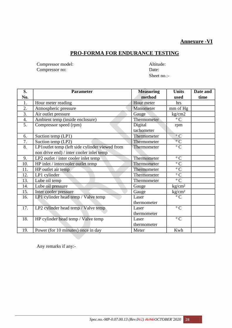
Annexure -VI
PRO-FORMA FOR ENDURANCE TESTING
Compressor model: Altitude:
Compressor no: Date:
Sheet no.:-
S. Parameter Measuring Units Date and
No. method used time
1. Hour meter reading Hour meter hrs
2. Atmospheric pressure Manometer mm of Hg
3. Air outlet pressure Gauge kg/cm2
4. Ambient temp (inside enclosure) Thermometer º C
5. Compressor speed (rpm) Digital rpm
tachometer
6. Suction temp (LP1) Thermometer º C
7. Suction temp (LP2) Thermometer º C
8. LP1outlet temp (left side cylinder viewed from Thermometer º C
non drive end) / inter cooler inlet temp
9. LP2 outlet / inter cooler inlet temp Thermometer º C
10. HP inlet / intercooler outlet temp Thermometer º C
11. HP outlet air temp Thermometer º C
12. LP1 cylinder Thermometer º C
13. Lube oil temp Thermometer º C
14. Lube oil pressure Gauge kg/cm²
15. Inter cooler pressure Gauge kg/cm²
16. LP1 cylinder head temp / Valve temp Laser º C
thermometer
17. LP2 cylinder head temp / Valve temp Laser º C
thermometer
18. HP cylinder head temp / Valve temp Laser º C
thermometer
19. Power (for 10 minutes) once in day Meter Kwh
Any remarks if any:-
Spec.no.-MP-0.07.00.13 (Rev.012) JUNEOCTOBER’2020 29
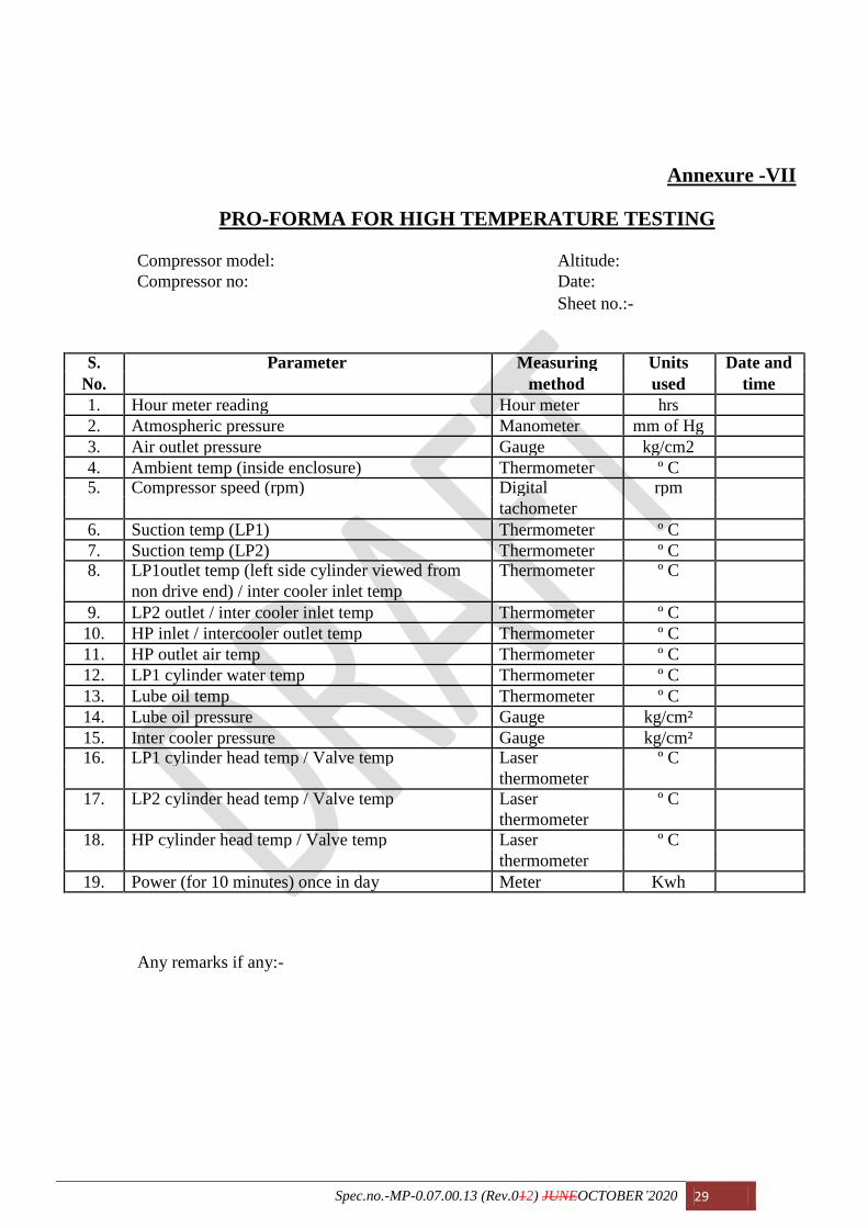
Annexure -VII
PRO-FORMA FOR HIGH TEMPERATURE TESTING
Compressor model: Altitude:
Compressor no: Date:
Sheet no.:-
S. Parameter Measuring Units Date and
No. method used time
1. Hour meter reading Hour meter hrs
2. Atmospheric pressure Manometer mm of Hg
3. Air outlet pressure Gauge kg/cm2
4. Ambient temp (inside enclosure) Thermometer º C
5. Compressor speed (rpm) Digital rpm
tachometer
6. Suction temp (LP1) Thermometer º C
7. Suction temp (LP2) Thermometer º C
8. LP1outlet temp (left side cylinder viewed from Thermometer º C
non drive end) / inter cooler inlet temp
9. LP2 outlet / inter cooler inlet temp Thermometer º C
10. HP inlet / intercooler outlet temp Thermometer º C
11. HP outlet air temp Thermometer º C
12. LP1 cylinder water temp Thermometer º C
13. Lube oil temp Thermometer º C
14. Lube oil pressure Gauge kg/cm²
15. Inter cooler pressure Gauge kg/cm²
16. LP1 cylinder head temp / Valve temp Laser º C
thermometer
17. LP2 cylinder head temp / Valve temp Laser º C
thermometer
18. HP cylinder head temp / Valve temp Laser º C
thermometer
19. Power (for 10 minutes) once in day Meter Kwh
Any remarks if any:-

Spec.no.-MP-0.07.00.13 (Rev.012) JUNEOCTOBER’2020 30
Annexure -VIII General Technical data of air compressor
01 Type Reciprocating „W‟ type, forced feed
lubrication
02 Normal working pressure 10.0 Kg/cm²
140 PSI approximately
03 Free air delivery at 1050 rpm 6390 LPM
04 Displacement volume per revolution 8.694 litres
05 Direction of rotation Anticlockwise viewed from drive end
06 Rated speed 1050 RPM
07 Speed range 350 to 1250 RPM
08 Compression stages 02 nos.
09 Low-pressure cylinders, nos. 02
Bore dia 196.875 – 196.850 mm
Total height 312.74±0.050/0.00 mm
10 High pressure cylinder, nos. 01
Bore Dia 139.00 - 139.725 mm
Total Height 312.74±0.050 / 0.00 mm
11 Piston stroke length 142.875 mm 12 Type & nos. of piston rings (On both LP 01 No. -Taper compression ring
& HP) 01 No. - Nose scraper ring
02 Nos. - Cross beveled oil control ring
13 Ring gap (For LP and HP) 0.20 - 0.45 mm (LP) 0.40 - 0.65 (HP) mm 14 Crank shaft, crank pin, dia 92.02 - 92.049 mm
Crank pin length 133.6 -133.7 mm
Bearing seat dia 190.005 – 189.976 mm
15 Low pressure piston, skirt dia 196.60 –196.64 mm Total height 00±0.05 mm
Hole for gudgeon pin dia 44.45 – 44.46 mm
16 High pressure piston, skirt dia 145.80 -145.825 mm Total height 00±0.25 mm
Hole dia for gudgeon pin/wrist dia 44.463 – 44.450 mm
17 Centre distance between big end to 349.25± 0 / 0.127 mm
small end for connecting rod
18 Power consumption at rated speed of 69 HP
1050 RPM
19 Crankcase oil capacity Minimum 14 litres
Maximum 21 litres
20 Lube oil pressure at 350 rpm 2.2 Kg/cm² minimum
at 1050 rpm 3.5 kg/cm2 maximun
21 Envelope dimension (L X B X H) 1315±5 mm X 1374±5 mm X 1015±5 mm
22 Net Weight Maximum 865±10 Kg

Spec.no.-MP-0.07.00.13 (Rev.012) JUNEOCTOBER’2020 31
Annexure -IX
General conditions of endurance test
Endurance test is a continuos test and shall be carried out by running the compressor
with compressor delivery pressure at 9.85 Kg/cm² running at load cycle maximum rated
speed. The test shall be of 400 hours duration. Normally, the interruptions are not permitted
during the testing except under following circumstances:-
1. Interruptions are permitted if any adjustment is required to be carried out during
the course of testing, which warrants stopping of compressor or drive motor.
Under these circumstances, the period of interruptions should not exceed 2
minutes. The aggregate total of such interruptions should be totalled at the end the
period of endurance testing prolonged by this aggregate amount.
2. During endurance test, maximum of 4 interruptions shall be tolerated when they
are required for attending defects in the equipments but in such case more than 20
minutes shall not be allowed to lapse between the interruptions and restart. In all
such cases consent of RDSO or its representative should be obtained before
recommencing the test. The aggregate total of such interruptions should be totaled
at the end and the period of endurance testing prolonged by this aggregate
amount. In case of more than 4 interruptions, the endurance testing should be done
afresh.
3. If endurance testing is interrupted for reasons unconnected with compressor such
as due to defect in drive motor and coupling, the test should be started within 24
hours, after the interruption will be allowed and in case the testing is interrupted
by more than one interruption, RDSO or its representatives shall decide whether
endurance test must be recommended from beginning or merely prolonged for the
period equal to that of interruption. In case of such interruption should be entered
in the column provided immediately after data prior to interruption.