specification for approvallg)lb035q02-td01.pdf · product specification 2/ 33 lb035q02 liquid...
TRANSCRIPT

Product Specification
1 / 33
LB035Q02Liquid Crystal Display
Ver 0.6 July. 09. 2007
SPECIFICATIONFOR
APPROVAL
( ) Preliminary Specification() Final Specification
Title 3.5” (320 X RGB X 240) TFT- LCD
C. S. Kyeong /G. Manager
Product Engineering Dept.LG. Philips LCD Co., Ltd
APPROVED BY DATE
REVIEWED BY
PREPARED BY
S. H. Kim / Manager
H. S. Woo / Engineer
BUYER
TD01SUFFIX
LB035Q02MODEL
LG.Philips LCD CO.,Ltd.SUPPLIER
MODEL
SIGNATURE DATE
/
/
/

Product Specification
2 / 33
LB035Q02Liquid Crystal Display
Ver 0.6 July. 09. 2007
Contents
12Touch Screen Panel Specifications5
31Precautions14
32Production Center15
28Outline Dimension 11
27Reliability Test 10
30Packing12
24Power On/Off Sequence 9
18Operation Specifications8
17Mechanical Characteristics7
14Optical Characteristics6
11Electrical Characteristics4
10Absolute Maximum Ratings3
6Interface [ Input Terminal]2
4General Description1
3Record of Revisions0
PageItemNo.
Product Specification
3 / 33
LB035Q02Liquid Crystal Display
Ver 0.6 July. 09. 2007
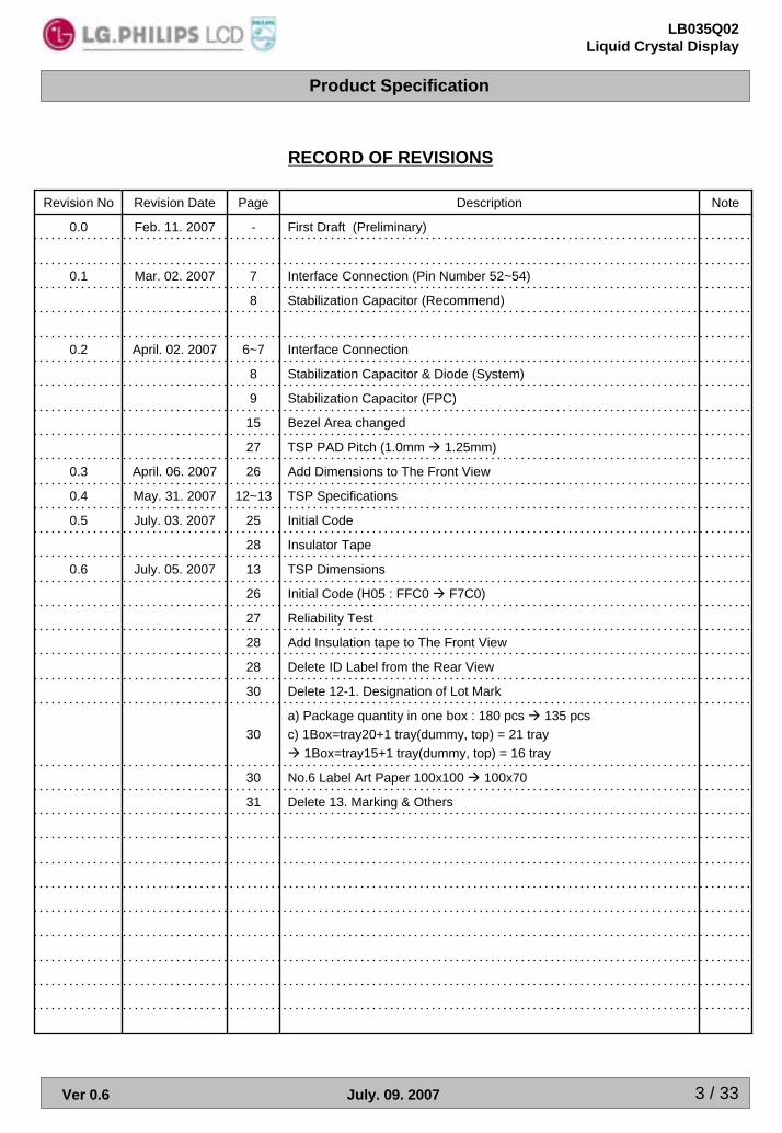
RECORD OF REVISIONS
Initial Code (H05 : FFC0 F7C0)26
TSP Dimensions13July. 05. 20070.6
Note
No.6 Label Art Paper 100x100 100x7030
Delete 13. Marking & Others 31
Delete 12-1. Designation of Lot Mark30
a) Package quantity in one box : 180 pcs 135 pcsc) 1Box=tray20+1 tray(dummy, top) = 21 tray
1Box=tray15+1 tray(dummy, top) = 16 tray30
Add Insulation tape to The Front View28
Delete ID Label from the Rear View28
Insulator Tape 28
Reliability Test 27
TSP Specifications12~13May. 31. 20070.4
Initial Code25July. 03. 20070.5
TSP PAD Pitch (1.0mm 1.25mm)27
Add Dimensions to The Front View 26April. 06. 20070.3
Stabilization Capacitor (FPC)9
Bezel Area changed15
Interface Connection 6~7April. 02. 20070.2
Stabilization Capacitor & Diode (System)8
Stabilization Capacitor (Recommend)8
Interface Connection (Pin Number 52~54)7Mar. 02. 20070.1
First Draft (Preliminary)-Feb. 11. 20070.0
DescriptionPageRevision DateRevision No

Product Specification
4 / 33
LB035Q02Liquid Crystal Display
Ver 0.6 July. 09. 2007
1. General Description
1-1. DescriptionThe LB035Q02 is a Color Active Matrix Liquid Crystal Display with a white LED backlight assembly. The matrix employs a-Si Thin Film Transistor as the active element. It is a transmissive type display operating in the normally white mode. This module is a diagonal 3.5 inch with the Landscape typed QVGA resolution.The LB035Q02 is intended to support displays. [PND(Portable Navigation Device), PMP(Portable Multimedia Player) and others]
1-2. Block Diagram
User C
onnector 60 Pin
Capacitors for Stabilization
RGB Data (24bits)
Vsync, Hsync, DOTCLK, ENABLE
V_LED(LED_A, LED_C)
Control Signal(CS, SCL, SDI, RESET)
TFT-LCD Panel(320×RGB×240)
D-IC(1Chip)Vgh, Vgl, Vcom
G2 G1
G239G240
Input Power (VCI)
Touch Screen Panel Signal(X1, Y1, X2, Y2)

Product Specification
5 / 33
LB035Q02Liquid Crystal Display
Ver 0.6 July. 09. 2007
1-3. Features
-Stripe typePixel Arrangement
colorsPseudo-16.7MDisplay Color
12 o’clock (good viewing)
6 o’clockViewing Direction
-TN / Transmissive / Normally WhiteDisplay Mode
-Digital RGB + SPI Interface Signal Interface
-41gWeight
Serial Type6 LEDsBacklight
-RGB Vertical Stripe Color Filter Array
[mm]0.073 x 0.219Dot Pitch
-320[H] x RGB x 240[V]Number of dots
[mm]70.08[H] x 52.56[V]Active Area
[mm]76.9[H] x 63.9[V] x 3.15t[D] (4.25t with Touch Panel)Outline Dimension
Diagonal3.5 inchesActive Screen Size
REMARKSPECIFICATIONPARAMETER

Product Specification
6 / 33
LB035Q02Liquid Crystal Display
Ver 0.6 July. 09. 2007
2. Interface ConnectionsThis LCD employs one interface connection for the operation of module, LED B/L and TSP.The pin configuration for the connector is shown in the table below.
(LCD Connector: FPC(60Pin 0.5mm pitch), Mating Connector: LD09T4-60NB(LS Cable) or equivalent
IGG1, Green DataPD927
IGG2, Green DataPD1028
IGG3, Green DataPD1129
IGG4, Green DataPD1230
IGG5, Green DataPD1331
IGG6, Green DataPD1432
IBB7, Blue Data [MSB]PD725
IBB6, Blue DataPD624
IGG0, Green Data [LSB]PD826
I
I
I
I
I
I
I
I
I
I
I
I
-
O
O
-
I
I
I
I
I
I
I
I
I/O Remark
GG7, Green Data [MSB]PD1533
BB5, Blue DataPD523
BB4, Blue DataPD422
BB3, Blue DataPD321
BB2, Blue DataPD220
BB1, Blue DataPD119
BB0, Blue Data [LSB]PD018
Serial Data InputSDI17
Serial Clock LineSCL16
Chip SelectCS15
System ResetRESET14
GroundGND13
No ConnectNC12
Gate High Voltage, Stabilization CapacitorVGH11
Gate Low Voltage, Stabilization Cap. + DiodeVGL10
No ConnectNC9
GroundGND8
Touch Panel Position YY27
Touch Panel Position XX26
Touch Panel Position YY15
Touch Panel Position XX14
GroundGND3
LED_AnodeLED_A2
LED_CathodeLED_C1
DescriptionSymbolPin

Product Specification
7 / 33
LB035Q02Liquid Crystal Display
Ver 0.6 July. 09. 2007
OStabilization Capacitor (P)CXP58
OStabilization Capacitor (N)CXN57
OStabilization Capacitor (N)CN56
OStabilization CapacitorVCOMH55
OStabilization Cap. + DiodeVCIX2(J)54
OStabilization Capacitor (P)CP59
I
O
O
-
O
O
I
-
I
I
I
I
I
I
I
I
I
I
I
I
I
I/O Remark
GroundGND60
Stabilization CapacitorVCOML53
Stabilization CapacitorVDD52
No ConnectNC51
Stabilization CapacitorVLCD6350
Stabilization CapacitorVCIM49
PowerVCI48
No ConnectNC47
PowerVCI46
Vertical Sync SignalVSYNC45
Horizontal Sync SignalHSYNC44
Data EnableENABLE43
Dot clockDOTCLK42
RR7, Red Data [MSB]PD2341
RR6, Red DataPD2240
RR5, Red DataPD2139
RR4, Red DataPD2038
RR3, Red DataPD1937
RR2, Red DataPD1836
RR1, Red DataPD1735
RR0, Red Data [LSB]PD1634
DescriptionSymbolPin

Product Specification
8 / 33
LB035Q02Liquid Crystal Display
Ver 0.6 July. 09. 2007
VCIM
VLCD63
VDD
CP
2-1. System
0.1uF, 6.3V
2.2uF, 6.3V
1uF, 6.3V
2.2uF, 6.3V
VCIX2
CN
CXP0.1uF, 6.3V
CXN
VCOMH1uF, 6.3V
VCOML1uF, 6.3V
VGL
VGH
2.2uF, 16V
2.2uF, 16V
BAT43WS
VCI3.3V
4.7uF, 6.3V
BAT43WS

Product Specification
9 / 33
LB035Q02Liquid Crystal Display
Ver 0.6 July. 09. 2007
2-2. FPC
C1PC1N
C2PC2N
0.1uF, 6.3V
0.1uF, 6.3V
C3PC3N
CYPCYN
0.1uF, 6.3V
0.1uF, 6.3V

Product Specification
10 / 33
LB035Q02Liquid Crystal Display
Ver 0.6 July. 09. 2007
3. Absolute Maximum Ratings
If used the beyond absolute maximum ratings, this device can permanently be damaged.It is strongly recommended to use this device at a condition for normal operation.
[Note 3-2]80-30-TSTStorage Temperature
[Note 3-2] 70-20-TOPOperating Temperature
REMARKUNITMAX.MIN.CONDITIONSYMBOLPARAMETER
HOP
If
VCI
[Note 3-1]mA25-Ta=25LED Forward Current
-V5.0-0.3Ta=25Power Supply Voltage
[Note 3-2]%RH955-Humidity
[Note 3-1] Applies for each LED individually[Note 3-2] Humidity: 95% RH Max, no condensation > 40

Product Specification
11 / 33
LB035Q02Liquid Crystal Display
Ver 0.6 July. 09. 2007
4. Electrical Characteristics
CTa°= 254-1. TFT LCD Module
REMARKUNITMAX.TYP.MIN.SYMBOLPARAMETER
Hz70-fFRAME Frame Frequency
MHz106.5-DOTCLKDot Clock
See. 7-2-2ns--100SCLSerial Clock
uA3.0--1.0IILInput Leakage Current
uA4.5-3.0IOLOutput Leakage Current
V-11-9-7VGLGate Off Voltage
V151310VGHGate On Voltage
V3.63.32.5VCIPower Supply Voltage
4-2. Backlight Unit CTa°= 25
REMARKUNITMAX.TYP.MIN.SYMBOLPARAMETER
mW-400-PBLPower Consumption
[Note4-1]mA-20-IfLED forward Current
[Note4-1] The permissible forward current of LED vary with environmental temperature.

Product Specification
12 / 33
LB035Q02Liquid Crystal Display
Ver 0.6 July. 09. 2007
5. Touch Screen Panel Specifications5-1. TSP Design Guide
- Use a cushion material between the touch panel and the bezel.- Do not overlap and contact between the Case/Bezel and the TSP active area
[Note]
Area(a): Active area
The active area is guaranteed the position data detectable precision, operation force and other operations.It is strongly recommended to place the operation button or menu keys within the active area.
Area(b): Operation non-guaranteed area
This area does not guarantee a touch panel operation and its function. When this area is pressed, touchpanel shows degradation of its performance and durability such as a pen sliding durability.
Area(c): Pressing prohibition areaThe area which forbids pressing, because an excessive load is applied to a transparent electrode(ITO)and a serious damage is given to a touch panel function by pressing
Area(d): Non-Active areaT rea does not activate even if pressedhe a

Product Specification
13 / 33
LB035Q02Liquid Crystal Display
Ver 0.6 July. 09. 2007
5-2. TSP Dimensions

Product Specification
14 / 33
LB035Q02Liquid Crystal Display
Ver 0.6 July. 09. 2007
CTa°= 25( )5-3. Electrical Characteristics
X-axisΩ900-200
Y-axisΩ900-200Terminal Resistance
Analog X & Y Directions%1.5-1.5Linearity
DCV7--Voltage
DC 25V--25Insulation Resistance
REMARKUNITMAX.TYP.MIN.PARAMETER
%-80-Transparency
ms10--Chattering
5-4. Mechanical & Reliability Characteristics
[Note]CharactersWrite
100,000Durability
(Surface scratching)
R0.8mm polyacetal Pen or Fingerg100--Activation force
Judgment ref.JIS-K5600H--3Surface hardness
[Note]Touches1,000,000Durability
(Surface pitting)
REMARKUNITMAX.TYP.MIN.PARAMETER
[Note] (1) Measurement for Surface area
- Force : 250gf- Speed : 60m/sec- Stylus : R0.8 polyacetal tip
(2) Pit 1,000,000 times on the Film with a R8.0 silicon rubber- Force : 250gf- Speed : 2times/sec

Product Specification
15 / 33
LB035Q02Liquid Crystal Display
Ver 0.6 July. 09. 2007
6. Optical Characteristics
6-1. TFT LCD Module CTa°= 25
Luminance Uniformity
Response Time
Viewing Angle
White colorChromaticity
Contrast Ratio
Luminance(with Touch Panel)
PARAMETER
[Note5-5]-1.401.20-IBL =20mAU
Falling[Note5-4]PR-880
msec3025-Rising
-60-
-50-Ver.
-65- [Note5-2][Note5-3]PR-880
Degrees
-65-
CR > 10
Hor.
-0.380.330.28Wy
[Note5-1]PR-650
-0.360.310.26IBL =20mA
Wx
[Note5-2]--400-Center PointCR
[Note5-1]-300-IBL =20mAY
REMARKUNITMAX.TYP.MIN.CONDITIONSYMBOL
cd/m2
Lθ
Rθ
Uθ
Dθ
fr TT + °= 0θ
Measurement condition : Refer to the below “Test Equipment Set Up” and next two pages
[Test Equipment Set Up]
Photo detectorField = 1 °
Center
LCD Module
Optical Stage(x,y)
; Pritchard 880 for Luminance,PR650 for Chromaticity or equivalent
500mm
Measuring Condition ;-Measuring surroundings : Dark Room-Measuring temperature : Ta=25-Adjust operating voltage to get optimum contrast at the center of the display.-Measured value at the center point of LCD panel after more than 10 minutes while backlight turning on.

Product Specification
16 / 33
LB035Q02Liquid Crystal Display
Ver 0.6 July. 09. 2007
[Note 6-1]
Measured on the center area of the panel by PHOTO RESEARCH photometer PR-880&PR650 or Equivalent
[Note 6-2]
Contrast ratio is defined as follows ;
Contrast Ratio(CR) =Photo detector output with LCD being “white”
Photo detector output with LCD being “black”
[Note 6-3]
Viewing angle range is defined as follows [PR-880];
<Dimension of viewing angle range>
z’ yd
xr
φ
θ= 0˚zφ= 90˚
(12:00) yu
θ
φ= 0˚(3:00)
φ = 180˚(9:00)
xl
φ= 270˚(6:00)
TFT LCDMODULE

Product Specification
17 / 33
LB035Q02Liquid Crystal Display
Ver 0.6 July. 09. 2007
[Note 6-4]
Response time is obtained by measuring the transition time of photo detector output, when input signals are applied so as to make the area “black” to and from “white”.
0%
10%
90%
White White
Black
Time
Pho
to d
etec
tor O
utpu
t
τr τd
[Note 6-5]
①
HA
B
V
A : H/4 mmB : V/4 mmH : 70.08 mmV : 52.56 mmH×V: Active Area
② ③ ④
⑥
⑧⑦
⑤
⑨Active Area
Luminance Uniformity= Maximum of 9points (①~⑨) / Minimum of 9points (①~⑨)Luminance Uniformity(%) = Minimum of 9points (①~⑨) / Maximum of 9points (①~⑨) x 100

Product Specification
18 / 33
LB035Q02Liquid Crystal Display
Ver 0.6 July. 09. 2007
7. Mechanical Characteristics
45 (Max.)g41 (Typ.)Weight
Clear Hard Coating(3H) TreatmentSurface Treatment
mm
mm
mm
mm
mm
UNIT
55.26
72.48
3.15 (without TSP)4.25 (with TSP)
63.9
76.9
Height
WidthBezel Area
Depth
Height
-
Width
Outline Dimension
REMARKSPECIFICATIONPARAMETER

Product Specification
19 / 33
LB035Q02Liquid Crystal Display
Ver 0.6 July. 09. 2007
8. Operation Specifications
8-1. RGB Data Interface
8-1-1. RGB Data Interface Timing Characteristics
VSYNC
HSYNC
DOTCLK
PixelData
tvSYS tvSYH
thSYS thSYH
tDOTCLK
thV
tCKL tCKH
tDS tDH
10
10
10
10
10
10
30
15
15
33.3
Min.
8 bit Interface
-
-
-
-
-
-
-
-
-
-
Max.
ns
ns
ns
ns
ns
ns
ns
ns
ns
ns
Unit
-
-
-
-
-
-
-
-
-
-
Max.
12
12
20
20
20
20
10
50
50
100
Min.
24bit Interface
tDHData Hold Time
tDSData Setup Time
thSYHHorizontal Sync Hold Time
thSYSHorizontal Sync Setup Time
tvSYHVertical Sync Hold Time
tvSYSVertical Sync Setup Time
tDOTCLKDOTCLK Frequency
tCKHDOTCLK High Period
tCKLDOTCLK Low Period
tDOTCLKDOTCLK Period
SYMBOLPARAMETER
[Note] External clock source must be provided to LCM.The LCM will not operate if absent of the clocking signal.

Product Specification
20 / 33
LB035Q02Liquid Crystal Display
Ver 0.6 July. 09. 2007
8-1-2. Data Format for 24 bit RGB Data Interface
Input D23 D22 D21 D20 D18D19 D17 D16 DD15 14 D12D13 D11 D10 D9 D8 D7 D6 D5 D4 D3 D2 D1 D0
GG2GG3RGB Arrangement RR7 RR6 RR5 RR4 RR3 RR2 RR1 RR0 GG7 GG6 GG4GG5 GG0GG1 BBB7 B6 BB5 BBB4 B3 BB2 BB1 BB0
8-1-3. Data Format for 18 bit RGB Data Interface
D11 D10 D9Input D23 D22 D21 D20 D18D19 D17 D16 DD15 14 D12D13 D8 D7 D6 D5 D4 D3 D2 D1 D0
RGB Arrangement
RR7 RR6 RR5 RR4 RR3 RR2 RR1 RR0 GG7 GG6 GG4 GG2 GG0 BB6GG5 GG3 GG1 BB7 BB5 BB3BB4 BB2 BB1 BB0
[Note] LSB 2bits are connected to VSS or floating.
8-1-4. Data Format for 8 bit RGB Data Interface
D11 D10 D9Input D23 D22 D21 D20 D18D19 D17 D16 DD15 14 D12D13 D8 D7 D6 D5 D4 D3 D2 D1 D0
RGB Arrangement RR7 RR6 RR5 RR4 RR3 RR2 RR1 RR0 GG7 GG6 GG4 GG2 GG0 BB6GG5 GG3 GG1 BB7 BB5 BB3BB4 BB2 BB1 BB0
[Note] For 8 bit interface, only RR[7:0] are used.For unused pins, please connect to GND or floating.

Product Specification
21 / 33
LB035Q02Liquid Crystal Display
Ver 0.6 July. 09. 2007
8-1-3. 24 Bit RGB Interface Timing
8-1-3-1. Sync Mode
a) Horizontal Data Transaction Timing
Hcycle=408
DOTCLK
HSYNC
tHBP=68 Hdisp=320 tHFP=20
PixelData
D0 D1 D319 D3Dummy Dummy20
b) Vertictal Data Transaction Timing
Vdisp=240Lines tvfp=4
HSYNC
Vcycle=262Lines
tVBP=18
VSYNC
240
4
18
60
204
60
14.9
51.3
19.5
8bit
240
4
18
20
68
60
14.9
154
6.5
24bit
Typ.
LinestDISPVertical Display Area
LinestVFPVertical Front porch
LinestVBPVertical Back porch
tDOTCLK tHFPHorizontal Front porch
tDOTCLKtHBPHorizontal Back porch
HzfVVertical Frequency(Refresh)
kHzfHHorizontal Frequency(Line)
nstDOTCLKDOTCLK Period
MHzfDOTCLKDOTCLK Frequency
UnitSYMBOLPARAMETER
[Note] The rising edge of DOTCLK is used to fetch display data PD bus.The Delay amount of the source output must be larger than the Hsync Low Pulse Width.

Product Specification
22 / 33
LB035Q02Liquid Crystal Display
Ver 0.6 July. 09. 2007
8-1-3. 24 Bit RGB Interface Timing
8-1-3-2. DE Mode
319 320
3H >2H
1 Horizontal Period
1 Period (1 Frame)
Dummy Enable240H
DOTCLK
DEN
DATA[23:0]
DOTCLK
320 dotclk 31~80 dotclk
DEN
1 2 3 4 1DATA[23:0]
Valid Data Transfer Area

Product Specification
23 / 33
LB035Q02Liquid Crystal Display
Ver 0.6 July. 09. 2007
8-2. Serial Peripheral Interface
8-2-1. Serial Peripheral Interface Timing
Transfer starts Transfer ends
CSB
1 2 3 4 5 6 7 8 9 10 11 12 13 14 15 16 17 18 19 20 21 22 23 24
SCL
MSB LSB
RS RW DB15
DB14
DB13
DB12
DB11
DB10
DB9
DB8
DB7
DB6
DB5
DB4
DB3
DB2
DB1
DB0
SDI 0 1 1 1 00
Device ID Index register setting Instruction
[Note] RS=“0” [Index], RS=“1” [Instruction]

Product Specification
24 / 33
LB035Q02Liquid Crystal Display
Ver 0.6 July. 09. 2007
8-2-2. Clock Synchronized Serial Mode Characteristics
CSB
SCL
SDI
Transfer starts Transfer ends
VIL
VIH
VIL VIL VIL VIL
VIL VIL
VIHVIH
VIH VIHVIH VIH
tCSS
tSIDS tSIDH
tscyc
tSCHW/tSCHR
tSCLW/tSCLR
tR tF tCSH
-30tSIDHSerial Input Data Hold Time
-30tSIDSSerial Input Data Setup Time
-50tCSHChip Select Hold Time
-20tCSSChip Select Setup Time
-50tSCLRPulse Width Low For Read
-30tSCLWPulse Width Low For Write
-50tSCHRPulse Width High For Read
-30tSCHWPulse Width High For Write
2-tR,tFSerial Clock Rise/Fall Time
ns
-100tscycSerial Clock Cycle Time
UNITMAX.MIN.SYMBOLPARAMETER

Product Specification
25 / 33
LB035Q02Liquid Crystal Display
Ver 0.6 July. 09. 2007
9. Power On/Off Sequence
9-1. Power On Sequence
VDD
VCI
RESB
SHUT
DOTCLK
HSYNC
VSYNC
DisplayHighVoltage
Display
>1ns
tp-shut
tclk-shut
1st 10th
Tshut-lcd
Tshut-on
>1ns
ON
-
-
-
1
1
MIN.
166
-
-
-
-
Typ.
ms-
frame10
tshut-on
Falling edge of SHUT to display start-1 line : 408 clk- 1 frame : 262 line-DOTCLK = 6.5MHz
ms128tshut-lcdFalling edge of SHUT to LCD power on
clk-tclk-shutDOTCLK
us-tp-shutVDD on to falling edge of SHUT
UnitsMAX.SYMBOLCharacteristics
[Note] It is necessary to input DOTCLK before the falling edge of SHUT.Display starts at 10th falling edge of VSYNC after the falling edge of SHUT.
Product Specification
26 / 33
LB035Q02Liquid Crystal Display
Ver 0.6 July. 09. 2007
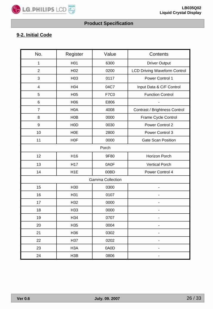
9-2. Initial Code
Porch
Gamma Collection
Horizon Porch9F80H1612
Gate Scan Position0000H0F11
Power Control 32800H0E10
Power Control 20030H0D9
Frame Cycle Control0000H0B8
Contrast / Brightness Control4008H0A7
-E806H066
Function ControlF7C0H055
Input Data & C/F Control04C7H044
Power Control 10117H033
LCD Driving Waveform Control0200H022
Driver Output6300H011
-0000H3318
-0000H3217
-0107H3116
-0300H3015
Power Control 400BDH1E14
Vertical Porch0A0FH1713
-0004H3520
-0707H3419
-0202H3722
-0302H3621
-0A0DH3A23
-0806H3B24
ContentsValueRegisterNo.

Product Specification
27 / 33
LB035Q02Liquid Crystal Display
Ver 0.6 July. 09. 2007
9-3. Power Off Sequence
VDD
VCI
RESB
SHUT
DOTCLK
HSYNC
VSYNC
DisplayHighVoltage
Display
>1ns
1st 2nd
Tshut-off
Toff-vdd
OFFON
>1ns
1
33.4
2
MIN.
-
-
-
Typ.
us-tshut-vddInput-signal-off to VDD off
ms-
frame-
tshut-off
Rising edge of SHUT to display off- 1 line : 408 clk-1 frame : 262 line- DOTCLK =6.5MHz
UnitsMAX.SYMBOLCharacteristics
[Note] DOTCLK must be maintained at lease 2 frames after the rising edge of SHUT.Display become off at the 2nd falling edge of VSYNC after the falling edge of SHUT.If RESET signal is necessary for power down, provide it after the 2-frame-cycle of the SHUT period.

Product Specification
28 / 33
LB035Q02Liquid Crystal Display
Ver 0.6 July. 09. 2007
10. Reliability Test
-30(0.5h) ~ 80(0.5h) / 10cycle
Ta = 60 90%RH 240h
Ta = -20 240h
Ta = 70 240h
Ta = -30 240h
Ta = 80 240h
CONDITION
-
-
-
-
-
-
REMARK
High Temperature and HighHumidity Operation Test
5
Thermal Shock Test6
Low Temperature Operation Test4
High Temperature Operation Test3
Low Temperature Storage Test2
High Temperature Storage Test1
TEST ITEMSNO
[Note]Ta= Ambient Temperature
In the standard condition, there shall be no practical problems that may affect the display function.
Result Evaluation Criteria
TFT- LCD Module should be at room temperature for 2 hours when the display quality test is over. There should be no particular change which might affect the practical display function and the display quality test should be conducted under normal operating condition.

Product Specification
29 / 33
LB035Q02Liquid Crystal Display
Ver 0.6 July. 09. 2007
11. Outline Dimension
11-1. Front View
11-2. Rear View

Product Specification
30 / 33
LB035Q02Liquid Crystal Display
Ver 0.6 July. 09. 2007
11-3. FPC (Front View)

Product Specification
31 / 33
LB035Q02Liquid Crystal Display
Ver 0.6 July. 09. 2007
12. Packing
12-1. Packing Form
a) Package quantity in one box : 135 pcsb) Box Size : 475mm × 348mm × 210mmc) 1Box = tray 15 + 1 tray(dummy , top) = 16 tray
PE 560x 830Bag3
SWR4 378x324x112Box4
OPP 70MMx300mTape5
Art Paper 100x70Label6
PET(0.8t)Packing, Tray2
Module1
MaterialDescriptionNO.

Product Specification
32 / 33
LB035Q02Liquid Crystal Display
Ver 0.6 July. 09. 2007
14. Precautions Please pay attention to the following when you use this TFT LCD module.
14-1. Mounting Precautions
<1> You may mount a module using four corner sides. <2> You should consider the mounting structure so that uneven force(ex. Twisted stress) is not aplied
to the module.And the case on which a module is mounted should have sufficient strength so that external forceis not transmitted directly to the module.
<3> Please attach a transparent protective plate to the surface in order to protect the polarizer.Transparent protective plate should have sufficient strength in order to the resist external force.
<4> You should adopt radiation structure to satisfy the temperature specification.<5> Acetic acid type and chlorine type materials for the cover case are not desirable because the
formergenerates corrosive gas of attacking the polarizer at high temperature and the latter causes circuitbreak by electro-chemical reaction.
<6> Do not touch, push or rub the exposed polarizers with glass, tweezers or anything harder than HBpencil lead. And please do not rub with dust clothes with chemical treatment.Do not touch the surface of polarizer for bare hand or greasy cloth.(Some cosmetics deterioratethe polarizer.)
<7> When the surface becomes dusty, please wipe gently with absorbent cotton or other soft materialslike chamois soaks with petroleum benzine. Normal-hexane is recommended for cleaning theadhesives used to attach front / rear polarizers. Do not use acetone and toluene because they cause chemical damage to the polarizer.
<7> Wipe off saliva or water drops as soon as possible. Their long time contact with polarizer causesdeformations and color fading.
<8> Do not open the case because inside circuits do not have sufficient strength. <9> The metal case of a module should be contacted to electrical ground of your system.
14-2. Operating Precautions
<1> The spike noise causes the disoperation of circuits. It should be lower than following voltage V=±200mV(Over and under shoot voltage)
<2> Response time depends on the temperature.(In lower temperature, it becomes longer.)<3> Brightness depends on the temperature. (In lower temperature, it becomes lower.)
And in lower temperature, response time(required time that brightness is stable after turned on)becomes longer.
<4> Be careful for condensation at sudden temperature change. Condensation makes damage topolarizer or electrical contacted parts. And after fading condensation, smear or spot will occur.
<5> When fixed patterns are displayed for a long time, remnant image is likely to occur.<6> Module has high frequency circuits. Sufficient suppression to the electromagnetic interference
shall be done by system manufacturers. Grounding and shielding methods may be important tominimized the interference.

Product Specification
33 / 33
LB035Q02Liquid Crystal Display
Ver 0.6 July. 09. 2007
14-3. Electrostatic Discharge Control
Since a module is composed of electronic circuits, it is not strong to electrostatic discharge. Make certain that treatment persons are connected to ground through wrist band etc. And don’t touch interface pin directly.
14-4. Precautions For Strong Light ExposureStrong light exposure causes degradation of polarizer and color filter.
14-5. Storage
When storing modules as spares for a long time, the following precautions are necessary.<1> Store them in a dark place. Do not expose the module to sunlight or fluorescent light. Keep the
temperature between 5°C and 35°C at normal humidity.<2> The polarizer surface should not come in contact with any other object.<3> The warranty for storage of the color TFT-LCD module shall be in compliance
with the Incoming Inspection standard.
14-6. Handling Precautions For Protection Film<1> When the protection film is peeled off, static electricity is generated between the film and polarizer.
This should be peeled off slowly and carefully by people who are electrically grounded and with wellion-blown equipment or in such a condition, etc.
<2> The protection film is attached to the polarizer with a small amount of glue. If some stress is appliedto rub the protection film against the polarizer during the time you peel off the film, the glue is apt toremain on the polarizer.Please carefully peel off the protection film without rubbing it against the polarizer.
<3> When the module with protection film attached is stored for a long time, sometimes there remains avery small amount of glue still on the polarizer after the protection film is peeled off.
<4> You can remove the glue easily. When the glue remains on the polarizer surface or its vestige isrecognized, please wipe them off with absorbent cotton waste or other soft material like chamoissoaked with normal-hexane.
15. Production Center
<1> Panel : LG Philips LCD (Gumi, Korea)<2> Module Assembly : LPL NJ (Nanjing, China)<3> Shipping Place : LG Philips LCD(Gumi, Korea)