specification & design of real-time systemspages.erau.edu/~kornecka/realtimelab/blue/02...
TRANSCRIPT
Specification & Design of Real-time Systems
FA_07_SE_545: ERAU TEAM BLUE
Software Requirements Specification Automatic Production Environment
Christopher Griffis
Steve Harvey
Leonardo Matos
Jason McGuire
Sean Pfeifer
Caylyne Shelton

Software Requirements Specification: Automatic Production Environment Version: 2.0
FA_07_SE_545: ERAU TEAM BLUE Date: 10/24/07
ii
Document Information Category Information
Document ID Software Requirements Specification: Automatic Production Environment
Document Owner FA_07_SE_545: ERAU TEAM BLUE
Revision History Date Version Description Author
9/20/07 0.1 Initial document template Christopher Griffis
10/05/07 0.2 Template alterations Christopher Griffis
10/07/07 0.3 System requirements
Hardware Requirements
User Interface Requirements
Specific Requirements
Sean Pfeifer
Jason McGuire
Jason McGuire
Christopher Griffis
10/08/07 0.9 SRS Draft release for peer review Christopher Griffis
10/10/07 1.0 SRS version 1 release TEAM BLUE
10/24/07 2.0 SRS version 2 release after inspection TEAM BLUE
Document Approvals Role Name Signature Date
Project Sponsor A. Kornecki 10/24/07
Project Review Group FA_07_SE_545 10/24/07
Project Lead Christopher Griffis 10/24/07
Requirements Lead Sean Pfeifer 10/24/07
Hardware Lead Jason McGuire 10/24/07
Design Lead Caylyne Shelton 10/24/07
Programming Lead Steve Harvey 10/24/07
Quality Manager Leonardo Matos 10/24/07
Preface
This Software Requirements Specification loosely follows the layout suggested by IEEE Std. 830-1998, “IEEE
Recommended Practice for Software Requirements Specifications.” However, certain liberties have been taken with
the compliance of the format suggested in IEEE Std. 830-1998; the material provided herein is presented to best fit
the needs of Software Requirements Specification as a project communication tool and reference document.
Software Requirements Specification: Automatic Production Environment Version: 2.0
FA_07_SE_545: ERAU TEAM BLUE Date: 10/24/07
iii
Table of Contents
TITLE PAGE .................................................................................................................................................................ii
SIGNATURE PAGE......................................................................................................................................................ii
CHANGE HISTORY.....................................................................................................................................................ii
PREFACE ......................................................................................................................................................................ii
1. INTRODUCTION ................................................................................................................................................1
1.1 PURPOSE.....................................................................................................................................................1 1.2 DOCUMENT PURPOSE .................................................................................................................................1 1.3 STAKEHOLDERS..........................................................................................................................................1 1.4 SCOPE.........................................................................................................................................................1 1.5 DEFINITIONS, ACRONYMS, AND ABBREVIATIONS .......................................................................................1 1.6 REFERENCES...............................................................................................................................................3 1.7 OVERVIEW..................................................................................................................................................3
2. OVERALL DESCRIPTION.................................................................................................................................3
2.1 PRODUCT PERSPECTIVE ..............................................................................................................................3
2.1.1 Description.....................................................................................................................................3 2.1.2 Models ...........................................................................................................................................3 2.1.3 System Interfaces...........................................................................................................................5 2.1.4 User Interfaces ...............................................................................................................................6 2.1.5 Hardware Interfaces .......................................................................................................................6 2.1.6 Software Interfaces ........................................................................................................................6 2.1.7 Communications Interfaces ...........................................................................................................6
2.2 PRODUCT FUNCTIONS.................................................................................................................................6 2.3 USER CHARACTERISTICS ............................................................................................................................6
2.3.1 Local Operator ...............................................................................................................................6 2.3.2 Web Operator.................................................................................................................................6
2.4 CONSTRAINTS.............................................................................................................................................6
2.4.1 Development Constraints...............................................................................................................6 2.4.2 Standards Compliance ...................................................................................................................7
2.5 ASSUMPTIONS AND DEPENDENCIES............................................................................................................7
3. SPECIFIC REQUIREMENTS..............................................................................................................................7
3.1 SYSTEM REQUIREMENTS ............................................................................................................................7
3.1.1 System Functional Requirements...................................................................................................7 3.1.2 System Interface Requirements .....................................................................................................8 3.1.3 Timing Constraints ........................................................................................................................8
3.2 HARDWARE REQUIREMENTS ......................................................................................................................8
3.2.1 Hardware Constraints ....................................................................................................................8 3.2.2 Hardware Nonfunctional Requirements.........................................................................................8 3.2.3 Hardware Functional Requirements...............................................................................................9
3.3 EXTERNAL INTERFACE REQUIREMENTS......................................................................................................9
3.3.1 User Interfaces ...............................................................................................................................9 3.3.2 Communications Interfaces .........................................................................................................10
Software Requirements Specification: Automatic Production Environment Version: 2.0
FA_07_SE_545: ERAU TEAM BLUE Date: 10/24/07
iv
3.4 SOFTWARE REQUIREMENTS......................................................................................................................10
3.4.1 Functional Requirement: PROC1 ................................................................................................12 3.4.2 Functional Requirement: PROC2 ................................................................................................13 3.4.3 Functional Requirement: PROC3 ................................................................................................15 3.4.4 Functional Requirement: PROC4 ................................................................................................16 3.4.5 Functional Requirement: PROC5 ................................................................................................17 3.4.6 System Modes..............................................................................................................................18
3.5 PERFORMANCE REQUIREMENTS ...............................................................................................................21 3.6 DESIGN CONSTRAINTS..............................................................................................................................21 3.7 SOFTWARE SYSTEM ATTRIBUTES .............................................................................................................21 3.8 OTHER REQUIREMENTS ............................................................................................................................21
4. APPENDICES ....................................................................................................................................................21
4.1 DATA DICTIONARY...................................................................................................................................21 4.2 USE CASES ...............................................................................................................................................23
4.2.1 Use Case Diagram .......................................................................................................................23 4.2.2 Use Case Scenarios ......................................................................................................................24 4.2.3 Sequence Diagrams......................................................................................................................30
4.3 REQUIREMENTS TRACEABILITY MATRIX..................................................................................................33
Software Requirements Specification: Automatic Production Environment Version: 2.0
FA_07_SE_545: ERAU TEAM BLUE Date: 10/24/07
v
Table of Figures
FIGURE 1: AUTOMATIC PRODUCTION ENVIRONMENT - LOGICAL COMPONENT LAYOUT ...................4
FIGURE 2: APE SYSTEM CONTEXT DIAGRAM....................................................................................................4
FIGURE 3: APE ENTITY-RELATIONSHIP DIAGRAM...........................................................................................5
FIGURE 4: DATA FLOW DIAGRAM FOR ALL SOFTWARE MODES................................................................11
FIGURE 5: APE STATE CHART ..............................................................................................................................18
FIGURE 6: DATA FLOW DIAGRAM FOR THE AUTO CONTROL MODE ........................................................19
FIGURE 7: DATA FLOW DIAGRAM FOR THE USER CONTROL MODE .........................................................20
FIGURE 8: APE TIMING DIAGRAM FOR 100MS HYPER-PERIOD....................................................................21
FIGURE 9: APE USE CASE DIAGRAM ..................................................................................................................23
FIGURE 10: SEQUENCE DIAGRAM FOR UC1......................................................................................................30
FIGURE 11: SEQUENCE DIAGRAM FOR UC2......................................................................................................30
FIGURE 12: SEQUENCE DIAGRAM FOR UC3......................................................................................................31
FIGURE 13: SEQUENCE DIAGRAM FOR UC4......................................................................................................31
FIGURE 14: SEQUENCE DIAGRAM FOR UC5......................................................................................................31
FIGURE 15: SEQUENCE DIAGRAM FOR UC6......................................................................................................32
FIGURE 16: APE REQUIREMENTS TRACEABILITY MATRIX, PART 1...........................................................33
FIGURE 17: APE REQUIREMENTS TRACEABILITY MATRIX, PART 2...........................................................34
Software Requirements Specification: Automatic Production Environment Version: 2.0
FA_07_SE_545: ERAU TEAM BLUE Date: 10/24/07
vi
List of Tables
TABLE 1: PROCESS SPECIFICATION FOR [PROC1]...........................................................................................12
TABLE 2: PROCESS SPECIFICATION FOR [PROC2]...........................................................................................13
TABLE 3: RESPONSE LOOKUP TABLE FOR [PROC2] AUTOCONTROL() ......................................................14
TABLE 4: PROCESS SPECIFICATION FOR [PROC3]...........................................................................................15
TABLE 5: PROCESS SPECIFICATION FOR [PROC4]...........................................................................................16
TABLE 6: PROCESS SPECIFICATION FOR [PROC5]...........................................................................................17
TABLE 7: UC1: BELT1 MOVES PACKAGE...........................................................................................................24
TABLE 8: UC2: SCANNER SCANS PACKAGE .....................................................................................................25
TABLE 9: UC3: PUSHER PUSHES PACKAGE.......................................................................................................26
TABLE 10: UC4: BELT2 MOVES PACKAGE .........................................................................................................27
TABLE 11: UC5: USER VIEWS STATUS................................................................................................................28
TABLE 12: UC6: USER TAKES CONTROL............................................................................................................29
Software Requirements Specification: Automatic Production Environment Version: 2.0
FA_07_SE_545: ERAU TEAM BLUE Date: 10/24/07
Page 1
Software Requirements Specification
Automatic Production Environment
1. Introduction
SE545: Specification and Design of Real-time Systems is a graduate level software engineering course at Embry-
Riddle Aeronautical University. As of the fall of 2007, this course requires the production of “software artifacts
representing the core operational part of a selected system. [1]” The project Automatic Production Environment
aims to fulfill these course requirements through a well defined real-time approach to software development.
1.1 Purpose
The Automatic Production Environment is an industry control system based on Fischertechnik blocks, imitating
operation of airport luggage conveyor belt system with a scanning machine. It will simulate the ability of a real-time
software based system to transfer a payload/luggage item down a conveyer belt and “scan” it (simulating a security
scan). A pneumatic/motor driven pushing device will then transfer the luggage to a second belt, which will carry the
luggage to a specified final point. The system will have the ability to meet specified transition, motion, and timing
requirements provided in the user needs document. Unlike typical academic software projects, this project looks at
the problem from a system perspective, and will serve to emphasize real-time software principles.
1.2 Document Purpose
This document is to act as a project communication tool and reference document, outlining the system, hardware,
interface, and software requirements intended for implementation.
1.3 Stakeholders
• Sponsor: Dr. Andrew J. Kornecki, Embry-Riddle Aeronautical University
• Members of TEAM BLUE
o Christopher Griffis (Project Lead)
o Steve Harvey (Programming Lead)
o Leo Matos (Quality Lead)
o Jason McGuire (Hardware Lead)
o Sean Pfeifer (Requirements Lead)
o Caylyne Shelton (Design Lead)
1.4 Scope
The requirements, diagrams, definitions, and related material in this document address how the system can be
composed from the provided hardware parts and run with software following a set of specified characteristics. It
makes no assertions or specifications on the details, mechanics, or operations of the individual hardware
(Fischertechnik) parts, but only how their composition should behave as a system. Many of the tools, interfaces,
protocols, and software programs used in the development of the APE are simply mentioned by name but no
specifics are given beyond that. Responses to certain system behavioral deviations are deferred to the design phase;
their declarations are considered outside the scope of this document.
1.5 Definitions, Acronyms, and Abbreviations
[INT_] – Any requirements statement beginning with this prefix is an interface requirement.
[SYS_] – Any requirements statement beginning with this prefix is a system requirement.
Software Requirements Specification: Automatic Production Environment Version: 2.0
FA_07_SE_545: ERAU TEAM BLUE Date: 10/24/07
Page 2
[HW_] – Any requirements statement beginning with this prefix is a hardware requirement.
[SW_] – Any requirements statement beginning with this prefix is a software requirement.
[ASMP] – Any requirements statement beginning with this prefix is a project level assumption
Active – a motor is active if the motor is powered and turning
APE – Automatic Production Environment
Auto Control Mode – This is the default software mode in which control of the system occurs automatically and
without user intervention.
BELT1 – see Figure 1; the conveyer belt driven by Motor1.
BELT2 – see Figure 1; the conveyer belt driven by Motor2.
Data Dictionary – A listing of the data types and their respective descriptions as used in the system.
Detect – the sensor "detects" an object if the light path is occluded such that the sensor does not detect light,
therefore detecting an occluding object instead.
END PLACE – see Figure 1; the last logically detectable position the package can be in.
Extended - the pusher moves to "extended" when it pushes the object away from SCAN PLACE towards the
TRANSITION PLACE.
Home – a scanner in the home position is the most retracted position as detectable by the position switch such that
the package can enter the scanning area. The pusher in the home position is in the furthest most position from the
transition area as detectable by the position switch and is such that the package can enter the scanning area.
Inactive – when the motor is not moving because it is not being powered, it is considered inactive
M1 – see Figure 1 and Figure 3; Motor1, drives BELT1
M2 – see Figure 1 and Figure 3; Motor2, drives BELT2
M3 – see Figure 1 and Figure 3; Motor3, drives the scanner
M4 – see Figure 1 and Figure 3; Motor4, drives the pusher
No detect - the sensor does not detect an object if the light path is not occluded such that the sensor does detect
light, therefore not detecting an occluding object.
Package – the object used to model the payload that is acted upon in the APE system.
Pusher – the apparatus used to move a package from the SCAN PLACE to the TRANSITION PLACE
S1 – see Figure 1; line sensor1
S2 – see Figure 1; line sensor2
S3 – see Figure 1; line sensor3

Software Requirements Specification: Automatic Production Environment Version: 2.0
FA_07_SE_545: ERAU TEAM BLUE Date: 10/24/07
Page 3
S4 – see Figure 1; line sensor4
SCAN PLACE – see Figure 1; the next sequentially and logically detectable position a package can have in the
system after being moved by BELT1 away from START PLACE. A package can be scanned only if it is detected in
the SCAN PLACE.
Scanner – the apparatus used to model the systems ability to scan a package.
Scanning - the scanner is in its lowered position such that it triggers the position switch to detect such a position.
START PLACE – see Figure 1; the first sequentially and logically detectable position a package can have in or
when being introduced into the system
TC – Target Computer
TRANSITION PLACE – see Figure 1; the next sequentially and logically detectable position the package can be in
after it has been scanned and pushed onto BELT2.
User Control Mode – This is the alternate software mode in which automatic control of the system is suspended to
allow the user direct control over the system motors.
1.6 References
[1] Kornecki, Dr. A.J., “Embry-Riddle Real Time Class Resource: Description of the SE545 Project.” SE545
Project System Description 8/10/2007, Version 01 - draft 1. Fall 2007.
[2] Software Engineering Standards Committee of the IEEE Computer Society, “Recommended Practice for
Software Requirements Specifications,” IEEE Std 830-1998. Approved 25 June 1998.
[3] Wiegers, Karl. Software Requirements – Second Edition. Microsoft Press. Redmond, WA 2003.
1.7 Overview
This document loosely follows the layout suggested by IEEE Std. 830-1998, “IEEE Recommended Practice for
Software Requirements Specifications.” Areas that do not apply or are not addressed are described as such. First, an
overall description of the system is offered, providing various diagrams to help illustrate many of the important
physical aspects and their relationship to the control software and each other. User characteristics, constraints, and
assumptions are then identified. This is followed by the specific requirements, describing many of the interface
requirements and functional aspects of the system software. Note that there is several use cases that illustrate the
intended behavior of the system (included in the appendix).
2. Overall Description
2.1 Product Perspective
2.1.1 Description
The project is to be built using the Fischertechnik system, using the available components to simulate an airport
conveyor belt that will carry an item to and from a scanner. This conveyor belt consists of two belts, each driven by
its respective motor. In this system there also shall be a vertically moving gadget that is meant to simulate a scanner,
and then a horizontally moving gadget to push the item after it has been scanned. So, in total, there would be four
motors, one per belt, and one per gadget, and then four sensors to track the position of the item as it moves through
the system.
2.1.2 Models
Figure 1 depicts the system physical layout as a set of logical components.

Software Requirements Specification: Automatic Production Environment Version: 2.0
FA_07_SE_545: ERAU TEAM BLUE Date: 10/24/07
Page 4
Figure 1: Automatic Production Environment - Logical Component Layout
Figure 2 is a system context diagram, demonstrating the relationship of the hardware sensor and actuator
components with regard to the Logical Component Layout and Real-time Software Control.
Figure 2: APE System Context Diagram
Software Requirements Specification: Automatic Production Environment Version: 2.0
FA_07_SE_545: ERAU TEAM BLUE Date: 10/24/07
Page 5
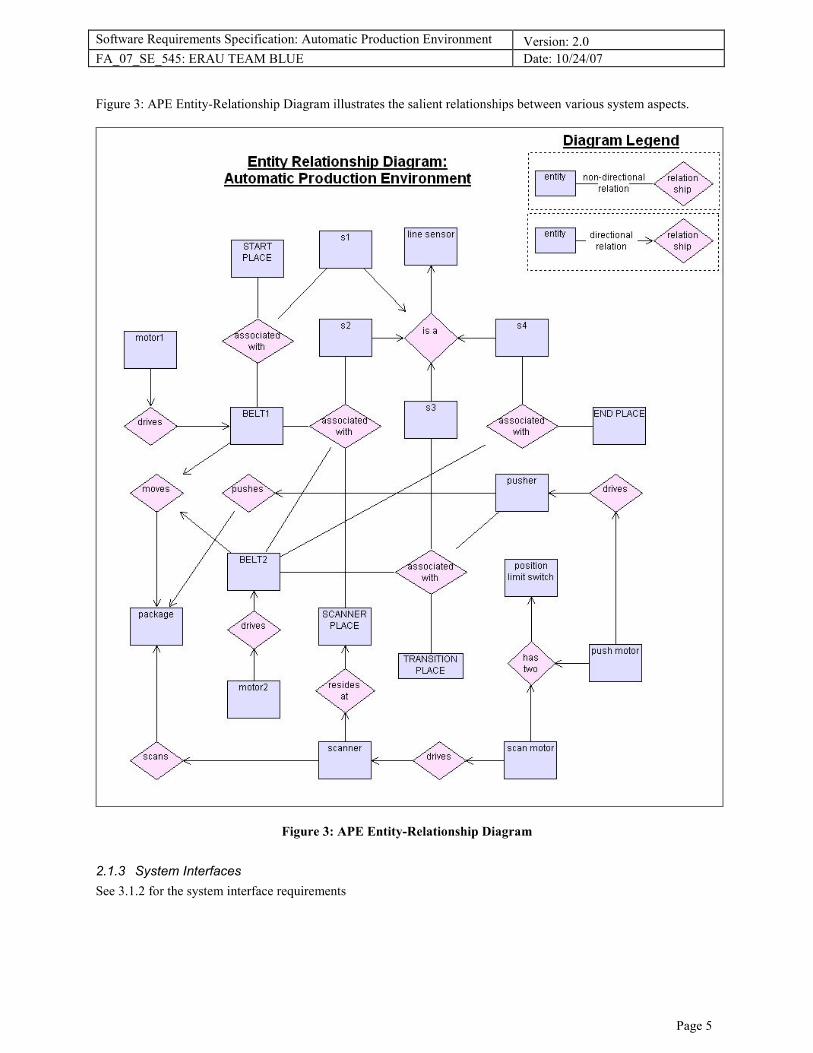
Figure 3: APE Entity-Relationship Diagram illustrates the salient relationships between various system aspects.
Figure 3: APE Entity-Relationship Diagram
2.1.3 System Interfaces
See 3.1.2 for the system interface requirements
Software Requirements Specification: Automatic Production Environment Version: 2.0
FA_07_SE_545: ERAU TEAM BLUE Date: 10/24/07
Page 6
2.1.4 User Interfaces
See 3.3.1 for the user interface requirements
2.1.5 Hardware Interfaces
See 3.2 for the hardware interface requirements.
2.1.6 Software Interfaces
Section not used.
2.1.7 Communications Interfaces
Section not used.
2.2 Product Functions
Section not used.
2.3 User Characteristics
2.3.1 Local Operator
The local operator physically interacts with the hardware of the system, adding and removing packages to be
processed to and from the system.
[SYS_USER1] The local operator shall be able to place a package at any one of four places and only at any one
of these four places.
[SYS_USER1.1] The local operator shall be able to place a package at the START PLACE.
[SYS_USER1.2] The local operator shall be able to place a package at the SCAN PLACE.
[SYS_USER1.3] The local operator shall be able to place a package at the TRANSITION PLACE.
[SYS_USER1.4] The local operator shall be able to place a package at the END PLACE.
[SYS_USER2] The local operator shall only place a package when the system is in an idle state.
2.3.2 Web Operator
The web operator remotely interacts with the system, and has the ability to monitor the system and remotely control
its motors.
[SYS_USER3] The web operator shall be able to observe the status of the system sensors and actuators through
the web interface.
[SYS_USER4] The web operator shall be able to manually take control of the system by activating any of the
individual actuators through the web interface.
[SYS_USER5] The web operator shall be able to return automatic control to the system.
2.4 Constraints
2.4.1 Development Constraints
[SYS_CNST1] The system shall be implemented on Arcom GX-1 target.
[SYS_CNST2] The developers shall keep a log to record the time spent in the project-related activities.
[SYS_CNST3] The developers shall follow guidance from a set of process scripts developed for the project.
[SYS_CNST4] The system should be developed with the concepts of modularity, strong cohesion within a
module, and light coupling between modules.
[SYS_CNST5] Deleted.
Software Requirements Specification: Automatic Production Environment Version: 2.0
FA_07_SE_545: ERAU TEAM BLUE Date: 10/24/07
Page 7
[SYS_CNST6] The system shall check for runtime errors, result reasonableness, and mathematical error.
[SYS_CNST7] The system shall use multiple tasks/processes to handle the data acquisition, processing, storage,
timing, and communications (where applicable real-time programming principles will be used).
[SYS_CNST8] Deleted.
[SYS_CNST9] Possible use of alternate hardware interfaces with the Arcom box shall be considered (USB,
keypad, display, etc.).
[SYS_CNST10] The system software shall be developed with, at the minimum, the following formal software
artifacts compiled as appendices to the Project Report (a document easy to view on internet compiled at the end
of the lifecycle containing overall information on the project scope, team organization, observations,
effort/defect data, etc.):
• Development Plan
• Requirements Document
• Test Plan
• Design Document
• Configuration Management Document
• Source Code
• Test Results
• User's Manual
[SYS_CNST11] The development shall use facilities of RTLab (LB131) and Guidant Lab (LB160).
[SYS_CNST12] The primary tools used for development shall be Tornado/VxWorks (Arcom).
2.4.2 Standards Compliance
[SYS_STRD1] Manually produced code shall conform to an established C coding standard (e.g. MISRA).
[SYS_STRD2] Requirements/design shall use accepted notations (e.g. UML, structured, data/control-flow).
[SYS_STRD3] Team time record data shall be collected and included in the final report.
2.5 Assumptions and Dependencies
[ASMP1] Package shall not be placed or “appear out of nowhere” while the system is not in an idle state.
[ASMP2] Package placement into the system shall only occur in a way that triggers one of the line sensors (s1-
s4) to detect the package’s presence.
[ASMP3] The scanner in the “down” position is sufficient for scanning a package; the scanner does not need to
actually make contact with the package.
[ASMP4] Timeout behavior for belt activity and limits on scan and push attempts shall not be imposed in the
requirements; those are reserved as design decisions or are as of yet TBD.
[ASMP5] A package shall only be placed into the system when the system is off or in an idle state.
[ASMP6] The push cycle (pusher in home position extends to extended position and returns home) is perceived
by the system as an atomic operation.
[ASMP7] The scan cycle (scanner in home position extends to scanning position and returns home) is perceived
by the system as an atomic operation.
[ASMP8] The system behaves in a way such that only one belt shall be in operation at any time.
[ASMP9] Packages cannot be removed from the system except for those that have been detected by the system
at the END PLACE; i.e. packages will not “disappear.”
3. Specific Requirements
3.1 System Requirements
3.1.1 System Functional Requirements
Refer to Figure 1: Automatic Production Environment - Logical Component Layout for the following requirements:
[SYS_FUNC1] When an item at the START PLACE is detected and the SCAN PLACE is empty, the BELT1
shall start moving until package reaches SCAN PLACE.
Software Requirements Specification: Automatic Production Environment Version: 2.0
FA_07_SE_545: ERAU TEAM BLUE Date: 10/24/07
Page 8
[SYS_FUNC2] When the item reaches SCAN PLACE the BELT1 shall stop.
[SYS_FUNC3] After 2 seconds and when the item is in the SCAN PLACE, the scanner shall engage (going
down).
[SYS_FUNC4] After 10 seconds of scanning, scanner shall disengage (going up).
[SYS_FUNC5] Five seconds after scanning stops, and if the TRANSITION PLACE is empty, the PUSHER shall
engage to move the item into the BELT2.
[SYS_FUNC6] When the item is detected at the TRANSITION PLACE and there is no item at the END
PLACE, the BELT2 shall start moving.
[SYS_FUNC7] When the item reaches END PLACE, the BELT2 shall stop.
[SYS_FUNC8] Deleted.
[SYS_FUNC8.1] The software shall track the processed item with a serial number.
[SYS_FUNC8.2] The software shall track the processed item with a respective time stamp.
[SYS_FUNC8.3] The software shall archive the processed items in such a way that maintains their serial number
and a respective time stamp.
[SYS_FUNC9] The software shall display deviations from a normal operation.
[SYS_FUNC11] The system shall give “package clearing” precedence to items closer to the END PLACE of the
production line before processing items closer to the START PLACE; e.g. if the system detects package B ahead
of a package A, it will process package B first.
3.1.2 System Interface Requirements
[INT_SYS1] The software shall consist of a User Interface (UI) to provide user control over the system
operation via keyboard/mouse/joystick/display.
[INT_SYS2] The system shall consist of a Target Computer (TC) that will exert the software control over the
hardware system.
3.1.3 Timing Constraints
[SYS_CNST11] Data acquired by the Target Computer shall conform to specified timing acquisition rate (timing
acquisition rate to TBD in design phase).
[SYS_CNST12] Data generated by the Target Computer shall conform to specified response time (response time
TBD in design phase).
3.2 Hardware Requirements
3.2.1 Hardware Constraints
[HW_CNST1] The system shall be constructed with (but not exclusively with) a composition of FischerTechnik
system parts.
[HW_CNST2] Deleted.
[HW_CNST3] The conveyor belt simulator shall be constructed to appear as an L-shaped form, with BELT1
connected orthogonally to the scanning area, and the scanning area being collinearly connected to BELT2.
[HW_CNST4] The hardware configuration shall allow for placing four additional sensors to provide redundancy
(maximum 4 motors and 8 sensors).
3.2.2 Hardware Nonfunctional Requirements
[HW_NONF1] The system shall be composed of a computer terminal, an Arcom GX-1 target and a conveyor
belt simulator.
[HW_NONF2] The conveyor belt simulator shall be constructed to model an airport conveyor belt with a
scanning machine.
[HW_NONF3] The conveyor belt simulator shall be composed of a Fischertechnik ROBO controller with 1
standard serial port and connections for all motors and sensors.
[HW_NONF4] The conveyor belt simulator shall be composed of two conveyor belts to carry objects through
the scanner.
Software Requirements Specification: Automatic Production Environment Version: 2.0
FA_07_SE_545: ERAU TEAM BLUE Date: 10/24/07
Page 9
[HW_NONF5] The conveyor belt simulator shall contain 4 electric motors: motor1, motor2, scan motor and
push motor.
[HW_NONF6] The conveyor belt simulator shall contain 4 sets of sensors: sensor1, sensor2, sensor3 and
sensor4.
[HW_NONF7] The conveyor belt simulator shall contain 1 scanner device (called "scanner") that will be placed
over the scanning area.
[HW_NONF8] The conveyor belt simulator shall contain 1 ejector device (called "pusher") placed within the
scanning area.
[HW_NONF9] The scanner device shall have two position sensing limit switches.
[HW_NONF10] The ejector device shall have two position sensing limit switches.
3.2.3 Hardware Functional Requirements
[HW_FUNC1] Motor1 shall be responsible for driving BELT1.
[HW_FUNC2] Motor3 shall be responsible for positioning the scanner upwards and downwards.
[HW_FUNC3] Motor4 shall be responsible for positioning the pusher in order take the object from the scanning
position to BELT2.
[HW_FUNC4] Motor2 shall be responsible for driving BELT2.
[HW_FUNC5] Sensor1 shall be used to sense an object at the beginning of BELT1and shall correspond to the
START PLACE.
[HW_FUNC6] Sensor2 shall be used in the scanner area to detect the presence of the object in the scanner area
and shall correspond to the SCAN PLACE.
[HW_FUNC7] The scanner shall be responsible for scanning the object.
[HW_FUNC8] The pusher shall be responsible for clearing the object out of the scanning area.
[HW_FUNC9] Sensor3 shall be used to detect an object at the beginning of BELT2 and shall correspond to the
TRANSITION PLACE.
[HW_FUNC10] Sensor4 shall be used to detect an object at the end of BELT2 and shall correspond to the END
PLACE.
3.3 External Interface Requirements
3.3.1 User Interfaces
3.3.1.1 User Interface: web page
[INT_USER1] The user interface shall be created as single web page.
[INT_USER1.1] The user interface should (but not shall) be implemented as an HTML based page.
3.3.1.2 User Interface: status view
[INT_USER2] The user shall be able to view the status of the system from the page described in [INT_USER1].
[INT_USER2.1] The areas or page showing the system status shall refresh no less frequently than once per every
2 seconds.
[INT_USER2.1.1] The interface shall provide a means to force a refresh earlier than would occur automatically.
[INT_USER2.2] The status values shall be assigned from an enumerated set
[INT_USER2.2.1] The sensors (sensor1 and sensor2) shall be assigned one of two statuses: "detect" or "no
detect.”
[INT_USER2.2.2] Deleted.
[INT_USER2.2.3] The pusher shall be assigned one of two statuses: "extended" or "home".
[INT_USER2.2.4] The scanner shall be assigned one of two statuses: "scanning" or "home".
[INT_USER2.2.5] motor1 shall correspond to BELT1 and shall be assigned one of two statuses: "active" or
"inactive.”
[INT_USER2.2.6] motor2 shall correspond to BELT2 and shall be assigned one of two statuses: "active" or
"inactive.”
[INT_USER2.3] The interface shall have an indicator to display sensor1's status.
Software Requirements Specification: Automatic Production Environment Version: 2.0
FA_07_SE_545: ERAU TEAM BLUE Date: 10/24/07
Page 10
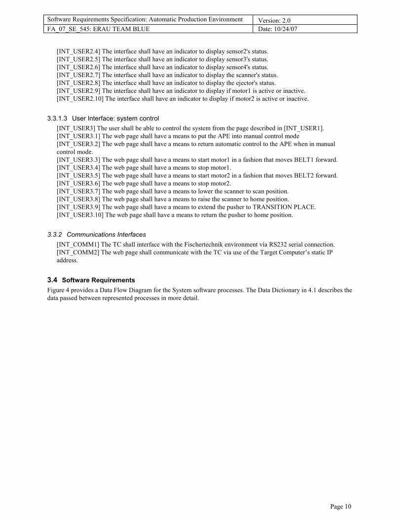
[INT_USER2.4] The interface shall have an indicator to display sensor2's status.
[INT_USER2.5] The interface shall have an indicator to display sensor3's status.
[INT_USER2.6] The interface shall have an indicator to display sensor4's status.
[INT_USER2.7] The interface shall have an indicator to display the scanner's status.
[INT_USER2.8] The interface shall have an indicator to display the ejector's status.
[INT_USER2.9] The interface shall have an indicator to display if motor1 is active or inactive.
[INT_USER2.10] The interface shall have an indicator to display if motor2 is active or inactive.
3.3.1.3 User Interface: system control
[INT_USER3] The user shall be able to control the system from the page described in [INT_USER1].
[INT_USER3.1] The web page shall have a means to put the APE into manual control mode
[INT_USER3.2] The web page shall have a means to return automatic control to the APE when in manual
control mode.
[INT_USER3.3] The web page shall have a means to start motor1 in a fashion that moves BELT1 forward.
[INT_USER3.4] The web page shall have a means to stop motor1.
[INT_USER3.5] The web page shall have a means to start motor2 in a fashion that moves BELT2 forward.
[INT_USER3.6] The web page shall have a means to stop motor2.
[INT_USER3.7] The web page shall have a means to lower the scanner to scan position.
[INT_USER3.8] The web page shall have a means to raise the scanner to home position.
[INT_USER3.9] The web page shall have a means to extend the pusher to TRANSITION PLACE.
[INT_USER3.10] The web page shall have a means to return the pusher to home position.
3.3.2 Communications Interfaces
[INT_COMM1] The TC shall interface with the Fischertechnik environment via RS232 serial connection.
[INT_COMM2] The web page shall communicate with the TC via use of the Target Computer’s static IP
address.
3.4 Software Requirements
Figure 4 provides a Data Flow Diagram for the System software processes. The Data Dictionary in 4.1 describes the
data passed between represented processes in more detail.

Software Requirements Specification: Automatic Production Environment Version: 2.0
FA_07_SE_545: ERAU TEAM BLUE Date: 10/24/07
Page 11
Figure 4: Data Flow Diagram for All Software Modes
Software Requirements Specification: Automatic Production Environment Version: 2.0
FA_07_SE_545: ERAU TEAM BLUE Date: 10/24/07
Page 12
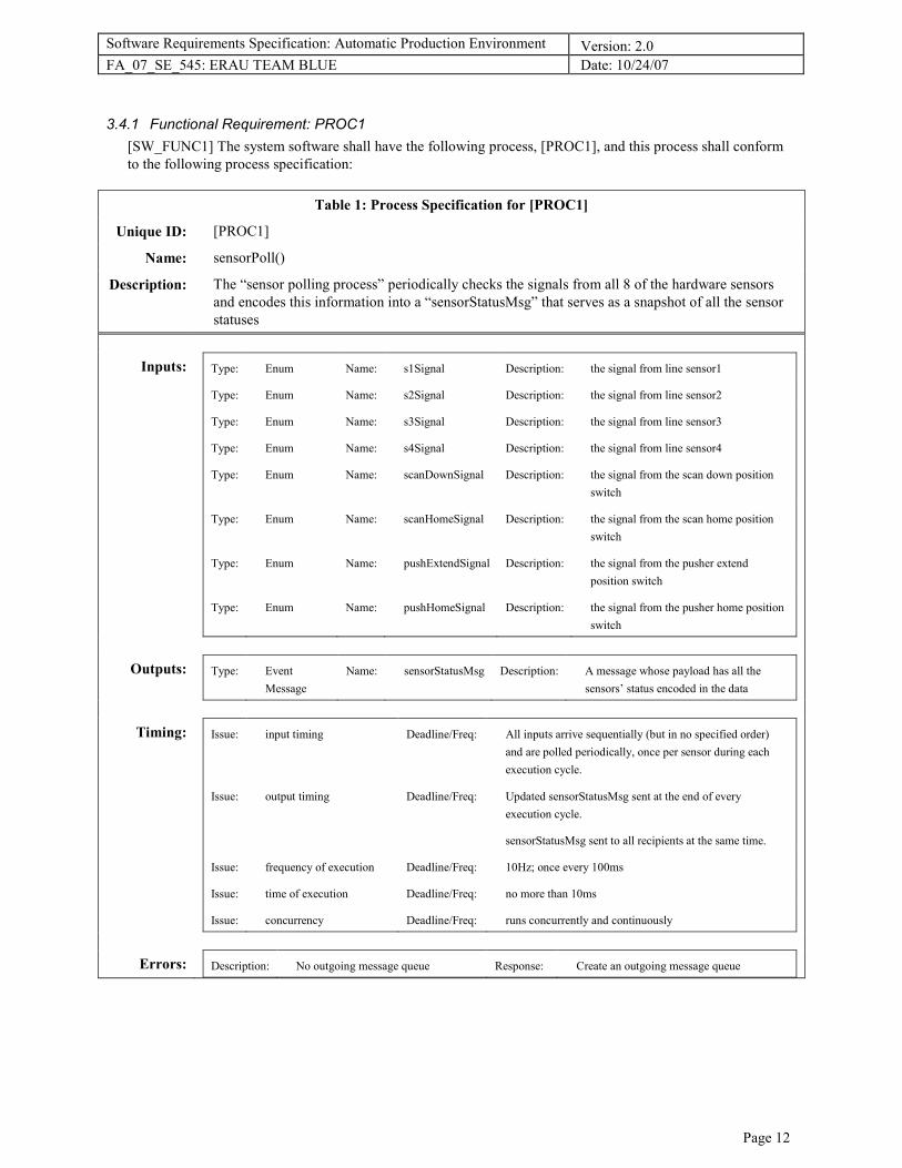
3.4.1 Functional Requirement: PROC1
[SW_FUNC1] The system software shall have the following process, [PROC1], and this process shall conform
to the following process specification:
Table 1: Process Specification for [PROC1]
Unique ID: [PROC1]
Name: sensorPoll()
Description: The “sensor polling process” periodically checks the signals from all 8 of the hardware sensors
and encodes this information into a “sensorStatusMsg” that serves as a snapshot of all the sensor
statuses
Inputs: Type: Enum Name: s1Signal Description: the signal from line sensor1
Type: Enum Name: s2Signal Description: the signal from line sensor2
Type: Enum Name: s3Signal Description: the signal from line sensor3
Type: Enum Name: s4Signal Description: the signal from line sensor4
Type: Enum Name: scanDownSignal Description: the signal from the scan down position
switch
Type: Enum Name: scanHomeSignal Description: the signal from the scan home position
switch
Type: Enum Name: pushExtendSignal Description: the signal from the pusher extend
position switch
Type: Enum Name: pushHomeSignal Description: the signal from the pusher home position
switch
Outputs: Type: Event
Message
Name: sensorStatusMsg Description: A message whose payload has all the
sensors’ status encoded in the data
Timing: Issue: input timing Deadline/Freq: All inputs arrive sequentially (but in no specified order)
and are polled periodically, once per sensor during each
execution cycle.
Issue: output timing Deadline/Freq: Updated sensorStatusMsg sent at the end of every
execution cycle.
sensorStatusMsg sent to all recipients at the same time.
Issue: frequency of execution Deadline/Freq: 10Hz; once every 100ms
Issue: time of execution Deadline/Freq: no more than 10ms
Issue: concurrency Deadline/Freq: runs concurrently and continuously
Errors: Description: No outgoing message queue Response: Create an outgoing message queue

Software Requirements Specification: Automatic Production Environment Version: 2.0
FA_07_SE_545: ERAU TEAM BLUE Date: 10/24/07
Page 13
3.4.2 Functional Requirement: PROC2
[SW_FUNC2] The system software shall have the following process, [PROC2], and this process shall conform
to the following process specification:
Table 2: Process Specification for [PROC2]
Unique ID: [PROC2]
Name: autoControl()
Description: The “auto control process” has a predetermined table of responses for each possible sensor signal
combinations. Accepts a sensorStatusMsg, looks up the correct reaction and sends out an
autoControlMsg only if the current state of control needs to be changed. May be disabled with a
toggle input. Can only send outputs if system in automatic control mode.
Inputs: Type: Event
Message
Name: sensorStatusMsg Description: A message whose payload has all the
sensors’ status encoded in the data
Type: Event
Message
Name: toggle Description: request for releasing control to
userControl() or returning control from
userControl()
Outputs: Type: Event
Message
Name: autoControlMsg Description: Contains an actuator control command
Timing: Issue: input timing Deadline/Freq: sensorStatusMsg arrives continuously and periodically.
toggle arrives sporadically and at different times than
sensorStatusMsg.
Issue: output timing Deadline/Freq: autoControlMsg sent sporadically.
autoControlMsg sent to all recipients at the same time.
Can only send autoControlMsg when in automatic control
mode.
Issue: frequency of execution Deadline/Freq: 10Hz; once every 100ms
Issue: time of execution Deadline/Freq: no more than 10ms
Issue: concurrency Deadline/Freq: runs concurrently and continuously
Errors: Description: No incoming message queue Response: none
Description: No outgoing message queue Response: Create an outgoing message queue

Software Requirements Specification: Automatic Production Environment Version: 2.0
FA_07_SE_545: ERAU TEAM BLUE Date: 10/24/07
Page 14
[SW_FUNC2.1] PROC2 shall behave in a manner that is consistent with the Response Lookup Table for
autoControl() (Table 3: Response Lookup Table for [PROC2] autoControl()).
Table 3: Response Lookup Table for [PROC2] autoControl()
s4 s3 s2 s1 motor1 motor2 scanner pusher
no detect no detect no detect no detect inactive inactive inactive inactive
no detect no detect no detect detect active inactive inactive inactive
no detect no detect detect no detect inactive inactive UC2 UC3
no detect no detect detect detect inactive inactive UC2 UC3
no detect detect no detect no detect inactive active inactive inactive
no detect detect no detect detect inactive active inactive inactive
no detect detect detect no detect inactive active inactive inactive
no detect detect detect detect inactive active inactive inactive
detect no detect no detect no detect inactive inactive inactive inactive
detect no detect no detect detect inactive inactive inactive inactive
detect no detect detect no detect inactive inactive inactive inactive
detect no detect detect detect inactive inactive inactive inactive
detect detect no detect no detect inactive inactive inactive inactive
detect detect no detect detect inactive inactive inactive inactive
detect detect detect no detect inactive inactive inactive inactive
detect detect detect detect inactive inactive inactive inactive
Software Requirements Specification: Automatic Production Environment Version: 2.0
FA_07_SE_545: ERAU TEAM BLUE Date: 10/24/07
Page 15
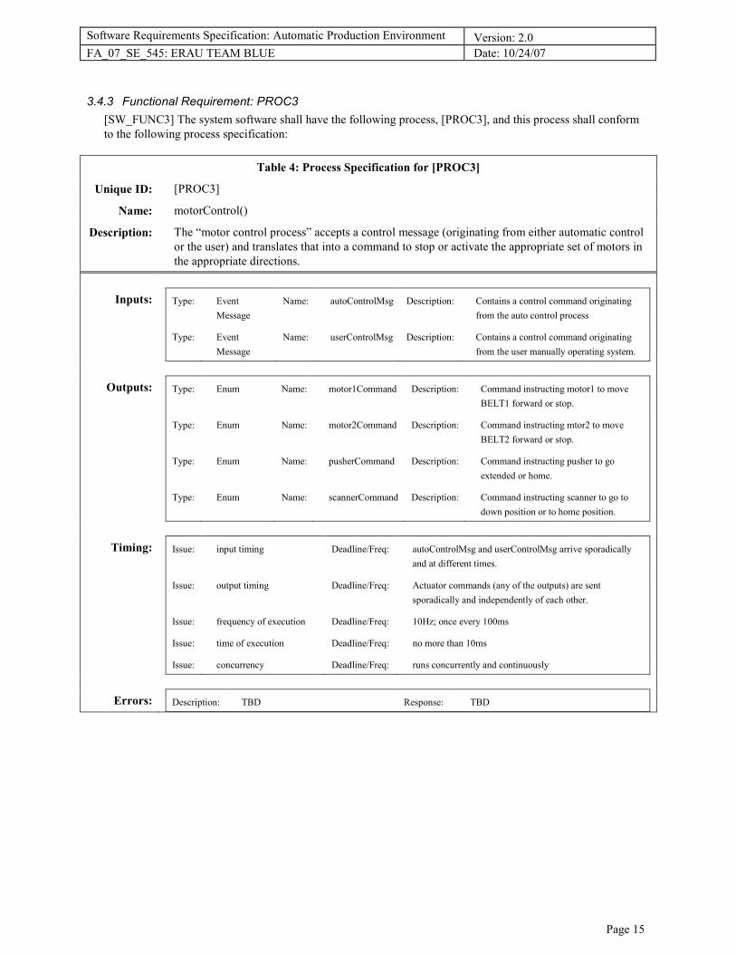
3.4.3 Functional Requirement: PROC3
[SW_FUNC3] The system software shall have the following process, [PROC3], and this process shall conform
to the following process specification:
Table 4: Process Specification for [PROC3]
Unique ID: [PROC3]
Name: motorControl()
Description: The “motor control process” accepts a control message (originating from either automatic control
or the user) and translates that into a command to stop or activate the appropriate set of motors in
the appropriate directions.
Inputs: Type: Event
Message
Name: autoControlMsg Description: Contains a control command originating
from the auto control process
Type: Event
Message
Name: userControlMsg Description: Contains a control command originating
from the user manually operating system.
Outputs: Type: Enum Name: motor1Command Description: Command instructing motor1 to move
BELT1 forward or stop.
Type: Enum Name: motor2Command Description: Command instructing mtor2 to move
BELT2 forward or stop.
Type: Enum Name: pusherCommand Description: Command instructing pusher to go
extended or home.
Type: Enum Name: scannerCommand Description: Command instructing scanner to go to
down position or to home position.
Timing: Issue: input timing Deadline/Freq: autoControlMsg and userControlMsg arrive sporadically
and at different times.
Issue: output timing Deadline/Freq: Actuator commands (any of the outputs) are sent
sporadically and independently of each other.
Issue: frequency of execution Deadline/Freq: 10Hz; once every 100ms
Issue: time of execution Deadline/Freq: no more than 10ms
Issue: concurrency Deadline/Freq: runs concurrently and continuously
Errors: Description: TBD Response: TBD
Software Requirements Specification: Automatic Production Environment Version: 2.0
FA_07_SE_545: ERAU TEAM BLUE Date: 10/24/07
Page 16
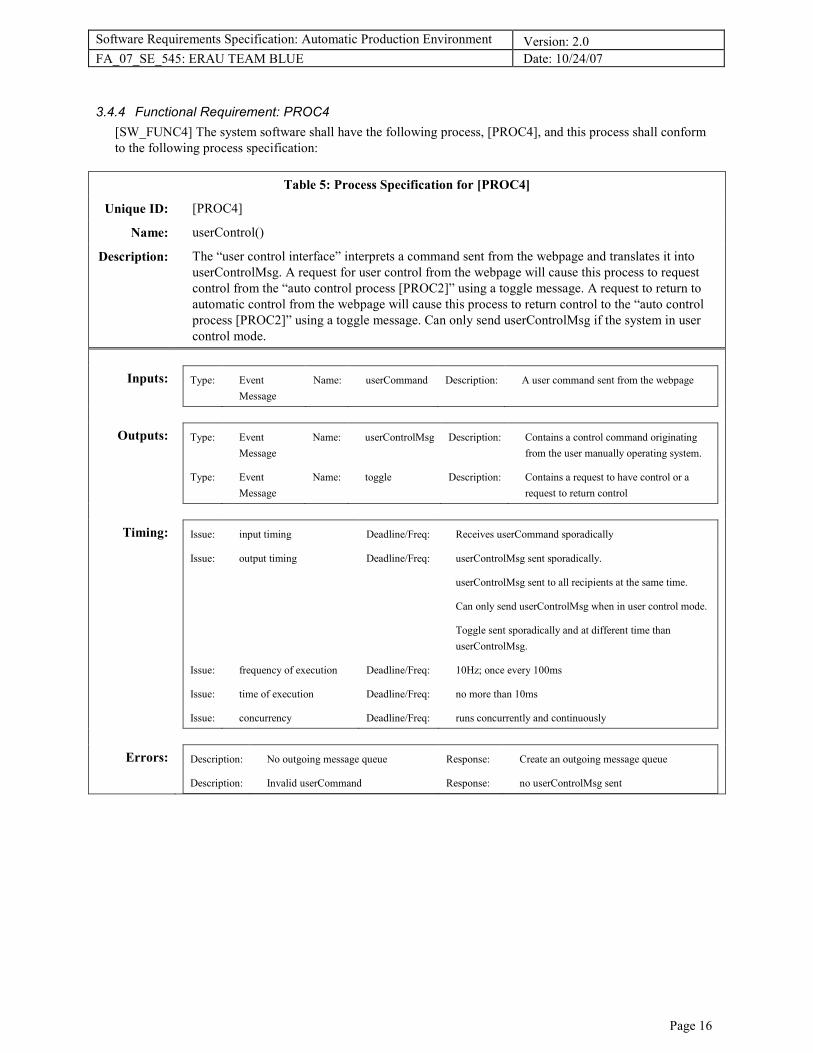
3.4.4 Functional Requirement: PROC4
[SW_FUNC4] The system software shall have the following process, [PROC4], and this process shall conform
to the following process specification:
Table 5: Process Specification for [PROC4]
Unique ID: [PROC4]
Name: userControl()
Description: The “user control interface” interprets a command sent from the webpage and translates it into
userControlMsg. A request for user control from the webpage will cause this process to request
control from the “auto control process [PROC2]” using a toggle message. A request to return to
automatic control from the webpage will cause this process to return control to the “auto control
process [PROC2]” using a toggle message. Can only send userControlMsg if the system in user
control mode.
Inputs: Type: Event
Message
Name: userCommand Description: A user command sent from the webpage
Outputs: Type: Event
Message
Name: userControlMsg Description: Contains a control command originating
from the user manually operating system.
Type: Event
Message
Name: toggle Description: Contains a request to have control or a
request to return control
Timing: Issue: input timing Deadline/Freq: Receives userCommand sporadically
Issue: output timing Deadline/Freq: userControlMsg sent sporadically.
userControlMsg sent to all recipients at the same time.
Can only send userControlMsg when in user control mode.
Toggle sent sporadically and at different time than
userControlMsg.
Issue: frequency of execution Deadline/Freq: 10Hz; once every 100ms
Issue: time of execution Deadline/Freq: no more than 10ms
Issue: concurrency Deadline/Freq: runs concurrently and continuously
Errors: Description: No outgoing message queue Response: Create an outgoing message queue
Description: Invalid userCommand Response: no userControlMsg sent

Software Requirements Specification: Automatic Production Environment Version: 2.0
FA_07_SE_545: ERAU TEAM BLUE Date: 10/24/07
Page 17
3.4.5 Functional Requirement: PROC5
[SW_FUNC5] The system software shall have the following process, [PROC5], and this process shall conform
to the following process specification:
Table 6: Process Specification for [PROC5]
Unique ID: [PROC5]
Name: statusManager()
Description: The “status manager process” receives, stores, and maintains status information from the sensors
and current motor commands. It keeps track and archives the processed messages with their serial
number and a respective time stamps. It sends a sysStatusMsg to the webpage providing the user
feedback on the internal state of the system.
Inputs: Type: Event
Message
Name: sensorStatusMsg Description: A message whose payload has all the
sensors’ status encoded in the data
Type: Event
Message
Name: autoControlMsg Description: Contains a control command originating
from the auto control process
Type: Event
Message
Name: userControlMsg Description: Contains a control command originating
from the user manually operating system
Outputs: Type: Event
Message
Name: sysStatusMsg Description: A message whose payload contains
information on the current state of all
sensors and actuator (motor) activity
Timing: Issue: input timing Deadline/Freq: sensorStatusMsg arrives continuously and periodically.
autoControlMsg and userControlMsg arrive sporadically
and at different times.
Issue: output timing Deadline/Freq: updated sysStatusMsg sent at the end of every execution
cycle
Issue: frequency of execution Deadline/Freq: 10Hz; once every 100ms
Issue: time of execution Deadline/Freq: no more than 10ms
Issue: concurrency Deadline/Freq: runs concurrently and continuously
Errors: Description: No incoming message queue Response: none
Description: Unspecified error Response: Report error to webpage

Software Requirements Specification: Automatic Production Environment Version: 2.0
FA_07_SE_545: ERAU TEAM BLUE Date: 10/24/07
Page 18
3.4.6 System Modes
Figure 5 provides a state chart diagram depicting the possible states in which the system can be.
Figure 5: APE State Chart
[SW_FUNC6] The software shall operate in two modes: user control and auto control
[SW_FUNC6.1] The auto control mode shall have 5 states of operation: “idle,” “BELT1 forward,” “scanning,”
“pushing,” and “BELT2 forward.”
[SW_FUNC6.1.1] No motor activity shall occur while in the idle state in auto mode.
[SW_FUNC6.2] The user control mode shall have 5 states of operation: “idle,” “BELT1 forward,” “scanning,”
“pushing,” and “BELT2 forward.”
[SW_FUNC6.2.1] No motor activity shall occur while in the idle state in auto mode.
[SW_FUNC6.3] The auto control mode shall be the default mode of operation.
[SW_FUNC6.4] Only one belt (BELT1 or BELT2) shall be active at any time (see [ASMP8]).
Software Requirements Specification: Automatic Production Environment Version: 2.0
FA_07_SE_545: ERAU TEAM BLUE Date: 10/24/07
Page 19
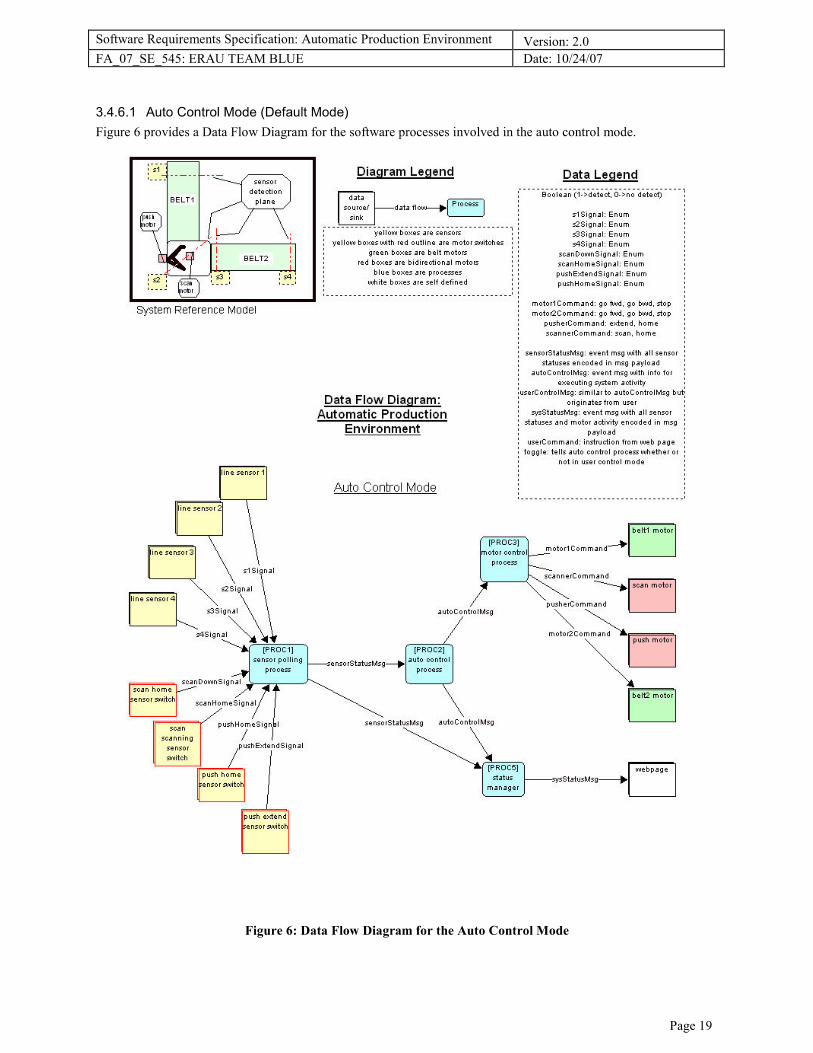
3.4.6.1 Auto Control Mode (Default Mode)
Figure 6 provides a Data Flow Diagram for the software processes involved in the auto control mode.
Figure 6: Data Flow Diagram for the Auto Control Mode
Software Requirements Specification: Automatic Production Environment Version: 2.0
FA_07_SE_545: ERAU TEAM BLUE Date: 10/24/07
Page 20
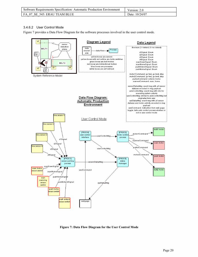
3.4.6.2 User Control Mode
Figure 7 provides a Data Flow Diagram for the software processes involved in the user control mode.
Figure 7: Data Flow Diagram for the User Control Mode

Software Requirements Specification: Automatic Production Environment Version: 2.0
FA_07_SE_545: ERAU TEAM BLUE Date: 10/24/07
Page 21
3.5 Performance Requirements
The timing diagram in Figure 8 illustrates the system timing requirements.
[SW_PERF1] Deleted. Utilization requirements deferred to design..
[SW_PERF2] Deleted. Timing requirements deferred to design.
Figure 8: APE Timing Diagram for 100ms Hyper-period
3.6 Design Constraints
No design constraints at this time.
3.7 Software System Attributes
No specified software system attributes at this time.
3.8 Other Requirements
No other requirements at this time.
4. Appendices
4.1 Data Dictionary
Automatic Production Environment: Data Dictionary autoControlMsg = Contains an actuator control command originating from system's automatic
control process,
Type: Event Message
motor1Command = Command instructing motor1 to move or stop BELT1,
Type: Enumerated value
[forward | backward | stop]
motor2Command = Command instructing motor2 to move or stop BELT2,
Type: Enumerated value
[forward | backward | stop]
pusherCommand = Command instructing pusher to go extended or home,
Type: Enumerated value
[home | extend | stop]
pushExtendSignal = the signal from the pusher extend position switch,
Type: Enumerated value
[true | false | error]
Software Requirements Specification: Automatic Production Environment Version: 2.0
FA_07_SE_545: ERAU TEAM BLUE Date: 10/24/07
Page 22
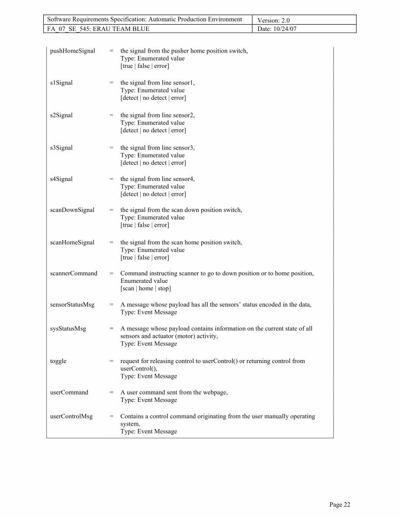
pushHomeSignal = the signal from the pusher home position switch,
Type: Enumerated value
[true | false | error]
s1Signal = the signal from line sensor1,
Type: Enumerated value
[detect | no detect | error]
s2Signal = the signal from line sensor2,
Type: Enumerated value
[detect | no detect | error]
s3Signal = the signal from line sensor3,
Type: Enumerated value
[detect | no detect | error]
s4Signal = the signal from line sensor4,
Type: Enumerated value
[detect | no detect | error]
scanDownSignal = the signal from the scan down position switch,
Type: Enumerated value
[true | false | error]
scanHomeSignal = the signal from the scan home position switch,
Type: Enumerated value
[true | false | error]
scannerCommand = Command instructing scanner to go to down position or to home position,
Enumerated value
[scan | home | stop]
sensorStatusMsg = A message whose payload has all the sensors’ status encoded in the data,
Type: Event Message
sysStatusMsg = A message whose payload contains information on the current state of all
sensors and actuator (motor) activity,
Type: Event Message
toggle = request for releasing control to userControl() or returning control from
userControl(),
Type: Event Message
userCommand = A user command sent from the webpage,
Type: Event Message
userControlMsg = Contains a control command originating from the user manually operating
system,
Type: Event Message

Software Requirements Specification: Automatic Production Environment Version: 2.0
FA_07_SE_545: ERAU TEAM BLUE Date: 10/24/07
Page 23
4.2 Use Cases
4.2.1 Use Case Diagram
Figure 9: APE Use Case Diagram

Software Requirements Specification: Automatic Production Environment Version: 2.0
FA_07_SE_545: ERAU TEAM BLUE Date: 10/24/07
Page 24
4.2.2 Use Case Scenarios
4.2.2.1 UC1: BELT1 Moves Package
Table 7: UC1: BELT1 Moves Package
UC1: BELT1 Moves Package
Super Use Case
Author Pfeifer, Griffis
Date
Oct 1, 2007 6:28:46 PM
Updated 10/5/07 12:02 PM
Updated 10/10/07 12:48 AM
Brief Description A package is sensed at sensor1 (START PLACE) and the system responds by moving the package via conveyor BELT1 until detected at sensor2 (SCAN PLACE).
Preconditions
No other packages sensed on the conveyor belt ( sensors 2, 3, and 4 no detect and scanner in home position and
pusher in home position)
No packages being moved about the conveyor belt
Post-conditions Package has activated sensor2 (SCAN PLACE).
Actor Input System Response
1 Package detected at sensor1 (START PLACE)
2 Ensure sensor2, sensor3, and sensor4 no detect
3 Start conveyor BELT1 to move package
4 When sensor2 detects: stop conveyor BELT1.
5 (Continue to UC2)
Flow of Events
Error/Deviation System Response
[UC1.E1] BELT1 Does not turn on. System error addressed but system response not imposed in requirements. Deferred as a design decision.
[UC1.E2] BELT1 turned on but package does not leave START PLACE System error addressed but system response not imposed in requirements.
Deferred as a design decision.
[UC1.E3] Package left START PLACE and belt is on but package does not reach/trigger sensor2 (SCAN PLACE)
System error addressed but system response not imposed in requirements. Deferred as a design decision.
Software Requirements Specification: Automatic Production Environment Version: 2.0
FA_07_SE_545: ERAU TEAM BLUE Date: 10/24/07
Page 25
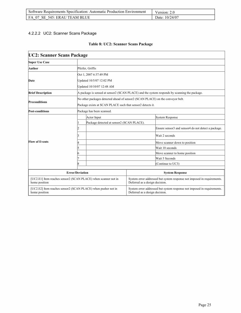
4.2.2.2 UC2: Scanner Scans Package
Table 8: UC2: Scanner Scans Package
UC2: Scanner Scans Package
Super Use Case
Author Pfeifer, Griffis
Date
Oct 1, 2007 6:37:49 PM
Updated 10/5/07 12:02 PM
Updated 10/10/07 12:48 AM
Brief Description A package is sensed at sensor2 (SCAN PLACE) and the system responds by scanning the package.
Preconditions No other packages detected ahead of sensor2 (SCAN PLACE) on the conveyor belt.
Package exists at SCAN PLACE such that sensor2 detects it.
Post-conditions Package has been scanned.
Actor Input System Response
1 Package detected at sensor2 (SCAN PLACE).
2 Ensure sensor3 and sensor4 do not detect a package.
3 Wait 2 seconds
4 Move scanner down to position
5 Wait 10 seconds
6 Move scanner to home position
7 Wait 5 Seconds
8 (Continue to UC3)
Flow of Events
Error/Deviation System Response
[UC2.E1] Item reaches sensor2 (SCAN PLACE) when scanner not in home position
System error addressed but system response not imposed in requirements. Deferred as a design decision.
[UC2.E2] Item reaches sensor2 (SCAN PLACE) when pusher not in
home position
System error addressed but system response not imposed in requirements.
Deferred as a design decision.

Software Requirements Specification: Automatic Production Environment Version: 2.0
FA_07_SE_545: ERAU TEAM BLUE Date: 10/24/07
Page 26
4.2.2.3 UC3: Pusher Pushes Package
Table 9: UC3: Pusher Pushes Package
UC3: Pusher Pushes Package
Super Use Case
Author Pfeifer, Griffis
Date
Oct 1, 2007 6:38:00 PM
Updated 10/5/07 12:02 PM
Updated 10/10/07 12:48 AM
Brief Description A package exists in the SCAN PLACE and has been scanned. The system responds by moving the package via the pusher to sensor3 (TRANSITION PLACE).
Preconditions
Package exists at SCAN PLACE and is detected by sensor2.
No other packages detected ahead of sensor3 (TRANSITION PLACE) on conveyor belt.
Package has been scanned.
Scanner in the home position.
Post-conditions Package has activated sensor3.
Actor Input System Response
1 Package detected at sensor2 (SCAN PLACE).
2 Move pusher to extend position
3
When pusher extend detected, return pusher to home position
4 When pusher detected home, check sensor3
5 If sensor3 does not detect, go to step 1.
6 (Continue to UC4)
Flow of Events
Error/Deviation System Response
[UC3.E1] Package being pushed by pusher does not reach/trigger sensor3 (TRANSITION PLACE)
System error addressed but system response not imposed in requirements. Deferred as a design decision.
[UC3.E2] Pusher cycles but package does not leave SCAN PLACE System error addressed but system response not imposed in requirements.
Deferred as a design decision.
[UC3.E3] Package leaves SCAN PLACE and pusher is on but does not reach/trigger sensor3 (TRANSITION PLACE)
System error addressed but system response not imposed in requirements. Deferred as a design decision.
[UC3.E4] BELT2 turned on but package does not leave TRANSITION
PLACE
System error addressed but system response not imposed in requirements.
Deferred as a design decision.

Software Requirements Specification: Automatic Production Environment Version: 2.0
FA_07_SE_545: ERAU TEAM BLUE Date: 10/24/07
Page 27
4.2.2.4 UC4: BELT2 Moves Package
Table 10: UC4: BELT2 Moves Package
UC4: BELT2 Moves Package
Super Use Case
Author Pfeifer, Griffis
Date Oct 5, 2007 12:02 PM
Updated 10/10/07 12:48 AM
Brief Description A package is detected at sensor3 (TRANSITION PLACE) and the system responds by moving the package via
conveyor BELT2 to sensor2 (SCAN PLACE).
Preconditions No other packages sensed on the conveyor belt at sensor4 (END PLACE).
A package exists in the TRANSITION PLACE such that sensor3 detects it.
Post-conditions Package has activated sensor4.
Actor Input System Response
1 Package detected at sensor3 (TRANSITION PLACE).
2 Start conveyor BELT2 to move package.
3 When package reaches sensor4 (END PLACE): stop
conveyor BELT2.
4
System has no movement until sensor4 doesn't detect
the package still there (END PLACE).
Flow of Events
Error/Deviation System Response
[UC4.E1] BELT2 does not turn on System error addressed but system response not imposed in requirements.
Deferred as a design decision.
[UC4.E2] Package left transition place and belt is on but package does not reach/trigger sensor4 (END PLACE)
System error addressed but system response not imposed in requirements. Deferred as a design decision.

Software Requirements Specification: Automatic Production Environment Version: 2.0
FA_07_SE_545: ERAU TEAM BLUE Date: 10/24/07
Page 28
4.2.2.5 UC5: User Views Status
Table 11: UC5: User Views Status
UC5: User Views Status
Super Use Case
Author Pfeifer, Griffis
Date
Oct 1, 2007 6:54:13 PM
Updated 10/5/07 12:02 PM
Updated 10/10/07 12:48 AM
Brief Description The user wishes to observe the status and behavior of the system from a remote location. The user opens the status page and observes the desired operational information, and then closes the status page.
Preconditions System has been started up
Post-conditions Status details have been reported back to the Web Operator.
Actor Input System Response
1 Opens the status page.
2 Reports status of sensors and motors and system
activity to web server for page display.
3 Refresh page after 2 seconds.
4 Closes page.
5 Continues normal automatic operation.
Flow of Events
Error/Deviation System Response
[UC5.E1] System shows status inconsistent with operation System error addressed but system response not imposed in requirements.
Deferred as a design decision.
[UC5.E2] Page fails to refresh automatically System error addressed but system response not imposed in requirements. Deferred as a design decision.
Software Requirements Specification: Automatic Production Environment Version: 2.0
FA_07_SE_545: ERAU TEAM BLUE Date: 10/24/07
Page 29
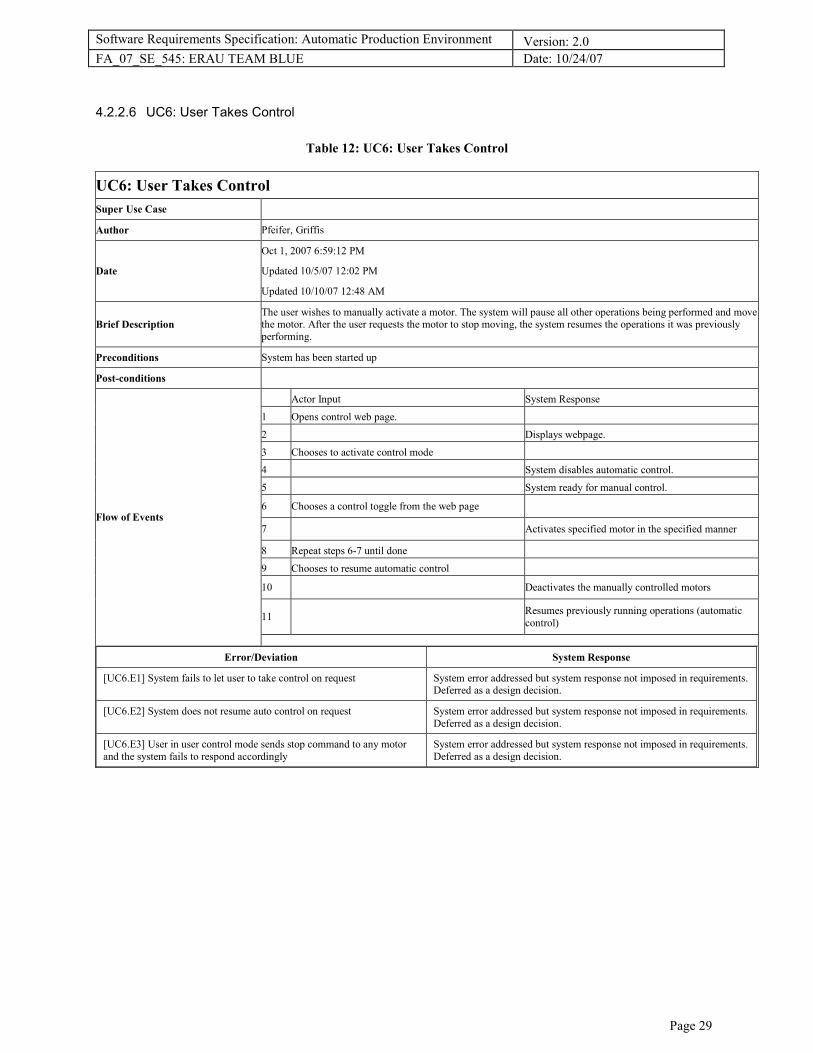
4.2.2.6 UC6: User Takes Control
Table 12: UC6: User Takes Control
UC6: User Takes Control
Super Use Case
Author Pfeifer, Griffis
Date
Oct 1, 2007 6:59:12 PM
Updated 10/5/07 12:02 PM
Updated 10/10/07 12:48 AM
Brief Description
The user wishes to manually activate a motor. The system will pause all other operations being performed and move the motor. After the user requests the motor to stop moving, the system resumes the operations it was previously
performing.
Preconditions System has been started up
Post-conditions
Actor Input System Response
1 Opens control web page.
2 Displays webpage.
3 Chooses to activate control mode
4 System disables automatic control.
5 System ready for manual control.
6 Chooses a control toggle from the web page
7 Activates specified motor in the specified manner
8 Repeat steps 6-7 until done
9 Chooses to resume automatic control
10 Deactivates the manually controlled motors
11
Resumes previously running operations (automatic
control)
Flow of Events
Error/Deviation System Response
[UC6.E1] System fails to let user to take control on request System error addressed but system response not imposed in requirements. Deferred as a design decision.
[UC6.E2] System does not resume auto control on request System error addressed but system response not imposed in requirements.
Deferred as a design decision.
[UC6.E3] User in user control mode sends stop command to any motor
and the system fails to respond accordingly
System error addressed but system response not imposed in requirements.
Deferred as a design decision.
Software Requirements Specification: Automatic Production Environment Version: 2.0
FA_07_SE_545: ERAU TEAM BLUE Date: 10/24/07
Page 30
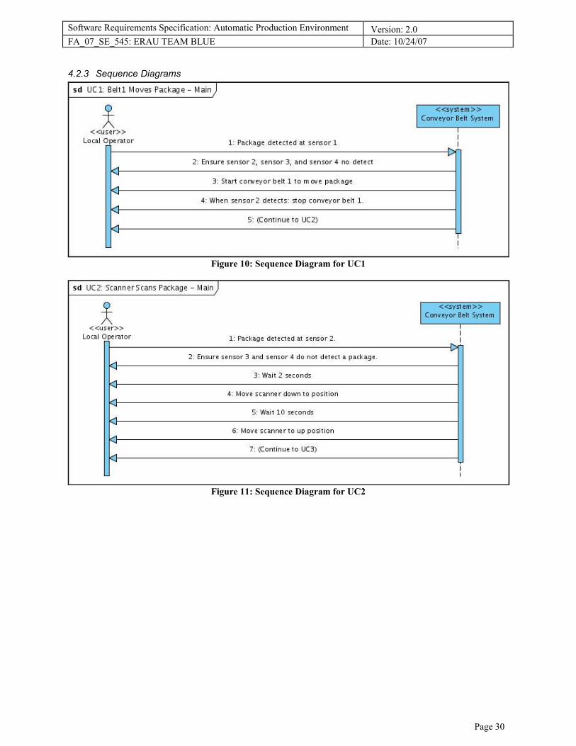
4.2.3 Sequence Diagrams
Figure 10: Sequence Diagram for UC1
Figure 11: Sequence Diagram for UC2

Software Requirements Specification: Automatic Production Environment Version: 2.0
FA_07_SE_545: ERAU TEAM BLUE Date: 10/24/07
Page 31
Figure 12: Sequence Diagram for UC3
Figure 13: Sequence Diagram for UC4
Figure 14: Sequence Diagram for UC5
Software Requirements Specification: Automatic Production Environment Version: 2.0
FA_07_SE_545: ERAU TEAM BLUE Date: 10/24/07
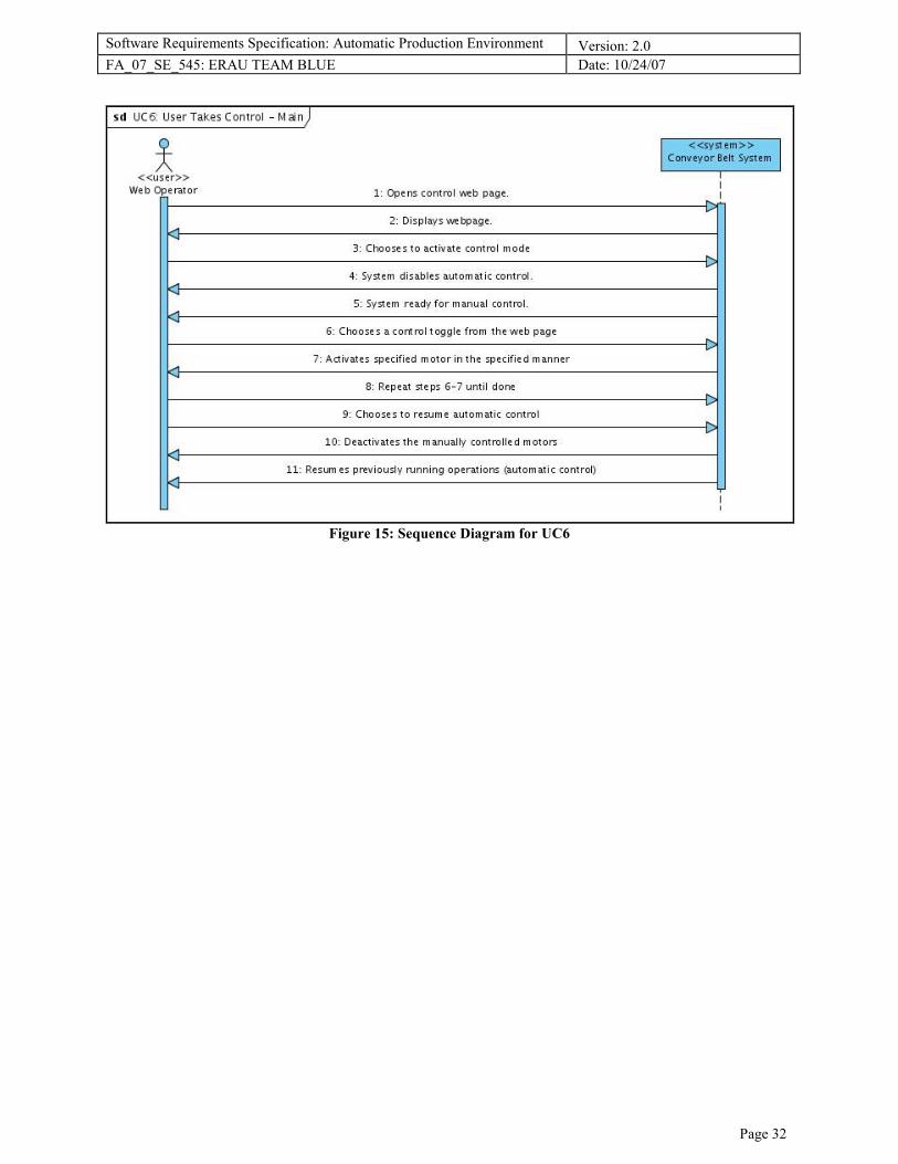
Page 32
Figure 15: Sequence Diagram for UC6
Software Requirements Specification: Automatic Production Environment Version: 2.0
FA_07_SE_545: ERAU TEAM BLUE Date: 10/24/07
Page 33
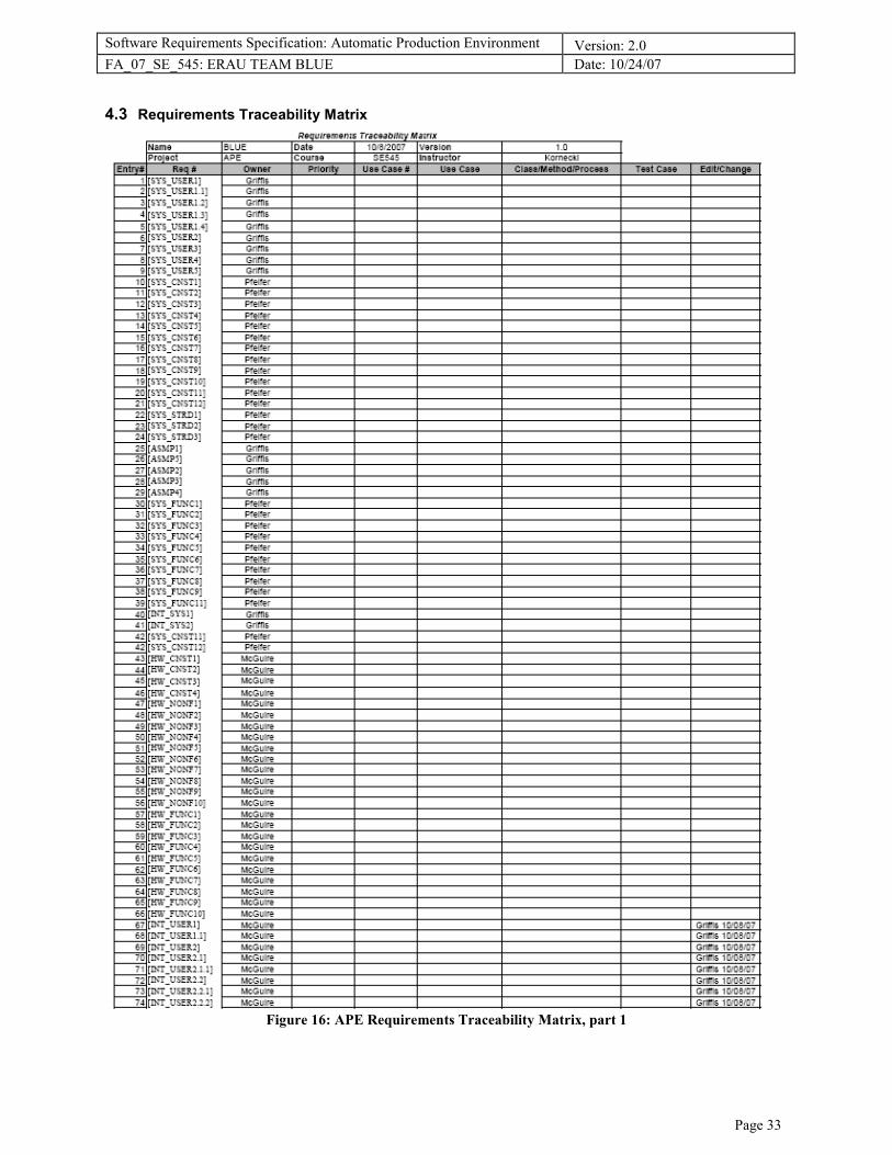
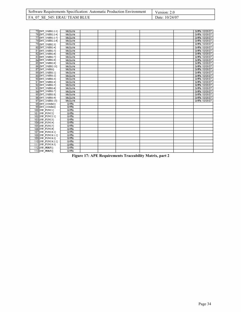
4.3 Requirements Traceability Matrix
Figure 16: APE Requirements Traceability Matrix, part 1
Software Requirements Specification: Automatic Production Environment Version: 2.0
FA_07_SE_545: ERAU TEAM BLUE Date: 10/24/07
Page 34
Figure 17: APE Requirements Traceability Matrix, part 2