specific absorption rate testing for a mobile phone in europe
TRANSCRIPT

Ilari Kinnunen
SPECIFIC ABSORPTION RATE TESTING FOR A MOBILE
PHONE IN EUROPE
SPECIFIC ABSORPTION RATE TESTING FOR A MOBILE PHONE IN EUROPE
Ilari Kinnunen Bachelor’s Thesis Spring 2019 Information Technology Oulu University of Applied Sciences

3
ABSTRACT
Oulu University of Applied Sciences Information Technology, Option of Device and Product design Author: Ilari Kinnunen Title of thesis: Specific Absorption Rate Testing for a Mobile Phone in Europe Supervisors: Timo Vainio, Miia Nurkkala Term and year of completion: Spring 2019 Pages: 35 + 2 appendices The topic for this thesis was commissioned by Verkotan Oy, a company working in the wireless industry providing testing and consulting services. The main ob-jective was to plan and conduct accredited SAR testing for a mobile phone to be sold in Europe. The work included clarifying the new regulations for LTE RF conducted power measurements and conducting them for all supported wireless technologies by the mobile phone, planning and conducting SAR testing, and writing test report. The objectives given for this thesis were accomplished. The new regulations for LTE SAR testing were clarified and conducted according to IEC PAS 63083:2017. RF conducted power measurements were done for LTE, GSM/GPRS, WCDMA and WLAN technologies. Test plan was created after the RF conducted power measurements and SAR testing for the mobile phone was conducted according to it. Test report was written from the testing including all necessary information required to repeat the measurements. Any information regarding the mobile phone is not shown in this thesis because of non-disclosure agreement.
Keywords: SAR testing, mobile phone, LTE, Europe

4
PREFACE
I would like to thank Verkotan Oy for hiring me as an intern and providing a
topic for this thesis.
Thanks to all my colleagues at Verkotan for providing a great working environ-
ment and special thanks for Miia Nurkkala, Kirsi Kyllönen and Sami Laukkanen
at Verkotan for your help through this process.
I would like to thank Kaija Posio from OUAS for helping with grammar of this
thesis and my supervisor Timo Vainio from OUAS for the advices during this
process.
Oulu, 21.2.2019 Ilari Kinnunen

5
CONTENTS
ABSTRACT 3
PREFACE 4
CONTENTS 5
VOCABULARY 7
1 INTRODUCTION 8
2 REGULATIONS FOR RADIO EQUIPMENT 9
2.1 Essential Requirements for Radio Equipment 9
2.2 Regulations for SAR testing 10
3 SPECIFIC ABSORPTION RATE 11
3.1 What is Specific Absorption Rate Testing? 11
3.2 SAR Requirements 11
3.2.1 Occupational and General Public Exposure 12
3.2.2 Basic Restrictions 12
3.3 System Checks 14
3.4 System Validations 16
4 RF CONDUCTED POWER MEASUREMENTS 17
4.1 Measurement Set-up for RF Conducted Power Measurements 17
4.2 LTE 18
4.2.1 Generating the Tables for RF Conducted Power Measurements 19
4.2.2 RF Conducted Power Measurements 20
4.3 Other Wireless Technologies 23
5 TEST PLAN 24
5.1 LTE 24
5.2 GSM/GPRS, WCDMA and WLAN 24
6 TEST PROCESS FOR SAR TESTING 25
6.1 SAR Test Set-up 25
6.2 Test Positions 26
6.2.1 Head Test Position 26
6.2.2 Body Test Position 27
6.3 SAR Testing for LTE Technology 28
6.3.1 Power Drift 29

6
6.4 SAR Testing for Other Wireless Technologies 29
6.5 Simultaneous Transmission 31
6.6 Reporting 31
7 CONCLUSIONS 32
REFERENCES 34
APPENDIX 1 36

7
VOCABULARY
DUT Device Under Test
EMF Electromagnetic Field
GPRS General Packet Radio Service
GSM Global System for Mobile Communications
LTE Long Term Evolution
MPR Maximum Power Reduction
QPSK Quadrature Phase Shift Keying
RB Resource Block
RF Radio Frequency
SAR Specific Absorption Rate
WCDMA Wideband Code Division Multiple Access
WLAN Wireless Local Area Network

8
1 INTRODUCTION
This thesis was commissioned by Verkotan Oy, a company working in the wire-
less industry providing testing and consulting services.
The objective of this thesis was to plan and conduct accredited SAR testing for
a mobile phone to be sold in Europe according to Radio Equipment Directive
and harmonised standards referenced within it and to implement IEC PAS
63083:2017 to processes of Verkotan Oy. The focus in this thesis will be on
LTE SAR testing since IEC PAS 63083:2017 has been released and it has new
regulations for LTE SAR testing in Europe.
The work includes clarifying the new regulations for LTE RF conducted power
measurements and conducting them for LTE, GSM/GPRS, WCDMA and WLAN
technologies, as well as planning the SAR measurements in advance and com-
pleting them. The test report is written from SAR testing including the test re-
sults and all necessary information to repeat the measurements.
The regulations and test processes included in mobile phone SAR testing will
be described in this document. Any information or results regarding the tested
device are not shown in this thesis because of the non-disclosure agreement.

9
2 REGULATIONS FOR RADIO EQUIPMENT
2.1 Essential Requirements for Radio Equipment
Radio Equipment Directive 2014/53/EU has regulations for radio equipment that
must be filled before they can enter the markets in Europe. There are three dif-
ferent essential requirements for a radio equipment set by Article 3 in Directive
2014/53/EU. SAR testing is included in the first part as “the protection of health
and safety of persons and of domestic animals and the protection of property”.
(1, p. L 153/72) The three essential requirements are shown below.
1. According to Directive 2014/53/EU, Article 3, radio equipment must be built in
a way to ensure that it meets the following regulations:
“a) the protection of health and safety of persons and of domestic animals and
the protection of property, including the objectives with respect to safety require-
ments set out in Directive 2014/35/EU, but with no voltage limit applying;
(b) an adequate level of electromagnetic compatibility as set out in Directive
2014/30/EU.” (1, p. L 153/72)
2. Radio equipment must also use and support the radio spectrum efficiently to
avoid adverse interference (1, p. L 153/72).
3. The following essential requirements are needed for radio equipment of cer-
tain categories or classes according to Directive 2014/53/EU, Article 3:
• Radio equipment interworks with accessories, in particular with common
chargers;
• Radio equipment interworks via networks with other radio equipment;
• Radio equipment can be connected to interfaces of the appropriate type
throughout the Union;

10
• Radio equipment does not harm the network or its functioning nor misuse
network resources, thereby causing an unacceptable degradation of ser-
vice;
• Radio equipment incorporates safeguards to ensure that the personal data
and privacy of the user and of the subscriber are protected;
• Radio equipment supports certain features ensuring protection from fraud;
• Radio equipment supports certain features ensuring access to emergency
services;
• Radio equipment supports certain features in order to facilitate its use by
users with a disability;
• Radio equipment supports certain features in order to ensure that software
can only be loaded into the radio equipment where the compliance of the
combination of the radio equipment and software has been demonstrated.
(1, p. L 153/72-L 153/73)
2.2 Regulations for SAR testing
There are harmonised standards under the Radio Equipment Directive
2014/53/EU that have regulations for SAR testing. Directive 2014/53/EU refer-
ences the standards EN 50360:2017 for products used next to the ear and EN
50566:2017 for products next to the body (1, p. C 326/114, C 326/115).
EN 50360:2017 refers to EN 62209-1:2016 and EN 50566:2017 to EN 62209-
2:2010 that provide more precise regulations for SAR testing of devices used
near head and body (2, p. 4; 3, p. 4).
Information from these standards and in addition from IEC PAS 63083:2017
were used to accomplish the SAR testing for a mobile phone. IEC PAS
63083:2017 is a publicly available specification published 2017-01 and it has
new regulations for LTE SAR testing in Europe (4, p. 6). The LTE modes for RF
conducted power measurements and test channels measured in SAR testing
are selected using a different method than for other wireless technologies.

11
3 SPECIFIC ABSORPTION RATE
3.1 What is Specific Absorption Rate Testing?
Specific absorption rate (SAR) testing measures the amount of RF energy ab-
sorbed by a human or animal body (5). SAR testing concerns wireless devices
that have radiating parts and intended use case within 20 cm of a body or head
(6, p. 8). A device under test (DUT) must be configured to the maximum power
state before SAR testing can be conducted to get the worst-case results. SAR
testing only gives the worst-case RF exposure results and not the ones users
usually get in normal circumstances. (5)
Exposure limits of SAR testing vary between different countries. Authorities
such as Federal Communications Commission (FCC), European Union (EU)
and Innovation, Science and Economic Development Canada (ISED) have reg-
ulations for SAR testing and SAR limits (7).
Liquid is used to simulate the human body or head tissue. SAR is measured
from the simulating liquid. (5) Peak spatial-average SAR is reported as W/kg
and it is an average of either 1g or 10 g tissue volume. The SAR limit in Europe
is 2.0 W/kg average measured from 10 g tissue volume. (8, p. 509)
SAR testing is done to ensure that the power transmitted by a wireless device
does not exceed the SAR limits. The SAR limits are set by experts of different
fields to be far below the RF exposure level that would have adverse health ef-
fects. (5)
3.2 SAR Requirements
Whole-body SAR between 1-4 W/kg increases the body temperature less than
1°C for resting humans during 30 minutes of EMF exposure according to an ex-
perimental evidence. Data acquired from animal experiments refer to similar re-
sults. Workers and volunteers agree with laboratory results that an increased
body temperature of 1°C can cause adverse biological effects. (8, p. 507)

12
Whole-body SAR values over 4 W/kg can result in an excessive amount of tis-
sue heating due to changes in thermoregulatory capacity of the body causing
harmful effects. The limit for irreversible effects caused by EMF exposure in
normal situations is more than 4 W/kg even for the most sensitive tissues. Ac-
cording to ICNIPR guidelines, “Many laboratory studies with rodent and nonhu-
man primate models have demonstrated the broad range of tissue damage re-
sulting from either partial-body or whole-body heating producing temperature
rises in excess of 1–2°C.” (8, p. 507)
There has not been a convincing evidence on studies that humans exposed to
typical levels of EMF exposure result in adverse reproductive effects or an in-
creased risk of cancer (8, p. 507).
3.2.1 Occupational and General Public Exposure
The occupational and general public exposure groups are defined in ICNIRP
guidelines as follows:
“The occupationally exposed population consists of adults who are generally ex-
posed under known conditions and are trained to be aware of potential risk and
to take appropriate precautions. By contrast, the general public comprises indi-
viduals of all ages and of varying health status, and may include particularly
susceptible groups or individuals.” (8, p. 508)
The general public population is usually unaware of the exposure to EMF and
because of that they are not able to protect themselves from the exposure. For
this reason, the exposure limit for general public is stricter. (8, p. 508)
3.2.2 Basic Restrictions
The amount of information about biological and health effects for humans or ex-
perimental animal caused by EMF exposure is limited and thus it is challenging
to set up a safe limit for the whole frequency range and modulations. Two differ-
ent general variables were taken into account when deciding the safety factors
for high-frequency fields according to ICNIRP guidelines:
13
• “Effects of EMF exposure under severe environmental conditions (high
temperature, etc.) and/or high activity levels; and
• the potentially higher thermal sensitivity in certain population groups, such
as the frail and/or elderly, infants and young children, and people with dis-
eases or taking medications that compromise thermal tolerance.” (8, p.
508)
The purpose of basic restrictions for frequencies between 100 kHz and 10 GHz
is according to ICNIRP guidelines to “prevent whole-body heat stress and ex-
cessive localized tissue heating” (8, p. 508).
The occupational exposure limit is based on studies and the whole-body aver-
age SAR limit is set at 0.4 W/kg, including a safe margin for exposure affecting
conditions. These conditions are, for example, the high ambient temperature,
humidity or physical level activity. (8, p. 507) The general public exposure limit
has additional safety factor of 5, and the whole-body average SAR limit is set to
0.08 W/kg (8, p. 509).
The localized SAR general public exposure limit for head and trunk was used in
mobile phone SAR testing and it is 2.0 W/kg averaged over 10 g tissue volume
(8, p. 509).
The localized SAR limit is based on animal experiments. The local SAR expo-
sure of 100 W/kg has been noticed to have adverse effects on rabbits’ eyes.
The safety factor of 50 was given for the general public exposure limit of local
SAR setting the limit to 2 W/kg averaged over 10 g of tissue volume. The local
SAR averaging over 10 g tissue volume is based on the approximate weight of
the human eye that is 10 g. (9, p. 8)
Whole-body SAR and local SAR significantly decreases when the separation
distance between the radiating device and the head or body is increased (8, p.
497). Basic restrictions set for the whole-body average SAR and the localized
SAR for head and trunk can be seen from the Figure 1 shown below (8, p. 508).

14
FIGURE 1. Basic restrictions (8, p. 509)
3.3 System Checks
System checks are part of SAR testing and they are done to make sure the test
set-up used in SAR measurements is working properly at the test frequencies
used. The repeatability of the test system is also measured at system checks.
The factors affecting the results of the system check according to EN 62209-
1:2016 are “incorrect liquid parameters, test system component failures, test
system component drift, operator errors in measurement set-up and measure-
ment parameter settings and other possible adverse conditions that may intro-
duce measurement errors, for example RF interference.” (10, p. 135)
The system check must be done with the same equipment and liquid used in
SAR testing and within 24 hours or before starting SAR testing. The system
check frequency must be within 100MHz from mid-band frequency of the tested
device with frequencies above 1GHz. When using frequencies below 1GHz, the
15
system check frequency must be within 10% of the mid-band frequency of the
tested device. (10, p. 136)
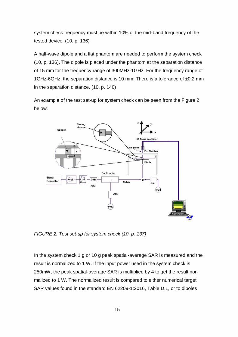
A half-wave dipole and a flat phantom are needed to perform the system check
(10, p. 136). The dipole is placed under the phantom at the separation distance
of 15 mm for the frequency range of 300MHz-1GHz. For the frequency range of
1GHz-6GHz, the separation distance is 10 mm. There is a tolerance of ±0.2 mm
in the separation distance. (10, p. 140)
An example of the test set-up for system check can be seen from the Figure 2
below.
FIGURE 2. Test set-up for system check (10, p. 137)
In the system check 1 g or 10 g peak spatial-average SAR is measured and the
result is normalized to 1 W. If the input power used in the system check is
250mW, the peak spatial-average SAR is multiplied by 4 to get the result nor-
malized to 1 W. The normalized result is compared to either numerical target
SAR values found in the standard EN 62209-1:2016, Table D.1, or to dipoles

16
calibration values. The system check is a pass if the result is within ±10% of the
target values. (10, p. 138)
3.4 System Validations
System validation is done to verify the accuracy and performance of the meas-
urement system with a comprehensive set of testing. It is required when the
measurement system has a new part or when modifications have been made to
the test system. System validation is needed for example when a new dipole is
taken into use or when the old dipole has been calibrated. A probe with valid
calibration needs to be used for system validation. (10, p. 139)
System validation starts with the same 1 g or 10 g peak spatial-average SAR
measurement done in the system check. The peak spatial-average SAR needs
to be within ±10% of either numerical target SAR values found at EN 62209-
1:2016, Table D.1, or dipoles calibration values. System validation also has ad-
ditional measurements to check the linearity of SAR values with e.g. different in-
put powers and digital modulations. (10, p. 140-141)

17
4 RF CONDUCTED POWER MEASUREMENTS
RF conducted power measurements are done to determine the maximum
power in each frequency band and operating mode and to select the worst-case
test configuration for SAR testing (10, p. 25).
RF conducted power measurements of LTE technology in Europe have new
regulations set by IEC PAS 63083:2017.
4.1 Measurement Set-up for RF Conducted Power Measurements
RF conducted power measurements were done with the Anritsu MT8820C radio
communication analyzer using a calibrated RF cable with a 10dB attenuator for
GSM/GPRS, WCDMA and LTE technologies. The loss of the RF cable including
the attenuator and the cables attached to DUT were removed from the results
afterwards. The test set-up for RF conducted measurements can be seen from
Figure 3.
FIGURE 3. Test set-up for GSM/GPRS, WCDMA and LTE RF conducted power
measurements (11)
10dB DUT Attenuator
Anritsu MT8820C
Radio Communication Analyzer
18
RF conducted power from WLAN channels were measured without Anritsu ra-
dio communication analyzer. A software on the mobile phone was used to set
the different configurations and channels because similar loopback modes are
not available for WLAN 802.11 protocols that were used, for example, in LTE
testing (12, p. 3). R&S NRP-Z81 power meter with 10dB attenuator was used to
measure the RF conducted power of WLAN channels. Attenuation was taken
into account in the final results.
4.2 LTE
Different LTE mode and SAR test configuration combinations can be hundreds
because of complexity in the LTE technology. According to IEC PAS
63083:2017, the LTE mode consists of “Frequency band, channel bandwidth
(from 1.4 MHz to 20 MHz), modulation (QPSK and 16- QAM), number of re-
source blocks allocated, offset of the resource blocks within the channel band-
width as well as MPR.” (4, p. 7)
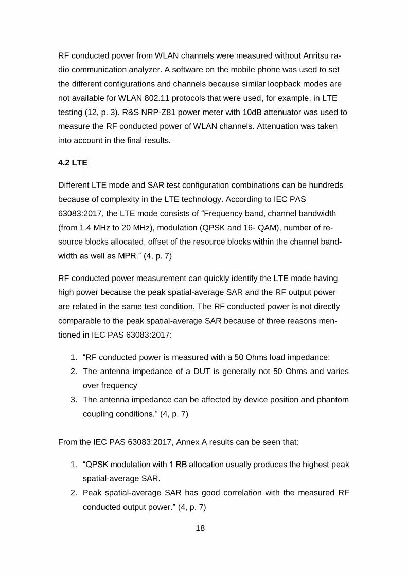
RF conducted power measurement can quickly identify the LTE mode having
high power because the peak spatial-average SAR and the RF output power
are related in the same test condition. The RF conducted power is not directly
comparable to the peak spatial-average SAR because of three reasons men-
tioned in IEC PAS 63083:2017:
1. “RF conducted power is measured with a 50 Ohms load impedance;
2. The antenna impedance of a DUT is generally not 50 Ohms and varies
over frequency
3. The antenna impedance can be affected by device position and phantom
coupling conditions.” (4, p. 7)
From the IEC PAS 63083:2017, Annex A results can be seen that:
1. “QPSK modulation with 1 RB allocation usually produces the highest peak
spatial-average SAR.
2. Peak spatial-average SAR has good correlation with the measured RF
conducted output power.” (4, p. 7)

19
3. Highest SAR results are highly unlikely to be expected for LTE mode with
conducted power less than 85% of maximum conducted power measured
among all LTE modes in the frequency band (4, p. 7).
4.2.1 Generating the Tables for RF Conducted Power Measurements
IEC PAS 63083:2017 has regulations on what LTE modes need to be meas-
ured in RF conducted power measurements. The tables for each LTE frequency
band used in Europe were generated according to these rules. The operation
mode of QPSK-modulation and 1 RB allocation is measured at the highest
bandwidth of every frequency band. When the number of channels within the
frequency band is one, the 1 RB offset within the channel bandwidth is allocated
at the centre. For the frequency band with 3 channels, the 1 RB offset within the
channel bandwidth is allocated at 0, centre and max. (4, p. 7-8)
In addition, other LTE modes with the different channel bandwidth, modulation
and number of RBs according to the Table 1 and Table 2 below need to be
measured. Configurations of the Table 1 are used when MPR does not apply. In
this case the RB offset for low and middle channels is set to 0 and for the high
channel to max. MPR does not apply when the modulation used is QPSK and 1
RB is allocated. (4, p. 8)
TABLE 1. MPR does not apply (4, p. 19)

20
In the Table 2 when MPR applies the RB offset for the low channel is set to
max. For the middle channel the RB offset is set to 0 and max, and for the high
channel the RB offset is set to 0. (4, p. 8)
TABLE 2. MPR applies (4, p. 19)
4.2.2 RF Conducted Power Measurements
The LTE mode tables for RF conducted power measurements were generated
with Python script based on the IEC PAS 63083:2017 regulations with the help
of an experienced programmer working in the company. The generated LTE
mode tables of LTE bands 3, 7, 20 were compared to the Table E.1, Table E.2
and Table E.3 shown in IEC PAS 63083:2017, Annex E, to make sure the py-
thon script is working correctly. The LTE mode table generated for the LTE
band 1 is available in the Appendix 1.
21
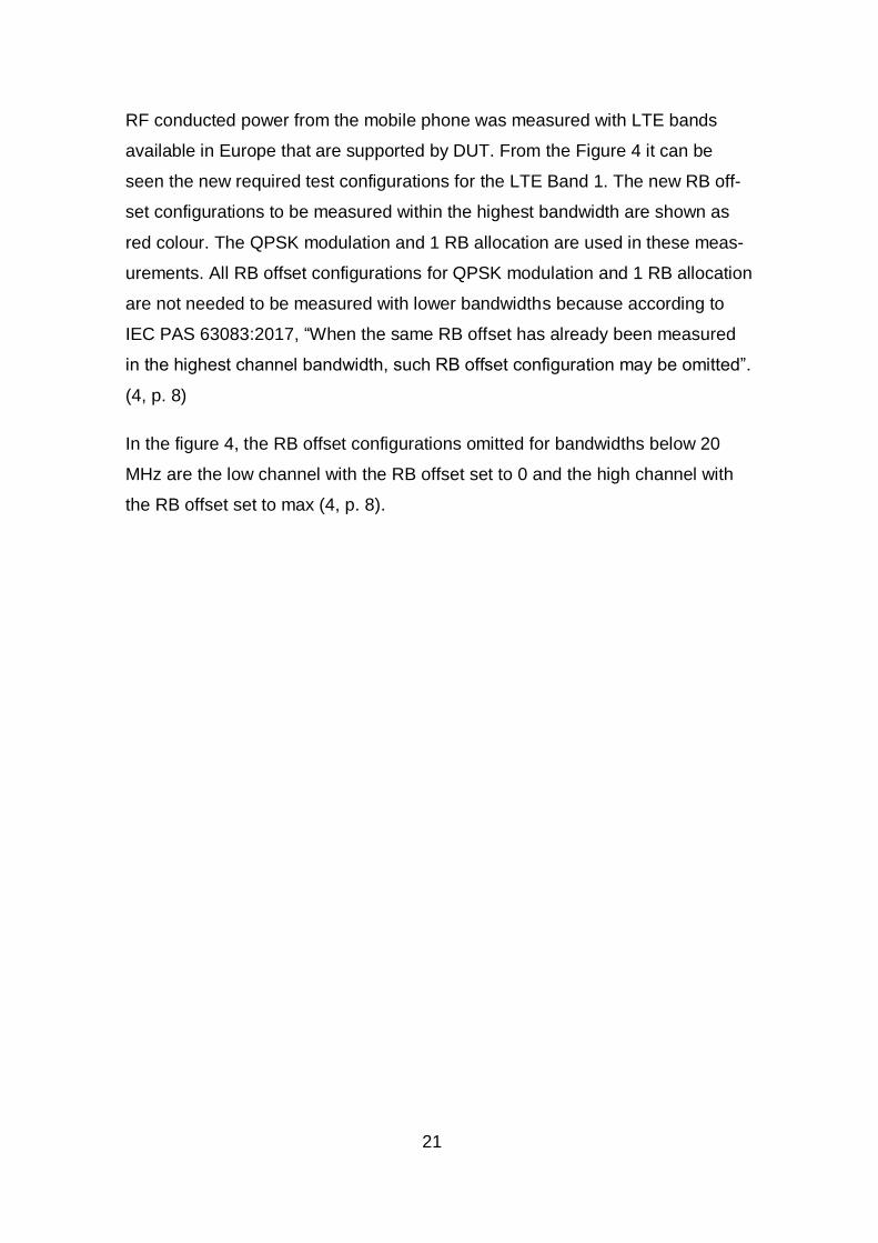
RF conducted power from the mobile phone was measured with LTE bands
available in Europe that are supported by DUT. From the Figure 4 it can be
seen the new required test configurations for the LTE Band 1. The new RB off-
set configurations to be measured within the highest bandwidth are shown as
red colour. The QPSK modulation and 1 RB allocation are used in these meas-
urements. All RB offset configurations for QPSK modulation and 1 RB allocation
are not needed to be measured with lower bandwidths because according to
IEC PAS 63083:2017, “When the same RB offset has already been measured
in the highest channel bandwidth, such RB offset configuration may be omitted”.
(4, p. 8)
In the figure 4, the RB offset configurations omitted for bandwidths below 20
MHz are the low channel with the RB offset set to 0 and the high channel with
the RB offset set to max (4, p. 8).

22
FIGURE 4. Measured and omitted RB offset configurations on the LTE band 1
(4, p. 9)

23
4.3 Other Wireless Technologies
There are no regulations in SAR standards for the RF conducted measure-
ments for other wireless technologies than LTE. RF Conducted power measure-
ments are done in the same way for GSM/GPRS and WCDMA. The only differ-
ence with GPRS technology is that the measured RF conducted power results
are changed to time-averaged power and the SAR testing is conducted with the
maximum time averaged power slot configuration (10, p. 25).
RF conducted power from the mobile phone was measured from GSM/GPRS,
WCDMA and WLAN frequency bands it supports in Europe.

24
5 TEST PLAN
A test plan for SAR testing was created according to the results of RF con-
ducted power measurements of mobile phone. The test plan includes all test
configurations measured in SAR testing making it easier to continue with SAR
testing. The test configurations for LTE was selected using a different method
than for GSM/GPRS, WCDMA and WLAN because of the new regulations.
5.1 LTE
All test positions are measured at all supported frequency bands with the chan-
nel and LTE mode having the highest RF conducted power. The measured
channel can be either a low, middle or high channel. Other channels are meas-
ured with the LTE mode having the highest RF conducted power on each chan-
nel and on the test position having the highest reported SAR result. (4, p. 10)
For example, if the low channel of frequency band has the highest RF con-
ducted power, all test positions are measured at that channel with the LTE
mode having the highest RF conducted power. The middle channel is measured
with the LTE mode having the highest RF conducted power in the middle chan-
nel and at the test position having the highest reported SAR result for the low
channel. The high channel would be measured using the same method than the
middle channel. All different LTE modes and test positions to be tested within all
supported frequency bands were added to the test plan.
5.2 GSM/GPRS, WCDMA and WLAN
The operating mode having the highest RF conducted power was selected for
SAR testing for each wireless technology and frequency band. SAR testing for
GSM/GPRS, WCDMA and WLAN is always started from the middle channel
and all test positions are measured at that channel. The test position having the
highest reported SAR result is measured at low and high channels using the
same operating mode than for the middle channel. All test configurations to be
tested within all supported frequency bands were added to the test plan. (10, p.
34)

25
6 TEST PROCESS FOR SAR TESTING
6.1 SAR Test Set-up
The SAR test set-up consists of a PC, an DASY5-robot and a phantom. The ro-
bot has a measurement probe that is used to measure the SAR values from the
tissue simulating liquid inside the phantom. DASY5 software is used on the PC
to, for example, create the test configurations, install the different equipment
and liquid used in measurements. The SAM phantom is used for mobile phone
SAR testing because it is needed for the testing of the head test positions. It
also has a flat part in the middle that is used in testing of the body test positions.
The SAR test set-up can be seen in the Figure 5.
FIGURE 5. SAR test set-up (13, p. 11-1)
The RF signal was fed to the chamber from the Anritsu MT8820C radio commu-
nication analyzer through RF cables as shown in the Figure 6. This test set-up
was used for SAR testing of GSM/GPRS, WCDMA and LTE. The antenna was
used to make the connection between the radio communication analyzer and

26
the mobile phone. The mobile phone was placed under the phantom in the SAR
chamber and the DASY5-robot was used to measure the results.
FIGURE 6. Connection from the Radio Communication Analyzer to DUT (11)
SAR testing of WLAN had some differences to testing of GSM/GPRS and
WCDMA. WLAN transmission has random characteristics and needs to be con-
figured before SAR testing. A software on a mobile phone was used to config-
ure different WLAN test modes, for example setting the maximum output power
and enabling continuous transmission. Similar loopback modes are not availa-
ble for WLAN 802.11 protocols that were used, for example, in LTE testing. The
Anritsu radio communication analyzer was not used because of this reason in
SAR testing of WLAN. (12, p. 3)
6.2 Test Positions
6.2.1 Head Test Position
In head SAR testing, cheek and tilt positions are measured on the left and right
side of the SAM phantom. In cheek position the mobile phone is placed under
the phantom in a way that the middle part of the acoustic output touches the
centre of ear. The mobile phone is then rotated in a way that the vertical centre
line goes through the phone in the middle of it. The mobile phone is then lifted
against the phantom so that the ear and cheek touch it. The definitions on how
to place the mobile phone under the phantom for cheek position are explained
fully in EN 62209-1:2016, 6.2.4.2. Cheek test position is shown in the Figure 7.
(10, p. 28)
Antenna DUT Over the air connection
Radio Communication Analyzer SAR chamber Anritsu MT8820C

27
FIGURE 7. Cheek position (10, p. 30)
In tilt position, the angle is increased by 15 degrees and other changes are not
made compared to cheek test position. The definitions how to place the mobile
phone under the phantom for tilt position are explained fully in EN 62209-
1:2016, 6.2.4.3. Tilt test position is shown in the Figure 8. (10, p. 32)
FIGURE 8. Tilt position (10, p. 32)
6.2.2 Body Test Position
In SAR testing of body test position, the back and front side of the mobile phone
are measured in the middle of the flat part of the SAM phantom as shown in the
Figure 9 (6, p. 24). The mobile phone is lifted until the separation distance of
5mm is reached between the mobile phone and the bottom of the phantom (3,
p. 5).

28
FIGURE 9. Front and back test position (6, p. 24)
6.3 SAR Testing for LTE Technology
SAR testing was carried out according to the test plan created. The measured
SAR results were scaled with the formula 10((Maximum power – Conducted power)/10) to get
the reported SAR result. This takes into account the difference between tune-up
specifications and production variations given by the DUT manufacturer, and
the actual measured conducted power of the device that was used in testing.
(10, p. 25)
The reported SAR result was, according to the IEC PAS 63083:2017 Approach
1, multiplied by 1.35 and if the result was below the SAR limit of 2.0 W/kg, no
more measurements were needed. The Approach 1 is the simplest way as it
does not require more SAR testing. If the result is above the limit with this ap-
proach, IEC PAS 63083:2017 has two other approaches. (4, p. 11)
According to the Approach 2, all LTE modes that have RF conducted power
equal to or over 85% from the maximum measured one in that frequency band,
are measured at the test position where the SAR result surpasses the limit (4, p.
11).
According to the Approach 3, the LTE mode with the second highest RF con-
ducted power in that frequency band is measured at the test position where the
SAR result surpasses the limit. The reported SAR result is multiplied by 1.35
and if the result is below the 2.0 W/kg limit, no more measurements are needed.

29
If the result is over the limit, the same procedure is repeated until the results are
below the required limit. (4, p. 11)
If the reported SAR result with any wireless technology is within 3dB of the SAR
limit, all channels must be measured from that frequency band (10, p. 41).
6.3.1 Power Drift
When the power drift in the SAR measurement exceeds ±5%, the power drift
can be considered in the measurement results to provide more accurate SAR
results (10, p. 38). The formula used to include the power drifts in reported SAR
result is 10((Maximum power – (Conducted power – Power drift))/10) where the power drift must be
changed to positive.
6.4 SAR Testing for Other Wireless Technologies
SAR testing for other wireless technologies, including GSM/GPRS, WCDMA
and WLAN, were performed according to the standards EN 62209-1:2016 and
EN 62209-2:2010. SAR testing was conducted according to the test plan cre-
ated earlier. The reported SAR result is calculated in the same way than for the
LTE technology. Head and body test positions are the same for all wireless
technologies. The different approaches used in LTE SAR testing and the earlier
mentioned IEC PAS 63083:2017 are not used for other wireless technologies.
The Figure 10 shows the measurement process used in SAR testing of head
test position for all wireless technologies except LTE. First, the wireless technol-
ogy and the frequency band is chosen. The operating mode having the highest
RF conducted power is selected for SAR measurements. SAR testing is started
at the middle channel and all test positions including cheek and tilt on the left
and right side of the phantom are measured. Low and high channels of the se-
lected frequency band are measured at the test position having the highest re-
ported SAR result and with the same operating mode as the middle channel.
(10, p. 36)

30
FIGURE 10. Measurement process (10, p. 36)
One SAR measurement consists of four different measurements. In the SAR
reference measurement, the power from the DUT is measured. The area scan
is done to measure the whole area covered by the DUT. The zoom scan is a
more precise measurement that measures a small cube around the maximum
SAR measured during the area scan. The last measurement is the SAR drift
measurement, measuring the power from the DUT in the same way than the
31
SAR reference measurement. The SAR reference measurement and the SAR
drift measurement are compared to see if the power has drifted during the
measurement. The same procedure is done with all test positions and wireless
technologies for mobile phone testing.
6.5 Simultaneous Transmission
Typically, it is possible for WLAN and one of the cellular technologies to be op-
erated simultaneously (10, p. 41). For each different test position, the highest
reported SAR result was selected from cellular technologies. The same was
done for WLAN and the highest cellular reported SAR result and the highest
WLAN reported SAR result were summed, assuming the antennas are co-lo-
cated, to see if the simultaneous SAR is over the limit of 2.0 W/kg. If the simul-
taneous SAR was over the limit, two results were summed again using Com-
bined Fast SAR of SEMCAD X software. The reason why the software is used
is because the hot spots of the two summed measurements may not be exactly
on top of each other so when the results are summed with the software, the
simultaneous SAR result is can be smaller. The results after summed with Com-
bined Fast SAR are either pass or fail.
6.6 Reporting
All test results are documented in test reports and the testing must be fully re-
peatable with the information included in test reports. This includes DUT config-
urations and test positions, system calibrations and measurement uncertainty
limits. There are 5 different minimum requirements to be reported in test reports
according to EN 62209-2:2010: General introduction, measurement system, un-
certainty estimation, device and test details, and report summary. The ISO/IEC
17025:2005 standard has detailed guidelines of what information must be in-
cluded in test reports. (6, p. 64-65)

32
7 CONCLUSIONS
The main objective was to plan and conduct accredited SAR testing for mobile
phone to be sold in Europe and implement the new LTE regulations from IEC
PAS 63083:2017 to processes of Verkotan Oy.
The work included clarifying the new regulations for LTE RF conducted power
measurements according to the regulations of IEC PAS 63083:2017 and con-
ducting them for LTE, GSM/GPRS, WCDMA and WLAN technologies, creating
a test plan for SAR testing, conducting SAR testing for a mobile phone and writ-
ing the test report including the test results and all necessary information to re-
peat the measurements.
The mobile phone SAR testing was completed, and other objectives were ac-
complished as well. The new regulations for LTE RF conducted power meas-
urements were clarified and conducted according to the regulations of IEC PAS
63083:2017. The new regulations were also implemented to the processes of
Verkotan Oy. RF conducted power measurements were completed for other
wireless technologies, including GSM/GPRS, WCDMA and WLAN. The test
plan was created, and SAR testing for the mobile phone was conducted accord-
ing to this plan for LTE, GSM/GPRS, WCDMA and WLAN technologies. The
test report was written including the SAR test results and information required
for repeatability.
IEC PAS 63083:2017 has new regulations regarding RF conducted power
measurements and SAR testing of the LTE technology. New LTE modes were
added to the RF conducted power measurements when compared to the old
regulations. On RF conducted power measurements, some of the LTE modes
located at the edge of the channel may be omitted if they have already been
measured at the highest channel bandwidth. SAR testing for the LTE technol-
ogy is started using the channel and LTE mode having the highest RF con-
ducted power within the frequency band. Other channels are measured using
the LTE mode having the highest RF conducted power on each one and at the
test position having the highest reported SAR result.

33
Plenty of new information was learned regarding overall SAR testing knowledge
during the thesis. This included the test positions for a mobile phone used in
SAR testing and how to place the mobile phone under the phantom. RF con-
ducted power measurements were a new task, including the set-up as well as
conducting them. Wireless technologies, such as GSM/GPRS, WCDMA, WLAN
and LTE, are more familiar and during the thesis, it was learned how they are
tested. The new LTE regulations for SAR testing clarified during this thesis will
help the company as it is easier to do more LTE SAR testing for devices to be
sold in Europe in the future.

34
REFERENCES
1. The Radio Equipment Directive 2014/53/EU. 2014. Official Journal of the Eu-
ropean Union, p. C 326/114, C 326/115, L 153/72, L 153/73
2. EN 50360:2017. 2017. Product standard to demonstrate the compliance of
wireless communication devices, with the basic restrictions and exposure limit
values related to human exposure to electromagnetic fields in the frequency
range from 300 MHz to 6 GHz: devices used next to the ear, p. 4.
3. EN 50566:2017. 2017. Product standard to demonstrate the compliance of
wireless communication devices with the basic restrictions and exposure limit
values related to human exposure to electromagnetic fields in the frequency
range from 30 MHz to 6 GHz: hand-held and body mounted devices in close
proximity to the human body, p. 4, 5.
4. IEC PAS 63083:2017. 2017. Specific absorption rate (SAR) measurement
procedure for long term evolution (LTE) devices, p. 7-11, 19.
5. FCC. 2018. Specific Absorption Rate (SAR) For Cell Phones: What It Means
For You. Date of retrieval: 3.12.2018.
https://www.fcc.gov/consumers/guides/specific-absorption-rate-sar-cell-phones-
what-it-means-you.
6. EN 62209-2:2010. 2010. Human exposure to radio frequency fields from
hand-held and body-mounted wireless communication devices - Human mod-
els, instrumentation, and procedures - Part 2: Procedure to determine the spe-
cific absorption rate (SAR) for wireless communication devices used in close
proximity to the human body (frequency range of 30 MHz to 6 GHz), p. 8, 24,
64-65.
7. Verkotan. 2019. SAR Testing. Date of Retrieval: 9.2.2019.
https://verkotan.com/sar-testing/.

35
8. ICNIRP guidelines. 1998. For limiting exposure to time-varying electric, mag-
netic and electromagnetic fields (Up to 300 GHz), p. 507-509.
9. D. Sánchez-Hernández. 2009. High Frequency Electromagnetic Dosimetry,
London: Artech House, p. 8.
10. EN 62209-1:2016. 2016. Measurement procedure for the assessment of
specific absorption rate of human exposure to radio frequency fields from hand-
held and body-mounted wireless communication devices - Part 1: Devices used
next to the ear (Frequency range of 300 MHz to 6 GHz), p. 25, 28, 30, 32, 34,
36, 38, 41, 135-141.
11. Anritsu. 2019. Radio Communication Analyzer MT8820C. Date of retrieval:
28.12.2018.
https://www.anritsu.com/en-us/test-measurement/products/mt8820c.
12. 248227 D01 802.11 Wi-Fi SAR v02r02. 2015. SAR guidance for IEEE
802.11 (Wi-Fi) transmitters, p. 3.
13. Speag. 2014. DASY52 System handbook, p. 11-1.

APPENDIX 1/1
APPENDIX 1
LTE Band
BW (MHz) RBs
RB Start Modulation
Channel Type Channel
Frequency (MHz)
1 20 1 0 QPSK LOW CH 18100 1930
1 20 1 49 QPSK LOW CH 18100 1930
1 20 1 99 QPSK LOW CH 18100 1930
1 20 18 0 QPSK LOW CH 18100 1930
1 20 100 0 QPSK LOW CH 18100 1930
1 20 18 82 16QAM LOW CH 18100 1930
1 20 100 0 16QAM LOW CH 18100 1930
1 20 1 0 QPSK MID CH 18300 1950
1 20 1 49 QPSK MID CH 18300 1950
1 20 1 99 QPSK MID CH 18300 1950
1 20 18 0 QPSK MID CH 18300 1950
1 20 100 0 QPSK MID CH 18300 1950
1 20 18 0 16QAM MID CH 18300 1950
1 20 18 82 16QAM MID CH 18300 1950
1 20 100 0 16QAM MID CH 18300 1950
1 20 1 0 QPSK HIGH CH 18500 1970
1 20 1 49 QPSK HIGH CH 18500 1970
1 20 1 99 QPSK HIGH CH 18500 1970
1 20 18 82 QPSK HIGH CH 18500 1970
1 20 100 0 QPSK HIGH CH 18500 1970
1 20 18 0 16QAM HIGH CH 18500 1970
1 20 100 0 16QAM HIGH CH 18500 1970
1 15 16 0 QPSK LOW CH 18075 1927.5
1 15 75 0 QPSK LOW CH 18075 1927.5
1 15 16 59 16QAM LOW CH 18075 1927.5
1 15 75 0 16QAM LOW CH 18075 1927.5
1 15 1 0 QPSK MID CH 18300 1950
1 15 16 0 QPSK MID CH 18300 1950
1 15 75 0 QPSK MID CH 18300 1950
1 15 16 0 16QAM MID CH 18300 1950
1 15 16 59 16QAM MID CH 18300 1950
1 15 75 0 16QAM MID CH 18300 1950
1 15 16 59 QPSK HIGH CH 18525 1972.5
1 15 75 0 QPSK HIGH CH 18525 1972.5
1 15 16 0 16QAM HIGH CH 18525 1972.5
1 15 75 0 16QAM HIGH CH 18525 1972.5
1 10 12 0 QPSK LOW CH 18050 1925
1 10 50 0 QPSK LOW CH 18050 1925
1 10 12 38 16QAM LOW CH 18050 1925
1 10 50 0 16QAM LOW CH 18050 1925
1 10 1 0 QPSK MID CH 18300 1950

APPENDIX 1/2
1 10 12 0 QPSK MID CH 18300 1950
1 10 50 0 QPSK MID CH 18300 1950
1 10 12 0 16QAM MID CH 18300 1950
1 10 12 38 16QAM MID CH 18300 1950
1 10 50 0 16QAM MID CH 18300 1950
1 10 12 38 QPSK HIGH CH 18550 1975
1 10 50 0 QPSK HIGH CH 18550 1975
1 10 12 0 16QAM HIGH CH 18550 1975
1 10 50 0 16QAM HIGH CH 18550 1975
1 5 8 0 QPSK LOW CH 18025 1922.5
1 5 25 0 QPSK LOW CH 18025 1922.5
1 5 8 17 16QAM LOW CH 18025 1922.5
1 5 25 0 16QAM LOW CH 18025 1922.5
1 5 1 0 QPSK MID CH 18300 1950
1 5 8 0 QPSK MID CH 18300 1950
1 5 25 0 QPSK MID CH 18300 1950
1 5 8 0 16QAM MID CH 18300 1950
1 5 8 17 16QAM MID CH 18300 1950
1 5 25 0 16QAM MID CH 18300 1950
1 5 8 17 QPSK HIGH CH 18575 1977.5
1 5 25 0 QPSK HIGH CH 18575 1977.5
1 5 8 0 16QAM HIGH CH 18575 1977.5
1 5 25 0 16QAM HIGH CH 18575 1977.5