specialist grouting - keller ground...
TRANSCRIPT

SpecialistGrouting

2 3
GROUTING SOLUTIONS
GROUND MODIFICATION SOLUTIONS
APPLICATIONS SOILFRAC® SOILCRETE® PERMEATION COMPACTION INFILL
Ground Water Control
Underpinning
Settlement Control
Ground Strengthening/ Consolidation
Settlement Reversal
Void Grouting
Dam Grouting
Excavation Support
Leachate Control
Mine&ShaftInfilling
Pile Base & Shaft Grouting
Piping Failure Control
Sealing Slabs
Solution Features
Swallow Holes
Shaft Bases
Tunnelling Support
Underslab Grouting
Liquefaction Prevention
Ground Compaction
Foundation Support
K E L L E R M E E T S YO U R E N G I N E E R I N G N E E D SKeller Ground Engineering has
sixty years grouting experience.
Whether a common application
or one that draws upon our
unparalleled experience and
creativity throughout Australia,
New Zealand and the South
Pacific we assist engineers,
contractors and owners with
identifying and implementing
the right solution from outline
concept to detailed design and
execution for any situation.
100
80
60
40
20
00,60,002 0,006 0,02 0,06 6,0 20 600,2 2,0
Clay Silt Sand Gravel
]%[
thgiew
yb
gnissaP
Grain size [mmØ]
Synthetic SolutionsSodium Silicate
[lv]Solutions
Compaction Grouting
Micro fine Cement
General Cement
Soil Frac
optimal
can be used in exceptional circumstances
less optimal
Soilcrete - Jet Grouting®
Cobbles
LIMITS FOR GROUTING TECHNIQUES:

4 5
Super Jet monitor and nozzle.
SOILCRETE® JET GROUTING
T H E P R O C E S S
Jet Grouting is a Ground Modification System used to create insitu, cemented formations of soil. Using high velocity (>100m/s) cutting jets of water or cement suspension (grout) the system erodes and insitu mixes the soil to form the soil grout composite material.
Soilcrete® Jet Grouting can be carried out using three different systems. The choice of method is determined by the soil conditions, the required geometry, the required Soilcrete® parameters and the application.
T H E P R O P E RT I E S
The compressive strength of Soilcrete® is a function of the cement content of the grout and grading of the portion of soil within the Soilcrete® mass.
The permeability and strength of the Soilcrete® can be controlled by the addition of additives to the grout mix.
Type of Soil Silt or Clay Sand Gravel
UCS (MPa) <5 <10 <20
SOILCRETE® JET GROUTING
D E S I G N A N D Q UA L I T Y CON T R O L
Soilcrete® Jet Grouting can be designed to mix or almost fully replace a soil with grout. For the common application of underpinning, excavation support and groundwater cut-off the design consists of developing a continuous Soilcrete® mass to resist over turning and sliding whilst maintaining the integrity of supported structures or utilities.
For retaining structures design checks are made for the competency of the soils below the base for bearing and settlement together with an evaluation of the internal shear and bending stresses in the Soilcrete®. The strength of the Soilcrete® is a function of the insitu soils and strength variations are to be expected, for this reason a factor of safety of 2.5 to 3.0 is typically applied for an average allowable strength.
The size of the Soilcrete® mass to be created is dictated by the application, a variety of geometries can be achieved. The width or diameter of each panel or column is determined during the design stage. Reliable descriptions of the soil composition and strength or density allows thisassessmenttobemadewithconfidence.
Excavated 5.0m Super Jet Column.
Single System: Single System operates with a grout jet for simultaneous cutting and mixing of the soil. The Single System is used for small to medium sized Soilcrete® columns in low density soils.
Double System: The Double System uses a compressed air shroud around the jet nozzle to increase the erosion capability of the jet. The Double System is used in dense soils, installing panel walls, underpinning and mass treatment.
Grout Backflow
Grout jet
Backflow
Air shroudedgrout jet
AirGrout
Backflow
Air shroudedgrout jet
Air
GroutWater
Grout jet
Triple System: Typically used for underpinning and in sensitive or highly variable soils, the Triple system erodes the soil with an air shrouded water jet and simultaneously injects grout into the eroded soil through an additional nozzle.
7 28
25
14 42210
50
75
100
Setting time [days]
Compressive strength in % of the final strength
non-cohesivesoil
cohesive soil
Development of Soilcrete® Strength with time
CON S T RU C T I ON S E Q U E N C E
Soilcrete® Jet Grouting equipment consists of a high pressure pumping unit, cement mixing equipment, storage silo and stores containers.
The grout mixing and pumping unit is connected to the drill rig with high pressure hoses and control cables allowing remote location of the plant. The jetting process can be performed using a wide range of drilling rigs with mast heights varyingfrom2.5mto35.0m.Theboreholesarenormallycontainedinshallowtrenchesusedtodirecttheflowoftheexcess soil-water-cement spoil to tanks or settling ponds.
1. DrillingDrillrodsfittedwithjetnozzlesareboredtothefinaldepth using grout to stabilize the hole. Jetting commences at the base of the hole.
2. GroutingTurbulence caused by the jet results in the uniform mixing of grout and soil. Excess water, soil and grout returns to the surface through the space between the drill rod and borehole wall.
3. ContinuationAdditional columns can be added fresh on fresh or fresh onfirm.Sequencedependsupon the jetting system as well as the technical requirements of the structure being treated.
Air WaterCement/Bentonite
Mixer/pump
Left: Soilcrete® underpinned Heritage Building, Manly NSWTop: Intimate bond between Soilcrete® and Foundation.Middle: Double or Triple Rods provide separate flows of grout, air and water.Bottom: Jet grout pump.
S U P E R J E T
Keller Ground Engineering hold the exclusive licence for the Super Jet system. Developed in Japan and operated by Keller companies in North America, Europe and the Pacific, Super Jet takes advantage of tool efficiencies and increased energy to deliver columns up to 5.0m in diameter. The benefits of Super Jet are technical supremacy, reduced program periods and costs.

6 7
SOILCRETE® JET GROUTING
A P P L I C AT I ON S
In contrast to conventional grouting Soilcrete® Jet Grouting may be used for stabilization and sealing of all kinds of soil ranging from loose granular sediments to clay. This applies for homogenous soil formations and variable soil layers. Weak rock formations have also been treated with Soilcrete® Jet Grouting.
SOILCRETE® JET GROUTING
D E S I G N A N D Q UA L I T Y CON T R O L
UnderpinningUnderpinning by means of low deformation gravity walls, sometimes also used as a ground water seepage barrier, may be safely constructed even from confined working areas. Can be used in conjunction with ground anchors.
Panel WallsSoilcrete® panel walls to cut off ground water are used below roads and buildings, for crossing pipelines and to subdivide building pits into different excavation sections. According to the sealing requirements single or multiple panels may be constructed.
Foundation RestorationHistoric buildings may be endangered in the event of settlements occurring. Soilcrete® provides a safe foundation with the maximum structural protection.
Column WallsIn the event of higher mechanical strain by shear force, danger of undermining or of a high impermeability requirements, cut off walls of intersecting Soilcrete® columns may be constructed.
Foundation ImprovementChanges in use or modifications of buildings often require an enlargement or alternation of the foundation. Soilcrete® is an economical and flexible solution for this task.
Joint SealingFor sealing of joints between piles, sheet piles or other construction parts in the ground, Soilcrete® is ideal.
Shaft SupportsShafts with intersecting Soilcrete® columns are constructed if a vibration free installation is required and/or the shafts enter into ground water bearing strata.
Dam SealingSoilcrete® may be used to repair dam cores or enlarge cut-off walls in or below dams.
Earth Pressure ReliefStructures exposed to earth pressures, such as historical walls, abutments, steep slopes protections or quay walls may be relieved by the addition of or connection to a backup Soilcrete® body.
Sealing SlabsSoilcrete® sealing slabs are constructed by means of overlapping columns within an uplift proof depth. The sealing slabs may be connected to any kind of vertical sealing systems.
Q UA L I T Y A S S U R A N C E
Critical aspects of a successful Soilcrete® jet grouting program are quality assurance and quality control. These ensure that sub-surface soils are consistent with design assumptions and that design parameters are met or exceeded.
Typically projects commence with a test section to verify thedesigngeometryandtoconfirmthequalityandstrengthcharacteristics of the Soilcrete® material. During the Jet Grouting process a series of inspection items are monitored and documented, these include:
Drilling: Location, angle, depth;
Batching: Preparation of grout for consistency in material content and physical and chemical properties;
Jetting: Checking of drill parameters (lift speed, rotation rate) and injection parameters(pressureandflowofall inputs);
Documentation: Construction times and correlation to any sampling;
Sampling & Testing: Retrieval of representative samples for external testing.
Right: SuperJet Grouting to provide tunnel support at RNA Showgrounds, Brisbane
Full Column
Half Column
Partial Column
Single Panel Wall
Double Panel Wall
Sheet PileSealing Systems
SOILCRETE® GEOMETRICS
Legenda,b,c,d,e Moment armsCa Base soil adhesion§ Base soil friction angleF Friction forceFS Factor of safetyPs At-rest or active soil force
Posl Surcharge forcePps Passive forcePw Hydraulic forceWß Weight of structure footing loadWSC Weight of Soilcrete®
WSL Surcharge load
Top: Self Drilling jet grout monitorMiddle: Drill head and mast configurationBottom: Joint sealing between piles
Pps
F = (Wß + WSC) tan §+w•Ca
b*
w
a
Wß
Ps
c d e
Pw
POSL
FS overturning* = (Wß + WSC)a+Pps•b > 1.5
(Ps•c)+(Pw•d)+(POSL•e)FS sliding =
Pps + F > 1.5
Ps + Pw + POSL

8 9
Competent Backfill
Loose Stratum
Firm to Medium Stratum
Competent Backfill
Loose Stratum
Firm to Medium Stratum
Competent Backfill
Loose Stratum
Firm to Medium Stratum
COMPACTION GROUTING
CON S T RU C T I ON S E Q U E N C E
A DVA N TAG E S O F CO M PAC T I ON G R O U T I N G
• Pinpoint treatment
• Speed of Installation
• Non Hazardous
• No waste disposal
COMPACTION GROUTING
T H E P R O C E S S
When compaction grout is injected into loose soils, homogeneous grout bulbs are formed that displace, densify and thus strengthen the surrounding soil. Originally developed as a remedial measure for building settlement control the technique has evolved to treat a wide range of sub-surface conditions including rubble and poorly placed fill, loosened or collapsible soils, sinkholes and liquefiable soils.
The grout mix must have specific characteristics;a very low mobility (low slump) mixture that is ‘pumpable’ but upon installation, exhibits an internal friction enabling it to remain intact and displace the surrounding soil without fracturing it
Compaction grout improves ground conditions by displacement of soil particles.
D E S I G N
A number of aspects must be considered for compaction grouting to work best:
• Theinsituverticalstressinthetreatmentzonemustbesufficienttoenablethegrout to displace horizontally and hence avoid uncontrolled heave.
• In saturated soils a pore water pressure increase will occur as a result of grounddisplacement,foreffectivedensificationthismustdissipate.
• Soils that loose strength during remolding should be avoided
• Greaterdisplacementwilloccurinweakersoilstrata,exhumedgroutbulbsconfirmthat compaction grouting focuses improvement where it is needed most.
Quality control includes procedural inspection and documentation of work activity, testing to ensure proper mix design and verification works.
• Can be performed in very restricted access
• No need to connect to existing foundations
• Economic alternative to removal & replacement or piling
• Volume and pressure control options
A high viscosity (low mobility) aggregate grout is pumped into the ground in stages to displace and densify the surrounding soils. By sequencing the grout injections from primary to secondary and tertiary locationsthisdensificationprocesscanbeperformedto achieve the required improvement.
Above: Low mobility compaction grout.Left: Controlled underpinning of shallow foundations.
0 10 20 30 40
Installation Of Grout Pipe:
• Drill or Drive Casing
• Record Ground Information from Casing Installation
Initiation of Grouting:
• Typically a bottom up process
• Grout quality important
• Slow uniform stage injection
Continuation of Grouting:
• On-site batching of grout can aid control
• Sequencing of plan injection points very important
• Usually injection is pressure or volume limited
Left: Cone Penetrometer Test results, such as the ones illustrated left for volume cut-off and pressure cut-off, show the degree of improvement achieved by compaction grouting.Right Top: Grout tubesRight Centre: Steel point on driving shoeRight Bottom: Driving grout pipes
Tip Resistance (MPa)
10 11
PERMEATION GROUTING
T H E P R O C E S S
Permeation Grouting is the injection of a fluid grout into granular, fissured or fractured ground to produce a solidified mass to support increased load and/or to fill voids and fissures to control water flow.
Grout Materials include:
• General Cement
• Micro-fineCement
• Sodium Silicate Solutions
Cement Grouts are often applied with admixtures or additives to improve grout stability, viscosity or durability. Common Admixtures include: bentonite, sand, plasticiser and PFA.
D E S I G N
• Dependent upon the preferred grout viscosity and particle size.
• Generally limited to soils containing sand and gravel size particles only.
CON S T RU C T I ON S E Q U E N C EGrout can be injected into the soil by a variety of methods:
• Hand Driven lances or spears.
• Drilled casings with grout injected through the end of the hollow casing.
• Tube-à-manchette (TAM), a series of pipes with regular spaces rubber sleeve covered injection holes.
ROCK GROUTING
T H E P R O C E S S
Rock Grouting is normally performed in fissured rock masses to reduce the flow of water along the joints and discontinuities in the rock.
• Grout is typically injected in isolated stages from boreholes drilled using rotary percussive drills.
• Reduction in permeability is a function of the grouting material, the rock and grout design.
• RockGrouting is typicallyperformedwithGeneralPurpose,Ultra-fineorMicro-fineCements.
D E S I G N A N D Q UA L I T Y CON T R O L
• Injection pressure and volume is recorded during the injection.
• Periodic water testing (lugeon test) is performed to demonstrate the achieved reduction in permeability.
Electronic monitoring and recording of grout injections can be used to provide significantcostsavingsthroughongoingobservationaldesignofthegrouting.
CON S T RU C T I ON S E Q U E N C E
• Drill and Grouting is progressed in either ‘Down stage’ or ‘Up Stage’ manner.
• Grout viscosity varied during each stage injection to ensure effective grout penetration.
• Holes are drill and grouted in a split spacing method with a primary, secondary, tertiary, etc approach.
SOILFRAC® COMPENSATION GROUTING
T H E P R O C E S S
Soilfrac® Compensation Grouting is a process used to control or reverse the settlement of structures. It uses similar equipment and grout materials as permeation grouting to induce fractures in the soil thereby causing an expansion to take place counteracting settlement and producing controlled heave of the foundation. The system can be applied in all soil types.
CON S T RU C T I ON S E Q U E N C ESoilfrac® is an observational process involving the installation of grout injection tubes (TAM) in a pre-determined pattern, careful injection of grout through sleeves to fracture the soil and the monitoring of ground or building movements to feed back into the grouting regime.
A DVA N TAG E S O F S O I L F R AC ®
CO M P E N S AT I ON G R O U T I N G
• Method is usually performed from outside the building without disruption.
• Repeatable process allows settlement to be controlled on an ongoing basis.
• Cost effective.
Top: Grout fractures emanating from TAM pipe in clayMiddle: TAM pipe and Soilfrac® injectionBottom: Typical application to mitigate potential for settlement damage due to adjacent piling and excavation.
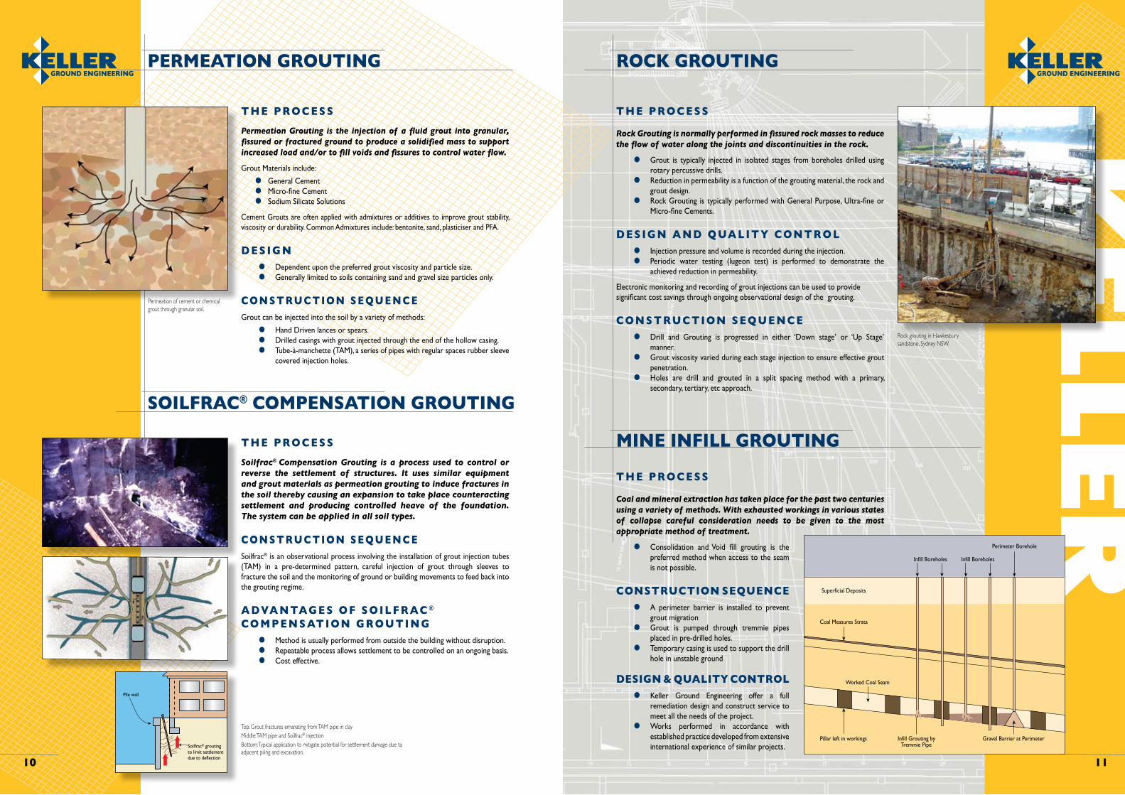
MINE INFILL GROUTING
T H E P R O C E S S
Coal and mineral extraction has taken place for the past two centuries using a variety of methods. With exhausted workings in various states of collapse careful consideration needs to be given to the most appropriate method of treatment.
• Consolidation andVoid fill grouting is thepreferred method when access to the seam is not possible.
CONSTRUCTION SEQUENCE
• A perimeter barrier is installed to prevent grout migration
• Grout is pumped through tremmie pipes placed in pre-drilled holes.
• Temporary casing is used to support the drill hole in unstable ground
DESIGN & QUALITY CONTROL
• Keller Ground Engineering offer a full remediation design and construct service to meet all the needs of the project.
• Works performed in accordance with established practice developed from extensive international experience of similar projects.
Permeation of cement or chemical grout through granular soil.
Rock grouting in Hawkesbury sandstone, Sydney NSW.
Superficial Deposits
Coal Measures Strata
Worked Coal Seam
Pillar left in workings Infill Grouting byTremmie Pipe
Gravel Barrier at Perimeter
Perimeter Borehole
Infill BoreholesInfill Boreholes
Soilfrac® groutingto limit settlementdue to deflection
Pile wall

12
Ke l l e r G ro u n d E n g i n e e ri n g P t y L t d
BRISBANEMELBOURNESYDNEYPERTH
Enquiries to:PO Box 7974, Baulkham Hills NSW 1755Level 1, 4 Burbank PlaceBaulkham Hills NSW 2153 Australiat: (02) 8866 1155f: (02) 8866 1151e: [email protected] w: www.kellerge.com.au