special torque tightening figures torque tightening figures introduction ... (engine speed sensor...
TRANSCRIPT

Chapter L
Special torque tightening figures
Contents
Contents and issue record sheet
1987188189 model years Special torque tightening figures
Sections RolBRoyce Bentley Silver .Silver Cwniche / Eight Mulsanne/ Turbo R Continental Spirit Spur Comiche II Mutsanne S
Issue record sheet The dates quoted below refer to the issue date of individual pages within this chapter.
Sections 1 LV 1 U l I I I ! 1 I i I Page No. I I I I I i
30 31 32 3 3 34 35 36 37 38 39 40 4 l 42 43 44 45 46 47 48 49 50 5 1 52 5 3 54 L.. l I I t I F I 1 l t 5/88 TSD 4737
L1 -3

Section L2
Special torque tightening figures
Introduction This seclior~ cnrltnirrs Ilm sl~ecial Inrquu tigl~lcnrr~g figures applicable lo tlr~s Workshop Manwl.
For standard torque tightening figures refer to Chapter P. in Workshop Manual TSD 4700.
Chapter B Ref.
1
Cnrnponents used during manufacture of the vehicle have dillarent thread formations (Metric. UNF. UNC, etc.). Therefore. wlten fitting nuts, boils, and setscrews it is impofiant to ensure that the correct type arrd size of thread formation is used.
Component
Air flow sensor plate - setscrew
Thermal time switch
kgf m IM ft
0.5-0.55 44-48 Ibf. in.
Primary system pressure regulator (large hexagon)
Oxygen sensor When fitting an oxygen sensor. always smear the threads with Never-seez assembly compound. Do not allow the assembly compound onto the slotted shield below the threaded portion
TSD 4737
L2-l

Chapter C Ref. Component Nrn ksf m lbf ft
Chapter D
Fuel pressure damper to fuel pump When tightening the component ensure that the pump outlet is held firmly with a spanner. otherwise the flexible pump mounts may be strained
Turbocharger assembly to exhaust manifold - stud 4 off
Wastegate assembly to exhaust manifold - stud 2 off
Turbocharger assembly to exhaust manifold - nut 4 off
Wastegate assembly to exhaust manifold - nut 2 off

Chapter F Ref. Component #m kgf m lM ft
2 Air pumpclutched pulley -nut
m . . . TSD 4737
L2-3
Chapter M
Workshop tools
Contents Sections Rolls-Royce Bentiey Silver Silver Carniche) Eight Mulsanne/ Turbo R Continental Spirit Spur Corniche II Mulsanne S
Contents-and issue record sheet M1 M l M1 M1 M l M1 ' M1
i987 /sm model years Workshop tools M2 M2 M2 M2 M2 M2 M2
TSD 4737
M1,- 1

Issue record sheet The dates quoted below refer to the issue dates of individual pages within this chapter.
Sections M1 M2 Page No. 1 f0/91 10E91 2 3 10191 - 4
B ~ ~ Q U P Page No. 1 2 3 4 5 6 7 8 9
7 0 11 12 13 14 7 5 .l 6 17 18 19 20 - -- 21 22 23 24
10B1 TSD 4737

Section M2
Workshop tools
RH .S090 Pliers
RH 9607 Adapter (for use with pressure tester)
RH 1221 0 K- Motronic ECU interrogator (for use on turbocharged cars without the on- board fault diagnosis capability)
RH 1221 1 Atlas Copco belt tension meter RH 9608 Mixture adjusting tool
RH 9609 Guide ring
RH 9612 Prossurr! tostar (6 bar gauge used on K-Jetronic)
RH 9873 Pressure tester (10 bar gauge used on K-Jetronic, KE2- Jetronic. and K - Motronicl
SPM7390/1 'Firtree' type nipple and nut
RH 9613 Fuel delivery quantity comparison tester
RH 9614 Injector test equipment
RH 9615 • 'Closed loop' system tester (Only use with RH 9979)
RH 9645 Hose and adapter (for use with pressure tester)
RH 9876 CO sample tapping adapter (for use on naturaliy aspirated cars fitted with catalytic converters)
RH 9881 Adapter {fuel distri butorl
RH 9893 Adapter (electrical connection to EHA)
RH 9928 Rernoval/f itting tool {fuel tanksender unit and in-tank filter)
RH 9960 Accessory kit (comprising fuel distributor adapters and AFS plate operating screw)
RH 9979 'Connection lead {Only use with RH 96151
RH 12207 Setting tool (engine speed sensor air gap)
l onr
RH 12495 Mityvac vaeuurn/pressure pump and gauge assembly
RH 13014 * 'Closcd loop' syslnm tcstcr {Only use with RH 130f5)
RH 13015 "Connection lead (Only use with RH f 301 41
Alternatives in sets (Use on cars with a K - Jetronic fuel injection system and a catalytic converterts). fitted in the exhaust system)
TSD 4737

Chapter N
Running changes
Contents
Contents and issue record sheet
No. 1 Thefitting of twosir pressure transducers
No. 2 1988Model yearchanges (Swissor Austrian specification]
No. 3 K-Matronic ECU imerrogatorRH 12210
No. 4 AtksCopco belt tension meter RH1221 1
Sections Rolls-Rayce Bentley Silver Silver Carniche/ EigM Mulsanne/ Turbo R Continental Spirit Spur Comiche It Mulsanns S

Issue record sheet The dates quoted below refer to the issue date of individual pages within this chapter.
1 I I l I I I I L -- 1 1 1/89 TSD 4737
Sections l R = I W? I U4 1 NB I I 1 1 l Page Mm I l
1 1189 5EB8 1189 1189 1 W9 2 1189 1189 3 1/89 4 5 6 7 8 9
1 0 11 I2 13 14 15 16 17 18 19 20 2 1 22 2 3 24 2 5 26 27 2 8 2 9 30 31 32 33 34 35 3 6 3 7 38 3 9 40 4 1 42 43 44
. 45 46 4 7 48 49 50 5 1 52 53 54
Section NZ
Running changes No 1 The fitting of two air pressure transducers
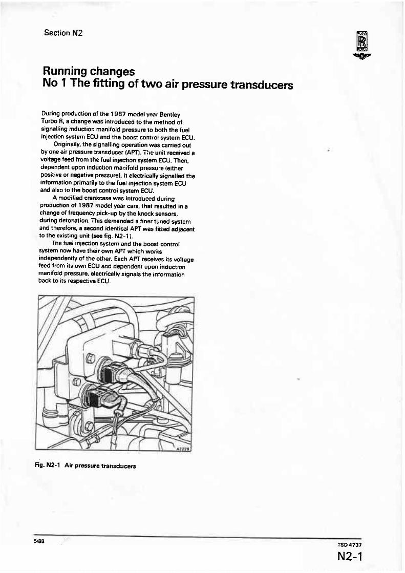
During production of the 1 987 modef year Bentley Turbo R, a change was introduced to the method of signalling induction manifold pressure to both the fuel injection system ECU and the boost contml system ECU.
Originally. the signalling operation was carried out by one air pressure transducer {Am. The unit received a voltage feed from the fuel injection system ECU. Then, dependent upon induction manifold pressure (either positive or negative pressure], it electrically signal14 the information primarily to the fuel injection system ECU and also to the boost control system ECU.
A modified crankcase was introduced during production of 1987 model year cars. that resulted in a change of frequency pick-up by the knock sensors, during detonation. This demanded a finer tuned system and therefore, a second identical APT was fitted adjacent to the existing unit (see fig. N2-1).
The fuel injection system and the boost control sfltem now have their own APT which works independently of the other. Each APT receives its voltage feed from its own ECU and dependent upon induction manifold pressure, electrically signals the information back to its respeciive ECU.
Fig. N2-1 Air pressure transducers

Section N3
Running changes No 2 1988 Model year changes
The information contained within this running change up-dates the manual for 1988 model year cars.
The main changes to the various build specifications affect cars produced to a Swiss ar Austrian specification. For the 1988 model year these cars are fitted with a catalytic converter and a power train very similar to that fined to cars produced to a North American specification. The only differences are that the Swiss and Austrian cars do not have an oxygen sensor warning lamp on the facia. They do however. have a new type of exhaust gas sample tapping (see fig. N3-1) fitted in front of the catalytic converter.
The other change that affects all 1988 modet year cars is that the model year identification Letter in the vehicle identification number IVlN) has changed. The tenth digit in the VIN of 1988 model year mrs is the letter J (e.g. +SCAZS02AGJCX2'1057*].
Fig. N3-l Exhaust gas sample take-off 1 Outside edge of vehicle 2 Tube end cap 3 Exhaust adapter 4 Exhaust gas flow into catalytic converter 5 Heat resistant flexible tube
TSD 4737
N3-1

Section N4
Running changes No 3 K-Motronic ECU interrogator RH 12210
1989 model year Bentley Turbo R motor cars are equipped with a Bosch K-Motronic engine management system.
The K-Motronic electronic control unit (ECUI provides a self diagnostic fault finding facility for the engine management system.
On cars fitted with full emission control systems including catalytic converters, this fault finding facility is interpreted as a blink code via the facia mounted CHECK ENGINE warning panel. Refer to Chapter B. Section R4 for full details.
On all other 1989 model year turbocharged cars, the K-Motronic ECU incorporates the self diagnostic capability but there is no 'on-board' facility for displaying the information. To carry out a fault finding check on these cars use test box RH 12210. This test box will interrogate the K-Motronic ECU and exhibit its findings as blink codes on the test box indicator lamp.
The procedure for using the interrogator is as follows. 1. Ensure that the usual workshop safety precautions are carried out. 2. Open the cover to reveal the main fuseboard. 3. Closely inspect the area below and behind the fuseboard (see fig. N4-1 l . Locate the two cables. one green~yellow, the other black, taped back into the loom. T hese two cables should be freed and positioned as shown in the illustration. Note If the ECU has not previously been interrogated
by this method it may be necessay to improve access to the loom. Disconnect the battery. Refer to TSD 4848 and release the fuseboard assembly from its mounting. Carefully move the fuseboard assembly into the car to provide the improved access. . If the ECU has been subjected to interrogation
by this method previously, the greenlyellow and the black cables will be readily accessible and Operations 4 to 7 inclusive'omitted.
4. Ensure that the two cables are insulated. 5. Connect the battery. 6. Carry out a thorough road test on the car. 7. Upon return. carry out the usual workshop safety precautions. Ensure that the ignition is switched off and withdraw fuse B5 from fuse panel F1 on the main fuseboard. 8. Connect the test box RH 12210 to the car as shown in figure M4-1. 9. Insert fuse B5 and note that the indicator lamp on the test box is illuminated. 10. Turn the ignition key to the RUN position. 11. De~ress the button on the test box for a minimum of four'seconds. 12. Release the button and monitor the biink code displayed on the test box indicator tamp.
Fig. N4-1 Boseh K-Motronic interrogator in position
The inilial period will be 2.5 seconds lamp on and 2.5 seconds lamp off. Afterwards, the fault code will be revealed (see fig. N4-21.
The fault code 4.4.3.1. is shown in the illustration. 13. Once a blinkcode has been initiated. it will keep repeating the information {with further initiation periods identifying blink code commencement), until the button on the test box is depressed for another four seconds period.
This procedure must be repeated until all stored blink codes have been extraaed from the K-Motronic ECU. 14. If there are no more fault codes stored, the condition is identified by the unique code 1.1.1.1. The test box indicator lamp onloff periods for this code are of 2.5 seconds duration. 15. To reset the ECU following fault extraction andlor rectification. isolate the vehicle battery for more than four seconds. Use the master switch located in the tuggage compartment, whenever possible. 16. If there are no faults stored in the ECU, the btink

LAMP ON
M P OFF
Example brink code 4.4.3.1.
Fig. N4-2 Bowh K-Motronic ECU fault codes
1
code 4.4.4.4. will register on the test box indicator The cable connectors must not be allowed to contact lamp. other components. '17. Upon completion of the tests, switch off the 20. Insert fuse BS. ignition, withdraw fuse B5 from fuse panel F1 on the main fuseboard, and remove the rest box connections. 18. Connect the cable to the fuseboard illumination lamp. 19. Insulate the greenlye1 tow and the black cables. Tape them back to the loom behind the fuseboard, ensuring that they are safe but accessible for future use.
lhe impamnet! of correctly insulating and stowing these two cables cannot be over emphasized.
Biinkcode Fnukdesctiption System method d recognition Limp hornefseility 4.4.4.4. Nofaulisstored
4.3.1.2. Engine reference sensor and1 Synchronization lost Dependent upon ECU data update or its connection to the ECU prior to theengine reference defective sensor failure
2.3.1.2. Coolant temperature sensor Coolant temperature Lessthan K-MotronicECU providesEHAwith output outside operating 46'C (-50.8'F) or rlorethan rnA compensation equivalent to range 186% (366.80F) BO"C (176°F) coolant temperature
for all operational modes other thansfaning which is setto l, 2rc ( W F )
2.2.3.2. Incorrect air flow signal Volumetric airflow rats Ignition and fuelling switched to outside pressure upper and full load map lower lirnirs
2.1.2-1. Idle switch fault. Idle Idleswitch closed. Air sensor Ignition andfuelling switched to control maps not recognised platevolrage ratiogreaterthsn part load map
0.56for morethan 0.3 seconds 2.1.2.3. Full loadswitch fault. Full loadswitch closed but ECU ignition andfuelling switched to
Full load control maps not recognises part loadengine part load map recognised operation formore then 0.3
seconds 2.1.1.3. Engine speed sensor andtor Ignition switched on,valumetric None
connection tothe ECU airflow ratemorethan 9rn3/hr defective. Air sensor plate but no engine spwedsignal mechanism or fuel distributor plunger stuck
4.4.3.1. Idle slaeedaeluator connecting End stage within K-MotmnicECU Limp homeengine idlespeed of plug open or short circuit 900 rwlmin. Normal engine
operalion except idle mode 1.1.1.1. Nombrefaultsstoredin ECU Blinklamp onloff periodsfor
memory thiscode are of 2.5 seconds duration
- - e

Section N5
Running Changes No 4 Atlas Copco belt tension meter RH 1221 1
When checking the tension of the air pump driving belt, use the Atlas Copco tension meter RH 12211.
The tension meter consists of two main components, the clamping unit. incorporating 8
hydraulic cylinder and a trigger operated read-out unit (see fig. N5-1).
The tension meter should befitted closeto the mid- point of the drive belt span, as shown in figure N5-2. The procedure for using the tension meter is as follows. 1. Ensure that the usual workshop safety precautions are carried out. 2. Ensure that the engine is cold. A warm engine will return a higher belt tension reading. 3. Inspect the drive belt for either cracks or glazing. Renew the belt if necessary. 4. Examine the back of the drive belt around the mid- point of the span. If any irregularities are found where the clamping unit is to be fitted, rotate the engine until the area of the belt is acceptable. 5. Belt tension readings should always be taken over one belt only. Therefore. the belt blocker should be fitted prior to using the gauge for the first time arid thereafter remain in position in theclamping unit (see fig. N5-1). 6. Open the jaws of the clamping unit by applying pressure at the two points indicated by the arrows in figure N5-l. 7. Position the clamping unit with the jawsopen, onto the mid-point of the belt span as shown in figure NS-2. Release the clamping unit. 8. Initially, adjtrst the small Allen screw situated on the top of the clamping unit until the clamping unit wiH onty just dide along the belt. This operation need only be carried out if the clamping unit is a poor fit on the belt. 9. Squeeze the trigger of the read-out unit. The reading displayed on the gauge when the red lamp illuminates is the belt tension.
Repeat this procedure until the clamping unit has settled on the belt and the readings becomeconsistent. Note this figure. 10. Remove the clamping unit from the belt. 1'1. Rotate the engine. 12. Repeat ~ ~ e r a r i o n s 6 to 9 inclusive. The average of the two noted readings is the drive belt tension.
If the two readings vary by more than 45 N (10 Ibf), take a third reading by again removing the clamping unit, rotating the engine, and repeating Operations 6 to 9 inclusive- Discard the exceptional value and then average the two remaining readings. 13. Do not adjust the drive belt unless the tension has fallen below the minimum acceptable tension of 200 N (40 Ibf). 14. i f necessary, adjust the belt tension as described in Chapter F. of this Workshop Manual. The air pump
Fig. N5-1 Clamping unit A Bett btoeker
Fig. N5-2 Belt tension meter in position
drive belt should be tensioned to a figure of between 250 N and 300 N fS5 Ibf and 65 lbfl. '15. When adjusting the tension of the drive belt, the following points should be noted. a) the belt should be cold. b) rotate the engine and check the belt tension several times until a consistent reading is obtained. c) the pivot fixings should not be loosened by more than is necessary to allow the belt to be tensioned.

d] the belt tensioning figures quoted in Operation f 4, . apply equally to replacement or existing drive belts.
e) if a new belt has been fitted andwnsionsd, the belt tension must be checked afterthe engine has run for 15 minutes.