special-purpose proximity sensor e2ca
TRANSCRIPT
69
E2CAE2CA
Sensor type Shielded
3 m (9.8 ft) cable E2CA-X1R5A E2CA-X2A E2CA-X5A E2CA-X10A
5 m (16.4 ft) cable E2CA-X1R5A-5M E2CA-X2A-5M E2CA-X5A-5M E2CA-X10A-5M
Size M8 M12 M18 M30
Nominal sensing 0.3 to 1.5 mm 0.4 to 2.0 mm 1 to 5 mm 2 to 10 mmdistance (0.01 to 0.06 in) (0.02 to 0.08 in) (0.04 to 0.20 in) (0.08 to 0.39 in)
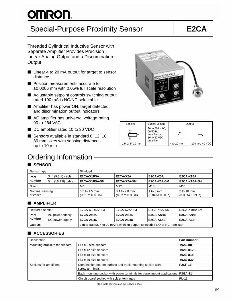
Threaded Cylindrical Inductive Sensor withSeparate Amplifier Provides PrecisionLinear Analog Output and a DiscriminationOutput
Linear 4 to 20 mA output for target to sensordistance
Position measurements accurate to±0.0006 mm with 0.05% full scale resolution
Adjustable setpoint controls switching outputrated 100 mA is NO/NC selectable
Amplifier has power ON, target detected,and discrimination output indicators
AC amplifier has universal voltage rating90 to 264 VAC
DC amplifier rated 10 to 30 VDC
Sensors available in standard 8, 12, 18,30 mm sizes with sensing distancesup to 10 mm
Ordering Information SENSOR
Required sensor E2CA-X1R5A/-5M E2CA-X2A/-5M E2CA-X5A/-5M E2CA-X10A/-5M
AC power supply E2CA-AN4C E2CA-AN4D E2CA-AN4E E2CA-AN4F
DC power supply E2CA-AL4C E2CA-AL4D E2CA-AL4E E2CA-AL4F
Outputs Linear output, 4 to 20 mA; Switching output, selectable NO or NC transistor
AMPLIFIER
Special-Purpose Proximity Sensor E2CA
Partnumber
Partnumber
Sensing Supply voltage Output
90 to 264 VAC,50/60 Hzamplifier or10 to 30 VDCamplifier
1.5, 2, 5, 10 mm 4 to 20 mA 100 mA, 40 VDC
Description Part number
Mounting brackets for sensors Fits M8 size sensors Y92E-B8
Fits M12 size sensors Y92E-B12
Fits M18 size sensors Y92E-B18
Fits M30 size sensors Y92E-B30
Sockets for amplifiers Combination bottom surface and track mounting socket with P2CF-11screw terminals
Back mounting socket with screw terminals for panel mount applications P3GA-11
Circuit board socket with solder terminals PL-11
ACCESSORIES
(This table continues on the following page.)

E2CAE2CA
70
Part number E2CA-X1R5A/-5M E2CA-X2A/-5M E2CA-X5A/-5M E2CA-X10A/-5M
Sensor type Inductive
Body Size M8 M12 M18 M30
Type Shielded
Required amplifier E2CA-AL4C or E2CA-AL4D or E2CA-AL4E or E2CA-AL4F orE2CA-AN4C E2CA-AN4D E2CA-AN4E E2CA-AN4F
Detectable object type Metallic objects
Effective maximum 1.5 mm (0.06 in) 2 mm (0.08 in) 5 mm (0.20 in) 10 mm (0.39 in)sensing distance(with standard target)
Usable sensing range 0.3 to 1.5 mm 0.4 to 2.0 mm 1 to 5 mm 2 to 10 mm(with standard target) (0.01 to 0.06 in) (0.02 to 0.08 in) (0.04 to 0.20 in) (0.08 to 0.39 in)
Standard target size 8 x 8 x 1 mm 12 x 12 x 1 mm 18 x 18 x 1 mm 30 x 30 x 1 mm(mild steel, L x W x H) (0.32 x 0.32 x 0.04 in) (0.47 x 0.47 x 0.04 in) (0.71 x 0.71 x 0.04 in) (1.18 x 1.18 x 0.04 in)
Response frequency 10 kHz 5 kHz 3 kHz
Indicators Not provided
Materials Housing Nickel-plated brass
Sensing face Plastic, acrylonitoryl butadiene styrene
Cable sheath Plastic, polyethylene
Mounting Two lock washers and Two lock washers and Two lock washers and Two lock washers andM8 nuts included. M12 nuts included. M18 nuts included. M30 nuts included.Bracket Y92E-B8 Bracket Y92E-B12 Bracket Y92E-B18 Bracket Y92E-B30optional. optional. optional. optional.
Connections Prewired 2-conductor shielded cable: 3 m (9.8 ft) length (E2CA-X A)5 m (16.4 ft) length (E2CA-X A-5M)
Weight with cable 40 g (1.4 oz.) 60 g (2.1 oz.) 140 g (5.0 oz.) 160 g (5.7 oz.)
UL —
NEMA 1, 4, 6, 12, 13
IEC 144 IP67
Approvals UL —
CSA —
Ambient operating -25° to 70°C (-13° to 158° F) -10° to 55°Ctemperature (14° to 131°F)
Vibration 10 to 55 Hz, 1.5 mm (0.06 in) double amplitude 10 to 25 Hz, 2 mm (0.08 in)double amplitude
Shock Approx. 50 G Approx. 10 G
Description Part number
Panel mounting adapter for amplifier Y92F-30
Protective covers for amplifier Hard plastic cover protects amplifiers from dust, dirt and water drip Y92A-48
Soft plastic cover protects amplifier from dust, dirt and water drip Y92A-48D
Mounting track DIN rail, 50 cm (1.64 ft) length PFP-50N
DIN rail, 1 m (3.28 ft) length PFP-100N
End plate PFP-M
Spacer PFP-S
Specifications
REPLACEMENT PARTS
Description Part number
Fits M8 size sensors (supplied with each sensor) M8-MHWS
Fits M12 size sensors (supplied with each sensor) M12-MHWS
Fits M18 size sensors (supplied with each sensor) M18-MHWS
Fits M30 size sensors (supplied with each sensor) M30-MHWS
SENSOR
Specifications Table — continued from previous page
Mounting hardwareincludes onepair of metalnuts and washers
Enclosureratings

71
E2CAE2CA
Part number E2CA-A 4C E2CA-A 4D E2CA-A 4E E2CA-A 4F
AC types 90 to 264 VAC, 50/60 Hz (E2CA-AN4 )
DC types 10 to 30 VDC (E2CA-AL4 )
AC types 60 mA max. (E2CA-AN4 )
DC types 70 mA max. (E2CA-AL4 )
Required sensor E2CA-X1R5A E2CA-X2A E2CA-X5A E2CA-X10A
Output range 4 to 20 mA
Resolution 0.05% to full scale
Linearity ± 2.0% of full scale ± 1.5% of full scale ± 2.0% of full scale
Response frequency 10 kHz 5 kHz 3 kHz
Adjustment 4 mA Adjustment to 4 mA at 20% of effective maximum detecting distance
20 mA Adjustment to 20 mA at effective maximum detecting distance
Operation mode NO or NC, switch selectable
Detecting distance Adjustable (within sensor’s “Usable Detecting Range”)sensitivity
Differential travel Fixed, 1 to 5% of detecting distance
Type Transistor, SPST
Max. load 100 mA, 40 VDC
Max. on-state 2 VDCvoltage drop
Response frequency 3 kHz 1.5 kHz 1 kHz
Switching output Not providedshort-circuit
DC power supply Providedreverse polarity
Weld-field immunity Not provided
RFI immunity Not provided
Indicators Power ON (POWER), Linear Range (SPAN), and Switching Output ON (OPER)
Materials Housing Plastic
Mounting Requires P2CF-11, P3GA-11 or PL11 sockets (not included); order separately fromAccessories.Adapter Y92F-30 for panel mounting the amplifier (optional); order separately fromAccessories.
Connections Plated steel screw terminals (P2CF-11 and P3GA-11 sockets); Solder terminals (PL11 socket)
AC types 250 g (8.8 oz.)
DC types 120 g (4.2 oz.)
UL —
NEMA 1
IEC 144 IP40
Approvals UL —
CSA —
Ambient operating temperature –10° to 55°C (–14° to 131°F)
Vibration 10 to 25 Hz, 2 mm (0.08 in) double amplitude
Shock Approx. 10 G
AMPLIFIER
Linearoutputcharacteristics
Currentconsumption
Switchingoutputcharacteristics
Supplyvoltage
Controloutput
Circuitprotection
Weight withoutsocket
Enclosureratings

E2CAE2CA
72
Classification Function
Linear output An analog 4 to 20 mA output signal proportional to the distance from the target to the face of the sensorwithin the range of the 4 mA linear setpoint to the 20 mA setpoint.
Switching output A 100 mA, 40 VDC rated transistor output (separate power source required) adjustable within the range of the4 mA linear setpoint and 20 mA linear setpoint.
Power ON Red LED illuminated when amplifier is connected to power source and energized.
Operation Red LED illuminated when the target is present within the range from the minimum sensing distance to thetarget setpoint distance.
Span Green LED illuminated when the target is present within the range of the 4 mA linear setpoint and the 20 mAlinear setpoint.
Cable length selector Set to the length of cable (3 or 5 meters) supplied on the sensor head.switch
4 mA linear adjustment Used to set the analog output at 4 mA when the target is at 20% of the rated sensing distance.Adjustment method 1.
20 mA linear adjustment Used to set the analog output at 20 mA when the target is at 100% of the rated sensing distance.Adjustment method 1.
Sensitivity Used to set the target distance that turns on the switching output.
Mode selector switch Determines the logic of the switching output circuit. In the NO position, the target turns on when the target ispresent between the minimum sensing distance and the target setpoint distance. In the NC position, theswitching output turns on when the target is beyond the target setpoint distance.
OPER. indicator (Red LED)Illuminates when the target ispresent within the range fromthe minimum sensing distanceto the target setpoint distance
SPAN indicator (Green LED)Indicates the linear area of the output current
Linear output current adjustment (20 mA)
Linear output current adjustment (4 mA)
POWER indicator (Red LED)Illuminates when energized
Mode selector switch
Selector switch for cablelength compensation
SENSITIVITY adjustmentAdjusts the target setpointdistance for switching output
FUNCTION — AMPLIFIER
AMPLIFIER
TIMING CHART100% rated distance
Target setpoint distance
20% rated distance
Distance oftarget
20 mA
4 mA
Linearoutput
SPAN indicator
Mode selector• NO position
• NC position
Switchingoutput
Operatorindicator
Switchingoutput
Operatorindicator
Nomenclature
Operation
OUTPUT
INDICATORS
ADJUSTMENTS

73
E2CAE2CA LINEAR OUTPUT ADJUSTMENTSChoose one of the two adjustment methods for setting theLINEARITY adjuster. Adjustment of the 4 mA and20 mA LINEARITY adjusters must be performed with thestandard target at positions of 20% and 100% of the rateddetecting distance away from the sensor.
Linearity Adjustment Method 1
1. Connect an ammeter across terminals 1 and 2. Theillustration shows the sensor connected to an amplifierthrough socket P2CF-11.
2. Place the standard target at 20% of the rated detectingdistance away from the sensor unit.
3. Turn the 4 mA LINEARITY adjuster slowly clockwise (toincrease the output current) or counterclockwise (todecrease the output current). Set the adjuster to a positionthat reads 4 mA output on the ammeter.
4. Place the standard target at the rated detecting distance.
5. Turn the 20 mA LINEARITY adjuster slowly clockwise (toincrease the output current) or counterclockwise (todecrease the output current). Set the adjuster to a positionthat reads 20 mA output on the ammeter.
6. To fine tune the adjustment accuracy of the output current,repeat the adjustment steps for 4 mA and 20 mALINEARITY adjusters.
Linearity Adjustment Method 2
1. Set the standard target at 20% of the rated detectingdistance away from the sensor.
2. Turn the 4 mA LINEARITY adjuster counterclockwise so thatthe SPAN indicator remains OFF. Then slowly turn theadjuster clockwise until the indicator illuminates. Stopturning the adjuster at the position where the SPANindicator illuminates.
3. Set the standard target at the rated detecting distance awayfrom the sensor.
4. Slowly turn the 20 mA LINEARITY adjuster clockwise untilthe SPAN indicator goes OFF. Then turn the adjustercounterclockwise until the indicator illuminates. Stop turningthe adjuster when the SPAN indicator illuminates.
SENSITIVITY ADJUSTMENTS
S
0.8
Place the standard target at the specified position. If the targetmoves in parallel with the surface of the sensor unit, make theadjustment after determining the position using the followingprocedure.
1. Adjust the linear output according to Adjustment Method 1or 2.
2. Calculate detecting distance X using the following formula:
X = S = setting distance
3. Adjust the distance between the sensor and the object tobe detected to distance X.
Slowly turn the SENSITIVITY adjuster clockwise (toward HIGH)and stop turning when the OPER. indicator illuminates. Movethe target to confirm that the OPER. indicator illuminates whenthe object to be detected is at the specified position and thatthe indicator goes OFF when the target is moved away fromthat position.
If the target moves in parallel with the surface of the sensorunit, place the sensor at distance S.
E2CAE2CA
74
The output transistor turns ON when thetarget is detected.
The output transistor turns ON when thetarget is not being detected.
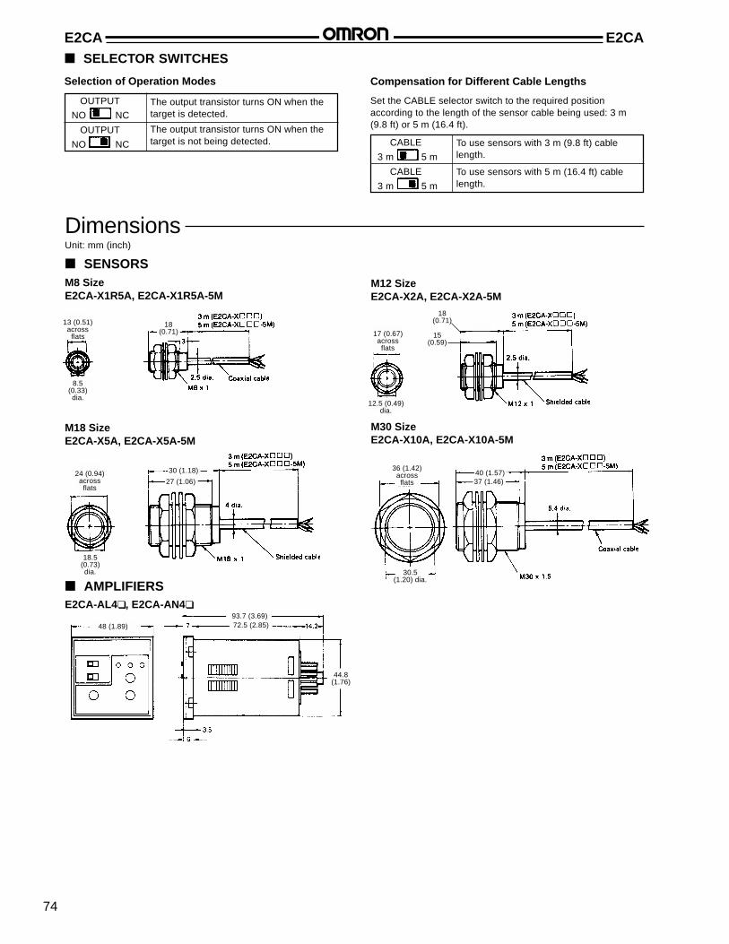
Dimensions
Selection of Operation Modes
SELECTOR SWITCHES
Compensation for Different Cable Lengths
OUTPUT
NO NC
OUTPUT
NO NC
Set the CABLE selector switch to the required positionaccording to the length of the sensor cable being used: 3 m(9.8 ft) or 5 m (16.4 ft).
To use sensors with 3 m (9.8 ft) cablelength.
To use sensors with 5 m (16.4 ft) cablelength.
CABLE
3 m 5 m
CABLE
3 m 5 m
Unit: mm (inch)
SENSORSM8 SizeE2CA-X1R5A, E2CA-X1R5A-5M
M12 SizeE2CA-X2A, E2CA-X2A-5M
M18 SizeE2CA-X5A, E2CA-X5A-5M
M30 SizeE2CA-X10A, E2CA-X10A-5M
AMPLIFIERSE2CA-AL4 , E2CA-AN4
13 (0.51)across
flats
8.5(0.33)dia.
18(0.71)
12.5 (0.49)dia.
17 (0.67)across
flats
24 (0.94)across
flats
30 (1.18)
18.5(0.73)dia.
27 (1.06)
36 (1.42)across
flats
30.5(1.20) dia.
40 (1.57)37 (1.46)
48 (1.89)
93.7 (3.69)72.5 (2.85)
44.8(1.76)
18(0.71)
15(0.59)

75
E2CAE2CA SOCKETS FOR AMPLIFIERSP2CF-11 Track-Mount Socket with Screw Terminals
Terminal Arrangement(top view)
Mounting Holes
P3GA-11 Back-Mounting Socket with Screw TerminalsTerminal Arrangement(bottom view)
PL11 Circuit Board Socket with Solder Terminals
Terminal Arrangement(bottom view)
Mounting Holes
MOUNTING TRACK AND ACCESSORIESPFP-100N/PFP-50N DIN Rail Track PFP-M End Plate PFP-S Spacer
Y92A-48, Y92A-48D OPTIONAL PROTECTIVE COVERS FOR AMPLIFIERSHard plastic cover Y92-48 and soft plastic cover Y92A-48Dsnap onto the front of the amplifier to protect it from dust, dirtand water drip. The Y92A-48 hard plastic cover projects 4 mmfrom the front of the amplifier. Y92A-48D soft plastic cover fitssnugly over the front.
70(2.76)max.
50 (1.97)max.
31(1.22) max.
35.4(1.39) 40 ±0.2
(1.57 ±0.008)
Note: The socket can be mounted on DINrail track or surface mounted usingtwo through holes.
45 (1.77)
26.6(1.05)
45(1.77)
51(2.01)max.
40(1.57)
3.5(0.14)
30(1.18)dia. 31 (1.22)
dia. hole40 ±0.3
(1.57 ±0.01)
35(1.38)max.
E2CAE2CA
76
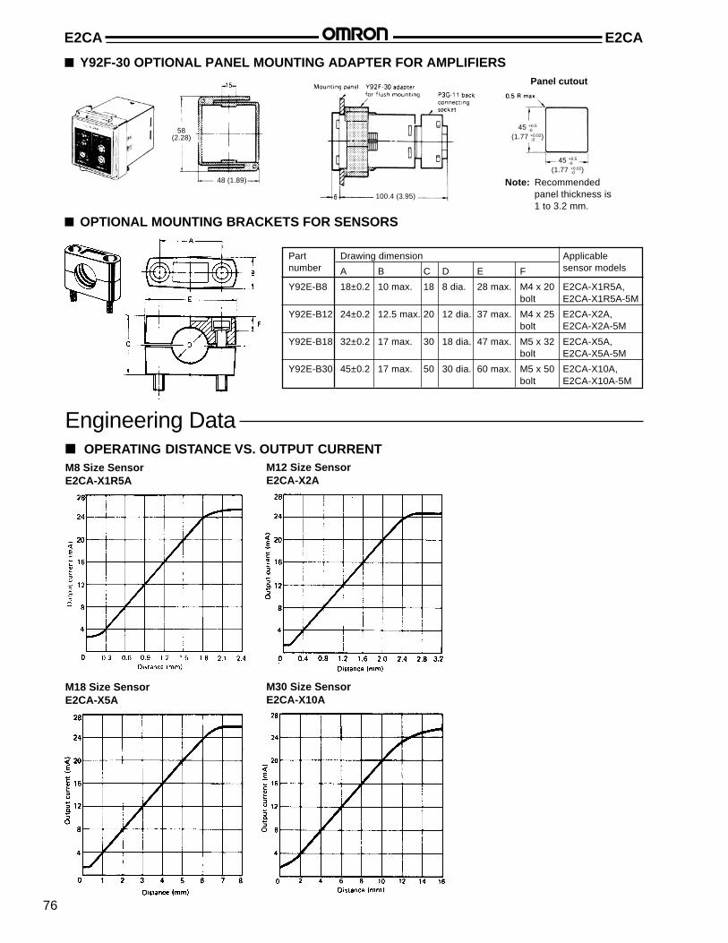
Drawing dimension
A B C D E F
Y92E-B8 18±0.2 10 max. 18 8 dia. 28 max. M4 x 20 E2CA-X1R5A,bolt E2CA-X1R5A-5M
Y92E-B12 24±0.2 12.5 max. 20 12 dia. 37 max. M4 x 25 E2CA-X2A,bolt E2CA-X2A-5M
Y92E-B18 32±0.2 17 max. 30 18 dia. 47 max. M5 x 32 E2CA-X5A,bolt E2CA-X5A-5M
Y92E-B30 45±0.2 17 max. 50 30 dia. 60 max. M5 x 50 E2CA-X10A,bolt E2CA-X10A-5M
OPTIONAL MOUNTING BRACKETS FOR SENSORS
Engineering Data OPERATING DISTANCE VS. OUTPUT CURRENTM8 Size SensorE2CA-X1R5A
M12 Size SensorE2CA-X2A
M18 Size SensorE2CA-X5A
M30 Size SensorE2CA-X10A
Partnumber
Applicablesensor models
Y92F-30 OPTIONAL PANEL MOUNTING ADAPTER FOR AMPLIFIERSPanel cutout
Note: Recommendedpanel thickness is1 to 3.2 mm.
58(2.28)
48 (1.89)
100.4 (3.95)
45 +0.5
(1.77 +0.02)-0
-0
45 +0.5
(1.77 +0.02)-0
-0

77
E2CAE2CA
DETECTING DISTANCE VS. LINEARITY(SQUARE AND RECTANGULAR OBJECTS)
M8 Size SensorE2CA-X1R5A
M12 Size SensorE2CA-X2A
M18 Size SensorE2CA-X5A
M30 Size SensorE2CA-X10A
DETECTING DISTANCE VS. LINEARITY (CYLINDRICAL OBJECTS)M8 Size SensorE2CA-X1R5A
M12 Size SensorE2CA-X2A
M18 Size SensorE2CA-X5A

E2CAE2CA
78
OUTPUT CIRCUIT DIAGRAM
Installation
CONNECTIONS BETWEEN SENSOR AND AMPLIFIER
CONNECTION OF LINEAR OUTPUT
Note: The illustration shows the linear output connected to a resistive load.
* Resistance R when E2CA-AL4 is used: 300 Ω max. at 24 V/150 Ω max. at 12 VResistance R when E2CA-AN4 is used: 300 Ω max.
Note: The illustrations show the terminal arrangement viewed from the rear of the socket that is coupled to the amplifier.
DC Amplifier and Sensor AC Amplifier and Sensor

79
E2CAE2CA CONNECTION OF SWITCHING OUTPUTA transistorized photocoupler output is used for the switching output of the E2CA-A 4 amplifier unit, which offers flexibility forswitching different loads and power supply polarity selection.
Solid-state load
Sink load (photocoupler) Voltage load (logic circuit)
E2CA-A 4
amplifiers
Type of Direct load drive:load Relay or solenoid
MOUNTING SENSORS
Effects of Surrounding Metals
Shielded E2CA proximity sensors may be mounted flush witha metallic panel. Be sure to provide a minimum distance asshown in the table to prevent the sensor from being affectedby metallic objects other than the target.
Drawingdimension
Sensor model
E2CA-X1R5A E2CA-X2A E2CA-X5A E2CA-X10A
mm inch mm inch mm inch mm inch
L 0 0 0 0 0 0 0 0
d (dia.) 8 0.32 12 0.47 18 0.71 30 1.18
D 0 0 0 0 0 0 0 0
m 4.5 0.18 6 0.24 15 0.59 30 1.18
Mutual Interference
To prevent mutual interference between two sensors, be sureto space the two sensors at a distance greater than thatshown in the table.
Drawingdimension
Sensor model
E2CA-X1R5A E2CA-X2A E2CA-X5A E2CA-X10A
mm inch mm inch mm inch mm inch
A 20 0.79 30 1.18 50 1.97 100 3.94
B 15 0.59 20 0.79 35 1.38 70 2.76
Do not exceed the maximum torque listed in the table.
Tightening Force
Sensor model Maximum torque
kg-cm in-lbs
E2CA-X1R5A 20 17
E2CA-X2A 60 52
E2CA-X5A 150 130
E2CA-X10A 400 346
MOUNTING AMPLIFIERS
Track-Mount Installation Using P2CF-11 Socket
The P2CF-11 socket has two hooks that secure the E2CAamplifier to the socket. Be sure to allow at least 20 mm (0.79in) clearance above and below the socket to gain access andto release the hooks for servicing and maintenance. TheP2CF-11 socket may also be used for surface mounting theamplifier using the two through holes.
d (dia.)
L
mD
E2CAE2CA
80
Panel-Mount Installation Using Y92F-30 Adapter and P3GA-11 Socket
Insert the E2CA amplifier through the panel cutout. Push theY92F-30 adapter from the rear of the amplifier as far forwardtoward the panel as possible. Then tighten the two retainingscrews. Wire the P3GA-11 socket, then push it onto the rearof the amplifier. To release the adapter, lift the tab at the rearof the adapter.
Several E2CA amplifiers may be panel mounted closetogether using Y92F-30 adapter as shown here. Whenmounting two or more amplifiers in a vertical line, arrange theadapters so that their molded tabs are positioned on the rightand left sides. When mounting two or more amplifiers in ahorizontal line, arrange the adapters so that their molded tabsare positioned on the top and bottom sides.
Panel Cutout for Side-by-Side Mounting of Two Amplifiers
OMRON ELECTRONICS LLC. OMRON CANADA, INC.One East Commerce Drive 885 Milner AvenueSchaumburg, IL 60173 Scarborough, Ontario M1B 5V81-800-55-OMRON 416-286-6465
Cat. No. GC MSEN4 04/01 Specifications subject to change without notice. Printed in the U.S.A.
NOTE: DIMENSIONS ARE SHOWN IN MILLIMETERS. To convert millimeters to inches divide by 25.4.
OMRON ON-LINEGlobal - http://www.omron.comUSA - http://www.omron.com/oeiCanada - http://www.omron.com/oci