spd application guide...january 2019 spd application guide according to iec 61643-12(2018) and hd...
TRANSCRIPT

January 2019
www.raycap.com
SPD APPLICATION GUIDE According to IEC 61643-12(2018) and HD 60364-5-53(2016) Igor Juricev;Application Engineer
2
1.Applicable standards 2.Origin of transient overvoltages 3.Lightning protection zones (LPZ) 4.Partial lightning current calculation 5.SPD classification 6.SPD selection 7.Proper installation of SPD 8.OCPD (over-current protective devices) for
SPD protection)

3
STANDARDS
EN/IEC 62305-1 Protection against lightning-Part 1:General principles EN/IEC 62305-2 Protection against lightning-Part 2: Risk managment EN /IEC62305-3 Protection against lightning-Part 3:Physical damage to structure and life hazard EN/IEC 62305-4Protection against lightnung-Part 4:Electrical and electronic systems within structures

4
STANDARDS
EN/IEC 61643-11:Ed 1.0Low-voltage surge protective devices- Part 11;Devices connected to low voltage power systems-Requirments and test methods EN/IEC 61643-12 Low –voltage surge protective devices-Part 12 Surge protective devices connected to low voltage power systems-Selection and application principles

5
STANDARDS
EN/IEC 61643-21Low voltage surge protective devices-Part 21: Surge protective devices connected to telecommunications and signalling networks-Performance requirments and testing methods EN/IEC 61643-22,Low voltage surge protective devices-Part 22: Surge protective devices connected to telecommunications and signalling networks-Selection and application principles
6
STANDARDS
EN/IEC 61643-31 Ed1:Low voltage surge protective devices-Part 31:Requirments and test methods for SPDs for photovoltaic installations EN/IEC 61643-32/Ed1:Low voltage surge protective devices-Part 32:Surge protective devices for specific use including d.c.-Selection and application principles for SPDs connected to photovoltaic installations
7
STANDARDS
EN/IEC 60364-4-44 Electrical installations of buildings-Part 4-44 Protection for safety-Protection against voltage disturbances and electromagnetic disturbances-Clause 443:Protection against overvoltages of atmospheric origin or due to switching EN-HD/IEC 60364-5-53 Low voltage electrical installations-Part 5-53:Selection and erection of electrical equipment-Isolation,switching and control-Clause 534:Devices for protection against overvoltages
8
ORIGIN OF TRANSIENT OVERVOLTAGES
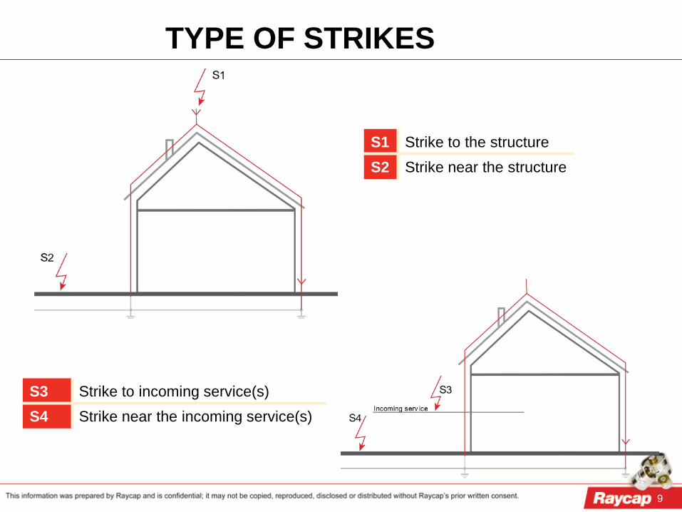
1. direct strikes (S1) to the external lightning protection system (LPS) of the building or lightning flashes near (S2) to the buildings
2. direct strikes (S3) and lightning induced currents (S4) distributed into the electrical network
3. overvoltages created by the distribution network, e.g., those due to switching operations
9
TYPE OF STRIKES
S3 Strike to incoming service(s) S4 Strike near the incoming service(s)
S1 Strike to the structure S2 Strike near the structure

10
Higher values Lower values 99 % < 125 kA 99 % > 5 kA 98 % < 102 kA 97 % > 7 kA 95 % < 73 kA 85 % > 11.9 kA
ORIGIN OF TRANSIENT OVERVOLTAGES

11
LPZ 0A Direct strikes, full lightning current, full magnetic field LPZ 0B No direct strikes, partial lightning or induced current, full magnetic field LPZ 1 No direct strikes, partial lightning or induced current, damped magnetic field LPZ 2 No direct strikes, induced current, further damped magnetic field
LIGHTNING PROTECTION ZONES (LPZ)
12
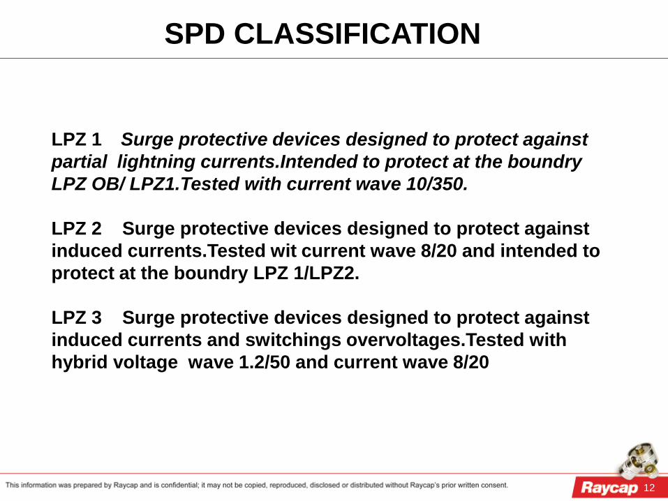
SPD CLASSIFICATION
LPZ 1 Surge protective devices designed to protect against partial lightning currents.Intended to protect at the boundry LPZ OB/ LPZ1.Tested with current wave 10/350. LPZ 2 Surge protective devices designed to protect against induced currents.Tested wit current wave 8/20 and intended to protect at the boundry LPZ 1/LPZ2. LPZ 3 Surge protective devices designed to protect against induced currents and switchings overvoltages.Tested with hybrid voltage wave 1.2/50 and current wave 8/20

13
LIGHTNING PROTECTION ZONES (LPZ)

14
SURGE CURRENT VALUES (EXTRACT FROM IEC 62305-1)
LPL FLASH TO STRUCTURE FLASH TO STRUCTURE
DIRECT AND INDIRECT FLASHES TO THE SERVICE
S1 (10/350) S1 (8/20)
S2 (8/20) S3 (10/350) S4 (8/20)
1phase 3phase Inductive coupling
Induced current
1phase 3phase Inductive coupling
I 50 kA 25 kA 10 kA 0,2 kA 20 kA 10 kA 5 kA
II 35 kA 17,5 kA 7,5 kA 0,15 kA 15 kA 7,5 kA 3,75 kA
III / IV 25 kA 12,5 kA 5 kA 0,1 kA 10 kA 5 kA 2,5 kA
Values per conductor

15
PARTIAL LIGHTNING CURRENT CALCULATION
15

16 This information was prepared by Raycap and is confidential; it may not be copied, reproduced, disclosed or distributed without prior written consent from Raycap.
SPD CLASSIFICATION
LPZ zones
Test class of SPD in acc. to IEC 61643-11
Category of SPD in acc. to IEC 61643-21
0/1 Test class 1 D1 1/2 Test class 2 C2 2/3 Test class 3 C1
SPD T 2 Zone 1/2
SPD T 3 Zone
2/3 PD
SPD T 1 Zone 0/1
UIn 1 4 kV
UIn 2 2.5 kV
UIn 3 1.5 kV
UP1 UP2 UP3

17 This information was prepared by Raycap and is confidential; it may not be copied, reproduced, disclosed or distributed without prior written consent from Raycap.
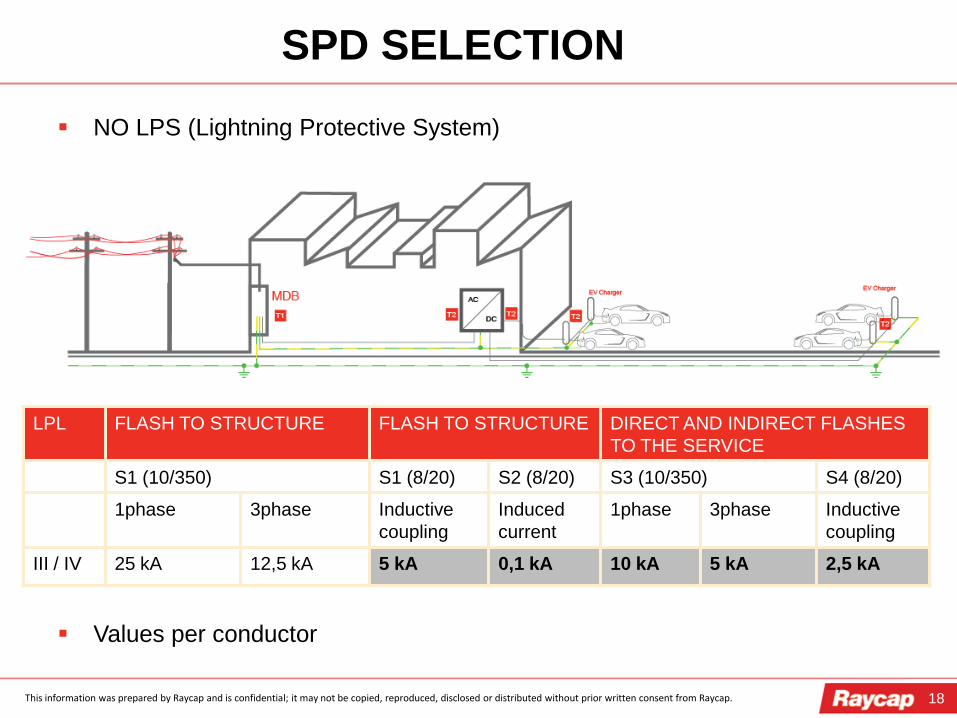
SPD SELECTION
NO LPS (Lightning Protective System)
LPL FLASH TO STRUCTURE FLASH TO STRUCTURE DIRECT AND INDIRECT FLASHES TO THE SERVICE
S1 (10/350) S1 (8/20) S2 (8/20) S3 (10/350) S4 (8/20)
1phase 3phase Inductive coupling
Induced current
1phase 3phase Inductive coupling
III / IV 25 kA 12,5 kA 5 kA 0,1 kA 10 kA 5 kA 2,5 kA
Values are per conductor
18 This information was prepared by Raycap and is confidential; it may not be copied, reproduced, disclosed or distributed without prior written consent from Raycap.
SPD SELECTION
NO LPS (Lightning Protective System)
Values per conductor
LPL FLASH TO STRUCTURE FLASH TO STRUCTURE DIRECT AND INDIRECT FLASHES TO THE SERVICE
S1 (10/350) S1 (8/20) S2 (8/20) S3 (10/350) S4 (8/20)
1phase 3phase Inductive coupling
Induced current
1phase 3phase Inductive coupling
III / IV 25 kA 12,5 kA 5 kA 0,1 kA 10 kA 5 kA 2,5 kA
19 This information was prepared by Raycap and is confidential; it may not be copied, reproduced, disclosed or distributed without prior written consent from Raycap.
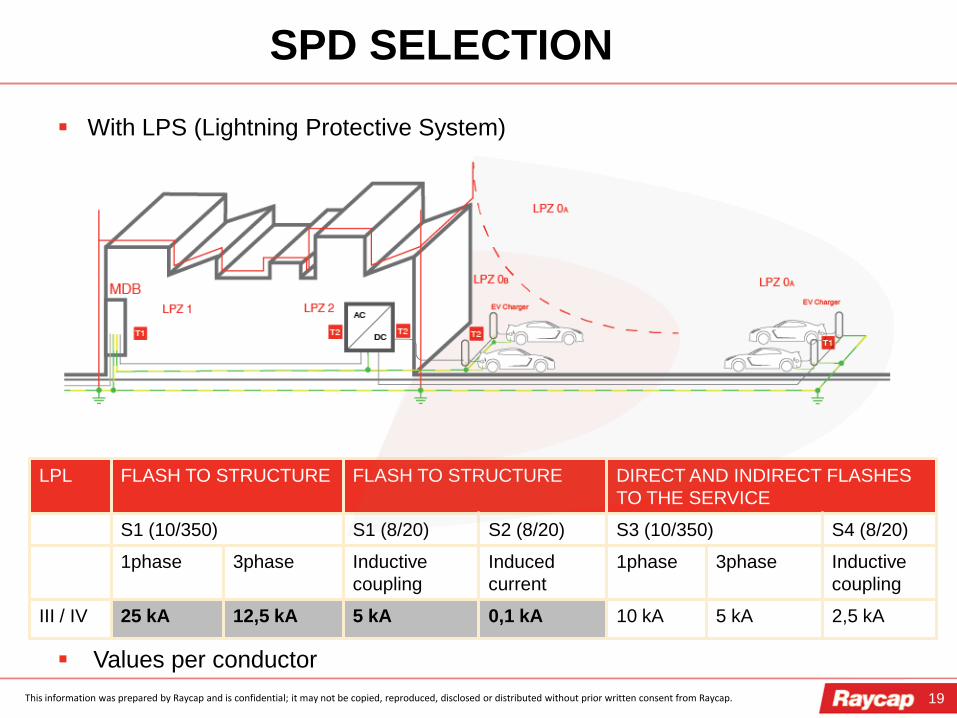
SPD SELECTION
LPL FLASH TO STRUCTURE FLASH TO STRUCTURE DIRECT AND INDIRECT FLASHES TO THE SERVICE
S1 (10/350) S1 (8/20) S2 (8/20) S3 (10/350) S4 (8/20)
1phase 3phase Inductive coupling
Induced current
1phase 3phase Inductive coupling
III / IV 25 kA 12,5 kA 5 kA 0,1 kA 10 kA 5 kA 2,5 kA
With LPS (Lightning Protective System)
Values per conductor
20 This information was prepared by Raycap and is confidential; it may not be copied, reproduced, disclosed or distributed without prior written consent from Raycap.
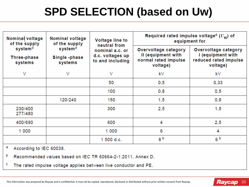
SPD SELECTION (based on Uw)
21 This information was prepared by Raycap and is confidential; it may not be copied, reproduced, disclosed or distributed without prior written consent from Raycap.
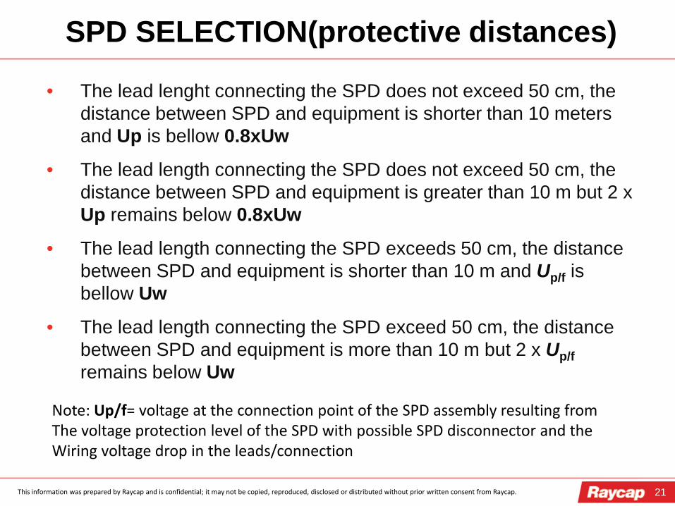
SPD SELECTION(protective distances)
• The lead lenght connecting the SPD does not exceed 50 cm, the distance between SPD and equipment is shorter than 10 meters and Up is bellow 0.8xUw
• The lead length connecting the SPD does not exceed 50 cm, the distance between SPD and equipment is greater than 10 m but 2 x Up remains below 0.8xUw
• The lead length connecting the SPD exceeds 50 cm, the distance between SPD and equipment is shorter than 10 m and Up/f is bellow Uw
• The lead length connecting the SPD exceed 50 cm, the distance between SPD and equipment is more than 10 m but 2 x Up/f remains below Uw
Note: Up/f= voltage at the connection point of the SPD assembly resulting from The voltage protection level of the SPD with possible SPD disconnector and the Wiring voltage drop in the leads/connection
22 This information was prepared by Raycap and is confidential; it may not be copied, reproduced, disclosed or distributed without prior written consent from Raycap.
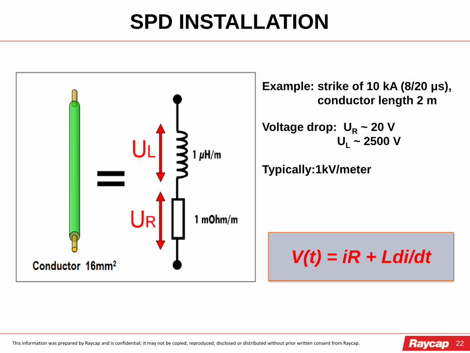
SPD INSTALLATION
Example: strike of 10 kA (8/20 μs), conductor length 2 m Voltage drop: UR ~ 20 V UL ~ 2500 V Typically:1kV/meter
V(t) = iR + Ldi/dt
23 This information was prepared by Raycap and is confidential; it may not be copied, reproduced, disclosed or distributed without prior written consent from Raycap.
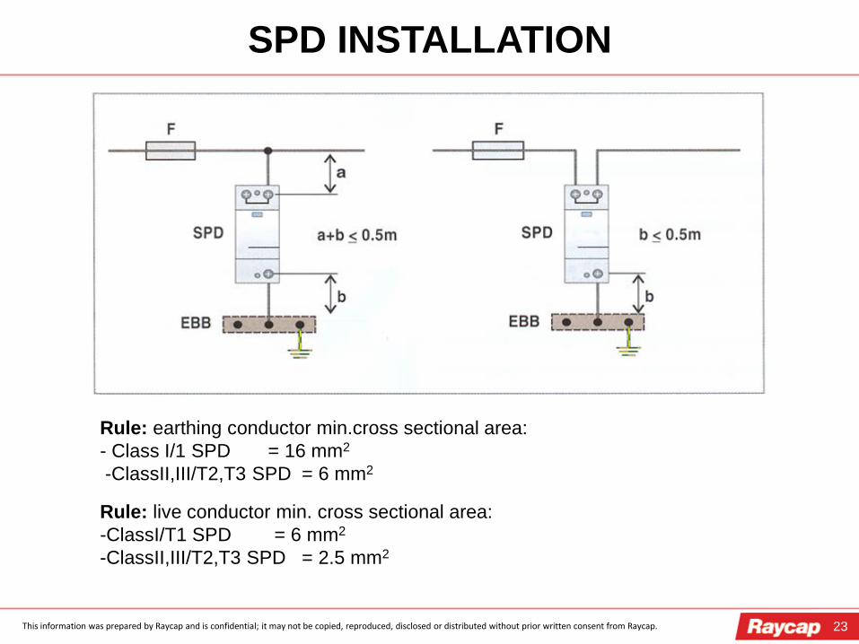
SPD INSTALLATION
Rule: earthing conductor min.cross sectional area: - Class I/1 SPD = 16 mm2
-ClassII,III/T2,T3 SPD = 6 mm2
Rule: live conductor min. cross sectional area: -ClassI/T1 SPD = 6 mm2
-ClassII,III/T2,T3 SPD = 2.5 mm2

24 This information was prepared by Raycap and is confidential; it may not be copied, reproduced, disclosed or distributed without prior written consent from Raycap.
SPD INSTALLATION (CT1)
25 This information was prepared by Raycap and is confidential; it may not be copied, reproduced, disclosed or distributed without prior written consent from Raycap.
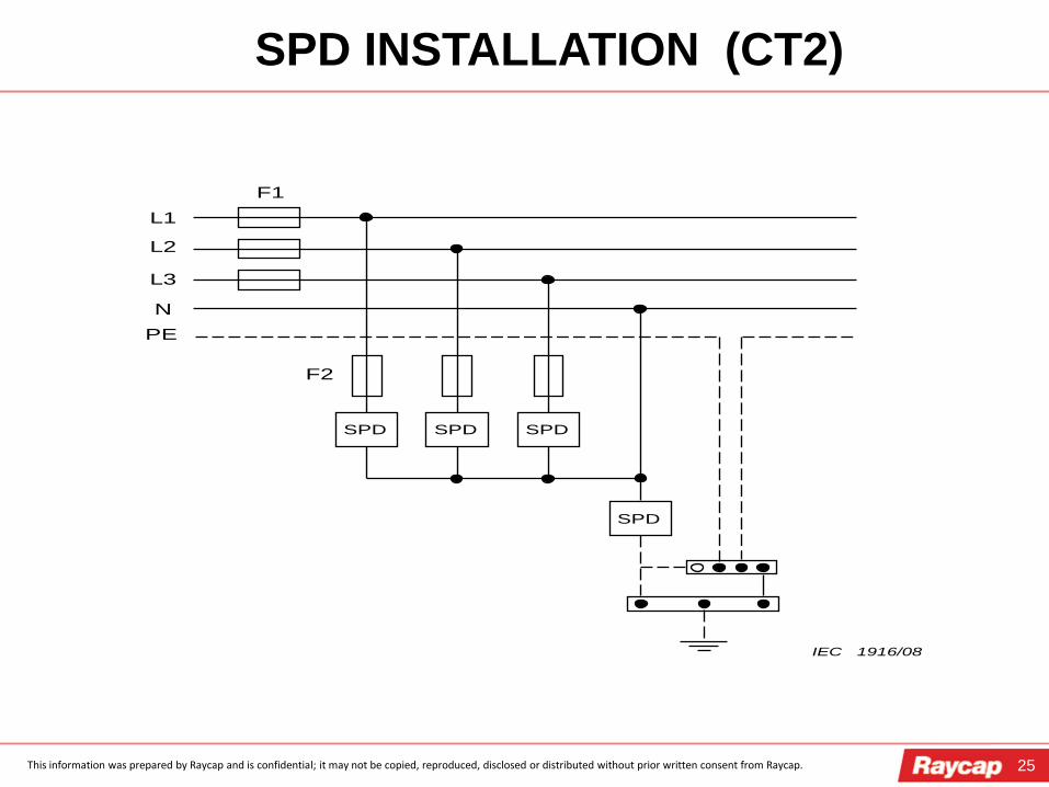
SPD INSTALLATION (CT2)
L1
L2
L3
N
F1
SPD
F2
PE
SPD SPD SPD
IEC 1916/08
26 This information was prepared by Raycap and is confidential; it may not be copied, reproduced, disclosed or distributed without prior written consent from Raycap.
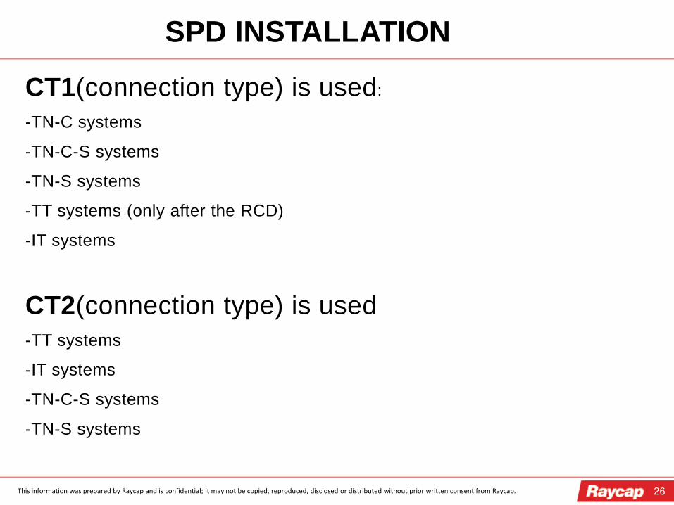
SPD INSTALLATION
CT1(connection type) is used:
-TN-C systems
-TN-C-S systems
-TN-S systems
-TT systems (only after the RCD)
-IT systems
CT2(connection type) is used -TT systems
-IT systems
-TN-C-S systems
-TN-S systems
27
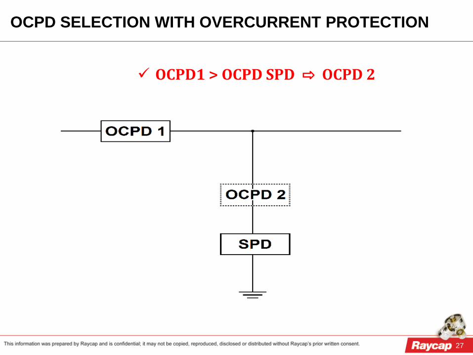
OCPD1 > OCPD SPD ⇨ OCPD 2
OCPD SELECTION WITH OVERCURRENT PROTECTION
28
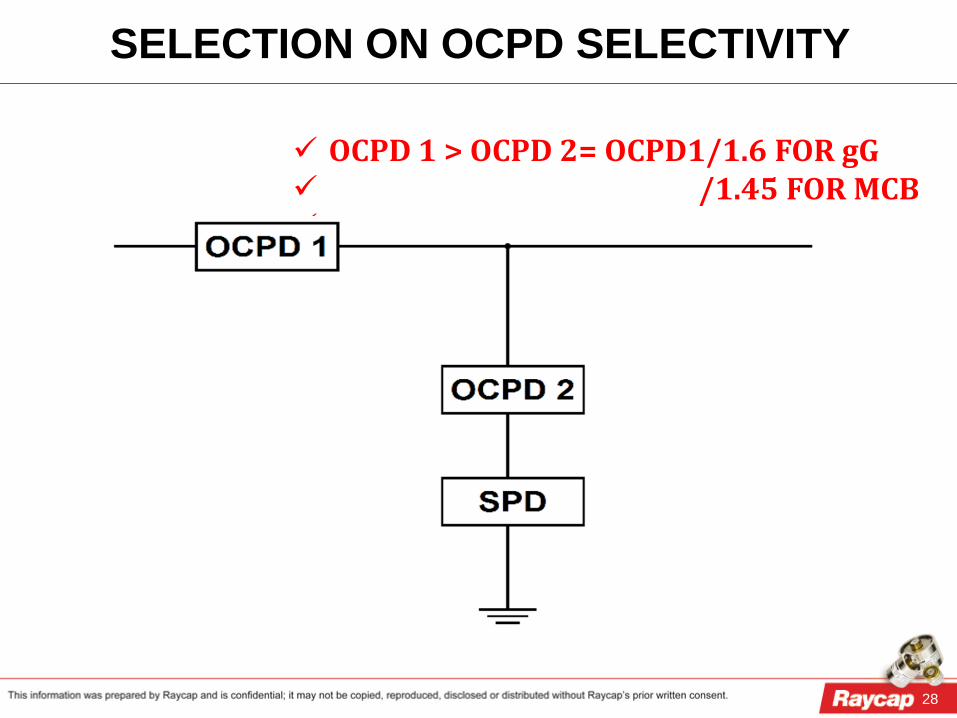
OCPD 1 > OCPD 2= OCPD1/1.6 FOR gG /1.45 FOR MCB
SELECTION ON OCPD SELECTIVITY

29
ISCCR > ISCCR SPD ⇨ OCPD 2
0CPD SELECTION ON ISCCR
30
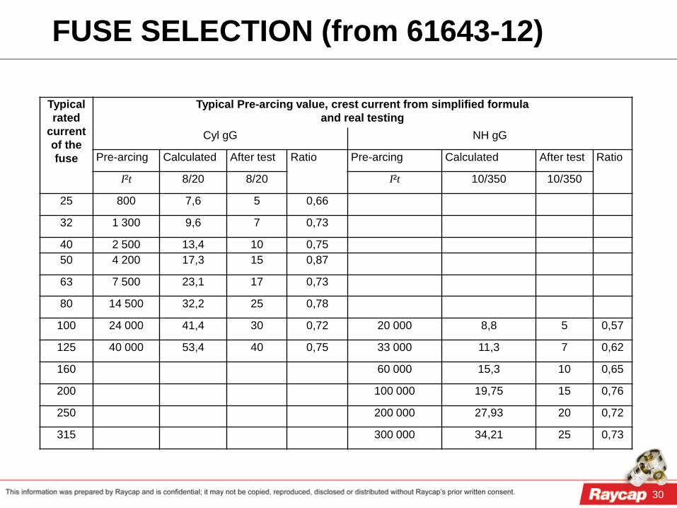
Typical rated
current of the fuse
Typical Pre-arcing value, crest current from simplified formula and real testing
Cyl gG NH gG
Pre-arcing Calculated After test Ratio Pre-arcing Calculated After test Ratio
I²t 8/20 8/20 I²t 10/350 10/350
25 800 7,6 5 0,66
32 1 300 9,6 7 0,73
40 2 500 13,4 10 0,75
50 4 200 17,3 15 0,87
63 7 500 23,1 17 0,73
80 14 500 32,2 25 0,78
100 24 000 41,4 30 0,72 20 000 8,8 5 0,57
125 40 000 53,4 40 0,75 33 000 11,3 7 0,62
160 60 000 15,3 10 0,65
200 100 000 19,75 15 0,76
250 200 000 27,93 20 0,72
315 300 000 34,21 25 0,73
FUSE SELECTION (from 61643-12)
31
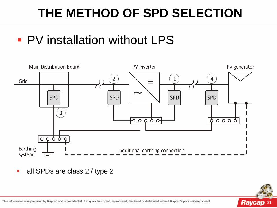
THE METHOD OF SPD SELECTION
PV installation without LPS
all SPDs are class 2 / type 2

32
THE METHOD OF SPD SELECTION
2 & 3: class 1 / type 1 SPD
1 & 4 class 2 / type 2 SPD
PV installation with LPS

33
THE METHOD OF SPD SELECTION PV installation with LPS (safety distance is not kept)
2 & 3 always class 1 / type 1 SPD
if only SPD at location 1: class 2 / type 2 SPD
1 & 4 class 1 / type1 SPD

34
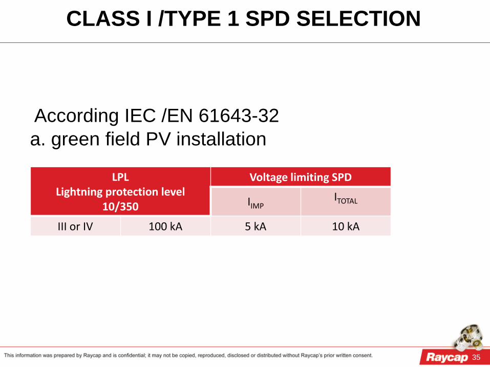
Scenarios to select Class 1/Type 1 SPD: 1. According IEC/EN 62305 series: if no risk assesment is calculated, the minimum partial lightning current for class 1/Type 1 SPD is 12,5kA (10/350); 2. According IEC /EN 61643-32 a. green field PV installations b. roof PV installations
CLASS I /TYPE 1 SPD SELECTION
35
According IEC /EN 61643-32 a. green field PV installation
LPL Lightning protection level
10/350
Voltage limiting SPD
IIMP ITOTAL
III or IV 100 kA 5 kA 10 kA
CLASS I /TYPE 1 SPD SELECTION

36
According IEC /EN 61643-32 b. roof PV installations
LPL Lightning protection
level 10/350
Number of external down-conductors < 4 ≥ 4
IIMP ITOTAL IIMP ITOTAL
I 200 kA 10 kA 20 kA 5 kA 10 kA II 150 kA 7,5 kA 15 kA 3,75 kA 7,5 kA III 100 kA 5 kA 10 kA 2,5 kA 5 kA
CLASS I /TYPE 1 SPD SELECTION
37
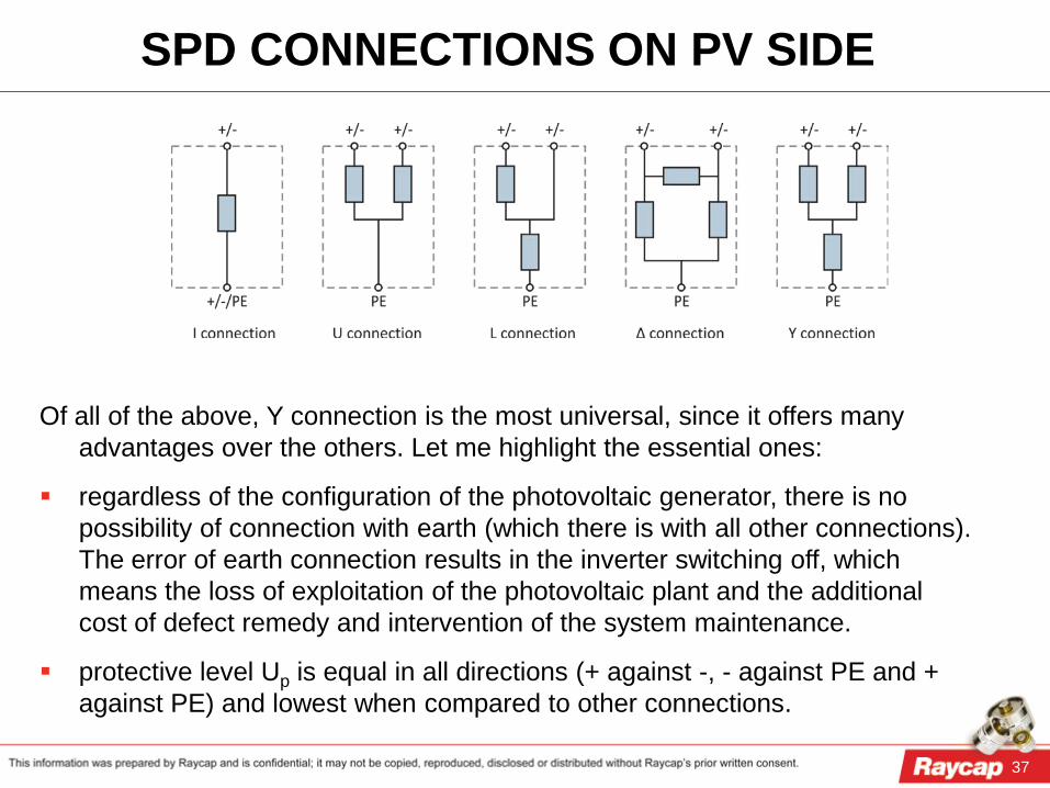
SPD CONNECTIONS ON PV SIDE
Of all of the above, Y connection is the most universal, since it offers many advantages over the others. Let me highlight the essential ones:
regardless of the configuration of the photovoltaic generator, there is no possibility of connection with earth (which there is with all other connections). The error of earth connection results in the inverter switching off, which means the loss of exploitation of the photovoltaic plant and the additional cost of defect remedy and intervention of the system maintenance.
protective level Up is equal in all directions (+ against -, - against PE and + against PE) and lowest when compared to other connections.