spc4000 pressure calibrator - scanivalvescanivalve.com/media/3767/spc4000_revb.pdf · is...
TRANSCRIPT

SPC4000Pressure Calibrator
Operation Manual(revision B)

v
SPC4000 Table of Contents
TABLE OF CONTENTSPREFACE� viii
Warnings, Cautions and Notes viiiWarranty viiiTrademarks ® and Copyrights © ixPackaging for Shipment ixImportant Notice ixContact Information ix
Section�1:�Introduction� 1System Overview 1Unpacking The SPC4000 System 1SPC4000 Front Panel 2SPC4000 Rear Panel 2SPC4000 Display 3SPC4000 Electrical Module 4SPC4000 Pneumatic Module 4SPC4000 Chassis Assembly 5SPCPLU Overview 7SPCPLU Front Panel 8SPCPLU Rear Panel 8
Section�2:�Specifications� 9General Specifications- SPC4000 9General Specifications - SPCPLU 9Control Specifications for Pump Regulator 10Control Specifications for Solenoid Valve Regulator 10Measure Specifications 11
Section�3:�Installation� 12Mounting 12Pneumatic Connections 12Supply Port 12Exhaust Port 13Vent Port 13SPCPLU Static Port 13SPCPLU Solenoid Supply Port 13SPCPLU Cal Out Port 13SPCPLU Ref Out Port 13Digital I/O Connections 13Communications Connections 13Power Up! 14System Operation and Leak Check 14
vi
SPC4000Table of Contents
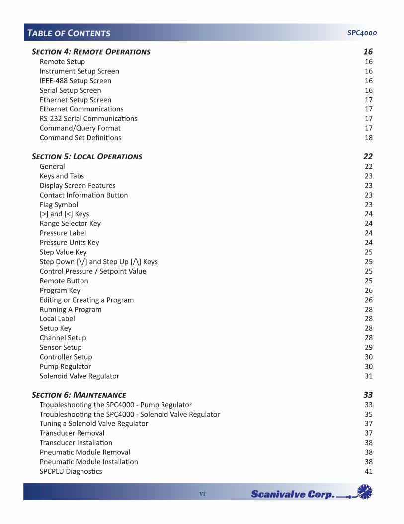
Section�4:�Remote�Operations� 16Remote Setup 16Instrument Setup Screen 16IEEE-488 Setup Screen 16Serial Setup Screen 16Ethernet Setup Screen 17Ethernet Communications 17RS-232 Serial Communications 17Command/Query Format 17Command Set Definitions 18
Section�5:�Local�Operations� 22General 22Keys and Tabs 23Display Screen Features 23Contact Information Button 23Flag Symbol 23[>] and [<] Keys 24Range Selector Key 24Pressure Label 24Pressure Units Key 24Step Value Key 25Step Down [\/] and Step Up [/\] Keys 25Control Pressure / Setpoint Value 25Remote Button 25Program Key 26Editing or Creating a Program 26Running A Program 28Local Label 28Setup Key 28Channel Setup 28Sensor Setup 29Controller Setup 30Pump Regulator 30Solenoid Valve Regulator 31
Section�6:�Maintenance� 33Troubleshooting the SPC4000 - Pump Regulator 33Troubleshooting the SPC4000 - Solenoid Valve Regulator 35Tuning a Solenoid Valve Regulator 37Transducer Removal 37Transducer Installation 38Pneumatic Module Removal 38Pneumatic Module Installation 38SPCPLU Diagnostics 41

vii
SPC4000 Table of Contents
Section�7:�Calibration� 43General 43Environment 43Pressure Standards 43Media 43Setup 43Password 44Restoring Factory Calibration 45On-Site Calibration 451 Point Calibration 472 Point Calibration 48Head Pressure Correction 49
Appendix� 51Measurement Units 51Conversion Factors, PSI 52Conversion Factors, Millitorr 53Conversion Factors, Pascal 54

1
SPC4000 Section 1: Introduction
SECTION�1:�INTRODUCTIONSystem�OverviewThe SPC4000 calibration system consists of three compo-nents; the SPC4000 calibrator, the Pneumatic Logic Unit (SPCPLU) and PressCal, Scanivalve’s free calibration soft-ware.
The Scanivalve SPC4000 Pressure Calibrator is a multi-channel, multi-range pressure system based off of Mensor’s CPC6000. It is designed to test and calibrate all of Scani-valve’s pressure measurement equipment. The SPC4000 can have two independent control channels, each with its own pressure regulator. Each control channel can have up to two transducers.
Scanivalve’s Pneumatic Logic Unit (SPCPLU) is a compliment to the SPC4000 Pressure Calibrator and allows the SPC4000 to perform automated calibrations on any DSA or ZOC modules.
Scanivalve’s PressCal calibration software is included with the purchase of every SPC4000 and is capable of control-ling the SPC4000, the SPCPLU and communicating with the Scanivalve module being calibrated.
The SPC4000 system (SPC4000 calibrator and SPCPLU) is capable of calibrating multiple modules of different ranges during the same automated calibration without any opera-tor intervention.
Unpacking�The�SPC4000�SystemUpon receiving your SPC4000 system, the first thing you should do is to unpack, inventory and inspect all of the included components of the SPC4000 system. Before it left the Scanivalve factory, the SPC4000 system was subjected to many hours of testing and inspection. Please look over all included components and inspect for any damage that might have occurred during shipping. Report any visible damages to the shipper and to Scanivalve immediately. Once you have inspected all included components for any signs of damage, it is important that you do an inventory check and ensure that all components and accessories were included in the shipment. The shipment should include:
1) SPC4000 Calibrator2) Pneumatic Logic Unit (SPCPLU)3) Rack Mount Fixture
• Main rack mount assembly • Foam padding • Mounting hardware (6 #10x1/4” screws)
4) Certificate of calibration5) Digital Out cable 155662-01 (1 or 2)6) Power Cord7) Swagelok® to bulge-tube adaptors (1/8” & 1/16”)8) Helical spring-clamps (1/8” & 1/16”)9) Nylon tubing (25’ - 1/8”; 25’ - 1/16”)10) PressCal installation CD11) SPC4000 Resource CD
Figure�1.1�-�Scanivalve�SPC4000�front�panel

2
SPC4000Section 1: Introduction
SPC4000�Front�PanelThe SPC4000 front panel includes and 8.4 inch color SVGA display featuring touch screen technology. Operator input is accomplished by pressing the words or symbols pre-sented on the display. There are no discrete keypads or switched on the front panel. On the right hand side of the front panel there is a clear window which shows the cali-brated pressure ranges of the internal transducers and the calibrator serial number.
To gain access to the internal modules simply loosen the two thumb screws on the right hand edge of the front panel and swing it open (Figure 1.2). In the front of the instrument directly below the electrical module are slots to accommodate two pressure transducer modules on each control channel. Each transducer can be removed and reinstalled through the front panel opening. See Section 6: Maintenance, for additional information on module removal and replacement.
SPC4000�Rear�PanelUp to eight pneumatic pressure ports are located horizon-tally across the rear panel (Figure 1.3). Positioned to the right of the pressure ports are the Ethernet and RS-232 connectors, the off/on switch, the line fuses, and a protec-tive grill covering the ventilating fan.
Figure 1.3 shows a rear panel containing two solenoid valve regulator pneumatic modules. Rear panels may differ slightly depending on what modules are installed.
Figure�1.3�-Rear�Panel
Figure�1.2�-�Internal�Access

3
SPC4000 Section 1: Introduction
SPC4000�DisplayWhen the SPC4000 is powered up it takes about one minute for initialization, then it displays a screen similar to Figure 1.4. The display is made up of rectangles which display text or symbols.
Keys, Tabs, Labels and Windows: In this manual a key is a small rectangle which acts as a switch when pressed. Keys have borders with a three dimensional, shadowed effect. Tabs are a group of touch points, each of which will overlay most of the screen with one page related to its title subject. Small rectangles with solid borders that display informa-tion, but do not respond to being touched, are called Labels or Windows.
Keys: Keys cause something to change when they are touched. Throughout this manual keys are represented with the displayed characters enclosed in brackets such as [PSI A]. Each key has a characteristic response when actuated; either an instant, single step response when the key is pressed, or continuously repeating steps while the key is held down, or a delayed response when released. Operators will quickly become accustomed to the particu-lar characteristics of the frequently used keys. Some keys become labels under certain conditions, then resume their key function in other circumstances.
Header Bar: The bar across the top of the screen which displays the Mensor Logo, a title frame, and a national flag is stationary and remains displayed at all times. All of the number formats and text displayed on the SPC4000 screens will be in the language appropriate to the national flag dis-played here such as American English for the USA flag, etc. Touch the flag to access a drop-down window showing all of the languages programmed into the SPC4000. Touch any flag to change the display to the corresponding language.
Optional Display: The optional display is a window near the pressure label. This window can be set up to be blank, or to display any one of the following:
• Peak Pressure – minimum and maximum• Rate of change of a measured pressure• Barometer reading
Footer Keys: Like the top bar, the [Remote] and [Program] keys on the bottom left corner of the display remain per-manently on-screen. Touching either of these keys will cause that subject page to appear in the display.
Figure�1.4�-�Terminology�of�Screen�Elements

4
SPC4000Section 1: Introduction
SPC4000�Electrical�ModuleThe electrical module is illustrated below with the instru-ment lid removed (Figure 1.5). All program information to run the system resides on a solid state disk module located on this module. The power switch and line fuses are situ-ated on the rear of the electrical module such that they are accessible on the rear of the fully assembled SPC4000.
SPC4000�Pneumatic�ModulePneumatic modules come in two types and are referred to in this manual as the “Pump Regulator” or the “Solenoid Valve Regulator”. The pump regulator is used with low pressure sensors specified in Section 2: Specifications. The solenoid valve regulator is used with higher pressure sen-sors and comes in three varieties:
High Pressure Solenoid Valve Regulator (HPSVR)Medium Pressure Solenoid Valve Regulator (MPSVR)Low Pressure Solenoid Valve Regulator (LPSVR)
Pressure limits for all of these are specified in Section 2: Specifications.
Each pneumatic module (Figure 1.6) includes platforms for up to two high performance pressure transducers which are traceable to NIST standards. Both of these transducers can be used in conjunction with the highly stable pres-sure regulator to produce a precise pressure output. Each transducer includes its own on-board compensation and calibration data so that any transducer can be replaced in the instrument without requiring a recalibration.
Figure�1.5�-�Electrical�Module
Figure�1.6�-�Pneumatic�Module

5
SPC4000 Section 1: Introduction
SPC4000�Chassis�AssemblyThe chassis assembly acts as the housing for the system. The electrical and pneumatic modules are each self-con-tained inside the chassis, and either can be replaced using basic hand tools. In addition, each pressure transducer is individually removable without tools. Instructions for transducer and module removal are provided in Section 6: Maintenance.
The only moving parts in the SPC4000 are the fan, the pneumatic flow controller diaphragms and valves, the pump/motor, and the solenoid valve plungers. There are no internal user adjustments or setup switches.
Figure�1.7�-�Chassis�Assembly

6
SPC4000Section 1: Introduction
Figure�1.8�-�SPC4000�Electrical�Block�Diagram

7
SPC4000 Section 1: Introduction
SPCPLU�OverviewThe Pneumatic Logic Unit (SPCPLU) is required for auto-mated calibrations of DSA and ZOC modules. The SPCPLU is designed to orchestrate all of the pneumatic switching required during the calibration. It contains all required pneumatic solenoid valves and manifolds required to perform both single and multi-range calibrations as well as zero offset corrections. The SPCPLU is dependant on the SPC4000 for configuration and is controlled by 3 digital outputs per channel from the SPC4000.
The SPCPLU is capable of segregating four individual calibration pressure ranges to allow modules of varying pressure ranges to be calibrated together during a single automated calibration procedure. Figure 1.9 depicts the internal pneumatic logic of the SPCPLU as well as how it interacts with the SPC4000 calibrator and the module being calibrated
ZERO CALVALVE
CAL/REFSELECTION
VALVE
DSAZOC
CAL
REF
SPC4000CALIBRATOR
MEASUREMENTCONTROL
(OUT)
REFERENCE
BAROMETER ORREMOTE LOCATION
(STATIC)
90PSICONTROL
SUPPLY
DOUT2 DOUT1
LOGIC TABLE
SOLENOIDVALVE
SCANIVALVEUNIT TO BE
CALIBRATEDSPCPLU
PILOTVALVES
OPERATE = DOUT1 OFF DOUT2 OFF
POSITIVE = DOUT1 OFFCALIBRATION DOUT2 OFF
NEGATIVE = DOUT1 ONCALIBRATION DOUT2 ON
ZERO = DOUT1 ONCALIBRATION DOUT2 OFF
Figure�1.9�-�SPCPLU�Pneumatic�Logic

8
SPC4000Section 1: Introduction
SPCPLU�Front�PanelThe front panel of the SPCPLU (Figure 1.10) displays its current configuration using 6 LEDs. Each of the LEDs represent the current state of each one of the internal solenoid valves. Included on the front panel of the SPCPLU is a truth table explain-ing each of the SPCPLU’s configurations and the digital outputs associated with each.
SPCPLU�Rear�Panel
All of the pneumatic interfaces for the SPCPLU are located on the rear panel of the SPCPLU (Figure 1.11). These include input pressures, control pressure inputs, reference output and calibration output. Also located on the rear panel of the SPCPLU are the digital input/output connections. Each of the pneumatic fittings on the rear of the SPCPLU are 1/4” Swagelok® fit-tings. It is important that any pneumatic input or output not being used should be plugged.
SPC4000�System�OverviewIn order to fully exploit the capabilities of the SPC4000 calibrator, it must be used in the SPC4000 system which includes the SPCPLU and PressCal software. Figure 1.12 shows the SPC4000 mounted in a standard 19” rack with the SPCPLU. This configuration allows fully automated, multiple range calibrations to be performed.
Figure�1.11�-�SPCPLU�Rear�Panel
Figure�1.10�-�SPCPLU�Front�Panel
Figure�1.12�-�SPC4000�System

9
SPC4000 Section 2: Specifications
SECTION�2:�SPECIFICATIONSGeneral�Specifications-�SPC4000Size (WxHxD) 14.02” x 7.55” x 14.42” (35.61 cm x 19.2 cm x 31.55 cm)
Weight 36lbs - with all internal options (16.33 kg)
Power Requirements 100-240 VSC, 47-63 Hz, 75VA max
Digital I/O
Pneumatic Interfaces 1/4” Swagelok®
Particle Filters The instrument has 20-micron filters on all pressure ports through the manifold. The baro metric transducer has no filters.
Overpressure Protected by relief valves.Protection
CompensatedTemperature 15°C to 45°CRange
Operating Temperature 0°C to 50°C Range
StorageTemperature 0°C to 70°CRange
Local User Interface 8.4” color LCD display with 8 wire resistive touch screen.
Remote User Interface Serial RS-232, Ethernet
Warm-up Period Approximately 30 minutes for full accuracy
Orientation Effects Negligible
Operating 5 to 95% RH non-condensingEnvironment
General�Specifications�-�SPCPLUSize (WxHxD) 19” x 3.5” x 13” (48.3 cm x 8.9 cm x 33 cm)
Weight 6.9 lbs - SPCPLU-1 (3.13 kg) 11.5 lbs - SPCPLU-2 (5.22 kg)
Pneumatic Interfaces 1/4” Swagelok®
Control Pressure SPCPLU-1 & -2 90-120 psi - user supplied SPCPLU-3 & -4 60-70 psi - user supplied

10
SPC4000Section 2: Specifications
Control�Specifications�for�Pump�RegulatorSource Requirements Fast Mode Slow Mode
Stability of Controlled Pressure
Available Sensor Range
Minimum Controlled Pres-sure
Control Time Fast Mode
Slow Mode
Supply Consumption Fast Mode
Slow Mode
Measure to Control Offset
Overshoot
110% of highest pressureNone
0.003% of span, typically better than 0.001% of span 10 seconds after displaying stable flag.
0-.36 psig to 0-15 psig
0.05% FS or 0.5 psi over exhaust pressure, which-ever is greater
10 seconds to stable flag for 10% FS step pressure change into 50cc volume. Larger volumes can lengthen this time. 15 seconds to stable flag for 10% FS step pressure change into 50cc volume. Larger volumes can lengthen this time.
Zero after set point is reached. All supply gas is used for upscale pressure sample filling.Zero
<0.0005% Span
<1% of active range
Control�Specifications�for�Solenoid�Valve�RegulatorSource Requirements
Stability of Controlled Pressure
Available Sensor Range LPSVR MPSVR HPSVR
Minimum Controlled Pres-sure
Control Time
Supply Consumption
Overshoot Low overshoot mode High speed mode
110% of highest pressure or 20 psi over highest pres-sure transducer, whichever is less
0.003% of span, typically better than 0.001% of span 10 seconds after displaying stable flag.
0-1 psig to 0-50 psig0-10 psig to 0-150 psig0-75 psig to 0-850 psig
0.05% FS or 0.25 psi over exhaust pressure, which-ever is greater
10 seconds to stable flag for 10% FS step pressure change into 50cc volume. Larger volumes can lengthen this time.
<2.5 scfh in steady-state mode
<0.005%
<1.00%

11
SPC4000 Section 2: Specifications
Measure�SpecificationsAccuracy ±0.01% FS
Calibration Period 365 days (15 psi +) 180 days (0-14.9 psi)
Precision 0.003% of span
Pressure Ranges *** 0.36 psig 1 psig 5 psig 15 psig 50 psig 100 psig 200 psig 500 psig 750 psig 850 psig
Resolution 4 to 6 significant digits, user selectable
Optional Barometer 11 to 17 psiaRange
Optional Barometer ±0.01% FSUncertainty
Optional Barometer 180 daysCalibration Period
Pressure Media Clean, dry, non-corrosive, non- combustible, non-oxidizing gases. Not for oxygen use.
*** Nominal pressure ranges listed. Actual transducer pressure range will be 10-20% greater.
12
SPC4000Section 3: Installation
SECTION�3:�INSTALLATIONMountingThe SPC4000 system is intended to be mounted in a stan-dard 19” rack. If desired however, it can be used in a bench top application. Installing the SPC4000 system into a rack requires the rack mount (included). The SPC4000 and the SPCPLU must be installed in the rack mount before being installed in a 19” rack.
The special sensors used in the SPC4000 are relatively insensitive to tilt and vibration. However to further assure stability and accuracy, avoid mounting the instrument on surfaces subject to excessive motor or machinery vibration.
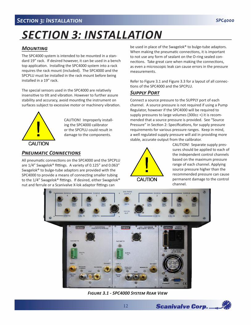
Pneumatic�ConnectionsAll pneumatic connections on the SPC4000 and the SPCPLU are 1/4” Swagelok® fittings. A variety of 0.125” and 0.063” Swagelok® to bulge-tube adaptors are provided with the SPC4000 to provide a means of connecting smaller tubing to the 1/4” Swagelok® fittings. If desired, either Swagelok® nut and ferrule or a Scanivalve X-lok adaptor fittings can
be used in place of the Swagelok® to bulge-tube adaptors . When making the pneumatic connections, it is important to not use any form of sealant on the O-ring sealed con-nections. Take great care when making the connections, as even a microscopic leak can cause errors in the pressure measurements.
Refer to Figure 3.1 and Figure 3.3 for a layout of all connec-tions of the SPC4000 and the SPCPLU.
Supply�PortConnect a source pressure to the SUPPLY port of each channel. A source pressure is not required if using a Pump Regulator, however if the SPC4000 will be required to supply pressures to large volumes (300cc +) it is recom-mended that a source pressure is provided. See “Source Pressure” in Section 2: Specifications, for supply pressure requirements for various pressure ranges. Keep in mind, a well regulated supply pressure will aid in providing more stable, accurate output from the calibrator.
CAUTION! Improperly install-ing the SPC4000 calibrator or the SPCPLU could result in damage to the components.
CAUTION! Separate supply pres-sures should be applied to each of the independent control channels based on the maximum pressure range of each channel. Applying source pressure higher than the recommended pressure can cause permanent damage to the control channel.
Figure�3.1�-�SPC4000�System�Rear�View

13
SPC4000 Section 3: Installation
Measure/Control/Cal�PortThe Measure/Control/Cal port is the output pressure from the SPC4000 calibrator. Connect this port to the ‘Cal In’ port on the SPCPLU for the related channel. In addition to outputting a precisely controlled pressure out of this port, when the SPC4000 is in ‘Measure’ mode, the calibrator will measure and display the pressure at this port.
A pressure value can be selected using the on-screen keypad. That pressure will then be output to the MEASURE/CONTROL/CAL port by switching to the CONTROL mode of operation.
Exhaust�PortIf sub-atmospheric control pressure is required a vacuum pump must be connected to the EXHAUST port. Otherwise, this port may be left open to atmosphere.
Reference/Static�PortThis port is connected to the reference side of the trans-ducer. This port is normally left open to atmosphere but should be connected to a known reference or static source for low pressure calibrations.
Vent�PortBuilt up calibration pressure is vented through this port. It can be left open to local atmosphere, or it can be routed to a remote venting location.
SPCPLU�Static�PortThe SPCPLU has an individual static port for each range. This port is used when a zero calibration is performed on the Scanivalve module being calibrated. It should be plumbed to the same location as the reference/static port
on the SPC4000 calibrator is plumbed to. That is, for low pressure modules, to some form of stable static reference location and for higher pressure modules left open to local atmosphere. Either case, it is very important that the SPCPLU static port and the SPC4000 reference/static port are tied to the same location. If any of the Static Ports are not being used, ensure that the fitting is plugged.
SPCPLU�Solenoid�Supply�PortThere is one solenoid supply port on the SPCPLU. This is the supply pressure for the pneumatic solenoids within the SPCPLU. It is very important that adequate control pres-sure is supplied to the SPCPLU (90psi for SPCPLU-1&-1, 60psi for SPCPLU-3&-4 minimum). Anything less than this may not be sufficient for proper function and switching of the internal pneumatic solenoids.
SPCPLU�Cal�Out�PortEach range on the SPCPLU has a dedicated Cal Out port. This is the calibration port that needs to be connected to the positive calibration port on the module being cali-brated. If any of the Cal Out ports are not being used, ensure that the fitting is plugged.
SPCPLU�Ref�Out�PortEach range on the SPCPLU also has a dedicated Ref Out Port. This needs to be connected to the negative, or refer-ence calibration port on the module being calibrated. If any of the Ref Out ports are not being used, ensure that the fitting is plugged.
Digital�I/O�ConnectionsAfter all pneumatic connections have been made, connect the Digital Output(s) from the SPC4000 calibrator to the Digital Input(s) on the SPCPLU. These Digital I/O’s allow the SPC4000 calibrator to communicate with and control the SPCPLU. Make sure that the Digital I/O’s are connected to the correct output channel from the SPC4000. Range 1 & 2 on the SPCPLU must be connected to Digital I/O’s of Chan-nel A on the SPC4000, and range 3 & 4 on the SPCPLU must be connected to Channel B.
Communications�ConnectionsIf the SPC4000 system is to be operate remotely, com-munications connections must be made to the SPC4000. Connect either an Ethernet cable to the Ethernet port, or a serial cable to the RS-232 port. For more information on remote communications with the SPC4000, see Section 4: Remote�Operations.
WARNING! HIGH NOISE LEVELS! As pressure decreases com-pressed gas will escape out the exhaust port. For ranges above 500 psi high noise levels may result during such pressure releases. To overcome objection-able exhaust noise either install a muffler or route the port to a remote location.
CAUTION! Improper use of this equipment may impair protection provided by this instrument.
14
SPC4000Section 3: Installation
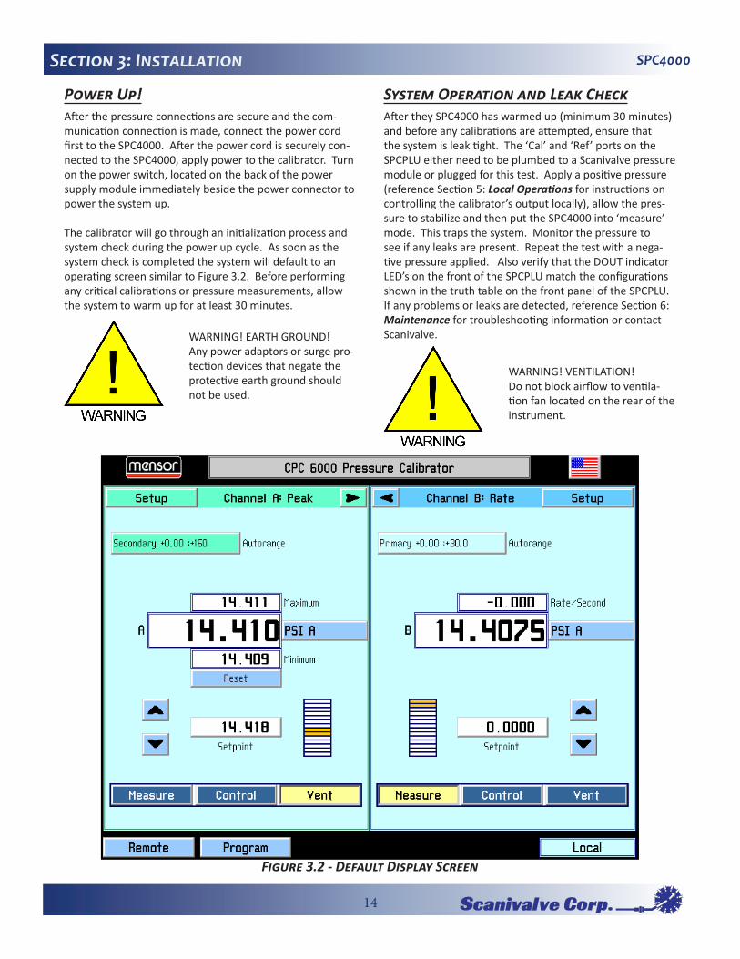
Power�Up!After the pressure connections are secure and the com-munication connection is made, connect the power cord first to the SPC4000. After the power cord is securely con-nected to the SPC4000, apply power to the calibrator. Turn on the power switch, located on the back of the power supply module immediately beside the power connector to power the system up.
The calibrator will go through an initialization process and system check during the power up cycle. As soon as the system check is completed the system will default to an operating screen similar to Figure 3.2. Before performing any critical calibrations or pressure measurements, allow the system to warm up for at least 30 minutes.
System�Operation�and�Leak�CheckAfter they SPC4000 has warmed up (minimum 30 minutes) and before any calibrations are attempted, ensure that the system is leak tight. The ‘Cal’ and ‘Ref’ ports on the SPCPLU either need to be plumbed to a Scanivalve pressure module or plugged for this test. Apply a positive pressure (reference Section 5: Local�Operations for instructions on controlling the calibrator’s output locally), allow the pres-sure to stabilize and then put the SPC4000 into ‘measure’ mode. This traps the system. Monitor the pressure to see if any leaks are present. Repeat the test with a nega-tive pressure applied. Also verify that the DOUT indicator LED’s on the front of the SPCPLU match the configurations shown in the truth table on the front panel of the SPCPLU. If any problems or leaks are detected, reference Section 6: Maintenance for troubleshooting information or contact Scanivalve.WARNING! EARTH GROUND!
Any power adaptors or surge pro-tection devices that negate the protective earth ground should not be used.
WARNING! VENTILATION!Do not block airflow to ventila-tion fan located on the rear of the instrument.
Figure�3.2�-�Default�Display�Screen

15
SPC4000 Section 3: Installation
Figu
re�3.3�-�SP
C400
0�/�SP
CPLU
�Con
nections

16
SPC4000Section 4: Remote Operations
SECTION�4:�REMOTE�OPERATIONSRemote�SetupUse the following screens to set the operating parameters for the Ethernet and RS-232 serial ports.
Press the [Remote] key located on the bottom left corner of the screen, and a new display appears with another set of tabs across the top as shown in Figure 4.1.
Instrument�Setup�ScreenPress the [Instrument] tab to set up available emulation modes. The default command set is Mensor.
[A] [B] (channel selection): This channel selection sets the active remote channel to A or B and is useful for customers using an SPC4000 to replace two single channel controllers. The user can simply select the channel here first and then begin their normal program.
[Monitor] key: Press the [Monitor] key to bring up the remote monitor window (Figure 4.2) which displays cur-rent remote activity and syntax errors. This is helpful when troubleshooting programs.
IEEE-488�Setup�ScreenThe IEEE-488 function is not available on the SPC4000 cali-brator so this screen is extraneous and can be ignored.
Serial�Setup�ScreenPress the [Serial] tab to set up the serial port parameters (Figure 4.3). These parameters should be set up to match your host computer. Default settings are: 57600, 8,1, none parity, and no echo.
If the Echo check box is checked, the SPC4000 will immedi-ately echo back characters sent over the serial port.
Figure�4.1�-�Instrument�Setup�Screen
Figure�4.2�-�Monitor�Window
Figure�4.3�-�Serial�Setup�Screen

17
SPC4000 Section 4: Remote Operations
Ethernet�Setup�ScreenPress the [Ethernet] tab to set up the Ethernet parameters (Figure 4.4). These parameters should be set up to match your host computer.
When the correct values have been selected for all four parameters simply touch any of the keys across the top or the bottom of the screen to move on to another function.
Ethernet�CommunicationsThe Ethernet communication port allows the SPC4000 to communicate with computers using 10/100Based-T speci-fications. Ethernet communications are transmitted over a standard RJ-45 cable.
Connecting directly to a PC requires a crossover Ethernet cable. Hub connection requires a straight Ethernet cable.
Prior to first time use of Ethernet communication, the four parameters, IP, Netmask, Gateway, and Port must be setup.
RS-232�Serial�CommunicationsThe serial communication port allows the SPC4000 to com-municate in RS-232 format with computers, terminals, or similar hosts.RS-232 communications are transmitted over a three conductor, shielded cable terminated in a standard DB9S connector on the instrument end, and typically the same connector on the host end. Figure 4.5 illustrates the proper pin-outs. Notice that each pin 2 is connected to pin 3 on the opposite end. This configuration is commonly referred to as a 9-pin null modem cable.
Command/Query�FormatCommands must be sent in ASCII format and terminated with either a carriage return (<cr>), linefeed (<lf>) or both. Commands are not case sensitive. Each query returns a response. If an error is detected the response will include an error flag.
One of the first commands issued when starting remote communications should be “Keylock Yes”. This will disable the on-screen keys and tabs, and place the “Keylock” label on the screen. Turning keylock on prevents the potential conflicts that could occur if someone pressed an on-screen key, either intentionally or by accident.
Command/Query Field: Unless otherwise specified, com-mands are typically converted to queries by appending a question mark to the command. Table 4.1 lists all of the SPC4000 command/query keywords.
Data Field: The data field is either in ASCII {string} or numeric {value} form. In the case of multiple data fields, commas are required to separate the fields. Queries do not have a data field. String (text) or value (numeric) data are acceptable in any of the following formats:
Examples of {string} data: ON OFF mBar Examples of {value} data: 1 1.0 -5.678
Figure�4.4�-�Ethernet�Setup�Screen
CAUTION! Please consult your Computer Resources Department prior to connecting this instru-ment to your network to verify there are no conflicts with exist-ing IP addresses.
Figure�4.5�-�Serial�Cable

18
SPC4000Section 4: Remote Operations
Command�Set�DefinitionsIn this manual a data entry made up of alpha characters is defined as a string, as opposed to data containing only numbers, such as “Enter 1 for ON or 0 for OFF” where 1 and 0 are defined as values.
Command: Any command or query listed in Table 4.1.
Separator: Space <SP>.
Data: ASCII representations of numbers, {value}, or alpha characters, {string}, data as defined above. When sending code a literal variable replaces the braces and the enclosed character(s) shown in the following examples.
Termination: Linefeed (LF) or carriage return (CR) is used to signal the end of a command statement.
Always send commands in one of the following formats:
1. [Command] [Termination];2. [Command] [Separator] [Data] [Termination];3. Queries are special instructions in the form:
[Command?] [Termination] where the question mark, “?”, immediately precedes the terminator.
When a valid query is received, the SPC4000 will return {data} terminated by CR and LF.
Floating point data is returned in the current engineering units in exponential format.
Channel specific commands are sent to only the active channel. See ‘CHANNEL’ command. Exceptions are GP, GN, RP, RP/C, IC and ZO commands when preceded by a specific range/transducer number.
Commands that are included in the “Scanivalve” command set are specific to the SPC4000 and are indicated in the following table in bold font. When any of these commands are received, the SPC4000 will return a prompt as defined by the current setting of the “SM” command.

19
SPC4000 Section 4: Remote Operations
Table 4.1 - SPC4000 Commands and QueriesCommand Data Function / Response
Autozero none Re-zero all ranges that can measure the vented pressure. These adjustments are not password protected and are not saved through power cycles. This command takes approximately 60 seconds.
Autozero? S,T,X,X Returns autozero data where S represents state (responses can be 0 = complete, 1 = local autozero, or 2 = remote autozero), T represents the estimated remaining time to complete in sec-onds, and X is a (0) character since this data location is not used at this time.
Autozero-abort
none Aborts autozero.
Baro? <sp>{value}<cr><lf> Returns reading from barometric sensor.Channel {A or B} Sets the active channel on the instrument.Chan? <sp>{A or B}<cr><lf> Returns which channel is active.Decpt <sp>{4, 5 or 6}<cr><lf> Sets the number of significant digits displayed.Decpt? <sp>{value}<cr><lf> Returns the number of significant digits displayed for the active
channel.Default none Sets the default values. This command takes approximately 20
seconds.Error? <sp>{string}<cr><lf> Returns a description of an error.Errorno? <sp>{string}<cr><lf> Returns SPC4000 error code and text.Filter {Off, Low, Normal, High} Sets the reading filter.Filter? <sp>{string}<cr><lf> Returns the reading filter.GN <sp>{value} Sends the SPC4000 to control mode and a desired negative
pressure (value). Precede with a 1, 2, 3 or 4 for a specific range.EX: 2gn 10
GP <sp>{value} Sends the SPC4000 to control mode and a desired positive pressure (value). Precede with a 1, 2, 3 or 4 for a specific range.EX: 3gp 53.47
IC none Places the specified channel in a “trap” mode closing all valves internally in the SPC4000 including the supply, vent measure/output solenoids. This leaves the module being calibrated in a no-flow condition.Precede with a 1, 2, 3 or 4 for a specific range.EX: 1ic
ID? <sp>MENSOR,600,{ssssss},{v.vv}<cr><lf>
Returns the instrument identity where {ssssss} is the serial number, and {v.vv} is the software version number.
IP {string e.g. nnn.nnn.nnn.nnn} Sets the IP address of the instrument.IP? <sp>{string}<cr><lf> Returns the IP address of the instrument.Keylock {Yes or No} YES to lock, or NO to unlock the on-screen keys.Keylock? <sp>{Yes or No}<cr><lf> Returns current keylock status as YES or NO.

20
SPC4000Section 4: Remote Operations
Table 4.1 - SPC4000 Commands and QueriesCommand Data Function / Response
Listcal? <sp>PRI,{sn},{td},{mm/dd/yyyy},{td},{mm/dd/yyyy};SEC,{td},{mm/dd/yyyy},{td},{mm/dd/yyyy}<cr> <lf>
Returns the serial number of each installed transducer and cali-bration dates for each range.
Listrange? <sp>PRI,{td},{min},{max},{td},{min},{max};SEC,{td},{min},{max},{td},{min},{max}<cr><lf>
Returns the minimum and maximum ranges of all installed sen-sors for the active channel.
Locale? <sp>{string}<cr><lf> Returns current language and Country locale.Meas none Instrument placed in Measure or trap mode.Measure? <sp>{Yes or No}<cr><lf> Returns YES if active channel is in Measure mode; NO if other-
wise.Mode? <sp>{string}<cr><lf> Returns the operation mode of the active channel.Netmask {nnn.nnn.nnn.nnn} Sets the Ethernet network mask.Netmask? <sp>{nnn.nnn.nnn.nnn}<cr><lf> Returns the Ethernet network mask.Peakmax? <sp>{value}<cr><lf> Returns the maximum pressure since peakreset was sent.Peakmin? <sp>{value}<cr><lf> Returns the minimum pressure since peakreset was sent.Peakreset none Resets the peak values.Port {value} Sets the Ethernet port of the instrument.Port? <sp>{value}<cr><lf> Returns the Ethernet port of the instrument.RangeMax? <sp>{value}<cr><lf> Returns the maximum range of the active transducer and turn-
down in the current units.RangeMin? <sp>{value}<cr><lf> Returns the minimum range of the active transducer and turn-
down in the current units.Rdecpt? <sp>{value}<cr><lf> Returns the number of rate decimal points for the active chan-
nel. See: ResolutionRepeat None Repeats output continually over serial port only.Resolution {4 to 6} Sets the number of significant digits. See: decptResolution? <sp>{value}<cr><lf> Returns the number of significant digits.RP None Returns the current pressure read by a transducer. Precede
with a 1, 2, 3 or 4 to specify the transducer being measured.EX: 1RP
RP/C None Continuously returns the current pressure read by a transducer. Precede with a 1, 2, 3 or 4 to specify the transducer being measured.EX: 4RP/C<esc><cr> to terminate
Rsetpt {value} Sets the rate setpoint of the active channel in current units per second. Must be a value inside the current sensor range.
Sbaud {9600, 19200, 38400, 57600} Sets the serial baud rate.Sbaud? <sp>{value}<cr><lf> Returns the serial baud rate.Sdata {7 or 8} Sets the serial data bits.Sdata? <sp>{value}<cr><lf> Returns the serial data bits number.
21
SPC4000 Section 4: Remote Operations
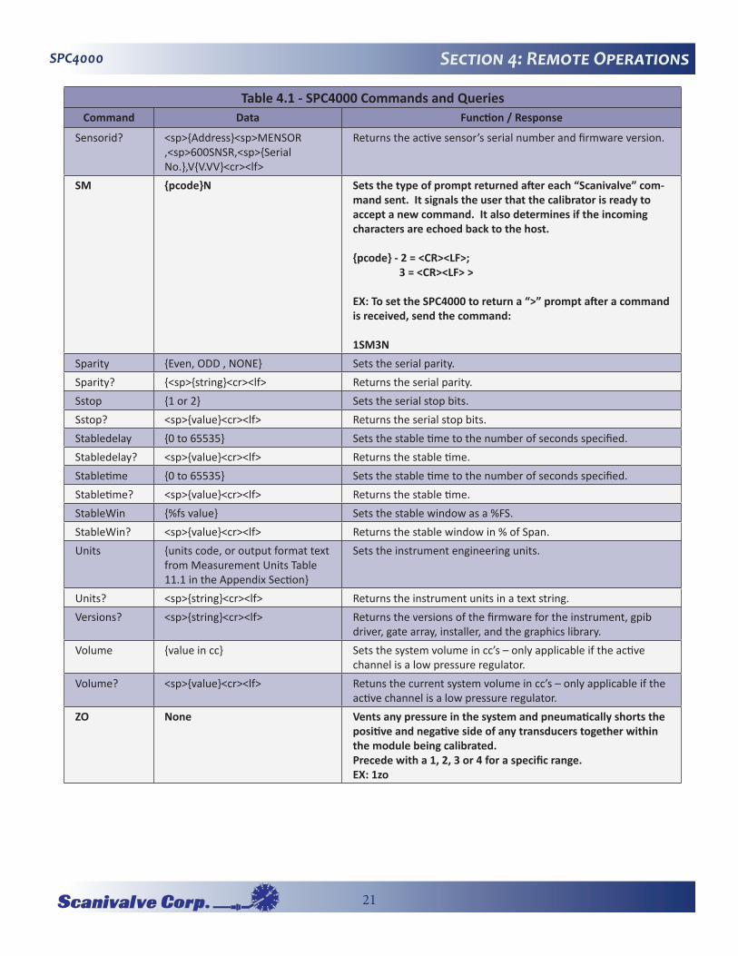
Table 4.1 - SPC4000 Commands and QueriesCommand Data Function / Response
Sensorid? <sp>{Address}<sp>MENSOR ,<sp>600SNSR,<sp>{Serial No.},V{V.VV}<cr><lf>
Returns the active sensor’s serial number and firmware version.
SM {pcode}N Sets the type of prompt returned after each “Scanivalve” com-mand sent. It signals the user that the calibrator is ready to accept a new command. It also determines if the incoming characters are echoed back to the host.
{pcode} - 2 = <CR><LF>; 3 = <CR><LF> >
EX: To set the SPC4000 to return a “>” prompt after a command is received, send the command:
1SM3NSparity {Even, ODD , NONE} Sets the serial parity.Sparity? {<sp>{string}<cr><lf> Returns the serial parity.Sstop {1 or 2} Sets the serial stop bits.Sstop? <sp>{value}<cr><lf> Returns the serial stop bits.Stabledelay {0 to 65535} Sets the stable time to the number of seconds specified.Stabledelay? <sp>{value}<cr><lf> Returns the stable time.Stabletime {0 to 65535} Sets the stable time to the number of seconds specified.Stabletime? <sp>{value}<cr><lf> Returns the stable time.StableWin {%fs value} Sets the stable window as a %FS.StableWin? <sp>{value}<cr><lf> Returns the stable window in % of Span.Units {units code, or output format text
from Measurement Units Table 11.1 in the Appendix Section}
Sets the instrument engineering units.
Units? <sp>{string}<cr><lf> Returns the instrument units in a text string.Versions? <sp>{string}<cr><lf> Returns the versions of the firmware for the instrument, gpib
driver, gate array, installer, and the graphics library.Volume {value in cc} Sets the system volume in cc’s – only applicable if the active
channel is a low pressure regulator.Volume? <sp>{value}<cr><lf> Retuns the current system volume in cc’s – only applicable if the
active channel is a low pressure regulator.ZO None Vents any pressure in the system and pneumatically shorts the
positive and negative side of any transducers together within the module being calibrated.Precede with a 1, 2, 3 or 4 for a specific range.EX: 1zo
22
SPC4000Section 5: Local Operations
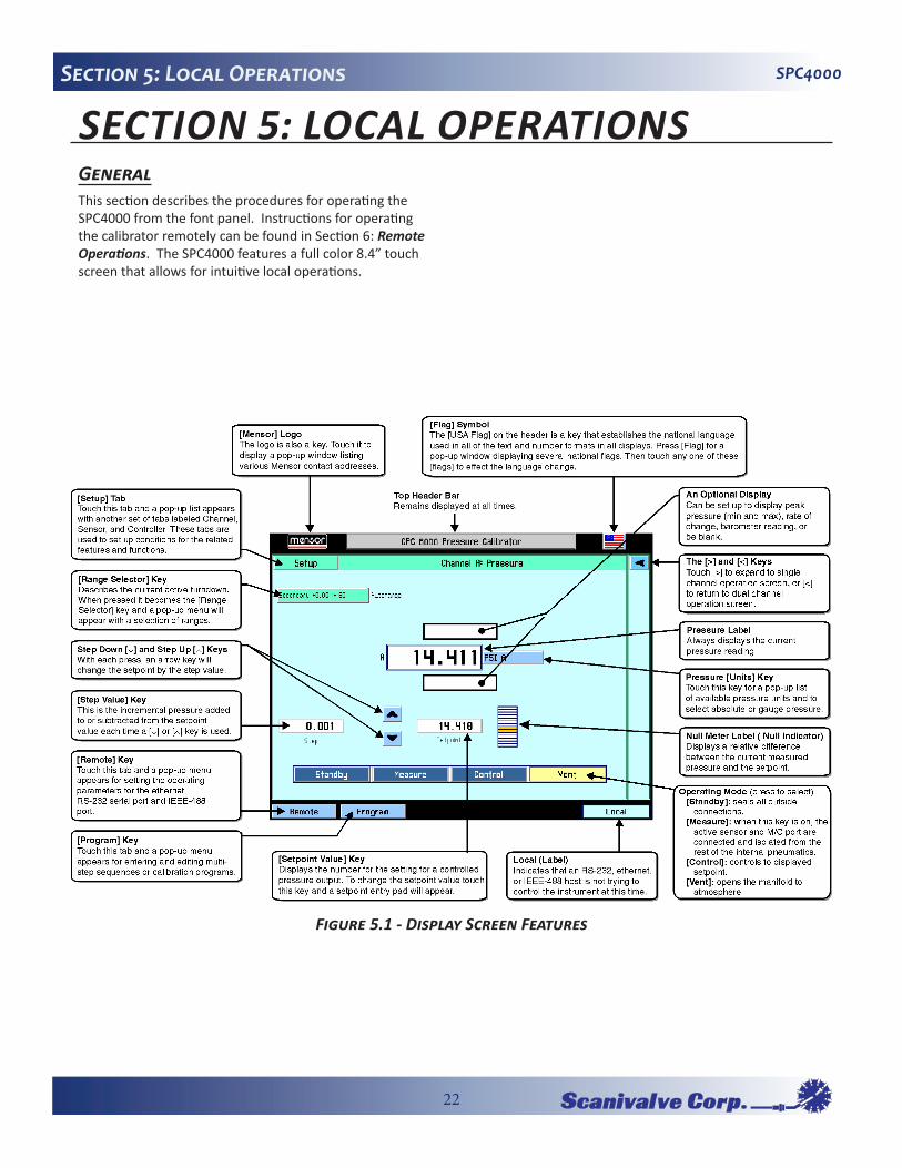
SECTION�5:�LOCAL�OPERATIONSGeneralThis section describes the procedures for operating the SPC4000 from the font panel. Instructions for operating the calibrator remotely can be found in Section 6: Remote�Operations. The SPC4000 features a full color 8.4” touch screen that allows for intuitive local operations.
Figure�5.1�-�Display�Screen�Features

23
SPC4000 Section 5: Local Operations
Keys�and�TabsLocal operation is accomplished by observing the data presented in the display, then pressing the on-screen [key] or [tab] for the desired function. Throughout this manual characters enclosed inside square brackets [ ] represent the associated on-screen touch point.
Display�Screen�FeaturesFigure 5.1 provides a brief description of the features shown on a single channel display.
Figure 5.2 is an example of a typical display after initializa-tion. To expand the selected channel to a single channel operation screen as shown in Figure 5.1, press the [>] key. The [Standby] key appears on the screen when expanded. To expand or return to a dual channel operation screen press the [<] or [>] key.
All of the SPC4000 screen features are described in more detail in the rest of this section.
Contact�Information�ButtonThe logo is also a key. Touch it (Figure 5.3) to display a pop-up window listing various Scanivalve contact informa-tion and SPC4000 serial number and version information. Touch [Close] to close the window.
Flag�SymbolThe [USA Flag] on the header is a key that establishes the national language used in all of the text and number for-mats in all displays. Press the [Flag] for a pop-up window displaying several national flags (Figure 5.4). Touch any one of these [Flags] to effect the language change.
The current language selections available are:
Language Country FlagsEnglish USAGerman GermanyGerman SwitzerlandEnglish Great BritainChinese ChinaEnglish CanadaFrench FranceFrench SwitzerlandEnglish IrelandKorean KoreaFrench CanadaItalian Italy
Russian RussiaPolish Poland
Japanese JapanSpanish MexicoSpanish Spain
Figure�5.2�-�Typical�Operation�Screen
Figure�5.3�-�Contact�Information�Button Figure�5.4�-�Language�Selection�Window

24
SPC4000Section 5: Local Operations
[>]�and�[<]�KeysThe [>] and [<] keys will expand the selected channel to single channel operation screen, or return to dual channel operation screen.
Range�Selector�KeyThe label in the upper left portion of Figure 5.6 describes the current active range as “Secondary +0.00 :+160”. The label , when touched, becomes the [Range Selector] key. Different colors are used to distinguish primary and second-ary transducers. The currently active range is highlighted with a yellow background. Touch any range other than the yellow one to select a different range as shown in Figure 5.7. The last selection in this range selector is [Autorange], which will automatically switch to the most accurate range in the system capable of measuring the current pressure. Each change is immediately reflected in the turndown label. There is also a label beside the current active range to show if you are in range hold or autorange.
Some pressure units can cause a number to be too long for the value window. In those cases the value will be abbrevi-ated with an “m” (milli), “k” (kilo), or “M” (mega) multiplier appended to the range in the range drop list.
An important feature of the SPC4000 is that transducers can easily be changed. A transducer can be replaced in the SPC4000 in less than 30 seconds, with no tools required. Each installed transducer identifies itself to the system using its on-board stored data. Among the items stored in this data are the transducer serial number, curve charac-terizations and calibrations for each turndown, the dates of calibration, and the transducer’s software version.
Pressure�LabelBelow the turndown label shown in Figure 5.6 is a larger label showing the measured pressure value of “14.410”. This large label always displays the current pressure read-ing.
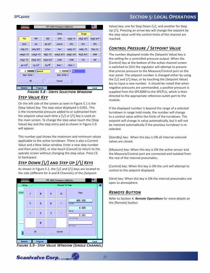
Pressure�Units�KeyTo the right of the pressure label is the [Units] key, shown in Figure 5.6 as [PSI]. Touch [PSI] and a pop-up menu of pressure units will appear as in Figure 5.8. This menu includes [User 1] and [User 2] keys allowing the user to enter customized pressure units. Touch [PSI] and it will toggle to Pascal. Press a [Value] key to enter a custom mul-tiplier to equal either one PSI, or one Pascal, whichever is showing in the user multiplier base units key.
The upper right [absolute] or [gauge] key allows emulation mode if an optional barometric sensor is installed.
The current units are highlighted by a yellow background. Touch any other [Pressure Units] key, and press [OK] to enable change and return to previous operation screen. All of the displayed pressure values will have changed to corre-spond to the newly selected units at the correct conversion ratio.
Figure�5.5�-�Channel�Screen�Selection�Buttons
Figure�5.6�-�Range�Selector�Key
Figure�5.7�-�Range�Selector�drop-down�menu
25
SPC4000 Section 5: Local Operations
Step�Value�KeyOn the left side of the screen as seen in Figure 5.1 is the [Step Value] key. The step value displayed is 0.001. This is the incremental pressure added to or subtracted from the setpoint value each time a [\/] or [/\] key is used on the main screen. To change the step value touch the [Step Value] key and the step entry pad as shown in Figure 5.9 will appear.
This number pad shows the maximum and minimum values applicable to the active turndown. There is also a Current Value and a New Value window. Enter a new step number and then press [OK], or else touch [Cancel] to return to the operate screen without changing the step value. Press CE to backspace.
Step�Down�[\/]�and�Step�Up�[/\]�KeysAs shown in Figure 5.1, the [\/] and [/\] keys are located to the side (different for A and B Channels) of the [Setpoint
Value] key; one for Step Down [\/], and another for Step Up [/\]. Pressing an arrow key will change the setpoint by the step value until the control limits of the channel are reached.
Control�Pressure�/�Setpoint�ValueThe number displayed inside the [Setpoint Value] key is the setting for a controlled pressure output. When the [Control] key at the bottom of the active channel screen is switched to [On] the regulator will attempt to present that precise pressure to the Measure/Control port on the rear panel. The setpoint number is changed either by using the [\/] and [/\] keys, or by touching the [Setpoint Value] key to input a new number. It should be noted that when negative pressures are commanded, a positive pressure is supplied from the SPC4000 to the SPCPLU, which is then directed to the appropriate reference outlet port to the module.
If the displayed number is beyond the range of a selected turndown in range hold mode, the number will change to a control value within the limits of the turndown. The setpoint will change in value automatically, but it will not be restored automatically if the previous turndown is re-selected.
[Standby] key: When this key is ON all internal solenoid valves are closed.
[Measure] key: When this key is ON the active sensor and the Measure/Control port are connected and isolated from the rest of the internal pneumatics.
[Control] key: When this key is ON the unit will attempt to control to the setpoint displayed.
[Vent] key: When this key is ON the internal pneumatics are open to atmosphere.
Remote�ButtonRefer to Section 4: Remote�Operations for more details on the [Remote] button.
Figure�5.8�-�Units�Selection�Window
Figure�5.9�-�Step�Value�WIndow�(Single�Channel)

26
SPC4000Section 5: Local Operations
Program�KeyThe SPC4000 is capable of creating and storing multi-step, pre-programmed sequences. This feature is of limited functionality compared to the capability of the included calibration software, PressCal. However, if a program is to be used, it is access through the [Program] key. The [Pro-gram] key on the bottom left of the operation screen (see Figure 5.1) enters the main program creation/edit screen shown in Figure 5.11. Programs can be entered and edited from this screen. There are sample programs available in the instrument that can be edited and renamed. A saved program can be executed by entering the setup chan-nel screen and selecting the [Program] key. The SPC4000 can store up to 64 programs with up to 100 steps in each program.The large key at the top of this screen contains the program name of the currently active program that can be run or edited. If this key is pressed, a list of saved programs will be displayed as shown in Figure 5.12. The up and down arrow
keys display additional pages of programs. To select a pro-gram to run or edit, simply press the name of the program. To create a new program sequence, select a blank line and press [OK]. To copy an existing program, select the program to be copied, press [Copy], select a new line (or an existing program to overwrite) and press [Paste]. The [Delete] key erases a program from memory.
Editing�or�Creating�a�Program
To edit or create a program, select a program name from the Program Selection Screen and press [OK]. This brings up the main program screen. Below the [Name] key is a table that shows a synopsis of the program steps. There are also up and down arrow keys to display additional pages of program steps.To edit the selected program press the [Edit] key. This dis-plays the program editing screen shown in Figure 5-13. Each program line shown in Figure 5.13 only executes
Figure�5.10�-�Setpoint�Value�Window
Figure�5.11�-�Main�Program�Screen
Figure�5.12�-�Program�Selection�Screen
Figure�5.13�-�Program�Editing�Screen

27
SPC4000 Section 5: Local Operations
one function or command. Each line has an index number associated with it. For example, if a program has 30 com-mands, the first command index is 1:30 to represent that it is command 1 of 30 to be executed.
To edit individual program lines, select the index number of the program line to edit. [Insert] key: inserts a new program line before the selected one. This also re-scales the index numbers accordingly.
[Delete] key: deletes the selected program line and re-scales the index numbers accordingly.
[Change] key: displays the program line edit screen as shown in Figure 5.15 . Its functionality is described in the following text.
[Copy] key: copies the selected program line.
[Paste] key: To paste a copied program line over an existing line, select the program line to be overwritten and press the [Paste] key.
[Save] key: saves the individual program lines to the pro-gram and the program to memory. If program lines are edited and the main program screen is exited without pressing the [Save] key, a warning dialog box is displayed prompting the user to save program changes or cancel.
To change the name of the program, press the [Name] key. This displays a keyboard screen shown in Figure 5.14. Enter the name of the program and press [OK] to return to edit the program steps.
The Program Line Edit Screen (Figure 5.15) sets the func-tion of each program line. Each program line performs the function selected from the ones displayed in the left-most column.
[Sensor] key: This key selects which sensor and turndown to use for the program.[Mode] key: The [Mode] key selects the operation mode of the SPC4000.
[Units] key: This key selects the pressure units.
[Setpoint] key: This key allows the control pressure to be set with the key just to its right. Because of the flexibility of the SPC4000, it should be noted that to make the SPC4000 control at this setpoint there needs to be another program line that puts the SPC4000 into the control mode.
[Setpoint%] key: The [Setpoint%] key sets the control pressure at the entered percentage of the range of the cur-rently active transducer.
[Delay] key: The [Delay] key delays the execution of the program for the entered number of seconds.
[Wait] key: The [Wait] key delays the execution of the program until the instrument measures a stable pressure, or the control pressure stabilizes within the control param-eters or pauses until the operator presses a key to continue the program execution.
[Start] key: The [Start] key causes execution of the program to begin at the first program line. This is useful for running a program repeatedly until the stop key (the key with the black filled square) is pressed by the operator.
Figure�5.14�-�Keyboard�Screen
Figure�5.15�-�Program�Line�Edit�Screen
28
SPC4000Section 5: Local Operations
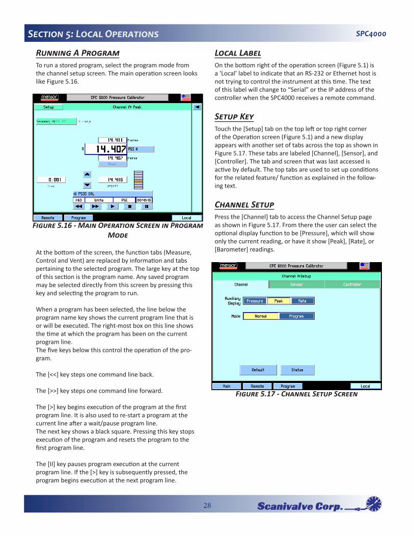
Running�A�ProgramTo run a stored program, select the program mode from the channel setup screen. The main operation screen looks like Figure 5.16.
At the bottom of the screen, the function tabs (Measure, Control and Vent) are replaced by information and tabs pertaining to the selected program. The large key at the top of this section is the program name. Any saved program may be selected directly from this screen by pressing this key and selecting the program to run.
When a program has been selected, the line below the program name key shows the current program line that is or will be executed. The right-most box on this line shows the time at which the program has been on the current program line.The five keys below this control the operation of the pro-gram.
The [<<] key steps one command line back.
The [>>] key steps one command line forward.
The [>] key begins execution of the program at the first program line. It is also used to re-start a program at the current line after a wait/pause program line.The next key shows a black square. Pressing this key stops execution of the program and resets the program to the first program line.
The [II] key pauses program execution at the current program line. If the [>] key is subsequently pressed, the program begins execution at the next program line.
Local�LabelOn the bottom right of the operation screen (Figure 5.1) is a ‘Local’ label to indicate that an RS-232 or Ethernet host is not trying to control the instrument at this time. The text of this label will change to “Serial” or the IP address of the controller when the SPC4000 receives a remote command.
Setup�KeyTouch the [Setup] tab on the top left or top right corner of the Operation screen (Figure 5.1) and a new display appears with another set of tabs across the top as shown in Figure 5.17. These tabs are labeled [Channel], [Sensor], and [Controller]. The tab and screen that was last accessed is active by default. The top tabs are used to set up conditions for the related feature/ function as explained in the follow-ing text.
Channel�SetupPress the [Channel] tab to access the Channel Setup page as shown in Figure 5.17. From there the user can select the optional display function to be [Pressure], which will show only the current reading, or have it show [Peak], [Rate], or [Barometer] readings.
Figure�5.16�-�Main�Operation�Screen�in�Program�Mode
Figure�5.17�-�Channel�Setup�Screen

29
SPC4000 Section 5: Local Operations
The content of the three active displays are:
[Pressure]: Shows no alternate readings on the screen, only the measured pressure reading.
[Peak]: Displays the highest and lowest pressure points since the last [Reset], or power up. Figure 5.2 shows an example of the Peak feature displayed in this window. [Rate]: Reports the rate at which the measured pressure is changing in units/second.
[Barometer]: If this optional feature was ordered with your SPC4000, press this key to display the atmospheric pressure reading.
[Normal] (mode selection): This mode will allow the user to command the instrument to individual setpoints manually or remotely.
[Program] (mode selection): This mode will allow the user to define and run user entered program sequences (Figure 5.12).
[Default]: Touch this key to immediately reset the instru-ment to the following conditions:
Autorange ON; a solenoid valve regulator module defaults to low overshoot mode (see “Sensor Setup”).Step value: Ignore if valid; Set to 1 if out of rangeSetpoint: Ignore if valid; Set to 0 if out of rangeRestart peak maximum and peak minimumSet sensor filter to NormalSet control rate to MaximumSet maximum allowable control point to match the highest maximum turndown in the instrument
Set minimum allowable control point equal the lowest minimum turndown in the instrumentSet the stable window to 0.003% FSSet the stable delay to 4 seconds.Any existing conditions not covered above will be unaf-fected.
[Status]: Touch this key to display all current channel infor-mation including: Model, Software Version, Serial Number, Range, and Units. See Figure 5.18.
Sensor�SetupTouch the [Sensor] tab and Figure 5.19 will appear.
Filter: The Filter is an electronic filter to smooth out the pressure readings. Because of the differences in resolution, more filtering may display a more stable reading for some pressure units. Select the best filter for the current units. [Off], [Low], [Normal], [High].
Resolution: The Resolution [value] key allows the user to enter the number of significant digits that will be displayed on the operate screen. See Figure 5.20.
[Calibrate] Setup key: Details for the [Calibrate] key are given in Section 7: Calibration.
Figure�5.18�-�Status�Screen Figure�5.19�-�Sensor�Setup�Screen

30
SPC4000Section 5: Local Operations
Controller�SetupThe controller setup screen (Figure 5.21 for the pump regulator or Figure 5.25 for the solenoid valve regulator) is used to set the control parameters for the selected pres-sure control channel.
The controller test screens are an interactive diagnostic dis-play used for troubleshooting the overall pneumatic system of the SPC4000. Proper use of these features are described in Section 6: Maintenance.
Pump�RegulatorControl Limits: The control limits cannot be set outside the maximum or minimum ranges of the transducers installed on the active channel. To change a limit touch either of the [Limit Value] keys and enter the new value.
Stable Limits: The stable limit is the percent of span of the active range that the current pressure can deviate from the setpoint and still display a stable flag.
To change the stable limit or stable delay press the appro-priate key. The pop-up number pad will show the upper and lower limits for the item being edited.
Stable Delay: The stable delay is the number of seconds that the instrument must remain within the stable window before the stable flag is displayed.
Rate: A rate (slewing speed) which best suits the user’s test requirements is selected here. The [Slow] rate will use internal pressure generation without the use of the rough-ing supply and exhaust valves. Use this mode if no external supply or exhaust pressures are applied to the selected
pressure control channel. The [Fast] rate utilizes the rough-ing supply and exhaust valves.
External Volume: If the autotune is turned on, the external volume of the controlled system is calculated automati-cally for optimum control performance. If the external volume is known, the user can press the external volume key and enter the volume. Subsequently, if [Autotune] is turned off, the control channel will not re-calculate the external volume on each control setpoint change which will decrease the control times.
Autotune: If the autotune key is turned on, the control channel automatically calculates the external system volume for optimum performance on each control setpoint change.
Figure�5.20�-�Resolution�Screen
Figure�5.21�-�Controller�Setup�-�Pump�Regulator
Figure�5.22�-�Stable�Limit�Screen

31
SPC4000 Section 5: Local Operations
[Test] key: is used to enter a test mode that gives the user individual control of all solenoids. This is further described in Section 6: Maintenance.
Solenoid�Valve�RegulatorControl Limits: The control limits cannot be set outside the maximum or minimum ranges of the transducers installed on the active channel. To change a limit touch either of the [Limit Value] keys and enter the new value.
Stable Limits: The stable limit is the percent of span of the active range that the instrument can deviate from the setpoint and still display a stable flag. To change the stable limit or stable delay press the appropriate key. The pop-up number pad will show the upper and lower limits for the item being edited.
Stable Delay: The stable delay is the number of seconds
that the instrument must remain within the stable window before the stable flag is displayed.
Rate: A rate (slewing speed) which best suits the user’s test requirements are selected here. The rates vary the pressure slew rate while driving to a pressure setpoint. The [Slow] rate will target approximately .1% of the highest installed range/second. The [Medium] rate will target approximately 1% of the highest installed range/second. The [Fast] rate will target approximately 10% of the highest installed range/second.
Variable rate allows the customer to enter the desired rate that the controller will approximate in the current units/second.
Low Overshoot check: If this is checked, the control chan-nel will minimize pressure overshoot when driving to a new control setpoint.
[Precision] key: If this key is selected, parameters are loaded into the active channel so that it will operate with minimum overshoot and maximum stability. This changes the control stable window to 0.003% of the active sensor turndown and the stable delay to 4 seconds.
High Speed] key: If this key is selected, parameters are loaded into the active channel so that it will operate in a high control speed mode. This changes the control stable window to 0.006% of the active sensor turndown and the stable delay to 1 second. It also changes the way the con-trolled pressure approaches the setpoint to minimize the time to stable.
Figure�5.23�-�Control�Limits�Screen
Figure�5.24�-�Stable�Delay�Screen
Figure�5.25�-�Controller�Setup�-�Solenoid�Valve�Regulator
32
SPC4000Section 5: Local Operations[Test] key: This key is used to enter a test mode that gives the user individual control of all solenoids. This is further described in Section 6: Maintenance.
[Tune] key: This key is used to tune the regulator. This is described further in Section 6: Maintenance.

33
SPC4000 Section 6: Maintenance
SECTION�6:�MAINTENANCEAny maintenance outside of the information provide in this section is not recommended by the customer. Contact Sca-nivalve customer support if further maintenance or support is required.
Troubleshooting�the�SPC4000�-�Pump�RegulatorThe SPC4000 has two Controller test screens; one is for the Pump Regulator (see Figure 6.1) and the other is for the Solenoid Valve Regulator (see Figure 6.4).
To get to the test screen press [Setup], [Controller], and [Test]. The pump regulator test screen allows control of the solenoid valves directly by the operator. Pressing the key labeled [Closed] or [Open] will toggle the associated solenoid between the open and closed states. As each key is pressed the key will change text and color, and the target solenoid will make an audible “click”. If a key changes color without the accompanying click it is an indication of a defective solenoid or a bad connection. Pressing the [+] or [-] key will actuate the pump and increase or decrease the system pressure respectively. The [speed] key allows adjustment of the relative rate at which the pump oper-ates to increase or decrease pressure. The [%] key allows an adjustment of the duty cycle of the supply and exhaust valves. The Primary and Secondary labels show the pres-sure sensed at the respective transducers. The Rate [psi/sec.] label indicated the rate of change of the system pressure. See Figure 6.2 for the pump regulator pneumatic module. See Figure 6.3 for the pneumatic schematic for the pump regulator.
CAUTION! The following test fea-ture is a powerful troubleshooting tool, but it incurs a dangerous potential for misdirecting high pressures. Study the pneumatic schematics (Figure 6.3) to under-stand the possible consequences of various pressure routings.
CAUTION! System pressure should not be drive above the range of the primary transducer. The valve isolat-ing the secondary transducer should be closed before the system pres-sure is driven above the range of the range of the secondary transducer.
Figure�6.1�-�Test�Screen,�Pump�Regulator
Figure�6.2�-�Pneumatic�Module,�Pump�Regulator

34
SPC4000Section 6: Maintenance
Figure�6.3�-�Pneumatic�Schematic�-�Pump�Regulator

35
SPC4000 Section 6: Maintenance
Troubleshooting�the�SPC4000�-�Solenoid�Valve�Regulator
The Solenoid Valve Regulator test screen (Figure 6.4) allows control of the solenoid valves directly by the operator. Pressing [Closed] or [Open] key will toggle the associ-ated solenoid between the open and closed states. As each key is pressed the key will change text and color, and the target solenoid will make an audible “click”. If a key changes color without the accompanying click it is an indication of a defective solenoid or a bad connection. The [+], [++], and [+++] represent the fine, medium and course regulator supply valves respectively. The [-], [--], [---] keys represent the fine, medium and course regulator exhaust valves respectively. Applying a continuous touch to any of these keys will open the respective regulator valve and increase or decrease the system pressure. The [%] key (top left) allows a collective adjustment of the duty cycle of the regulator valves to adjust the flow rate through the regula-tor. The Primary and Secondary labels show the pressure sensed at the respective transducers. The Rate [psi/sec.] label indicated the rate of change of the system pressure. See Figure 6.6 for the pneumatic schematic for the solenoid valve regulator.
CAUTION! The following test fea-ture is a powerful troubleshooting tool, but it incurs a dangerous potential for misdirecting high pressures. Study the pneumatic schematics (Figure 6.6) to under-stand the possible consequences of various pressure routings.
CAUTION! System pressure should not be drive above the range of the primary transducer. The valve isolat-ing the secondary transducer should be closed before the system pres-sure is driven above the range of the range of the secondary transducer.
Figure�6.5�-�Pneumatic�Module,�Solenoid�Valve�Regulator
Figure�6.4�-�Test�Screen,�Solenoid�Valve�Regulator

36
SPC4000Section 6: Maintenance
Figure�6.6�-�Pneumatic�Schematic�-�Solenoid�Valve�Regulator

37
SPC4000 Section 6: Maintenance
Tuning�a�Solenoid�Valve�Regulator
Tuning Modes:[Standby]: Seals all outside connections.[Measure]: Isolates the active sensor and measure/control port.[Control]: Controls to displayed setpoint in % F.S.[Vent]: Opens manifold to atmosphere.Setpoint = Desired pressure in % F.S.Reading = Measured pressure in % F.S.Supply = Supply fine bleed valve.Balance = Balance between supply and exhaust fine valves.Exhaust = Exhaust fine bleed valve.[SAVE]: Saves the supply and exhaust fine bleed valves to the regulator.Typical supply and exhaust values will be 3.00 to 6.00.
Tuning Procedure:1. Plug Measure/Control port.2. Connect supply pressure equal to 110% of the maxi-
mum range for that channel and a vacuum pump if necessary.
3. Press [Setup] [Controller] [Tune] on the channel you wish to tune.
4. Press the box to the right of the Setpoint and enter 50.00 and [OK].
5. |Push the [Control] button and watch the value in the box to the right of Reading climb towards the setpoint.
6. If the Reading stays below the Setpoint increase the Supply value by .1 until the setpoint is reached.
7. Again press the box to the right of Setpoint and enter 25.00 and [OK].
8. If the Reading stays above the Setpoint increase the Exhaust value by .1 until the setpoint is reached.
9. Return again to the Setpoint of 50 by repeating step 4.
10. Evaluate the way the reading reacts when approaching the setpoint and repeat steps 6 and 8 until the desired result is reached.
11. When you are satisfied with the performance of the regulator, press the [Save] button to store the changes you have made to the regulator. These values are stored in nonvolatile memory on the regulator and they will be saved through power cycles.
Transducer�Removal
1. VENT THE SYSTEM! Then turn off the power.2. Loosen the two captive screws on the front panel
(Figure 1.2), and swing the panel open.3. Unscrew the thumb screw holding in the transducer
(Figures 6.2 and 6.7).4. Apply a light inward pressure against the bottom of the
transducer case, just below the range label, while tilt-ing the case upward to clear the clamp plate and screw head.
5. Pull the transducer module outward, through the front opening.
NOTE: Always store loose transducers and PC boards in static protective bags or containers.Removing a transducer disengages the electrical and pneumatic connections and seals off the pressure on the pneumatic module. This permits the SPC4000 to be turned on with the supply pressure connected even with no trans-ducers installed.
Each control channel has pressure control limits. Typically, the pump regulator modules have a maximum limit of 15 psig and the solenoid valve regulator modules have limits
Figure�6.7�-�Tune�Screen,�Solenoid�Valve�Regulator
CAUTION: ESD PROTECTION REQUIRED. The proper use of grounded work surfaces and personal wrist straps are required when coming into contact with exposed circuits (printed cir-cuit boards) to prevent static discharge damage to sensitive electronic components.
CAUTION! There must be a trans-ducer installed in the “Primary Transducer” berth for the system to function properly. If the system is operated with the primary berth empty the results will be unpredict-able.

38
SPC4000Section 6: Maintenanceof 50-150 or 1500 psig. If a sensor is placed into a control channel where the sensor has a higher upper pressure range than the control module, the maximum control limit will be limited to the maximum range of the control module.
While any sensor can be installed in any control channel, the results may not always be optimum. It is not recom-mended to install a low pressure transducer in a high pressure channel. A high pressure transducer should not be installed in a low pressure channel.
Transducer�InstallationTo replace a transducer first make sure that it is going into the proper transducer berth in the pneumatic module. Each
berth is clearly marked on the pneumatic module baseplate (see Figure 1.6). The “PRIMARY TRANSDUCER” must be the transducer with the highest pressure range.
To install a transducer with the front panel already open:
1. Rest the transducer on the baseplate and the retention bar. The transducer will be tilted down slightly.
2. Slide the transducer inward until resistance is felt. Then apply enough pressure against the transducer for it to clear the clamp so that it clears the retention bar and is fully seated and level on the baseplate.
3. Tighten the thumb screw to secure the transducer.4. Swing the front panel closed and secure it by tightening
the two captive screws.
Pneumatic�Module�Removal
1. VENT THE SYSTEM! Then turn off the power.2. Remove top cover.3. Remove all external pressure connections.4. Remove the 6 slotted 2.5mm screws that fasten the
pneumatic module rear panel to the chassis.5. Inside the pneumatic module disconnect one 9-pin
D-sub connector at the regulator, and the two connec-tors on the power cable.
6. Slide the pneumatic module out through the rear and clear of the chassis.
NOTE: Pneumatic modules have EMI containment strips that may necessitate some force to remove modules.
Pneumatic�Module�InstallationTo install or replace the pneumatic module, simply reverse the steps taken for its removal.
CAUTION! When transducers are replaced and the unit is rebooted, the default parameters will be loaded. If you are using custom set-tings they must be reloaded after transducer installation.
CAUTION! Do not install a high pres-sure transducer into a low pressure SPC4000. It is acceptable to install a low pressure transducer in a high pressure instrument, but control stability will be degraded.
CAUTION: ESD PROTECTION REQUIRED. The proper use of grounded work surfaces and personal wrist straps are required when coming into contact with exposed circuits (printed cir-cuit boards) to prevent static discharge damage to sensitive electronic components.
CAUTION: ESD PROTECTION REQUIRED. The proper use of grounded work surfaces and personal wrist straps are required when coming into contact with exposed circuits (printed cir-cuit boards) to prevent static discharge damage to sensitive electronic components.

39
SPC4000 Section 6: Maintenance
Figure�6.8�-�Chassis�Interior,�Top�View

40
SPC4000Section 6: Maintenance
Figu
re�6.9�-�Ch
assis�Interior
,�Fro
nt�View
41
SPC4000 Section 6: Maintenance
SPCPLU�DiagnosticsFigure 6.10 depicts the internal pneumatic schematic of the SPCPLU. This can be used to diagnose and locate any pneumatic logic errors or pressure leaks.
The best technique for diagnosing problems with the SPCPLU is to use pressure generated by the SPC4000 cali-brator and cap off the pressure outputs (CAL OUT and REF OUT) from the SPCPLU. By systematically capping off and opening the various pressure outlets while working through the various pneumatic logic states of the SPCPLU one can determine where a leak is or determine if a solenoid is faulty.
The LED’s on the front panel of the SPCPLU (Figure 1.10) also serve as a useful diagnostic tool. Confirming the LED’s logic matches the expected logic confirms that the digi-tal out signals are being properly sent from the SPC4000 calibrator.
One of the most common causes of problems with the SPCPLU is due to insufficient solenoid supply pressure. For SPCPLU-1&-2, a minimum of 90psi is required, 120psi maximum. For SPCPLU-3&-4 60psi minimum is required, 70psi maximum.

42
SPC4000Section 6: Maintenance
Figure�6.10�-�SPCPLU�Pneum
atic�Schematic
43
SPC4000 Section 7: Calibration
SECTION�7:�CALIBRATIONGeneralThe SPC4000 automatically adjusts the pressure reading for the effects of temperature and non-linearity within the calibrated temperature range of 15-45°C. The process is referred to as dynamic compensation because each read-ing is so adjusted before it is output to the display or to a communication bus. Thus, a calibrated SPC4000 operated within its temperature band, and with proper zero and span adjustments, will provide accurate pressure measure-ments.
EnvironmentFor maximum accuracy, allow the SPC4000 to warm up for a minimum of 30 minutes in an ambient temperature within the compensated range prior to commencing a cali-bration. In addition the instrument should be at rest on a stable platform that is free of excessive vibration and shock.
Pressure�StandardsScanivalve recommends the use of appropriately accurate primary pressure standards when calibrating this instru-ment. Such standards should be sufficient so that when
the techniques of the ISO Guide to the Expression of Uncertainty in Measurement (GUM) are applied, the instru-ment meets its accuracy statements as required by ISO/IEC 17025:2005, or other applicable standards.
MediaThe recommended calibration medium is dry nitrogen or clean dry instrument air. A height variation between the standard and the SPC4000 can cause significant errors. See “Head Pressure Correction” for further information.
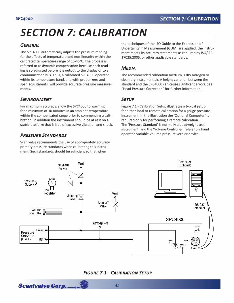
SetupFigure 7.1 - Calibration Setup illustrates a typical setup for either local or remote calibration for a gauge pressure instrument. In the illustration the ‘Optional Computer’ is required only for performing a remote calibration.The ‘Pressure Standard’ is normally a deadweight test instrument, and the ‘Volume Controller’ refers to a hand operated variable-volume pressure vernier device.
�Figure�7.1�-�Calibration�Setup

44
SPC4000Section 7: Calibration
PasswordAutozero does not require a password, however one is needed to change any date of calibration, Zero, Span, or to change the system password. The password installed at the factory was 1 2 3 4 5 6, but the user can change this as described below.
To Change the password:1. Press the [Calibrate] key to see the Calibration Data
screen similar to Figure 10.2. Notice the padlock.2. Touch the [Unlock] key to display the Enter Password
window as shown in Figure 10.3.
3. Enter the current password. As each number is pressed an ‘*’ appears in the ‘Password’ window. When com-pleted touch [OK] to unlock the calibration data screen.
4. The Calibration Data screen of Figure 10.4 is displayed. Use this screen to change the password to perform functions for 1 point calibration, 2 point calibration, restore factory cal, and head correction. Touch [Change Password] and the Change Password window appears as in Figure 10.5.
5. At the Change Password screen enter from one to six digits for a new password. As each number is pressed it appears in the Password window.
6. Before proceeding, review the displayed digits for accuracy. A mistake here could prevent future access to this screen. To make a correction use [CE] to backspace through the entries and then immediately re-enter the correct numbers.
Figure�10.2�-�Locked�Calibration�Data�Screen
Figure�10.3�-�‘Enter�Password’�Screen
Figure�10.4�-�Unlocked�Calibration�Data�Screen
Figure�10.5�-�‘Change�Password’�Screen
45
SPC4000 Section 7: Calibration
7. When satisfied that the new password is correct, and a written copy has been stored, press [OK] to com-plete the entry. The previous password is immediately replaced by the new one.
8. Confirm that the new password is valid by pressing [Main], then repeat steps 1 through 3 to return to the Calibration Data screen (Figure 10.4). If this screen can’t be accessed using either the old or the new password contact Scanivalve.
Restoring�Factory�CalibrationThe offset and slope values established for each turndown during the final factory calibration are stored in permanent memory within each transducer. These factory values can be restored at any time regardless of the number of sub-sequent calibrations. To restore the factory calibration to the active turndown, press [Restore Factory Cal] on the unlocked Data Entry screen seen in Figure 10.4. This will restore both the factory zero offset and slope calibration values to the active turndown. The [Restore Factory Cal] function can be repeated for each turndown as desired.
On-Site�CalibrationThe SPC4000 can contain one primary transducer and baro-metric reference and may have an additional, secondary transducer. Each transducer (except the Barometric Refer-ence Transducer) can have up to two separately calibrated ranges (two turndowns). Zero and span adjustments are available for each of these turndowns.
Linearity is preset at the factory and is not adjustable. One and two point calibrations are used to make a linear correction to the pressure readings using the formula: (uncorrected reading) X (slope) + offset. The one point cali-bration adjusts the offset, the two point calibration adjusts both the offset and the slope.
To perform an on-site calibration, follow the step-by-step procedure for calibrating a transducer.
SPC4000 PreparationEvacuate the pressure transducer(s) to a low pressure that will still maintain a viscous flow, typically 600 millitorr (0.0116 psi). At pressures lower than this the pressure at any particular point in the system is questionable. Allow from five to ten minutes for the target pressure to stabilize, then convert the millitorr reading to an equivalent instru-ment reading in the active measurement units. Table 3 in the Appendix lists millitorr conversion factors.
To begin a calibration, press the [Calibrate] tab and unlock the calibration screen as described in the previous section. Select the turndown to calibrate from the drop list and the units in which to perform the calibration on the unlocked calibration data screen.
Calibrate Setup KeyThe Calibration screen shown in Figure 10.6 is the first of several screens relating to the calibration functions. This screen allows the user to perform the following tasks:
1. Calibrate zero and span values on any turndown open of all installed sensors.
2. Establish a new Date of Calibration (DOC) for any turn-down;
3. Change the system password;4. Autozero all turndowns at one time.
Notice the padlock icon on the display. This signifies that the indicated values on the screen are not able to be modi-fied until the password has been entered.
CAUTION! The password is seldom used and is easily forgotten. After a change write down and save the new number. If the password is lost, contact Scanivalve.

46
SPC4000Section 7: Calibration[Unlock] Key: Touch [Unlock] (Figure 10.6) to move on to the password screen. This function is password protected. Details on this function are included in Section 7: Calibra-tion.
[Autozero] Key: Press this key to have the SPC4000 auto-matically re-zero all turndowns that can measure the vented pressure (Figure 10.8). This automatic function will:
1. Vent the system.2. Adjust the zero offset of each turndown that can mea-
sure the vented pressure so the turndown’s output is equal to zero.
NOTE: The autozero function re-zeros sensors without storing the zero offsets through power cycling.
Figure�10.6�-�Calibrate�Screen�(locked)
Figure�10.7�-�Calibrate�Screen�(unlocked)
Figure�10.8�-�Autozero�Key
Figure�10.9�-�Autozero�Screen
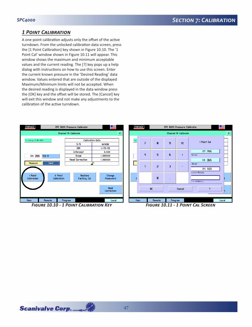
47
SPC4000 Section 7: Calibration
1�Point�CalibrationA one-point calibration adjusts only the offset of the active turndown. From the unlocked calibration data screen, press the [1 Point Calibration] key shown in Figure 10.10. The ‘1 Point Cal’ window shown in Figure 10.11 will appear. This window shows the maximum and minimum acceptable values and the current reading. The [?] key pops up a help dialog with instructions on how to use this screen. Enter the current known pressure in the ‘Desired Reading’ data window. Values entered that are outside of the displayed Maximum/Minimum limits will not be accepted. When the desired reading is displayed in the data window press the [OK] key and the offset will be stored. The [Cancel] key will exit this window and not make any adjustments to the calibration of the active turndown.
Figure�10.10�-�1�Point�Calibration�Key Figure�10.11�-�1�Point�Cal�Screen

48
SPC4000Section 7: Calibration
2�Point�CalibrationA two-point calibration adjusts both the offset and the slope of the active turndown. The low point must be within 20% of the minimum range of the active turndown and the high point must be within 20% of the maximum range of the active turndown. Insure that the head correction is adjusted properly, see ‘Head Pressure Correction.’ From the unlocked calibration data screen, press the [2 Point Cali-bration] key as shown in Figure 10.12. The ‘Low Point Cal’ window illustrated in Figure 10.13 will appear. This window shows the maximum and minimum acceptable values and the current reading. The [?] key pops up a help dialog with instructions on how to use this window. Enter the current known pressure in the ‘Desired Reading’ data window and press the [OK] key.
The ‘High Point Cal’ window illustrated in Figure 10.14 will appear. It’s function is identical to the ‘Low Point Cal’ window. Enter the new known pressure and press the [OK] key.
The [Cancel] key will exit either window and not make any adjustments to the calibration of the active turndown.
The ‘Date of Calibration’ window illustrated in Figure 10.15 will appear. Enter the date of calibration in a mm/dd/yyyy format exactly, including the ‘/’ separation marks. Press the [OK] key and the new data of calibration will be saved to the turndown.
Figure�10.15�-�Date�of�Calibration�Screen
Figure�10.12�-�2�Point�Calibration�Key
Figure�10.13�-�Low�Point�Cal�Screen
Figure�10.14�-�High�Point�Cal�Screen
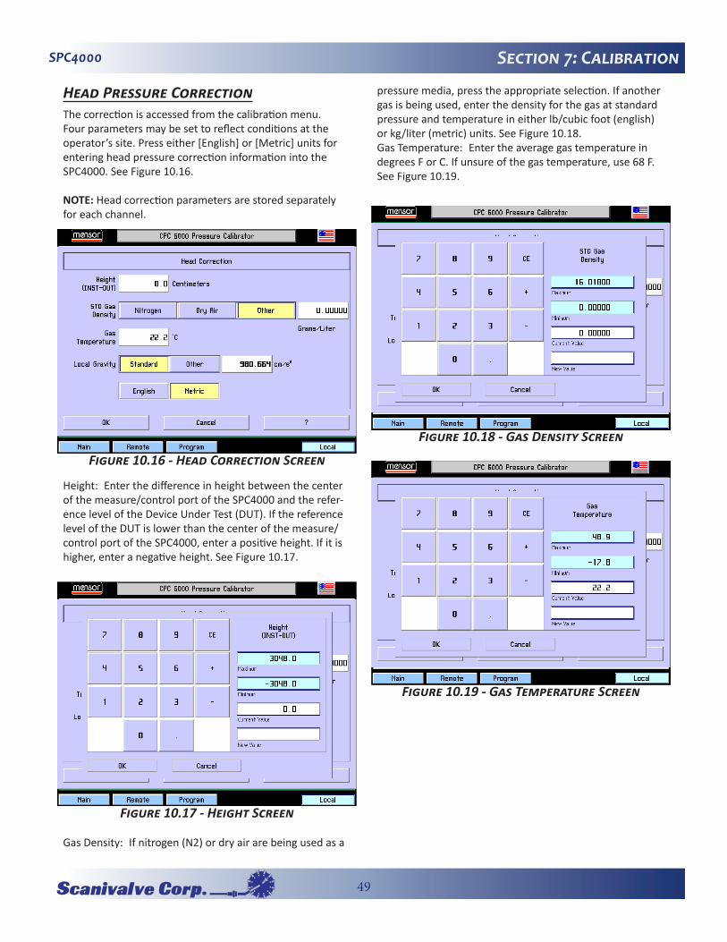
49
SPC4000 Section 7: Calibration
Head�Pressure�CorrectionThe correction is accessed from the calibration menu. Four parameters may be set to reflect conditions at the operator’s site. Press either [English] or [Metric] units for entering head pressure correction information into the SPC4000. See Figure 10.16.
NOTE: Head correction parameters are stored separately for each channel.
Height: Enter the difference in height between the center of the measure/control port of the SPC4000 and the refer-ence level of the Device Under Test (DUT). If the reference level of the DUT is lower than the center of the measure/control port of the SPC4000, enter a positive height. If it is higher, enter a negative height. See Figure 10.17.
Gas Density: If nitrogen (N2) or dry air are being used as a
pressure media, press the appropriate selection. If another gas is being used, enter the density for the gas at standard pressure and temperature in either lb/cubic foot (english) or kg/liter (metric) units. See Figure 10.18.Gas Temperature: Enter the average gas temperature in degrees F or C. If unsure of the gas temperature, use 68 F. See Figure 10.19.
Figure�10.16�-�Head�Correction�Screen
Figure�10.17�-�Height�Screen
Figure�10.18�-�Gas�Density�Screen
Figure�10.19�-�Gas�Temperature�Screen
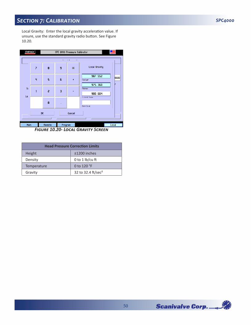
50
SPC4000Section 7: CalibrationLocal Gravity: Enter the local gravity acceleration value. If unsure, use the standard gravity radio button. See Figure 10.20.
Head Pressure Correction Limits
Height ±1200 inchesDensity 0 to 1 lb/cu ftTemperature 0 to 120 °FGravity 32 to 32.4 ft/sec²
Figure�10.20-�Local�Gravity�Screen
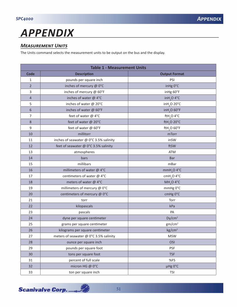
51
SPC4000 Appendix
APPENDIXMeasurement�UnitsThe Units command selects the measurement units to be output on the bus and the display.
Table 1 - Measurement UnitsCode Description Output Format
1 pounds per square inch PSI2 inches of mercury @ 0°C inHg 0°C3 inches of mercury @ 60°F inHg 60°F4 inches of water @ 4°C inH2O 4°C5 inches of water @ 20°C inH2O 20°C6 inches of water @ 60°F inH2O 60°F7 feet of water @ 4°C ftH2O 4°C8 feet of water @ 20°C ftH2O 20°C9 feet of water @ 60°F ftH2O 60°F
10 millitorr mTorr11 inches of seawater @ 0°C 3.5% salinity inSW12 feet of seawater @ 0°C 3.5% salinity ftSW13 atmospheres ATM14 bars Bar15 millibars mBar16 millimeters of water @ 4°C mmH2O 4°C17 centimeters of water @ 4°C cmH2O 4°C18 meters of water @ 4°C MH2O 4°C19 millimeters of mercury @ 0°C mmHg 0°C20 centimeters of mercury @ 0°C cmHg 0°C21 torr Torr22 kilopascals kPa23 pascals PA24 dyne per square centimeter Dy/cm2
25 grams per square centimeter gm/cm2
26 kilograms per square centimeter kg/cm2
27 meters of seawater @ 0°C 3.5% salinity MSW28 ounce per square inch OSI29 pounds per square foot PSF30 tons per square foot TSF31 percent of full scale %FS32 micron HG @ 0°C µHg 0°C33 ton per square inch TSI

52
SPC4000Appendix
Table 1 - Measurement UnitsCode Description Output Format
34 n/a n/a35 hectopascals hPa36 megapascals MPa37 millimeters of water @ 20°C mmH2O 20°C38 centimeter of water @ 20°C cmH2O 20°C39 meters of water @ 20°C MH2O 20°Cn/a User Units 1 User definedn/a User Units 2 User defined
Conversion�Factors,�PSIThe values listed in the column “To convert from PSI” are the values imbedded in the instrument program. The values listed under “To convert to PSI” are internally calculated approximations based on the imbedded values.
Table 2 - Conversion Factors, PSICode Pressure Unit To convert from PSI To convert to PSI
1 PSI 1 12 inHg 0°C 2.036020 0.49115443 inHg 60°F 2.041772 0.48977074 inH2O 4°C 27.68067 0.036126295 inH2O 20°C 27.72977 0.036062336 inH2O 60°F 27.70759 0.036091197 ftH2O 4°C 2.306726 0.43351498 ftH2O 20°C 2.310814 0.43274809 ftH2O 60°F 2.308966 0.4330943
10 mTorr 51715.08 0.0000193367211 inSW 0°C 3.5% salinity 26.92334 0.0371425012 ftSW 0°C 3.5% salinity 2.243611 0.44571013 ATM 0.06804596 14.6959514 Bar 0.06894757 14.5037715 mBar 68.94757 0.0145037716 mmH2O 4°C 703.0890 0.00142229517 cmH2O 4°C 70.30890 0.0142229518 MH2O 4°C 0.7030890 1.42229519 mmHg 0°C 51.71508 0.0193367220 cmHg 0°C 5.171508 0.193367221 Torr 51.71508 0.0193367222 kPa 6.894757 0.145037723 PA 6894.757 0.000145037724 Dy/cm2 68947.57 0.00001450377
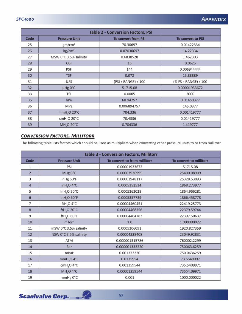
53
SPC4000 Appendix
Table 2 - Conversion Factors, PSICode Pressure Unit To convert from PSI To convert to PSI
25 gm/cm2 70.30697 0.0142233426 kg/cm2 0.07030697 14.2233427 MSW 0°C 3.5% salinity 0.6838528 1.46230328 OSI 16 0.062529 PSF 144 0.00694444430 TSF 0.072 13.8888931 %FS (PSI / RANGE) x 100 (% FS x RANGE) / 10032 µHg 0°C 51715.08 0.0000193367233 TSI 0.0005 200035 hPa 68.94757 0.0145037736 MPa 0.006894757 145.037737 mmH2O 20°C 704.336 0.00141977738 cmH2O 20°C 70.4336 0.0141977739 MH2O 20°C 0.704336 1.419777
Conversion�Factors,�MillitorrThe following table lists factors which should be used as multipliers when converting other pressure units to or from millitorr.
Table 3 - Conversion Factors, MillitorrCode Pressure Unit To convert to from millitorr To convert to millitorr
1 PSI 0.00001933672 51715.082 inHg 0°C 0.00003936995 25400.089093 inHg 60°F 0.00003948117 25328.530934 inH2O 4°C 0.0005352534 1868.2739775 inH2O 20°C 0.0005362028 1864.9662816 inH2O 60°F 0.0005357739 1866.4587787 ftH2O 4°C 0.00004460451 22419.257738 ftH2O 20°C 0.00004468356 22379.597449 ftH2O 60°F 0.00004464783 22397.50637
10 mTorr 1.0 1.00000002211 inSW 0°C 3.5% salinity 0.0005206091 1920.82735912 ftSW 0°C 3.5% salinity 0.00004338408 23049.9283113 ATM 0.000001315786 760002.229914 Bar 0.000001333220 750063.625915 mBar 0.001333220 750.063625916 mmH2O 4°C 0.0135954 73.554099717 cmH2O 4°C 0.001359544 735.540997118 MH2O 4°C 0.00001359544 73554.0997119 mmHg 0°C 0.001 1000.000022

54
SPC4000Appendix
Table 3 - Conversion Factors, MillitorrCode Pressure Unit To convert to from millitorr To convert to millitorr
20 cmHg 0°C 0.0001 10000.0002221 Torr 0.001 1000.00002222 kPa 0.0001333220 7500.63625923 PA 0.1333220 7.50063625924 Dy/cm2 1.333220 0.75006362625 gm/cm2 0.001359506 735.56116626 kg/cm2 0.000001359506 735561.16627 MSW 0°C 3.5% salinity 0.00001322347 75623.1166328 OSI 0.0003093875 3232.199229 PSF 0.002784488 359.13247730 TSF 0.000001392244 718265.057532 µHg 0°C 1.0 1.00000002233 TSI n/a n/a35 hPa 0.001333220 750.063625936 MPa 0.0000001333220 7500636.25937 mmH2O 20°C 0.01361955 73.4238811438 cmH2O 20°C 0.001361955 734.238811439 MH2O 20°C 0.00001361955 73423.88114
Conversion�Factors,�PascalThe following table lists factors which should be used as multipliers when converting other pressure units to or from Pascal.
Table 4 - Conversion Factors, PascalCode Pressure Unit To convert from Pascal To convert to Pascal
1 PSI 1.450377E-04 6.894757E+032 inHg 0°C 2.952997E-04 3.386390E+033 inHg 60°F 2.961339E-04 3.376850E+034 inH2O 4°C 4.014741E-03 2.490820E+025 inH2O 20°C 4.021862E-03 2.486410E+026 inH2O 60°F 4.018645E-03 2.488400E+027 ftH2O 4°C 3.345622E-04 2.988980E+038 ftH2O 20°C 3.351551E-04 2.983692E+039 ftH2O 60°F 3.348871E-04 2.986080E+03
10 mTorr 7.500636E+00 1.333220E-0111 inSW 0°C 3.5% sal 3.904899E-03 2.560885E+0212 ftSW 0°C 3.5% sal 3.254082E-04 3.073062E+0313 ATM 9.869230E-06 1.013250E+0514 Bar 1.00000E-05 1.00000E+0515 mBar 1.00000E-02 1.00000E+02
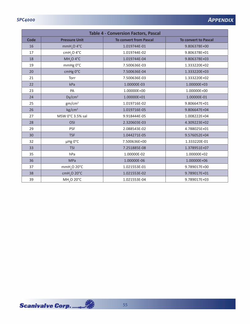
55
SPC4000 Appendix
Table 4 - Conversion Factors, PascalCode Pressure Unit To convert from Pascal To convert to Pascal
16 mmH2O 4°C 1.019744E-01 9.806378E+0017 cmH2O 4°C 1.019744E-02 9.806378E+0118 MH2O 4°C 1.019744E-04 9.806378E+0319 mmHg 0°C 7.500636E-03 1.333220E+0220 cmHg 0°C 7.500636E-04 1.333220E+0321 Torr 7.500636E-03 1.333220E+02
22 kPa 1.00000E-03 1.00000E+0323 PA 1.00000E+00 1.00000E+0024 Dy/cm2 1.00000E+01 1.00000E-0125 gm/cm2 1.019716E-02 9.806647E+0126 kg/cm2 1.019716E-05 9.806647E+0427 MSW 0°C 3.5% sal 9.918444E-05 1.008222E+0428 OSI 2.320603E-03 4.309223E+0229 PSF 2.088543E-02 4.788025E+0130 TSF 1.044271E-05 9.576052E+0432 µHg 0°C 7.500636E+00 1.333220E-0133 TSI 7.251885E-08 1.378951E+0735 hPa 1.00000E-02 1.00000E+0236 MPa 1.00000E-06 1.00000E+0637 mmH2O 20°C 1.021553E-01 9.789017E+0038 cmH2O 20°C 1.021553E-02 9.789017E+0139 MH2O 20°C 1.021553E-04 9.789017E+03
57
SPC4000
SPC4000�Operation�ManualRevision�BJuly,�2013