spatio-depth face recognition in l1 framework face recognition in l 1 framework a project report...
TRANSCRIPT

Spatio-Depth Face Recognition in l1
framework
A project report
submitted in partial fulfillment of the
requirements for the Degree of
Master of Technologyin
Computational Science
by
Sreekanth Raja
SUPERCOMPUTER EDUCATION AND RESEARCH CENTRE
INDIAN INSTITUTE OF SCIENCE
Bangalore - 560012
June 2012

Dedicated to my Parents and wife

Acknowledgements
It is a great pleasure for me to thank those who made this work possible. I thank
my project advisor Dr R Venkatesh Babu for his extreme support and guidance, which
has helped me complete this project work.I also thank all my teachers, whose teachings
sparked some lights of knowledge in me and helped me in some way or the other during
the tenure of this project. I thank my lab mates Rajendra, Priti, Sovan, Avinash and
Naresh who constantly helped and encouraged me in this work. Also I would extend all
my friends who actively participated and helped me during face-data collection, which
was the backbone of my project, as most of the results are shown with this data.
I thank the Director of Naval Physical Oceanographic Laboratory(DRDO), my senior
officers, who were willing to relieve me off my duties in spite of busy work schedules to
join IISc for this course. I also thank my parents and wife, who constantly supported me
throughout. Last but not the least, my whole hearted pranams to my Guruji.
iii

Abstract
Face recognition using Sparse representation has caught the attention of many com-
puter vision researchers across the world. In this project, the possibility of using Sparse
Representation based Classification (SRC) for facial depth images is explored. SRC is done
by minimizing the l1 norm of the coefficient vector x, subject to a linear constraint of the
form Ax = b. Face database of 49 subjects was created and the results are presented
on this database. The results are bench-marked with the following features: spatially
down-sampled image, Quantized depth images, contours of depth images and randomly
oriented faces. Subspace methods for face recognition have been well accepted for a long
time in face recognition community. In this study, an attempt is made to combine sub-
space methods and SRC framework. The use of eigenfaces, Fisherfaces and Laplacianfaces
in the dictionary of SRC is explored. The use of these basis vectors in l1 frame work gave
better performance compared to the conventional dimension reduction methods using
Principal Component Analysis (PCA), Linear Discriminant Analysis (LDA) and Locality
Preserving Projections (LPP). Also other dimension reduction techniques like Random
Projection(RP) and Optimal Random Projection for Sparse Representation based Clas-
sification (OPSRC) also gave encouraging results for depth images. A new projection
method for SRC has been proposed, which uses the ‘within class’ and ‘across class’ data
scatter matrices. Results show that the proposed method is computationally very effi-
cient compared to OPSRC, which is the optimum projection for SRC. The recognition
performance of the proposed approach is similar to OPSRC.
keywords: Sparse representation, Principal Component Analysis, Linear Discriminant
Analysis, Locality Preserving Projections, Random Projection, l1 minimization.
iv

Contents
Acknowledgements iii
Abstract iv
List of Figures vii
List of Tables ix
1 Introduction 1
2 Sparse Representation Based Classification 5
2.1 The Sparse Model . . . . . . . . . . . . . . . . . . . . . . . . . . . . . . . 5
2.2 Classification using Sparse Representation . . . . . . . . . . . . . . . . . . 7
2.3 Geometric Interpretation . . . . . . . . . . . . . . . . . . . . . . . . . . . . 7
3 Database Creation 9
3.1 Normalization . . . . . . . . . . . . . . . . . . . . . . . . . . . . . . . . . . 10
3.2 Calibration . . . . . . . . . . . . . . . . . . . . . . . . . . . . . . . . . . . 10
3.3 Face Extraction . . . . . . . . . . . . . . . . . . . . . . . . . . . . . . . . . 11
4 Feature Vectors 13
4.1 Introduction . . . . . . . . . . . . . . . . . . . . . . . . . . . . . . . . . . . 13
4.1.1 Reshaped Face Images . . . . . . . . . . . . . . . . . . . . . . . . . 13
4.1.2 Spectral features of geometric curves . . . . . . . . . . . . . . . . . 15
4.1.3 Quantized Depth Images . . . . . . . . . . . . . . . . . . . . . . . . 17
4.2 Face Recognioton on Tilted Faces . . . . . . . . . . . . . . . . . . . . . . . 18
5 SRC and Face Subspaces 21
5.1 Subspace Methods for Face Recognition . . . . . . . . . . . . . . . . . . . 22
5.1.1 Eigenface Method . . . . . . . . . . . . . . . . . . . . . . . . . . . 22
5.1.2 Fisherface Method . . . . . . . . . . . . . . . . . . . . . . . . . . . 23
5.1.3 Laplacianface Method . . . . . . . . . . . . . . . . . . . . . . . . . 24
5.1.4 Random Projection . . . . . . . . . . . . . . . . . . . . . . . . . . 24
5.1.5 Optimal Projection for SRC . . . . . . . . . . . . . . . . . . . . . . 25
5.1.6 A projection approach for SRC . . . . . . . . . . . . . . . . . . . . 26
v

vi Spatio-Depth Face Recognition in l1Framework
5.2 Results and Discussions . . . . . . . . . . . . . . . . . . . . . . . . . . . . 27
5.2.1 Eucledian Metric based Classification . . . . . . . . . . . . . . . . 27
5.2.2 SRC based classification . . . . . . . . . . . . . . . . . . . . . . . . 29
6 Conclusion 35
Bibliography 37

List of Figures
2.1 Geometry of sparse solution . . . . . . . . . . . . . . . . . . . . . . . . . . . 8
3.1 Database creation Process . . . . . . . . . . . . . . . . . . . . . . . . . . . . 9
3.2 (a) Before normalization (b) After normalization . . . . . . . . . . . . . . . . . 10
3.3 (a) Before Calibration (b) After Calibration . . . . . . . . . . . . . . . . . 11
3.4 (a) Detected face (b) Corresponding depth image . . . . . . . . . . . . . . . . 11
4.1 Inducing Illumination change in greyscale images . . . . . . . . . . . . . . 14
4.2 l1 vs Subspaces under illumination . . . . . . . . . . . . . . . . . . . . . . 15
4.3 Geometric contours on face: (a)Circular (b)Spiral (c)Ellipse . . . . . . . 16
4.4 Quantization at level 4,8 and 16 . . . . . . . . . . . . . . . . . . . . . . . . 17
4.5 Orthogonal rotation of faces (a)Straight Face (b) Oriented faces obtainedfrom orthogonal rotation of (a) . . . . . . . . . . . . . . . . . . . . . . . . 18
5.1 Euclidean Distance based classification for PCA, LDA and LPP (a)Texas Depth(b)
Texas Greyscale (c) VAL depth (d) VAL greyscale . . . . . . . . . . . . . . . . 28
5.2 Classification using PCA basis ,LDA basis and LPP basis in dictionary (a)Texas
Depth(b) Texas Greyscale (c) VAL depth (d) VAL greyscale . . . . . . . . . . . 30
5.3 Classification using Random Projection,OPSRC and proposed method for SRC
(a)Texas Depth(b) Texas Greyscale (c) VAL depth (d) VAL greyscale . . . . . . 32
5.4 Classification using Random Projection,OPSRC and proposed method forSRC Yale Database B . . . . . . . . . . . . . . . . . . . . . . . . . . . . . 33
vii


List of Tables
4.1 l1 vs l2 Classification . . . . . . . . . . . . . . . . . . . . . . . . . . . . . . . 13
4.2 Classification using l1 minimization in (%), averaged across all subjects . . . . . 14
4.3 Classification using Eigenface in (%), averaged across all subjects . . . . . . . . 15
4.4 Classification rate for combined(Depth and Grey scale) , averaged acrossall subjects . . . . . . . . . . . . . . . . . . . . . . . . . . . . . . . . . . . 16
4.5 Classification rate in percentage for Band limited Contours . . . . . . . . . . . 17
4.6 Classification rate in percentage of Depth Quantized image in l1 framework . . . 18
4.7 Classification of rotated images . . . . . . . . . . . . . . . . . . . . . . . . . . 19
5.1 Classification using Eigenface ,Fisherface and Laplacianface . . . . . . . . . . . 28
5.2 l1 Classification using PCA basis ,LDA basis and LPP basis in dictionary . . . . 31
5.3 Time Taken in seconds for calculating Projection Matrix . . . . . . . . . . . . 31
5.4 l1 Classification using Random Projection,OPSRC and proposed method for SRC
Yale Database B . . . . . . . . . . . . . . . . . . . . . . . . . . . . . . . . . 31
5.5 Classification using Random Projection,OPSRC and proposed method for SRC . 33
ix

Chapter 1
Introduction
Face recognition is one of the most inevitable parts of modern day biometric identification
systems, along with fingerprint identification, iris based recognition etc. It has got wide
spread applications in various military as well as civilian applications. There is a vast
plethora of research literature available on face recognition techniques [1][2].
Conventional face recognition systems use the RGB/gray scale images of faces for recog-
nition purpose. However with the advent of low cost 3D cameras, a lot more researchers
have started using the possibility of the third dimension in areas like face recognition,
human action recognitions, gait recognition etc. 3D Face recognition algorithms [3][4]
uses the depth information of the face, in addition to the grey scale intensity values.
The depth information provides additional features for recognition. Most of the 2D face
recognition algorithms rely on facial features like relative position of eyes, nose etc and
its shape, skin color, texture etc. On the other hand, in 3D face recognition, the data
capture information about the face like size of nose, depth of eye sockets etc. Unlike grey
scale or RGB images, depth information is invariant to luminous conditions, skin color
etc and is more robust.
This project work explores the possibility of using the depth information and spatial
greyscale values of face for recognition purpose in the l1 framework. There are various
features that can be extracted from depth images of human faces.
For this study, the kinect camera, which is a part of Microsoft Xbox360 gaming console
[5], with both RGB and depth sensor was used to create a database for 3D face recognition.
The depth sensor uses infra red trans-receiver to calculate the depth information. This
device gives both RGB and depth images. A face database with 49 subjects was created
for this experiment. This includes samples of 49 distinct faces under different expressions
and orientations. The depth and RGB frames were extracted from the frontal view videos
of each subject. The faces were extracted from each frame using Viola-Joness [6] face
1

2 Spatio-Depth Face Recognition in l1Framework
detector, and were used for training and testing. Face recognition was tried using l1
minimization framework, also called Sparse Representation based Classification (SRC).
With the advent of compressed sensing theory [7][8], sparse representation is being
successfully used for face recognition. These approaches have given encouraging results.
Theoretically the sparse representation [9] uses the l0 minimization to find the optimal so-
lution for the representation problem. But due to the NP hard nature of this optimization
problem, it is solved using an equivalent l1 minimization problem. This l1 minimization
algorithm is computationally more efficient and can be solved in polynomial time. An-
other advantage is that as the number of distinct classes for recognition increases, the
degree of sparsity also increases. However, there is slight difference between compressed
sensing and the sparse representation based classification suggested by Wright et al. [9].
In compressed sensing theory, the main aim is to recover a signal completely by sampling
at a sub Nyquist rate. On the other hand, in sparse representation based classification,
the sparsity structure of the signal representation is used to decode the identity of an
unknown signal.
Before the introduction of SRC, the most popular face recognition algorithms were
based on subspace methods. Eigenfaces [10], Fisherfaces [11] and Laplacianfaces [12] were
the most popular among them. In this project, an attempt is made to club subspace
method and SRC. Encouraging results are obtained in this study. The use of some sub-
space basis in the dictionary, instead of downsampled images has given better results. A
new discriminative projection for SRC is developed , which is low on computation, and
high on classification accuracy. The proposed algorithm has given encouraging results.
An attempt is also made to classify depth images of faces under varying pose. Face recog-
nition under varying angle and pose is a challenge in face recognition community. Here,
each face depth image is considered as a point cloud data. A 3-D orthogonal transform
is applied on the points to obtain different rotations of the face. Testing is done on both
actual rotated face data and synthetically rotated face images. Artificially rotated faces
give good classification performance. But for actual rotated faces, more rigorous models
needs to be developed.
There are various methods available in literature on face recognition. However, two of
the most common methods are using Principal Component Analysis(PCA)[10] and Linear
Discriminant Analysis(LDA)[11]. These are dimensionality reduction techniques, which
project the high dimension face data into a lower dimension face subspace. Final classi-
fication is done in this subspace. He et al. [12] suggested a laplacian face approach that
uses Locality Preserving Projection[13], which uses a graphical model that preserves the
local structure of the face data. Recently, Wright et al. [9] introduced the idea of face
representation using sparse representation, called Sparse Representation based Classifica-
tion(SRC). In this, the test sample is represented as a sparse linear combination of the
training images. The sparsity structure of the coefficients encodes the information about

Introduction 3
the identity of the test vector. Random Projections [14] [15] combines the idea of SRC
and subspace methods by projecting each face image into a random subspace. Lu and Yi
[16] came up with a supervised dimensionality reduction algorithm that gives a projection
that is supposed to be optimum for sparse representation based classification framework.


Chapter 2
Sparse Representation Based
Classification
2.1 The Sparse Model
In face recognition problems, each face is treated as an m× n matrix. There are various
methods of mapping it to a single vector. This is called feature vector extraction. One
of the most naive feature vector associated with an image is obtained by reshaping the
matrix into an mn × 1 vector. Assume there are k distinct classes of face data. Let
Ti = [ti,1, ti,2, · · · ti,li ] be the collection of feature vectors that represent the ith class. This
collection of features form the training set of the ith class. Each vector is called a training
vector. Assuming that there are sufficient number of training vectors for all the classes.
Given any new arbitrary sample vector of the ith class, it can be approximated by a linear
combination of the training vectors. Let y be the new vector, called the test vector, that
belong to the ith class. Then y can be expressed as
y =
li∑
j=1
ai,jti,j (2.1)
where, ai,j represents the weight (coefficient) of basis training vector ti,j .
Now the problem in face recognition is to find the class i to which the test vector y
actually belongs. For this we consider the concatenated dictionary matrix T
T = [T1T2.....Tk] (2.2)
The columns of the matrix T forms the Dictionary set. Now y can be written as
y = Tx (2.3)
5

6 Spatio-Depth Face Recognition in l1Framework
where x = [0, 0, ...ai,1, ai,2, ..ai,li , 0, 0....0]
We expect the solution vector x to encode the identity of the test vector y. Unlike the
Nearest Neighbor(NN) [17] classifier or the Nearest Subspace(NS) [18] classifier , SRC uses
the entire training set at a time to solve for x. The components of x are zeros except for
those associated with the ith class. This fact can be used to identify the class to which the
test vector belongs. So now the entire problem reduces to the most fundamental problem
of linear algebra - that of solving the system of equation Tx = y. In practice, (2.3) is an
under-determined system, since the total number of training vectors is much more than
the size of the vector. In order to avoid the anomaly of inconsistency of the system, we
assume that the matrix T has full rank. Thus the system (2.3) gives an infinite number of
solutions. Conventionally we go for that solution that has the minimal Euclidean norm.
This is the l2 solution for the problem:
x = arg min‖x‖2 subject to Tx = y (2.4)
This system can easily be solved using the pseudo inverse of T . However the solution
can be dense i.e, there can be a large number of non-zero entries corresponding to coef-
ficients of other classes and hence, may not be of much use in getting the identity of y.
So l2 solution is not suitable for this kind of problem. Since the test vector is represented
using the training vectors from the same class only, we are looking for a sparse solution,
i.e., a solution with minimal l0 norm. Though l0 norm do not follow the strict definition
of a norm, it is defined as the number of nonzero entries in a vector. The identity of y is
determined by the sparsity structure of x. Thus the problem is redefined as:
x = arg min‖x‖0 subject to Tx = y (2.5)
Theoretically, if the sparsity of the solution is less than mn/2, this is the most opti-
mum sparse solution which one can obtain [19]. But this is an NP hard problem [20].
However if the solution is sufficiently sparse, the solution is equal to that of the following
l1 minimization problem that can be solved in polynomial time [9, 21]:
x = arg min‖x‖1 subject to Tx = y
(2.6)
These can now be solved using standard techniques like linear programming, homptopy
[22] etc.

Sparse Representation Based Classification 7
2.2 Classification using Sparse Representation
The solution to (2.6) provides a sparse representation of the test vector y in terms of
the columns of the dictionary matrix T . In practice, (2.3) might be corrupted due to
measurement noise or occlusion. So the model can be modified as :
y = Tx0 + z (2.7)
where x0 is the sparse solution and z is due to the noise factor. So the new optimization
problem can be written as
x1 = arg min‖x‖1 subject to ‖Tx− y‖2 ≤∈
(2.8)
where ‖z‖2 < ǫ. For each class i define δi : RN → R
N as the characteristic function that
selects the coefficients of ith class only. i.e, δi(x) contains the coefficients of x corresponding
to the ith class only. Define ri(y) = ‖y−Tδi(x)‖2 as the reconstruction residual of y w.r.t
the ith class. Using this function, the test vector is reconstructed w.r.t each class. Finally
the identity of y is determined by the class that gives the minimal reconstruction residual.
The algorithm can be summarized as follows:
Algorithm 1 SRC Algorithm
1: Input: Test vector y and dictionary T with l2 normalized columns.2: Solve the l1 minimization problem:
x1 = argminx ‖x‖1 subject to ‖Tx− y‖2 ≤ ǫ3: Compute reconstruction residual ri = ‖y − Tδi(x1)‖2 for i = 1 . . . c.4: Output: Class of y = argmini ri(y)
2.3 Geometric Interpretation
Figure 2.1 gives a pictorial interpretation of sparse solution. The lp norm(p > 0) of a
vector x = (x1 · · ·xn) is defined as
‖x‖p = (n∑
j=1
|xi|p)1/p (2.9)
A word of caution about l0 norm. The l0 norm can be expressed as a limiting form of
lp norm for p > 0.
‖x‖0 = limp→0
‖x‖p = limp→0
{n∑
k=1
|x|p}1/p = #{i : xi 6= 0} (2.10)

8 Spatio-Depth Face Recognition in l1Framework
l0 norm satisfies triangle inequality,‖x + y‖0 ≤ ‖x‖0 + ‖y‖0 . However, fails to satisfy
homogeneity property. i.e,‖αx‖0 6= |α|‖x‖0
The unit balls in the lp norm, for different p-values appear as shown the figure 2.1. The
straight line represent the constraint of the form Tx = y. The minimum p−norm solution
can be obtained by expanding the lp balls, with center at the origin. It can be seen that
for p ≤ 1, the lp balls met the line on some points on the coordinate axis. Whereas, for
p > 1, the point of intersection is not on the axis. The points that lie on the co-ordinate
axis contains zeros in its components. In higher dimensions, this would mean that such
points have minimal l0 norm or in other words , is sparse.
Figure 2.1: Geometry of sparse solution

Chapter 3
Database Creation
A 3D face database of 49 people was created for this project. Most of the results presented
are on this database. These datas were recorded using Microsoft Kinect [5], a motion
sensing input device by Microsoft for the Xbox 360 video game console The Kinect sensor
provides both RGB and depth information of the image. Each frame of the video are of
resolution 640×480 pixels. The device used has two camera - a normal RGB and an infra
red camera, which provides the depth information.
Figure 3.1: Database creation Process
Since the depth and RGB frames are captured using two distinct sensors, the corre-
sponding depth and RGB (i.e., depth and RGB images corresponding to the same time
instant) image will have slightly misaligned field of view. Thus initially, a calibration
needs to be done before extracting the faces.Prior to calibration, all the RGB images are
converted to grey scale images. The database creation mainly consists of 3 steps (Figure
3.1): i) Normalization, ii) Calibration and iii) Face extraction.
9

10 Spatio-Depth Face Recognition in l1Framework
(a) (b)
Figure 3.2: (a) Before normalization (b) After normalization
3.1 Normalization
The depth sensor gives depth information in an 11 bit format. So the dynamic range
varies from 0 to 211 − 1 . But the region of interest is the face region. Thus the relative
variation of depth values on the face region would be too small. As a result it is possible
that certain features like the subtle variations in depths of nose, eye sockets etc may be
missed. In order to avoid this, the background is suppressed to zero and the total dynamic
range is reduced. In order to maintain uniformity in the normalization process, this map
is done with reference to the nose tip of the person. The new dynamic range is reduced
to an 8-bit value (0 to 255). This map improves the variation of depth value in the face,
as shown in Figure 3.2.
3.2 Calibration
Calibration of depth image is done by determining the affine transformation that models
the mismatch between the depth and RGB frames. It requires three distinct points of the
RGB image and the corresponding points of the depth image. This affine transformation,
caused due to a linear transformation, followed by a translation can be represented as
y = Ax + b, where y is the point on the depth image, corresponding to x in the RGB
image.
A set of 3 distinct points of the two images are used to find the affine transform matrix
A and the shift factor b. This requires some rectangular or checkerboard type patterns
with depth disparities so that corresponding points in the two images can be selected. The
matrix A known as the warping matrix. This warping matrix is then used for calibration
of all the depth images (Fig. 3.3).

Database Creation 11
(a) (b)
Figure 3.3: (a) Before Calibration (b) After Calibration
3.3 Face Extraction
Once the normalization and calibration of the depth image is done, the face region has
to be extracted from the image. Face detection was done using OpenCV implementation
of Viola et al. [6] on the greyscale images and the corresponding pixels of depth images
are extracted to obtain the depth images of face. The dimensions of these extracted face
were approximately 100× 100 pixels. Each of these face images were further reshaped to
a fixed lower resolutions for the final face recognition algorithm.
(a) (b)
Figure 3.4: (a) Detected face (b) Corresponding depth image


Chapter 4
Feature Vectors
4.1 Introduction
Face recognition can be classified into two types - appearance based and feature vector
based. Appearance based face recognition relies on the face image as such, or a reshaped
version of that. Even methods based on facial subspaces are considered as appearance
based face recognition. On the other hand, feature vector based face recognition relies on
certain features extracted from the face data. In this project, both appearance based
and feature vector based methods have been tried. A few new features have been tried
which gave promising results in the data. The most naive method is by resizing the face
image to a lower size and reshaping it into a column vector. One fundamental question
that would arise in mind is how l1 minimization framework would perform against l2?
Its known that l2 solution gives the least square solution of the under determined system
(2.3). Table 4.1 gives a comparison of l2 minimization based classification against l1 based
classification done on VAL greyscale data. The classification was based on reconstruction
error as explained in Algorithm 1. Its quite evident from the results that l2 minimization
is not suitable for classification.
4.1.1 Reshaped Face Images
Resized depth image is the naive feature used in appearance based face recognition. The
actual image is of the size 100×100 which , when reshaped becomes a vector of size 10000.
Table 4.1: l1 vs l2 Classification
Image Resolution 12× 10 20× 16 28× 24l1 94.3 94.9 95.2l2 12.2 14.6 17.1
13

14 Spatio-Depth Face Recognition in l1Framework
Figure 4.1: Inducing Illumination change in greyscale images
Table 4.2: Classification using l1 minimization in (%), averaged across all subjects
Number of training vectors used
Feature Resolution 20 15 10 5(in pixels)Grey Scale 28×24 98.16 98.27 97.86 97.45(Constant 20×16 98.27 98.06 97.76 97.96Illumination) 12×10 98.57 98.38 97.86 97.76
Grey Scale 28×24 82.96 82.25 80.61 80.51(Variable 20×16 76.94 76.12 75.82 73.78Illumination) 12×10 63.76 63.16 63.67 62.86
28×24 96.02 95.61 94.89 94.89Depth 20×16 95.71 96.02 95.20 94.79
12×10 96.53 96.22 94.28 94.08
Thus to reduce the vector size each face image is resized to 3 different resolutions viz,
28 × 24, 20 × 16 and 12 × 10. Each of these cases would then result in a feature vector
of size 672, 320, and 120 respectively. Then classification was done using l1 framework.
Illumination variation is a major challenge in greyscale face recognition. Depth image has
the advantage that it is invariant to change in illumination.
Table 4.2 shows the recognition rates for gray scale images, and depth images at dif-
ferent resolutions and training set sizes per subject using SRC. The figures represent
recognition rate in percentage, averaged across all subjects , and for 20 distinct test vec-
tors. Table 4.3 gives the performance of conventional eigenface method for depth and
greyscale image with and without illumination change. Illumination change was induced
artificially on greyscale images as shown in figure 4.1.
The dimension was reduced to 10 for PCA in constant illumination case. For variable
illumination dimension was reduced to 30. For both cases, i.e, variable and constant
illumination, SRC dominates eigenface approach.
The performance of l1 framework under varying illumination was also bench marked
against other subspace methods like LDA, LPP etc. Figure 4.2 shows these results. For

Feature Vectors 15
Table 4.3: Classification using Eigenface in (%), averaged across all subjects
Number of training vectors used
Feature Resolution 20 15 10 5(in pixels)Grey Scale 28×24 90.61 91.8 89.6 91.1(Constant 20×16 91.2 91.2 89 89.4Illumination) 12×10 94 93.4 92.8 91.7
Grey Scale 28×24 21.84 22.55 21.12 22.04(Variable 20×16 21.02 21.43 19.90 21.43Illumination) 12×10 18.06 18.16 17.24 18.67
28×24 93.6 91.51 93.1 88.5Depth 20×16 93.41 91.7 91.4 89
12×10 92.41 93.9 91.5 87.8
Figure 4.2: l1 vs Subspaces under illumination
all the subspaces the dimension was reduced to 30. The SRC framework has proven to be
quite robust to illumination variance.
The performance of greyscale and depth images combined together was studied. The
concatenated vectors corresponding to greyscale and depth images was used for training
and testing. Table 4.4 tabulates the performance. This gave a remarkable performance
of over 98% for most cases.
4.1.2 Spectral features of geometric curves
Band limited contours is another new feature introduced in this study. In this, geomeretic
curves like concentric circles, ellipse, spirals etc are considered on the face surface, with
the tip of the nose as point of reference. Tip of the nose is easy to detect in depth
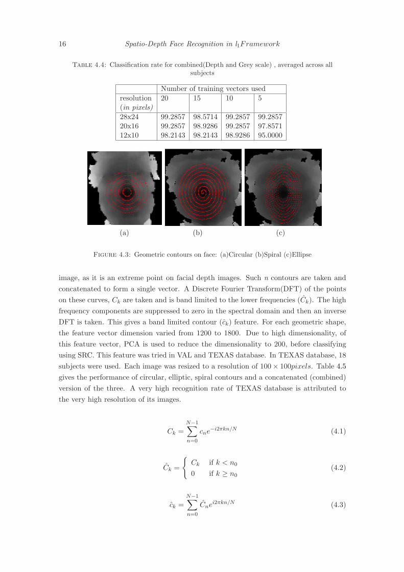
16 Spatio-Depth Face Recognition in l1Framework
Table 4.4: Classification rate for combined(Depth and Grey scale) , averaged across allsubjects
Number of training vectors used
resolution 20 15 10 5(in pixels)
28x24 99.2857 98.5714 99.2857 99.285720x16 99.2857 98.9286 99.2857 97.857112x10 98.2143 98.2143 98.9286 95.0000
(a) (b) (c)
Figure 4.3: Geometric contours on face: (a)Circular (b)Spiral (c)Ellipse
image, as it is an extreme point on facial depth images. Such n contours are taken and
concatenated to form a single vector. A Discrete Fourier Transform(DFT) of the points
on these curves, Ck are taken and is band limited to the lower frequencies (Ck). The high
frequency components are suppressed to zero in the spectral domain and then an inverse
DFT is taken. This gives a band limited contour (ck) feature. For each geometric shape,
the feature vector dimension varied from 1200 to 1800. Due to high dimensionality, of
this feature vector, PCA is used to reduce the dimensionality to 200, before classifying
using SRC. This feature was tried in VAL and TEXAS database. In TEXAS database, 18
subjects were used. Each image was resized to a resolution of 100× 100pixels. Table 4.5
gives the performance of circular, elliptic, spiral contours and a concatenated (combined)
version of the three. A very high recognition rate of TEXAS database is attributed to
the very high resolution of its images.
Ck =N−1∑
n=0
cne−i2πkn/N (4.1)
Ck =
{Ck if k < n0
0 if k ≥ n0
(4.2)
ck =N−1∑
n=0
Cnei2πkn/N (4.3)
Feature Vectors 17
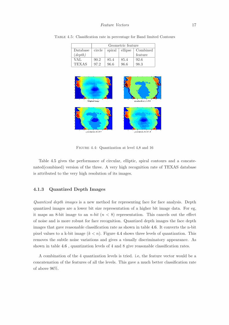
Table 4.5: Classification rate in percentage for Band limited Contours
Geometric featureDatabase circle spiral ellipse Combined(depth) featureVAL 90.2 85.4 85.4 92.6TEXAS 97.2 96.6 96.6 98.3
Figure 4.4: Quantization at level 4,8 and 16
Table 4.5 gives the performance of circular, elliptic, spiral contours and a concate-
nated(combined) version of the three. A very high recognition rate of TEXAS database
is attributed to the very high resolution of its images.
4.1.3 Quantized Depth Images
Quantized depth images is a new method for representing face for face analysis. Depth
quantized images are a lower bit size representation of a higher bit image data. For eg,
it maps an 8-bit image to an n-bit (n < 8) representation. This cancels out the effect
of noise and is more robust for face recognition. Quantized depth images the face depth
images that gave reasonable classification rate as shown in table 4.6. It converts the n-bit
pixel values to a k-bit image (k < n). Figure 4.4 shows three levels of quantization. This
removes the subtle noise variations and gives a visually discriminatory appearance. As
shown in table 4.6 , quantization levels of 4 and 8 give reasonable classification rates.
A combination of the 4 quantization levels is tried. i.e, the feature vector would be a
concatenation of the features of all the levels. This gave a much better classification rate
of above 96%.
18 Spatio-Depth Face Recognition in l1Framework
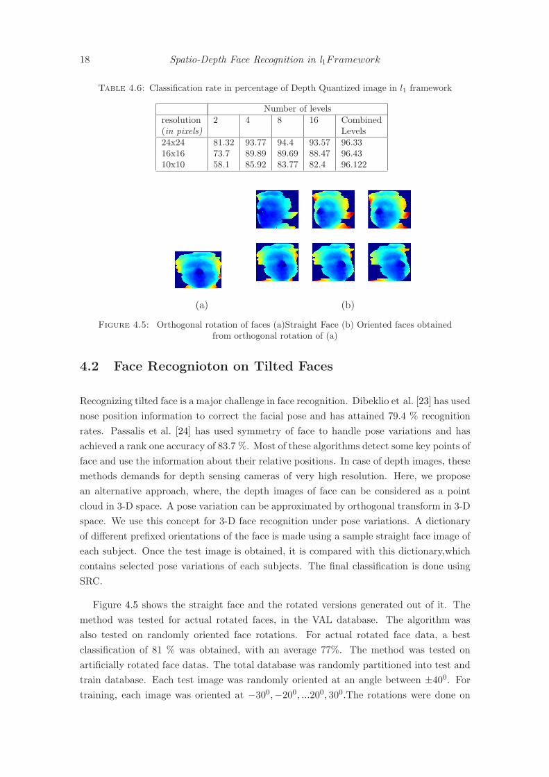
Table 4.6: Classification rate in percentage of Depth Quantized image in l1 framework
Number of levelsresolution 2 4 8 16 Combined(in pixels) Levels24x24 81.32 93.77 94.4 93.57 96.3316x16 73.7 89.89 89.69 88.47 96.4310x10 58.1 85.92 83.77 82.4 96.122
(a) (b)
Figure 4.5: Orthogonal rotation of faces (a)Straight Face (b) Oriented faces obtainedfrom orthogonal rotation of (a)
4.2 Face Recognioton on Tilted Faces
Recognizing tilted face is a major challenge in face recognition. Dibeklio et al. [23] has used
nose position information to correct the facial pose and has attained 79.4 % recognition
rates. Passalis et al. [24] has used symmetry of face to handle pose variations and has
achieved a rank one accuracy of 83.7 %. Most of these algorithms detect some key points of
face and use the information about their relative positions. In case of depth images, these
methods demands for depth sensing cameras of very high resolution. Here, we propose
an alternative approach, where, the depth images of face can be considered as a point
cloud in 3-D space. A pose variation can be approximated by orthogonal transform in 3-D
space. We use this concept for 3-D face recognition under pose variations. A dictionary
of different prefixed orientations of the face is made using a sample straight face image of
each subject. Once the test image is obtained, it is compared with this dictionary,which
contains selected pose variations of each subjects. The final classification is done using
SRC.
Figure 4.5 shows the straight face and the rotated versions generated out of it. The
method was tested for actual rotated faces, in the VAL database. The algorithm was
also tested on randomly oriented face rotations. For actual rotated face data, a best
classification of 81 % was obtained, with an average 77%. The method was tested on
artificially rotated face datas. The total database was randomly partitioned into test and
train database. Each test image was randomly oriented at an angle between ±400. For
training, each image was oriented at −300,−200, ...200, 300.The rotations were done on

Feature Vectors 19
Table 4.7: Classification of rotated images
Number of images/subject in DictionaryDatabase 1 2 3 4 5TEXAS Depth 90.3 - - - -
VAL Depth 80.4 87.8 91.9 94.6 94.8
X-Z plane with Y axis as the principal axis. These seven orientations were generated
for each training image. These were used in the dictionary for SRC. Table 4.7 gives
the classification percentage for synthetically rotated test image for VAL and TEXAS
depth database. For TEXAS database, all 103 distinct subjects were tested. Due to non
availability of sufficient test subjects, the results of only one test image per subject is
presented.


Chapter 5
SRC and Face Subspaces
There is a vast collection of face recognition methods available in literature [25] [1]. How-
ever, among them, subspace based face recognition methods[26] have achieved lot of sig-
nificance. Face subspace methods are considered to be appearance based methods. In
appearance based methods, each face image is represented as an m × n matrix, which
is reshaped into an mn dimension vector. However these mn dimension spaces are too
cumbersome to handle. The most common way to handle this curse of dimensionality
is to reduce the dimension to a level which can be comfortably handled. This technique
is called dimensionality reduction techniques. Principal Component Analysis [10], Lin-
ear Discriminant Analysis [11] and Locality Preserving Projections [12] are the most well
accepted dimension reduction techniques in face recognition.
In this study, we look at some dimensionality reduction techniques which is suitable
for Sparse Representation based Classification(SRC). Random projections [14] [15] is one
of the well accepted methods of SRC. Qiao et al [27] devised an unsupervised Spar-
sity Preserving Projection(SPP). Sparse Representation steered Discriminatory Projec-
tion(SRCDP) is another dimensionality reduction method proposed by Yang and Chu
[28]. In this chapter, we develop an new dimension reduction technique that is suitable
for SRC and is computationally much efficient. Can-Yi and De-Shuang [16] came up with
an optimal projection for SRC(OPSRC). This is a supervised dimensionality reduction
technique. The classification criterion for SRC is based on the reconstruction error cor-
responding to each class. The identity of a test image is the one that gives the minimum
reconstruction residual. The projection matrix for OPSRC is obtained by minimizing
the within class reconstruction error and simultaneously maximizing the between class
reconstruction error.
OPSRC is heavy on its computational complexity. For each vector in the dictionary,
it computes a within class and between class reconstruction error. For a dictionary of
size M × N , a single l1 minimization costs O(M2N3/2) computations. During training,
21

22 Spatio-Depth Face Recognition in l1Framework
the l1 minimization problem has to be solved as many times the number of columns in
the dictionary. A method that requires minimal computation, at the same time that
gives comparable discrimination as that of OPSRC is deviced. Our approach minimizes a
linear objective function that minimizes the within class scatter of the data, at the same
time , maximizes the between class scatter. Unlike LDA, which uses the same principle,
we use a different objective function compared to that of LDA. The time complexity is
also reduced by half in this new method.This method has a computational complexity of
O(M3), where M < N is the dimension of test vector. Results are presented to illustrate
the performance of the proposed method. First, a brief description of a few dimension
reduction techniques is presented.
5.1 Subspace Methods for Face Recognition
In subspace methods, the M(= mn) dimension face vector is mapped to a lower dimension
subspace. The final classification is done on this reduced dimension subspace. In each of
the subspace methods discussed below, a projection matrix P ∈ RM×d(d ≪ M) , is found
, which maps the M dimension vector x to a lower dimension vector y i.e, P : RM → Rd
y = P Tx (5.1)
where, x ∈ RM is the image vector and y ∈ R
d is its lower dimension representation in
the corresponding face subspace.
5.1.1 Eigenface Method
Eigenface method [10] is one the most popular subspace methods in face recognition.
Suppose we have the vectors x1 . . . xN xi ∈ RM . PCA finds a projection matrix P such
that yi = P Txi where P ∈ RM×d and yi ∈ R
d. This is done by maximizing the objective
function:
argmaxp
pTSp. subject to pT p = 1 (5.2)
where S is the covariance matrix of the entire training dataset.
S =1
N
N∑
i=1
(xi − x)(xi − x)T (5.3)
The solution for this is given by the eigenvectors {p1 . . . pd} corresponding to the d dom-
inant eigenvalues of S. The matrix P = [p1 . . . pd] projects each xi to the space spanned
by p1 . . . pd. These basis vectors are orthogonal and captures maximum variations in the
SRC and Face Subspaces 23
data. The eigenvectors{p1 . . . pd} are called the eigenfaces. Once the projection matrix
is obtained, the test and train image vectors are projected on to the reduced eigenspace.
The final classification is done by finding the Euclidean distance between the reduced test
and train vectors. The test image is classified as the one that gives minimum distance.
5.1.2 Fisherface Method
Fisherface method is yet another dimension reduction method, which projects the high
dimension face image to a lower dimension subspace for classification. This is based on
a method called Linear Discriminant Analysis(LDA), which projects the images into a
space which is highly discriminative by nature. Unlike PCA, here the objective function
is to maximize the objective function :
argmaxp
pTSbp
pTSwp(5.4)
where
Sb =
c∑
i=1
ni(x(i) − x)(x(i) − x)T (5.5)
Sw =c∑
i=1
(
ni∑
j=1
(x(i)j − x(i))(x
(i)j − x(i))T ) (5.6)
x(i) is the mean of the ith class, x(i)j is the jth sample of the ith class. x is the global
mean of the entire dataset, c is the number of distinct classes and ni is the number of
training images in the ith class. Sw is the within class scatter matrix and Sb is the between
class scatter matrix. The solution to this optimization problem are the eigen vectors
corresponding to the dominant eigen vectors of the generalized eigen value problem:
Sbp = λSwp (5.7)
The matrix Sw is always singular. So usually, a PCA is done on the data to reduce its
dimension so that you get c− 1 distinct eigenvectors. The matrix P = [p1 . . . pd] projects
each xi to the space spanned by the eigenvectors corresponding to the top d eigen vectors
of the above eigenvalue problem. The eigenvectors {p1 . . . pd} are called the fisherfaces.
Once the projection matrix is obtained, the test and train image vectors are projected
on to the reduced eigenspace. The final classification is done by finding the Euclidean
distance between the reduced test and train vectors. The test image is classified as the
one that gives minimum distance.Since the procedure involves solution of a generalized

24 Spatio-Depth Face Recognition in l1Framework
eigenvalue problem(5.7), its complexity is O(M3). Since it is a generalized eigenvalue
problem, the time complexity is more compares to eigenfaces.
5.1.3 Laplacianface Method
In this method, the face manifold structure is preserved by a nearest neighbor graph model,
which preserves the local structure of the image space. A face subspace is obtained by
projecting using Locality Preserving Projection[13]. The basis vectors that characterize
this projection are called the laplacianfaces. The objective function in this case is as
follows:
min∑
i,j
(yi − yj)2Sij (5.8)
where yi is the one dimensional representation of xi and S is a similarity matrix, which
characterizes the locality structure in the data set. One possibility of defining S is the
following heat-kernel function:
Sij =
{exp(−‖xi − xj‖
2/t) if x < 0
0 otherwise(5.9)
He et al. [12] have proved that the solution to this optimization problem is the solution
of the generalized eigenvalue problem
XLXT p = λXDXT p (5.10)
where D is a diagonal matrix whose ith diagonal entry is the ith row (or column) sum
of S, and L = D − S is the laplacian matrix. The solutions are the eigenvectors p1 . . . pd
corresponding to the least d eigenvalues of the above problem. The matrix P = [p1 . . . pd] is
the projection matrix for LPP. As in the case of Eigenface and Fisherface methods, the test
and train image vectors are projected on to the reduced space spanned by the rows of P .
The final classification is done by finding the Euclidean distance between the reduced test
and train vectors. The test image is classified as the one that gives minimum distance. As
with fisherfaces, Since the procedure involves solution of a generalized eigenvalue problem,
its complexity is O(M3). Since it is a generalized eigenvalue problem, the time complexity
is more compares to eigenfaces.
5.1.4 Random Projection
In random projection, the high dimensional face data is projected on to a lower dimen-
sional random subspace. A theorem due by Johnson and Lindenstrauss[29] states that

SRC and Face Subspaces 25
for any set of points of size n in Rp, there exist a linear transformation of the data into
Rq, where q ≥ O(ǫ−2log(n)) that preserves distance up to a factor of 1± ǫ. It is compu-
tationally superior to PCA, LDA and LPP. Forming a random matrix of size d×M and
projecting N vectors of dimension M to a lower dimension d takes only O(MN) compu-
tations. A condition on the matrix T that gaurentees a unique solution of (2.6) is called
the restricted isometery property(RIP):
(1− δ)‖x‖2 ≤ ‖Tx‖2 ≤ (1 + δ)‖x‖2 (5.11)
where δ is a small constant. In general, it is difficult to find deterministic matrices that
satisfy this property. However, matrices with i.i.d Gaussian columns, Bernoulli matrices
etc have been proven to satisfy RIP with a very high probability[30]. So in this method,
each face is projected on to a random subspace and this representation is used in the SRC
framework.
5.1.5 Optimal Projection for SRC
In all the previous three methods discussed, the classification was based on Euclidean
metric. Optimal Projection for Sparse Representation based Classification(OPSRC)[16]
is a supervised dimension reduction method designed for classification in the l1 framework.
OPSRC gives a discriminative projection, such that SRC attains optimum performance
in the transformed low-dimensional space.
Let P ∈ RM×d be the optimized projection where M is the actual dimension of the
image space and d ≪ M is the dimension of the reduced space. Let xij denote the jth
element of the ith class and let yij be its corresponding lower dimension representation.
So if X = [x11 . . . xcnc] and Y = [y11 . . . ycnc
], where c is the number of distinct classes
and ni is the number of training vectors in the ith class. Then Y = P TX. For each
yij , let αij be the coefficients of expressing yij as a sparse linear combination of all other
columns of Y , excluding yij . Let δi(ij) denote the vector whose only nonzero entries are
the entries in αij , corresponding to the ith class. Then the within class and between class
reconstruction residual matrices are defined as follows , respectively:
Rw =1
N
c∑
i=1
ni∑
j=1
(yij − Y δi(αij))(yij − Y δi(αij))T (5.12)
Rb =1
N(c− 1)
c∑
i=1
ni∑
j=1
∑
l 6=i
(yij − Y δl(αij))(yij − Y δl(αij))T (5.13)
Where N is the total number of training samples. In order to reduce the within class
reconstruction residual and to maximize the between class reconstruction residual, the

26 Spatio-Depth Face Recognition in l1Framework
following objective function is maximized:
J(P ) = tr(βRb − Rw) (5.14)
where, β is a weighting parameter. Since Y = P TX, we have Rw = P TRWP and
Rb = P TRbP . where,
Rw =1
N
c∑
i=1
ni∑
j=1
(xij −Xδi(αij))(xij −Xδi(αij))T (5.15)
Rb =1
N(c− 1)
c∑
i=1
ni∑
j=1
∑
l 6=i
(xij −Xδl(αij))(xij −Xδl(αij))T (5.16)
The new objective function now becomes
J(P ) = tr(P T (βRb −Rw)P ) (5.17)
The anomaly of degenerate solution is avoided by putting the constraint of pTi pi = 1.
The solution of this optimization problem are the eigen vectors corresponding to the
largest d eigenvectors of the matrix βRb − Rw. The final classification is done by doing
SRC on the reduced dimension space. The worst case complexity of this algorithm is
O(N2M3).
5.1.6 A projection approach for SRC
The computation of the optimal projection in OPSRC is computationally very much
demanding. For each column of the dictionary matrix, a set of sparse coefficients needs to
be computed. This drastically increases the computation involved in finding the projection
matrix. Here a new subspace projection is suggested, which is much more computationally
efficient and gives comparative performance to that of OPSRC. We define a linear function,
similar to that in OPSRC, except that instead of reconstruction residuals, we use the
scatter matrix defined in LDA. The objective function is:
argminp
pT (αSb − βSw)p; α, β > 0 (5.18)
subject to pT p = 1
where, α, β are weighting parameters and Sb and Sw are the between class and within class
scatter matrix as defined in (5.5) and (5.6). To solve this, we define Lagrange multiplier
as follows:
L(p, λ) = pT (αSb − βSw)p+ λ(1− pT p) (5.19)

SRC and Face Subspaces 27
Equating the partial derivative of L(p, λ) w.r.t p to zero, we get:∂L∂p = 2(αSb − βSw)p− 2λp = 0
⇒ (αSb − βSw)p = λp
Thus the solution are the eigenvectors corresponding to the leading d eigenvectors
{p1 . . . pd} of the matrix (αSb − βSw). Thus P = [p1 . . . pd] is the required projection.
It can be seen that there is only one simple eigenvalue problem involved. Solution of
LDA includes solution of generalized eigenvalue problem, which involves twice the com-
putation as that of this. The results presented in the next section shows that LDSRC
achieves comparable performance, compared to that of OPSRC, with significant reduction
in computation. This method has a worst case complexity of O(M3)
5.2 Results and Discussions
Various results involving SRC and eucledian distance based classification are presented in
this section. The results are demonstrated on 2 databases - the TEXAS 3D database [24]
[31] and the data collected in our lab, which we call the VAL database(Video Analytics
Lab database). For completion sake, the results are demonstrated not only on the depth
images, but also on the corresponding greyscale counterpart. Though TEXAS database
has images of 118 distinct subjects, we have used only 18 subjects among them for our
experiments. This is because, out of these 118 subjects, only 18 subjects have got sufficient
number of distinct samples. Most of them has got only a maximum of two samples per
subject, which is not sufficient for our experiments. For all the databases, the database
was randomly partitioned into test and train datas. For training, 5 sample images per
subjects were used for constructing the projection matrix. The number of dictionary
samples per subject also was fixed as 5. Test images are randomly selected over multiple
iterations and the average classification percentage is calculated. In PCA, LDA and LPP,
the final classification is based on eucledian metric. Whereas for random projections,
OPSRC and the proposed method, sparse representation based classification is used.
5.2.1 Eucledian Metric based Classification
He et al. [12] have shown that LPP gives better classification compared to LDA and
PCA. However, for very small dimensions, LDA has better discrimination than PCA and
LPP. In both the database used in this study, since there are not much variation, all the 3
methods, viz. LPP, PCA and LDA gave reasonably high classification even at a reduced
dimension of 10. This is justified by the reduced variability for each class in each dataset.
Table 5.1 gives the reduced dimension against classification for 4 sets of datas, namely
depth and greyscale datas of TEXAS and VAL database. Figure 5.1 plots the same.

28 Spatio-Depth Face Recognition in l1Framework
(a) (b)
(c) (d)
Figure 5.1: Euclidean Distance based classification for PCA, LDA and LPP (a)TexasDepth(b) Texas Greyscale (c) VAL depth (d) VAL greyscale
Table 5.1: Classification using Eigenface ,Fisherface and Laplacianface
Reduced Dimension
Database Subspace Method 4 6 8 10
TEXAS Eigenface 88.3 87.3 90.4 92.9(Depth) Fishercace 93.4 95.6 95.7 94.6
Laplacianface 87.4 92.7 93.3 93.9
TEXAS Eigenface 79.1 87.9 90.4 94.7(Greyscale) Fisherface 94.8 100 100 100
Laplacianface 85.2 94.9 97.4 97
Eigenface 91.7 93.3 93.7 94.9VAL Fisherface 92.3 94.2 94.6 94.6(Depth) Laplacianface 91.5 92.8 93.9 94.2
Eigenface 91.2 92.4 92.1 92.5VAL Fisherface 95.3 95.1 94.5 95.1(Greyscale) Laplacianface 90.9 93.6 93.8 94.2

SRC and Face Subspaces 29
For all the four datasets, it can be seen that classification percentage is consistently
above 90% for dimensions greater than 5. In all the cases, LDA performs better at this
level of dimension reduction. However, LPP would be giving better classification if the
reduced dimension is increased. TEXAS database gives better classification compared to
VAL database because of its high accuracy. Also, the fact that only 18 subjects are used
in classification for TEXAS database enhances its accuracy
5.2.2 SRC based classification
The performance of conventional dimension reduction method on depth images has shown
notable performance. Now a new scheme is tried , where the the subspace methods and
SRC are clubbed together. In conventional subspace methods, the test and train image
vectors are projected on to a lower dimension space and the low dimensional representation
is used for classification. Here, in this approach, initially all the test and train samples
are down sampled to a lower dimension. Let X = [x11 . . . xcnc] be the downsampled image
vectors and let D = [d11 . . . dcnc] be the dictionary elements corresponding to the training
image vectors, where dij is the jth sample of the ith class. Let pj denote the j
th dominant
subspace basis. By dominant subspace basis, we mean the eigenvector corresponding to
the dominant eigenvalue, as explained in the previous section. Essentially, p′js are the
eigenfaces, fisherfaces and laplacianfaces for PCA, LDA and LPP respectively. Then we
define dij as follows: dij = x(i) + pj where x(i) is the class mean of the ith class. Once
the dictionary is formed, for any downsampled test vector y, we solve the following l1
minimization problem and obtain the sparse solution α.
argminα
‖α‖1 subject to‖y −Dα‖2 ≤ ǫ (5.20)
Using the sparse coefficients α, we classify y, as described in Chapter 2. Table 5.2
compares the performance of this method using PCA, LDA, LPP and the conventional
downsampled version illustrated in Chapter 3. The average classification is compared
against the number of vectors per subject in the dictionary. The images are down sampled
to a resolution of 12× 12 pixels.
In all the datasets, simple downsampled feature dominates the classification perfor-
mance. However, among subspace basis used in dictionary, laplacian basis seems to show
better classification.
The performance of the newly proposed projection for SRC was compared with OP-
SRC and random projection. It was found that the proposed projection method gave
comparable performance with that of OPSRC. In OPSRC, the l1 minimization in done
O(N2) times, where N is the column size of the dictionary. This increased the compu-
tational complexity of OPSRC by an order of 2. As far as LDA is concerned, it requires

30 Spatio-Depth Face Recognition in l1Framework
(a) (b)
(c) (d)
Figure 5.2: Classification using PCA basis ,LDA basis and LPP basis in dictionary(a)Texas Depth(b) Texas Greyscale (c) VAL depth (d) VAL greyscale
solution of the generalized eigenvalue problem, in equation 5.7. Its complexity is O(N3).
Even though the proposed method has the same complexity as that of LDA, its time
complexity is less since it requires to solve only a simple eigenvalue problem. Table 5.3
compares the time taken to calculate a projection matrix of size 1024 × 10 for different
dictionary/data size. The proposed algorithm performs better as far as time complexity
is considered.
Table 5.5 and figure 5.3 shows classification percentage against reduced dimension.
For dimensions above 40, the proposed method gave comparable performance with that
of OPSRC. The advantage of using this is that the amount of computation is drastically
reduced while constructing the projection matrix. The results confirm that the proposed
algorithm performs on par with OPSRC, which is supposed to be the optimal algorithm,
at a much reduced computation.

SRC and Face Subspaces 31
Table 5.2: l1 Classification using PCA basis ,LDA basis and LPP basis in dictionary
No of Dictionary elements per subject
Database Basis used 4 6 8 10in Dictionary
TEXAS Eigen basis 74.6 82.6 83.5 83.2(Depth) Fisher basis 88.9 88.5 88.8 89.2
Laplace basis 88.9 88.5 88.7 89.2Downsampled 96.3 92.6 93.2 93.7
TEXAS Eigen basis 97.4 98.6 98.6 98.5(Grayscale) Fisher basis 98.8 97.1 96.9 97.2
Laplace basis 98.9 96.06 96.9 97.1Downsampled 95.8 100 100 100
Eigen basis 94.7 95.4 94.6 94.5VAL Fisher basis 94.2 95.3 95.02 94.2(Depth) Laplace basis 95.9 96.4 96.2 96.2
Downsampled 92.4 94.4 94.5 95
Eigen basis 94.2 93.9 91.7 95.1VAL Fisher basis 93.1 91.2 92.5 92.3(Grayscale) Laplace basis 95.3 95.4 96.1 96.1
Downsampled 98.3 98 98.2 98.4
Table 5.3: Time Taken in seconds for calculating Projection Matrix
Time in secData Size Fisher OPSRC Proposed Method1024× 90 0.60 1791.9 0.541024× 205 1.18 12021.9 1.081024× 245 2.03 12856.7 1.32
Table 5.4: l1 Classification using Random Projection,OPSRC and proposed method forSRC Yale Database B
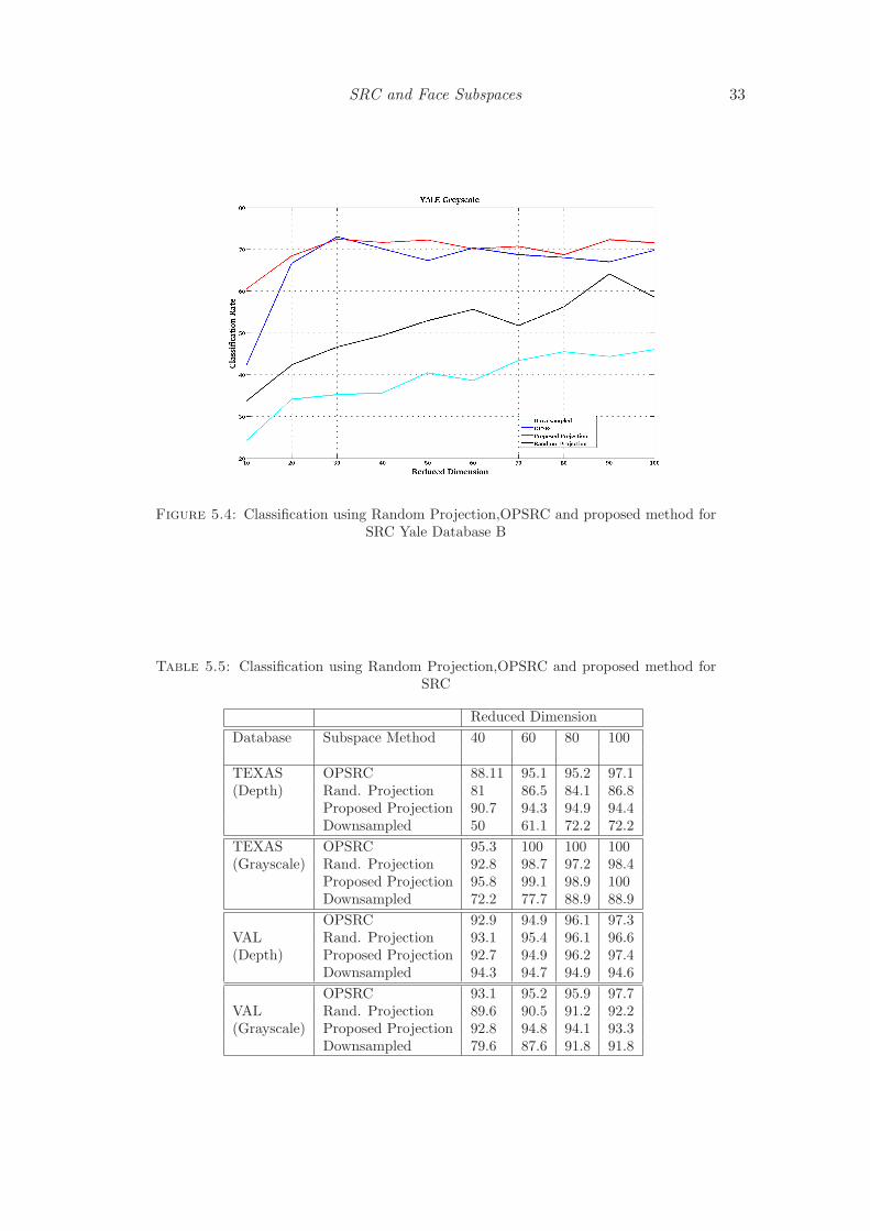
Reduced Dimension
Subspace Method 40 60 80 100OPSRC 70.1 70.3 68.0 69.8Rand, Projection 49.4 55.6 56.2 58.8Proposed Projection 71.6 70.1 68.7 71.5Downsampled 35.6 38.6 45.5 46
In order to analyze the robustness of the proposed algorithm under illumination vari-
ation, the algorithm was employed on the Yale database B, which has 64 different illumi-
nation pattern. The algorithm was tested with 10 subjects, and performed almost better
than OPSRC. The classification percentage for various dimensions is plotted in figure 5.4
and tabulated in table 5.4.

32 Spatio-Depth Face Recognition in l1Framework
(a) (b)
(c) (d)
Figure 5.3: Classification using Random Projection,OPSRC and proposed method forSRC (a)Texas Depth(b) Texas Greyscale (c) VAL depth (d) VAL greyscale
SRC and Face Subspaces 33
Figure 5.4: Classification using Random Projection,OPSRC and proposed method forSRC Yale Database B
Table 5.5: Classification using Random Projection,OPSRC and proposed method forSRC
Reduced Dimension
Database Subspace Method 40 60 80 100
TEXAS OPSRC 88.11 95.1 95.2 97.1(Depth) Rand. Projection 81 86.5 84.1 86.8
Proposed Projection 90.7 94.3 94.9 94.4Downsampled 50 61.1 72.2 72.2
TEXAS OPSRC 95.3 100 100 100(Grayscale) Rand. Projection 92.8 98.7 97.2 98.4
Proposed Projection 95.8 99.1 98.9 100Downsampled 72.2 77.7 88.9 88.9
OPSRC 92.9 94.9 96.1 97.3VAL Rand. Projection 93.1 95.4 96.1 96.6(Depth) Proposed Projection 92.7 94.9 96.2 97.4
Downsampled 94.3 94.7 94.9 94.6
OPSRC 93.1 95.2 95.9 97.7VAL Rand. Projection 89.6 90.5 91.2 92.2(Grayscale) Proposed Projection 92.8 94.8 94.1 93.3
Downsampled 79.6 87.6 91.8 91.8


Chapter 6
Conclusion
The availability of consumer depth cameras in the market have opened up a new gateway
for researches in computer vision and pattern recognition. This project uses of depth
information of face for face classification and has provided encouraging results. A database
of RGB/greyscale and depth image of 49 subjects was created The depth images resulted in
comparable performance with grey scale images for face recognition using l1 minimization
framework. Under varying illumination, SRC outperformed the conventional subspace
methods that uses PCA, LDA and LPP. Depth quantized images also gave comparable
recognition rates. The use of geometric contours that extract the low frequency variations
along those curves also gave encouraging results. The combination of SRC and subspace
methods gave comparable recognition rates with other well accepted algorithms. The
new proposed method has reduced the computational complexity of finding a projection
matrix, whose performance is at par with OPSRC.
This study can be taken ahead by exploring depth contour based approaches and ex-
ploring new descriptors for depth based face recognition. Manifold based face classification
is another fertile area that we are looking forward . More subspace projection methods
can be developed with lesser computation, and which can give classification comparable
to that of OPSRC. Exploring new feature vectors that is optimal for SRC is also a chal-
lenging area. There are numerous research going on to do SRC in real time, which still
remains an open challenge.
35


Bibliography
[1] W.Zhao, R.Chellappa, and A.Rosenfeld, “Face recognition: a literature survey,”
ACM Computer surveys, vol. 35, pp. 399–458, 2003.
[2] A. Samal and P. A. Iyengar, “Automatic recognition and analysis of human faces and
facial expressions: a survey,” Pattern Recognition, vol. 25, no. 1, pp. 65 – 77, 1992.
[3] A. F. Abate, M. Nappi, D. Riccio, and G. Sabatino, “2d and 3d face recognition: A
survey,” Pattern Recognition Letters, vol. 28, no. 14, pp. 1885 – 1906, 2007.
[4] A. Scheenstra, A. Ruifrok, and R. C. Veltkamp, “A survey of 3d face recognition
methods,” in In Lecture Notes in Computer Science, pp. 891–899, 2005.
[5] Microsoft, “Microsoft kinect,” 2011.
[6] P. V. amd Michael J Jones, “Robust real time face detection,” International Journal
of Computer Vision, vol. 57, no. 2, pp. 137–154, 2004.
[7] E.J.Candes, J.Romburg, and T.Tao, “Stable signal recovery from incomplete and
inaccurate measurements,” Communications on pure and Applied Mathematics,
pp. 1207–1223, 2006.
[8] E.J.Candes and T.Tao, “Near-optimal signal recovery from random projec-
tions:universal encoding strategies?,” IEEE trans on Information theory, vol. 52,
no. 12, pp. 5406–5425, 2006.
[9] J.Wright, A.Yang, A.Ganesh, S.Sastry, and Y.Ma, “Robust face recogition via sparse
representation,” IEEE Transactions on Pattern Analysis and Machine Intelligence,
vol. 31, no. 2, pp. 210–227, 2009.
[10] M. A. Turk and A. P. Pentland, “Face recognition using eigenfaces,” IEEE Computer
Society Conference on Computer Vision and Pattern Recognition, vol. 209, pp. 237–
260, 1998.
[11] P. Belhumeur, J. Hespanha, and D. Kriegman, “Eigenfaces vs. fisherfaces: recognition
using class specific linear projection,” Pattern Analysis and Machine Intelligence,
IEEE Transactions on, vol. 19, pp. 711 –720, jul 1997.
37

38 Spatio-Depth Face Recognition in l1Framework
[12] X. He, S. Yan, Y. Hu, P. Niyogi, and H.-J. Zhang, “Face recognition using laplacian-
faces,” Pattern Analysis and Machine Intelligence, IEEE Transactions on, vol. 27,
pp. 328 –340, march 2005.
[13] X.He and P.Niyogi, “Locality preserving projections,” in Proc. Conf. Advances in
Neural Information Processing, 2003.
[14] E. Bingham and H. Mannila, “Random projection in dimensionality reduction: ap-
plications to image and text data,” in Proceedings of the seventh ACM SIGKDD
international conference on Knowledge discovery and data mining, pp. 245–250, 2001.
[15] P. Sanguansat, “Two-dimensional random projection for face recognition,” in Per-
vasive Computing Signal Processing and Applications (PCSPA), 2010 First Interna-
tional Conference on, pp. 1107 –1110, sept. 2010.
[16] C.-Y. Lu, “Optimized projection for sparse representation based classification,” in
Proceedings of the 7th international conference on Advanced Intelligent Computing,
ICIC’11, pp. 83–90, 2011.
[17] C. Elkan, “Nearest neighbor classification,” 2011.
[18] J. Ho, M.-H. Yang, J. Lim, K.-C. Lee, and D. Kriegman, “Clustering appearances
of objects under varying illumination conditions,” in Proceedings of the 2003 IEEE
computer society conference on Computer vision and pattern recognition, pp. 11–18,
2003.
[19] D. L. Donoho and M. Elad Proceedings of the National Academy of Sciences of the
United States of America, vol. 100, no. 5, pp. 2197–202, 2003.
[20] E.Amaldi and V.Kann, “On the approximability of minimizing non-zero variables
or unsatisfied relations in linear systems,” Theoretical Computer Science, vol. 209,
pp. 237–260, 1998.
[21] Donoho.D, “For Most Large Undetermined systems of Linear Equations the minimal
L1 solution is also the sparsest solution,” Comm. Pure and Applied Math, vol. 59,
no. 6, pp. 797–829, 2006.
[22] M. Elad, Sparse and Redundant Representations:From Theory to Applications in Sig-
nal and Image Processing. Springer, 2010.
[23] H. Dibeklioglu, B. Gokberk, and L. Akarun, “Nasal region-based 3d face recogni-
tion under pose and expression variations,” Proceedings of the Third International
Conference on Advances in Biometrics, pp. 309–318, 2009.
[24] S. Gupta, M. K. Markey, and A. C. Bovik, “Anthropometric 3d face recognition,”
International journal of Computer Vision, vol. 90, no. 3, pp. 331–349, 2010.

Bibliography 39
[25] K. W. Bowyer, K. Chang, and P. Flynn, “A survey of approaches and challenges in
3d and multi-modal 3d+2d face recognition,” Comput. Vis. Image Underst., vol. 101,
pp. 1–15, Jan. 2006.
[26] H. Nguyen, “Linear subspace methods in face recognition,” Computer Science Re-
view, vol. 4, no. 1, pp. 1–17, 2011.
[27] L. Qiao, S. Chen, and X. Tan, “Sparsity preserving projections with applications to
face recognition,” Pattern Recognition, vol. 43, no. 1, pp. 331 – 341, 2010.
[28] J. Yang and D. Chu, “Sparse representation classifier steered discriminative projec-
tion,” in Proceedings of the 2010 20th International Conference on Pattern Recog-
nition, ICPR ’10, (Washington, DC, USA), pp. 694–697, IEEE Computer Society,
2010.
[29] S. Dasgupta and A. Gupta, “Compressed sensing with cross validation.,” 1999.
[30] R.ward, “An elementary proof of the Johnson-Lindenstrauss lemma,” 1999.
[31] S. Gupta, K. Castleman, M. K. Markey, and A. C. Bovik, “Texas 3d face recogni-
tion database,” IEEE Southwest Symposium on Image Analysis and Interpretation,
pp. 97–1, 2010.