spatio and efficient 1- 1 minimization based impulse noise ... · spatio and efficient ‘1-‘1...
TRANSCRIPT
Spatio and Efficient `1-`1 minimization basedImpulse Noise Removal in Gray Images Using
Dictionary LearningP.Jothibasu, Member, IAENG, and P.Rangarajan
Abstract—In natural images spatially adjacent image pixelshave similar pixel values and many patches of image pixelshave similar values. This similarity exploited for reducing thecomputation time required for de-noising and `1-`1 minimizationwas modified for efficient implementation. Using impulse noisedetector, noisy pixels were separated and from noise free pixelsDC values of image batches were calculated. This accurate DCvalue calculation improves the quality of the de-noised imageand preserves the details. Once noise is removed using efficient`1-`1 minimization, de-noised pixels will replace noisy pixel inthe corrupted image. The proposed algorithm gives superior peaksignal-to-noise ratio (PSNR) and structural similarity (SSIM)indices compared with the other state-of-the-art algorithms forgrey images.
Index Terms—Augmented Lagrangian Multiplier, DictionaryLearning, Impulse noise removal, Sparse Representation
I. INTRODUCTION
OUR brains are able to recognize a human face andother shapes and details in a fraction of time by
comparing it with the stored image in the neurons. Thebrain can recognize images corrupted to the certain extent.Brain can conjure the details behind the corrupted images,but our image processing algorithms fail to extract certaindetails from the image, when the image is corrupted bydifferent types of noises and other artifacts. Image details arerequired for image registration, segmentation, comparison,recognition of objects and retrieval. Image corruption mayoccur at any stage of image acquisition process. Imageacquisition process consists of three stages, viz., acquisition,transmission, and storage. Image acquisition is affected bythe image sensor, environment of the imaging subject, andimaging expert. In controlled environment image corruptionis less due to environment. In uncontrolled environmentlike underwater, extreme temperatures, hazardous situations,inaccessible remote areas, and uncontrolled light conditions,image corruption is unavoidable during acquisition. It re-quires a further processing of an image being essential toimprove the quality and to extract the details. Corruptionmay be blurring, Gaussian noise, defocus etc. During thetransmission of the acquired image from the imaging deviceto other places for dissemination, it may get corrupted.Transmission may be done using wired or wireless channelor memory. Imperfections in the channel and disturbances by
Manuscript received September 10, 2014; revised April 18, 2015.P.Jothibasu,Asst.Professor is with the Department of Electronics and In-
strumentation Engineering, R.M.K. Engineering College, Chennai-601206,India and also a Research Scholar, Anna University, Chennai-600025, Indiae-mail: ([email protected]).
R.Rangarajan, Professor, Department of Electrical and Electronics Engi-neering, R.M.D. Engineering College, Chennai-601206, India.
adjacent devices or equipments may corrupt the image. Thirdtype of image corruption occurs during storage of imagesin the memory. System constrained and limitation of thememory size leads to restricted number of images storedper memory device. Programming error and large numberof functionalities in user computer may lead to image cor-ruption in memory. Latest developments and technologicalbreakthrough are able to address certain issues in imageacquisition process to obtain noise free images. Still certaincases of image corruption are unavoidable. This necessitatesthe use of computationally efficient and qualitatively betterde-noising algorithms. With this objective many algorithmshave been designed. Image de-noising algorithms may belinear or non-linear based upon the relationship betweenthe input and the output. Linear algorithms [1], [2] aremean and its variants. Mean is used to remove the additiveGaussian noises and multiplicative noise. Mean filters failto de-noise the high density noises and leave smoothingeffect on the final image output [1], [2]. Non-linear filterssuch as median filters are more appropriate for removingsalt and pepper impulse noise in the image, perform betterto remove the outliers [1], [2]. Wavelet based de-noising isalso proposed for Gaussian corrupted images and specklenoise corrupted images. Different types of shrinkages suchas the soft shrinkage, hard shrinkage, Bayes shrink, Bishrinkare used to remove the noise in wavelet domain. Waveletbased de-noising methods are not capable of producing anappreciable de-noising performance for high density impulsenoises.
Recently Sparse representation and over-complete dictio-nary have received much attention [13], [15]–[17]. Sparserepresentation has been used in different post image pro-cessing applications such as super resolution [21], facialexpression recognition [25], compression [23], face recog-nition [22], text detection [26], Spectral Estimation [19],Pedestrian detection [27] and also in de-noising [24]. Thereare many sparse representation based de-noising methodssuch as K-SVD [30], Sparse representation using AugmentedLagrangian Multiplier based de-noising [10], `1-`1 [9], AK-SPR [8], `1-TV [7] and numerous other algorithms exist foradditive Gaussian de-noising, but very few research articleson salt and pepper impulse noise, de-noising have been pub-lished. In this paper Spatial and efficient `1-`1 minimization(SELL) based image de-nosing method is attempted.
The outline of the paper is as follows: In Section II, wereview some of the related works. In Section III , we proposea block diagram and algorithms for removal of fixed valueimpulse noise and random value impulse noise. In SectionIV, numerical experiments of the proposed algorithm and
IAENG International Journal of Computer Science, 42:3, IJCS_42_3_01
(Advance online publication: 10 July 2015)
______________________________________________________________________________________

its results are discussed to demonstrate the performanceimprovement by the proposed algorithm. In Section V,discussions on parameter settings, DC value calculationsand computational calculations are presented. Section VIconcludes the paper with findings and a statement on futuredirection.
II. DERIVATION OF `1- `1 MINIMIZATION
Sparse representation based salt and pepper impulse noiseremoval and random valued noise removal presented inreferences [9]–[12] are reviewed in this section. This sectionexplains optimization using Augmented Lagrangian Multi-plier based `1-`1-minimization and modification of algorithmfor efficient implementation. Subsection II-A presents de-noising model for the image restoration. Subsection II-Bexplains modification of `1-`1 minimization for efficientimplementation. Subsection II-C explains the similar imagebatch identification, grouping, and generation of represen-tative image batches for de-noising using efficient `1-`1minimization algorithm.
A. De-noising model
Let Im be the noise corrupted image of size W ×W andρ be the probability of noise intensity. Then corrupted imageis represented in equation 1.
Im(s) =
{Imd(s), ε ≤ ρIm0(s), ε > ρ
(1)
where s denotes two dimensional indices of image Im,Im0(s) denotes noise free pixels in the image, Imd(s)stands for noise corrupted image pixels, s varies from 1 toW and ε-is a random number with range of values [0,1].For Salt and Pepper Noise, Imd(s) takes either Immin
or Immax. For Random value noise, Imd(s) takes anyvalue in the range [Immin, Immax], which is independentlyand identically distributed. Im - recovered de-noised imagefrom corrupted image. Noisy image dimensions were Wx W. From noisy image, image batches were extracted byoverlapping batches of size
√M ×
√M . Total number of
batches from W ×W image is L = (W −√M + 1)2. M
is the number of rows in the dictionary (A) and N is thenumber of columns in the dictionary (A). M and N valuedetermination is explained in subsection V-A of section V.Each batch size,
√M ×
√M is reshaped into column vector
bi = [Im(si1), Im(si2), .....Im(siM )] ε RM . These batchesare represented as B.B = [b1, b2, ...bi, ..bL] ε R
M×L.bi = AiXi, i = 1, 2, 3, ...., L,bi is represented by over complete dictionary A,where A = [a1, a2, .....aW ] ε RM×W and X is a sparsecoefficent.
minA,X‖X‖0 + α ‖B −AX‖2 (2)
Where X = [X1, X2, ..XL] ε RW×L is the sparse co-efficient In equation 2 first term represents the sparse rep-resentation of X, which counts the few non-zero coefficientin the X, i.e sparse solution for X. ‖X‖0 is computationallyintensive and ‖B −AX‖2 represents root mean square errorbetween B and AX. Each column in A is called atom or basis,which represented as aj ε RM atom or basis, each atom is
normalized as ‖aj‖2 = 1. RMSE is susceptible to outlierssuch as salt and pepper impulse noise, so it is modified as`1 norm equation 3, to be robust enough for outliers.
minA,X‖X‖0 + α ‖B −AX‖1 (3)
Based on learned dictionary values A and sparse coefficientsX , de-noised image batches b are constructed as in equation4.
b = AX (4)
From batches b , image is reconstructed by averaging differ-ent estimates of same pixel.
B. Modification of `1 − `1 Minimization algorithmic equa-tions
Equation for de-noising algorithms presented in [10], [11],[28] contains redundant similar terms and non- adaptiveterms, which are reasons for high computational time andinaccurate results. Algorithmic equations were modified byderiving the new equation for Y, X and modifying theiterative shrinkage algorithms. Equation for X is given as
Xk = SHRINK(Xk−1 +Ak−1Y K
γUk−1,
1
γUk−1) (5)
γ = max(eig(AkT
A)) (6)
To simplify equation for Augmented Lagrangian MultiplierY, assume U and τ as in equation 7 and 8.
U = −Ak−1Xk−1 + b+Y k−1
µk−1(7)
τ =α
µk−1(8)
Equation for Y is rewritten as
PROJ(U, τ) = U − SHRINK(U, τ) (9)
SHRINK(U, τ) =
U − τ, U > τ
0, τ ≥ U ≥ τU + τ, U < τ
(10)
Equation 9 and equation for Y is written as in equation 11
Y = µPROJ(U, τ) = µU − µSHRINK(U, τ) (11)
Equation 10 is substituted in 9, to yield = µk−1U −τk−1SHRINK(U, τ)
= µk−1U −
µk−1U − µk−1τ, U > τ
0, τ ≥ U ≥ τµk−1U + µk−1τ, U < τ
(12)
Again rearranging equation 12 we obtain 13. Constraints for13 are not changed. We reduce the large amount calculationrequired to calculate the Y and also the overhead required forfinding Y from using PROJ and SHRINK. For large amountof image batches and number of iterations, it is essentialto have optimized equations and algorithms. The straightforward equation for Y is given in equation 13
Y =
µk−1τ, U > τ
µk−1U, τ ≥ U ≥ τ−µk−1τ, U < τ
(13)
IAENG International Journal of Computer Science, 42:3, IJCS_42_3_01
(Advance online publication: 10 July 2015)
______________________________________________________________________________________
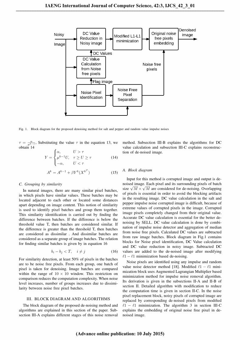
Fig. 1. Block diagram for the proposed denoising method for salt and pepper and random value impulse noises
τ = αµk−1 , Substituting the value τ in the equation 13, we
obtain 14
Y =
α, U > τ
µk−1U, τ ≥ U ≥ τ−α, U < τ
(14)
Ak = Ak−1 + βY k(XkT ) (15)
C. Grouping by similarity
In natural images, there are many similar pixel batches,in which pixels have similar values. These batches may belocated adjacent to each other or located some distancesapart depending on image content. This notion of similarityis used to identify pixel batches and group them together.This similarity identification is carried out by finding thedifference between batches. If the difference is below thethreshold value T, then batches are considered similar. Ifthe difference is greater than the threshold T, then batchesare considered as dissimilar . And dissimilar batches areconsidered as a separate group of image batches. The relationfor finding similar batches is given by in equation 16
bi − bj < T, i 6= j (16)
For similarity detection, at least 50% of pixels in the batchesare to be noise free pixels. From each group, one batch ofpixel is taken for denoising. Image batches are comparedwithin the range of 10 × 10 window. This restriction oncomparison reduces the computation complexity. When noiselevel increases, number of groups increases due to dissimi-larity between noise free pixel batches.
III. BLOCK DIAGRAM AND ALGORITHMS
The block diagram of the proposed de-noising method andalgorithms are explained in this section of the paper. Sub-section III-A explains different stages of this noise removal
method. Subsection III-B explains the algorithms for DCvalue calculation and subsection III-C explains reconstruc-tion of de-noised image.
A. Block diagram
Input for this method is corrupted image and output is de-noised image. Each pixel and its surrounding pixels of batchsize√M ×
√M are considered for de-noising. Overlapping
of pixels is essential in order to avoid the blocking artifactsin the resulting image. DC value calculation in the salt andpepper impulse noise corrupted image is difficult, because ofextreme values of corrupted pixels in the image. Corruptedimage pixels completely changed from their original value.Accurate DC value calculation is essential for the better de-noising by SELL. DC value calculation is done by combi-nation of impulse noise detector and aggregation of medianfrom noise free pixels. Calculated DC values are subtractedfrom raw image batches. Block diagram in Fig.1 containsblocks for Noise pixel identification, DC Value calculationand DC value reduction in noisy image. Subtracted DCvalues are added to the de-noised image after modifying`1− `1 minimization based de-noising.
Noise pixels are identified using any impulse and randomvalue noise detector method [18]. Modified `1 − `1 mini-mization block uses Augmented Lagrangian Multiplier basedminimization method for impulse noise removal algorithm.Its derivation is given in the subsections II-A and II-B ofsection II. Detailed algorithm with modification to reducethe computation time is given in section II-C. In the noisepixel replacement block, noisy pixels of corrupted image arereplaced by corresponding de-noised pixels from modified`1 − `1 minimization. The algorithm 3 in section III-Cexplains the embedding of original noise free pixel in de-noised image.
IAENG International Journal of Computer Science, 42:3, IJCS_42_3_01
(Advance online publication: 10 July 2015)
______________________________________________________________________________________

B. DC value calculation from noise free pixels
DC values are calculated accurately after detecting thenoisy pixel in the image batches based on any impulsenoise detection algorithm. From impulse detection binary flagimage f is generated . And binary image f is inverted andmultiplied by noisy image Im to obtain the noise free pixelsin the image as in equation 17. Median of noise free pixelsis considered as a DC value for each image batch, whichwill be subtracted from the image batches before applyingthe de-noising algorithm.
C. Final De-noised image
Binary flag image f, corrupted image Im and de-noisedimage Im from algorithm 1 are used to reconstruct the finalde-noised image as in equation 17.
Algorithm 1 DC value calculation from the noise free pixelsof noisy image patches.f - Binary flag image (1- noisy pixel, 0- noise free pixel)Im - Noisy image
1: Noise Free pixels in a image = (∼ f) Im2: Segregated noise free pixels and zero value pixels are
converted into batches of 8 x 8 pixels and each batch isconverted into column matrix.
3: Calculate Median of each column matrices.
Algorithm 2 Modified `1 − `1 Minimization using Aug-mented Lagrangian Multiplier
γ0 = max(eig(A0TA0)) - Initial valueb - DC values of subtracted image batchesInitialize X0 = 0, Y0 = 0, µ0 = 0.006A0= DCT Dictionary or random valuesWHILE(Stoping criterion is not satisfied, continue looping)
1: U=-Ak−1Xk−1+b+Y k−1
µk−1 , τ= αµk−1
2:
Y k =
α, U > τ
µk−1U, τ ≥ U ≥ τ−α, U < τ
3: Xk = SHRINK(Xk−1 + Ak−1Y K
γUk−1 , 1γUk−1 )
4: Ak = Ak−1 + βY k(XkT )
5: Ak = Ak.diag(∥∥ak0∥∥−1
2,∥∥ak1∥∥−1
2, ........
∥∥akN∥∥−1
2)
6: γ =max(eig(AkT
Ak))7: µk = 1.01µk−1
ENDWHILE
Algorithm 3 Final Image constructionf - Binary flag image (1- noisy pixel, 0- noise free pixel)Im - Noisy imageIm-De-noised pixels of noisy image by efficient `1− `1minimization for which binary Flag image value is 1
Final Image = (∼ f)Im+ (f)Im (17)
IV. EXPERIMENTS AND RESULTS
Experiments were conducted on many standard images.Images used to demonstrate the performance of the proposedalgorithm were girl, boat, baboon, Barbara, house, airplane,lake, bridge, peppers, Lena, parrot, cameraman etc. Most ofthe images used for testing were of size 256×256, if size ofthe image is 512× 512, which were converted to 256× 256image by considering the alternate pixels in the image.
The proposed algorithm was compared with many spatialand sparse representation based algorithms. Spatial domainalgorithms implemented for comparison were PSMF [4],ACWM [5], DWM [6]and Sparse representation based algo-rithms were L1-TV [7], AK-SPR [8]. Image metrics used forcomparison of algorithms performance were peak-signal tonoise ratio (PSNR), mean square error (MSE), and structuralsimilarity index (SSIM) [20]. The equation for metrics aregiven in 18, 19, and 20.
PSNR = 10 log10(2b − 1)2
MSE(18)
MSE =
N−1∑m=0
(M−1∑n=0
(Im(m,n)− Im0(m,n))2
)N2
(19)
SSIM =(2µ0µI0 + C1)(2σI0,0 + C2)
(µ20 + µ2
I0+ C1)(σ2
0 + σ2I0
+ C2)(20)
µ0- Mean intensities of original image, µI0 -Mean Intensitiesof restored image, σ2
I0,0-Co-variance of original and restored
image, σ0 - Standard deviation of the original image, σI0 -Standard deviation of the restored image image.
Dictionary size for the experiments was 64 × 256. Sizeof each basis or atom was 64 and the number of atoms was256. The size of the dictionary was fixed after experimentingvarious values for better PSNR value. The details of experi-ments are given in subsection A of section V. Dictionary sizewas fixed at 64× 256. After experiments µ value was fixedat 0.006. µ value was updated after each iteration. Numberof iterations for the loop was fixed at 25. And value for β= 0.001. DC values of the image batches were calculatedafter excluding noisy pixel values in the image batches andDC values were subtracted from the image batches beforeapplying SELL based de-noising algorithm to the imagebatches. DC values were calculated based on the median ofthe noise free pixels, instead of mean. Mean is suitable forDC value calculation of Gaussian noise corrupted images.In salt and pepper impulse noise and random value impulsenoise median is best suited for DC value calculation becauseof extreme values of noisy pixels.γ = max(eig(ATA))was calculated adaptively after updating and normalizing thedictionary A.
Two types of initial dictionary values were used in exper-iments. One is based on DCT as initial value for dictionaryand another is random values as a initial value for dictionary.The final dictionary values did not change after 40 itera-tions, regardless of initial dictionary values. The proposedalgorithm is robust to the initial dictionary values. If randommatrix is considered as an initial dictionary, γ value variesfrom larger value to smaller value during different iterationsof SELL algorithm. After 20 iterations γ value confinesitself to small range of values. In case of DCT matrix as
IAENG International Journal of Computer Science, 42:3, IJCS_42_3_01
(Advance online publication: 10 July 2015)
______________________________________________________________________________________

a b c d
e f g hFig. 2. The denoising results for airplane image corrupted by fixed value impulse noise a) original airplane image b) 10% of pixels corrupted by saltand pepper impulse noise c) PSMF d) ACWM e) DWM f) `1`1-DCT g) DL-INR h) The proposed method
Fig. 3. PSNR values for various percentage of fixed value impulse noisecorrupted pixels in airplane image
an initial dictionary matrix, γ value increases from smallervalue to larger value and stabilizes to constant value. Inthe experiments, noise density varied from 10% to 80%.After 90% salt and pepper noise and random value noise,dictionary updation fails due to very large Eigen values.Further refinement of algorithm is required for very highdensity noisy image, which will be carried out in our futurework.
A. Fixed value impulse noise removalIn fixed value or salt and pepper impulse noise removal
experiments, images were corrupted by impulse noise inthe range of 10% to 80%. Six standard images were usedfor the experiments. Fig.2,5,6 shows the result of proposedalgorithm and five other algorithms for 10%-30% noisecorrupted images.
Fig. 4. PSNR values for various percentage of fixed value impulse noisecorrupted pixels in barbara image
Fig.2(a) is original airplane image. Fig.2 (b) is 10% noisecorrupted image. Fig.2 (c), (d), (e), (f), (g) and (h) are thede-noising results of PSMF, ACWM,DWM, `1`1-DCT, DL-INR and the proposed algorithms. Among the de-noisingalgorithm results, PSMF, ACWM, DWM,`1`1-DCT, DL-INRalgorithms are able to recover an image with edge and detailpreservation. PSMF algorithm leaves few batches in the de-noised image. In `1`1-DCT algorithm smoothens the image.`1`1-DCT does not update its dictionary and its de-noisingresult is blurred. SELL algorithm’s de-noising results hasclarity and contrast of the image is comparable to that oforiginal and better than DL-INR algorithm.The letters on theairplane image is visible and better than other algorithms.Other algorithms results are poor for higher noise densities.PSNR values of spatial domain filters are less than the sparsedomain filters and the proposed algorithm has higher PSNR
IAENG International Journal of Computer Science, 42:3, IJCS_42_3_01
(Advance online publication: 10 July 2015)
______________________________________________________________________________________

a b c d
e f g hFig. 5. The denoising results for barbara image corrupted by fixed value impulse noise a) original barbara image b) 20% of pixels corrupted by salt andpepper impulse noise c) PSMF d) ACWM e) DWM f) `1`1-DCT g) DL-INR h) The proposed method
a b c d
e f g hFig. 6. The denoising results for girl image corrupted by fixed value impulse noise a) original girl image b) 30% of pixels corrupted by salt and pepperimpulse noise c) PSMF d) ACWM e) DWM f) `1`1-DCT g) DL-INR h) The proposed method
value than the other sparse domain algorithms as shown inFig.3.
Fig.5 (a) shows standard barbara image, Fig.5 (b) shows20% of pixels corrupted in barbara image. Fig.5 (c), (d), (e),(f), (g) and (h) shows the denoising results of the proposedalgorithm and other algorithms. Fig.5 (h) shows that theproposed algorithm able to recover details of background,scarf and cloth than other algoririthms.PSNR values of theDL-INR and `1`1-DCT are slightly less than the proposedalgorithm PSNR values as shown in Fig.4.
Fig.6 shows the denoising results of algorithms, originalimage and corrupted image of girl standard image. Thedenoising results of the proposed algorithm is better thanother algorithms. The proposed algorithm recovers the detailslike eyes, tie and hair of the girl image better than allalgorithms.Fig.6 (c) is the denoising result of PSMF algo-rithm, which contains few unfiltered pixels. Results of DL-INR and `1`1-DCT contains blurred eyes and other details.ACWMF and DWMF algorithm outputs are comparable withthe proposed algoritm output. For higher density noises these
IAENG International Journal of Computer Science, 42:3, IJCS_42_3_01
(Advance online publication: 10 July 2015)
______________________________________________________________________________________

Fig. 7. PSNR values for various percentage of fixed value impulse noisecorrupted pixels in girl image
Fig. 8. PSNR values for various percentage of fixed value impulse noisecorrupted pixels in baboon image
two algorithms produces degraded images. PSNR valuesof the ACWMF and DWMF are less than the proposedalgorithm PSNR values as shown in Fig.7.
Fig.3,4,7,8,9,10 shows the plots between PSNR and fixedvalue impulse noise density for standard images. In eachplot proposed algorithm is compared with many standardalgorithms. The proposed algorithm outperforms all otherstate-of-the-art algorithms in terms of peak signal to noiseratio (PSNR) and structural similarity index(SSIM). FromFig.3,4,7,8,9,10, it is understood that PSNR of SELL algo-rithm is appreciably higher than the other algorithms.
SSIM results shown in Table I compare the DL-INRalgorithm with SELL algorithm. SELL algorithm performsbetter in terms of structural restoration of images corruptedby the salt and pepper impulse noise. SSIM values arecalculated from the average of 10 experiments for eachimage.
B. Random value impulse noise removal
Random value impulse noise was applied to standardtest images and the performance of the different de-noisingalgorithms were obtained for comparison. Noise densityvaried from 10% to 80% and the corresponding PSNR and
Fig. 9. PSNR values for various percentage of fixed value impulse noisecorrupted pixels in boat image
Fig. 10. PSNR values for various percentage of fixed value impulse noisecorrupted pixels in house image
SSIM values were calculated and tabulated. Fig.11,14,17shows denoising results of various algorithms for variousstandard images and different noise levels.
Fig.11 shows the denoising results of 50% of pixels inboat image corrupted by the random value impulse noise.Denoising results of various algorithms were shown in figureFig.11 (c), (d), (e), (f), (g) and (h). When 50% of pixelsare corrupted by random value impulse noise, most of thespatial domian algorithms gives a blurred image. The detailslike poles at the top of the boat, stones at the bottom of theboat and letters on the back of the boat were blurred beyondrecognition in other algorithm results than the proposedalgorithm.PSNR values were plotted against percentage ofpixels corrupted by the random values impulse noise shownin Fig.13 and PSNR values also higher for the proposedalgorithm than other algorithms.
Fig.14 shows the original test image baboon, 70% ofpixels corrupted by random value impulse noise and de-noising results of standard de-noising algorithms are shown.The proposed (SELL) algorithm performs better in termsof detail preserving and contrast preservation. Finer detailslike eyes, nose, and hair were restored better than all theother algorithms. ACWMF and DWMF could not restore
IAENG International Journal of Computer Science, 42:3, IJCS_42_3_01
(Advance online publication: 10 July 2015)
______________________________________________________________________________________

TABLE ISSIM VALUE FOR THE IMAGES OF DIFFERENT SALT AND PEPPER NOISE LEVELS FOR SIX IMAGES
Image/ House Boat Barbara Baboon Girl AirplaneNoise DL-INR SELL DL-INR SELL DL-INR SELL DL-INR SELL DL-INR SELL DL-INR SELL
10 0.9467 0.9918 0.8552 0.9741 0.9446 0.9912 0.7149 0.9558 0.9661 0.9946 0.8832 0.983020 0.9283 0.9779 0.8004 0.9351 0.9241 0.9774 0.6239 0.9060 0.9547 0.9872 0.8641 0.963130 0.8947 0.9558 0.7361 0.8884 0.8976 0.9520 0.5136 0.8521 0.9396 0.9726 0.8112 0.935840 0.8658 0.9211 0.6406 0.8442 0.8639 0.9099 0.4472 0.7917 0.9229 0.9577 0.7725 0.900250 0.8027 0.8915 0.5892 0.7808 0.8162 0.8839 0.3896 0.7184 0.9000 0.9359 0.7212 0.849760 0.7501 0.8441 0.5339 0.7285 0.7523 0.8431 0.3494 0.6384 0.8777 0.9212 0.6838 0.809270 0.7156 0.8009 0.4869 0.6599 0.7202 0.8030 0.2984 0.5530 0.8620 0.9018 0.6533 0.758280 0.7127 0.7708 0.4708 0.6006 0.7131 0.7717 0.2815 0.4595 0.8542 0.8835 0.6356 0.7098
a b c d
e f g hFig. 11. The denoising results for boat image corrupted by random value impulse noise a) original boat image b) 50% of pixels corrupted by randomvalue impulse noise c) PSMF d) ACWM e) DWM f) `1`1-DCT g) DL-INR h) The proposed method
Fig. 12. PSNR values for various percentage of random value impulsenoise corrupted pixels in airplane image
or recover a any information from the corrupted image asshown in Fig.14 (d) and (e). `1`1-DCT and DL-INR couldrecover or de-noise the image, but most of the details wereblurred. PSNR values were plotted against percentage of
Fig. 13. PSNR values for various percentage of random value impulsenoise corrupted pixels in boat image
pixels corrupted by the random values impulse noise shownin Fig.15 and PSNR values of the proposed algorithm ishigher than other algorithms.
Fig.17 shows the denoising result for house image with
IAENG International Journal of Computer Science, 42:3, IJCS_42_3_01
(Advance online publication: 10 July 2015)
______________________________________________________________________________________

a b c d
e f g hFig. 14. The denoising results for baboon image corrupted by random value impulse noise a) original baboon image b) 70% of pixels corrupted byrandom value impulse noise c) PSMF d) ACWM e) DWM f) `1`1-DCT g) DL-INR h) The proposed method
Fig. 15. PSNR values for various percentage of random value impulsenoise corrupted pixels in baboon image
80% of pixels were corrupted by random value impulsenoise. Fig.17 (b) shows the 80% of pixels corrupted image.Fig.17 (c), (d), (e), (f), (g) and (h) shows de-noising resultof PSMF, ACWMF, DWMF, `1`1-DCT, DL-INR and theproposed algorithm. spatial domain filters were failed toproduce a significant improvement to the corrupted image.The proposed algorithhm, DL-INR and `1`1-DCT denoisngresults were significantly better for 80% of pixels corruptedimage. Compared with DL-INR algorithm SELL performsbetter for high level of noise corrupted images.
Plots between peak signal to noise ratio and 10%-80% per-centage of pixels corrupted by random value impulse noisecorrupted image shown in Fig.12,13,15,16,18,19. SELL givesconsistently better PSNR value than the other algorithms.PSNR improvement in certain test images house and girl aremore than 3 db. In higher noise percentage PSNR difference
Fig. 16. PSNR values for various percentage of random value impulsenoise corrupted pixels in girl image
is much higher than the lower noise percentage, which provesthe robustness of the SELL algorithm.
V. DISCUSSIONSA. Parameter settings
The proposed algorithm has many parameters. Selectionof appropriate values for these parameters helps to achievea better peak signal to noise ratio and visual quality of theimage. The parameters were α,β,γ and µ. Among the param-eters β directly determines the learning rate of the dictionary.α, γ and µ indirectly influence the learning rate throughequation for Lagrangian multiplier Y and sparse coefficientX. β value is fixed at 0.001 for balanced dictionary learning.It has been fixed after heuristics experiments.
Value of α determines the relationship between sparserepresentation term and data fidelity term. Depending on
IAENG International Journal of Computer Science, 42:3, IJCS_42_3_01
(Advance online publication: 10 July 2015)
______________________________________________________________________________________

a b c d
e f g hFig. 17. The denoising results for house image corrupted by random value impulse noise a) original house image b) 80% of pixels corrupted by saltand pepper impulse noise c) PSMF d) ACWM e) DWM f) `1`1-DCT g) DL-INR h) The proposed method
TABLE IIα VALUES FOR VARIOUS PERCENTAGE OF FIXED VALUE IMPULSE NOISE PIXELS IN DIFFERENT IMAGES
Noise Percentage 10 20 30 40 50 60 70 80α 0.7295 0.6629 0.5963 0.5375 0.4235 0.3835 0.3235 0.2343
Fig. 18. PSNR values for various percentage of random value impulsenoise corrupted pixels in house image
α value de-noising performance varies. Highly accurate αvalue is required for faster learning of dictionary and visualquality. small variation in α value leads to large variation inqualtiy of image and dictionary. Table II gives α value fordifferent noise levels of all images. α is used in AugmentedLagrangian Multiplier equation Y and indirectly influencesX and A. For faster convergence, α may be converted toadaptively varying parameter. Further research is required todetermine the α values from the corrupted image, instead oftabulation based values.
Another parameter which influences both dictionary (A)
Fig. 19. PSNR values for various percentage of random value impulsenoise corrupted pixels in barbara image
and sparse coefficients (X) is γ whose value is made adaptiveby including it in algorithm‘s steps. γ value is updated bydictionary updates. Initial dictionary values affect γ value.Initial dictionary value may be DCT matrix or random ma-trix. If random value matrix as a initial dictionary matrix (A),variations in γ value shown in Fig.20, γ value or maximumeigen value decreases from large value to moderate valueand stabilizes after 20 iterations. If initial dictionary matrix(A) is DCT matrix, Fig.21 shows that γ value increases fromsmall value and stabilizes after 20 iterations. Our future workwill improve the dictionary learning by considering different
IAENG International Journal of Computer Science, 42:3, IJCS_42_3_01
(Advance online publication: 10 July 2015)
______________________________________________________________________________________

Fig. 20. Maximum eigen value γ for random values as an initial dictionary
Fig. 21. Maximum eigen value γ for DCT matrix value as an initialdictionary
Fig. 22. various µ values and PSNR value
initial values like walsh, hadamard, haar transform matricesas a initial dictionary matrix.
From Fig.22 µ value is fixed at 0.006 after calculatingPSNR values for the range of 0.001 to 0.009. For µ=0.006value all standard images used in this algorithm attainsmaximum PSNR value. Dictionary size is also important for
Fig. 23. Number of atoms N in a dictionary and PSNR values
Fig. 24. Number of elements in an atom M and PSNR value
Fig. 25. Number of Iterations K for algorithm and PSNR value
better PSNR and SSIM [20] values. For K-SVD [29], DL-INR [9], ALM [11] algorithms dictionary size is 64 × 256.Dictionary size for this algorithm is obtained by plottingPSNR value against number of atoms in a dictionary (N). Nvalue varied from 81 to 512. For 256 atoms in a dictionaryPSNR reaches the maximum value as shown in Fig.23 andN is fixed at 256.
IAENG International Journal of Computer Science, 42:3, IJCS_42_3_01
(Advance online publication: 10 July 2015)
______________________________________________________________________________________

a) K=1 b) K=3 c) K=7 d) K=10
e) K=13 f) K=16 g) K=20 h) K=25Fig. 26. Learned dictionary for different iterations of the algorithm for 10% random value impulse noise corrupted house image and DCT matrix as ainitial value
a) K=1 b) K=3 c) K=7 d) K=10
e) K=13 f) K=16 g) K=20 h) K=25Fig. 27. Dictionary for different iterations of the algorithm for 10% random value impulse noise corrupted house image and random value as a initialDictionary value
In order to determine the number elements in an atom(M), PSNR value is ploted against M value. Fig.24 showsthe plot for PSNR and M value, M value ranges from 16to 121. PSNR peaks at M=64. From the above conclusiondictionary size for this algorithm is 64× 256.
Number of iterations required for this algorithm is de-termined after calculating PSNR value for various numberof iterations(K), which is shown in Fig.25. For K value 25this algorithm attains maximum PSNR value. The number
of iterations is fixed at 25 for all images and both fixedvalue and random value impulse noises. From number ofexperiments conducted for different test images, numberof non-zero elements in the sparse coefficient matrix Xdecreases with increase in noise density for both salt andpepper impulse noise and random value impulse noise. It isobserved that the number of non-zero elements in X is verysparse for 80% noise level.
Fig.26 shows the dictionary learned during many iterations
IAENG International Journal of Computer Science, 42:3, IJCS_42_3_01
(Advance online publication: 10 July 2015)
______________________________________________________________________________________

TABLE IIIAVERAGE EXECUTION TIME FOR DIFFERENT IMAGES AND NOISE PIXEL
PERCENTAGES (TIME IN SECONDS)
algorithm/ 10 20 30 40 50 60Noise%PSMF 1 1 1 1 1 1ACWM 56 57 57 56 56 56DWM 258 257 257 257 256 256L1-TV 10 13 14 14 16 17`1`1-DCT 74 74 72 70 67 65AK-SPR 2153 1581 1567 904 1101 1815DL-INR 81 81 79 77 74 72SMLL 51 52 52 52 52 52
of algorithm with DCT matrix as an initial dictionary matrix.Fig.27 shows the dictionary learned during many iterationsof algorithm with random matrix as a initial dictionarymatrix. From Fig.26,27 final dictionary appears to be similarfor different initial values for dictionary and proves therobustness of the algorithm for different initial values ofdictionary.
B. Computational analysis
Our algorithm was implemented in MATLAB2007 withcomputer containing an Intel Core2 Duo T7500 processor at2.00GHz speed and 2GB DDR RAM. Computational timewas greatly reduced by converting a two stage algorithm in`1−`1 minimization into single stage algorithm. By choosingappropriate values for parameters, the number of iterationswas reduced. And combining the similar terms in the algo-rithms, redundant computations were removed,which in turnreduced computation required for efficient calculations of Xand A. Average time was calculated for six images of 10experiments per noise level, for both impulse and randomvalue noise being tested and tabulated in Table III. Imagesize was restricted to uniform 256 x 256. The proposed SELLalgorithm is faster than the DL-INR algorithm, AK-SPR, and`1`1-DCT algorithm. In `1`1-DCT dictionary is not updatedas in DL-INR, SELL algorithms, so it is faster than DL-INRbut slower than SELL. The proposed SELL is faster due tooptimization and simplification of algorithm steps to reducethe number of multiplications and additions and modificationin implementation of PROJ and SHRINK.
VI. CONCLUSION
In this paper spatial and efficient `1 − `1 minimizationbased fixed and random valued impulse noise removal al-gorithm was presented. Image batches formed from noisyimage. In noisy image, noisy pixels were identified usingany impulse noise detector and from noise free pixels DCvalues were calculated. DC values were subtracted fromnoisy image batches. Before applying denoising algorithmson noisy image, similar pixel batches were grouped. Fromeach group representation batches were used for denoising.The `1−`1 minimization algorithm was modified into singlestage algorithm from two stage algorithm in order to reducethe number of iterations required for de-noising and reducingthe computation time. After denoising representative batcheswere used to replace all similar noisy batches. AccurateDC value calculation improved the edge preservation andnoise suppression. Our algorithm results were compared
with spatial domain methods and sparse representation basedalgorithms. The proposed algorithm outperforms all otheralgorithms in terms of de-noising performance and preserv-ing image details. In our future work we intend to applyour algorithm to color images,artifacts removal and also toimprove the updation speed of the ALM coefficients andmodify the algorithm for very high density noise images.
REFERENCES
[1] J.Astola, P.Kuosmanen, Fundamentals of Nonlinear Digital Filtering,CRC Press, Newyork, 1997.
[2] I.Pitas, A.N.Venetsanopoulos, Non linear Digital Filters, Principles andApplications, Springer Science, 1990.
[3] David.C.Lay, Linear Algebra and Its Applications, Addision-Wesley,Reading, MA, 1994.
[4] Z. Wang and D. Zhang,“Progressive switching median filter for theremoval of impulse noise from highly corrupted images”, IEEE Trans-actions on Circuits and Systems, vol.46, pp.78-80, 1999.
[5] T. Chen and H. R. Wu, “Adaptive impulse detection using Center-Weighted median filters”,IEEE Signal processing letters, vol.8, pp.1-3,Jan 2001.
[6] Y. Dong and S. Xu , “A new directional weighted median filter forremoval of random-valued impulse noise”, IEEE Signal ProcessingLetters, vol.14, no.3, pp.193-196, 2007.
[7] M. Nikolova, “A variational approach to remove outliers and impulsenoise”, Journal of Mathematical Imaging and Vision, vol.20, no. 1-2,pp.99-120, 2004.
[8] P. Bouboulis , K. Slavakis and S. Theodoridis,“Adaptive kernel-basedimage denoising employing semi-parametric regularization”, IEEETransactions on Image Processing, vol.19, no.6, pp.1465 -1479, 2010.
[9] S. Wang , Q. Liu , Y. Xia , P. Dong , J. Luo , Q. Huang and D.D. Feng, “Dictionary learning based impulse noise removal via `1− `1minimization”, Signal Processing, vol.93, no.9, pp.2696-2708, 2013.
[10] Q. Liu , J. Luo , S. Wang , M. Xiao and M. Ye,“An augmented La-grangian multi-scale dictionary learning algorithm”, EURASIP Journalon Advances in Signal Processing, vol.2011, no.1, pp.1-16, 2011.
[11] Q. Liu , S. Wang , J. Luo , Y. Zhu and M. Ye, “An augmented La-grangian approach to general dictionary learning for image denoising”,Journal of Visual Communication and Image Representation, vol.23,no.5, pp.753-766, 2012.
[12] S.H.Chan, R.Khoshabeh, K.B.Gibson, P.E.Gill, T.Q.Nguyen,“An Aug-mented Lagrangian Method for Total Variation Video Restoration”,IEEE Transactions On Image Processing, vol.20, pp.3097-3111, 2011.
[13] D. L. Donoho , “Compressed sensing”, IEEE Transactions on Infor-mation Theory, vol.52, no.4, pp.1289-1306, 2006.
[14] D. P. Bertsekas,Constrained Optimization and Lagrange MultiplierMethod’s, Athena Scientific, Reimont,MA,1982.
[15] M. Elad and M. Aharon ,“Image denoising via sparse and redundantrepresentations over learned dictionaries”, IEEE Transactions on ImageProcessing, vol.15, no.12, pp.3736 -3745, 2006.
[16] M. Aharon , M. Elad and A. M. Bruckstein, “On the uniqueness ofovercomplete dictionaries, and a practical way to retrieve them”, LinearAlgebra and Applications, vol.416, pp.48-67, 2006.
[17] M. Elad, Sparse and redundant representations from theory to applica-tions in signal and Image processing, Springer, 2010.
[18] S.J.Horng, L.Y. Hsu, T.Li, S.Qiao, X.Gong, H.H.Chou, M.K.Khan,“Using Sorted Switching Median Filter to remove high-density impulsenoises",Journal of Visual Communication and Image Representation,Volume 24, Issue.7, pp.956-967, October 2013.
[19] Isabel M.P.Duarte, Jose M.N.Vieira, Paulo.J.S.G. Ferreira and DanielF.Albuquerque, “High resolution spectral Estimation Using BP viaCompresssive sensing" ,in Lecture Notes in Engineering and ComputerScience:Proceedings of The World Congress on Engineering and Com-puter Science 2012,WCECS 2012, 24-26 October, 2012, San Francisco,USA, pp699-704.
[20] Z. Wang, A. C. Bovik, H. R. Sheikh, and E. P. Simoncelli, “Imagequality assessment: From error measurement to structural similarity",in IEEE Transactions on Image Processing, vol.13, no.4, pp.600 -612,2004.
[21] Subramanyam Ravishankar, Nagadastagiri Reddy.C and M.V.Joshi,“Single Image Super Resolution Using Sparse Image and GLCMstatistics as priors", Lecture Notes in Engineering and Computer Sci-ence:Proceedings of The World Congress on Engineering 2011,WCE2011, 6-8 July, 2011, London, U.K., pp1563-1566.
[22] Allen Y. Yang, Zihan Zhou, Arvind Ganesh, S. Shankar Sastry, YiMa, “Fast `1-Minimization Algorithms For Robust Face Recognition",IEEE Transactions on Image Processing, vol.22, no.8, pp.3234-3246,2013.
IAENG International Journal of Computer Science, 42:3, IJCS_42_3_01
(Advance online publication: 10 July 2015)
______________________________________________________________________________________

[23] M.Andrecut, “Sparse Random Approximation and Lossy Compres-sion", IAENG International Journal of Applied Mathematics, vol.38,no.3, pp205-214, 2004.
[24] A.Gramfort, C.Poupon, M.Descoteaux, “Denoising and fast diffusionimaging with physically constrained sparse dictionary learning".MedicalImage Analysis, Vol.18, pp.36-49, 2014.
[25] M.R. Mohammadi, E. Fatemizadeh,M.H. Mahoor, “PCA based dic-tionary building for accurate facial expression recognition via sparserepresentation", Journal of Visual Communication and Image Repre-sentation, vol.25, pp.1082-1092, 2014.
[26] M.Zhao, S.Li,J.Kwok, “Text detection in images using sparse represen-tation with discriminative dictionaries", Image and Vision Computing,vol.28, pp.1590-1599, 2010.
[27] Ran Xu, Jianbin Jiao, Baochang Zhang, Qixiang Ye, “Pedestrian de-tection in images via cascaded `1 norm minimization learning method",Pattern recognition, vol.45, pp.2573-2583, 2012.
[28] Y.Xiao, T.Y.Zeng, J.Yu, M.K.and Ng,“Restoration of images corruptedby mixed Gaussian-impulse noise via `1-`0 minimization", Patternrecognition, vol.44, pp.1708-1720, 2011.
[29] Michal Aharon, Michael Elad, and Alfred Bruckstein, “K-SVD: AnAlgorithm for Designing Overcomplete Dictionaries for Sparse Repre-sentation", IEEE Transactions on Signal Processing, vol.54, pp.4311-4322, 2006.
[30] Rauhut.H, Schnass.K, and Vandergheynst.P, “Compressed Sensing andRedundant Dictionaries", IEEE Transactions on Information Theory,vol.54, pp.2210-2219, 2008.
[31] Gribonval.R, Schnass.K, “Dictionary identification: sparse matrix-factorization via `1-minimization", IEEE Transactions on InformationTheory, vol.56, pp.3523-3539, 2010.
[32] W.Yin, S.Osher, D.Gold farb, J.Darbon, “Bregman iterative algorithmsfor `1 minimization with application to compressed sensing", SIAMJournal on Imaging Sciences, vol.1, no.1, pp.143-168, 2008.
P.Jothibasu was born in 1978 in India. Hereceived B. E. from Bharathiyar University and M.E. from Anna university. Presently he is doing parttime doctoral degree in Anna University, Chennai.Currently he is working as an Assistant Professorin Electronics and Instrumentation EngineeringDepartment, R.M.K Engineering College, Chen-nai. His research interests are signal processing,Image processing and embedded systems.
P.Rangarajan was born in 1969 in India. Hereceived B. E. in Electrical and Electronics Engi-neering from Bharthiyar University, M.E. and Ph.D. from Anna University. He is presently workingas a Professor in Electrical and Electronics En-gineering Department, R.M.D. Engineering Col-lege, Kavaraipettai, Chennai. His research interestsare VLSI, VLSI system Design, signal processingand Image processing. He has successfully guidedmany doctoral degree scholars. He also carried outresearch projects funded by national and interna-
tional Organizations.
IAENG International Journal of Computer Science, 42:3, IJCS_42_3_01
(Advance online publication: 10 July 2015)
______________________________________________________________________________________