spark v atmega16 hardware manual 2010-04-26ccgroup/lab_pages/experiment_files/hw.pdf · © nex...
TRANSCRIPT

SPARK V ATMEGA16 Hardware Manual
© NEX Robotics Pvt. Ltd. and ERTS Lab IIT Bombay, INDIA 1

SPARK V ATMEGA16 Hardware Manual
© NEX Robotics Pvt. Ltd. and ERTS Lab IIT Bombay, INDIA 2
SPARK V HARDWARE MANUAL
SPARK V ATMEGA16 Hardware Manual
© NEX Robotics Pvt. Ltd. and ERTS Lab IIT Bombay, INDIA 3
Version 1.36 April 24, 2011 Documentation author Sachitanand Malewar, NEX Robotics Pvt. Ltd. Vinod Desai, NEX Robotics Pvt. Ltd. Credits: All the team of NEX Robotics

SPARK V ATMEGA16 Hardware Manual
© NEX Robotics Pvt. Ltd. and ERTS Lab IIT Bombay, INDIA 4
Notice The contents of this manual are subject to change without notice. All efforts have been made to ensure the accuracy of contents in this manual. However, should any errors be detected, NEX Robotics welcomes your corrections. You can send us your queries / suggestions at [email protected]
Content of this manual is released under the Creative Commence cc by-nc-sa license. For legal information refer to: http://creativecommons.org/licenses/by-nc-sa/3.0/legalcode
Robot’s electronics is static sensitive. Use robot in static free environment. Read the hardware and software manual completely before start using this robot
Recycling: Almost all of the robot parts are recyclable. Please send the robot parts to the recycling plant after its operational life. By recycling we can contribute to cleaner and healthier environment for the future generations.
SPARK V ATMEGA16 Hardware Manual
© NEX Robotics Pvt. Ltd. and ERTS Lab IIT Bombay, INDIA 5
Index
1. Introduction
6
2. SPARK V ATMEGA16
7
3. Using SPARK V Robot
11
4. Programming Spark V ATMEGA16 Robot
46
5. Pin Functionality
88
6. PC Based Control Using Serial Communication
90
7. Robot Control using ‘GUI’ for SPARK V ATMEGA16
96
SPARK V ATMEGA16 Hardware Manual
© NEX Robotics Pvt. Ltd. and ERTS Lab IIT Bombay, INDIA 6
1. Introduction Thanks for choosing the SPARK V mobile robot platform. SPARK V will give you good exposure to the world of robotics and embedded systems. Thanks to its innovative architecture and adoption of the ‘Open Source Philosophy’ in its software and hardware design, you will be able to create and contribute to complex applications that run on this platform, helping you acquire expertise as you spend more time with them. Safety precautions:
• Robot’s electronics is static sensitive. Use robot in static free environment. • Read the assembling and operating instructions before working with the robot. • If robot’s battery low buzzer starts beeping, immediately charge the batteries. • To prevent fire hazard, do not expose the equipment to rain or moisture. • Refrain from dismantling the unit or any of its accessories once robot is assembled. • Never allow NiMH battery to deep discharge. • Mount all the components with correct polarity. • Keep wheels away from long hair or fur. • Keep the robot away from the wet areas. Contact with water will damage the robot. • To avoid risks of fall, keep your robot in a stable position. • Do not attach any connectors while robot is powered ON. • Never leave the robot powered ON when it is not in use.
Inappropriate Operation: Inappropriate operation can damage your robot. Inappropriate operation includes, but is not limited to:
• Dropping the robot, running it off an edge, or otherwise operating it in an irresponsible manner.
• Interfacing new hardware without considering compatibility • Overloading the robot above its payload capacity. • Exposing the robot to wet environments. • Continuing to run the robot after hair, yarn, string, or any other item has become
entangled in the robot’s axles or wheels. • All other forms of inappropriate operation. • Using robot in areas prone to static electricity.
• Read carefully paragraphs marked with caution symbol. Note: For Spark V accessories refer to Chapter 10: Spark V Accessories
SPARK V ATMEGA16 Hardware Manual
© NEX Robotics Pvt. Ltd. and ERTS Lab IIT Bombay, INDIA 7
2. SPARK V ATMEGA16 Spark V is a low cost robot designed for robotics hobbyists and enthusiasts. It is jointly designed by NEX Robotics with Department of Computer Science and Engineering, IIT Bombay. Spark V will help you get acquainted with the world of robotics and embedded systems. Thanks to its innovative architecture and adoption of the ‘Open Source Philosophy’ in its software and hardware design, you will be able to create and contribute to complex applications that run on this platform, helping you acquire expertise as you spend more time with them.
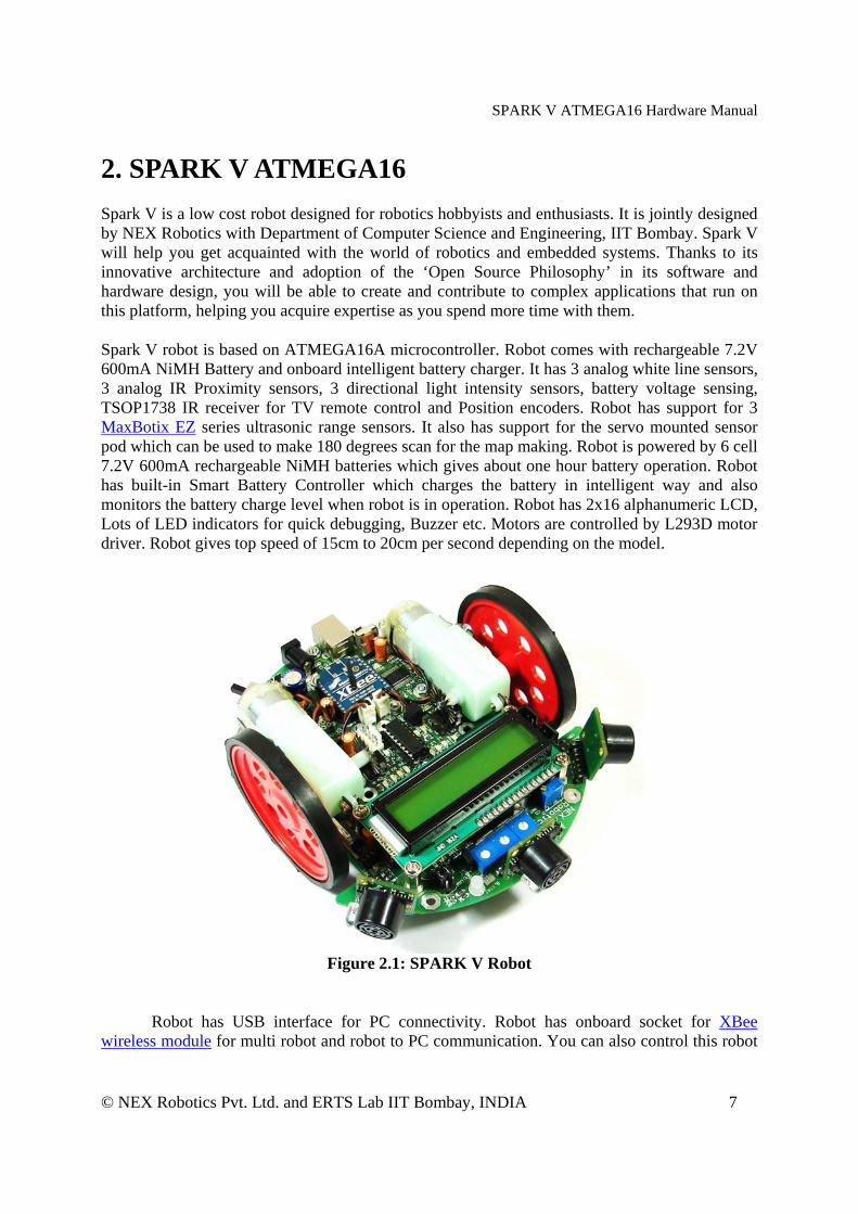
Spark V robot is based on ATMEGA16A microcontroller. Robot comes with rechargeable 7.2V 600mA NiMH Battery and onboard intelligent battery charger. It has 3 analog white line sensors, 3 analog IR Proximity sensors, 3 directional light intensity sensors, battery voltage sensing, TSOP1738 IR receiver for TV remote control and Position encoders. Robot has support for 3 MaxBotix EZ series ultrasonic range sensors. It also has support for the servo mounted sensor pod which can be used to make 180 degrees scan for the map making. Robot is powered by 6 cell 7.2V 600mA rechargeable NiMH batteries which gives about one hour battery operation. Robot has built-in Smart Battery Controller which charges the battery in intelligent way and also monitors the battery charge level when robot is in operation. Robot has 2x16 alphanumeric LCD, Lots of LED indicators for quick debugging, Buzzer etc. Motors are controlled by L293D motor driver. Robot gives top speed of 15cm to 20cm per second depending on the model.
Figure 2.1: SPARK V Robot
Robot has USB interface for PC connectivity. Robot has onboard socket for XBee wireless module for multi robot and robot to PC communication. You can also control this robot
SPARK V ATMEGA16 Hardware Manual
© NEX Robotics Pvt. Ltd. and ERTS Lab IIT Bombay, INDIA 8
over GUI from NEX Robotics over wired (USB) and wireless (XBee wireless modules) medium. Firmware (.hex file) is loaded on the robot using Bootloader Utility from NEX Robotics. There is no need to use external programmer. There are additional empty soldering points at each pin of the microcontroller so that you can access them for customization of the robot.
Note: You need to buy MaxBotix EZseries ultrasonic range sensors, XBee wireless module separately.
SPARK V ATMEGA16 Hardware Manual
© NEX Robotics Pvt. Ltd. and ERTS Lab IIT Bombay, INDIA 9
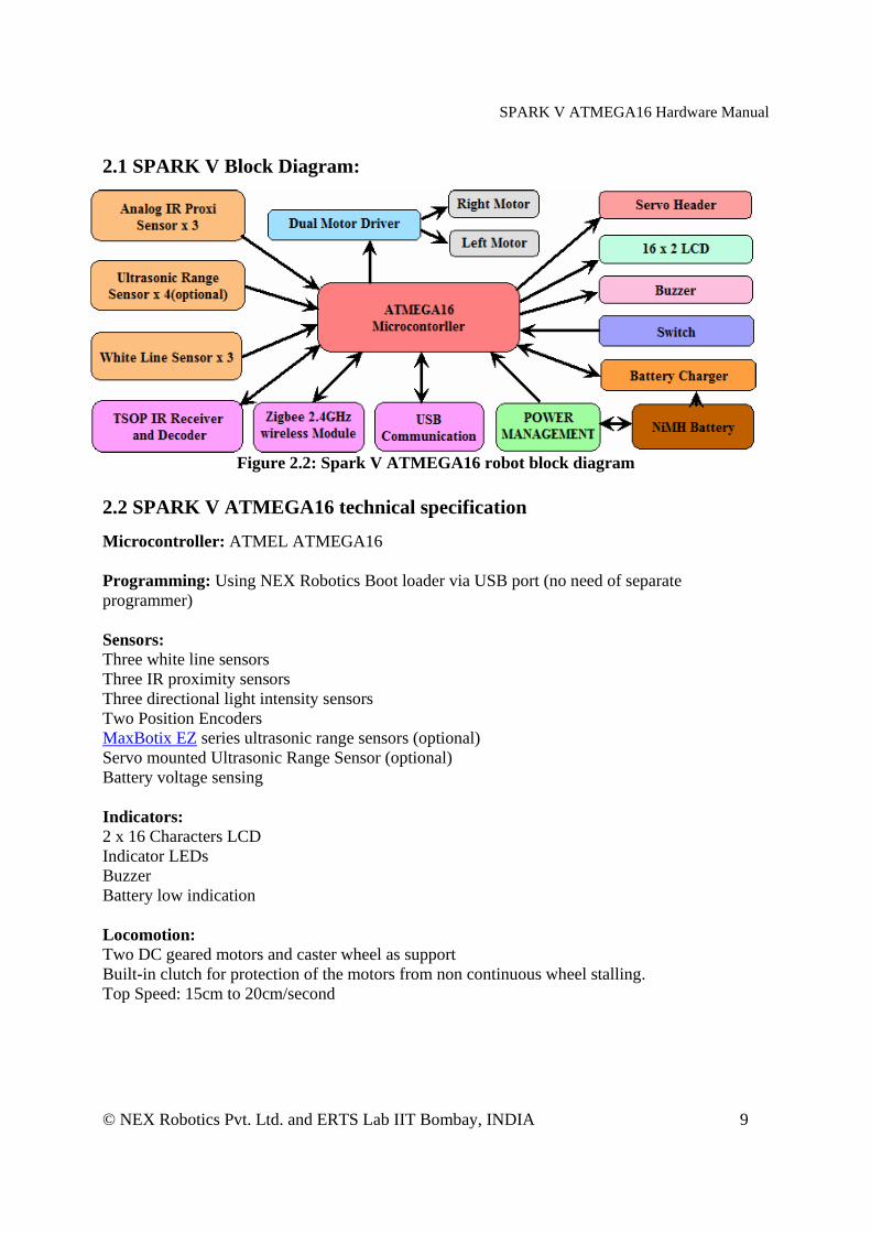
2.1 SPARK V Block Diagram:
Figure 2.2: Spark V ATMEGA16 robot block diagram
2.2 SPARK V ATMEGA16 technical specification Microcontroller: ATMEL ATMEGA16 Programming: Using NEX Robotics Boot loader via USB port (no need of separate programmer) Sensors: Three white line sensors Three IR proximity sensors Three directional light intensity sensors Two Position Encoders MaxBotix EZ series ultrasonic range sensors (optional) Servo mounted Ultrasonic Range Sensor (optional) Battery voltage sensing Indicators: 2 x 16 Characters LCD Indicator LEDs Buzzer Battery low indication Locomotion: Two DC geared motors and caster wheel as support Built-in clutch for protection of the motors from non continuous wheel stalling. Top Speed: 15cm to 20cm/second
SPARK V ATMEGA16 Hardware Manual
© NEX Robotics Pvt. Ltd. and ERTS Lab IIT Bombay, INDIA 10
Operational Modes: Standalone (Autonomous Control) PC as master and robot as slave Distributed (multi robot communication) Communication: USB Communication using FT232 USB to Serial Converter Simplex infrared communication (From infrared remote to robot) ZigBee (IEEE 802.15.4) (Wireless) (Robots to Robots and Robots to PCs )(Optional) Dimensions: Diameter: 15cm Height: 7cm Power: 6 cell 7.2V 600mA rechargeable NiMH batteries (Batteries included) Onboard Smart Battery Controller charges the battery in intelligent way and also monitors the battery charge level when robot is in operation. Locomotion: Two DC geared motors and caster wheel as support Built-in clutch protection for the motors from non continuous stalling of the wheel Top Speed: 15cm to 20cm/second Optional Accessories: Servo mounted Ultrasonic range sensor for 180 degree scan Servo mounted directional light intensity sensor for 180 degree scan MaxBotix EZ series ultrasonic range sensors XBee wireless module Software Support: GUI Based control, AVR studio, WINAVR Microsoft robotics studio Visual Programming Language Requires: AC adaptor with exact 12VDC with 1Amp. current rating for battery charging.

SPARK V ATMEGA16 Hardware Manual
© NEX Robotics Pvt. Ltd. and ERTS Lab IIT Bombay, INDIA 11
3. Using SPARK V Robot In this chapter various components of the robot and their principal of operations are explained in detail. It is very important that user go through chapter before starting to use robot. Spark V robot has 6 important modules:
1. Power management 2. Sensing 3. Actuation (locomotion) 4. Other peripherals 5. Communication 6. Intelligence (microcontroller)
Figure 3.1: SPARK V ATMEGA16 robot top view
SPARK V ATMEGA16 Hardware Manual
© NEX Robotics Pvt. Ltd. and ERTS Lab IIT Bombay, INDIA 12
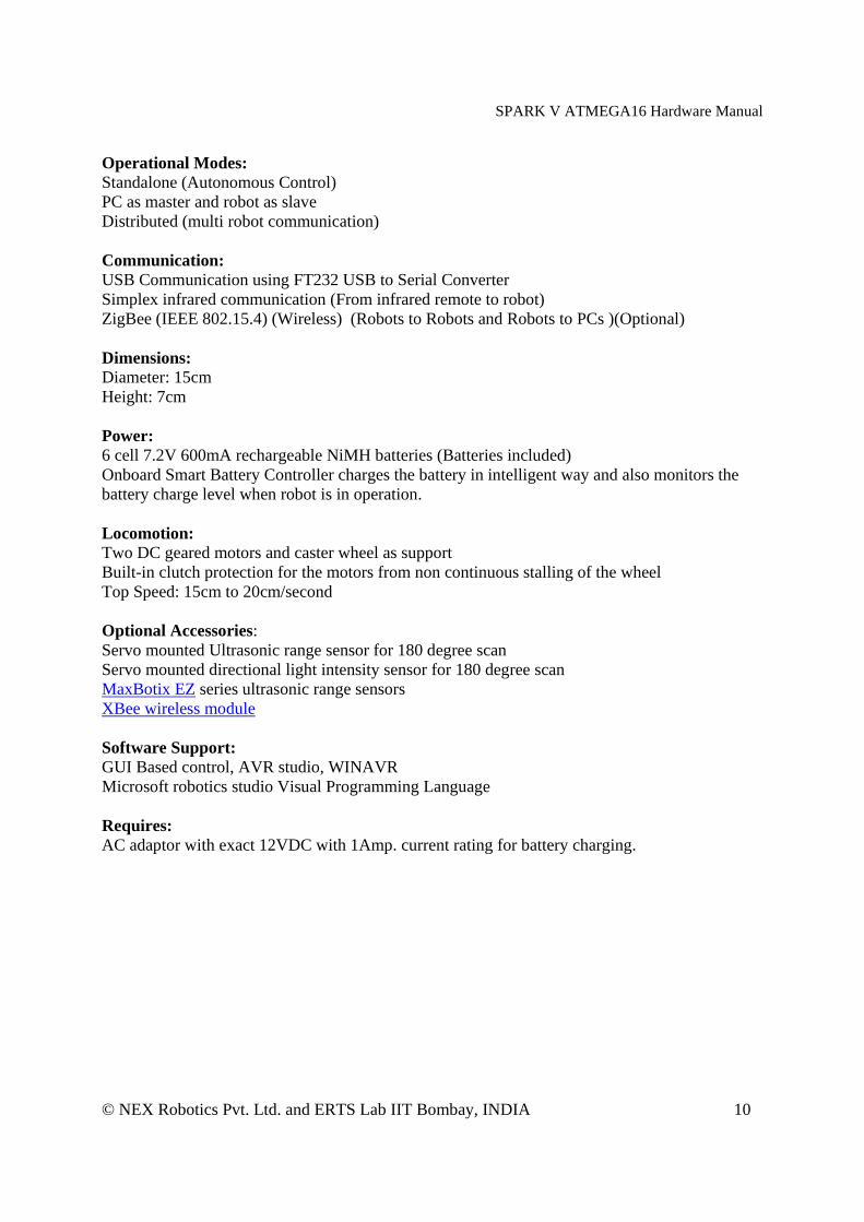
3.1 Connections
Figure 3.2: Spark V component layout top view

SPARK V ATMEGA16 Hardware Manual
© NEX Robotics Pvt. Ltd. and ERTS Lab IIT Bombay, INDIA 13
Figure 3.3: Spark V component layout bottom view

SPARK V ATMEGA16 Hardware Manual
© NEX Robotics Pvt. Ltd. and ERTS Lab IIT Bombay, INDIA 14
3.2 Powering up Spark V
Spark V is powered by 7.2 V 600 mA rechargeable NiMH battery. It gives about one hour of operation. Battery is connected with the robot using 4 pin relimate connector which is located at the bottom in the left sided of the caster wheel.
For safety during the transportation robot’s battery connector is disconnected. Connect the battery connector before first use.
Figure 3.4: Battery pack in Spark V
Before connecting the battery pack, make sure that power switch of the robot is off. Robot has onboard smart battery controller which can charge the installed batteries. You need to charge the battery before first use. Use any AC adaptor / SMPS which can give accurate 12V DC and 1Amp current. For battery charging procedure refer to section 3.4. For robot powering options, refer to section 3.5.
3.3 Power management system on the SPARK V Spark V is powered by 7.2 V 600 mA rechargeable NiMH battery. When it is fully discharged voltage drops to about 7V. Battery pack should not be discharged below 6V (1V per cell) for extended battery life. Nickel Metal Hydride batteries must be recharged using smart charging circuit which follows the appropriate charging profile for the batteries. Spark V has onboard smart battery controller which monitors battery status while charging. To avoid any damage to the batteries, only use onboard battery charger.
Power management block on the SPARK V performs following functions. 1. Battery low warning in case battery is below critical level 2. Regulated supply for onboard payload. 3. Battery charging when robot is powered off and external battery charger is
connected.
SPARK V ATMEGA16 Hardware Manual
© NEX Robotics Pvt. Ltd. and ERTS Lab IIT Bombay, INDIA 15
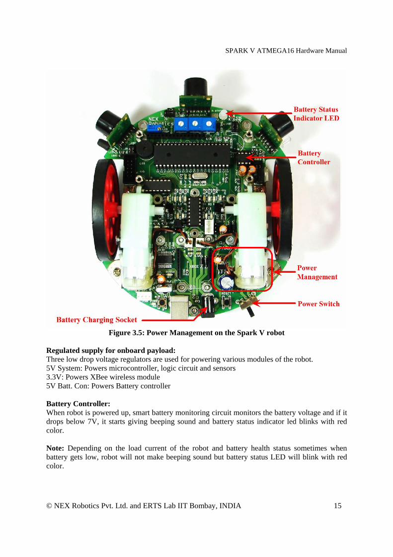
Figure 3.5: Power Management on the Spark V robot
Regulated supply for onboard payload: Three low drop voltage regulators are used for powering various modules of the robot. 5V System: Powers microcontroller, logic circuit and sensors 3.3V: Powers XBee wireless module 5V Batt. Con: Powers Battery controller Battery Controller: When robot is powered up, smart battery monitoring circuit monitors the battery voltage and if it drops below 7V, it starts giving beeping sound and battery status indicator led blinks with red color. Note: Depending on the load current of the robot and battery health status sometimes when battery gets low, robot will not make beeping sound but battery status LED will blink with red color.
SPARK V ATMEGA16 Hardware Manual
© NEX Robotics Pvt. Ltd. and ERTS Lab IIT Bombay, INDIA 16
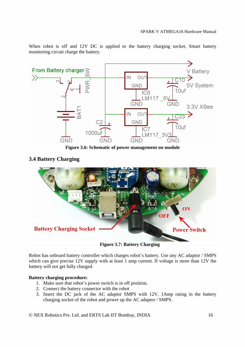
When robot is off and 12V DC is applied to the battery charging socket, Smart battery monitoring circuit charge the battery.
Figure 3.6: Schematic of power management on module
3.4 Battery Charging
Figure 3.7: Battery Charging
Robot has onboard battery controller which charges robot’s battery. Use any AC adaptor / SMPS which can give precise 12V supply with at least 1 amp current. If voltage is more than 12V the battery will not get fully charged. Battery charging procedure:
1. Make sure that robot’s power switch is in off position. 2. Connect the battery connector with the robot 3. Insert the DC jack of the AC adaptor SMPS with 12V, 1Amp rating in the battery
charging socket of the robot and power up the AC adaptor / SMPS.
SPARK V ATMEGA16 Hardware Manual
© NEX Robotics Pvt. Ltd. and ERTS Lab IIT Bombay, INDIA 17
Now smart battery controller will sense the presence of the battery charging supply and will start charging the battery. It will terminate the battery charging once battery is fully charged. During the charging process battery status can be monitored on the battery status LED. Refer to the table below for battery charging status interpretation using battery status LED.
Table 3.1: Battery status indicator LED interpretation
Important: If you are using battery which is not used for long time then you have to charge it and discharge it at least few times to bring the battery to its full storage capacity. To do this you can load any motion program from the “Experiments” folder which is located in the documentation CD and discharge the batteries after charging.
Warning: • Many transformer based AC adaptor’s voltage is 30 to 40% higher when there is no load.
Make sure that AC adaptor’s no load voltage is precisely 12V else it will damage the robot and battery.
• If you are using SMPS, then make sure that it doesn’t have mains leakage current flowing through the DC supply. Else when you touch the robot, this high voltage leakage current will damage the robot’s electronics.
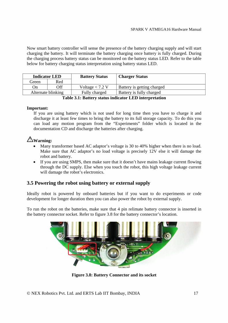
3.5 Powering the robot using battery or external supply Ideally robot is powered by onboard batteries but if you want to do experiments or code development for longer duration then you can also power the robot by external supply. To run the robot on the batteries, make sure that 4 pin relimate battery connector is inserted in the battery connector socket. Refer to figure 3.8 for the battery connector’s location.
Figure 3.8: Battery Connector and its socket
Indicator LED Green Red
Battery Status Charger Status
On Off Voltage < 7.2 V Battery is getting charged Alternate blinking Fully charged Battery is fully charged

SPARK V ATMEGA16 Hardware Manual
© NEX Robotics Pvt. Ltd. and ERTS Lab IIT Bombay, INDIA 18
To run the robot on the external supply, remove the 4 pin relimate battery connector from its socket and use another 4 pin relimate connector to give external supply. External supply should be in between 7.1 to 9V. Red and Orange are the positive terminals. Brown and Black are the negative terminals.
Warning: • Do not exceed 9V voltage limit else robot will get damaged. • Battery connector socket is not reverse polarity protected. If supply is applied in reverse
polarity, it will immediately damage the robot. • Use only good quality bench top power supply to power the robot using external supply.
Use of AC adaptor or cheap SMPS is not recommended.
3.6 Battery Maintenance Fully charged NiMH battery will get completely discharged with in a week of storage. Always charge the battery before use. If fully charged battery is kept in storage for about a month and afterwards even if it’s fully charged again, it can deliver only 1/3rd power of its rating. In such case to restore battery to its full potential again, perform at least 2-3 charge discharge cycles. To ensure long life, charge battery at least once a week and discharge it till robot starts giving battery low warning. Before storage, charge the battery again. For discharging the battery quickly, you can load any program from the “Experiments” folder of the documentation CD. Disconnect the battery connector if robot is to be stored for long duration of time. 3.7 Motion control
Spark V robot has two DC geared motors in differential drive configuration along with the third caster wheel for the support. Robot has top speed of about 15/20cm per second. Using this configuration, the robot can turn with zero turning radius by rotating one wheel in clockwise direction and other in counterclockwise direction. Robot’s motors have built-in clutch for protection of the motor’s gears from non continuous wheel stalling. Motion control involves direction control and velocity control. Motors are controlled by L293D dual motor driver which can provide up to 600mA of current to each motor. To change the direction of the motor, appropriate logic levels (High/Low) are applied to L293D’s direction control pins. Velocity control is done using Pulse Width Modulation (PWM). LEDs are connected at the input and the output stage of the motor driver for quick interpretation of the motion commands.
Pulse Width Modulation for velocity control: Pulse width modulation is a process in which duty cycle of constant frequency square wave is modulated to control power delivered to the load i.e. motor.
SPARK V ATMEGA16 Hardware Manual
© NEX Robotics Pvt. Ltd. and ERTS Lab IIT Bombay, INDIA 19
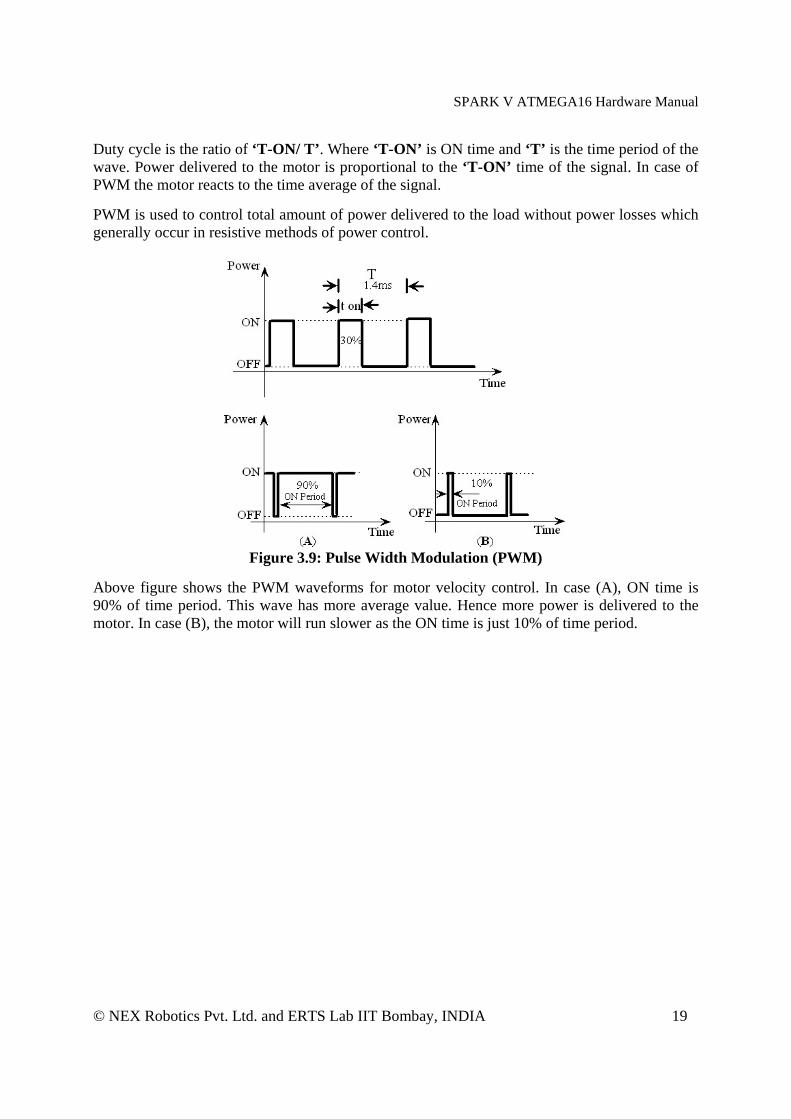
Duty cycle is the ratio of ‘T-ON/ T’. Where ‘T-ON’ is ON time and ‘T’ is the time period of the wave. Power delivered to the motor is proportional to the ‘T-ON’ time of the signal. In case of PWM the motor reacts to the time average of the signal. PWM is used to control total amount of power delivered to the load without power losses which generally occur in resistive methods of power control.
Figure 3.9: Pulse Width Modulation (PWM)
Above figure shows the PWM waveforms for motor velocity control. In case (A), ON time is 90% of time period. This wave has more average value. Hence more power is delivered to the motor. In case (B), the motor will run slower as the ON time is just 10% of time period.

SPARK V ATMEGA16 Hardware Manual
© NEX Robotics Pvt. Ltd. and ERTS Lab IIT Bombay, INDIA 20
Figure 3.10: Motion Control
In the figure 3.10 area marked with the red border are the LEDs connected to the input stage of the L293D motor driver. Area marked by Blue border shows LEDs connected to the output of the motor driver. Orange border marks position encoder output LEDs. Yellow border marks left and right motor connectors. Microcontroller pin connections
Microcontroller Pin Function PD5 (OCR1AL) Pulse width modulation for the left motor (velocity control) PD4 (OCR1BL) Pulse width modulation for the right motor (velocity control)
PB0 Left motor direction control PB1 Left motor direction control PB2 Right motor direction control PB3 Right motor direction control
Table 3.2: Pin functions for the motion control LED Direction Indications
Direction Output (Red / Yel.) Direction
L1 (Red) (I/P) PB0
L2 (Red) (I/P) PB1
PL (Yel.) (I/P) PD3
R1 (Red) (I/P) PB2
R2 (Red) (I/P) PB3
PR (Yel.) (I/P) PD4 Left
Motor Right Motor
FORWARD 0 1 1 1 0 1 Yellow Yellow REVERSE 1 0 1 0 1 1 Red Red

SPARK V ATMEGA16 Hardware Manual
© NEX Robotics Pvt. Ltd. and ERTS Lab IIT Bombay, INDIA 21
RIGHT (Left wheel forward, Right wheel backward)
0 1 1 0 1 1 Yellow Red
LEFT (Left wheel backward, Right wheel forward,)
1 0 1 1 0 1 Red Yellow
SOFT RIGHT (Left wheel forward,, Right wheel stop)
0 1 1 0 0 1 Yellow Off
SOFT LEFT (Left wheel stop, Right wheel forward,)
0 0 1 1 0 1 Off Yellow
SOFT RIGHT 2 (Left wheel stop, Right wheel backward)
0 0 1 0 1 1 Off Red
SOFT LEFT 2 (Left wheel backward, Right wheel stop)
1 0 1 0 0 1 Red Off
HARD STOP 0 0 1 0 0 1 Off Off SOFT STOP (Free running stop) 1 1 1 1 1 1 Off Off
Table 3.3: Direction and PWM LED indications
SPARK V ATMEGA16 Hardware Manual
© NEX Robotics Pvt. Ltd. and ERTS Lab IIT Bombay, INDIA 22
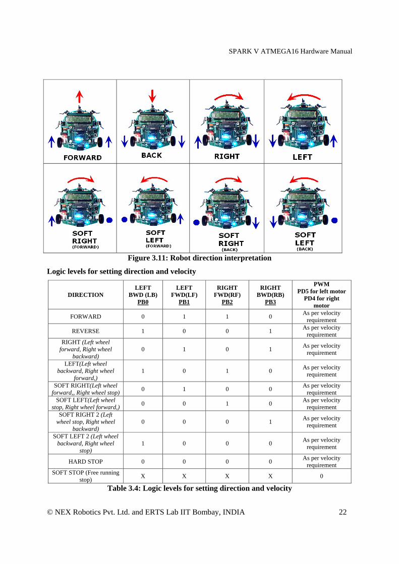
Figure 3.11: Robot direction interpretation
Logic levels for setting direction and velocity
DIRECTION LEFT
BWD (LB) PB0
LEFT FWD(LF)
PB1
RIGHT FWD(RF)
PB2
RIGHT BWD(RB)
PB3
PWM PD5 for left motor
PD4 for right motor
FORWARD 0 1 1 0 As per velocity requirement
REVERSE 1 0 0 1 As per velocity requirement
RIGHT (Left wheel forward, Right wheel
backward) 0 1 0 1 As per velocity
requirement
LEFT(Left wheel backward, Right wheel
forward,) 1 0 1 0 As per velocity
requirement
SOFT RIGHT(Left wheel forward,, Right wheel stop) 0 1 0 0 As per velocity
requirement SOFT LEFT(Left wheel
stop, Right wheel forward,) 0 0 1 0 As per velocity requirement
SOFT RIGHT 2 (Left wheel stop, Right wheel
backward) 0 0 0 1 As per velocity
requirement
SOFT LEFT 2 (Left wheel backward, Right wheel
stop) 1 0 0 0 As per velocity
requirement
HARD STOP 0 0 0 0 As per velocity requirement
SOFT STOP (Free running stop) X X X X 0
Table 3.4: Logic levels for setting direction and velocity

SPARK V ATMEGA16 Hardware Manual
© NEX Robotics Pvt. Ltd. and ERTS Lab IIT Bombay, INDIA 23
Figure 3.12: Motion Control
3.8 Position Encoders Position encoders give position / velocity feedback to the robot. It is used in closed loop to control robot’s position and velocity. Position encoder consists of slotted disc which rotates between optical encoder (optical transmitter and receiver). When slotted disc moves in between the optical encoder we get square wave signal whose pulse count indicates position and time period / frequency indicates velocity. Optical encoder MOC7811 is used for position encoder on the robot. It consists of IR LED and the photo transistor mounted in front of each other separated by a slot in black opaque casing with small slot shaped window facing each other. When IR light falls on the photo transistor it gets in to saturation and gives logic 0 as the output. In absence of the IR light it gives logic 1 as output. A slotted encoder disc is mounted on the wheel is placed in between the slot. When encoder disc rotates it cuts IR illumination alternately because of which photo transistor gives square pulse train as output. Output from the position encoder is cleaned using Schmitt trigger based inverter (not gate) IC CD40106. CD40106 also drives left and right position encoder status LEDs. For more details, refer to figure 3.13.

SPARK V ATMEGA16 Hardware Manual
© NEX Robotics Pvt. Ltd. and ERTS Lab IIT Bombay, INDIA 24
Figure 3.13: Position Encoders
Figure 3.14: Position encoder assembly
Calculation of position encoder resolution: Case 1: Robot is moving forward or backward (encoder resolution is in mm)
Wheel diameter: 7cm Wheel circumference: 7cm * 3.14 = 21.980cm = 219.80mm Number slots on the encoder disc: 17

SPARK V ATMEGA16 Hardware Manual
© NEX Robotics Pvt. Ltd. and ERTS Lab IIT Bombay, INDIA 25
Position encoder resolution: 219.80 mm / 17 = 12.92mm / pulse.
Case 2: Robot is turning with one wheel rotating clockwise while other wheel is rotating anti clockwise. Center of rotation is in the center of line passing through wheel axel and both wheels are rotating in opposite direction (encoder resolution is in degrees)
Distance between Wheels = 11.6cm
Radius of Circle formed in 3600 rotation of Robot = Distance between Wheels / 2 = 5.8 cm
Distance Covered by Robot in 3600 Rotation = Circumference of Circle traced = 2 x 5.8 x 3.14 = 36.4 cm or 364mm
Number of wheel rotations in 3600 rotation of robot = Circumference of Traced Circle / Circumference of Wheel = 364 / 219.80 = 1.65
Total pulses in 3600 Rotation of Robot = Number of slots on the encoder disc / Number of wheel rotations of in 3600 rotation of robot = 17 x 1.65 = 28.05 (approximately 28)
Position Encoder Resolution in Degrees = 360 / 28 = 12.85 degrees per count
Case 3: Robot is turning with one wheel stationary while other wheel is rotating clockwise or anti clockwise. Center of rotation is center of the stationary wheel (encoder resolution is in degrees)
In this case only one wheel is rotating and other wheel is stationary so robot will complete its 3600 rotation with stationary wheel as its center. Radius of Circle formed in 3600 rotation of Robot = Distance between Wheels = 11.6 cm
Distance Covered by Robot in 3600 Rotation = Circumference of Circle traced = 2 x 11.6 x 3.14 = 72.848 cm or 728 mm
Number of wheel rotations of in 3600 rotation of robot = Circumference of Traced Circle / Circumference of Wheel
= 728 / 219.80 = 3.312
Total pulses in 3600 Rotation of Robot = Number of slots on the encoder disc / Number of wheel rotations of in 3600 rotation of robot = 17 x 3.312 = 56.304 (approximately 56) Position Encoder Resolution in Degrees = 360 /56

SPARK V ATMEGA16 Hardware Manual
© NEX Robotics Pvt. Ltd. and ERTS Lab IIT Bombay, INDIA 26
= 6.42 degrees per count
Figure 3.15: Position encoder schematics
3.9 Infrared proximity and Directional light intensity sensors Infrared proximity sensors are used to detect proximity of any obstacles in the short range. IR proximity sensors have about 10cm sensing range. Spark V robot has 3 IR proximity sensors. In the absence of the obstacle there is no reflected light hence no leakage current will flow through the photo diode and output voltage of the photodiode will be around 5V. As obstacle comes closer, more light gets reflected and falls on the photo diode and leakage current flowing through the photo diode starts to increase which causes voltage across the diode to fall. If IR LEDs are disabled using jumpers then same photo diodes works as directional light intensity sensors.
Figure 3.16: Infrared proximity and Directional light intensity sensors and Jumper settings
for enabling IR Proximity sensors Figure 3.6 shows 3 Infrared proximity and Directional light intensity sensors on the Spark V robot. Sensors are numbered as 1, 2 and 3 from left to right in clockwise direction. In all the manuals this numbering convention will be used for addressing the particular IR sensor.
SPARK V ATMEGA16 Hardware Manual
© NEX Robotics Pvt. Ltd. and ERTS Lab IIT Bombay, INDIA 27
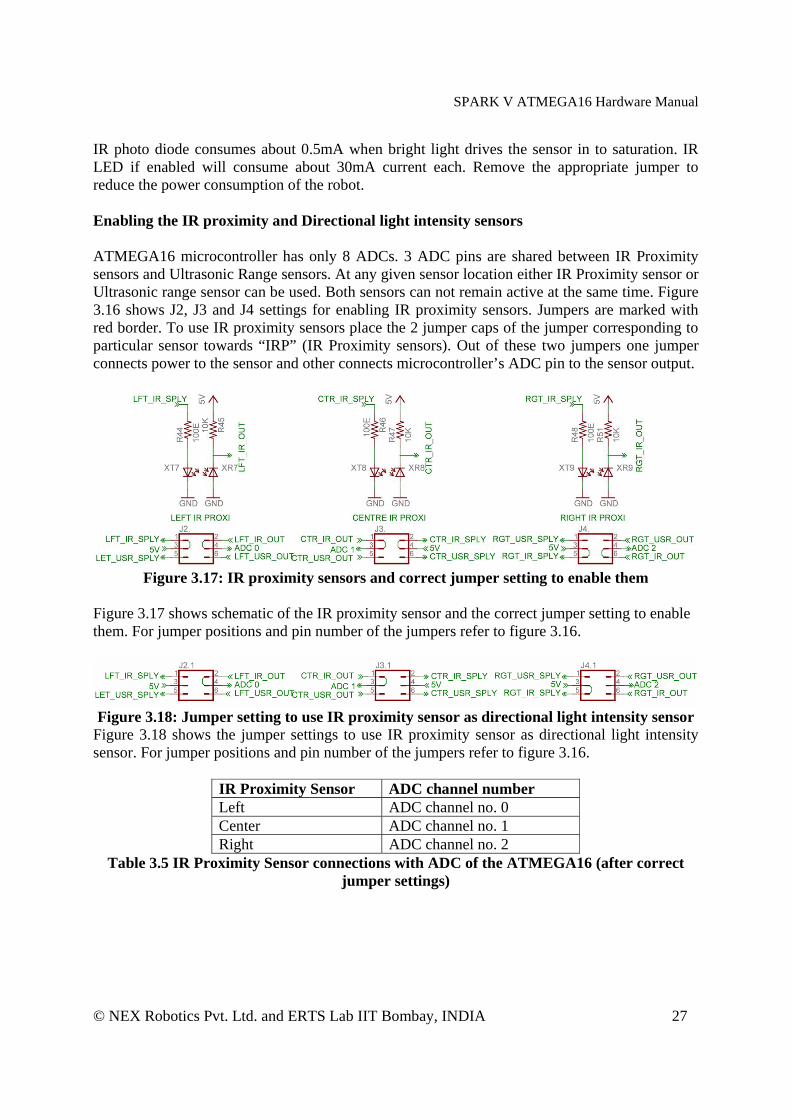
IR photo diode consumes about 0.5mA when bright light drives the sensor in to saturation. IR LED if enabled will consume about 30mA current each. Remove the appropriate jumper to reduce the power consumption of the robot. Enabling the IR proximity and Directional light intensity sensors ATMEGA16 microcontroller has only 8 ADCs. 3 ADC pins are shared between IR Proximity sensors and Ultrasonic Range sensors. At any given sensor location either IR Proximity sensor or Ultrasonic range sensor can be used. Both sensors can not remain active at the same time. Figure 3.16 shows J2, J3 and J4 settings for enabling IR proximity sensors. Jumpers are marked with red border. To use IR proximity sensors place the 2 jumper caps of the jumper corresponding to particular sensor towards “IRP” (IR Proximity sensors). Out of these two jumpers one jumper connects power to the sensor and other connects microcontroller’s ADC pin to the sensor output.
Figure 3.17: IR proximity sensors and correct jumper setting to enable them
Figure 3.17 shows schematic of the IR proximity sensor and the correct jumper setting to enable them. For jumper positions and pin number of the jumpers refer to figure 3.16.
Figure 3.18: Jumper setting to use IR proximity sensor as directional light intensity sensor
Figure 3.18 shows the jumper settings to use IR proximity sensor as directional light intensity sensor. For jumper positions and pin number of the jumpers refer to figure 3.16.
IR Proximity Sensor ADC channel number Left ADC channel no. 0 Center ADC channel no. 1 Right ADC channel no. 2
Table 3.5 IR Proximity Sensor connections with ADC of the ATMEGA16 (after correct jumper settings)
SPARK V ATMEGA16 Hardware Manual
© NEX Robotics Pvt. Ltd. and ERTS Lab IIT Bombay, INDIA 28
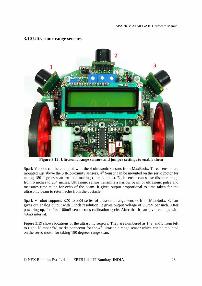
3.10 Ultrasonic range sensors
Figure 3.19: Ultrasonic range sensors and jumper settings to enable them
Spark V robot can be equipped with the 4 ultrasonic sensors from MaxBotix. Three sensors are mounted just above the 3 IR proximity sensors. 4th Sensor can be mounted on the servo motor for taking 180 degrees scan for map making (marked as 4). Each sensor can sense distance range from 6 inches to 254 inches. Ultrasonic sensor transmits a narrow beam of ultrasonic pulse and measures time taken for echo of the beam. It gives output proportional to time taken for the ultrasonic beam to return echo from the obstacle. Spark V robot supports EZ0 to EZ4 series of ultrasonic range sensors from MaxBotix. Sensor gives out analog output with 1 inch resolution. It gives output voltage of 9.8mV per inch. After powering up, for first 100mS sensor runs calibration cycle. After that it can give readings with 49mS interval. Figure 3.19 shows locations of the ultrasonic sensors. They are numbered as 1, 2, and 3 from left to right. Number “4” marks connector for the 4th ultrasonic range sensor which can be mounted on the servo motor for taking 180 degrees range scan.

SPARK V ATMEGA16 Hardware Manual
© NEX Robotics Pvt. Ltd. and ERTS Lab IIT Bombay, INDIA 29
Enabling the Ultrasonic range sensors ATMEGA16 microcontroller has only 8 ADCs. 3 ADC pins are shared between Ultrasonic Range sensors and IR Proximity sensors. At any given sensor location either IR Proximity sensor or Ultrasonic range sensor can be used. Both sensors can not remain active at the same time. Figure 3.19 shows J2, J3 and J4 settings for enabling Ultrasonic range sensors. Jumpers are marked with red border. To use Ultrasonic range sensor, place the 2 jumper caps of the jumper corresponding to particular sensor towards “URF”. Out of these two jumpers one jumper connects power to the sensor and other connects microcontroller’s ADC pin to the sensor output.
Figure 3.20: Ultrasonic range sensor daisy chaining (courtesy: MaxBotix website)
If many of the sensors transmit ultrasound simultaneously their reading will get mixed-up. In order to prevent this, all the ultrasonic sensors are connected in the daisy chain. Microcontroller sends a trigger to the first ultrasonic sensor. First sensor takes the distance reading and sends trigger to the second sensor. Second sensor follows the same process. This makes sure that at any given time only one sensor transmits ultrasound. Figure 3.20 shows sensor daisy chaining. Sensor 1’s TX pin is connected to the Sensor 2’s RX pin. In this way all 4 sensors are daisy chained. To enable the daisy chaining mode, pin “BW” of the each ultrasonic sensor is tied to Vcc. A small pulse trigger (more than 100uS) is given to the “RX” pin of the Sensor no. 1 from the microcontroller’s PD6 pin. Sensor 1 transmits ultrasonic pulse and gives out distance reading within 49mS. Sensor 1 triggers the Sensor 2 by transmitting a small pulse on its TX pin to the RX pin of the second sensor. Now Sensor 2 takes reading. In this way sensor in the daisy chain takes distance reading one at a time and triggers the next sensor connected.
Ultrasonic Range Sensor ADC channel number Left ADC channel no. 0 Center ADC channel no. 1 Right ADC channel no. 2
Table 3.6 Ultrasonic Range Sensor connections with ADC of the ATMEGA16 (after correct jumper settings)
SPARK V ATMEGA16 Hardware Manual
© NEX Robotics Pvt. Ltd. and ERTS Lab IIT Bombay, INDIA 30
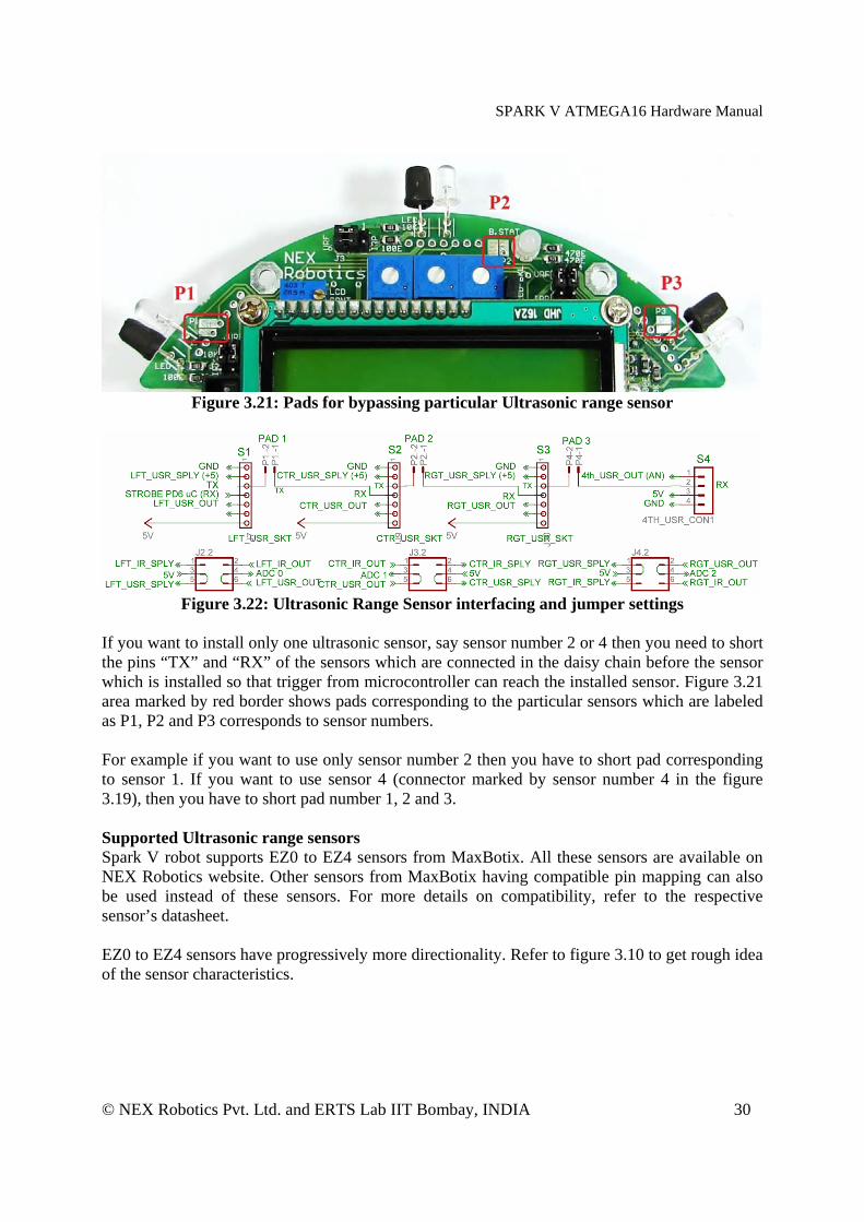
Figure 3.21: Pads for bypassing particular Ultrasonic range sensor
Figure 3.22: Ultrasonic Range Sensor interfacing and jumper settings
If you want to install only one ultrasonic sensor, say sensor number 2 or 4 then you need to short the pins “TX” and “RX” of the sensors which are connected in the daisy chain before the sensor which is installed so that trigger from microcontroller can reach the installed sensor. Figure 3.21 area marked by red border shows pads corresponding to the particular sensors which are labeled as P1, P2 and P3 corresponds to sensor numbers. For example if you want to use only sensor number 2 then you have to short pad corresponding to sensor 1. If you want to use sensor 4 (connector marked by sensor number 4 in the figure 3.19), then you have to short pad number 1, 2 and 3. Supported Ultrasonic range sensors Spark V robot supports EZ0 to EZ4 sensors from MaxBotix. All these sensors are available on NEX Robotics website. Other sensors from MaxBotix having compatible pin mapping can also be used instead of these sensors. For more details on compatibility, refer to the respective sensor’s datasheet. EZ0 to EZ4 sensors have progressively more directionality. Refer to figure 3.10 to get rough idea of the sensor characteristics.
SPARK V ATMEGA16 Hardware Manual
© NEX Robotics Pvt. Ltd. and ERTS Lab IIT Bombay, INDIA 31
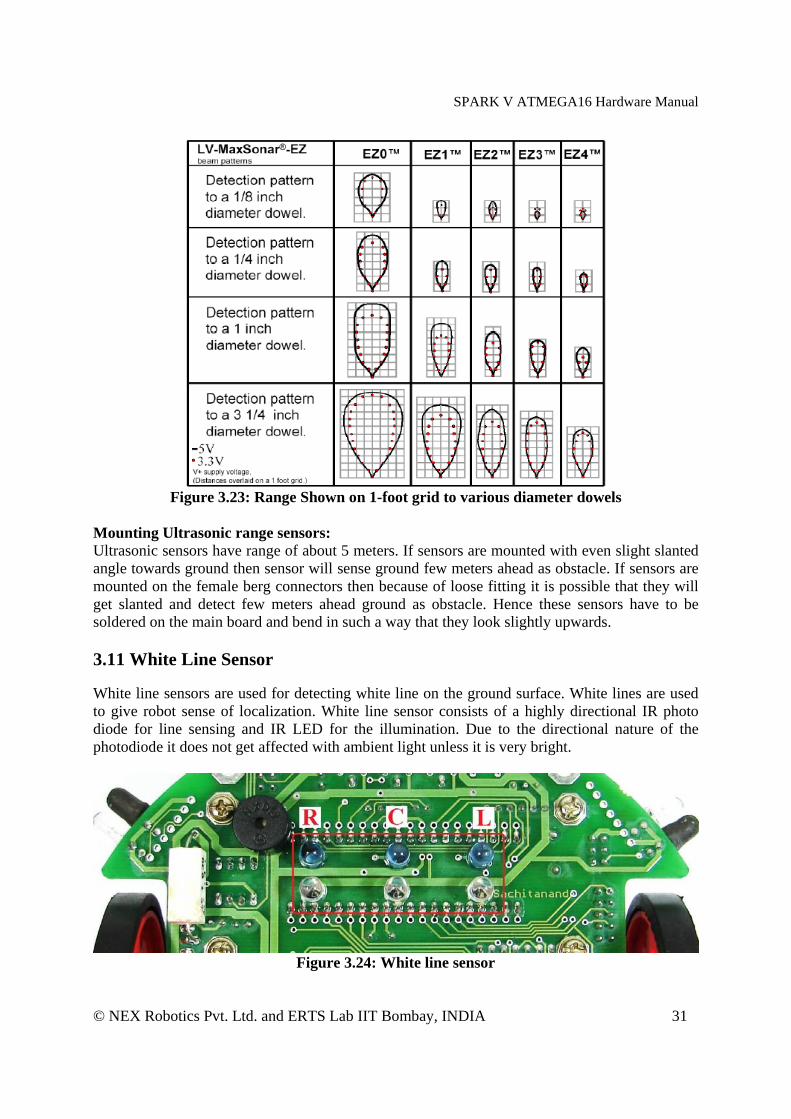
Figure 3.23: Range Shown on 1-foot grid to various diameter dowels
Mounting Ultrasonic range sensors: Ultrasonic sensors have range of about 5 meters. If sensors are mounted with even slight slanted angle towards ground then sensor will sense ground few meters ahead as obstacle. If sensors are mounted on the female berg connectors then because of loose fitting it is possible that they will get slanted and detect few meters ahead ground as obstacle. Hence these sensors have to be soldered on the main board and bend in such a way that they look slightly upwards. 3.11 White Line Sensor White line sensors are used for detecting white line on the ground surface. White lines are used to give robot sense of localization. White line sensor consists of a highly directional IR photo diode for line sensing and IR LED for the illumination. Due to the directional nature of the photodiode it does not get affected with ambient light unless it is very bright.
Figure 3.24: White line sensor

SPARK V ATMEGA16 Hardware Manual
© NEX Robotics Pvt. Ltd. and ERTS Lab IIT Bombay, INDIA 32
Figure 3.25: White Line sensor calibration potentiometers
When the robot is not on a white line, amount of light reflected is less hence less leakage current flows through the photo diode. In this case, the line sensor gives an output in the range of 3volts to 5 volts. When the sensor is on a white line, more light gets reflected resulting in considerable increase in the leakage current which causes voltage across the sensor to fall between 3 to 0.1V.
Sensor’s sensitivity to the white and dark surface can be adjusted by controlling brightness of the IR LED. This is done by adjusting potentiometer which is connected in the series of the IR LED. Figure 3.25 shows the potentiometers used for white line sensor calibration. When potentiometer is moved fully counterclockwise, IR LED’s intensity will be maximum. Robot’s sensors are calibrated for optimal performance when robot is shipped from the factory.
White line Sensor ADC channel number Left ADC channel no. 3 Center ADC channel no. 4 Right ADC channel no. 5
Table 3.7 White line sensor connections with ADC of the ATMEGA16
Note: Be very careful while selecting black surface for the line following. Black can be from ultraviolet side or from the infrared side. If black is from the infrared side then for IR light it will be like white surface as infrared black will reflect almost all the light. In such case it will be difficult for the robot to differentiate between white and black surface.
Figure 3.26: White Line Sensor

SPARK V ATMEGA16 Hardware Manual
© NEX Robotics Pvt. Ltd. and ERTS Lab IIT Bombay, INDIA 33
3.12 LCD Interfacing
Figure 3.27: LCD contrast and backlight setting
Figure 3.28: LCD interfacing with the microcontroller
Microcontroller LCD PINS Description VCC VCC Supply voltage (5V). GND GND Ground PC0 RS (Control line) Register Select PC1 R/W (Control line) READ /WRITE PC2 EN (Control Line) Enable PC4 to PC7 D4 to D7 (Data lines) Bidirectional Data Bus LED+, LED- Backlight control
Table 3.8 LCD pin mapping and functions
To interface LCD with the microcontroller in default configuration requires 3 control signals and 8 data lines. This is known as 8 bit interfacing mode which requires total 11 I/O lines. To reduce the number of I/Os required for LCD interfacing we can use 4 bit interfacing mode which requires 3 control signals with 4 data lines. In this mode upper nibble and lower nibble of commands/data set needs to be sent separately. Figure 3.28 shows LCD interfacing in 4 bit mode. The three control lines are referred to as EN, RS, and RW.

SPARK V ATMEGA16 Hardware Manual
© NEX Robotics Pvt. Ltd. and ERTS Lab IIT Bombay, INDIA 34
The EN line is called "Enable" and it is connected to PC2. This control line is used to tell the LCD that microcontroller has sent data to it or microcontroller is ready to receive data from LCD. This is indicated by a high-to-low transition on this line. To send data to the LCD, program should make sure that this line is low (0) and then set the other two control lines as required and put data on the data bus. When this is done, make EN high (1) and wait for the minimum amount of time as specified by the LCD datasheet, and end by bringing it to low (0) again.
The RS line is the "Register Select" line and it is connected to PC0. When RS is low (0), the data is treated as a command or special instruction by the LCD (such as clear screen, position cursor, etc.). When RS is high (1), the data being sent is treated as text data which should be displayed on the screen.
The RW line is the "Read/Write" control line and it is connected to PC1. When RW is low (0), the information on the data bus is being written to the LCD. When RW is high (1), the program is effectively querying (or reading from) the LCD.
The data bus is bidirectional, 4 bit wide and is connected to PC4 to PC7 of the microcontroller. The MSB bit (DB7) of data bus is also used as a Busy flag. When the Busy flag is 1, the LCD is in internal operation mode, and the next instruction will not be accepted. When RS = 0 and R/W = 1, the Busy flag is output on DB7. The next instruction must be written after ensuring that the busy flag is 0.
Figure 3.29: LCD Timing Diagram.
LCD contrast and backlight setting Contrast of the LCD can be adjusted by adjusting the potentiometer. To save power its backlight can also be turned off by removing jumper J1. For jumper and potentiometer location, refer to figure 3.27.
Figure 3.30: LCD schematics
SPARK V ATMEGA16 Hardware Manual
© NEX Robotics Pvt. Ltd. and ERTS Lab IIT Bombay, INDIA 35
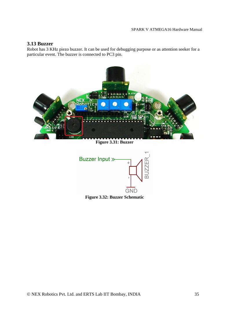
3.13 Buzzer Robot has 3 KHz piezo buzzer. It can be used for debugging purpose or as attention seeker for a particular event. The buzzer is connected to PC3 pin.
Figure 3.31: Buzzer
Figure 3.32: Buzzer Schematic
SPARK V ATMEGA16 Hardware Manual
© NEX Robotics Pvt. Ltd. and ERTS Lab IIT Bombay, INDIA 36
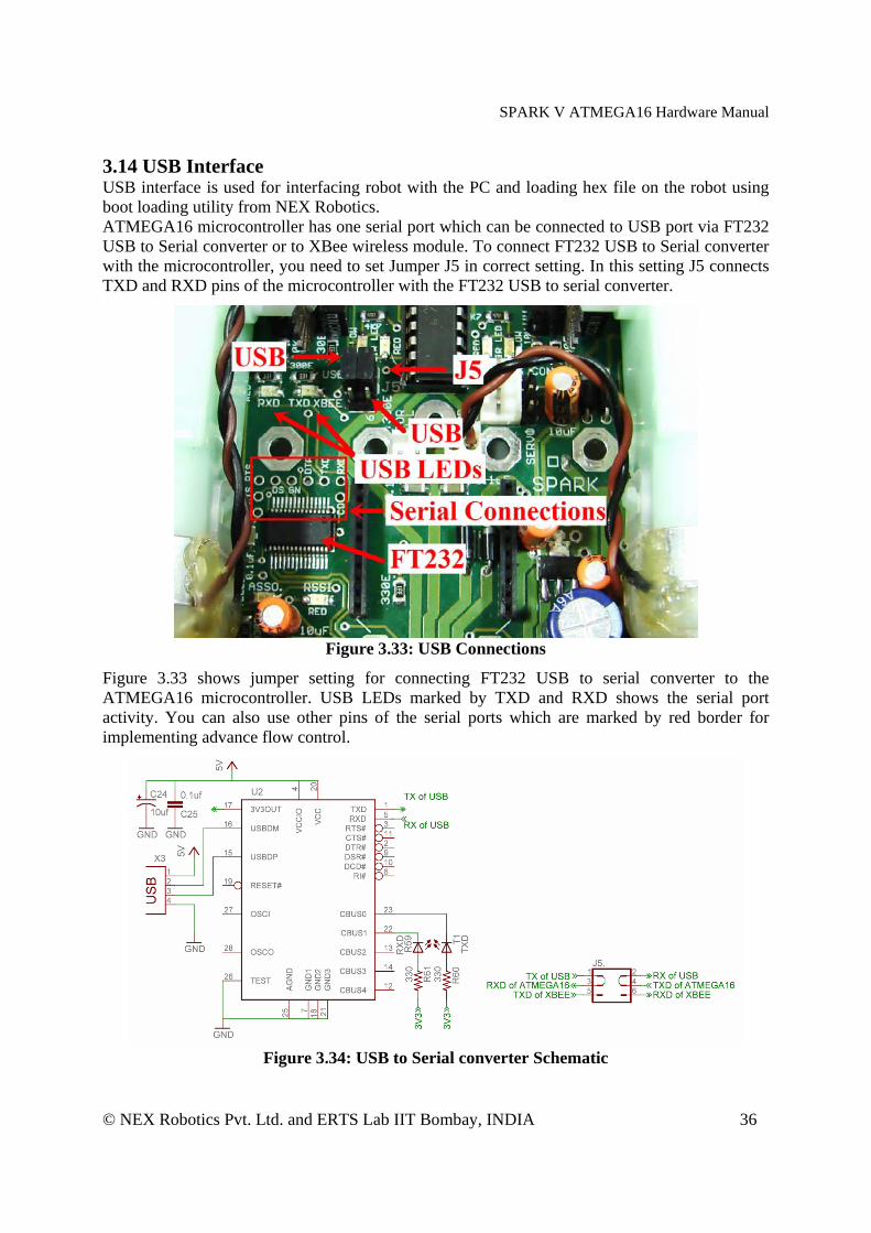
3.14 USB Interface USB interface is used for interfacing robot with the PC and loading hex file on the robot using boot loading utility from NEX Robotics. ATMEGA16 microcontroller has one serial port which can be connected to USB port via FT232 USB to Serial converter or to XBee wireless module. To connect FT232 USB to Serial converter with the microcontroller, you need to set Jumper J5 in correct setting. In this setting J5 connects TXD and RXD pins of the microcontroller with the FT232 USB to serial converter.
Figure 3.33: USB Connections
Figure 3.33 shows jumper setting for connecting FT232 USB to serial converter to the ATMEGA16 microcontroller. USB LEDs marked by TXD and RXD shows the serial port activity. You can also use other pins of the serial ports which are marked by red border for implementing advance flow control.
Figure 3.34: USB to Serial converter Schematic
SPARK V ATMEGA16 Hardware Manual
© NEX Robotics Pvt. Ltd. and ERTS Lab IIT Bombay, INDIA 37
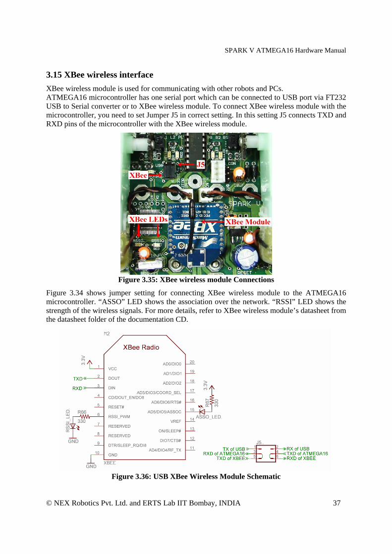
3.15 XBee wireless interface
XBee wireless module is used for communicating with other robots and PCs. ATMEGA16 microcontroller has one serial port which can be connected to USB port via FT232 USB to Serial converter or to XBee wireless module. To connect XBee wireless module with the microcontroller, you need to set Jumper J5 in correct setting. In this setting J5 connects TXD and RXD pins of the microcontroller with the XBee wireless module.
Figure 3.35: XBee wireless module Connections
Figure 3.34 shows jumper setting for connecting XBee wireless module to the ATMEGA16 microcontroller. “ASSO” LED shows the association over the network. “RSSI” LED shows the strength of the wireless signals. For more details, refer to XBee wireless module’s datasheet from the datasheet folder of the documentation CD.
Figure 3.36: USB XBee Wireless Module Schematic
SPARK V ATMEGA16 Hardware Manual
© NEX Robotics Pvt. Ltd. and ERTS Lab IIT Bombay, INDIA 38
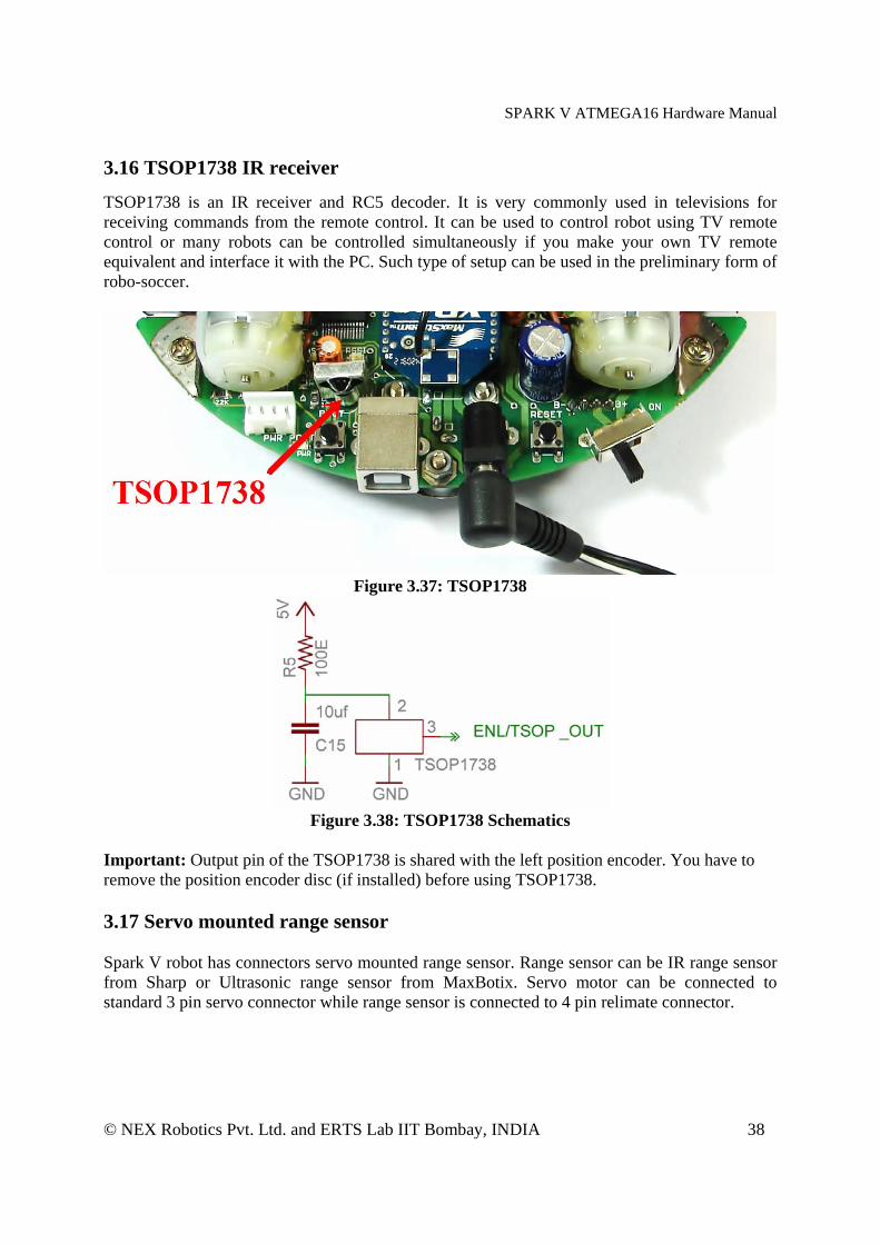
3.16 TSOP1738 IR receiver TSOP1738 is an IR receiver and RC5 decoder. It is very commonly used in televisions for receiving commands from the remote control. It can be used to control robot using TV remote control or many robots can be controlled simultaneously if you make your own TV remote equivalent and interface it with the PC. Such type of setup can be used in the preliminary form of robo-soccer.
Figure 3.37: TSOP1738
Figure 3.38: TSOP1738 Schematics
Important: Output pin of the TSOP1738 is shared with the left position encoder. You have to remove the position encoder disc (if installed) before using TSOP1738. 3.17 Servo mounted range sensor Spark V robot has connectors servo mounted range sensor. Range sensor can be IR range sensor from Sharp or Ultrasonic range sensor from MaxBotix. Servo motor can be connected to standard 3 pin servo connector while range sensor is connected to 4 pin relimate connector.

SPARK V ATMEGA16 Hardware Manual
© NEX Robotics Pvt. Ltd. and ERTS Lab IIT Bombay, INDIA 39
Figure 3.39: Servo motor and Sensor connector
Figure 3.40: Servo motor and sensor connections
3.18 Battery voltage sensing
Figure 3.41: Battery voltage sensing
SPARK V ATMEGA16 Hardware Manual
© NEX Robotics Pvt. Ltd. and ERTS Lab IIT Bombay, INDIA 40
Two registers of 22K ohms are used to scale down the battery voltage below 5V and given to the ADC6 of the microcontroller. Voltage divider network of these register will give half of the battery voltage to the ADC 6 of the microcontroller. If ADC is used with the 8 bit resolution use the following formula for getting the battery voltage level: Battery voltage = 2 x ADC 6 value of 8 bit resolution x 5V/255 Battery voltage = 2 x ADC 6 value of 10 bit resolution x 5V/1024 Here 5V / 255 and 5V/1024 give ADC resolution in 8 bit and 10 bit mode.
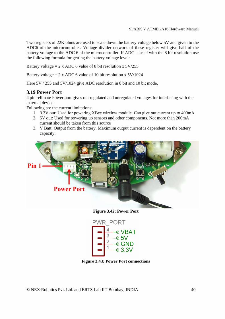
3.19 Power Port 4 pin relimate Power port gives out regulated and unregulated voltages for interfacing with the external device. Following are the current limitations:
1. 3.3V out: Used for powering XBee wireless module. Can give out current up to 400mA 2. 5V out: Used for powering up sensors and other components. Not more than 200mA
current should be taken from this source 3. V Batt: Output from the battery. Maximum output current is dependent on the battery
capacity.
Figure 3.42: Power Port
Figure 3.43: Power Port connections
SPARK V ATMEGA16 Hardware Manual
© NEX Robotics Pvt. Ltd. and ERTS Lab IIT Bombay, INDIA 41
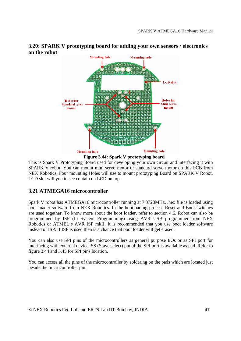
3.20: SPARK V prototyping board for adding your own sensors / electronics on the robot
Figure 3.44: Spark V prototyping board
This is Spark V Prototyping Board used for developing your own circuit and interfacing it with SPARK V robot. You can mount mini servo motor or standard servo motor on this PCB from NEX Robotics. Four mounting Holes will use to mount prototyping Board on SPARK V Robot. LCD slot will you to see contain on LCD on top. 3.21 ATMEGA16 microcontroller
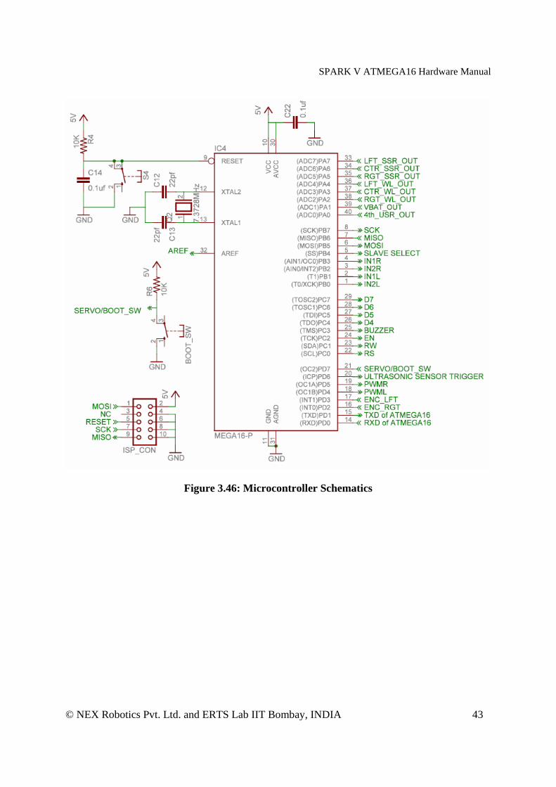
Spark V robot has ATMEGA16 microcontroller running at 7.3728MHz. .hex file is loaded using boot loader software from NEX Robotics. In the bootloading process Reset and Boot switches are used together. To know more about the boot loader, refer to section 4.6. Robot can also be programmed by ISP (In System Programming) using AVR USB programmer from NEX Robotics or ATMEL’s AVR ISP mkII. It is recommended that you use boot loader software instead of ISP. If ISP is used then is a chance that boot loader will get erased. You can also use SPI pins of the microcontrollers as general purpose I/Os or as SPI port for interfacing with external device. SS (Slave select) pin of the SPI port is available as pad. Refer to figure 3.44 and 3.45 for SPI pins location. You can access all the pins of the microcontroller by soldering on the pads which are located just beside the microcontroller pin.

SPARK V ATMEGA16 Hardware Manual
© NEX Robotics Pvt. Ltd. and ERTS Lab IIT Bombay, INDIA 42
Figure 3.45: Microcontroller on the Spark V robot
SPARK V ATMEGA16 Hardware Manual
© NEX Robotics Pvt. Ltd. and ERTS Lab IIT Bombay, INDIA 43
Figure 3.46: Microcontroller Schematics

SPARK V ATMEGA16 Hardware Manual
© NEX Robotics Pvt. Ltd. and ERTS Lab IIT Bombay, INDIA 44
3.22 Spark V Schematics

SPARK V ATMEGA16 Hardware Manual
© NEX Robotics Pvt. Ltd. and ERTS Lab IIT Bombay, INDIA 45
SPARK V ATMEGA16 Hardware Manual
© NEX Robotics Pvt. Ltd. and ERTS Lab IIT Bombay, INDIA 46
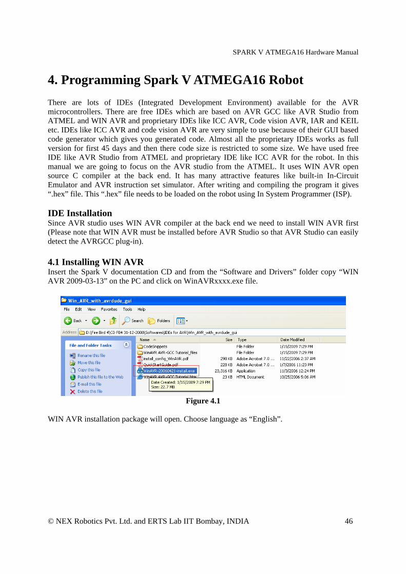
4. Programming Spark V ATMEGA16 Robot There are lots of IDEs (Integrated Development Environment) available for the AVR microcontrollers. There are free IDEs which are based on AVR GCC like AVR Studio from ATMEL and WIN AVR and proprietary IDEs like ICC AVR, Code vision AVR, IAR and KEIL etc. IDEs like ICC AVR and code vision AVR are very simple to use because of their GUI based code generator which gives you generated code. Almost all the proprietary IDEs works as full version for first 45 days and then there code size is restricted to some size. We have used free IDE like AVR Studio from ATMEL and proprietary IDE like ICC AVR for the robot. In this manual we are going to focus on the AVR studio from the ATMEL. It uses WIN AVR open source C compiler at the back end. It has many attractive features like built-in In-Circuit Emulator and AVR instruction set simulator. After writing and compiling the program it gives “.hex” file. This “.hex” file needs to be loaded on the robot using In System Programmer (ISP). IDE Installation Since AVR studio uses WIN AVR compiler at the back end we need to install WIN AVR first (Please note that WIN AVR must be installed before AVR Studio so that AVR Studio can easily detect the AVRGCC plug-in). 4.1 Installing WIN AVR Insert the Spark V documentation CD and from the “Software and Drivers” folder copy “WIN AVR 2009-03-13” on the PC and click on WinAVRxxxx.exe file.
Figure 4.1
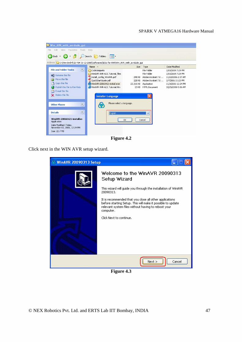
WIN AVR installation package will open. Choose language as “English”.
SPARK V ATMEGA16 Hardware Manual
© NEX Robotics Pvt. Ltd. and ERTS Lab IIT Bombay, INDIA 47
Figure 4.2
Click next in the WIN AVR setup wizard.
Figure 4.3

SPARK V ATMEGA16 Hardware Manual
© NEX Robotics Pvt. Ltd. and ERTS Lab IIT Bombay, INDIA 48
Press “I Agree” after going through license agreement.
Figure 4.4
Make sure that you select drive on which operating system is installed.
Figure 4.5
SPARK V ATMEGA16 Hardware Manual
© NEX Robotics Pvt. Ltd. and ERTS Lab IIT Bombay, INDIA 49
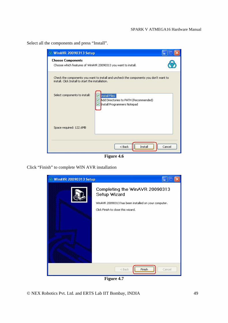
Select all the components and press “Install”.
Figure 4.6
Click “Finish” to complete WIN AVR installation
Figure 4.7
SPARK V ATMEGA16 Hardware Manual
© NEX Robotics Pvt. Ltd. and ERTS Lab IIT Bombay, INDIA 50
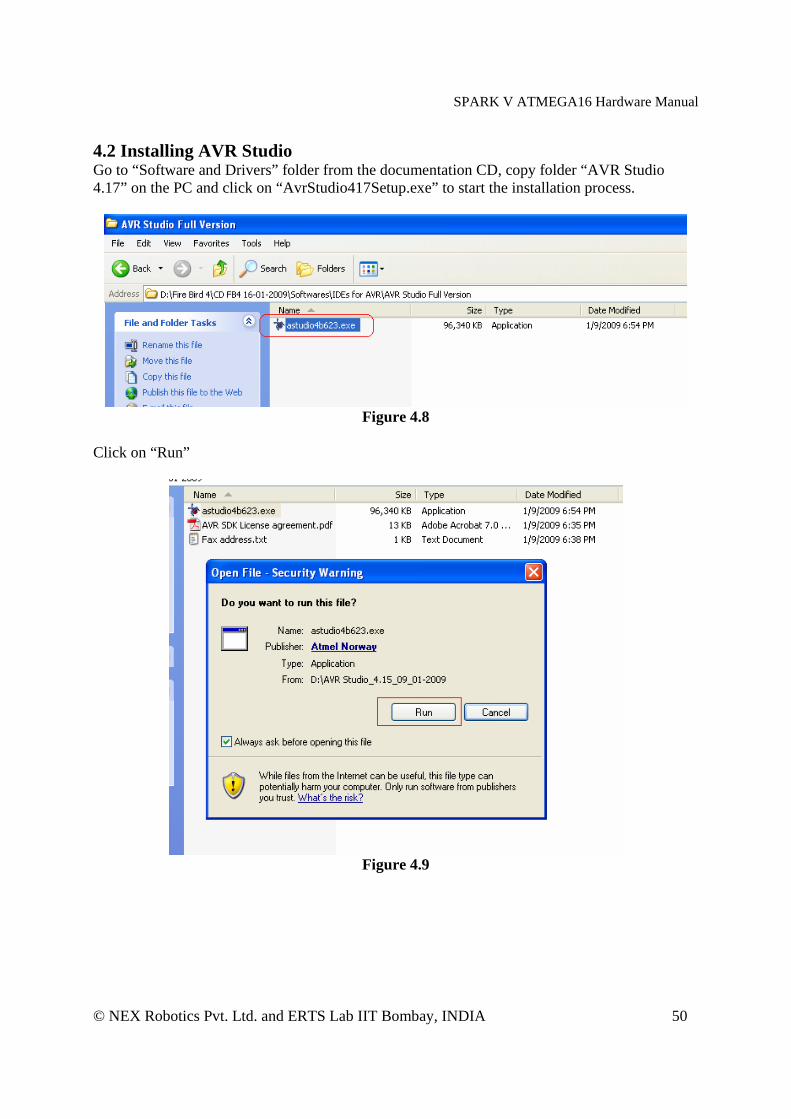
4.2 Installing AVR Studio Go to “Software and Drivers” folder from the documentation CD, copy folder “AVR Studio 4.17” on the PC and click on “AvrStudio417Setup.exe” to start the installation process.
Figure 4.8
Click on “Run”
Figure 4.9
SPARK V ATMEGA16 Hardware Manual
© NEX Robotics Pvt. Ltd. and ERTS Lab IIT Bombay, INDIA 51
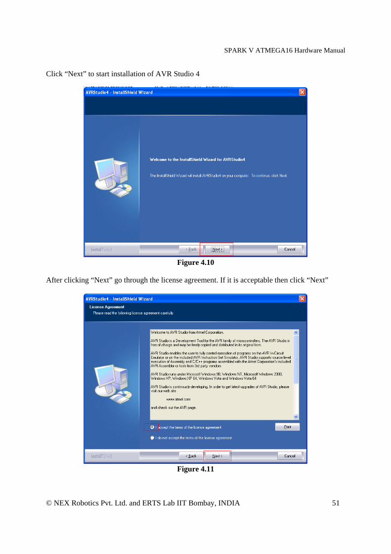
Click “Next” to start installation of AVR Studio 4
Figure 4.10
After clicking “Next” go through the license agreement. If it is acceptable then click “Next”
Figure 4.11
SPARK V ATMEGA16 Hardware Manual
© NEX Robotics Pvt. Ltd. and ERTS Lab IIT Bombay, INDIA 52
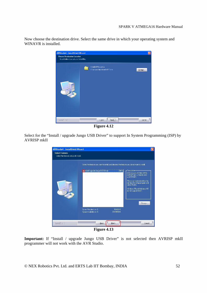
Now choose the destination drive. Select the same drive in which your operating system and WINAVR is installed.
Figure 4.12
Select for the “Install / upgrade Jungo USB Driver” to support In System Programming (ISP) by AVRISP mkII
Figure 4.13
Important: If “Install / upgrade Jungo USB Driver” is not selected then AVRISP mkII programmer will not work with the AVR Studio.

SPARK V ATMEGA16 Hardware Manual
© NEX Robotics Pvt. Ltd. and ERTS Lab IIT Bombay, INDIA 53
Click “Next” to start the installation process.
Figure 4.14
Click “Finish” to complete the installation process.
Figure 4.15

SPARK V ATMEGA16 Hardware Manual
© NEX Robotics Pvt. Ltd. and ERTS Lab IIT Bombay, INDIA 54
4.3 Setting up Project in AVR Studio AVR studio is an Integrated Development Environment (IDE) for writing and debugging AVR applications. As a code writing environment, it supports included AVR Assembler and any external AVR GCC compiler in a complete IDE environment. AVR Studio gives two main advantages:
1. Edit and debug in the same application windows. Faster error tracking. 2. Breakpoints are saved and restored between sessions, even if codes are edited.
Figure 4.16
Middle window shows current code under development. Window on the left side shows view of source files, header files, External dependencies, and other files. Right side window shows all the ports and other peripheral’s status. Bottom window is known as Build window. It shows results of the compilation, errors, HEX file size and other warning messages etc.
1. Open AVR Studio. If any project is running it can be closed by clicking on Project in the menu and select Close Project.
2. To create new project click on Project in the menu and select “New Project”.

SPARK V ATMEGA16 Hardware Manual
© NEX Robotics Pvt. Ltd. and ERTS Lab IIT Bombay, INDIA 55
Figure 4.17
3. Select Project Type as “AVR GCC”. Type project name in the “Project name” window. In this case it is “buzzer_test”. Also check on Create folder check box. This will create all the files inside the new folder. In the Location window select the place where would like to store your project folder and then click “Next”.
Figure 4.18
SPARK V ATMEGA16 Hardware Manual
© NEX Robotics Pvt. Ltd. and ERTS Lab IIT Bombay, INDIA 56
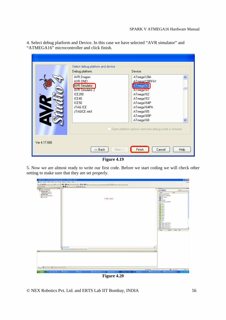
4. Select debug platform and Device. In this case we have selected “AVR simulator” and “ATMEGA16” microcontroller and click finish.
Figure 4.19
5. Now we are almost ready to write our first code. Before we start coding we will check other setting to make sure that they are set properly.
Figure 4.20

SPARK V ATMEGA16 Hardware Manual
© NEX Robotics Pvt. Ltd. and ERTS Lab IIT Bombay, INDIA 57
6. Open Project menu and click on the Configuration option.
Figure 4.21
7. In the Project Option “General” tab will open. Select device as “ATMEGA16” and frequency (Crystal Frequency) as 7.3728MHz i.e. 7372800Hz. Set the optimization level be at “-O0”.
Figure 4.22
Selecting proper optimization options “Optimization” option defines the optimization level for all files. Higher optimization levels will produce code that is harder to debug. Stack variables may change location, or be optimized away, and source level debugging may "skip" statements because they too have been optimized away. The levels of optimization are:
SPARK V ATMEGA16 Hardware Manual
© NEX Robotics Pvt. Ltd. and ERTS Lab IIT Bombay, INDIA 58
• No optimization. This is the same as not specifying any optimization. • -01 Optimize. Reduces code size and execution time without performing any
optimizations that take a great deal of compilation time. • -O2 Optimize even more. avr-gcc performs almost all optimizations that don't involve
a space-time tradeoff. • -O3 Optimize yet more. This level performs all optimizations at -O2 along with -
finline-functions and -frename-registers. • -Os Optimize for size. Enables all -O2 optimizations that don't increase code size. It
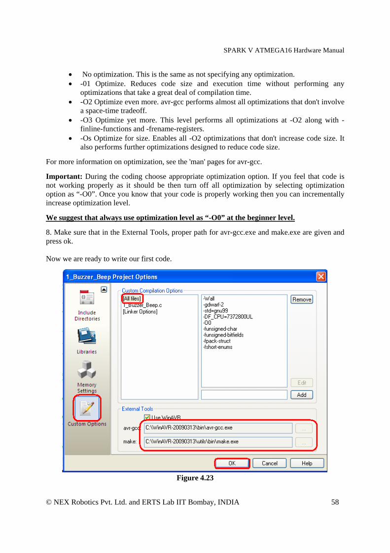
also performs further optimizations designed to reduce code size. For more information on optimization, see the 'man' pages for avr-gcc. Important: During the coding choose appropriate optimization option. If you feel that code is not working properly as it should be then turn off all optimization by selecting optimization option as “-O0”. Once you know that your code is properly working then you can incrementally increase optimization level. We suggest that always use optimization level as “-O0” at the beginner level. 8. Make sure that in the External Tools, proper path for avr-gcc.exe and make.exe are given and press ok. Now we are ready to write our first code.
Figure 4.23
SPARK V ATMEGA16 Hardware Manual
© NEX Robotics Pvt. Ltd. and ERTS Lab IIT Bombay, INDIA 59
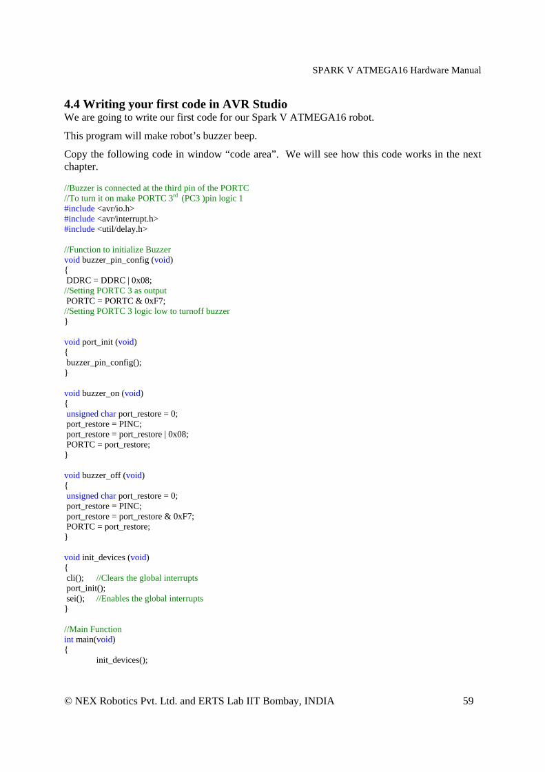
4.4 Writing your first code in AVR Studio We are going to write our first code for our Spark V ATMEGA16 robot.
This program will make robot’s buzzer beep.
Copy the following code in window “code area”. We will see how this code works in the next chapter. //Buzzer is connected at the third pin of the PORTC //To turn it on make PORTC 3rd (PC3 )pin logic 1 #include <avr/io.h> #include <avr/interrupt.h> #include <util/delay.h> //Function to initialize Buzzer void buzzer_pin_config (void) { DDRC = DDRC | 0x08; //Setting PORTC 3 as output PORTC = PORTC & 0xF7; //Setting PORTC 3 logic low to turnoff buzzer } void port_init (void) { buzzer_pin_config(); } void buzzer_on (void) { unsigned char port_restore = 0; port_restore = PINC; port_restore = port_restore | 0x08; PORTC = port_restore; } void buzzer_off (void) { unsigned char port_restore = 0; port_restore = PINC; port_restore = port_restore & 0xF7; PORTC = port_restore; } void init_devices (void) { cli(); //Clears the global interrupts port_init(); sei(); //Enables the global interrupts } //Main Function int main(void) { init_devices();
SPARK V ATMEGA16 Hardware Manual
© NEX Robotics Pvt. Ltd. and ERTS Lab IIT Bombay, INDIA 60
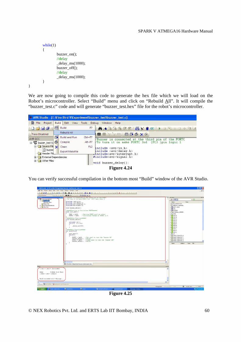
while(1) { buzzer_on(); //delay
_delay_ms(1000); buzzer_off();
//delay _delay_ms(1000);
} } We are now going to compile this code to generate the hex file which we will load on the Robot’s microcontroller. Select “Build” menu and click on “Rebuild All”. It will compile the “buzzer_test.c” code and will generate “buzzer_test.hex” file for the robot’s microcontroller.
Figure 4.24
You can verify successful compilation in the bottom most “Build” window of the AVR Studio.
Figure 4.25

SPARK V ATMEGA16 Hardware Manual
© NEX Robotics Pvt. Ltd. and ERTS Lab IIT Bombay, INDIA 61
You can also verify that “buzzer_test.hex” file is generated in the “default” folder inside the folder you have selected. 4.5 Debugging the code in AVR studio After successful compilation of the code we can debug the code by AVR Debugger provided by AVRStudio. Here is the illustration of debugging of code given in Exp1 (buzzer ON-OFF folder). Click on Debug tab in the menu and click on “Start Debugging”.
Figure 4.26
Now debugging mode is started and an arrow is visible at the first line of our main function from where the debugging will start.
Figure 4.27
SPARK V ATMEGA16 Hardware Manual
© NEX Robotics Pvt. Ltd. and ERTS Lab IIT Bombay, INDIA 62
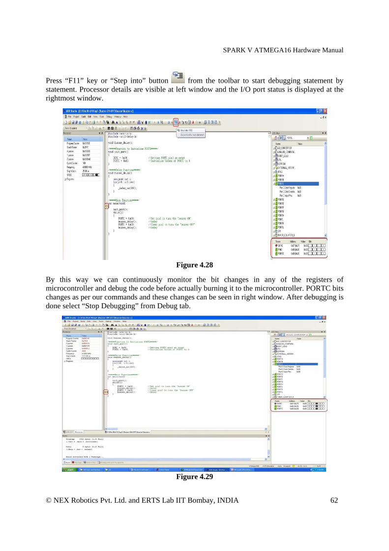
Press “F11” key or “Step into” button from the toolbar to start debugging statement by statement. Processor details are visible at left window and the I/O port status is displayed at the rightmost window.
Figure 4.28
By this way we can continuously monitor the bit changes in any of the registers of microcontroller and debug the code before actually burning it to the microcontroller. PORTC bits changes as per our commands and these changes can be seen in right window. After debugging is done select “Stop Debugging” from Debug tab.
Figure 4.29

SPARK V ATMEGA16 Hardware Manual
© NEX Robotics Pvt. Ltd. and ERTS Lab IIT Bombay, INDIA 63
4.6 Loading your code on robot using AVR Boot loader from NEX Robotics
All AVR microcontrollers can be programmed using In System Programming (ISP), external programmer or using boot loader. Advantage with the boot loader is that you don’t need any external hardware to load the .hex file on the microcontroller.
4.6.1 Boot loader operating principle
If Bootloader firmware is loaded on the microcontroller then it can be programmed directly via serial port or USB (using USB to Serial converter) using PC. In the boot loading method a small piece of code is loaded on the microcontroller in the configurable boot memory section. When signaled using external switch while resetting the microcontroller it gets active and waits for communication from the PC. Bootloader software from NEX Robotics which is installed on the PC communicates with the microcontroller. Boot loader software loads the .hex file on the microcontroller. After the boot loading process is complete, newly loaded code can be executed by pressing reset. Once the code is loaded on the microcontroller UART is free and can be used for other applications. Bootloader get invoked only if boot switch is kept pressed while microcontroller is reset using reset switch.
Note: Bootloader code is loaded on the ATMEGA16 of the Spark V robot using ISP programmer. It is recommended that you only use Bootloader for the robot. If you use ISP programmer with the robot then boot section code might get erased and robot will no longer support boot loading.
4.6.2 Jumper settings for the boot loading
ATMEGA16 has one serial port. In Spark V it can be switched between USB and XBee wireless module by using jumper J5. For serial interfacing FT232 USB to Serial converter is used.
Bootloading is done via USB Port. Figure 4.30 shows the correct jumper settings of J5 to connect USB port to the ATMEGA16 via FT232 USB to serial converter. Figure 4.30 shows the correct jumper settings for the boot loading.
Figure 4.30: Jumper setting for connecting USB port
SPARK V ATMEGA16 Hardware Manual
© NEX Robotics Pvt. Ltd. and ERTS Lab IIT Bombay, INDIA 64
4.6.3 Installing FT232 USB to Serial converter drivers Before using USB port we need to install the driver software for FT232 USB to serial converter. The software is located in the “Software and Drivers \ CDM 2.06.00 WHQL Certified” folder. provided in the SPARK V CD or can also be downloaded from the NEX Robotics’ website.
Important: Make sure that jumper is configured to enable USB communication. Jumpers on J5 should be in the position.
Steps to install the drivers for USB to serial converter:
Step 1: Copy the driver installation folder on your PC from “Software and Drivers \ CDM 2.06.00 WHQL Certified” Folder in the CD.
Step 2: Connect the USB to serial converter cable between robot and the PC
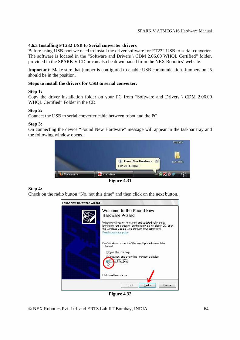
Step 3: On connecting the device “Found New Hardware” message will appear in the taskbar tray and the following window opens.
Figure 4.31
Step 4: Check on the radio button “No, not this time” and then click on the next button.
Figure 4.32

SPARK V ATMEGA16 Hardware Manual
© NEX Robotics Pvt. Ltd. and ERTS Lab IIT Bombay, INDIA 65
The following window will appear.
Figure 4.33
Select the second option manually to install the drivers and click on next button. Step 5: Now check the second option and set the location of folder containing drivers E.g.(C:\CDM 2.06.00 WHQL Certified).
Figure 4.34
SPARK V ATMEGA16 Hardware Manual
© NEX Robotics Pvt. Ltd. and ERTS Lab IIT Bombay, INDIA 66
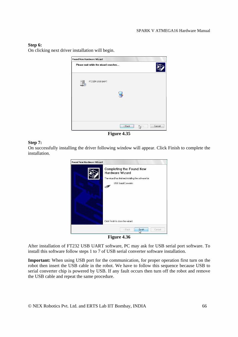
Step 6: On clicking next driver installation will begin.
Figure 4.35
Step 7: On successfully installing the driver following window will appear. Click Finish to complete the installation.
Figure 4.36
After installation of FT232 USB UART software, PC may ask for USB serial port software. To install this software follow steps 1 to 7 of USB serial converter software installation. Important: When using USB port for the communication, for proper operation first turn on the robot then insert the USB cable in the robot. We have to follow this sequence because USB to serial converter chip is powered by USB. If any fault occurs then turn off the robot and remove the USB cable and repeat the same procedure.
SPARK V ATMEGA16 Hardware Manual
© NEX Robotics Pvt. Ltd. and ERTS Lab IIT Bombay, INDIA 67
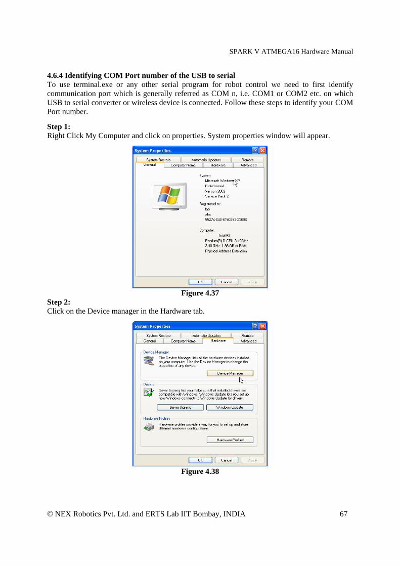
4.6.4 Identifying COM Port number of the USB to serial To use terminal.exe or any other serial program for robot control we need to first identify communication port which is generally referred as COM n, i.e. COM1 or COM2 etc. on which USB to serial converter or wireless device is connected. Follow these steps to identify your COM Port number. Step 1: Right Click My Computer and click on properties. System properties window will appear.
Figure 4.37
Step 2: Click on the Device manager in the Hardware tab.
Figure 4.38

SPARK V ATMEGA16 Hardware Manual
© NEX Robotics Pvt. Ltd. and ERTS Lab IIT Bombay, INDIA 68
Step 3: Expand Ports (Com & LPT) tree. COM Port number is mentioned in the parenthesis next to USB Serial Port.
Figure 4.39
Step 4: If the COM port number is greater than 10 Terminal will not be able to detect it. To resolve this problem, change the port number by right clicking on “USB serial Port” and select properties.
Figure 4.40
In the Port settings tab click on the “Advanced” button, the following window will appear.

SPARK V ATMEGA16 Hardware Manual
© NEX Robotics Pvt. Ltd. and ERTS Lab IIT Bombay, INDIA 69
Figure 4.41
You can change the COM port number by clicking on the Com Port number drop down list and select the appropriate number. Make sure the new COM port is not being used by any other device. 4.6.5 Installing and using Bootloader GUI Insert the Spark V documentation CD and from the “Software and Drivers” folder copy “AVR Bootloader” on the PC and click on “setup” application file.
Figure 4.42
It will pop-up with the “AVR Bootloader Setup wizard”
SPARK V ATMEGA16 Hardware Manual
© NEX Robotics Pvt. Ltd. and ERTS Lab IIT Bombay, INDIA 70
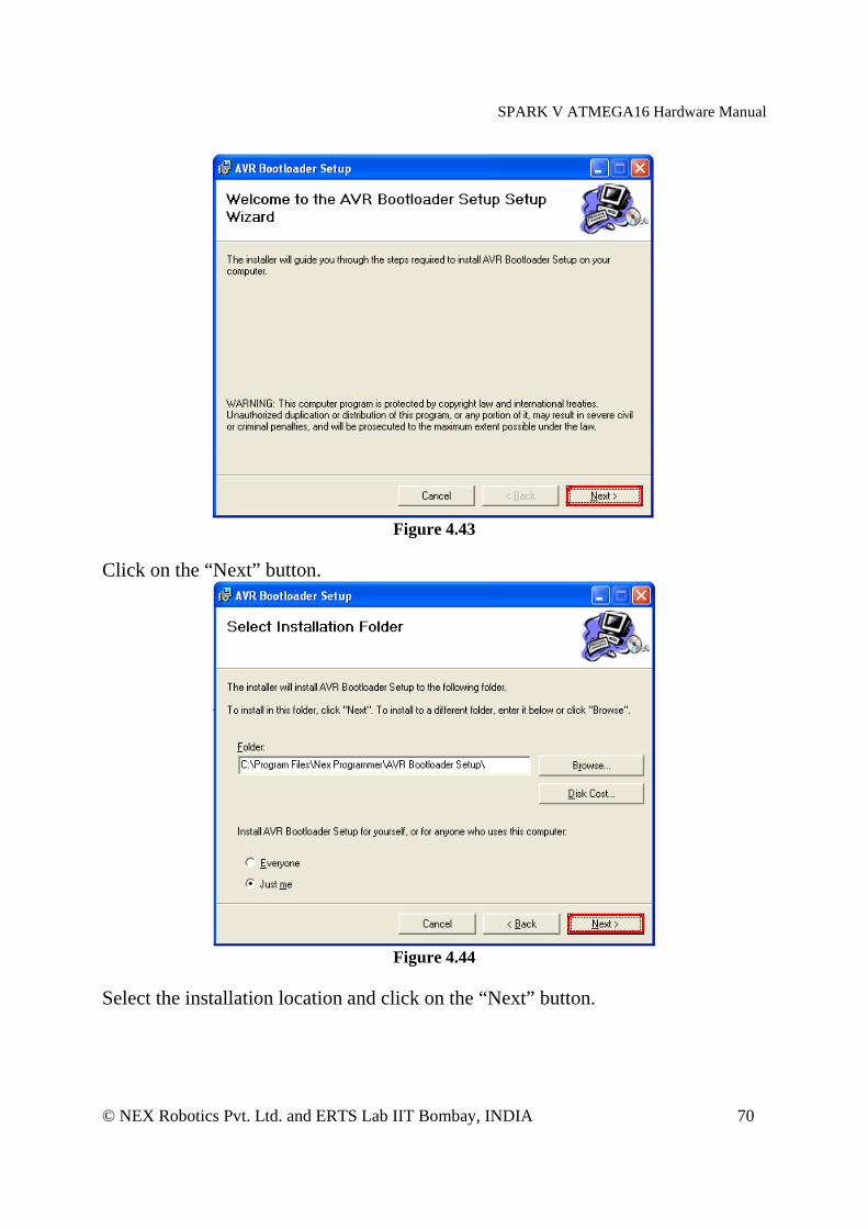
Figure 4.43
Click on the “Next” button.
Figure 4.44
Select the installation location and click on the “Next” button.

SPARK V ATMEGA16 Hardware Manual
© NEX Robotics Pvt. Ltd. and ERTS Lab IIT Bombay, INDIA 71
Figure 4.45
Click on the close button and the installation is complete. Now you can use the Boot loader. 4.6.6 Using Boot loader Step1: Turn on the robot. Step2: Connect a USB cable between the USB port on your PC and the USB connector on SPARKV Robot. Step3: Enter in to boot load mode by keeping the BOOT switch pressed and then press and release RESET switch. Release BOOT switch after releasing reset. Step4: To start the Bootloader you can click on the desktop icon which is created while installation or you can open it by going to “Start” menu using following path.
"C:\Program Files\Nex Programmer\AVR Bootloader Setup\"
SPARK V ATMEGA16 Hardware Manual
© NEX Robotics Pvt. Ltd. and ERTS Lab IIT Bombay, INDIA 72
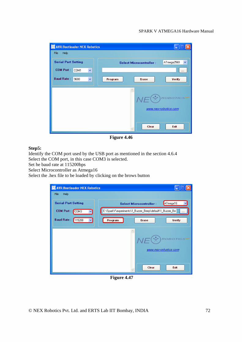
Figure 4.46
Step5: Identify the COM port used by the USB port as mentioned in the section 4.6.4 Select the COM port, in this case COM3 is selected. Set he baud rate at 115200bps Select Microcontroller as Atmega16 Select the .hex file to be loaded by clicking on the brows button
Figure 4.47
SPARK V ATMEGA16 Hardware Manual
© NEX Robotics Pvt. Ltd. and ERTS Lab IIT Bombay, INDIA 73
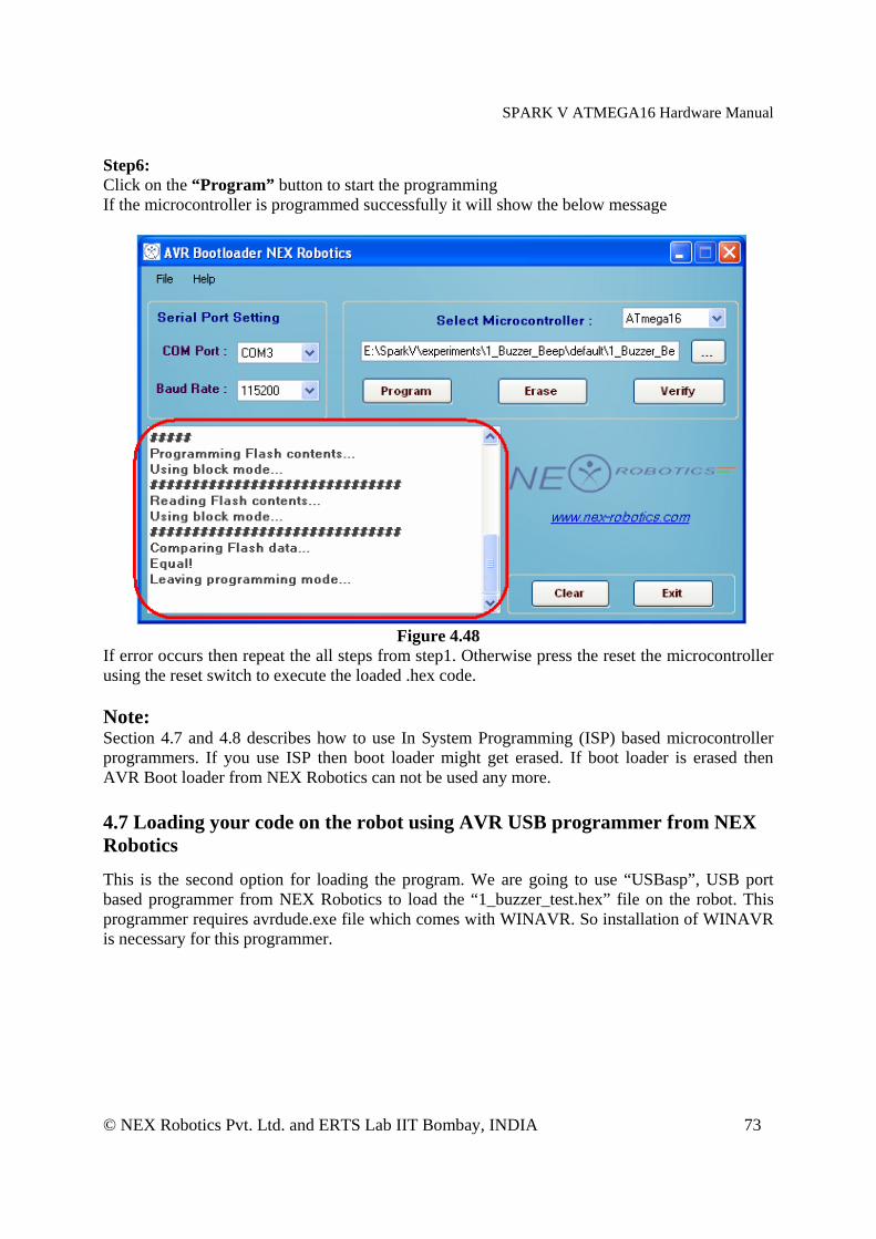
Step6: Click on the “Program” button to start the programming If the microcontroller is programmed successfully it will show the below message
Figure 4.48
If error occurs then repeat the all steps from step1. Otherwise press the reset the microcontroller using the reset switch to execute the loaded .hex code. Note: Section 4.7 and 4.8 describes how to use In System Programming (ISP) based microcontroller programmers. If you use ISP then boot loader might get erased. If boot loader is erased then AVR Boot loader from NEX Robotics can not be used any more. 4.7 Loading your code on the robot using AVR USB programmer from NEX Robotics This is the second option for loading the program. We are going to use “USBasp”, USB port based programmer from NEX Robotics to load the “1_buzzer_test.hex” file on the robot. This programmer requires avrdude.exe file which comes with WINAVR. So installation of WINAVR is necessary for this programmer.
SPARK V ATMEGA16 Hardware Manual
© NEX Robotics Pvt. Ltd. and ERTS Lab IIT Bombay, INDIA 74
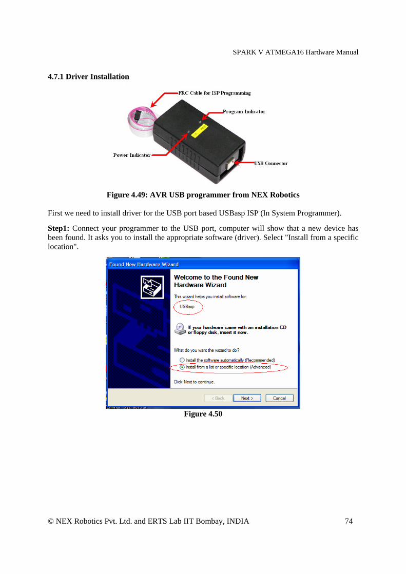
4.7.1 Driver Installation
Figure 4.49: AVR USB programmer from NEX Robotics
First we need to install driver for the USB port based USBasp ISP (In System Programmer). Step1: Connect your programmer to the USB port, computer will show that a new device has been found. It asks you to install the appropriate software (driver). Select "Install from a specific location".
Figure 4.50
SPARK V ATMEGA16 Hardware Manual
© NEX Robotics Pvt. Ltd. and ERTS Lab IIT Bombay, INDIA 75
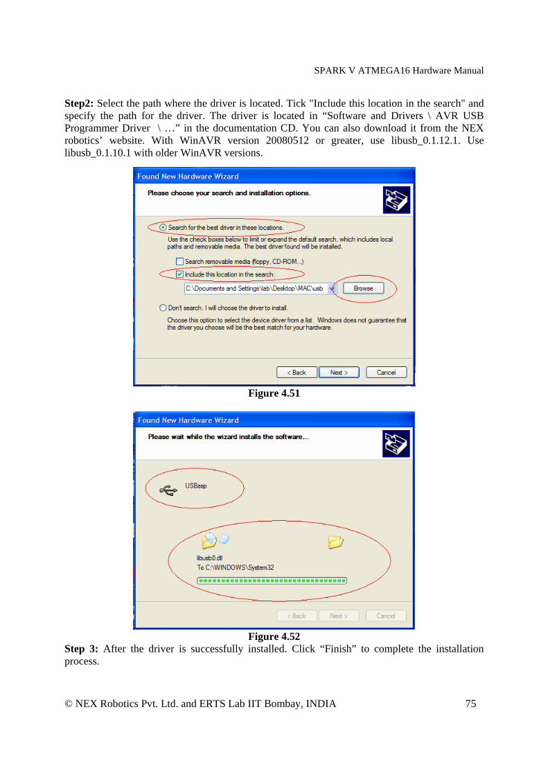
Step2: Select the path where the driver is located. Tick "Include this location in the search" and specify the path for the driver. The driver is located in “Software and Drivers \ AVR USB Programmer Driver \ …” in the documentation CD. You can also download it from the NEX robotics’ website. With WinAVR version 20080512 or greater, use libusb_0.1.12.1. Use libusb_0.1.10.1 with older WinAVR versions.
Figure 4.51
Figure 4.52
Step 3: After the driver is successfully installed. Click “Finish” to complete the installation process.
SPARK V ATMEGA16 Hardware Manual
© NEX Robotics Pvt. Ltd. and ERTS Lab IIT Bombay, INDIA 76
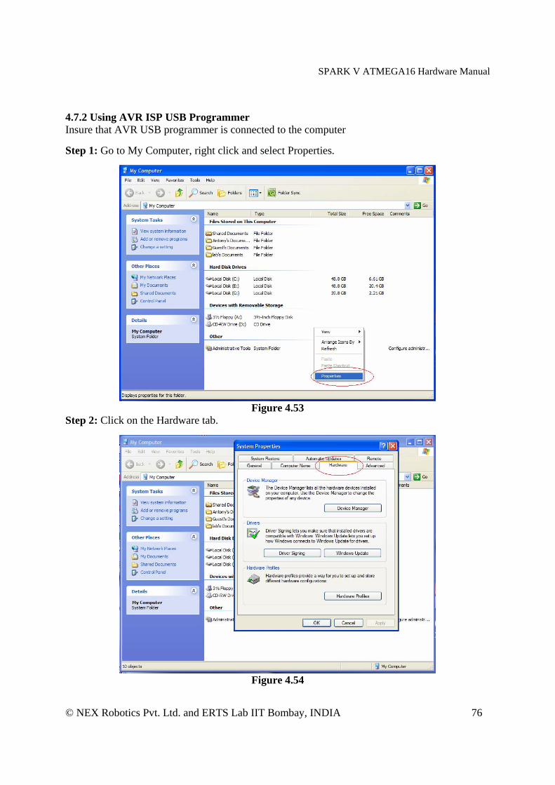
4.7.2 Using AVR ISP USB Programmer Insure that AVR USB programmer is connected to the computer Step 1: Go to My Computer, right click and select Properties.
Figure 4.53
Step 2: Click on the Hardware tab.
Figure 4.54

SPARK V ATMEGA16 Hardware Manual
© NEX Robotics Pvt. Ltd. and ERTS Lab IIT Bombay, INDIA 77
Step 3: Click Device Manager.
Figure 4.55
Step 4: Verify that an icon called LibUSB-Win32 Devices with USBasp appears in it.
Figure 4.56
SPARK V ATMEGA16 Hardware Manual
© NEX Robotics Pvt. Ltd. and ERTS Lab IIT Bombay, INDIA 78
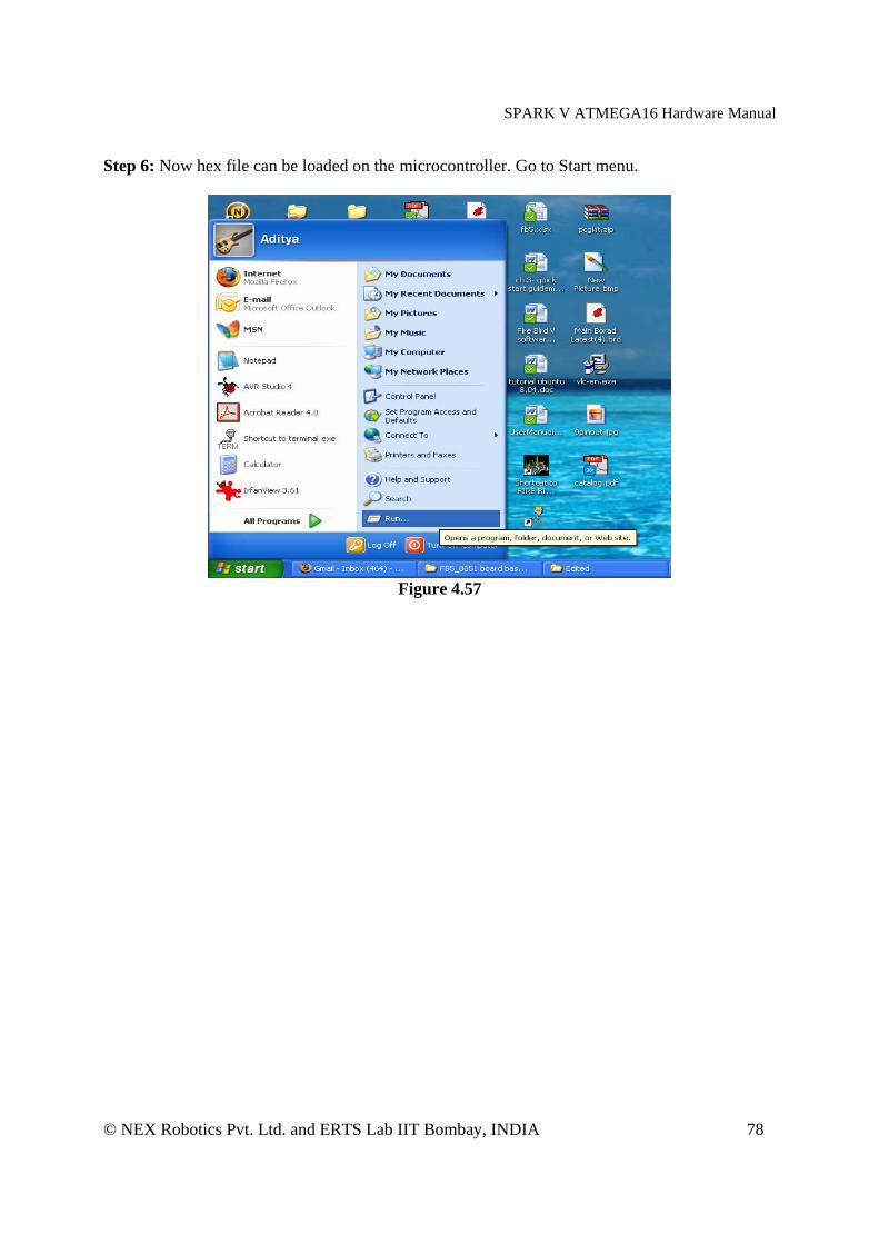
Step 6: Now hex file can be loaded on the microcontroller. Go to Start menu.
Figure 4.57
SPARK V ATMEGA16 Hardware Manual
© NEX Robotics Pvt. Ltd. and ERTS Lab IIT Bombay, INDIA 79
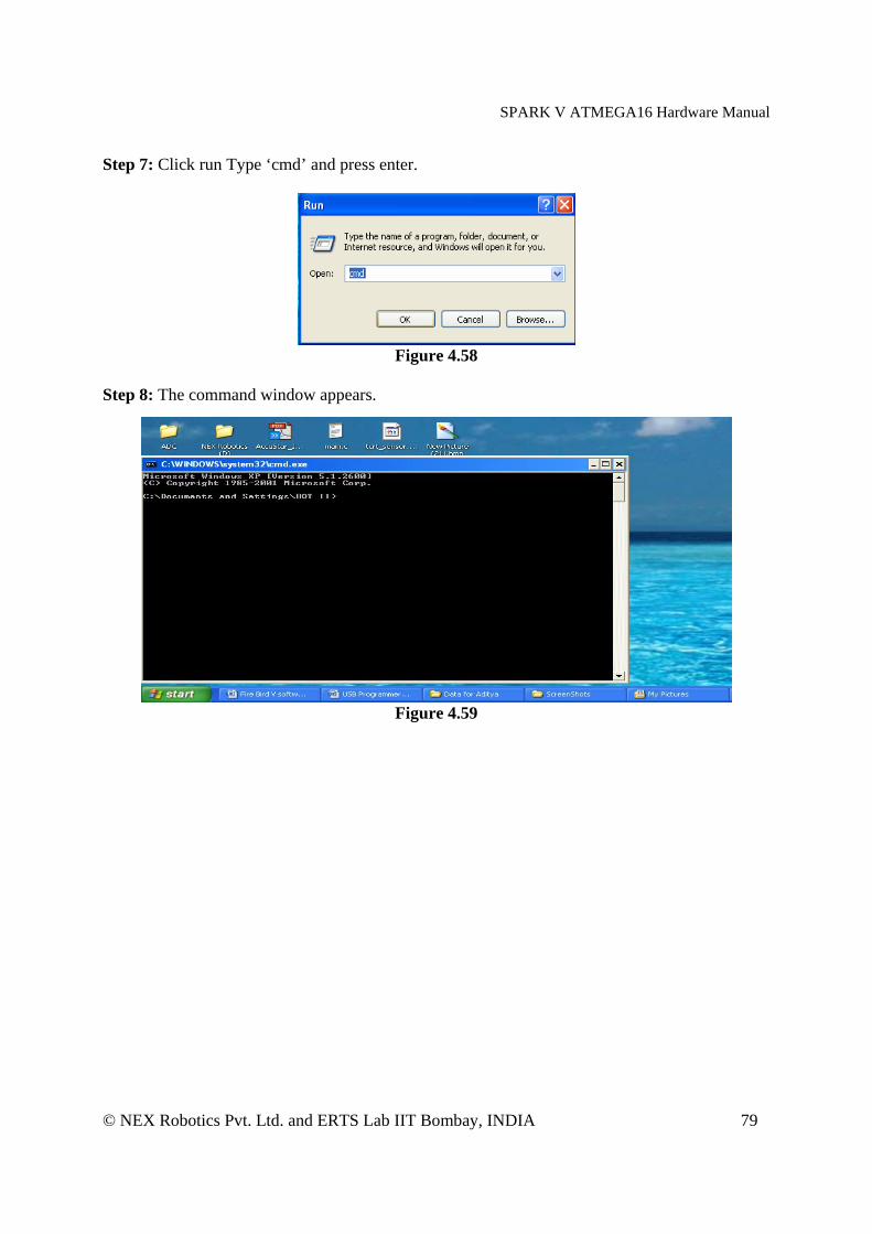
Step 7: Click run Type ‘cmd’ and press enter.
Figure 4.58
Step 8: The command window appears.
Figure 4.59
SPARK V ATMEGA16 Hardware Manual
© NEX Robotics Pvt. Ltd. and ERTS Lab IIT Bombay, INDIA 80
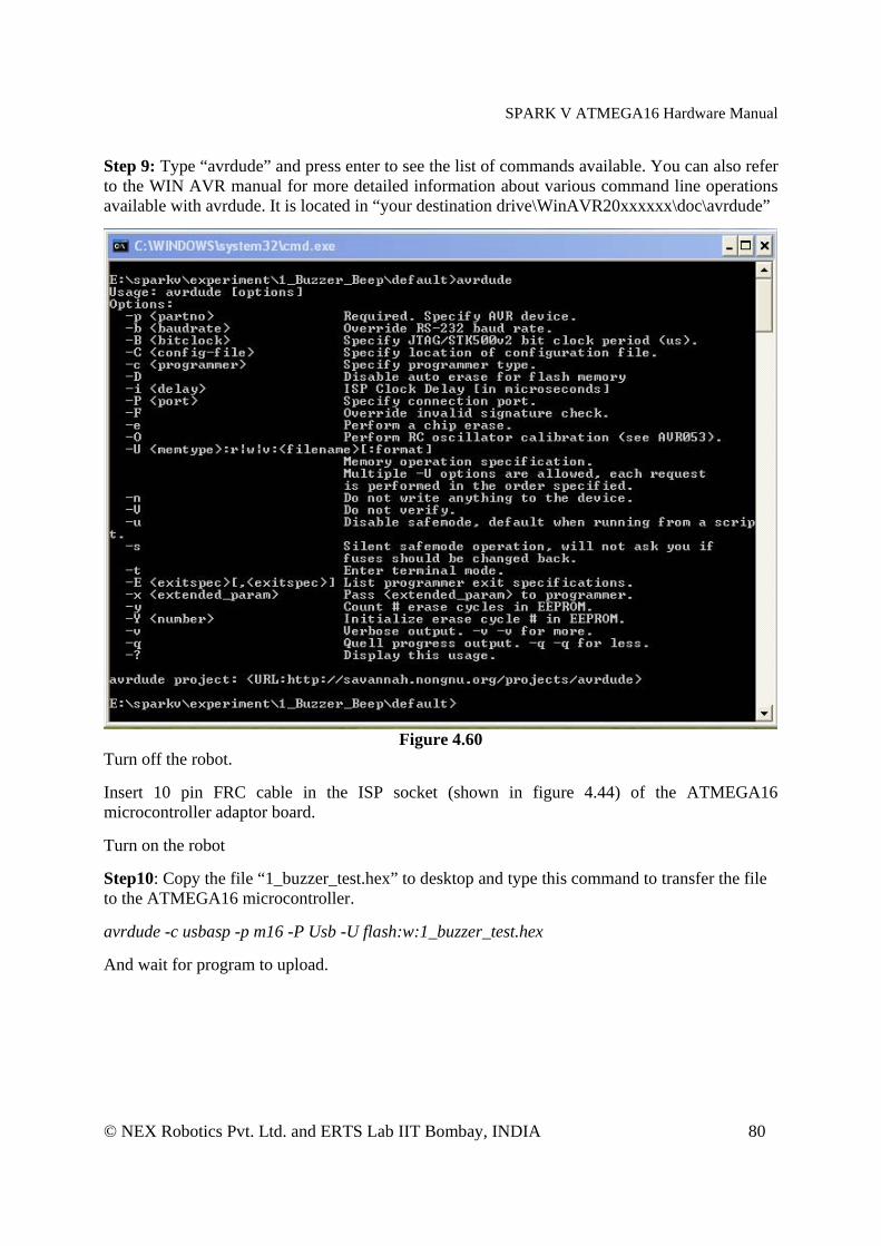
Step 9: Type “avrdude” and press enter to see the list of commands available. You can also refer to the WIN AVR manual for more detailed information about various command line operations available with avrdude. It is located in “your destination drive\WinAVR20xxxxxx\doc\avrdude”
Figure 4.60
Turn off the robot. Insert 10 pin FRC cable in the ISP socket (shown in figure 4.44) of the ATMEGA16 microcontroller adaptor board. Turn on the robot Step10: Copy the file “1_buzzer_test.hex” to desktop and type this command to transfer the file to the ATMEGA16 microcontroller. avrdude -c usbasp -p m16 -P Usb -U flash:w:1_buzzer_test.hex And wait for program to upload.
SPARK V ATMEGA16 Hardware Manual
© NEX Robotics Pvt. Ltd. and ERTS Lab IIT Bombay, INDIA 81
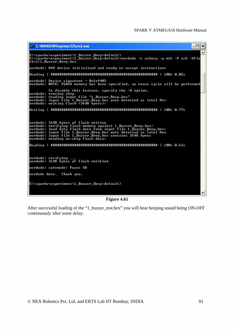
Figure 4.61
After successful loading of the “1_buzzer_test.hex” you will hear beeping sound being ON-OFF continuously after some delay.
SPARK V ATMEGA16 Hardware Manual
© NEX Robotics Pvt. Ltd. and ERTS Lab IIT Bombay, INDIA 82
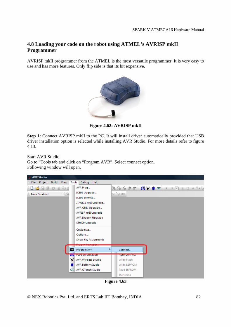
4.8 Loading your code on the robot using ATMEL’s AVRISP mkII Programmer AVRISP mkII programmer from the ATMEL is the most versatile programmer. It is very easy to use and has more features. Only flip side is that its bit expensive.
Figure 4.62: AVRISP mkII
Step 1: Connect AVRISP mkII to the PC. It will install driver automatically provided that USB driver installation option is selected while installing AVR Studio. For more details refer to figure 4.13. Start AVR Studio Go to “Tools tab and click on “Program AVR”. Select connect option. Following window will open.
Figure 4.63
SPARK V ATMEGA16 Hardware Manual
© NEX Robotics Pvt. Ltd. and ERTS Lab IIT Bombay, INDIA 83
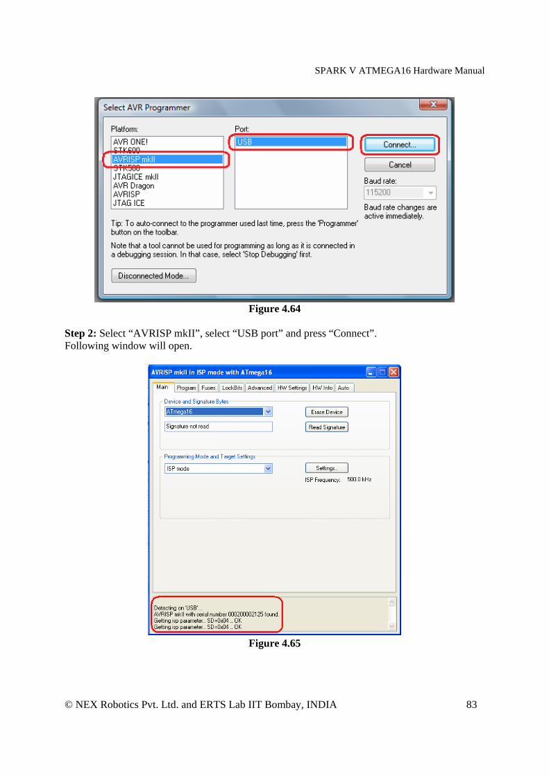
Figure 4.64
Step 2: Select “AVRISP mkII”, select “USB port” and press “Connect”. Following window will open.
Figure 4.65

SPARK V ATMEGA16 Hardware Manual
© NEX Robotics Pvt. Ltd. and ERTS Lab IIT Bombay, INDIA 84
AVRISP mkII use 6pin FRC connector for ISP while Spark V robot uses 10 pin FRC connector for programming. We need to use AVR ISP adaptor to convert 6 pin to 10 pin connector which is available on NEX Robotics website. It comes free with the AVRISP mkII programmer if it is purchased from NEX Robotics website. Step 3: Connect AVR ISP adaptor between robot and AVRISP mkII. Insert 10pin FRC connector in the Spark V ATMEGA16 robot and turn on the power.
Figure 4.66
Step 4: Go to Main tab Select “ATMEGA16” microcontroller. Click on the “Read Signature” button. It will read the signature and if its matches with the microcontroller signature then we are ready to load hex file on the robot.
Figure 4.67
SPARK V ATMEGA16 Hardware Manual
© NEX Robotics Pvt. Ltd. and ERTS Lab IIT Bombay, INDIA 85
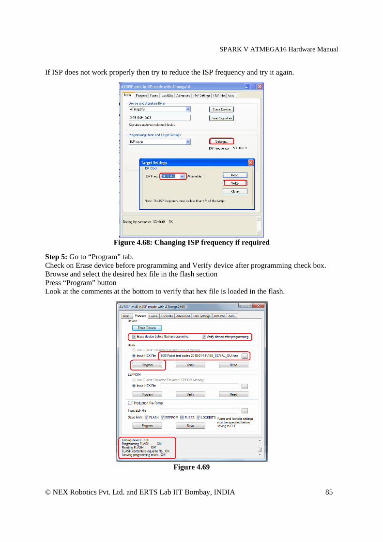
If ISP does not work properly then try to reduce the ISP frequency and try it again.
Figure 4.68: Changing ISP frequency if required
Step 5: Go to “Program” tab. Check on Erase device before programming and Verify device after programming check box. Browse and select the desired hex file in the flash section Press “Program” button Look at the comments at the bottom to verify that hex file is loaded in the flash.
Figure 4.69

SPARK V ATMEGA16 Hardware Manual
© NEX Robotics Pvt. Ltd. and ERTS Lab IIT Bombay, INDIA 86
4.8.1 Fuse settings for ATMEGA16 microcontroller Correct Fuse settings are done in the ATMEGA16 microcontroller before shipping out Spark V robot.. Do not change them unless you have very clear understanding of the fuse settings. This information is only given for the reference.
Figure 4.70
Figure 4.71: Fuse settings of ATMEGA16 microcontroller

SPARK V ATMEGA16 Hardware Manual
© NEX Robotics Pvt. Ltd. and ERTS Lab IIT Bombay, INDIA 87
Go the “Fuse” tab while robot is powered on and AVRISP mkII is connected. Press “Read” button. All the fuse settings will be visible. Brown-out detection is disabled. JTAGEN is set at Brown-out detection at VCC=2.7V Boot size is at 4096 words with start address = $1C00 SUT_CKSEL is set at External crystal greater than 8MHz with startup time of 64ms If needed you can set appropriate Fuse setting and write it by pressing “Program” button.

SPARK V ATMEGA16 Hardware Manual
© NEX Robotics Pvt. Ltd. and ERTS Lab IIT Bombay, INDIA 88
5. Pin Functionality ATMEGA16 microcontroller pin configuration
PINNO Pin name USED FOR Status
1 (XCO/T0)PB0 Logic output 1 for Left motor (Left back) Output 2 (T1)PB1 Logic output 2 for Left motor (Left back) Output 3 (INT2/AIN0)PB2 Logic output 1 for Right motor (Right back) Output 4 (OC0/AIN1)PB3 Logic output 2 for Right motor (Right back) Output 5 (SS)PB4 Output 6 (MOSI)PB5 Output 7 (MISO)PB6 Input 8 (SCK)PB7
ISP (In System Programming)
Output 9 RESET Microcontroller reset Default 10 VCC 5V -- 11 GND Ground -- 12 XTAL1 Default 13 XTAL2
Crystal 7.3728 MHz Default
14 (RXD)PD0 UART Receive* Input 15 (TXD)PD1 UART Transmit* Output
16 (INT0)PD2 Position Encoder input for Left Motor, TSOP1738 output** Input
17 (INT1)PD3 Position Encoder input for Right Motor Input 18 (OC1B)PD4 PWM output for Left Motor Output 19 (OC1A)PD5 PWM output for Right Motor Output
20 (ICP1)PD6 Ultrasonic Trigger Input Left (sensor no. 1) ultrasonic sensor*** Output
21 (OC2)PD7 Boot loader switch / Servo Pod output Input / Output
22 PC0(SCL) LCD control line RS (Register Select) Output 23 PC1(SDA) LCD control line RW(Read/Write Select) Output 24 PC2(TCK) LCD control line EN(Enable Signal) Output 25 PC3(TMS) Buzzer Output 26 PC4(TDO) 27 PC5(TDI) 28 PC6(TOSC1) 29 PC7(TOSC2)
LCD data lines (4-bit mode) Output
30 AVCC 5V --
31 AGND Ground -- 32 AREF ADC reference voltage pin (5V external) **** -- 33 PA7 (ADC7) ADC input for External ultrasonic sensor Input***** 34 PA6(ADC6) ADC input for battery voltage monitoring Input***** 35 PA5(ADC5) ADC input for white line sensor Right Input***** 36 PA4(ADC4) ADC input for white line sensor Center Input***** 37 PA3(ADC3) ADC input for white line sensor Left Input*****
SPARK V ATMEGA16 Hardware Manual
© NEX Robotics Pvt. Ltd. and ERTS Lab IIT Bombay, INDIA 89
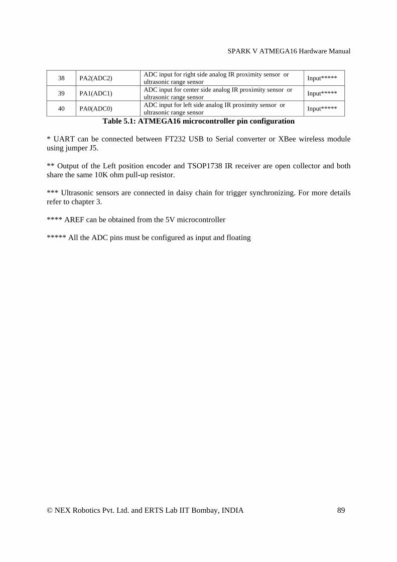
38 PA2(ADC2) ADC input for right side analog IR proximity sensor or ultrasonic range sensor Input*****
39 PA1(ADC1) ADC input for center side analog IR proximity sensor or ultrasonic range sensor Input*****
40 PA0(ADC0) ADC input for left side analog IR proximity sensor or ultrasonic range sensor Input*****
Table 5.1: ATMEGA16 microcontroller pin configuration
* UART can be connected between FT232 USB to Serial converter or XBee wireless module using jumper J5. ** Output of the Left position encoder and TSOP1738 IR receiver are open collector and both share the same 10K ohm pull-up resistor. *** Ultrasonic sensors are connected in daisy chain for trigger synchronizing. For more details refer to chapter 3. **** AREF can be obtained from the 5V microcontroller ***** All the ADC pins must be configured as input and floating

SPARK V ATMEGA16 Hardware Manual
© NEX Robotics Pvt. Ltd. and ERTS Lab IIT Bombay, INDIA 90
6. PC Based Control Using Serial Communication In this chapter, simple robot control over wired (USB) or wireless medium (XBee wireless module) is covered. User can expand this protocol further to write his own applications. Using good packet based protocol; user can design applications involving complex multi robot communication scheme with robots to robots and robots to PCs simultaneous communication. A more bit advanced communication protocol for the robot control and sensor data acquisition is covered in the chapter 7. Spark V ATMEGA16 robot can communicate with the PC using USB or XBee wireless module. 6.1: Communication protocol for simple robot control
Character ASCII value Action 8 0x38 Forward 2 0x32 Backward 4 0x34 Left 6 0x36 Right 5 0x35 Stop 7 0x37 Buzzer On 9 0x39 Buzzer Off
Table 6.1 Table 6.1 shows the simple robot control protocol. Using this, robot can be moved in forward, backward, left or right directions and its buzzer can be turned on or off. You can use any serial port control software such as hyper terminal or terminal.exe etc. For user friendliness keys of the numerical pad of standard 104 keys querty keyboards are used. When a particular number key is pressed, its ASCII character value is transmitted over serial / USB port. Robot receives this ASCII values and based on its value it actuates its motors, buzzer etc. Keys are mapped in the intuitive way on the Numerical pad of the keyboard. This communication protocol is covered in the “10A_Serial_Communication_USB” and “10B_Serial_Communication_ZigBee” projects which are located in the “Experiments” folder in the documentation CD. Section 6.2 and 6.3 covers robot control using PC’s USB port and XBee wireless module. Important: While using “Numerical Pad” of the key board, make sure that “Num. Lock” is on. 6.2 Robot control using USB port
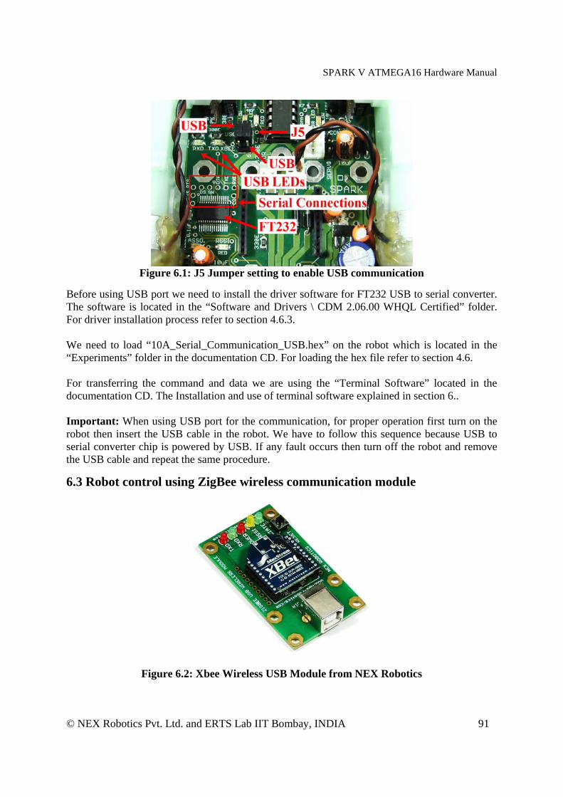
Spark V ATMEGA16 has onboard USB port for direct interface with PC. USB interfacing is based on FT232 USB to serial converter. Serial port of the ATMEGA16 can be connected to either USB port via FT232 USB to serial converter or to XBee wireless module. To connect TXD and the RXD of the microcontroller to FT232 USB to serial converter, Jumper J5 needs to be set in the correct setting. Refer to figure 6.1 for the jumper setting to use USB port.
SPARK V ATMEGA16 Hardware Manual
© NEX Robotics Pvt. Ltd. and ERTS Lab IIT Bombay, INDIA 91
Figure 6.1: J5 Jumper setting to enable USB communication
Before using USB port we need to install the driver software for FT232 USB to serial converter. The software is located in the “Software and Drivers \ CDM 2.06.00 WHQL Certified” folder. For driver installation process refer to section 4.6.3. We need to load “10A_Serial_Communication_USB.hex” on the robot which is located in the “Experiments” folder in the documentation CD. For loading the hex file refer to section 4.6. For transferring the command and data we are using the “Terminal Software” located in the documentation CD. The Installation and use of terminal software explained in section 6.. Important: When using USB port for the communication, for proper operation first turn on the robot then insert the USB cable in the robot. We have to follow this sequence because USB to serial converter chip is powered by USB. If any fault occurs then turn off the robot and remove the USB cable and repeat the same procedure.
6.3 Robot control using ZigBee wireless communication module
Figure 6.2: Xbee Wireless USB Module from NEX Robotics

SPARK V ATMEGA16 Hardware Manual
© NEX Robotics Pvt. Ltd. and ERTS Lab IIT Bombay, INDIA 92
XBee USB Wireless Module from the NEX Robotics enables wireless transmission of serial data through PC’s USB port. It uses Xbee module for wireless communication. The Xbee module can be configured via PC’s USB port easily using X-CTU utility to change frequency, baud rate etc. It is located in the “Software and Drivers” folder in the documentation CD. XBee wireless modules accepts serial data from any device. To interface it with the PC, FT232 USB to serial converter is used. To connect XBee USB Wireless Module to the PC you need to install drivers for FT232 USB to serial converter. To install drivers for FT232 USB to serial converter and to identify or change COM port number, refer to section 4.6.3 and 4.6.4. On the PC side this device is treated as the Communication Device Class (CDC) of USB family and it is assigned a virtual Comport number allowing the user to make use of existing GUI. The destination side (robot) requires another XBee wireless module. Make sure that ZigBee wireless module s installed on the robot. Serial port of the ATMEGA16 can be connected to either USB port via FT232 USB to serial converter or to XBee wireless module. To connect TXD and the RXD of the microcontroller to XBee wireless module, Jumper J5 needs to be set in the correct setting. Refer to figure 6.3 for the jumper setting to use Xbee wireless module.
Figure 6.3: Jumper setting to enable XBee wireless module
We need to load “10B_Serial_Communication_ZigBee.hex” on the robot which is located in the “Experiments” folder in the documentation CD. For transferring the command and data we are using the “Terminal Software” located in the “Software” folder of the documentation CD. The Installation of terminal software and its use is explained in section 6.4. Note: Wait for at least 5 seconds to start the wireless communication after turning on the robot and the USB wireless module.
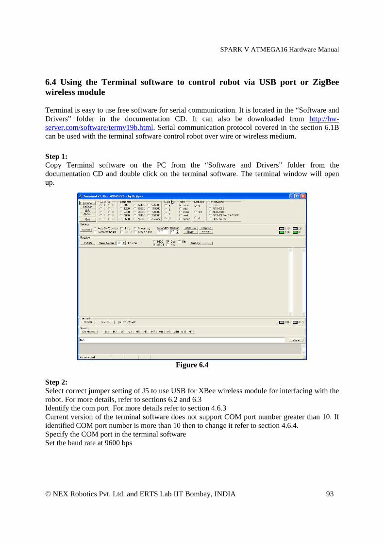
SPARK V ATMEGA16 Hardware Manual
© NEX Robotics Pvt. Ltd. and ERTS Lab IIT Bombay, INDIA 93
6.4 Using the Terminal software to control robot via USB port or ZigBee wireless module Terminal is easy to use free software for serial communication. It is located in the “Software and Drivers” folder in the documentation CD. It can also be downloaded from http://hw-server.com/software/termv19b.html. Serial communication protocol covered in the section 6.1B can be used with the terminal software control robot over wire or wireless medium. Step 1: Copy Terminal software on the PC from the “Software and Drivers” folder from the documentation CD and double click on the terminal software. The terminal window will open up.
Figure 6.4
Step 2: Select correct jumper setting of J5 to use USB for XBee wireless module for interfacing with the robot. For more details, refer to sections 6.2 and 6.3 Identify the com port. For more details refer to section 4.6.3 Current version of the terminal software does not support COM port number greater than 10. If identified COM port number is more than 10 then to change it refer to section 4.6.4. Specify the COM port in the terminal software Set the baud rate at 9600 bps
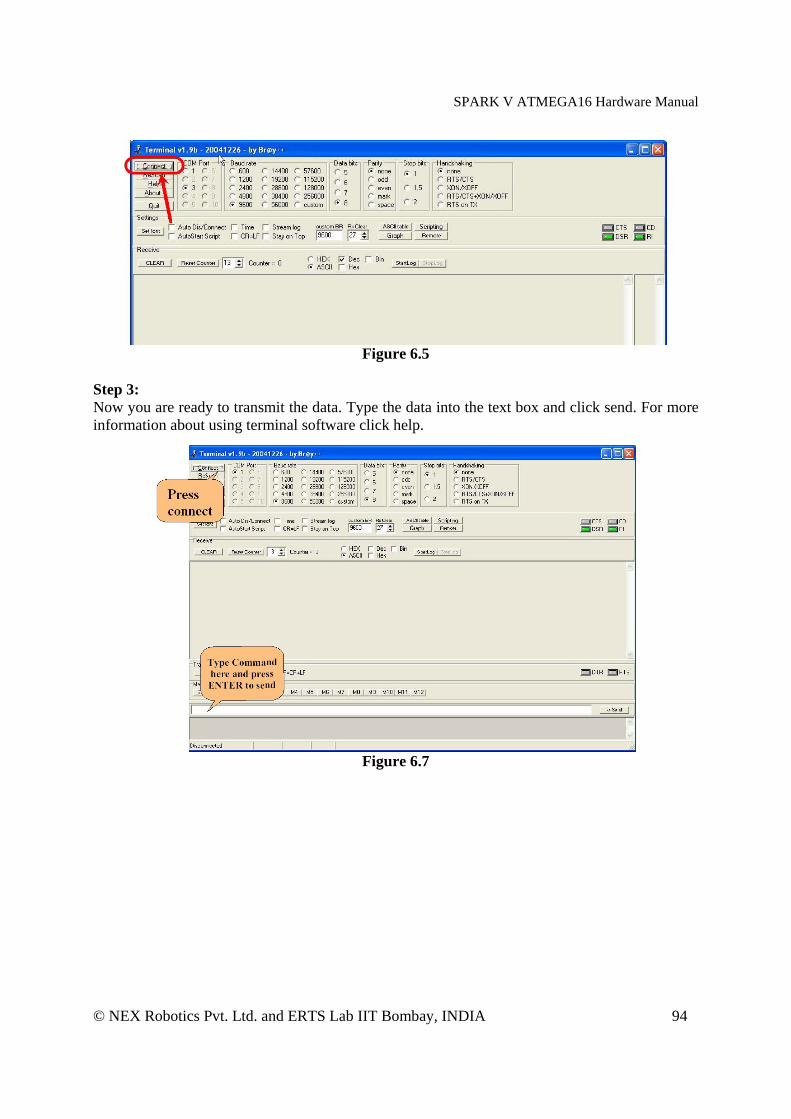
SPARK V ATMEGA16 Hardware Manual
© NEX Robotics Pvt. Ltd. and ERTS Lab IIT Bombay, INDIA 94
Figure 6.5
Step 3: Now you are ready to transmit the data. Type the data into the text box and click send. For more information about using terminal software click help.
Figure 6.7
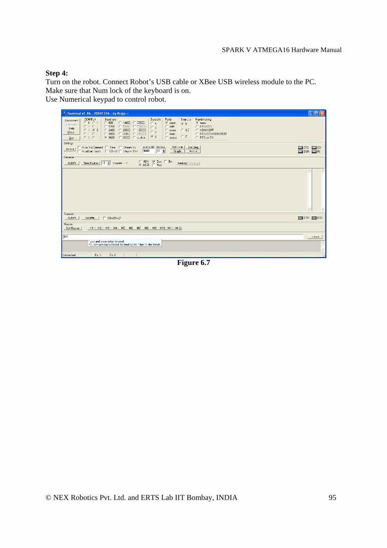
SPARK V ATMEGA16 Hardware Manual
© NEX Robotics Pvt. Ltd. and ERTS Lab IIT Bombay, INDIA 95
Step 4: Turn on the robot. Connect Robot’s USB cable or XBee USB wireless module to the PC. Make sure that Num lock of the keyboard is on. Use Numerical keypad to control robot.
Figure 6.7
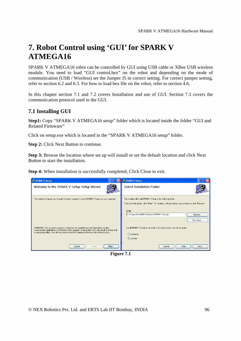
SPARK V ATMEGA16 Hardware Manual
© NEX Robotics Pvt. Ltd. and ERTS Lab IIT Bombay, INDIA 96
7. Robot Control using ‘GUI’ for SPARK V ATMEGA16 SPARK V ATMEGA16 robot can be controlled by GUI using USB cable or XBee USB wireless module. You need to load “GUI control.hex” on the robot and depending on the mode of communication (USB / Wireless) set the Jumper J5 in correct setting. For correct jumper setting, refer to section 6.2 and 6.3. For how to load hex file on the robot, refer to section 4.6. In this chapter section 7.1 and 7.2 covers Installation and use of GUI. Section 7.3 covers the communication protocol used in the GUI. 7.1 Installing GUI Step1: Copy “SPARK V ATMEGA16 setup” folder which is located inside the folder “GUI and Related Firmware” Click on setup.exe which is located in the “SPARK V ATMEGA16 setup” folder. Step 2: Click Next Button to continue. Step 3: Browse the location where set up will install or set the default location and click Next Button to start the installation. Step 4: When installation is successfully completed, Click Close to exit.
Figure 7.1
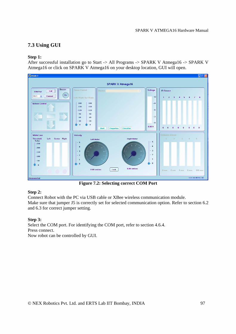
SPARK V ATMEGA16 Hardware Manual
© NEX Robotics Pvt. Ltd. and ERTS Lab IIT Bombay, INDIA 97
7.3 Using GUI Step 1: After successful installation go to Start -> All Programs -> SPARK V Atmega16 -> SPARK V Atmega16 or click on SPARK V Atmega16 on your desktop location, GUI will open.
Figure 7.2: Selecting correct COM Port
Step 2: Connect Robot with the PC via USB cable or XBee wireless communication module. Make sure that jumper J5 is correctly set for selected communication option. Refer to section 6.2 and 6.3 for correct jumper setting. Step 3: Select the COM port. For identifying the COM port, refer to section 4.6.4. Press connect. Now robot can be controlled by GUI.
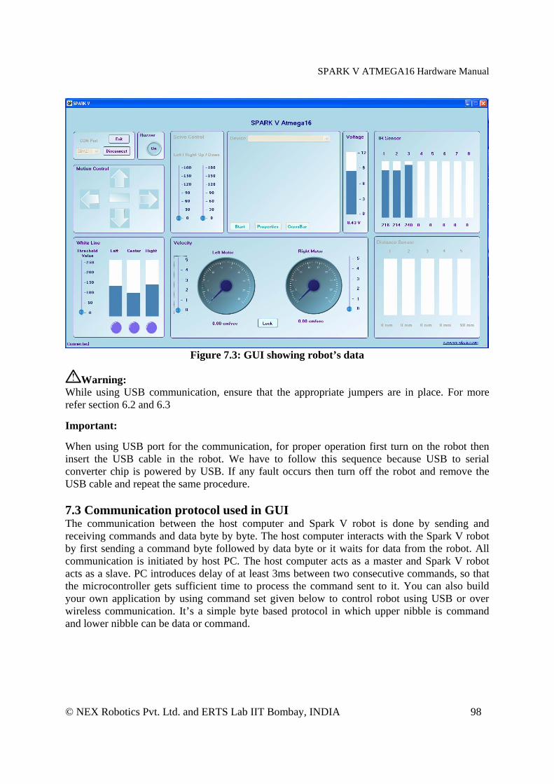
SPARK V ATMEGA16 Hardware Manual
© NEX Robotics Pvt. Ltd. and ERTS Lab IIT Bombay, INDIA 98
Figure 7.3: GUI showing robot’s data
Warning: While using USB communication, ensure that the appropriate jumpers are in place. For more refer section 6.2 and 6.3 Important: When using USB port for the communication, for proper operation first turn on the robot then insert the USB cable in the robot. We have to follow this sequence because USB to serial converter chip is powered by USB. If any fault occurs then turn off the robot and remove the USB cable and repeat the same procedure. 7.3 Communication protocol used in GUI The communication between the host computer and Spark V robot is done by sending and receiving commands and data byte by byte. The host computer interacts with the Spark V robot by first sending a command byte followed by data byte or it waits for data from the robot. All communication is initiated by host PC. The host computer acts as a master and Spark V robot acts as a slave. PC introduces delay of at least 3ms between two consecutive commands, so that the microcontroller gets sufficient time to process the command sent to it. You can also build your own application by using command set given below to control robot using USB or over wireless communication. It’s a simple byte based protocol in which upper nibble is command and lower nibble can be data or command.
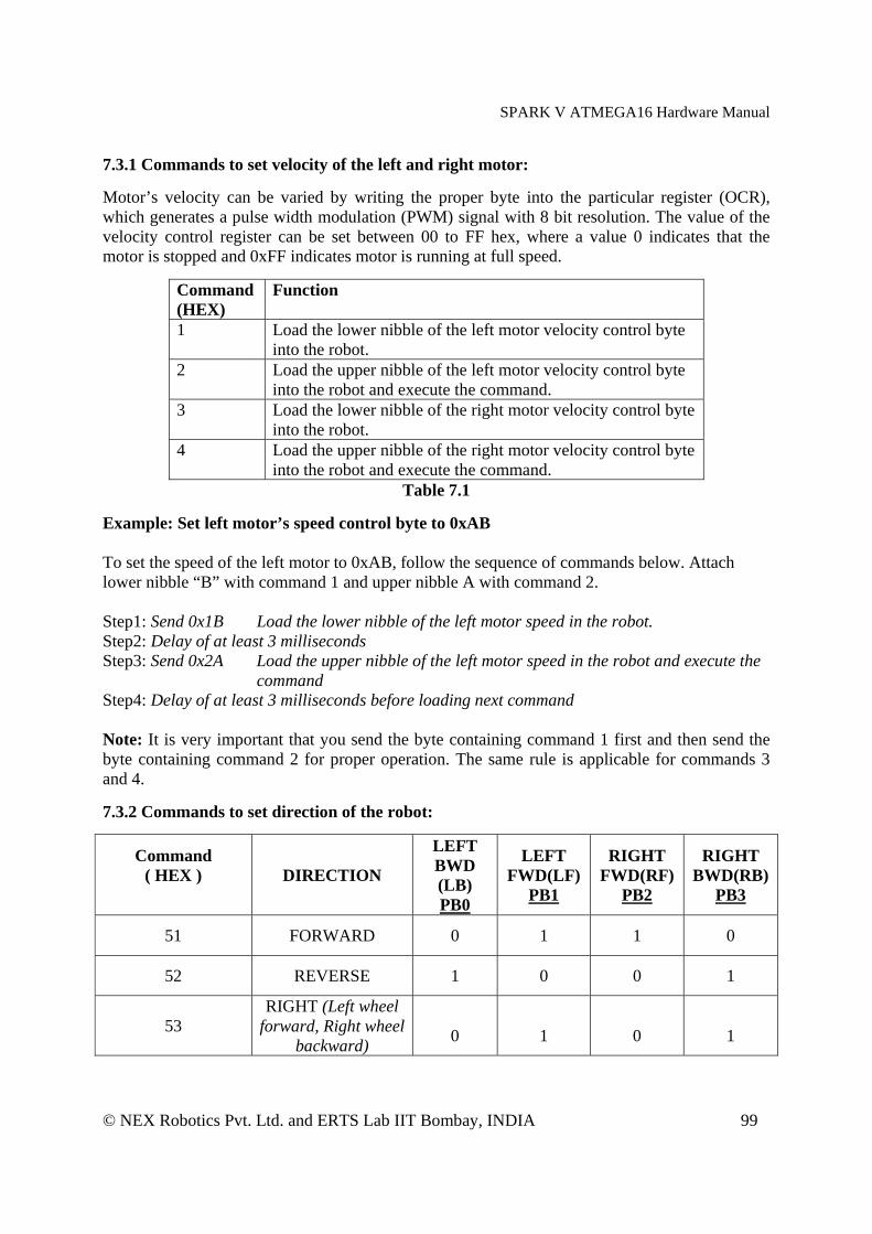
SPARK V ATMEGA16 Hardware Manual
© NEX Robotics Pvt. Ltd. and ERTS Lab IIT Bombay, INDIA 99
7.3.1 Commands to set velocity of the left and right motor: Motor’s velocity can be varied by writing the proper byte into the particular register (OCR), which generates a pulse width modulation (PWM) signal with 8 bit resolution. The value of the velocity control register can be set between 00 to FF hex, where a value 0 indicates that the motor is stopped and 0xFF indicates motor is running at full speed.
Command (HEX)
Function
1 Load the lower nibble of the left motor velocity control byte into the robot.
2 Load the upper nibble of the left motor velocity control byte into the robot and execute the command.
3 Load the lower nibble of the right motor velocity control byte into the robot.
4 Load the upper nibble of the right motor velocity control byte into the robot and execute the command.
Table 7.1
Example: Set left motor’s speed control byte to 0xAB To set the speed of the left motor to 0xAB, follow the sequence of commands below. Attach lower nibble “B” with command 1 and upper nibble A with command 2. Step1: Send 0x1B Load the lower nibble of the left motor speed in the robot. Step2: Delay of at least 3 milliseconds Step3: Send 0x2A Load the upper nibble of the left motor speed in the robot and execute the
command Step4: Delay of at least 3 milliseconds before loading next command Note: It is very important that you send the byte containing command 1 first and then send the byte containing command 2 for proper operation. The same rule is applicable for commands 3 and 4.
7.3.2 Commands to set direction of the robot:
Command ( HEX )
DIRECTION
LEFT BWD (LB) PB0
LEFT FWD(LF)
PB1
RIGHT FWD(RF)
PB2
RIGHT BWD(RB)
PB3
51 FORWARD 0 1 1 0
52 REVERSE 1 0 0 1
53 RIGHT (Left wheel
forward, Right wheel backward)
0
1
0
1

SPARK V ATMEGA16 Hardware Manual
© NEX Robotics Pvt. Ltd. and ERTS Lab IIT Bombay, INDIA 100
54 LEFT(Left wheel backward, Right wheel forward,)
1
0
1
0
59 HARD STOP 0 0 0 0
Table 7.2 Example: To set left motor velocity to 0x84, right motor velocity to 0x65, and move backward. Step1: 0x14 Load the lower nibble ‘4’ of the left motor speed into the robot Step2: Delay of at least 3 milliseconds Step3: 0x28 Load the upper nibble ‘8’ of the left motor speed into the robot and execute the
command Step4: Delay of at least 3 milliseconds Step5: 0x35 Load the lower nibble ‘5’ of the right motor speed into the robot Step6: Delay of at least 3 milliseconds Step7: 0x46 Load the upper nibble ‘6’ of the right motor speed into the robot and execute the
command Step8: Delay of at least 3 milliseconds Step9: 0x52 move backward Step10: Delay of at least 3 milliseconds before loading next command 7.3.3 Commands to access the Analog sensor data:
Command (HEX)
Data
60 Battery voltage Robot sends back 8 bit battery voltage value. To convert this value in to volts use the following conversion formula: Battery Voltage = ADC data x 0.069
64 White line sensor 1 (Left) The Robot will return an 8 bit analog value of the left white line sensor
65 White line sensor 2 (Centre) The Robot will return an 8 bit analog value of the center white line sensor
66 White line sensor 3 (Right) The Robot will return an 8 bit analog value of the right white line sensor
C1 IR Proximity sensor (Left) The Robot will return an 8 bit analog value of the IR Proximity sensor 1
C2 IR Proximity sensor 2 (Centre) The Robot will return an 8 bit analog value of the IR Proximity sensor 2
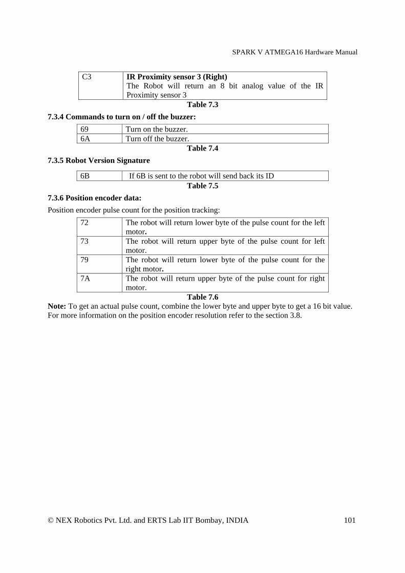
SPARK V ATMEGA16 Hardware Manual
© NEX Robotics Pvt. Ltd. and ERTS Lab IIT Bombay, INDIA 101
C3 IR Proximity sensor 3 (Right) The Robot will return an 8 bit analog value of the IR Proximity sensor 3
Table 7.3
7.3.4 Commands to turn on / off the buzzer:
69 Turn on the buzzer. 6A Turn off the buzzer.
Table 7.4
7.3.5 Robot Version Signature
6B If 6B is sent to the robot will send back its ID Table 7.5
7.3.6 Position encoder data:
Position encoder pulse count for the position tracking:
72 The robot will return lower byte of the pulse count for the left motor.
73 The robot will return upper byte of the pulse count for left motor.
79 The robot will return lower byte of the pulse count for the right motor.
7A The robot will return upper byte of the pulse count for right motor.
Table 7.6 Note: To get an actual pulse count, combine the lower byte and upper byte to get a 16 bit value. For more information on the position encoder resolution refer to the section 3.8.