spark internet of things teaching kit
TRANSCRIPT

Internet of Things Teaching Kit
About the author: MakerKids About this Teaching Kit
Teach By Asking Questions Resources Preparation
Materials Needed Set Up Spark Core
Set up Individual Spark Cores Set up a batch of Spark Cores for a Group
Set Core WiFi Network Electronic Wiring
Materials Needed Prototyping with a Breadboard DoorBell Wiring
Arduino Coding Basics To the Docs! To Google! To the Community Forums! Spark IDE Tour Ring Doorbell
Setup and Loop pinMode() digitalWrite() delay() Ring the DoorBell when the button is pressed If Statements
Variables Repeat Loops
Internet Control Listening for Events from the Internet - Spark Functions Send Messages from the Web to Your Spark - Spark Control Panel
Send messages back to the web from the Spark Build your Own Custom Web Interface More Internet Control
IFTTT Setting up Spark with IFTTT Tutorial activity 1: Spark as an Action for a Trigger Recipes to trigger an action on the Spark Tutorial activity 2: Spark as a Trigger for an Action Recipes to use Spark as a trigger for internet events
1 / 60

Sample Projects Parts Wiring The Electronics Spark Code
Motion sensing thing Parts Wiring Spark Code
Security Privacy
About the author: MakerKids MakerKids (www.makerkids.com) develops maker learning programs for kids and educators, and runs one of the only makerspaces for kids in the world. Our Board of Advisors includes Dale Dougherty (CEO of Maker Media, MAKE Magazine and Maker Faire) and Massimo Banzi (CEO of Arduino). We enable kids to build their ideas with real tools and materials; our goal is to inspire and empower kids to think, design, experiment and create. Our three main offerings are currently: 1) Programs: Camps, after-school programs, birthday parties and activities at external events where kids can learn about and do things like 3D printing, electronics and woodworking, 2) Content and Curriculum Development for clients like Intel and 3D Systems, and 3) Professional Development services for clients such as the Toronto Public Library. We've been featured in major media such as Wired, CTV and the Globe and Mail, and have spoken at SXSW, Maker Faire, MakerCon, and more.
2 / 60

MakerKids is one of the only kids' makerspaces in the world, with a workshop in
Toronto, globally recognized as a leader in teaching high-tech making to kids. Our goal is to inspire and empower kids aged 3+ to think, design, build ideas, experiment and create. Our programs encourage self-directed learning and discovery, and collaborative learning. Improved engagement, behaviour, confidence, and social skills have been reported through participation in our programs. We run programs on-site, such as after-school, camps, workshops, etc.
MakerKids is continually proven to be a leader for providing hands-on maker activities for external events. MakerKids has been hired to provided similar activities at OLA Super Conference, Maker Faire Rome, Maker Faire Bay Area, Mini Maker Faire Toronto, the ROM, Harbourfront Centre, Fort York, the Textile Museum, school events, among others. MakerKids has delivered presentations at Maker Faire Rome, the Creative Making in Libraries and Museums Symposium, Maker Faire Bay Area, and Maker Faire Toronto. 3000+ kids have participated in programs at MakerKids. Many come from all over the GTA and beyond, and many have mental health diagnoses or autism. 10,000+ kids have participated in external programs. We have been featured in the Globe and Mail, Toronto Life magazine, Breakfast Television. CTV, WIRED magazine, Make: magazine, the Huffington Post, CBC television and TVO.
We have been hired to create curriculum modules for companies like Intel and 3D systems. Here are some modules for educators that we created as part of a grant we received: Arduino and Toy Hacking. MakerKids also has experience developing programs specifically to meet school board curriculum requirements, as we received a Mozilla HIVE foundation grant for our MakerSchools project – developing maker activities to be taught in classes.
We have been hired to conduct educator training sessions by the Toronto Public Library, and by the Computers in Libraries conference, and the OLA Superconference where we led full day educator training sessions. We have trained over 1000 librarians and educators on how to teach 3D printing, Arduino, computer programming, and how to implement maker activities in schools and libraries. This Internet of Things teaching kit was written by Andy Forest, Erica Tiberia and Daniel Rother.
Canadian Internet Registration Authority (CIRA) Community Investment Program
3 / 60

This teaching kit is made possible through funding by the Canadian Internet Registration Authority (CIRA) Community Investment Program. We’re very grateful and happy that CIRA is funding projects to help connect all Canadians, and build an Internet for the future.
For more information on CIRA or the Community Investment Program, visit the CIRA web site.
About this Teaching Kit The goal of this teaching kit is to enable anyone to create Internet of Things Robots! Digital literacy is an important topic that everyone should learn. Our world is increasingly build out of devices that are programmed. If you don’t know how to create them, you are stuck only being able to consume other people’s ideas. Many teachers feel that they need an extensive programming background to teach programming to kids. There is very little freely available, compelling kids programming curriculum that shows them how to teach this topic. That is why a main target audience of this teaching kit is non-expert teachers. Anyone should will be able to use this teaching kit along with inexpensive hardware to teach kids to make amazing Internet of Things projects! Even if you already know how to code, teaching programming to others can be daunting. When teaching robotics to kids, we find that one of the biggest challenges is to keep their interest long enough to do something awesome. The electronics, code, and mechanisms necessary to accomplish their ideas can be complex, with a lot needing to be completed before they can see anything working. So another important target audience for this teaching kit is non-teachers. The structure of the kit will enable anyone to teach this topic to others or themselves! This kit will allow people to get up to speed on the electronics and mechanisms quickly by working on easy to follow examples. These start very simple, and incorporate many different kinds of sensors and outputs to give students a broad understanding of what is possible. To teach people the coding skills they need, this kit takes two approaches. The first is that we have developed code libraries to allow very easy ways to access complex communication between the robot, web browsers and other actions on the Internet. These libraries will allow the user to:
4 / 60
Control the Robot from a web browser Report sensor data to a web browser Trigger actions on the Internet from the robot Trigger actions on the robot from the Internet
The next part of the approach is to teach the basics of coding through examples using these libraries. This kit incorporates teaching:
Commands Variables Control structures Function calls
By learning these basics in this way, the participants don’t even notice that we’re building a foundation of skills! They just know that they are creating awesome Internet controlled robots! After they have these building blocks mastered, they can unleash their creativity and create anything they can imagine! The code examples are always there for them to refer to and copy from when they are developing their own projects. The final gap that this project will fill is privacy. Internet connected devices have a high potential for privacy abuses. By providing an open source Internet of Things platform for everyone, we are helping address this issue. All the code can be inspected by the community to ensure that it does not contain privacy problems. The teaching kits will also talk about privacy issues around connecting sensors to the Internet, and encourage the kids to think about these issues.
Teach By Asking Questions A highly effective method of teaching technology skills is by asking questions and helping guide your learners towards discovering the answers. If they discover it for themselves, and use it right away, they are much more likely to remember it! The teaching guide is structured to allow you to teach in this way. Each concept to be introduced will have this structure:
1. Introduction: What is the concept? 2. Question: Ask the learners - why is this concept important?
Guide them towards the answer, expand the importance of the concept 3. Explain: Details of the concept and how it is used.
5 / 60
4. Challenge: Give the learners a challenge and ask them to implement the concept to solve it
5. Going Further: Implement the concept in your own way Everyone proceeds at their own pace. Give faster learners extra challenges as often as possible to keep them engaged, and let them keep learning!
Resources It is important to utilize online resources whenever necessary to learn on your own. Encourage your learners to do the same. Here are the key online reference materials for this topic: Arduino Reference library: http://arduino.cc/en/Reference Spark Documentation: http://docs.spark.io/firmware/ Control Panel link: https://andyforest.github.io/sparkControl/examples/Spark_Control_Panel.html Spark Library documentation: https://github.com/AndyForest/sparkControl
Preparation
Materials Needed Each participant or group will need:
Spark Core or Photon board. Order online from https://www.spark.io/ USB cable Solderless breadbord Computer LED Button
The group will also need the materials for the sample projects. See the Sample Projects section below for details on their components.
6 / 60

Set Up Spark Core Spark devices are programmed through the spark.io web site. To use this website, you will need a free account. Part of the process below will have you and your learners set up an account.
Set up Individual Spark Cores The easiest way to set up a single spark core is to use their smartphone app. If you do not have a smartphone, you can use the batch process detailed below.
iPhone Android
The app will walk you through the process of setting up an account, connecting your new core to the Internet and the Spark cloud, and claiming it to your account. If you have any difficulties, the Spark web site has additional information: http://docs.spark.io/start/
Set up a batch of Spark Cores for a Group If you are setting up a bunch of Cores, it can be easier to skip the smartphone app and preconfigure your Cores with your wifi network connection information. This will also prevent your participants from accidentally claiming the wrong Spark.
Set Core WiFi Network This step must be done for each Core you wish to configure. First, download the Spark Windows drivers, and extract the zip file. Mac and Linux installation instructions are on the Spark website. Next, plug your Spark Core into your computer. It should be flashing blue (not light blue, cyan or any other colour). If it is not, press and hold the “Mode” button for 3-5 seconds until it starts flashing blue. Open Device Manager on your computer by pressing the start menu button and typing Device Manager:
7 / 60

8 / 60
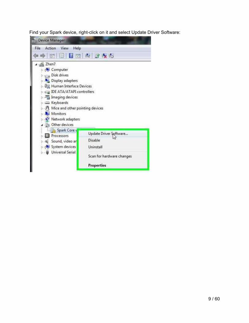
Find your Spark device, right-click on it and select Update Driver Software:
9 / 60
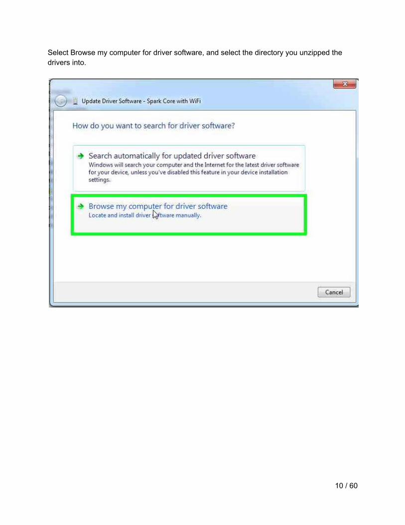
Select Browse my computer for driver software, and select the directory you unzipped the drivers into.
10 / 60
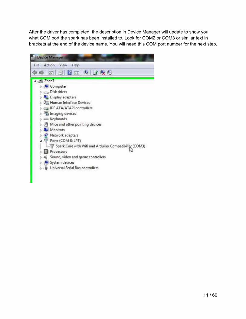
After the driver has completed, the description in Device Manager will update to show you what COM port the spark has been installed to. Look for COM2 or COM3 or similar text in brackets at the end of the device name. You will need this COM port number for the next step.
11 / 60

Next, download the serial terminal program PuTTY. Launch the program and select Connection Type: Serial
12 / 60

Change the COM port to match the one you looked up for your Spark:
Click the Open button to connect to the Spark.
13 / 60

A black terminal window will open. Press the letter i on your keyboard to get the unique ID for this Spark Core chip. Write this number down, and include it on a piece of paper or tape with the Spark in its box. The participant will need this number later to claim the Core to their account.
14 / 60
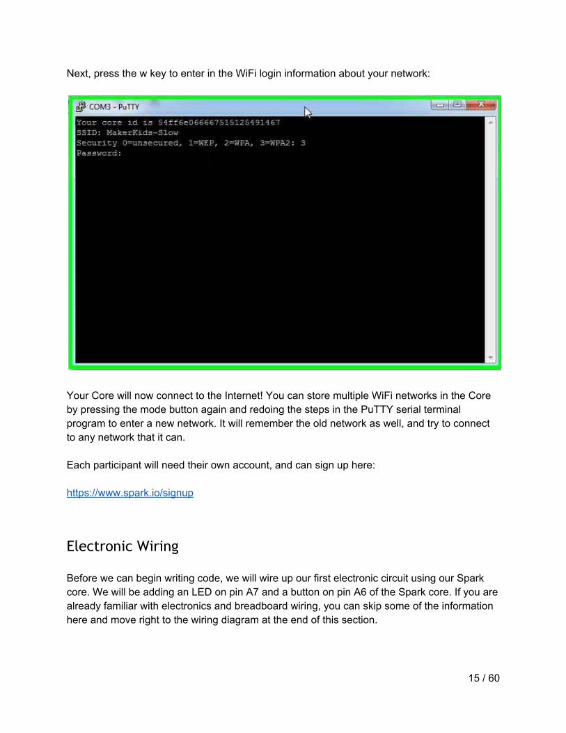
Next, press the w key to enter in the WiFi login information about your network:
Your Core will now connect to the Internet! You can store multiple WiFi networks in the Core by pressing the mode button again and redoing the steps in the PuTTY serial terminal program to enter a new network. It will remember the old network as well, and try to connect to any network that it can. Each participant will need their own account, and can sign up here: https://www.spark.io/signup
Electronic Wiring Before we can begin writing code, we will wire up our first electronic circuit using our Spark core. We will be adding an LED on pin A7 and a button on pin A6 of the Spark core. If you are already familiar with electronics and breadboard wiring, you can skip some of the information here and move right to the wiring diagram at the end of this section.
15 / 60

Materials Needed Solderless breadboard Spark core Wires Button LED
Prototyping with a Breadboard We need an easy way to create electronic circuits! When you’re making a prototype, you need to quickly create, test and make changes. Question: Who’s seen inside an electronic device? Does it look easy to put together? Why not? Explain: Solderless electronics breadboards are great for making temporary circuits and prototyping ideas, and require no soldering. At first glance, all of the holes on a breadboard may look the exact same, but if we take it apart and see what’s inside, we will understand much more about how a breadboard works. Here is a breadboard with the backing removed. You can see the horizontal rows of metal strips connecting the holes together. The outside vertical columns are also connected with metal strips.
16 / 60
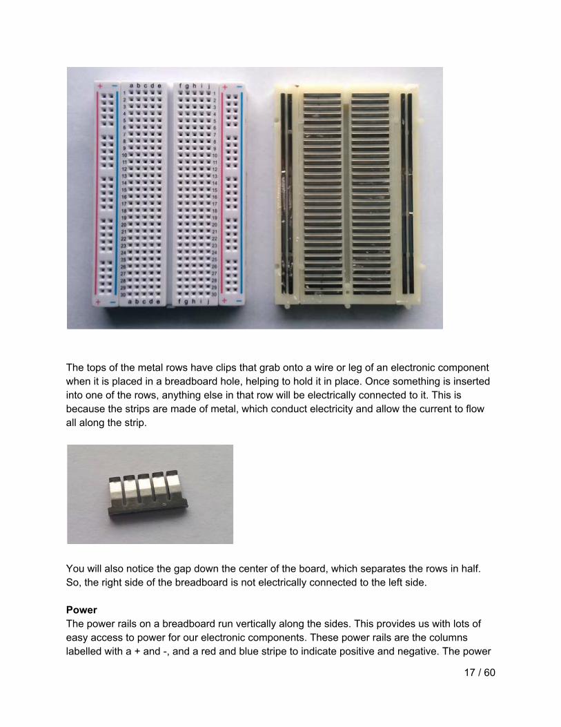
The tops of the metal rows have clips that grab onto a wire or leg of an electronic component when it is placed in a breadboard hole, helping to hold it in place. Once something is inserted into one of the rows, anything else in that row will be electrically connected to it. This is because the strips are made of metal, which conduct electricity and allow the current to flow all along the strip.
You will also notice the gap down the center of the board, which separates the rows in half. So, the right side of the breadboard is not electrically connected to the left side. Power The power rails on a breadboard run vertically along the sides. This provides us with lots of easy access to power for our electronic components. These power rails are the columns labelled with a + and -, and a red and blue stripe to indicate positive and negative. The power
17 / 60
rails on each side of the board are not connected to each other, but you could connect them with a wire reaching across the breadboard if you need to. To provide power to the breadboard, we will connect the pins of the Spark, which gets its power from the USB port on a computer or an external power supply, to the power rails of the breadboard. Challenge: Light up an LED! An LED has 2 pins, and these need to be connected to power and ground. Plug your Spark Core board into the breadboard so that we can have as many holes as possible connected to each pin on the Spark Core board. As shown in the wiring diagram below, use a wire to connect the GND (ground, or negative) pin of the Spark to one of the negative power rails of the breadboard by inserting one end of the wire into the same row of the breadboard as the GND pin, and the other end into the negative power rail column. Do the same to connect the 3.3V (3.3 volts, or positive) to the positive power rails of the breadboard.
DoorBell Wiring It’s time to build our first electric circuit! This circuit will be used in your first coding exercise below, an electronic DoorBell. LED A LED (Light Emitting Diode) has two metal legs, or leads, which we can connect to our circuit. Because this bulb is a Diode, it allows the electric current to pass in only one direction. One of the leads is the anode (negative), and the other is the cathode (positive). You can tell which leg is which because the positive lead is slightly longer than the negative. If you have a button cell battery, you can test how a LED works by holding the legs up to either side of a battery. You can touch the longer positive leg up to the positive side of the battery, and the shorter leg to the negative side of the battery, and your LED will turn on. If you try swapping the legs, you will notice that the light no longer turns on. The current can only pass in one direction, and when it is able to pass through the bulb, some of the electricity is emitted as light. Plug the short leg of the LED into the negative power rail of your breadboard, and the long leg into the row of the breadboard that is also connected to A7 of your Spark core. Button A button or switch makes or breaks a connection between the input pin on the Spark core and GND. The input pin will be able to tell us whether the button has been pressed.
18 / 60
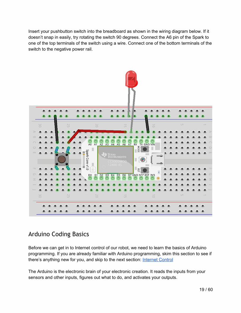
Insert your pushbutton switch into the breadboard as shown in the wiring diagram below. If it doesn’t snap in easily, try rotating the switch 90 degrees. Connect the A6 pin of the Spark to one of the top terminals of the switch using a wire. Connect one of the bottom terminals of the switch to the negative power rail.
Arduino Coding Basics Before we can get in to Internet control of our robot, we need to learn the basics of Arduino programming. If you are already familiar with Arduino programming, skim this section to see if there’s anything new for you, and skip to the next section: Internet Control The Arduino is the electronic brain of your electronic creation. It reads the inputs from your sensors and other inputs, figures out what to do, and activates your outputs.
19 / 60
In order for it to know what to do, you must program it with instructions. These instructions tell it how to react to the inputs, and control the outputs. Once the Arduino is programmed, it is stand-alone, its programming is self-contained and it can function on its own. Our Spark Core Chip has 16 “Input/Output” pins, labelled A0 through A7 and D0 through D7. Each one of these can be connected to an input for receiving information from a sensor, or connected to an output to make something happen.
To the Docs! This teaching kit will take you step by step through a number of exercises designed to introduce you to all the Arduino programming basics that you will need to make your own exciting projects. When you are working on your own projects, you need to know where to turn if you are having trouble. If you are a teacher, frequently ask your students questions that you know they do not know the answer to. Get them used to answering your questions with an answer about how they can find out! The first place to look is at the documentation. Whenever there is a question about a command that they don’t know how to access, get them to chant “To the docs!”. Then get them to explore this link: http://docs.spark.io/firmware/ One of the most useful sections of the documentation is the list of commands. Scroll the left-hand menu bar down to see the list of commands, sorted into categories. For example, in the Ring Doorbell exercises below, get them to find the INPUT/OUTPUT sections and explore the commands to try and figure out the answers for themselves:
20 / 60

To Google! Another great resource is the online community of Arduino programmers. For any given project, somebody has probably already written some code that you could learn from. When you or your students are ready to tackle their own Arduino projects, get them to start by Googling for similar projects. Learn about the code they wrote, the components they used. Most Arduino code will work just fine as-is on the Spark devices used in this teaching kit.
To the Community Forums! Spark also has a community forum dedicated to sharing and helping each other with projects. https://community.spark.io/ Browse the forums for solutions, post questions, and help out other people with answers!
Spark IDE Tour Programming any Arduino device is done through an integrated development environment (IDE). This is a special text editor that lets you send your program to the Arduino for processing.
21 / 60

The Spark IDE is web-based, and you will do all of your editing online in a web browser. The Spark Core chip simply needs to be connected to a wifi network, and you can program it remotely from anywhere. Launch the Spark IDE by going to this URL: https://www.spark.io/build
Ring Doorbell It’s time to write your first program! We’ll start off with programming a simple doorbell, and add more and more complex functionality to it until you are an expert coder. Make sure your circuit is set up, as described in the DoorBell Wiring section above.
Setup and Loop
22 / 60
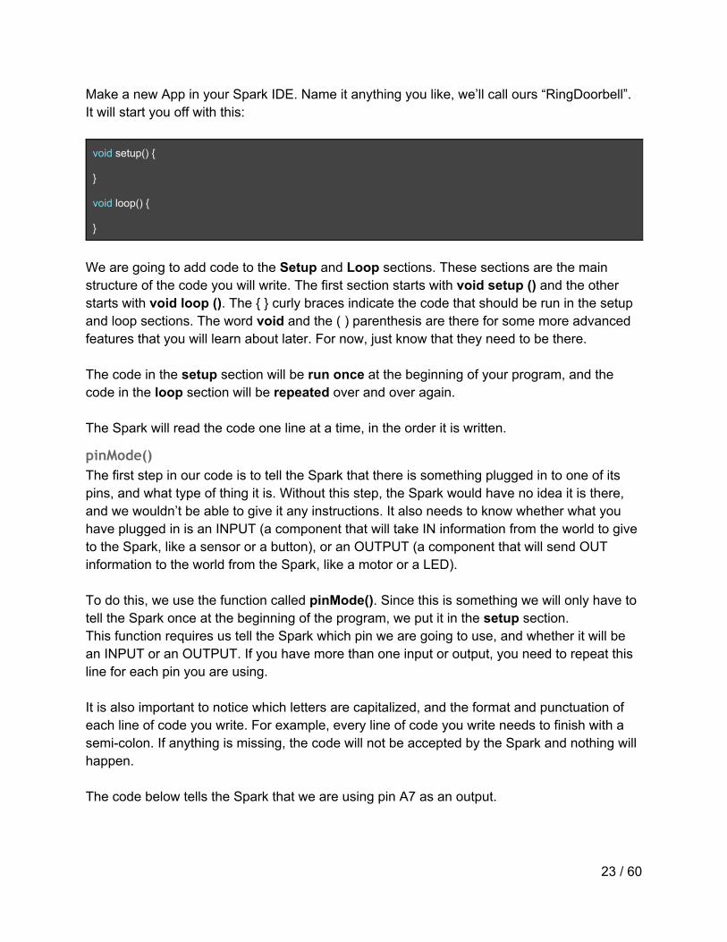
Make a new App in your Spark IDE. Name it anything you like, we’ll call ours “RingDoorbell”. It will start you off with this: void setup() void loop() We are going to add code to the Setup and Loop sections. These sections are the main structure of the code you will write. The first section starts with void setup () and the other starts with void loop (). The curly braces indicate the code that should be run in the setup and loop sections. The word void and the ( ) parenthesis are there for some more advanced features that you will learn about later. For now, just know that they need to be there. The code in the setup section will be run once at the beginning of your program, and the code in the loop section will be repeated over and over again. The Spark will read the code one line at a time, in the order it is written.
pinMode() The first step in our code is to tell the Spark that there is something plugged in to one of its pins, and what type of thing it is. Without this step, the Spark would have no idea it is there, and we wouldn’t be able to give it any instructions. It also needs to know whether what you have plugged in is an INPUT (a component that will take IN information from the world to give to the Spark, like a sensor or a button), or an OUTPUT (a component that will send OUT information to the world from the Spark, like a motor or a LED). To do this, we use the function called pinMode(). Since this is something we will only have to tell the Spark once at the beginning of the program, we put it in the setup section. This function requires us tell the Spark which pin we are going to use, and whether it will be an INPUT or an OUTPUT. If you have more than one input or output, you need to repeat this line for each pin you are using. It is also important to notice which letters are capitalized, and the format and punctuation of each line of code you write. For example, every line of code you write needs to finish with a semi-colon. If anything is missing, the code will not be accepted by the Spark and nothing will happen. The code below tells the Spark that we are using pin A7 as an output.
23 / 60
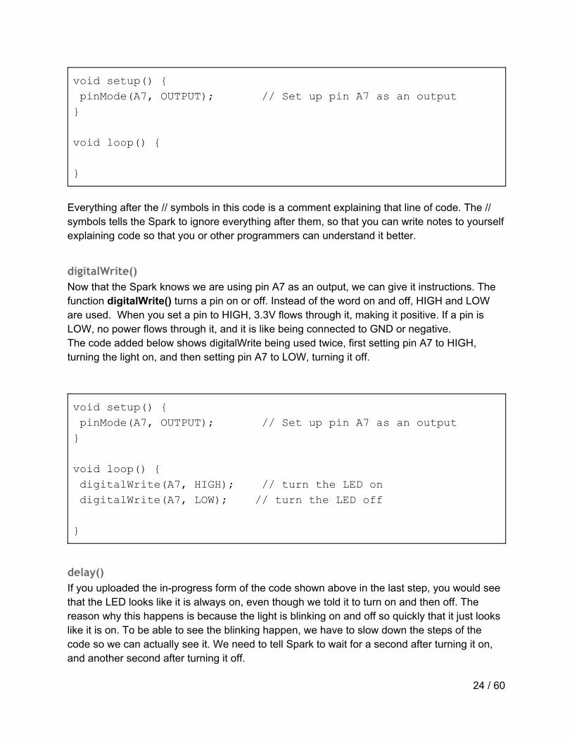
void setup() pinMode(A7, OUTPUT); // Set up pin A7 as an output void loop() Everything after the // symbols in this code is a comment explaining that line of code. The // symbols tells the Spark to ignore everything after them, so that you can write notes to yourself explaining code so that you or other programmers can understand it better.
digitalWrite() Now that the Spark knows we are using pin A7 as an output, we can give it instructions. The function digitalWrite() turns a pin on or off. Instead of the word on and off, HIGH and LOW are used. When you set a pin to HIGH, 3.3V flows through it, making it positive. If a pin is LOW, no power flows through it, and it is like being connected to GND or negative. The code added below shows digitalWrite being used twice, first setting pin A7 to HIGH, turning the light on, and then setting pin A7 to LOW, turning it off. void setup() pinMode(A7, OUTPUT); // Set up pin A7 as an output void loop() digitalWrite(A7, HIGH); // turn the LED on digitalWrite(A7, LOW); // turn the LED off
delay() If you uploaded the in-progress form of the code shown above in the last step, you would see that the LED looks like it is always on, even though we told it to turn on and then off. The reason why this happens is because the light is blinking on and off so quickly that it just looks like it is on. To be able to see the blinking happen, we have to slow down the steps of the code so we can actually see it. We need to tell Spark to wait for a second after turning it on, and another second after turning it off.
24 / 60
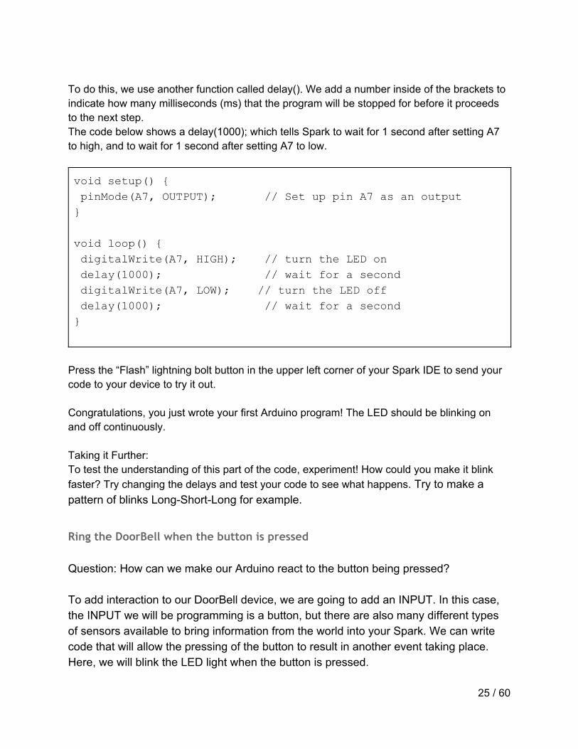
To do this, we use another function called delay(). We add a number inside of the brackets to indicate how many milliseconds (ms) that the program will be stopped for before it proceeds to the next step. The code below shows a delay(1000); which tells Spark to wait for 1 second after setting A7 to high, and to wait for 1 second after setting A7 to low.
void setup() pinMode(A7, OUTPUT); // Set up pin A7 as an output void loop() digitalWrite(A7, HIGH); // turn the LED on delay(1000); // wait for a second digitalWrite(A7, LOW); // turn the LED off delay(1000); // wait for a second
Press the “Flash” lightning bolt button in the upper left corner of your Spark IDE to send your code to your device to try it out. Congratulations, you just wrote your first Arduino program! The LED should be blinking on and off continuously. Taking it Further: To test the understanding of this part of the code, experiment! How could you make it blink faster? Try changing the delays and test your code to see what happens. Try to make a pattern of blinks Long-Short-Long for example.
Ring the DoorBell when the button is pressed Question: How can we make our Arduino react to the button being pressed? To add interaction to our DoorBell device, we are going to add an INPUT. In this case, the INPUT we will be programming is a button, but there are also many different types of sensors available to bring information from the world into your Spark. We can write code that will allow the pressing of the button to result in another event taking place. Here, we will blink the LED light when the button is pressed.
25 / 60

Similar to the first step in our code when we programmed the LED, we must tell the Spark that there is a button plugged in, which pin it is attached to, and that it is an INPUT. When a pin is defined as an INPUT, the Arduino can sense if there is voltage (HIGH) or ground (LOW) attached to that pin. If the pin is disconnected, it will not read a reliable value - it will randomly fluctuate between HIGH and LOW. When we press the button in our circuit, you can see that it will connect pin A6 to GND, which the Arduino will easily be able to read as a LOW. However, when we release the button, the pin is essentially disconnected, and the Arduino will not be able to read a value from it reliably. This is a common problem that the Arduino engineers have solved with a special kind of pinMode setting, INPUT_PULLUP. By specifying this, the Arduino internally compensates, and when there is no connection, it automatically connects that pin to HIGH. This makes it easy for the Arduino to read the state of our button. For this, we use the function pinMode() again in the setup section, but this time we are using pin A6 as an INPUT. In our code, we are going to call A6 an INPUT_PULLUP. Now, when we read the state of pin A6, it will be HIGH when the switch is not pressed and LOW when it is pressed.
void setup() pinMode(A7, OUTPUT); // Set up pin A7 as an output pinMode(A6, INPUT_PULLUP); //Set up pin A6 as an input void loop() digitalWrite(A7, HIGH); // turn the LED on delay(1000); // wait for a second digitalWrite(A7, LOW); // turn the LED off delay(1000); // wait for a second
digitalRead() Now that the Spark knows we are using pin A6 as an INPUT_PULLUP, we can read the value of the pin to see if it is HIGH or LOW. The function digitalRead() has two possible states, HIGH or LOW. When the pin reads the state of the input, it will either be
26 / 60

connected to 5 volts (HIGH) or to ground (LOW). Our button will allow us to change the state being read by the pin by pressing the button. Since one of the legs of the button is connected to pin A6 on the Spark, and the other leg of the button is attached to ground, when we push down on the button, pin A6 is now connected to ground. This allows the pin to read the state of the input as LOW.
If Statements An important programming concept we will use here is an if statement. We want to tell the Spark to only turn on the light IF the button is pressed. If statements can be used to test for a condition, and if the condition is met or true, then something will be done. An if statement will look like this if (condition)
do whatever code is in these curly braces Our condition to test for in this example is IF the button is pressed, or more specifically, we will use digitalRead() to check if A6 == LOW. There are many other comparison operators, such as greater than >, less than <, etc. View the Arduino language reference for a complete list. So let’s add in an if statement to check our button, and only make the LED flash when it’s pressed. Here’s the finished code for this step: void setup() pinMode(A7, OUTPUT); // Set up pin A7 as an output pinMode(A6, INPUT_PULLUP); //Set up pin A6 as an input void loop() if (digitalRead(A6) == LOW) // The button is connected to GND, which is LOW. Pressing the button changes the input on this pin to LOW digitalWrite(A7, HIGH); // turn the LED on delay(1000); // wait for a second digitalWrite(A7, LOW); // turn the LED off delay(1000); // wait for a second Taking it Further:
27 / 60

Add a second button, and have your doorbell ring in a different way when that second button is pressed.
Variables The next key programming concept we’re going to learn is about variables. Question: What do we do if we want to change the pin the LED is attached to from A7 to A5? We go through our code line by line and change all the instances of A7 to A5. This could lead to errors if we missed one. Our code is not very flexible, it’s difficult to change. Variables solve this problem. A variable allows us to define a special label that we can put a data value into, and then use the variable instead of the value. First we must define the variable and the kind of data that we want to store in it. We usually define variables at the top of our code, outside of the setup() and loop() sections. This makes them available for use in any section. int doorBellPin = A7; The “int” word tells the Arduino that we are going to store numbers (Integers) in this variable. “doorBellPin” is the label that we make up for this variable. It can be any word that we want, as long as it doesn’t conflict with a built in Arduino keyword such as setup or loop. The “= A7” tells Arduino to store a value of A7 into this variable. Now we can use doorBellPin anywhere that we would have used A7! Challenge: Only have your code include A7 once in your variable definition - replace all the other instances of A7 with doorBellPin. int doorBellPin = A7; void setup() pinMode(doorBellPin, OUTPUT); // Set up pin A7 as an output pinMode(A6, INPUT_PULLUP); //Set up pin A6 as an input void loop() if (digitalRead(A6) == LOW) // The button is connected to GND, which is LOW. Pressing the button changes the input on this pin to LOW digitalWrite(doorBellPin, HIGH); // turn the LED on delay(1000); // wait for a second digitalWrite(doorBellPin, LOW); // turn the LED off delay(1000); // wait for a second
28 / 60
Taking it further: Replace A6 with another variable. If the learner added another button in the previous step: Add more LEDs to other pins. Make the second button pick a random LED and make it flash when the first button is pressed. Tell them to look in the Arduino reference library for the random() command. Solution: Second button changes the value of doorBellPin using random().
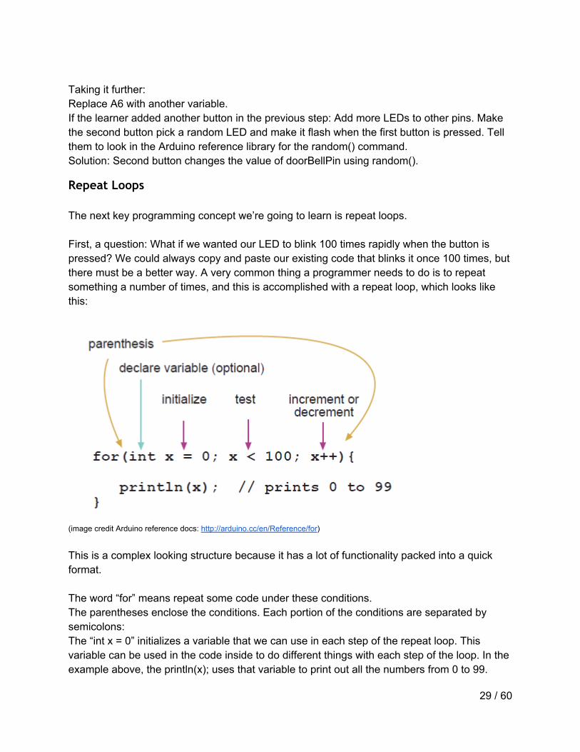
Repeat Loops The next key programming concept we’re going to learn is repeat loops. First, a question: What if we wanted our LED to blink 100 times rapidly when the button is pressed? We could always copy and paste our existing code that blinks it once 100 times, but there must be a better way. A very common thing a programmer needs to do is to repeat something a number of times, and this is accomplished with a repeat loop, which looks like this:
(image credit Arduino reference docs: http://arduino.cc/en/Reference/for) This is a complex looking structure because it has a lot of functionality packed into a quick format. The word “for” means repeat some code under these conditions. The parentheses enclose the conditions. Each portion of the conditions are separated by semicolons: The “int x = 0” initializes a variable that we can use in each step of the repeat loop. This variable can be used in the code inside to do different things with each step of the loop. In the example above, the println(x); uses that variable to print out all the numbers from 0 to 99.
29 / 60

The “x < 100” is the test for when we want the loop to stop. In this case, we stop when x is no longer less than 100, so the last iteration of the loop will have x with a value of 99. The “x++” command tells the loop to increase x by one with each step. Use x-- if you want x to decrease by 1 with each step. Don’t be afraid to look up the reference for it if you don’t remember how to use it! Challenge: So armed with this knowledge, change your code to blink the LED 100 times when the button is pressed. Taking it Further: Be creative! Make multiple LEDs flash in sequence 1-2-3-4-1-2-3-4, etc. Here’s some completed code in case you need a hint. Note that the delays are reduced to make the 100 flashes happen faster: int doorBellPin = A7; void setup() pinMode(doorBellPin, OUTPUT); // Set up pin A7 as an output pinMode(A6, INPUT_PULLUP); //Set up pin A6 as an input void loop() if (digitalRead(A6) == LOW) // The button is connected to GND, which is LOW. Pressing the button changes the input on this pin to LOW for (int i=0; i<100; i++) digitalWrite(doorBellPin, HIGH); // turn the LED on delay(100); // wait for a 1/10th of a second digitalWrite(doorBellPin, LOW); // turn the LED off delay(100); // wait for a 1/10th of a second
Internet Control Now that we know the basics of Arduino coding, it’s time to connect our robot to the Internet! In this section, we will learn how to do this in a few different ways: Listening for events from the Internet, sending variables to the Internet and finally publishing events to the Internet. These form the basic communication building blocks that you can use to program all the interactions between your robot and the Internet.
30 / 60

Listening for Events from the Internet - Spark Functions
In the last exercise, we used the loop() section of our code to continuously monitor the state of a button to see if it had been pressed. This is known as “polling”, and is easy to use for sensors hooked up directly to your robot. But what if you want to trigger some action in your robot from the Internet? We can’t poll the entire Internet looking for interesting things to react to. Instead, we need to set up something that listens for specific messages that are received. We do this by creating a Spark Function. Spark Functions do not live inside your setup() or your loop() section. Instead, they define a brand new section of code that is formatted in the same manner as your setup() and loop() sections. The setup() and loop() are actually functions as well, they are just built-in special functions that get triggered automatically. We’re creating a new function that we will choose when to trigger! All Spark functions follow this format (called “syntax” in programming-speak):
int someKindOfName(String command) // Code goes here
Notice the word “command” in the brackets - our setup() and loop() functions didn’t have that. The word “command” is a variable that you can use to pass additional information to the function from the cloud when we call it. We’ll use it later on to make our doorbell ring in different ways in response to different inputs. Next, need to tell the Spark Cloud about the function so that it can send messages to it. To do this, you add a line to your setup() function:
31 / 60

Spark.function("someKindOfName", someKindOfName);
That’s it! You can set up as many Spark functions as you like, all triggering different actions on your Spark from the cloud. When we call this Spark function remotely, it’s like a message is received that says to the Spark: “We interrupt your regular programming to bring you this important news!”. This stops the execution of whatever it is doing in the loop() section and jumps to the function. After triggering the function, it goes back to the same spot in the loop and continues to execute the loop() as well. Both functions actually happen at the same time, in a similar manner as your computer multitasks and runs several programs at the same time. Here’s the complete version of the the code to activate the doorbell via a remote function call. Teachers, depending on your audience, you can give them this code, or have them figure it out from the code syntax above. int doorBellPin = A7; void setup() pinMode(doorBellPin, OUTPUT); // Set up pin A7 as an output pinMode(A6, INPUT_PULLUP); //Set up pin A6 as an input Spark.function("ringDoorBell", ringDoorBell); void loop() int ringDoorBell (String command) digitalWrite(doorBellPin, HIGH); // turn the LED on delay(1000); // wait for a second digitalWrite(doorBellPin, LOW); // turn the LED off delay(1000); // wait for a second
Send Messages from the Web to Your Spark - Spark Control Panel
32 / 60
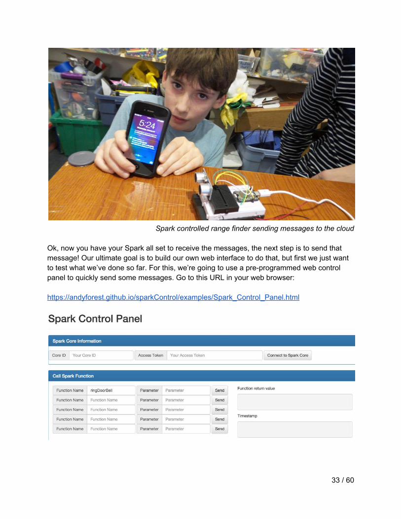
Spark controlled range finder sending messages to the cloud
Ok, now you have your Spark all set to receive the messages, the next step is to send that message! Our ultimate goal is to build our own web interface to do that, but first we just want to test what we’ve done so far. For this, we’re going to use a pre-programmed web control panel to quickly send some messages. Go to this URL in your web browser: https://andyforest.github.io/sparkControl/examples/Spark_Control_Panel.html
33 / 60
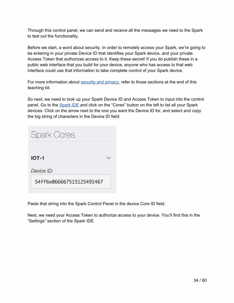
Through this control panel, we can send and receive all the messages we need to the Spark to test out the functionality. Before we start, a word about security. In order to remotely access your Spark, we’re going to be entering in your private Device ID that identifies your Spark device, and your private Access Token that authorizes access to it. Keep these secret! If you do publish these in a public web interface that you build for your device, anyone who has access to that web interface could use that information to take complete control of your Spark device. For more information about security and privacy, refer to those sections at the end of this teaching kit. So next, we need to look up your Spark Device ID and Access Token to input into the control panel. Go to the Spark IDE and click on the “Cores” button on the left to list all your Spark devices. Click on the arrow next to the one you want the Device ID for, and select and copy the big string of characters in the Device ID field:
Paste that string into the Spark Control Panel in the device Core ID field. Next, we need your Access Token to authorize access to your device. You’ll find this in the “Settings” section of the Spark IDE.
34 / 60
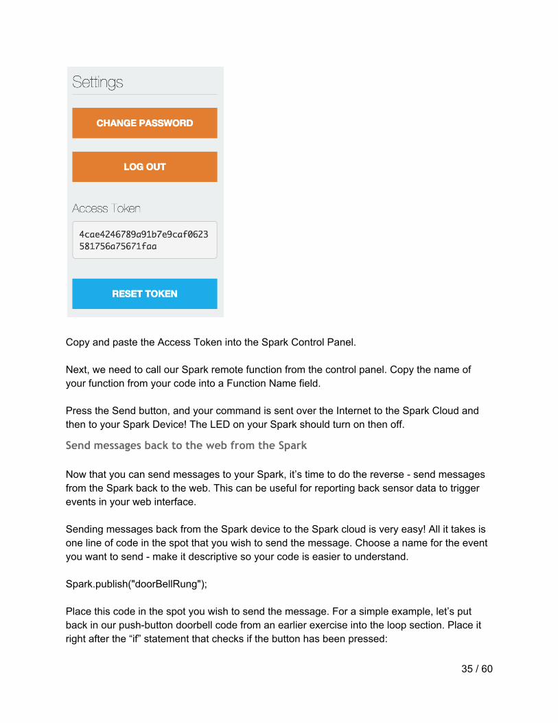
Copy and paste the Access Token into the Spark Control Panel. Next, we need to call our Spark remote function from the control panel. Copy the name of your function from your code into a Function Name field. Press the Send button, and your command is sent over the Internet to the Spark Cloud and then to your Spark Device! The LED on your Spark should turn on then off.
Send messages back to the web from the Spark Now that you can send messages to your Spark, it’s time to do the reverse - send messages from the Spark back to the web. This can be useful for reporting back sensor data to trigger events in your web interface. Sending messages back from the Spark device to the Spark cloud is very easy! All it takes is one line of code in the spot that you wish to send the message. Choose a name for the event you want to send - make it descriptive so your code is easier to understand. Spark.publish("doorBellRung"); Place this code in the spot you wish to send the message. For a simple example, let’s put back in our push-button doorbell code from an earlier exercise into the loop section. Place it right after the “if” statement that checks if the button has been pressed:
35 / 60

int doorBellPin = A7; void setup() pinMode(doorBellPin, OUTPUT); // Set up pin A7 as an output pinMode(A6, INPUT_PULLUP); //Set up pin A6 as an input Spark.function("ringDoorBell", ringDoorBell); void loop() if (digitalRead(A6) == LOW) // The button is connected to GND, which is LOW. Pressing the button changes the input on this pin to LOW Spark.publish("doorBellRung"); digitalWrite(doorBellPin, HIGH); // turn the LED on delay(1000); // wait for a second digitalWrite(doorBellPin, LOW); // turn the LED off delay(1000); // wait for a second int ringDoorBell (String command) digitalWrite(doorBellPin, HIGH); // turn the LED on delay(1000); // wait for a second digitalWrite(doorBellPin, LOW); // turn the LED off delay(1000); // wait for a second
Now open up the Spark Control Panel, and scroll down to the section on “Subscribe to Spark Published Events”, and enter in the name of the event you chose into the “Published Event Name” field. In our case, “doorBellRung”. Press the “Subscribe” button to listen to the events. https://andyforest.github.io/sparkControl/examples/Spark_Control_Panel.html
When you press the button on your Spark device, you will see the result come in on the fields on the right!
36 / 60
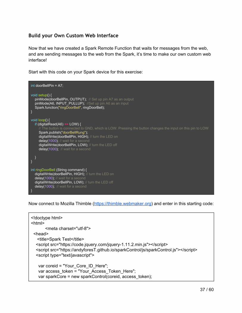
Build your Own Custom Web Interface Now that we have created a Spark Remote Function that waits for messages from the web, and are sending messages to the web from the Spark, it’s time to make our own custom web interface! Start with this code on your Spark device for this exercise: int doorBellPin = A7; void setup() pinMode(doorBellPin, OUTPUT); // Set up pin A7 as an output pinMode(A6, INPUT_PULLUP); //Set up pin A6 as an input Spark.function("ringDoorBell", ringDoorBell); void loop() if (digitalRead(A6) == LOW) // The button is connected to GND, which is LOW. Pressing the button changes the input on this pin to LOW Spark.publish("doorBellRung"); digitalWrite(doorBellPin, HIGH); // turn the LED on delay(1000); // wait for a second digitalWrite(doorBellPin, LOW); // turn the LED off delay(1000); // wait for a second int ringDoorBell (String command) digitalWrite(doorBellPin, HIGH); // turn the LED on delay(1000); // wait for a second digitalWrite(doorBellPin, LOW); // turn the LED off delay(1000); // wait for a second
Now connect to Mozilla Thimble (https://thimble.webmaker.org) and enter in this starting code:
<!doctype html> <html> <meta charset="utf-8"> <head> <title>Spark Test</title> <script src="https://code.jquery.com/jquery-1.11.2.min.js"></script> <script src="https://andyforesT.github.io/sparkControl/js/sparkControl.js"></script> <script type="text/javascript"> var coreid = "Your_Core_ID_Here"; var access_token = "Your_Access_Token_Here"; var sparkCore = new sparkControl(coreid, access_token);
37 / 60

</script> </head> <body>
<p>Spark Control Test</p> <button onclick="sparkCore.callFunction('ringDoorBell', 'Short');">Ring the
DoorBell</button> </body> </html>
The scripts at the top of the page between <head> and </head> need to be included for the code to work. Fill in the correct values for Your_Core_ID_Here and Your_Access_Token_Here. Refer to the Send Messages from the Web to Your Spark - Spark Control Panel section for help finding your Core ID and Access Token. Press the button on the web interface, and see the doorbell ring! The main part that you will now customize is the button itself: <button onclick="sparkCore.callFunction('ringDoorBell', 'Short');">Ring the DoorBell</button> If you want to call a different Spark remote function, just change the ringDoorBell text to your other function call. Copy and paste to make as many buttons as you want! With this basic functionality, you can develop your own web interface. There are plenty of online resources for learning how to program HTML and CSS, the language of web pages. Remixing Mozilla Thimble projects from other people is a great way to get started. Try remixing someone else’s page to add in your spark control buttons. Kahn Academy has some great tutorials for kids and adults. https://www.khanacademy.org/computing/computer-programming/html-css Try building a web interface for the Sample Projects in the section below.
More Internet Control
38 / 60

The Javascript library that makes it simple to access the Spark Commands from a web page will be expanded in the future. Have a look at the SparkControl Library documentation for updates: https://github.com/AndyForest/sparkControl Taking it further: Try adding a command argument to your remote function. Use an if statement to detect this command and ring the doorbell in different ways.
IFTTT IFTTT (If this then that) is an Internet service that lets you connect to different internet events together so that one trigger can create an action on a different internet service. For example, you can make an IFTTT that will automatically text you the weather every morning, save articles from your favorite tweets, or automatically download facebook pictures to dropbox. Spark has its own “Channel” in IFTTT meaning that your events on your Spark can be the trigger for internet actions and that internet triggers can cause actions on your Spark
Setting up Spark with IFTTT Go to IFTTT and click “Join” (if you don’t have an account) or “Sign in” (if you have an account). Once in your account click on “Channels” and Scroll Down to Spark. Click on “Activate” and sign into your Spark.io account. Click “Okay” and you are ready ready to use your Spark with IFTTT. To create a “Recipe”, a connection between one trigger and one action, click on “My Recipes” and click “Create a Recipe”.
Tutorial activity 1: Spark as an Action for a Trigger The next step is to test out if your IFTTT setup works with your Spark. To do this, we must come up with an easy way to trigger the Spark through IFTTT that we can control to test it out. The easiest one to do in a classroom is through Email, though twitter, phone calls, and texts are all easy to trigger if thats easier.
39 / 60
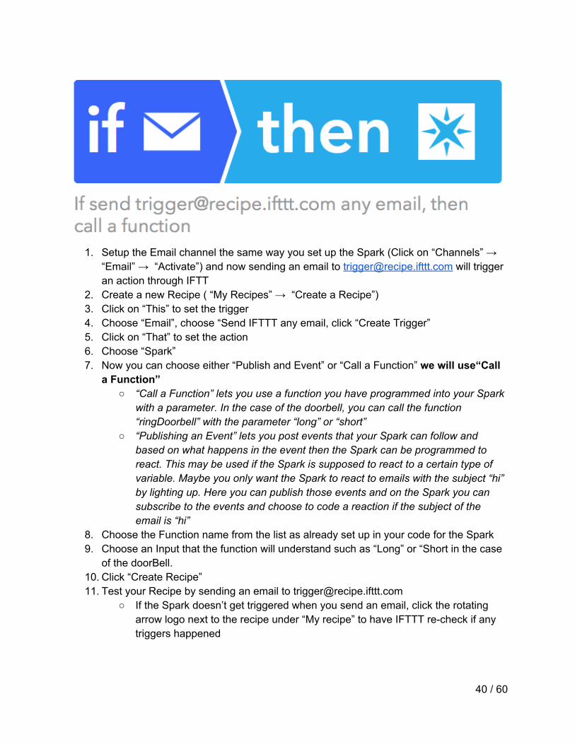
1. Setup the Email channel the same way you set up the Spark (Click on “Channels” →
“Email” → “Activate”) and now sending an email to [email protected] will trigger an action through IFTT
2. Create a new Recipe ( “My Recipes” → “Create a Recipe”) 3. Click on “This” to set the trigger 4. Choose “Email”, choose “Send IFTTT any email, click “Create Trigger” 5. Click on “That” to set the action 6. Choose “Spark” 7. Now you can choose either “Publish and Event” or “Call a Function” we will use“Call
a Function” “Call a Function” lets you use a function you have programmed into your Spark
with a parameter. In the case of the doorbell, you can call the function “ringDoorbell” with the parameter “long” or “short”
“Publishing an Event” lets you post events that your Spark can follow and based on what happens in the event then the Spark can be programmed to react. This may be used if the Spark is supposed to react to a certain type of variable. Maybe you only want the Spark to react to emails with the subject “hi” by lighting up. Here you can publish those events and on the Spark you can subscribe to the events and choose to code a reaction if the subject of the email is “hi”
8. Choose the Function name from the list as already set up in your code for the Spark 9. Choose an Input that the function will understand such as “Long” or “Short in the case
of the doorBell. 10. Click “Create Recipe” 11. Test your Recipe by sending an email to [email protected]
If the Spark doesn’t get triggered when you send an email, click the rotating arrow logo next to the recipe under “My recipe” to have IFTTT re-check if any triggers happened
40 / 60
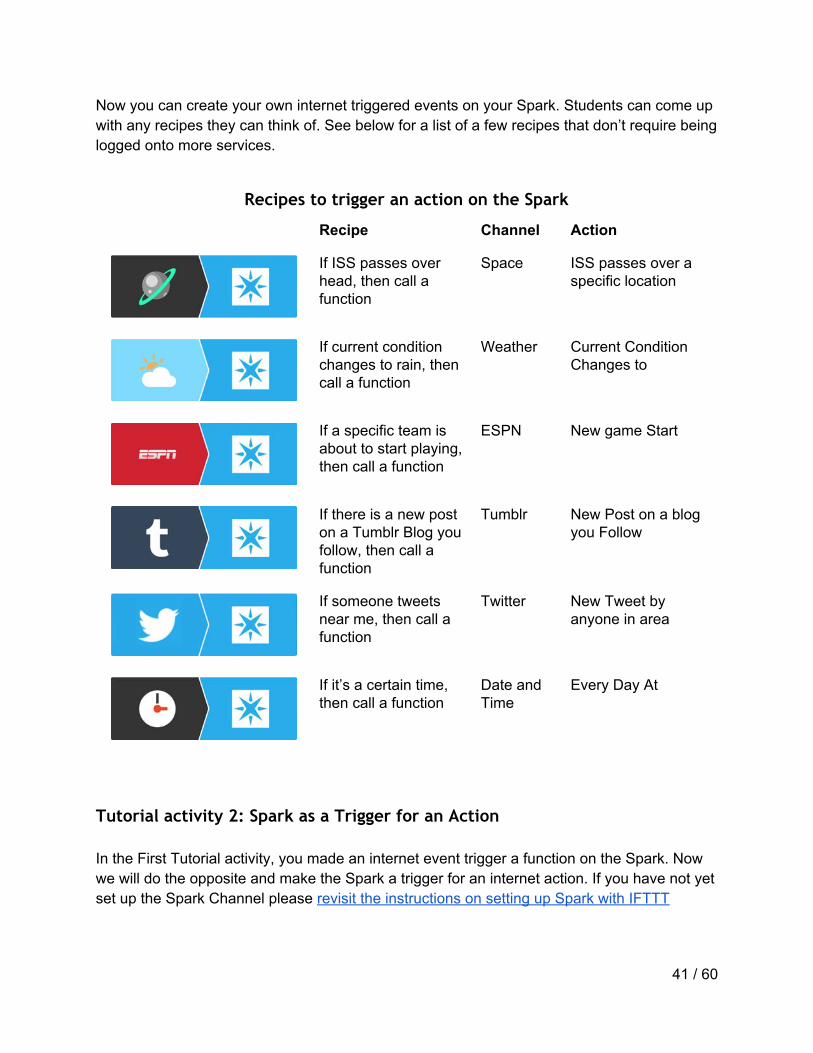
Now you can create your own internet triggered events on your Spark. Students can come up with any recipes they can think of. See below for a list of a few recipes that don’t require being logged onto more services.
Recipes to trigger an action on the Spark
Recipe Channel Action
If ISS passes over head, then call a function
Space ISS passes over a specific location
If current condition changes to rain, then call a function
Weather Current Condition Changes to
If a specific team is about to start playing, then call a function
ESPN New game Start
If there is a new post on a Tumblr Blog you follow, then call a function
Tumblr New Post on a blog you Follow
If someone tweets near me, then call a function
Twitter New Tweet by anyone in area
If it’s a certain time, then call a function
Date and Time
Every Day At
Tutorial activity 2: Spark as a Trigger for an Action In the First Tutorial activity, you made an internet event trigger a function on the Spark. Now we will do the opposite and make the Spark a trigger for an internet action. If you have not yet set up the Spark Channel please revisit the instructions on setting up Spark with IFTTT
41 / 60

To set the Spark as a trigger you must choose it as the “This” in a new recipe
1. Click “My Recipe” and choose “Create a Recipe” 2. Click “This” and choose “Spark 3. Choose one of the Options “New event published”, “Monitor a variable”, “Monitor a
function result”, and “Monitor your device status.” We will use “New event published”
please see the grey text under each option to understand what each does New event published requires a line of code using “.publish” to publish the
event to the internet as talked about earlier 4. Choose the Trigger fields
If (Event Name) - This is the name of the published event such as doorBellRung (Can be left blank)
is (Event Contents) - This is the information contained in the published event such as the timestamp for when an event is triggered (Can be left blank)
Device Name or ID - Choose your device from the list, one Spark account can have more than one device so the drop down menu lets you choose which one you are listening to
5. Choose “That” and decide on an action you would like to happen. To test this we can use the “Email” Channel again.
6. Choose “Email”, click on “Send me an Email”, decide the structure of the email and click “Create Action”
7. Click “Create Recipe” 8. Test your Recipe by ringing the doorbell
If the Spark doesn’t get triggered when you send an email, click the rotating arrow logo next to the recipe under “My recipe” to have IFTTT re-check if any triggers happened
Now you can create your own recipes to trigger internet events with your Spark. Students can come up with any recipes they can think of. See below for a list of a few recipes
42 / 60
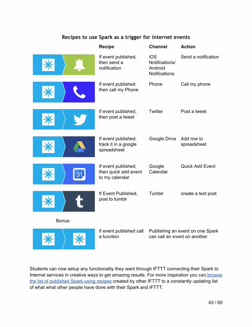
Recipes to use Spark as a trigger for internet events
Recipe Channel Action
If event published, then send a notification
iOS Notifications/Android Notifications
Send a notification
If event published, then call my Phone
Phone Call my phone
If event published, then post a tweet
Twitter Post a tweet
If event published, track it in a google spreadsheet
Google Drive Add row to spreadsheet
If event published, then quick add event to my calendar
Google Calendar
Quick Add Event
If Event Published, post to tumblr
Tumblr create a text post
Bonus:
If event published call a function
Publishing an event on one Spark can call an event on another
Students can now setup any functionality they want through IFTTT connecting their Spark to Internet services in creative ways to get amazing results. For more inspiration you can browse the list of published Spark-using recipes created by other IFTTT to a constantly updating list of what what other people have done with their Spark and IFTTT.
43 / 60

Sample Projects These sample projects are designed to be controlled from their web interface. They send events to the web, and wait for instructions from the web. You can use these sample projects to expand on your knowledge and learn about new sensors, outputs and code to put it all together.
Remote controlled car In this section we will show you how to wire up an rover using an Spark that will be able to drive in different directions and can broadcast information about when it has had a collision.
Parts Mechanical
- 1 Caster Wheel - A Wheel that pivots on its own allowing the car to tear
- 2 Wheels - To go on the DC Motors
- Rectangular base - Something to attach everything too
Electrical - 2 DC Motors
- These two motors will control the two back wheels. A DC motor has two wires that come out of it, if the current goes through the wires in one way, the wheel will turn, and if the current goes through the wires the other way, the wheel will turn the other way
- Solderless Breadboard - This allows for all of the electronic parts to be easily attached together without
soldering - A Breadboard attaches electrical components together by having internal wiring
bridging the electrical connection between holes in which components and wires can be placed.
- Wire - Spark - H-Bridge
- An H-Bridge is an electrical component that allows you to open a switch using a spark. You can it use as a switch between a battery to an output (like a motor), and use the Spark to flip the switch to open up the circuit. An H-bridge has 4 of
44 / 60

these switch in it meaning you can control both wires coming out of both motors with one H-Bridge
- 6 AA Battery Pack - 2 Buttons
- To detect collisions
Wiring The Electronics
Above is a diagram for the rover circuity. There are three main parts: the motors, the buttons, and the power.
45 / 60
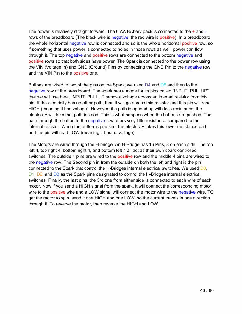
The power is relatively straight forward. The 6 AA BAttery pack is connected to the + and - rows of the breadboard (The black wire is negative, the red wire is positive). In a breadboard the whole horizontal negative row is connected and so is the whole horizontal positive row, so if something that uses power is connected to holes in those rows as well, power can flow through it. The top negative and positive rows are connected to the bottom negative and positive rows so that both sides have power. The Spark is connected to the power row using the VIN (Voltage In) and GND (Ground) Pins by connecting the GND Pin to the negative row and the VIN Pin to the positive one. Buttons are wired to two of the pins on the Spark, we used D4 and D5 and then to the negative row of the breadboard. The spark has a mode for its pins called “INPUT_PULLUP” that we will use here. INPUT_PULLUP sends a voltage across an internal resistor from this pin. If the electricity has no other path, than it will go across this resistor and this pin will read HIGH (meaning it has voltage). However, if a path is opened up with less resistance, the electricity will take that path instead. This is what happens when the buttons are pushed. The path through the button to the negative row offers very little resistance compared to the internal resistor. When the button is pressed, the electricity takes this lower resistance path and the pin will read LOW (meaning it has no voltage). The Motors are wired through the H-bridge. An H-Bridge has 16 Pins, 8 on each side. The top left 4, top right 4, bottom right 4, and bottom left 4 all act as their own spark controlled switches. The outside 4 pins are wired to the positive row and the middle 4 pins are wired to the negative row. The Second pin in from the outside on both the left and right is the pin connected to the Spark that control the H-Bridges internal electrical switches. We used D0, D1, D2, and D3 as the Spark pins designated to control the H-Bridges internal electrical switches. Finally, the last pins, the 3rd one from either side is connected to each wire of each motor. Now if you send a HIGH signal from the spark, it will connect the corresponding motor wire to the positive wire and a LOW signal will connect the motor wire to the negative wire. TO get the motor to spin, send it one HIGH and one LOW, so the current travels in one direction through it. To reverse the motor, then reverse the HIGH and LOW.
46 / 60

47 / 60

(Constructed rover, battery cables not plugged into breadboard)
Spark Code The code involves creating a function called roverDrive that will be able to tell the rover to go forward, back, left, right, or to stop by sending different signals along the 4 pins connected to the Spark. You can then use the web interface to send functions into the rover so that it travels the direction you would like. The Rover also has two buttons, one on either side of its front to detect collisions and react to them. It is programed to publish an event when it detects a collision and to back up and turn to avoid it.
48 / 60

One seemingly complicated area of the code is something called debouncing. When a button is pressed, for a fraction of a second it is continually gaining and losing connection resulting in noise. We want the rover to only react when it has pushed a button and not when its shaking has accidentally resulted in a momentary contact. To debounce the button, the code remembers the last button state (pushed or not pushed). It then checks to see if the this button state is different from the last button state (Is it now pushed when it was not pushed before or vice versa). If the button has changed states, it starts a timer. If that timer counts longer than the the debounceDelay (an arbitrary program number to correct for noise) then it knows the button has been pushed. In this case debounceDelay is set to 50 so if the button is pushed for 50 milliseconds, the program considers this to be pushed, publishes the collision, and react accordingly. /* Rover.ino Control a robot rover By Andy Forest and Daniel Rother of MakerKids */ // We set variables for the pins connected to each wheel. // You can change the pin numbers depending on where the motor leads are plugged into your board. int leftMotorPin1 = D2; int leftMotorPin2 = D3; int rightMotorPin1 = D0; int rightMotorPin2 = D1; int leftButtonPin = D5; int rightButtonPin = D4; // Store the last direction moved. f = forward, b = back, s = stopped const char* roverMovingDirection = "s"; // Variables will change: int rightButtonState; // the current reading from the input pin int leftButtonState; // the current reading from the input pin int lastRightButtonState = LOW; // the previous reading from the input pin int lastLeftButtonState = LOW; // the previous reading from the input pin // the following variables are long's because the time, measured in miliseconds, // will quickly become a bigger number than can be stored in an int. long lastRightDebounceTime = 0; // the last time the Right input pin was toggled long lastLeftDebounceTime = 0; // the last time the Left input pin was toggled long debounceDelay = 50; // the debounce time; increase if the output flickers //Create function to define what to do to each motor pin when told to go in a specific direction
49 / 60

int roverDrive (String direction) if (direction == "forward" || direction == "f") // By setting one motor pin high and the other low, the motor turns on. digitalWrite(leftMotorPin1, HIGH); digitalWrite(leftMotorPin2, LOW); digitalWrite(rightMotorPin1, HIGH); digitalWrite(rightMotorPin2, LOW); roverMovingDirection = "f"; return 1; else if (direction == "back" || direction == "b") // Reverse direction by switching the HIGH and LOW digitalWrite(leftMotorPin1, LOW); digitalWrite(leftMotorPin2, HIGH); digitalWrite(rightMotorPin1, LOW); digitalWrite(rightMotorPin2, HIGH); roverMovingDirection = "b"; return 2; else if (direction == "right" || direction == "r") // Change direction by turning on the motor on one side only digitalWrite(leftMotorPin1, HIGH); digitalWrite(leftMotorPin2, LOW); digitalWrite(rightMotorPin1, LOW); digitalWrite(rightMotorPin2, LOW); delay(1000); roverDrive(roverMovingDirection); return 3; else if (direction == "left" || direction == "l") // Change direction by turning on the motor on one side only digitalWrite(leftMotorPin1, LOW); digitalWrite(leftMotorPin2, LOW); digitalWrite(rightMotorPin1, HIGH); digitalWrite(rightMotorPin2, LOW); delay(1000); roverDrive(roverMovingDirection); return 4; else if (direction == "stop" || direction == "s") // Stop by turning off both motors digitalWrite(leftMotorPin1, LOW); digitalWrite(leftMotorPin2, LOW); digitalWrite(rightMotorPin1, LOW); digitalWrite(rightMotorPin2, LOW); roverMovingDirection = "s"; return 0; // This routine runs only once upon reset void setup()
50 / 60
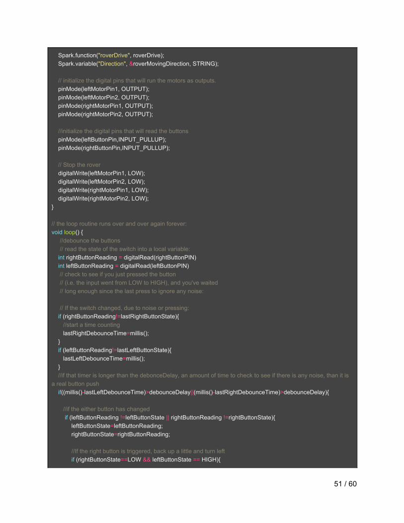
Spark.function("roverDrive", roverDrive); Spark.variable("Direction", &roverMovingDirection, STRING); // initialize the digital pins that will run the motors as outputs. pinMode(leftMotorPin1, OUTPUT); pinMode(leftMotorPin2, OUTPUT); pinMode(rightMotorPin1, OUTPUT); pinMode(rightMotorPin2, OUTPUT); //initialize the digital pins that will read the buttons pinMode(leftButtonPin,INPUT_PULLUP); pinMode(rightButtonPin,INPUT_PULLUP); // Stop the rover digitalWrite(leftMotorPin1, LOW); digitalWrite(leftMotorPin2, LOW); digitalWrite(rightMotorPin1, LOW); digitalWrite(rightMotorPin2, LOW); // the loop routine runs over and over again forever: void loop() //debounce the buttons // read the state of the switch into a local variable: int rightButtonReading = digitalRead(rightButtonPIN) int leftButtonReading = digitalRead(leftButtonPIN) // check to see if you just pressed the button // (i.e. the input went from LOW to HIGH), and you've waited // long enough since the last press to ignore any noise: // If the switch changed, due to noise or pressing: if (rightButtonReading!=lastRightButtonState) //start a time counting lastRightDebounceTime=millis(); if (leftButtonReading!=lastLeftButtonState) lastLeftDebounceTime=millis(); //if that timer is longer than the debonceDelay, an amount of time to check to see if there is any noise, than it is a real button push if((millis()-lastLeftDebounceTime)>debounceDelay||(millis()-lastRightDebounceTime)>debounceDelay) //if the either button has changed if (leftButtonReading !=leftButtonState || rightButtonReading !=rightButtonState) leftButtonState=leftButtonReading; rightButtonState=rightButtonReading; //If the right button is triggered, back up a little and turn left if (rightButtonState==LOW && leftButtonState == HIGH)
51 / 60
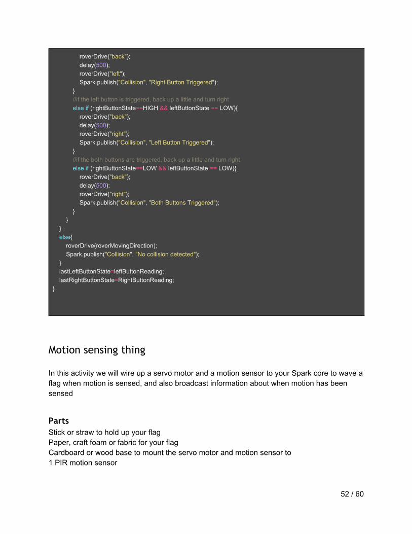
roverDrive("back"); delay(500); roverDrive("left"); Spark.publish("Collision", "Right Button Triggered"); //if the left button is triggered, back up a little and turn right else if (rightButtonState==HIGH && leftButtonState == LOW) roverDrive("back"); delay(500); roverDrive("right"); Spark.publish("Collision", "Left Button Triggered"); //if the both buttons are triggered, back up a little and turn right else if (rightButtonState==LOW && leftButtonState == LOW) roverDrive("back"); delay(500); roverDrive("right"); Spark.publish("Collision", "Both Buttons Triggered"); else roverDrive(roverMovingDirection); Spark.publish("Collision", "No collision detected"); lastLeftButtonState=leftButtonReading; lastRightButtonState=RightButtonReading;
Motion sensing thing In this activity we will wire up a servo motor and a motion sensor to your Spark core to wave a flag when motion is sensed, and also broadcast information about when motion has been sensed
Parts Stick or straw to hold up your flag Paper, craft foam or fabric for your flag Cardboard or wood base to mount the servo motor and motion sensor to 1 PIR motion sensor
52 / 60

- PIR stands for “passive infrared”. This type of sensor allows us to sense motion, for example, whether a person has moved into our out of the range of the sensor.
Servo motor - This type of motor can be set to turn to a specific position based on an angle. The
position of the motor is determined by the length of an electric pulse. Most servos only turn to about 180 degrees, but there are also continuous rotation servos that rotate a full 360 degrees.
Wire Spark core
Wiring Power Similar to previous examples, we start by using a wire to connect the 3.3V pin on the Spark to the positive power rail on the breadboard, and the GND pin on the Spark to the negative power rail on the breadboard. Servo The servo motor has three leads. Depending on the servo motor you have, the colors might be a bit different. The red lead is always power, and GND will be black or brown. The third lead is the control or signal lead, which will be orange, yellow or white. The end of these servo wires have a connector end which we can push wires into to connect it to our breadboard and Spark. Connect a wire from the connector leading to the power lead on the servo to the positive power rail on the breadboard. Connect a second wire to the connector leading to the negative lead on the servo to the negative power rail on the breadboard. Connect a third wire to the connector leading to the control lead on the servo to pin D0 on the Spark. Motion sensor Most PIR motion sensors have a 3 pin connection similar to what you saw on the Servo motor. The pins might be different between different sensors purchased from different companies, so make sure you check the information for yours! One pin will be ground, one will be power, and one will be control. Connect a wire from the ground pin to the negative power rail on the breadboard. Connect a second wire from the power pin to the positive power rail on the breadboard. Connect a third wire from the control pin to pin D1 on the Spark.
53 / 60

54 / 60

Spark Code Servo myservo; // create servo object to control a servo // digital pin 1 has a motionSensor attached to it. Give it a name: int motionSensorPin = D1; void setup() myservo.attach(D0); // attaches the servo on pin 0 to the servo object pinMode(motionSensorPin, INPUT); Spark.function("waveFlag", waveFlag); Spark.variable("motionSensorPin", &motionSensorPin, INT); void loop() // digitalRead reads the input pin - it checks if motionSensorPin (the pin the motion sensor is plugged into) is sensing a 1 or a 0. This information is stored in motionSensorState
55 / 60

int motionSensorState = digitalRead(motionSensorPin); if(motionSensorState==HIGH) Spark.publish("motionSensed"); delay(200); int waveFlag(String command) if(command == "Short") Spark.publish("flagWaving","Short"); myservo.write(45); // tell servo to go to position delay(500); // waits 1 second myservo.write(135); delay(500); myservo.write(45); delay(500); myservo.write(135); delay(500); if(command == "Long") Spark.publish("flagWaving","Long"); for (int i=0; i<10; i++) myservo.write(45); // tell servo to go to position delay(500); // waits 1 second myservo.write(135); delay(500);
Taking it Further
Security The web examples in this teaching kit use your own unique Access_Token to authorize them to access your Spark device. Unfortunately, this Access Token can be used to upload new code to your device, and control it in every way.
56 / 60

Ensure that you are only publishing these web interfaces privately to people you trust, as they could take over your Spark. Future versions of the Spark API will have support for public remote functions and published events. This will make it possible to build web interfaces for just the functionality you want to expose. Keep an eye on the Spark community forums for announcements.
Privacy When you use an Internet connected device, where does your data go? Who has access to that data? We live in the age of Facebook, we’re used to publishing many details about our lives for the world to see. Facebook helps us connect and communicate with our friends. Facebook helps us find out about what’s important to them, and what’s going on in the world. Who owns all the data you send to Facebook? What is it used for? Facebook’s business model is based on selling your data to advertisers. You use the site for free, and they sell ads on the site. These ads are targeted to you based on the information that you have shared with them. You are their product, not their customer. Who’s interests do you think that would make them keep first in mind? Think about how Facebook implements changes to their privacy policy: several times they have modified it to make it more permissive about the ways they will use your data, and each time they have made it difficult or confusing to opt out. One of the reason that so many companies are excited about the Internet of Things is the new possibilities that it opens up for data collection and processing. Information about your daily jog can be used to fine tune your workout. Information about your fridge contents can help you choose recipes and make a grocery list. Who should own this information? If a company owns it, they are peering into your life with a new level of intimacy. They can market things to you based on the tiny details of what you do all day. If you own it yourself, you can decide what is done with it. The best way to preserve this ownership and privacy control is to have full control over the device! This starts with a privacy policy that identifies you as the owner of your own data, and requires your permission to use that data for any purpose. Many companies such as Nest that make the Internet connected thermostat have privacy policies that sound pretty good:
57 / 60

Under no circumstance do we share personal information for any commercial or marketing purpose unrelated to the delivery of Nest Products and services without asking you first.
However, it then goes on to state:
We may share non-personal information (for example, aggregated or anonymized customer data) publicly and with our partners.
Anonymized sounds good, doesn’t it? If they can’t identify you, what’s the harm? The first problem is that there has been a lot of research that has shown that data such as this can be de-anonymized. If your IoT devices are tracking data in detail, your habits will serve as a personal fingerprint. For example, Netflix published anonymous data of millions of their users’ movie queues as part of a campaign to improve its movie recommendation system. In a 2008 University of Texas–Austin study, they were actually able to identify a significant number of the “anonymous” people from this information alone! Once they zero in on your fingerprint, all the marketers need is one personal connection to re-link you to your whole dataset. Ever use a credit card to buy something? Anything with your name on it can link up all your data. The second problem is that you have to trust the company that makes your IoT device to tell you what data it is collecting about you. Time and time again, companies have been caught collecting more data than they said they would. The biggest flashlight app in the Android app store was caught collecting users GPS locations and sharing them with advertisers. They’ll get better and better at covering their tracks, it’s in their best interest. Even when they’re honest, companies can sneak in data collection under the guise of offering you something else. Nest for example:
This information may also be shared with other users to help them better understand their energy usage compared to others in the Nest community, raise awareness about safety issues, or help us generally improve our system.
Sharing data to “generally improve our system” gives them a pretty wide reach. The third problem is lock-in. Once a company gets big enough and popular enough, they can introduce changes without fear of people switching to another platform. If Nest suddenly changes their privacy policy in a way you don’t like, what’s your alternative? Throw it away and buy a new one from a company with a privacy policy you like?
58 / 60
These three problems are all solved by Open Source, which makes it vital to choose and promote Open Source Internet of Things solutions. An Open Source IoT solution consists first of open hardware. This means that the physical devices are documented and licensed in a way that anyone can make their own. An Open Source IoT solution must also include open software. This means that all the software components must have their source code available and licensed in a way that anyone can use them. Open Source means that YOU always have control all the way from your device to the cloud server that controls and communicates with it. It means that if you wanted to, you could set up your own private cloud, and keep all your data completely under your control. Having this open-source option available also serves as a safeguard against privacy policy changes. If a company makes unwelcome privacy changes, it’s a simple matter of someone setting up a private server with more strict controls. For these reasons, we have chosen the Spark platform for this Internet of Things teaching kit. Spark’s commitment to Open Source hardware and software ensures that Internet of Things devices are developed with the user first in mind! Copyright (c) 2015 MakerKids Inc. Permission is hereby granted, free of charge, to any person obtaining a copy of this software and associated documentation files (the "Software"), to deal in the Software without restriction, including without limitation the rights to use, copy, modify, merge, publish, distribute, sublicense, and/or sell copies of the Software, and to permit persons to whom the Software is furnished to do so, subject to the following conditions: The above copyright notice and this permission notice shall be included in all copies or substantial portions of the Software. THE SOFTWARE IS PROVIDED "AS IS", WITHOUT WARRANTY OF ANY KIND, EXPRESS OR IMPLIED, INCLUDING BUT NOT LIMITED TO THE WARRANTIES OF MERCHANTABILITY, FITNESS FOR A PARTICULAR PURPOSE AND NONINFRINGEMENT. IN NO EVENT SHALL THE AUTHORS OR COPYRIGHT HOLDERS BE LIABLE FOR ANY CLAIM, DAMAGES OR OTHER LIABILITY, WHETHER IN AN ACTION OF CONTRACT, TORT OR OTHERWISE, ARISING FROM, OUT OF OR IN CONNECTION WITH THE SOFTWARE OR THE USE OR OTHER DEALINGS IN THE SOFTWARE.
59 / 60

60 / 60