spacewire cable and connector variations...with awg 26 spacewire cable gsc-05-82730-00 eye pattern...
TRANSCRIPT
Page 1
SPACEWIRE CABLE AND
CONNECTOR VARIATIONS
Shaune S. AllenNASA Goddard Space Flight Center, Greenbelt, MD, 20771
E-mail: [email protected]
Page 2
SpaceWire Connector Issues
Connector Specification
– SpaceWire connectors have known issues
- Not impedance-matched to the cable
- Handling (mechanical) issues
– Need space-qualified matched impedance connector
- alternative space-qualified connector
– Electrical Issues
- Only a single ground pin
- Inner shield does not pass through bulkhead
- Near-end Crosstalk (NEXT) at the SpaceWire connector
Cable Specification
– Use of larger gauge cable in non-standard applications or to meet tight specifications
Page 3
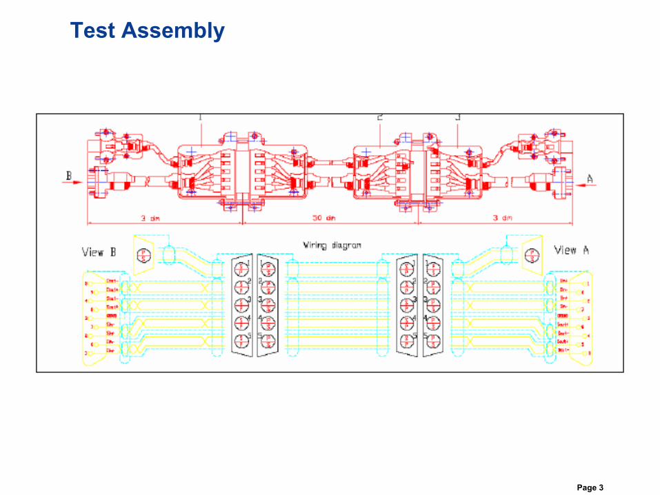
Test Assembly
Page 4
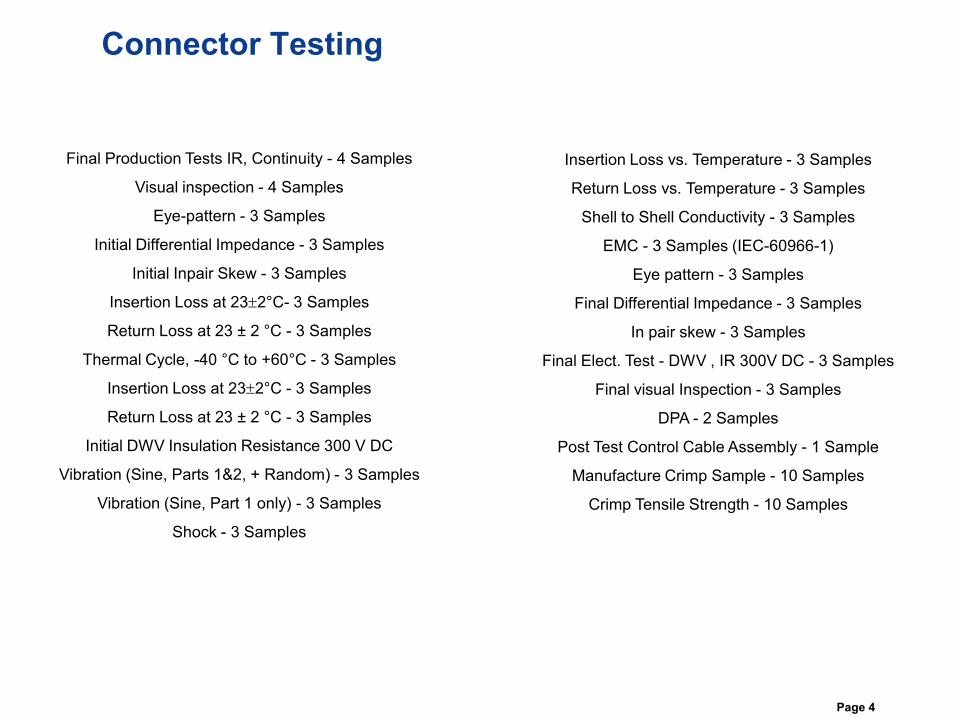
Connector Testing
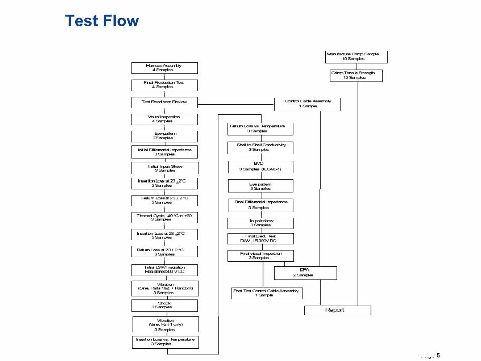
Final Production Tests IR, Continuity - 4 Samples
Visual inspection - 4 Samples
Eye-pattern - 3 Samples
Initial Differential Impedance - 3 Samples
Initial Inpair Skew - 3 Samples
Insertion Loss at 232°C- 3 Samples
Return Loss at 23 ± 2 °C - 3 Samples
Thermal Cycle, -40 °C to +60°C - 3 Samples
Insertion Loss at 232°C - 3 Samples
Return Loss at 23 ± 2 °C - 3 Samples
Initial DWV Insulation Resistance 300 V DC
Vibration (Sine, Parts 1&2, + Random) - 3 Samples
Vibration (Sine, Part 1 only) - 3 Samples
Shock - 3 Samples
Insertion Loss vs. Temperature - 3 Samples
Return Loss vs. Temperature - 3 Samples
Shell to Shell Conductivity - 3 Samples
EMC - 3 Samples (IEC-60966-1)
Eye pattern - 3 Samples
Final Differential Impedance - 3 Samples
In pair skew - 3 Samples
Final Elect. Test - DWV , IR 300V DC - 3 Samples
Final visual Inspection - 3 Samples
DPA - 2 Samples
Post Test Control Cable Assembly - 1 Sample
Manufacture Crimp Sample - 10 Samples
Crimp Tensile Strength - 10 Samples
Page 5
Test Flow
Page 6
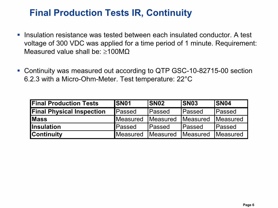
Final Production Tests IR, Continuity
Insulation resistance was tested between each insulated conductor. A test
voltage of 300 VDC was applied for a time period of 1 minute. Requirement:
Measured value shall be: 100MΩ
Continuity was measured out according to QTP GSC-10-82715-00 section
6.2.3 with a Micro-Ohm-Meter. Test temperature: 22°C
Final Production Tests SN01 SN02 SN03 SN04
Final Physical Inspection Passed Passed Passed Passed
Mass Measured Measured Measured Measured
Insulation Passed Passed Passed Passed
Continuity Measured Measured Measured Measured
Page 7
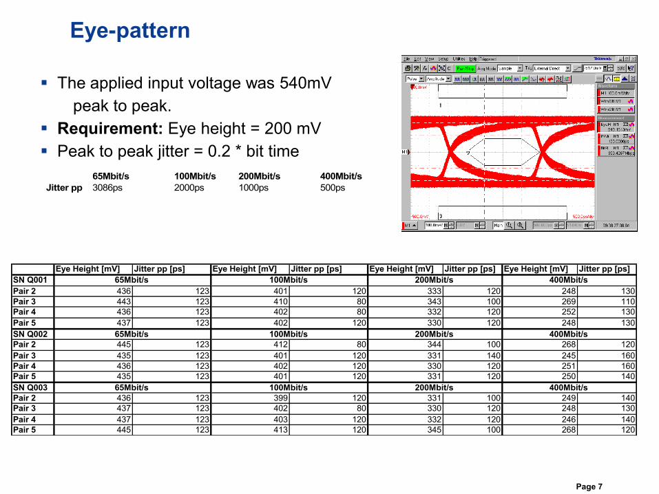
Eye-pattern
The applied input voltage was 540mV
peak to peak.
Requirement: Eye height = 200 mV
Peak to peak jitter = 0.2 * bit time
65Mbit/s 100Mbit/s 200Mbit/s 400Mbit/s
Jitter pp 3086ps 2000ps 1000ps 500ps
Eye Height [mV] Jitter pp [ps] Eye Height [mV] Jitter pp [ps] Eye Height [mV] Jitter pp [ps] Eye Height [mV] Jitter pp [ps]
SN Q001
Pair 2 436 123 401 120 333 120 248 130
Pair 3 443 123 410 80 343 100 269 110
Pair 4 436 123 402 80 332 120 252 130
Pair 5 437 123 402 120 330 120 248 130
SN Q002
Pair 2 445 123 412 80 344 100 268 120
Pair 3 435 123 401 120 331 140 245 160
Pair 4 436 123 402 120 330 120 251 160
Pair 5 435 123 401 120 331 120 250 140
SN Q003
Pair 2 436 123 399 120 331 100 249 140
Pair 3 437 123 402 80 330 120 248 130
Pair 4 437 123 403 120 332 120 246 140
Pair 5 445 123 413 120 345 100 268 120
400Mbit/s
100Mbit/s
65Mbit/s 200Mbit/s
65Mbit/s
100Mbit/s
200Mbit/s 400Mbit/s
65Mbit/s 100Mbit/s 200Mbit/s 400Mbit/s
Page 8
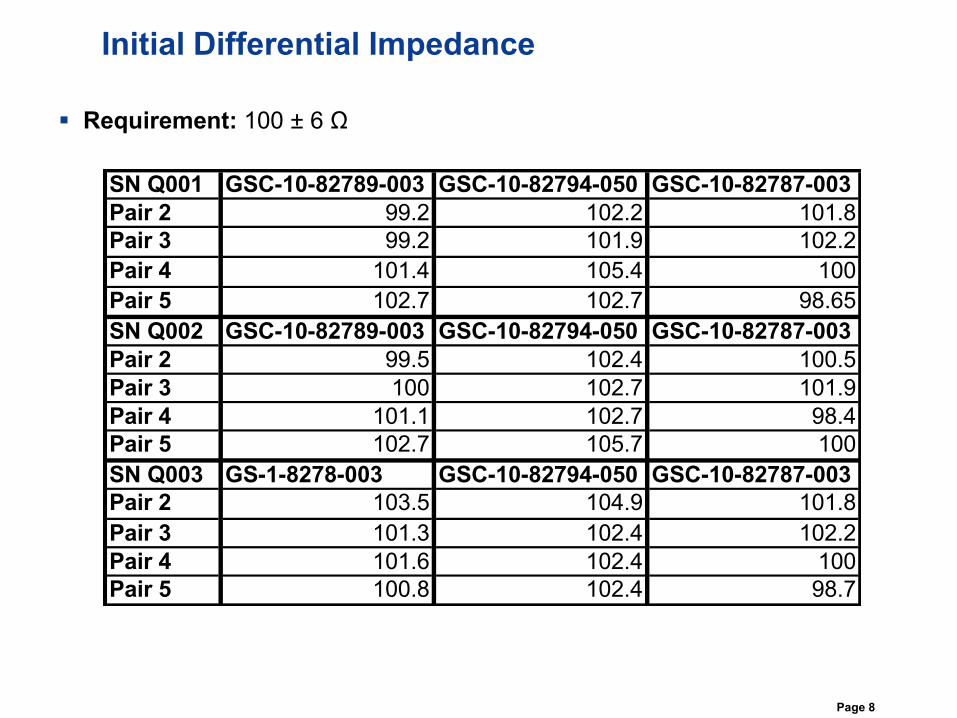
Initial Differential Impedance
Requirement: 100 ± 6 Ω
SN Q001 GSC-10-82789-003 GSC-10-82794-050 GSC-10-82787-003
Pair 2 99.2 102.2 101.8
Pair 3 99.2 101.9 102.2
Pair 4 101.4 105.4 100
Pair 5 102.7 102.7 98.65
SN Q002 GSC-10-82789-003 GSC-10-82794-050 GSC-10-82787-003
Pair 2 99.5 102.4 100.5
Pair 3 100 102.7 101.9
Pair 4 101.1 102.7 98.4
Pair 5 102.7 105.7 100
SN Q003 GS-1-8278-003 GSC-10-82794-050 GSC-10-82787-003
Pair 2 103.5 104.9 101.8
Pair 3 101.3 102.4 102.2
Pair 4 101.6 102.4 100
Pair 5 100.8 102.4 98.7
Page 9
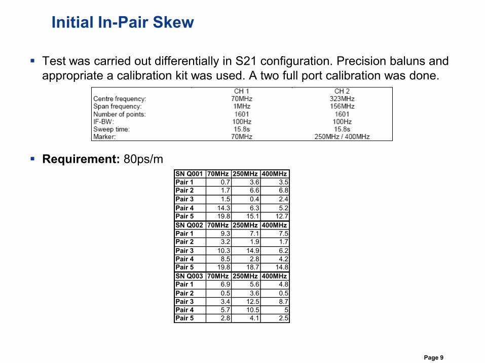
Initial In-Pair Skew
Test was carried out differentially in S21 configuration. Precision baluns and
appropriate a calibration kit was used. A two full port calibration was done.
Requirement: 80ps/mSN Q001 70MHz 250MHz 400MHz
Pair 1 0.7 3.6 3.5
Pair 2 1.7 6.6 6.8
Pair 3 1.5 0.4 2.4
Pair 4 14.3 6.3 5.2
Pair 5 19.8 15.1 12.7
SN Q002 70MHz 250MHz 400MHz
Pair 1 9.3 7.1 7.5
Pair 2 3.2 1.9 1.7
Pair 3 10.3 14.9 6.2
Pair 4 8.5 2.8 4.2
Pair 5 19.8 18.7 14.8
SN Q003 70MHz 250MHz 400MHz
Pair 1 6.9 5.6 4.8
Pair 2 0.5 3.6 0.5
Pair 3 3.4 12.5 8.7
Pair 4 5.7 10.5 5
Pair 5 2.8 4.1 2.5
Page 10
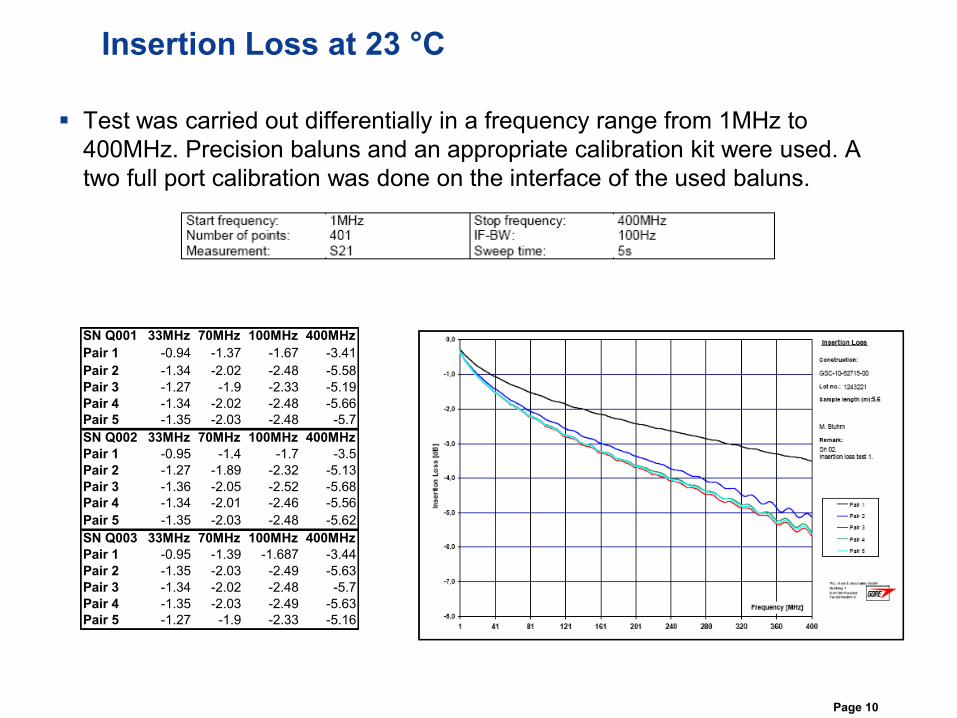
Insertion Loss at 23 °C
Test was carried out differentially in a frequency range from 1MHz to
400MHz. Precision baluns and an appropriate calibration kit were used. A
two full port calibration was done on the interface of the used baluns.
SN Q001 33MHz 70MHz 100MHz 400MHz
Pair 1 -0.94 -1.37 -1.67 -3.41
Pair 2 -1.34 -2.02 -2.48 -5.58
Pair 3 -1.27 -1.9 -2.33 -5.19
Pair 4 -1.34 -2.02 -2.48 -5.66
Pair 5 -1.35 -2.03 -2.48 -5.7
SN Q002 33MHz 70MHz 100MHz 400MHz
Pair 1 -0.95 -1.4 -1.7 -3.5
Pair 2 -1.27 -1.89 -2.32 -5.13
Pair 3 -1.36 -2.05 -2.52 -5.68
Pair 4 -1.34 -2.01 -2.46 -5.56
Pair 5 -1.35 -2.03 -2.48 -5.62
SN Q003 33MHz 70MHz 100MHz 400MHz
Pair 1 -0.95 -1.39 -1.687 -3.44
Pair 2 -1.35 -2.03 -2.49 -5.63
Pair 3 -1.34 -2.02 -2.48 -5.7
Pair 4 -1.35 -2.03 -2.49 -5.63
Pair 5 -1.27 -1.9 -2.33 -5.16
Page 11
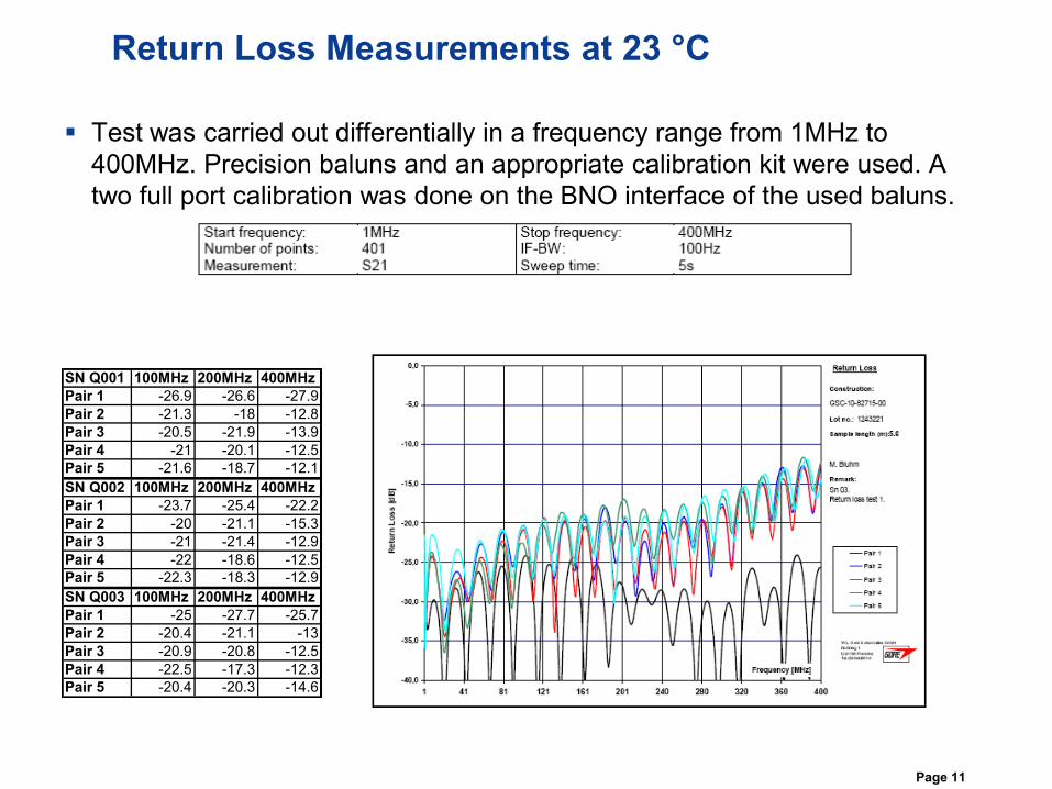
Return Loss Measurements at 23 °C
Test was carried out differentially in a frequency range from 1MHz to
400MHz. Precision baluns and an appropriate calibration kit were used. A
two full port calibration was done on the BNO interface of the used baluns.
SN Q001 100MHz 200MHz 400MHz
Pair 1 -26.9 -26.6 -27.9
Pair 2 -21.3 -18 -12.8
Pair 3 -20.5 -21.9 -13.9
Pair 4 -21 -20.1 -12.5
Pair 5 -21.6 -18.7 -12.1
SN Q002 100MHz 200MHz 400MHz
Pair 1 -23.7 -25.4 -22.2
Pair 2 -20 -21.1 -15.3
Pair 3 -21 -21.4 -12.9
Pair 4 -22 -18.6 -12.5
Pair 5 -22.3 -18.3 -12.9
SN Q003 100MHz 200MHz 400MHz
Pair 1 -25 -27.7 -25.7
Pair 2 -20.4 -21.1 -13
Pair 3 -20.9 -20.8 -12.5
Pair 4 -22.5 -17.3 -12.3
Pair 5 -20.4 -20.3 -14.6
Page 12
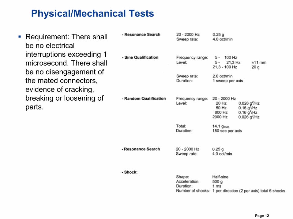
Physical/Mechanical Tests
Requirement: There shall
be no electrical
interruptions exceeding 1
microsecond. There shall
be no disengagement of
the mated connectors,
evidence of cracking,
breaking or loosening of
parts.
Page 13
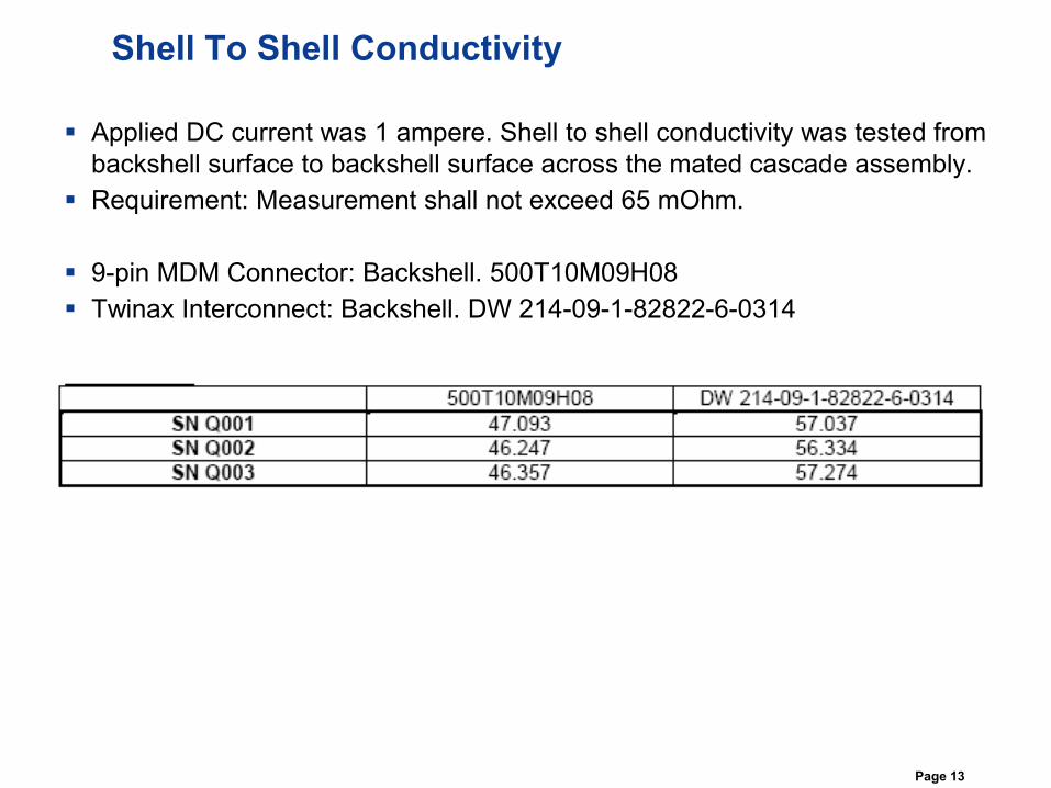
Shell To Shell Conductivity
Applied DC current was 1 ampere. Shell to shell conductivity was tested from
backshell surface to backshell surface across the mated cascade assembly.
Requirement: Measurement shall not exceed 65 mOhm.
9-pin MDM Connector: Backshell. 500T10M09H08
Twinax Interconnect: Backshell. DW 214-09-1-82822-6-0314
Page 14
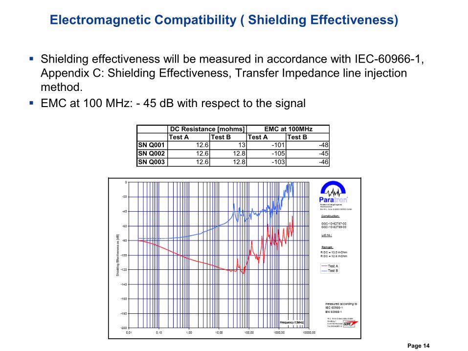
Electromagnetic Compatibility ( Shielding Effectiveness)
Shielding effectiveness will be measured in accordance with IEC-60966-1,
Appendix C: Shielding Effectiveness, Transfer Impedance line injection
method.
EMC at 100 MHz: - 45 dB with respect to the signal
Test A Test B Test A Test B
SN Q001 12.6 13 -101 -48
SN Q002 12.6 12.8 -105 -45
SN Q003 12.6 12.8 -103 -46
DC Resistance [mohms] EMC at 100MHz
Page 15
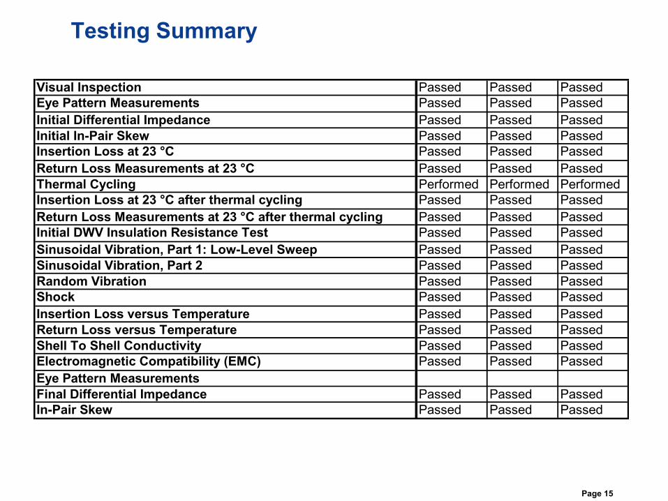
Testing Summary
Visual Inspection Passed Passed Passed
Eye Pattern Measurements Passed Passed Passed
Initial Differential Impedance Passed Passed Passed
Initial In-Pair Skew Passed Passed Passed
Insertion Loss at 23 °C Passed Passed Passed
Return Loss Measurements at 23 °C Passed Passed Passed
Thermal Cycling Performed Performed Performed
Insertion Loss at 23 °C after thermal cycling Passed Passed Passed
Return Loss Measurements at 23 °C after thermal cycling Passed Passed Passed
Initial DWV Insulation Resistance Test Passed Passed Passed
Sinusoidal Vibration, Part 1: Low-Level Sweep Passed Passed Passed
Sinusoidal Vibration, Part 2 Passed Passed Passed
Random Vibration Passed Passed Passed
Shock Passed Passed Passed
Insertion Loss versus Temperature Passed Passed Passed
Return Loss versus Temperature Passed Passed Passed
Shell To Shell Conductivity Passed Passed Passed
Electromagnetic Compatibility (EMC) Passed Passed Passed
Eye Pattern Measurements
Final Differential Impedance Passed Passed Passed
In-Pair Skew Passed Passed Passed
Page 16
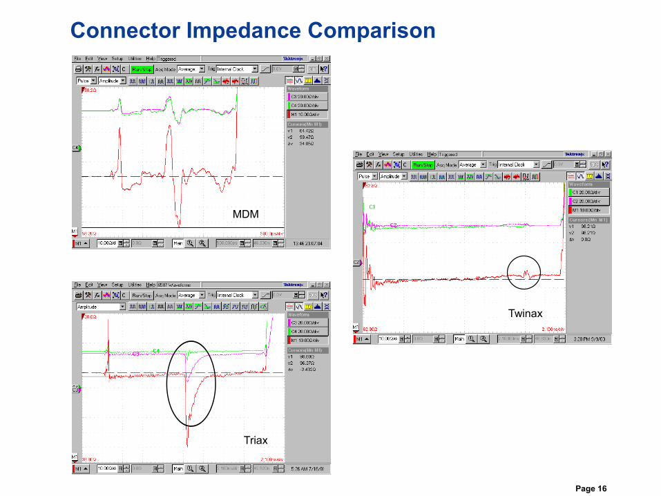
Connector Impedance Comparison
Micro D-Sub
Twinax
MDM
Triax
Page 17
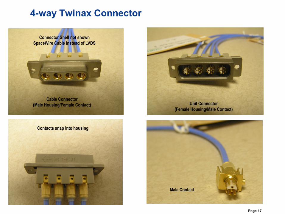
4-way Twinax Connector
Cable Connector
(Male Housing/Female Contact) Unit Connector
(Female Housing/Male Contact)
Contacts snap into housing
Male Contact
Connector Shell not shown
SpaceWire Cable instead of LVDS
Page 18
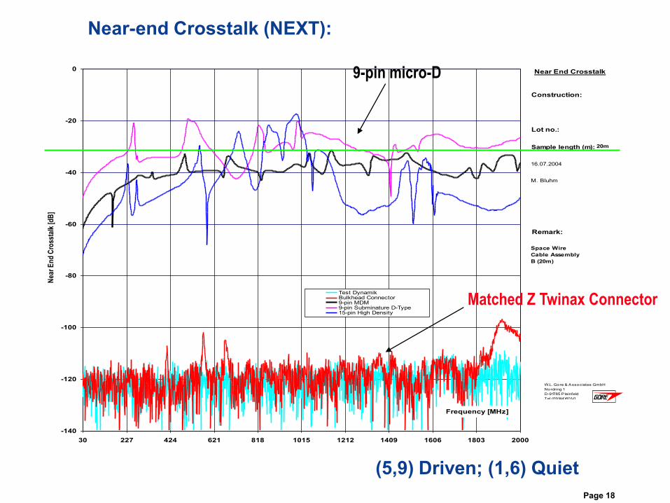
Near-end Crosstalk (NEXT):
-140
-120
-100
-80
-60
-40
-20
0
30 227 424 621 818 1015 1212 1409 1606 1803 2000
Frequency [MHz]
Nea
r E
nd
Cro
ssta
lk [d
B]
Test DynamikBulkhead Connector9-pin MDM 9-pin Subminature D-Type15-pin High Density
16.07.2004
M. Bluhm
W.L. Gore & Associates GmbH
Nordring 1
D-91785 Pleinfeld
Tel.(09144)601-0
Remark:
Space Wire
Cable Assembly
B (20m)
Construction:
Lot no.:
Near End Crosstalk
Sample length (m): 20m
Matched Z Twinax Connector
9-pin micro-D
(5,9) Driven; (1,6) Quiet
Page 19
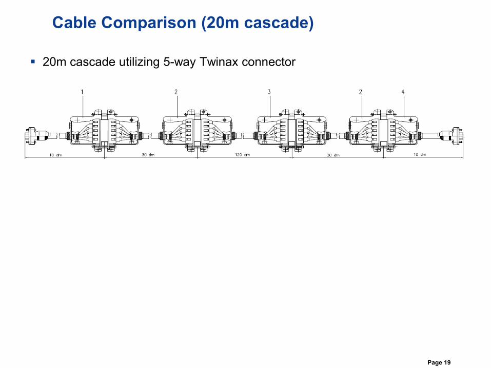
Cable Comparison (20m cascade)
20m cascade utilizing 5-way Twinax connector
Page 20
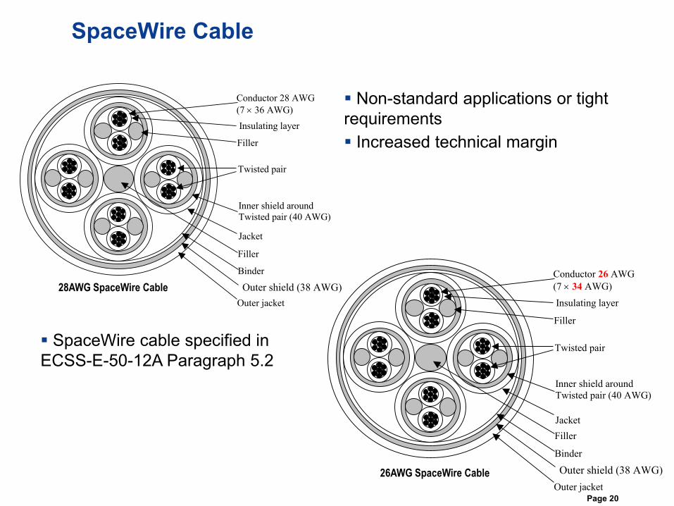
SpaceWire Cable
Conductor 26 AWG
(7 34 AWG)
Insulating layer
Filler
Twisted pair
Inner shield around
Twisted pair (40 AWG)
Jacket
Filler
Binder
Outer shield (38 AWG)
Outer jacket
Conductor 28 AWG
(7 36 AWG)
Insulating layer
Filler
Twisted pair
Inner shield around
Twisted pair (40 AWG)
Jacket
Filler
Binder
Outer shield (38 AWG)
Outer jacket
28AWG SpaceWire Cable
26AWG SpaceWire Cable
Non-standard applications or tight
requirements
Increased technical margin
SpaceWire cable specified in
ECSS-E-50-12A Paragraph 5.2
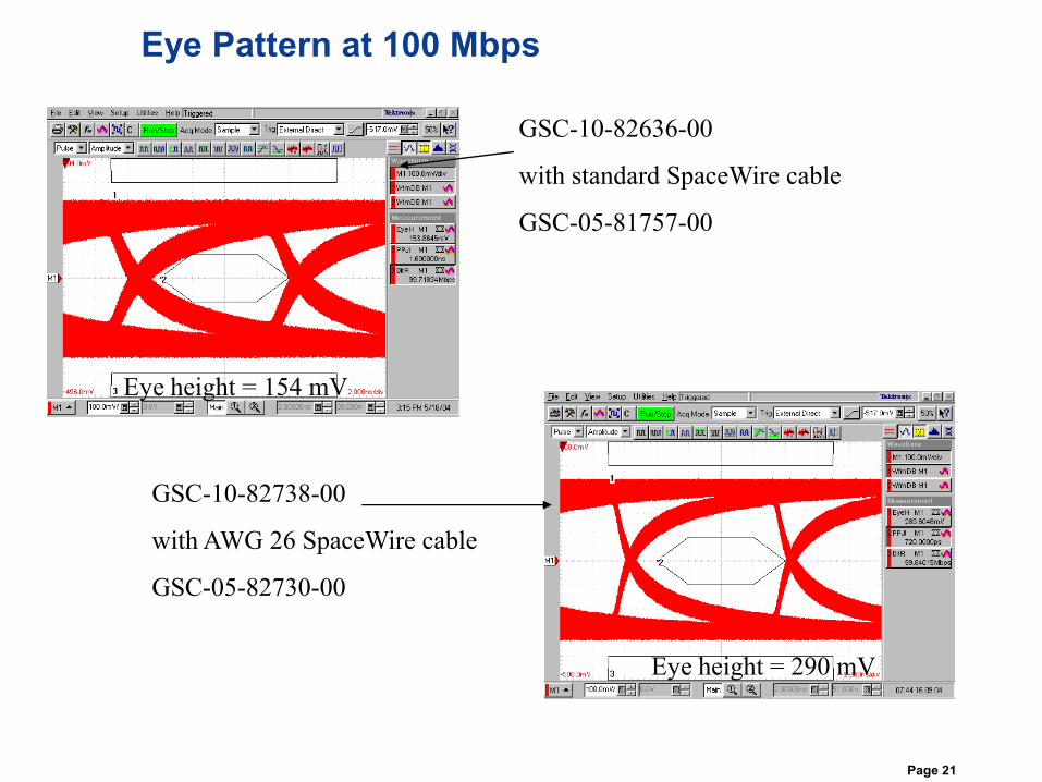
Page 21
GSC-10-82636-00
with standard SpaceWire cable
GSC-05-81757-00
GSC-10-82738-00
with AWG 26 SpaceWire cable
GSC-05-82730-00
Eye height = 290 mV
Eye Pattern at 100 Mbps
Eye height = 154 mV
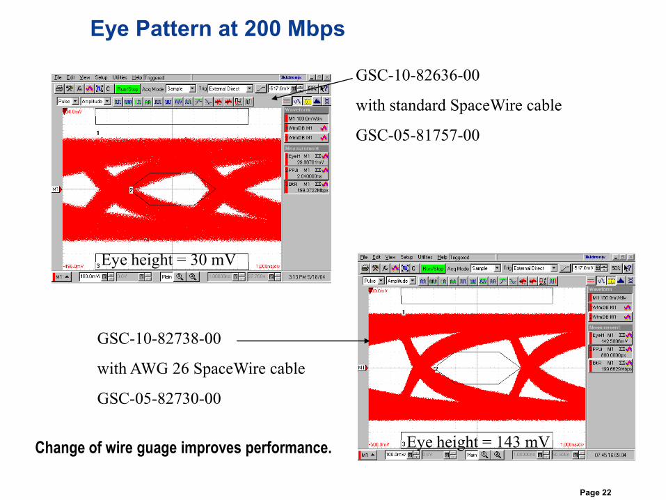
Page 22
GSC-10-82636-00
with standard SpaceWire cable
GSC-05-81757-00
GSC-10-82738-00
with AWG 26 SpaceWire cable
GSC-05-82730-00
Eye Pattern at 200 Mbps
Eye height = 143 mV
Eye height = 30 mV
Change of wire guage improves performance.
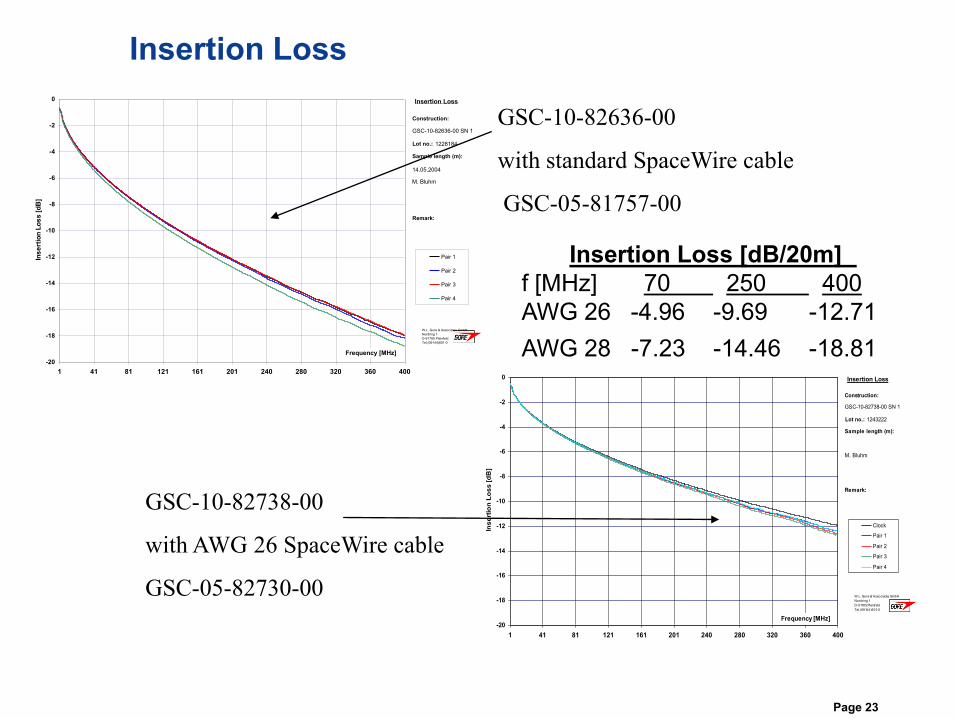
Page 23
GSC-10-82636-00
with standard SpaceWire cable
GSC-05-81757-00
GSC-10-82738-00
with AWG 26 SpaceWire cable
GSC-05-82730-00
-20
-18
-16
-14
-12
-10
-8
-6
-4
-2
0
1 41 81 121 161 201 240 280 320 360 400
Frequency [MHz]
Ins
ert
ion
Lo
ss
[d
B]
Pair 1
Pair 2
Pair 3
Pair 4
GSC-10-82636-00 SN 1
14.05.2004
M. Bluhm
W.L. Gore & Associates GmbH
Nordring 1
D-91785 Pleinfeld
Tel.(09144)601-0
Remark:
Construction:
Lot no.:
Insertion Loss
Sample length (m):
1228184
-20
-18
-16
-14
-12
-10
-8
-6
-4
-2
0
1 41 81 121 161 201 240 280 320 360 400
Frequency [MHz]
Ins
ert
ion
Lo
ss
[d
B]
Clock
Pair 1
Pair 2
Pair 3
Pair 4
GSC-10-82738-00 SN 1
M. Bluhm
W.L. Gore & Associates GmbH
Nordring 1
D-91785 Pleinfeld
Tel.(09144)601-0
Remark:
Construction:
Lot no.:
Insertion Loss
Sample length (m):
1243222
Insertion Loss [dB/20m]
f [MHz] 70 250 400
AWG 26 -4.96 -9.69 -12.71
AWG 28 -7.23 -14.46 -18.81
Insertion Loss
Page 24
Summary
AWG 26 SpaceWire cable has improved technical performance
Twinax connector configurations useful in some applications
Testing indicates good performance of Twinax Connectors
Mass and size should be weighed against technical gains