spaceborne gps current status and future visions
DESCRIPTION
Project Monarch GPS Apollo Success; Future Mission to Mars Success 2005 Drill; for 2014 Public ReleaseTRANSCRIPT

Spaceborne GPSCurrent Status and Future Visions
Frank H. Bauer, Kate Hartman and E. Glenn Lightsey
NASA Goddard Space Flight Center
Greenbelt, Maryland, 20771301-286-8496
frank, bauer@gsfc, nasa. gov
ABSTRACT
The Global Positioning System (GPS), developed by the
Department of Defense, is quickly revolutionizing thearchitecture of future spacecraft and spacecraft systems.
Significant savings in spacecraft life cycle cost, in
power, and in mass can be realized by exploiting Global
Positioning System (GPS) technology in spacebomevehicles. These savings are realized because GPS is a
systems sensor--it combines the ability to sense spacevehicle trajectory, attitude, time, and relative ranging
between vehicles into one package. As a result, a
reduced spacecraft sensor complement can be employed
on spacecraft and significant reductions in space vehicle
operations cost can be realized through enhanced on-
board autonomy. This paper provides an overview of the
current status of spaceborne GPS, a description of
spaceborne GPS receivers available now and in the near
future, a description of the 1997-1999 GPS flight
experiments and the spaceborne GPS team's vision forthe future.
INTRODUCTION
GPS technology holds great promise for terrestrial aswell as space-based users. The world is just beginning to
understand the tremendous benefits and great potential
that this technology can deliver to the military and
civilian transportation industry. Safer air travel,
improvements in search and rescue systems, improved
Earthquake monitoring, tractor-trailer tracking and
enhanced farming techniques are just some of the
terrestrial-based spinoffs from this technology.Handheld GPS receivers are now available for less than
$100 and millions are being sold each year. The benefits
of this technology on Earth is extensive. The benefits
are equally extensive for spacecraft and space systems.
Significant reductions in spacecraft costs, improvements
in spacecraft autonomy and new, exciting scientific
opportunities can be accomplished through the infusionof this technology on spacecraft and spacecraftconstellations of the future.
While this technology holds great promise, its
incorporation on spacecraft has been delayed for several
reasons. See figure 1. The tremendous success of the
very lucrative terrestrial GPS market has, in fact, stifled
the development of spaceborne GPS receivers.
Companies with GPS expertise are more interested in thelucrative terrestrial-based GPS market. They are not
interested in diverting their GPS talent on the relatively
small space-based market. This has restricted the
development of spaceborne receivers to meet thedemands of future spacecraft requirements.
In addition to the above problem, there are many
technical challenges that must be overcome before
space-borne GPS bears all its fruit. GPS receivers thatare used in space are very different than their terrestrial-
based cousins. The high speeds of low Earth orbiting
spacecraft result in signal doppler and doppler rate which
are significantly higher than what is observed on the
ground. Also, the GPS satellites rise and set on low Earth
orbiting vehicles much faster than terrestrial based users
(approximately 45-50 minutes versus 6 hours). Thesedifferences result in a significantly larger search space
for spaceborne GPS requiring a much faster solution.
Figure 1 outlines these problems and describes the
technological "stairsteps" that the spaceborne GPScommunity needs to climb before spacebome GPS has
fully matured.
The spaceborne GPS community must expediently
overcome the GPS technology hurdles shown in figure I
and develop a stable of robust spaceborne GPS receivers
that meet future mission requirements. To this end, the
GPS team at the Goddard Space Flight Center (GSFC)
has been fostering government/university/industry
partnerships in spaceborne GPS technology. The
objectives of these partnerships are to promote the
development and use of spaceborne GPS through a four-
pronged program. The elements of this program include:
I) The development of spaceborne GPS receiverswhich satisfy the future spacecraft mission
requirements.

2) The development of the techniques required to
integrate this technology on spacecraft in a costeffective manner.
3) The validation of this technology through a series offlight experiments; and,
4) The development of enhanced autonomy techniquessuch as autonomous orbit control and formation
flying.
The GPS technology program being accomplished at
NASA Goddard encompasses the use of GPS primarily
as an engineering sensor as compared to using GPS for
science measurements. As an engineering sensor, GPSdetermines spacecraft attitude, relative and absolute orbit
position, and time. When used as a science instrument,
GPS performs gravity, atmospheric sounding, oceanreflection, and ionospheric sounding measurements.
While the science and engineering aspects of using GPS
in space follow somewhat similar hardware developmentpaths, the receiver robustness, data requirements, and
receiver operation in an engineering application is verydifferent from its use as a science instrument. This is
primarily because the engineering function must
maintain space vehicle health and is geared towards
reducing space mission costs through reduced sensor
complements and enhanced vehicle autonomy. To
achieve these objectives, the GPS receiver must provide
real-time, autonomous, onboard support to the
spacecraft. This contrasts with the objectives of GPS
science applications which demand extensive postprocessing of the data to glean as much information from
the science data as possible. This data reduction is
currently performed by a cadre of ground operationspersonnel. Moreover, the GPS science instrument is not
required to maintain mission critical functions; thus, theelectronics hardware embedded in the receiver and the
Roadblocks Impeding
Space-Based GPS Technology
• Percel_on that Gilts technology is mature and requi¢_ no res_wch
am/devdopment effort to fly in SlatCe
• More lucrative GPS receiver mart_ for terrestrial applications
• Differences _n space-lmsed & gromai-lmed GPS reception
• Require numermm flight expeg4.nwnts to _climb the technological
stairsteps"poinltq - Stellar p_inhlqg - _4niq
- AnttadeDele_miuaam -AnimdeCaanml -Malapath_
- AIIIII_mOIS OrlM| l]_f. - P,_lLlllllve R_rill_ - AIIl_l_llOIIII Oriel _111_'_
- Farmllos Ityialg - GEOdtEO Opa - I_'_M,e Tlmmll
- Scmo¢ ralmamms - TYdRX capa_|ty - Uuldtd eald start
Figure 1: Roadblocks to Space-Based GPS
algorithms used to obtain the GPS data can be verydifferent from a GPS engineering device.
VISION FOR SPACEBORNE GPS
The current vision for spaceborne GPS technology is
encapsulated in figure 2.
Space-Based GPS Technology:
Vision of Highly Autonomous Spacecraft
• Vision: Improve space vehicle
autonomy; Reduce design and
operations costs through theinfusion of new GPS hardware and
sensing techniques
• GPS Sensing Capabilities:
• Ataonomous Orbit Determination
4. Accurate Time Synchronization
+ Coarse Attitude Det_ion
+ Accurate Relative Ranging
Between Platforms
• 21st Century Engineering
Applications:
4. Autonomous Onboard Navagatiort.
Operations, and Orbit Control
• Attitude Delerrah'talion and Control
• Rendezvous & Proximity Operations
÷ Formation Flying/Coorditlal_l
Platforms
÷ Micrmatellit_ w/3 _is control
• GPS Perfornrmnce at GEO and Above
• Governrc_t. University. and
Commercial Partnership
Figure 2: Spaeeborne GPS Vision
As shown above, the vision embodies the exploitation of
GPS as a systems sensor----capable of determining
spacecraft trajectories autonomously, delivering precise
time synchronization to spacecraft electronics, sensing
vehicle attitude and measuring the relative distancebetween space vehicles. Achieving the vision outlined in
figure 2 will take many years to complete. The current
generation of receivers, being installed on today's flight
experiments, will definitely open new doors in space
vehicle design and autonomy. However, they will not
fully achieve the revolutionary changes in spacecraft
sensing and autonomy outlined in the vision statement
depicted in figure 2. The GPS technology roadmap,
shown in figure 3, illustrates that this will require
approximately 10 years of concentrated development
effort and probably three generations of flight receiver
designs--the first generation of which is available today.
The current generation (first generation) of engineeringreceivers have been installed on several spacecraft and
are being put through a battery of tests to validate their
on-orbit performance and to understand their limitations.
The information gleaned from these tests will be used to
give GPS users the information they need to successfully
integrate these current generation receivers onto their
spacecraft and will also give the GPS development team
the knowledge required to improve future receiverdesigns.
The second generation of receivers, expected to be
available at the beginning of the next millennium, will
be miniaturized versions of their predecessors, fabricated

1996 2001 2006
• Radiation Hardened
•Algorithms adapted for space
•Navigation (500 m Real Time,60 m Post Process)•Precise Time through Bus (2ms)
Commercial]
L I
•Robust algorithms•Modular S/W•Miniaturized H/W(GPS on Board)• Enhanced initialization
• Navigation (5m WAAS)• Relative Navigation (10m)•Ops above the constellation
•TX/RX Capability•GPS on a Chip•Cold start w/o Ephemeris•Dual Freq. Miniaturized
•Attitude Determination (0.25-0.1 °) .Autonomous Orbit Control
LGlobalstarJ[Spa.anLiteI LCOMSATJ ISMEX/MIDEXl [
Figure 3: GPS Receiver Technology Roadmap
Key
on multi-chip modules. They will include modular
object oriented software and robust algorithms to
significantly improve their operation in space. The
receiver will be capable of quick (5 minute) cold start
initialization without ground intervention. This new
receiver set will enable real-time space vehicle
navigation to meter performance levels using the WideArea Augmentation System (WAAS) and will provide
relative navigation knowledge to 10 meters.
The third generation of spaceborne receivers will enable
inexpensive micro-spacecraft. Electronics technology
improvements will allow the third generation receiver to
be further miniaturized. A transmit/receive capability
will be included in this generation receiver to enable
autonomous formation flying. The "GPS-on-a-Chip"
vision, proposed in 1995 by Goddard, Stanford
University, and JPL, should be fully realized with this
receiver. Robust use of GPS in Geostationary Earth Orbit
(GEO) and High Earth Orbit (HEO) will be realized withthis generation of receivers.
•GEO & HEO Applications•Relative Navigation (5 cm)•Formation Flying•Microsat Constellations
TDRSS ]
GOES ]
GPS-AN ENABLING TECHNOLOGY
Incorporation of GPS on space vehicles enables three
primary technologies: space vehicle autonomy, ground
station automation and virtual spacecraft constellations.
Without GPS, all three of these technologies could grow
and mature over time--but not without a high ground
operations cost penalty and long-term developmentschedules. With GPS, each of these technologies become
spacecraft breakthrough technologies, providing low
cost, attractive opportunities for missions of the future.
Space Vehicle Autonomy--Low cost autonomous
navigation, on-board maneuver planning andautonomous constellation control all become feasible
when GPS is employed. Traditionally, spacecraft
navigation would be accomplished on the ground
through ranging and trajectory determination techniques.
Planning and controlling the orbit of a single spacecraft
from the ground is labor intensive. Performing these
functions from the ground on several spacecraft
simultaneously is extremely complex and introduces an
overwhelming ground personnel requirement. This
would place a considerable burden on the ground

operationsteamwho mustnot only ensurethatallspacecraftmaintainproperorbitalspacing,but alsomonitorspacecraftstatesof healthwhilecollectingallpertinentdata requiredto achieveoverallmissionsuccess.The time, orbit and attitude data, obtained from
GPS, enables spacecraft system developers to
accomplish autonomous orbit maneuver planning and
autonomous stationkeeping maneuvers on-board the
spacecraft. This results in a substantial reduction in
mission operations costs.
Other spacecraft autonomy technologies enabled using
GPS are low cost, standardized spacecraft timing
systems through the spacecraft data bus, vehicle attitudedetermination and attitude control, and autonomous data
transmissions over ground stations. Miniaturized copiesof a GPS receiver can also serve as the heart of an
autonomous micro-sciencecraft providing attitude and
orbit sensing, attitude commanding, orbit control,
command and data handling services, and science
instrument timing all in one package.
Virtual Platforms--- Developing the technology to
produce virtual platforms will be a long range challenge.Similar to its enabler--GPS technology--there are
several technological hurdles that must be overcome to
go from autonomous navigation and constellation control
to one and two way lbrmation flying and finally to
virtual platforms (see figure 4). Despite these hurdles,
the Earth and space science community has already
started defining the new science measurements and
science missions that can be performed using clusters of
spacecraft flying in formation in virtual platforms.
One technological hurdle critical to enable autonomous
formation flying is the (transmit/receive) space vehicle
crosslink system that is to be incorporated in the third
generation GPS receiver (see figure 3). When the third
generation receiver is coupled with autonomous on-
board maneuver planning and orbit control software,
autonomous relative ranging between space vehicles and
formation flying becomes feasible. Using the crosslink-
GPS receiver/transmitter as an enabling step, relative
ranging and formation flying technology is expected to
revolutionize both manned and unmanned space vehicle
operations in the near future.
Once formation flying techniques are perfected, the
space and Earth science communities can perform new
and exciting missions unimaginable just a few years ago.
In the future, autonomous Space Shuttle and Space
Station rendezvous and docking using GPS will becomecommonplace. Very low cost scientific payloads, such
as Spartan, will be deployed from Space Station, fly in
Closed Loop Navigation
Autonomous Constellation
ControlAutonomous Formation Flying
of Multiple Satellites
1996 1999 2001 2006 2010
_IGINS- SEC-
On Board Autonomous 1- Way 2- Way True VirtualManeuver Constellation Formation Formation Formation PlatformPlanning Control F_ng Fbo_ f b_
Real Time Real Time Real Time Chase S/C Chase& Multiple S/C Na_gation &On Board On Board On Board reacts to Tanget SIC Na_gatir_ Attitude
Orbit _ V AV data f_om react in collective/X & reactingDetermination Determination Execution Target S/C concert autonomously collectively
Figure 4: Autonomous Onboard Orbit Determination and Control
formation, and autonomously return for eventual
retrieval. In the process, these enabling technologies
will allow synchronous science measurements to occur
on multiple space vehicles. Multiple spacecraft
formation flying as a virtual platform and gatheringconcurrent science will soon be feasible once the GPS
and tbrmation flying technologies have fully matured.
Ground station automation--The ultimate goal in
ground station automation is to develop true "LightsOut" operations. In other words, operating spacecraft
with a small team that is only present on the first
(daylight) shift. Since the flight and ground segments are
intertwined, spaceborne GPS and GPS on the ground are
required to enable lower cost "Lights Out" systems. As a
result, GPS receivers are being incorporated in ground
stations as a timing synchronization source. Ground
operations personnel and specific ground passes can be
reduced since ranging and Ephemeris uplinks are no
longer required. Ground-based formation flying would
require a substantial ground personnel requirement. This
is not needed if autonomous formation flying is
employed.
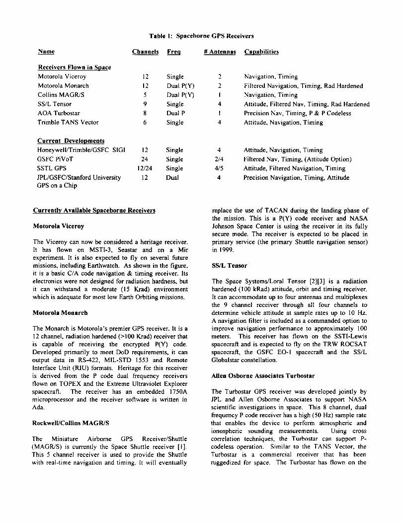
18" DSS DishGPS Attitude
"GPS Attitude Array D,.' Receiver
AIt / Az RotatorRotator Controller
Antenna System Rotatori Interface
DSS Receiver: and Monitor Computer
Client Component Support Equipment
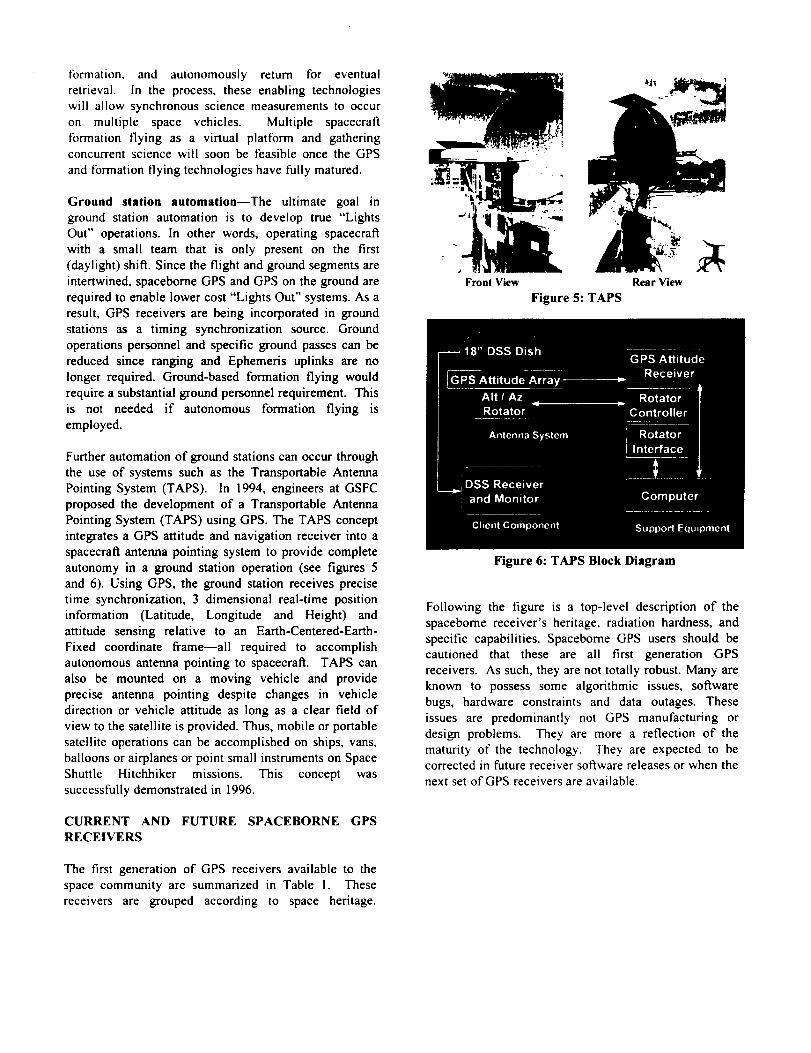
Further automation of ground stations can occur through
the use of systems such as the Transportable Antenna
Pointing System (TAPS). In 1994, engineers at GSFC
proposed the development of a Transportable Antenna
Pointing System (TAPS) using GPS. The TAPS concept
integrates a GPS attitude and navigation receiver into a
spacecraft antenna pointing system to provide complete
autonomy in a ground station operation (see figures 5
and 6). Using GPS, the ground station receives precise
time synchronization, 3 dimensional real-time positioninformation (Latitude, Longitude and Height) and
attitude sensing relative to an Earth-Centered-Earth-
Fixed coordinate frame--all required to accomplish
autonomous antenna pointing to spacecraft. TAPS can
also be mounted on a moving vehicle and provide
precise antenna pointing despite changes in vehicle
direction or vehicle attitude as long as a clear field of
view to the satellite is provided. Thus, mobile or portable
satellite operations can be accomplished on ships, vans,
balloons or airplanes or point small instruments on Space
Shuttle Hitchhiker missions. This concept was
successfully demonstrated in 1996.
CURRENT AND FUTURE SPACEBORNE GPS
RECEIVERS
The first generation of GPS receivers available to the
space community are summarized in Table 1. These
receivers are grouped according to space heritage.
Front View Rear View
Figure 5: TAPS
Figure 6: TAPS Block Diagram
Following the figure is a top-level description of the
spaceborne receiver's heritage, radiation hardness, and
specific capabilities. Spaceborne GPS users should be
cautioned that these are all first generation GPS
receivers. As such, they are not totally robust. Many areknown to possess some algorithmic issues, software
bugs, hardware constraints and data outages. These
issues are predominantly not GPS manufacturing or
design problems. They are more a reflection of the
maturity of the technology. They are expected to becorrected in future receiver software releases or when the
next set of GPS receivers are available.
Name
Receivers Flown in Space
Table I: Spaceborne GPS Receivers
Channels Freq # Antennas Capabilities
Motorola Viceroy 12 Single
Motorola Monarch 12 Dual P(Y)
Collins MAGR/S 5 Dual P(Y)
SS/L Tensor 9 Single
AOA Turbostar 8 Dual P
Trimble TANS Vector 6 Single
Current Developments
Honeywell/Trimble/GSFC SIGI 12 Single
GSFC PiVoT 24 Single
SSTL GPS 12/24 Single
JPL/GSFC/Stanford University 12 Dual
GPS on a Chip
2
2
I
4
!
4
Navigation, Timing
Filtered Navigation, Timing, Rad Hardened
Navigation, Timing
Attitude, Filtered Nav, Timing, Rad Hardened
Precision Nav, Timing, P & P Codeless
Attitude, Navigation, Timing
4
2/4
4/5
4
Attitude, Navigation, Timing
Filtered Nav, Timing, (Attitude Option)
Attitude, Filtered Navigation, Timing
Precision Navigation, Timing, Attitude
Currently Available Spaceborne Receivers
Motorola Viceroy
The Viceroy can now be considered a heritage receiver.It has flown on MSTI-3, Seastar and on a Mir
experiment. It is also expected to fly on several future
missions, including Earthwatch. As shown in the figure,
it is a basic C/A code navigation & timing receiver. Its
electronics were not designed for radiation hardness, but
it can withstand a moderate (15 Krad) environment
which is adequate for most low Earth Orbiting missions.
Motorola Monarch
The Monarch is Motorola's premier GPS receiver. It is a
12 channel, radiation hardened (> 100 Krad) receiver that
is capable of receiving the encrypted P(Y) code.
Developed primarily to meet DoD requirements, it can
output data in RS-422, MIL-STD 1553 and Remote
Interface Unit (RIU) formats. Heritage for this receiver
is derived from the P code dual frequency receivers
flown on TOPEX and the Extreme Ultraviolet Explorer
spacecraft. The receiver has an embedded 1750A
microprocessor and the receiver software is written inAda.
Rockwell/Collins MAGR/S
The Miniature Airborne GPS Receiver/Shuttle
(MAGR/S) is currently the Space Shuttle receiver [1].
This 5 channel receiver is used to provide the Shuttle
with real-time navigation and timing. It will eventually
replace the use of TACAN during the landing phase of
the mission. This is a P(Y) code receiver and NASA
Johnson Space Center is using the receiver in its fully
secure mode. The receiver is expected to be placed in
primary service (the primary Shuttle navigation sensor)in 1999.
SS/L Tensor
The Space Systems/Loral Tensor [2][3] is a radiation
hardened (100 kRad) attitude, orbit and timing receiver.
It can accommodate up to four antennas and multiplexesthe 9 channel receiver through all four channels to
determine vehicle attitude at sample rates up to 10 Hz.
A navigation filter is included as a commanded option to
improve navigation performance to approximately 100meters. This receiver has flown on the SSTI-Lewis
spacecraft and is expected to fly on the TRW ROCSAT
spacecraft, the GSFC EO-I spacecraft and the SS/LGlobalstar constellation.
Allen Osborne Associates Turbostar
The Turbostar GPS receiver was developed jointly by
JPL and Allen Osborne Associates to support NASAscientific investigations in space. This 8 channel, dual
frequency P code receiver has a high (50 Hz) sample rate
that enables the device to perform atmospheric and
ionospheric sounding measurements. Using cross
correlation techniques, the Turbostar can support P-
codeless operation. Similar to the TANS Vector, theTurbostar is a commercial receiver that has been
ruggedized for space. The Turbostar has flown on the
GPS-METandWakeshield2& 3. It isexpectedto flyon theDanishORSTED,theSouthAfricanSUNSATandtheU.S.GeosatFollow-on(GFO)satellites.UsingtheInternationalGPSServicefor Geodynamics(IGS)globalnetworkof GPSreceivers,theTurbostar receiver
can achieve sub-meter post-process orbit determination
performance.
Trimble TANS Vector
The Trimble TANS Vector is a commercial terrestrial
receiver that has been ruggedized for use in space.
Spaceborne software was developed for this receiver
through a partnership with engineers from Trimble,
Stanford University, and GSFC. Using this software, the
receiver provides 3-axis attitude to approximately 0.5
degree [4][5], navigation to 450 meters and timing to 0.1
microsecond. Approximately a dozen receivers haveflown on missions such as Orbcomm, Crista SPAS,
REX-II, GADACS, GANE as well as several Space
Shuttle Experiments. The receiver is somewhat radiation
soft with a tolerance of approximately 8 kRad. Despite
this, the receiver has supported low Earth orbiting
missions for well over a year and in some cases 3 years.
Current Developments for Space
The current spaceborne GPS receivers available
commercially have not kept pace with NASA's current
and future requirements. NASA needs receivers that arelow cost ($100K or less), low power and can be
reconfigured to meet the specific mission requirements.None of the low cost receivers currently available meet
the demanding real-time navigation requirements (<100
meters) of many Earth science missions. All the
spacebome receivers have been derived from terrestrial
receivers, inheriting the zenith-pointing assumptions that
limit the robustness required in spaceborne applications.Therefore, NASA has initiated several in-house GPS
development initiatives to bring spaceborne GPS to
spacecraft users. These, as well as the low-cost GPS
receiver development at Surrey Satellite TechnologyLimited are described below.
GSFC PiVoT
An in-house NASA GSFC development is called PiVoT,which stands for Position, Velocity, Time. This modular
receiver design is based on the GEC Plessey Chipset
[6][7]. PiVoT is expected to be able to withstand a
moderate (15-20 kRad) radiation environment. Robust
algorithms embedded in PiVoT will allow the receiver to
operate in any vehicle orientation and support the
demanding navigation requirements of 95% of NASA's
Earth science and space science missions. The design
will support up to 4 antennas and an attitude sensing
option is planned. The protoflight PiVoT receiver will
be delivered in 5/98 with protoflight qualification
completed around 10/98.
SIG! Honeywell/Trim ble/Collins/GSFC
The Space Integrated GPS/INS
Inertial Navigation System for
NASA's Space Shuttle,
International Space Station andCrew Return Vehicle. The INS
consists of a Ring Laser Gyro,GPS receiver, inertial
navigation computer and power
supply mounted in a standard
Embedded GPS INS housing.
(SIGI) represents a new
Figure 7: SIGi
See figure 7. Two spacebome receivers are being
produced. The first is the Collins GEM dual frequency
receiver. It is both C/A and P(Y') code capable and
supports navigation and timing functions. This receiver
will be embedded in the SIGI that flies on the Space
Shuttle. The second receiver is being developed through
a partnership between Honeywell, Trimble and NASA
Goddard. This receiver will support the International
Space Station and Crew Return Vehicle. The Trimble
receiver used in this application supports attitude,
navigation and timing. The receiver can track up to 12
satellites. It is an upgrade of the successful TANS
Vector receiver. The attitude algorithms and softwareembedded in this receiver are being developed by NASAGSFC.
JPL/GSFC/Stanford GPS on a Chip
The GPS-on-a-Chip development effort is a joint,
collaborative program with JPL, Stanford University and
NASA GSFC as partners. JPL is developing the GPS-
on-a-Chip hardware and Stanford and Goddard will
develop the algorithms, software and validate the system
performance through ground-based testing. The
development approach was to develop the receiver
requirements, design and develop the prototype receiverand make the design available to future industrial
partners. The Phase I prototype receiver is expected to be
completed by the year 2000. The GPS on a Chip project
started in 1996. GPS-on-a-Chip is being designed to be
modular with an open architecture hardware and
software design and developed to be flight qualified in
the future. GPS-on-a-Chip will support multiple
antennas, can be used as a dual frequency P code
receiver or a single frequency C/A code receiver. It is
expected to support attitude, filtered navigation and
timing. Prototypes of this receiver are planned to be

flown on the SAC-C (1999), Champ (1999), and theGRAC E (2001 ) missions.
Surrey Satellite
Surrey Satellite Technology Limited (SSTL) is also
developing a GPS receiver based on the GEC Plessey
chipset [6][7]. Similar to the PiVoT design, the SSTL
receiver will incorporate radiation protection. The
receiver uses an ARM60 32 bit RISC microprocessor.
This receiver will support an on-orbit software uplink, a
feature that is lacking (but should be required) in many
commercial GPS receivers. Data is output via a CAN
interface, which is an automobile standard, similar to
RS-422. The receiver is being incrementally upgraded
and flown as an experiment on several Microsats. The
first flight is expected on TMSAT in late 1997 or Early
1998. TMSAT is a Technology Transfer Micro-satellite
being constructed for Thailand. This flight will include
the receiver in a 2 antenna configuration. The first flightof the 4/5 antenna receiver will be on UoSAT-12 which
is expected to fly in 1998.
1997-1999 FLIGHT EXPERIMENT OVERVIEW
The experiments accomplished prior to 1997 and those
planned for 1997-1999 expect to validate some of the
initial concepts of using GPS for spacecraft engineering
functions and to climb the technological stairsteps
depicted in figure 1. Each experiment is unique,
providing a wealth of information to the spaceborne GPS
receiver design community. These experiments will
provide valuable information on using GPS as an
autonomous navigation instrument, as a spacecraft
attitude determination sensor, as a precise time
synchronization a source, and as a relative rangingsensing device.
To date, two spacecraft GPS experiments have flown in
1997. Table 2 outlines the eight Goddard-collaborated
spaceborne GPS experiments scheduled for 1997-1999.
The table includes the mission name, the spacecraft, the
planned experiment objectives, the type of GPS receiver
(or receivers) to be flown and the launch date. After
reviewing these collaborative experiments, one may
observe that there is some overlap in some of themissions. It should be noted that this was done
intentionally. The GPS team's intent is to obtainexperimental data which is critical to factor into future
GPS receiver designs in a timely fashion despite launch
vehicle, spacecraft, or experiment failures that are part of
the risk of flying in space. The following paragraphs
provide more details on each experiment.
GPS Attitude Determination Flyer (GADFLY)
Experiment on the SSTI-Lewis Spacecraft
The Global Positioning System (GPS) Attitude
Determination Flyer (GADFLY) [8] experiment was
launched on the Small Satellite Technology Initiative
(SSTI) Lewis spacecraft in August 22, 1997 (see figure
8). The primary objective of the GADFLY experiment
was to demonstrate and validate the cost-saving, systems
engineering features that can be exploited by using GPS
receivers in space vehicles. The experiment's physical
hardware included four GPS antennas and pre-amplifiers,
cross-strapped to two Space Systems/Loral GPS Tensor
receivers. This was expected to be the first long-term,
on-orbit flight of a fully space-qualified GPS receiver
capable of simultaneously sensing space vehicle attitude,
orbit and providing a precise time reference.
The Space Systems/Loral Tensor receivers were flown
on GADFLY primarily as an attitude determination
experiment. However, an integral part of this experiment
was to demonstrate precise time distribution and provide
autonomous real-time navigation solutions to the
spacecraft subsystems and other experiments. The
spacecraft clock used a timing signal and a "time at the
tone" message from the GPS Tensor to maintain a timing
accuracy to better than two milliseconds. A GPS timing
testbed, developed at the Goddard Space Flight Center,was used to test the techniques required to transfer the
GPS timing information from the GPS Tensor onto aMIL-STD-1553 spacecraft bus. In addition to the timing
information, navigation solutions provided by the GPS
Tensor was intended to support the Lewis science
objectives. To improve the real-time navigation accuracy
delivered by the GPS Standard Positioning Service, the
GPS Enhanced Orbit Determination Experiment
(GEODE) [9] was being developed for GADFLY.GEODE, an enhanced navigation filter developed at the
Figure 8: GADFLY on SSTI-Lewis

Goddard Space Flight Center, is expected to provide
navigation accuracy on the order of l0 meters 16. The
GADFLY performance goals are shown in table 2.
The GADFLY team includes members from NASA
Goddard Space Flight Center, TRW (the SSTI-Lewis
spacecraft manufacturer), Space Systems/Loral, NASA
Johnson Space Center, Stanford University, Computer
Sciences Corporation, and Orbital.
Table 2: GADFLY Performance Goals
Attitude Determinatio®
Orbit Determination
[Spacecraft Reqniremenl
None (using GPS)
150 m 30 in-track
150 m 3a cross-track
230 m 30. radial
Time Tags: 2 reset.
I Hz update
GADFLY Goals
0.45 ° 30"
450 m 30" unfiltered
50 m 30" Tensor filtered
60 m 30" GEODE
Time Tags: < 1 mse¢
I Hz update
Precise Timing I msec, I Hz update Time Tags < I msec
Reference Discrete Pulse < I lasec
Table 3:1997-1999 Space-Based Experiments
Experiment Carrier Goals Receiver Date
GADFLY SSTI-Lewis Filtered OD, SS/L Tensor 11/5/97Time, RT AD
Seastar GPS Seastar
Earthwatch GPS Earthwatch/Earlybird
RT OD, Timing
RT AD, Timing,RT Precise OD
SHUCS STS-91/SPACEHAB RT AD, RT OD, Ant.
Pointing, Time
Motorola Viceroy Xx/xx
Trimble TANS Vector 12/14/97
Motorola Viceroy
Trimble TANS Vector 5/98
Clark-GPS SSTI-Clark RT AD, Filtered OD Trimble TANS Vector 6/98
AMSAT GPS AMSAT Phase IIID RT AD, Ops above Trimble TANS Vector 7/98GPS Constellation
SAC-A GPS SAC-A RT AD, RT OD, Trimble TANS Vector 7/98
Spinning AD
Enhanced Formation EO-I RT OD (20 m), Time, SSFL Tensor 5/99Flying AOC, AFF
GPS on the Shuttle All Shuttles RT OD Collins MAGR/S Numerous
KEY: RT=Real Time, OD=Orbit Determination, AD=Attitude Determination, AOC=Autonomous Orbit Control,AFF=Autonomous Formation Flying Techniques
SSTI-Lewis Mission Results
Prior to the mission, the GADFLY experiment was
subjected to a battery of tests to validate that the Tensor
receiver was ready for flight. These were successfully
completed and the GADFLY team was confident that the
experiment would provide and outstanding data return.During the first ground station pass, the Tensor receiver
was activated, acquired and locked on to sufficient
satellites to produce a navigation and time solutionwithin 20 minutes. The receiver remained active until
August 26 when the spacecraft was observed to be
spinning at a 2 rpm rate. This unrelated attitude control
problem resulted in the total loss of the Lewis mission
and a total loss in the GADFLY experiment. Despite
this unfortunate setback, the GPS community benefited
significantly from the GADFLY experiment. Some of
the experiment highlights include: 1) the flight
qualification of the Tensor--the first radiation hardened
receiver capable of determining attitude, orbit and time;2) the on-orbit demonstration of the Tensor reciever for a
brief period (several days) in a navigation and timing
configuration; 3) the development of the GEODEsoftware which is expected to serve over 95% of all

Earthorbitingspacecraft;4) the developmentoftechniques to distribute time through a 1553 bus; and
5) the development of low cost GPS attitude self survey
techniques using an antenna fixture. The lessons learned
from the Lewis mission are being applied to future flight
experiments, including future flights of the Tensorreceiver on the TRW ROCSAT and the GSFC EO-I
spacecraft.
Seastar
The Seastar spacecraft, developed by Orbital, includesthe Goddard SeawiFS instrument. It was launched on
August 1, 1997 and is currently in a 705 km sun-synchronous orbit. A 12 channel, 2 antenna Motorola
Viceroy receiver was flown on this mission to support
mission orbit determination and vehicle timing. The use
of GPS on this mission was not actually a flightexperiment but a mission-critical capability. Prior to the
flight, Motorola and Orbital recognized the need to fullyunderstand and characterize how the receiver would
perform in space. They requested the use of the GSFC
GPS facility[10] to independently validate the Viceroyreceiver performance. The GSFC GPS facility employs a
40 channel Nortel GPS simulator. The Viceroy was put
through a battery of tests, which proved to be critical in
improving the receiver's performance. As a result of this
testing, software modifications were made prior to flight
which have permitted the Seastar spacecraft to provide
outstanding Earth science measurements. Thus, preflighttesting of GPS in a simulator environment is crucial
when the receiver is to be used as a critical navigationdevice.
EarthWatch-Earlybird
The Earlybird-I satellite is being built by Orbital/CTA
for EarthWatch, Inc. This spacecraft represents
EarthWatch's first entry into the commercial Earth
imaging satellite business. This mission will be placed
in a 470 km, sun synchronous orbit. Of particular
interest to the GPS community is that this spacecraft will
flying two different GPS receivers--the Motorola
Viceroy and the Trimble TANS Vector C/A code
receivers. The TANS Vector, using four antennas, willprovide attitude, orbit and time data to the vehicle and
the Viceroy will provide orbit and time information to
the spacecraft. This mission has a very aggressive 3-5 m
(l-sigma) orbit accuracy requirement. A team consistingof members from Orbital, University of Colorado, and
Van Martin Systems [I I] have developed a low cost,
high accuracy Orbit Determination System for this
mission. This system employs a MicroCosm precision
orbit software system, derived from NASA Goddard'sGEODYN II, and the use of the International GPS
Service tbr Geodynamics (IGS) [12] ground system.Using this system, Davis, et. al. achieved 3-7 m orbit
accuracies using single frequency carrier phase data from
a Trimble receiver in the 800 km RADCAL [13] orbit.
The GPS team also hopes to get high accuracy attitude
data from this mission since the spacecraft includes highaccuracy attitude sensors on-board that can be used to
calibrate the GPS attitude data. The Earlybird-I
spacecraft is tentatively scheduled for launch on
December 14, 1997. The GPS collaborative experimentson this mission are sponsored by EarthWatch,
Orbital/CTA, GSFC, Trimble, Motorola, University ofColorado, Van Martin Systems and Microcosm.
Clark-GPS
In addition to the GADFLY experiment on the SSTI-
Lewis spacecraft, a GPS experiment will also be
included on the SSTI-Clark spacecraft [14], which is
currently slated to be launched in June, 1998 (see figure
9). The objectives of the Clark-GPS experiment is to
study real-time GPS orbit and attitude determination.
The experiment's physical hardware includes four GPS
antennas and pre-amplifiers, cross-strapped to twoTrimble TANS Vector GPS receivers.
Figure 9: SSTI-Clark
There are six cases of interest that will be studied with
the Clark-GPS orbit determination experiment. The GPS
Operational case will study the use of an onboard
estimator and periodic updates to improve the orbit
accuracy from the base GPS Standard Positioning
Service (SPS) accuracy of 150 meters, lo, to better than
25 meters, lo. The GPS Dropouts case will look at the
GPS data dropouts that occur in various portions of the
spacecraft orbit, particularly at high altitudes wherevisibility of GPS satellites is at its worst. Degradation of
the orbit estimator propagated orbit position during these
dropouts will also be characterized. The third case that
will be studied is the ability of the orbit estimator to
reject GPS Outliers through the use ofa chi-square test.

The rburth case to be studied for the Clark-GPS orbit
determination experiment is the performance of the GPS
receiver and the orbit propagator during and after orbit-
adjust maneuvers. The case of an inoperative GPSreceiver is also considered, with the ability on the
spacecraft to switch to the redundant GPS receiver and
reinitialize the orbit estimator by ground command.
Finally, the case of autonomous initialization of the orbitestimator after safehold will also be studied.
The Clark-GPS attitude determination experiment will
study the generation of GPS attitude for a spacecraft in
earth-pointing mode. As a long-term attitude
determination experiment, the static and dynamic error
sources of GPS attitude can be characterized by
comparing them to more accurate attitude information
from SSTI-Clark's star tracker and other spacecraft
sensors. The impact of vehicle multipath on GPS attitude
determination accuracy can also be investigated.
The Clark-GPS experiment on SSTI-Clark has been put
together by a team consisting of CTA, Welch
Engineering, and NASA Goddard Space Flight Center.
AMSAT-GPS
AMSAT Phase 3D is the latest in a long series ofsatellites built by the Radio Amateur Satellite
Corporation (AMSAT). It is typical of AMSAT satellites
in that it is being built almost entirely by a world-wide
volunteer staff of amateur radio operators and satellite
enthusiasts from AMSAT, the NASA Goddard Space
Flight Center, and others throughout the world. The
Phase 3D satellite is scheduled for launch as a secondary
payload on an Ariane 5 flight in 1998.
The AMSAT-GPS experiment will be the first to study
the use of GPS signals above the GPS constellation.AMSAT Phase 3D will be in a 4,000 x 47,000 kilometer
Molniya orbit, its apogee well over the 20,000 kilometer
altitude of the GPS satellites. In addition to providingfurther long-term, real-time GPS attitude and orbit
determination experience, the AMSAT-GPS experiment
will be able to map the GPS constellation signal patterns
available above the constellation, as well as give an
understanding of the robustness and limitations of
making use of GPS in this region.
The hardware for the AMSAT-GPS experiment willconsist of two Trimble TANS Vector GPS receivers,
along with two sets of four GPS antennas. Four patch
antennas will be located on the perigee side of the
spacecraft, while four high-gain antennas will be placed
on the apogee side.
SPACEHAB Universal Communications System(SHUCS)
The SPACEHAB Universal Communications System
(SHUCS) uses a flat panel L-band phased array antenna
mounted to a two-axis pointing system to communicate
through an lnmarsat satellite. SHUCS is mounted on topof SPACEHAB. SPACEHAB is a reusable commercial
habitation module that is flown in the Orbiter cargo bay.
This system, similar to the TAPS system described
previously, allows customers to receive 64 kbps of data
directly and send data commands in real-time; bypassingthe NASA communications network. The antenna
pointing system is controlled by a Trimble TANS Vector
navigation and attitude receiver provided by NASA
Goddard. The SHUCS experiment is planned to fly on
STS-91 in May 1998. This represents the first time aspaceborne pointing system will use GPS to steer an
antenna to a target. During the flight, GPS receiver and
SHUCS operational data will be provided to theSPACEHAB and Goddard experimenters in real-time
through the lnmarsat/SHUCS link-up. An educational
outreach program has been built into this experiment to
allow the Goddard obtained flight data to be available to
students in real time through a World Wide Web site.
SAC-A
The SAC-A
spacecraft is a small
free-flying satellite
designed by CONAEin Argentina. SAC-A
will be deployed from
a hitchhiker bridge
mounted in the SpaceShuttle Endeavour in
July 1998. The SAC-
A GPS experiment is
expected to performthe first ever attitude
and navigation
sensing on a spinning
spacecraft. As shown
Figure 10: SAC-A
in figure 10, four patch antennas with a very short
baseline (<0.5 meter) are mounted on the top of the
SAC-A spacecraft. A Trimble TANS Vector receiverwill be employed on SAC-A to determine the vehicle
attitude, orbit and time. This is a collaborative
partnership between CONAE in Argentina and theNASA Goddard Space Flight Center.

EO-I Enhanced Formation Flying Experiment
The primary objective of the enhanced formation flying
experiment on the New Millenium Program (NMP) EarthOrbiter-I (EO-I) mission is to demonstrate onboard
autonomous relative navigation and formation flying
control between the EO-1 and Landsat-7 spacecraft. An
automated mission design and automated maneuver
planning tool, AUTOCON, which was developed by AI
Solutions under direction by the Goddard GN&C team,
has been used for operational mission design.
AUTOCON is being modified to operate onboard thespacecrafl to support autonomous constellation control
and formation flying. This will be accomplished by
having the flight control system plan a maneuver that
places EO-1 within 1 minute of separation from Landsat-
7 and then maintain that separation to a tight tolerance of6 seconds for an extended period of time.
The algorithms and software tools for this demonstration
will be developed using a modular approach so that they
can easily be used onboard future Earth orbiting
missions. These algorithms [15] will be implemented
using fuzzy logic engines for constraint checking andcontrol of the formation flying algorithms.
The key benefits of this enhanced formation flying
technology are to eliminate routine ground maneuverplanning and commanding requirements, reduce costs,
enhanced science capabilities, and to advance the
technology for complete lights-out application for the
New Millennium Program. The system will provide a
real-time low-cost formation flying control with the
flexibility to meet a broad range of mission requirementsincluding ground track, inclination, and altitude control
as individual or multiple spacecraft requirements.
Space Shuttle Flights
Since 1993, engineers at the NASA Johnson Space
Center have sponsored several different experiments tovalidate the concepts required to fly GPS as an in-line
avionics component on the US Space Shuttles. The
current phase of Shuttle/GPS operations is the use of a
Precise Positioning Service (PPS) receiver as a single
string navigation device. A Rockwell Collins MAGR/S
[1][16] receiver was chosen for this phase of the
development effort. During the flights, the navigation
data is downlinked to the ground and is available in real-
time on the astronaut crew displays. During landing, the
GPS system performance will be compared to the results
obtained by TACAN, the primary Shuttle navigation
device. The single string GPS system is currently
incorporated on 3 Shuttles (Discovery, Atlantis and
Endeavour). It was first demonstrated on the STS-79
mission which was launched on September 16, 1996.
The final phase of the Shuttle GPS validation is to
incorporate a three string GPS on all four Orbiters. Since
the Shuttle avionics systems requirement is to be twofault tolerant, a minimum of three GPS receivers are
required per Space Shuttle. Once this final phase hasbeen completed and the system validated, TACANservice will be removed for future Shuttle Missions and
the GPS antennas will be installed in place of the
TACAN antennas. Currently, TACAN navigation isprovided for the Shuttle within 300 miles of the landing
site. The first flight of the GPS-only navigation solution
will be on STS-92, which is tentatively scheduled for
January 1999.
Using GPS for Space Shuttle Navigation will allow the
Shuttle to eliminate its need for TACAN navigation. In
addition, GPS is expected to improve on-orbit navigation
performance and save approximately $3-4 Million per
year by eliminating the need for Microwave Landing
System ground stations.
CONCLUSIONS
Significant systems cost, power, and weight savings, as
well as enhanced vehicle autonomy are expected from
exploiting GPS technologies in future space vehicles.
Several spacebome GPS receivers have been developedand several others are being developed to ensure that
future spacecraft and constellations of spacecraft canoperate with minimal ground intervention. A combined
industry, university and government team of partners
have defined the vision and direction for spacebome
GPS and are implementing this vision in the most costeffective manner.
REFERENCES
[1] Murray, S.V., "Global Positioning System for the
Space Shuttle", Presented at NASA GSFC, February,1996.
[2] Fuller, R.A., Kemper, B., and Rodden, J.J.,
"Spacecraft Guidance and Control with GPS TENSOR",
19 'h Annual AAS Guidance and Control Conference,
Breckenridge, CO, February 7-11, 1996.
[3] Sacchetti, A., "GPS for Orbit and Attitude
Determination: Hardware Design and Qualification Plan
for a Spaceborne Receiver," ION-GPS-94, Salt Lake
City, UT, September 20-23, 1994.

[4] Freesland,D., et. al., "GPS Based Attitude
Determination, The REX-II Experience", AIAA/USU
Small Satellite Conference, Logan, UT, September 1996.
[5] Lightsey, E.G., et al., "Flight Results of GPS Based
Attitude Control on the REX-II Spacecraft ", ION-GPS-
96, Kansas City, MO.
[6] Theroux, Y., "Open Architecture Design for GPSApplications," ION-GPS-95, Palm Springs, CA,
September 12-15, 1995.
[7] Clark, T., Varney, D. and Bauer, F., "A Low Cost
Spacecraft Receiver for Orbit and Attitude
Determination," ION-GPS-94, Salt Lake City, UT,
September 20-23, 1994.
[8] Bauer, F. H., et. al., "The GPS Attitude
Determination Flyer (GADFLY): A Space-Qualified
GPS Attitude Receiver on the SSTI-Lewis Spacecraft",
ION-GPS-95, Palm Springs, CA.
[9] Hart, R.C., et. ai. "Global Positioning System (GPS)
Enhanced Orbit Determination Experiment (GEODE) on
the Small Satellite Technology Initiative (SSTI) Lewis
Spacecraft", ION-GPS-96, Kansas City, MO.
[10] O'Donnell, J. R., Jr., et. al., "Testing of GPS-Based
Attitude Control Systems", ION-GPS-96, Kansas City,MO.
[11] Davis, G.W., et. al., "A Low Cost, High Accuracy
Automated GPS-Based Orbit Determination System for
Low Earth Satellites", ION-GPS-97, Kansas City, MO.
[12] Beutler, G., and Neilan, R., International GPS
Service for Geodynamics Resource Information, January1996.
[13] Lightsey, E.G., et al., "Application of GPS attitude
Determination to a Gravity Gradient Stabilized
Spacecraft," ION-GPS-93, Salt Lake City, UT,
September 1993.
[14] Freesland, D., et. aL, "SSTI-Clark Attitude
Determination and Control Subsystem Status Review",
CTA Design Review, January 1996.
[15] Bauer, F.H., Bristow, J., Folta, D., Hartman, K.,
How, J. and Quinn, D., "Satellite Formation Flying using
an Innovative Autonomous control System (Autocon)
Environment", AIAA GN&C Conference, New Orleans,
LA, August 1997.
[16] Kirpes, R.R., and Burkle, M.W., "Ballistic
Propagation of the MAGR-Shuttle Navigation Solution",
ION Proceedings of the 52 ndAnnual Mtg, Cambridge,MA, June 1996.